Operation Manual Proportional Valve VP60 Series
22
Operation Manual Proportional Valve VP60 Series Before starting work read these instructions. This manual contains proprietary information. No part of this publication may be reproduced, transcribed or transmitted in any form without the written consent of the publisher. Every effort has been made to ensure that the information contained in this manual is accurate. All rights reserved.
Transcript of Operation Manual Proportional Valve VP60 Series

Operation ManualProportional Valve VP60 Series
Before starting work read these instructions.This manual contains proprietary information. No part of this publication may be reproduced, transcribed or transmitted in any form without the written consent of the publisher. Every effort has been made to ensure that the information contained in this manual is accurate. All rights reserved.
TCF Fellbach (2021).02 03/21
VP60 Analogue / IO-Link
Our policy is one of continued research and development. We therefore reserve the right to amend, without notice, the specifications given in this document.
Content
1. General 32. Liability 43. Functional Safety 54. Basic Function 65. Pneumatic Connection 86. Electrical Connection 97. Assembly Instructions 118. Troubleshooting and Diagnosis 129. Transport and Storage 1510. Disposal 1511. Appendix 16
This document, as well as the data, specifications and other information presented in it are the sole property of Norgren. It may notbe reproduced or given to third parties without their consent.
Our policy is one of continued research and development. We therefore reserve the right to amend, without notice, the specifications given in this document.
Order number 7503481000000050Revision: 2
Manufacturer's Address:Norgren GmbHStuttgarter Str. 120D-70736 Fellbach

TCF Fellbach (2021).0303/21
VP60 Analogue / IO-Link
Our policy is one of continued research and development. We therefore reserve the right to amend, without notice, the specifications given in this document.
1. General
1.2. Explanation of Symbols Safety Notice
1.3. Specifications
Other Symbols
The following symbols are used to emphasise instructions, outcomes, lists, references and other elements in these instructions.
DANGER
This symbol and the word ‚danger‘ indicates an immediately dangerous situation that may result in death or serious injury if not avoided.
The factory-set capacity ranges for the valve are also indicated on the nameplate of the respective device.
Warning!
This symbol and the word ‘warning’ indicates a potentially dangerous situation that may result in death or serious injury if not avoided.
CAUTION!
This combination of symbol and signal word indicates apossibly hazardous situation that may result in damage to property or environmental damage if it is not avoided.
Indicates tips and other useful information.
Other symbols Meaning
1., 2., 3., Step-by-step instructions
• Lists with no specific order
These instructions will enable you to safely install, set up and operate the proportional valve VP60 in the analogue or IO-Link version. These instructions are an integral part of the product and must be accessible topersonnel. Personnel must carefully read through and understand these instructions before starting work of any kind on the valves. Following all of the safety and handling instructions contained in this manual is a fundamental requirement for safe working.
1.1 Information about these Instructions

TCF Fellbach (2021).04 03/21
VP60 Analogue / IO-Link
Our policy is one of continued research and development. We therefore reserve the right to amend, without notice, the specifications given in this document.
2. Liability
Physical modifications to the VP60 proportional valve may only be carried out by the manufacturer. If the valve requires repairs or maintenance beyond the activities described in these instructions, this work may only be carried out by the manufacturer of the proportional valve or by persons expressly authorised and trained by the manufacturer. Failure to comply with the above provisions will invalidate the warranty claims. The manufacturer accepts no liability for any damage incurred.
Caution!This product is for use in industrial compressed air systems only. It is to be used where the pressure and temperature ratings listed in the data sheet are not exceeded. Contact Norgren directly before using the product in non-industrial applications, in life support or other systems not covered in the published instructions. Misuse, wear or malfunction can cause components used in pneumatic systems to fail in a variety of ways. System designers are strongly advised to consider the failure modes of all component parts used in pneumatic systems and to take adequate safety precautions to prevent injury to personnel and damage to equipment in the event of such a failure.
System designers are required to provide safety information to the end user in the operation of the system.
2.1. Liability
2.3. General Safety Instructions/ Proper Usage
TCF Fellbach (2021).0503/21
VP60 Analogue / IO-Link
Our policy is one of continued research and development. We therefore reserve the right to amend, without notice, the specifications given in this document.
3. Functional Safety
The VP60 is not a design with design-related fail-safe properties.Therefore, no safety-related properties can be guaranteed at valve level.For machine controls (complex mechatronic systems) with the VP60, a risk analysis in accordance with e.g. EN-ISO12100 is urgently recommended.Information on the current standard situation can be obtained from the VDMA or the BGIA.
DANGER - Danger due to hazardous movementChanges to the valve configuration can lead to unwanted movements or changes to connected consumers under air supply. Please ensure a safe operating condition before changing the valve configuration. This also applies in particular to changes via the USB configuration interface or the IO-Link parameters.Use suitable stop and vent valves in the supply lines and at the consumer connections for enabling.
Warning! - Danger from compressed airConnections 2 & 4 can still be under pressure for a long time even after the pressure supply to connection 1 has been switched off!Protect yourself and others by not removing any pressurised connections and wear suitable personal protective equipment when working!Depressurise the system before carrying out any workAll work must be carried out by qualified pneumatics specialists
Warning! - clogging of silencersBlockage of the silencers can lead to malfunction of the valveEnsure appropriate air quality
Warning! - Risk of injury due to noiseOnly operate the valve with suitable silencersAlways wear ear protection when working
Warning! - Risk of injury due to insufficient qualificationAs the operator, ensure that work is only carried out by qualified personnelTrain the operating personnel comprehensively in safety issuesHave electrical installations carried out only by qualified electricians
Note:
3.1. General Safety Instructions

TCF Fellbach (2021).06 03/21
VP60 Analogue / IO-Link
Our policy is one of continued research and development. We therefore reserve the right to amend, without notice, the specifications given in this document.
4. Basic function
The VP60 is a 5/3-way proportional valve of nominal size 8.
The flow-optimised, metal-seated 5/3-way spool is adjusted as quickly as possible to the position corresponding to the setpoint by means of a moving coil and position sensor via a µP control loop.In the production process, a setpoint / setpoint travel map is determined for each VP60 in such a way that a linear relationship between setpoint and flow results under constant pressure conditions. Device-specific manufacturing tolerances are compensated for by this procedure. The result is an idealised V-characteristic in the ratio of input setpoint to pneumatic flow. However, the sensitively adjustable, proportional zero-cut characteristic is maintained in any case. When de-energised or in the event of faults (see valve operating states), a spring presses the spool into the preferred position. The low-loss, digital electronics are integrated in the valve. There are no user-serviceable parts in the valve assembly.
The VP60 represents a bi-directional, linearized variable throttle and enables, for example, the stepless, reversible speed control of double-acting cylinders or reversible pneumatic motors.
The VP60 represents a bi-directional, linearized variable throttle. Proportional to the input signal, the flow can be varied continuously between negative and positive maximum values. In the middle position, all ports are blocked. Setpoints above the middle open the passages 1 to 2 and 4 to 5. Setpoints below the middle open the paths 1 to 4 and 2 to 3. The latter are de-energized or, in the event of a fault, spring-loaded fully open. In the delivery state, the valve is set to mode (5/3-way).
4.1. General Description
4.2. Application
4.3. Function and Functional Types

TCF Fellbach (2021).0703/21
VP60 Analogue / IO-Link
Our policy is one of continued research and development. We therefore reserve the right to amend, without notice, the specifications given in this document.
Filtered compressed air (see technical features) is available at port 1. The actuator (2.e. cylinder) is connected to ports 2 and 4. Ports 3 and 5 are used for venting. Silencers with low flow resistance should be connected here.The reaction of the actuator (e.g.: retraction or extension of a cylinder) in the event of a fault (e.g. power failure) results from the connection diagram of the same to VP60 ports 2 and 4.If no movement is desired in the event of a fault (see operating states of the valve), the responsible system designer should provide additional shut-off valves between the valve and actuator.
For consumers with constant air flow, which require only one supply connection and no venting (e.g.: nozzles or turbines). The following sub-functions result:2/2 NC (normally closed): The air is connected to port 2. ports 3, 4 and 5 are closed.Via VP-Tool*, the entire setpoint range can be assigned to the 2/2 valve function with the effect of (opening/closing). If this is not done, the VP60 remains closed below the center. An exhausting effect can be adjusted above the middle. Middle = too, max. Set point = max. Flow2/2 NO (normally open): The air is connected to connection 4. connections 2,3 and 5 are closed.Via VP-Tool*, the entire setpoint range can be assigned to the 2/2 valve function with any effect (opening/closing). If this is not done, the VP60 remains closed above the middle. An exhaust effect can be set below the middle. min. Input=max. Flow, Middle=to.
4.3.1. Function Type (5/3-way)
4.3.2. Function Type (2/2-way)
Note:The accuracy of the valve remains unchanged by the use of the 2/2-way mode, which is only used for adaptation to the conditions and the purpose of use in your plant.
*) In the IO-Link version, the function type must be set via the parameters described in the IODD. Details can also be found in the parameter description list in the appendix.

TCF Fellbach (2021).08 03/21
VP60 Analogue / IO-Link
Our policy is one of continued research and development. We therefore reserve the right to amend, without notice, the specifications given in this document.
5. Pneumatic Connection
Port size 1: System pressure Port size 2: Operation ConnectionPort size 3: Venting working connection 2Port size 4: Operation ConnectionPort size 5: Venting working connection 4
These units are designed for use with clean, dry, oil-free compressed air.Compressed air shall be provided in accordance with ISO8573-1; grouping 2-3-1. A filtering of the supply air (<3 microns) is strongly recommended. For flow-intensive applications, screw fittings with a straight outlet should be preferred in order to avoid possible pressure losses.
5.1 Block Diagram of the Valve Function (5/3 way)
5.2 Operating Medium
Caution! When using compressed air containing oil and water, the dynamics and the service life of the valve can be significantly reduced.
Caution!Under no circumstances should Teflon sealing tape be used to seal the connections as this tends to break down into small particles. These can contaminate the valve mechanics and cause malfunctions.
The pneumatic connections for input and output pressure have a G1/4" or ¼" NPT internal thread, a suitable screw fitting must be used.

TCF Fellbach (2021).0903/21
VP60 Analogue / IO-Link
Our policy is one of continued research and development. We therefore reserve the right to amend, without notice, the specifications given in this document.
6. Electrical Connection
Nominally, the VP60 is supplied with 24 V DC between Vs and GND. The electronics are protected against incorrect polarity of the supply and will not be damaged. The power supply must be isolated from the mains.
(PELV according to EN 60204-1, DIN VDE 0100-410, IEC 364-4-41,HD 384.4.41 S2, EN 60079-14).
6.1 Pin Assignment
6.1.1 Variant Analogue
6.1.2 Variant IO-Link
6.2 Power Supply
Note:The device must be connected by a qualified person. The national and international regulations for the installation of electrical devices must be observed. The valve body must always be integrated into the equipotential bonding of the plant (grounding).
Pin Colour (Typ.) Ref. Port size
1 white Iin Setpoint input current 4..20 mA (load resistance 500R)
2 brown fault Error output (max.15mA to GND Vs)
3 green -Ud Setpoint input voltage difference negative (0..10V /-5-5V)
4 yellow +Ud Setpoint input voltage difference positive (0..10V /-5-5V)
5 grey I out Current output actual value 4..20mA (Vs GND potential)
6 pink Ub Supply voltage Vs +24V DC
7 blue GND Supply mass (Vs GND)
8 red U out Voltage output actual value 0..10V (Vs GND potential)
Pin Colour (Typ.) Ref. Port size
4 yellow +Ud Setpoint input voltage difference positive (0..10V /-5-5V)
5 grey I out Current output actual value 4..20mA (Vs GND potential)
6 pink Ub Supply voltage Vs +24V DC
7 blue GND Versorgungsmasse (Vs GND)
8 red U out Voltage output actual value 0..10V (Vs GND potential)
Potentials VA & VB are galvanically isolated.

TCF Fellbach (2021).010 03/21
VP60 Analogue / IO-Link
Our policy is one of continued research and development. We therefore reserve the right to amend, without notice, the specifications given in this document.
Note:The actuator system (= position controller of the valve spool) is activated from a supply voltage of 21 V. Although the average current consumption (at 24 V over 10 seconds is limited to 0.6 A and is reversibly reduced to 0.2 A if exceeded, peaks of up to 1.5 A can occur. This must be taken into account when designing the analogue supply.In the IO-Link version, the supply voltage of the valve actuator is ensured via a second channel. The valve is therefore connected via port class B. This must be taken into account when selecting a suitable master.
Note:Power supply units often have an electronic current limiter, the activation of which results in a reduction of the output voltage. As a result, the switch-off threshold of the actuator of the VP60 of 18 V can be undershot. Due to the then drastically reduced current requirement of the valve (~0.08 A), the power supply unit voltage rises again above the switch-on threshold. Possibly an undesired oscillation process is created in this way!
Attention!Supply voltages > 32 V DC can permanently damage the internal overvoltage protection. Since the VP60 enables the actuator from approx. 21 V, a voltage range of 21 to 32 V is specified. However, once the switch-on threshold has been exceeded, operation is guaranteed until the switch-off threshold of approx. 18 V is undershot.This hysteresis (~3V) prevents the above mentioned oscillations if the power supply is designed correctly. Any ripples present (nominally 10% Ub = max. 2.4 V) must be smaller than this hysteresis in order for the VP60 to operate properly.
TCF Fellbach (2021).01103/21
VP60 Analogue / IO-Link
Our policy is one of continued research and development. We therefore reserve the right to amend, without notice, the specifications given in this document.
7. Assembly Instructions
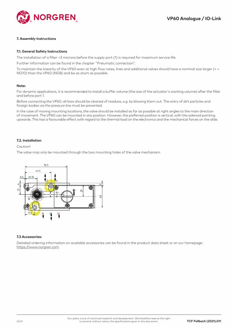
Caution!The valve may only be mounted through the two mounting holes of the valve mechanism.
Detailed ordering information on available accessories can be found in the product data sheet or on our homepage: https://www.norgren.com
The installation of a filter <3 microns before the supply port (1) is required for maximum service life.Further information can be found in the chapter "Pneumatic connection".To maintain the linearity of the VP60 even at high flow rates, lines and additional valves should have a nominal size larger (> = NG10) than the VP60 (NG8) and be as short as possible.
7.1. General Safety Instructions
7.2. Installation
7.3 Accessories:
Note:For dynamic applications, it is recommended to install a buffer volume (the size of the actuator's working volume) after the filter and before port 1.Before connecting the VP60, all lines should be cleaned of residues, e.g. by blowing them out. The entry of dirt particles and foreign bodies via the pressure line must be prevented.In the case of moving mounting locations, the valve should be installed as far as possible at right angles to the main direction of movement. The VP60 can be mounted in any position. However, the preferred position is vertical, with the solenoid pointing upwards. This has a favourable effect with regard to the thermal load on the electronics and the mechanical forces on the slide.

TCF Fellbach (2021).012 03/21
VP60 Analogue / IO-Link
Our policy is one of continued research and development. We therefore reserve the right to amend, without notice, the specifications given in this document.
8. Diagnostics and Troubleshooting
8.1. LED Function
8.1.1. Analogue Version:
8.1.2. IO-Link Version:
LED STATUS red: Valve system fault -> check overvoltage at / if necessary. green: The position control of the valve piston is active.
IOL Flashed green. IO-Link Communications established Lights up permanently green IO-Link interrupted.SF Lights up red: System error. Please run diagnostics or have unit serviced.VB green Logic supply OK red: Logic supply voltage not correctVA green Supply logic OK red: Supply voltage actuator missing / wrong

TCF Fellbach (2021).01303/21
VP60 Analogue / IO-Link
Our policy is one of continued research and development. We therefore reserve the right to amend, without notice, the specifications given in this document.
8.2. Status Byte
8.3 Diagnostic Interface
You can access the status via VPTool or via the IO-Link parameter Index 70 Sub Index 0, as well as in the IO-Link process data. Values in the status byte are signaled via the "STATUS" or the "SF" LED, depending on the variant.
For parameterization and diagnostics, a USB-C interface is located under the dust protection cap centrally on the cover of the valve. The protection cap can be unscrewed counterclockwise using a suitable screwdriver.
Status byte Detailed device status Error description Recommended measure
0b00000001* VAdeviates strongly from nominal voltage. Voltage supply VA deviates too much. Check that a voltage > 18V is applied to VA.
0b00000010 Overcurrent in actuator The current monitoring of the actuator unit has detected a too high current consumption.
The valve may be sluggish or dirty. Service required.
0b00000100 Position deviation too high. The controlled position deviates strongly from the setpoint position. The short occurrence of the error bit during setpoint jumps is not a malfunction.
Dirt or malfunction of the valve mechanics. Supply current may be limited. Service if necessary.
0b00100000 VSdeviates strongly from nominal voltage. The permissible supply voltage is outside the nominal range.
Please check the supply voltage in the supply circuit (if necessary, current limiting active?).
Bit 1 only with Varianle IO-LinkBit 3,4,6,7 reserved for special applications
This interface is connected to a Windows PC via VPTool.
Note: Please note that the EMC conformity and the IP protection lose their validity when the cover is open and the interface is connected. This is only restored when the cover is closed.

TCF Fellbach (2021).014 03/21
VP60 Analogue / IO-Link
Our policy is one of continued research and development. We therefore reserve the right to amend, without notice, the specifications given in this document.
8.4. Status Byte
Error/fault Possible cause Troubleshooting measure
-Output flow too low or not proportional - Connection cross section too small -Check and enlarge if necessary
-no control / maximum flow only - Supply voltage missing/too low - Check voltage and ensure if necessary , check for current limitation
- no output flow
- no setpoint is present
-no supply pressure
-pneumatic connections clogged
- pneumatic connection
- measure the input signals
- check
- check
- check according to the book
- Fluctuations in the output flow - Fluctuations in supply pressure - Diagnosis of the pressure supply
- No reaction of the output flow when the setpoint value is changed - Valve mechanics dirty / damaged - Check filtering and send in device for maintenance
- Output flow is reached only sluggishly- Use of compressed air that has not been cleaned or lubricated
- Dirt in the valve causes friction
- use unlubricated compressed air and install oil filter or suitable FRL unit
-Check filter
- Abrupt change of the flow- Disturbances in the input signal or in the supply
- Insufficient shielding of the setpoint signal or the ground connection
- Installation Improve / Shield
- Improve ground wiring
- Flow rate at setpoint in middle position too high / not as expected
- Faulty mass connection when using the diffential voltage input.
- Internal leakage due to contamination
- Correct the wiring of the system
- Have valve serviced

TCF Fellbach (2021).01503/21
VP60 Analogue / IO-Link
Our policy is one of continued research and development. We therefore reserve the right to amend, without notice, the specifications given in this document.
9. Transport and Storage
10. Disposal
The individual packages are packed according to the expected transport conditions.
Dismantle the valves after decommissioningRecycle the recyclable materials.
Note:The valve and its components can be damaged by transport, corrosion or penetrating foreign bodies.- Transport the valve in the delivery packaging- Do not throw or drop packages- Do not remove the valve from its packaging until immediately before assembly.
Note:Incorrect disposal can be hazardous to the environmentIf in doubt, contact your local authorities for information on environmentally safe disposal.
The valves are packed for immediate installation after delivery. Note in case of prolonged storage:- Leave the valve in the packaging- Store valve dry and dust-free- Do not expose the valve to aggressive media (e.g. salty air).- Protect from sunlight
9.1. Transport
9.2. Storage

TCF Fellbach (2021).016 03/21
VP60 Analogue / IO-Link
Our policy is one of continued research and development. We therefore reserve the right to amend, without notice, the specifications given in this document.
11. Annex
11.1 Component View
11.2. Dimensions
Connector
Protective cover USB connection
Housing
Actuator magnet unit
Valve mechanics

TCF Fellbach (2021).01703/21
VP60 Analogue / IO-Link
Our policy is one of continued research and development. We therefore reserve the right to amend, without notice, the specifications given in this document.
Nameplate exemplary:
The nameplate contains the following information:- Manufacturer- Connection schemes- Model Identification number with version- Pressure range Inlet pressure p1- Setpoint W / Actual value X- Flow- Supply voltage Ub- Limit current I max- Date code, five digits, year/week/day - Digit 1-2 Year of manufacture (2001=A1, 2010=B0, 2021=C1) - Position 3-4 Production week (KW) - Digit 5 Production day (Sunday=1, Monday=2)
11.3 Markings

1 2
50004600
40003600
3000
2000
2600
1600
1000
200600
V
1 4
V
0 1 2 3 4 5 6 7 9 108
- 5 - 4- 4- - 3- 3- - 2- 2- - 1- 1- 0 1 2 4 53
mA4 5,6 7,2 8,8 10,4 12 13,6 15,2 18,4 2016,8
P1
IO-Link0 1023 2047
100
90
80
70
60
40
50
3020
TCF Fellbach (2021).018 03/21
VP60 Analogue / IO-Link
Our policy is one of continued research and development. We therefore reserve the right to amend, without notice, the specifications given in this document.
Flow rate as a function of the set point and P1; P2, P4 = 0 bar (fei outflow):
Flow direction
Input
11.4.Characteristics
0.......................................................................1024..................................................................2047 IO-Link
TCF Fellbach (2021).01903/21
VP60 Analogue / IO-Link
Our policy is one of continued research and development. We therefore reserve the right to amend, without notice, the specifications given in this document.
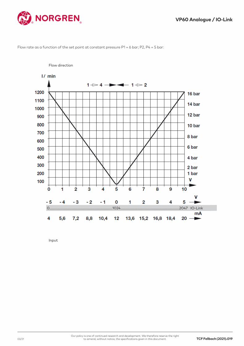
Flow rate as a function of the set point at constant pressure P1 = 6 bar; P2, P4 = 5 bar:
Flow direction
Input
0.......................................................................1024..................................................................2047 IO-Link

TCF Fellbach (2021).020 03/21
VP60 Analogue / IO-Link
Our policy is one of continued research and development. We therefore reserve the right to amend, without notice, the specifications given in this document.
Please for Technical Data see Data Sheet
Frequency response and phase of the slider position controller at 10, 50 and 100% setpoint:
Flow rate as a function of pressure ratio P2/P1 at set points 10, 20, to 100%:
11.5. Technical Data
Valve in Function 5/3. 0% corresponds to the middle position.Fl
ow (%
)
TCF Fellbach (2021).02103/21
VP60 Analogue / IO-Link
Our policy is one of continued research and development. We therefore reserve the right to amend, without notice, the specifications given in this document.
This device is available with an IO-Link communication interface. An IO-Link-capable module (IO-Link master) is required for operation. The IO-Link interface enables direct access to the process and diagnostic data and provides the option of parameterizing the device during operation. In addition, communication is possible via a point-to-point connection with a USB-C adapter cable. Access to the USB interface is gained after removing the cap on the connection lid.
Further parameter descriptions can be found in the IODD of the product at: https://www.norgren.com/de/de/technical-service/software
Device-specific Information The IODDs required for configuring the IO-Link unit and detailed information about the process data structure, diagnostic information and parameter addresses can be found at:https://www.norgren.com/de/de/technical-service/software
11.6 IO-Link General Information
11.7. IO-Link Process Data
11.8. Important IO-Link Parameters
Name Bitlength Structure Value Range
Process Data In 24 (3byte) x = non significant X = significant
Actual value 16 xxxx xxxx XXXX XXXX XXXX XXXX 0..2047 (1024 = Middle position)
Status byte* 8 XXXX XXXX xxxx xxxx xxxx xxxx 0..255
Process Data Out 16 (2byte)
Input 16 XXXX XXXX XXXX XXXX 0..2048
*Status byte description see chapter 8.4.
Param Block & Param Variable Function/Description IndexSub Index
Model Function
V_Function Valve Mode 64 0 UIntegerT_16 Defines the valve mode 5/3-way, 2/2-way
V_BitLogic Status bit Logic 65 0 BooleanT Inverts the logic of the status bit.
V_ZeroOffset Zero-Offset 66 0 IntegerT_16 Defines an offset to the zero point of the valve.
V_Hours Operating Hours 67 0 UIntegerT_16 Operating hours of the valve (ro)
V_Strokes Piston Strokes 68 0 UIntegerT_16 Schiko motion counter
V_ActorCurrent Current/~/ 69 0 UIntegerT_16 Current consumption of the actuator (mA)
V_Errorbytes Error Bytes 70 0 UIntegerT_16 Status/Errorbyte Mirror (s. Prozessdaten PDIn)
For further information, scan this QR code or visit
www.norgren.com
Norgren operates four global centres of technical excellence and a sales and service network in 50 countries, as well as manufacturing capability in Brazil, China, Czech Republic, Germany, India, Mexico UK and the USA.
For information on all Norgren companies visit
www.norgren.com
Supported by distributors worldwide.
Norgren, Buschjost, FAS, Herion, Kloehn, Maxseal and Thompson Valves are registered trademarks of Norgren companies.
Due to our policy of continuous development, Norgren reserve the right to change specifications without prior notice.
OM_IO-Link_VP60 en/03/21Incorporating