Operation Manual - APC · Pre-Start Checklists ... Final Inspection Checklist ... see the UPS...
60
Operation Manual 150/175 KVA Power Distribution Unit PDPM150G6F PDPM150L6F PDPM175G6H 990-4599D Publication Date: November, 2015
Transcript of Operation Manual - APC · Pre-Start Checklists ... Final Inspection Checklist ... see the UPS...
Operation Manual
150/175 KVA Power Distribution Unit
PDPM150G6FPDPM150L6FPDPM175G6H
990-4599D
Publication Date: November, 2015

Schneider Electric Legal DisclaimerThe information presented in this manual is not warranted by Schneider Electric to be authoritative, error free,
or complete. This publication is not meant to be a substitute for a detailed operational and site specific
development plan. Therefore, Schneider Electric assumes no liability for damages, violations of codes,
improper installation, system failures, or any other problems that could arise based on the use of this
Publication.
The information contained in this Publication is provided as is and has been prepared solely for the purpose of
evaluating data center design and construction. This Publication has been compiled in good faith by Schneider
Electric. However, no representation is made or warranty given, either express or implied, as to the
completeness or accuracy of the information this Publication contains.
IN NO EVENT SHALL SCHNEIDER ELECTRIC, OR ANY PARENT, AFFILIATE OR SUBSIDIARY COMPANY
OF SCHNEIDER ELECTRIC OR THEIR RESPECTIVE OFFICERS, DIRECTORS, OR EMPLOYEES BE
LIABLE FOR ANY DIRECT, INDIRECT, CONSEQUENTIAL, PUNITIVE, SPECIAL, OR INCIDENTAL
DAMAGES (INCLUDING, WITHOUT LIMITATION, DAMAGES FOR LOSS OF BUSINESS, CONTRACT,
REVENUE, DATA, INFORMATION, OR BUSINESS INTERRUPTION) RESULTING FROM, ARISING OUT,
OR IN CONNECTION WITH THE USE OF, OR INABILITY TO USE THIS PUBLICATION OR THE CONTENT,
EVEN IF SCHNEIDER ELECTRIC HAS BEEN EXPRESSLY ADVISED OF THE POSSIBILITY OF SUCH
DAMAGES. SCHNEIDER ELECTRIC RESERVES THE RIGHT TO MAKE CHANGES OR UPDATES WITH
RESPECT TO OR IN THE CONTENT OF THE PUBLICATION OR THE FORMAT THEREOF AT ANY TIME
WITHOUT NOTICE.
Copyright, intellectual, and all other proprietary rights in the content (including but not limited to software, audio,
video, text, and photographs) rests with Schneider Electric or its licensors. All rights in the content not expressly
granted herein are reserved. No rights of any kind are licensed or assigned or shall otherwise pass to persons
accessing this information.
This Publication shall not be for resale in whole or in part.
Table of Contents
Overview ............................................................................................ 1Safety ................................................................................................. 1
SAVE THESE INSTRUCTIONS! . . . . . . . . . . . . . . . . . . . . . . . . . . . . . . . . . . . . . . . . . . . . . . . . 1Regulatory agency approval . . . . . . . . . . . . . . . . . . . . . . . . . . . . . . . . . . . . . . . . . . . . . . . . . . 1
Commissioning ................................................................................. 2Pre-Start Checklists . . . . . . . . . . . . . . . . . . . . . . . . . . . . . . . . . . . . . . . . . . . . . . .2
Initial Inspection Checklist . . . . . . . . . . . . . . . . . . . . . . . . . . . . . . . . . . . . . . . . . . . . . . . . . . . 2Electrical Inspection Checklist . . . . . . . . . . . . . . . . . . . . . . . . . . . . . . . . . . . . . . . . . . . . . . . . 2User Interface Inspection Checklist . . . . . . . . . . . . . . . . . . . . . . . . . . . . . . . . . . . . . . . . . . . 2Final Inspection Checklist . . . . . . . . . . . . . . . . . . . . . . . . . . . . . . . . . . . . . . . . . . . . . . . . . . . 2
Start-up Inspection Checklist . . . . . . . . . . . . . . . . . . . . . . . . . . . . . . . . . . . . . . .3
Operation ........................................................................................... 4Display Interface . . . . . . . . . . . . . . . . . . . . . . . . . . . . . . . . . . . . . . . . . . . . . . . . .4
Navigate the display interface . . . . . . . . . . . . . . . . . . . . . . . . . . . . . . . . . . . . . . . . . . . . . . . . 5Top dynamic display . . . . . . . . . . . . . . . . . . . . . . . . . . . . . . . . . . . . . . . . . . . . . . . . . . . . . . . . 5Main menu screen . . . . . . . . . . . . . . . . . . . . . . . . . . . . . . . . . . . . . . . . . . . . . . . . . . . . . . . . . . 5Menu tree . . . . . . . . . . . . . . . . . . . . . . . . . . . . . . . . . . . . . . . . . . . . . . . . . . . . . . . . . . . . . . . . . 6Password protection . . . . . . . . . . . . . . . . . . . . . . . . . . . . . . . . . . . . . . . . . . . . . . . . . . . . . . . 6
Modules Submenu . . . . . . . . . . . . . . . . . . . . . . . . . . . . . . . . . . . . . . . . . . . . . . . .7View Module status . . . . . . . . . . . . . . . . . . . . . . . . . . . . . . . . . . . . . . . . . . . . . . . . . . . . . . . . . 7View Power Distribution Module information . . . . . . . . . . . . . . . . . . . . . . . . . . . . . . . . . . . . 8View circuit status information . . . . . . . . . . . . . . . . . . . . . . . . . . . . . . . . . . . . . . . . . . . . . . . . 9View or reset module energy usage . . . . . . . . . . . . . . . . . . . . . . . . . . . . . . . . . . . . . . . . . . . 10Configure individual load name, location, and alarm thresholds . . . . . . . . . . . . . . . . . . . 11Enable/Disable alarm thresholds for individual loads . . . . . . . . . . . . . . . . . . . . . . . . . . . . 12Enable/Disable module breaker-position alarms . . . . . . . . . . . . . . . . . . . . . . . . . . . . . . . . 12Reset module alarm settings to default . . . . . . . . . . . . . . . . . . . . . . . . . . . . . . . . . . . . . . . . 13Mass configuration of alarms . . . . . . . . . . . . . . . . . . . . . . . . . . . . . . . . . . . . . . . . . . . . . . . . 14Reset module cable settings to their default values . . . . . . . . . . . . . . . . . . . . . . . . . . . . . 15
Subfeeds Submenu . . . . . . . . . . . . . . . . . . . . . . . . . . . . . . . . . . . . . . . . . . . . . .16View general subfeed information . . . . . . . . . . . . . . . . . . . . . . . . . . . . . . . . . . . . . . . . . . . . 16View subfeed operational status and configure name/location . . . . . . . . . . . . . . . . . . . . 17Configure warning and critical alarm thresholds for subfeeds . . . . . . . . . . . . . . . . . . . . . 18Enable or disable alarm thresholds and alarms for subfeed breakers . . . . . . . . . . . . . . . 19Reset subfeed energy usage . . . . . . . . . . . . . . . . . . . . . . . . . . . . . . . . . . . . . . . . . . . . . . . . 20
Totals Submenu . . . . . . . . . . . . . . . . . . . . . . . . . . . . . . . . . . . . . . . . . . . . . . . . .20View total load status . . . . . . . . . . . . . . . . . . . . . . . . . . . . . . . . . . . . . . . . . . . . . . . . . . . . . . 20Total output current by phase . . . . . . . . . . . . . . . . . . . . . . . . . . . . . . . . . . . . . . . . . . . . . . . 21View or reset total energy usage by phase . . . . . . . . . . . . . . . . . . . . . . . . . . . . . . . . . . . . . 22View voltage and frequency . . . . . . . . . . . . . . . . . . . . . . . . . . . . . . . . . . . . . . . . . . . . . . . . . 23View distribution panel settings . . . . . . . . . . . . . . . . . . . . . . . . . . . . . . . . . . . . . . . . . . . . . . 23Configure critical and warning alarm thresholds for total output current . . . . . . . . . . . . 24Configure critical and warning alarm thresholds for total output voltage . . . . . . . . . . . . 25Configure the nominal frequency range to affect alarm conditions . . . . . . . . . . . . . . . . . 26
Environment Submenu . . . . . . . . . . . . . . . . . . . . . . . . . . . . . . . . . . . . . . . . . . .27View the status or configure input contact settings . . . . . . . . . . . . . . . . . . . . . . . . . . . . . . 27Configure output relay settings . . . . . . . . . . . . . . . . . . . . . . . . . . . . . . . . . . . . . . . . . . . . . . 28Configure the alarm relay map . . . . . . . . . . . . . . . . . . . . . . . . . . . . . . . . . . . . . . . . . . . . . . . 29View and configure the subfeed menu . . . . . . . . . . . . . . . . . . . . . . . . . . . . . . . . . . . . . . . . 30
150/175 KVA Modular PDU Operation i
Alarms Submenu . . . . . . . . . . . . . . . . . . . . . . . . . . . . . . . . . . . . . . . . . . . . . . . .31View alarms . . . . . . . . . . . . . . . . . . . . . . . . . . . . . . . . . . . . . . . . . . . . . . . . . . . . . . . . . . . . . . 31
Log Submenu . . . . . . . . . . . . . . . . . . . . . . . . . . . . . . . . . . . . . . . . . . . . . . . . . . .32Admin Submenu . . . . . . . . . . . . . . . . . . . . . . . . . . . . . . . . . . . . . . . . . . . . . . . .33
Configure the network address settings . . . . . . . . . . . . . . . . . . . . . . . . . . . . . . . . . . . . . . 33Upgrade metering board firmware . . . . . . . . . . . . . . . . . . . . . . . . . . . . . . . . . . . . . . . . . . . 34Change the password . . . . . . . . . . . . . . . . . . . . . . . . . . . . . . . . . . . . . . . . . . . . . . . . . . . . . 34Change display interface settings . . . . . . . . . . . . . . . . . . . . . . . . . . . . . . . . . . . . . . . . . . . 35Change the date and time on the display interface . . . . . . . . . . . . . . . . . . . . . . . . . . . . . 36Configure device ID settings . . . . . . . . . . . . . . . . . . . . . . . . . . . . . . . . . . . . . . . . . . . . . . . 36View system component information . . . . . . . . . . . . . . . . . . . . . . . . . . . . . . . . . . . . . . . . . 37Set the configuration to factory defaults . . . . . . . . . . . . . . . . . . . . . . . . . . . . . . . . . . . . . . 37
Help Submenu . . . . . . . . . . . . . . . . . . . . . . . . . . . . . . . . . . . . . . . . . . . . . . . . . .38Use the Help feature . . . . . . . . . . . . . . . . . . . . . . . . . . . . . . . . . . . . . . . . . . . . . . . . . . . . . . . 38
Modbus Configuration.................................................................... 39Configure Modbus through the Display Interface. . . . . . . . . . . . . . . . . . . . . .39
Modbus configuration . . . . . . . . . . . . . . . . . . . . . . . . . . . . . . . . . . . . . . . . . . . . . . . . . . . . . 39
Modbus cable connection. . . . . . . . . . . . . . . . . . . . . . . . . . . . . . . . . . . . . . . . .40
Network Management Configuration ............................................ 41Overview . . . . . . . . . . . . . . . . . . . . . . . . . . . . . . . . . . . . . . . . . . . . . . . . . . . . . . .41
Initial setup . . . . . . . . . . . . . . . . . . . . . . . . . . . . . . . . . . . . . . . . . . . . . . . . . . . . . . . . . . . . . . 41Device IP Configuration Wizard . . . . . . . . . . . . . . . . . . . . . . . . . . . . . . . . . . . . . . . . . . . . . . 41Supported Web browsers . . . . . . . . . . . . . . . . . . . . . . . . . . . . . . . . . . . . . . . . . . . . . . . . . . 42Network management features . . . . . . . . . . . . . . . . . . . . . . . . . . . . . . . . . . . . . . . . . . . . . . 42
Log On . . . . . . . . . . . . . . . . . . . . . . . . . . . . . . . . . . . . . . . . . . . . . . . . . . . . . . . .43URL address formats . . . . . . . . . . . . . . . . . . . . . . . . . . . . . . . . . . . . . . . . . . . . . . . . . . . . . . 43
Security. . . . . . . . . . . . . . . . . . . . . . . . . . . . . . . . . . . . . . . . . . . . . . . . . . . . . . . .43Access priority for logging on . . . . . . . . . . . . . . . . . . . . . . . . . . . . . . . . . . . . . . . . . . . . . . . 43User accounts . . . . . . . . . . . . . . . . . . . . . . . . . . . . . . . . . . . . . . . . . . . . . . . . . . . . . . . . . . . . 43
Watchdog Features . . . . . . . . . . . . . . . . . . . . . . . . . . . . . . . . . . . . . . . . . . . . . .44Network interface watchdog mechanism . . . . . . . . . . . . . . . . . . . . . . . . . . . . . . . . . . . . . . 44Resetting the network timer . . . . . . . . . . . . . . . . . . . . . . . . . . . . . . . . . . . . . . . . . . . . . . . . . 44
Recover from a Lost Password . . . . . . . . . . . . . . . . . . . . . . . . . . . . . . . . . . . .44
Maintenance .................................................................................... 45Parts Replacement. . . . . . . . . . . . . . . . . . . . . . . . . . . . . . . . . . . . . . . . . . . . . . .45
Determine if you need a replacement part . . . . . . . . . . . . . . . . . . . . . . . . . . . . . . . . . . . . . 45Return parts . . . . . . . . . . . . . . . . . . . . . . . . . . . . . . . . . . . . . . . . . . . . . . . . . . . . . . . . . . . . . 45
Power Distribution Modules . . . . . . . . . . . . . . . . . . . . . . . . . . . . . . . . . . . . . . .46Component identification . . . . . . . . . . . . . . . . . . . . . . . . . . . . . . . . . . . . . . . . . . . . . . . . . . . 46Module circuit breaker operation . . . . . . . . . . . . . . . . . . . . . . . . . . . . . . . . . . . . . . . . . . . . 47Installation . . . . . . . . . . . . . . . . . . . . . . . . . . . . . . . . . . . . . . . . . . . . . . . . . . . . . . . . . . . . . . . 48Remove a PDM . . . . . . . . . . . . . . . . . . . . . . . . . . . . . . . . . . . . . . . . . . . . . . . . . . . . . . . . . . . 52
Troubleshooting.............................................................................. 53LEDs on Power Distribution Modules . . . . . . . . . . . . . . . . . . . . . . . . . . . . . . .53Status and Alarm Messages . . . . . . . . . . . . . . . . . . . . . . . . . . . . . . . . . . . . . . .53
150/175 KVA Modular PDU Operationii
OverviewRead the instructions carefully to become familiar with the device before trying to install, operate, service, or maintain it.
About This Manual. This manual contains important safety warnings and instructions, gives an introduction to the display interface and provides detailed information for proper use of the equipment.
Related Documents. Download technical publications or look for updates to your manual at www.schneider-electric.com.
User Comments. Contact www.schneider-electric.com. We welcome your comments about this document.
SafetySAVE THESE INSTRUCTIONS!
This manual contains important instructions that must be followed during installation, operation, and maintenance of the PDU. For safety reasons, only trained users are allowed to operate the display interface and replace the Power Distribution Modules (PDMs).
Regulatory agency approvalThis equipment has been tested and found to comply with the limits for a class A digital device, pursuant to part 15 of the FCC Rules. These limits are designed to provide reasonable protection against harmful interference when the equipment is operated in a commercial environment. This equipment generates, uses, and can radiate radio frequency energy and, if not installed and used in accordance with the installation guide, may cause harmful interference to radio communications. Operation of this equipment in a residential area is likely to cause harmful interference, in which case the user will be required to correct the interference at his own expense.
DANGERHAZARD OF ELECTRIC SHOCK, EXPLOSION, OR ARC FLASH
• Electrical equipment must be installed, operated, serviced, and maintained only by qualified personnel.
• To remove a Power Distribution Module:
- Turn off all power supplying the equipment and perform appropriate lockout/tagout procedures before installing or removing the Power Distribution Module.OR
- If a Symmetra PX is providing power to the Modular PDU, place the UPS into battery operation (to reduce fault current) before removing the Power Distribution Modules. To place the UPS into battery operation, see the UPS Operation Manual.
• The PDU must be installed in accordance with the National Electrical Code or the Canadian Electrical Code and all applicable local codes.
• Service access areas are locked with a Red Key. The Red Keys must remain under the control of qualified service personnel.
• Wear appropriate personal protection equipment (PPE) when performing maintenance on this PDU.
Failure to follow these instructions will result in death or serious injury.
WARNINGUNEXPECTED BEHAVIOR OF APPLICATION
Only trained users should operate the display and replace the Power Distribution Modules.
Failure to follow these instructions can result in death, serious injury, or equipment damage.
CAUTIONUNPROTECTED OUTPUTS
Apply circuit protection to all outputs.
Failure to follow these instructions can result in injury or equipment damage.
1150/175 KVA Modular PDU Operation
Commissioning
Pre-Start Checklists
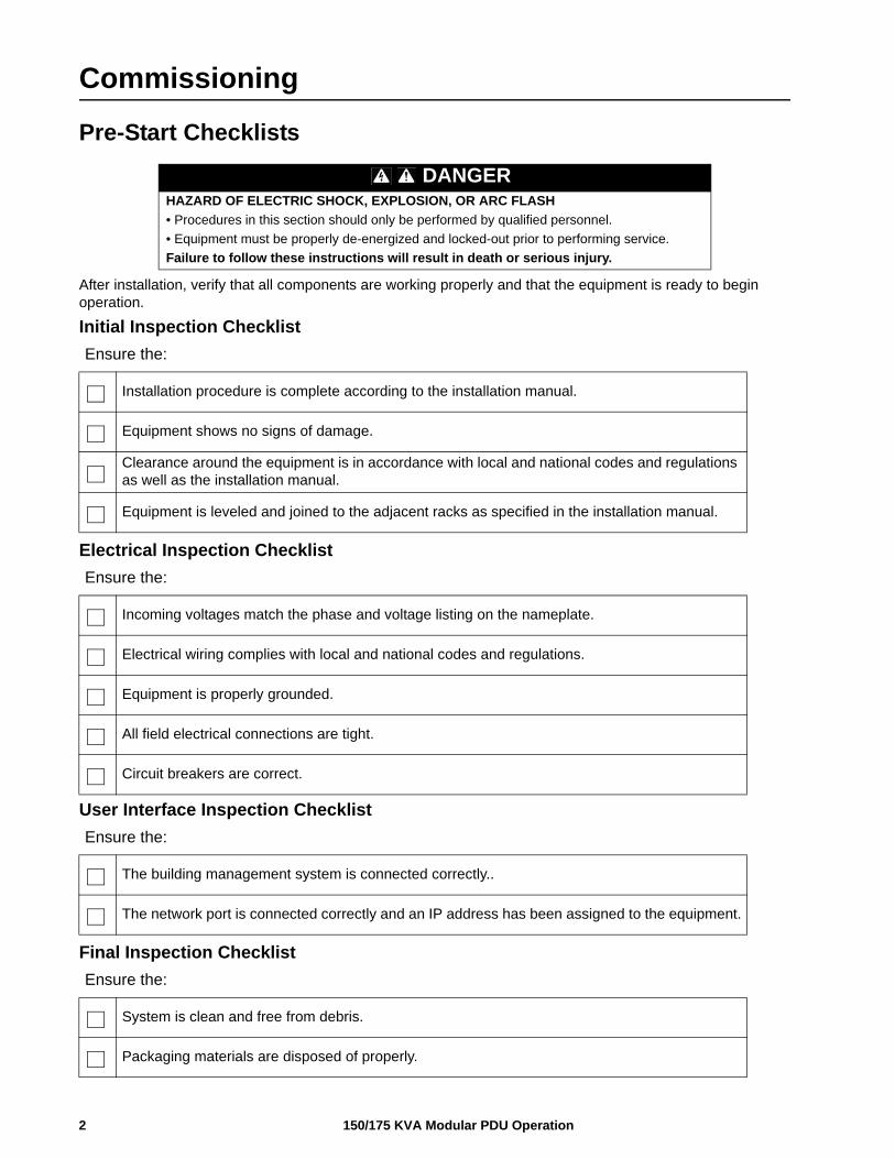
After installation, verify that all components are working properly and that the equipment is ready to begin operation.
Initial Inspection Checklist
Electrical Inspection Checklist
of
User Interface Inspection Checklist
Final Inspection Checklist
DANGERHAZARD OF ELECTRIC SHOCK, EXPLOSION, OR ARC FLASH
• Procedures in this section should only be performed by qualified personnel.
• Equipment must be properly de-energized and locked-out prior to performing service.
Failure to follow these instructions will result in death or serious injury.
Ensure the:
Installation procedure is complete according to the installation manual.
Equipment shows no signs of damage.
Clearance around the equipment is in accordance with local and national codes and regulations as well as the installation manual.
Equipment is leveled and joined to the adjacent racks as specified in the installation manual.
Ensure the:
Incoming voltages match the phase and voltage listing on the nameplate.
Electrical wiring complies with local and national codes and regulations.
Equipment is properly grounded.
All field electrical connections are tight.
Circuit breakers are correct.
Ensure the:
The building management system is connected correctly..
The network port is connected correctly and an IP address has been assigned to the equipment.
Ensure the:
System is clean and free from debris.
Packaging materials are disposed of properly.
150/175 KVA Modular PDU Operation2
3150/175 KVA Modular PDU Operation
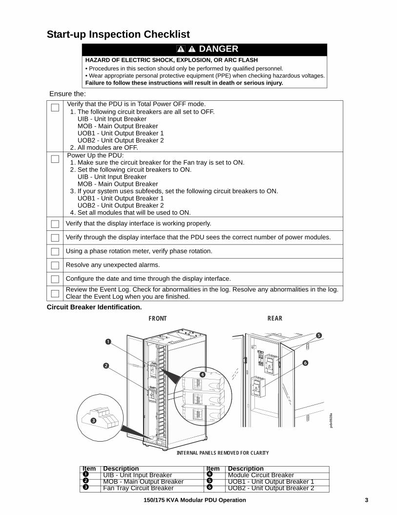
Start-up Inspection Checklist
Circuit Breaker Identification.
DANGERHAZARD OF ELECTRIC SHOCK, EXPLOSION, OR ARC FLASH
• Procedures in this section should only be performed by qualified personnel.• Wear appropriate personal protective equipment (PPE) when checking hazardous voltages.Failure to follow these instructions will result in death or serious injury.
Ensure the:
Verify that the PDU is in Total Power OFF mode. 1. The following circuit breakers are all set to OFF.
UIB - Unit Input BreakerMOB - Main Output BreakerUOB1 - Unit Output Breaker 1UOB2 - Unit Output Breaker 2
2. All modules are OFF.Power Up the PDU:1. Make sure the circuit breaker for the Fan tray is set to ON.2. Set the following circuit breakers to ON.
UIB - Unit Input BreakerMOB - Main Output Breaker
3. If your system uses subfeeds, set the following circuit breakers to ON.UOB1 - Unit Output Breaker 1UOB2 - Unit Output Breaker 2
4. Set all modules that will be used to ON.
Verify that the display interface is working properly.
Verify through the display interface that the PDU sees the correct number of power modules.
Using a phase rotation meter, verify phase rotation.
Resolve any unexpected alarms.
Configure the date and time through the display interface.
Review the Event Log. Check for abnormalities in the log. Resolve any abnormalities in the log. Clear the Event Log when you are finished.
Item Description Item Description UIB - Unit Input Breaker Module Circuit Breaker MOB - Main Output Breaker UOB1 - Unit Output Breaker 1 Fan Tray Circuit Breaker UOB2 - Unit Output Breaker 2
pd
x08
37a
pd
x09
28a
FRONT REAR
INTERNAL PANELS REMOVED FOR CLARITY
Operation
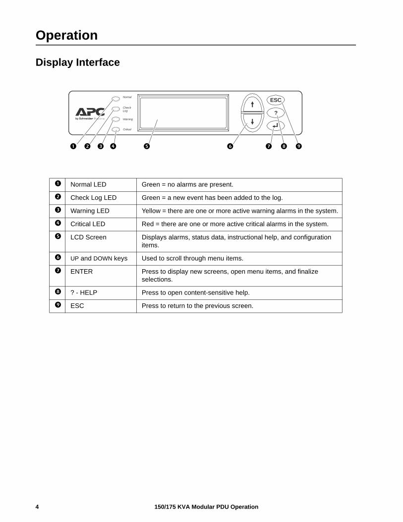
Display Interface
Normal LED Green = no alarms are present.
Check Log LED Green = a new event has been added to the log.
Warning LED Yellow = there are one or more active warning alarms in the system.
Critical LED Red = there are one or more active critical alarms in the system.
LCD Screen Displays alarms, status data, instructional help, and configuration items.
UP and DOWN keys Used to scroll through menu items.
ENTER Press to display new screens, open menu items, and finalize selections.
? - HELP Press to open content-sensitive help.
ESC Press to return to the previous screen.
ESC
?
Normal
CheckLog
Warning
Critical
150/175 KVA Modular PDU Operation4
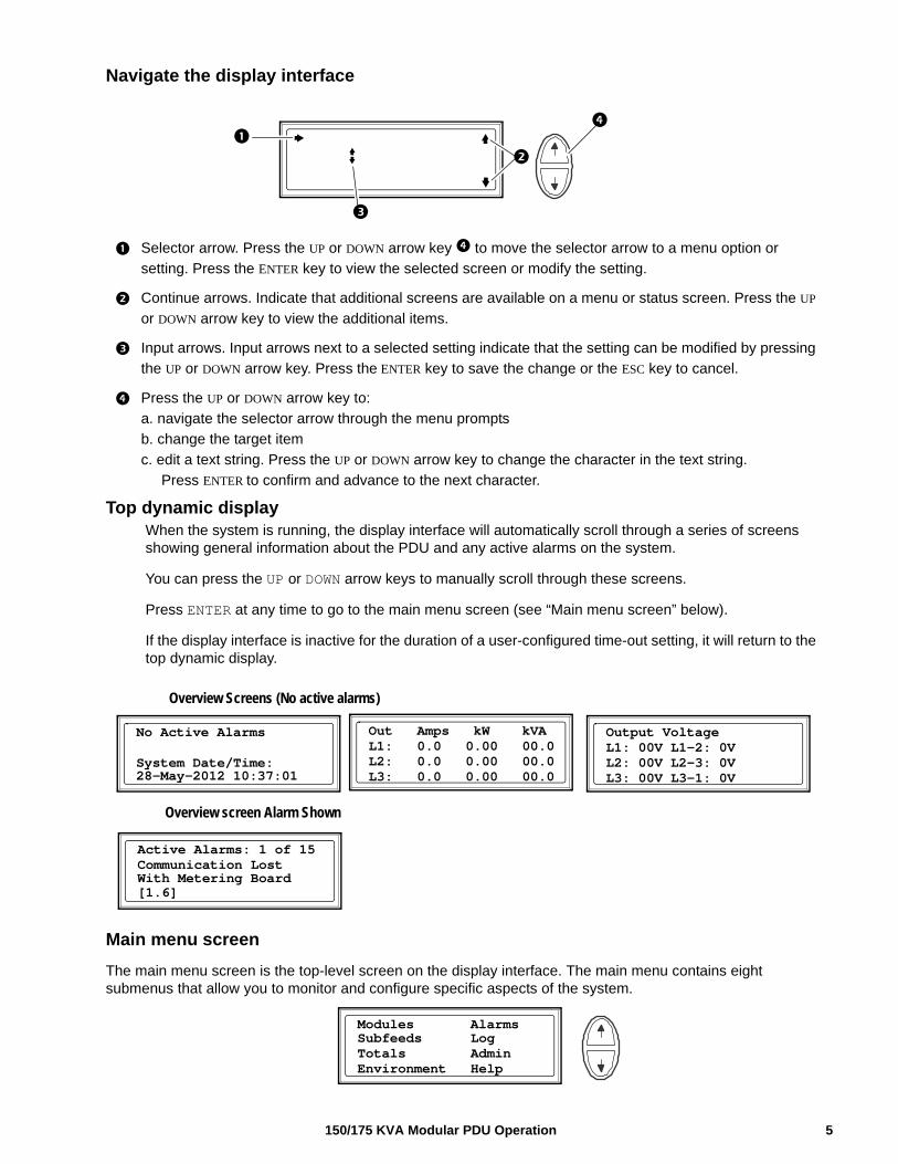
Navigate the display interface
Selector arrow. Press the UP or DOWN arrow key to move the selector arrow to a menu option or
setting. Press the ENTER key to view the selected screen or modify the setting.
Continue arrows. Indicate that additional screens are available on a menu or status screen. Press the UP
or DOWN arrow key to view the additional items.
Input arrows. Input arrows next to a selected setting indicate that the setting can be modified by pressing
the UP or DOWN arrow key. Press the ENTER key to save the change or the ESC key to cancel.
Press the UP or DOWN arrow key to:
a. navigate the selector arrow through the menu prompts
b. change the target item
c. edit a text string. Press the UP or DOWN arrow key to change the character in the text string.
Press ENTER to confirm and advance to the next character.
Top dynamic display When the system is running, the display interface will automatically scroll through a series of screens showing general information about the PDU and any active alarms on the system.
You can press the UP or DOWN arrow keys to manually scroll through these screens.
Press ENTER at any time to go to the main menu screen (see “Main menu screen” below).
If the display interface is inactive for the duration of a user-configured time-out setting, it will return to the top dynamic display.
Main menu screen
The main menu screen is the top-level screen on the display interface. The main menu contains eight submenus that allow you to monitor and configure specific aspects of the system.
Active Alarms: 1 of 15
With Metering Board[1.6]
Overview Screens (No active alarms)
No Active Alarms
System Date/Time:28-May-2012 10:37:01
Output VoltageL1: 00V L1-2: 0VL2: 00V L2-3: 0V
Communication Lost
Overview screen Alarm Shown
Out Amps kW kVAL1: 0.0 0.00 00.0L2: 0.0 0.00 00.0L3: 0.0 0.00 00.0 L3: 00V L3-1: 0V
Modules Alarms Subfeeds Log
Environment HelpTotals Admin
5150/175 KVA Modular PDU Operation
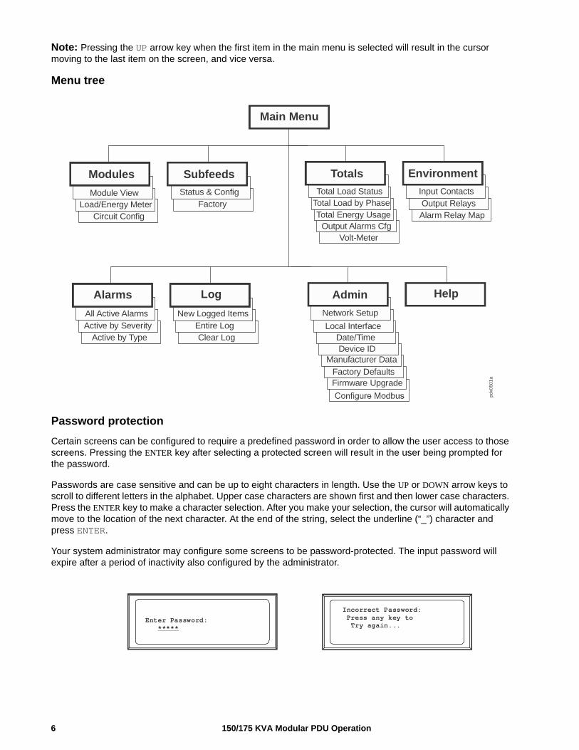
Note: Pressing the UP arrow key when the first item in the main menu is selected will result in the cursor moving to the last item on the screen, and vice versa.
Menu tree
Password protection
Certain screens can be configured to require a predefined password in order to allow the user access to those screens. Pressing the ENTER key after selecting a protected screen will result in the user being prompted for the password.
Passwords are case sensitive and can be up to eight characters in length. Use the UP or DOWN arrow keys to scroll to different letters in the alphabet. Upper case characters are shown first and then lower case characters. Press the ENTER key to make a character selection. After you make your selection, the cursor will automatically move to the location of the next character. At the end of the string, select the underline (“_”) character and press ENTER.
Your system administrator may configure some screens to be password-protected. The input password will expire after a period of inactivity also configured by the administrator.
Input ContactsOutput RelaysAlarm Relay Map
Total Load StatusTotal Load by PhaseTotal Energy Usage
Status & ConfigFactory
Main Menu
Modules Subfeeds Totals Environment
Date/TimeFactory DefaultsFirmware Upgrade
Network Setup
Local InterfaceDate/TimeDevice ID
Manufacturer Data
New Logged ItemsEntire LogClear Log
All Active AlarmsActive by Severity
Active by Type
HelpAdminLogAlarms
Module ViewLoad/Energy Meter
Circuit ConfigOutput Alarms Cfg
Volt-Meter
pdx0
501
a
Incorrect Password: Press any key to Try again...
Enter Password: *****
150/175 KVA Modular PDU Operation6
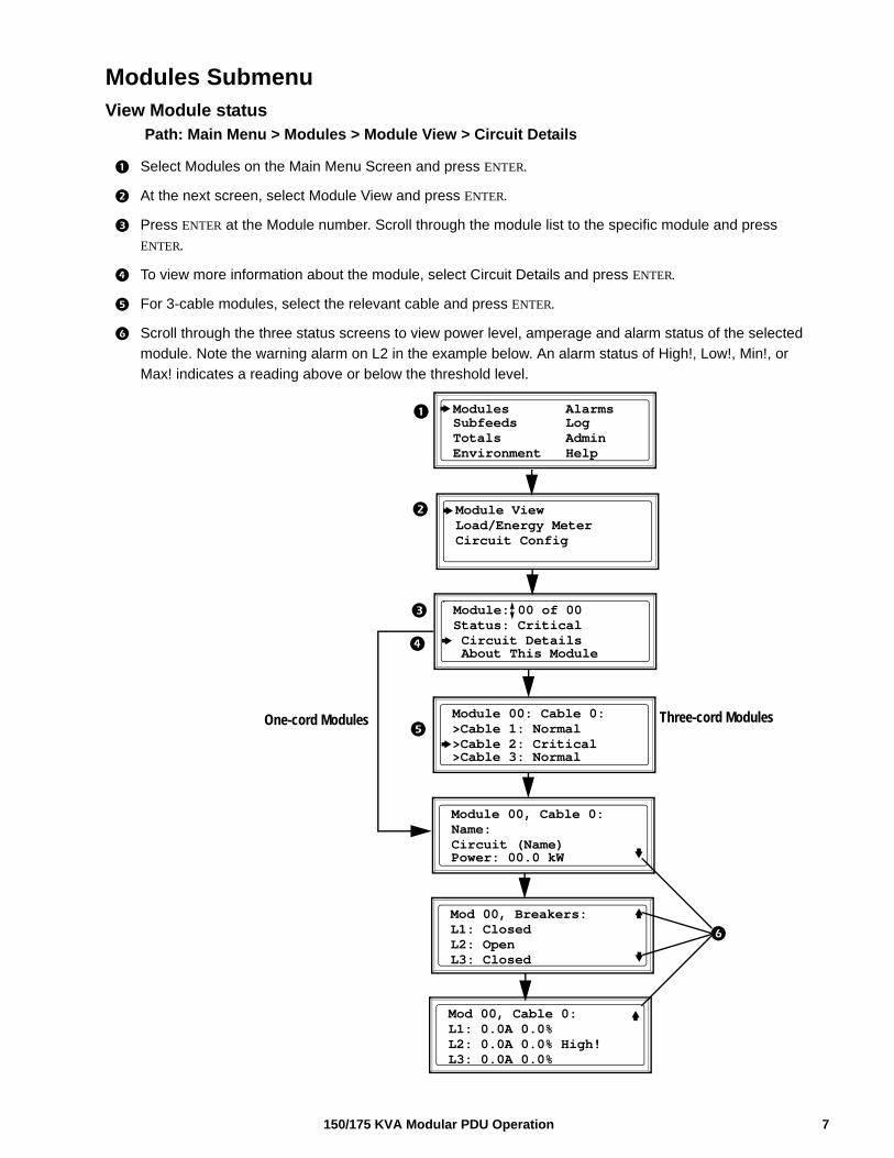
Modules SubmenuView Module status
Path: Main Menu > Modules > Module View > Circuit Details
Select Modules on the Main Menu Screen and press ENTER.
At the next screen, select Module View and press ENTER.
Press ENTER at the Module number. Scroll through the module list to the specific module and press
ENTER.
To view more information about the module, select Circuit Details and press ENTER.
For 3-cable modules, select the relevant cable and press ENTER.
Scroll through the three status screens to view power level, amperage and alarm status of the selected
module. Note the warning alarm on L2 in the example below. An alarm status of High!, Low!, Min!, or
Max! indicates a reading above or below the threshold level.
Module: 00 of 00Status: Critical Circuit Details About This Module
Module 00: Cable 0:>Cable 1: Normal>Cable 2: Critical>Cable 3: Normal
Module 00, Cable 0:Name:Circuit (Name)Power: 00.0 kW
Mod 00, Breakers:L1: ClosedL2: OpenL3: Closed
Mod 00, Cable 0:L1: 0.0A 0.0%L2: 0.0A 0.0% High!L3: 0.0A 0.0%
One-cord Modules Three-cord Modules
Module ViewLoad/Energy MeterCircuit Config
Modules Alarms Subfeeds Log
Environment HelpTotals Admin
7150/175 KVA Modular PDU Operation
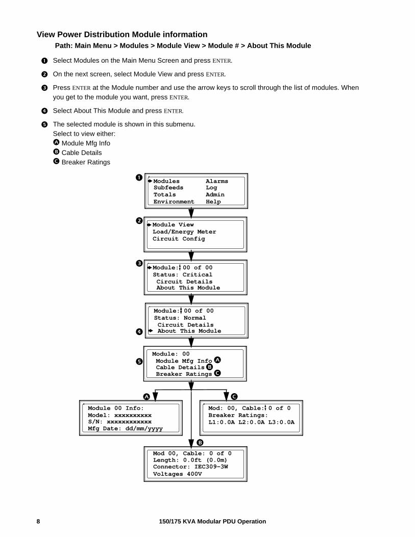
View Power Distribution Module informationPath: Main Menu > Modules > Module View > Module # > About This Module
Select Modules on the Main Menu Screen and press ENTER.
On the next screen, select Module View and press ENTER.
Press ENTER at the Module number and use the arrow keys to scroll through the list of modules. When
you get to the module you want, press ENTER.
Select About This Module and press ENTER.
The selected module is shown in this submenu.
Select to view either:
Module Mfg Info
Cable Details
Breaker Ratings
Module: 00 Module Mfg Info Cable Details Breaker Ratings
Module 00 Info:Model: xxxxxxxxxx
Mod: 00, Cable: 0 of 0Breaker Ratings:L1:0.0A L2:0.0A L3:0.0A
Module: 00 of 00Status: Normal Circuit Details About This Module
S/N: xxxxxxxxxxxxMfg Date: dd/mm/yyyy
Module: 00 of 00Status: Critical Circuit Details About This Module
Module ViewLoad/Energy MeterCircuit Config
Modules Alarms Subfeeds Log
Environment HelpTotals Admin
Mod 00, Cable: 0 of 0Length: 0.0ft (0.0m)Connector: IEC309-3WVoltages 400V
150/175 KVA Modular PDU Operation8
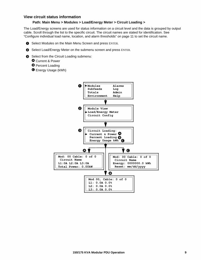
View circuit status informationPath: Main Menu > Modules > Load/Energy Meter > Circuit Loading >
The Load/Energy screens are used for status information on a circuit level and the data is grouped by output cable. Scroll through the list to the specific circuit. The circuit names are stated for identification. See “Configure individual load name, location, and alarm thresholds” on page 11 to set the circuit name.
Select Modules on the Main Menu Screen and press ENTER.
Select Load/Energy Meter on the submenu screen and press ENTER.
Select from the Circuit Loading submenu:
Current & Power
Percent Loading
Energy Usage (kWh)
Circuit Loading: Current & Power Percent Loading Energy Usage kWh
Mod: 00 Cable: 0 of 0 Circuit NameL1:0A L2:0A L3:0A
Mod 00, Cable: 0 of 0L1: 0.0A 0.0%L2: 0.0A 0.0%L3: 0.0A 0.0%
Mod: 00 Cable: 0 of 0 Circuit NameEnergy: 0000000.0 kWh
Total Power: 0.00kW Reset: mm/dd/yyyy
Module ViewLoad/Energy MeterCircuit Config
Modules Alarms Subfeeds Log
Environment HelpTotals Admin
9150/175 KVA Modular PDU Operation
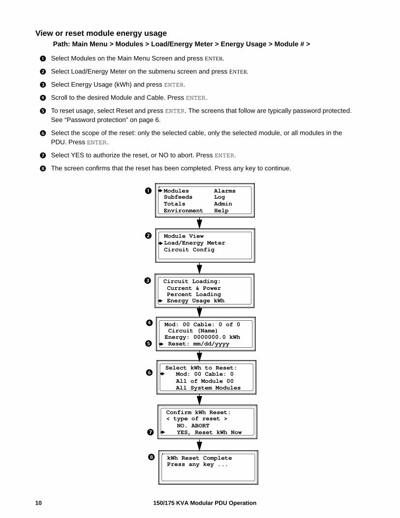
View or reset module energy usagePath: Main Menu > Modules > Load/Energy Meter > Energy Usage > Module # >
Select Modules on the Main Menu Screen and press ENTER.
Select Load/Energy Meter on the submenu screen and press ENTER.
Select Energy Usage (kWh) and press ENTER.
Scroll to the desired Module and Cable. Press ENTER.
To reset usage, select Reset and press ENTER. The screens that follow are typically password protected.
See “Password protection” on page 6.
Select the scope of the reset: only the selected cable, only the selected module, or all modules in the
PDU. Press ENTER.
Select YES to authorize the reset, or NO to abort. Press ENTER.
The screen confirms that the reset has been completed. Press any key to continue.
Circuit Loading: Current & Power Percent Loading Energy Usage kWh
Select kWh to Reset: Mod: 00 Cable: 0 All of Module 00
Mod: 00 Cable: 0 of 0 Circuit (Name)Energy: 0000000.0 kWh
All System Modules
Reset: mm/dd/yyyy
Confirm kWh Reset:< type of reset > NO. ABORT YES, Reset kWh Now
kWh Reset CompletePress any key ...
Module ViewLoad/Energy MeterCircuit Config
Modules Alarms Subfeeds Log
Environment HelpTotals Admin
150/175 KVA Modular PDU Operation10
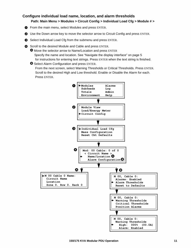
Configure individual load name, location, and alarm thresholds Path: Main Menu > Modules > Circuit Config > Individual Load Cfg > Module # >
From the main menu, select Modules and press ENTER.
Use the Down arrow key to move the selector arrow to Circuit Config and press ENTER.
Select Individual Load Cfg from the submenu and press ENTER.
Scroll to the desired Module and Cable and press ENTER.
Move the selector arrow to Name/Location and press ENTER
Specify the name and location. See “Navigate the display interface” on page 5
for instructions for entering text strings. Press ENTER when the text string is finished.
Select Alarm Configuration and press ENTER.
From the next screen, select Warning Thresholds or Critical Thresholds. Press ENTER.
Scroll to the desired High and Low threshold. Enable or Disable the Alarm for each.
Press ENTER.
Individual Load CfgMass ConfigurationReset Ckt Defaults
Mod: 00 Cable: 0 of 0 < Circuit Name > Name/Location
Alarm Configuration
Module ViewLoad/Energy MeterCircuit Config
Modules Alarms Subfeeds Log
Environment HelpTotals Admin
M 00 Cable 0 Name: Circuit Name Location Zone 0. Row 0. Rack 0
M 00, Cable 0: Alarms: Enabled Alarm Thresholds Reset to Defaults
M 00, Cable 0: Warning Thresholds Critical Thresholds Position Alarms
M 00, Cable 0: Warning Thresholds High: 000% (00.0A) Alarm: Enabled
11150/175 KVA Modular PDU Operation
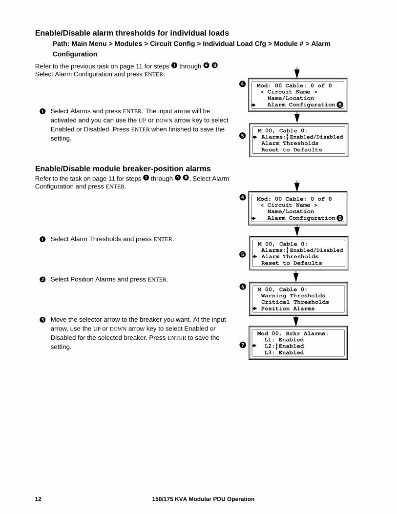
Enable/Disable alarm thresholds for individual loadsPath: Main Menu > Modules > Circuit Config > Individual Load Cfg > Module # > Alarm
Configuration
Refer to the previous task on page 11 for steps through . Select Alarm Configuration and press ENTER.
Select Alarms and press ENTER. The input arrow will be
activated and you can use the UP or DOWN arrow key to select
Enabled or Disabled. Press ENTER when finished to save the
setting.
Enable/Disable module breaker-position alarmsRefer to the task on page 11 for steps through . Select Alarm Configuration and press ENTER.
Select Alarm Thresholds and press ENTER.
Select Position Alarms and press ENTER.
Move the selector arrow to the breaker you want. At the input
arrow, use the UP or DOWN arrow key to select Enabled or
Disabled for the selected breaker. Press ENTER to save the
setting.
Mod: 00 Cable: 0 of 0 < Circuit Name > Name/Location Alarm Configuration
M 00, Cable 0: Alarms: Enabled/Disabled Alarm Thresholds Reset to Defaults
Mod: 00 Cable: 0 of 0 < Circuit Name > Name/Location Alarm Configuration
M 00, Cable 0: Alarms: Enabled/Disabled Alarm Thresholds Reset to Defaults
M 00, Cable 0: Warning Thresholds Critical Thresholds Position Alarms
Mod 00, Brkr Alarms: L1: Enabled L2: Enabled L3: Enabled
150/175 KVA Modular PDU Operation12
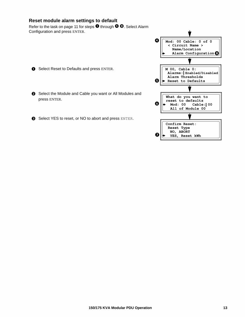
Reset module alarm settings to default Refer to the task on page 11 for steps through . Select Alarm Configuration and press ENTER.
Select Reset to Defaults and press ENTER.
Select the Module and Cable you want or All Modules and
press ENTER.
Select YES to reset, or NO to abort and press ENTER.
Mod: 00 Cable: 0 of 0 < Circuit Name > Name/Location Alarm Configuration
M 00, Cable 0: Alarms: Enabled/Disabled Alarm Thresholds Reset to Defaults
What do you want toreset to defaults Mod: 00 Cable: 00 All of Module 00
Confirm Reset: Reset Type NO, ABORT YES, Reset kWh
13150/175 KVA Modular PDU Operation
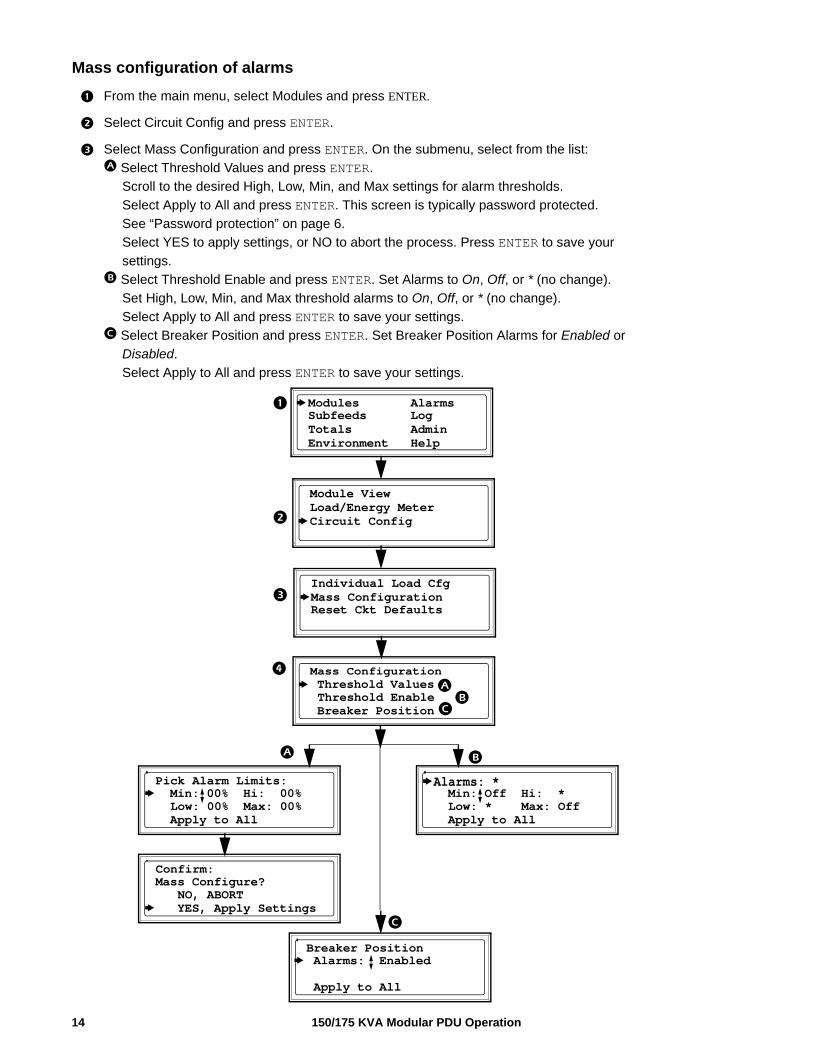
Mass configuration of alarms
From the main menu, select Modules and press ENTER.
Select Circuit Config and press ENTER.
Select Mass Configuration and press ENTER. On the submenu, select from the list:
Select Threshold Values and press ENTER.
Scroll to the desired High, Low, Min, and Max settings for alarm thresholds.
Select Apply to All and press ENTER. This screen is typically password protected.
See “Password protection” on page 6.
Select YES to apply settings, or NO to abort the process. Press ENTER to save your
settings.
Select Threshold Enable and press ENTER. Set Alarms to On, Off, or * (no change).
Set High, Low, Min, and Max threshold alarms to On, Off, or * (no change).
Select Apply to All and press ENTER to save your settings.
Select Breaker Position and press ENTER. Set Breaker Position Alarms for Enabled or
Disabled.
Select Apply to All and press ENTER to save your settings.
Individual Load CfgMass ConfigurationReset Ckt Defaults
Mass Configuration Threshold Values Threshold Enable
Breaker Position
Module ViewLoad/Energy MeterCircuit Config
Modules Alarms Subfeeds Log
Environment HelpTotals Admin
Pick Alarm Limits: Min: 00% Hi: 00% Low: 00% Max: 00% Apply to All
Confirm:Mass Configure? NO, ABORT YES, Apply Settings
Alarms: * Min: Off Hi: * Low: * Max: Off Apply to All
Breaker Position Alarms: Enabled Apply to All
150/175 KVA Modular PDU Operation14
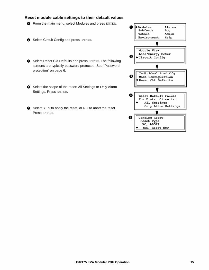
Reset module cable settings to their default values
From the main menu, select Modules and press ENTER.
Select Circuit Config and press ENTER.
Select Reset Ckt Defaults and press ENTER. The following
screens are typically password protected. See “Password
protection” on page 6.
Select the scope of the reset: All Settings or Only Alarm
Settings. Press ENTER.
Select YES to apply the reset, or NO to abort the reset.
Press ENTER.
Individual Load CfgMass ConfigurationReset Ckt Defaults
Reset Default FaluesFor Distr. Circuits: All Settings
Only Alarm Settings
Module ViewLoad/Energy MeterCircuit Config
Modules Alarms Subfeeds Log
Environment HelpTotals Admin
Confirm Reset: Reset Type NO, ABORT YES, Reset Now
15150/175 KVA Modular PDU Operation
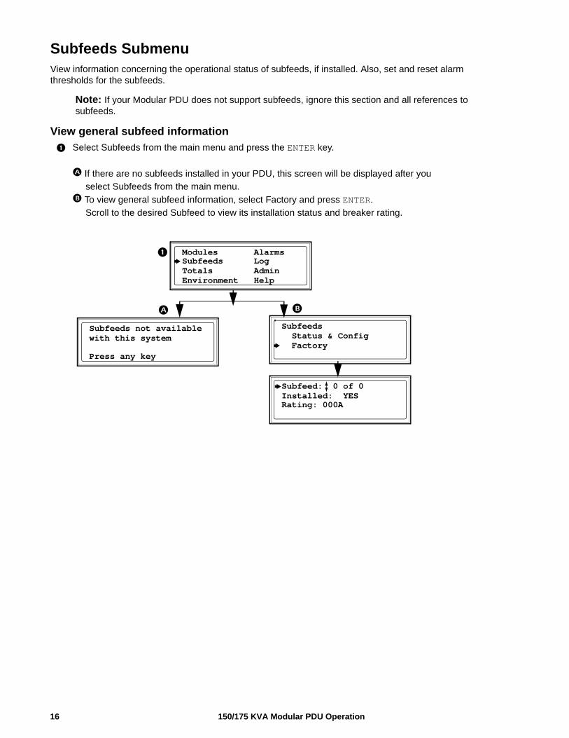
Subfeeds SubmenuView information concerning the operational status of subfeeds, if installed. Also, set and reset alarm thresholds for the subfeeds.
Note: If your Modular PDU does not support subfeeds, ignore this section and all references to subfeeds.
View general subfeed information
Select Subfeeds from the main menu and press the ENTER key.
If there are no subfeeds installed in your PDU, this screen will be displayed after you
select Subfeeds from the main menu.
To view general subfeed information, select Factory and press ENTER.
Scroll to the desired Subfeed to view its installation status and breaker rating.
Subfeed: 0 of 0Installed: YESRating: 000A
Subfeeds not availablewith this system
Modules Alarms Subfeeds Log
Environment HelpTotals Admin
Subfeeds Status & Config Factory
Press any key
150/175 KVA Modular PDU Operation16
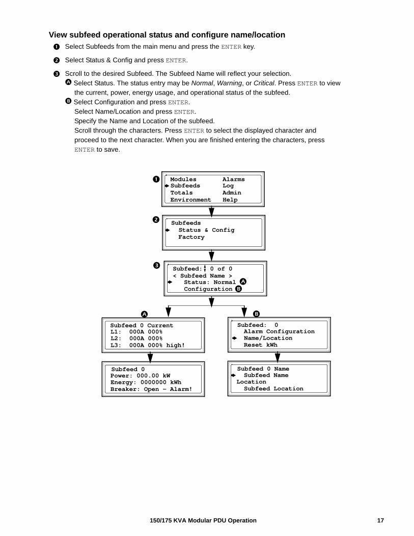
View subfeed operational status and configure name/location
Select Subfeeds from the main menu and press the ENTER key.
Select Status & Config and press ENTER.
Scroll to the desired Subfeed. The Subfeed Name will reflect your selection.
Select Status. The status entry may be Normal, Warning, or Critical. Press ENTER to view
the current, power, energy usage, and operational status of the subfeed.
Select Configuration and press ENTER.
Select Name/Location and press ENTER.
Specify the Name and Location of the subfeed.
Scroll through the characters. Press ENTER to select the displayed character and
proceed to the next character. When you are finished entering the characters, press
ENTER to save.
L1: 000A 000%L2: 000A 000%L3: 000A 000% high!
Subfeeds Status & Config Factory
Subfeed: 0 of 0< Subfeed Name > Status: Normal Configuration
Subfeed 0 Current Alarm Configuration Name/Location Reset kWh
Subfeed: 0
Power: 000.00 kWEnergy: 0000000 kWhBreaker: Open - Alarm!
Subfeed 0
Subfeed NameLocation Subfeed Location
Subfeed 0 Name
Modules Alarms Subfeeds Log
Environment HelpTotals Admin
17150/175 KVA Modular PDU Operation
150/175 KVA Modular PDU Operation18
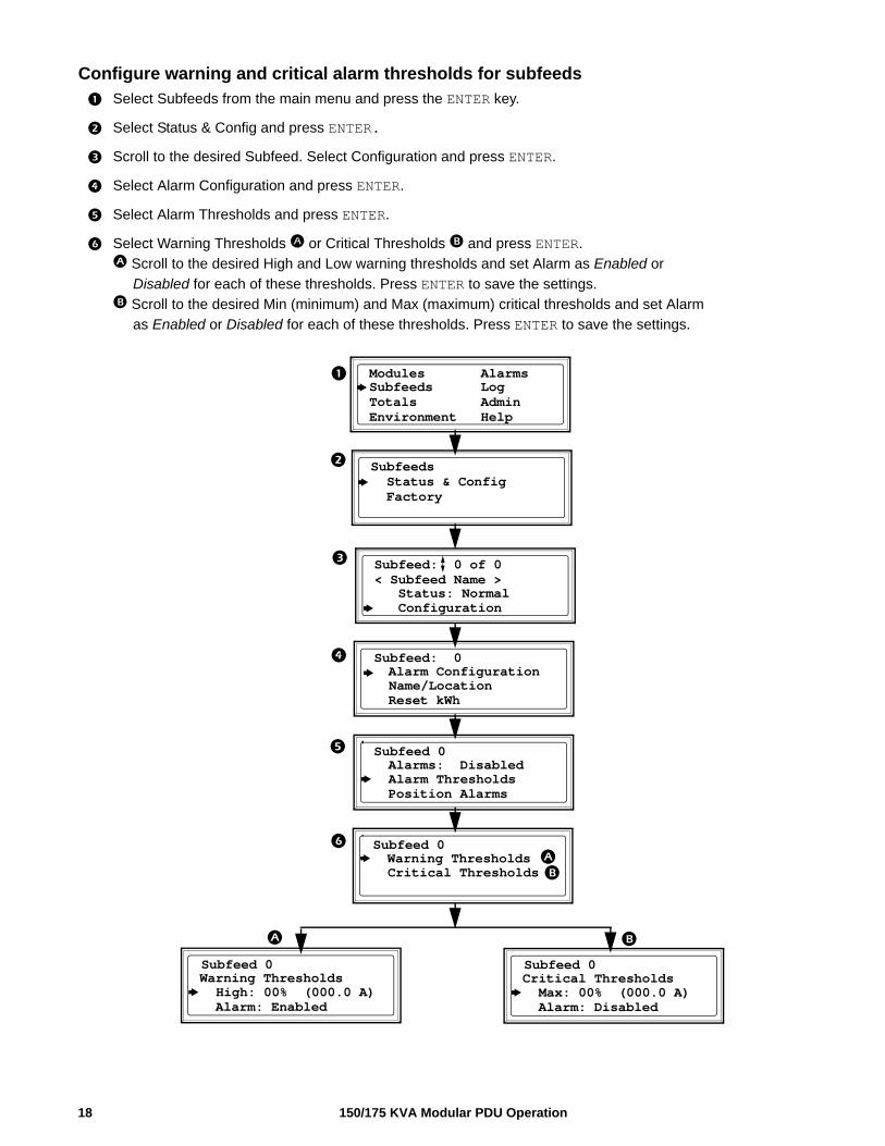
Configure warning and critical alarm thresholds for subfeeds
Select Subfeeds from the main menu and press the ENTER key.
Select Status & Config and press ENTER.
Scroll to the desired Subfeed. Select Configuration and press ENTER.
Select Alarm Configuration and press ENTER.
Select Alarm Thresholds and press ENTER.
Select Warning Thresholds or Critical Thresholds and press ENTER.
Scroll to the desired High and Low warning thresholds and set Alarm as Enabled or
Disabled for each of these thresholds. Press ENTER to save the settings.
Scroll to the desired Min (minimum) and Max (maximum) critical thresholds and set Alarm
as Enabled or Disabled for each of these thresholds. Press ENTER to save the settings.
Subfeeds Status & Config Factory
Subfeed: 0 of 0< Subfeed Name > Status: Normal Configuration
Alarm Configuration Name/Location Reset kWh
Subfeed: 0
Alarms: Disabled Alarm Thresholds Position Alarms
Subfeed 0
Modules Alarms Subfeeds Log
Environment HelpTotals Admin
Warning Thresholds Critical Thresholds
Subfeed 0
Warning Thresholds High: 00% (000.0 A) Alarm: Enabled
Subfeed 0
Critical Thresholds Max: 00% (000.0 A) Alarm: Disabled
Subfeed 0
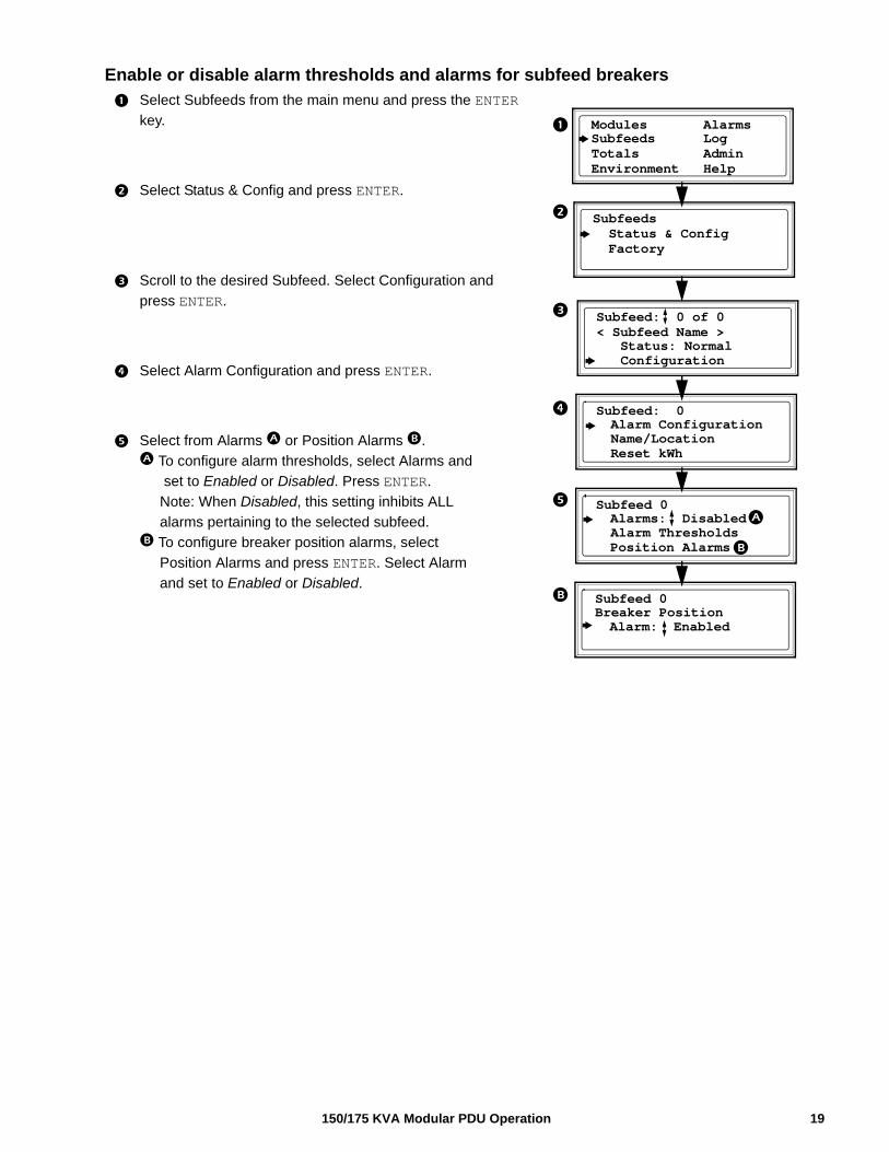
Enable or disable alarm thresholds and alarms for subfeed breakers
Select Subfeeds from the main menu and press the ENTER
key.
Select Status & Config and press ENTER.
Scroll to the desired Subfeed. Select Configuration and
press ENTER.
Select Alarm Configuration and press ENTER.
Select from Alarms or Position Alarms .
To configure alarm thresholds, select Alarms and
set to Enabled or Disabled. Press ENTER.
Note: When Disabled, this setting inhibits ALL
alarms pertaining to the selected subfeed.
To configure breaker position alarms, select
Position Alarms and press ENTER. Select Alarm
and set to Enabled or Disabled.
Subfeeds Status & Config Factory
Subfeed: 0 of 0< Subfeed Name > Status: Normal Configuration
Alarm Configuration Name/Location Reset kWh
Subfeed: 0
Alarms: Disabled Alarm Thresholds Position Alarms
Subfeed 0
Modules Alarms Subfeeds Log
Environment HelpTotals Admin
Breaker Position Alarm: Enabled
Subfeed 0
19150/175 KVA Modular PDU Operation
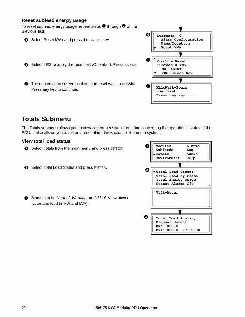
Reset subfeed energy usageTo reset subfeed energy usage, repeat steps through of the previous task.
Select Reset kWh and press the ENTER key.
Select YES to apply the reset, or NO to abort. Press ENTER.
The confirmation screen confirms the reset was successful.
Press any key to continue.
Totals SubmenuThe Totals submenu allows you to view comprehensive information concerning the operational status of the PDU. It also allows you to set and reset alarm thresholds for the entire system.
View total load status
Select Totals from the main menu and press ENTER.
Select Total Load Status and press ENTER.
Status can be Normal, Warning, or Critical. View power
factor and load (in kW and kVA).
Alarm Configuration Name/Location Reset kWh
Subfeed: 0
now resetPress any key . . .
KiloWatt-Hours
Confirm Reset:Subfeed 0 kWh NO, ABORT YES, Reset Now
Total Load StatusTotal Load by PhaseTotal Energy Usage
Volt-Meter
Status: NormalkW: 000.0kVA: 000.0 PF: 0.00
Total Load Summary
Modules Alarms Subfeeds Log
Environment HelpTotals Admin
Output Alarms Cfg
150/175 KVA Modular PDU Operation20
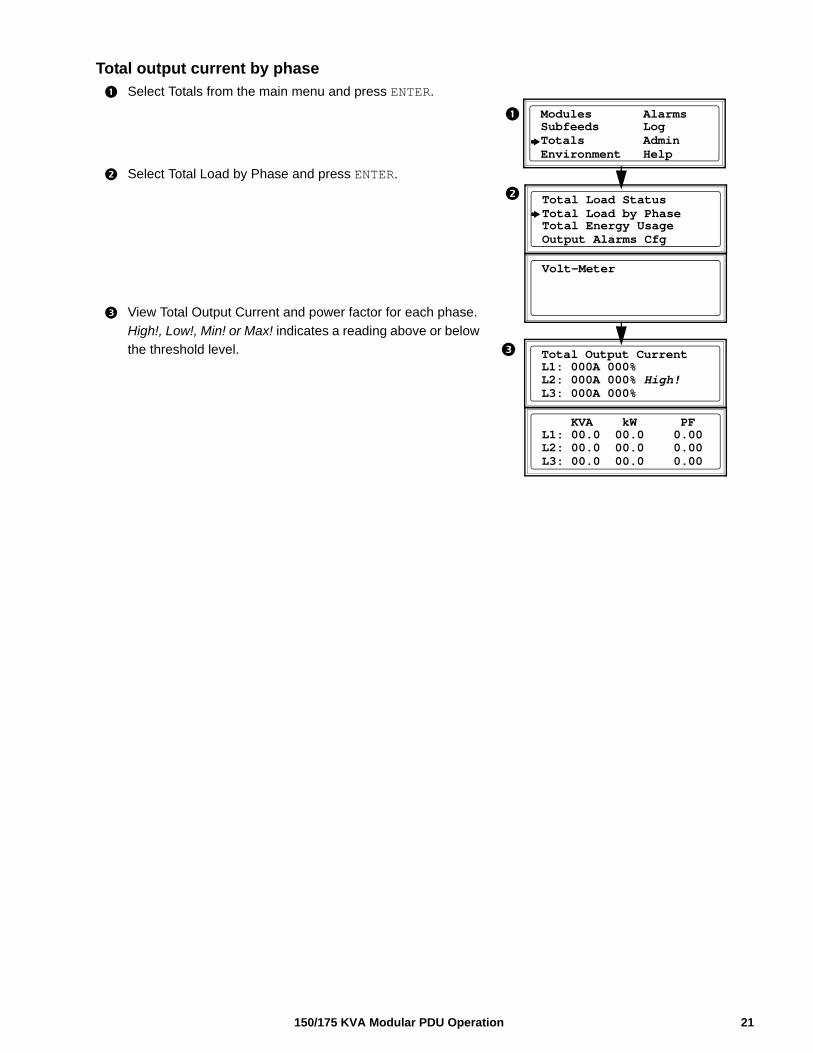
Total output current by phase
Select Totals from the main menu and press ENTER.
Select Total Load by Phase and press ENTER.
View Total Output Current and power factor for each phase.
High!, Low!, Min! or Max! indicates a reading above or below
the threshold level.
Total Load StatusTotal Load by PhaseTotal Energy Usage
Volt-Meter
L1: 000A 000%L2: 000A 000% High!L3: 000A 000%
Total Output Current
Modules Alarms Subfeeds Log
Environment HelpTotals Admin
Output Alarms Cfg
L1: 00.0 00.0 0.00L2: 00.0 00.0 0.00L3: 00.0 00.0 0.00
KVA kW PF
21150/175 KVA Modular PDU Operation
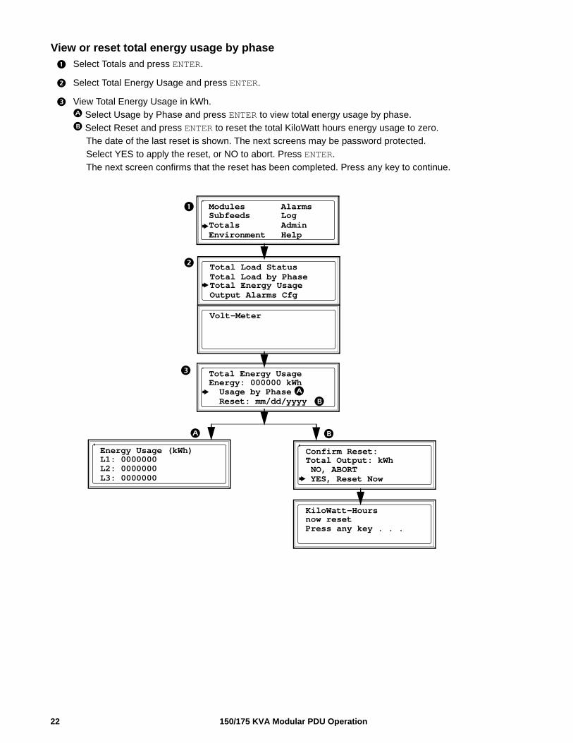
View or reset total energy usage by phase
Select Totals and press ENTER.
Select Total Energy Usage and press ENTER.
View Total Energy Usage in kWh.
Select Usage by Phase and press ENTER to view total energy usage by phase.
Select Reset and press ENTER to reset the total KiloWatt hours energy usage to zero.
The date of the last reset is shown. The next screens may be password protected.
Select YES to apply the reset, or NO to abort. Press ENTER.
The next screen confirms that the reset has been completed. Press any key to continue.
Total Load StatusTotal Load by PhaseTotal Energy Usage
Volt-Meter
Energy: 000000 kWh Usage by Phase Reset: mm/dd/yyyy
Total Energy Usage
Modules Alarms Subfeeds Log
Environment HelpTotals Admin
Output Alarms Cfg
L1: 0000000L2: 0000000L3: 0000000
Energy Usage (kWh)
now resetPress any key . . .
KiloWatt-Hours
Confirm Reset:Total Output: kWh NO, ABORT YES, Reset Now
150/175 KVA Modular PDU Operation22
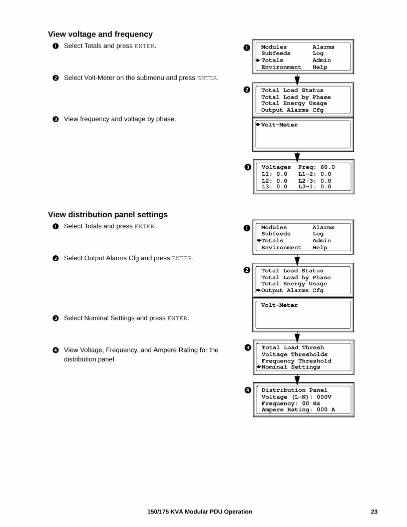
View voltage and frequency
Select Totals and press ENTER.
Select Volt-Meter on the submenu and press ENTER.
View frequency and voltage by phase.
View distribution panel settings
Select Totals and press ENTER.
Select Output Alarms Cfg and press ENTER.
Select Nominal Settings and press ENTER.
View Voltage, Frequency, and Ampere Rating for the
distribution panel.
Voltages Freq: 60.0
L3: 0.0 L3-1: 0.0
L1: 0.0 L1-2: 0.0L2: 0.0 L2-3: 0.0
Modules Alarms Subfeeds Log
Environment HelpTotals Admin
Total Load StatusTotal Load by PhaseTotal Energy Usage
Volt-Meter
Output Alarms Cfg
Total Load Thresh
Nominal Settings
Voltage Thresholds
Modules Alarms Subfeeds Log
Environment HelpTotals Admin
Total Load StatusTotal Load by PhaseTotal Energy Usage
Volt-Meter
Output Alarms Cfg
Frequency Threshold
Distribution Panel
Ampere Rating: 000 A
Voltage (L-N): 000VFrequency: 00 Hz
23150/175 KVA Modular PDU Operation
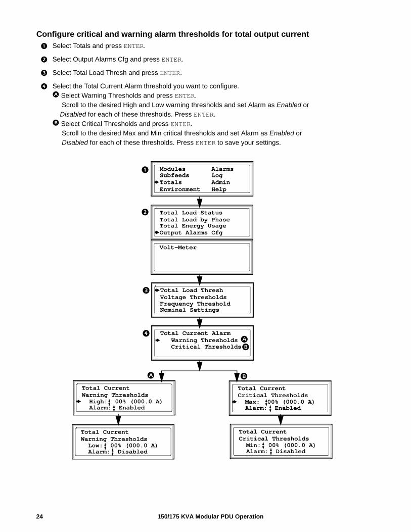
Configure critical and warning alarm thresholds for total output current
Select Totals and press ENTER.
Select Output Alarms Cfg and press ENTER.
Select Total Load Thresh and press ENTER.
Select the Total Current Alarm threshold you want to configure.
Select Warning Thresholds and press ENTER.
Scroll to the desired High and Low warning thresholds and set Alarm as Enabled or
Disabled for each of these thresholds. Press ENTER.
Select Critical Thresholds and press ENTER.
Scroll to the desired Max and Min critical thresholds and set Alarm as Enabled or
Disabled for each of these thresholds. Press ENTER to save your settings.
Total Load Thresh
Nominal Settings
Voltage Thresholds
Modules Alarms Subfeeds Log
Environment HelpTotals Admin
Total Load StatusTotal Load by PhaseTotal Energy Usage
Volt-Meter
Output Alarms Cfg
Frequency Threshold
Total Current Alarm Warning Thresholds Critical Thresholds
Total Current
Alarm: Enabled
Warning Thresholds High: 00% (000.0 A)
Total Current
Alarm: Enabled
Critical Thresholds Max: 00% (000.0 A)
Total Current
Alarm: Disabled
Critical Thresholds Min: 00% (000.0 A)
Total Current
Alarm: Disabled
Warning Thresholds Low: 00% (000.0 A)
150/175 KVA Modular PDU Operation24
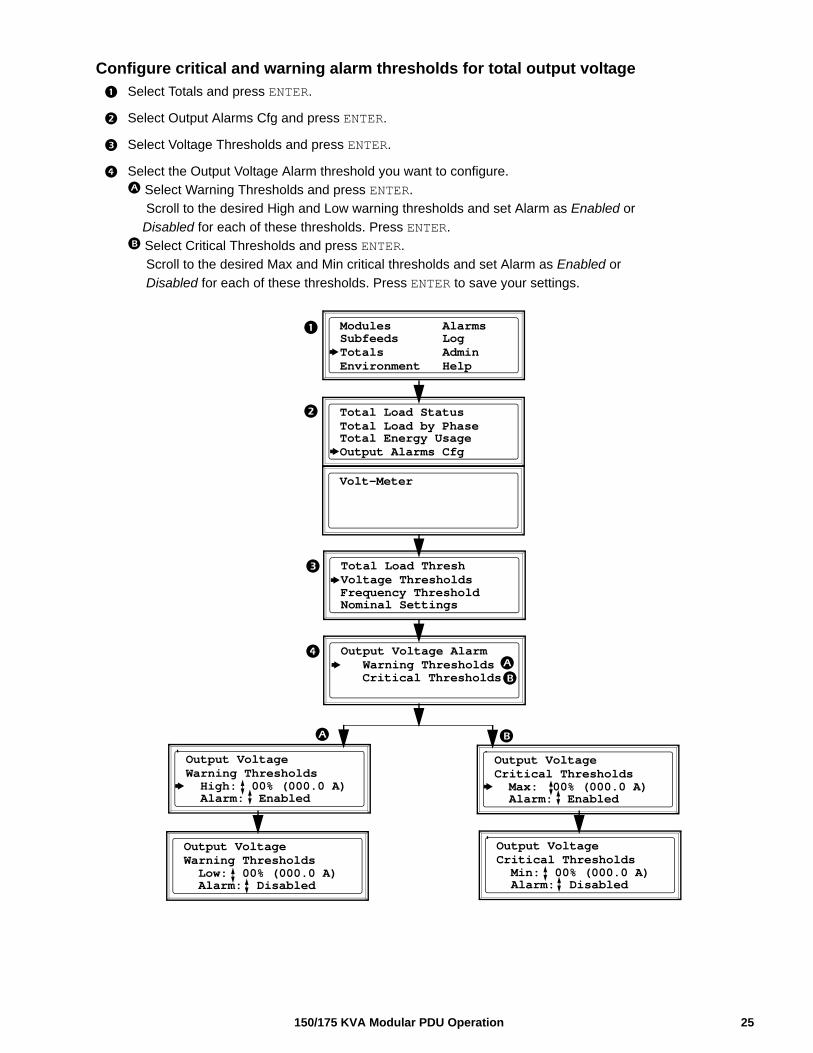
Configure critical and warning alarm thresholds for total output voltage
Select Totals and press ENTER.
Select Output Alarms Cfg and press ENTER.
Select Voltage Thresholds and press ENTER.
Select the Output Voltage Alarm threshold you want to configure.
Select Warning Thresholds and press ENTER.
Scroll to the desired High and Low warning thresholds and set Alarm as Enabled or
Disabled for each of these thresholds. Press ENTER.
Select Critical Thresholds and press ENTER.
Scroll to the desired Max and Min critical thresholds and set Alarm as Enabled or
Disabled for each of these thresholds. Press ENTER to save your settings.
Total Load Thresh
Nominal Settings
Voltage Thresholds
Modules Alarms Subfeeds Log
Environment HelpTotals Admin
Total Load StatusTotal Load by PhaseTotal Energy Usage
Volt-Meter
Output Alarms Cfg
Frequency Threshold
Output Voltage Alarm Warning Thresholds Critical Thresholds
Output Voltage
Alarm: Enabled
Warning Thresholds High: 00% (000.0 A)
Output Voltage
Alarm: Enabled
Critical Thresholds Max: 00% (000.0 A)
Output Voltage
Alarm: Disabled
Critical Thresholds Min: 00% (000.0 A)
Output Voltage
Alarm: Disabled
Warning Thresholds Low: 00% (000.0 A)
25150/175 KVA Modular PDU Operation
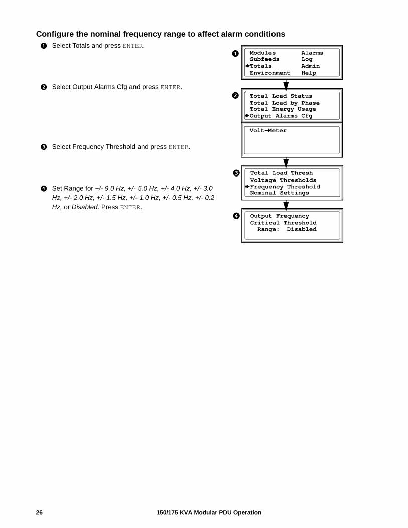
Configure the nominal frequency range to affect alarm conditions
Select Totals and press ENTER.
Select Output Alarms Cfg and press ENTER.
Select Frequency Threshold and press ENTER.
Set Range for +/- 9.0 Hz, +/- 5.0 Hz, +/- 4.0 Hz, +/- 3.0
Hz, +/- 2.0 Hz, +/- 1.5 Hz, +/- 1.0 Hz, +/- 0.5 Hz, +/- 0.2
Hz, or Disabled. Press ENTER.
Total Load Thresh
Nominal Settings
Voltage Thresholds
Modules Alarms Subfeeds Log
Environment HelpTotals Admin
Total Load StatusTotal Load by PhaseTotal Energy Usage
Volt-Meter
Output Alarms Cfg
Frequency Threshold
Output FrequencyCritical Threshold Range: Disabled
150/175 KVA Modular PDU Operation26
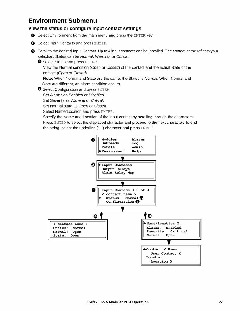
Environment SubmenuView the status or configure input contact settings
Select Environment from the main menu and press the ENTER key.
Select Input Contacts and press ENTER.
Scroll to the desired Input Contact. Up to 4 input contacts can be installed. The contact name reflects your
selection. Status can be Normal, Warning, or Critical.
Select Status and press ENTER.
View the Normal condition (Open or Closed) of the contact and the actual State of the
contact (Open or Closed).
Note: When Normal and State are the same, the Status is Normal. When Normal and
State are different, an alarm condition occurs.
Select Configuration and press ENTER.
Set Alarms as Enabled or Disabled.
Set Severity as Warning or Critical.
Set Normal state as Open or Closed.
Select Name/Location and press ENTER.
Specify the Name and Location of the input contact by scrolling through the characters.
Press ENTER to select the displayed character and proceed to the next character. To end
the string, select the underline (“_”) character and press ENTER.
Input Contact: 0 of 4
Configuration
< contact name >
Modules Alarms Subfeeds Log
Environment HelpTotals Admin
Input ContactsOutput RelaysAlarm Relay Map
Status: Normal
< contact name >
State: Open
Status: NormalNormal: Open
Name/Location X
Normal: Open
Alarms: EnabledSeverity: Critical
Contact X Name:
Location X
User Contact XLocation:
27150/175 KVA Modular PDU Operation
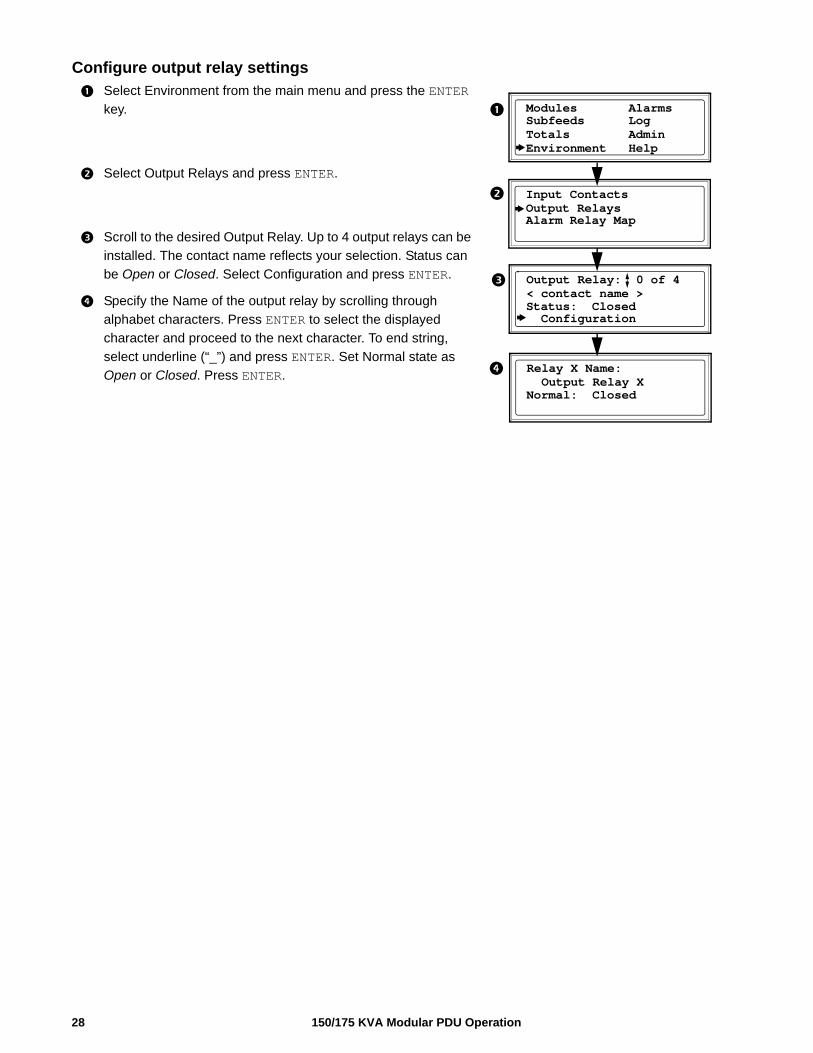
Configure output relay settings
Select Environment from the main menu and press the ENTER
key.
Select Output Relays and press ENTER.
Scroll to the desired Output Relay. Up to 4 output relays can be
installed. The contact name reflects your selection. Status can
be Open or Closed. Select Configuration and press ENTER.
Specify the Name of the output relay by scrolling through
alphabet characters. Press ENTER to select the displayed
character and proceed to the next character. To end string,
select underline (“_”) and press ENTER. Set Normal state as
Open or Closed. Press ENTER.
Output Relay: 0 of 4
Configuration
< contact name >
Modules Alarms Subfeeds Log
Environment HelpTotals Admin
Input ContactsOutput RelaysAlarm Relay Map
Status: Closed
Relay X Name: Output Relay XNormal: Closed
150/175 KVA Modular PDU Operation28
29150/175 KVA Modular PDU Operation
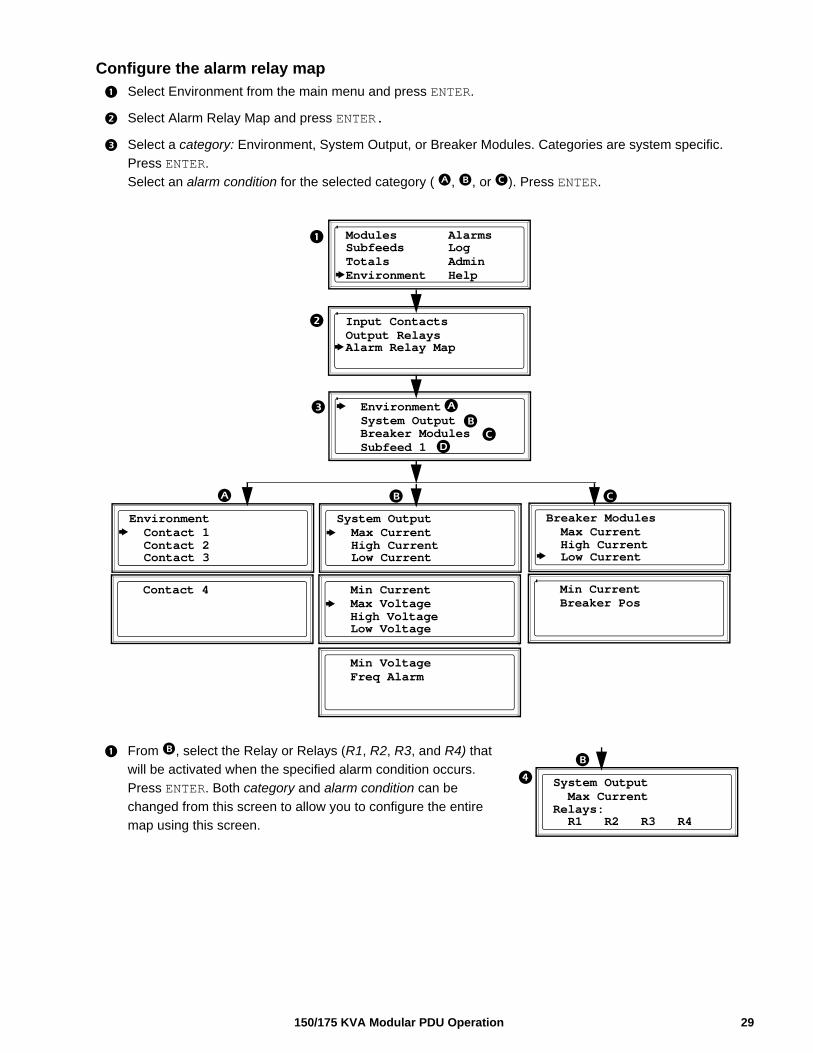
Configure the alarm relay map
Select Environment from the main menu and press ENTER.
Select Alarm Relay Map and press ENTER.
Select a category: Environment, System Output, or Breaker Modules. Categories are system specific.
Press ENTER.
Select an alarm condition for the selected category ( , , or ). Press ENTER.
From , select the Relay or Relays (R1, R2, R3, and R4) that
will be activated when the specified alarm condition occurs.
Press ENTER. Both category and alarm condition can be
changed from this screen to allow you to configure the entire
map using this screen.
Environment System Output
Modules Alarms Subfeeds Log
Environment HelpTotals Admin
Input ContactsOutput RelaysAlarm Relay Map
Breaker Modules
Environment
Contact 3
Contact 1 Contact 2
System Output
Low Current
Max Current High Current
Breaker Modules
Low Current
Max Current High Current
Contact 4
Min Current
Low Voltage
Max Voltage High Voltage
Min Current
Breaker Pos
Min Voltage
Freq Alarm
Subfeed 1
System Output
R1 R2 R3 R4
Max CurrentRelays:
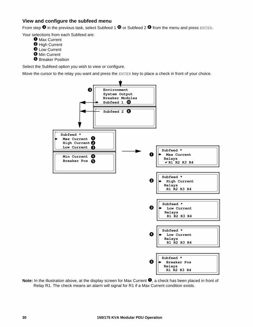
View and configure the subfeed menuFrom step in the previous task, select Subfeed 1 or Subfeed 2 from the menu and press ENTER.
Your selections from each Subfeed are: Max Current High Current Low Current Min Current Breaker Position
Select the Subfeed option you wish to view or configure.
Move the cursor to the relay you want and press the ENTER key to place a check in front of your choice.
Note: In the illustration above, at the display screen for Max Current , a check has been placed in front of Relay R1. The check means an alarm will signal for R1 if a Max Current condition exists.
Environment System Output Breaker Modules
Subfeed *
R1 R2 R3 R4
Max Current Relays
Subfeed *
R1 R2 R3 R4
High Current Relays
Subfeed *
R1 R2 R3 R4
Low Current Relays
Subfeed *
R1 R2 R3 R4
Low Current Relays
Subfeed *
R1 R2 R3 R4
Breaker Pos Relays
Subfeed 1
Subfeed 2
Subfeed * Max Current High Current Low Current
Min Current Breaker Pos
150/175 KVA Modular PDU Operation30
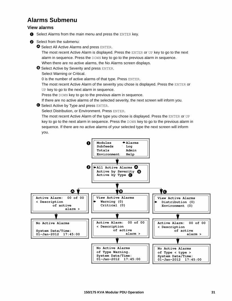
Alarms SubmenuView alarms
Select Alarms from the main menu and press the ENTER key.
Select from the submenu:
Select All Active Alarms and press ENTER.
The most recent Active Alarm is displayed. Press the ENTER or UP key to go to the next
alarm in sequence. Press the DOWN key to go to the previous alarm in sequence.
When there are no active alarms, the No Alarms screen displays.
Select Active by Severity and press ENTER.
Select Warning or Critical.
0 is the number of active alarms of that type. Press ENTER.
The most recent Active Alarm of the severity you chose is displayed. Press the ENTER or
UP key to go to the next alarm in sequence.
Press the DOWN key to go to the previous alarm in sequence.
If there are no active alarms of the selected severity, the next screen will inform you.
Select Active by Type and press ENTER.
Select Distribution, or Environment. Press ENTER.
The most recent Active Alarm of the type you chose is displayed. Press the ENTER or UP
key to go to the next alarm in sequence. Press the DOWN key to go to the previous alarm in
sequence. If there are no active alarms of your selected type the next screen will inform
you.
View Active Alarms
Distribution (0)
Modules Alarms Subfeeds Log
Environment HelpTotals Admin
All Active AlarmsActive by SeverityActive by Type
Environment (0)
Active Alarm: 00 of 00
alarm >
< Description of active
No Active Alarms
01-Jan-2012 17:45:00
of Type < type >System Date/Time:
View Active Alarms
Warning (0) Critical (0)
Active Alarm: 00 of 00
alarm >
< Description of active
No Active Alarms
01-Jan-2012 17:45:00
of Type Warning.System Date/Time:
Active Alarm: 00 of 00
alarm >
< Description of active
No Active Alarms
01-Jan-2012 17:45:00System Date/Time:
31150/175 KVA Modular PDU Operation

Log SubmenuView or clear log items
Select Log from the main menu and press the ENTER key.
Select from the submenu:
Select View New Logged Items and press ENTER. All events logged since your last
viewing will display. The most recent item is displayed first. Note: All logged items include
a time stamp.
Press the ENTER or UP key to go to the next item in sequence. Press the DOWN key to go to
the previous item in sequence. The No Logged Items screen displays when there are no
new logged items.
Select View Entire Log and press ENTER. All events logged since the log was last cleared
will display. The most recent item is displayed first. Press the ENTER or UP key to go to the
next item in sequence. Press the DOWN key to go to the previous item in sequence. The No
Logged Items screen displays when there are no new logged items.
Select Clear Entire Log and press ENTER. The following screens are typically password
protected. Select YES to clear the log, or NO to cancel the process. Press ENTER. If you
press YES, the next screen confirms that the log has been cleared. Press any key to
continue.
Confirm:
YES, Clear Log
Clear Entire Log
Modules Alarms Subfeeds Log
Environment HelpTotals Admin
New Logged ItemsEntire LogClear Log
Cancel
Log cleared
menu.
Press any key toreturn to previous
Log Item: 0 of 00
dd/mm/yyy hh:mm:ss
< Description of Most Recent Alarm >
No New Logged Items
21-Jan-2012 17:45:00System Date/Time:
Logged Item: 00 of 00
dd/mm/yyy hh:mm:ss
< Description of Most Recent Alarm >
No New Logged Items
21-Jan-2012 17:45:00System Date/Time:
150/175 KVA Modular PDU Operation32
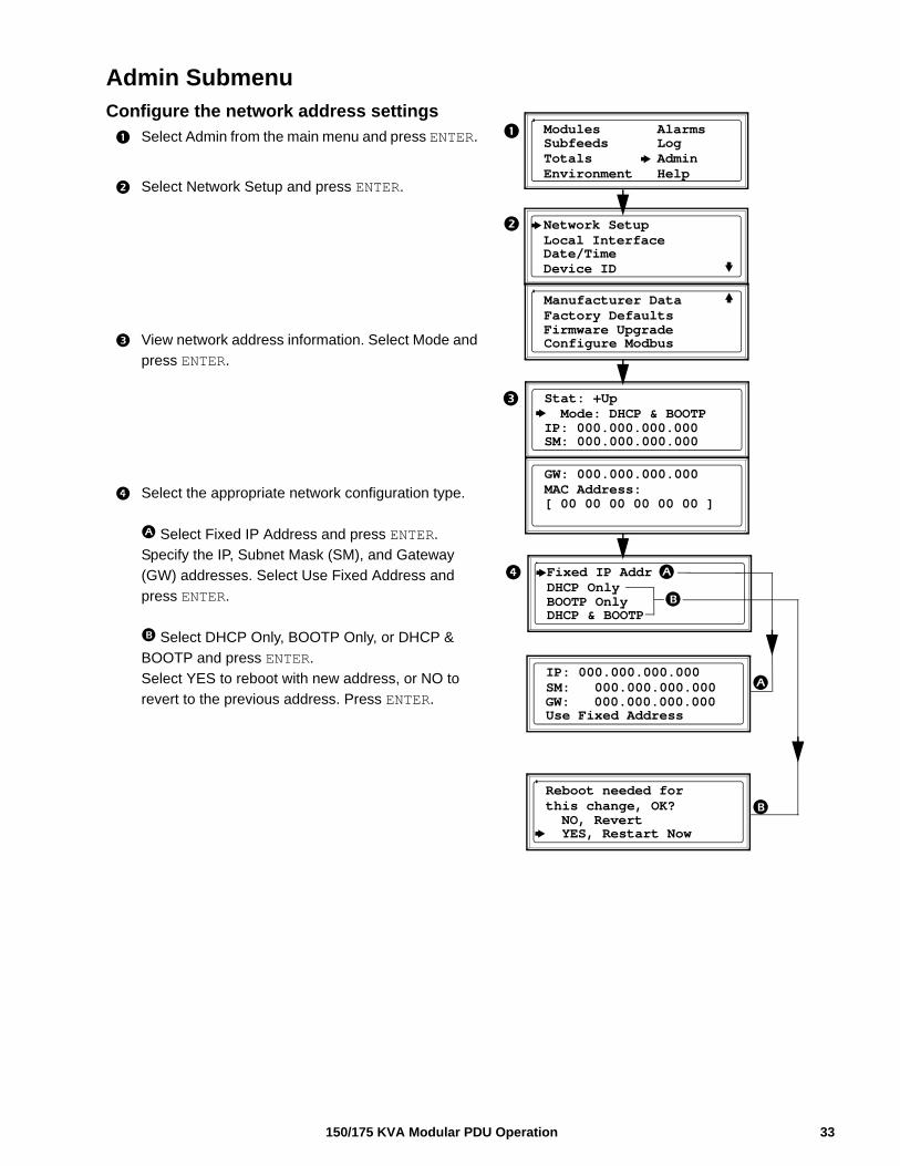
Admin SubmenuConfigure the network address settings
Select Admin from the main menu and press ENTER.
Select Network Setup and press ENTER.
View network address information. Select Mode and
press ENTER.
Select the appropriate network configuration type.
Select Fixed IP Address and press ENTER.
Specify the IP, Subnet Mask (SM), and Gateway
(GW) addresses. Select Use Fixed Address and
press ENTER.
Select DHCP Only, BOOTP Only, or DHCP &
BOOTP and press ENTER.
Select YES to reboot with new address, or NO to
revert to the previous address. Press ENTER.
Manufacturer Data
Configure Modbus
Factory Defaults
Modules Alarms Subfeeds Log
Environment HelpTotals Admin
Network SetupLocal InterfaceDate/TimeDevice ID
Firmware Upgrade
Stat: +Up
SM: 000.000.000.000
Mode: DHCP & BOOTPIP: 000.000.000.000
GW: 000.000.000.000
MAC Address:[ 00 00 00 00 00 00 ]
Fixed IP Addr
DHCP & BOOTP
DHCP OnlyBOOTP Only
IP: 000.000.000.000
Use Fixed Address
SM: 000.000.000.000GW: 000.000.000.000
Reboot needed for
YES, Restart Now
this change, OK? NO, Revert
33150/175 KVA Modular PDU Operation
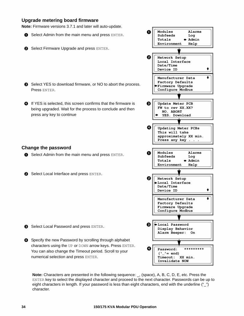
Upgrade metering board firmwareNote: Firmware versions 3.7.1 and later will auto-update.
Select Admin from the main menu and press ENTER.
Select Firmware Upgrade and press ENTER.
Select YES to download firmware, or NO to abort the process.
Press ENTER.
If YES is selected, this screen confirms that the firmware is
being upgraded. Wait for the process to conclude and then
press any key to continue
Change the password
Select Admin from the main menu and press ENTER.
Select Local Interface and press ENTER.
Select Local Password and press ENTER.
Specify the new Password by scrolling through alphabet
characters using the UP or DOWN arrow keys. Press ENTER.
You can also change the Timeout period. Scroll to your
numerical selection and press ENTER.
Note: Characters are presented in the following sequence: _, (space), A, B, C, D, E, etc. Press the ENTER key to select the displayed character and proceed to the next character. Passwords can be up to eight characters in length. If your password is less than eight characters, end with the underline (“_”) character.
Manufacturer Data
Configure Modbus
Factory Defaults
Modules Alarms Subfeeds Log
Environment HelpTotals Admin
Network SetupLocal InterfaceDate/TimeDevice ID
Firmware Upgrade
Update Meter PCB
YES. Download
FW to rev XX.XX? NO. ABORT
Updating Meter PCBs
Press any key . . .
This will takeapproximately XX min.
Manufacturer Data
Configure Modbus
Factory Defaults
Modules Alarms Subfeeds Log
Environment HelpTotals Admin
Network SetupLocal InterfaceDate/TimeDevice ID
Firmware Upgrade
Local PasswordDisplay BehaviorAlarm Beeper: On
Password: *********
Invalidate NOW
(‘_’= end)Timeout: XX min.
150/175 KVA Modular PDU Operation34
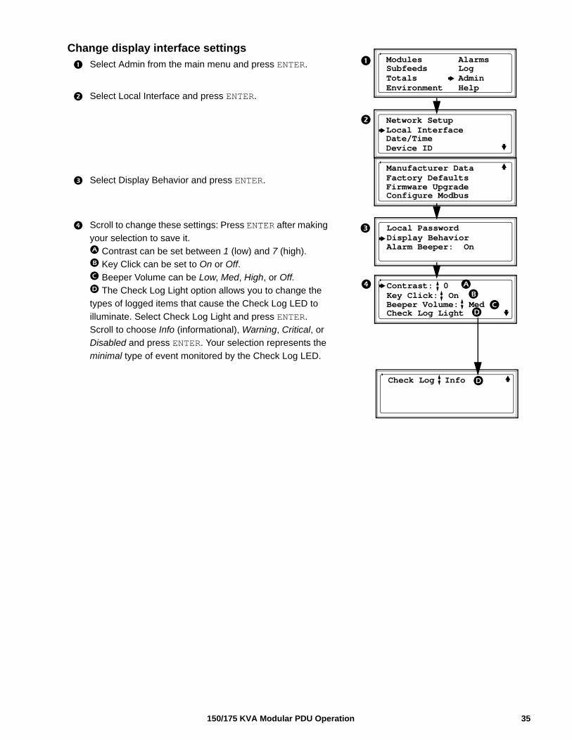
Change display interface settings
Select Admin from the main menu and press ENTER.
Select Local Interface and press ENTER.
Select Display Behavior and press ENTER.
Scroll to change these settings: Press ENTER after making
your selection to save it.
Contrast can be set between 1 (low) and 7 (high).
Key Click can be set to On or Off.
Beeper Volume can be Low, Med, High, or Off.
The Check Log Light option allows you to change the
types of logged items that cause the Check Log LED to
illuminate. Select Check Log Light and press ENTER.
Scroll to choose Info (informational), Warning, Critical, or
Disabled and press ENTER. Your selection represents the
minimal type of event monitored by the Check Log LED.
Manufacturer Data
Configure Modbus
Factory Defaults
Modules Alarms Subfeeds Log
Environment HelpTotals Admin
Network SetupLocal InterfaceDate/TimeDevice ID
Firmware Upgrade
Local PasswordDisplay BehaviorAlarm Beeper: On
Contrast: 0
Check Log Light
Key Click: OnBeeper Volume: Med
Check Log Info
35150/175 KVA Modular PDU Operation
150/175 KVA Modular PDU Operation36
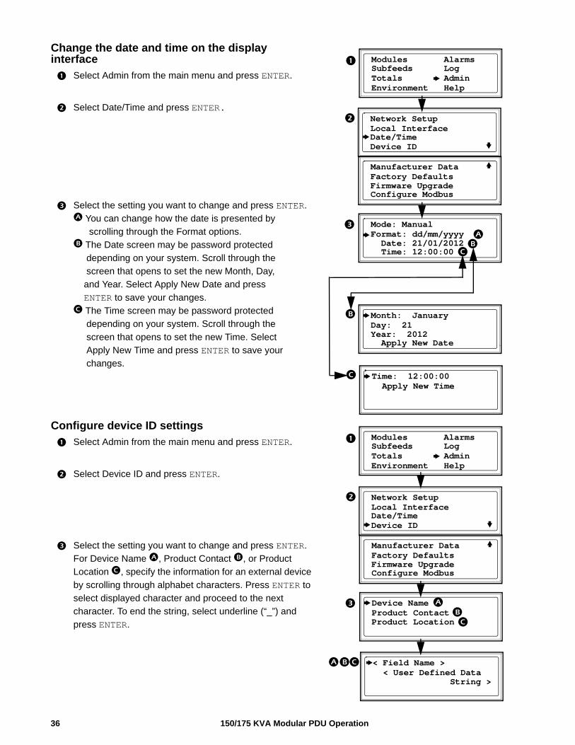
Change the date and time on the display interface
Select Admin from the main menu and press ENTER.
Select Date/Time and press ENTER.
Select the setting you want to change and press ENTER.
You can change how the date is presented by
scrolling through the Format options.
The Date screen may be password protected
depending on your system. Scroll through the
screen that opens to set the new Month, Day,
and Year. Select Apply New Date and press
ENTER to save your changes.
The Time screen may be password protected
depending on your system. Scroll through the
screen that opens to set the new Time. Select
Apply New Time and press ENTER to save your
changes.
Configure device ID settings
Select Admin from the main menu and press ENTER.
Select Device ID and press ENTER.
Select the setting you want to change and press ENTER.
For Device Name , Product Contact , or Product
Location , specify the information for an external device
by scrolling through alphabet characters. Press ENTER to
select displayed character and proceed to the next
character. To end the string, select underline (“_”) and
press ENTER.
Manufacturer Data
Configure Modbus
Factory Defaults
Modules Alarms Subfeeds Log
Environment HelpTotals Admin
Network SetupLocal InterfaceDate/TimeDevice ID
Firmware Upgrade
Mode: Manual
Time: 12:00:00
Format: dd/mm/yyyy Date: 21/01/2012
Month: January
Apply New Date
Day: 21Year: 2012
Time: 12:00:00 Apply New Time
Manufacturer Data
Configure Modbus
Factory Defaults
Modules Alarms Subfeeds Log
Environment HelpTotals Admin
Network SetupLocal InterfaceDate/TimeDevice ID
Firmware Upgrade
Device Name
Product ContactProduct Location
< Field Name >
< User Defined Data String >
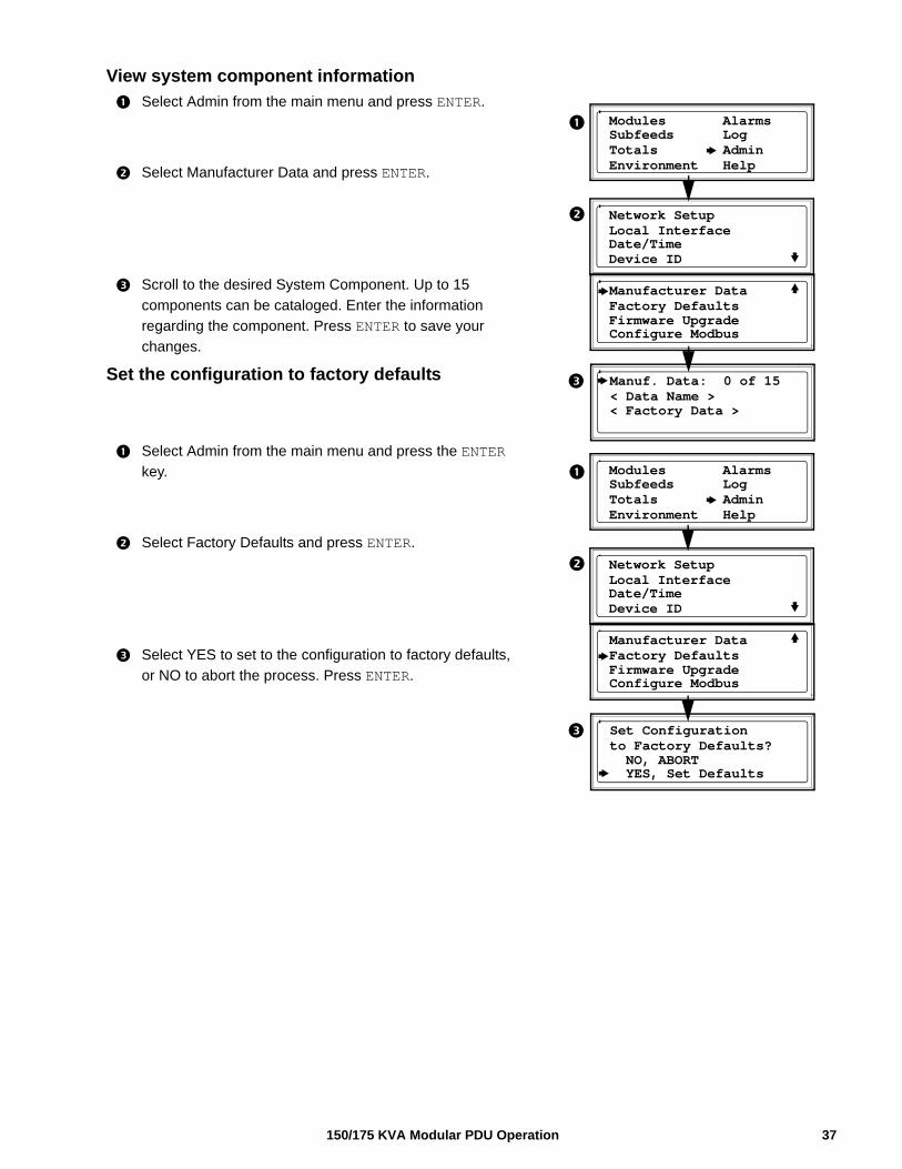
View system component information
Select Admin from the main menu and press ENTER.
Select Manufacturer Data and press ENTER.
Scroll to the desired System Component. Up to 15
components can be cataloged. Enter the information
regarding the component. Press ENTER to save your
changes.
Set the configuration to factory defaults
Select Admin from the main menu and press the ENTER
key.
Select Factory Defaults and press ENTER.
Select YES to set to the configuration to factory defaults,
or NO to abort the process. Press ENTER.
Manufacturer Data
Configure Modbus
Factory Defaults
Modules Alarms Subfeeds Log
Environment HelpTotals Admin
Network SetupLocal InterfaceDate/TimeDevice ID
Firmware Upgrade
Manuf. Data: 0 of 15
< Data Name >< Factory Data >
Manufacturer Data
Configure Modbus
Factory Defaults
Modules Alarms Subfeeds Log
Environment HelpTotals Admin
Network SetupLocal InterfaceDate/TimeDevice ID
Firmware Upgrade
Set Configuration
YES, Set Defaults
to Factory Defaults? NO, ABORT
37150/175 KVA Modular PDU Operation
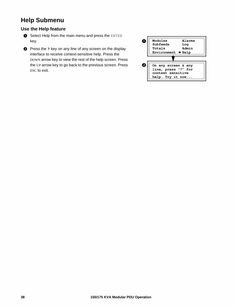
Help SubmenuUse the Help feature
Select Help from the main menu and press the ENTER
key.
Press the ? key on any line of any screen on the display
interface to receive context-sensitive help. Press the
DOWN arrow key to view the rest of the help screen. Press
the UP arrow key to go back to the previous screen. Press
ESC to exit.
Modules Alarms Subfeeds Log
Environment HelpTotals Admin
On any screen & anyline, press ‘?’ for context sensitive help. Try it now...
150/175 KVA Modular PDU Operation38
Modbus Configuration
Configure Modbus through the Display InterfaceModbus configuration
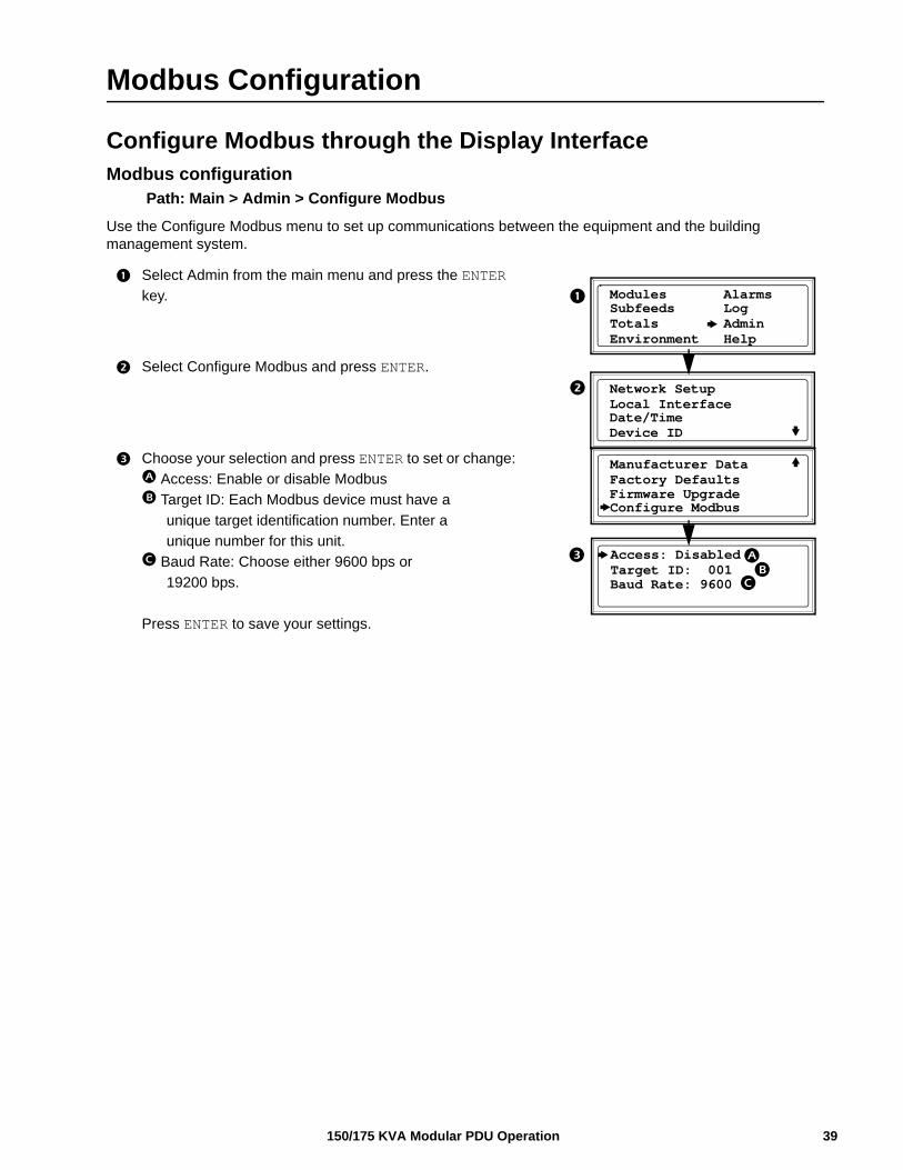
Path: Main > Admin > Configure Modbus
Use the Configure Modbus menu to set up communications between the equipment and the building management system.
Select Admin from the main menu and press the ENTER
key.
Select Configure Modbus and press ENTER.
Choose your selection and press ENTER to set or change:
Access: Enable or disable Modbus
Target ID: Each Modbus device must have a
unique target identification number. Enter a
unique number for this unit.
Baud Rate: Choose either 9600 bps or
19200 bps.
Press ENTER to save your settings.
Manufacturer Data
Configure Modbus
Factory Defaults
Modules Alarms Subfeeds Log
Environment HelpTotals Admin
Network SetupLocal InterfaceDate/TimeDevice ID
Firmware Upgrade
Access: Disabled
Target ID: 001Baud Rate: 9600
39150/175 KVA Modular PDU Operation
Modbus cable connection
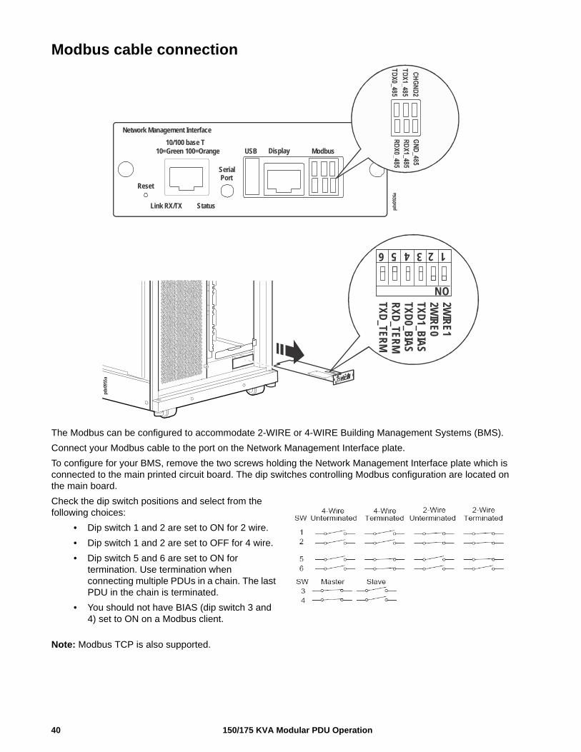
The Modbus can be configured to accommodate 2-WIRE or 4-WIRE Building Management Systems (BMS).
Connect your Modbus cable to the port on the Network Management Interface plate.
To configure for your BMS, remove the two screws holding the Network Management Interface plate which is connected to the main printed circuit board. The dip switches controlling Modbus configuration are located on the main board.
Check the dip switch positions and select from the following choices:
• Dip switch 1 and 2 are set to ON for 2 wire.
• Dip switch 1 and 2 are set to OFF for 4 wire.
• Dip switch 5 and 6 are set to ON for termination. Use termination when connecting multiple PDUs in a chain. The last PDU in the chain is terminated.
• You should not have BIAS (dip switch 3 and 4) set to ON on a Modbus client.
Note: Modbus TCP is also supported.
pdx0
955a
123456
ON
2WIR
E12W
IRE0
TXD1_B
IAS
TXD0_B
IAS
RXD
_TERM
TXD_TER
M
Network Management Interface
10/100 base T10=Green 100=Orange
Reset
Serial Port
USB Display Modbus
Link RX/TX Status pdx0
926a
150/175 KVA Modular PDU Operation40
Network Management Configuration
Overview Note: For complete Network Management Card setup instructions, see the online User Guide at www.apc.com.
Initial setupYou must configure the following three TCP/IP settings before the Modular PDU can operate on a network:
• IP address of the Modular PDU
• Subnet mask
• Default gatewayIf a default gateway is unavailable, use the IP address of a computer (that is usually running) located on the same subnet as the NMC. The NMC uses the default gateway to test the network when traffic is light.
Note: Do not use the loopback address as the default gateway address for the Network Management Card. You will lose communication with the equipment. Doing so will disable the card and require you to reset TCP/IP settings to their defaults using a local serial login.
TCP/IP configuration methods. Use one of the following methods to define the basic TCP/IP settings needed by the Network Management Card.
• Device IP Configuration Wizard
• BOOTP or DHCP server
• Networked computer
Device IP Configuration WizardThe Wizard runs on Microsoft Windows 2000, Windows 2003, and Windows XP operating systems. The Device IP Configuration Wizard configures the IP address, subnet mask, and default gateway of one or more NMCs. You can use the Wizard in either of the following ways:
• Remotely over your TCP/IP network to discover and configure unconfigured NMCs on the same network segment as the computer running the Wizard.
• Through a direct connection from a serial port of your computer to the PDU to configureor reconfigure it.
Installation. Install the Wizard from a downloaded executable file:
1. Go to www.apc.com
2. Download the Device IP Configuration Wizard.
3. Run the executable file in the folder in which it was downloaded.
Launch the Wizard. The installation creates a shortcut link in the Start menu to launch the Wizard. Most software firewalls must be temporarily disabled for the Wizard to discover unconfigured NMCs.
41150/175 KVA Modular PDU Operation
Supported Web browsersUse Microsoft® Internet Explorer (IE) 7.x and higher (Windows operating systems) or Mozilla Firefox 3.0.6 or higher (all operating systems) to access the NMC through its Web interface. Other commonly available browsers may work but have not been fully tested by Schneider Electric. The NMC cannot work with a proxy server. Before using a Web browser to access its Web interface, do one of the following:
• Configure the Web browser to disable the use of a proxy server for the NMC.
• Configure the proxy server so that it does not proxy the specific IP address of the NMC.
Network management featuresThese applications and utilities work with a Modular PDU that connects to the network through its Network Management Card:
• StruxureWare —Provide enterprise-level power management and management of Schneider Electric agents, Modular PDUs, information controllers, and environmental monitors
• PowerNet® Management Information Base (MIB) with a standard MIB browser—Perform SNMP SETs and GETs and to use SNMP traps
• APC Device IP Configuration Wizard—Configure the basic settings of one or more NMCs over the network
• APC Security Wizard—Create the components needed for high security for the NMC when using Secure Sockets Layer (SSL) and related protocols and encryption routines
150/175 KVA Modular PDU Operation42
Log OnUse the DNS name or System IP address of the NMC for the URL address of the Web interface. The default password is apc for all three account types. The default user name differs by account type:
• apc for an Administrator
• device for a Device user
• readonly for a Read-Only user
If you are using HTTPS (SSL/TSL) as your access protocol, your logon credentials are compared with information in a server certificate. If the certificate was created with the APC Security Wizard, and an IP address was specified as the common name in the certificate, you must use an IP address to log on to the NMC. If a DNS name was specified as the common name on the certificate, you must use a DNS name to log on.
URL address formatsType the DNS name or IP address of the NMC in the URL address field of the Web browser and press ENTER. When you specify a non-default Web server port in Internet Explorer, you must include http:// or https:// in the URL.
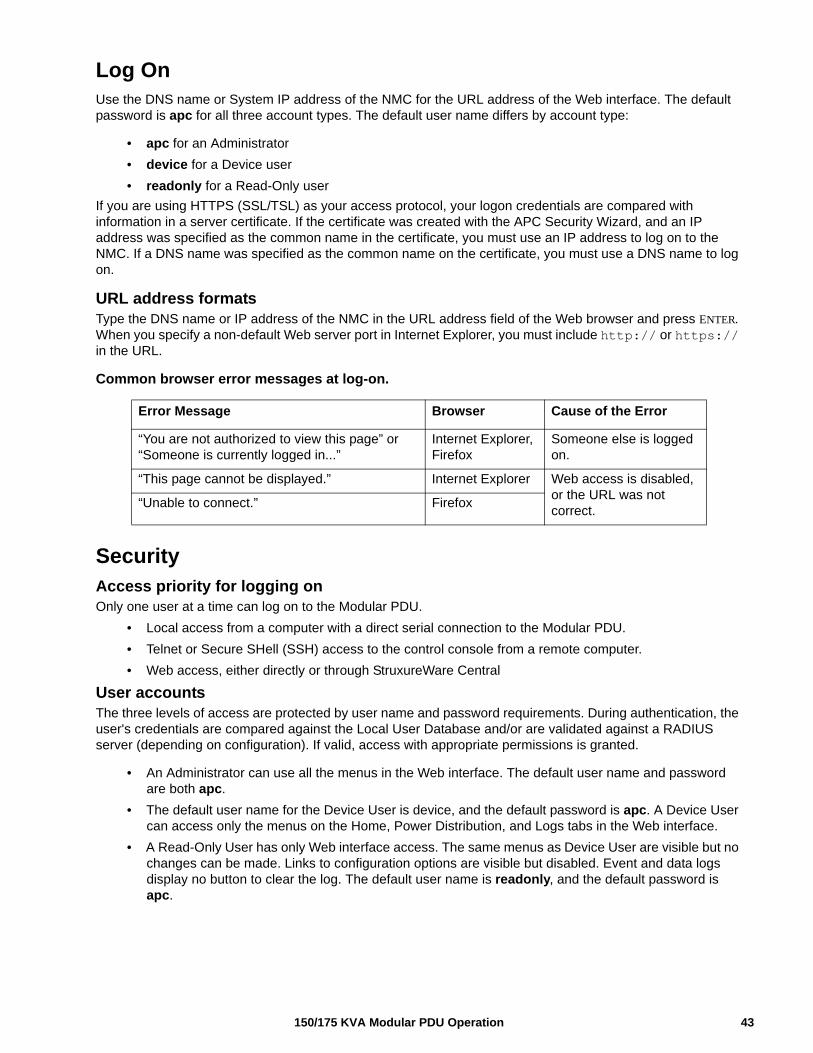
Common browser error messages at log-on.
SecurityAccess priority for logging onOnly one user at a time can log on to the Modular PDU.
• Local access from a computer with a direct serial connection to the Modular PDU.
• Telnet or Secure SHell (SSH) access to the control console from a remote computer.
• Web access, either directly or through StruxureWare Central
User accountsThe three levels of access are protected by user name and password requirements. During authentication, the user's credentials are compared against the Local User Database and/or are validated against a RADIUS server (depending on configuration). If valid, access with appropriate permissions is granted.
• An Administrator can use all the menus in the Web interface. The default user name and password are both apc.
• The default user name for the Device User is device, and the default password is apc. A Device User can access only the menus on the Home, Power Distribution, and Logs tabs in the Web interface.
• A Read-Only User has only Web interface access. The same menus as Device User are visible but no changes can be made. Links to configuration options are visible but disabled. Event and data logs display no button to clear the log. The default user name is readonly, and the default password is apc.
Error Message Browser Cause of the Error
“You are not authorized to view this page” or “Someone is currently logged in...”
Internet Explorer, Firefox
Someone else is logged on.
“This page cannot be displayed.” Internet Explorer Web access is disabled, or the URL was not correct.
“Unable to connect.” Firefox
43150/175 KVA Modular PDU Operation
Watchdog FeaturesWatchdog mechanisms detect internal problems. After a restart, a System: Warmstart event is recorded in the event log.
Network interface watchdog mechanismWatchdog mechanisms protect the NMC from becoming inaccessible over the network. If it does not receive any network traffic for 9.5 minutes, it assumes there is a problem with its interface and restarts.
Resetting the network timerTo ensure the NMC does not restart if the network is quiet for 9.5 minutes, it attempts to contact the default gateway every 4.5 minutes. The gateway response resets the 9.5-minute timer. If your application does not require or have a gateway, specify the IP address of a computer that is running on the network most of the time and is on the same subnet. The network traffic of that computer will restart the 9.5-minute timer frequently enough to prevent the NMC from restarting.
Recover from a Lost Password 1. At the local computer, select a serial port, and disable any service that uses it.
2. Connect the provided serial cable to the computer and the port on the PDU.
3. Run a terminal program (such as HyperTerminal®) and configure the port for 9600 bps, 8 data bits, no parity, 1 stop bit, and no flow control.
4. Press ENTER, repeatedly if necessary, to display the User Name prompt. If you are unable to display the User Name prompt, verify the following:
– The serial port is not in use by another application.
– The terminal settings are correct as specified in step 3.
– The correct cable is being used.
5. Press the Reset button on the back of the unit. The Status LED will flash. Press the Reset button a second time while the LED is flashing to reset the user name and password to the default.
6. Press ENTER as many times as necessary until the User Name prompt displays, then use the default, apc, user name and password. (If you take longer than 30 seconds to log on after the User Name prompt is displayed, you must repeat step 5 and log on again.)
7. Select System, then User Manager.
8. Select Administrator, and change the User Name and Password settings from the default apc.
9. Press CTRL+C and log off. Return the local computer to its configuration.
150/175 KVA Modular PDU Operation44
Maintenance
Parts ReplacementDetermine if you need a replacement part
To determine if you need a replacement part, contact Schneider Electric Customer Support and follow the procedure below so that a representative can assist you promptly:
1. The display interface may show additional screens if module replacement is necessary. Press any key to scroll through these lists, record the information, and provide it to the representative.
2. Write down the serial number of the unit so that you will have it easily accessible when you contact Customer Support.
3. If possible, call Customer Support from a telephone that is within reach of the unit so that you can gather and report additional information to the representative.
4. Be prepared to provide a detailed description of the problem. A representative will attempt to help you over the telephone, if possible, or will assign a Return Material Authorization (RMA) number to you. If a module is returned, this RMA number must be clearly printed on the outside of the package.
5. If the unit is within the warranty period, repairs or replacements will be performed free of charge. If it is not within the warranty period, there will be a charge.
6. If the unit is covered by a service contract, have the contract available to provide information to the representative.
Return partsContact Customer Support to obtain an (Returned Materials Authorization (RMA) number.
To return a module, pack the module in the original shipping materials, and return it by insured, prepaid carrier. The Customer Support representative will provide the destination address. If you no longer have the original shipping materials, ask the representative about obtaining a new set. Pack the module properly to avoid damage in transit. Never use Styrofoam beads or other loose packaging materials when shipping a module, as the module may settle in transit and become damaged. Enclose a letter in the package with your name, RMA number, address, a copy of the sales receipt, description of the problem, a phone number, and a check as payment (if necessary).
Note: Damages sustained in transit are not covered under warranty.
45150/175 KVA Modular PDU Operation
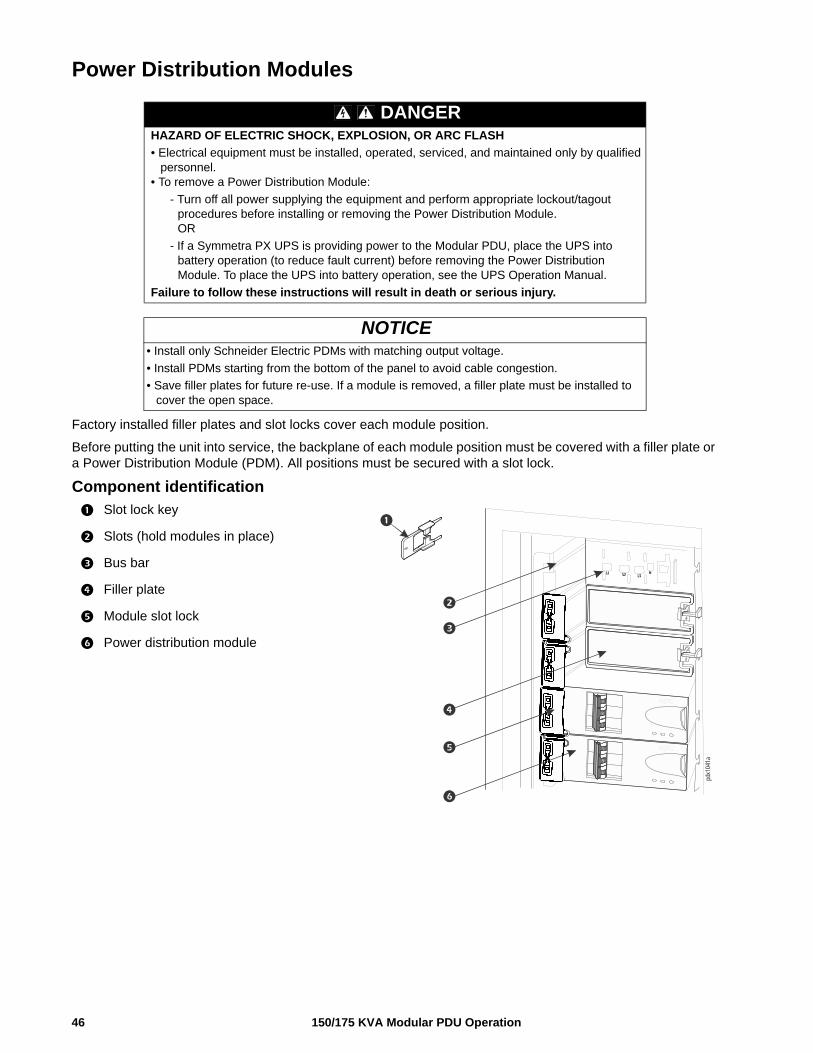
Power Distribution Modules
Factory installed filler plates and slot locks cover each module position.
Before putting the unit into service, the backplane of each module position must be covered with a filler plate or a Power Distribution Module (PDM). All positions must be secured with a slot lock.
Component identification
Slot lock key
Slots (hold modules in place)
Bus bar
Filler plate
Module slot lock
Power distribution module
DANGERHAZARD OF ELECTRIC SHOCK, EXPLOSION, OR ARC FLASH
• Electrical equipment must be installed, operated, serviced, and maintained only by qualified personnel.
• To remove a Power Distribution Module:
- Turn off all power supplying the equipment and perform appropriate lockout/tagout procedures before installing or removing the Power Distribution Module.OR
- If a Symmetra PX UPS is providing power to the Modular PDU, place the UPS into battery operation (to reduce fault current) before removing the Power Distribution Module. To place the UPS into battery operation, see the UPS Operation Manual.
Failure to follow these instructions will result in death or serious injury.
NOTICE• Install only Schneider Electric PDMs with matching output voltage.
• Install PDMs starting from the bottom of the panel to avoid cable congestion.
• Save filler plates for future re-use. If a module is removed, a filler plate must be installed to cover the open space.
pdx1
041a
150/175 KVA Modular PDU Operation46
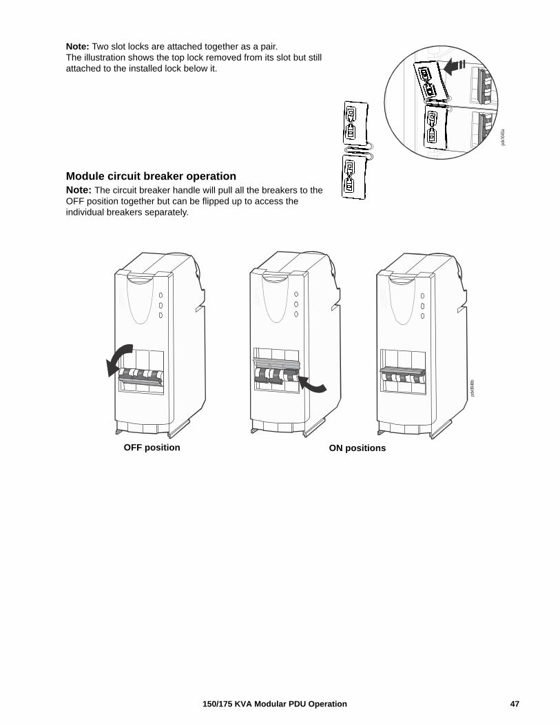
Note: Two slot locks are attached together as a pair. The illustration shows the top lock removed from its slot but still attached to the installed lock below it.
Module circuit breaker operationNote: The circuit breaker handle will pull all the breakers to the OFF position together but can be flipped up to access the individual breakers separately.
pdx1
043a
pdx0
848b
OFF position ON positions
47150/175 KVA Modular PDU Operation
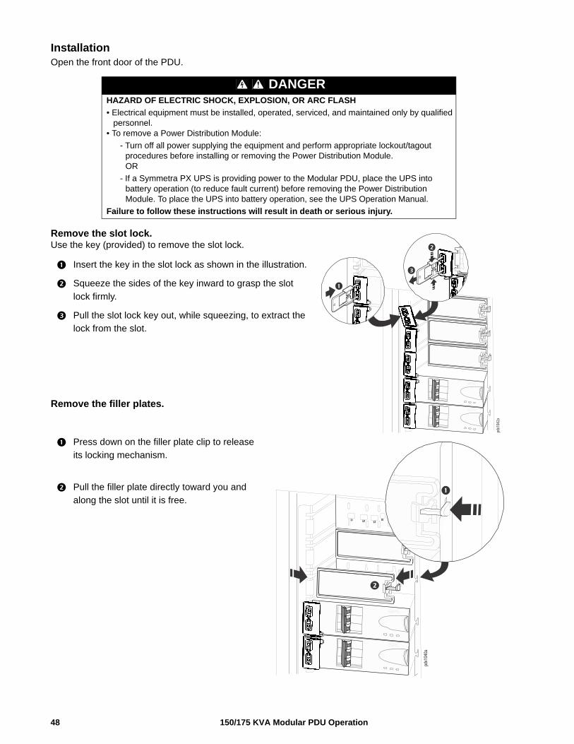
150/175 KVA Modular PDU Operation48
Installation Open the front door of the PDU.
Remove the slot lock. Use the key (provided) to remove the slot lock.
Insert the key in the slot lock as shown in the illustration.
Squeeze the sides of the key inward to grasp the slot
lock firmly.
Pull the slot lock key out, while squeezing, to extract the
lock from the slot.
Remove the filler plates.
Press down on the filler plate clip to release
its locking mechanism.
Pull the filler plate directly toward you and
along the slot until it is free.
DANGERHAZARD OF ELECTRIC SHOCK, EXPLOSION, OR ARC FLASH
• Electrical equipment must be installed, operated, serviced, and maintained only by qualified personnel.
• To remove a Power Distribution Module:
- Turn off all power supplying the equipment and perform appropriate lockout/tagout procedures before installing or removing the Power Distribution Module.OR
- If a Symmetra PX UPS is providing power to the Modular PDU, place the UPS into battery operation (to reduce fault current) before removing the Power Distribution Module. To place the UPS into battery operation, see the UPS Operation Manual.
Failure to follow these instructions will result in death or serious injury.
pdx1
042a
pdx1
040a
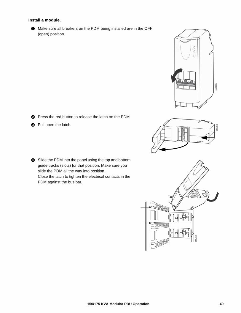
Install a module.
Make sure all breakers on the PDM being installed are in the OFF
(open) position.
Press the red button to release the latch on the PDM.
Pull open the latch.
Slide the PDM into the panel using the top and bottom
guide tracks (slots) for that position. Make sure you
slide the PDM all the way into position.\
Close the latch to tighten the electrical contacts in the
PDM against the bus bar.
pdx0
257b
pdx0
298b
49150/175 KVA Modular PDU Operation
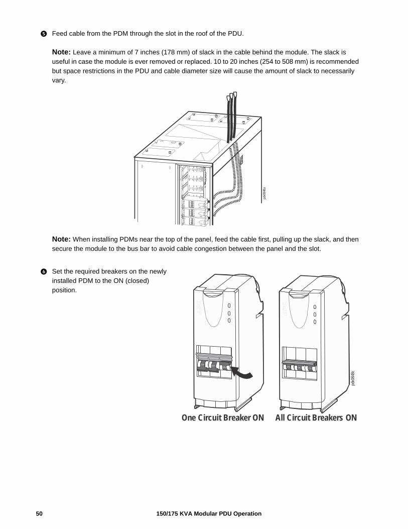
Feed cable from the PDM through the slot in the roof of the PDU.
Note: Leave a minimum of 7 inches (178 mm) of slack in the cable behind the module. The slack is
useful in case the module is ever removed or replaced. 10 to 20 inches (254 to 508 mm) is recommended
but space restrictions in the PDU and cable diameter size will cause the amount of slack to necessarily
vary.
Note: When installing PDMs near the top of the panel, feed the cable first, pulling up the slack, and then
secure the module to the bus bar to avoid cable congestion between the panel and the slot.
Set the required breakers on the newly
installed PDM to the ON (closed)
position.
pdx0
840a
pdx0
848c
One Circuit Breaker ON All Circuit Breakers ON
150/175 KVA Modular PDU Operation50
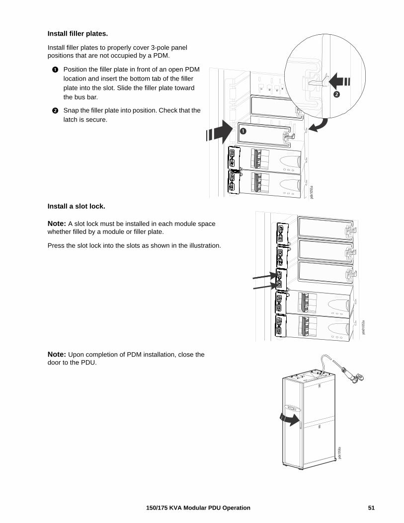
Install filler plates.
Install filler plates to properly cover 3-pole panel positions that are not occupied by a PDM.
Position the filler plate in front of an open PDM
location and insert the bottom tab of the filler
plate into the slot. Slide the filler plate toward
the bus bar.
Snap the filler plate into position. Check that the
latch is secure.
Install a slot lock.
Note: A slot lock must be installed in each module space whether filled by a module or filler plate.
Press the slot lock into the slots as shown in the illustration.
Note: Upon completion of PDM installation, close the door to the PDU.
pdx1
055a
pdx0
\105
3a
pdx1
058a
51150/175 KVA Modular PDU Operation
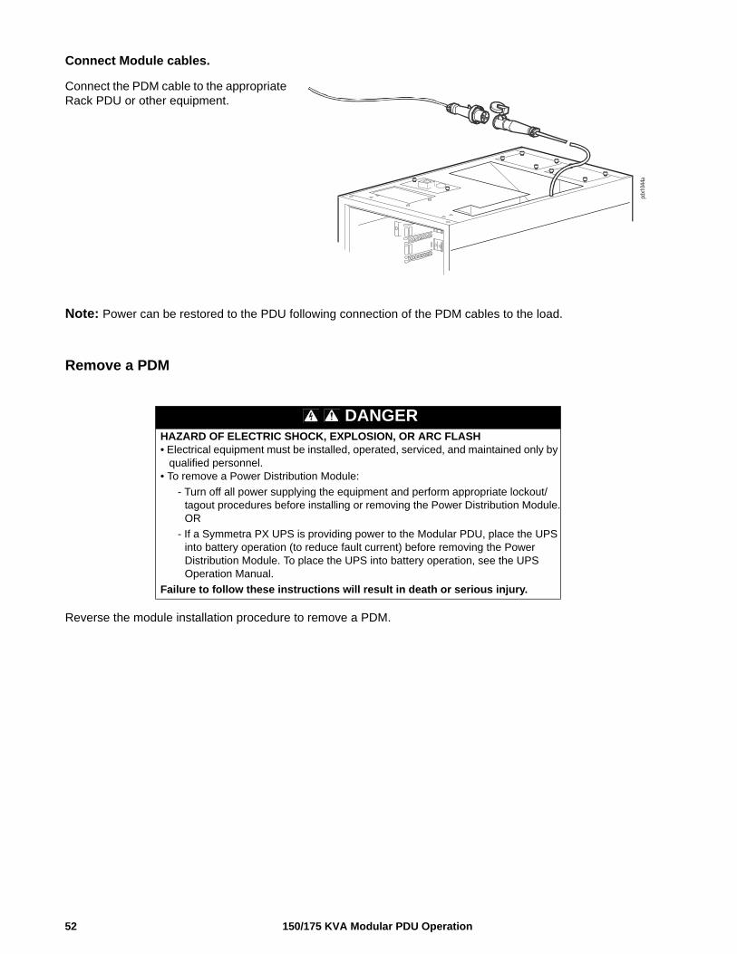
Connect Module cables.
Connect the PDM cable to the appropriate Rack PDU or other equipment.
Note: Power can be restored to the PDU following connection of the PDM cables to the load.
Remove a PDM
Reverse the module installation procedure to remove a PDM.
DANGERHAZARD OF ELECTRIC SHOCK, EXPLOSION, OR ARC FLASH• Electrical equipment must be installed, operated, serviced, and maintained only by
qualified personnel.• To remove a Power Distribution Module:
- Turn off all power supplying the equipment and perform appropriate lockout/tagout procedures before installing or removing the Power Distribution Module.OR
- If a Symmetra PX UPS is providing power to the Modular PDU, place the UPS into battery operation (to reduce fault current) before removing the Power Distribution Module. To place the UPS into battery operation, see the UPS Operation Manual.
Failure to follow these instructions will result in death or serious injury.
pdx1
044a
150/175 KVA Modular PDU Operation52
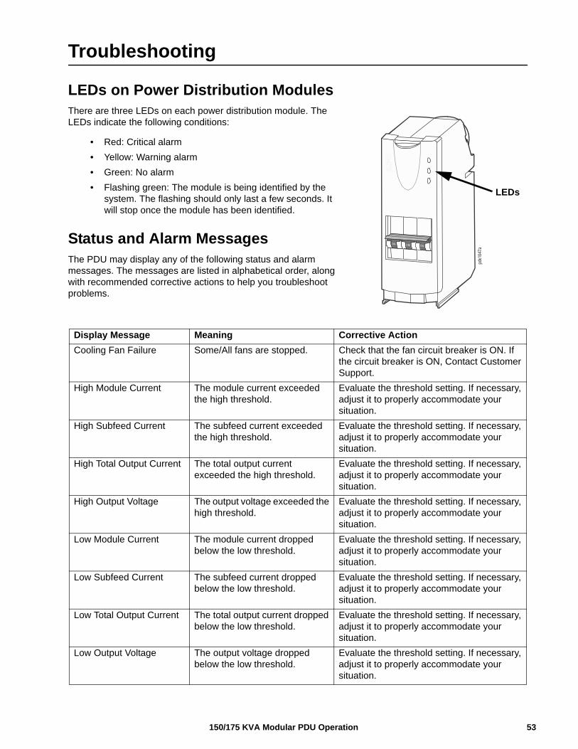
Troubleshooting
LEDs on Power Distribution ModulesThere are three LEDs on each power distribution module. The LEDs indicate the following conditions:
• Red: Critical alarm
• Yellow: Warning alarm
• Green: No alarm
• Flashing green: The module is being identified by the system. The flashing should only last a few seconds. It will stop once the module has been identified.
Status and Alarm MessagesThe PDU may display any of the following status and alarm messages. The messages are listed in alphabetical order, along with recommended corrective actions to help you troubleshoot problems.
Display Message Meaning Corrective Action
Cooling Fan Failure Some/All fans are stopped. Check that the fan circuit breaker is ON. If the circuit breaker is ON, Contact Customer Support.
High Module Current The module current exceeded the high threshold.
Evaluate the threshold setting. If necessary, adjust it to properly accommodate your situation.
High Subfeed Current The subfeed current exceeded the high threshold.
Evaluate the threshold setting. If necessary, adjust it to properly accommodate your situation.
High Total Output Current The total output current exceeded the high threshold.
Evaluate the threshold setting. If necessary, adjust it to properly accommodate your situation.
High Output Voltage The output voltage exceeded the high threshold.
Evaluate the threshold setting. If necessary, adjust it to properly accommodate your situation.
Low Module Current The module current dropped below the low threshold.
Evaluate the threshold setting. If necessary, adjust it to properly accommodate your situation.
Low Subfeed Current The subfeed current dropped below the low threshold.
Evaluate the threshold setting. If necessary, adjust it to properly accommodate your situation.
Low Total Output Current The total output current dropped below the low threshold.
Evaluate the threshold setting. If necessary, adjust it to properly accommodate your situation.
Low Output Voltage The output voltage dropped below the low threshold.
Evaluate the threshold setting. If necessary, adjust it to properly accommodate your situation.
pdx1
047a
LEDs
53150/175 KVA Modular PDU Operation
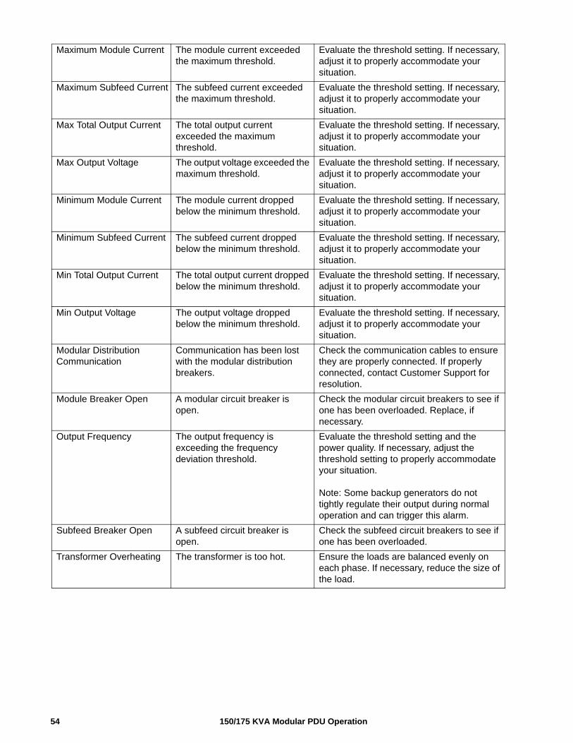
Maximum Module Current The module current exceeded the maximum threshold.
Evaluate the threshold setting. If necessary, adjust it to properly accommodate your situation.
Maximum Subfeed Current The subfeed current exceeded the maximum threshold.
Evaluate the threshold setting. If necessary, adjust it to properly accommodate your situation.
Max Total Output Current The total output current exceeded the maximum threshold.
Evaluate the threshold setting. If necessary, adjust it to properly accommodate your situation.
Max Output Voltage The output voltage exceeded the maximum threshold.
Evaluate the threshold setting. If necessary, adjust it to properly accommodate your situation.
Minimum Module Current The module current dropped below the minimum threshold.
Evaluate the threshold setting. If necessary, adjust it to properly accommodate your situation.
Minimum Subfeed Current The subfeed current dropped below the minimum threshold.
Evaluate the threshold setting. If necessary, adjust it to properly accommodate your situation.
Min Total Output Current The total output current dropped below the minimum threshold.
Evaluate the threshold setting. If necessary, adjust it to properly accommodate your situation.
Min Output Voltage The output voltage dropped below the minimum threshold.
Evaluate the threshold setting. If necessary, adjust it to properly accommodate your situation.
Modular Distribution Communication
Communication has been lost with the modular distribution breakers.
Check the communication cables to ensure they are properly connected. If properly connected, contact Customer Support for resolution.
Module Breaker Open A modular circuit breaker is open.
Check the modular circuit breakers to see if one has been overloaded. Replace, if necessary.
Output Frequency The output frequency is exceeding the frequency deviation threshold.
Evaluate the threshold setting and the power quality. If necessary, adjust the threshold setting to properly accommodate your situation.
Note: Some backup generators do not tightly regulate their output during normal operation and can trigger this alarm.
Subfeed Breaker Open A subfeed circuit breaker is open.
Check the subfeed circuit breakers to see if one has been overloaded.
Transformer Overheating The transformer is too hot. Ensure the loads are balanced evenly on each phase. If necessary, reduce the size of the load.
150/175 KVA Modular PDU Operation54
Radio Frequency InterferenceNote: Changes or modifications to this unit not expressly approved by the party responsible for compliance could void the user’s authority to operate this equipment.
USA—FCC
This equipment has been tested and found to comply with the limits for a Class A digital device, pursuant to part 15 of the FCC Rules. These limits are designed to provide reasonable protection against harmful interference when the equipment is operated in a commercial environment. This equipment generates, uses, and can radiate radio frequency energy and, if not installed and used in accordance with this user manual, may cause harmful interference to radio communications. Operation of this equipment in a residential area is likely to cause harmful interference. The user will bear sole responsibility for correcting such interference.
Canada—ICES
This Class A digital apparatus complies with Canadian ICES-003.
Cet appareil numérique de la classe A est conforme à la norme NMB-003 du Canada.

11/2015990-4599D
Worldwide Customer Support
Customer support is available at www.schneider-electric.com
© 2015 Schneider Electric. APC, the APC logo, InfraStruxure, StruxureWare, PowerNet, and Symmetra are owned by Schneider Electric Industries S.A.S. All other trademarks are property of
their respective owners.