OPERATION MANUAL - nsk-dental.com · Air Filter of Care3 Plus Y-Type One-Touch Joint Air Compressor...
13
Automatic Handpiece Cleaning & Lubrication System OPERATION MANUAL OM-E0232E Rev.A
-
Upload
nguyennguyet -
Category
Documents
-
view
213 -
download
0
Transcript of OPERATION MANUAL - nsk-dental.com · Air Filter of Care3 Plus Y-Type One-Touch Joint Air Compressor...

Automatic Handpiece Cleaning & Lubrication System
OPERATION MANUAL
OM-E0232E Rev.A


Explains an instruction where death or serious injury may occur.
SAFETY CAUTIONS� Read these safety precautions before use and operate the product properly.� The indicators are to allow you to use the product safely and prevent danger and harm to you
and others. These are classified by degree of danger, damage and seriousness. All indicators concern safety, and be sure to follow them
Explains an instruction where bodily injury or damage to device may occur.
Explains an instruction where possibility for minor to medium bodily injury or damage to device may exist.
DANGER
Degree of Danger or Damage and SeriousnessClassification
WARNING
CAUTION
• Do not install, use this product, or fill it with maintenance oil in room with a risk of explosion or near open flames.
• Do not install or use the product in direct sunlight or where the temperature exceeds 40˚C (104˚F).
• Do not use the product for other purposes than the maintenance (cleaning and lubrication) of handpieces described in this operation manual.
• Provide adequate ventilation periodically. If odors make you worried, immediately provide ventilation.
DANGER
• Do not handle the power cord with wet hands. Failure to do so may result in an electric shock.
• Be careful not to spill water onto the unit. Failure to do so may result in fire or electric shock due to a short-circuit.
• Do not disassemble or alter the unit. In case of service or repair, contact your dealer.
• If the unit smokes or a burning resin smells, immediately turn off the power switch and disconnect the power plug. Contact your dealer.
• Do not drop the unit. Place the unit on a flat surface. • Use the fuse of specified rating. (120V: T800mAL250V, 220V/240V: T400mAL250V)
WARNING
1

3
• Have a choice of 4 types of assortment of joints according to the treatment style.C0 type : E-type = - Air turbine = 3 pcs.C1 type : E-type = 1 pce. Air turbine = 2 pcs.C2 type : E-type = 2 pcs. Air turbine = 1 pce.C3 type : E-type = 3 pcs. Air turbine = -
• Helps to perform uniform handpiece maintenance and lubrication. • Three handpieces can be cleaned and lubricated simultaneously keeping your hands clean. • Care3 Plus’s rotating gear effectively and efficiently cleans and lubricates contra angle
handpiece. • Pressing the air key can purge excess oil from the handpiece after lubrication and cleaning
cycle to some extent. • Select the lubrication setting time from Short Mode, Long Mode and Extra Long Mode
according to the handpiece. • The mist filters attached behind the door can keep mist leakage to a minimum.
1. FEATURES
2. SPECIFICATIONSModel
Rated Voltage
Input Voltage
Air PressureTank CapacityDimensions
Weight
NE187AC120V±10% 60HzAC230V±10% 50/60Hz120V : 19.0VA230V : 19.5VA0.35-0.6MPa (3.5-6.0kgf/cm2) (50-85psi)350mLW280 x D275 x H 360 mmC0Type : 6.8kg C1Type : 7.1kgC2Type : 7.2kg C3Type : 7.3kg
3. PARTS NAMES
Fig. 1 Fig. 2
Control PanelOil Fill Cap
Unit Oil Level Gauge
Door
InletPower Switch
Air filter
Fuse Box

Air Filter of Care3 Plus
Y-Type One-Touch Joint
Air Compressor
Dental UnitExample for connection
Cut the air tube connecting the air connector and the dental unit, and connect to the Y-type one-tonch joint.
5
(1) Fuse RatingRefer to the table below and check that the power supply voltage fits the fuse rating. To check the fuse rating, remove the fuse box (see 8. (7) Changing Fuses). (Fig. 3)
4. INSTALLATION AND ASSEMBLY
Fig. 3
Fig. 5
(2) Connecting Air TubeSecurely insert the end face of the air tube into the air filter connector at the back of the unit as far as it will go. (Fig. 4) Connect the Y type one-touch joint to the air source (air compressor) of the dental unit as shown in Fig. 5.
Fig. 4
RatingT800 mAL250 VT400 mAL250 V
Voltage120 V220 V / 240 V
Oil Drain Bolt
The fuse rating is marked here.
Air Tube
ConnectorConnector
7
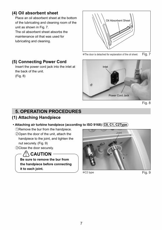
�The door is detached for explanation of the oil sheet.
Oil Absorbent Sheet
(4) Oil absorbent sheetPlace an oil absorbent sheet at the bottom of the lubricating and cleaning room of the unit as shown in Fig. 7.The oil absorbent sheet absorbs the maintenance oil that was used for lubricating and cleaning.
Fig. 7
(5) Connecting Power Cord Insert the power cord jack into the inlet at the back of the unit. (Fig. 8)
Fig. 8
(1) Attaching Handpiece5. OPERATION PROCEDURES
• Attaching air turbine handpiece (according to ISO 9168) C0, C1, C2TypeRemove the bur from the handpiece.Open the door of the unit, attach the handpiece to the joint, and tighten the nut securely. (Fig. 9)Close the door securely.
Fig. 9�C2 type
Be sure to remove the bur from the handpiece before connecting it to each joint.
CAUTION
1
2
3
Test Bur
Straight Handpiece
E-Type joint
Bur Insertion Hole
Inlet
Power Cord Jack
Joint
NutTighten
Joint
NutTighten

9
Connect the power cord plug to the power supply. Turn on the power switch, and the power indicator will light.Press the selector button number of the corresponding handpiece. First push will select "S", Short mode, second push "L", Long mode, and the third push "E", Extra Long mode. Those modes are indicated by the S, L and E lights.When two or more handpieces are mounted, select the right mode for each handpiece.Press the start key, and the Care 3 Plus automatically cleans and Iubricates the handpieces. The mode indicator flushes during the cleaning and lubrication cycle.When the cleaning and lubrication cycle is completed, the mode indicator turns on and the buzzer sounds to tell the completion of the cycle.Pressing the air key blows out air only from the joint with the mode indicator lighting to purge excess oil to some extent. Do so as is required.
(2) Cleaning and Lubricating
Fig. 13
� The figure in the parentheses, shows the total clean-lubricate-purge time.� Lubrication and cleaning in the extra long mode may cause oil to remain in a large quantity
in the handpiece.� Some products may not be used. Please consult ue.
Mode
Short Mode
Long Mode
Extra Long Mode
Handpiece
Air Turbine Handpiece
Contra Angle Handpiece
• All Handpieces (Make a selection when adequate lubrication and cleaning cannot be performed in the Short mode or Long mode.)
• Increasing Contra Angle Handpiece• Recreasing Contra Angle Handpiece• Air turbine Handpiece, Contra Angle Handpiece,
and Straight Handpiece by other makers.
Lubrication and cleaning time
About 35 sec.
About 45 sec.
About 50 sec.
Air time
About 60 sec.
About 80 sec.
About 90 sec.
Power IndicatorMode Indicators (S Lighting: Short Mode, L Lighting: Long Mode, E Lighting: Extra Long Mode)
Start KeyAir KeyError Indicator Selection Key (1: Left joint 2: Centear joint 3: Right joint)
Joint
Loosen
Nut
1
2
4
3
5
6

Release button Pin
Remobe the doorwith pressingtye release button
11
The door could be removed when cleaning or replacing the door gasket. To remove the door gasket, open the door, press the release button on right and remove the door. To mount the door, insert the pin into the left hole of the door and then insert the release button into the right hole until it locks. (Fig. 16)
6. DOOR
• Removing E-type handpiece (according to ISO 3964 type) C1, C2, C3TypeOpen the door after the mode indicator lights again and cleaning and lubrication cycle has completely finished. Pull out the handpiece in axial direction while pressing the fixing release button of the E-type joint. (Fig. 15)
Fig. 15
Remove and/or mount the door on a flat and stable surface with holding the body firmly.
CAUTION
Wipe off the maintenance oil collected at the bottoms of the cleaning chamber and the door. The collected oil could leak from the bottom of the door. Dispose of wiped cotton cloth as medical waste according to the lows and regulations of your country.
CAUTION�C2 type
Fig. 16
Fixing Release ButtonFixing Release Button

Oil Absorbent Sheet
13
• Replace oil absorbent sheets approx. every 50 times of use at the condition of 3 handpieces at Long mode.
• Dispose used oil absorbent sheets as medical waste according to the laws and regulations of your country.
CAUTION
Fig. 22Fig. 21
(3) Replacing O-ring C1, C2, C3TypePush out the worn O-ring with your thumb.Insert new O-ring in the O-ring groove.
�O-ring Set (Pack of 4) : Order No. Y900-185
Fig. 20(4) Replacing Air Filter
Pull out the air tube while pressing the connector ring. (Fig. 21)After removing the two screws, remove the air filter. (Fig. 22)Attach a new air filter following the removal steps in reverse. When attaching the air tube, securely insert it into the connector as far as it will go.
�Air Filter : Order No. U508-352
(2) Replacing Oil Absorbent SheetAfter opening the door and removing used oil absorbent sheet, attach new oil absorbent sheet as shown in Fig. 19.�Oil Absorbent Sheet Set (Pack of 20) :
Order No. Y900-186
Fig. 19�The door is detached for explanation of the oil sheet.
1
2
3
Connector ring
Air tube
Connector ring
Screw
Air filter
O-ringO-ring
1
2

15
(6) Draining Air Filter • When water eventually accumulates in
the case, press the drain button at the lower part of the case to drain the air filter. (Fig. 31)
• In addition to the air filter, drain the air supply to this device (air compressor etc.) at least once a week.
Fig. 31
The air supply (air compressor etc.) and air filter need to be clean and free from moisture. Drain the air compressor and air filter at least once a week. Moisture from the tank could mix in the maintenance oil and defeat the purpose of this device.
CAUTION
iSet them to main body with putting lock button and groove of main body together. Press case supporter up so that there is no gap with main body. Turn it to the right until lock button comes to the �mark. (Fig. 29)
oPut lock button up, then it is locked. (Fig. 30)�Air Filter Element : Order No. U508-353
Fig. 30Fig. 29
• Remove the air filter element after the air supply is stopped completely. • Remove the air filter element, apply the maintenance oil to O-ring (for case). • Replace the air filter element once every one to two years.
CAUTION
Drain button
Lock button
�mark
Lock button

17
When trouble is found, check the following items again before asking repairs. If none of these are applicable or the trouble is not remedied even after action has been taken, a failure of this product is suspected. Contact your dealer.
9. TROUBLESHOOTING
SolutionProbable Cause and CheckTrouble
Insert the power cord plug into the outlet.
Insert the power cord jack into the inlet.
Turn on the power.
Replace the fuse with recommended one.
Press the corresponding selection button to light mode indicator.
Close the door securely.
If the unit produces an operating sound, it has no problem. Check the air tube or the air supply. If the unit produces no operating sound, it is in failure. Contact your dealer.
Connect the air tube to the air connector securely.
Set the air pressure between 0.35-0.6 MPa (3.5-6.0 kgf/cm2) (50-85 psi).
Select an adequate mode according to the type of handpiece.
Connect the handpiece securely.
Select an adequate mode according to the type of handpiece.
Insert the contra angle handpiece with the bur insertion hole toward the door side.
Contact your dealer.
The power does not turn on.
The unit does not clean and lubricate.
The unit does not lubricate and clean efficiently.
Oil mist (misty solution) is released outside the unit.
Error indicator blink.
Is the power cord plug inserted into the outlet?
Is the power cord jack inserted into the inlet of the unit?
Is the power turned on?
Has the fuse burned?
Does the mode indicator light?
Is the door open? (Does the error indicator light?)
Remove the air tube, press all three selection buttons, and press start button, Does the unit produce an operating sound? (not a buzzar)
Is the air tube connected to the air connector securely?
Is the air pressure set within the specified range?
Is the mode set at the Short Mode?
Is the handpiece connected securely?
Has an appropriate mode selected?
Check if the bur insertion hole of the contra angle handpiece faces the door.
Malfunction of motor.
19
Manufacturer warrants its products to the original purchaser against defects in material and workmanship under normal practices of installation, use and servicing. Maintenance oil, Mist Filter, Oil Absorbent sheet, and O-ring etc. are expendable components, and are not covered by this warranty.
11. WARRANTY