Operation Manual Multi-parameter Transmitter M800 Manual Multi-parameter Transmitter M800...
118
Operation Manual Multi-parameter Transmitter M800 Transmitter Multi-parameter M800 52 121 825
Transcript of Operation Manual Multi-parameter Transmitter M800 Manual Multi-parameter Transmitter M800...
Operation Manual Multi-parameter Transmitter M800
Transmitter Multi-parameter M800 52 121 825

© 06 / 2012 Mettler-Toledo AG, CH-8606 Greifensee, Switzerland Transmitter M800 Printed in Switzerland 52 121 825
© 06 / 2012 Mettler-Toledo AG, CH-8606 Greifensee, Switzerland Transmitter M800 Printed in Switzerland 52 121 825
Operation Manual Multi-parameter Transmitter M800

Transmitter M800 4
© 06 / 2012 Mettler-Toledo AG, CH-8606 Greifensee, Switzerland Transmitter M800 Printed in Switzerland 52 121 825
Transmitter M800 5
© 06 / 2012 Mettler-Toledo AG, CH-8606 Greifensee, Switzerland Transmitter M800 Printed in Switzerland 52 121 825
Content
1 Introduction ___________________________________________________________________________________________ 9
2 Safety instructions _____________________________________________________________________________________ 102.1 Definition of equipment and documentation symbols and designations _______________________________________ 102.2 Correct disposal of the unit ________________________________________________________________________ 11
3 Unit overview _________________________________________________________________________________________ 123.1 Overview _______________________________________________________________________________________ 123.2 Display ________________________________________________________________________________________ 13
3.2.1 Start Screen _____________________________________________________________________________ 133.2.2 Activation Menu Screen ____________________________________________________________________ 13
3.3 Graphic Trend Measurement ________________________________________________________________________ 143.3.1 Activation Trend Display Screen ______________________________________________________________ 143.3.2 Settings for Trend Display Screen _____________________________________________________________ 153.3.3 Deactivation Trend Display Screen ____________________________________________________________ 15
3.4 Control / Navigation _______________________________________________________________________________ 163.4.1 Menu Structure ___________________________________________________________________________ 163.4.2 Navigation ______________________________________________________________________________ 17
3.4.2.1 Enter the Main Menus ____________________________________________________________ 173.4.2.2 Navigating the Menu Tree _________________________________________________________ 183.4.2.3 Exit a Menu ____________________________________________________________________ 183.4.2.4 Confirm Data and Values _________________________________________________________ 183.4.2.5 Return to the Menu Screen ________________________________________________________ 18
3.4.3 Entry of Data ____________________________________________________________________________ 183.4.4 Selection Menus __________________________________________________________________________ 183.4.5 ”Save changes” Dialog ____________________________________________________________________ 183.4.6 Security Passwords _______________________________________________________________________ 193.4.7 Display ________________________________________________________________________________ 19
4 Installation instruction __________________________________________________________________________________ 204.1 Unpacking and inspection of equipment _______________________________________________________________ 20
4.1.1 Panel cutout dimensional information ________________________________________________________ 204.1.2 Installation procedure _____________________________________________________________________ 214.1.3 Assembly _______________________________________________________________________________ 214.1.4 Dimension drawings ______________________________________________________________________ 224.1.5 Pipe mounting ___________________________________________________________________________ 22
4.2 Connection of power supply ________________________________________________________________________ 234.3 Terminal Definition _______________________________________________________________________________ 24
4.3.1 M800 2-channel _________________________________________________________________________ 244.3.2 M800 4-channel _________________________________________________________________________ 254.3.3 TB2 and TB4 – Terminal Assignment for Optical Oxygen Sensor, CO2 hi, and UniCond2e _________________ 264.3.4 TB2 and TB4 – Terminal Assignment for pH, Amp. Oxygen, Cond 4e, CO2 and O3 Sensors _______________ 264.3.5 TB3 – Terminal Assignment for Flow Sensors ___________________________________________________ 27
4.4 Connection of Flow Sensor _________________________________________________________________________ 274.4.1 Flow Sensor Input Wiring Kit ________________________________________________________________ 274.4.2 Kit Contents _____________________________________________________________________________ 284.4.3 Flow sensor wiring for Compatible Sensors _____________________________________________________ 284.4.4 Wiring for ”HIGH” type flow sensors __________________________________________________________ 284.4.5 Wiring for ”LOW” type flow sensors ___________________________________________________________ 314.4.6 Wiring for ”TYPE 2” flow sensors _____________________________________________________________ 31
5 Placing transmitter in, or out, of service ___________________________________________________________________ 325.1 Placing transmitter in service _______________________________________________________________________ 325.2 Placing transmitter out of service ____________________________________________________________________ 32
6 Guided Setup _________________________________________________________________________________________ 33
7 Calibration ___________________________________________________________________________________________ 347.1 Sensor Calibration ________________________________________________________________________________ 347.2 Calibration of UniCond2e Sensors ___________________________________________________________________ 34
7.2.1 Conductivity Calibration of UniCond2e Sensors __________________________________________________ 347.2.1.1 One-Point Calibration ____________________________________________________________ 367.2.1.2 Two-Point Calibration ____________________________________________________________ 377.2.1.3 Process Calibration _____________________________________________________________ 38
7.2.2 Temperature Calibration of UniCond2e Sensors __________________________________________________ 397.2.2.1 One-Point Calibration ____________________________________________________________ 397.2.2.2 Two-Point Calibration ____________________________________________________________ 40
Transmitter M800 6
© 06 / 2012 Mettler-Toledo AG, CH-8606 Greifensee, Switzerland Transmitter M800 Printed in Switzerland 52 121 825
7.3 Calibration of Cond4e Sensors ______________________________________________________________________ 427.3.1 One-Point Calibration _____________________________________________________________________ 427.3.2 Two-Point Calibration _____________________________________________________________________ 437.3.3 Process Calibration _______________________________________________________________________ 43
7.4 pH Calibration ___________________________________________________________________________________ 447.4.1 One-Point Calibration _____________________________________________________________________ 447.4.2 Two-Point Calibration _____________________________________________________________________ 457.4.3 Process Calibration _______________________________________________________________________ 45
7.5 ORP Calibration of pH Sensors ______________________________________________________________________ 467.6 Calibration of Amperometric Oxygen Sensors ___________________________________________________________ 46
7.6.1 One-Point Calibration _____________________________________________________________________ 477.6.2 Process Calibration _______________________________________________________________________ 47
7.7 Calibration of Optical Oxygen Sensors ________________________________________________________________ 487.7.1 One-Point Calibration _____________________________________________________________________ 487.7.2 Two-Point Calibration _____________________________________________________________________ 497.7.3 Process Calibration _______________________________________________________________________ 50
7.8 Calibration of Dissolved Carbon Dioxide Sensors ________________________________________________________ 507.8.1 One-Point Calibration _____________________________________________________________________ 507.8.2 Two-Point Calibration _____________________________________________________________________ 517.8.3 Process Calibration _______________________________________________________________________ 52
7.9 Calibration of Thermal Conductivity CO2 (C02 high) Sensors ______________________________________________ 527.9.1 One-Point Calibration ______________________________________________________________________ 537.9.2 Process Calibration _______________________________________________________________________ 53
7.10 Calibration of O3 Sensors __________________________________________________________________________ 547.10.1 One-Point Calibration _____________________________________________________________________ 547.10.2 Process Calibration _______________________________________________________________________ 55
7.11 Calibration of Flow Sensors ________________________________________________________________________ 567.11.1 One-Point Calibration _____________________________________________________________________ 567.11.2 Two-Point Calibration _____________________________________________________________________ 57
7.12 Sensor Verification ________________________________________________________________________________ 587.13 Edit Calibration Constants for Flow Sensors ____________________________________________________________ 597.14 UniCond2e Electronics Calibration ___________________________________________________________________ 597.15 Flow Meter Calibration ____________________________________________________________________________ 607.16 Flow Meter Verification ____________________________________________________________________________ 617.17 Analog Output Calibration __________________________________________________________________________ 617.18 Analog Input Calibration ___________________________________________________________________________ 627.19 Maintenance ____________________________________________________________________________________ 62
8 Configuration _________________________________________________________________________________________ 638.1 Measurement ___________________________________________________________________________________ 63
8.1.1 Channel Setup ___________________________________________________________________________ 638.1.2 Derived Measurements ____________________________________________________________________ 64
8.1.2.1 % Rejection measurement ________________________________________________________ 658.1.2.2 Calculated pH (Power Plant Applications only) ________________________________________ 658.1.2.3 Calculated CO2 (Power plant applications only) ________________________________________ 66
8.1.3 Display Mode ____________________________________________________________________________ 668.1.4 Parameter related Settings __________________________________________________________________ 67
8.1.4.1 Conductivity Settings _____________________________________________________________ 678.1.4.2 pH Settings ____________________________________________________________________ 688.1.4.3 Settings for Oxygen Measurement Based on Amperometric Sensors _________________________ 698.1.4.4 Settings for Oxygen Measurement Based on Optical Sensors ______________________________ 708.1.4.5 Dissolved Carbon Dioxide Settings __________________________________________________ 718.1.4.6 Settings for Thermal Conductivity Dissolved CO2 Measurement (CO2 hi) ____________________ 728.1.4.7 Settings for TOC Measurement _____________________________________________________ 728.1.4.8 Settings for Flow Measurement _____________________________________________________ 738.1.4.9 Deionization Capacity (DI-Cap™) __________________________________________________ 73
8.1.5 Concentration Curve Table __________________________________________________________________ 748.2 Analog Outputs __________________________________________________________________________________ 758.3 Set Points ______________________________________________________________________________________ 768.4 ISM Setup ______________________________________________________________________________________ 77
8.4.1 Sensor Monitor ___________________________________________________________________________ 778.4.2 CIP Cycle Limit ___________________________________________________________________________ 788.4.3 SIP Cycle Limit ___________________________________________________________________________ 798.4.4 AutoClave Cycle Limit _____________________________________________________________________ 808.4.5 DLI Stress Adjustment _____________________________________________________________________ 818.4.6 SAN Cycle Parameters _____________________________________________________________________ 818.4.7 Reset Counters for UniCond2e Sensors ________________________________________________________ 828.4.8 Set Calibration Interval for UniCond2e Sensors __________________________________________________ 82
Transmitter M800 7
© 06 / 2012 Mettler-Toledo AG, CH-8606 Greifensee, Switzerland Transmitter M800 Printed in Switzerland 52 121 825
8.5 General Alarm ___________________________________________________________________________________ 838.6 ISM / Sensor Alarm _______________________________________________________________________________ 838.7 Clean _________________________________________________________________________________________ 848.8 Display Setup ___________________________________________________________________________________ 848.9 Digital Inputs ____________________________________________________________________________________ 858.10 System ________________________________________________________________________________________ 858.11 PID Controller ___________________________________________________________________________________ 868.12 Service ________________________________________________________________________________________ 90
8.12.1 Set Analog Outputs _______________________________________________________________________ 908.12.2 Read Analog Outputs _____________________________________________________________ 908.12.3 Read Analog Inputs _______________________________________________________________________ 908.12.4 Set Relay _______________________________________________________________________________ 908.12.5 Read Relay _____________________________________________________________________________ 908.12.6 Read Digital Inputs _______________________________________________________________________ 908.12.7 Memory ________________________________________________________________________________ 918.12.8 Display ________________________________________________________________________________ 918.12.9 Calibrate TouchPad _______________________________________________________________________ 918.12.10 Channel Diagnostic _______________________________________________________________________ 91
8.13 Technical Service ________________________________________________________________________________ 918.14 User Management ________________________________________________________________________________ 928.15 Reset __________________________________________________________________________________________ 92
8.15.1 System Reset ____________________________________________________________________________ 928.15.2 Reset Sensor Calibration for Optical DO Sensors _________________________________________________ 938.15.3 Reset Sensor Calibration for UniCond2e Sensors _________________________________________________ 938.15.4 Reset Total Flow __________________________________________________________________________ 938.15.5 Reset for CO2 hi Measurement ______________________________________________________________ 94
8.16 RS485 Printer Output Configuration __________________________________________________________________ 948.17 USB Measurement Interface ________________________________________________________________________ 95
9 ISM _________________________________________________________________________________________________ 969.1 iMonitor ________________________________________________________________________________________ 969.2 Messages ______________________________________________________________________________________ 979.3 ISM Diagnostics _________________________________________________________________________________ 97
9.3.1 pH/ORP, Oxygen, O3 and Cond4e Sensors _____________________________________________________ 989.3.2 UniCond2e Sensors _______________________________________________________________________ 98
9.4 Calibration Data _________________________________________________________________________________ 999.4.1 Calibration Data for All ISM Sensors excluding UniCond2e _________________________________________ 999.4.2 Calibration Data for UniCond2e Sensors ______________________________________________________100
9.5 Sensor Info ____________________________________________________________________________________1009.6 HW / SW Version _______________________________________________________________________________1019.7 Log Book _____________________________________________________________________________________101
10 Wizards _____________________________________________________________________________________________10210.1 Set Wizard ____________________________________________________________________________________10210.2 Access to Wizards ______________________________________________________________________________102
11 Maintenance _________________________________________________________________________________________10311.1 Front panel cleaning _____________________________________________________________________________103
12 Troubleshooting ______________________________________________________________________________________10412.1 Warning- and Alarm Indication _____________________________________________________________________104
12.1.1 Warning Indication_______________________________________________________________________10412.1.2 Alarm Indication _________________________________________________________________________105
13 Accessories and Spare Parts ____________________________________________________________________________106
14 Specifications ________________________________________________________________________________________10714.1 General specifications ___________________________________________________________________________10714.2 Electrical specifications ___________________________________________________________________________10914.3 Mechanical specifications _________________________________________________________________________10914.4 Environmental specifications ______________________________________________________________________110
15 Warranty ____________________________________________________________________________________________111
16 Buffer tables _________________________________________________________________________________________11216.1 Standard pH buffers _____________________________________________________________________________112
16.1.1 Mettler-9 _______________________________________________________________________________11216.1.2 Mettler-10 _____________________________________________________________________________11316.1.3 NIST Technical Buffers ____________________________________________________________________11316.1.4 NIST standard buffers (DIN and JIS 19266: 2000–01) __________________________________________11416.1.5 Hach buffers ___________________________________________________________________________114
Transmitter M800 8
© 06 / 2012 Mettler-Toledo AG, CH-8606 Greifensee, Switzerland Transmitter M800 Printed in Switzerland 52 121 825
16.1.6 Ciba (94) buffers ________________________________________________________________________11516.1.7 Merck Titrisole, Riedel-de-Haën Fixanale _____________________________________________________11516.1.8 WTW buffers ___________________________________________________________________________11616.1.9 JIS Z 8802 buffers _______________________________________________________________________116
16.2 Dual membrane pH electrode buffers ________________________________________________________________11716.2.1 Mettler-pH / pNa buffers (Na+ 3.9M) _________________________________________________________117
Transmitter M800 9
© 06 / 2012 Mettler-Toledo AG, CH-8606 Greifensee, Switzerland Transmitter M800 Printed in Switzerland 52 121 825
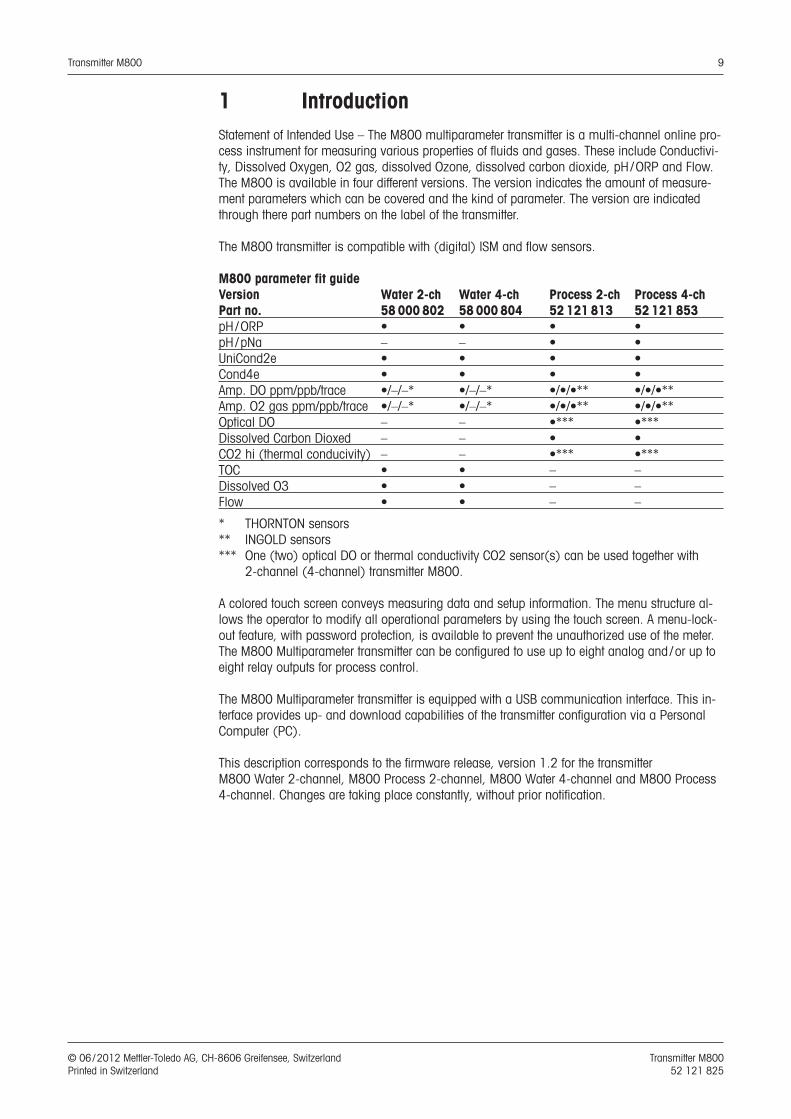
1 IntroductionStatement of Intended Use – The M800 multiparameter transmitter is a multi-channel online pro-cess instrument for measuring various properties of fluids and gases. These include Conductivi-ty, Dissolved Oxygen, O2 gas, dissolved Ozone, dissolved carbon dioxide, pH / ORP and Flow. The M800 is available in four different versions. The version indicates the amount of measure-ment parameters which can be covered and the kind of parameter. The version are indicated through there part numbers on the label of the transmitter.
The M800 transmitter is compatible with (digital) ISM and flow sensors.
M800 parameter fit guideVersion Water 2-ch Water 4-ch Process 2-ch Process 4-ch Part no. 58 000 802 58 000 804 52 121 813 52 121 853pH / ORP • • • •pH / pNa – – • •UniCond2e • • • •Cond4e • • • •Amp. DO ppm/ppb/trace •/–/–* •/–/–* •/•/•** •/•/•**Amp. O2 gas ppm/ppb/trace •/–/–* •/–/–* •/•/•** •/•/•**Optical DO – – •*** •***Dissolved Carbon Dioxed – – • •CO2 hi (thermal conducivity) – – •*** •*** TOC • • – –Dissolved O3 • • – –Flow • • – –
* THORNTON sensors** INGOLD sensors*** One (two) optical DO or thermal conductivity CO2 sensor(s) can be used together with
2-channel (4-channel) transmitter M800.
A colored touch screen conveys measuring data and setup information. The menu structure al-lows the operator to modify all operational parameters by using the touch screen. A menu-lock-out feature, with password protection, is available to prevent the unauthorized use of the meter. The M800 Multiparameter transmitter can be configured to use up to eight analog and / or up to eight relay outputs for process control.
The M800 Multiparameter transmitter is equipped with a USB communication interface. This in-terface provides up- and download capabilities of the transmitter configuration via a Personal Computer (PC).
This description corresponds to the firmware release, version 1.2 for the transmitter M800 Water 2-channel, M800 Process 2-channel, M800 Water 4-channel and M800 Process 4-channel. Changes are taking place constantly, without prior notification.
Transmitter M800 10
© 06 / 2012 Mettler-Toledo AG, CH-8606 Greifensee, Switzerland Transmitter M800 Printed in Switzerland 52 121 825
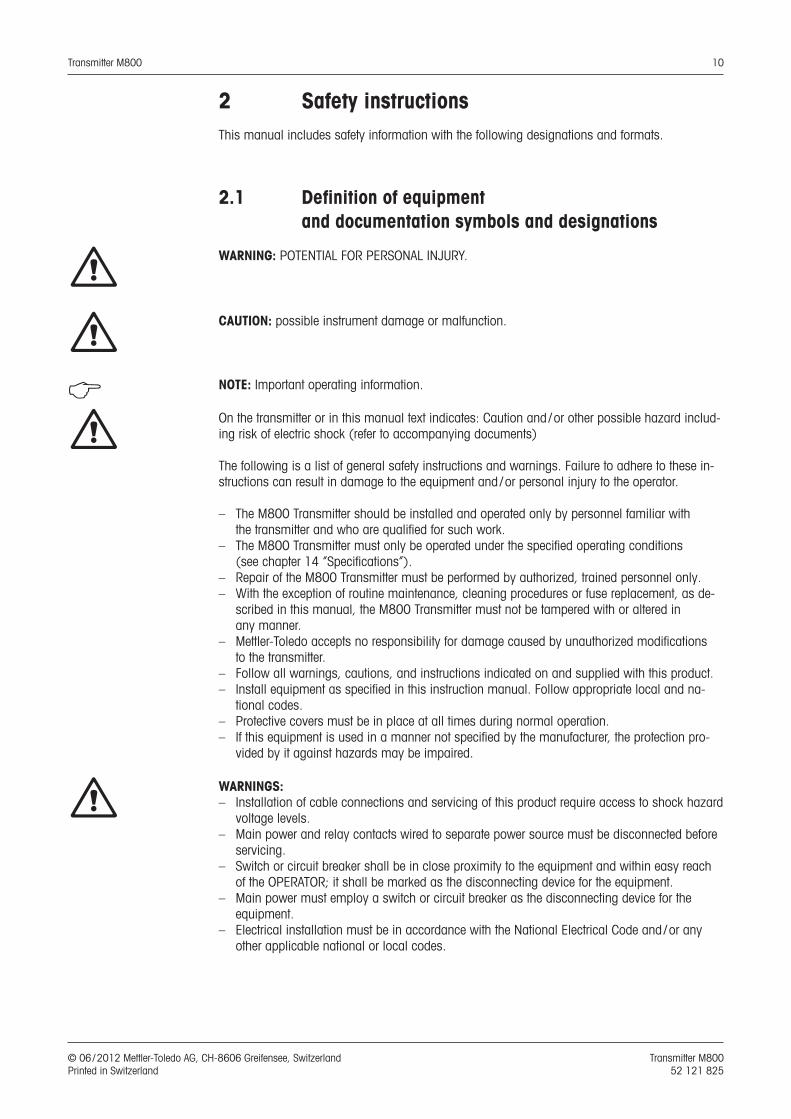
2 Safety instructionsThis manual includes safety information with the following designations and formats.
2.1 Definition of equipment and documentation symbols and designations
a WARNING: POTENTIAL FOR PERSONAL INJURY.
a CAUTION: possible instrument damage or malfunction.
h NOTE: Important operating information.
a On the transmitter or in this manual text indicates: Caution and / or other possible hazard includ-ing risk of electric shock (refer to accompanying documents)
The following is a list of general safety instructions and warnings. Failure to adhere to these in-structions can result in damage to the equipment and / or personal injury to the operator.
– The M800 Transmitter should be installed and operated only by personnel familiar with the transmitter and who are qualified for such work.
– The M800 Transmitter must only be operated under the specified operating conditions (see chapter 14 “Specifications”).
– Repair of the M800 Transmitter must be performed by authorized, trained personnel only. – With the exception of routine maintenance, cleaning procedures or fuse replacement, as de-
scribed in this manual, the M800 Transmitter must not be tampered with or altered in any manner.
– Mettler-Toledo accepts no responsibility for damage caused by unauthorized modifications to the transmitter.
– Follow all warnings, cautions, and instructions indicated on and supplied with this product.– Install equipment as specified in this instruction manual. Follow appropriate local and na-
tional codes.– Protective covers must be in place at all times during normal operation.– If this equipment is used in a manner not specified by the manufacturer, the protection pro-
vided by it against hazards may be impaired.
a WARNINGS:– Installation of cable connections and servicing of this product require access to shock hazard
voltage levels.– Main power and relay contacts wired to separate power source must be disconnected before
servicing.– Switch or circuit breaker shall be in close proximity to the equipment and within easy reach
of the OPERATOR; it shall be marked as the disconnecting device for the equipment.– Main power must employ a switch or circuit breaker as the disconnecting device for the
equipment.– Electrical installation must be in accordance with the National Electrical Code and / or any
other applicable national or local codes.
Transmitter M800 11
© 06 / 2012 Mettler-Toledo AG, CH-8606 Greifensee, Switzerland Transmitter M800 Printed in Switzerland 52 121 825
h NOTE: RELAY CONTROL ACTIONthe M800 transmitter relays will always de-energize on loss of power, equivalent to nor-mal state, regardless of relay state setting for powered operation. Configure any control system using these relays with fail-safe logic accordingly.
h NOTE: PROCESS UPSETSBecause process and safety conditions may depend on consistent operation of this trans-mitter, provide appropriate means to maintain operation during sensor cleaning, replace-ment or sensor or instrument calibration.
h NOTE: This is a 4-wire-product with an active 4–20 mA analog output. Please do not supply to terminal 3 to 10 of TB1 and terminal 1 to 8 of TB3.
2.2 Correct disposal of the unit
When the transmitter is finally removed from service, observe all local environmental regulations for proper disposal.
Transmitter M800 12
© 06 / 2012 Mettler-Toledo AG, CH-8606 Greifensee, Switzerland Transmitter M800 Printed in Switzerland 52 121 825
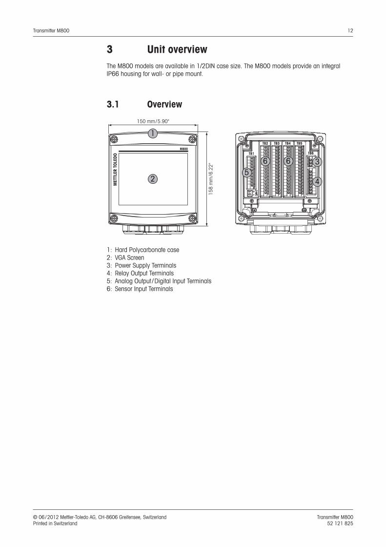
3 Unit overviewThe M800 models are available in 1/2DIN case size. The M800 models provide an integral IP66 housing for wall- or pipe mount.
3.1 Overview
150 mm/5.90"
158
mm
/6.2
2"
MET
TLER
TOL
EDO
M800
1
2
TB2
TB1
TB3 TB4 TB5
TB6
56 6 3
4
1: Hard Polycarbonate case2: VGA Screen3: Power Supply Terminals4: Relay Output Terminals5: Analog Output / Digital Input Terminals6: Sensor Input Terminals
Transmitter M800 13
© 06 / 2012 Mettler-Toledo AG, CH-8606 Greifensee, Switzerland Transmitter M800 Printed in Switzerland 52 121 825
3.2 Display
3.2.1 Start Screen
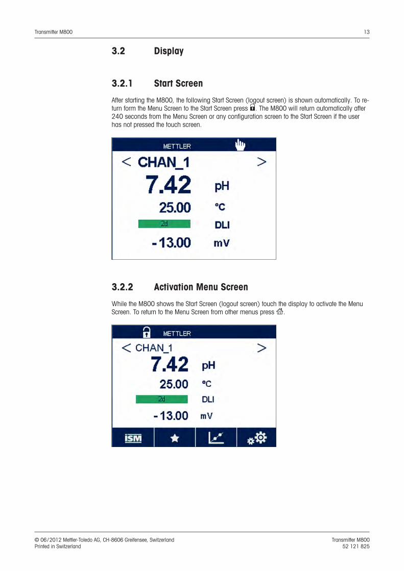
After starting the M800, the following Start Screen (logout screen) is shown automatically. To re-turn form the Menu Screen to the Start Screen press s. The M800 will return automatically after 240 seconds from the Menu Screen or any configuration screen to the Start Screen if the user has not pressed the touch screen.
3.2.2 Activation Menu Screen
While the M800 shows the Start Screen (logout screen) touch the display to activate the Menu Screen. To return to the Menu Screen from other menus press H.
Transmitter M800 14
© 06 / 2012 Mettler-Toledo AG, CH-8606 Greifensee, Switzerland Transmitter M800 Printed in Switzerland 52 121 825
3.3 Graphic Trend Measurement
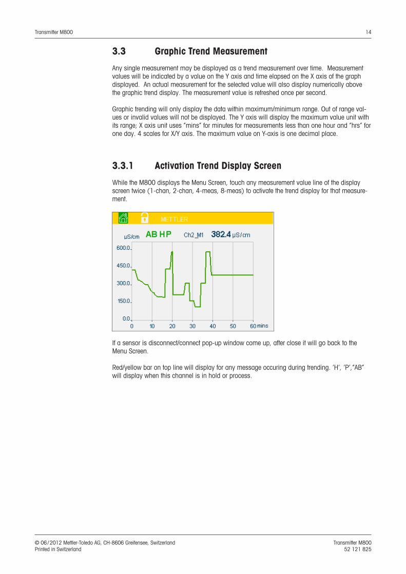
Any single measurement may be displayed as a trend measurement over time. Measurement values will be indicated by a value on the Y axis and time elapsed on the X axis of the graph displayed. An actual measurement for the selected value will also display numerically above the graphic trend display. The measurement value is refreshed once per second.
Graphic trending will only display the data within maximum/minimum range. Out of range val-ues or invalid values will not be displayed. The Y axis will display the maximum value unit with its range; X axis unit uses “mins” for minutes for measurements less than one hour and “hrs” for one day. 4 scales for X/Y axis. The maximum value on Y-axis is one decimal place.
3.3.1 Activation Trend Display Screen
While the M800 displays the Menu Screen, touch any measurement value line of the display screen twice (1-chan, 2-chan, 4-meas, 8-meas) to activate the trend display for that measure-ment.
If a sensor is disconnect/connect pop-up window come up, after close it will go back to the Menu Screen.
Red/yellow bar on top line will display for any message occuring during trending. ‘H’, ‘P’,”AB” will display when this channel is in hold or process.
Transmitter M800 15
© 06 / 2012 Mettler-Toledo AG, CH-8606 Greifensee, Switzerland Transmitter M800 Printed in Switzerland 52 121 825
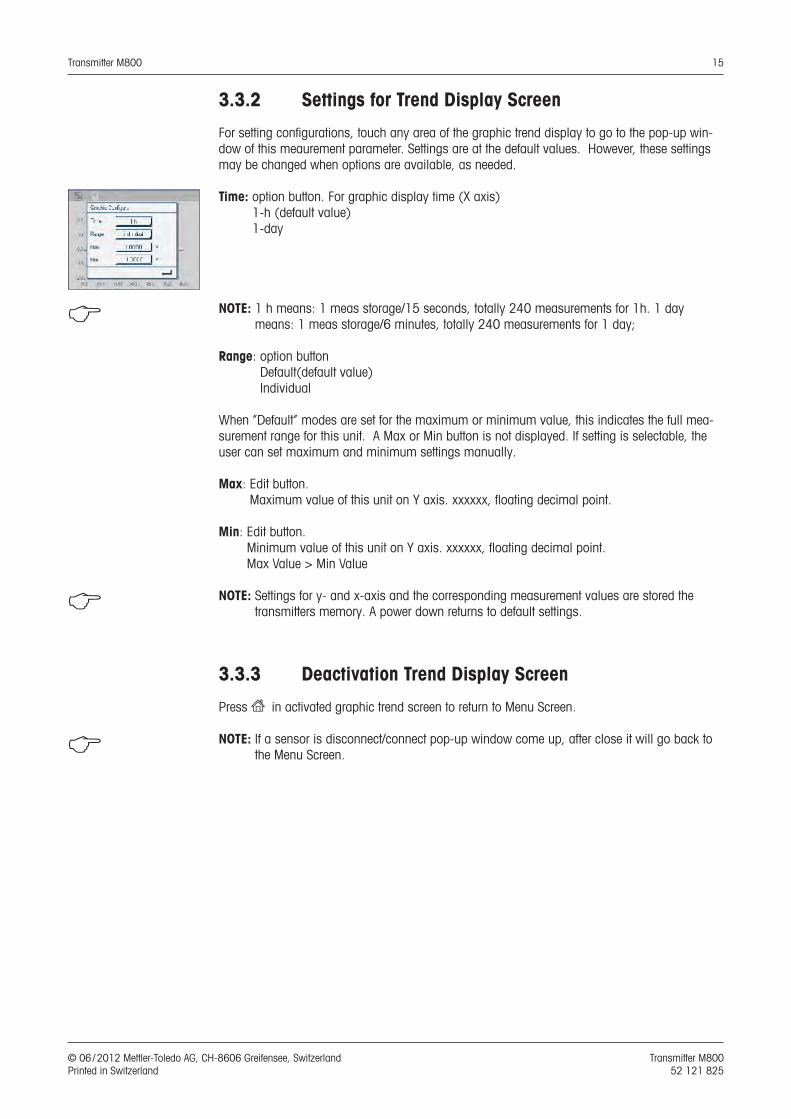
3.3.2 Settings for Trend Display Screen
For setting configurations, touch any area of the graphic trend display to go to the pop-up win-dow of this meaurement parameter. Settings are at the default values. However, these settings may be changed when options are available, as needed.
Time: option button. For graphic display time (X axis)1-h (default value) 1-day
h NOTE: 1 h means: 1 meas storage/15 seconds, totally 240 measurements for 1h. 1 day means: 1 meas storage/6 minutes, totally 240 measurements for 1 day;
Range: option buttonDefault(default value) Individual
When “Default” modes are set for the maximum or minimum value, this indicates the full mea-surement range for this unit. A Max or Min button is not displayed. If setting is selectable, the user can set maximum and minimum settings manually.
Max: Edit button.Maximum value of this unit on Y axis. xxxxxx, floating decimal point.
Min: Edit button.Minimum value of this unit on Y axis. xxxxxx, floating decimal point. Max Value > Min Value
h NOTE: Settings for y- and x-axis and the corresponding measurement values are stored the transmitters memory. A power down returns to default settings.
3.3.3 Deactivation Trend Display Screen
Press H in activated graphic trend screen to return to Menu Screen.
h NOTE: If a sensor is disconnect/connect pop-up window come up, after close it will go back to the Menu Screen.
Transmitter M800 16
© 06 / 2012 Mettler-Toledo AG, CH-8606 Greifensee, Switzerland Transmitter M800 Printed in Switzerland 52 121 825
3.4 Control / Navigation
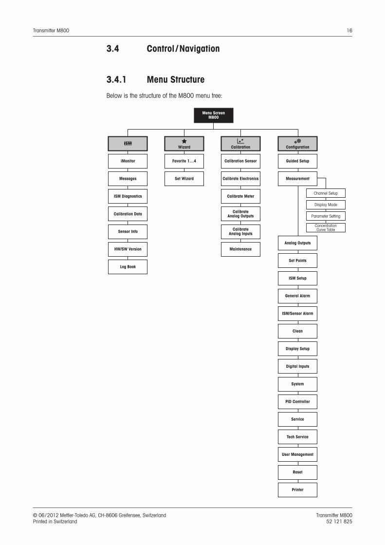
3.4.1 Menu Structure
Below is the structure of the M800 menu tree:
Menu ScreenM800
Guided Setup
Measurement
Analog Outputs
Set Points
ISM Setup
General Alarm
ISM/Sensor Alarm
Display Setup
Digital Inputs
System
PID Controller
Service
Tech Service
User Management
Reset
Printer
Clean
Channel Setup
Display Mode
Parameter Setting
Concentration Curve Table
cCalibration
Calibration Sensor
Calibrate Electronics
Calibrate Meter
Calibrate Analog Outputs
CalibrateAnalog Inputs
Maintenance
Favorite 1…4
Set Wizard
SWizard
i
iMonitor
Messages
ISM Diagnostics
Calibration Data
Sensor Info
HW/SW Version
Log Book
CConfiguration

Transmitter M800 17
© 06 / 2012 Mettler-Toledo AG, CH-8606 Greifensee, Switzerland Transmitter M800 Printed in Switzerland 52 121 825
3.4.2 Navigation
3.4.2.1 Enter the Main Menus
Activate the Menu Screen and press one of icons to enter the different main menus:
i ISM menu
S Wizard menu
c Calibration menu
C Configuration menu
Transmitter M800 18
© 06 / 2012 Mettler-Toledo AG, CH-8606 Greifensee, Switzerland Transmitter M800 Printed in Switzerland 52 121 825
3.4.2.2 Navigating the Menu Tree
To browse through the menus, press the open arrows > and/or <. To access a menu touch the corresponding arrow c in the same line.
3.4.2.3 Exit a Menu
Press p to exit the menu. Press H to return to the Menu Screen (see chapter 3.2.2 “Activation Menu Screen”).
3.4.2.4 Confirm Data and Values
Use the e key to confirm values. Press ESC and the values will not be taken over.
3.4.2.5 Return to the Menu Screen
Press H to return to the Menu Screen (see chapter 3.2.2 “Activation Menu Screen”). To return form the Menu Screen to the Start Screen press s.
3.4.3 Entry of Data
The M800 displays a keypad for modifying values. Press the e button and the transmitter will take over the value. Press the ESC button to exit the keypad without changing data.
h NOTE: For some value the unit can be modified. In this case the keypad shows a button with a u. To select another unit for the entered value on the keypad press the u button. To return again press the 0–9 button.
h NOTE: For some entries letters and/or numbers can be used. In that case the keypad shows a button ‘A,a,0’. Press this button to change between capital letters, small letters and numbers on the keypad.
3.4.4 Selection Menus
Some menus require a selection of a parameter / data. In this case the transmitter displays a pop up window. Press the according field to select the value. The pop window will be closed and the selection will be taken over.
3.4.5 ”Save changes” Dialog
If the M800 brings up the ”Save changes” dialog there are the follwoing options. No will discard the entered values, Yes will save changes made and Cancel will bring you back to continue configuring.
Transmitter M800 19
© 06 / 2012 Mettler-Toledo AG, CH-8606 Greifensee, Switzerland Transmitter M800 Printed in Switzerland 52 121 825
3.4.6 Security Passwords
The M800 transmitter allows a security lock-out of various menus. If the security lock-out feature of the transmitter has been enabled, a security password must be entered to allow ac-cess to the menu. See chapter 8.14 “User Management”.
3.4.7 Display
h NOTE: In the event of an alarm or other error condition the M800 Transmitter will display a flash-ing bar graph on the display. This bar graph will remain until the condition that caused it has been cleared (see chapter 12.1 “Warning- and Alarm Indication)”.
h NOTE: During calibrations, clean, Digital In with Analog Output / Relay / USB in Hold state, a flashing ”H” (Hold) will appear in the upper right corner of the display for the corresponding channel. This symbol will remain for 20 sec., after end of calibration. This symbol will remain for 20 seconds until after the calibration or clean is completed. This symbol will also disappear when Digital In is deactivated.
Transmitter M800 20
© 06 / 2012 Mettler-Toledo AG, CH-8606 Greifensee, Switzerland Transmitter M800 Printed in Switzerland 52 121 825
4 Installation instruction
4.1 Unpacking and inspection of equipment
Inspect the shipping container. If it is damaged, contact the shipper immediately for instructions. Do not discard the box.
If there is no apparent damage, unpack the container. Be sure all items shown on the packing list are present.
If items are missing, notify Mettler-Toledo immediately
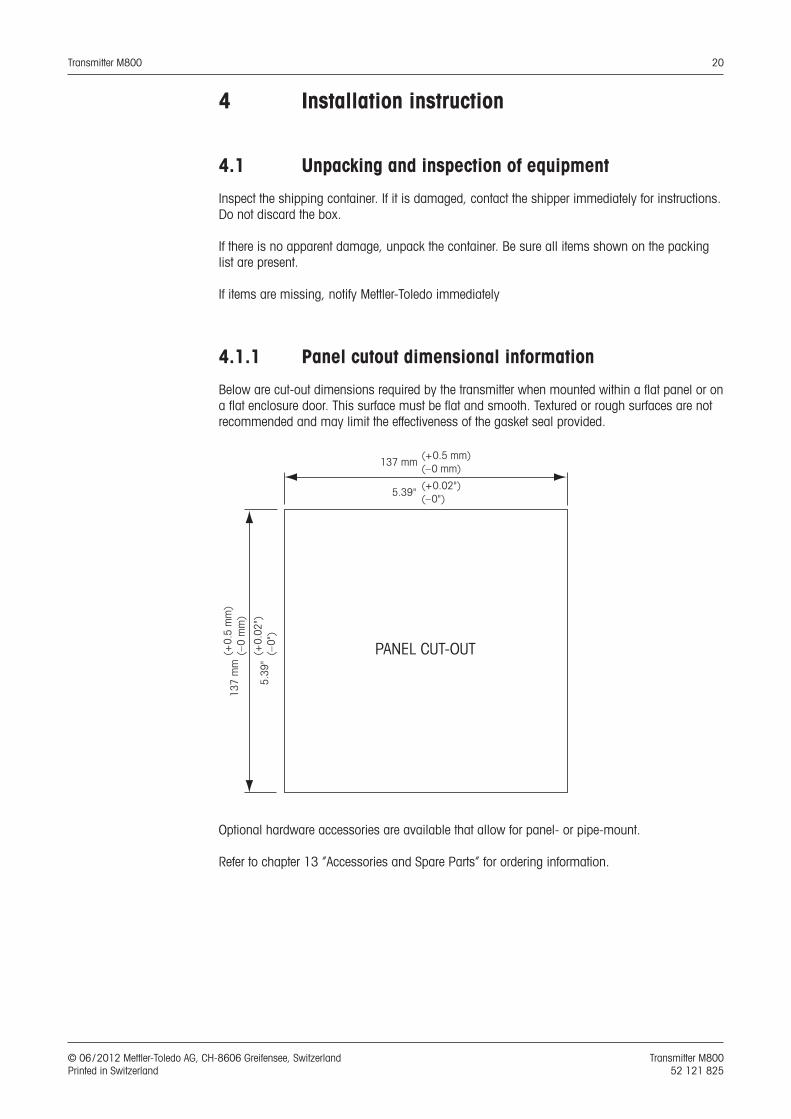
4.1.1 Panel cutout dimensional information
Below are cut-out dimensions required by the transmitter when mounted within a flat panel or on a flat enclosure door. This surface must be flat and smooth. Textured or rough surfaces are not recommended and may limit the effectiveness of the gasket seal provided.
5
.39"
(+ 0
.02"
)
(– 0
")
137
mm
(+ 0
.5 m
m)
(–
0 m
m)
PANEL CUT-OUT
5.39" (+ 0.02")
(– 0")
137 mm (+ 0.5 mm)
(– 0 mm)
Optional hardware accessories are available that allow for panel- or pipe-mount.
Refer to chapter 13 “Accessories and Spare Parts” for ordering information.

Transmitter M800 21
© 06 / 2012 Mettler-Toledo AG, CH-8606 Greifensee, Switzerland Transmitter M800 Printed in Switzerland 52 121 825
4.1.2 Installation procedure
General:– Orient the transmitter so that the cable grips face downward.– Wiring routed through the cable grips shall be suitable for use in wet locations.– In order provide IP66 enclosure ratings, all cable glands must be in place. Each cable gland
must be filled using a cable, or suitable Cable Gland Hole Seal.
For Pipe Mount:– Use only manufacturer-supplied components for pipe-mounting the M800 transmitter and in-
stall per the supplied instructions. See chapter 13 “Accessories and Spare Parts” for ordering information.
4.1.3 Assembly
1
2
3
1: 3 M20x1.5 cable glands2: 2 M25x1.5 cable glands3: 4 screws
Transmitter M800 22
© 06 / 2012 Mettler-Toledo AG, CH-8606 Greifensee, Switzerland Transmitter M800 Printed in Switzerland 52 121 825
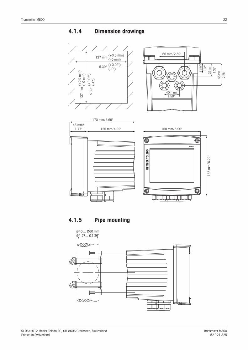
4.1.4 Dimension drawings
150 mm/5.90"125 mm/4.92"
170 mm/6.69"
45 mm/1.77"
158
mm
/6.2
2"
MET
TLER
TOL
EDO
M800
40 mm/
66 mm/2.59"
1.58"
2.28
"58
mm1.
38"
35 m
m0.
98"
25 m
m
5
.39"
(+ 0
.02"
)
(– 0
")
137
mm
(+ 0
.5 m
m)
(–
0 m
m)
5.39" (+ 0.02")
(– 0")
137 mm (+ 0.5 mm)
(– 0 mm)
4.1.5 Pipe mounting
Ø 40 ... Ø 60 mmØ 1.57... Ø 2.36"
Transmitter M800 23
© 06 / 2012 Mettler-Toledo AG, CH-8606 Greifensee, Switzerland Transmitter M800 Printed in Switzerland 52 121 825
4.2 Connection of power supply
All connections to the transmitter are made on the inside of all models.
a Be sure power to all wires is turned off before proceeding with the installation
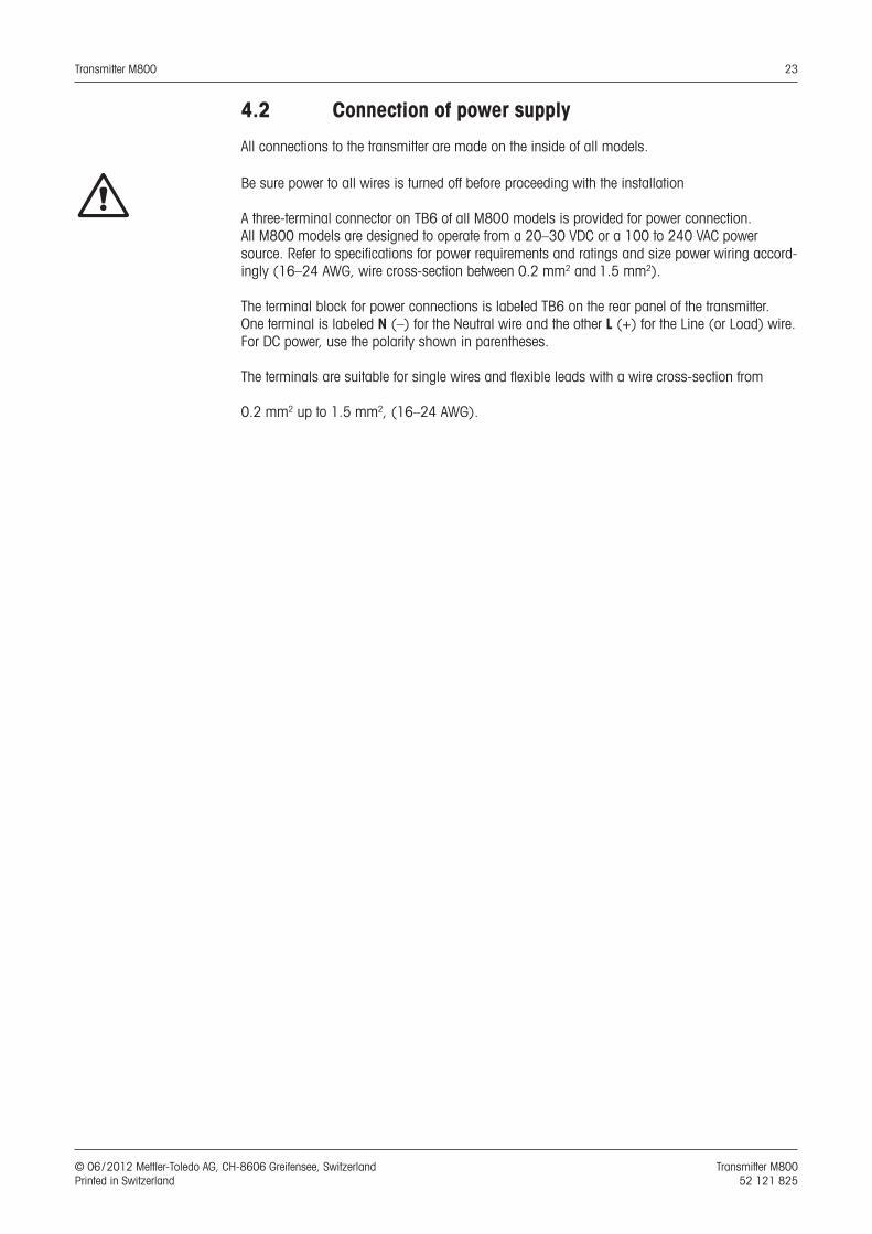
A three-terminal connector on TB6 of all M800 models is provided for power connection. All M800 models are designed to operate from a 20–30 VDC or a 100 to 240 VAC power source. Refer to specifications for power requirements and ratings and size power wiring accord-ingly (16–24 AWG, wire cross-section between 0.2 mm2 and 1.5 mm2).
The terminal block for power connections is labeled TB6 on the rear panel of the transmitter. One terminal is labeled N (–) for the Neutral wire and the other L (+) for the Line (or Load) wire. For DC power, use the polarity shown in parentheses.
The terminals are suitable for single wires and flexible leads with a wire cross-section from
0.2 mm2 up to 1.5 mm2, (16–24 AWG).

Transmitter M800 24
© 06 / 2012 Mettler-Toledo AG, CH-8606 Greifensee, Switzerland Transmitter M800 Printed in Switzerland 52 121 825
4.3 Terminal Definition
4.3.1 M800 2-channel
Power connections:N for Neutral and L for Line, for 100 to 240 VAC or 20–30 VDC.
Terminal number TB1 TB2
(ISM Ch1,2) TB3 TB4 TB5 TB6
1 DI1+ DI2+ Aout5+
Not
inst
alle
d
AI1+ L
2 DI1– DI2– Aout5– AI1- N
3 Aout1+ 1-Wire_Ch1 Aout6+ DI4+ Ground
4 Aout1– GND5V_Ch1 Aout6– DI4– Relay1_NC
5 Aout2+ RS485B_Ch1 Aout7+ DI5+ Relay1_COM
6 Aout2– RS485A_Ch1 Aout7– DI5– Relay2_NO
7 Aout3+ GND5V_Ch1 Aout8+ DI6+ Relay2_COM
8 Aout3– 5V_Ch1 Aout8- DI6– Relay3_NO
9 Aout4+ 24V_Ch2 Ain_Ch5 Relay5_NO Relay3_COM
10 Aout4– GND24V_Ch2 AJ_Ch5 Relay5_COM Relay4_NO
11 n. a. 1-Wire_Ch2 5V_Ch5 Relay6_NO Relay4_COM
12 n. a. GND5V_Ch2 GND5V_Ch5 Relay6_COM n. a.
13 n. a. RS485B_Ch2 Bin_Ch6 Relay7_NO n. a.
14 n. a. RS485A_Ch2 BJ_Ch6 Relay7_COM n. a.
15 n. a. GND5V_Ch2 5V_Ch6 Relay8_NC n. a.
16 n. a. 5V_Ch2 GND5V_Ch6 Relay8_COM n. a.
TB2 TB3 TB4 TB5
TB6TB1
NO: normally open (contact open if un-actuated). AO: Analog Output NC: normally closed (contact closed if un-actuated). DI: Digital Input Ain: AJ: Bin: BJ: n.a. not available
h NOTE: This is a 4-wire-product with an active 4–20 mA analog output. Please do not supply to terminal no. 3 to 10 of TB1 and 1 to 8 of TB3.
Transmitter M800 25
© 06 / 2012 Mettler-Toledo AG, CH-8606 Greifensee, Switzerland Transmitter M800 Printed in Switzerland 52 121 825
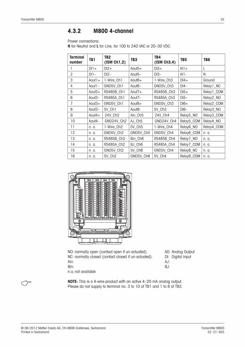
4.3.2 M800 4-channel
Power connections:N for Neutral and L for Line, for 100 to 240 VAC or 20–30 VDC.
Terminal number TB1 TB2
(ISM Ch1,2) TB3 TB4 (ISM Ch3,4) TB5 TB6
1 DI1+ DI2+ Aout5+ DI3+ AI1+ L
2 DI1– DI2– Aout5– DI3– AI1- N
3 Aout1+ 1-Wire_Ch1 Aout6+ 1-Wire_Ch3 DI4+ Ground
4 Aout1– GND5V_Ch1 Aout6– GND5V_Ch3 DI4– Relay1_NC
5 Aout2+ RS485B_Ch1 Aout7+ RS485B_Ch3 DI5+ Relay1_COM
6 Aout2– RS485A_Ch1 Aout7– RS485A_Ch3 DI5– Relay2_NO
7 Aout3+ GND5V_Ch1 Aout8+ GND5V_Ch3 DI6+ Relay2_COM
8 Aout3– 5V_Ch1 Aout8- 5V_Ch3 DI6– Relay3_NO
9 Aout4+ 24V_Ch2 Ain_Ch5 24V_Ch4 Relay5_NO Relay3_COM
10 Aout4– GND24V_Ch2 AJ_Ch5 GND24V_Ch4 Relay5_COM Relay4_NO
11 n. a. 1-Wire_Ch2 5V_Ch5 1-Wire_Ch4 Relay6_NO Relay4_COM
12 n. a. GND5V_Ch2 GND5V_Ch5 GND5V_Ch4 Relay6_COM n. a.
13 n. a. RS485B_Ch2 Bin_Ch6 RS485B_Ch4 Relay7_NO n. a.
14 n. a. RS485A_Ch2 BJ_Ch6 RS485A_Ch4 Relay7_COM n. a.
15 n. a. GND5V_Ch2 5V_Ch6 GND5V_Ch4 Relay8_NC n. a.
16 n. a. 5V_Ch2 GND5V_Ch6 5V_Ch4 Relay8_COM n. a.
TB2
TB1
TB3 TB4 TB5
TB6
NO: normally open (contact open if un-actuated). AO: Analog Output NC: normally closed (contact closed if un-actuated). DI: Digital Input Ain: AJ: Bin: BJ: n.a. not available
h NOTE: This is a 4-wire-product with an active 4–20 mA analog output. Please do not supply to terminal no. 3 to 10 of TB1 and 1 to 8 of TB3.
Transmitter M800 26
© 06 / 2012 Mettler-Toledo AG, CH-8606 Greifensee, Switzerland Transmitter M800 Printed in Switzerland 52 121 825
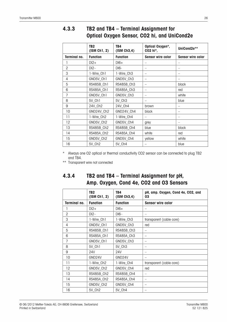
4.3.3 TB2 and TB4 – Terminal Assignment for Optical Oxygen Sensor, CO2 hi, and UniCond2e
TB2(ISM Ch1, 2)
TB4 (ISM Ch3,4)
Optical Oxygen*, CO2 hi*, UniCond2e**
Terminal no. Function Function Sensor wire color Sensor wire color
1 DI2+ DI6+ – –
2 DI2– DI6- – –
3 1-Wire_Ch1 1-Wire_Ch3 – –
4 GND5V_Ch1 GND5V_Ch3 – –
5 RS485B_Ch1 RS485B_Ch3 – black
6 RS485A_Ch1 RS485A_Ch3 – red
7 GND5V_Ch1 GND5V_Ch3 – white
8 5V_Ch1 5V_Ch3 – blue
9 24V_Ch2 24V_Ch4 brown –
10 GND24V_Ch2 GND24V_Ch4 black –
11 1-Wire_Ch2 1-Wire_Ch4 – –
12 GND5V_Ch2 GND5V_Ch4 grey –
13 RS485B_Ch2 RS485B_Ch4 blue black
14 RS485A_Ch2 RS485A_Ch4 white red
15 GND5V_Ch2 GND5V_Ch4 yellow white
16 5V_Ch2 5V_Ch4 – blue
* Always one O2 optical or thermal conductivity CO2 sensor can be connected to plug TB2 and TB4.** Transparent wire not connected
4.3.4 TB2 and TB4 – Terminal Assignment for pH, Amp. Oxygen, Cond 4e, CO2 and O3 Sensors
TB2(ISM Ch1, 2)
TB4 (ISM Ch3,4)
pH, amp. Oxygen, Cond 4e, CO2, and O3
Terminal no. Function Function Sensor wire color 1 DI2+ DI6+ –
2 DI2– DI6– –
3 1-Wire_Ch1 1-Wire_Ch3 transparent (cable core)
4 GND5V_Ch1 GND5V_Ch3 red
5 RS485B_Ch1 RS485B_Ch3 –
6 RS485A_Ch1 RS485A_Ch3 –
7 GND5V_Ch1 GND5V_Ch3 –
8 5V_Ch1 5V_Ch3 –
9 24V 24V –
10 GND24V GND24V –
11 1-Wire_Ch2 1-Wire_Ch4 transparent (cable core)
12 GND5V_Ch2 GND5V_Ch4 red
13 RS485B_Ch2 RS485B_Ch4 –
14 RS485A_Ch2 RS485A_Ch4 –
15 GND5V_Ch2 GND5V_Ch4 –
16 5V_Ch2 5V_Ch4 –
Transmitter M800 27
© 06 / 2012 Mettler-Toledo AG, CH-8606 Greifensee, Switzerland Transmitter M800 Printed in Switzerland 52 121 825
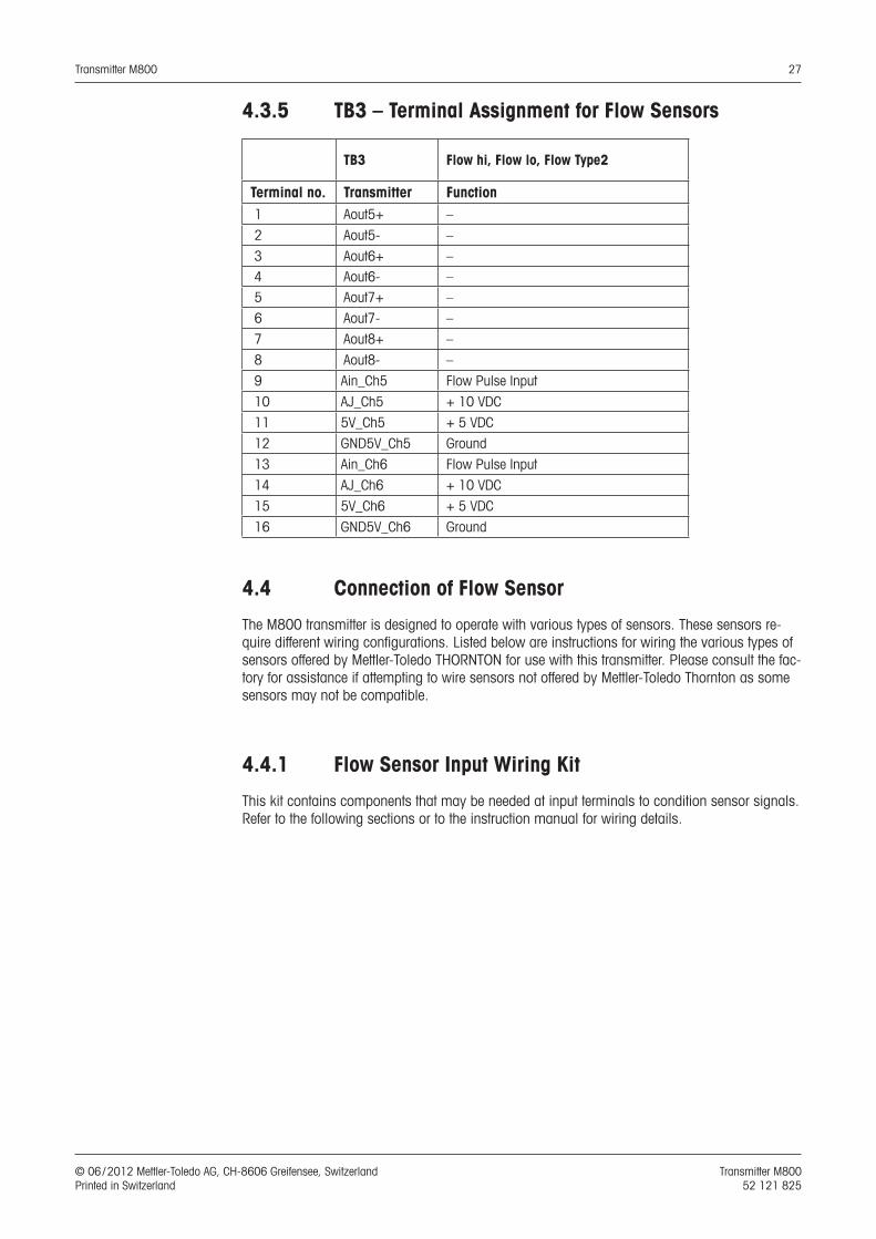
4.3.5 TB3 – Terminal Assignment for Flow Sensors
TB3 Flow hi, Flow lo, Flow Type2
Terminal no. Transmitter Function 1 Aout5+ –
2 Aout5- –
3 Aout6+ – 4 Aout6- – 5 Aout7+ –
6 Aout7- –
7 Aout8+ –
8 Aout8- –
9 Ain_Ch5 Flow Pulse Input
10 AJ_Ch5 + 10 VDC
11 5V_Ch5 + 5 VDC
12 GND5V_Ch5 Ground
13 Ain_Ch6 Flow Pulse Input
14 AJ_Ch6 + 10 VDC
15 5V_Ch6 + 5 VDC
16 GND5V_Ch6 Ground
4.4 Connection of Flow Sensor
The M800 transmitter is designed to operate with various types of sensors. These sensors re-quire different wiring configurations. Listed below are instructions for wiring the various types of sensors offered by Mettler-Toledo THORNTON for use with this transmitter. Please consult the fac-tory for assistance if attempting to wire sensors not offered by Mettler-Toledo Thornton as some sensors may not be compatible.
4.4.1 Flow Sensor Input Wiring Kit
This kit contains components that may be needed at input terminals to condition sensor signals. Refer to the following sections or to the instruction manual for wiring details.
Transmitter M800 28
© 06 / 2012 Mettler-Toledo AG, CH-8606 Greifensee, Switzerland Transmitter M800 Printed in Switzerland 52 121 825
4.4.2 Kit Contents
This kit contains the following items:
− 4x Wire nuts
− 4x 10K ohm resistors for use with Burket 8020 and 8030 type sensors, and GF Signet 2500-series sensors.
− 4x 1K ohm resistors for use with Data Industrial 200-series and Fluidyne insertion type sensors.
− 4x 0.33uF, 50 V capacitors for use with Berket 8020 and 8030 type sensors, Data Industrial 200-series and 4000-series sensors, GF Signet 2500-series sensors, Sanitary Turbine-Type sensors, Fluidyne insertion type sensors and Racine Federated (Formerly Asahi/America) vor-tex-style sensors.
4.4.3 Flow sensor wiring for Compatible Sensors
The following sections provide wiring information to properly connect various compatible flow sensors to the M800 transmitter. When using the Configuration menu of the transmitter to setup the flow sensor, the first prompt asks to select the TYPE of flow sensor being connected.
There are three choices as follows:
High: All flow sensors described in Section 4.4.4Low: P515 Signet flow sensors only, described in section 4.4.5Type 2: Asahi flow sensors, described in Section 4.4.6
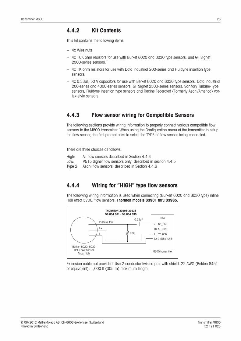
4.4.4 Wiring for ”HIGH” type flow sensors
The following wiring information is used when connecting (Burkert 8020 and 8030 type) inline Hall effect 5VDC, flow sensors. Thornton models 33901 thru 33935.
Extension cable not provided. Use 2-conductor twisted pair with shield, 22 AWG (Belden 8451 or equivalent), 1,000 ft (305 m) maximum length.
THORNTON 33901-3393558 034 601 - 58 034 635
Burkert 8020, 8030Hall-Effect Sensor
Type: highM800 transmitter
L–
Pulse output
L+
10K
0.33uF TB 3
9 Ain_Ch5
10 AJ_Ch5
11 5V_Ch5
12 GND5V_Ch5

Transmitter M800 29
© 06 / 2012 Mettler-Toledo AG, CH-8606 Greifensee, Switzerland Transmitter M800 Printed in Switzerland 52 121 825
The following wiring information is used when connecting Badger (formerly Data Industrial 200-Series) forward-swept paddlewheel type flow sensors. Thornton models 33142 thru 33145 and 33159 thru 33162 and 33273.
Extension cable provided with sensor. Use 2-conductor twisted pair with shield 20 AWG (Belden 9320 or equivalent) to extend length to 2000 ft (610 m) max.
The following wiring information is used when connecting Badger (formerly Data Industrial 4000-Series) forward-swept paddlewheel type flow sensors. Thornton models 33174 thru 33177 and 33171 and 33172.
20 ft (6.1 m) extension cable provided with sensor. Use 3-conductor with shield, 20 AWG (Belden 9364 or equivalent) to extend length to 2000 ft (610 m) maximum.
The following wiring information is used when connecting (GF Signet 2500-Series) Hall Effect paddlewheel type flow sensors. Thornton models 33282, 33285, 33287, 33298 thru 33305.
25 ft (7.6 m) extension cable provided with sensor. Use 2-conductor with shield, 22 AWG (Belden 8451 or equivalent) to extend length to 1000 ft (305 m) maximum.
THORNTON 33142-3314558 034 201 - 58 034 204
M800 transmitter
Shield
Red
Black
1K
0.33uF TB 3
9 Ain_Ch5
10 AJ_Ch5
11 5V_Ch5
12 GND5V_Ch5
Badger(formerly Data Industrial 200 Series)
Flow SensorsType: High
THORNTON 33174-33177, 33171, 3317258 034 207 - 58 034 211, 58 034 226
M800 transmitter
Shield
Red
Clear
Black
0.33uF TB 3
9 Ain_Ch5
10 AJ_Ch5
11 5V_Ch5
12 GND5V_Ch5
Badger(formerly Data Industrial 4000 Series)
Flow SensorsType: High
THORNTON 33282, 33285, 33287, 33298 - 3330558 034 227, 58 034 230, 58 034 232 - 58 034 240
Signet 2507, 2536, 2540Hall-Effect Sensor
Type: highM800 transmitter
Shield
Red
Black
10K
0.33uF TB 3
9 Ain_Ch5
10 AJ_Ch5
11 5V_Ch5
12 GND5V_Ch5

Transmitter M800 30
© 06 / 2012 Mettler-Toledo AG, CH-8606 Greifensee, Switzerland Transmitter M800 Printed in Switzerland 52 121 825
The following wiring information is used when connecting Sanitary Turbine type flow sensors. Thornton models 33336 thru 33377 (Hoffer) and 33441 thru 33450 (Sponsler).
20 ft (6.1 m) extension cable provided with sensor. Use 3-conductor with shield, 20 AWG (Belden 9364 or equivalent) to extend length to 3000 ft (915 m) maximum.
20 ft (6.1 m) extension cable provided with sensor. Use 3-conductor with shield, 20 AWG (Belden 9364 or equivalent) to extend length to 3000 ft (915 m) maximum.
The following wiring information is used when connecting Spirax Sarco/Emco flow (formerly Fluidyne) insertion type flow sensors. Thornton models 33358 thru 33375.
Extension cable not provided. Use 2-conductor twisted pair with shield, 20 AWG (Belden 9320 or equivalent), 2000 ft (610 m) maximum length.
THORNTON 3336-33348, 33376, 3337758 034 270 - 58 034 282, 58 034 303, 58 034 304
M800 transmitter
Shield
Red
White
Black
0.33uF TB 3
9 Ain_Ch5
10 AJ_Ch5
11 5V_Ch5
12 GND5V_Ch5
Hoffer Turbine SensorsType: High
THORNTON 33441-3345058 034 516 - 58 034 525
M800 transmitter
Shield
Red
Orange
Black
0.33uF TB 3
9 Ain_Ch5
10 AJ_Ch5
11 5V_Ch5
12 GND5V_Ch5
Sponsler Turbine SensorType: High
THORNTON 33358 - 3337558 034 285 - 58 034 302
M800 transmitter
Shield
(+)
(–)
1K
0.33uF TB 3
9 Ain_Ch5
10 AJ_Ch5
11 5V_Ch5
12 GND5V_Ch5
Spirax Sarco/Emco flow(formerly Fluidyne)
Insertion Vortex SensorType: High
Transmitter M800 31
© 06 / 2012 Mettler-Toledo AG, CH-8606 Greifensee, Switzerland Transmitter M800 Printed in Switzerland 52 121 825
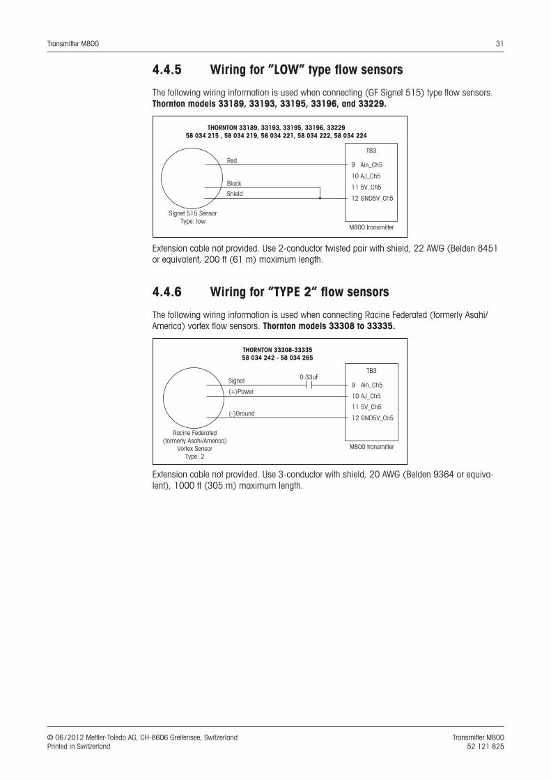
4.4.5 Wiring for ”LOW” type flow sensors
The following wiring information is used when connecting (GF Signet 515) type flow sensors. Thornton models 33189, 33193, 33195, 33196, and 33229.
Extension cable not provided. Use 2-conductor twisted pair with shield, 22 AWG (Belden 8451 or equivalent, 200 ft (61 m) maximum length.
4.4.6 Wiring for ”TYPE 2” flow sensors
The following wiring information is used when connecting Racine Federated (formerly Asahi/America) vortex flow sensors. Thornton models 33308 to 33335.
Extension cable not provided. Use 3-conductor with shield, 20 AWG (Belden 9364 or equiva-lent), 1000 ft (305 m) maximum length.
THORNTON 33189, 33193, 33195, 33196, 3322958 034 215 , 58 034 219, 58 034 221, 58 034 222, 58 034 224
M800 transmitter
Shield
Red
Black
TB 3
9 Ain_Ch5
10 AJ_Ch5
11 5V_Ch5
12 GND5V_Ch5
Signet 515 SensorType: low
THORNTON 33308-3333558 034 242 - 58 034 265
M800 transmitter
(-)Ground
Signal
(+)Power
TB 3
9 Ain_Ch5
10 AJ_Ch5
11 5V_Ch5
12 GND5V_Ch5
Racine Federated(formerly Asahi/America)
Vortex SensorType: 2
0.33uF
Transmitter M800 32
© 06 / 2012 Mettler-Toledo AG, CH-8606 Greifensee, Switzerland Transmitter M800 Printed in Switzerland 52 121 825
5 Placing transmitter in, or out, of service
5.1 Placing transmitter in service
a After connecting the transmitter to power supply circuit, it will be active as soon as the circuit is powered.
5.2 Placing transmitter out of service
First disconnect the unit from the main power source, then disconnect all remaining electrical connections. Remove the unit from the panel. Use the installation instruction in this manual as reference for dis-assembling mounting hardware.
All transmitter settings stored in memory are non volatile.
Transmitter M800 33
© 06 / 2012 Mettler-Toledo AG, CH-8606 Greifensee, Switzerland Transmitter M800 Printed in Switzerland 52 121 825
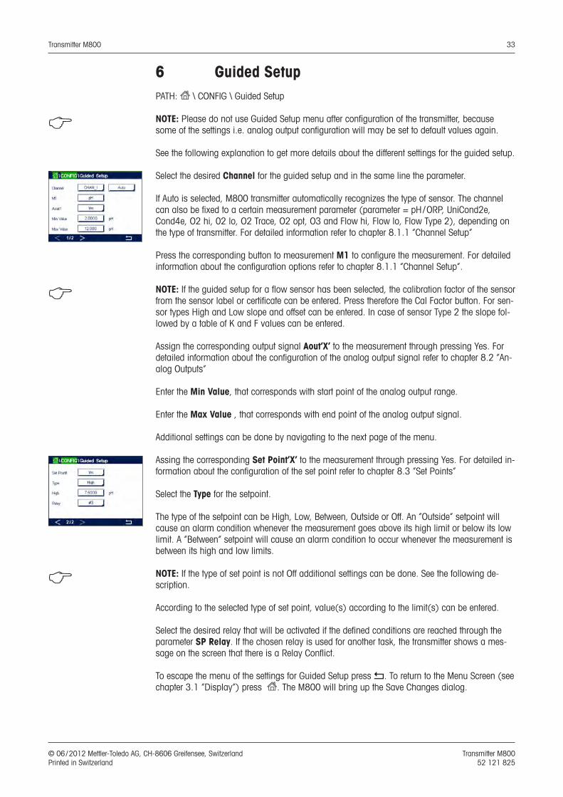
6 Guided SetupPATH: H \ CONFIG \ Guided Setup
h NOTE: Please do not use Guided Setup menu after configuration of the transmitter, because some of the settings i.e. analog output configuration will may be set to default values again.
See the following explanation to get more details about the different settings for the guided setup.
Select the desired Channel for the guided setup and in the same line the parameter.
If Auto is selected, M800 transmitter automatically recognizes the type of sensor. The channel can also be fixed to a certain measurement parameter (parameter = pH / ORP, UniCond2e, Cond4e, O2 hi, 02 lo, O2 Trace, O2 opt, O3 and Flow hi, Flow lo, Flow Type 2), depending on the type of trans mitter. For detailed information refer to chapter 8.1.1 ”Channel Setup”
Press the corresponding button to measurement M1 to configure the measurement. For detailed information about the configuration options refer to chapter 8.1.1 ”Channel Setup”.
h NOTE: If the guided setup for a flow sensor has been selected, the calibration factor of the sensor from the sensor label or certificate can be entered. Press therefore the Cal Factor button. For sen-sor types High and Low slope and offset can be entered. In case of sensor Type 2 the slope fol-lowed by a table of K and F values can be entered.
Assign the corresponding output signal Aout’X’ to the measurement through pressing Yes. For detailed information about the configuration of the analog output signal refer to chapter 8.2 ”An-alog Outputs”
Enter the Min Value, that corresponds with start point of the analog output range.
Enter the Max Value , that corresponds with end point of the analog output signal.
Additional settings can be done by navigating to the next page of the menu.
Assing the corresponding Set Point’X’ to the measurement through pressing Yes. For detailed in-formation about the configuration of the set point refer to chapter 8.3 ”Set Points”
Select the Type for the setpoint.
The type of the setpoint can be High, Low, Between, Outside or Off. An ”Outside” setpoint will cause an alarm condition whenever the measurement goes above its high limit or below its low limit. A ”Between” setpoint will cause an alarm condition to occur whenever the measurement is between its high and low limits.
h NOTE: If the type of set point is not Off additional settings can be done. See the following de-scription.
According to the selected type of set point, value(s) according to the limit(s) can be entered.
Select the desired relay that will be activated if the defined conditions are reached through the parameter SP Relay. If the chosen relay is used for another task, the transmitter shows a mes-sage on the screen that there is a Relay Conflict.
To escape the menu of the settings for Guided Setup press p. To return to the Menu Screen (see chapter 3.1 “Display”) press H. The M800 will bring up the Save Changes dialog.
Transmitter M800 34
© 06 / 2012 Mettler-Toledo AG, CH-8606 Greifensee, Switzerland Transmitter M800 Printed in Switzerland 52 121 825
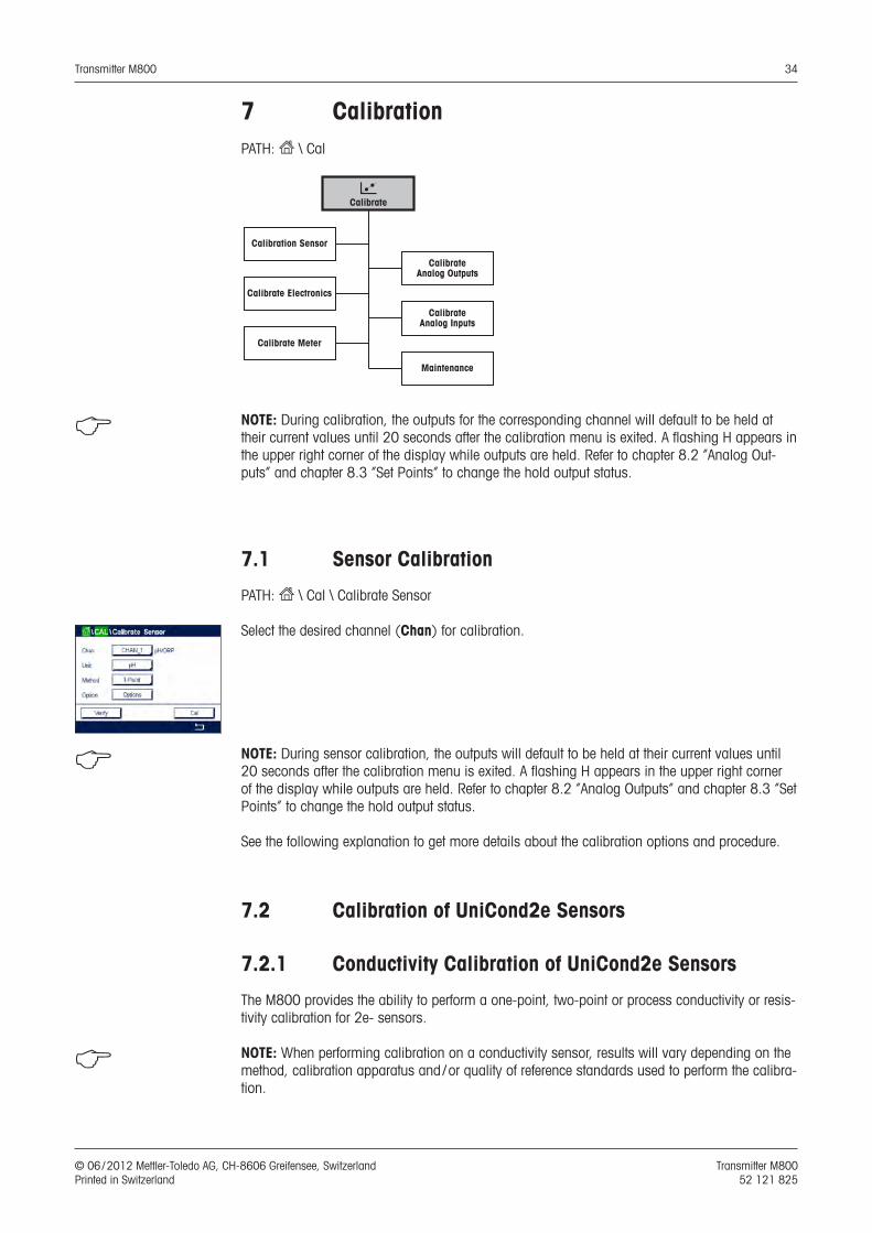
7 CalibrationPATH: H \ Cal
cCalibrate
Calibration Sensor
Calibrate Electronics
Calibrate Meter
Calibrate Analog Outputs
CalibrateAnalog Inputs
Maintenance
h NOTE: During calibration, the outputs for the corresponding channel will default to be held at their current values until 20 seconds after the calibration menu is exited. A flashing H appears in the upper right corner of the display while outputs are held. Refer to chapter 8.2 “Analog Out-puts” and chapter 8.3 “Set Points” to change the hold output status.
7.1 Sensor Calibration
PATH: H \ Cal \ Calibrate Sensor
Select the desired channel (Chan) for calibration.
h NOTE: During sensor calibration, the outputs will default to be held at their current values until 20 seconds after the calibration menu is exited. A flashing H appears in the upper right corner of the display while outputs are held. Refer to chapter 8.2 “Analog Outputs” and chapter 8.3 “Set Points” to change the hold output status.
See the following explanation to get more details about the calibration options and procedure.
7.2 Calibration of UniCond2e Sensors
7.2.1 Conductivity Calibration of UniCond2e Sensors
The M800 provides the ability to perform a one-point, two-point or process conductivity or resis-tivity calibration for 2e- sensors.
h NOTE: When performing calibration on a conductivity sensor, results will vary depending on the method, calibration apparatus and / or quality of reference standards used to perform the calibra-tion.

Transmitter M800 35
© 06 / 2012 Mettler-Toledo AG, CH-8606 Greifensee, Switzerland Transmitter M800 Printed in Switzerland 52 121 825
h NOTE: For measuring tasks the temperature compensation for the application as defined through the parameter settings for conductivity will be considered and not the temperature com-pensation selected through the calibration procedure (see also chapter 8.1.4.1 “Conductivity Settings”; PATH: H \ CONFIG \ Meas \ Parameter Setting).
Enter the menu Calibrate Sensor (see chapter 7.1 “Sensor Calibration”; PATH: H \ Cal \ Calibrate Sensor) and choose the desired channel for calibration.
The following menus can be called up:
Unit: Choose between the units for conductivity (S/cm) and resistivity (Ω-cm). Method: Select the desired calibration procedure. Available are 1-point, 2-point or process
calibration.Options: The desired compensation mode for the calibration process can be selected. Choices are “None”, ”Standard”, “Light 84”, “Std 75 °C”, ”Linear 25°C”, ”Linear
20°C”, “Glycol.5”, “Glycol1”, “Cation”, “Alcohol” and “Ammonia”. None does not make any compensation of the measured conductivity value. The un-
compensated value will be displayed and proceeded. Standard compensation includes compensation for non-linear high purity effects as
well as conventional neutral salt impurities and conforms to ASTM standards D1125 and D5391.
Light 84 compensation matches the high purity water research results of Dr. T.S. Light published in 1984. Use only if your institution has standardized on that work.
Std 75 °C compensation is the Standard compensation algorithm referenced to 75 °C. This compensation may be preferred when measuring Ultrapure Water at an elevated temperature (Resistivity of ultrapure water compensated to 75 °C is 2.4818 Mohm-cm.)
Linear 25 °C compensation adjusts the reading by a coefficient or factor expressed as %/°C (deviation from 25 °C). Use only if the solution has a well-characterized linear temperature coefficient. The factory default setting is 2.0% /°C.
Linear 20 °C compensation adjusts the reading by a coefficient or factor expressed as %/°C (deviation from 20 °C). Use only if the solution has a well-characterized linear temperature coefficient. The factory default setting is 2.0% /°C.
Glycol.5 compensation matches the temperature characteristics of 50% ethylene gly-col in water. Compensated measurements using this solution may go above 18 Mohm-cm.
Glycol1 compensation matches the temperature characteristics of 100% ethylene gly-col. Compensated measurements may go well above 18 Mohm-cm.
Cation compensation is used in power industry applications measuring the sample af-ter a cation exchanger. It takes into account the effects of temperature on the dissocia-tion of pure water in the presence of acids.
Alcohol compensation provides for the temperature characteristics of a 75% solution of isopropyl alcohol in pure water. Compensated measurements using this solution may go above 18 Mohm-cm.
Ammonia compensation is used in power industry applications for specific conductivi-ty measured on samples using ammonia and/or ETA (ethanolamine) water treatment. It takes into account the effects of temperature on the dissociation of pure water in the presence of these bases.
h NOTE: If compensation mode ”Linear 25 °C” or ”Linear 20 °C” has been chosen, the coefficient for the adjustment of the reading can be modified. In this case an additional input field will be displayed.
The changes are valid until the calibration mode has been escaped. After the values defined in the configuration menu are valid again.
Transmitter M800 36
© 06 / 2012 Mettler-Toledo AG, CH-8606 Greifensee, Switzerland Transmitter M800 Printed in Switzerland 52 121 825
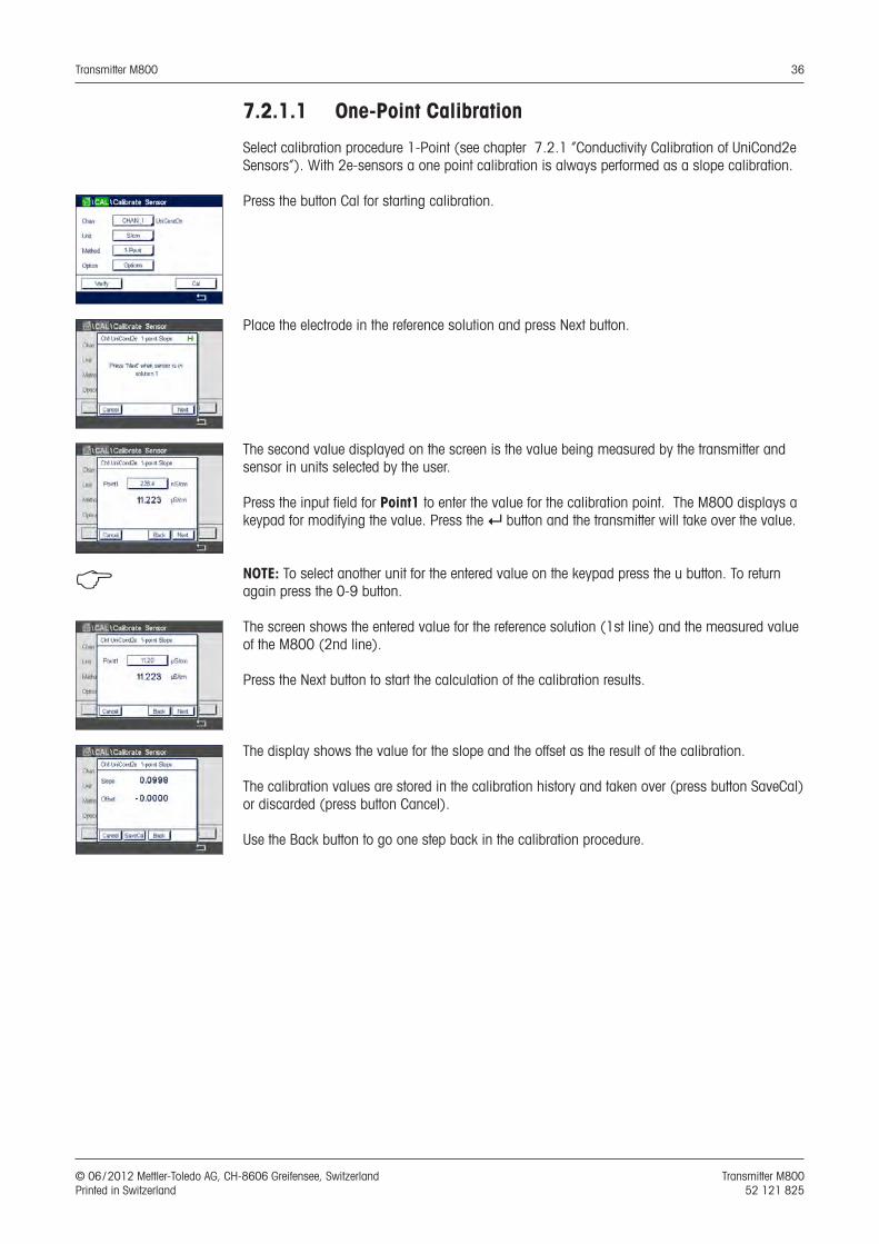
7.2.1.1 One-Point Calibration
Select calibration procedure 1-Point (see chapter 7.2.1 “Conductivity Calibration of UniCond2e Sensors”). With 2e-sensors a one point calibration is always performed as a slope calibration.
Press the button Cal for starting calibration.
Place the electrode in the reference solution and press Next button.
The second value displayed on the screen is the value being measured by the transmitter and sensor in units selected by the user.
Press the input field for Point1 to enter the value for the calibration point. The M800 displays a keypad for modifying the value. Press the e button and the transmitter will take over the value.
h NOTE: To select another unit for the entered value on the keypad press the u button. To return again press the 0-9 button.
The screen shows the entered value for the reference solution (1st line) and the measured value of the M800 (2nd line).
Press the Next button to start the calculation of the calibration results.
The display shows the value for the slope and the offset as the result of the calibration.
The calibration values are stored in the calibration history and taken over (press button SaveCal) or discarded (press button Cancel).
Use the Back button to go one step back in the calibration procedure.
Transmitter M800 37
© 06 / 2012 Mettler-Toledo AG, CH-8606 Greifensee, Switzerland Transmitter M800 Printed in Switzerland 52 121 825
If ”SaveCal” is chosen, the message ”Calibration Saved Successfully!” is displayed. In either case you will see the message ”Please re-install sensor”. After pressing the Done button the M800 returns to the calibration menu for the sensor.
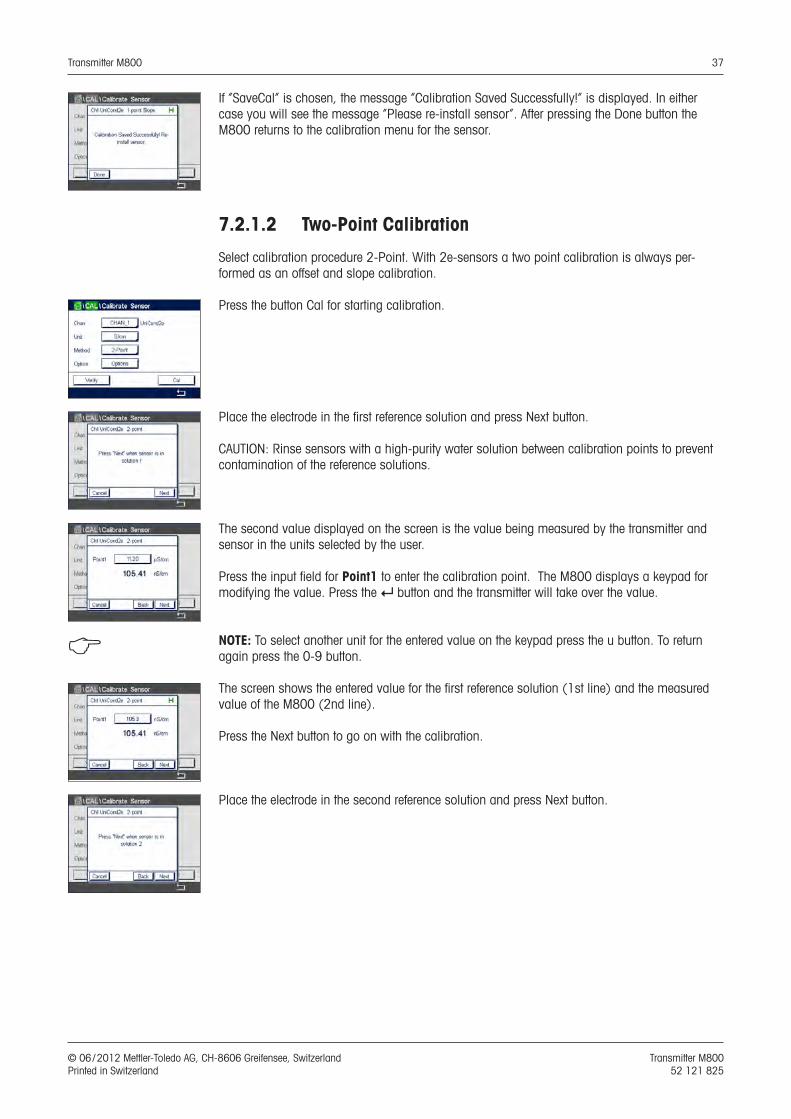
7.2.1.2 Two-Point Calibration
Select calibration procedure 2-Point. With 2e-sensors a two point calibration is always per-formed as an offset and slope calibration.
Press the button Cal for starting calibration.
Place the electrode in the first reference solution and press Next button.
CAUTION: Rinse sensors with a high-purity water solution between calibration points to prevent contamination of the reference solutions.
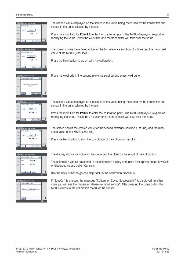
The second value displayed on the screen is the value being measured by the transmitter and sensor in the units selected by the user.
Press the input field for Point1 to enter the calibration point. The M800 displays a keypad for modifying the value. Press the e button and the transmitter will take over the value.
h NOTE: To select another unit for the entered value on the keypad press the u button. To return again press the 0-9 button.
The screen shows the entered value for the first reference solution (1st line) and the measured value of the M800 (2nd line).
Press the Next button to go on with the calibration.
Place the electrode in the second reference solution and press Next button.
Transmitter M800 38
© 06 / 2012 Mettler-Toledo AG, CH-8606 Greifensee, Switzerland Transmitter M800 Printed in Switzerland 52 121 825
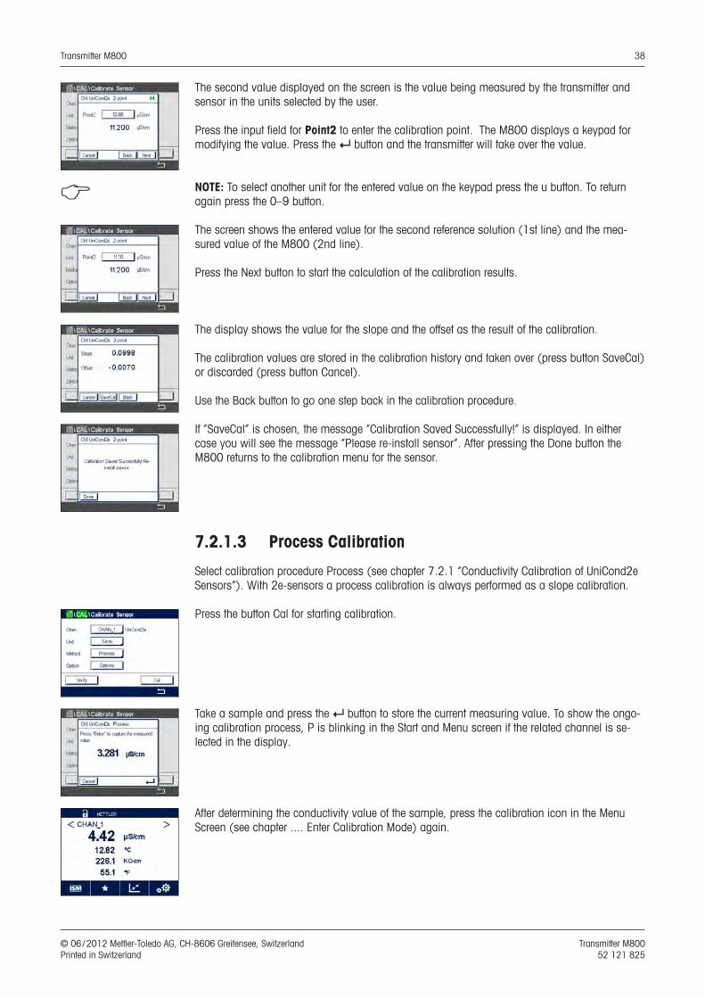
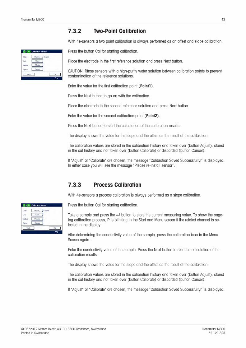
The second value displayed on the screen is the value being measured by the transmitter and sensor in the units selected by the user.
Press the input field for Point2 to enter the calibration point. The M800 displays a keypad for modifying the value. Press the e button and the transmitter will take over the value.
h NOTE: To select another unit for the entered value on the keypad press the u button. To return again press the 0–9 button.
The screen shows the entered value for the second reference solution (1st line) and the mea-sured value of the M800 (2nd line).
Press the Next button to start the calculation of the calibration results.
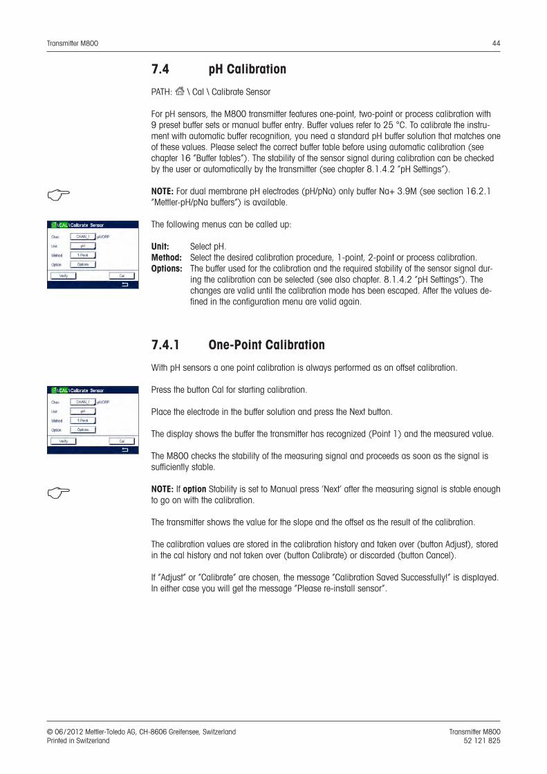
The display shows the value for the slope and the offset as the result of the calibration.
The calibration values are stored in the calibration history and taken over (press button SaveCal) or discarded (press button Cancel).
Use the Back button to go one step back in the calibration procedure.
If ”SaveCal” is chosen, the message ”Calibration Saved Successfully!” is displayed. In either case you will see the message ”Please re-install sensor”. After pressing the Done button the M800 returns to the calibration menu for the sensor.
7.2.1.3 Process Calibration
Select calibration procedure Process (see chapter 7.2.1 “Conductivity Calibration of UniCond2e Sensors”). With 2e-sensors a process calibration is always performed as a slope calibration.
Press the button Cal for starting calibration.
Take a sample and press the e button to store the current measuring value. To show the ongo-ing calibration process, P is blinking in the Start and Menu screen if the related channel is se-lected in the display.
After determining the conductivity value of the sample, press the calibration icon in the Menu Screen (see chapter .... Enter Calibration Mode) again.
Transmitter M800 39
© 06 / 2012 Mettler-Toledo AG, CH-8606 Greifensee, Switzerland Transmitter M800 Printed in Switzerland 52 121 825
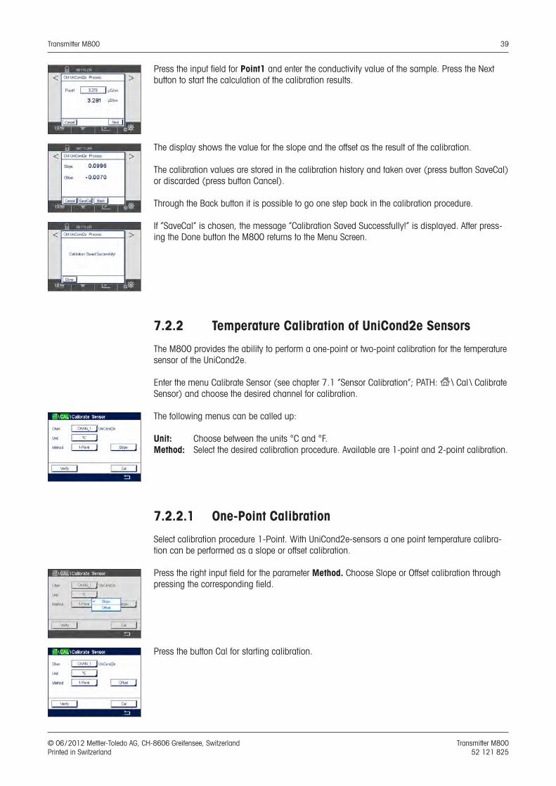
Press the input field for Point1 and enter the conductivity value of the sample. Press the Next button to start the calculation of the calibration results.
The display shows the value for the slope and the offset as the result of the calibration.
The calibration values are stored in the calibration history and taken over (press button SaveCal) or discarded (press button Cancel).
Through the Back button it is possible to go one step back in the calibration procedure.
If ”SaveCal” is chosen, the message ”Calibration Saved Successfully!” is displayed. After press-ing the Done button the M800 returns to the Menu Screen.
7.2.2 Temperature Calibration of UniCond2e Sensors
The M800 provides the ability to perform a one-point or two-point calibration for the temperature sensor of the UniCond2e.
Enter the menu Calibrate Sensor (see chapter 7.1 “Sensor Calibration”; PATH: H \ Cal \ Calibrate Sensor) and choose the desired channel for calibration.
The following menus can be called up:
Unit: Choose between the units °C and °F. Method: Select the desired calibration procedure. Available are 1-point and 2-point calibration.
7.2.2.1 One-Point Calibration
Select calibration procedure 1-Point. With UniCond2e-sensors a one point temperature calibra-tion can be performed as a slope or offset calibration.
Press the right input field for the parameter Method. Choose Slope or Offset calibration through pressing the corresponding field.
Press the button Cal for starting calibration.
Transmitter M800 40
© 06 / 2012 Mettler-Toledo AG, CH-8606 Greifensee, Switzerland Transmitter M800 Printed in Switzerland 52 121 825
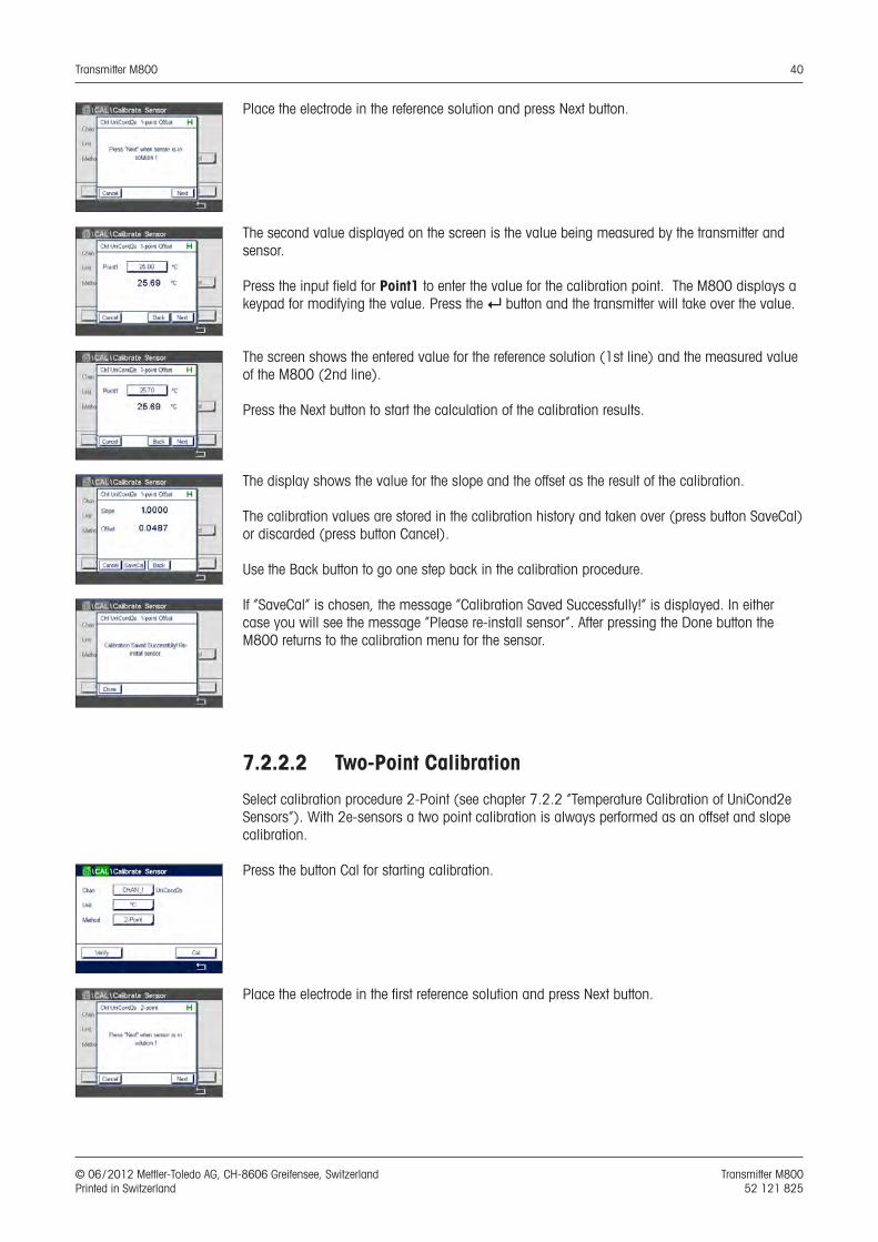
Place the electrode in the reference solution and press Next button.
The second value displayed on the screen is the value being measured by the transmitter and sensor.
Press the input field for Point1 to enter the value for the calibration point. The M800 displays a keypad for modifying the value. Press the e button and the transmitter will take over the value.
The screen shows the entered value for the reference solution (1st line) and the measured value of the M800 (2nd line).
Press the Next button to start the calculation of the calibration results.
The display shows the value for the slope and the offset as the result of the calibration.
The calibration values are stored in the calibration history and taken over (press button SaveCal) or discarded (press button Cancel).
Use the Back button to go one step back in the calibration procedure.
If ”SaveCal” is chosen, the message ”Calibration Saved Successfully!” is displayed. In either case you will see the message ”Please re-install sensor”. After pressing the Done button the M800 returns to the calibration menu for the sensor.
7.2.2.2 Two-Point Calibration
Select calibration procedure 2-Point (see chapter 7.2.2 “Temperature Calibration of UniCond2e Sensors”). With 2e-sensors a two point calibration is always performed as an offset and slope calibration.
Press the button Cal for starting calibration.
Place the electrode in the first reference solution and press Next button.
Transmitter M800 41
© 06 / 2012 Mettler-Toledo AG, CH-8606 Greifensee, Switzerland Transmitter M800 Printed in Switzerland 52 121 825
The second value displayed on the screen is the value being measured by the transmitter and sensor in the units selected by the user.
Press the input field for Point1 to enter the calibration point. The M800 displays a keypad for modifying the value. Press the e button and the transmitter will take over the value.
The screen shows the entered value for the first reference solution (1st line) and the measured value of the M800 (2nd line).
Press the Next button to go on with the calibration.
Place the electrode in the second reference solution and press Next button.
The second value displayed on the screen is the value being measured by the transmitter and sensor in the units selected by the user.
Press the input field for Point2 to enter the calibration point. The M800 displays a keypad for modifying the value. Press the e button and the transmitter will take over the value.
The screen shows the entered value for the second reference solution (1st line) and the mea-sured value of the M800 (2nd line).
Press the Next button to start the calculation of the calibration results.
The display shows the value for the slope and the offset as the result of the calibration.
The calibration values are stored in the calibration history and taken over (press button SaveCal) or discarded (press button Cancel).
Use the Back button to go one step back in the calibration procedure.
If ”SaveCal” is chosen, the message ”Calibration Saved Successfully!” is displayed. In either case you will see the message ”Please re-install sensor”. After pressing the Done button the M800 returns to the calibration menu for the sensor.

Transmitter M800 42
© 06 / 2012 Mettler-Toledo AG, CH-8606 Greifensee, Switzerland Transmitter M800 Printed in Switzerland 52 121 825
7.3 Calibration of Cond4e Sensors
PATH: H \ Cal \ Calibrate Sensor
The M800 provides the ability to perform a one-point, two-point or process conductivity or resis-tivity calibration for 4e sensors.
h NOTE: When performing calibration on a conductivity sensor, results will vary depending on the method, calibration apparatus and / or quality of reference standards used to perform the calibra-tion.
h NOTE: For measuring tasks the temperature compensation for the application as defined through the parameter settings for conductivity will be considered and not the temperature com-pensation selected through the calibration procedure (see also chapter 8.1.4.1 “Conductivity Settings”).
The following menus can be called up:
Unit: Between the units for conductivity and resistivity can be chosen. Method: Select the desired calibration procedure, 1-point, 2-point or process calibration.Options: Select the desired temperature compensation mode for the calibration process.
h NOTE: If compensation mode ”Linear 25 °C” or ”Linear 20 °C” has been chosen, the coefficient for the adjustment of the reading can be modified.
The changes are valid until the calibration mode has been exited. After the values defined in the configuration menu are valid again.
7.3.1 One-Point Calibration
With 4e-sensors a one point calibration is always performed as a slope calibration.
Press the button Cal for starting calibration.
Place the electrode in the reference solution and press Next button.
Enter the value for the calibration point (Point1).
Press the Next button to start the calculation of the calibration results.
The display shows the value for the slope and the offset as the result of the calibration.
The calibration values are stored in the calibration history and taken over (button Adjust), stored in the cal history and not taken over (button Calibrate) or discarded (button Cancel).
If ”Adjust” or ”Calibrate” are chosen, the message ”Calibration Saved Successfully!” is displayed. In either case you will see the message ”Please re-install sensor”.
Transmitter M800 43
© 06 / 2012 Mettler-Toledo AG, CH-8606 Greifensee, Switzerland Transmitter M800 Printed in Switzerland 52 121 825
7.3.2 Two-Point Calibration
With 4e-sensors a two point calibration is always performed as an offset and slope calibration.
Press the button Cal for starting calibration.
Place the electrode in the first reference solution and press Next button.
CAUTION: Rinse sensors with a high-purity water solution between calibration points to prevent contamination of the reference solutions.
Enter the value for the first calibration point (Point1).
Press the Next button to go on with the calibration.
Place the electrode in the second reference solution and press Next button.
Enter the value for the second calibration point (Point2).
Press the Next button to start the calculation of the calibration results.
The display shows the value for the slope and the offset as the result of the calibration.
The calibration values are stored in the calibration history and taken over (button Adjust), stored in the cal history and not taken over (button Calibrate) or discarded (button Cancel).
If ”Adjust” or ”Calibrate” are chosen, the message ”Calibration Saved Successfully!” is displayed. In either case you will see the message ”Please re-install sensor”.
7.3.3 Process Calibration
With 4e-sensors a process calibration is always performed as a slope calibration.
Press the button Cal for starting calibration.
Take a sample and press the e button to store the current measuring value. To show the ongo-ing calibration process, P is blinking in the Start and Menu screen if the related channel is se-lected in the display.
After determining the conductivity value of the sample, press the calibration icon in the Menu Screen again.
Enter the conductivity value of the sample. Press the Next button to start the calculation of the calibration results.
The display shows the value for the slope and the offset as the result of the calibration.
The calibration values are stored in the calibration history and taken over (button Adjust), stored in the cal history and not taken over (button Calibrate) or discarded (button Cancel).
If ”Adjust” or ”Calibrate” are chosen, the message ”Calibration Saved Successfully!” is displayed.
Transmitter M800 44
© 06 / 2012 Mettler-Toledo AG, CH-8606 Greifensee, Switzerland Transmitter M800 Printed in Switzerland 52 121 825
7.4 pH Calibration
PATH: H \ Cal \ Calibrate Sensor
For pH sensors, the M800 transmitter features one-point, two-point or process calibration with 9 preset buffer sets or manual buffer entry. Buffer values refer to 25 °C. To calibrate the instru-ment with automatic buffer recognition, you need a standard pH buffer solution that matches one of these values. Please select the correct buffer table before using automatic calibration (see chapter 16 “Buffer tables”). The stability of the sensor signal during calibration can be checked by the user or automatically by the transmitter (see chapter 8.1.4.2 “pH Settings”).
h NOTE: For dual membrane pH electrodes (pH/pNa) only buffer Na+ 3.9M (see section 16.2.1 “Mettler-pH/pNa buffers”) is available.
The following menus can be called up:
Unit: Select pH.Method: Select the desired calibration procedure, 1-point, 2-point or process calibration.Options: The buffer used for the calibration and the required stability of the sensor signal dur-
ing the calibration can be selected (see also chapter. 8.1.4.2 ”pH Settings”). The changes are valid until the calibration mode has been escaped. After the values de-fined in the configuration menu are valid again.
7.4.1 One-Point Calibration
With pH sensors a one point calibration is always performed as an offset calibration.
Press the button Cal for starting calibration.
Place the electrode in the buffer solution and press the Next button.
The display shows the buffer the transmitter has recognized (Point 1) and the measured value.
The M800 checks the stability of the measuring signal and proceeds as soon as the signal is sufficiently stable.
h NOTE: If option Stability is set to Manual press ‘Next’ after the measuring signal is stable enough to go on with the calibration.
The transmitter shows the value for the slope and the offset as the result of the calibration.
The calibration values are stored in the calibration history and taken over (button Adjust), stored in the cal history and not taken over (button Calibrate) or discarded (button Cancel).
If ”Adjust” or ”Calibrate” are chosen, the message ”Calibration Saved Successfully!” is displayed. In either case you will get the message ”Please re-install sensor”.
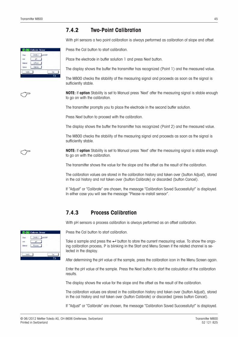
Transmitter M800 45
© 06 / 2012 Mettler-Toledo AG, CH-8606 Greifensee, Switzerland Transmitter M800 Printed in Switzerland 52 121 825
7.4.2 Two-Point Calibration
With pH sensors a two point calibration is always performed as calibration of slope and offset.
Press the Cal button to start calibration.
Place the electrode in buffer solution 1 and press Next button.
The display shows the buffer the transmitter has recognized (Point 1) and the measured value.
The M800 checks the stability of the measuring signal and proceeds as soon as the signal is sufficiently stable.
h NOTE: If option Stability is set to Manual press ‘Next’ after the measuring signal is stable enough to go on with the calibration.
The transmitter prompts you to place the electrode in the second buffer solution.
Press Next button to proceed with the calibration.
The display shows the buffer the transmitter has recognized (Point 2) and the measured value.
The M800 checks the stability of the measuring signal and proceeds as soon as the signal is sufficiently stable.
h NOTE: If option Stability is set to Manual press ‘Next’ after the measuring signal is stable enough to go on with the calibration.
The transmitter shows the value for the slope and the offset as the result of the calibration.
The calibration values are stored in the calibration history and taken over (button Adjust), stored in the cal history and not taken over (button Calibrate) or discarded (button Cancel).
If ”Adjust” or ”Calibrate” are chosen, the message ”Calibration Saved Successfully!” is displayed. In either case you will see the message ”Please re-install sensor”.
7.4.3 Process Calibration
With pH sensors a process calibration is always performed as an offset calibration.
Press the Cal button to start calibration.
Take a sample and press the e button to store the current measuring value. To show the ongo-ing calibration process, P is blinking in the Start and Menu Screen if the related channel is se-lected in the display.
After determining the pH value of the sample, press the calibration icon in the Menu Screen again.
Enter the pH value of the sample. Press the Next button to start the calculation of the calibration results.
The display shows the value for the slope and the offset as the result of the calibration.
The calibration values are stored in the calibration history and taken over (button Adjust), stored in the cal history and not taken over (button Calibrate) or discarded (press button Cancel).
If ”Adjust” or ”Calibrate” are chosen, the message ”Calibration Saved Successfully!” is displayed.
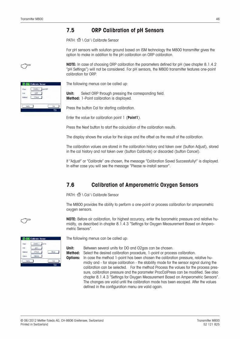
Transmitter M800 46
© 06 / 2012 Mettler-Toledo AG, CH-8606 Greifensee, Switzerland Transmitter M800 Printed in Switzerland 52 121 825
7.5 ORP Calibration of pH Sensors
PATH: H \ Cal \ Calibrate Sensor
For pH sensors with solution ground based on ISM technology the M800 transmitter gives the option to make in addition to the pH calibration an ORP calibration.
h NOTE: In case of choosing ORP calibration the parameters defined for pH (see chapter 8.1.4.2 “pH Settings”) will not be considered. For pH sensors, the M800 transmitter features one-point calibration for ORP.
The following menus can be called up:
Unit: Select ORP through pressing the corresponding field.Method: 1-Point calibration is displayed.
Press the button Cal for starting calibration.
Enter the value for calibration point 1 (Point1).
Press the Next button to start the calculation of the calibration results.
The display shows the value for the slope and the offset as the result of the calibration.
The calibration values are stored in the calibration history and taken over (button Adjust), stored in the cal history and not taken over (button Calibrate) or discarded (button Cancel).
If ”Adjust” or ”Calibrate” are chosen, the message ”Calibration Saved Successfully!” is displayed. In either case you will see the message ”Please re-install sensor”.
7.6 Calibration of Amperometric Oxygen Sensors
PATH: H \ Cal \ Calibrate Sensor
The M800 provides the ability to perform a one-point or process calibration for amperometric oxygen sensors.
h NOTE: Before air calibration, for highest accuracy, enter the barometric pressure and relative hu-midity, as described in chapter 8.1.4.3 “Settings for Oxygen Measurement Based on Ampero-metric Sensors”.
The following menus can be called up:
Unit: Between several units for DO and O2gas can be chosen. Method: Select the desired calibration procedure, 1-point or process calibration. Options: In case the method 1-point has been chosen the calibration pressure, relative hu-
midiy and - for slope calibration - the stability mode for the sensor signal during the calibration can be selected. For the method Process the values for the process pres-sure, calibration pressure and the parameter ProcCalPress can be modified. See also chapter 8.1.4.3 “Settings for Oxygen Measurement Based on Amperometric Sensors”. The changes are valid until the calibration mode has been escaped. After the values defined in the configuration menu are valid again.
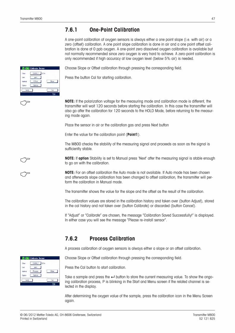
Transmitter M800 47
© 06 / 2012 Mettler-Toledo AG, CH-8606 Greifensee, Switzerland Transmitter M800 Printed in Switzerland 52 121 825
7.6.1 One-Point Calibration
A one-point calibration of oxygen sensors is always either a one point slope (i.e. with air) or a zero (offset) calibration. A one point slope calibration is done in air and a one point offset cali-bration is done at 0 ppb oxygen. A one-point zero dissolved oxygen calibration is available but not normally recommended since zero oxygen is very hard to achieve. A zero-point calibration is only recommended if high accuracy at low oxygen level (below 5% air) is needed.
Choose Slope or Offset calibration through pressing the corresponding field.
Press the button Cal for starting calibration.
h NOTE: If the polarization voltage for the measuring mode and calibration mode is different, the transmitter will wait 120 seconds before starting the calibration. In this case the transmitter will also go after the calibration for 120 seconds to the HOLD Mode, before returning to the measur-ing mode again.
Place the sensor in air or the calibration gas and press Next button
Enter the value for the calibration point (Point1).
The M800 checks the stability of the measuring signal and proceeds as soon as the signal is sufficiently stable.
h NOTE: If option Stability is set to Manual press ‘Next’ after the measuring signal is stable enough to go on with the calibration.
h NOTE: For an offset calibration the Auto mode is not available. If Auto mode has been chosen and afterwards slope calibration has been changed to offset calibration, the transmitter will per-form the calibration in Manual mode.
The transmitter shows the value for the slope and the offset as the result of the calibration.
The calibration values are stored in the calibration history and taken over (button Adjust), stored in the cal history and not taken over (button Calibrate) or discarded (button Cancel).
If ”Adjust” or ”Calibrate” are chosen, the message ”Calibration Saved Successfully!” is displayed. In either case you will see the message ”Please re-install sensor”.
7.6.2 Process Calibration
A process calibration of oxygen sensors is always either a slope or an offset calibration.
Choose Slope or Offset calibration through pressing the corresponding field.
Press the Cal button to start calibration.
Take a sample and press the e button to store the current measuring value. To show the ongo-ing calibration process, P is blinking in the Start and Menu screen if the related channel is se-lected in the display.
After determining the oxygen value of the sample, press the calibration icon in the Menu Screen again.
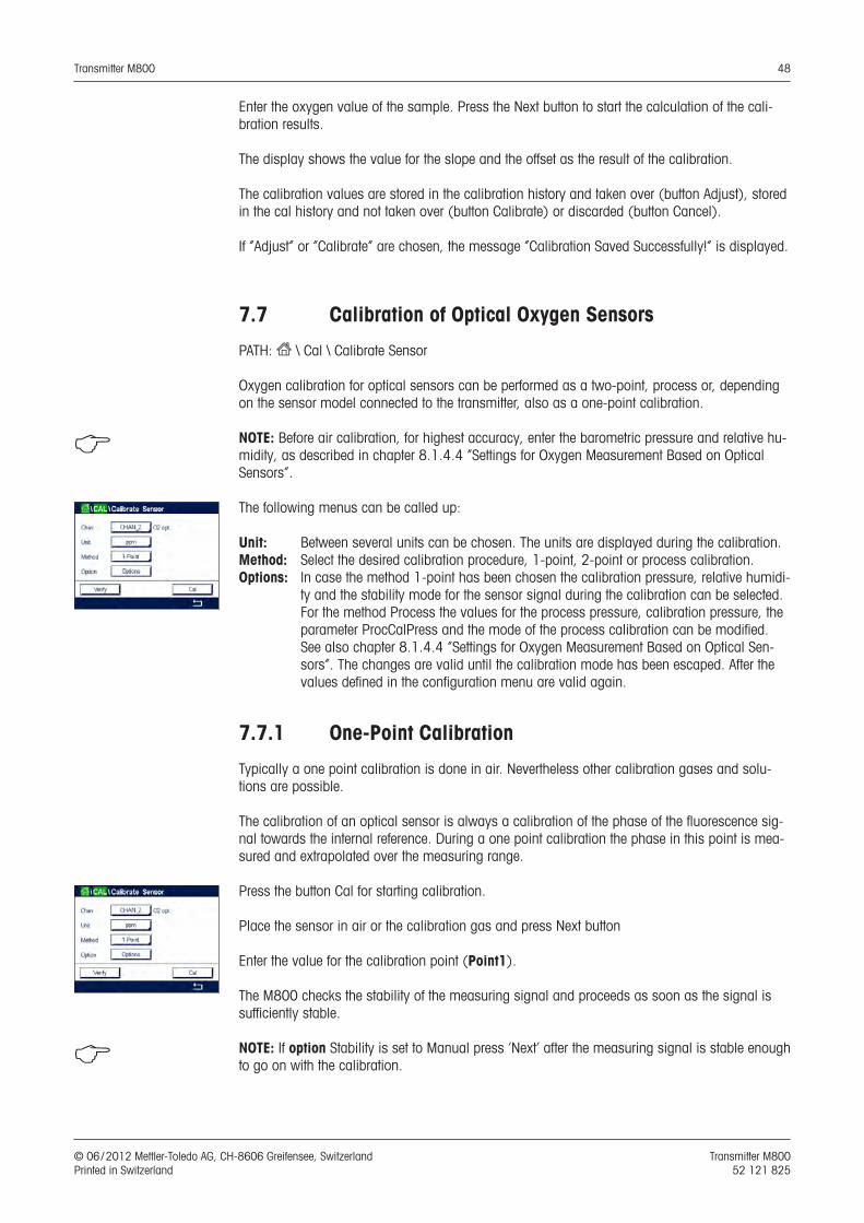
Transmitter M800 48
© 06 / 2012 Mettler-Toledo AG, CH-8606 Greifensee, Switzerland Transmitter M800 Printed in Switzerland 52 121 825
Enter the oxygen value of the sample. Press the Next button to start the calculation of the cali-bration results.
The display shows the value for the slope and the offset as the result of the calibration.
The calibration values are stored in the calibration history and taken over (button Adjust), stored in the cal history and not taken over (button Calibrate) or discarded (button Cancel).
If ”Adjust” or ”Calibrate” are chosen, the message ”Calibration Saved Successfully!” is displayed.
7.7 Calibration of Optical Oxygen Sensors
PATH: H \ Cal \ Calibrate Sensor
Oxygen calibration for optical sensors can be performed as a two-point, process or, depending on the sensor model connected to the transmitter, also as a one-point calibration.
h NOTE: Before air calibration, for highest accuracy, enter the barometric pressure and relative hu-midity, as described in chapter 8.1.4.4 “Settings for Oxygen Measurement Based on Optical Sensors”.
The following menus can be called up:
Unit: Between several units can be chosen. The units are displayed during the calibration. Method: Select the desired calibration procedure, 1-point, 2-point or process calibration. Options: In case the method 1-point has been chosen the calibration pressure, relative humidi-
ty and the stability mode for the sensor signal during the calibration can be selected. For the method Process the values for the process pressure, calibration pressure, the parameter ProcCalPress and the mode of the process calibration can be modified. See also chapter 8.1.4.4 “Settings for Oxygen Measurement Based on Optical Sen-sors”. The changes are valid until the calibration mode has been escaped. After the values defined in the configuration menu are valid again.
7.7.1 One-Point Calibration
Typically a one point calibration is done in air. Nevertheless other calibration gases and solu-tions are possible.
The calibration of an optical sensor is always a calibration of the phase of the fluorescence sig-nal towards the internal reference. During a one point calibration the phase in this point is mea-sured and extrapolated over the measuring range.
Press the button Cal for starting calibration.
Place the sensor in air or the calibration gas and press Next button
Enter the value for the calibration point (Point1).
The M800 checks the stability of the measuring signal and proceeds as soon as the signal is sufficiently stable.
h NOTE: If option Stability is set to Manual press ‘Next’ after the measuring signal is stable enough to go on with the calibration.
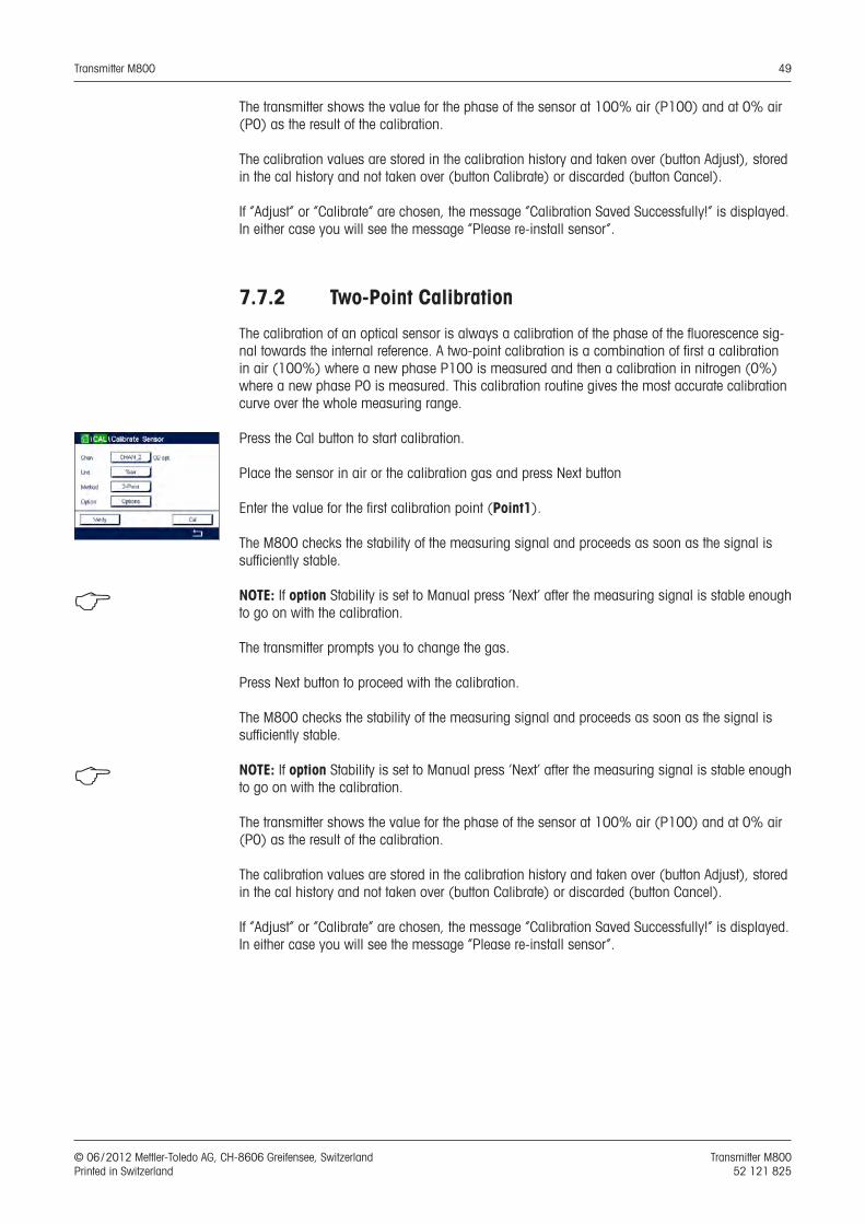
Transmitter M800 49
© 06 / 2012 Mettler-Toledo AG, CH-8606 Greifensee, Switzerland Transmitter M800 Printed in Switzerland 52 121 825
The transmitter shows the value for the phase of the sensor at 100% air (P100) and at 0% air (P0) as the result of the calibration.
The calibration values are stored in the calibration history and taken over (button Adjust), stored in the cal history and not taken over (button Calibrate) or discarded (button Cancel).
If ”Adjust” or ”Calibrate” are chosen, the message ”Calibration Saved Successfully!” is displayed. In either case you will see the message ”Please re-install sensor”.
7.7.2 Two-Point Calibration
The calibration of an optical sensor is always a calibration of the phase of the fluorescence sig-nal towards the internal reference. A two-point calibration is a combination of first a calibration in air (100%) where a new phase P100 is measured and then a calibration in nitrogen (0%) where a new phase P0 is measured. This calibration routine gives the most accurate calibration curve over the whole measuring range.
Press the Cal button to start calibration.
Place the sensor in air or the calibration gas and press Next button
Enter the value for the first calibration point (Point1).
The M800 checks the stability of the measuring signal and proceeds as soon as the signal is sufficiently stable.
h NOTE: If option Stability is set to Manual press ‘Next’ after the measuring signal is stable enough to go on with the calibration.
The transmitter prompts you to change the gas.
Press Next button to proceed with the calibration.
The M800 checks the stability of the measuring signal and proceeds as soon as the signal is sufficiently stable.
h NOTE: If option Stability is set to Manual press ‘Next’ after the measuring signal is stable enough to go on with the calibration.
The transmitter shows the value for the phase of the sensor at 100% air (P100) and at 0% air (P0) as the result of the calibration.
The calibration values are stored in the calibration history and taken over (button Adjust), stored in the cal history and not taken over (button Calibrate) or discarded (button Cancel).
If ”Adjust” or ”Calibrate” are chosen, the message ”Calibration Saved Successfully!” is displayed. In either case you will see the message ”Please re-install sensor”.
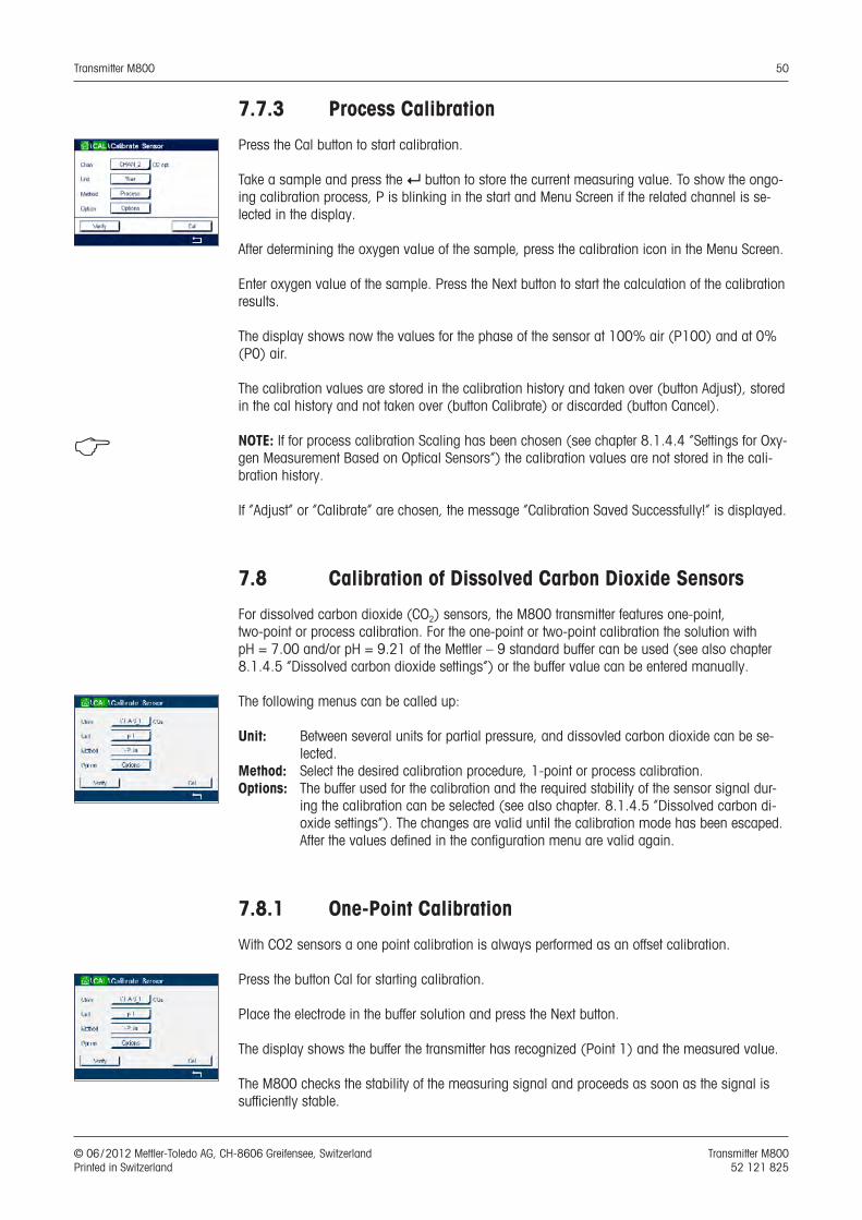
Transmitter M800 50
© 06 / 2012 Mettler-Toledo AG, CH-8606 Greifensee, Switzerland Transmitter M800 Printed in Switzerland 52 121 825
7.7.3 Process Calibration
Press the Cal button to start calibration.
Take a sample and press the e button to store the current measuring value. To show the ongo-ing calibration process, P is blinking in the start and Menu Screen if the related channel is se-lected in the display.
After determining the oxygen value of the sample, press the calibration icon in the Menu Screen.
Enter oxygen value of the sample. Press the Next button to start the calculation of the calibration results.
The display shows now the values for the phase of the sensor at 100% air (P100) and at 0% (P0) air.
The calibration values are stored in the calibration history and taken over (button Adjust), stored in the cal history and not taken over (button Calibrate) or discarded (button Cancel).
h NOTE: If for process calibration Scaling has been chosen (see chapter 8.1.4.4 “Settings for Oxy-gen Measurement Based on Optical Sensors”) the calibration values are not stored in the cali-bration history.
If ”Adjust” or ”Calibrate” are chosen, the message ”Calibration Saved Successfully!” is displayed.
7.8 Calibration of Dissolved Carbon Dioxide Sensors
For dissolved carbon dioxide (CO2) sensors, the M800 transmitter features one-point, two-point or process calibration. For the one-point or two-point calibration the solution with pH = 7.00 and/or pH = 9.21 of the Mettler – 9 standard buffer can be used (see also chapter 8.1.4.5 “Dissolved carbon dioxide settings”) or the buffer value can be entered manually.
The following menus can be called up:
Unit: Between several units for partial pressure, and dissovled carbon dioxide can be se-lected.
Method: Select the desired calibration procedure, 1-point or process calibration. Options: The buffer used for the calibration and the required stability of the sensor signal dur-
ing the calibration can be selected (see also chapter. 8.1.4.5 ”Dissolved carbon di-oxide settings”). The changes are valid until the calibration mode has been escaped. After the values defined in the configuration menu are valid again.
7.8.1 One-Point Calibration
With CO2 sensors a one point calibration is always performed as an offset calibration.
Press the button Cal for starting calibration.
Place the electrode in the buffer solution and press the Next button.
The display shows the buffer the transmitter has recognized (Point 1) and the measured value.
The M800 checks the stability of the measuring signal and proceeds as soon as the signal is sufficiently stable.
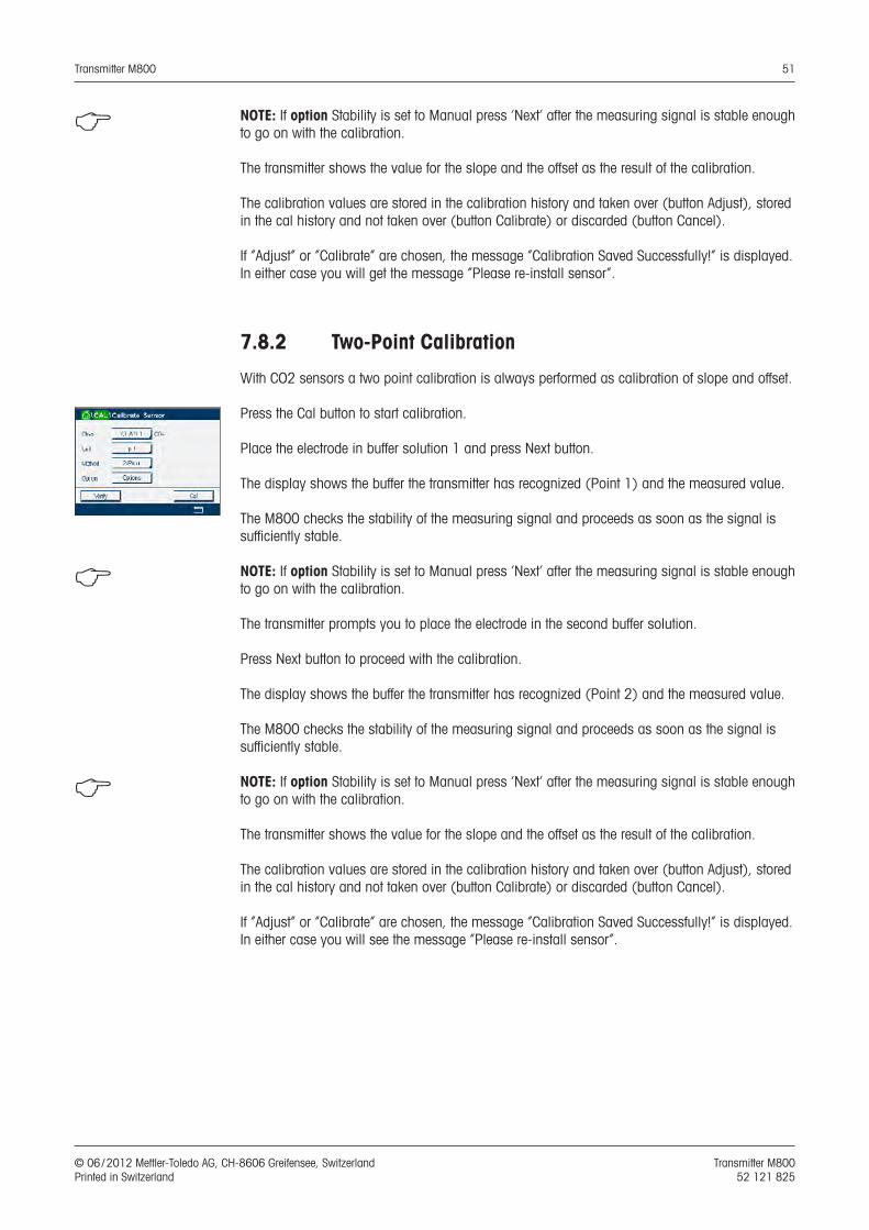
Transmitter M800 51
© 06 / 2012 Mettler-Toledo AG, CH-8606 Greifensee, Switzerland Transmitter M800 Printed in Switzerland 52 121 825
h NOTE: If option Stability is set to Manual press ‘Next’ after the measuring signal is stable enough to go on with the calibration.
The transmitter shows the value for the slope and the offset as the result of the calibration.
The calibration values are stored in the calibration history and taken over (button Adjust), stored in the cal history and not taken over (button Calibrate) or discarded (button Cancel).
If ”Adjust” or ”Calibrate” are chosen, the message ”Calibration Saved Successfully!” is displayed. In either case you will get the message ”Please re-install sensor”.
7.8.2 Two-Point Calibration
With CO2 sensors a two point calibration is always performed as calibration of slope and offset.
Press the Cal button to start calibration.
Place the electrode in buffer solution 1 and press Next button.
The display shows the buffer the transmitter has recognized (Point 1) and the measured value.
The M800 checks the stability of the measuring signal and proceeds as soon as the signal is sufficiently stable.
h NOTE: If option Stability is set to Manual press ‘Next’ after the measuring signal is stable enough to go on with the calibration.
The transmitter prompts you to place the electrode in the second buffer solution.
Press Next button to proceed with the calibration.
The display shows the buffer the transmitter has recognized (Point 2) and the measured value.
The M800 checks the stability of the measuring signal and proceeds as soon as the signal is sufficiently stable.
h NOTE: If option Stability is set to Manual press ‘Next’ after the measuring signal is stable enough to go on with the calibration.
The transmitter shows the value for the slope and the offset as the result of the calibration.
The calibration values are stored in the calibration history and taken over (button Adjust), stored in the cal history and not taken over (button Calibrate) or discarded (button Cancel).
If ”Adjust” or ”Calibrate” are chosen, the message ”Calibration Saved Successfully!” is displayed. In either case you will see the message ”Please re-install sensor”.
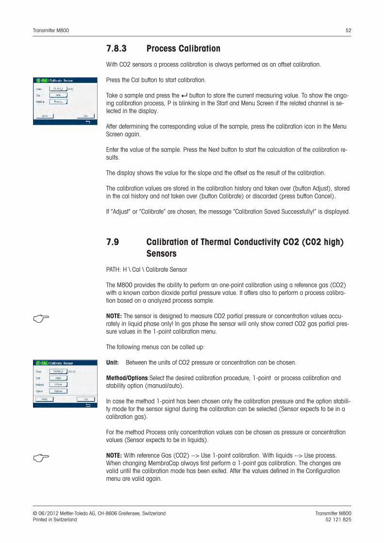
Transmitter M800 52
© 06 / 2012 Mettler-Toledo AG, CH-8606 Greifensee, Switzerland Transmitter M800 Printed in Switzerland 52 121 825
7.8.3 Process Calibration
With CO2 sensors a process calibration is always performed as an offset calibration.
Press the Cal button to start calibration.
Take a sample and press the e button to store the current measuring value. To show the ongo-ing calibration process, P is blinking in the Start and Menu Screen if the related channel is se-lected in the display.
After determining the corresponding value of the sample, press the calibration icon in the Menu Screen again.
Enter the value of the sample. Press the Next button to start the calculation of the calibration re-sults.
The display shows the value for the slope and the offset as the result of the calibration.
The calibration values are stored in the calibration history and taken over (button Adjust), stored in the cal history and not taken over (button Calibrate) or discarded (press button Cancel).
If ”Adjust” or ”Calibrate” are chosen, the message ”Calibration Saved Successfully!” is displayed.
7.9 Calibration of Thermal Conductivity CO2 (C02 high) Sensors
PATH: H \ Cal \ Calibrate Sensor
The M800 provides the ability to perform an one-point calibration using a reference gas (CO2) with a known carbon dioxide partial pressure value. It offers also to perform a process calibra-tion based on a analyzed process sample.
h NOTE: The sensor is designed to measure CO2 partial pressure or concentration values accu-rately in liquid phase only! In gas phase the sensor will only show correct CO2 gas partial pres-sure values in the 1-point calibration menu.
The following menus can be called up:
Unit: Between the units of CO2 pressure or concentration can be chosen.
Method/Options:Select the desired calibration procedure, 1-point or process calibration and stability option (manual/auto).
In case the method 1-point has been chosen only the calibration pressure and the option stabili-ty mode for the sensor signal during the calibration can be selected (Sensor expects to be in a calibration gas).
For the method Process only concentration values can be chosen as pressure or concentration values (Sensor expects to be in liquids).
h NOTE: With reference Gas (CO2) --> Use 1-point calibration. With liquids --> Use process. When changing MembraCap always first perform a 1-point gas calibration. The changes are valid until the calibration mode has been exited. After the values defined in the Configuration menu are valid again.
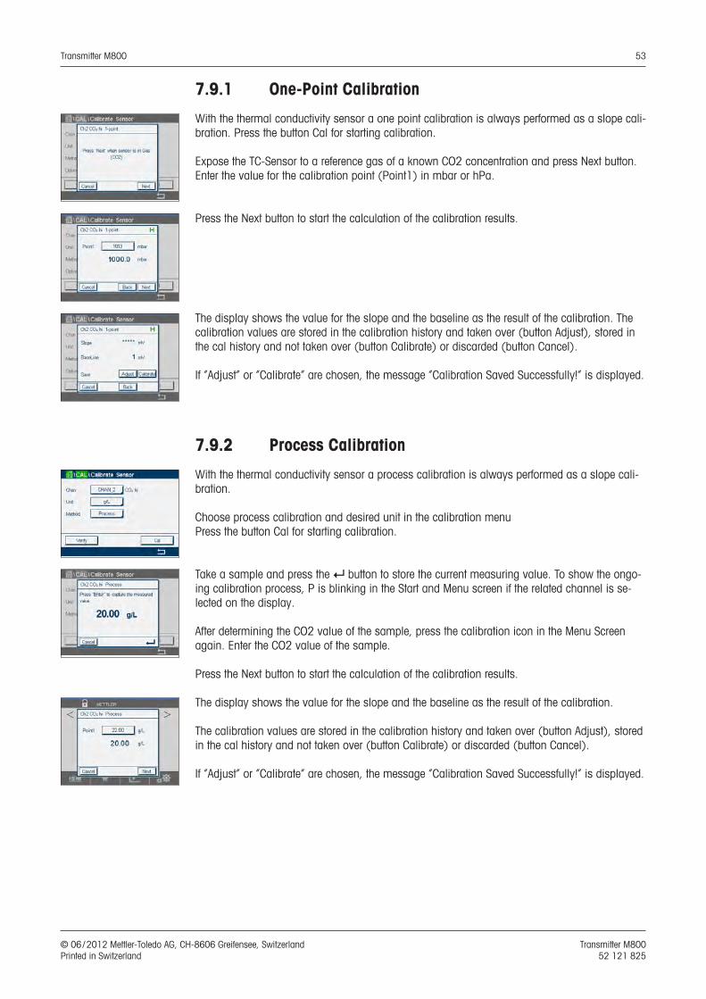
Transmitter M800 53
© 06 / 2012 Mettler-Toledo AG, CH-8606 Greifensee, Switzerland Transmitter M800 Printed in Switzerland 52 121 825
7.9.1 One-Point Calibration
With the thermal conductivity sensor a one point calibration is always performed as a slope cali-bration. Press the button Cal for starting calibration.
Expose the TC-Sensor to a reference gas of a known CO2 concentration and press Next button.Enter the value for the calibration point (Point1) in mbar or hPa.
Press the Next button to start the calculation of the calibration results.
The display shows the value for the slope and the baseline as the result of the calibration. The calibration values are stored in the calibration history and taken over (button Adjust), stored in the cal history and not taken over (button Calibrate) or discarded (button Cancel).
If ”Adjust” or ”Calibrate” are chosen, the message ”Calibration Saved Successfully!” is displayed.
7.9.2 Process Calibration
With the thermal conductivity sensor a process calibration is always performed as a slope cali-bration.
Choose process calibration and desired unit in the calibration menuPress the button Cal for starting calibration.
Take a sample and press the e button to store the current measuring value. To show the ongo-ing calibration process, P is blinking in the Start and Menu screen if the related channel is se-lected on the display.
After determining the CO2 value of the sample, press the calibration icon in the Menu Screen again. Enter the CO2 value of the sample.
Press the Next button to start the calculation of the calibration results.
The display shows the value for the slope and the baseline as the result of the calibration.
The calibration values are stored in the calibration history and taken over (button Adjust), stored in the cal history and not taken over (button Calibrate) or discarded (button Cancel).
If ”Adjust” or ”Calibrate” are chosen, the message ”Calibration Saved Successfully!” is displayed.
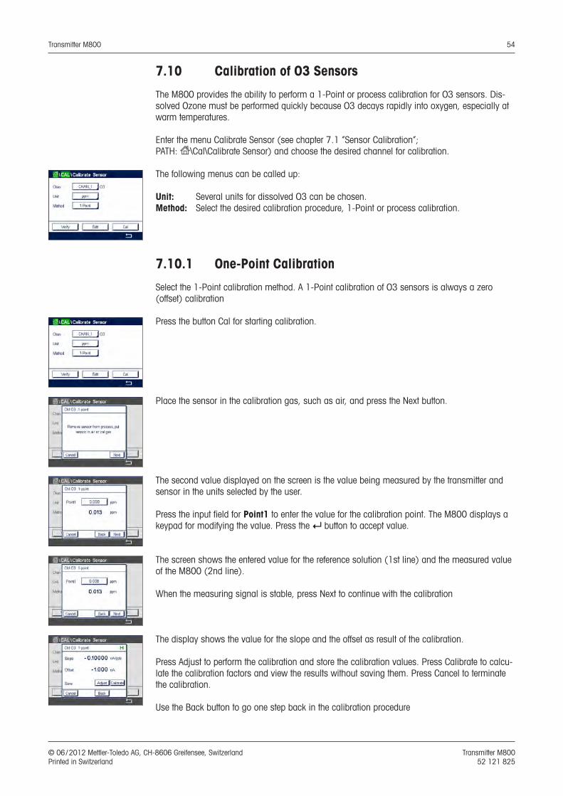
Transmitter M800 54
© 06 / 2012 Mettler-Toledo AG, CH-8606 Greifensee, Switzerland Transmitter M800 Printed in Switzerland 52 121 825
7.10 Calibration of O3 Sensors
The M800 provides the ability to perform a 1-Point or process calibration for O3 sensors. Dis-solved Ozone must be performed quickly because O3 decays rapidly into oxygen, especially at warm temperatures.
Enter the menu Calibrate Sensor (see chapter 7.1 “Sensor Calibration”; PATH: H\Cal\Calibrate Sensor) and choose the desired channel for calibration.
The following menus can be called up:
Unit: Several units for dissolved O3 can be chosen. Method: Select the desired calibration procedure, 1-Point or process calibration.
7.10.1 One-Point Calibration
Select the 1-Point calibration method. A 1-Point calibration of O3 sensors is always a zero (offset) calibration
Press the button Cal for starting calibration.
Place the sensor in the calibration gas, such as air, and press the Next button.
The second value displayed on the screen is the value being measured by the transmitter and sensor in the units selected by the user.
Press the input field for Point1 to enter the value for the calibration point. The M800 displays a keypad for modifying the value. Press the e button to accept value.
The screen shows the entered value for the reference solution (1st line) and the measured value of the M800 (2nd line).
When the measuring signal is stable, press Next to continue with the calibration
The display shows the value for the slope and the offset as result of the calibration.
Press Adjust to perform the calibration and store the calibration values. Press Calibrate to calcu-late the calibration factors and view the results without saving them. Press Cancel to terminate the calibration.
Use the Back button to go one step back in the calibration procedure
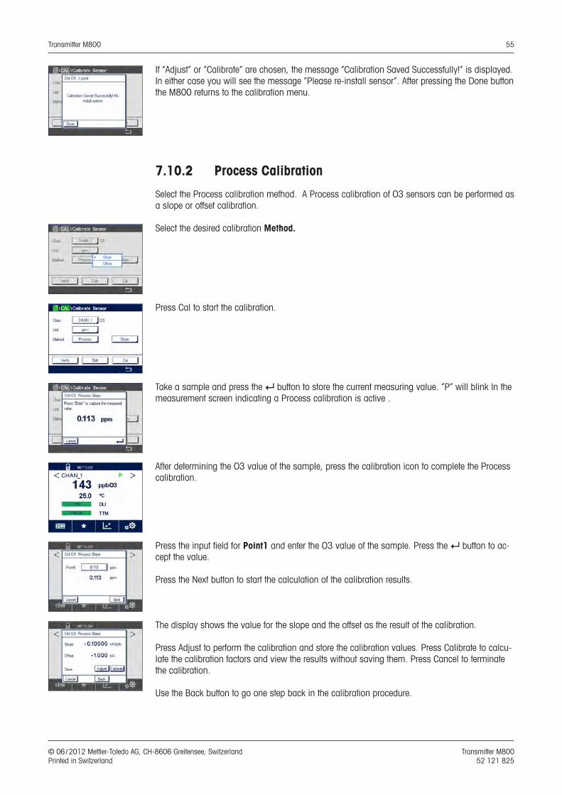
Transmitter M800 55
© 06 / 2012 Mettler-Toledo AG, CH-8606 Greifensee, Switzerland Transmitter M800 Printed in Switzerland 52 121 825
If ”Adjust” or ”Calibrate” are chosen, the message ”Calibration Saved Successfully!” is displayed. In either case you will see the message ”Please re-install sensor”. After pressing the Done button the M800 returns to the calibration menu.
7.10.2 Process Calibration
Select the Process calibration method. A Process calibration of O3 sensors can be performed as a slope or offset calibration.
Select the desired calibration Method.
Press Cal to start the calibration.
Take a sample and press the e button to store the current measuring value. “P” will blink In the measurement screen indicating a Process calibration is active .
After determining the O3 value of the sample, press the calibration icon to complete the Process calibration.
Press the input field for Point1 and enter the O3 value of the sample. Press the e button to ac-cept the value.
Press the Next button to start the calculation of the calibration results.
The display shows the value for the slope and the offset as the result of the calibration.
Press Adjust to perform the calibration and store the calibration values. Press Calibrate to calcu-late the calibration factors and view the results without saving them. Press Cancel to terminate the calibration.
Use the Back button to go one step back in the calibration procedure.
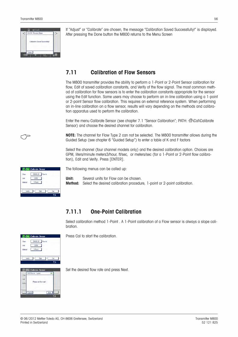
Transmitter M800 56
© 06 / 2012 Mettler-Toledo AG, CH-8606 Greifensee, Switzerland Transmitter M800 Printed in Switzerland 52 121 825
If ”Adjust” or ”Calibrate” are chosen, the message ”Calibration Saved Successfully!” is displayed. After pressing the Done button the M800 returns to the Menu Screen
7.11 Calibration of Flow Sensors
The M800 transmitter provides the ability to perform a 1-Point or 2-Point Sensor calibration for flow, Edit of saved calibration constants, and Verify of the flow signal. The most common meth-od of calibration for flow sensors is to enter the calibration constants appropriate for the sensor using the Edit function. Some users may choose to perform an in-line calibration using a 1-point or 2-point Sensor flow calibration. This requires an external reference system. When performing an in-line calibration on a flow sensor, results will vary depending on the methods and calibra-tion apparatus used to perform the calibration.
Enter the menu Calibrate Sensor (see chapter 7.1 “Sensor Calibration”; PATH: H\Cal\Calibrate Sensor) and choose the desired channel for calibration.
h NOTE: The channel for Flow Type 2 can not be selected. The M800 transmitter allows during the Guided Setup (see chapter 6 “Guided Setup”) to enter a table of K and F factors
Select the channel (four channel models only) and the desired calibration option. Choices are GPM, liters/minute meters3/hour, ft/sec, or meters/sec (for a 1-Point or 2-Point flow calibra-tion), Edit and Verify. Press [ENTER].
The following menus can be called up:
Unit: Several units for Flow can be chosen. Method: Select the desired calibration procedure, 1-point or 2-point calibration.
7.11.1 One-Point Calibration
Select calibration method 1-Point . A 1-Point calibration of a Flow sensor is always a slope cali-bration.
Press Cal to start the calibration.
Set the desired flow rate and press Next.
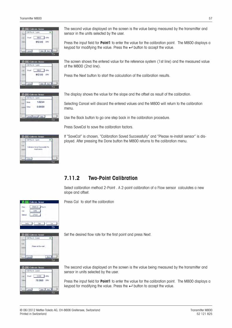
Transmitter M800 57
© 06 / 2012 Mettler-Toledo AG, CH-8606 Greifensee, Switzerland Transmitter M800 Printed in Switzerland 52 121 825
The second value displayed on the screen is the value being measured by the transmitter and sensor in the units selected by the user.
Press the input field for Point1 to enter the value for the calibration point. The M800 displays a keypad for modifying the value. Press the e button to accept the value.
The screen shows the entered value for the reference system (1st line) and the measured value of the M800 (2nd line).
Press the Next button to start the calculation of the calibration results.
The display shows the value for the slope and the offset as result of the calibration.
Selecting Cancel will discard the entered values and the M800 will return to the calibration menu.
Use the Back button to go one step back in the calibration procedure.
Press SaveCal to save the calibration factors.
If “SaveCal” is chosen, ”Calibration Saved Successfully” and “Please re-install sensor” is dis-played. After pressing the Done button the M800 returns to the calibration menu.
7.11.2 Two-Point Calibration
Select calibration method 2-Point . A 2-point calibration of a Flow sensor calculates a new slope and offset.
Press Cal to start the calibration
Set the desired flow rate for the first point and press Next.
The second value displayed on the screen is the value being measured by the transmitter and sensor in units selected by the user.
Press the input field for Point1 to enter the value for the calibration point. The M800 displays a keypad for modifying the value. Press the e button to accept the value.
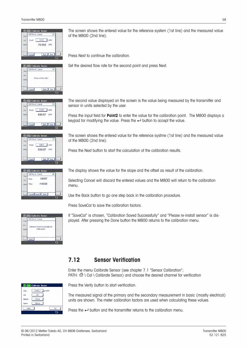
Transmitter M800 58
© 06 / 2012 Mettler-Toledo AG, CH-8606 Greifensee, Switzerland Transmitter M800 Printed in Switzerland 52 121 825
The screen shows the entered value for the reference system (1st line) and the measured value of the M800 (2nd line).
Press Next to continue the calibration.
Set the desired flow rate for the second point and press Next.
The second value displayed on the screen is the value being measured by the transmitter and sensor in units selected by the user.
Press the input field for Point2 to enter the value for the calibration point. The M800 displays a keypad for modifying the value. Press the e button to accept the value.
The screen shows the entered value for the reference systme (1st line) and the measured value of the M800 (2nd line).
Press the Next button to start the calculation of the calibration results.
The display shows the value for the slope and the offset as result of the calibration.
Selecting Cancel will discard the entered values and the M800 will return to the calibration menu.
Use the Back button to go one step back in the calibration procedure.
Press SaveCal to save the calibration factors.
If “SaveCal” is chosen, ”Calibration Saved Successfully” and “Please re-install sensor” is dis-played. After pressing the Done button the M800 returns to the calibration menu.
7.12 Sensor Verification
Enter the menu Calibrate Sensor (see chapter 7.1 “Sensor Calibration”; PATH: H \ Cal \ Calibrate Sensor) and choose the desired channel for verification
Press the Verify button to start verification.
The measured signal of the primary and the secondary measurement in basic (mostly electrical) units are shown. The meter calibration factors are used when calculating these values.
Press the e button and the transmitter returns to the calibration menu.
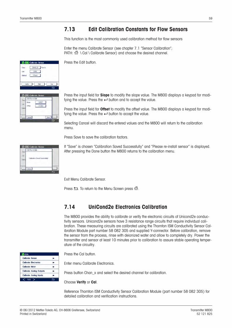
Transmitter M800 59
© 06 / 2012 Mettler-Toledo AG, CH-8606 Greifensee, Switzerland Transmitter M800 Printed in Switzerland 52 121 825
7.13 Edit Calibration Constants for Flow Sensors
This function is the most commonly used calibration method for flow sensors
Enter the menu Calibrate Sensor (see chapter 7.1 “Sensor Calibration”; PATH: H \ Cal \ Calibrate Sensor) and choose the desired channel.
Press the Edit button.
Press the input field for Slope to modify the slope value. The M800 displays a keypad for modi-fying the value. Press the e button and to accept the value.
Press the input field for Offset to modify the offset value. The M800 displays a keypad for modi-fying the value. Press the e button to accept the value.
Selecting Cancel will discard the entered values and the M800 will return to the calibration menu.
Press Save to save the calibration factors.
If “Save” is chosen ”Calibration Saved Successfully” and “Please re-install sensor” is displayed. After pressing the Done button the M800 returns to the calibration menu.
Exit Menu Calibrate Sensor.
Press p. To return to the Menu Screen press H.
7.14 UniCond2e Electronics Calibration
The M800 provides the ability to calibrate or verify the electronic circuits of Unicond2e conduc-tivity sensors. Unicond2e sensors have 3 resistance range circuits that require individual cali-bration. These measuring circuits are calibrated using the Thornton ISM Conductivity Sensor Cal-ibration Module part number 58 082 305 and supplied Y-connector. Before calibration, remove the sensor from the process, rinse with deionized water and allow to completely dry. Power the transmitter and sensor at least 10 minutes prior to calibration to assure stable operating temper-ature of the circuitry.
Press the Cal button.
Enter menu Calibrate Electronics.
Press button Chan_x and select the desired channel for calibration.
Choose Verify or Cal.
Reference Thornton ISM Conductivity Sensor Calibration Module (part number 58 082 305) for detailed calibration and verification instructions.
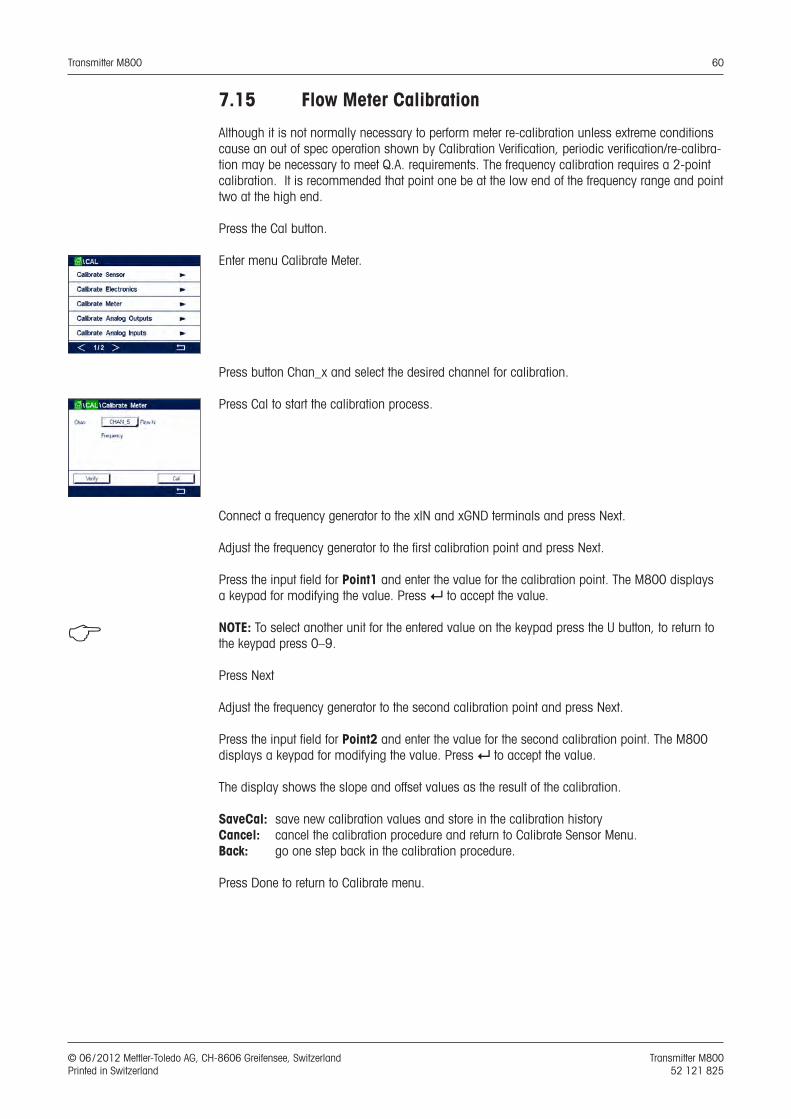
Transmitter M800 60
© 06 / 2012 Mettler-Toledo AG, CH-8606 Greifensee, Switzerland Transmitter M800 Printed in Switzerland 52 121 825
7.15 Flow Meter Calibration
Although it is not normally necessary to perform meter re-calibration unless extreme conditions cause an out of spec operation shown by Calibration Verification, periodic verification/re-calibra-tion may be necessary to meet Q.A. requirements. The frequency calibration requires a 2-point calibration. It is recommended that point one be at the low end of the frequency range and point two at the high end.
Press the Cal button.
Enter menu Calibrate Meter.
Press button Chan_x and select the desired channel for calibration.
Press Cal to start the calibration process.
Connect a frequency generator to the xIN and xGND terminals and press Next.
Adjust the frequency generator to the first calibration point and press Next.
Press the input field for Point1 and enter the value for the calibration point. The M800 displays a keypad for modifying the value. Press e to accept the value.
h NOTE: To select another unit for the entered value on the keypad press the U button, to return to the keypad press 0–9.
Press Next
Adjust the frequency generator to the second calibration point and press Next.
Press the input field for Point2 and enter the value for the second calibration point. The M800 displays a keypad for modifying the value. Press e to accept the value.
The display shows the slope and offset values as the result of the calibration.
SaveCal: save new calibration values and store in the calibration historyCancel: cancel the calibration procedure and return to Calibrate Sensor Menu.Back: go one step back in the calibration procedure.
Press Done to return to Calibrate menu.
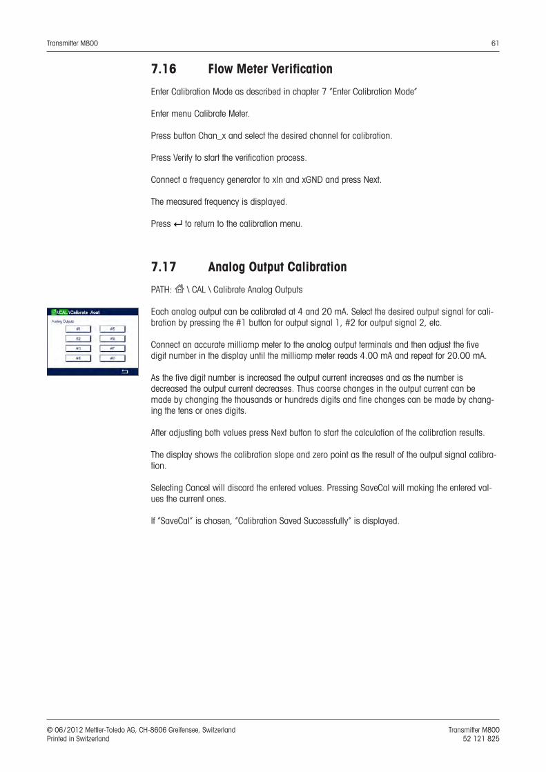
Transmitter M800 61
© 06 / 2012 Mettler-Toledo AG, CH-8606 Greifensee, Switzerland Transmitter M800 Printed in Switzerland 52 121 825
7.16 Flow Meter Verification
Enter Calibration Mode as described in chapter 7 “Enter Calibration Mode”
Enter menu Calibrate Meter.
Press button Chan_x and select the desired channel for calibration.
Press Verify to start the verification process.
Connect a frequency generator to xIn and xGND and press Next.
The measured frequency is displayed.
Press e to return to the calibration menu.
7.17 Analog Output Calibration
PATH: H \ CAL \ Calibrate Analog Outputs
Each analog output can be calibrated at 4 and 20 mA. Select the desired output signal for cali-bration by pressing the #1 button for output signal 1, #2 for output signal 2, etc.
Connect an accurate milliamp meter to the analog output terminals and then adjust the five digit number in the display until the milliamp meter reads 4.00 mA and repeat for 20.00 mA.
As the five digit number is increased the output current increases and as the number is decreased the output current decreases. Thus coarse changes in the output current can be made by changing the thousands or hundreds digits and fine changes can be made by chang-ing the tens or ones digits.
After adjusting both values press Next button to start the calculation of the calibration results.
The display shows the calibration slope and zero point as the result of the output signal calibra-tion.
Selecting Cancel will discard the entered values. Pressing SaveCal will making the entered val-ues the current ones.
If “SaveCal” is chosen, ”Calibration Saved Successfully” is displayed.
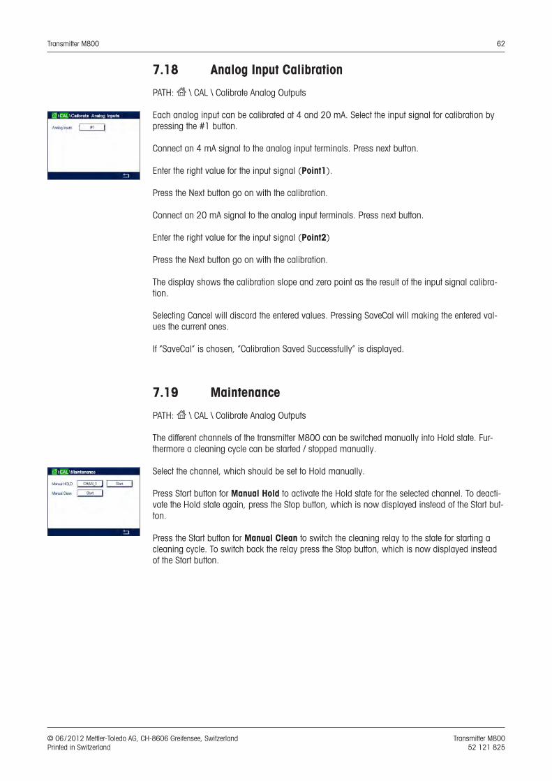
Transmitter M800 62
© 06 / 2012 Mettler-Toledo AG, CH-8606 Greifensee, Switzerland Transmitter M800 Printed in Switzerland 52 121 825
7.18 Analog Input Calibration
PATH: H \ CAL \ Calibrate Analog Outputs
Each analog input can be calibrated at 4 and 20 mA. Select the input signal for calibration by pressing the #1 button.
Connect an 4 mA signal to the analog input terminals. Press next button.
Enter the right value for the input signal (Point1).
Press the Next button go on with the calibration.
Connect an 20 mA signal to the analog input terminals. Press next button.
Enter the right value for the input signal (Point2)
Press the Next button go on with the calibration.
The display shows the calibration slope and zero point as the result of the input signal calibra-tion.
Selecting Cancel will discard the entered values. Pressing SaveCal will making the entered val-ues the current ones.
If “SaveCal” is chosen, ”Calibration Saved Successfully” is displayed.
7.19 Maintenance
PATH: H \ CAL \ Calibrate Analog Outputs
The different channels of the transmitter M800 can be switched manually into Hold state. Fur-thermore a cleaning cycle can be started / stopped manually.
Select the channel, which should be set to Hold manually.
Press Start button for Manual Hold to activate the Hold state for the selected channel. To deacti-vate the Hold state again, press the Stop button, which is now displayed instead of the Start but-ton.
Press the Start button for Manual Clean to switch the cleaning relay to the state for starting a cleaning cycle. To switch back the relay press the Stop button, which is now displayed instead of the Start button.
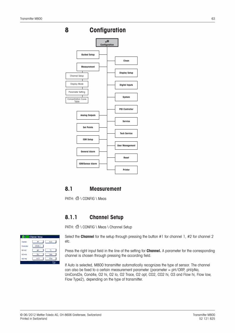
Transmitter M800 63
© 06 / 2012 Mettler-Toledo AG, CH-8606 Greifensee, Switzerland Transmitter M800 Printed in Switzerland 52 121 825
8 Configuration
CConfiguration
Guided Setup
Measurement
Analog Outputs
Set Points
ISM Setup
General Alarm
ISM/Sensor Alarm
Display Setup
Digital Inputs
System
PID Controller
Service
Tech Service
User Management
Reset
Clean
Channel Setup
Display Mode
Parameter Setting
Concentration Curve Table
Printer
8.1 Measurement
PATH: H \ CONFIG \ Meas
8.1.1 Channel Setup
PATH: H \ CONFIG \ Meas \ Channel Setup
Select the Channel for the setup through pressing the button #1 for channel 1, #2 for channel 2 etc.
Press the right input field in the line of the setting for Channel. A parameter for the corresponding channel is chosen through pressing the according field.
If Auto is selected, M800 transmitter automatically recognizes the type of sensor. The channel can also be fixed to a certain measurement parameter (parameter = pH / ORP, pH/pNa, UniCond2e, Cond4e, O2 hi, 02 lo, O2 Trace, O2 opt, CO2, CO2 hi, O3 and Flow hi, Flow low, Flow Type2), depending on the type of trans mitter.

Transmitter M800 64
© 06 / 2012 Mettler-Toledo AG, CH-8606 Greifensee, Switzerland Transmitter M800 Printed in Switzerland 52 121 825
Measurement parameter TypepH / ORP = pH and ORP Water, ProcesspH/pNa = pH and ORP (with pH/pNa electrode) ProcessUniCond2e = 2 electrode conductivity Water, ProcessCond4e = 4 electrode conductivity Water, ProcessO2 hi = Dissolved oxygen or oxygen in gas (ppm) ProcessO2 lo = Dissolved oxygen or oxygen in gas (ppb) ProcessO2 Trace = Dissolved oxygen or oxygen in gas ProcessO2 Opt = Dissolved oxygen optical ProcessO2 lo Thornton = Dissolved oxygen WaterCO2 = Dissolved carbon dioxide ProcessCO2 hi = Dissolved carbon dioxide for beverages ProcessTOC = Total organic carbon WaterO3 = Dissolved O3 WaterFlow hi, low, Type2 = Flow Water
Enter the name with a maximum length of 6 characters for the channel through pressing the in-put field in the line Descriptor. The name of the channel will always be displayed, if the channel has to be selected. The name will also be displayed on the in the Start Screen and Menu Screen if the Display Mode (see chapter 8.1.3 “Display Mode”) has been set to 1-Channel or 2-Chan-nel.
Choose one of the measurements M1 to M6 (e.g. for measuring value M1 the left button, for measuring M2 the right button in the corresponding line).
Select in the input field for Measurement the desired parameter to show.
h NOTE: Beside the parameters pH, O2, T, etc. also the ISM values DLI, TTM and ACT can be linked to the measurements.
Choose Range factor of the measuring value. Not all parameters allow a modification of the range.
The menu Resolution allows the setting of the resolution for the measurement. The accuracy of the measurement is not effected by this setting. Possible setting are 1, 0.1, 0.01, 0.001.
Selected the menu Filter. The averaging method (noise filter) for the measurement can be se-lected. The options are None (default), Low, Medium, High and Special.None = no averaging or filteringLow = equivalent to a 3 point moving averageMedium = equivalent to a 6 point moving averageHigh = equivalent to a 10 point moving averageSpecial = averaging depending on signal change (normally High averaging but Low averaging
for large changes in input signal)
8.1.2 Derived Measurements
The M800 enables the setup of derived measurements (total, difference, ratio) based on two measuring values like pH, conductivity, etc.. To get the derived measurements, first set up the two primary measurements, which will be used to calculate the derived measurement. Define the primary measurements as if they were stand-alone readings. Then chose the corresponding unit for the derived measurement for the first channel. The transmitter M800 will displays an addi-tional menu Other Channel to select the second channel with the corresponding measurement.
There are three additional derived measurements available for configuration with two conductivi-ty sensors: %Rej (% Rejection), pH Cal (Calculated pH) and CO2 Cal (Calculated CO2).

Transmitter M800 65
© 06 / 2012 Mettler-Toledo AG, CH-8606 Greifensee, Switzerland Transmitter M800 Printed in Switzerland 52 121 825
8.1.2.1 % Rejection measurement
For reverse osmosis (RO) applications, percent rejection is measured with conductivity to deter-mine the ratio of impurities removed from product or permeate water to the total impurities in the incoming feed water. The formula for obtaining Percent Rejection is:[1 – (Product/Feed)] X 100 = % RejectionWhere Product and Feed are the conductivity values measured by the respective sensors. Figure a shows a diagram of an RO installation with sensors installed for Percent Rejection.
Reverse Osmosis Membrane
Feed Product
Reject
ConductivitySensor
B
ConductivitySensor
A
Figure a: % Rejection
h NOTE: The product monitoring sensor must be on the channel that will measure percent rejec-tion. If the product conductivity sensor is installed in channel 1, then percent rejection must be measured in channel 1.
8.1.2.2 Calculated pH (Power Plant Applications only)
Calculated pH may be obtained very accurately from specific and cation conductivity values on power plant samples when the pH is between 7.5 and 10.5 due to ammonia or amines and when the specific conductivity is significantly greater than the cation conductivity. This calcula-tion is not suitable where significant levels of phosphates are present. The M800 uses this algo-rithm when pH Cal is selected as a measurement.
The calculated pH must be configured on the same channel as specific conductivity. For exam-ple, set up measurement M1 on CHAN_1 to be specific conductivity, measurement M1 on CHAN_2 to be cation conductivity, measurement M2 on CHAN_1 to be calculated pH and mea-surement M3 on CHAN_1 to be temperature. Set the temperature compensation mode to ”Am-monia” for measurement M1 on CHAN_1 and to ”Cation” for measurement M1 on CHAN_2.
h NOTE: If operation goes outside the recommended conditions, a glass electrode pH measure-ment is needed to obtain an accurate value. On the other hand, when sample conditions are within the ranges noted above, the calculated pH provides an accurate standard for one-point trim calibration of the electrode pH measurement.
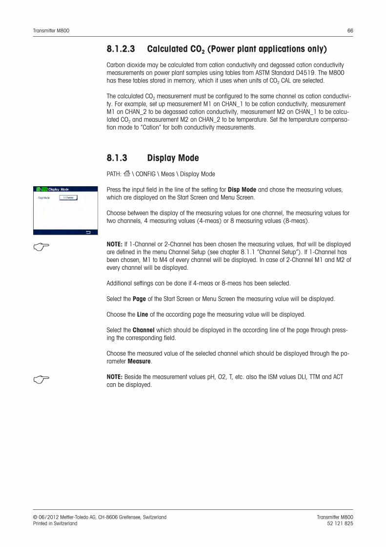
Transmitter M800 66
© 06 / 2012 Mettler-Toledo AG, CH-8606 Greifensee, Switzerland Transmitter M800 Printed in Switzerland 52 121 825
8.1.2.3 Calculated CO2 (Power plant applications only)
Carbon dioxide may be calculated from cation conductivity and degassed cation conductivity measurements on power plant samples using tables from ASTM Standard D4519. The M800 has these tables stored in memory, which it uses when units of CO2 CAL are selected.
The calculated CO2 measurement must be configured to the same channel as cation conductivi-ty. For example, set up measurement M1 on CHAN_1 to be cation conductivity, measurement M1 on CHAN_2 to be degassed cation conductivity, measurement M2 on CHAN_1 to be calcu-lated CO2 and measurement M2 on CHAN_2 to be temperature. Set the temperature compensa-tion mode to ”Cation” for both conductivity measurements.
8.1.3 Display Mode
PATH: H \ CONFIG \ Meas \ Display Mode
Press the input field in the line of the setting for Disp Mode and chose the measuring values, which are displayed on the Start Screen and Menu Screen.
Choose between the display of the measuring values for one channel, the measuring values for two channels, 4 measuring values (4-meas) or 8 measuring values (8-meas).
h NOTE: If 1-Channel or 2-Channel has been chosen the measuring values, that will be displayed are defined in the menu Channel Setup (see chapter 8.1.1 “Channel Setup”). If 1-Channel has been chosen, M1 to M4 of every channel will be displayed. In case of 2-Channel M1 and M2 of every channel will be displayed.
Additional settings can be done if 4-meas or 8-meas has been selected.
Select the Page of the Start Screen or Menu Screen the measuring value will be displayed.
Choose the Line of the according page the measuring value will be displayed.
Select the Channel which should be displayed in the according line of the page through press-ing the corresponding field.
Choose the measured value of the selected channel which should be displayed through the pa-rameter Measure.
h NOTE: Beside the measurement values pH, O2, T, etc. also the ISM values DLI, TTM and ACT can be displayed.
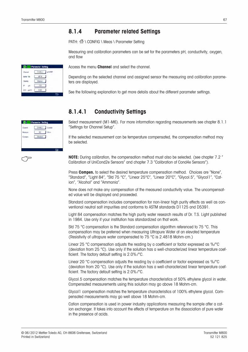
Transmitter M800 67
© 06 / 2012 Mettler-Toledo AG, CH-8606 Greifensee, Switzerland Transmitter M800 Printed in Switzerland 52 121 825
8.1.4 Parameter related Settings
PATH: H \ CONFIG \ Meas \ Parameter Setting
Measuring and calibration parameters can be set for the parameters pH, conductivity, oxygen, and flow
Access the menu Channel and select the channel.
Depending on the selected channel and assigned sensor the measuring and calibration parame-ters are displayed.
See the following explanation to get more details about the different parameter settings.
8.1.4.1 Conductivity Settings
Select measurement (M1-M6). For more information regarding measurements see chapter 8.1.1 “Settings for Channel Setup”.
If the selected measurement can be temperature compensated, the compensation method may be selected.
h NOTE: During calibration, the compensation method must also be selected. (see chapter 7.2 “ Calibration of UniCond2e Sensors” and chapter 7.3 “Calibration of Cond4e Sensors”).
Press Compen. to select the desired temperature compensation method. Choices are “None”, ”Standard”, “Light 84”, “Std 75 °C”, ”Linear 25°C”, ”Linear 20°C”, “Glycol.5”, “Glycol1”, “Cat-ion”, “Alcohol” and “Ammonia”.
None does not make any compensation of the measured conductivity value. The uncompensat-ed value will be displayed and proceeded.
Standard compensation includes compensation for non-linear high purity effects as well as con-ventional neutral salt impurities and conforms to ASTM standards D1125 and D5391.
Light 84 compensation matches the high purity water research results of Dr. T.S. Light published in 1984. Use only if your institution has standardized on that work.
Std 75 °C compensation is the Standard compensation algorithm referenced to 75 °C. This compensation may be preferred when measuring Ultrapure Water at an elevated temperature (Resistivity of ultrapure water compensated to 75 °C is 2.4818 Mohm-cm.)
Linear 25 °C compensation adjusts the reading by a coefficient or factor expressed as %/°C (deviation from 25 °C). Use only if the solution has a well-characterized linear temperature coef-ficient. The factory default setting is 2.0% /°C.
Linear 20 °C compensation adjusts the reading by a coefficient or factor expressed as %/°C (deviation from 20 °C). Use only if the solution has a well-characterized linear temperature coef-ficient. The factory default setting is 2.0% /°C.
Glycol.5 compensation matches the temperature characteristics of 50% ethylene glycol in water. Compensated measurements using this solution may go above 18 Mohm-cm.
Glycol1 compensation matches the temperature characteristics of 100% ethylene glycol. Com-pensated measurements may go well above 18 Mohm-cm.
Cation compensation is used in power industry applications measuring the sample after a cat-ion exchanger. It takes into account the effects of temperature on the dissociation of pure water in the presence of acids.
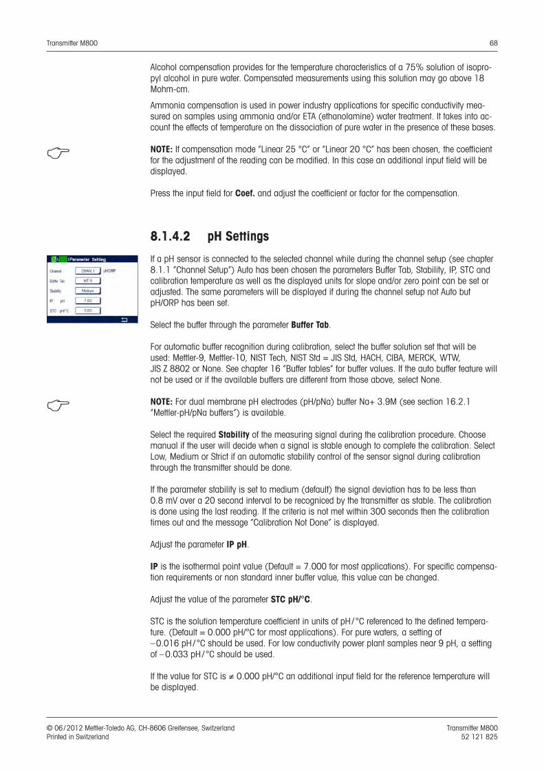
Transmitter M800 68
© 06 / 2012 Mettler-Toledo AG, CH-8606 Greifensee, Switzerland Transmitter M800 Printed in Switzerland 52 121 825
Alcohol compensation provides for the temperature characteristics of a 75% solution of isopro-pyl alcohol in pure water. Compensated measurements using this solution may go above 18 Mohm-cm.
Ammonia compensation is used in power industry applications for specific conductivity mea-sured on samples using ammonia and/or ETA (ethanolamine) water treatment. It takes into ac-count the effects of temperature on the dissociation of pure water in the presence of these bases.
h NOTE: If compensation mode ”Linear 25 °C” or ”Linear 20 °C” has been chosen, the coefficient for the adjustment of the reading can be modified. In this case an additional input field will be displayed.
Press the input field for Coef. and adjust the coefficient or factor for the compensation.
8.1.4.2 pH Settings
If a pH sensor is connected to the selected channel while during the channel setup (see chapter 8.1.1 “Channel Setup”) Auto has been chosen the parameters Buffer Tab, Stability, IP, STC and calibration temperature as well as the displayed units for slope and/or zero point can be set or adjusted. The same parameters will be displayed if during the channel setup not Auto but pH/ORP has been set.
Select the buffer through the parameter Buffer Tab.
For automatic buffer recognition during calibration, select the buffer solution set that will be used: Mettler-9, Mettler-10, NIST Tech, NIST Std = JIS Std, HACH, CIBA, MERCK, WTW, JIS Z 8802 or None. See chapter 16 “Buffer tables” for buffer values. If the auto buffer feature will not be used or if the available buffers are different from those above, select None.
h NOTE: For dual membrane pH electrodes (pH/pNa) buffer Na+ 3.9M (see section 16.2.1 “Mettler-pH/pNa buffers”) is available.
Select the required Stability of the measuring signal during the calibration procedure. Choose manual if the user will decide when a signal is stable enough to complete the calibration. Select Low, Medium or Strict if an automatic stability control of the sensor signal during calibration through the transmitter should be done.
If the parameter stability is set to medium (default) the signal deviation has to be less than 0.8 mV over a 20 second interval to be recogniced by the transmitter as stable. The calibration is done using the last reading. If the criteria is not met within 300 seconds then the calibration times out and the message ”Calibration Not Done” is displayed.
Adjust the parameter IP pH.
IP is the isothermal point value (Default = 7.000 for most applications). For specific compensa-tion requirements or non standard inner buffer value, this value can be changed.
Adjust the value of the parameter STC pH/°C.
STC is the solution temperature coefficient in units of pH / °C referenced to the defined tempera-ture. (Default = 0.000 pH/°C for most applications). For pure waters, a setting of – 0.016 pH / °C should be used. For low conductivity power plant samples near 9 pH, a setting of – 0.033 pH / °C should be used.
If the value for STC is ≠ 0.000 pH/°C an additional input field for the reference temperature will be displayed.
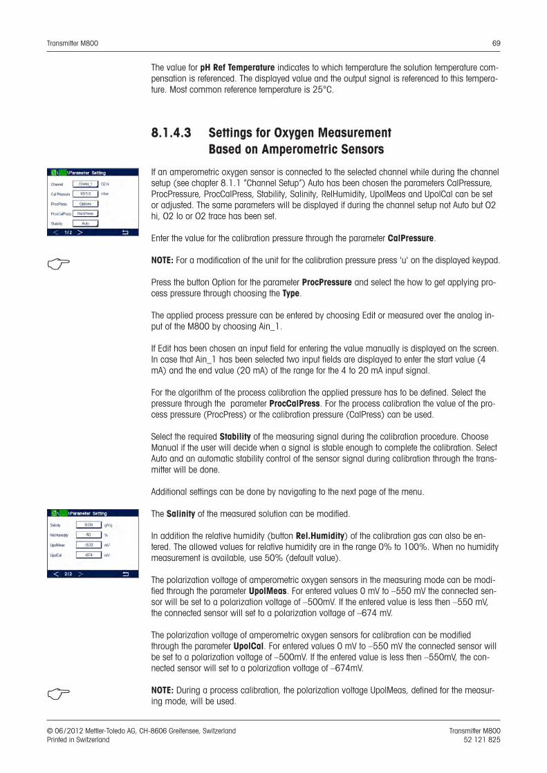
Transmitter M800 69
© 06 / 2012 Mettler-Toledo AG, CH-8606 Greifensee, Switzerland Transmitter M800 Printed in Switzerland 52 121 825
The value for pH Ref Temperature indicates to which temperature the solution temperature com-pensation is referenced. The displayed value and the output signal is referenced to this tempera-ture. Most common reference temperature is 25°C.
8.1.4.3 Settings for Oxygen Measurement Based on Amperometric Sensors
If an amperometric oxygen sensor is connected to the selected channel while during the channel setup (see chapter 8.1.1 “Channel Setup”) Auto has been chosen the parameters CalPressure, ProcPressure, ProcCalPress, Stability, Salinity, RelHumidity, UpolMeas and UpolCal can be set or adjusted. The same parameters will be displayed if during the channel setup not Auto but O2 hi, O2 lo or O2 trace has been set.
Enter the value for the calibration pressure through the parameter CalPressure.
h NOTE: For a modification of the unit for the calibration pressure press 'u' on the displayed keypad.
Press the button Option for the parameter ProcPressure and select the how to get applying pro-cess pressure through choosing the Type.
The applied process pressure can be entered by choosing Edit or measured over the analog in-put of the M800 by choosing Ain_1.
If Edit has been chosen an input field for entering the value manually is displayed on the screen. In case that Ain_1 has been selected two input fields are displayed to enter the start value (4 mA) and the end value (20 mA) of the range for the 4 to 20 mA input signal.
For the algorithm of the process calibration the applied pressure has to be defined. Select the pressure through the parameter ProcCalPress. For the process calibration the value of the pro-cess pressure (ProcPress) or the calibration pressure (CalPress) can be used.
Select the required Stability of the measuring signal during the calibration procedure. Choose Manual if the user will decide when a signal is stable enough to complete the calibration. Select Auto and an automatic stability control of the sensor signal during calibration through the trans-mitter will be done.
Additional settings can be done by navigating to the next page of the menu.
The Salinity of the measured solution can be modified.
In addition the relative humidity (button Rel.Humidity) of the calibration gas can also be en-tered. The allowed values for relative humidity are in the range 0% to 100%. When no humidity measurement is available, use 50% (default value).
The polarization voltage of amperometric oxygen sensors in the measuring mode can be modi-fied through the parameter UpolMeas. For entered values 0 mV to –550 mV the connected sen-sor will be set to a polarization voltage of –500mV. If the entered value is less then –550 mV, the connected sensor will set to a polarization voltage of –674 mV.
The polarization voltage of amperometric oxygen sensors for calibration can be modified through the parameter UpolCal. For entered values 0 mV to –550 mV the connected sensor will be set to a polarization voltage of –500mV. If the entered value is less then –550mV, the con-nected sensor will set to a polarization voltage of –674mV.
h NOTE: During a process calibration, the polarization voltage UpolMeas, defined for the measur-ing mode, will be used.
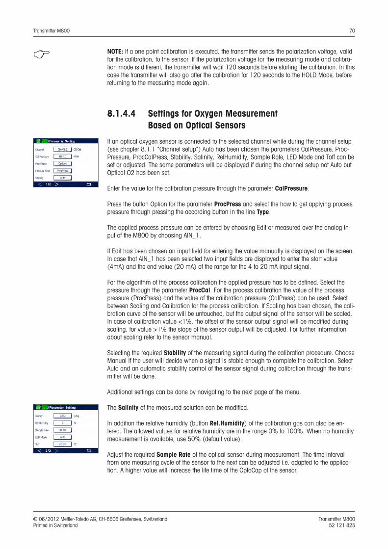
Transmitter M800 70
© 06 / 2012 Mettler-Toledo AG, CH-8606 Greifensee, Switzerland Transmitter M800 Printed in Switzerland 52 121 825
h NOTE: If a one point calibration is executed, the transmitter sends the polarization voltage, valid for the calibration, to the sensor. If the polarization voltage for the measuring mode and calibra-tion mode is different, the transmitter will wait 120 seconds before starting the calibration. In this case the transmitter will also go after the calibration for 120 seconds to the HOLD Mode, before returning to the measuring mode again.
8.1.4.4 Settings for Oxygen Measurement Based on Optical Sensors
If an optical oxygen sensor is connected to the selected channel while during the channel setup (see chapter 8.1.1 “Channel setup”) Auto has been chosen the parameters CalPressure, Proc-Pressure, ProcCalPress, Stability, Salinity, RelHumidity, Sample Rate, LED Mode and Toff can be set or adjusted. The same parameters will be displayed if during the channel setup not Auto but Optical O2 has been set.
Enter the value for the calibration pressure through the parameter CalPressure.
Press the button Option for the parameter ProcPress and select the how to get applying process pressure through pressing the according button in the line Type.
The applied process pressure can be entered by choosing Edit or measured over the analog in-put of the M800 by choosing AIN_1.
If Edit has been chosen an input field for entering the value manually is displayed on the screen. In case that AIN_1 has been selected two input fields are displayed to enter the start value (4mA) and the end value (20 mA) of the range for the 4 to 20 mA input signal.
For the algorithm of the process calibration the applied pressure has to be defined. Select the pressure through the parameter ProcCal. For the process calibration the value of the process pressure (ProcPress) and the value of the calibration pressure (CalPress) can be used. Select between Scaling and Calibration for the process calibration. If Scaling has been chosen, the cali-bration curve of the sensor will be untouched, but the output signal of the sensor will be scaled. In case of calibration value <1%, the offset of the sensor output signal will be modified during scaling, for value >1% the slope of the sensor output will be adjusted. For further information about scaling refer to the sensor manual.
Selecting the required Stability of the measuring signal during the calibration procedure. Choose Manual if the user will decide when a signal is stable enough to complete the calibration. Select Auto and an automatic stability control of the sensor signal during calibration through the trans-mitter will be done.
Additional settings can be done by navigating to the next page of the menu.
The Salinity of the measured solution can be modified.
In addition the relative humidity (button Rel.Humidity) of the calibration gas can also be en-tered. The allowed values for relative humidity are in the range 0% to 100%. When no humidity measurement is available, use 50% (default value).
Adjust the required Sample Rate of the optical sensor during measurement. The time interval from one measuring cycle of the sensor to the next can be adjusted i.e. adapted to the applica-tion. A higher value will increase the life time of the OptoCap of the sensor.
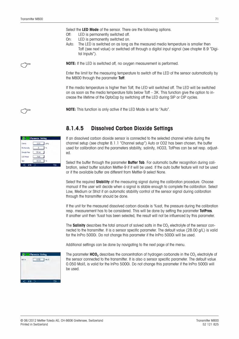
Transmitter M800 71
© 06 / 2012 Mettler-Toledo AG, CH-8606 Greifensee, Switzerland Transmitter M800 Printed in Switzerland 52 121 825
Select the LED Mode of the sensor. There are the following options. Off: LED is permanently switched off. On: LED is permanently switched on. Auto: The LED is switched on as long as the measured media temperature is smaller then
Toff (see next value) or switched off through a digital input signal (see chapter 8.9 “Digi-tal Inputs”).
h NOTE: If the LED is switched off, no oxygen measurement is performed.
Enter the limit for the measuring temperature to switch off the LED of the sensor automatically by the M800 through the parameter Toff.
If the media temperature is higher then Toff, the LED will switched off. The LED will be switched on as soon as the media temperature falls below Toff – 3K. This function give the option to in-crease the lifetime of the OptoCap by switching off the LED during SIP or CIP cycles.
h NOTE: This function is only active if the LED Mode is set to “Auto”.
8.1.4.5 Dissolved Carbon Dioxide Settings
If an dissolved carbon dioxide sensor is connected to the selected channel while during the channel setup (see chapter 8.1.1 “Channel setup”) Auto or CO2 has been chosen, the buffer used for calibration and the parameters stability, salinity, HCO3, TotPres can be set resp. adjust-ed.
Select the buffer through the parameter Buffer Tab. For automatic buffer recognition during cali-bration, select buffer solution Mettler-9 if it will be used. If the auto buffer feature will not be used or if the available buffer are different from Mettler-9 select None.
Select the required Stability of the measuring signal during the calibration procedure. Choose manual if the user will decide when a signal is stable enough to complete the calibration. Select Low, Medium or Strict if an automatic stability control of the sensor signal during calibration through the transmitter should be done.
If the unit for the measured dissolved carbon dioxide is %sat, the pressure during the calibration resp. measurement has to be considered. This will be done by setting the parameter TotPres. If another unit then %sat has been selected, the result will not be influenced by this parameter.
The Salinity describes the total amount of solved salts in the CO2 electrolyte of the sensor con-nected to the transmitter. It is a sensor specific parameter. The default value (28.00 g/L) is valid for the InPro 5000i. Do not change this parameter if the InPro 5000i will be used.
Additional settings can be done by navigating to the next page of the menu.
The parameter HCO3 describes the concentration of hydrogen carbonate in the CO2 electrolyte of the sensor connected to the transmitter. It is also a sensor specific parameter. The default value 0.050 Mol/L is valid for the InPro 5000i. Do not change this parameter if the InPro 5000i will be used.
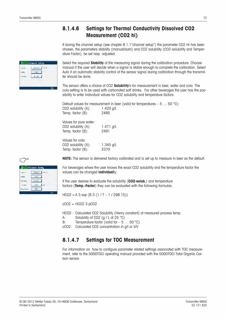
Transmitter M800 72
© 06 / 2012 Mettler-Toledo AG, CH-8606 Greifensee, Switzerland Transmitter M800 Printed in Switzerland 52 121 825
8.1.4.6 Settings for Thermal Conductivity Dissolved CO2 Measurement (CO2 hi)
If during the channel setup (see chapter 8.1.1“channel setup”) the parameter CO2 Hi has been chosen, the parameters stability (manual/auto) and CO2 solubility (CO2-solubility and Temper-ature Factor), be set resp. adjusted.
Select the required Stability of the measuring signal during the calibration procedure. Choose manual if the user will decide when a signal is stable enough to complete the calibration. Select Auto if an automatic stability control of the sensor signal during calibration through the transmit-ter should be done.
The sensor offers a choice of CO2 Solubility’s for measurement in beer, water and cola. The cola setting is to be used with carbonated soft drinks. For other beverages the user has the pos-sibility to enter individual values for CO2 solubility and temperature factors.
Default values for measurement in beer (valid for temperatures – 5 … 50 °C):CO2 solubility (A): 1.420 g/LTemp. factor (B): 2485
Values for pure water:CO2 solubility (A): 1.471 g/LTemp. factor (B): 2491
Values for cola:CO2 solubility (A): 1.345 g/LTemp. factor (B): 2370
h NOTE: The sensor is delivered factory calibrated and is set up to measure in beer as the default.
For beverages where the user knows the exact CO2 solubility and the temperature factor thevalues can be changed individually.
If the user desires to evaluate the solubility (CO2-solub.) and temperaturefactors (Temp.-Factor) they can be evaluated with the following formulas.
HCO2 = A 3 exp (B 3 (1 / T – 1 / 298.15))
cCO2 = HCO2 3 pCO2
HCO2 : Calculated CO2 Solubility (Henry constant) at measured process temp.A: Solubility of CO2 (g / L at 25 °C)B: Temperature factor (valid for – 5 … 50 °C)cCO2: Calculated CO2 concentration in g/l or V/V
8.1.4.7 Settings for TOC Measurement
For information on how to configure parameter related settings associated with TOC measure-ment, refer to the 5000TOCi operating manual provided with the 5000TOCi Total Organic Car-bon sensor.
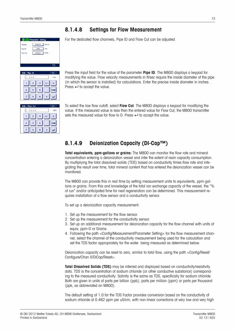
Transmitter M800 73
© 06 / 2012 Mettler-Toledo AG, CH-8606 Greifensee, Switzerland Transmitter M800 Printed in Switzerland 52 121 825
8.1.4.8 Settings for Flow Measurement
For the dedicated flow channels, Pipe ID and Flow Cut can be adjusted
Press the input field for the value of the parameter Pipe ID. The M800 displays a keypad for modifying the value. Flow velocity measurements in ft/sec require the inside diameter of the pipe (in which the sensor is installed) for calculations. Enter the precise inside diameter in inches. . Press e to accept the value.
To select the low flow cutoff, select Flow Cut. The M800 displays a keypad for modifying the value. If the measured value is less then the entered value for Flow Cut, the M800 transmitter sets the measured value for flow to 0. Press e to accept the value.
8.1.4.9 Deionization Capacity (DI-Cap™)
Total equivalents, ppm-gallons or grains: The M800 can monitor the flow rate and mineral concentration entering a deionization vessel and infer the extent of resin capacity consumption. By multiplying the total dissolved solids (TDS) based on conductivity times flow rate and inte-grating the result over time, total mineral content that has entered the deionization vessel can be monitored.
The M800 can provide this in real time by setting measurement units to equivalents, ppm-gal-lons or grains. From this and knowledge of the total ion exchange capacity of the vessel, the “% of run” and/or anticipated time for next regeneration can be determined. This measurement re-quires installation of a flow sensor and a conductivity sensor.
To set up a deionization capacity measurement:
1. Set up the measurement for the flow sensor.2. Set up the measurement for the conductivity sensor.3. Set up an additional measurement for deionization capacity for the flow channel with units of
equiv, ppm-G or Grains.4. Following the path <Config/Measurement/Parameter Setting> for the flow measurement chan-
nel, select the channel of the conductivity measurement being used for the calculation and set the TDS factor appropriately for the water being measured as determined below.
Deionization capacity can be reset to zero, similar to total flow, using the path <Config/Reset/Configure/Chan X/DiCap/Reset>.
Total Dissolved Solids (TDS) may be inferred and displayed based on conductivity/resistivity data. TDS is the concentration of sodium chloride (or other conductive substance) correspond-ing to the measured conductivity. Salinity is the same as TDS, specifically for sodium chloride. Both are given in units of parts per billion (ppb), parts per million (ppm) or parts per thousand (ppk, as abbreviated on M800).
The default setting of 1.0 for the TDS Factor provides conversion based on the conductivity of sodium chloride at 0.462 ppm per uS/cm, with non-linear corrections at very low and very high
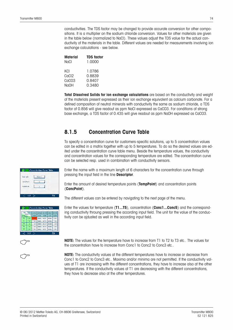
Transmitter M800 74
© 06 / 2012 Mettler-Toledo AG, CH-8606 Greifensee, Switzerland Transmitter M800 Printed in Switzerland 52 121 825
conductivities. The TDS factor may be changed to provide accurate conversion for other compo-sitions. It is a multiplier on the sodium chloride conversion. Values for other materials are given in the table below (normalized to NaCl). These values adjust the TDS value for the actual con-ductivity of the materials in the table. Different values are needed for measurements involving ion exchange calculations - see below.
Material TDS factorNaCl 1.0000
KCl 1.0786CaCl2 0.8839CaCO3 0.8407NaOH 0.3480
Total Dissolved Solids for ion exchange calculations are based on the conductivity and weight of the materials present expressed as their ion exchange equivalent as calcium carbonate. For a defined composition of neutral minerals with conductivity the same as sodium chloride, a TDS factor of 0.856 will give readout as ppm NaCl expressed as CaCO3. For conditions of strong base exchange, a TDS factor of 0.435 will give readout as ppm NaOH expressed as CaCO3.
8.1.5 Concentration Curve Table
To specify a concentration curve for customers-specific solutions, up to 5 concentration values can be edited in a matrix together with up to 5 temperatures. To do so the desired values are ed-ited under the concentration curve table menu. Beside the temperature values, the conductivity and concentration values for the corresponding temperature are edited. The concentration curve can be selected resp. used in combination with conductivity sensors.
Enter the name with a maximum length of 6 characters for the concentration curve through pressing the input field in the line Descriptor.
Enter the amount of desired temperature points (TempPoint) and concentration points (ConcPoint).
The different values can be entered by navigating to the next page of the menu.
Enter the values for temperature (T1...T5), concentration (Conc1...Conc5) and the correspond-ing conductivity throung pressing the according input field. The unit for the value of the conduc-tivity can be ajdusted as well in the according input field.
h NOTE: The values for the temperature have to increase from T1 to T2 to T3 etc.. The values for the concentration have to increase from Conc1 to Conc2 to Conc3 etc..
h NOTE: The conductivity values at the different temperatures have to increase or decrease from Conc1 to Conc2 to Conc3 etc.. Maxima and/or minima are not permitted. If the conductivity val-ues at T1 are increasing with the different concentrations, they have to increase also at the other temperatures. If the conductivity values at T1 are decreasing with the different concentrations, they have to decrease also at the other temperatures.

Transmitter M800 75
© 06 / 2012 Mettler-Toledo AG, CH-8606 Greifensee, Switzerland Transmitter M800 Printed in Switzerland 52 121 825
8.2 Analog Outputs
PATH: H \ CONFIG \ Analog Outputs
See the following explanation to get more details about the different settings for the analog out-puts.
Press the input field in the line of the setting for Aout and select the desired output signal for configuration by pressing button #1 for output signal 1, #2 for output signal 2 etc. Press the re-lated button for the assignment of the channel (Chan). Select the channel, which has to be linked to the output signal.
Press the button for the assignment of the measuring parameter – based on the selected channel – that has be linked to the output signal.
h NOTE: Beside the measurement values pH, O2, T, etc. also the ISM values DLI, TTM and ACT can be linked to the output signal.
Select the Range for the output signal.
To adjust the value for the analog output signal if an alarm occurs, press the input field in the line for the setting of Alarm. Off means, that an alarm has now influence on the output signal.
h NOTE: Not only the alarms occurred on the assigned channel will be considered, but every alarm coming up on the transmitter.
The value for the output signal if the transmitter goes into hold mode can be defined. It can be chosen between the last value (i.e. the value before the transmitter switched to the hold mode) or an fixed value.
Press the input field in the line for the setting of the Hold Mode and select the value. If a fixed value is chosen, the transmitter shows an additional input field.
Additional settings can be done by navigating to the next page of the menu.
The Aout Type can be Normal, Bi-Linear, Auto-Range or Logarithmic. The range can be 4–20 mA or 0–20 mA. Normal provides linear scaling between the minimum and maximum scaling limits and is the default setting. Bi-Linear will also prompt for a scaling value for the mid-point of the signal and allows two different linear segments between the minimum and maximum scaling limits.
Press the button for the Min Value, that corresponds with start point of the analog output range.
Press the button for the Max Value , that corresponds with end point of the analog output sig-nal.
Depending on the chosen Aout type additional values can be entered.
Bi-Linear will also prompt for a scaling value for the Mid Value of the signal and allows two dif-ferent linear segments between the defined Min and Max Values.
Auto-Range scaling provides two ranges of output. It is designed to work with a PLC to provide a wide measurement range at the high end of the scale, and a narrower range with high resolu-tion at the low end. Two separate settings are used, one for the maximum limit of the high range and one for the maximum limit of the low range, for the single 0/4-20 mA signal.
Max1 is the maximum limit of the low range on auto-range. The maximum value for the high range on auto-range is set with the Max Value. Both ranges have the same minimum value that
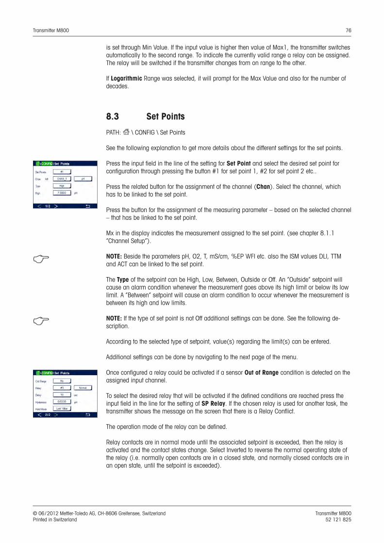
Transmitter M800 76
© 06 / 2012 Mettler-Toledo AG, CH-8606 Greifensee, Switzerland Transmitter M800 Printed in Switzerland 52 121 825
is set through Min Value. If the input value is higher then value of Max1, the transmitter switches automatically to the second range. To indicate the currently valid range a relay can be assigned. The relay will be switched if the transmitter changes from on range to the other.
If Logarithmic Range was selected, it will prompt for the Max Value and also for the number of decades.
8.3 Set Points
PATH: H \ CONFIG \ Set Points
See the following explanation to get more details about the different settings for the set points.
Press the input field in the line of the setting for Set Point and select the desired set point for configuration through pressing the button #1 for set point 1, #2 for set point 2 etc..
Press the related button for the assignment of the channel (Chan). Select the channel, which has to be linked to the set point.
Press the button for the assignment of the measuring parameter – based on the selected channel – that has be linked to the set point.
Mx in the display indicates the measurement assigned to the set point. (see chapter 8.1.1 “Channel Setup”).
h NOTE: Beside the parameters pH, O2, T, mS/cm, %EP WFI etc. also the ISM values DLI, TTM and ACT can be linked to the set point.
The Type of the setpoint can be High, Low, Between, Outside or Off. An ”Outside” setpoint will cause an alarm condition whenever the measurement goes above its high limit or below its low limit. A ”Between” setpoint will cause an alarm condition to occur whenever the measurement is between its high and low limits.
h NOTE: If the type of set point is not Off additional settings can be done. See the following de-scription.
According to the selected type of setpoint, value(s) regarding the limit(s) can be entered.
Additional settings can be done by navigating to the next page of the menu.
Once configured a relay could be activated if a sensor Out of Range condition is detected on the assigned input channel.
To select the desired relay that will be activated if the defined conditions are reached press the input field in the line for the setting of SP Relay. If the chosen relay is used for another task, the transmitter shows the message on the screen that there is a Relay Conflict.
The operation mode of the relay can be defined.
Relay contacts are in normal mode until the associated setpoint is exceeded, then the relay is activated and the contact states change. Select Inverted to reverse the normal operating state of the relay (i.e. normally open contacts are in a closed state, and normally closed contacts are in an open state, until the setpoint is exceeded).
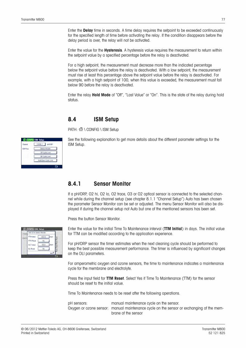
Transmitter M800 77
© 06 / 2012 Mettler-Toledo AG, CH-8606 Greifensee, Switzerland Transmitter M800 Printed in Switzerland 52 121 825
Enter the Delay time in seconds. A time delay requires the setpoint to be exceeded continuously for the specified length of time before activating the relay. If the condition disappears before the delay period is over, the relay will not be activated.
Enter the value for the Hysteresis. A hysteresis value requires the measurement to return within the setpoint value by a specified percentage before the relay is deactivated.
For a high setpoint, the measurement must decrease more than the indicated percentage below the setpoint value before the relay is deactivated. With a low setpoint, the measurement must rise at least this percentage above the setpoint value before the relay is deactivated. For example, with a high setpoint of 100, when this value is exceeded, the measurement must fall below 90 before the relay is deactivated.
Enter the relay Hold Mode of ”Off”, ”Last Value” or ”On”. This is the state of the relay during hold status.
8.4 ISM Setup
PATH: H \ CONFIG \ ISM Setup
See the following explanation to get more details about the different parameter settings for the ISM Setup.
8.4.1 Sensor Monitor
If a pH/ORP, O2 hi, O2 lo, O2 trace, O3 or O2 optical sensor is connected to the selected chan-nel while during the channel setup (see chapter 8.1.1 “Channel Setup”) Auto has been chosen the parameter Sensor Monitor can be set or adjusted. The menu Sensor Monitor will also be dis-played if during the channel setup not Auto but one of the mentioned sensors has been set.
Press the button Sensor Monitor.
Enter the value for the initial Time To Maintenance interval (TTM Initial) in days. The initial value for TTM can be modified according to the application experience.
For pH/ORP sensor the timer estimates when the next cleaning cycle should be performed to keep the best possible measurement performance. The timer is influenced by significant changes on the DLI parameters.
For amperometric oxygen and ozone sensors, the time to maintenance indicates a maintenance cycle for the membrane and electrolyte.
Press the input field for TTM Reset. Select Yes if Time To Maintenance (TTM) for the sensor should be reset to the initial value.
Time To Maintenance needs to be reset after the following operations.
pH sensors: manual maintenance cycle on the sensor. Oxygen or ozone sensor: manual maintenance cycle on the sensor or exchanging of the mem-
brane of the sensor
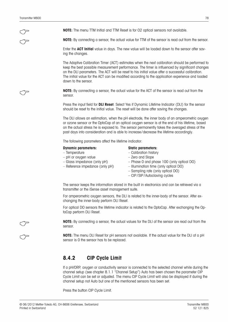
Transmitter M800 78
© 06 / 2012 Mettler-Toledo AG, CH-8606 Greifensee, Switzerland Transmitter M800 Printed in Switzerland 52 121 825
h NOTE: The menu TTM Initial and TTM Reset is for O2 optical sensors not available.
h NOTE: By connecting a sensor, the actual value for TTM of the sensor is read out from the sensor.
Enter the ACT Initial value in days. The new value will be loaded down to the sensor after sav-ing the changes.
The Adaptive Calibration Timer (ACT) estimates when the next calibration should be performed to keep the best possible measurement performance. The timer is influenced by significant changes on the DLI parameters. The ACT will be reset to his initial value after a successful calibration. The initial value for the ACT can be modified according to the application experience and loaded down to the sensor.
h NOTE: By connecting a sensor, the actual value for the ACT of the sensor is read out from the sensor.
Press the input field for DLI Reset. Select Yes if Dynamic Lifetime Indicator (DLI) for the sensor should be reset to the initial value. The reset will be done after saving the changes.
The DLI allows an estimation, when the pH electrode, the inner body of an amperometric oxygen or ozone sensor or the OptoCap of an optical oxygen sensor is at the end of his lifetime, based on the actual stress he is exposed to. The sensor permanently takes the averaged stress of the past days into consideration and is able to increase / decrease the lifetime accordingly.
The following parameters affect the lifetime indicator:
Dynamic parameters: Static parameters:– Temperature – Calibration history– pH or oxygen value – Zero and Slope – Glass impedance (only pH) – Phase 0 and phase 100 (only optical DO)– Reference impedance (only pH) – Illumination time (only optical DO) – Sampling rate (only optical DO) – CIP / SIP / Autoclaving cycles
The sensor keeps the information stored in the built in electronics and can be retrieved via a transmitter or the iSense asset management suite.
For amperometric oxygen sensors, the DLI is related to the inner-body of the sensor. After ex-changing the inner-body perform DLI Reset.
For optical DO sensors the lifetime indicator is related to the OptoCap. After exchanging the Op-toCap perform DLI Reset.
h NOTE: By connecting a sensor, the actual values for the DLI of the sensor are read out from the sensor.
h NOTE: The menu DLI Reset for pH sensors not available. If the actual value for the DLI of a pH sensor is 0 the sensor has to be replaced.
8.4.2 CIP Cycle Limit
If a pH/ORP, oxygen or conductivity sensor is connected to the selected channel while during the channel setup (see chapter 8.1.1 “Channel Setup”) Auto has been chosen the parameter CIP Cycle Limit can be set or adjusted. The menu CIP Cycle Limit will also be displayed if during the channel setup not Auto but one of the mentioned sensors has been set.
Press the button CIP Cycle Limit.
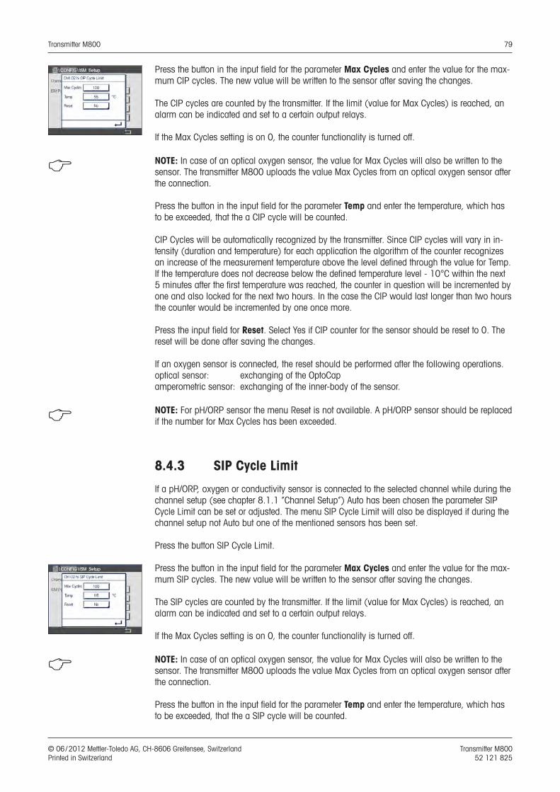
Transmitter M800 79
© 06 / 2012 Mettler-Toledo AG, CH-8606 Greifensee, Switzerland Transmitter M800 Printed in Switzerland 52 121 825
Press the button in the input field for the parameter Max Cycles and enter the value for the max-mum CIP cycles. The new value will be written to the sensor after saving the changes.
The CIP cycles are counted by the transmitter. If the limit (value for Max Cycles) is reached, an alarm can be indicated and set to a certain output relays.
If the Max Cycles setting is on 0, the counter functionality is turned off.
h NOTE: In case of an optical oxygen sensor, the value for Max Cycles will also be written to the sensor. The transmitter M800 uploads the value Max Cycles from an optical oxygen sensor after the connection.
Press the button in the input field for the parameter Temp and enter the temperature, which has to be exceeded, that the a CIP cycle will be counted.
CIP Cycles will be automatically recognized by the transmitter. Since CIP cycles will vary in in-tensity (duration and temperature) for each application the algorithm of the counter recognizes an increase of the measurement temperature above the level defined through the value for Temp. If the temperature does not decrease below the defined temperature level - 10°C within the next 5 minutes after the first temperature was reached, the counter in question will be incremented by one and also locked for the next two hours. In the case the CIP would last longer than two hours the counter would be incremented by one once more.
Press the input field for Reset. Select Yes if CIP counter for the sensor should be reset to 0. The reset will be done after saving the changes.
If an oxygen sensor is connected, the reset should be performed after the following operations.optical sensor: exchanging of the OptoCap amperometric sensor: exchanging of the inner-body of the sensor.
h NOTE: For pH/ORP sensor the menu Reset is not available. A pH/ORP sensor should be replaced if the number for Max Cycles has been exceeded.
8.4.3 SIP Cycle Limit
If a pH/ORP, oxygen or conductivity sensor is connected to the selected channel while during the channel setup (see chapter 8.1.1 “Channel Setup”) Auto has been chosen the parameter SIP Cycle Limit can be set or adjusted. The menu SIP Cycle Limit will also be displayed if during the channel setup not Auto but one of the mentioned sensors has been set.
Press the button SIP Cycle Limit.
Press the button in the input field for the parameter Max Cycles and enter the value for the max-mum SIP cycles. The new value will be written to the sensor after saving the changes.
The SIP cycles are counted by the transmitter. If the limit (value for Max Cycles) is reached, an alarm can be indicated and set to a certain output relays.
If the Max Cycles setting is on 0, the counter functionality is turned off.
h NOTE: In case of an optical oxygen sensor, the value for Max Cycles will also be written to the sensor. The transmitter M800 uploads the value Max Cycles from an optical oxygen sensor after the connection.
Press the button in the input field for the parameter Temp and enter the temperature, which has to be exceeded, that the a SIP cycle will be counted.
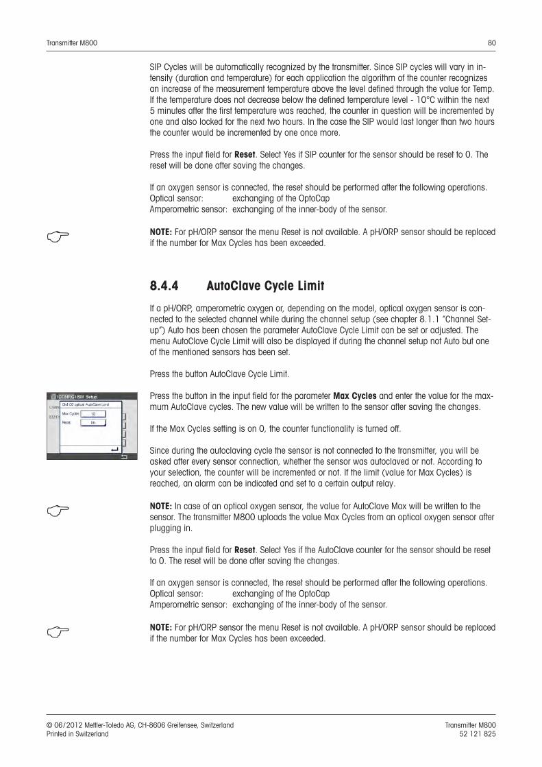
Transmitter M800 80
© 06 / 2012 Mettler-Toledo AG, CH-8606 Greifensee, Switzerland Transmitter M800 Printed in Switzerland 52 121 825
SIP Cycles will be automatically recognized by the transmitter. Since SIP cycles will vary in in-tensity (duration and temperature) for each application the algorithm of the counter recognizes an increase of the measurement temperature above the level defined through the value for Temp. If the temperature does not decrease below the defined temperature level - 10°C within the next 5 minutes after the first temperature was reached, the counter in question will be incremented by one and also locked for the next two hours. In the case the SIP would last longer than two hours the counter would be incremented by one once more.
Press the input field for Reset. Select Yes if SIP counter for the sensor should be reset to 0. The reset will be done after saving the changes.
If an oxygen sensor is connected, the reset should be performed after the following operations. Optical sensor: exchanging of the OptoCap Amperometric sensor: exchanging of the inner-body of the sensor.
h NOTE: For pH/ORP sensor the menu Reset is not available. A pH/ORP sensor should be replaced if the number for Max Cycles has been exceeded.
8.4.4 AutoClave Cycle Limit
If a pH/ORP, amperometric oxygen or, depending on the model, optical oxygen sensor is con-nected to the selected channel while during the channel setup (see chapter 8.1.1 “Channel Set-up”) Auto has been chosen the parameter AutoClave Cycle Limit can be set or adjusted. The menu AutoClave Cycle Limit will also be displayed if during the channel setup not Auto but one of the mentioned sensors has been set.
Press the button AutoClave Cycle Limit.
Press the button in the input field for the parameter Max Cycles and enter the value for the max-mum AutoClave cycles. The new value will be written to the sensor after saving the changes.
If the Max Cycles setting is on 0, the counter functionality is turned off.
Since during the autoclaving cycle the sensor is not connected to the transmitter, you will be asked after every sensor connection, whether the sensor was autoclaved or not. According to your selection, the counter will be incremented or not. If the limit (value for Max Cycles) is reached, an alarm can be indicated and set to a certain output relay.
h NOTE: In case of an optical oxygen sensor, the value for AutoClave Max will be written to the sensor. The transmitter M800 uploads the value Max Cycles from an optical oxygen sensor after plugging in.
Press the input field for Reset. Select Yes if the AutoClave counter for the sensor should be reset to 0. The reset will be done after saving the changes.
If an oxygen sensor is connected, the reset should be performed after the following operations. Optical sensor: exchanging of the OptoCap Amperometric sensor: exchanging of the inner-body of the sensor.
h NOTE: For pH/ORP sensor the menu Reset is not available. A pH/ORP sensor should be replaced if the number for Max Cycles has been exceeded.
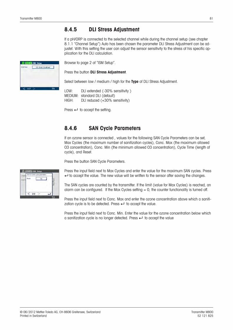
Transmitter M800 81
© 06 / 2012 Mettler-Toledo AG, CH-8606 Greifensee, Switzerland Transmitter M800 Printed in Switzerland 52 121 825
8.4.5 DLI Stress Adjustment
If a pH/ORP is connected to the selected channel while during the channel setup (see chapter 8.1.1 “Channel Setup”) Auto has been chosen the parameter DLI Stress Adjustment can be ad-justet. With this setting the user can adjust the sensor sensitivity to the stress of his specific ap-plication for the DLI calculation.
Browse to page 2 of “ISM Setup”.
Press the button DLI Stress Adjustment.
Select between low / medium / high for the Type of DLI Stress Adjustment.
LOW: DLI extended (-30% sensitivity )MEDIUM: standard DLI (default)HIGH: DLI reduced (+30% sensitivity)
Press e to accept the setting.
8.4.6 SAN Cycle Parameters
If an ozone sensor is connected , values for the following SAN Cycle Parameters can be set, Max Cycles (the maximum number of sanitization cycles), Conc. Max (the maximum allowed O3 concentration), Conc. Min (the minimum allowed O3 concentration), Cycle Time (length of cycle), and Reset.
Press the button SAN Cycle Parameters.
Press the input field next to Max Cycles and enter the value for the maximum SAN cycles. Press e to accept the value. The new value will be written to the sensor after saving the changes.
The SAN cycles are counted by the transmitter. If the limit (value for Max Cycles) is reached, an alarm can be configured. If the Max Cycles setting = 0, the counter functionality is turned off.
Press the input field next to Conc. Max and enter the ozone concentration above which a saniti-zation cycle is to be detected. Press e to accept the value.
Press the input field next to Conc. Min. Enter the value for the ozone concentration below which a sanitization cycle is no longer detected. Press e to accept the value
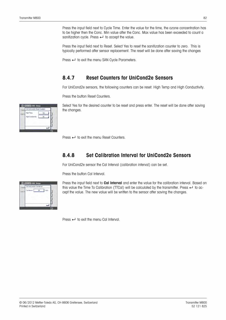
Transmitter M800 82
© 06 / 2012 Mettler-Toledo AG, CH-8606 Greifensee, Switzerland Transmitter M800 Printed in Switzerland 52 121 825
Press the input field next to Cycle Time. Enter the value for the time, the ozone concentration has to be higher then the Conc. Min value after the Conc. Max value has been exceeded to count a sanitization cycle. Press e to accept the value.
Press the input field next to Reset. Select Yes to reset the sanitization counter to zero. This is typically performed after sensor replacement. The reset will be done after saving the changes
Press e to exit the menu SAN Cycle Parameters.
8.4.7 Reset Counters for UniCond2e Sensors
For UniCond2e sensors, the following counters can be reset: High Temp and High Conductivity.
Press the button Reset Counters.
Select Yes for the desired counter to be reset and press enter. The reset will be done after saving the changes.
Press e to exit the menu Reset Counters.
8.4.8 Set Calibration Interval for UniCond2e Sensors
For UniCond2e sensor the Cal Interval (calibration interval) can be set.
Press the button Cal Interval.
Press the input field next to Cal Interval and enter the value for the calibration interval. Based on this value the Time To Calibration (TTCal) will be calculated by the transmitter. Press e to ac-cept the value. The new value will be written to the sensor after saving the changes.
Press e to exit the menu Cal Interval.
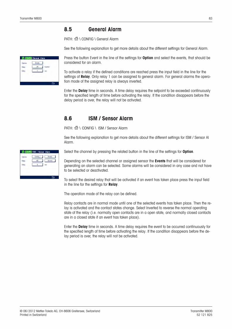
Transmitter M800 83
© 06 / 2012 Mettler-Toledo AG, CH-8606 Greifensee, Switzerland Transmitter M800 Printed in Switzerland 52 121 825
8.5 General Alarm
PATH: H \ CONFIG \ General Alarm
See the following explanation to get more details about the different settings for General Alarm.
Press the button Event in the line of the settings for Option and select the events, that should be considered for an alarm.
To activate a relay if the defined conditions are reached press the input field in the line for the settings of Relay. Only relay 1 can be assigned to general alarm. For general alarms the opera-tion mode of the assigned relay is always inverted.
Enter the Delay time in seconds. A time delay requires the setpoint to be exceeded continuously for the specified length of time before activating the relay. If the condition disappears before the delay period is over, the relay will not be activated.
8.6 ISM / Sensor Alarm
PATH: H \ CONFIG \ ISM / Sensor Alarm
See the following explanation to get more details about the different settings for ISM / Sensor Al Alarm.
Select the channel by pressing the related button in the line of the settings for Option.
Depending on the selected channel or assigned sensor the Events that will be considered for generating an alarm can be selected. Some alarms will be considered in any case and not have to be selected or deactivated.
To select the desired relay that will be activated if an event has taken place press the input field in the line for the settings for Relay.
The operation mode of the relay can be defined.
Relay contacts are in normal mode until one of the selected events has taken place. Then the re-lay is activated and the contact states change. Select Inverted to reverse the normal operating state of the relay (i.e. normally open contacts are in a open state, and normally closed contacts are in a closed state if an event has taken place).
Enter the Delay time in seconds. A time delay requires the event to be occurred continuously for the specified length of time before activating the relay. If the condition disappears before the de-lay period is over, the relay will not be activated.
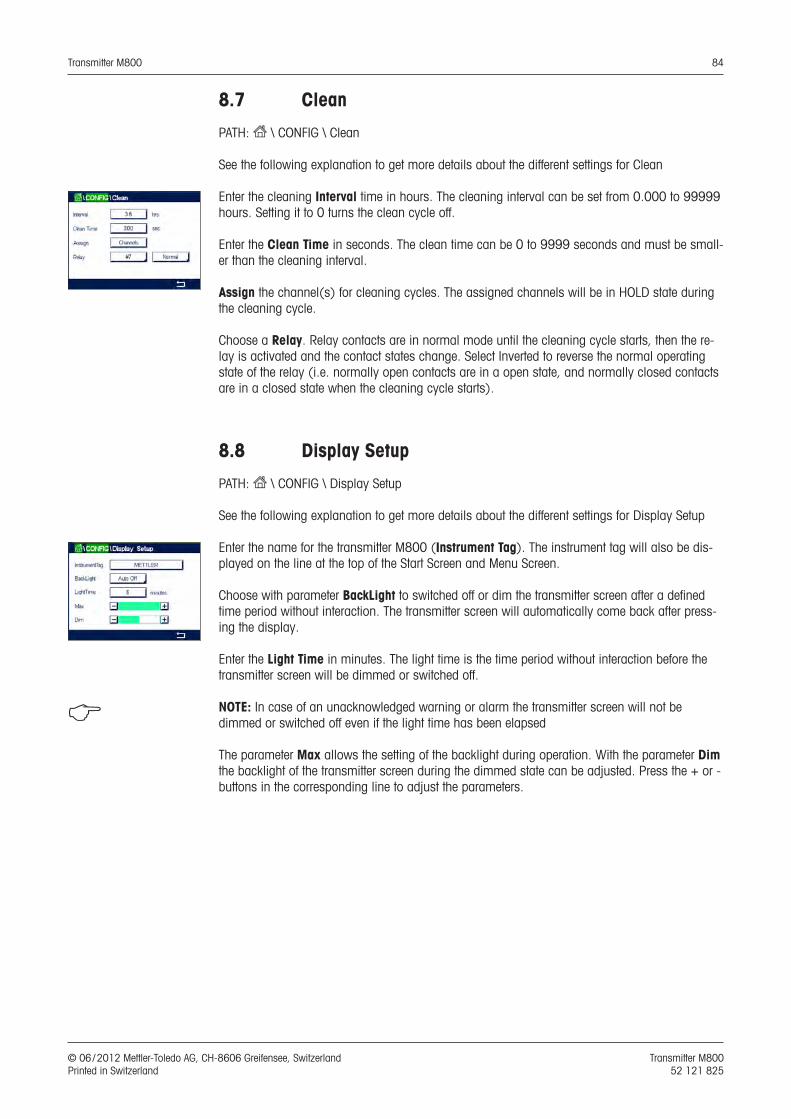
Transmitter M800 84
© 06 / 2012 Mettler-Toledo AG, CH-8606 Greifensee, Switzerland Transmitter M800 Printed in Switzerland 52 121 825
8.7 Clean
PATH: H \ CONFIG \ Clean
See the following explanation to get more details about the different settings for Clean
Enter the cleaning Interval time in hours. The cleaning interval can be set from 0.000 to 99999 hours. Setting it to 0 turns the clean cycle off.
Enter the Clean Time in seconds. The clean time can be 0 to 9999 seconds and must be small-er than the cleaning interval.
Assign the channel(s) for cleaning cycles. The assigned channels will be in HOLD state during the cleaning cycle.
Choose a Relay. Relay contacts are in normal mode until the cleaning cycle starts, then the re-lay is activated and the contact states change. Select Inverted to reverse the normal operating state of the relay (i.e. normally open contacts are in a open state, and normally closed contacts are in a closed state when the cleaning cycle starts).
8.8 Display Setup
PATH: H \ CONFIG \ Display Setup
See the following explanation to get more details about the different settings for Display Setup
Enter the name for the transmitter M800 (Instrument Tag). The instrument tag will also be dis-played on the line at the top of the Start Screen and Menu Screen.
Choose with parameter BackLight to switched off or dim the transmitter screen after a defined time period without interaction. The transmitter screen will automatically come back after press-ing the display.
Enter the Light Time in minutes. The light time is the time period without interaction before the transmitter screen will be dimmed or switched off.
h NOTE: In case of an unacknowledged warning or alarm the transmitter screen will not be dimmed or switched off even if the light time has been elapsed
The parameter Max allows the setting of the backlight during operation. With the parameter Dim the backlight of the transmitter screen during the dimmed state can be adjusted. Press the + or - buttons in the corresponding line to adjust the parameters.
Transmitter M800 85
© 06 / 2012 Mettler-Toledo AG, CH-8606 Greifensee, Switzerland Transmitter M800 Printed in Switzerland 52 121 825
8.9 Digital Inputs
PATH: H \ CONFIG \ Digital Inputs
See the following explanation to get more details about the different settings for the digital inputs
Press the related button for the assignment of the Channel (Chan_). Select the channel, which has to be linked to the digital input signal.
Press the input field in the line of the setting for Mode and select the impact of an active digital input signal. Choose ‘Hold’ to lead the assigned channel in hold state. For flow sensor the digi-tal input signal can be used to reset the totalized flow value (Reset T-flow) for the channel. If an optical DO sensors is connected, the digital input signal can be used for LED controlling.
Press the related button for the assignment of the Digital Inputs (#1 for DI1, #2 for DI2 etc.) and select the digital input signal, which has to be linked to the channel.
An additional setting can be done, it an digital input signal has been selected.
Press the input field in the line for the setting of the State and select if the digital input is active at high or low level of the voltage input signal.
8.10 System
PATH: H \ CONFIG \ System
See the following explanation to get more details about the different settings for the System.
Select the desired Language. The following languages are available: English, French, German, Italian, Spanish, Portuguese, Russian, Chinese, Korean or Japanese.
Enter Date&Time.
The automatic change-over from summertime to wintertime and vice-versa frees the users from having to correct the time twice a year.
The winter to summer time-change are carried out automatically using the 12-month clock inte-grated in the transmitter. The date for the time-change can be set with the parameter Summer.
Provided it is a Sunday, the time-change would take place on the day that equates with the val-ue, otherwise on the following Sunday. The winter/summer time-change takes place at 02:00 h.
The summer to winter time-change are carried out automatically using the 12-month clock inte-grated in the transmitter. The date for the time-change can be set through the parameter Winter.
Provided it is a Sunday, the time-change would take place on the day that equates with the val-ue, otherwise on the following Sunday. The winter/summer time-change takes place at 03:00 h.
The number of hours, the clock will be shifted through the winter to summer and summer to winter time-change can be chosen. Press the related button for the setting of the Shift Hour.
Transmitter M800 86
© 06 / 2012 Mettler-Toledo AG, CH-8606 Greifensee, Switzerland Transmitter M800 Printed in Switzerland 52 121 825
8.11 PID Controller
PATH: H \ CONFIG \ PID Controller
PID control is proportional, integral and derivative control action that can provide smooth regula-tion of a process. Before configuring the transmitter, the following process characteristics must be identified.
Identify the control direction of the process– Conductivity: Dilution – direct acting where increasing measurement produces increasing control output
such as controlling the feed of low conductivity diluting water to rinse tanks, cooling towers or boilers
Concentrating – reverse acting where increasing measurement produces decreasing control output, such as controlling chemical feed to attain a desired concentration
– Dissolved Oxygen: Deaeration – direct acting where increasing DO concentration produces increasing control out-
put such as controlling the feed of a reducing agent to remove oxygen from boiler feedwater Aeration – reverse acting where increasing DO concentration produces decreasing control
output, such as controlling an aerator blower speed to maintain a desired DO concentration in fermentation or wastewater treatment
– pH / ORP: Acid feed only – direct acting where increasing pH produces increasing control output,
also for ORP reducing reagent feed Base feed only – reverse acting where increasing pH produces decreasing control output,
also for ORP oxidizing reagent feed Both acid and base feed – direct and reverse acting
Identify the control output type based on the control device to be used: Pulse frequency – used with pulse input metering pump Pulse length – used with solenoid valve Analog – used with current input device such as electric drive unit, analog input metering
pump or current-to-pneumatic (I / P) converter for pneumatic control valve
Default control settings provide linear control, which is appropriate for conductivity, dissolved oxygen. Therefore, when configuring PID for these parameters (or simple pH control) ignore set-tings of deadband and corner points in the tuning parameter section below. The non-linear con-trol settings are used for more difficult pH / ORP control situations.
If desired, identify the non-linearity of the pH / ORP process. Improved control can be obtained if the non-linearity is accommodated with an opposing non-linearity in the controller. A titration curve (graph of pH or ORP vs. reagent volume) made on a process sample provides the best information. There is often a very high process gain or sensitivity near the setpoint and de-creasing gain further away from the setpoint. To counteract this, the instrument allows for adjust-able non-linear control with settings of a deadband around the setpoint, corner points further out and proportional limits at the ends of control as shown in the figure below.
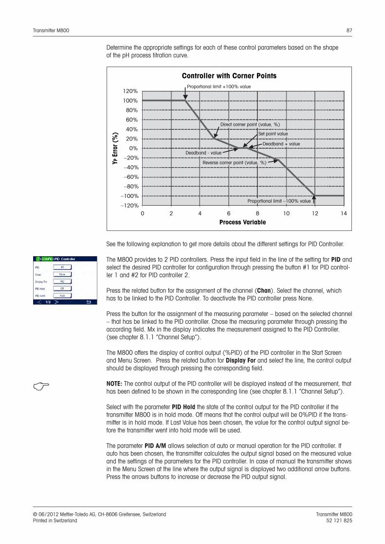
Transmitter M800 87
© 06 / 2012 Mettler-Toledo AG, CH-8606 Greifensee, Switzerland Transmitter M800 Printed in Switzerland 52 121 825
Determine the appropriate settings for each of these control parameters based on the shape of the pH process titration curve.
Controller with Corner Points
–120%
–100%
–80%
–60%
–40%
–20%
0%
20%
40%
60%
80%
100%
120%
0 2 4 6 8 10 12 14
Process Variable
Deadband - value
Proportional limit –100% value
Proportional limit +100% value
YP E
rror (
%)
Direct corner point (value, %)
Set point value
Deadband + value
Reverse corner point (value, %)
See the following explanation to get more details about the different settings for PID Controller.
The M800 provides to 2 PID controllers. Press the input field in the line of the setting for PID and select the desired PID controller for configuration through pressing the button #1 for PID control-ler 1 and #2 for PID controller 2.
Press the related button for the assignment of the channel (Chan). Select the channel, which has to be linked to the PID Controller. To deactivate the PID controller press None.
Press the button for the assignment of the measuring parameter – based on the selected channel – that has be linked to the PID controller. Chose the measuring parameter through pressing the according field. Mx in the display indicates the measurement assigned to the PID Controller. (see chapter 8.1.1 “Channel Setup”).
The M800 offers the display of control output (%PID) of the PID controller in the Start Screen and Menu Screen. Press the related button for Display For and select the line, the control output should be displayed through pressing the corresponding field.
h NOTE: The control output of the PID controller will be displayed instead of the measurement, that has been defined to be shown in the corresponding line (see chapter 8.1.1 “Channel Setup”).
Select with the parameter PID Hold the state of the control output for the PID controller if the transmitter M800 is in hold mode. Off means that the control output will be 0%PID if the trans-mitter is in hold mode. If Last Value has been chosen, the value for the control output signal be-fore the transmitter went into hold mode will be used.
The parameter PID A/M allows selection of auto or manual operation for the PID controller. If auto has been chosen, the transmitter calculates the output signal based on the measured value and the settings of the parameters for the PID controller. In case of manual the transmitter shows in the Menu Screen at the line where the output signal is displayed two additional arrow buttons. Press the arrows buttons to increase or decrease the PID output signal.
Transmitter M800 88
© 06 / 2012 Mettler-Toledo AG, CH-8606 Greifensee, Switzerland Transmitter M800 Printed in Switzerland 52 121 825
h NOTE: If Manual has been chosen the values for the time constants, gain, corner points, propor-tional limits, setpoint and deadband do not have any influence on the output signal.
Additional settings can be done by navigating to the next page of the menu.
The PID Mode assigns a relay or analog output for PID control action. Based on the control de-vice being used, select one of the three options Relay PL, Relay PF and Aout through pressing the corresponding field
Relay PL: If using a solenoid valve, select Relays PL (Pulse Length). Relay PF: If using a pulse input metering pump, select Relays PF (Pulse Frequency)Aout: For using an analog control select Aout.
Link the output signal Out1,2 of the PID controller to the desired output of the transmitter. Press the related button for Out 1 and Out 2 and select the corresponding number for the output through pressing the according field. #1 means relay 1 or Aout 1, #2 means relay 2 our Aout 2 etc.
h NOTE: Take care if reed type relays are linked to the controlling function. The reed type relays could be used for pulse frequency control devices and light duty applications. The current is lim-ited to 0.5 amps and 10 watts (see also chapter 14.2 ”Electrical Specifications”). Do not con-nect to this relays higher current devices.
If the PID Mode is set to Relay PL, the Puls Length for the output signal of the transmitter can be adjusted. Press the button for Pulse Length and the M800 displays a keypad for modifying the value. Enter the new value in the unit seconds according to the table below and press e.
h NOTE: A longer pulse length will reduce wear on the solenoid valve. The % “on” time in the cy-cle is proportional to the control output.
1st Relay Position(Out 1)
2nd Relay Position (Out 2)
Pulse Length (PL)
ConductivityControlling concentrating reagent feed
Controlling dilution water
Short (PL) provides more uniform feed. Suggested start point = 30 sec
pH / ORP Feeding base Feeding acid
Reagent addition cycle: short PL provides more uniform addition of reagent. Suggested start point = 10 sec
Dissolved Oxygen
Reverse control action
Direct acting control action
Feed cycle time: short PL provides more uniform feed. Suggested start point = 30 sec
If the PID Mode is set to Relay PF, the Puls Frequency for the output signal of the transmitter can be adjusted. Press the button for Pulse Freq and enter the new value in the unit pulse / minute according to the table below.
h NOTE: Set the pulse frequency to the maximum frequency allowed for the particular pump being used, typically 60 to 100 pulses / minute. Control action will produce this frequency at 100% output.
a CAUTION: Setting the pulse frequency too high may cause the pump to overheat.
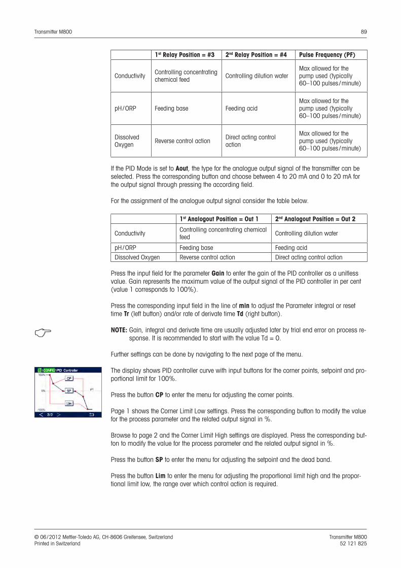
Transmitter M800 89
© 06 / 2012 Mettler-Toledo AG, CH-8606 Greifensee, Switzerland Transmitter M800 Printed in Switzerland 52 121 825
1st Relay Position = #3 2nd Relay Position = #4 Pulse Frequency (PF)
Conductivity Controlling concentrating chemical feed Controlling dilution water
Max allowed for the pump used (typically 60–100 pulses / minute)
pH / ORP Feeding base Feeding acidMax allowed for the pump used (typically 60–100 pulses / minute)
Dissolved Oxygen Reverse control action Direct acting control
action
Max allowed for the pump used (typically 60–100 pulses / minute)
If the PID Mode is set to Aout, the type for the analogue output signal of the transmitter can be selected. Press the corresponding button and choose between 4 to 20 mA and 0 to 20 mA for the output signal through pressing the according field.
For the assignment of the analogue output signal consider the table below.
1st Analogout Position = Out 1 2nd Analogout Position = Out 2
Conductivity Controlling concentrating chemical feed Controlling dilution water
pH / ORP Feeding base Feeding acid
Dissolved Oxygen Reverse control action Direct acting control action
Press the input field for the parameter Gain to enter the gain of the PID controller as a unitless value. Gain represents the maximum value of the output signal of the PID controller in per cent (value 1 corresponds to 100%).
Press the corresponding input field in the line of min to adjust the Parameter integral or reset time Tr (left button) and/or rate of derivate time Td (right button).
h NOTE: Gain, integral and derivate time are usually adjusted later by trial end error on process re-sponse. It is recommended to start with the value Td = 0.
Further settings can be done by navigating to the next page of the menu.
The display shows PID controller curve with input buttons for the corner points, setpoint and pro-portional limit for 100%.
Press the button CP to enter the menu for adjusting the corner points.
Page 1 shows the Corner Limit Low settings. Press the corresponding button to modify the value for the process parameter and the related output signal in %.
Browse to page 2 and the Corner Limit High settings are displayed. Press the corresponding but-ton to modify the value for the process parameter and the related output signal in %.
Press the button SP to enter the menu for adjusting the setpoint and the dead band.
Press the button Lim to enter the menu for adjusting the proportional limit high and the propor-tional limit low, the range over which control action is required.

Transmitter M800 90
© 06 / 2012 Mettler-Toledo AG, CH-8606 Greifensee, Switzerland Transmitter M800 Printed in Switzerland 52 121 825
8.12 Service
PATH: H \ CONFIG \ Service
This menu is a valuable tool for troubleshooting and provides diagnostic functionality for the fol-lowing items: Calibrate TouchPad, Set Analog Outputs, Read Analog Outputs, Read Analog In-puts, Set Relays, Read Relays, Read Digital Inputs, Memory, Display and optical DO sensors.
Select through the paramenter System the desired item for diagnostic by pressing the according field.
Select through Chan the channel for diagnostic information of the optical DO sensor. This menu is only displayed if an optical DO sensor is connected.
The provided diagnostic functionality can now be called up through pressing the button Diag-nostic.
8.12.1 Set Analog Outputs
The menu enables the user to set all analog outputs to any mA value within the 0–22 mA range. Use the + and – button to adjust the mA output signal. The transmitter will adjust the output sig-nals according to the measurement and configuration of the analog output signals.
8.12.2 Read Analog Outputs
The menu shows the mA value of the analog outputs.
8.12.3 Read Analog Inputs
The menu shows the mA value of the analog input signals.
8.12.4 Set Relay
The menu allows the user to open or close each relay manually. If the menu will be exited, the transmitter will switch the relay according configuration.
8.12.5 Read Relay
The menu shows state of every relay. On indicates the relay is closed, Off indicates that the relay is open.
8.12.6 Read Digital Inputs
The menu shows the state of the digital input signals.
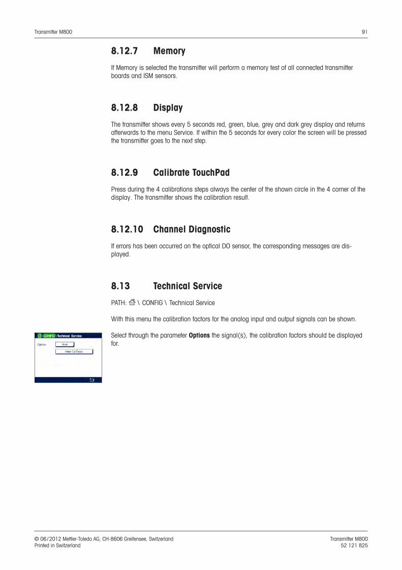
Transmitter M800 91
© 06 / 2012 Mettler-Toledo AG, CH-8606 Greifensee, Switzerland Transmitter M800 Printed in Switzerland 52 121 825
8.12.7 Memory
If Memory is selected the transmitter will perform a memory test of all connected transmitter boards and ISM sensors.
8.12.8 Display
The transmitter shows every 5 seconds red, green, blue, grey and dark grey display and returns afterwards to the menu Service. If within the 5 seconds for every color the screen will be pressed the transmitter goes to the next step.
8.12.9 Calibrate TouchPad
Press during the 4 calibrations steps always the center of the shown circle in the 4 corner of the display. The transmitter shows the calibration result.
8.12.10 Channel Diagnostic
If errors has been occurred on the optical DO sensor, the corresponding messages are dis-played.
8.13 Technical Service
PATH: H \ CONFIG \ Technical Service
With this menu the calibration factors for the analog input and output signals can be shown.
Select through the parameter Options the signal(s), the calibration factors should be displayed for.
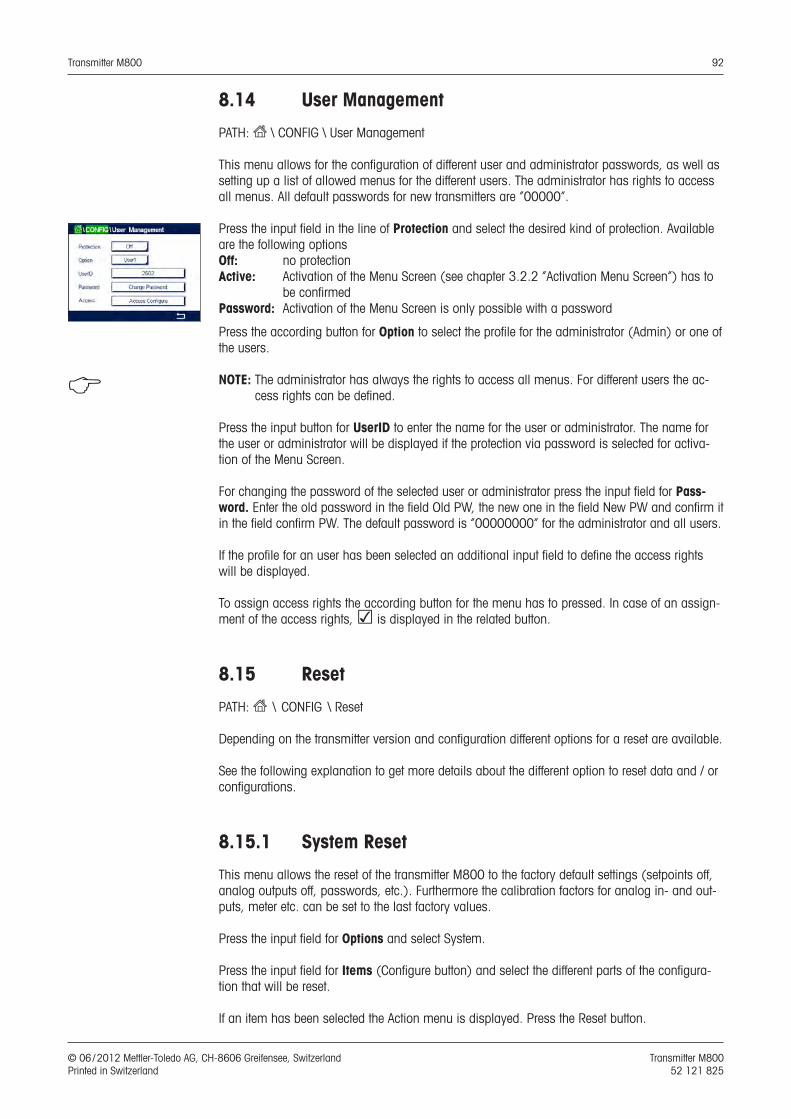
Transmitter M800 92
© 06 / 2012 Mettler-Toledo AG, CH-8606 Greifensee, Switzerland Transmitter M800 Printed in Switzerland 52 121 825
8.14 User Management
PATH: H \ CONFIG \ User Management
This menu allows for the configuration of different user and administrator passwords, as well as setting up a list of allowed menus for the different users. The administrator has rights to access all menus. All default passwords for new transmitters are ”00000”.
Press the input field in the line of Protection and select the desired kind of protection. Available are the following optionsOff: no protectionActive: Activation of the Menu Screen (see chapter 3.2.2 ”Activation Menu Screen”) has to
be confirmedPassword: Activation of the Menu Screen is only possible with a password
Press the according button for Option to select the profile for the administrator (Admin) or one of the users.
h NOTE: The administrator has always the rights to access all menus. For different users the ac-cess rights can be defined.
Press the input button for UserID to enter the name for the user or administrator. The name for the user or administrator will be displayed if the protection via password is selected for activa-tion of the Menu Screen.
For changing the password of the selected user or administrator press the input field for Pass-word. Enter the old password in the field Old PW, the new one in the field New PW and confirm it in the field confirm PW. The default password is “00000000” for the administrator and all users.
If the profile for an user has been selected an additional input field to define the access rights will be displayed.
To assign access rights the according button for the menu has to pressed. In case of an assign-ment of the access rights, ☑ is displayed in the related button.
8.15 Reset
PATH: H \ CONFIG \ Reset
Depending on the transmitter version and configuration different options for a reset are available.
See the following explanation to get more details about the different option to reset data and / or configurations.
8.15.1 System Reset
This menu allows the reset of the transmitter M800 to the factory default settings (setpoints off, analog outputs off, passwords, etc.). Furthermore the calibration factors for analog in- and out-puts, meter etc. can be set to the last factory values.
Press the input field for Options and select System.
Press the input field for Items (Configure button) and select the different parts of the configura-tion that will be reset.
If an item has been selected the Action menu is displayed. Press the Reset button.
Transmitter M800 93
© 06 / 2012 Mettler-Toledo AG, CH-8606 Greifensee, Switzerland Transmitter M800 Printed in Switzerland 52 121 825
8.15.2 Reset Sensor Calibration for Optical DO Sensors
If an optical oxygen sensor is connected to the transmitter, a menu is available that allows the reset of the calibration data of the sensor to the factory settings.
Press the input field for Options and select the channel the optical DO sensor is connected to.
Press the input field for Items (Configure button). Select SensorCal to Factory through pressing the according button.
If SensorCal to Factory has been selected the Action menu is displayed. Press the Reset button.
h NOTE: Through a reset of the calibration data the Adaptive Calibration Timer (see chapter 9.1 ”iMonitor”) will set to 0.
h NOTE: To ensure best measuring results, a new calibration of the sensor is recommended after a reset of the calibration data to factory settings. Depending on the application and sensor, the calibration should be performed as a one point calibration or two point calibration (see chapter 7.7 “Calibration of Optical Oxygen Sensors”).
8.15.3 Reset Sensor Calibration for UniCond2e Sensors
For UniCond2e sensors, the SensorCal (sensor calibration) and ElecCal (sensor electronics cal-ibration) can be restored to factory settings.
Press the input field for Options and select the channel the UniCond2e sensor is connected to.
Press the input field for Item (Configure button). Select SensorCal to Factory and/or ElecCal to Factory by checking the adjacent box. Press e enter to accept the value.
If an item has been selected the Action menu is displayed. Press the Reset button.
The M800 will bring up the confirmation dialog. Select Yes and the reset will be executed. Press No to go back to menu Reset without performing the reset.
8.15.4 Reset Total Flow
For models of the M800 transmitter that accept flow signals the totalized flow value for each channel can be reset.
Press the input field for Options and select the channel for which the totalized flow value should be reset.
Press the input field for Items (Configure button). Select Total Flow by checking the adjacent box. Press e to accept the value.
If Total Flow has been selected the Action menu is displayed. Press the Reset button.
The M800 will bring up the confirmation dialog. Select Yes and the reset will be executed. Press No to go back to menu Reset without performing the reset.
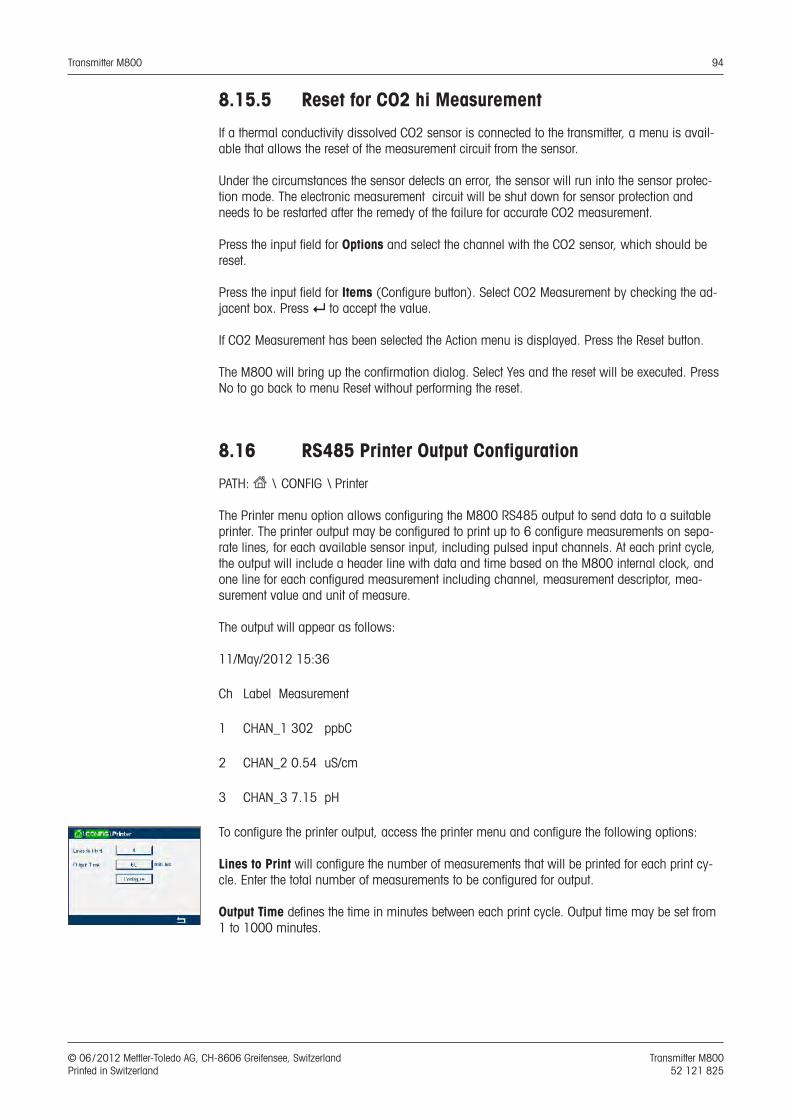
Transmitter M800 94
© 06 / 2012 Mettler-Toledo AG, CH-8606 Greifensee, Switzerland Transmitter M800 Printed in Switzerland 52 121 825
8.15.5 Reset for CO2 hi Measurement
If a thermal conductivity dissolved CO2 sensor is connected to the transmitter, a menu is avail-able that allows the reset of the measurement circuit from the sensor.
Under the circumstances the sensor detects an error, the sensor will run into the sensor protec-tion mode. The electronic measurement circuit will be shut down for sensor protection and needs to be restarted after the remedy of the failure for accurate CO2 measurement.
Press the input field for Options and select the channel with the CO2 sensor, which should be reset.
Press the input field for Items (Configure button). Select CO2 Measurement by checking the ad-jacent box. Press e to accept the value.
If CO2 Measurement has been selected the Action menu is displayed. Press the Reset button.
The M800 will bring up the confirmation dialog. Select Yes and the reset will be executed. Press No to go back to menu Reset without performing the reset.
8.16 RS485 Printer Output Configuration
PATH: H \ CONFIG \ Printer
The Printer menu option allows configuring the M800 RS485 output to send data to a suitable printer. The printer output may be configured to print up to 6 configure measurements on sepa-rate lines, for each available sensor input, including pulsed input channels. At each print cycle, the output will include a header line with data and time based on the M800 internal clock, and one line for each configured measurement including channel, measurement descriptor, mea-surement value and unit of measure.
The output will appear as follows:
11/May/2012 15:36
Ch Label Measurement
1 CHAN_1 302 ppbC
2 CHAN_2 0.54 uS/cm
3 CHAN_3 7.15 pH
To configure the printer output, access the printer menu and configure the following options:
Lines to Print will configure the number of measurements that will be printed for each print cy-cle. Enter the total number of measurements to be configured for output.
Output Time defines the time in minutes between each print cycle. Output time may be set from 1 to 1000 minutes.

Transmitter M800 95
© 06 / 2012 Mettler-Toledo AG, CH-8606 Greifensee, Switzerland Transmitter M800 Printed in Switzerland 52 121 825
Once the output time and print lines has been established, press the Configure button to format the printer output. The number at the left of the window shows the order in which the lines will appear on the printer output. From the first dropdown, select the channel with which the desired sensor is connected. This dropdown will list the labels associated with each channel as config-ured under Channel Setup. Usint the second dropdown, select the unit associated with the mea-surement to be displayed. Note that if more the 4 lines of output has been selected, use the < and > icons to navigate through the pages to be configured.
8.17 USB Measurement Interface
The user may access measurement values via the USB. The user provides a command and the M800 responds using the following format.
Command: [0x02][0x02]“Dx”(x is the channel index: 1-6) Response: “XXXXXXXXuuuuuu XXXXXXXXuuuuuu XXXXXXXXuuuuuu XXXXXXXXuuuuuu”<cr>
h NOTE: The first instance of 0x02 is the ID for M800, which must be 0x02 only. The second in-stance of 0x02 is the length, which must be 0x02 only. The response provides M1~M4 only. XXXXXXXX is measurement floating value in ASCII. uuuuuu is the unit in ASCII, if current unit is less than 6 characters, the format is right aligned, e.g. if unit is pH, response “ pH”. <cr> means carriage return (0x0D, 0x0A)
If the sending command is not correct an error message is generated.Error response format: “ERROR #xx” xx is the error code 01: Invalid opcode ---- if it is not D. 02: Parameter error ---- if x is not 1-6 07: Length error ---- if length is not 2.
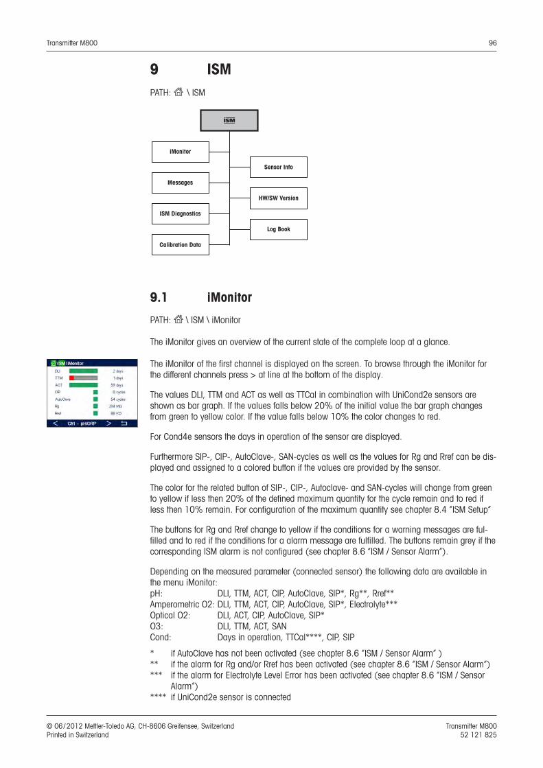
Transmitter M800 96
© 06 / 2012 Mettler-Toledo AG, CH-8606 Greifensee, Switzerland Transmitter M800 Printed in Switzerland 52 121 825
9 ISMPATH: H \ ISM
i
iMonitor
Messages
ISM Diagnostics
Calibration Data
Sensor Info
HW/SW Version
Log Book
9.1 iMonitor
PATH: H \ ISM \ iMonitor
The iMonitor gives an overview of the current state of the complete loop at a glance.
The iMonitor of the first channel is displayed on the screen. To browse through the iMonitor for the different channels press > at line at the bottom of the display.
The values DLI, TTM and ACT as well as TTCal in combination with UniCond2e sensors are shown as bar graph. If the values falls below 20% of the initial value the bar graph changes from green to yellow color. If the value falls below 10% the color changes to red.
For Cond4e sensors the days in operation of the sensor are displayed.
Furthermore SIP-, CIP-, AutoClave-, SAN-cycles as well as the values for Rg and Rref can be dis-played and assigned to a colored button if the values are provided by the sensor.
The color for the related button of SIP-, CIP-, Autoclave- and SAN-cycles will change from green to yellow if less then 20% of the defined maximum quantity for the cycle remain and to red if less then 10% remain. For configuration of the maximum quantity see chapter 8.4 “ISM Setup”
The buttons for Rg and Rref change to yellow if the conditions for a warning messages are ful-filled and to red if the conditions for a alarm message are fulfilled. The buttons remain grey if the corresponding ISM alarm is not configured (see chapter 8.6 “ISM / Sensor Alarm”).
Depending on the measured parameter (connected sensor) the following data are available in the menu iMonitor:pH: DLI, TTM, ACT, CIP, AutoClave, SIP*, Rg**, Rref**Amperometric O2: DLI, TTM, ACT, CIP, AutoClave, SIP*, Electrolyte***Optical O2: DLI, ACT, CIP, AutoClave, SIP*O3: DLI, TTM, ACT, SANCond: Days in operation, TTCal****, CIP, SIP
* if AutoClave has not been activated (see chapter 8.6 “ISM / Sensor Alarm” )** if the alarm for Rg and/or Rref has been activated (see chapter 8.6 “ISM / Sensor Alarm”)*** if the alarm for Electrolyte Level Error has been activated (see chapter 8.6 “ISM / Sensor
Alarm”)**** if UniCond2e sensor is connected
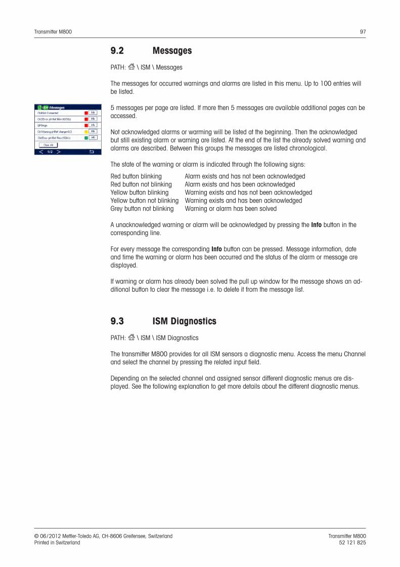
Transmitter M800 97
© 06 / 2012 Mettler-Toledo AG, CH-8606 Greifensee, Switzerland Transmitter M800 Printed in Switzerland 52 121 825
9.2 Messages
PATH: H \ ISM \ Messages
The messages for occurred warnings and alarms are listed in this menu. Up to 100 entries will be listed.
5 messages per page are listed. If more then 5 messages are available additional pages can be accessed.
Not acknowledged alarms or warming will be listed at the beginning. Then the acknowledged but still existing alarm or warning are listed. At the end of the list the already solved warning and alarms are described. Between this groups the messages are listed chronological.
The state of the warning or alarm is indicated through the following signs:
Red button blinking Alarm exists and has not been acknowledgedRed button not blinking Alarm exists and has been acknowledgedYellow button blinking Warning exists and has not been acknowledgedYellow button not blinking Warning exists and has been acknowledgedGrey button not blinking Warning or alarm has been solved
A unacknowledged warning or alarm will be acknowledged by pressing the Info button in the corresponding line.
For every message the corresponding Info button can be pressed. Message information, date and time the warning or alarm has been occurred and the status of the alarm or message are displayed.
If warning or alarm has already been solved the pull up window for the message shows an ad-ditional button to clear the message i.e. to delete it from the message list.
9.3 ISM Diagnostics
PATH: H \ ISM \ ISM Diagnostics
The transmitter M800 provides for all ISM sensors a diagnostic menu. Access the menu Channel and select the channel by pressing the related input field.
Depending on the selected channel and assigned sensor different diagnostic menus are dis-played. See the following explanation to get more details about the different diagnostic menus.
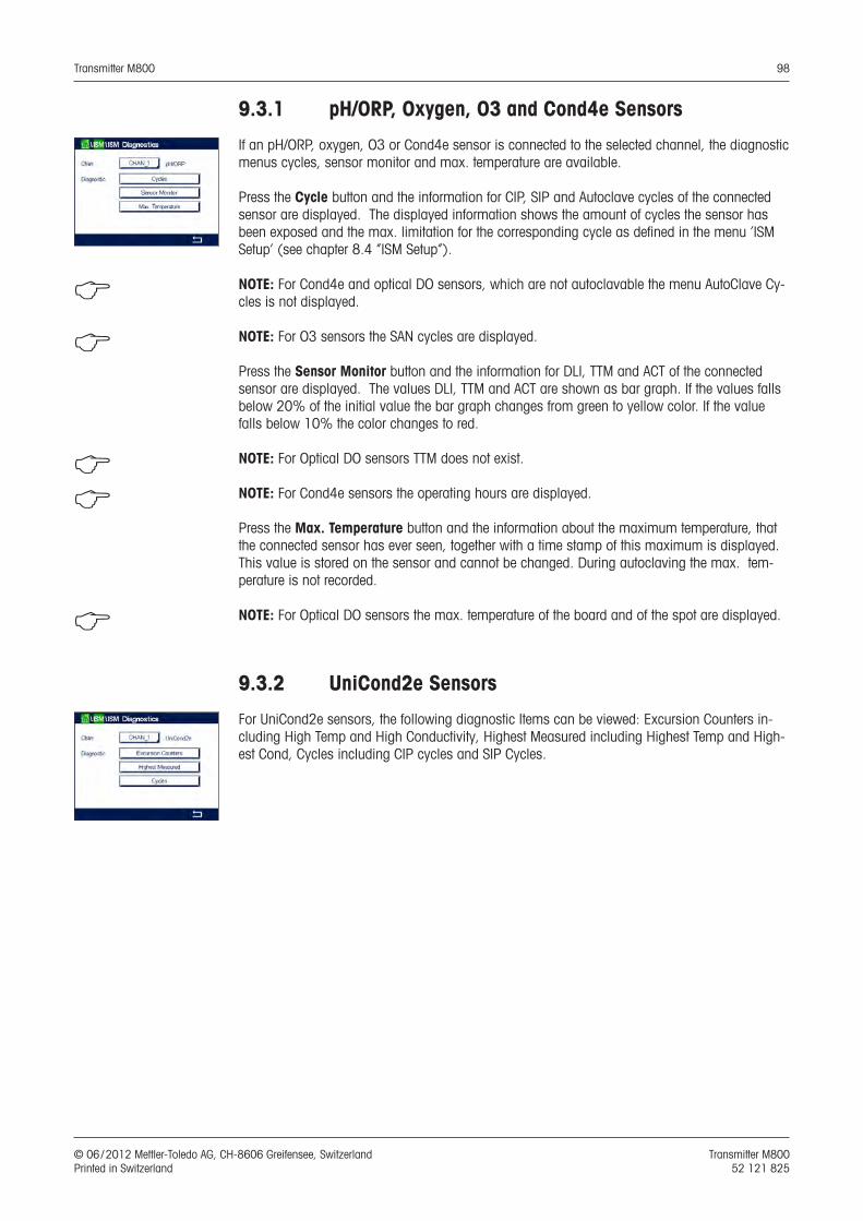
Transmitter M800 98
© 06 / 2012 Mettler-Toledo AG, CH-8606 Greifensee, Switzerland Transmitter M800 Printed in Switzerland 52 121 825
9.3.1 pH/ORP, Oxygen, O3 and Cond4e Sensors
If an pH/ORP, oxygen, O3 or Cond4e sensor is connected to the selected channel, the diagnostic menus cycles, sensor monitor and max. temperature are available.
Press the Cycle button and the information for CIP, SIP and Autoclave cycles of the connected sensor are displayed. The displayed information shows the amount of cycles the sensor has been exposed and the max. limitation for the corresponding cycle as defined in the menu ‘ISM Setup’ (see chapter 8.4 ”ISM Setup”).
h NOTE: For Cond4e and optical DO sensors, which are not autoclavable the menu AutoClave Cy-cles is not displayed.
h NOTE: For O3 sensors the SAN cycles are displayed.
Press the Sensor Monitor button and the information for DLI, TTM and ACT of the connected sensor are displayed. The values DLI, TTM and ACT are shown as bar graph. If the values falls below 20% of the initial value the bar graph changes from green to yellow color. If the value falls below 10% the color changes to red.
h NOTE: For Optical DO sensors TTM does not exist.
h NOTE: For Cond4e sensors the operating hours are displayed.
Press the Max. Temperature button and the information about the maximum temperature, that the connected sensor has ever seen, together with a time stamp of this maximum is displayed. This value is stored on the sensor and cannot be changed. During autoclaving the max. tem-perature is not recorded.
h NOTE: For Optical DO sensors the max. temperature of the board and of the spot are displayed.
9.3.2 UniCond2e Sensors
For UniCond2e sensors, the following diagnostic Items can be viewed: Excursion Counters in-cluding High Temp and High Conductivity, Highest Measured including Highest Temp and High-est Cond, Cycles including CIP cycles and SIP Cycles.
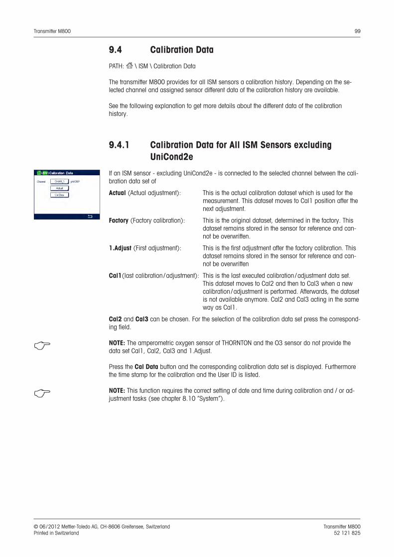
Transmitter M800 99
© 06 / 2012 Mettler-Toledo AG, CH-8606 Greifensee, Switzerland Transmitter M800 Printed in Switzerland 52 121 825
9.4 Calibration Data
PATH: H \ ISM \ Calibration Data
The transmitter M800 provides for all ISM sensors a calibration history. Depending on the se-lected channel and assigned sensor different data of the calibration history are available.
See the following explanation to get more details about the different data of the calibration history.
9.4.1 Calibration Data for All ISM Sensors excluding UniCond2e
If an ISM sensor - excluding UniCond2e - is connected to the selected channel between the cali-bration data set of
Actual (Actual adjustment): This is the actual calibration dataset which is used for the measurement. This dataset moves to Cal1 position after the next adjustment.
Factory (Factory calibration): This is the original dataset, determined in the factory. This dataset remains stored in the sensor for reference and can-not be overwritten.
1.Adjust (First adjustment): This is the first adjustment after the factory calibration. This dataset remains stored in the sensor for reference and can-not be overwritten
Cal1(last calibration / adjustment): This is the last executed calibration / adjustment data set. This dataset moves to Cal2 and then to Cal3 when a new calibration / adjustment is performed. Afterwards, the dataset is not available anymore. Cal2 and Cal3 acting in the same way as Cal1.
Cal2 and Cal3 can be chosen. For the selection of the calibration data set press the correspond-ing field.
h NOTE: The amperometric oxygen sensor of THORNTON and the O3 sensor do not provide the data set Cal1, Cal2, Cal3 and 1.Adjust.
Press the Cal Data button and the corresponding calibration data set is displayed. Furthermore the time stamp for the calibration and the User ID is listed.
h NOTE: This function requires the correct setting of date and time during calibration and / or ad-justment tasks (see chapter 8.10 “System”).
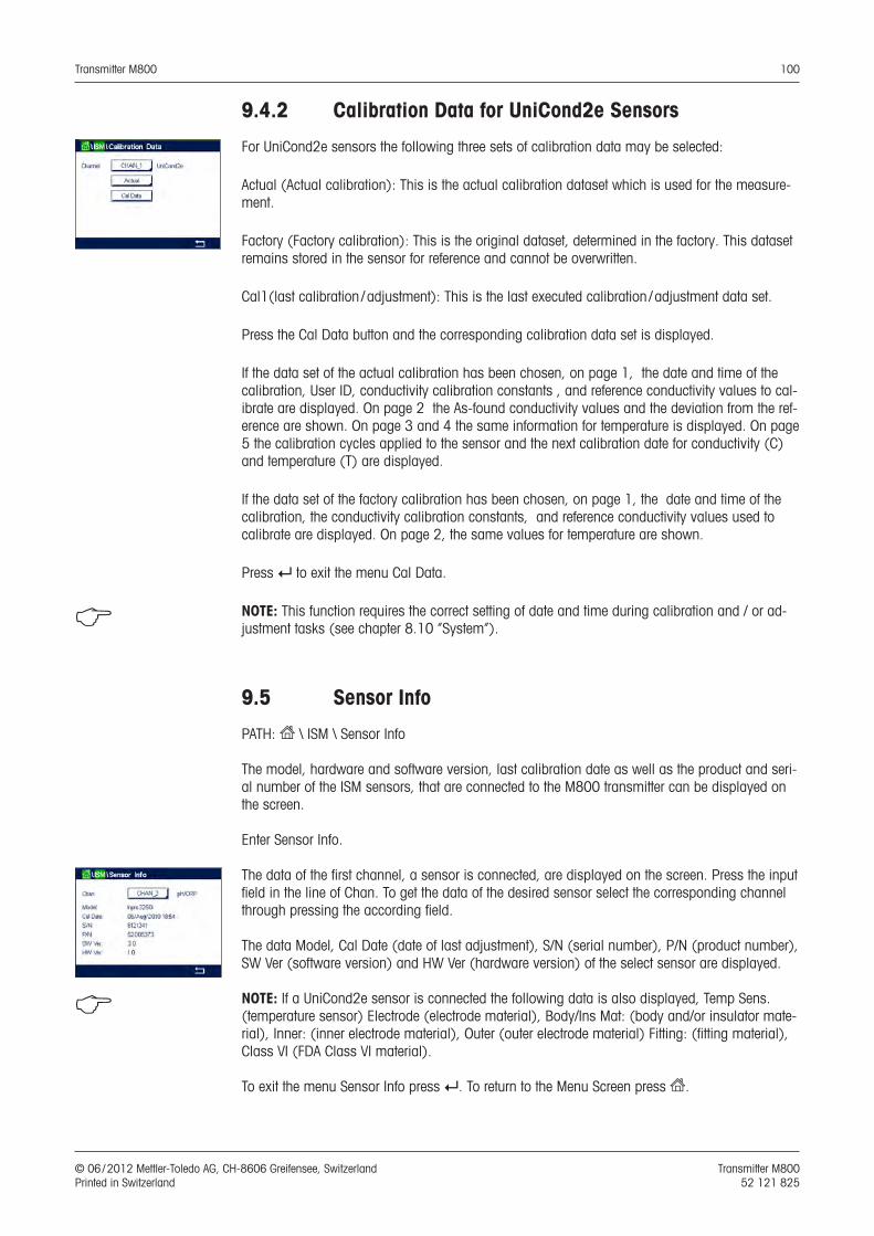
Transmitter M800 100
© 06 / 2012 Mettler-Toledo AG, CH-8606 Greifensee, Switzerland Transmitter M800 Printed in Switzerland 52 121 825
9.4.2 Calibration Data for UniCond2e Sensors
For UniCond2e sensors the following three sets of calibration data may be selected:
Actual (Actual calibration): This is the actual calibration dataset which is used for the measure-ment.
Factory (Factory calibration): This is the original dataset, determined in the factory. This dataset remains stored in the sensor for reference and cannot be overwritten.
Cal1(last calibration / adjustment): This is the last executed calibration / adjustment data set.
Press the Cal Data button and the corresponding calibration data set is displayed.
If the data set of the actual calibration has been chosen, on page 1, the date and time of the calibration, User ID, conductivity calibration constants , and reference conductivity values to cal-ibrate are displayed. On page 2 the As-found conductivity values and the deviation from the ref-erence are shown. On page 3 and 4 the same information for temperature is displayed. On page 5 the calibration cycles applied to the sensor and the next calibration date for conductivity (C) and temperature (T) are displayed.
If the data set of the factory calibration has been chosen, on page 1, the date and time of the calibration, the conductivity calibration constants, and reference conductivity values used to calibrate are displayed. On page 2, the same values for temperature are shown.
Press e to exit the menu Cal Data.
h NOTE: This function requires the correct setting of date and time during calibration and / or ad-justment tasks (see chapter 8.10 “System”).
9.5 Sensor Info
PATH: H \ ISM \ Sensor Info
The model, hardware and software version, last calibration date as well as the product and seri-al number of the ISM sensors, that are connected to the M800 transmitter can be displayed on the screen.
Enter Sensor Info.
The data of the first channel, a sensor is connected, are displayed on the screen. Press the input field in the line of Chan. To get the data of the desired sensor select the corresponding channel through pressing the according field.
The data Model, Cal Date (date of last adjustment), S/N (serial number), P/N (product number), SW Ver (software version) and HW Ver (hardware version) of the select sensor are displayed.
h NOTE: If a UniCond2e sensor is connected the following data is also displayed, Temp Sens. (temperature sensor) Electrode (electrode material), Body/Ins Mat: (body and/or insulator mate-rial), Inner: (inner electrode material), Outer (outer electrode material) Fitting: (fitting material), Class VI (FDA Class VI material).
To exit the menu Sensor Info press e. To return to the Menu Screen press H.
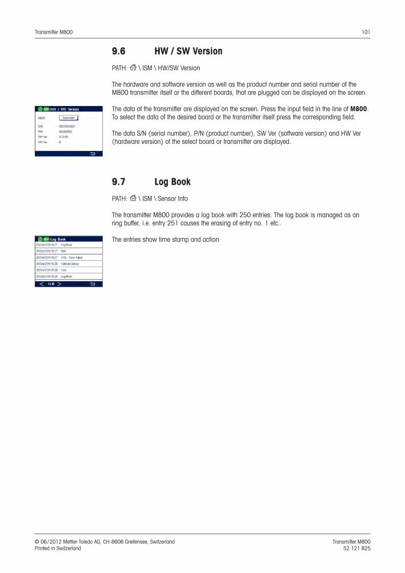
Transmitter M800 101
© 06 / 2012 Mettler-Toledo AG, CH-8606 Greifensee, Switzerland Transmitter M800 Printed in Switzerland 52 121 825
9.6 HW / SW Version
PATH: H \ ISM \ HW/SW Version
The hardware and software version as well as the product number and serial number of the M800 transmitter itself or the different boards, that are plugged can be displayed on the screen.
The data of the transmitter are displayed on the screen. Press the input field in the line of M800. To select the data of the desired board or the transmitter itself press the corresponding field.
The data S/N (serial number), P/N (product number), SW Ver (software version) and HW Ver (hardware version) of the select board or transmitter are displayed.
9.7 Log Book
PATH: H \ ISM \ Sensor Info
The transmitter M800 provides a log book with 250 entries. The log book is managed as an ring buffer, i.e. entry 251 causes the erasing of entry no. 1 etc..
The entries show time stamp and action.
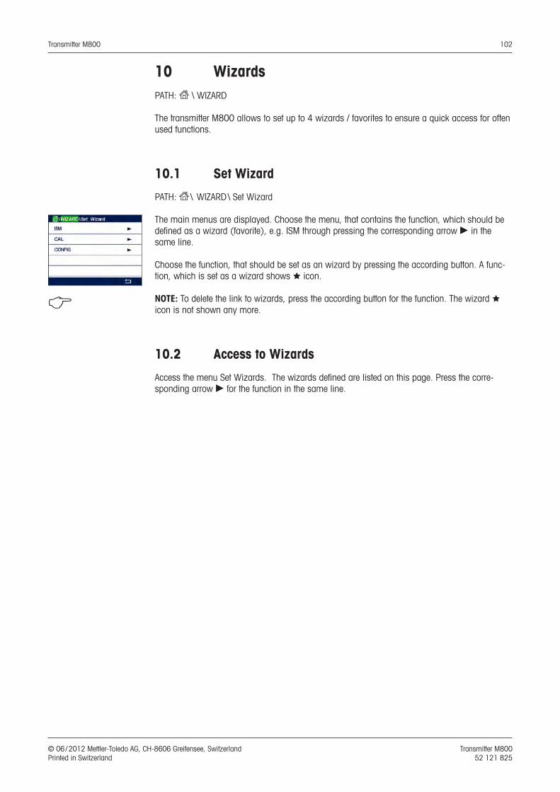
Transmitter M800 102
© 06 / 2012 Mettler-Toledo AG, CH-8606 Greifensee, Switzerland Transmitter M800 Printed in Switzerland 52 121 825
10 WizardsPATH: H \ WIZARD
The transmitter M800 allows to set up to 4 wizards / favorites to ensure a quick access for often used functions.
10.1 Set Wizard
PATH: H \ WIZARD \ Set Wizard
The main menus are displayed. Choose the menu, that contains the function, which should be defined as a wizard (favorite), e.g. ISM through pressing the corresponding arrow c in the same line.
Choose the function, that should be set as an wizard by pressing the according button. A func-tion, which is set as a wizard shows S icon.
h NOTE: To delete the link to wizards, press the according button for the function. The wizard S icon is not shown any more.
10.2 Access to Wizards
Access the menu Set Wizards. The wizards defined are listed on this page. Press the corre-sponding arrow c for the function in the same line.
Transmitter M800 103
© 06 / 2012 Mettler-Toledo AG, CH-8606 Greifensee, Switzerland Transmitter M800 Printed in Switzerland 52 121 825
11 Maintenance
11.1 Front panel cleaning
Clean the front panel with a damp soft cloth (water only, no solvents). Gently wipe the surface and dry with a soft cloth.
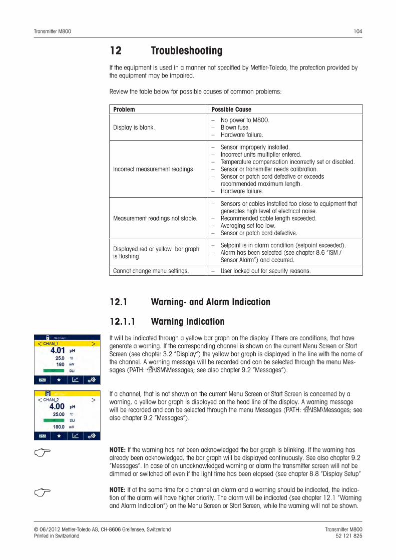
Transmitter M800 104
© 06 / 2012 Mettler-Toledo AG, CH-8606 Greifensee, Switzerland Transmitter M800 Printed in Switzerland 52 121 825
12 TroubleshootingIf the equipment is used in a manner not specified by Mettler-Toledo, the protection provided by the equipment may be impaired.
Review the table below for possible causes of common problems:
Problem Possible Cause
Display is blank.– No power to M800.– Blown fuse.– Hardware failure.
Incorrect measurement readings.
– Sensor improperly installed.– Incorrect units multiplier entered.– Temperature compensation incorrectly set or disabled.– Sensor or transmitter needs calibration.– Sensor or patch cord defective or exceeds
recommended maximum length.– Hardware failure.
Measurement readings not stable.
– Sensors or cables installed too close to equipment that generates high level of electrical noise.
– Recommended cable length exceeded.– Averaging set too low.– Sensor or patch cord defective.
Displayed red or yellow bar graph is flashing.
– Setpoint is in alarm condition (setpoint exceeded).– Alarm has been selected (see chapter 8.6 “ISM /
Sensor Alarm”) and occurred.
Cannot change menu settings. – User locked out for security reasons.
12.1 Warning- and Alarm Indication
12.1.1 Warning Indication
It will be indicated through a yellow bar graph on the display if there are conditions, that have generate a warning. If the corresponding channel is shown on the current Menu Screen or Start Screen (see chapter 3.2 “Display”) the yellow bar graph is displayed in the line with the name of the channel. A warning message will be recorded and can be selected through the menu Mes-sages (PATH: H\ISM\Messages; see also chapter 9.2 “Messages”).
If a channel, that is not shown on the current Menu Screen or Start Screen is concerned by a warning, a yellow bar graph is displayed on the head line of the display. A warning message will be recorded and can be selected through the menu Messages (PATH: H\ISM\Messages; see also chapter 9.2 “Messages”).
h NOTE: If the warning has not been acknowledged the bar graph is blinking. If the warning has already been acknowledged, the bar graph will be displayed continuously. See also chapter 9.2 “Messages”. In case of an unacknowledged warning or alarm the transmitter screen will not be dimmed or switched off even if the light time has been elapsed (see chapter 8.8 “Display Setup”
h NOTE: If at the same time for a channel an alarm and a warning should be indicated, the indica-tion of the alarm will have higher priority. The alarm will be indicated (see chapter 12.1 “Warning and Alarm Indication”) on the Menu Screen or Start Screen, while the warning will not be shown.
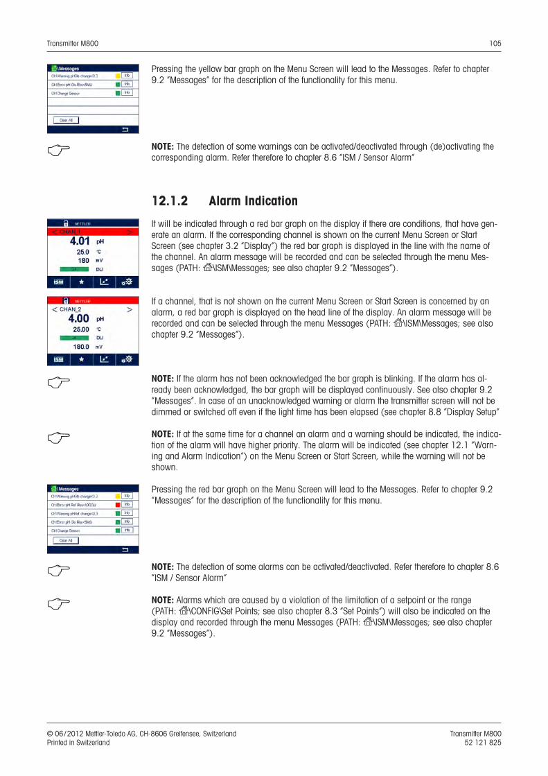
Transmitter M800 105
© 06 / 2012 Mettler-Toledo AG, CH-8606 Greifensee, Switzerland Transmitter M800 Printed in Switzerland 52 121 825
Pressing the yellow bar graph on the Menu Screen will lead to the Messages. Refer to chapter 9.2 “Messages” for the description of the functionality for this menu.
h NOTE: The detection of some warnings can be activated/deactivated through (de)activating the corresponding alarm. Refer therefore to chapter 8.6 “ISM / Sensor Alarm”
12.1.2 Alarm Indication
It will be indicated through a red bar graph on the display if there are conditions, that have gen-erate an alarm. If the corresponding channel is shown on the current Menu Screen or Start Screen (see chapter 3.2 “Display”) the red bar graph is displayed in the line with the name of the channel. An alarm message will be recorded and can be selected through the menu Mes-sages (PATH: H\ISM\Messages; see also chapter 9.2 “Messages”).
If a channel, that is not shown on the current Menu Screen or Start Screen is concerned by an alarm, a red bar graph is displayed on the head line of the display. An alarm message will be recorded and can be selected through the menu Messages (PATH: H\ISM\Messages; see also chapter 9.2 “Messages”).
h NOTE: If the alarm has not been acknowledged the bar graph is blinking. If the alarm has al-ready been acknowledged, the bar graph will be displayed continuously. See also chapter 9.2 “Messages”. In case of an unacknowledged warning or alarm the transmitter screen will not be dimmed or switched off even if the light time has been elapsed (see chapter 8.8 “Display Setup”
h NOTE: If at the same time for a channel an alarm and a warning should be indicated, the indica-tion of the alarm will have higher priority. The alarm will be indicated (see chapter 12.1 “Warn-ing and Alarm Indication”) on the Menu Screen or Start Screen, while the warning will not be shown.
Pressing the red bar graph on the Menu Screen will lead to the Messages. Refer to chapter 9.2 “Messages” for the description of the functionality for this menu.
h NOTE: The detection of some alarms can be activated/deactivated. Refer therefore to chapter 8.6 “ISM / Sensor Alarm”
h NOTE: Alarms which are caused by a violation of the limitation of a setpoint or the range (PATH: H\CONFIG\Set Points; see also chapter 8.3 “Set Points”) will also be indicated on the display and recorded through the menu Messages (PATH: H\ISM\Messages; see also chapter 9.2 “Messages”).
Transmitter M800 106
© 06 / 2012 Mettler-Toledo AG, CH-8606 Greifensee, Switzerland Transmitter M800 Printed in Switzerland 52 121 825
13 Accessories and Spare PartsPlease contact your local Mettler-Toledo sales office or representative for details for additional accessories and spare parts.
Description Order no.Pipe Mount Kit for 1/2DIN models 52 500 212
Panel Mount Kit for 1/2DIN models 52 500 213
Protective Hood for 1/2DIN models 52 500 214
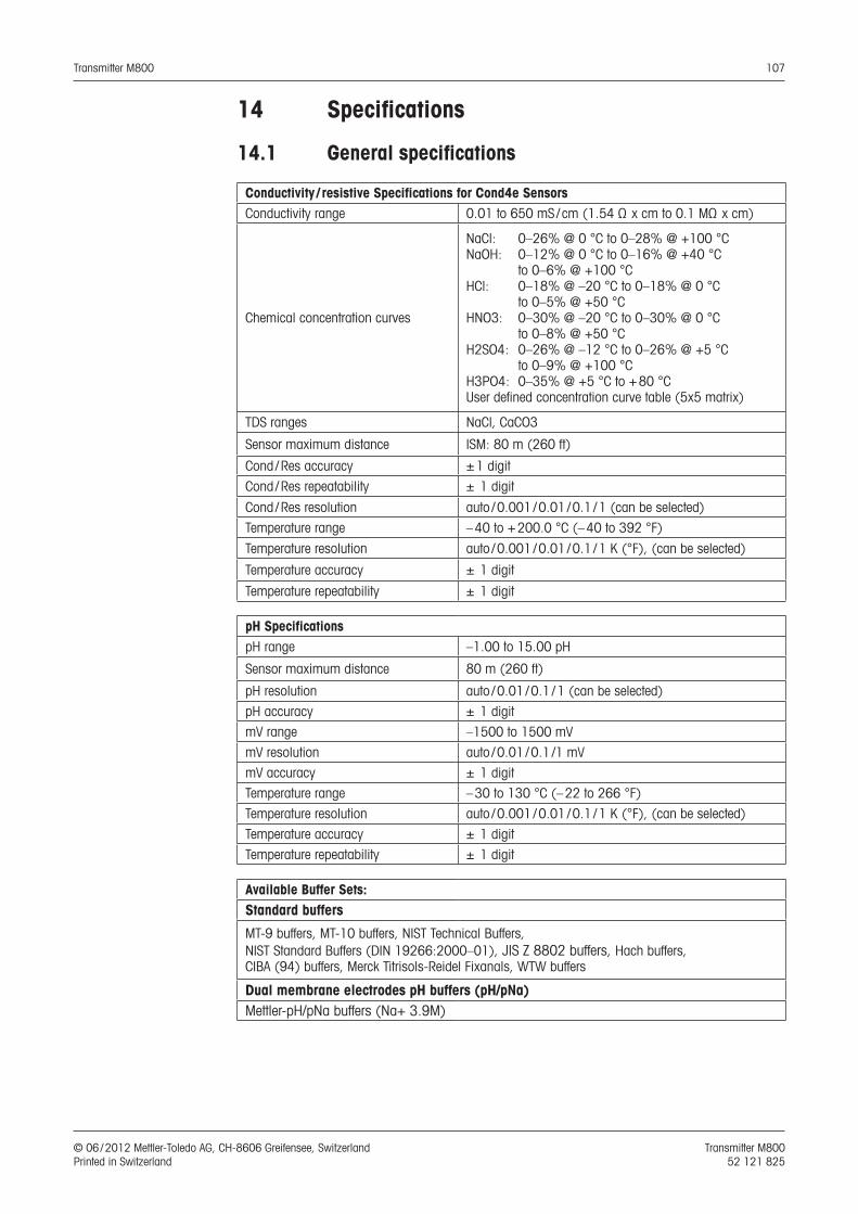
Transmitter M800 107
© 06 / 2012 Mettler-Toledo AG, CH-8606 Greifensee, Switzerland Transmitter M800 Printed in Switzerland 52 121 825
14 Specifications
14.1 General specifications
Conductivity / resistive Specifications for Cond4e SensorsConductivity range 0.01 to 650 mS / cm (1.54 Ω x cm to 0.1 MΩ x cm)
Chemical concentration curves
NaCl: 0–26% @ 0 °C to 0–28% @ +100 °CNaOH: 0–12% @ 0 °C to 0–16% @ +40 °C
to 0–6% @ +100 °CHCl: 0–18% @ –20 °C to 0–18% @ 0 °C
to 0–5% @ +50 °CHNO3: 0–30% @ –20 °C to 0–30% @ 0 °C
to 0–8% @ +50 °CH2SO4: 0–26% @ –12 °C to 0–26% @ +5 °C
to 0–9% @ +100 °CH3PO4: 0–35% @ +5 °C to + 80 °CUser defined concentration curve table (5x5 matrix)
TDS ranges NaCl, CaCO3
Sensor maximum distance ISM: 80 m (260 ft)
Cond / Res accuracy ± 1 digit
Cond / Res repeatability ± 1 digit
Cond / Res resolution auto / 0.001 / 0.01 / 0.1 / 1 (can be selected)
Temperature range – 40 to + 200.0 °C (– 40 to 392 °F)
Temperature resolution auto / 0.001 / 0.01 / 0.1 / 1 K (°F), (can be selected)
Temperature accuracy ± 1 digit
Temperature repeatability ± 1 digit
pH SpecificationspH range –1.00 to 15.00 pH
Sensor maximum distance 80 m (260 ft)
pH resolution auto / 0.01 / 0.1 / 1 (can be selected)
pH accuracy ± 1 digit
mV range –1500 to 1500 mV
mV resolution auto / 0.01 / 0.1 /1 mV
mV accuracy ± 1 digit
Temperature range – 30 to 130 °C (– 22 to 266 °F)
Temperature resolution auto / 0.001 / 0.01 / 0.1 / 1 K (°F), (can be selected)
Temperature accuracy ± 1 digit
Temperature repeatability ± 1 digit
Available Buffer Sets:Standard buffers
MT-9 buffers, MT-10 buffers, NIST Technical Buffers, NIST Standard Buffers (DIN 19266:2000–01), JIS Z 8802 buffers, Hach buffers, CIBA (94) buffers, Merck Titrisols-Reidel Fixanals, WTW buffers
Dual membrane electrodes pH buffers (pH/pNa)Mettler-pH/pNa buffers (Na+ 3.9M)
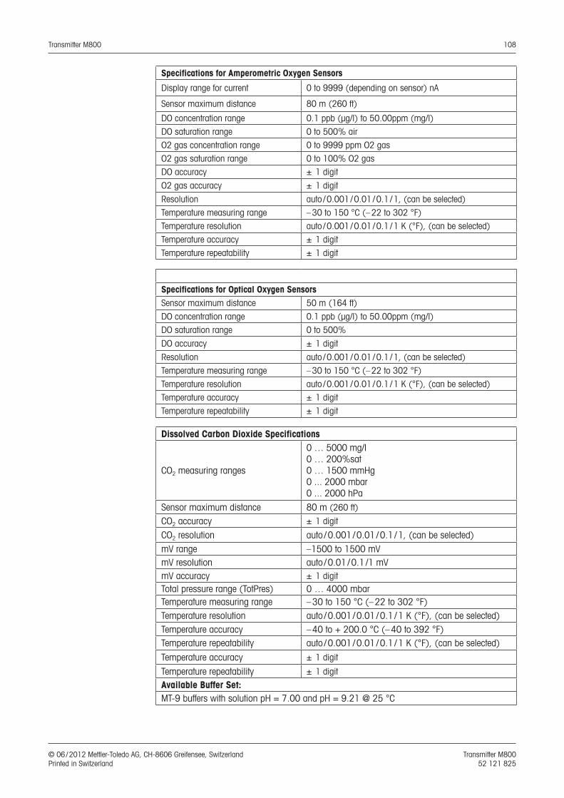
Transmitter M800 108
© 06 / 2012 Mettler-Toledo AG, CH-8606 Greifensee, Switzerland Transmitter M800 Printed in Switzerland 52 121 825
Specifications for Amperometric Oxygen Sensors
Display range for current 0 to 9999 (depending on sensor) nA
Sensor maximum distance 80 m (260 ft)
DO concentration range 0.1 ppb (µg/l) to 50.00ppm (mg/l)
DO saturation range 0 to 500% air
O2 gas concentration range 0 to 9999 ppm O2 gas
O2 gas saturation range 0 to 100% O2 gasDO accuracy ± 1 digit
O2 gas accuracy ± 1 digit
Resolution auto / 0.001 / 0.01 / 0.1 / 1, (can be selected)
Temperature measuring range – 30 to 150 °C (– 22 to 302 °F)
Temperature resolution auto / 0.001 / 0.01 / 0.1 / 1 K (°F), (can be selected)
Temperature accuracy ± 1 digit
Temperature repeatability ± 1 digit
Specifications for Optical Oxygen SensorsSensor maximum distance 50 m (164 ft)
DO concentration range 0.1 ppb (µg/l) to 50.00ppm (mg/l) DO saturation range 0 to 500%
DO accuracy ± 1 digit
Resolution auto / 0.001 / 0.01 / 0.1 / 1, (can be selected)
Temperature measuring range – 30 to 150 °C (– 22 to 302 °F)
Temperature resolution auto / 0.001 / 0.01 / 0.1 / 1 K (°F), (can be selected)
Temperature accuracy ± 1 digit
Temperature repeatability ± 1 digit
Dissolved Carbon Dioxide Specifications
CO2 measuring ranges
0 … 5000 mg/l0 … 200%sat0 … 1500 mmHg0 ... 2000 mbar0 ... 2000 hPa
Sensor maximum distance 80 m (260 ft)
CO2 accuracy ± 1 digit
CO2 resolution auto / 0.001 / 0.01 / 0.1 / 1, (can be selected)mV range –1500 to 1500 mVmV resolution auto / 0.01 / 0.1 /1 mVmV accuracy ± 1 digitTotal pressure range (TotPres) 0 … 4000 mbarTemperature measuring range – 30 to 150 °C (– 22 to 302 °F)Temperature resolution auto / 0.001 / 0.01 / 0.1 / 1 K (°F), (can be selected) Temperature accuracy – 40 to + 200.0 °C (– 40 to 392 °F)Temperature repeatability auto / 0.001 / 0.01 / 0.1 / 1 K (°F), (can be selected)
Temperature accuracy ± 1 digit
Temperature repeatability ± 1 digit
Available Buffer Set:MT-9 buffers with solution pH = 7.00 and pH = 9.21 @ 25 °C
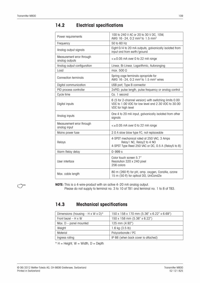
Transmitter M800 109
© 06 / 2012 Mettler-Toledo AG, CH-8606 Greifensee, Switzerland Transmitter M800 Printed in Switzerland 52 121 825
14.2 Electrical specifications
Power requirements 100 to 240 V AC or 20 to 30 V DC, 10W, AWG 16 – 24, 0.2 mm2 to 1.5 mm2
Frequency 50 to 60 Hz
Analog output signals Eight 0 / 4 to 20 mA outputs, galvanically isolated from input and from earth / ground
Measurement error through analog outputs < ± 0.05 mA over 0 to 22 mA range
Analog output configuration Linear, Bi-Linear, Logarithmic, Autoranging
Load max. 500 Ω
Connection terminals Spring cage terminals apropriate for AWG 16 – 24, 0.2 mm2 to 1.5 mm2 wires
Digital communication USB port, Type B connector
PID process controller 2xPID; pulse length, pulse frequency or analog control
Cycle time Ca. 1 second
Digital inputs6 (5 for 2-channel version) with swtiching limits 0.00 VDC to 1.00 VDC for low level and 2.30 VDC to 30.00 VDC for high level
Analog inputs One 4 to 20 mA input, galvanically isolated from other signals
Measurement error through analog input < ± 0.05 mA over 0 to 22 mA range
Mains power fuse 2.0 A slow blow type FC, not replaceable
Relays4-SPST mechanical rated at 250 VAC, 3 Amps Relay1 NC, Relay2 to 4 NO4-SPST Type Reed 250 VAC or DC, 0.5 A (Relay5 to 8)
Alarm Relay delay 0–999 s
User interfaceColor touch screen 5.7’’ Resolution 320 x 240 pixel256 colors
Max. cable length 80 m (260 ft) for pH, amp. oxygen, Cond4e, ozone15 m (50 ft) for optical DO, UniCond2e
h NOTE: This is a 4-wire-product with an active 4–20 mA analog output. Please do not supply to terminal no. 3 to 10 of TB1 and terminal no. 1 to 8 of TB3.
14.3 Mechanical specifications
Dimensions (housing – H x W x D)* 150 x 158 x 170 mm (5.36” x 6.22” x 6.69”)
Front bezel – H x W 150 x 158 mm (5.36” x 6.22”)
Max. D – panel mounted 125 mm (4.92”)
Weight 1.6 kg (3.5 lb)
Material Polycarbonate / PC
Ingress rating IP 66 (when back cover is attached)
* H = Height, W = Width, D = Depth
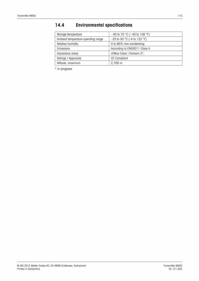
Transmitter M800 110
© 06 / 2012 Mettler-Toledo AG, CH-8606 Greifensee, Switzerland Transmitter M800 Printed in Switzerland 52 121 825
14.4 Environmental specifications
Storage temperature – 40 to 70 °C (– 40 to 158 °F)
Ambient temperature operating range –20 to 50 °C (-4 to 122 °F)
Relative humidity 0 to 95% non-condensing
Emissions According to EN55011 Class A
Hazardous areas cFMus Class I Division 2*,
Ratings / Approvals CE Compliant
Altitude, maximum 2,700 m
* in progress
Transmitter M800 111
© 06 / 2012 Mettler-Toledo AG, CH-8606 Greifensee, Switzerland Transmitter M800 Printed in Switzerland 52 121 825
15 WarrantyMETTLER TOLEDO warrants this product to be free from significant deviations in material and workmanship for a period of one year from the date of purchase. If repair is necessary and not the result of abuse or misuse within the warranty period, please return by freight pre-paid and amendment will be made without any charge. METTLER TOLEDO’s Customer Service Dept. will determine if the product problem is due to deviations or customer abuse. Out-of-warranty prod-ucts will be repaired on an exchange basis at cost.
The above warranty is the only warranty made by METTLER TOLEDO and is lieu of all other war-ranties, expressed or implied, including, without limitation, implied warranties of merchantability and fitness for a particular purpose. METTLER TOLEDO shall not be liable for any loss, claim, expense or damage caused by, contributed to or arising out of the acts or omissions of the Buyer or Third Parties, whether negligent or otherwise. In no event shall METTLER TOLEDO’s liability for any cause of action whatsoever exceed the cost of the item giving rise to the claim, whether based in contract, warranty, indemnity, or tort (including negligence).
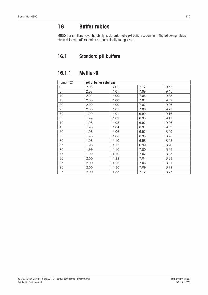
Transmitter M800 112
© 06 / 2012 Mettler-Toledo AG, CH-8606 Greifensee, Switzerland Transmitter M800 Printed in Switzerland 52 121 825
16 Buffer tablesM800 transmitters have the ability to do automatic pH buffer recognition. The following tables show different buffers that are automatically recognized.
16.1 Standard pH buffers
16.1.1 Mettler-9
Temp (°C) pH of buffer solutions0 2.03 4.01 7.12 9.525 2.02 4.01 7.09 9.4510 2.01 4.00 7.06 9.3815 2.00 4.00 7.04 9.3220 2.00 4.00 7.02 9.2625 2.00 4.01 7.00 9.2130 1.99 4.01 6.99 9.1635 1.99 4.02 6.98 9.1140 1.98 4.03 6.97 9.0645 1.98 4.04 6.97 9.0350 1.98 4.06 6.97 8.9955 1.98 4.08 6.98 8.9660 1.98 4.10 6.98 8.9365 1.98 4.13 6.99 8.9070 1.99 4.16 7.00 8.8875 1.99 4.19 7.02 8.8580 2.00 4.22 7.04 8.8385 2.00 4.26 7.06 8.8190 2.00 4.30 7.09 8.7995 2.00 4.35 7.12 8.77
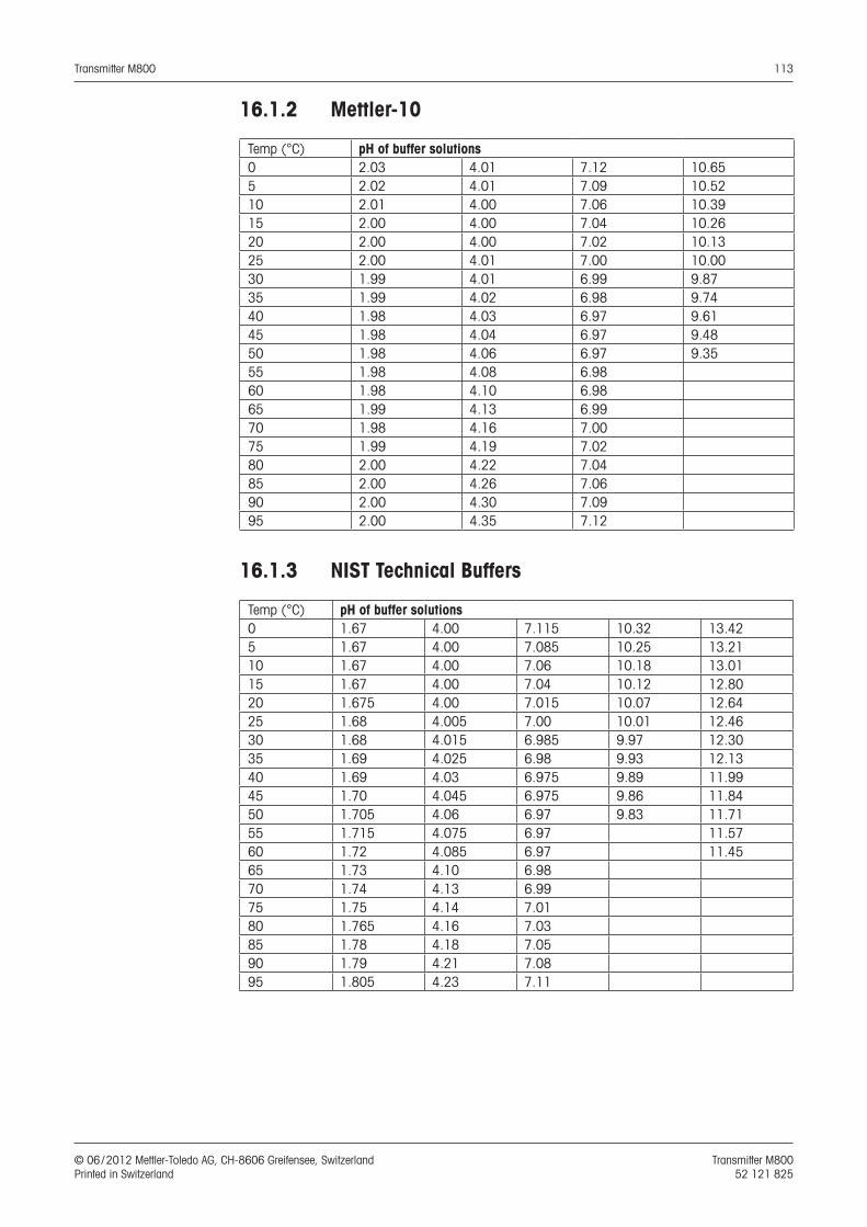
Transmitter M800 113
© 06 / 2012 Mettler-Toledo AG, CH-8606 Greifensee, Switzerland Transmitter M800 Printed in Switzerland 52 121 825
16.1.2 Mettler-10
Temp (°C) pH of buffer solutions0 2.03 4.01 7.12 10.655 2.02 4.01 7.09 10.5210 2.01 4.00 7.06 10.3915 2.00 4.00 7.04 10.2620 2.00 4.00 7.02 10.1325 2.00 4.01 7.00 10.0030 1.99 4.01 6.99 9.8735 1.99 4.02 6.98 9.7440 1.98 4.03 6.97 9.6145 1.98 4.04 6.97 9.4850 1.98 4.06 6.97 9.3555 1.98 4.08 6.9860 1.98 4.10 6.9865 1.99 4.13 6.9970 1.98 4.16 7.0075 1.99 4.19 7.0280 2.00 4.22 7.0485 2.00 4.26 7.0690 2.00 4.30 7.0995 2.00 4.35 7.12
16.1.3 NIST Technical Buffers
Temp (°C) pH of buffer solutions0 1.67 4.00 7.115 10.32 13.425 1.67 4.00 7.085 10.25 13.2110 1.67 4.00 7.06 10.18 13.0115 1.67 4.00 7.04 10.12 12.8020 1.675 4.00 7.015 10.07 12.6425 1.68 4.005 7.00 10.01 12.4630 1.68 4.015 6.985 9.97 12.3035 1.69 4.025 6.98 9.93 12.1340 1.69 4.03 6.975 9.89 11.9945 1.70 4.045 6.975 9.86 11.8450 1.705 4.06 6.97 9.83 11.7155 1.715 4.075 6.97 11.5760 1.72 4.085 6.97 11.4565 1.73 4.10 6.9870 1.74 4.13 6.9975 1.75 4.14 7.0180 1.765 4.16 7.0385 1.78 4.18 7.0590 1.79 4.21 7.0895 1.805 4.23 7.11
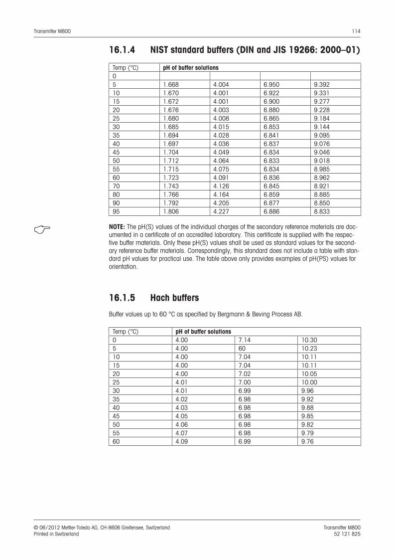
Transmitter M800 114
© 06 / 2012 Mettler-Toledo AG, CH-8606 Greifensee, Switzerland Transmitter M800 Printed in Switzerland 52 121 825
16.1.4 NIST standard buffers (DIN and JIS 19266: 2000–01)
Temp (°C) pH of buffer solutions05 1.668 4.004 6.950 9.39210 1.670 4.001 6.922 9.33115 1.672 4.001 6.900 9.27720 1.676 4.003 6.880 9.22825 1.680 4.008 6.865 9.18430 1.685 4.015 6.853 9.14435 1.694 4.028 6.841 9.09540 1.697 4.036 6.837 9.07645 1.704 4.049 6.834 9.04650 1.712 4.064 6.833 9.01855 1.715 4.075 6.834 8.98560 1.723 4.091 6.836 8.96270 1.743 4.126 6.845 8.92180 1.766 4.164 6.859 8.88590 1.792 4.205 6.877 8.85095 1.806 4.227 6.886 8.833
h NOTE: The pH(S) values of the individual charges of the secondary reference materials are doc-umented in a certificate of an accredited laboratory. This certificate is supplied with the respec-tive buffer materials. Only these pH(S) values shall be used as standard values for the second-ary reference buffer materials. Correspondingly, this standard does not include a table with stan-dard pH values for practical use. The table above only provides examples of pH(PS) values for orientation.
16.1.5 Hach buffers
Buffer values up to 60 °C as specified by Bergmann & Beving Process AB.
Temp (°C) pH of buffer solutions0 4.00 7.14 10.305 4.00 60 10.2310 4.00 7.04 10.1115 4.00 7.04 10.1120 4.00 7.02 10.0525 4.01 7.00 10.0030 4.01 6.99 9.9635 4.02 6.98 9.9240 4.03 6.98 9.8845 4.05 6.98 9.8550 4.06 6.98 9.8255 4.07 6.98 9.7960 4.09 6.99 9.76
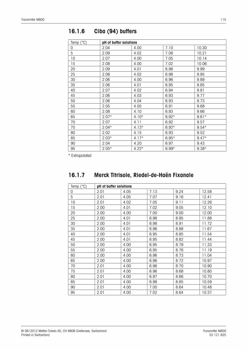
Transmitter M800 115
© 06 / 2012 Mettler-Toledo AG, CH-8606 Greifensee, Switzerland Transmitter M800 Printed in Switzerland 52 121 825
16.1.6 Ciba (94) buffers
Temp (°C) pH of buffer solutions0 2.04 4.00 7.10 10.305 2.09 4.02 7.08 10.2110 2.07 4.00 7.05 10.1415 2.08 4.00 7.02 10.0620 2.09 4.01 6.98 9.9925 2.08 4.02 6.98 9.9530 2.06 4.00 6.96 9.8935 2.06 4.01 6.95 9.8540 2.07 4.02 6.94 9.8145 2.06 4.03 6.93 9.7750 2.06 4.04 6.93 9.7355 2.05 4.05 6.91 9.6860 2.08 4.10 6.93 9.6665 2.07* 4.10* 6.92* 9.61*70 2.07 4.11 6.92 9.5775 2.04* 4.13* 6.92* 9.54*80 2.02 4.15 6.93 9.5285 2.03* 4.17* 6.95* 9.47*90 2.04 4.20 6.97 9.4395 2.05* 4.22* 6.99* 9.38*
* Extrapolated
16.1.7 Merck Titrisole, Riedel-de-Haën Fixanale
Temp (°C) pH of buffer solutions0 2.01 4.05 7.13 9.24 12.585 2.01 4.05 7.07 9.16 12.4110 2.01 4.02 7.05 9.11 12.2615 2.00 4.01 7.02 9.05 12.1020 2.00 4.00 7.00 9.00 12.0025 2.00 4.01 6.98 8.95 11.8830 2.00 4.01 6.98 8.91 11.7235 2.00 4.01 6.96 8.88 11.6740 2.00 4.01 6.95 8.85 11.5445 2.00 4.01 6.95 8.82 11.4450 2.00 4.00 6.95 8.79 11.3355 2.00 4.00 6.95 8.76 11.1960 2.00 4.00 6.96 8.73 11.0465 2.00 4.00 6.96 8.72 10.9770 2.01 4.00 6.96 8.70 10.9075 2.01 4.00 6.96 8.68 10.8080 2.01 4.00 6.97 8.66 10.7085 2.01 4.00 6.98 8.65 10.5990 2.01 4.00 7.00 8.64 10.4895 2.01 4.00 7.02 8.64 10.37
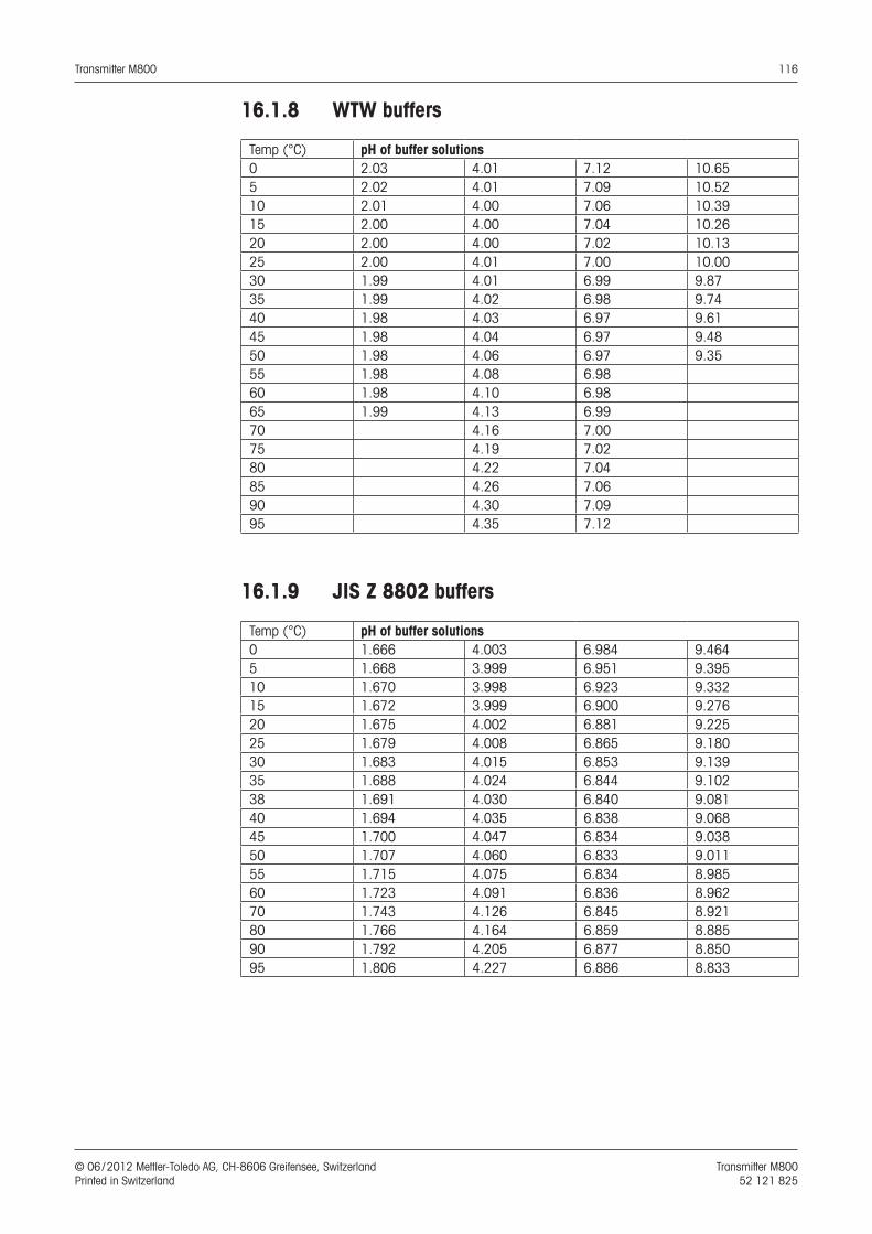
Transmitter M800 116
© 06 / 2012 Mettler-Toledo AG, CH-8606 Greifensee, Switzerland Transmitter M800 Printed in Switzerland 52 121 825
16.1.8 WTW buffers
Temp (°C) pH of buffer solutions0 2.03 4.01 7.12 10.655 2.02 4.01 7.09 10.5210 2.01 4.00 7.06 10.3915 2.00 4.00 7.04 10.2620 2.00 4.00 7.02 10.1325 2.00 4.01 7.00 10.0030 1.99 4.01 6.99 9.8735 1.99 4.02 6.98 9.7440 1.98 4.03 6.97 9.6145 1.98 4.04 6.97 9.4850 1.98 4.06 6.97 9.3555 1.98 4.08 6.9860 1.98 4.10 6.9865 1.99 4.13 6.9970 4.16 7.0075 4.19 7.0280 4.22 7.0485 4.26 7.0690 4.30 7.0995 4.35 7.12
16.1.9 JIS Z 8802 buffers
Temp (°C) pH of buffer solutions0 1.666 4.003 6.984 9.4645 1.668 3.999 6.951 9.39510 1.670 3.998 6.923 9.33215 1.672 3.999 6.900 9.27620 1.675 4.002 6.881 9.22525 1.679 4.008 6.865 9.18030 1.683 4.015 6.853 9.13935 1.688 4.024 6.844 9.10238 1.691 4.030 6.840 9.08140 1.694 4.035 6.838 9.06845 1.700 4.047 6.834 9.03850 1.707 4.060 6.833 9.01155 1.715 4.075 6.834 8.98560 1.723 4.091 6.836 8.96270 1.743 4.126 6.845 8.92180 1.766 4.164 6.859 8.88590 1.792 4.205 6.877 8.85095 1.806 4.227 6.886 8.833
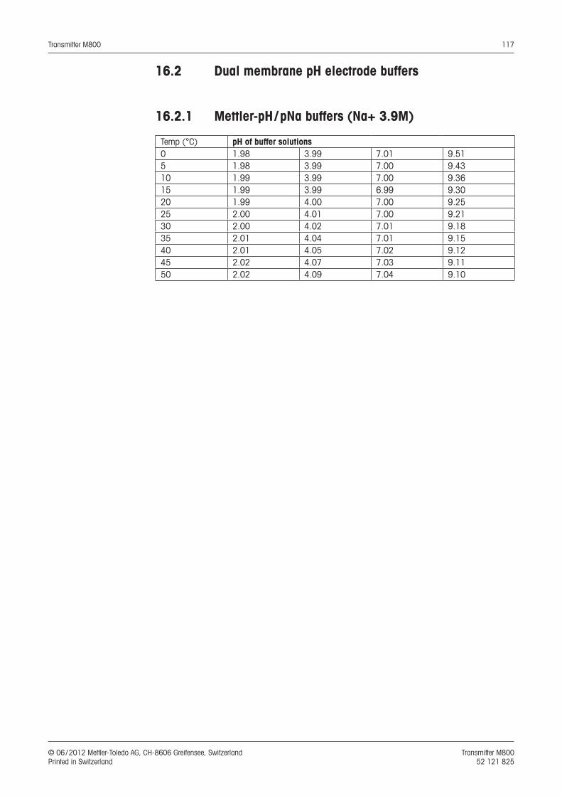
Transmitter M800 117
© 06 / 2012 Mettler-Toledo AG, CH-8606 Greifensee, Switzerland Transmitter M800 Printed in Switzerland 52 121 825
16.2 Dual membrane pH electrode buffers
16.2.1 Mettler-pH / pNa buffers (Na+ 3.9M)
Temp (°C) pH of buffer solutions0 1.98 3.99 7.01 9.515 1.98 3.99 7.00 9.4310 1.99 3.99 7.00 9.3615 1.99 3.99 6.99 9.3020 1.99 4.00 7.00 9.2525 2.00 4.01 7.00 9.2130 2.00 4.02 7.01 9.1835 2.01 4.04 7.01 9.1540 2.01 4.05 7.02 9.1245 2.02 4.07 7.03 9.1150 2.02 4.09 7.04 9.10
www.mt.com/pro
METTLER TOLEDO Market Organizations
Management Systemcertified according toISO 9001 / ISO 14001
9001certified
ISO 14001certified
ISO
Sales and Service:
AustraliaMettler-Toledo Ltd.220 Turner StreetPort MelbourneAUS-3207 Melbourne /VICPhone +61 1300 659 761Fax +61 3 9645 3935e-mail [email protected]
AustriaMettler-Toledo Ges.m.b.H.Südrandstraße 17A-1230 WienPhone +43 1 604 19 80Fax +43 1 604 28 80e-mail [email protected]
BrazilMettler-Toledo Ind. e Com. Ltda.Alameda Araguaia, 451AlphavilleBR-06455-000 Barueri /SPPhone +55 11 4166 7444Fax +55 11 4166 7401e-mail [email protected]
ChinaMettler-Toledo Instruments(Shanghai) Co. Ltd.589 Gui Ping RoadCao He JingCN-200233 ShanghaiPhone +86 21 64 85 04 35Fax +86 21 64 85 33 51e-mail [email protected]
CroatiaMettler-Toledo d.o.o.Mandlova 3HR-10000 ZagrebPhone +385 1 292 06 33Fax +385 1 295 81 40e-mail [email protected]
Czech RepublicMettler-Toledo s.r.o.Trebohosticka 2283/2CZ-100 00 Praha 10 Phone +420 2 72 123 150Fax +420 2 72 123 170e-mail [email protected]
DenmarkMettler-Toledo A /SNaverland 8DK-2600 GlostrupPhone +45 43 27 08 00Fax +45 43 27 08 28e-mail [email protected]
FranceMettler-ToledoAnalyse Industrielle S.A.S.30, Boulevard de DouaumontF-75017 ParisPhone +33 1 47 37 06 00Fax +33 1 47 37 46 26e-mail [email protected]
GermanyMettler-Toledo GmbHProzeßanalytikOckerweg 3D-35396 GießenPhone +49 641 507 333Fax +49 641 507 397e-mail [email protected]
Great BritainMettler-Toledo LTD64 Boston Road, Beaumont LeysGB-Leicester LE4 1AW Phone +44 116 235 7070Fax +44 116 236 5500e-mail [email protected]
HungaryMettler-Toledo Kereskedelmi KFTTeve u. 41HU-1139 BudapestPhone +36 1 288 40 40Fax +36 1 288 40 50e-mail [email protected]
IndiaMettler-Toledo India Private LimitedAmar Hill, Saki Vihar RoadPowaiIN-400 072 MumbaiPhone +91 22 2857 0808Fax +91 22 2857 5071e-mail [email protected]
ItalyMettler-Toledo S.p.A.Via Vialba 42I -20026 Novate MilanesePhone +39 02 333 321Fax +39 02 356 [email protected]
JapanMettler-Toledo K.K.Process Division6F Ikenohata Nisshoku Bldg.2-9-7, IkenohataTaito-kuJP-110-0008 TokyoPhone +81 3 5815 5606Fax +81 3 5815 5626e-mail [email protected]
MalaysiaMettler-Toledo (M) Sdn BhdBangunan Electroscon Holding, U 1-01Lot 8 Jalan Astaka U8/84Seksyen U8, Bukit JelutongMY-40150 Shah Alam SelangorPhone +60 3 78 44 58 88 Fax +60 3 78 45 87 [email protected]
MexicoMettler-Toledo S.A. de C.V.Ejercito Nacional #340Col. Chapultepec MoralesDel. Miguel HidalgoMX-11570 México D.F.Phone +52 55 1946 0900e-mail [email protected]
PolandMettler-Toledo (Poland) Sp.z.o.o.ul. Poleczki 21PL-02-822 WarszawaPhone +48 22 545 06 80Fax +48 22 545 06 88e-mail [email protected]
RussiaMettler-Toledo Vostok ZAOSretenskij Bulvar 6/1Office 6RU-101000 MoscowPhone +7 495 621 56 66Fax +7 495 621 63 53e-mail [email protected]
SingaporeMettler-Toledo (S) Pte. Ltd.Block 28Ayer Rajah Crescent #05-01SG-139959 SingaporePhone +65 6890 00 11Fax +65 6890 00 12
+65 6890 00 13e-mail [email protected]
SlovakiaMettler-Toledo s.r.o.Hattalova 12/ASK-83103 BratislavaPhone +421 2 4444 12 20-2Fax +421 2 4444 12 23e-mail [email protected]
SloveniaMettler-Toledo d.o.o.Pot heroja Trtnika 26SI -1261 Ljubljana-DobrunjePhone +386 1 530 80 50Fax +386 1 562 17 89e-mail [email protected]
South KoreaMettler-Toledo (Korea) Ltd.Yeil Building 1 & 2 F124-5, YangJe-DongSeCho-KuKR-137-130 SeoulPhone +82 2 3498 3500Fax +82 2 3498 3555e-mail [email protected]
SpainMettler-Toledo S.A.E.C /Miguel Hernández, 69-71ES-08908 L’Hospitalet de Llobregat(Barcelona)Phone +34 902 32 00 23Fax +34 902 32 00 24e-mail [email protected]
SwedenMettler-Toledo ABVirkesvägen 10Box 92161SE-12008 StockholmPhone +46 8 702 50 00Fax +46 8 642 45 62e-mail [email protected]
SwitzerlandMettler-Toledo (Schweiz) GmbHIm LangacherPostfachCH-8606 GreifenseePhone +41 44 944 45 45Fax +41 44 944 45 10e-mail [email protected]
ThailandMettler-Toledo (Thailand) Ltd.272 Soi Soonvijai 4Rama 9 Rd., BangkapiHuay KwangTH-10320 BangkokPhone +66 2 723 03 00Fax +66 2 719 64 [email protected]
USA/CanadaMettler-Toledo Ingold, Inc.36 Middlesex TurnpikeBedford, MA 01730, USAPhone +1 781 301 8800Freephone +1 800 352 8763Fax +1 781 271 0681e-mail [email protected]
Subject to technical changes.© Mettler-Toledo AG, Process Analytics06/12 Printed in Switzerland. 52 121 825
Mettler-Toledo AG, Process AnalyticsIm Hackacker 15, CH-8902 Urdorf, SwitzerlandTel. +41 44 729 62 11, Fax +41 44 729 66 36
N315