OPERATION MANUAL - Appion · PDF file4 Warnings and Safety Information IMPORTANT - READ THIS...
23
FOR REFRIGERANT RECOVERY OPERATION MANUAL COPYRIGHT © 2016 - APPION INC. - ALL RIGHTS RESERVED APPION TM AND G5TWIN TM ARE TRADEMARKS OF APPION INC. ⚠ WARNING TO REDUCE THE RISK OF INJURY OR PRODUCT DAMAGE, READ OPERATION MANUAL PRIOR TO OPERATING PRODUCT. Explosion Hazard. Do NOT use with hydrocarbons. See page 4. ⚠ DANGER www.AppionTools.com
Transcript of OPERATION MANUAL - Appion · PDF file4 Warnings and Safety Information IMPORTANT - READ THIS...

FOR REFRIGERANT RECOVERY
OPERATION MANUAL
COPYRIGHT © 2016 - APPION INC. - ALL RIGHTS RESERVEDAPPIONTM AND G5TWINTM ARE TRADEMARKS OF APPION INC.
⚠ WARNINGTO REDUCE THE RISK OF INJURY OR PRODUCT DAMAGE, READ OPERATION MANUAL PRIOR TO OPERATING PRODUCT.
Explosion Hazard. Do NOT use with hydrocarbons. See page 4.⚠ DANGER
www.AppionTools.com

3
Table of ContentsWarnings and Safety Information .................................................................4 - 5Refrigerant Storage Container Safety ...............................................................6Getting Started ..............................................................................................7
Machine Usage G5Twin Operational Layout ..........................................................................8 Preparing for Operation ................................................................................8 Standard Recovery Procedure .......................................................................9 High-Speed Direct Liquid Recovery Procedure .............................................. 10 Standard Recovery with Inline Cooling ........................................................ 11 Push Pull Recovery Procedure ..................................................................... 12 Purging Non-Condensables from Recovery Cylinders .................................... 13 Changing Between Refrigerant Types .......................................................... 13 Storing the Machine Between Uses .............................................................. 13
Helpful Hints Planning Ahead .......................................................................................... 14 Tips for Maximizing Recovery Performance ............................................. 14-17 Extension Cords and Low Voltage ................................................................ 17
Care and Maintenance Screen Cleaning & Replacement .................................................................. 18 Planned Maintenance & Bench Test ............................................................. 18
Specifications and Support Troubleshooting Guide ............................................................................... 19 G5Twin Specifications, Repair Part Kits & Accessories ................................... 20 Parts Diagram and Operational Diagrams ................................................ 21-22 Manufacturers Limited Warranty ................................................................. 23
Welcome to the G5TwinThank you for your purchase of the Appion G5Twin Refrigerant Recovery Machine. This machine was designed to deliver fast, reliable recovery of Class III, IV and V refrigerants. Use of this machine for any other purpose is done at your own risk.
Faster refrigerant recovery requires proper training, preparation, and operation. Working with refrigerants under pressure also presents numerous safety risks and hazards.
To safely reach the full potential of this machine, read this manual and all safety material before use.
G5TWIN OPERATION MANUAL© 2016 APPION INC. - ALL RIGHTS RESERVED

4
Warnings and Safety InformationIMPORTANT - READ THIS MANUAL BEFORE OPERATIONThis Operation Manual contains important information for protecting your safety and preventing equipment problems. Unsafe operation could lead to serious injury or death to you or others. For best results and safe operation, read this entire manual before operation. Keep this manual in a safe, accessible location during operation.
⚠ WARNING When working with refrigerants, always use the appropriate Personal Protective Equipment (PPE), including eye and hand protection. Read all Material Safety Data Sheets (MSDS) for any compounds that you are likely to encounter during operation. Failure to do so could lead to injury or death.
OPERATOR TRAINING, CERTIFICATION AND RESPONSIBILITY⚠ NOTICE This machine compresses and pumps liquid and vapor refrigerants at high pressures, which
can create dangerous conditions. This equipment is for use by technicians that are professionally trained and certified in the safe handling of refrigerant, and safe refrigerant recovery techniques.
PERSONAL PROTECTIVE EQUIPMENT AND MSDS
HAZARD: RISK OF EXPLOSION OR FIRE⚠ DANGER Use of this equipment may pose certain explosion and fire hazards.
WHAT CAN HAPPEN HOW TO PREVENT ITIt is possible for electrical components within the unit to spark. If electrical sparks come into contact with flammable vapors, they may ignite, causing fire or explosion.
Use only in well ventilated areas. In enclosed areas, mechanical ventilation should provide at least four air changes per hour.
Flammable/combustible gases and air may become unknowingly ingested through leaks in hoses, gaskets, connections or leaking seals, leading to compression of these gases. Air and hydrocarbons, if pumped to a tank, create an explosive mixture that random static electricity could ignite.
Do not use in the vicinity of spilled or open containers of gasoline, propane, butane, acetylene, or other flammable gases.
Do not use near open sewer lines which may be emitting sewer gases.
Flammable substances may ignite or explode when compressed in certain situations.
Do not use this machine to pump hydrocarbons, including blends containing butane, isobutane, or propane. Hydrocarbons are flammable substances and may ignite or explode when compressed in certain situations.
Improper use of extensions cords may result in overheating or fire in the cord or machine.
Use only 12AWG or 10AWG extension cords: - Up to 25 Feet: 12/3 UL/CSA cord - Up to 100 Feet: 10/3 UL/CSA cord
⚠ NOTICE Keep away from children at all times. Do not leave unattended.
⚠ NOTICE Never defeat the safety features of this product. Do not operate with missing, broken, or unauthorized parts. Remove broken or altered equipment from service immediately.
G5TWIN OPERATION MANUAL© 2016 APPION INC. - ALL RIGHTS RESERVED

5
Warnings and Safety Information (continued)
HAZARD: RISK TO BREATHING (ASPHYXIATION)⚠ DANGER Air and refrigerants pumped by this machine may pose certain breathing hazards.
WHAT CAN HAPPEN HOW TO PREVENT ITRefrigerant vapors may be harmful or toxic when inhaled.
Use only in well ventilated areas. In enclosed areas, mechanical ventilation should provide at least four air changes per hour.
Compressed air from this machine may contain carbon monoxide or toxic refrigerant vapors.
Air from this machine should never be used to supply air for human consumption
HAZARD: RISK FROM MOVING COMPONENTS⚠ WARNING This machine is equipped with a fan and motor rotating at high speeds.
WHAT CAN HAPPEN HOW TO PREVENT ITDebris or other objects may enter the machine housing through the air vents, causing machine damage.
Be sure the area around the machine is free and clear of debris before operating the machine.
Physical damage may occur to body parts, tools, or other objects if inserted into the air vents of the machine while it is running.
Always unplug the machine and ensure that the fan and motor are not rotating before opening the case or inserting any object into the machine.
Damage may occur to the machine and surrounding objects if the machine is dropped while running.
Use caution while moving this equipment, especially during operation.
HAZARD: RISK FROM NOISE⚠ CAUTION Moving components, high airflow, and pumping refrigerant can all cause noise.
WHAT CAN HAPPEN HOW TO PREVENT ITUnder some conditions and duration of use, noise from the unit may contribute to hearing loss.
Always wear certified safety equipment, including ANSI or equivalent hearing protection.
HAZARD: RISK FROM UNATTENDED OPERATION⚠ CAUTION Factors affecting operation may change during the recovery process.
WHAT CAN HAPPEN HOW TO PREVENT ITAs refrigerant recovery is a dynamic process, and often performed in open spaces, factors affecting the operation of the unit may change.
Always remain in attendance with the machine while it is operating.
Remain observant to changes in environment, refrigerant pressure and refrigerant temperature.
G5TWIN OPERATION MANUAL© 2016 APPION INC. - ALL RIGHTS RESERVED

6 G5TWIN OPERATION MANUAL
⚠ WARNING Use only DOT CFR 49 or UL-approved storage containers for recovered refrigerant.
WHAT CAN HAPPEN HOW TO PREVENT ITRefrigerant storage containers may vent or explode when the working pressure of the container is exceeded.
Refrigerant storage containers are designed with different working pressures. Verify that the rating of the storage cylinder is appropriate for the refrigerant being recovered.
For R-410a, 4BA400 and 4BW400 are appropriate rat-ings for refrigerant storage containers.
“80% Shut Off Switches,” also known as Tank Overfill Sensors and Overfill Protection devices, may fail to prevent overfilling of the storage cylinder, leading to venting or explosion.
These sensors only cut power to the recovery machine, and do not stop the flow of refrigerant, which may continue due to a siphon, or due to temperature-induced migration.
Do not rely on these switches to prevent overfilling. Only a refrigerant scale can provide an active and accurate measurement of the amount of refrigerant in the storage container.
Do not rely on these switches to stop the flow of refrigerant into the container. Only the valves on the recovery machine and on the cylinder can stop the flow of refrigerant into the container.
Refrigerant expands when heated (Diagram 1), and storage containers may vent or explode when filled over 80% capacity.
A refrigerant scale must be used to monitor the amount of refrigerant in the storage container.
Be sure to close the valves on the storage container when it has reached 80% capacity.
Filled to80% Capacity
Filled to90% Capacity
Diagram 1Overfilled storage containers may explode due to liquid refrigerant expanding when heated.
Transportation of refrigerant storage cylinders more than 80% full is a DOT violation.
Refrigerant Storage Container Safety
© 2016 APPION INC. - ALL RIGHTS RESERVED

7
Getting Started⚠ CAUTION Always use a grounded outlet that meets minimum voltage supply requirements for industrial
equipment. Do not use with portable power generators.⚠ CAUTION Always open valves slowly for safety, and to check for leaks.
⚠ CAUTION The G5Twin is equipped with a 550psi (38.6 kg/cm2) pressure shut off switch to protect the machine from damage. This does not prevent overfilling of the storage container. (See Page 6)
G5TWIN OPERATION MANUAL© 2016 APPION INC. - ALL RIGHTS RESERVED
CHECKING YOUR RECOVERY EQUIPMENT
ACCESSORY EQUIPMENT
Before connecting or operating the G5Twin, verify that the G5Twin will be able to operate properly:
• Check that the debris screen at the inlet fitting is clean before starting every job. This screen prevents damage to the machine that may get past the inline filter. When pumping dirty/used refrigerant, this screen may quickly clog and slow the process when used without an inline filter.
• Verify the power source provides adequate voltage at the machine while it is running (within 10% of the rated power). When using an extension cord, follow the sizing guidelines on Page 4.
Review the information for Care and Maintenance on Page 17 regularly to ensure optimal performance.
Additional equipment may be used to connect the G5Twin to the system you are recovering refrigerant from. Verify operational details and safety information from the manufacturers of other equipment before use.
• . A leaking hose may cause venting of refrigerant, and may introduce atmospheric air or other contaminants into the recovered refrigerant. Examine the gaskets on each hose to ensure they are intact, checking for any damage or wear that may lead to leaks.
• Use the shortest length of 3/8”-diameter hoses possible on every connection. IMPORTANT: Do not use “quick disconnect” or “auto-shutoff” hoses for refrigerant recovery, as this can bring the recovery to a halt.
• Use Valve Core Removal Tools with a ball valve (such as Appion MegaFlow VCT) to remove all “Schrader”-type access valve cores from the System access fittings. This prevents restrictions that would otherwise limit the performance of the G5Twin and/or cause overheating of the recovery cylinder. See Page 15 for more information.
• The recovery cylinder should have extra capacity beyond the amount you intend to recover. For maximum recovery speeds, use a recovery cylinder that is already evacuated (500 microns or better). Note: new recovery cylinders may not be sufficiently evacuated - always verify before use.
• Check your refrigerant scale with a known weight to ensure that is operating correctly. A malfunctioning scale may not alert you to the amount of refrigerant in the storage container.
• Examine your external manifold gauges for proper valve operation and calibration of the gauges. Contact the manifold gauge manufacturer for instructions in this process.
• Use a new inline filter dryer as shown when pumping dirty refrigerant. Replace the filter dryer after each use. If the filter has exceeded its capacity, this may affect the performance of the machine.
• Use a sight glass to verify liquid flow. This can also be useful for troubleshooting purposes. Make sure that the sight glass is in good condition and does not leak.
⚠ CAUTION

Machine Usage
8G5TWIN OPERATION MANUAL© 2016 APPION INC. - ALL RIGHTS RESERVED
PREPARING FOR OPERATIONEvery recovery procedure starts with the same five basics:
• Remove any access valve cores from the AC/R System access fittings with a Valve Core Removal Tool;
• Remove any core depressors from the hose fittings. Do not use “quick disconnect” or “auto-shutoff” hose connections for refrigerant recovery, as this can bring the recovery to a halt. Use only ball valves for low-loss.
• Use the shortest length of 3/8”-diameter hoses possible on every connection. Even with 1/4” fittings, the larger hose diameter can deliver better performance during recovery.
• Purge the hoses of non-condensables as you connect the hoses, as needed, using best practices to minimize any refrigerant release (aka “de minimis”). Excess non-condensables can cause tank overheating, and may contaminate recovered refrigerant.
• Connect the G5Twin to a grounded power source for the proper voltage of the machine (115v/230v). If using an extension cord, follow the cord sizing guidelines on Page 4.
✪ For additional refrigerant recovery tips, see pages 14-17.
G5TWIN OPERATIONAL LAYOUT
Horizontal Knobs: Valves Closed Vertical Knobs: Valves Open
Diagram 2
Diagram 3

Machine Usage
STANDARD RECOVERY PROCEDURE
⚠ CAUTION To reduce the risk of injury or product damage, read this entire operating manual, with particular emphasis on the Safety and Preparation sections (Page 4-8), prior to operating the G5Twin.
1. Setup the G5Twin as shown in Diagram 4 (below). Make sure that all connections are tight. A. Connect the AC/R System Liquid Port to the Manifold high side. B. Connect the AC/R System Vapor Port to the Manifold low side. C. Connect the Manifold Center port to the G5Twin input port. D. Connect the G5Twin output port to the Vapor Port on the Recovery Cylinder.
Diagram 4Recover into the Vapor Port of the Recovery Cylinder for faster recovery.
OPTIONAL: To improve tank cooling, start with the recovery cylinder upside down, and flip the tank right-side up near the end of the vapor recovery.
2. Close both valves on the Manifold Gauge Set.
3. Open both valves on the G5Twin, open the Valve Core Removal Tool ball valves at the system (if equipped), and open the Recovery Cylinder Vapor Port.
Make sure to completely open the Recovery Cylinder valve to prevent “output restrictions” (See Tip #1).
4. Turn on the G5Twin. The compressor and fan should start.
5. Slowly open the Manifold High Side (liquid) valve. Removing liquid first will keep recovery time to a minimum, and improve cooling properties of the recovery cylinder. NOTE: Overheating or slow recovery speeds may be caused by “input restrictions” (See Tip #2).
6. When all the liquid has been removed, completely open the Manifold Low Side (vapor) valve. Both sides should now be fully open to maximize vapor flow.
7. Continue to run the G5Twin until the EPA-required vacuum is achieved.
8. Close both valves on the Manifold Gauge set.
9. Turn off the G5Twin, then close the output valve on the G5Twin.
10. Close the G5Twin input valve, close the valves on the Recovery Cylinder, and disconnect the hoses.
DC
B
A
9 G5TWIN OPERATION MANUAL© 2016 APPION INC. - ALL RIGHTS RESERVED

Machine Usage⚠ CAUTION To reduce the risk of injury or product damage, read this entire operating manual, with
particular emphasis on the Safety and Preparation sections (Page 4-8), prior to operating the G5Twin.
HIGH-SPEED DIRECT LIQUID PROCEDUREThis recovery method allows for the fastest possible “direct liquid” recovery speeds. To maximize recovery rates, be sure to follow all of the Preparing for Operation information on Page 8.
Diagram 5This recovery method allows for the fastest possible “direct liquid” recovery speeds, although the “vapor” phase of recovery may take a little longer.
2. Close the Valve Core Removal Tool (VCRT) ball valves at both of the AC/R System Liquid and Vapor ports.
3. Open both valves on the G5Twin, and open both valves on the Recovery Cylinder.Make sure to completely open the Recovery Cylinder valves to prevent “output restrictions” (See Tip #1).
4. Turn on the G5Twin. The compressor and fan should start.
5. Begin liquid recovery by opening both of the VCRT ball valves at the AC/R System access ports.
6. When all the liquid has been removed: close the Recovery Cylinder Vapor Valve.
7. Continue to run the G5Twin until the EPA-required vacuum is achieved.
8. Close both of the VCRT ball valves.
9. Turn off the G5Twin, then close the valves on the G5Twin.
10. Close the valves on the Recovery Cylinder and disconnect the hoses.
✪ For additional refrigerant recovery tips, see pages 14-17.
A BC
1. Setup the G5Twin as shown in Diagram 5 (below). Make sure that all connections are tight. A. Connect the AC/R System Liquid Port to the G5Twin input port. B. Connect the G5Twin output port to the Liquid Port on the Recovery Cylinder. C. Connect the Cylinder Vapor Port to the AC/R System Vapor Port. D. Connect a Compound Pressure Gauge to the AC/R System Vapor Port using a T-fitting or a side-port on a valve core removal tool.
10G5TWIN OPERATION MANUAL© 2016 APPION INC. - ALL RIGHTS RESERVED
D

Machine Usage⚠ CAUTION To reduce the risk of injury or product damage, read this entire operating manual, with
particular emphasis on the Safety and Preparation sections (Page 4-8), prior to operating the G5Twin.
STANDARD RECOVERY WITH INLINE COOLINGThis ALTERNATIVE procedure allows the user to switch between the Standard Recovery Procedure and the High-Speed Direct Liquid Procedure during recovery, leading to reduced temperatures and back-pressure from the recovery cylinder. This can be particularly useful with R410A and/or high ambient conditions.
Diagram 6This method allows the user to switch between Standard Recovery and High-Speed Direct Liquid, which can cool the recovery cylinder as needed.
2. Close both valves on the Manifold Gauge Set. Open both valves on the G5Twin, open both valves on the Recovery Cylinder, and open the VCRT ball valves at the AC/R System access ports (if equipped).
Make sure to completely open the Recovery Cylinder valves to prevent “output restrictions” (See Tip #1).
3. Turn on the G5Twin. The compressor and fan should start.
4. Begin liquid recovery by opening the Manifold High Side (liquid).
5. When all the liquid has been removed: close the Recovery Cylinder Vapor Valve, open the Manifold Low Side (vapor) valve, and the hose ball valve at the system vapor port (if equipped).
6. Continue to run the G5Twin until the EPA-required vacuum is achieved.
7. Close both valves on the Manifold Gauge set.
8. Turn off the G5Twin, then close the valves on the G5Twin.
9. Close the valves on the Recovery Cylinder and VCRT ball valves (if equipped), and disconnect the hoses.
A
B
C D
E E
1. Setup the G5Twin as shown in Diagram 6 (below). Make sure that all connections are tight. A. Connect the AC/R System Liquid Port to the Manifold high side. B. Connect the AC/R System Vapor Port to the Manifold low side. C. Connect the Manifold Center port to the G5Twin input port. D. Connect the G5Twin output port to the Liquid Port on the Recovery Cylinder. E. Connect the Cylinder Vapor Port to the AC/R System Vapor Port, using a T-fitting or a side-port on a valve core removal tool.
11 G5TWIN OPERATION MANUAL© 2016 APPION INC. - ALL RIGHTS RESERVED

Machine Usage⚠ CAUTION To reduce the risk of injury or product damage, read this entire operating manual, with
particular emphasis on the Safety and Preparation sections (Page 4-8), prior to operating the G5Twin.
PUSH/PULL RECOVERY PROCEDUREThe Push/Pull method induces a siphon from the system directly into the recovery cylinder using the G5Twin. This method is useful for recovering large amounts of liquid from a system. This will only work on large systems where the liquid can be accessed easily. Do not attempt this on systems that contain less than 15 lbs. of liquid refrigerant (unless there is a receiver tank), or it may not work correctly.
⚠ CAUTION Once the siphon starts, it can continue to fill the tank even when the machine has been powered off. To avoid overfilling, you must close all valves on the tank and system when finished.
Diagram 7The Push/Pull recovery method induces a siphon to move large amounts of liquid directly from the system to the recovery cylinder.
1. Setup the G5Twin as shown in Diagram 7 (below). Make sure that all connections are tight. A. Connect the AC/R System Vapor Port to the G5Twin output port. B. Connect the AC/R System Liquid Port to the Recovery Cylinder Liquid port. C. Connect the G5Twin input port to the Recovery Cylinder Vapor port.
2. Slowly open both valves on the G5Twin.
3. Turn on the G5Twin. The compressor and fan should start.
4. Slowly open the valves on the tank and system. The liquid should now begin to be pulled out of the system. You can monitor the progress with an inline sight glass.
Make sure to completely open the Recovery Cylinder valves to prevent “output restrictions” (See Tip #1).
5. When all the liquid has been siphoned off, turn off the G5Twin and close all the valves.
6. You can now proceed to remove the remaining refrigerant vapor using the Standard Recovery Procedure (Page 9).
C
B
A
12G5TWIN OPERATION MANUAL© 2016 APPION INC. - ALL RIGHTS RESERVED

13 G5TWIN OPERATION MANUAL© 2016 APPION INC. - ALL RIGHTS RESERVED
Additional Machine UsagePURGING NON-CONDENSABLES FROM RECOVERY CYLINDERSIn the event that the Recovery Cylinder pressure is higher than expected, or if the recovery process seems slower than usual, use an external gauge (not the gauge on the G5Twin) and a Refrigerant Pressure/Temperature chart to check for the presence of non-condensable gases in the cylinder.
You can bleed/purge non-condensables into another cylinder following this procedure:
1. The Recovery Cylinder must remain undisturbed for at least 24 hours for the non-condensables to rise to the top of the cylinder.
2. Through a Manifold Gauge Set, connect the Recovery Cylinder Vapor Port to the Vapor Port of a second recovery cylinder.
3. Consult a Refrigerant Pressure/Temperature chart, and check the temperature of the Recovery Cylinder to determine what the pressure should be.
4. While the pressure is higher than the pressure on the chart, slowly open the Vapor Port to bleed off excess pressure until it is about 5 psi (0.35 Kg/cm2) above the pressure listed on the chart.
5. Close the valves and let the cylinder stand still for 10 minutes. Repeat if necessary.
CHANGING BETWEEN REFRIGERANT TYPESAppion refrigerant recovery machines are unique in that there is no refrigerant directly introduced into the compressor crankcase. This allows the G5Twin to easily and efficiently clear out refrigerant at the end of the recovery process. However, as with all recovery machines, trace refrigerant vapors may remain and should be cleared out when switching between different types of refrigerant.
When you are changing between refrigerant types, any refrigerant remaining in the recovery machine should be drawn into a deeply evacuated recovery cylinder before switching. Then, to prevent any cross-contamination, it is recommended that a vacuum pump be connected to the output port of the G5Twin (keep the Input Valve closed and the Output Valve open), and run the vacuum pump to completely evacuate the machine of any trace refrigerant vapors.
STORING THE MACHINE BETWEEN USESWhen storing the machine between recovery jobs, trace refrigerant vapors can continue to wear on the internal components of the machine. If the machine is fully sealed (closed valves or port covers), storing the machine in a hot truck can cause the trace vapors to expand and wear on the components further.
To minimize wear during storage, leave both valves on the G5Twin open. You can use port caps/covers to protect the machine from dirt, but make sure they do not have an airtight seal.

14G5TWIN OPERATION MANUAL© 2016 APPION INC. - ALL RIGHTS RESERVED
Helpful HintsPLAN AHEAD
It is a common belief that recovering liquid refrigerant will always be “noisy.” However, the “hammering” or “knocking” sound associated with recovering liquid can often be caused by output restrictions, which is any flow restriction between the recovery machine and the interior of the recovery cylinder. If the G5Twin is excessively noisy during liquid recovery, check for, and remove, any output restrictions.
Another common symptom of output restrictions is the recovery machine intermittently shutting off on high pressure, but resets on its own after the output pressure quickly drops in a short time. If the G5Twin shuts off on high pressure but the output pressure quickly drops, check for, and remove, any output restrictions.
Prolonged pumping against output restrictions not only slows the recovery process, but the increased load can accelerate the wear of your recovery equipment. This wear can be seen with damaged output gauges, electrical component failure, and slower performance on the bench test (see Page 18).
Remove Output Restrictions to Maximize Recovery Performance:To improve recovery performance, and prolong the life of your equipment, take the time to remove these typical output restrictions before you start:
• Remove core depressors from all of the hose fittings (they block up to 50% of the flow) - See Tip #4
• DO NOT USE refrigerant charging hoses with “quick disconnect” or “auto-shutoff” fittings
• Make sure that the recovery cylinder valve is completely opened
• Discard of used/worn hoses with deteriorating inner linings
Output Restrictions: Loud Recovery & High Pressure ShutoffTIP #1
In just a few years, refrigerant recovery has come a long way. At first glance, it’s simply the process of taking refrigerant out of a system and putting it into a storage tank. However, this simple process can rapidly become difficult and time consuming if a few things are overlooked. What follows are some notes and guidelines that we have learned over the years that can help you save time and make the job easier.
The first thing you need to do is determine the quantity and type of refrigerant that is being used in the system you are working on. Use a tank that is DOT approved for the high pressures that are present with R410a. If the system is a burnout, you will need to use a special tank marked as containing burnout and other unidentified gases and you must use extra filtration before recovery. This extra filtration is to protect your equipment from corrosion caused by acids that may be present.
If the gas in the system is fairly clean or new, then you should use a clean, new tank. If the refrigerant is going to be reclaimed, or you are going to put the refrigerant back into the system when you are done servicing it, then you should use a tank with the same type of refrigerant in it. One note of caution: If you use many different gases and you only own a single tank, you’re asking for trouble with the Environmental Protection Agency (EPA). You should own at least one tank for every type of refrigerant that you will service, and a spare tank for unknown gases and burned out systems.
15 G5TWIN OPERATION MANUAL© 2016 APPION INC. - ALL RIGHTS RESERVED
Helpful Hints (continued)
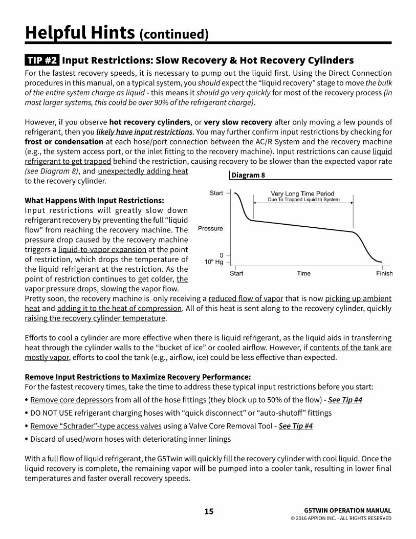
For the fastest recovery speeds, it is necessary to pump out the liquid first. Using the Direct Connection procedures in this manual, on a typical system, you should expect the “liquid recovery” stage to move the bulk of the entire system charge as liquid - this means it should go very quickly for most of the recovery process (in most larger systems, this could be over 90% of the refrigerant charge).
However, if you observe hot recovery cylinders, or very slow recovery after only moving a few pounds of refrigerant, then you likely have input restrictions. You may further confirm input restrictions by checking for frost or condensation at each hose/port connection between the AC/R System and the recovery machine (e.g., the system access port, or the inlet fitting to the recovery machine). Input restrictions can cause liquid refrigerant to get trapped behind the restriction, causing recovery to be slower than the expected vapor rate (see Diagram 8), and unexpectedly adding heat to the recovery cylinder.
What Happens With Input Restrictions:Input restrictions will greatly slow down refrigerant recovery by preventing the full “liquid flow” from reaching the recovery machine. The pressure drop caused by the recovery machine triggers a liquid-to-vapor expansion at the point of restriction, which drops the temperature of the liquid refrigerant at the restriction. As the point of restriction continues to get colder, the vapor pressure drops, slowing the vapor flow.Pretty soon, the recovery machine is only receiving a reduced flow of vapor that is now picking up ambient heat and adding it to the heat of compression. All of this heat is sent along to the recovery cylinder, quickly raising the recovery cylinder temperature.
Efforts to cool a cylinder are more effective when there is liquid refrigerant, as the liquid aids in transferring heat through the cylinder walls to the “bucket of ice” or cooled airflow. However, if contents of the tank are mostly vapor, efforts to cool the tank (e.g., airflow, ice) could be less effective than expected.
Remove Input Restrictions to Maximize Recovery Performance:For the fastest recovery times, take the time to address these typical input restrictions before you start:
• Remove core depressors from all of the hose fittings (they block up to 50% of the flow) - See Tip #4
• DO NOT USE refrigerant charging hoses with “quick disconnect” or “auto-shutoff” fittings
• Remove “Schrader”-type access valves using a Valve Core Removal Tool - See Tip #4
• Discard of used/worn hoses with deteriorating inner linings
With a full flow of liquid refrigerant, the G5Twin will quickly fill the recovery cylinder with cool liquid. Once the liquid recovery is complete, the remaining vapor will be pumped into a cooler tank, resulting in lower final temperatures and faster overall recovery speeds.
Input Restrictions: Slow Recovery & Hot Recovery CylindersTIP #2
Diagram 8

16
Helpful Hints
G5TWIN OPERATION MANUAL© 2016 APPION INC. - ALL RIGHTS RESERVED
Recovering large amounts of vapor (especially on a hot day) can increase the temperature of a recovery cylinder, and the resulting increased back-pressure can further slow the vapor recovery process. In situations like these, cooling the recovery cylinder and/or using an External Cooling Accessory (ECA) in a bucket of ice water can cool off the tank and speed up the recovery process. For maximum recovery speeds, pre-cool the recovery cylinder (and/or the ECA) by placing it in a bucket of ice water at least 30 minutes prior to beginning the recovery process. The longer the cylinder is cooled, the better.
External Cooling Accessories Between Recovery Unit & CylinderTIP #3
Diagram 9
How to Make an External Cooling Accessory:Making an ECA uses the same tools as you would use when installing an AC/R system. You will need 10 feet of 5/16” (OD) copper tubing, and two (2) 1/4” FL Service Valves. Connect the service valves to each end of the copper tubing with solder using industry practices. Then, coil the tubing around a pipe or round object of at least 3” inches in diameter, and maintaining about 1/2” spacing between each coil. Leave about 1 foot of the copper tubing straight, and bend it upwards, so that both service ports are pointing in the same direction, and both extend above the “coiled area,” as in Diagram 9. Prior to using the ECA, verify pressure and vacuum tightness using the same methods as on an AC/R system.
How to Use an External Cooling Accessory:The ECA is about 50% submerged in water before adding ice. Add ice on top, until the ECA is submerged below the ice level by at least 3 inches. This will help keep the ice water cooled as the heated vapor travels through the ECA.
Connect the ECA and hoses equipped with ball valves as shown in Diagram 10. Submerge the ECA in a bucket of ice water (as described above). Close the ball valve on Hose “C”, and open the ball valves on Hose “A” and Hose “B”, as shown in Diagram 10. Proceed with the Standard Recovery Procedure as described on Page 9, starting from Step 2, and continuing through Step 9 (substitute the Recovery Cylinder Liquid Port in Step 3).
WARNING: After recovery is complete, the ECA and Hoses A, B and C will contain high pressure refrigerant.
To recover the residual refrigerant from the ECA:1. Close the G5Twin output valve, Recovery Cylinder
liquid valve, and the ball valve at the end of Hose “A”.2. Disconnect the hoses from the G5Twin input/output.3. Connect the hoses as shown in Diagram 11.4. Open the G5Twin output valve, Recovery Cylinder
vapor valve, and all 3 ball valves.5. Repeat Steps 7-10 from Page 9 to finish the recovery.
C
BA
CB
A
Diagram 10
Diagram 11

17
Helpful Hints (continued)
AC/R Systems are generally not designed specifically for the recovery process, and this is reflected in the wide use of 1/4” access valves with “Schrader”-type valve cores. These valve cores block about 90% of the flow through the access port, and require the use of core depressors in the hose fittings, which in turn block about 50% of the flow. When left in during the recovery process, both of these items can significantly restrict the flow of refrigerant, making the recovery process take up to six times longer to complete.
Use a Valve Core Removal Tool to remove these valve cores while leaving the system seal intact, as shown in Diagram 12. These tools are available from your local wholesale distributor. Core depressors in the ends of the hoses should be removed as well. See Page 20 for ordering info.
Use ball valves and open-ended hoses. Another common restriction is found in charging hoses that have “Quick Disconnect, Low Loss” fittings. These fittings use a restrictive internal check valve to limit venting when disconnecting the hose from the system. While these may be useful in charging setups, they restrict the flow of refrigerant, and are not ideal for use in refrigerant recovery.
Use the shortest length of 3/8” hose for fast recovery. The length and diameter of the hose can also impact the recovery speed. Even when recovering through 1/4” fittings, the larger diameter hose will allow for greater vapor flow, and greatly reduce the time needed for the recovery process. See Page 20 for ordering info.
Imagine trying to drink water through a 1/4-in., 3-ft. long straw. Now pinch the end closed a little bit, and you get an idea of the kind of work your recovery machine is trying to accomplish. Using larger hoses without any restrictions will make it easier on your machine and allow you to finish the job much quicker.
Diagram 12
EXTENSION CORDS AND LOW VOLTAGERecovery machines will work best when the voltage at the machine (while it is running) is about 100-105% of the rated power (115v-122v or 230v-240v). A lower voltage can cause difficulty in starting against high pressures. If you have low voltage source power, you may need to relieve the back pressure on the unit to allow it to start.
Check that the voltage coming from the source outlet is adequate. Please note that the circuit could have many other items on it e.g. light fixtures, appliances, or other motors. Also, recovery equipment is used primarily in the hot summer months when supply voltage can be at the lowest point of the year due to the demand from A/CR equipment operating at peak conditions. These factors may cause a lower voltage and reduced performance.
Likewise, long and thin extension cords starve the motor of necessary voltage and can cause very dangerous overheating of the motor and extension cord. A hot, sunny rooftop can also reduce the ampacity of the extension cord. Refer to the extension cord sizing guidelines on Page 4.
G5TWIN OPERATION MANUAL© 2016 APPION INC. - ALL RIGHTS RESERVED
Remove Restrictions at the Valves, Fittings & HosesTIP #4
Extension Cords and Low VoltageTIP #5

Care and MaintenanceINLINE FILTER DRYERSUse a new inline filter dryer on the input side of the G5Twin when pumping dirty refrigerant. Refrigerant acts like a solvent and can collect dirt and debris when it is pumped out of a system. Failure to use an inline filter dryer can cause damage to the compressor, and will void the warranty on your machine.
While specifications may vary, most Size 032 filters will not be effective for more than 50 lbs. (22.6 Kg) of refrigerant. Also, once refrigerant has been introduced into the inline filter, it may continue to wear down, and may not have the same effective capacity if used across multiple jobs. Change the inline filter dryer regularly, and consult the filter manufacturer for expected capacity. See Page 20 for ordering info.
SCREEN CLEANING AND REPLACEMENTThe G5Twin is equipped with a debris screen inside the input fitting. This is the last line of defense for the recovery machine against any debris that might make it past an inline filter. For best results it is recommended to clean it before each use. If it becomes worn, replace it immediately.
Diagram 131. Unscrew Filter Cap from Input Port.
2. Remove screen from Filter Cap.
3. Clean screen and Filter Cap thoroughly. If the screen is worn or damaged, replace it.
4. Check the O-ring that seals the Filter Cap to the Input Port. If it is dry, apply a drop of refrigeration oil. If it is damaged, replace it.
5. Place clean screen into Filter Cap and screw it back onto the Input port.
PLANNED MAINTENANCEYou can use any standard refrigeration oil (mineral is ideal) to scavenge out dirt and debris, and recondition the seals. Run the machine with no hoses connected and both valves open. Using a 1/4” port cap, fill it with refrigeration oil and hold it up against the input port, allowing the G5Twin to suck it in. Place a towel below the output port to catch any oil spray. This is very helpful after recovery of burnout systems, and as regular maintenance depending on the frequency of use.
The following test can be performed to verify that the G5Twin is operating normally:
1. Disconnect any hoses from the machine.
1-MINUTE BENCH TEST
18G5TWIN OPERATION MANUAL© 2016 APPION INC. - ALL RIGHTS RESERVED
2. With the input valve open and the output valve closed (Diagram 14), turn the machine on.
3. Time how long it takes for the unit to pressure up and cut off. The unit should pressure up and cut off at approximately 550 psi (38.6 Kg/cm2) in under 1 minute. Otherwise, the unit may be in need of maintenance or repair.
Diagram 14

19
Troubleshooting Guide⚠ WARNING Read all safety information found in this manual and in the Material Safety Data Sheets (MSDS) for any refrigerants used with this machine prior to performing any service on this machine.
SYMPTOM: Machine will not start, no sound when power switch turned ‘On’CAUSE SOLUTIONPower cord not plugged in, or no power in outlet Check power cord, try different outletMachine in High Pressure Shutoff See symptom belowMotor in Thermal Overload Allow motor to cool down
SYMPTOM: Machine tries to start, makes humming/buzzing soundCAUSE SOLUTIONLow voltage at source outlet Try different power source outletVoltage drop in extension cord See Extension Cord sizing guidelines on Page 4Too much back pressure on compressor Try starting the machine with the Input Valve closed
to reduce back pressure on compressor
SYMPTOM: Machine pumps into high pressure shutoffCAUSE SOLUTIONValve on machine or recovery cylinder not fully opened
Check that both valves on machine are fully open (pointing upward);
Check that the valve on the recovery cylinder is fully opened
Restriction in output hose- See Tip # 1 on Page 14
Check hoses for any blockage;
Remove any core depressors
SYMPTOM: Pumps liquid slowlyCAUSE SOLUTIONFlow restrictions on input side of machine- See Tip # 2 on Page 15
Use 3/8” hoses;
Remove “Schrader” valve cores and core depressorsInput Valve on machine not fully open Check that the blue Input Valve on machine is fully
open (pointing upward)Trapped liquid in system- See Tip # 2 on Page 15
Cycle system compressor for a few seconds to move trapped liquid to another area;
Check for condensation on system, and apply heat as needed;
Check for condensation at hose fittings, and apply heat as needed
G5TWIN OPERATION MANUAL© 2016 APPION INC. - ALL RIGHTS RESERVED

20
Machine Specifications
G5TWIN OPERATION MANUAL© 2016 APPION INC. - ALL RIGHTS RESERVED
REPAIR KIT ORDERING INFORMATIONPART NO. DESCRIPTION (CONTENTS)KTF612 Inlet Filter Fitting (1/4” Flare Fitting, 4-Pack of Inlet Filter Screens, o-ring)KTGA00 2-Pack of 0-700 PSI Gauges KTG515 Piston Seal Kit (seals, seal o-rings, slide rings)KTG520 Compressor Repair Kit (valve plates, valves, springs, seals, seal o-rings, slide rings)KTG535 Front Ball Valve Seal Replacement Kit (input/output seals, o-rings)
MODEL # G5TWIN SPECIFICATIONS
USA Dimensions & Power: International Dimensions & Power:
G5Twin UL Certified Test ResultsPer ARI 740-98 - as of March 2016
* Uses high speed direct liquid mode; 8.16lb (3.7kg) with standard recovery.** With external cooling accessory (see Page 16); R22 is 0.60lb (0.27kg) with standard recovery; R134a is 0.44 lbs (0.20 kgs) with standard recovery.
LENGTH 349 mmHEIGHT 262 mmWIDTH 239 mmWEIGHT 11 kgsPOWER 230 VAC, 50/60 Hz, 5 Amps
LENGTH 13.75 inHEIGHT 10.3 inWIDTH 9.4 inWEIGHT 24 lbsPOWER 115 VAC, 60 Hz, 10 Amps
PUSH PULL RATE
DIRECT LIQUID RATE
VAPOR RATE FINAL RECOVERY VACUUM
REFRIGERANTLOSS,WEIGHT %
RESIDUALTRAPPEDREFRIGERANT
HIGH TEMP VAPORRECOVERY RATE 104F(40C)
kg/min lb/min kg/min lb/min kg/min lb/min kPa inHg kg/min lb/min
R134a 7.20 15.87 4.60* 10.14* 0.21** 0.46** 50.53 15.00 <3 0 n/a n/aR22 7.54 16.62 4.70 10.36 0.28 0.62 50.53 15.00 <3 0 0.28** 0.62**R407C 7.99 17.61 5.41 11.93 0.25 0.55 50.53 15.00 <3 0 n/a n/aR410A 9.30 20.50 7.80 17.20 0.25 0.55 50.53 15.00 <3 0 n/a n/a
RELATED ACCESSORY ORDERING INFORMATIONPART NO. DESCRIPTION (CONTENTS)KTF032 Filter Dryer Kit (Size 032 filter, 6” adapter hose)MGAVCR MegaFlow Valve Core Removal Tool - 5/16in.MGAVCT MegaFlow Valve Core Removal Tool - 1/4in.MH380006AAY MegaFlow 3/8 in. Hose - 6 ft. (1/4FL to 1/4FL) YellowMH380003AAY MegaFlow 3/8 in. Hose - 3 ft. (1/4FL to 1/4FL) Yellow

21
Machine Specifications
# PART NO. DESCRIPTION1 AY0050 Front Panel Assembly
2 PL7601S Front Panel Only w/Labels
3 WR9000 Power Cord - 115v US
3 WR9230 Power Cord - 230v EU
4 PL7011 Output Knob - Red
5 PL7010 Input Knob - Blue
6 KTGA00 0-700 PSI Gauge (2-Pack)
6 KTGA61 PSI & Kg/cm2 Gauge (2-Pack)
7 EL5120 Power Switch
8 CT1760L Left Side Condenser
9 LB1235 Front Panel Label (Top)
10 KTF612 Inlet Filter Fitting
11 EL5030 High Pressure Switch
12 LB1205 G5Twin Side Label
13 AY0221 Case Side Panel (each)
# PART NO. DESCRIPTION14 EL5017 Motor Start Relay - 115v
14 EL5027 Motor Start Relay - 230v
15 PL7000 Case Handle
16 AY0036 Fan Gearbox Assembly w/ Blade
17 PL7602 Case Back Panel
18 PL7625 Motor Support Bracket (each)
19 LB1201 G5Twin Warning Label - 115v
19 LB1262 G5Twin Warning Label - 230v
20 EL5000 Motor - 115v
20 EL5230 Motor - 230v
21 EL5028 Motor Start Capacitor - 115v
21 EL5034 Motor Start Capacitor - 230v
22* CA1603 Cylinder (each)
23 CT1760R Right Side Condenser
24 AY0020 Manifold Assembly* Note: Contact Appion for compressor ordering info - See Page 20 for repair kits
Appion reserves the right to make changes to product and specifications without notice.
G5TWIN OPERATION MANUAL© 2016 APPION INC. - ALL RIGHTS RESERVED
PARTS DIAGRAM

22G5TWIN OPERATION MANUAL© 2016 APPION INC. - ALL RIGHTS RESERVED
ELECTRICAL DIAGRAM
REFRIGERANT FLOW DIAGRAM
Machine Specifications
1/2 HPMOTOR
3
1 2
STARTERRELAY
HI-PRESSURESHUT OFF
POWERSWITCH
LIGHT
BLK WHT
RED
BLK
BLK

23 G5TWIN OPERATION MANUAL© 2016 APPION INC. - ALL RIGHTS RESERVED
Manufacturer’s Limited WarrantyAppion Inc. (hereinafter Appion) warrants that this equipment will, under normal and anticipated use, be free from defects in
materials and workmanship for a period of one (1) year from the date of purchase by Purchaser from an Appion-authorized distributor.
Appion shall be liable to repair or replace the applicable parts during this period, so long that:The User of this equipment notifies Appion of the discovery of an alleged defect during the warranty period;Purchaser obtains return authorization from Appion during the warranty period (see Page 19 of this Manual);Purchaser returns the equipment during the warranty period with all transportation charges prepaid by purchaser;Appion’s examination of the equipment confirms a defect that is not caused by Purchaser or its agents;The equipment has not been modified by Purchaser or its agents; ANDThe defective part(s) are otherwise covered by this limited warranty.
Purchaser may attempt to repair or replace defective parts without risk of voiding this warranty, so long that:Purchaser follows all instructions and guidance provided by Appion to perform such repair ANDPurchaser utilizes only parts obtained from or authorized by Appion in such repair;
Notwithstanding anything contained in this limited warranty to the contrary, this limited warranty shall become null and void upon the use of any improper chemicals, or in the event that modifications or improper service or installation is performed on the equipment.
This limited warranty is applicable only to the first Purchaser when purchased through an authorized wholesale distributor, and no subsequent purchasers of the equipment from Purchaser shall be entitled to any warranty whatsoever from Manufacturer, express or implied.
The obligation of Appion under this limited warranty is limited to the repair or supply of parts, excluding consumables such as oil, grease, and plastic parts. Parts shall be new or nearly new. Appion assumes no liability for failure in performing its obligations thereunder if failure results, directly or indirectly, from any cause beyond its control, including but not limited to acts of God, acts of government, floods, fires, shortages of materials, strikes and other labor difficulties or delays, or failures of transportation facilities.
This warranty constitutes the sole and exclusive warranty of manufacturer with respect to the equipment. There are no other warranties, express or implied, and Appion specifically disclaims all other warranties, express or implied, including (without limitation) any and all warranties as to the suitability or merchantability or fitness for any particular purpose of the equipment hereunder. The exclusive remedy of Purchaser against Appion for any breach of the foregoing limited warranty shall be to seek replacement of the affected parts. In no event will Appion’s liability in connection with the equipment which is found to be defective exceed the amounts paid by Purchaser to Appion hereunder for such equipment which is specifically found to be defective. These limitations apply to all causes of action in the aggregate, both at law and in equity, and including without limitation, breach of contract, breach of warranty, manufacturer negligence, infringement, strict liability, misrepresentation and other torts and contractual claims. Except for the exclusive remedy provided above for Appion’s breach of this limited warranty, Purchaser, for itself and its successors and assigns, hereby waives and releases Appion from any and all other claims or causes of action they have against Appion on account of or associated with the equipment purchased hereunder or for Appion breach of this limited warranty.
In no event shall Appion be liable for any indirect, special, incidental, consequential or punitive damages, such as, but not limited to, loss of anticipated profits, lost savings, lost revenues, fines, or other economic loss in connection with or arising out of the existence, furnishing, functioning or use of any item of equipment provided under this agreement, even if Appion has been advised of the possibility of such damages and/or such damages are reasonable and/or foreseeable. Further, Purchaser, for itself and its successors and assigns, waives and releases any rights they may have to bring an action arising or resulting from this agreement, regardless of its form, more than fifteen (15) months after purchase of the affected equipment by Purchaser from an Appion-authorized distributor. Some states do not allow the exclusion or limitation of incidental or consequential damages, so the above limitation or exclusion may not apply to you.
The provisions of this warranty shall supersede any contrary provisions contained in this agreement, any document supplied by Appion to Purchaser or by Purchaser to Appion, or any other agreement, written or oral, between Purchaser and Manufacturer, notwithstanding the fact that the provisions contained in this warranty directly conflict with other terms or provisions of this agreement or such other documents, or that such other documents or agreements were provided, delivered, made or executed subsequent to this agreement unless such agreements are in writing, specifically refer to this agreement, and specifically provide that they are amending this and are signed by the President of Appion.
This warranty gives you specific legal rights, and you may also have other rights which vary in certain states or provinces.If any term herein is declared invalid or unenforceable, the validity of the remaining terms shall not be affected thereby.

Appion Inc.2800 South Tejon St.
Englewood, CO 80110 USA
Tel: 1-303-937-1580Fax: 1-303-937-1599
© 2016 APPION INC. - ALL RIGHTS RESERVED OM1500 - EN - 2016A