Operation B - Kent USA
25
Operation Manual (B) KVR-2418 (24L) Fanuc OiMD CNC KENT INDUSTRIAL ( USA ) INC. 1231 Edinger Ave., Tustin, CA 92780 Tel: ( 714 ) 258-8526 Fax: ( 714 ) 258-8530 Internet: WWW.KENTUSA.COM KENT USA…THE WAY TO AFFORDABLE EXCELLENCE… 1 Property of Kent Industrial USA Do Not Reproduce
Transcript of Operation B - Kent USA

Operation Manual (B)
KVR-2418 (24L) Fanuc OiMD CNC
KENT INDUSTRIAL (USA) INC. 1231 Edinger Ave., Tustin, CA 92780
Tel: (714) 258-8526 Fax: (714) 258-8530
Internet: WWW.KENTUSA.COM
KENT USA…THE WAY TO AFFORDABLE EXCELLENCE…
1
Propert
y of K
ent In
dustr
ial U
SA
Do Not
Reprod
uce

TW-24L Operation Manual Content
CH 1 Description of Operating BOX……….……………………… 3 1 Description of Operating Box………………………….....……………… 3 1-1 Description of operating box’s function………….......…………………. 3 1-2 CNC Control Panel……………………………………………………... 3 1-3 Operating Panel……………………………………………………….... 4 1-4 Program Key....................................................................................... 4 1-5 Power Switch (Power on/off)............................................................... 5 1-6 Emergency Stop Switch....................................................................... 5 1-7 Cycle Start / Feed Hold Switch..................................................................... 6 1-8 A.T.C. Tool NO. / Spindle Load Meter Indication LED........................... 6 1-9 Mode Select Switch………………………………………………........... 7 1-10 Indication Lamp………………………………………………................. 8 1-11 AXIS Select………………………………………………………............. 9 1-12 Operation Function Switch……………………………………………… 10 1-13 Speed Override Switch…………………………………………………... 15 1-14 External M.P.G. ………………………………………………………... 16
CH 2 Warm up and Shut off…………………..………………….. 17
2-1 Operating Notice before warm up…………………………………… 17 2-2 Sequence of Warm up……………………………………………… 18 2-3 Sequence of Shut down……………………………………………….. 19
CH 3 Operation of Manual Mode………………………………….. 20
3-1 Zero Return………………………………………………………………. 20 3-2 MPG Mode………………………………………………………………… 21 3-3 JOG Mode………………………………………………………………… 22 3-4 Manual Mode of spindle Running……………………………………….. 24 3-5 Manual Mode of Tool Clamping and Unclamping……………….. 25
2
Propert
y of K
ent In
dustr
ial U
SA
Do Not
Reprod
uce

Chapter 1 Description of Operating Box
1-1. Description of Operating Box
1-2. CNC Control Panel : The operating method of this panel please refer to each controller’s manual.
(1) FANUC Serial :
(2) MITSUBISHI Serial :
3
Propert
y of K
ent In
dustr
ial U
SA
Do Not
Reprod
uce

1-3. Operating Panel
1-4. PROGRAM KEY:
When the key is locked, the program cannot be edited or modified.
4
Propert
y of K
ent In
dustr
ial U
SA
Do Not
Reprod
uce

1-5. Power Switch ( Power on/off ): Turn on and off the power
1-6. Emergency Stop Switch:
1. It is used under emergency condition, e.g., the machine run improperly may cause or endanger the operator or machine itself.
2. After pressing the button, every motor will be cut off and stop any\ operation immediately.
3. After pressing the button: A. The three axes is stopped (including 4th axis if it is existed) B. The spindle is stopped rotating. C. The controller’s screen displays the alarm massage. D. The rotating alarm light is enabled. E. The ATC is stopped changing the tool.
4. Release method: it could be released by turning clockwise but some condition should be noted: A. It could be released after the alarming situation is be removed B. It could be released after every command and actions were
cancelled and re-start the machine. C. While it is changing the tool, the button is pushed. It could be
released after the tool is return to the original position by manual.
5
Propert
y of K
ent In
dustr
ial U
SA
Do Not
Reprod
uce

1-7 Cycle Start / Feed Hold Switch:
A. Cycle Start Switch: As it is ON under auto mode (AUTO, MDI), the machine will execute the program
B. Feed Hold Switch:
1.Under the auto mode, the executing program will be paused when the switch is ON.
2. The program will be restart when pressing the Cycle Start Switch. 1-8. A.T.C. Tool NO. / Spindle Load Meter Indication LED:
(1). A.T.C. Tool NO. / Spindle Load Meter Indication LED:
(2) Spindle Load Meter Indication LED:
6
Propert
y of K
ent In
dustr
ial U
SA
Do Not
Reprod
uce

1-9 Mode Select Switch:
1. Edit (Program Editing Mode): 1. Create an editing program. 2. Editing, modifying, adding, and deleting original program. 3. This is only for editing, not for executing.
2. AUTO (Program Executing Mode): Auto-executing program
3. MDI (Manual Data Input Mode): 4. DNC (DNC Mode): 5. M.P.G. (Hand wheel Mode): 6. JOG (Jog Mode): 7. RAPID (RAPID Mode): 8. HOME (Zero Return Mode):
7
Propert
y of K
ent In
dustr
ial U
SA
Do Not
Reprod
uce

1-10 Indication Lamp:
(1) Axis Zero position Indication Lamp: X –HOME: As it is on, the X-axis returns to the mechanical zero point. Y –HOME: As it is on, the Y-axis returns to the mechanical zero point. Z –HOME: As it is on, the Z-axis returns to the mechanical zero point.
4TH –HOME: As it is on, the 4th-axis returns to the mechanical zero point.
(2) ALARM MESSAGE Indication Lamp:
A. COOLANT (COOLANT ALARM) : B. LUB (LUB FAULT) : As it is on, the lubrication oil is failure. But the
machine will stop when the program is ended. CAUTION : Please add the lubrication oil immediately in order to
protect the slide way and mechanical parts.
C. NC ALARM: When it is ON, it means the control has alarm Occur, please check the alarm message in controller.
D. AIR (LOW PRESSURE) : As it is on, the air pressure is failure.
8
Propert
y of K
ent In
dustr
ial U
SA
Do Not
Reprod
uce

(3). STATUS Indication Lamp:
A. 4TH AXIS (4TH AXIS): When 4TH AXIS is clamp the green LED will “ON”. When 4TH AXIS is unclamping the green LED will “OFF”. B. ATC: When tool changer is OK. The green LED will “ON”. During tool changer the green LED will flash. When tool changer is alarm the green LED will “OFF”.
1-11. AXIS SELECT:
O.T. Release: When the axis is over-travel, the axis will not move forward in order to protect the machine.
Release method: 1. Keep pressing the button. 2. Use the hand wheel or jog switch to return
into the travel at the same time. 3. Release the button. 4. Press the “RESET” button to remove the over-travel.
9
Propert
y of K
ent In
dustr
ial U
SA
Do Not
Reprod
uce

1-12. OPERATION FUNCTION SWITCH:
(1). AUTO Home (AUTO ZRN SWITCH):
When it is ON under ZRN mode, the Z-axis will return to zero firstly, then the others’ will return to zero at the same time.
(2). MLK (MACHINE LOCK):
1. In the manual and auto mode, when the switch is ON, the position is run normally by
the program, and each axes will not have any movement. 2. Under the auto mode, when the switch is ON,
the M, S, T command will be executed normally.
(3). ZLK (Z- AXIS LOCK):
As it is ON, the Z-axis is locked (The position is run by program).
The rest of axes will be executed normally.
(4). M/S/T LOCK:
When it is on, the controller will not execute the M code, S code, and T code. It is useful when program test running.
10
Propert
y of K
ent In
dustr
ial U
SA
Do Not
Reprod
uce
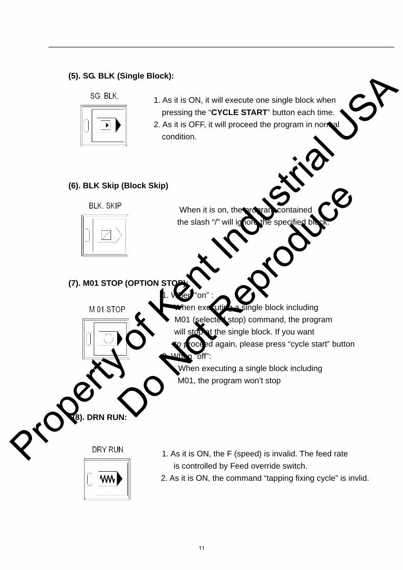
(5). SG. BLK (Single Block):
1. As it is ON, it will execute one single block when pressing the “CYCLE START” button each time.
2. As it is OFF, it will proceed the program in normal condition.
(6). BLK Skip (Block Skip) When it is on, the program contained
the slash “/” will ignore the specified block.
(7). M01 STOP (OPTION STOP): 1. When “on” : When executing a single block including
M01 (selected stop) command, the program will stop at the single block. If you want
to proceed again, please press “cycle start” button 2. When “off”: When executing a single block including
M01, the program won’t stop
(8). DRN RUN:
1. As it is ON, the F (speed) is invalid. The feed rate is controlled by Feed override switch.
2. As it is ON, the command “tapping fixing cycle” is invlid.
11
Propert
y of K
ent In
dustr
ial U
SA
Do Not
Reprod
uce
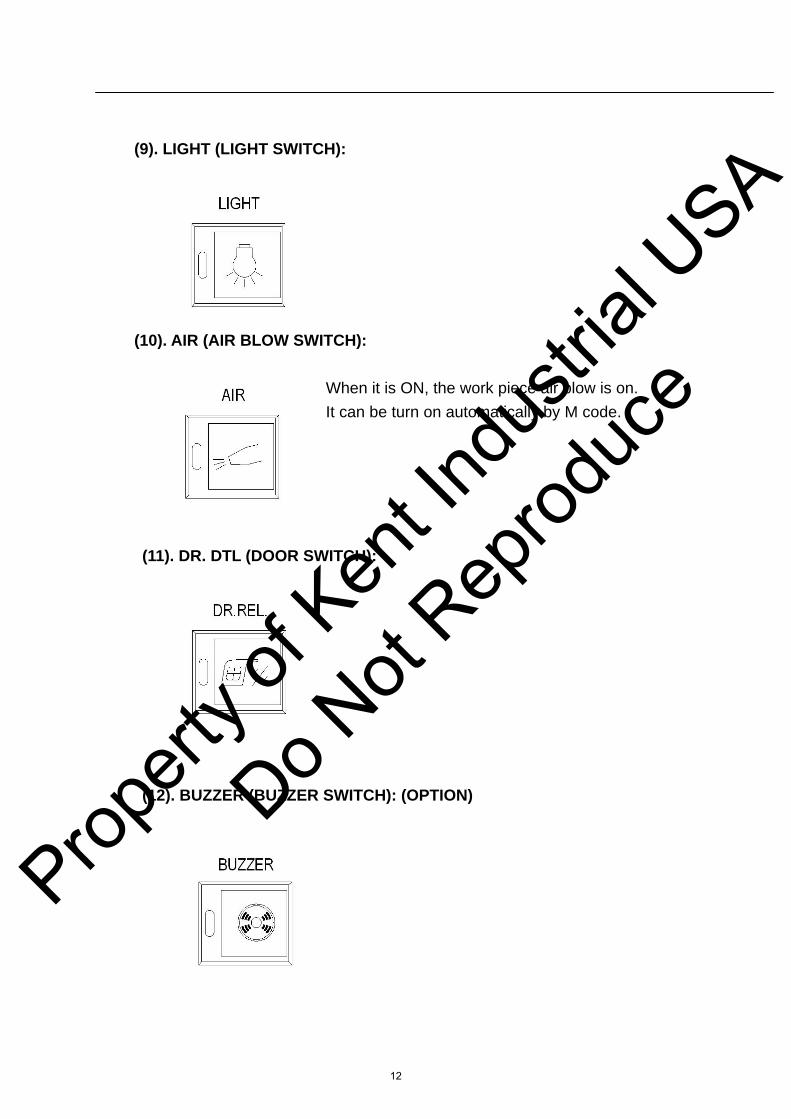
(9). LIGHT (LIGHT SWITCH):
(10). AIR (AIR BLOW SWITCH):
When it is ON, the work piece air blow is on. It can be turn on automatically by M code.
(11). DR. DTL (DOOR SWITCH):
(12). BUZZER (BUZZER SWITCH): (OPTION)
12
Propert
y of K
ent In
dustr
ial U
SA
Do Not
Reprod
uce

(13). CHIP CONVEYOR FORWARD / REVERSE SWITCH:
When program running, the chip conveyer will on automatically. It can be stop manually. when the chip is pilled up, the “BACK”
bottom can reverse the chip conveyer in order to avoid jam.
(14). ATC CW / CCW (ATC FORWARD / REVERSE SWITCH):
ATC FORWARD ATC REVERSE
Under the manual mode, the ATC will rotate in clockwise when it is ON. 1. The ATC will rotate one tool position when press each time. 2. The ATC will rotate continuously if the switch is not released.
(15). COOLANT A (COOLANT SWITCH):
1 Under manual mode (JOG, ZRN, Hx1, Hx10, Hx100), the coolant pump is enabled when it is ON. Press the switch again to disable the pump.
2. Under Auto mode (MDI, AUTO), when the switch is released, the command M08 will start the coolant pump. The command M09 will stop the coolant pump.
13
Propert
y of K
ent In
dustr
ial U
SA
Do Not
Reprod
uce

(16). COOLANT B (CHIP FLUSHING SWITCH):
When it is ON, the chip flushing system will on. The coolant will come out from the back of the chip pan.
(17). F1 (WATER GUN SWITCH):
(18). APO (AUTO POWER OFF SWITCH):
When it is ON, the machine’s power will cut off automatically after a specified time, after the program execute the M30 function.
(19). SP CW / SP STOP/ SP CCW (SPINDLE FORWARD / STOP / REVERSE): FORWARD STOP REVERSE
(20). SP ORIENT (SPINDLE ORIENT SWITCH):
14
Propert
y of K
ent In
dustr
ial U
SA
Do Not
Reprod
uce

1-13. Speed Override Switch
(1). Rapid Override Switch:
Displacement% Metric (mm) Inch (inch) Low 500.0 20.0 25 5000.0 200.0 50 10000.0 250.0 100 20000.0 787.0
(2). Feed Override Switch: Displacement% Metric (mm) Inch (inch) 0 0 0 10 2.0 0.08 20 3.2 0.12 30 5.0 0.20 40 7.9 0.30 50 12.6 0.50 60 20.0 0.80 70 32.0 1.20
80 50.0 2.00 90 79.0 3.00 100 126.0 5.00 110 200.0 8.00 120 320.0 12.00 130 500.0 20.00 140 790.0 30.00 150 1260.0 50.00
(3). Spindle Speed Override Switch:
15
Propert
y of K
ent In
dustr
ial U
SA
Do Not
Reprod
uce
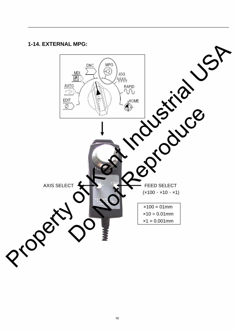
1-14. EXTERNAL MPG:
AXIS SELECT FEED SELECT (×100、×10、×1) ×100 = 01mm ×10 = 0.01mm ×1 = 0.001mm
16
Propert
y of K
ent In
dustr
ial U
SA
Do Not
Reprod
uce
Chapter 2-Warm up and Shut off
2-1 Operating Notice before warm up
1. The operators have to read this manual’s each chapters carefully and understand the special prerequisite needing attention in order to protect themselves.
2. Whether the door of the electrical box is closed or not. 3. Make sure of each operating door and the door on each side is closed or not. 4. Check the full enclosure is complete or not. 5. Check the lubrication oil is sufficient or not. 6. Check the air pressure is normal or not. 7. Check the tools, mold scale and working material is correct or not. 8. No matter in what kind of produce procedure, it should be test drive and
make sure everything is OK after changing the tool and editing the program.
17
Propert
y of K
ent In
dustr
ial U
SA
Do Not
Reprod
uce
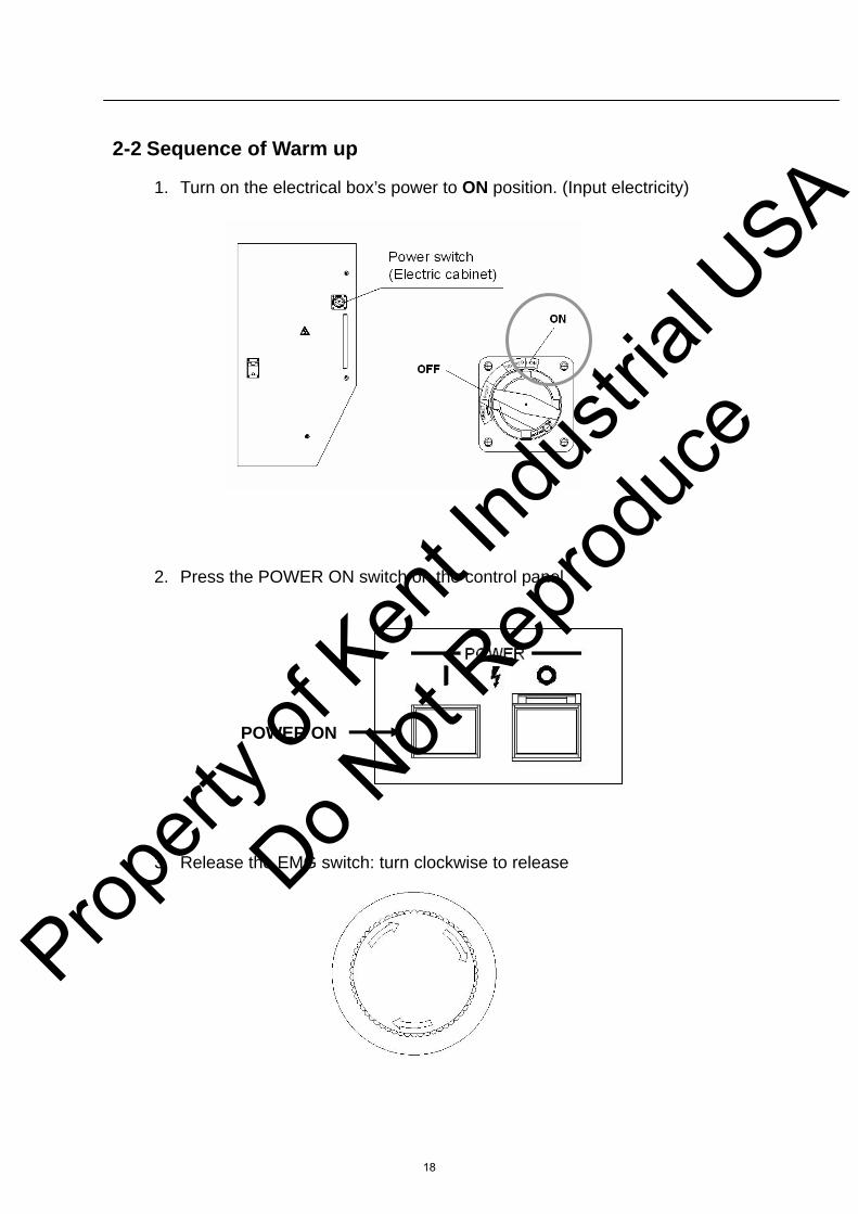
2-2 Sequence of Warm up
1. Turn on the electrical box’s power to ON position. (Input electricity)
2. Press the POWER ON switch on the control panel POWER ON
3. Release the EMG switch: turn clockwise to release
18
Propert
y of K
ent In
dustr
ial U
SA
Do Not
Reprod
uce
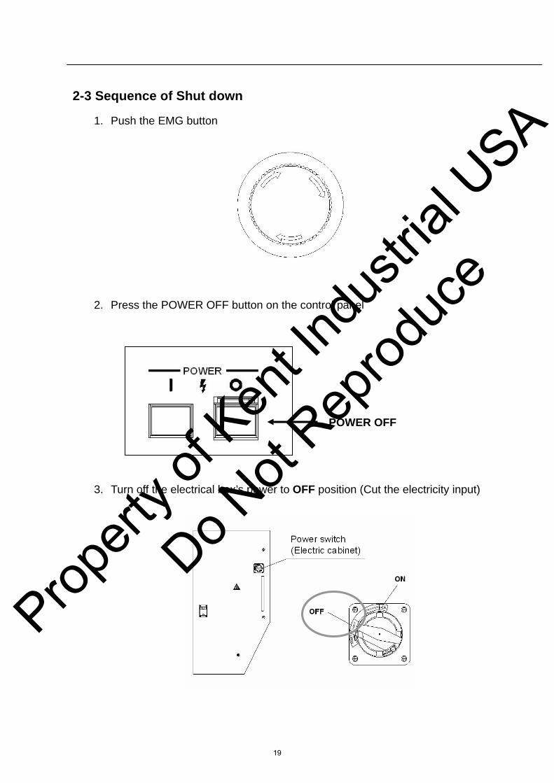
2-3 Sequence of Shut down
1. Push the EMG button
2. Press the POWER OFF button on the control panel POWER OFF
3. Turn off the electrical box’s power to OFF position (Cut the electricity input)
19
Propert
y of K
ent In
dustr
ial U
SA
Do Not
Reprod
uce
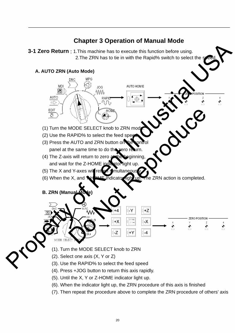
Chapter 3 Operation of Manual Mode 3-1 Zero Return : 1.This machine has to execute this function before using.
2.The ZRN has to tie in with the Rapid% switch to select the speed. A. AUTO ZRN (Auto Mode)
(1) Turn the MODE SELECT knob to ZRN mode. (2) Use the RAPID% to select the feed speed. (3) Press the AUTO and ZRN button on the control
panel at the same time to do the zero return. (4) The Z-axis will return to zero at the beginning,
and wait for the Z-HOME indicator light up. (5) The X and Y-axes will return simultaneously. (6) When the X, and Y-HOME indicator light up. The ZRN action is completed.
B. ZRN (Manual Mode)
(1). Turn the MODE SELECT knob to ZRN (2). Select one axis (X, Y or Z) (3). Use the RAPID% to select the feed speed (4). Press +JOG button to return this axis rapidly. (5). Until the X, Y or Z-HOME indicator light up. (6). When the indicator light up, the ZRN procedure of this axis is finished (7). Then repeat the procedure above to complete the ZRN procedure of others’ axis
20
Propert
y of K
ent In
dustr
ial U
SA
Do Not
Reprod
uce

3-2 MPG Mode:
1. Turn the AXIS SELECT knob to select one axis. 2. Use the MPG to move the axis
(1) Turning clockwise is toward positive. (2) Turning anticlockwise is toward negative.
3. Tie in with the H×1 / H×10 / H×100 to select the tool feed value.
Please refer the following value to make the tool feed selecting. (In accordance with the tool feed value per scale.)
(1) Metric Input (mm) H × 1 = 0.001 mm H × 10 = 0.01 mm H × 100= 0.1 mm
(2)Inch Input (inch)
H × 1 = 0.0001 inch H × 10 = 0.001 inch H × 100 = 0.01 inch FEED VALUE
AXIS SELECT
21
Propert
y of K
ent In
dustr
ial U
SA
Do Not
Reprod
uce

3-3 JOG Mode:
3-3-1. JOG FEED
(1) Turn the MODE SELECT knob to the JOG mode. (2) Turn the JOG FEEDRATE% knob to choose the Jog
speed. (3) Press the +X/+Y/+Z/+4TH button to move positive
direction. (4) Press the-X/-Y/-Z/-4TH button to move negative
direction. (5) The JOG FEED RATE% selecting depends on the
following value.
Displacement% Metric (mm) Inch (inch) 0 0 0 10 2.0 0.08 20 3.2 0.12 30 5.0 0.2 40 7.9 0.3 50 12.6 0.5 60 20.0 0.8 70 32.0 1.2 80 50.0 2.0 90 79.0 3.0 100 126.0 5.0 110 200.0 8.0 120 320.0 12.0 130 500.0 20.0 140 790.0 30.0 150 1260.0 50.0
22
Propert
y of K
ent In
dustr
ial U
SA
Do Not
Reprod
uce
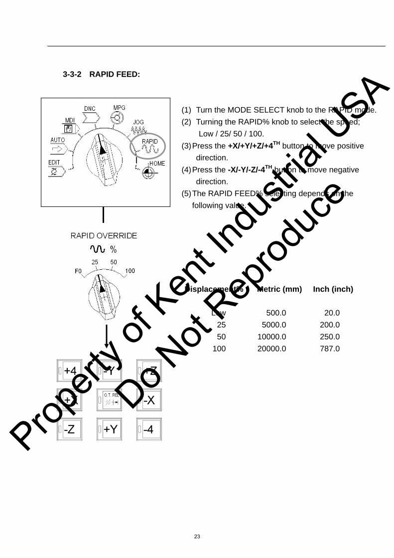
3-3-2 RAPID FEED:
(1) Turn the MODE SELECT knob to the RAPID mode. (2) Turning the RAPID% knob to select the speed;
Low / 25/ 50 / 100. (3) Press the +X/+Y/+Z/+4TH button to move positive
direction. (4) Press the -X/-Y/-Z/-4TH button to move negative
direction. (5) The RAPID FEED% selecting depends on the
following value.
Displacement% Metric (mm) Inch (inch) Low 500.0 20.0 25 5000.0 200.0 50 10000.0 250.0 100 20000.0 787.0
23
Propert
y of K
ent In
dustr
ial U
SA
Do Not
Reprod
uce

3-4 Manual Mode of Spindle Running
1. Mod e select: it should be under JOG, ZRN, MPG, manual mode 2. Press the FORWARD button, and then the spindle will turn clockwise. 3. Press the SPINDLE STOP button, and then the spindle will be stopped. 4. The adjustment of spindle’s speed:
(1) Mode select: MDI mode (2) Input the spindle speed “S” value, which is the basic value as 100%. (3) The spindle speed could be adjusted by turning the SPINDLE% knob. (4) The speed rate is range from 50% to 120% (5) It is NOT ALLOWED to touch the spindle, while it is running, to avoid the
harm of the operator.
24
Propert
y of K
ent In
dustr
ial U
SA
Do Not
Reprod
uce
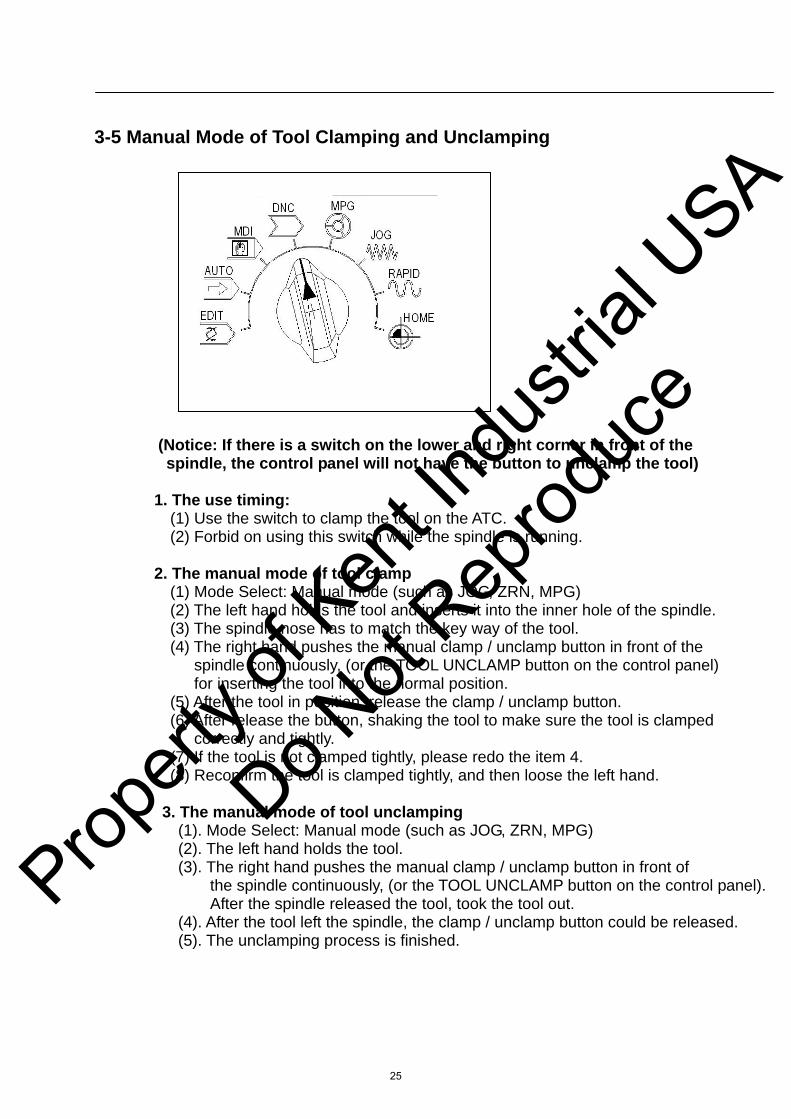
3-5 Manual Mode of Tool Clamping and Unclamping
(Notice: If there is a switch on the lower and right corner in front of the spindle, the control panel will not have the button to unclamp the tool)
1. The use timing:
(1) Use the switch to clamp the tool on the ATC. (2) Forbid on using this switch while the spindle is running.
2. The manual mode of tool clamp
(1) Mode Select: Manual mode (such as JOG, ZRN, MPG) (2) The left hand holds the tool and inserts it into the inner hole of the spindle. (3) The spindle nose has to match the key way of the tool. (4) The right hand pushes the manual clamp / unclamp button in front of the
spindle continuously, (or the TOOL UNCLAMP button on the control panel) for inserting the tool into the normal position.
(5) After the tool in position, release the clamp / unclamp button. (6) After release the button, shaking the tool to make sure the tool is clamped correctly and tightly.
(7) If the tool is not clamped tightly, please redo the item 4. (8) Reconfirm the tool is clamped tightly, and then loose the left hand.
3. The manual mode of tool unclamping
(1). Mode Select: Manual mode (such as JOG, ZRN, MPG) (2). The left hand holds the tool. (3). The right hand pushes the manual clamp / unclamp button in front of
the spindle continuously, (or the TOOL UNCLAMP button on the control panel). After the spindle released the tool, took the tool out.
(4). After the tool left the spindle, the clamp / unclamp button could be released. (5). The unclamping process is finished.
25
Propert
y of K
ent In
dustr
ial U
SA
Do Not
Reprod
uce