OPERATION AND SAFETY - Go-Devil Manufacturers of Louisiana
34
GO-DEVIL Since 1977 · U.S. Patent Des. 259488 ― INSTRUCTIONS ― Operation and Service Manual Revised April 2016 GO-DEVIL ® Manufacturing Company of Louisiana LLC (225) 752-0167 • Toll Free 1-888-490-3254 • Fax (225) 752-0175 18649 Womack Road • Baton Rouge, LA 70817 Please visit our website at www.godevil.com ®
Transcript of OPERATION AND SAFETY - Go-Devil Manufacturers of Louisiana

GO-DEVIL Since 1977 · U.S. Patent Des. 259488
― INSTRUCTIONS ―
Operation and Service Manual
Revised April 2016
GO-DEVIL® Manufacturing Company of Louisiana LLC
(225) 752-0167 • Toll Free 1-888-490-3254 • Fax (225) 752-0175
18649 Womack Road • Baton Rouge, LA 70817
Please visit our website at www.godevil.com
®
OPERATION AND SAFETY
1. GASOLINE IS EXTREMELY FLAMMABLE! Always handle in properly approved containers. Do not fill tank while engine is hot or running! Spilled fuel could ignite if it comes in contact with hot engine or sparks!
2. DO NOT LEAVE REMOTE FUEL TANK ON 16 - 35 HP ENGINES
CONNECTED WHEN NOT IN USE! The fuel tank will build pressure from the sun and will force fuel through the carburetor and into the crankcase. At this point the crankcase will become over full and will blow oil into the air cleaner from the breather. After the air cleaner becomes saturated with oil, the fuel mixture becomes too rich and will foul the spark plugs.
3. KEEP HANDS, FEET, HAIR, AND CLOTHING AWAY FROM ANY MOVING
PARTS to prevent accidents while engine is running both in the water and, most importantly, while on land!
4. NEVER TOUCH ENGINE COMPONENTS DURING OR IMMEDIATELY AFTER
OPERATION. Components can become extremely hot which could result in severe burns!
5. NEVER RUN YOUR GO-DEVIL IN AN ENCLOSED AREA! Exhaust gasses contain poisonous carbon monoxide! Always test run in a well ventilated area.
6. ALWAYS ATTACH A SAFETY ROPE FROM THE RIB IN YOUR BOAT TO THE
HANDLE OF YOUR GO-DEVIL BEFORE OPERATION! This enables you to run your engine in a neutral position! (See Page 2)
7. ALWAYS OPERATE YOUR GO-DEVIL WITH THE SAFETY KILL SWITCH
ATTACHED TO YOUR WRIST OR BELT LOOP! After warm up, always test your safety kill switch to make sure it is operating properly!
8. OPERATE YOUR GO-DEVIL FROM A SITTING POSITION, unless you install a grab bar in your boat to operate standing up!
Before ordering parts for your motor, please make sure you have the model
number and serial number that is stamped into the steering plate under the u-
joint. The serial number denotes what parts are required for your motor and you
cannot purchase parts without this number. Please have your boat hull I.D.
number to purchase boat parts. The hull I.D. number is stamped under the boat
handle welded onto the transom of the boat.

TABLE OF CONTENTS Operation and Safety
Assembly, Operation, and Adjustments Page 1-4
Lubrication Page 5
Storage Page 6
Maintenance Checklist Page 7
Propeller Wear Page 7
Propeller Adjustments Page 7
Seals – Lower (Maintenance) Page 8
Bushings - Lower (Checking Wear) Page 8
Fuel Tank Page 8
Lubricator Maintenance Page 8
Tools - Service Pages 9 & 24
Propeller – Removal and Installation Page 10
Seals - Lower (Replacement) Pages 11 & 12
Shaft - Removal (units with Split Yokes) Page 13
Shaft Installation (units with Split Yokes) Page 13
Shaft - Removal (units without Split Yokes, using our tools) Page 14
Shaft – Removal (units without Split Yokes, not using our tools) Page 15
Bushings – Removal and Installation Page 16
Bushings – Line Boring (units shipped before August 2001) Page 18
Shaft – Installation (units without Split Yokes) Page 19
Engine Replacement Page 20
Bushing - Alignment Page 21
U-Joint Disassembly and Assembly Page 22
Parts Drawing (units shipped before August 2001) Page 23
Parts Drawing of New Seal System (units shipped after August 2001) Page 24
Parts Drawing of New Seal System (7/8” shafts, 31-35hp) Page 25
New Seal System Retrofit (for units sold before June 2001) Page 26
Handle Installation Page 28
Throttle Attachment Page 29
Warranty Service Record
INSTRUCTIONS
Dear Customer, You have just purchased one of the toughest pieces of equipment ever built. The GO-DEVIL will give you many years of service with very little maintenance. Of the few problems that occur, most are due to dirty fuel or not running the engine out of fuel at the end of the season. We have found that the unleaded fuels will gum up the carburetor in a few months if your engine is not in use. We recommend using a fuel stabilizer such as Briggs & Stratton part number 100117 in your tank of fuel before
storage. Then turn off the fuel valve or disconnect the fuel hose and run engine
completely out of fuel!
ASSEMBLY, OPERATION AND ADJUSTMENTS
1. Remove handle from frame by cutting plastic tie-wraps that have not been trimmed.
2. Remove the engine cover on crate with a hammer or cut the 2X4’s with a saw to
access the GO-DEVIL.
3. Cut the metal band on the shaft with tin snips or pull with a claw hammer.
4. Loosen the engine clamp from the crate with a Crescent wrench or 1 1/16 wrench or socket (15/16 wrench for galvanized models).
5. Lift the GO-DEVIL out of the crate and install it on the transom of your boat. Tighten the transom clamp very tight, through bolts are not necessary.
6. Locate the four handle bolts under the engine. Remove the nuts from the bolts and install the handle. Tighten the bolts until there is no more up and down movement in the handle. See PAGE 28
7. Route the throttle cable to the engine connection and attach as pictured on PAGE 29-30. Check to make sure that you get full travel of the throttle.
8. To attach the kill switch wire, follow the throttle cable until the kill switch wire ends. (They are tied parallel to each other.) The terminal will be near the end of the wire on all models. Continued on next page.
PAGE 1

ASSEMBLY, OPERATION AND ADJUSTMENTS CONT’D
9. Tie a rope to the rib in your boat under the hand grip of the GO-DEVIL and put a loop in the rope. Slip the loop over the handle to hold the engine in a neutral position. (Shaft horizontal, with the prop above the water when the boat is in the water.) (See Photo Below)
10. Fill the crankcase with the recommended amount and type of oil. With the engine held perfectly level check the oil level with the dip stick. Engines equipped with low oil shutdown (5.5hp Honda, 9hp Honda, 20hp Honda, 24hp Honda, 5.5hp Vanguard, 6hp Vanguard, and 9hp Vanguard) will not run if the oil level is slightly low on the Go-Devil, since it tilts. Use a high detergent motor oil of the same viscosity you are using in your car or truck for that time of the year. In warm temperatures we recommend to use straight 30 weight oil, this will reduce oil consumption.
11. If your engine is equipped with electric start, connect the battery cables to the
battery. Attach the red cable to the positive (+) side of the battery and attach the black
cable to the negative (-) side of the battery. 37 hp engines need to have nylon insert
nuts installed on the battery terminals instead of wingnuts. Check to make sure
the battery cables are tight at all times to avoid damaging the EFI computer.
12. Fill the fuel tank with clean, fresh gasoline from a clean fuel can. If your engine is equipped with a fuel pump (16hp or larger) connect the fuel hose to your fuel tank and pump the bulb until firm. You are now ready to start the engine. Continued next page.
PAGE 2

ASSEMBLY, OPERATION AND ADJUSTMENTS CONT’D
13. To start the engine, first pull the choke, now pull rope or use electric starter if so equipped. Electric start engines are equipped with an electronic tilt switch for safety! These engines will not start with the prop in the water or if the shaft is not horizontal! It may be necessary to run on choke or half choke for a few seconds until engine warms up. You should run the engine for at least 10 minutes to check it out. If the engine runs rough after warm up the carburetor may need adjustment. (Refer to engine manual)
14. The adjustment bolt on the rear of the transom clamp should not be adjusted or replaced with a longer bolt. This bolt is set at the factory with a 5/8” x 2” long bolt. Any adjustment to the bolt or using a longer bolt will result in damaging your frame. This bolt should not be touching in an on plane situation!
15. We recommend using a good nylon rope to tie your boat instead of a boat strap. Tie the rope to the trailer frame on one side of the boat even with the hand grip. Bring the rope over the boat and make a wrap around the handle, behind the grip on the Go-Devil, then pull a loop in the rope before the rope comes down the side of the boat. Bring the rope around the trailer frame and back up to the loop, cinch the rope tight and tie it off. This procedure will hold your boat as tight as any boat strap and will secure your Go-Devil so it will not bounce down the road when trailering. We also recommend that you tie a red flag to the tail when towing your boat down the highway. See photo below.
16. When launching your boat always leave the handle rope secured in the neutral position (shaft horizontal). This also applies when starting engine. Continued next page.
PAGE 3

ASSEMBLY, OPERATION AND ADJUSTMENTS CONT’D
17. Before starting the engine always put on your life jacket as you would in any boat with any engine. Attach the safety kill switch to your belt loop or wrist. You are now ready to start the engine. As before, let the engine warm up for a few minutes, set the throttle at idle, drop the rope from the handle and hold firmly. Now lower the prop into the water. It will be necessary to control the prop depth at idle or slow speeds with your hand. You are now ready to speed up the throttle and get up on plane. Use extreme caution in operating your Go-Devil for the first few days so you can get the feel of it. Do not make sharp turns at wide open throttle, always slow down. In shallow water it will be necessary to control the depth of the prop by hand because it will have a tendency to dig in the bottom. Always remember the Go-Devil makes maximum thrust with the prop right under the surface in the mud, when you are in virtually no water.
18. When you are running at top speed with a light load, the cavitation plate above the prop should be running just under the surface of the water. If it is coming out of the water, take a 12” Crescent wrench and bend the rear of the plate up (the flat space between the 45 degree bends). If the plate is running too deep bend the plate down as needed. Only bend the cavitation plate about 1/8” up or down and then run it again to check performance. If needed, bend more and check again until the cavitation plate stays just under the surface of the water on plane. See photo below.
PAGE 4

LUBRICATION
1. CHECK ENGINE OIL BEFORE EACH USE.
2. a) Lubrication for units with upper ball bearing shipped after August 2001: NEVER
GREASE THE FITTING ON THE LUBRICATOR!!! Lubricate the fitting in the middle of the shaft before each use or every 8 hours of running time. Fill until the piston in the pressure lubricator moves to the top with #1 or #2 waterproof grease such as AQUA-LUBE. The #1 grease is recommended for colder temperatures. This procedure ensures that the housing is full. This should only take a few pumps on the gun. If this procedure takes more than ten pumps at two different times, it may be necessary to replace the lower seals.
When your Go-Devil starts to use an excessive amount of grease, it is time to replace the lower seals! DO NOT DELAY THIS PROCEDURE!!! If this procedure is delayed, premature wear will be caused to the shaft and lower bushing due to the lack of lubrication!!! THE LOWER SEALS AND WEAR ON THE SHAFT AND BUSHINGS ARE NOT COVERED BY WARRANTY!!! THE LIFE OF THE SHAFT AND LOWER BUSHINGS IS DETERMINED BY THE LIFE OF THE LOWER SEALS! The life of the lower seals is determined by how the shaft is lubricated and how abrasive the material is that you are running in, such as mud, sand, and silt. We recommend replacing the lower seals at least once a year or as often as required. Under extensive or commercial use, especially in brackish or salt water, it will be necessary to replace more often.
b) For Go-Devils shipped after February 1, 1997, and before August 2001, equipped with pressure lubricator: Visually inspect lubricator for grease consumption and
lubricate before each use by pumping grease into the fitting in the middle of the shaft
until the lubricator is ¾ full of grease using #1 or #2 waterproof grease such as AQUA-LUBE. Lubricator should move down during operation. If it does not move, it will be necessary to remove it and check to see if it expels grease. If it does, reinstall it; if it does not; clean it thoroughly and check again. If it still does not expel grease, then it
must be replaced. IT IS THE CUSTOMER’S RESPONSIBILITY TO CHECK AND
INSURE THAT THE LUBRICATOR IS WORKING PROPERLY. It is not required to loosen the top seal assembly as it was on Go-Devils shipped prior to February 1, 1997.
NEVER GREASE THE FITTING ON THE LUBRICATOR!!! If the lubricator has not moved down after operation of the Go-Devil, it will be necessary to check the lubricator by pumping grease into the fitting on the shaft. This will fill the shaft and the lubricator. The lubricator can not be damaged by over-lubricating it. It will expel grease out of the top of it as it was designed to do. During operation of your Go-Devil, the rotation of the shaft in the surrounding grease will create friction and heat. This will cause the grease to expand and will sometimes expel grease out of the top of the lubricator. This situation is normal. When your Go-Devil starts to use an excessive amount of grease, it is time to replace the lower seals! DO NOT DELAY THIS PROCEDURE!!! If this procedure is delayed, premature wear will be caused to the shaft and lower bushing due to the lack of lubrication!!! Continued on next page.
PAGE 5
THE LOWER SEALS AND WEAR ON THE SHAFT AND BUSHINGS ARE NOT COVERED BY WARRANTY!!! THE LIFE OF THE SHAFT AND LOWER BUSHING IS DETERMINED BY THE LIFE OF THE LOWER SEALS! The life of the lower seals is determined by how the shaft is lubricated and how abrasive the material is that you are running in, such as mud, sand, and silt. We recommend replacing the lower seals at least once a year or as often as required. Under extensive or commercial use, especially in brackish or salt water, it will be necessary to replace them more often.
c) For Go-Devils shipped before February 1, 1997, not equipped with pressure lubricator: Lubricate the fitting on the shaft housing every 4 hours of running time or before each use. The upper seal collar must be completely unscrewed before lubrication. We recommend#1 or #2 waterproof grease. Pump grease in fitting until it
comes out around drive shaft. This collar must be installed hand tight only! The grease in the shaft will expand during operation, from the friction of the turning shaft. This will cause grease to seep out around the threads of the seal collar. When lubricating the shaft, you are replacing the seepage and any grease that may have leaked out of the lower seals. If your Go-Devil begins to use an excessive amount of grease, it will be necessary to replace the lower seals.
THE LIFE OF THE SHAFT AND LOWER BUSHING IS DETERMINED BY THE LIFE
OF THE LOWER SEALS. The life of the lower seals is determined by how abrasive the material is that you run in such as mud, sand, and silt. 3. Grease the other four fittings every fourth time you grease the shaft, any more often will be excessive and messy. These fittings are located on the upper bearing, universal joint, between the steering plates and on the bracket shaft. Apply a small amount of grease to the transom clamp bolts yearly or as needed. 4. We recommend changing engine oil every 50 hours or yearly. When changing oil, run engine to heat oil before draining. When changing oil filter (if equipped) always fill filter with oil before installing. Fill crankcase, then spin engine with the electric starter for about one minute with the safety kill switch lanyard removed, to prime oil pump. Start the engine and let idle for a few minutes before speeding.
STORAGE 1. Lubricate all fittings on your Go-Devil. 2. Touch up any spots where the paint is scratched or worn off to prevent rusting. 3. Add a fuel stabilizer (Briggs & Stratton part #100117) to the fuel and run the engine for 10 minutes to circulate stabilizer into carburetor. Turn off fuel or disconnect hose
and run engine out of fuel. DO NOT LEAVE FUEL IN THE CARBURETOR OVER 30
DAYS. UNLEADED FUEL TURNS TO VARNISH AND WILL RUIN THE
CARBURETOR. Continued on next page.
PAGE 6

4. Remove the spark plugs and put a tablespoon of engine oil into each cylinder. Reinstall the spark plugs, then turn the engine over with the starter to distribute the oil. 5. Spray the engine with WD40 or equivalent to prevent corrosion. 6. If possible, store your Go-Devil inside to protect it from sunlight. If you store it outside do not store it with plastic or visqueen tied around the engine. This will cause the engine to sweat. We recommend using canvas or the bottom third of a plastic drum. This will shed sunlight and let the engine breathe and not sweat.
MAINTENANCE CHECKLIST AND ADJUSTMENTS
BOLTS
All bolts in your Go-Devil frame should be checked annually for tightness (more often with severe usage); especially the two upper rear engine bolts. If these bolts come loose it could cause premature wear to the upper bushing. As the steering plates wear it will be necessary to tighten the ¾” steering bolt to take up the tolerance. DO NOT over tighten to the point that there is friction when the Go-Devil is steered out of the water. It must steer freely in this position.
PROPELLER WEAR
After running your Go-Devil several times, begin inspecting the propeller for wear. To do this, measure the blades on your propeller from end to end. (EXAMPLE: A 9 X 6 prop is 9” in diameter when new. An 8 X 5 prop is 8” in diameter when new.) We recommend purchasing a new propeller once it has worn by ½” in diameter. We warrant new propellers against cracking and breaking. When we replace a cracked propeller during the warranty period, we will charge for the wear towards the replacement propeller.
PROPELLER ADJUSTMENTS The propeller on your GO-DEVIL is threaded and screws on to the drive shaft. The propeller must run in a floating position. The propeller tolerance should be checked monthly. The end of the blade should move two to four inches from left to right after it has been operated under normal conditions (example from 12:00 to 2:00). If the propeller runs too loose it will cause premature wear of the shaft threads. If the prop needs tightening, remove the rear nylon jam nut and lock washer. Tighten the prop and remaining jam nut hand tight. Reinstall the lock washer and nylon jam nut. Tighten the nylon jam nut as tight as possible using a socket or combination wrench. DO NOT USE AN IMPACT GUN! After usage the prop should loosen slightly as required. As the prop leaves and enters the water during operation, you may hear a popping or cracking sound in the front of the engine. This sound is the propeller floating on the drive shaft, which is normal. Sometimes there is a vibration at an RPM just above idle, this is also normal.
PAGE 7

MAINTENANCE CHECK LIST and ADJUSTMENTS CONTINUED
LOWER SEALS The life of your seals determines the life of your shaft and lower bushing. The material you are running in determines the life of your seals. For example sand and fine sediment will wear seals much faster than humus or aquatic vegetation because it is more abrasive. When you lubricate your shaft, you are replacing the grease that leaked out due to heat expansion. This should not be more than four to ten pumps on a hand grease gun. When your Go-Devil starts consuming more than this amount it is time to replace the lower seals. Before disassembly, check for lower bushing wear. New seals will not reduce the grease consumption if the lower bushing is worn.
LOWER BUSHING WEAR Check your Go-Devil for lower bushing wear. Hold the cavatation plate with one hand. With the other hand move the propeller up and down then left to right. If no movement is felt, there is no wear in the bushing. Once the movement becomes 1/16” or more, it will be necessary to replace the bushing and possibly the shaft.
FUEL TANK
Drain your fuel tank of water and trash yearly. To drain the tank, lean your Go-Devil or fuel tank so one corner is lower than the other. Use a siphon hose to siphon at the bottom of the lowest corner. This procedure is much more effective than turning the tank over and shaking it and will remove all water and trash. Keep the gas tank unplugged when not in use. (See Operation & Safety #2)
LUBRICATOR MAINTENANCE We recommend cleaning the pressure lubricator on your Go-Devil yearly. To disassemble the lubricator, unscrew the top one-quarter turn to remove the top and spring. Next, pump grease into the shaft housing on the Go-Devil to push the piston out. Wipe the piston and plastic housing thoroughly with a paper towel. If necessary, use soap and water. Do not use a petroleum solvent such as gasoline, varsol, kerosene, thinner, or carburetor cleaner. These solvents will destroy these components! After cleaning, install the piston and stretch the spring a little to give it a little more tension. Insert the spring and align the cap and screw on one-quarter turn. Pump grease into the shaft housing to fill the lubricator to ¾ full.
PAGE 8

TOOLS
SPECIAL TOOLS TO SERVICE GO-DEVILS
PART # DESCRIPTION USED FOR PRICE
PW2-3BL PROP WRENCH PROP REMOVAL $50
SHBUPU PULLER FOR SHAFT & BUSHINGS
(SLIDE HAMMER)
USED WITH: SHAFT ADAPTER TO REMOVE SHAFT-(MUST HAVE SHIMS WEDGED BETWEEN YOKE AND UPPER SEAL ASSY SO ONLY SHAFT WILL BE REMOVED.) BUSHING PULLER- TO REMOVE BUSHING-(MUST USE 7/8” TAP TO THREAD INNER BUSHING FOR BUSHING PULLER INSERTION.)
$50
SHAD SHAFT ADAPTER USED WITH PULLER TO REMOVE SHAFT $15
BUPU BUSHING PULLER USED WITH PULLER TO REMOVE BUSHING $20
SU1 SHIM 1” THICK (This part is not needed for a new seal system/split yoke.)
USE THIS SHIM FIRST-WEDGED BETWEEN YOKE & UPPER SEAL ASSY. WITH NEEDED ADDITIONAL SHIMS IN ORDER TO REMOVE THE SHAFT WITHOUT DISTURBING THE YOKE ASSEMBLY.
$5
SH125 SHIM .125” THICK (This part is not needed for a new seal system/split yoke.)
ADDITIONAL SHIMS TO USE WITH 1” SHIM (10 @ $10)
$10
BUIN BUSHING INSTALLER TO INSTALL BUSHINGS $10
T78 7/8” TAP USED TO THREAD INNER BUSHING FOR INSERTION OF BUSHING PULLER FOR REMOVAL OF BUSHING.
$30
R34 3/4” REAMER AFTER BUSHING INSTALLATION, USED TO REAM THE BUSHING FOR PROPER SHAFT PLACEMENT/FIT.
$90
TOTAL $280.00 These tools can be rented for $20.00 plus shipping with a $300.00 deposit.
OTHER TOOLS NEEDED TO SERVICE GO-DEVILS 18” PIPE WRENCH 1/2” DRILL 8” OR 10” CRESCENT WRENCH 1 1/16” SOCKET OR COMBINATION WRENCH 1 1/8” DEEP SOCKET OR COMBINATION WRENCH PAIR OF CHANNEL LOCK PLIERS 4 TO 5 LB HAMMER 5/16” DRILL BIT 3/4” 10 TPI DIE NUT 3/4” 10 TPI TAP
PAGE 9
PROPELLER REMOVAL 1. Place a large screwdriver or shaft through the lower half of the universal joint. This will prevent the drive shaft from turning. DO NOT PLACE SCREWDRIVER THROUGH UPPER HALF OF THE UNIVERSAL JOINT. THE GREASE FITTING WOULD BE SHEARED OFF! 2. Remove the nuts and washers located behind the propeller. (Right hand threads) 3. Using prop wrench, (PW2-3BL) unscrew prop. If prop wrench is not available, use a large pipe wrench, with the sides of the jaws touching the end of the propeller blades, unscrew prop. If the prop is stuck, as they usually are, pull very hard. DO NOT STRIKE THE ENDS OF THE BLADES TO BREAK IT FREE-THIS NEVER WORKS. The shaft is like a torsion bar and will absorb the shock. If you can not break the prop free, heat the front of the hub red hot. This will only damage the seals. If the prop is still stuck: Remove the shaft with the prop. Place the shaft, (ahead of where the bushing rides), in a pipe vice. This will eliminate the spring action in the shaft. Using the same steps as above, unscrew the prop. It may be necessary to reheat the hub. Remove any scars on the shaft that the vice created with a smooth mill file.
PROPELLER INSTALLATION 1. Inspect the forward jam nut and forward brass washer, replace if necessary. It may be necessary to run a die nut (3/4” 10 TPI) over the threads of the shaft to clean them. It may also be necessary to run a tap (3/4” 10TPI) through the propeller. 2. Apply never-seize to the shaft. Screw the prop on to the shaft clockwise (right hand threads). When installing a used propeller use caution, the blades may be very sharp from wear. Use leather gloves to prevent injury. 3. Install the rear brass washer (BW) followed by the jam nut (1A2). The prop and jam nut should be installed finger tight. Install the 3/4” lock washer (1A3), followed by the 3/4” nylon insert jam nut (1A4). The nylon insert jam nut should be tightened as tight as possible. DO NOT USE AN IMPACT GUN! After operating your Go-Devil under normal conditions, the prop will become loose on the shaft. This will allow the prop to float on the shaft. It should float 2”-4” at the tip of the blade or 12:00 to 2:00 clock positions. (See PAGE 7 PROPELLER ADJUSTMENTS for specifications.)
PAGE 10

LOWER SEAL REPLACEMENT For units with upper ball bearings sold after August 2001
(Refer to PAGE 24.) 1. Determine if lower bushing should also be changed. (Refer to PAGE 8 LOWER BUSHING WEAR) 2. Remove the propeller. (Refer to PAGE 10 PROPELLER REMOVAL) 3. Remove the brass washer (BW) and forward jam nut. 4. Remove lower housing cap (LHC – which has left hand threads.) (Must turn clockwise to remove). Clean thoroughly of any grease or Loctite. 5. Pick old seals out with a tool such as an ice pick with 90 degree bend on the end. *If you removed the lower seal housing (LSHS15) clean any old RTV sealant and reapply silicone to the leading inside lip before screwing the housing back on to the frame. Remove any excess sealant inside the lower seal housing because any excess sealant can plug the grease channel in the lower bushing. 6. Pack the first seal with grease and insert it into the housing with the spring-side facing the engine by screwing the seal on over the threads on the shaft (or using a split plastic sleeve to slide over threads). These seals can be pushed in with a 1” plastic pipe. This procedure may shave a small amount of material off of the outside diameter of the seal. Insert the next seal in with the spring facing the prop. Pack the area between seals with grease. 7. Install new scraper seal into the lower housing cap (LHC) and apply blue Loctite to the threads. Install the cap onto the lower seal housing (LSHS-15) by turning it counter-clockwise (left-hand threads). 8. Install the propeller as shown on PAGE 10.
PAGE 11

LOWER SEAL REPLACEMENT for units sold before August 2001
1. Determine if lower bushing should also be changed. (Refer to PAGE 8 LOWER
BUSHING WEAR.)
2. Remove the propeller. (Refer to PAGE 10 PROPELLER REMOVAL.) 3. Remove the brass washer (BW34 or BW78) and forward jam nut (1A116-25 or 1A1-78). Unscrew lower shaft seal assembly (right hand threads). Using a screwdriver, remove old seals. 4. Clean the inside of the seal housing and install the new seals as shown below.
AFTER SEALS ARE INSTALLED IN HOUSING, PACK WITH GREASE. 5. Install the shaft seal assembly by screwing it on over the threads. DO NOT PUSH IT OVER THE THREADS, THIS COULD DAMAGE THE SEALS! 6. Start the shaft seal assembly by hand and screw it on being careful not to cross thread it on the pipe. Using a pipe wrench tighten it very tight. Do not tighten the assembly so tight that the front swells over the pipe. IF THE ASSEMBLY COMES LOOSE, IT WILL JAM AGAINST THE FORWARD JAM NUT AND LOCK UP THE DRIVE SYSTEM!
7. Now install all nuts, washers, and prop. (Refer to PAGE 10 PROPELLER
INSTALLATION.)
PAGE12

SHAFT REMOVAL ON UNITS WITH SPLIT YOKES 1. Leave the engine mounted on your boat in the trailering position or clamped to a solid saw horse. Remove propeller, all nuts and washers. (Refer to PAGE 10 PROPELLER REMOVAL.) 2. Cut the tie wire holding the set screw in the lower yoke and remove the set screw. DO NOT REMOVE THE SET SCREWS FROM THE ENGINE YOKE! 3. Remove the bolt in the split yoke with two 9/16” wrenches. Drive a screwdriver into split on yoke as parallel to the shaft as possible. DO NOT DRIVE IN PERPINDICULAR OR AT RIGHT ANGLE TO SHAFT! 4. If equipped with an upper ball bearing, loosen set screw on eccentric collar. Now, loosen eccentric collar clockwise (standing from rear) using 1/8” pin punch of center punch. 5. Screw on propeller by hand and tap on propeller with rubber or rawhide hammer and bump shaft out.
SHAFT INSTALLATION ON UNITS WITH SPLIT YOKES 1. Slide shaft through housing slowly until it comes out of the upper bushing or upper bearing housing. If equipped with upper bearing, slide shaft through bearing and slip the eccentric collar over the shaft leave loose. 2. Install the shaft key ¾ of the way into the yoke and slide the shaft to the yoke with a pair of channel locks. Now drive the shaft in about ¾” with a ¾” coupling nut or our shaft puller. At this point, remove the lubricator and fill the tube with grease until grease comes out at the fitting. Now install a 1/8” pipe plug and finish filling the tube slowly until grease starts coming out of the lower bushing. At this time we recommend removing the pressure lubricator and taking it apart and cleaning it thoroughly. Use paper towels or soap and water, no solvents. Stretch the spring to insure proper pressure. 3. Now install the lower seal housing per instructions on PAGE 11 or PAGE 12, whichever applies to your unit. Install the forward jam nut (1A116-25) tightly. Now drive the shaft in until you have 1/8” to 3/16” air gap between the forward jam nut and the LHC. You will have to insert a large chisel into the lower yoke to prevent the key from sliding up. 4. Countersink the set screw hole in the split yoke with a 5/16” drill bit. Tighten the bolt on the yoke at this time using two 9/16” wrenches extremely tight. Install the set screw and tie with safety wire. Fill pressure lubricator until ¾ full. You are now ready to install the propeller.
PAGE 13
SHAFT REMOVAL
ON UNITS WITHOUT SPLIT YOKE USING OUR TOOLS
1. Leave the engine mounted on your boat in the trailering position or clamped to a solid saw horse. Remove propeller, all nuts and washers.
(Refer to PAGE 10 PROPELLER REMOVAL) 2. Cut the tie wire holding the set screws in the lower yoke and remove the set screws. DO NOT REMOVE THE SET SCREWS FROM THE ENGINE YOKE! 3. Tighten seal collar (#8) on upper seal housing with a pair of channel lock pliers. Take a 1” shim (#SH1) and as many .125 shims (#SH125) as needed to fill the space between the lower yoke (#11) and the seal collar (#8). After installing the shims, unscrew the seal collar (#8) until it compresses all the shims. This enables you to pull against the frame and not the engine. It is important to use as many shims as possible to pull against as many threads on the shaft housing as possible. 4. Using the shaft puller (#SHBUPU) with the shaft adapter (#SHAD) installed, screw the assembly to the propeller end of the drive shaft. Using the slide hammer on the puller, remove the drive shaft. 5. After the drive shaft comes out of the yoke, remove the square key from the shaft. The key must be removed before it hits the seal. The key will be a tight fit in the shaft
and yoke. The shaft and yoke are a press fit! DO NOT FILE THE KEY TO MAKE IT A
SLIP FIT. IF THE SHAFT IS A SLIP FIT, THIS CONNECTION WILL FALL APART!! Our shaft key is under size so if for some reason your shaft is not a press fit, we can supply you with an oversize key to make it a press fit. (Part #13-8) 6. Completely remove the drive shaft. 7. Inspect the shaft for wear, at the bottom where the bushing runs. Replace the shaft if worn or rusted where the lower seal runs. Also inspect the shaft key way for cracks - replace if cracked. Sometimes there will be a groove in the center of the shaft. This is caused by the grease fitting and is not a problem.
PAGE 14
SHAFT REMOVAL ON UNITS
WITHOUT SPLIT YOKE WITHOUT USING OUR TOOLS
ITEMS NEEDED 2 3/4” flat washers 1 piece of 1” pipe 2” long (steel) 1 large punch such as a 3/4” X 12” shaft 1 3 to 4 pound hammer 1. Leave the engine mounted on your boat in the trailering position or clamped to a solid saw horse. Remove propeller, all nuts and washers. (Refer to PAGE 10 PROPELLER REMOVALS) 2. Cut the tie wire holding the set screws in the lower yoke and remove the set screws. DO NOT REMOVE THE SET SCREWS FROM THE ENGINE YOKE! 3. Slide a 3/4” flat washer over the lower end of the drive shaft against the lower seal collar assembly. Slide a piece of 1” pipe X 2” long over the shaft and against the 3/4” flat washer. Slide the second 3/4” flat washer over the shaft and against the 1” pipe. Screw on one of the prop nuts (not the nylon insert nut), this will act as a wheel puller. This alone will not remove the shaft. With the lower nut tight, using the punch and hammer, hit on the bottom corner of the lower yoke driving it toward the engine. Keep tightening the nut and hitting the yoke until the shaft is removed from the yoke. The nut will have to be tightened several times. 4. After the drive shaft comes out of the yoke, remove the square key from the shaft. The key must be removed before it hits the seal. The key will be a tight fit in the shaft
and yoke. This is a press fit. DO NOT FILE THE KEY TO MAKE IT A SLIP FIT. IF THE
SHAFT IS A SLIP FIT THIS CONNECTION WILL FALL APART!!! Our shaft key is undersize so if for some reason your shaft is not a press fit, we can supply you with an oversize key to make it a press fit. (Part #13-8) 5. Completely remove the drive shaft. 6. Inspect the shaft for wear, at the bottom where the bushing runs. Replace the shaft if worn or rusted where the lower seal runs. Also inspect the shaft key way for cracks, replace if cracked. Sometimes there will be a groove in the center of the shaft. This is caused by the grease fitting and is not a problem.
PAGE15

BUSHING REMOVAL AND INSTALLATION USING OUR TOOLS
1. Screw 7/8” tap (#T78) into the bushing. This will cut threads in the bushing to fit the bushing puller (#BUPU). 2. Screw the bushing puller (#BUPU) into the bushing. Screw the shaft puller (#SHBUPU) into the bushing puller. 3. Using the slide hammer on the shaft puller, remove the bushing. 4. After the bushing is removed, inspect the end for an identification number. On serial numbers below 5581, there are nine different bushings, #1 through #9. On serial numbers 5581 through 18980, all GO-DEVILS have a #8 bushing. Serial number 18981 and up have a #0 bushing. All 31-35hp Go-Devils have a 7/8” shaft with a #8 bushing. If the bushing identification number is not legible, measure the inside diameter of the pipe and use the bushing chart below for identification. 5. Drive the new bushing in with our bushing installer (BUIN) and a four to five pound hammer.
BUSHING REMOVAL AND INSTALLATION
WITHOUT USING OUR TOOLS
SPECIAL ITEMS NEEDED 1 sabre saw or sawzall with blade to cut bronze 1 5/8” bolt (any length) 1. Using a saw, split the bushing at two locations. Be careful not to cut the shaft housing. After the bushing is split, pull out the two pieces with a pair of pliers. 2. After selecting the proper bushing (see step #4 above), insert the 5/8” bolt into the bushing, using it as a bushing installer. Drive the bushing in with a four or five pound hammer.
PAGE 16
BUSHING SIZE CHART
Number O.D. Number O.D. Number O.D. 1 1.010 4 1.040 7 1.070 2 1.020 5 1.050 8 1.080 3 1.030 6 1.060 9 1.090

UPPER BEARING HOUSING AND GREASE SEAL 7-34
REPLACEMENT
1. (See SHAFT REMOVAL ON UNITS WITH SPLIT YOKES PAGE 13). Loosen the set screw on the black eccentric collar. The collar is still locked onto the shaft when the set screw is no longer tight. Now loosen the eccentric collar clockwise (standing from the rear) by hitting a 1/8” pin punch or center punch placed in the partially drilled opening in the collar. This will “unlock” the collar from the shaft and should be able to slide up and down the shaft.
2. Pull the shaft out of the split yoke and into the housing pipe below the upper bearing housing (UBH).
3. Unscrew the upper bearing housing (UBH) with a pipe wrench and remove it from the shaft housing pipe.
4. Place the upper bearing housing assembly upside down on top of a vise with just the housing resting on the jaws so you can push the seal and upper bearing out with a punch or press. (Shown below)
5. Clean the old RTV sealant off of the pilot bore of the housing.
6. Flip the upper bearing housing right side up and install the grease seal with a press and tap in the upper bearing with a hammer or press it in with a press.
7. See PAGE 27 STEPS 16-18 for upper bearing housing installation.
PAGE 17

LINE BORING BUSHINGS for units shipped before August 2001
PAGE 18
BORE OF BUSHINGS MUST BE IN ALIGNMENTWITH CENTER LINE EVEN IF SHAFT HOUSINGIS SLIGHTLY BENT
CL
GO-DEVIL SHAFT HOUSING WITH BUSHINGS
After the bushing is installed, the bore will shrink. The bore must now be reamed in alignment with the top bushing. Once this is done the drive shaft must turn freely or the bushings will over heat during operation. Follow the steps below to line bore the new bushing. 1. Use a 3/4” reamer (#R34) or a 3/4” drill bit installed on a 1/2” drill. Ream the bushing to fit the shaft. The bushing should be reamed to approximately two or three thousands oversize. 2. Install the new or used drive shaft (no grease on it) through both bushings. The shaft must turn freely and have a few thousands play. If the drive shaft does not turn freely continue on to step 3. 3. Check shaft housing to make sure that it is not excessively bent. If it is bent, straighten it by laying the frame with bend up supported by two blocks of wood. Strike the center of the bend with a piece of wood, such as a 4” x 4” x four feet long. After straightening the housing, it may have a slight S curve in it. As long as both ends line up the slight curve will not matter. 4. At this point if the shaft does not turn freely inspect the shaft to see how it is riding in the bushing (REFER TO DRAWING ON PAGE 21). If your shaft looks like the drawing on the left, lift the reamer as you push it in and out of the bushing to cut the necessary clearance. If your shaft looks like the drawing on the right, push the reamer down as you push it in and out to cut the necessary clearance. BE CAREFUL NOT TO OVER REAM THE BUSHINGS! 5. Install the new or used drive shaft (no grease on it) through both bushings. The shaft must turn freely and have a few thousandths play. If the drive shaft does not turn freely, repeat step 4. This time move the reamer up and down then left to right. BE CAREFUL NOT TO OVER REAM THE BUSHINGS!
BUSHING BUSHING

SHAFT INSTALLATION ON UNITS WITHOUT SPLIT YOKE
1. Slide the shaft through the upper bushing about 1 1/2 inch. Slide the seal with the collar over the shaft, being careful not to cut the rubber seal on the key way. (Always install a new upper seal in the seal collar. If the collar is not replaced, the new seal must be pressed into the collar or tapped in with a small hammer.) Now you must screw the collar all the way on to give room to squeeze the key into the key way. To help align the shaft and yoke, let the key protrude about 1/8” past the end of the shaft. Squeeze the key all the way into the key way with a pair of channel lock pliers or tap it in with a punch and hammer. Slide the shaft to the end yoke with the key way lined up. The shaft and yoke are a press fit! DO NOT FILE THE KEY TO MAKE IT A SLIP FIT. IF THE SHAFT IS A SLIP FIT THIS CONNECTION WILL FALL APART!!! Our shaft key is under size so if for some reason your shaft is not a press fit we can supply you with an oversize key to make it a press fit. (Part #13-8) 2. Screw the shaft puller (#SHBUPU) with the shaft adapter (#SHAD) installed on to the prop end of the shaft and drive the shaft in with the slide hammer until it is a 1/4” short of flush in the yoke. The shims are not used for this procedure; they are only used for shaft removal. If you do not have our shaft puller you can screw two 3/4” heavy nuts, or a coupling nut, on the shaft and drive it in with a four (4) to five (5) pound hammer. DO NOT STRIKE THE END OF THE SHAFT WITH A HAMMER. 3. Unscrew the upper seal collar and fill the shaft housing with #1 or #2 waterproof grease until it comes out both ends. 4. Install the lower seal assembly. (See PAGE 12 paragraph 5, 6, and 7) 5. Install the forward jam nut. Set the location of the drive shaft. Drive the shaft in until you have 1/8” clearance between the lower seal assembly and the forward jam nut. 6. Once the shaft is set, you must drill into the shaft through the set screw holes in the yoke with a 5/16” drill, approximately 1/8” deep. Install the set screws and safety wire so the wire is pulling to tighten them and not loosen them.
PAGE 19

ENGINE REPLACEMENT
CRANKSHAFT
PAGE 20
Any time an engine is removed or replaced, the drive shaft must be checked for alignment (PAGE 21). When replacing an engine it is very important to follow these steps. 1. Engine key (#13), which is oversized to allow a press fit, should be hammered into the key way at the end of the crankshaft. After it is driven into the key way, flatten the top of the key to make it even tighter in the end yoke. 2. Drive the universal joint and yoke assembly onto the crankshaft. Strike the yoke in the bottom of the U-shape with a large punch and not on the ends where the bearing cups are located! Set the engine yoke location on the crankshaft as shown in diagram below. 3. Drill the crankshaft through the set screw holes with a 5/16” drill bit approximately 1/8” deep. Install set screws and tie with wire to pull screws tight not to loosen them.
COUNTERSINK
SETSCREW
1/8” DEEP
BEVEL ON END OF CRANKSHAFT MUST
LINE UP WITH INSIDE CORNER OF BORE
IN YOKE FOR PROPER SHAFT POSITION.
4. Place engine on frame with handle held up to keep frame from sagging. Next install the upper two rear engine bolts with lock washers hand tight. Now install the four lower bolts and nuts with lock and flat washers hand tight. Tighten the upper two bolts first and the lower four bolts second. Now you can install the drive shaft as described on PAGE 13 or PAGE 19. After you have installed the drive shaft, rotate the shaft to check if it turns freely. If it does not turn freely follow procedure on PAGE 21 PARAGRAPH 2.
STRIKE HERE WITH LARGE PUNCH
TO INSTALL

BUSHING ALIGNMENT for units sold prior to August 2001
1. If the top bushing has been replaced or the engine has been removed and reinstalled, it will be necessary to check the upper bushing for alignment. To check alignment, start engine out of the water on land and run the engine at full throttle. Put your hand on the shaft housing around where the upper bushing is pressed in to see how hot it becomes. If you cannot hold your hand at this location for at least 45 seconds to one minute the shaft needs to be aligned. When properly aligned the shaft housing runs hot to touch but not hot enough to burn the paint off the housing. 2. To align the shaft and bushing, first you must unscrew the upper seal collar and clean off the grease around the shaft and bushing. Inspect very closely to see if the shaft is running high or low in the bushing. Loosen the four lower engine mounting bolts. If the shaft is running low in the bushing, pull the base of the engine toward the prop to raise the shaft. If the shaft is running high in the bushing, pull the base of the engine toward the handle to lower the shaft. (The holes in the frame are oversized to allow for adjustments.) Re-tighten the mounting bolts and rotate the u-joint to see if it turns freely. Test run engine again to see how hot the upper shaft housing gets. Repeat this procedure until shaft is running at an acceptable temperature. 3. Reinstall the upper seal collar before test running.
PAGE 21
8 8
Shaft running high
in bushing. Shaft running low
in bushing.
BUSHING
SHAFT SHAFT

U - JOINT DISASSEMBLY
PAGE 22
CAP
CAP RETAINING CLIP
YOKE
1. Strike cap (NOTE 1) with hammer to loosen cap retaining clip. 2. With a screwdriver remove cap retaining clip. 3. While holding yoke opposite from the one with the cap to be removed, strike u-joint in this location (NOTE 3) with a hammer to remove cap. 4. Repeat above procedures on all caps to be removed.
(NOTE 1) (NOTE 3)
HOLD THIS YOKE WHILE
WORKING WITH TOP CAP.
U - JOINT ASSEMBLY 1. Install cross in first yoke and tap caps in place with a hammer. 2. Install cap retaining clips. 3. While holding yoke opposite from the one with the cap to be installed, strike u-joint in this location (NOTE 3) with a hammer to tighten clip. 4. Repeat above procedure on all caps to be installed.

PAGE 23
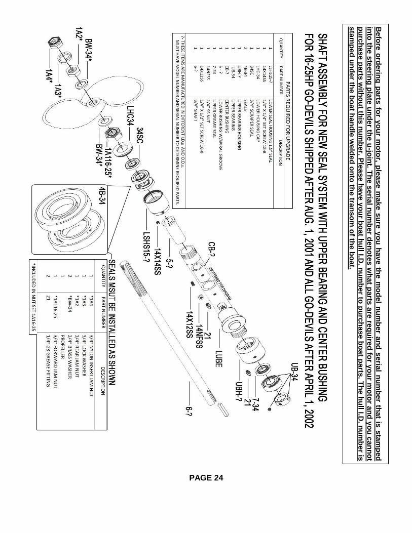
Be
fore
ord
erin
g p
arts
for y
ou
r mo
tor, p
lea
se m
ak
e s
ure
yo
u h
av
e th
e m
od
el n
um
be
r an
d s
eria
l nu
mb
er th
at is
sta
mp
ed
into
the s
tee
ring
pla
te u
nd
er th
e u
-join
t. Th
e s
eria
l nu
mb
er d
en
ote
s w
hat p
arts
are
req
uire
d fo
r yo
ur m
oto
r an
d y
ou
can
no
t
pu
rch
as
e p
arts
with
ou
t this
nu
mb
er. P
leas
e h
av
e y
ou
r bo
at h
ull I.D
. nu
mb
er to
pu
rch
ase
bo
at p
arts
. Th
e h
ull I.D
. nu
mb
er is
sta
mp
ed
un
der th
e b
oa
t han
dle
we
lde
d o
nto
the tra
nso
m o
f the b
oa
t.
PAGE 24
Be
fore
ord
erin
g p
arts
for y
ou
r mo
tor, p
lea
se m
ak
e s
ure
yo
u h
av
e th
e m
od
el n
um
be
r an
d s
eria
l nu
mb
er th
at is
sta
mp
ed
into
the s
tee
ring
pla
te u
nd
er th
e u
-join
t. Th
e s
eria
l nu
mb
er d
en
ote
s w
hat p
arts
are
req
uire
d fo
r yo
ur m
oto
r an
d y
ou
can
no
t
pu
rch
as
e p
arts
with
ou
t this
nu
mb
er. P
leas
e h
av
e y
ou
r bo
at h
ull I.D
. nu
mb
er to
pu
rch
ase
bo
at p
arts
. Th
e h
ull I.D
. nu
mb
er is
sta
mp
ed
un
der th
e b
oa
t han
dle
we
lde
d o
nto
the tra
nso
m o
f the b
oa
t.

PAGE 25
Be
fore
ord
erin
g p
arts
for y
ou
r mo
tor, p
lea
se m
ak
e s
ure
yo
u h
av
e th
e m
od
el n
um
be
r an
d s
eria
l nu
mb
er th
at is
sta
mp
ed
into
the s
tee
ring
pla
te u
nd
er th
e u
-join
t. Th
e s
eria
l nu
mb
er d
en
ote
s w
hat p
arts
are
req
uire
d fo
r yo
ur m
oto
r an
d y
ou
can
no
t
pu
rch
as
e p
arts
with
ou
t this
nu
mb
er. P
leas
e h
av
e y
ou
r bo
at h
ull I.D
. nu
mb
er to
pu
rch
ase
bo
at p
arts
. Th
e h
ull I.D
. nu
mb
er is
sta
mp
ed
un
der th
e b
oa
t han
dle
we
lde
d o
nto
the tra
nso
m o
f the b
oa
t.

NEW SEAL SYSTEMS RETRO-FIT INSTRUCTIONS to install on units sold before June 2001
TOOLS NEEDED
18” Pipe Wrench ½” Drill 1-1/16” Socket or Combination Wrench 1-1/8” Socket or Combination Wrench Pair of Channel Lock Pliers 4 to 5 Lb Hammer 5/16” Drill Bit, 13/64” Drill Bit Center Punch 1/8” Pipe Plug ¼” 28 TPI Tap with Handle 1/8” Allen Wrench ¾” Reamer or ¾” Drill Bit with ½” Shank 36” Reamer Extension with ½” Shank Metal File, Emery Cloth 1” Cold Chisel Blue Loctite RTV Silicone
1. Remove prop, nut set and lower seal assembly. 2. Remove set screws in end yoke on shaft side only. 3. Remove shaft from unit (refer to PAGES 13 and 14). 4. Remove lower bushing (refer to PAGE 16). 5. Unscrew upper seal assembly and knock out upper bushing with old shaft or refer to PAGE 16. 6. Clean all of the old grease out of the housing by pushing paper towels through it several times. 7. Plug the lubricator hole with a 1/8” pipe plug or install a lubricator fitting if unit is not equipped with one. Then install the plug in the lubricator fitting. 8. Measure 34” from the bottom of the tube and center punch a mark the same angle that the grease fitting is located. 9. Drill center punch mark with 13/64” drill bit and tap the hole with a ¼” 28 tap and blow out any drill chips in the tube. 10. Slide in center bushing halfway past the tapped hole and drill a counter-sink a hole 1/16” deep with the 13/64” bit. Do not drill through the bushing. 11. Install the ¼” stainless steel set screw securely into the tube to hold the bushing in place and install the nut to lock it in place. Use blue Loctite on both to keep these parts from coming loose. 12. Install new bottom bushing and ream (refer to PAGE 16). 13. Use a reamer extension and ream the center bushing. Continued on next page.
PAGE 26
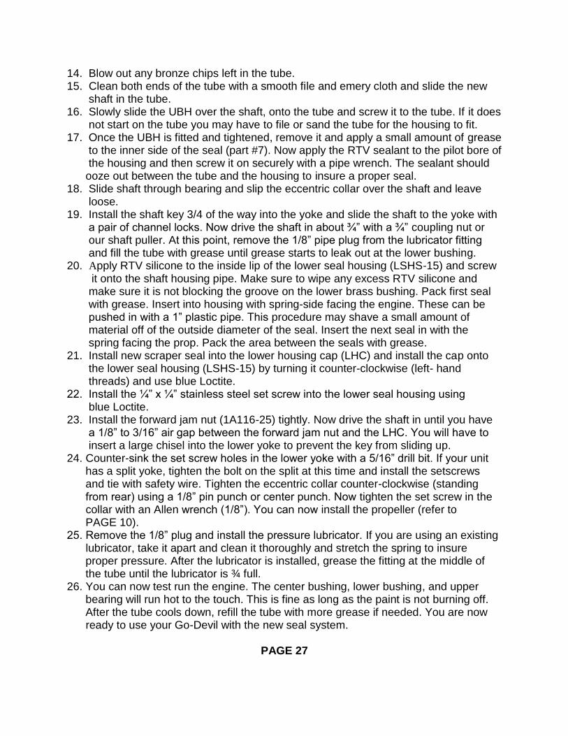
14. Blow out any bronze chips left in the tube. 15. Clean both ends of the tube with a smooth file and emery cloth and slide the new shaft in the tube. 16. Slowly slide the UBH over the shaft, onto the tube and screw it to the tube. If it does not start on the tube you may have to file or sand the tube for the housing to fit. 17. Once the UBH is fitted and tightened, remove it and apply a small amount of grease to the inner side of the seal (part #7). Now apply the RTV sealant to the pilot bore of the housing and then screw it on securely with a pipe wrench. The sealant should ooze out between the tube and the housing to insure a proper seal. 18. Slide shaft through bearing and slip the eccentric collar over the shaft and leave loose. 19. Install the shaft key 3/4 of the way into the yoke and slide the shaft to thefyoke with a pair of channel locks. Now drive the shaft in about ¾” with a ¾” coupling nut or our shaft puller. At this point, remove the 1/8” pipe plug from the lubricator fitting and fill the tube with grease until grease starts to leak out at the lower bushing. 20. Apply RTV silicone to the inside lip of the lower seal housing (LSHS-15) and screw
it onto the shaft housing pipe. Make sure to wipe any excess RTV silicone and make sure it is not blocking the groove on the lower brass bushing. Pack first seal with grease. Insert into housing with spring-side facing the engine. These can be pushed in with a 1” plastic pipe. This procedure may shave a small amount of material off of the outside diameter of the seal. Insert the next seal in with the spring facing the prop. Pack the area between the seals with grease. 21. Install new scraper seal into the lower housing cap (LHC) and install the cap ontoff the lower seal housing (LSHS-15) by turning it counter-clockwise (left- hand threads) and use blue Loctite. 22. Install the ¼” x ¼” stainless steel set screw into the lower seal housing using fffffffblue Loctite. 23. Install the forward jam nut (1A116-25) tightly. Now drive the shaft in until you have a a 1/8” to 3/16” air gap between the forward jam nut and the LHC. You will have to insert a large chisel into the lower yoke to prevent the key from sliding up. 24. Counter-sink the set screw holes in the lower yoke with a 5/16” drill bit. If your unit has a split yoke, tighten the bolt on the split at this time and install the setscrews and tie with safety wire. Tighten the eccentric collar counter-clockwise (standing from rear) using a 1/8” pin punch or center punch. Now tighten the set screw in the collar with an Allen wrench (1/8”). You can now install the propeller (refer to PAGE 10). 25. Remove the 1/8” plug and install the pressure lubricator. If you are using an existing lubricator, take it apart and clean it thoroughly and stretch the spring to insure proper pressure. After the lubricator is installed, grease the fitting at the middle of the tube until the lubricator is ¾ full. 26. You can now test run the engine. The center bushing, lower bushing, andfupper bearing will run hot to the touch. This is fine as long as the paint is not burning off. After the tube cools down, refill the tube with more grease if needed. You are now ready to use your Go-Devil with the new seal system.
PAGE 27

HANDLE INSTALLATION
Standard Handle
STANDARD HANDLE INSTALLATION
1. Remove the nylon lock nuts on the bottom of the engine plate.
2. Install the standard handle by mounting it under the engine plate and securing it with the four nylon lock nuts.
3. Attach the throttle cable on the engine as shown in the photograph for your engine. (see PAGE 29)
PAGE 28

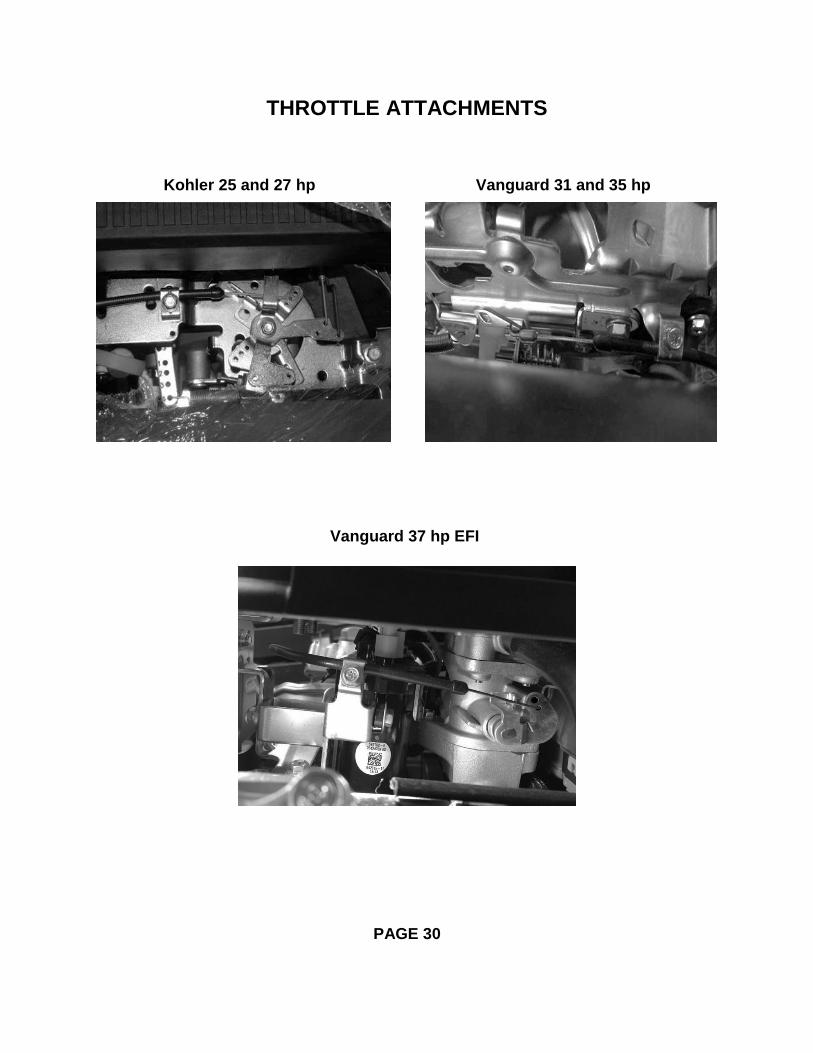
THROTTLE ATTACHMENTS
CONTINUED ON NEXT PAGE
PAGE 29
Vanguard 6.5hp
Honda 9 hp
Vanguard 16,18,20, and 23 hp Honda 20 and 22 hp
Vanguard 6.5 hp
THROTTLE ATTACHMENTS
PAGE 30
Kohler 25 and 27 hp Vanguard 31 and 35 hp
Vanguard 37 hp EFI

Warranty This warranty replaces any warranties before April 1, 2016
Go-Devil Manufacturers of Louisiana, Inc. will repair or replace any
components, on the Go-Devil drive unit that we manufacture at no charge for a
period of two years that are defective in materials or workmanship. Transportation
charges on parts submitted for repair or replacement under this warranty must be
borne by the owner of the unit. This warranty does not cover normal wear, abuse,
neglect, or failure due to the elements of nature, such as salt water corrosion. Wear
on shaft and/or bushing due to the lack of lubrication will not be covered by this
warranty! See your Service Manual for the proper lubrication instructions.
Engines on our products have a three year warranty that is applicable as long
as the original owner owns the unit.
Engine warranty can be handled through any small engine dealer in your
area that is an authorized warranty service dealer for the brand of engine that you
have on your unit. Go-Devil Manufacturers of Louisiana, Inc. is authorized to
warranty all the engines that we sell on our products.