Operation and Maintenance Manualresources.kohler.com/power/kohler/industrial/pdf/...if spare parts...
108
Operation and Maintenance Manual Translation of the original instructions Diesel engine KD45V20 From serial number 2016 18 0001 EN 33521030001_3_1 07-2017
Transcript of Operation and Maintenance Manualresources.kohler.com/power/kohler/industrial/pdf/...if spare parts...
Operation and Maintenance ManualTranslation of the original instructions
Diesel engine
KD45V20From serial number 2016 18 0001
EN 33521030001_3_1
07-2017
Preface Operation and Maintenance Manual
Preface
Only for the United States of America:
This Operating and Maintenance Manual has been written for the operator andmaintenance personnel of the Diesel engine.
It contains descriptions of the:– Technical data– Safety regulations– Handling and operation– Maintenance
Anyone involved in working with or on the Diesel engine must read and follow theinstructions in the Operating and Maintenance Manual carefully both before thefirst commissioning and at regular intervals.
Work with the diesel engine includes:– Handling– Servicing, including maintenance, inspection.
The Operating Manual facilitates the operator's familiarization with the dieselengine and prevents faults through incorrect operation.
2© 2017 by Kohler Co. All rights reserved.
KD45V20 33521030001_3_1 en 2017-08-01

Operation and Maintenance Manual Preface
Kohler Co. will not allow any warranty claims that arise due to incorrect operation,insufficient maintenance, use of unapproved operating fluids or non-compliancewith safety regulations.
Kohler Co. will annul any obligations entered into by Kohler Co. and/or theirdealers such as warranty assurances, service agreements etc. without prior noticeif spare parts other than original Kohler parts or parts purchased from Kohler Co.are used for maintenance and repairs.
In extreme conditions, more frequent maintenance than scheduled in theinspection plan can be required.
Changes, conditions, copyright
This document is protected by copyright. The copyright is held by:– Kohler Co.
Subject to changes in the interests of technical progress.
Proprietary notice ISO 16016: “The reproduction, distribution and utilization of thisdocument as well as the communication of its contents to others without expressauthorization is prohibited. Offenders will be held liable for the payment ofdamages. All rights reserved in the event of the grant of a patent, utility model ordesign.”
List of changes
Version from serial number Comments Date
33521030001_1_1 2016 16 0001 First version December 2016
33521030001_2_1 2016 16 0001 Various changes April 2017
33521030001_3_1 2016 16 0001 Change of maintenanceschedule
August 2017
KD45V20 33521030001_3_1 en 2017-08-01© 2017 by Kohler Co. All rights reserved.
3
Preface Operation and Maintenance Manual
4© 2017 by Kohler Co. All rights reserved.
KD45V20 33521030001_3_1 en 2017-08-01
Contents
Service Assistance 9
1 Product description 11
1.1 Technical description 11
1.1.1 Design overview 11
1.1.2 Overview of sensors 13
1.1.3 Explanation of the type designation 14
1.2 Technical data 17
1.2.1 Diesel engine 17
1.2.2 Cylinder head 17
1.2.3 Coolant thermostat 18
1.2.4 Battery charging alternator 18
1.2.5 Starter 18
1.2.6 Flywheel housing 18
2 Safety 19
2.1 Identification of the warnings 19
2.2 Target audience 19
2.2.1 International standard classification of occupations 20
2.2.2 Occupational references 20
2.2.3 Unauthorized personnel 21
2.3 Intended use 21
2.4 Foreseeable misuse 22
2.5 General safety instructions 22
2.6 Preventing personal injuries 23
2.6.1 Bruises 23
2.6.2 Burns and scalding 23
2.6.3 Fires and explosions 24
2.6.4 Poisoning 24
2.6.5 High-pressure injection (liquids at high pressure can squirt out) 24
KD45V20 33521030001_3_1 en 2017-08-01© 2017 by Kohler Co. All rights reserved.
5

Contents Operation and Maintenance Manual
2.6.6 Electrical energy 25
2.6.7 Danger due to noise 25
2.7 Personal protective equipment 25
2.8 Operating areas and maintenance areas 26
2.8.1 Safety instructions 26
2.8.2 Operating areas 27
2.8.3 Maintenance areas 27
2.8.4 Secure and release the diesel engine against accidental starting 28
2.8.5 Emergency stop 29
2.8.6 Signage 29
2.9 Prevent material damages 30
3 Handling, operation 31
3.1 Start-up procedure 31
3.1.1 Filling the operating fluids 31
3.1.2 Starting the engine 31
4 Operating faults 33
4.1 Errors – Cause – Remedy 33
5 Operating fluids and maintenance 39
5.1 Fill quantities 39
5.1.1 Lubricants and operating materials 39
5.2 Lubricants and operating materials 40
5.2.1 Diesel fuels 40
5.2.2 Engine oils 41
5.2.3 Coolant 43
5.3 Maintenance 45
5.3.1 Maintenance schedule 45
5.3.2 Daily, weekly and monthly maintenance work 46
5.4 Maintenance schedule — ESP Fuel optimized 47
5.4.1 ESP Fuel optimized — Service level 1 47
5.4.2 ESP Fuel optimized — Service level 2 48
5.5 Maintenance schedule — ESP Emission optimized 49
5.5.1 ESP Emission optimized — Service level 1 49
6© 2017 by Kohler Co. All rights reserved.
KD45V20 33521030001_3_1 en 2017-08-01
Operation and Maintenance Manual Contents
5.5.2 ESP Emission optimized — Service level 2 50
5.6 Maintenance schedule — ESP 50Hz emission optimized top power 51
5.6.1 ESP 50Hz emission optimized top power — Service level 1 51
5.6.2 ESP 50Hz emission optimized top power — Service level 2 52
5.7 Maintenance schedule — PRP Fuel optimized 53
5.7.1 PRP Fuel optimized — Service level 1 53
5.7.2 PRP Fuel optimized — Service level 2 54
5.8 Maintenance schedule — PRP Emission optimized 55
5.8.1 PRP Emission optimized — Service level 1 55
5.8.2 PRP Emission optimized — Service level 2 56
5.9 Maintenance schedule — PRP 50Hz emission optimized top power 57
5.9.1 PRP 50Hz emission optimized top power — Service level 1 57
5.9.2 PRP 50Hz emission optimized top power — Service level 2 58
5.10 Maintenance schedule — COP Fuel optimized 59
5.10.1 COP Fuel optimized — Service level 1 59
5.10.2 COP Fuel optimized — Service level 2 60
5.11 Maintenance schedule — COP Emission optimized 61
5.11.1 COP Emission optimized — Service level 1 61
5.11.2 COP Emission optimized — Service level 2 62
5.12 Special tools for maintenance activities 63
5.13 Preparatory maintenance activities 64
5.14 Daily, weekly and monthly maintenance work 65
5.14.1 Perform visual inspection (leaks, damage, loose components). 65
5.14.2 Checking the engine oil level 67
5.14.3 Check coolant level 69
5.14.4 Check the ventilation holes on the water pump. 70
5.14.5 Check/drain water trap on the primary fuel filter 70
5.15 Maintenance activities 72
5.15.1 Take oil sample and perform oil analysis 72
5.15.2 Replace diesel engine oil and oil filter 72
5.15.3 Replace the oil separator filter insert of the crankcase breather 75
5.15.4 Replace main fuel filter 78
5.15.5 Replace the primary fuel filter 80
5.15.6 Take coolant sample and perform coolant analysis. 80
5.15.7 Change air filter main element 81
KD45V20 33521030001_3_1 en 2017-08-01© 2017 by Kohler Co. All rights reserved.
7
Contents Operation and Maintenance Manual
5.15.8 Check state of fan drive belt drive and replace if necessary 81
5.15.9 Check and change the V-ribbed belt for the battery charging alternator 84
6 Transport and storage 87
6.1 Fastening during transport 88
6.2 Wooden transport stand 90
6.3 Steel transport stand 91
6.4 Suspension device 92
6.5 Storage 94
6.6.1 Storage for up to 6 months 94
6.7.1 Storage for over 6 and up to 24 months 94
7.1 Standard torques 95
7.1.1 Standard torques for screw connections 95
7.1.2 Standard torques for screw plugs and hollow screws 96
7.1.3 Standard torques for flange joints 97
7.1.5 Metric flange joints, series L (light) for aluminum 100
7.1.6 Standard torques for cutting ring flange joints 101
7.1.7 Standard torques for Triple Lok® flange joints 101
7.1.8 Standard torques for VSTI screw plugs 102
7.2 Special tool 103
7.3 Terms used (glossary) 104
Index 105
8© 2017 by Kohler Co. All rights reserved.
KD45V20 33521030001_3_1 en 2017-08-01
Service Assistance
Please contact your nearest Kohler Power Systems distributor or dealer forprofessional advice on the generator set power requirements and conscientiousservice.
For Kohler generating sets:
Consult the Yellow Pages under the heading Generators-Electric.– Visit the web site of Kohler Power Systems at KOHLERPower.com.– Pay attention to the labels and decals on your Kohler product or review the
appropriate literature or documents included with the product.– In the USA and Canada, call toll-free 1-800-544-2444.– Outside the USA and Canada, call the nearest regional office.
Headquarters in Europe, the Middle East and Africa (“EMEA”) India, Bangladesh, Sri Lanka
Kohler Power Systems Netherlands B.V. India Regional Office
Kristallaan 1 Bangalore, India
4761 ZC Zevenbergen Phone: (91) 80 3366208
Netherlands (91) 80 3366231
Phone: (31) 168 331630 Fax: (91) 80 3315972
Fax: (31) 168 331631
Japan, Korea
Asia Pacific North Asia Regional Office
Power Systems Asia Pacific Regional Office Tokyo, Japan
Singapore, Republic of Singapore Phone: (813) 3440-4515
Phone: (65) 6264-6422 Fax: (813) 3440-2727
Fax: (65) 6264-6455
China
North China Regional Office, Beijing
Phone: (86) 10 6518 7950
(86) 10 6518 7951
(86) 10 6518 7952
Fax: (86) 10 6518 7955
East China Regional Office, Shanghai
Phone: (86) 21 6288 0500
Fax: (86) 21 6288 0550
Tab. 1
To order special tools, please refer to the cross reference list in the annex.
KD45V20 33521030001_3_1 en 2017-08-01© 2017 by Kohler Co. All rights reserved.
9

Operation and Maintenance Manual
For KOHLER-SDMO power generating units:
– Visit the web site of KOHLER-SDMO at www.kohlersdmo.com.– Pay attention to the labels and stickers on your KOHLER-SDMO product or
check the corresponding literature or documents included with the product'sscope of delivery.
– Call the nearest regional office.
SALES OFFICE FRANCE SOUTHWEST BRANCH OFFICES
WEST SDMO TOULOUSE SOUTH AFRICA
SDMO BREST TEL.: +33 (0) 5 61 24 75 75 SDMO SOUTH AFRICA
TEL.: +33 (0) 2 98 41 13 48 FAX: +33 (0) 5 61 24 75 79 TEL.: +27 (0) 8 32 33 55 61
FAX: +33 (0) 2 98 41 13 57SUBSIDIARIES
FAX: +33 (0) 1 72 27 61 51
MID-WEST GERMANY ALGERIA
SDMO CHOLET SDMO GMBH SDMO ALGIERS
TEL.: +33 (0) 2 41 75 96 70 TEL.: +49 (0) 63 32 97 15 00 TEL.: +213 (0) 21 68 12 12
FAX: +33 (0) 2 41 75 96 71 FAX: +49 (0) 63 32 97 15 11 FAX: +213 (0) 21 68 14 14
PARIS/NORTH & NORMANDY LATIN AMERICA & CARRIBEAN DUBAI
SDMO ARRAS TEL.: +1 (305) 863 0012 SDMO MIDDLE EAST
TEL.: +33 (0) 3 21 73 38 26 FAX: +1 (954) 432 8330 TEL.: +971 4 458 70 20
FAX: +33 (0) 3 21 73 14 59
BELGIUM
FAX: +971 4 458 69 85
SDMO GENNEVILLIERS
TEL.: +33 (0) 1 41 88 38 00 SDMO NV/SA EGYPT
FAX: +33 (0) 1 41 88 38 37 TEL.: +32 36 46 04 15 SDMO KAIRO
EAST FAX: +32 36 46 06 25 TEL./FAX: +20 (2) 22 67 12 78
BRAZIL KENYASDMO METZ
TEL.: +33 (0) 3 87 37 88 50 KOHLER MAQUIGERAL SDMO NAIROBI
FAX: +33 (0) 3 87 37 88 59 TEL.: +55 (11) 37 89 60 00 TEL./FAX: +25 (47) 07 60 54 00
SOUTHEAST SPAIN RUSSIA
SDMO AIX-EN-PROVENCE SDMO INDUSTRIES IBERICA SDMO MOSCOW
TEL.: +33 (0) 4 42 52 51 60 TEL.: +34 (9) 35 86 34 00 TEL.:/FAX: +7 495 665 16 98
FAX: +33 (0) 4 42 52 51 61 FAX: +34 (9) 35 80 31 36
TOGOSDMO VALENCE
UNITED KINGDOMTEL.: +33 (0) 4 75 81 31 00 SDMO WEST AFRICA
FAX: +33 (0) 4 75 81 31 10 SDMO ENERGY LTD. TEL.: +228 22 22 65 65
TEL.: +44 (0) 16 06 83 81 20
TURKEYFAX: +44 (0) 16 06 83 78 63
To order special tools, please refer to the cross reference list SDMO ISTANBUL
in the annex. TEL.: +90 53 07 35 09 10
Tab. 2
10© 2017 by Kohler Co. All rights reserved.
KD45V20 33521030001_3_1 en 2017-08-01
1 Product description
1.1 Technical description
1.1.1 Design overview
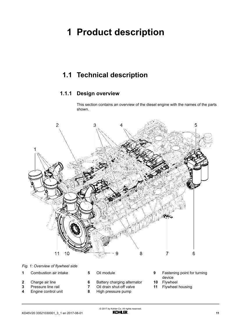
This section contains an overview of the diesel engine with the names of the partsshown.
Fig. 1: Overview of flywheel side
1 Combustion air intake 5 Oil module 9 Fastening point for turningdevice
2 Charge air line 6 Battery charging alternator 10 Flywheel3 Pressure line rail 7 Oil drain shut-off valve 11 Flywheel housing4 Engine control unit 8 High pressure pump
KD45V20 33521030001_3_1 en 2017-08-01© 2017 by Kohler Co. All rights reserved.
11
Product description Operation and Maintenance ManualTechnical description
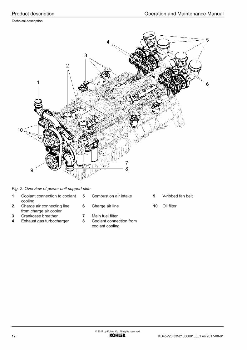
Fig. 2: Overview of power unit support side
1 Coolant connection to coolantcooling
5 Combustion air intake 9 V-ribbed fan belt
2 Charge air connecting linefrom charge air cooler
6 Charge air line 10 Oil filter
3 Crankcase breather 7 Main fuel filter4 Exhaust gas turbocharger 8 Coolant connection from
coolant cooling
12© 2017 by Kohler Co. All rights reserved.
KD45V20 33521030001_3_1 en 2017-08-01

Operation and Maintenance Manual Product descriptionTechnical description
1.1.2 Overview of sensors
Fig. 3: Overview of sensors
1 Rotational speed sensor 4 Rotational speed sensor 7 Rotational speed sensor2 Service switch 5 Temperature sensor3 Temperature sensor 6 Pressure sensor
KD45V20 33521030001_3_1 en 2017-08-01© 2017 by Kohler Co. All rights reserved.
13
Product description Operation and Maintenance ManualTechnical description
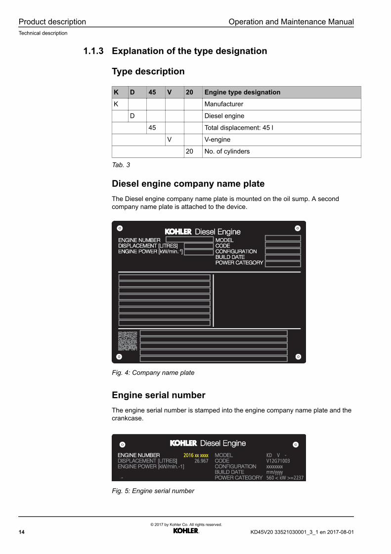
1.1.3 Explanation of the type designation
Type description
K D 45 V 20 Engine type designation
K Manufacturer
D Diesel engine
45 Total displacement: 45 l
V V-engine
20 No. of cylinders
Tab. 3
Diesel engine company name plateThe Diesel engine company name plate is mounted on the oil sump. A secondcompany name plate is attached to the device.
Fig. 4: Company name plate
Engine serial numberThe engine serial number is stamped into the engine company name plate and thecrankcase.
Fig. 5: Engine serial number
14© 2017 by Kohler Co. All rights reserved.
KD45V20 33521030001_3_1 en 2017-08-01

Operation and Maintenance Manual Product descriptionTechnical description
2016 18 0001 Engine serial number
2016 Year of manufacture
18 Engine type code: 18 = KD45V20
0001 Consecutive production number
Tab. 4
Engine control unit nameplate
Fig. 6: Position of the engine control unit nameplate
1 Software nameplate
2 Hardware nameplate
Fig. 7: Example of an engine control unit nameplate
1 Delivery date 5 Engine serial number2 2D code bar 6 Control unit ID number3 Engine type 7 ID number certification4 Control unit description 8 ID number parameter set
KD45V20 33521030001_3_1 en 2017-08-01© 2017 by Kohler Co. All rights reserved.
15
Product description Operation and Maintenance ManualTechnical description
Note The information on the engine control unitnameplate corresponds to the delivery status.Depending on software updates in the field, thisinformation may no longer be up-to-date. The realinformation can be viewed in the device display orread out using the KODIA diagnosis and servicetool.
Tab. 5
16© 2017 by Kohler Co. All rights reserved.
KD45V20 33521030001_3_1 en 2017-08-01

Operation and Maintenance Manual Product descriptionTechnical data
1.2 Technical data
1.2.1 Diesel engine
Description Unit Value
Design V-Diesel engine
No. of cylinders 20
Firing order according to DIN 73021 1–15–4–20–8–17–2–13–6–19–10–16–7–11–3–14–9–18–5–12
Firing order according to ISO 1204 B10–A6–B7–A1–B3–A4–B9–A8–B5–A2–B1–A5–B4–A10–B8–A7–B2–A3–B6–A9
Bore mmin
1355.31
Stroke mmin
1576.18
Displacement lgal
44,94611.8735
Compression ratio 15 :1
Direction of rotation of the Diesel engine (seenfrom flywheel)
Counterclockwise
Power specification as per ISO 3046–1
Rated power See emission controlinformation label
Rated speed See emission controlinformation label
Emission limit stage See engineemissionsnameplate
1.2.2 Cylinder head
Description Unit Value
Inlet valve clearance, cold mmin
0.50.019
Outlet valve clearance, cold mmin
0.60.023
KD45V20 33521030001_3_1 en 2017-08-01© 2017 by Kohler Co. All rights reserved.
17
Product description Operation and Maintenance ManualTechnical data
1.2.3 Coolant thermostat
Description Unit Value
Opening start °C°F
82179
Completely open °C°F
92197
1.2.4 Battery charging alternator
Description Unit Value
Voltage V 28
Current A 140
1.2.5 Starter
Description Unit Value
Voltage V 24
Output per start system kW 7.8
1.2.6 Flywheel housing
Description Unit Value
Connection SAE 0
18© 2017 by Kohler Co. All rights reserved.
KD45V20 33521030001_3_1 en 2017-08-01
2 Safety
2.1 Identification of the warnings
This is a warning sign. It warns you of the risk of possible injury.Follow all of the instructions that accompany this warning sign toavoid any injuries or death.
Tab. 6
This warning sign only appears in conjunction with the signal words:DANGERWARNINGCAUTION
DANGER indicates a hazardous situation which, if notavoided, will result in death or serious injury.
WARNING indicates a hazardous situation which, if notavoided, could result in death or serious injury.
CAUTION indicates a hazardous situation which, if notavoided, could result in minor or moderate injury.
NOTICE indicates a hazardous situation which, if notavoided, could result in material damages.
Tab. 7
Additional markings
Information indicates useful information and tips.
Tab. 8
2.2 Target audience
Level 1 — Basic Maintenance Level 2 — Advanced Maintenance
KD45V20 33521030001_3_1 en 2017-08-01© 2017 by Kohler Co. All rights reserved.
19

Safety Operation and Maintenance ManualTarget audience
Daily checks, inspection and maintenance tasks which canbe carried out in intervals between operation withoutdismantling parts from engine. For example: oil and fuelrefilling
Maintenance tasks involving partial disassembly ofthe engine on site (mid-life service). For example:change of pump, injectors, heads...
By customer or nearest authorized Kohler servicerepresentative.
By customer or nearest authorized Kohler servicerepresentative.
Tab. 9: Service level definition
InformationThe machine's manufacturer is responsible for:
u Checking the personnel's know-how and skills
u Defining the necessary additional, refresher and further qualifications
u Defining the responsibilities and authorizations
u Applying ILO – "C138 – Minimum Age Convention, 1973" with a minimum agefor the work permit of 14 years
u Providing the necessary tools and spare parts
2.2.1 International standard classification of occupations
In accordance with the International Standard Classification of Occupations(ISCO-08) of the International Labor Office (ILO), the following unit groups arelisted as references to define the target audiences, occupations and joint tasks.
2.2.2 Occupational references
The occupations listed perform the following work in accordance with the "Generalsafety instructions" chapter:– the main tasks described in this manual or these instructions– the tasks identified as requirements to prepare the main tasks
For the SL1 maintenance of power generation engines:
Maintenance TechnicianIn relation to ILO – Power Plant or Industrial Machinery Mechanics – unit group7233 / ISCED-97 level 2)
The work on engines, equipment as well as mechanical and electronic equipmentincludes:– Operating the machine and facilities– Performance of scheduled maintenance work– Assembly, installation, assessment, adjustment, testing and maintenance– Location of defects– Recording the repair and maintenance work performed
For the SL2 maintenance of power generation engines:
TechnicianIn relation to ILO – Power Plant or Industrial Machinery Mechanics – unit group7233 / ISCED-97 on at least one level, from 3 to 4)
20© 2017 by Kohler Co. All rights reserved.
KD45V20 33521030001_3_1 en 2017-08-01
Operation and Maintenance Manual SafetyIntended use
The work on engines, equipment as well as mechanical and electronic equipmentincludes:– Operating the machine and facilities– Performance of scheduled maintenance work– Assembly, installation, assessment, adjustment, testing and maintenance– Location of defects– Dismantling and reassembly of the machine as well as the mechanical and
electronic equipment– Ensuring compliance with standards and specifications– Recording the repair and maintenance work performed
2.2.3 Unauthorized personnel
All other persons, including operators, supervisors and trainees, are classified as"unauthorized personnel" for maintenance work.
They are not allowed to service the engine or access the engine compartment orengine cover.
For the operation of power generation engines:
OperatorIn relation to ILO – Power Production Plant Operators – unit group 3131 /ISCED-97 on at least one level, from 2 to 4)
Power production plant operators operate, monitor and maintain switchboards andrelated equipment in electrical control centers which control the production anddistribution of electrical or other power in transmission networks. The workincludes:– Operating, monitoring and inspecting various types of energy-generating power
plants– Operating and controlling power-generating systems and equipment– Controlling start-up and shut-down of power plant equipment– Controlling switching operations, regulating water levels– Communicating with systems operators to regulate and coordinate transmission
loads, frequency and line voltages– Taking readings from charts, meters and gages at established intervals,
troubleshooting and performing corrective action as necessary– Completing and maintaining station records, logs and reports, and
communicating with other plant personnel to assess the equipment operatingstatus
– Cleaning and maintaining equipment such as the battery charging alternator,pumps or compressors in order to prevent defects or damage to theequipment
2.3 Intended use
– Only use the diesel engine for its intended purpose.– Observe the following conditions of the manufacturer:
• Operating conditions• Servicing conditions• Maintenance conditions
KD45V20 33521030001_3_1 en 2017-08-01© 2017 by Kohler Co. All rights reserved.
21
Safety Operation and Maintenance ManualGeneral safety instructions
– Make sure that the following work is only carried out by personnel inaccordance with the target audience definition:• Using the diesel engine.• Servicing the diesel engine.• Maintaining the diesel engine.
Please refer to the “Target audience” chapter for additional information.
– Install all of the guards and protective devices and check their functions beforecommissioning.
– Pay attention to the safety and operating instructions.– Only operate the engine if it is in perfect working order.– Only operate the engine in the speed range specified by the manufacturer.– Bolt the engine to the machine or the corresponding place of use by the fitted
engine mounts and the corresponding tensioning instructions.– If engine mounts are used that have not been fitted by the manufacturer these
have to be approved by the manufacturer.– The engine may only be operated in areas that cannot be accessed by the
general public, in other words the engine may only be operated in conjunctionwith an enclosure or engine compartment cover.
2.4 Foreseeable misuse
The operating and maintenance manual has been drawn up in accordance withapplicable standards and regulations in accordance with state-of-the-arttechnology.
Kohler Co. assumes no liability for:– Failure to observe these instructions– Incorrect use– The employment of personnel who do not satisfy the target audience
requirements.– Alterations and conversions of the diesel engine that have been carried out
without the consent of Kohler Co.– Operating and auxiliary materials that have not been approved by Kohler Co.– The use of non-Kohler spare parts that have not been officially approved by
Kohler Co., including the resulting consequential damages.– Circumvention of and non-compliance with the safety regulations– Failure to observe international and national regulations on occupational health
and safety– Failure to observe international and national regulations on environmental
protection– Unauthorized modifications to the diesel engine– Manipulations to the injection and control system
2.5 General safety instructions
– Requirements to be met by the target audiences for work. See the “Targetaudience” chapter.
– To guarantee assistance after an accident: Make sure a second person is inattendance or that the emergency situation is detected and help provided.
22© 2017 by Kohler Co. All rights reserved.
KD45V20 33521030001_3_1 en 2017-08-01

Operation and Maintenance Manual SafetyPreventing personal injuries
– Before any assembly work, make sure that the personnel are familiar with theoperating and maintenance manual.
– Only allow personnel undergoing training to work on the diesel engine under theconstant supervision of an experienced person
– Check that personnel are conscious of safety and the hazards involved in theirwork on the following conditions:• Observe accident prevention regulations.• Observe generally accepted occupational health and safety regulations.• Observe the operating and maintenance manual.
– Ensure that the personnel wear safe working clothes.– Make sure that the following are not worn:
• Rings• Wristwatches• Ties• Scarves• Open jackets• Loose clothing
– Make sure that the following equipment is available for assembly and that it isclean, complete and undamaged:• Basic tools• Necessary devices• Necessary special tools
– Replace any damaged tools.– Keep the workplace clean and tidy.– Take precautions for any emergency that may occur.– Keep fire extinguishers and first-aid boxes close by.– Keep the emergency telephone numbers close by.– Make sure that the workplace is well lit.– Only perform assembly work if the diesel engine has been secured.– Ensure that the diesel engine is not started by unauthorized persons.
2.6 Preventing personal injuries
2.6.1 Bruises
– Do not lift heavy parts by hand.– Fasten and secure individual parts and larger assemblies carefully with suitable
lifting gear during their replacement.– Use Kohler lifting gear in accordance with its operating manual.– Observe the regulations on the lifting points.– Do not use any load handling devices that are damaged or that have an
inadequate carrying capacity.– Make sure that no persons stand or walk under loads.– If the diesel engine is running, make sure that no objects can come into contact
with rotating parts. Objects may be flung back.
2.6.2 Burns and scalding
The diesel engine is hot at its operating temperature.– Only work on the diesel engine after it has cooled down.– Only touch hot parts with suitable thermal protection gloves.
KD45V20 33521030001_3_1 en 2017-08-01© 2017 by Kohler Co. All rights reserved.
23
Safety Operation and Maintenance ManualPreventing personal injuries
The cooling system is hot and under pressure when the diesel engine is at itsoperating temperature.– Only touch hot parts with suitable thermal protection gloves.– Avoid any contact with parts carrying cooling water.– Check the cooling water level when the end cover of the expansion tank has
cooled down.– Open the cover carefully to release the excess pressure.
The engine oil is hot when the diesel engine is at its operating temperature.– Avoid any skin contact with hot oil or parts carrying oil.
2.6.3 Fires and explosions
– Smoking is prohibited in the direct vicinity of the diesel engine.– Avoid any fires, sparks or open flames when handling fuels and flammable
liquids.– Start the Diesel engine in accordance with the regulations in the operating and
maintenance manual and the assembly manual.– Repair any leaks and replace damaged components.
Fuel and oil that squirts out of leaks can lead to fires.– Wear safety goggles and gloves when working on batteries.– Remove any cleaning rags that are soaked with flammable liquids.– Disconnect the power supply when working on the electrical system.
2.6.4 Poisoning
– Only run the diesel engine in closed rooms if these are sufficiently ventilated.Open doors and windows if a bigger supply of fresh air is needed.
– Never ingest any operating materials.– Do not use drinking bottles for storage purposes.
Escaping liquids can penetrate the skin and cause blood poisoning.– Do not open any pressurized lines or hoses.– Do not disconnect any pressurized lines or hoses.– Protect hands, face and body against escaping liquids when looking for leaks in
pressurized lines and hoses.
2.6.5 High-pressure injection (liquids at high pressure cansquirt out)
When the Diesel engine is running the fuel lines are under a constant fuel pressureof up to 2400 bar. Escaping liquids can penetrate the skin and lead to injuries.
– Only work on the fuel and injection systems when the diesel engine has beenswitched off.Wait at least 20 minutes after turning the Diesel engine off until the pressure inthe injection system has been released before starting work.
– Check the drop in pressure with the KODIA diagnostic program.– Use suitable protective equipment during work on the fuel and injection system
(e.g. safety gloves, safety goggles, etc.).– Do not open any pressurized fuel lines or hoses.– Do not disconnect any pressurized fuel lines or hoses.– Protect hands, face and body against escaping liquids when looking for leaks in
pressurized lines and hoses.
24© 2017 by Kohler Co. All rights reserved.
KD45V20 33521030001_3_1 en 2017-08-01
Operation and Maintenance Manual SafetyPersonal protective equipment
2.6.6 Electrical energy
– The safety zones around the operational Diesel engine may not be accessed bypersons with a heart pacemaker.
– Do not touch any live parts.– Disconnect the power supply before any work on the electrical system.
2.6.7 Danger due to noise
Permanent hearing impediments are possible at noise levels above 84dB(A).Sound level up to 110dB(A) possible!
– Keep all sound-absorbing guards on the equipment closed when the engine isrunning.
– Do not stand near the running engine without hearing protection that is suitablefor the noise level.
– Pay attention to the hearing protection measures in accordance with the dieselengine's operating manual.
The operators and unauthorized personnel may not enter the safety zones whenthe engine is ready for use or running. However, if a technician has to approach anunprotected engine for troubleshooting work he must wear hearing protectionsuitable for the noise level.
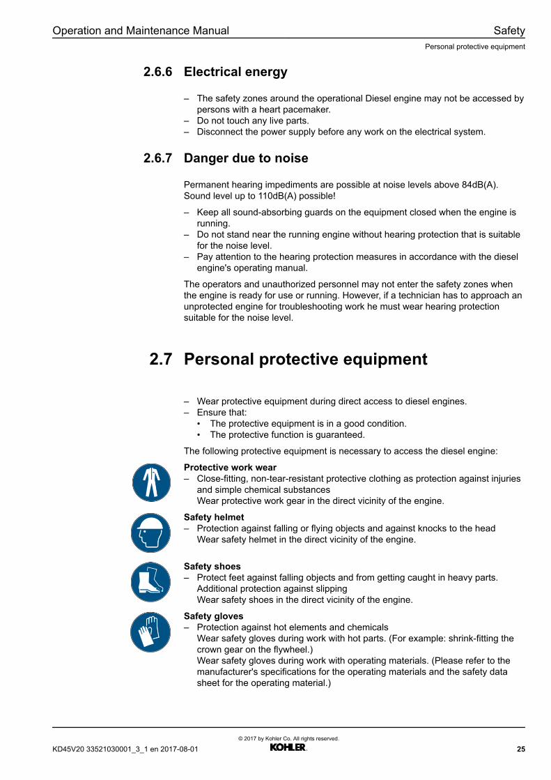
2.7 Personal protective equipment
– Wear protective equipment during direct access to diesel engines.– Ensure that:
• The protective equipment is in a good condition.• The protective function is guaranteed.
The following protective equipment is necessary to access the diesel engine:
Protective work wear– Close-fitting, non-tear-resistant protective clothing as protection against injuries
and simple chemical substancesWear protective work gear in the direct vicinity of the engine.
Safety helmet– Protection against falling or flying objects and against knocks to the head
Wear safety helmet in the direct vicinity of the engine.
Safety shoes– Protect feet against falling objects and from getting caught in heavy parts.
Additional protection against slippingWear safety shoes in the direct vicinity of the engine.
Safety gloves– Protection against hot elements and chemicals
Wear safety gloves during work with hot parts. (For example: shrink-fitting thecrown gear on the flywheel.)Wear safety gloves during work with operating materials. (Please refer to themanufacturer's specifications for the operating materials and the safety datasheet for the operating material.)
KD45V20 33521030001_3_1 en 2017-08-01© 2017 by Kohler Co. All rights reserved.
25

Safety Operation and Maintenance ManualOperating areas and maintenance areas
Hearing protection– Protection against noise
Wear hearing protection near running engines.
Safety goggles– Protection against flying splinters and chemical splashes
Wear safety goggles when handling operating materials. (Please refer to themanufacturer's specifications for the operating materials and the safety datasheet for the operating material.)Wear safety goggles during mechanical operations. (For example when usingcompressed air)
2.8 Operating areas and maintenance areas
2.8.1 Safety instructions
Trapping hazard and flying mechanical parts hazard when the Diesel engine isready for use or running.
Risk of severe injury or death.
– Keep away from engines that are ready for use.– Wear personal protective equipment.– Technicians may enter the safety zone "A" for measuring purposes unless
otherwise indicated by the system manufacturer.
Hot parts when the Diesel engine is ready for use or running.
Risk of burns.
– Keep away from engines that are ready for use.– Wear personal protective equipment.– Leave the engine to cool down sufficiently.
Hazardous voltage. May result in severe injury or death.
Risk of burns from electric shock.
– Only those target audiences authorized as per the relevant definitions mayenter the safety zones during maintenance.
– Disconnect from the electrical power supply.– Wear personal protective equipment.
26© 2017 by Kohler Co. All rights reserved.
KD45V20 33521030001_3_1 en 2017-08-01

Operation and Maintenance Manual SafetyOperating areas and maintenance areas
2.8.2 Operating areas
Fig. 20: Safety zones of engines that are ready for use or running
a Horizontal projection (viewed fromabove)
b Upright projection (viewed fromthe flywheel side)
Access is prohibited to the following areas:
– Safety zone, unit carrier side A– Safety zone next to engine B– Safety zone, flywheel side C– Safety zone, above engine D– Safety zone, below engine E
2.8.3 Maintenance areas
Maintenance areas are the safety zones that have to be accessed for maintenancework and troubleshooting.
WARNINGHot parts during maintenance work.Risk of burns! Can cause severe injury or death.
u Allow the engine to cool down sufficiently.
u Wear personal protective equipment.
KD45V20 33521030001_3_1 en 2017-08-01© 2017 by Kohler Co. All rights reserved.
27

Safety Operation and Maintenance ManualOperating areas and maintenance areas
Fig. 21: Safety zones during maintenance and repairs
a Horizontal projection (viewed fromabove)
b Upright projection (viewed fromthe flywheel side)
Access is allowed to the following areas:
– Safety zone, unit carrier side A– Safety zone next to engine B– Safety zone, flywheel side C– Safety zone, above engine D
Access is prohibited to the following areas:
– Safety zone, below engine E
Access to the maintenance areas must be secured against accidental startingbefore entering the safety zones.
2.8.4 Secure and release the diesel engine againstaccidental starting
Access to the maintenance areas must be secured against accidental startingbefore entering the safety zones.
Procedure:
Secure the diesel engine against any unexpected start-up:– Disconnect diesel fuel supply.– Label cut-off point.– Disconnect electrical power supply and secure against reactivation.– Label cut-off point.
Make the diesel engine ready for operation (release):– The following work has been completed:
• Installation activities• Maintenance activities• Repair activities
– Make sure that all foreign bodies have been removed.– All of the protective devices are installed and are working properly.– Make sure that no external persons stand or walk in the danger zones.
28© 2017 by Kohler Co. All rights reserved.
KD45V20 33521030001_3_1 en 2017-08-01

Operation and Maintenance Manual SafetyOperating areas and maintenance areas
– Remove the label from the fuel supply.– Reconnect the fuel supply.– Remove the label from the electrical power supply.– Establish the electrical power supply.
2.8.5 Emergency stop
An emergency stop is provided for hazardous situations that call for an immediateshutdown of the Diesel engine. The power supply to the Diesel engine isinterrupted immediately. Only the engine control unit still receives current.
Examples of hazardous situations:– Fire– Persons having suffered an electric shock– Diesel engine does not stop– Diesel engine accelerates uncontrollably
Only use the emergency stop in emergencies. Triggering an emergency stop cancause permanent damage to the Diesel engine. The emergency stop may not beused to stop the Diesel engine for operational purposes.
2.8.6 Signage
Information
u The following required signs must be clearly visible and attached in the directvicinity of the safety zones.
u The following required signs must be able to withstand the ambient conditions.The end user must ensure that these are kept visible and legible over the entirelife cycle.
u Additional warnings or adaptations to product standards (ISO 8528-13) arepossible.
ISO 7010 / W012 Warning of dangerous electrical voltage– Only persons who are familiar with the risks of electricity may work within the
identified area.Unauthorized persons may only enter the safety zone after the electrical powersupply has been disconnected.
ISO 7010 / W017 Warning of hot surfaces– The Diesel engine has hot surfaces that are not immediately recognizable as
such.Wait for a sufficient time until the engine has cooled down.Only touch components that may be hot with suitable protective gloves.
ISO 7010 / W025 Warning of entanglement hazard– There are potential trapping hazards on the engine in the area of the V-ribbed
belts and battery charging alternator.Attach a warning sign if traps are not secured through guards (optional).Enter the safety zone only after the Diesel engine has been turned off.Secure the Diesel engine against any unexpected start-up.
ISO 7010 / P007 No access for persons with heart pacemakers or implanteddefibrillators– Possible EMC radiation that may affect heart pacemakers and implanted
defibrillators.People with a heart pacemaker or implanted defibrillator: keep a minimumdistance of 20cm (8 inches) from the operational Diesel engine.
KD45V20 33521030001_3_1 en 2017-08-01© 2017 by Kohler Co. All rights reserved.
29

Safety Operation and Maintenance ManualPrevent material damages
ISO 7010 / M002 Refer to manual– In order to ensure that all residual risks are known by the personnel, the system
documentation must be read and understood.Make sure that all residual risks according to the risk assessment of the systemmanufacturer are reflected in the system documentation.Provide documentation to the personnel according to the "target audience"definitions without restrictions.
2.9 Prevent material damages
– Replace jointing material (e.g. O-rings, seals etc.).– Check reusable removed parts for re-usability; see the relevant information in
the Service Manual and repair instructions.– Replace any removed parts that cannot be re-used.– If no specific torques and tensioning instructions are specified: Screw
connections are to be tightened with the standard torques. Additionalinformation can be found in the "Standard torques" chapter.
– Replace self-locking screw connections.– Clean the diesel engine, connections and screw connections thoroughly of oil,
fuel or care products before assembly.– Use lint-free cleaning rags.– Do not touch electric contacts. The connection is affected by dirt or components
may be destroyed by electrostatic discharges (ESD).– Before cleaning the Diesel engine, cover or tape shut all openings into which
water, steam or detergents must not penetrate due to safety or functionalreasons.
– Remove the covers/seals after cleaning.– Check the fuel lines, Diesel engine oil lines and hydraulic lines for the following
defects:• Leaks• Loose connections• Chafe marks• Damage
– Make sure the electrical power supply is firmly connected when starting.– Make sure the engine is switched off before disconnecting the electrical power
supply.– Use suitable test leads for measurements at plug connections.– Protect the engine control unit against dust and water if no mating plug has
been connected.
30© 2017 by Kohler Co. All rights reserved.
KD45V20 33521030001_3_1 en 2017-08-01

3 Handling, operation
3.1 Start-up procedure
3.1.1 Filling the operating fluids
Fill the following operating fluids before the initial commissioning:
– Diesel engine oilFor suitable lubricating oil for the Diesel engine, see the chapter “Lubricants andoperating fluids”.
– CoolantFor coolant composition, see the chapter “Lubricants and operating fluids”.
– Diesel fuelDiesel fuels must comply with the approved fuel specifications, see the chapter“Lubricants and operating fluids”.
After filling the operating fluids, perform the following work:
u Vent fuel system. Please refer to the generator sets' operating manual.
3.1.2 Starting the engine
Prerequisites:q The oil level is OKq Engine is filled with coolantq Charge air is connectedq Exhaust system is connectedq Electrical power supply is readyq Fuel supply is connected
WARNINGUnexpected movement of the equipment.Causes serious injuries or the death of persons.
u There may be no persons in the safety zones of the diesel engine.
u Bring all of the protective devices into their protective position (housing isclosed), if equipped.
u Secure external parts against unexpected movements. Remove all personsfrom the danger zones.
InformationEngine damage due to inadequate lubrication.
u The oil pressure has to build up immediately after the diesel engine is started(oil-pressure warning lamp goes out).
KD45V20 33521030001_3_1 en 2017-08-01© 2017 by Kohler Co. All rights reserved.
31

Handling, operation Operation and Maintenance ManualStart-up procedure
If all of the safety instructions in the “Safety” chapter have been taken into account:u Switch on the electrical power supply (battery voltage).
Final check
Once the engine has started, carry out the following checks and top up withoperating materials if necessary
u Check the oil level.
u Check the coolant level.
u Perform a visual check for any leaks in the lines.
u Check for KODIA error messages.
u Check for generator sets' error messages.
32© 2017 by Kohler Co. All rights reserved.
KD45V20 33521030001_3_1 en 2017-08-01

4 Operating faults
Please consult the table “Errors – Cause – Remedy” for certain engine problemswith possible causes and corrective action.
Information
Engine errors are shown on the diagnosis and service tool as an error code fordiagnostic purposes.
The following table shows basic logical steps to diagnose the problem:– Familiarize yourself with the engine and related systems.– Investigate the problem carefully.– Correlate the symptoms with your current knowledge of the engine and
systems.– Diagnose the problem, starting with the most obvious assumptions.– Carry out detailed analyses before taking the engine apart.– Identify the causes and thoroughly perform any repair work.
After the repair:– run the engine in accordance with the User Manual.– Check that the causes have been eliminated.– Cancel the fault.
4.1 Errors – Cause – Remedy
Malfunction / error Cause Remedy
The starter does not turn over. The main fuse has blown. Replace the fuse.
The battery connections are loose orcorroded.
Clean and tighten the looseconnections.
The battery voltage is too low. Charge or replace the battery.
The starter’s circuit is faulty or thecontacts are corroded.
Contact KOHLER Co.
The starter is faulty. Contact your nearest authorizedKohler service representative. See"Service Assistance" section.
The starter turns over slowly. The battery voltage is too low. Charge or replace the battery.
The battery connections are loose orcorroded.
Clean and tighten the looseconnections.
The outside temperature is too low. Take appropriate action for Winteroperation.
KD45V20 33521030001_3_1 en 2017-08-01© 2017 by Kohler Co. All rights reserved.
33
Operating faults Operation and Maintenance ManualErrors – Cause – Remedy
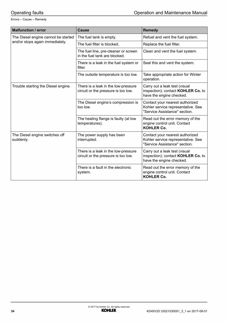
Malfunction / error Cause Remedy
The Diesel engine cannot be startedand/or stops again immediately.
The fuel tank is empty. Refuel and vent the fuel system.
The fuel filter is blocked. Replace the fuel filter.
The fuel line, pre-cleaner or screenin the fuel tank are blocked.
Clean and vent the fuel system.
There is a leak in the fuel system orfilter.
Seal this and vent the system.
The outside temperature is too low. Take appropriate action for Winteroperation.
Trouble starting the Diesel engine. There is a leak in the low-pressurecircuit or the pressure is too low.
Carry out a leak test (visualinspection); contact KOHLER Co. tohave the engine checked.
The Diesel engine’s compression istoo low.
Contact your nearest authorizedKohler service representative. See"Service Assistance" section.
The heating flange is faulty (at lowtemperatures).
Read out the error memory of theengine control unit. ContactKOHLER Co.
The Diesel engine switches offsuddenly.
The power supply has beeninterrupted.
Contact your nearest authorizedKohler service representative. See"Service Assistance" section.
There is a leak in the low-pressurecircuit or the pressure is too low.
Carry out a leak test (visualinspection); contact KOHLER Co. tohave the engine checked.
There is a fault in the electronicsystem.
Read out the error memory of theengine control unit. ContactKOHLER Co.
34© 2017 by Kohler Co. All rights reserved.
KD45V20 33521030001_3_1 en 2017-08-01

Operation and Maintenance Manual Operating faultsErrors – Cause – Remedy
Malfunction / error Cause Remedy
Low output of the Diesel engine(reduced performance).
There is a fault in the fuel system(blockage, leak).
Carry out a visual inspection forleaks, replace the filter. ContactKOHLER Co.
The charge pressure is too low. The terminals are loose, the sealsand hoses are faulty, the air filter isdirty, the turbocharger is faulty.Contact your nearest authorizedKohler service representative. See"Service Assistance" section.
The charge air temperature is toohigh.
The charge air cooler is dirty, thefan’s performance is low, theambient temperature is too high.Contact your nearest authorizedKohler service representative. See"Service Assistance" section.
The coolant temperature is too high. Check the cooler for soiling, checkthe fan and thermostat, check thecoolant level. Contact your nearestauthorized Kohler servicerepresentative. See "ServiceAssistance" section.
The fuel temperature is too high. Contact your nearest authorizedKohler service representative. See"Service Assistance" section.
The injection nozzles are faulty or donot vaporize.
Contact your nearest authorizedKohler service representative. See"Service Assistance" section.
The Diesel engine’s compression istoo low.
Contact your nearest authorizedKohler service representative. See"Service Assistance" section.
There is a fault in the electronicsystem.
Read out the error logs of the enginecontrol unit. Contact your nearestauthorized Kohler servicerepresentative. See "ServiceAssistance" section.
The Diesel engine is too hot(according to the coolanttemperature display).
The coolant level is too low. Fill up with coolant.
The cooler is dirty or calcified. Clean or descale. Contact yournearest authorized Kohler servicerepresentative. See "ServiceAssistance" section.
The thermostat is faulty. Check this and replace if necessary.Contact your nearest authorizedKohler service representative. See"Service Assistance" section.
KD45V20 33521030001_3_1 en 2017-08-01© 2017 by Kohler Co. All rights reserved.
35
Operating faults Operation and Maintenance ManualErrors – Cause – Remedy
Malfunction / error Cause Remedy
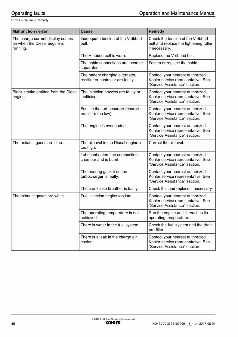
The charge current display comeson when the Diesel engine isrunning.
Inadequate tension of the V-ribbedbelt.
Check the tension of the V-ribbedbelt and replace the tightening rollerif necessary.
The V-ribbed belt is worn. Replace the V-ribbed belt.
The cable connections are loose orseparated.
Fasten or replace the cable.
The battery charging alternator,rectifier or controller are faulty.
Contact your nearest authorizedKohler service representative. See"Service Assistance" section.
Black smoke emitted from the Dieselengine.
The injection nozzles are faulty orinefficient.
Contact your nearest authorizedKohler service representative. See"Service Assistance" section.
Fault in the turbocharger (chargepressure too low).
Contact your nearest authorizedKohler service representative. See"Service Assistance" section.
The engine is overloaded. Contact your nearest authorizedKohler service representative. See"Service Assistance" section.
The exhaust gases are blue. The oil level in the Diesel engine istoo high.
Correct the oil level.
Lubricant enters the combustionchamber and is burnt.
Contact your nearest authorizedKohler service representative. See"Service Assistance" section.
The bearing gasket on theturbocharger is faulty.
Contact your nearest authorizedKohler service representative. See"Service Assistance" section.
The crankcase breather is faulty. Check this and replace if necessary.
The exhaust gases are white. Fuel injection begins too late. Contact your nearest authorizedKohler service representative. See"Service Assistance" section.
The operating temperature is notachieved.
Run the engine until it reaches itsoperating temperature.
There is water in the fuel system. Check the fuel system and the drainpre-filter.
There is a leak in the charge aircooler.
Contact your nearest authorizedKohler service representative. See"Service Assistance" section.
36© 2017 by Kohler Co. All rights reserved.
KD45V20 33521030001_3_1 en 2017-08-01

Operation and Maintenance Manual Operating faultsErrors – Cause – Remedy
Malfunction / error Cause Remedy
The Diesel engine knocks. There is a fault in the combustion. Contact your nearest authorizedKohler service representative. See"Service Assistance" section.
There is an error in the valveclearance.
Adjust the valve clearance.
The injection nozzles are damagedor carbonized.
Contact your nearest authorizedKohler service representative. See"Service Assistance" section.
Bearing damages. Contact your nearest authorizedKohler service representative. See"Service Assistance" section.
The piston rings are worn or faulty,the pistons are eroded.
Contact your nearest authorizedKohler service representative. See"Service Assistance" section.
Abnormal noises from the engine. There are leaks in the intake andexhaust gas lines that cause awhistling noise.
Seal the leaks and replace thegaskets if necessary.
The turbine or compressor wheelrubs against the housing; foreignbodies have penetrated thecompressor or turbine; bearings maybe jammed.
Contact your nearest authorizedKohler service representative. See"Service Assistance" section.
The lubricant pressure is too low. The oil level in the oil sump is toolow.
Fill oil to prescribed mark.
The lubricant is too thin (oil dilutedby Diesel fuel).
Drain the oil and refill with thespecified oil.
The pressure sensor is faulty. Check the oil pressure and replacethe damaged oil pressuretransducer. Contact your nearestauthorized Kohler servicerepresentative. See "ServiceAssistance" section.
The pressure limiting valve does notwork properly or is dirty.
Contact your nearest authorizedKohler service representative. See"Service Assistance" section.
There is lubricant in the coolingsystem.
Leak in the oil cooler or oil coolerplate.
Contact your nearest authorizedKohler service representative. See"Service Assistance" section.
There is coolant in the lubricant. Leaks in the cylinder seals. Contact your nearest authorizedKohler service representative. See"Service Assistance" section.
Leak in the oil cooler or oil coolerplate.
Contact your nearest authorizedKohler service representative. See"Service Assistance" section.
KD45V20 33521030001_3_1 en 2017-08-01© 2017 by Kohler Co. All rights reserved.
37

Operating faults Operation and Maintenance ManualErrors – Cause – Remedy
Malfunction / error Cause Remedy
The charge air temperature is toohigh.
The charge air cooler is dirty. Contact your nearest authorizedKohler service representative. See"Service Assistance" section.
The inlet air temperature is too high. Check the fan, air supply andbreather.
The charge air pressure is too low. The air filter is blocked. Check the air filter’s service display,if equipped.
The charge air cooler is dirty. Contact your nearest authorizedKohler service representative. See"Service Assistance" section.
The turbocharger outlet is faulty. Contact your nearest authorizedKohler service representative. See"Service Assistance" section.
38© 2017 by Kohler Co. All rights reserved.
KD45V20 33521030001_3_1 en 2017-08-01
5 Operating fluids andmaintenance
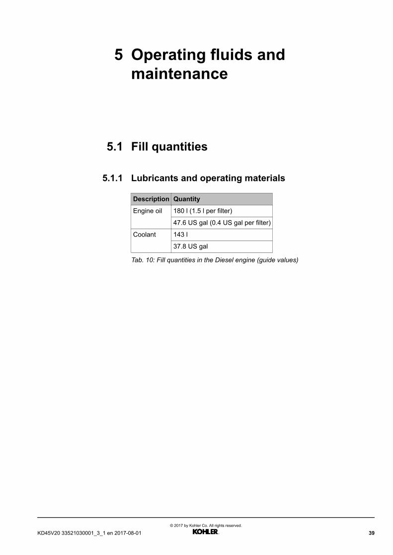
5.1 Fill quantities
5.1.1 Lubricants and operating materials
Description Quantity
Engine oil 180 l (1.5 l per filter)
47.6 US gal (0.4 US gal per filter)
Coolant 143 l
37.8 US gal
Tab. 10: Fill quantities in the Diesel engine (guide values)
KD45V20 33521030001_3_1 en 2017-08-01© 2017 by Kohler Co. All rights reserved.
39
Operating fluids and maintenance Operation and Maintenance ManualLubricants and operating materials
5.2 Lubricants and operating materials
5.2.1 Diesel fuels
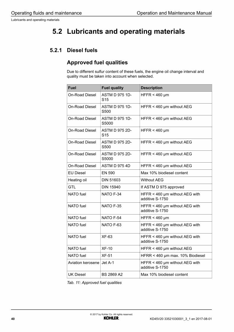
Approved fuel qualitiesDue to different sulfur content of these fuels, the engine oil change interval andquality must be taken into account when selected.
Fuel Fuel quality Description
On-Road Diesel ASTM D 975 1D-S15
HFFR < 460 µm
On-Road Diesel ASTM D 975 1D-S500
HFFR < 460 µm without AEG
On-Road Diesel ASTM D 975 1D-S5000
HFFR < 460 µm without AEG
On-Road Diesel ASTM D 975 2D-S15
HFFR < 460 µm
On-Road Diesel ASTM D 975 2D-S500
HFFR < 460 µm without AEG
On-Road Diesel ASTM D 975 2D-S5000
HFFR < 460 µm without AEG
On-Road Diesel ASTM D 975 4D HFFR < 460 µm without AEG
EU Diesel EN 590 Max 10% biodiesel content
Heating oil DIN 51603 Without AEG
GTL DIN 15940 If ASTM D 975 approved
NATO fuel NATO F-34 HFFR < 460 µm without AEG withadditive S-1750
NATO fuel NATO F-35 HFFR < 460 µm without AEG withadditive S-1750
NATO fuel NATO F-54 HFFR < 460 µm
NATO fuel NATO F-63 HFFR < 460 µm without AEG withadditive S-1750
NATO fuel XF-63 HFFR < 460 µm without AEG withadditive S-1750
NATO fuel XF-10 HFFR < 460 µm without AEG
NATO fuel XF-51 HFRR < 460 µm max. 10% Biodiesel
Aviation kerosene Jet A-1 HFFR < 460 µm without AEG withadditive S-1750
UK Diesel BS 2869 A2 Max 10% biodiesel content
Tab. 11: Approved fuel qualities
40© 2017 by Kohler Co. All rights reserved.
KD45V20 33521030001_3_1 en 2017-08-01

Operation and Maintenance Manual Operating fluids and maintenanceLubricants and operating materials
Minimum requirement for quality
Requirement for the fuel Parameter
Lubrication capability at 60°C (HFRR) 460 µm
Minimum cetane number 45
Purity class according to ISO 4406 20/17/14
Tab. 12: Minimum requirement for Diesel
5.2.2 Engine oils
Performance requirements of the quality categoriesEngine oil additives are not approved, since if they are incorrectly matched with theengine oil they may cause damage.
Lubricantcategory Minimum standards Recommended viscosity
classType of
lubricant
Oilchangefactor
Lubricantcategory 1
ACEA E5-02 or API CH-4 orDHD-1
SAE 10W-40; SAE 10W-30;SAE 15W-40
Mineral oil 1/4
Lubricantcategory 2
ACEA E4 ACEA E7 or APICI-4 Plus or DHD-1 or JASO
DH-1
SAE 10W-40; SAE 10W-30;SAE 5W-30
Synthetic 1
Lubricantcategory 2.1
ACEA E6 or ACEA E9 or APICJ-4 or JASO DH-2
SAE 5W-30; SAE 10W-40;SAE 10W-30
Synthetic 1
Lubricantcategory 3
(standard today)
ACEA E4-12 or both ACEA E4and ACEA E7
SAE 5W-30; SAE 10W-40;SAE 10W-30; SAE 5W-40
Synthetic, VI >160, and Longlife
additive
2
Lubricantcategory 3.1
(standard today)
ACEA E6-12 or both ACEA E6and ACEA E9 or API CK-4
SAE 5W-30; SAE 10W-40;SAE 10W-30; SAE 5W-40
Synthetic, VI >160, and Longlife
additive
2
Tab. 13: Lubricant category
Selecting the engine oilEffect caused by the sulfur content in the fuel
The following table is intended to help select the right engine oil based on the totalbase number (TBN). This measurement value is important for reducing combustiongases that are greatly influenced by the sulfur content in the fuel.
KD45V20 33521030001_3_1 en 2017-08-01© 2017 by Kohler Co. All rights reserved.
41

Operating fluids and maintenance Operation and Maintenance ManualLubricants and operating materials
Fig. 27: The correlation between TBN and sulfur in fuel
1 TBN 3 If TBN <8 mgKOH/g, theengine oil should be replacedas soon as possible.
5 recommended TBN [mgKOH/g]
2 ppm sulfur 4 with TBN [mg KOH/g]
Viscosity class:
The viscosity class has to be selected on the basis of the cold start temperature.The following viscosity classes are permitted for the engines: 5W30, 5W40,10W30, 10W40 and 15W40. The change intervals according to oil category mustbe observed.
Difficulty factorsDifficulty factors can be:– Frequent cold starts– Environmental influences
• Operating temperature• Dust• High humidity• Long standstill times
If there are difficulty factors or difficult usage conditions, the oil change and filterchange must be performed according to the following table.
Engine oil change intervals:The change intervals are defined as follows:
Basic oil change interval * Factor oil category * Factor sulfur content = changeinterval
The basic oil change interval is defined in the maintenance tables.
The factor “oil category”:
Lubricant category Oil change factor (factor 1)
Lubricant category 1 “1/4” => reduces the maintenance intervalby one quarter
42© 2017 by Kohler Co. All rights reserved.
KD45V20 33521030001_3_1 en 2017-08-01

Operation and Maintenance Manual Operating fluids and maintenanceLubricants and operating materials
Lubricant category Oil change factor (factor 1)
Lubricant category 2 and 2.1 1
Lubricant category 3 and 3.1 2 => double the maintenance interval
Tab. 14: Lubricant category table
Factor “sulfur content”:
Sulfur content in % Oil change factor (factor 2)
0 < sulfur content ≤ 0.5 1
0.5 < sulfur content ≤ 1 limited tolubricant category 2 and 3
“1/2” => reduces the maintenance intervalby one half
1 < sulfur content ≤ 1.5 limited tolubricant category 2 and 3
“1/4” => reduces the maintenance intervalby one quarter. The use of sulfur in the
ratio of more than 1% requires anadditional approval of the engine
manufacturer to ensure that all engineoptions, the used lubricant, and the
maintenance schedule are compatible withthis very high sulfur content. Special
lubrication oil must be used => TBN > 12MgKOH/g.
Tab. 15: Sulfur content table
Engine oil analysisThe engine oil can be monitored by means of an engine oil analysis and thechange interval can be adjusted if required.
5.2.3 Coolant
Information
Mixing different anticorrosion antifreeze agents can make the properties of thecoolant worse.u Do not combine different products!
u Silicate-based and non-silicate based coolants must never be mixed; this maydamage the cooling system!
Requirements for waterMake sure that the water used meets the following requirements:– Fully de-ionized water should be used.– Corresponds to the 2006 WHO (World Heath Organization) guideline for
drinking water.
The cooling circuit must remain within the following parameters:– Hardness of water < 12 dH– pH value 6.7 to 9.0– Chloride and sulfate < 100 mg/l
KD45V20 33521030001_3_1 en 2017-08-01© 2017 by Kohler Co. All rights reserved.
43

Operating fluids and maintenance Operation and Maintenance ManualLubricants and operating materials
Requirements of the coolantUse only pre-mixed cooling water of the same kind to avoid problems with thecooling circuit.
An SI-OAT or hybrid technology with ethylene glycol is to be used as coolant, sincethis technology provides the necessary cooling performance and cooling functionfor engines.
Approved products:– BASF GLYSANTIN® G40™ change interval 6 years– BASF GLYSANTIN® G48™ change interval 4 years
The recommended coolant concentration is 40% to 50%.
The coolant can be monitored by means of an coolant analysis and the changeinterval can be adjusted if required. Control parameter for the coolant:
Analysis Standard Unit Value
Visualappearance
Typical color, clear,normal smell, like newcoolant
Nitrate DIN EN 12014 mg/kg <80
Nitrite DIN EN 12014 mg/kg <500
pH value DIN EN ISO10523:2012-04
8.1 — 9.0
Freezing point DIN ISO 3016, ASTM5985
°C -26
Tab. 16: Control parameter
44© 2017 by Kohler Co. All rights reserved.
KD45V20 33521030001_3_1 en 2017-08-01

Operation and Maintenance Manual Operating fluids and maintenanceMaintenance
5.3 Maintenance
5.3.1 Maintenance schedule
Using the maintenance schedule
The intervals during which a component can remain in operation between twomaintenances are in classified as follows:
Interval is the operating period in hours.Limit interval is the maximum operating period in years.
Maintenance work is performed as soon as an interval (operating hours or timeperiod) is reached. The first interval that occurs applies.
Nominal values for the power generating unitPower generating units that satisfy the requirements of ISO 8528-1:2005 are usedto generate current for continuous, peak load and stand-by applications. Theclassifications according to ISO 8528-1:2005 should help improve theunderstanding between manufacturer and customer.
Emergency standby power system (ESP)
The maximum available output that a power generating unit is able to supply if themains current fails or under test conditions up to 200 hours of operation a yearduring variable power sequencing under the given operating conditions, wherebythe maintenance intervals and work are carried out in accordance with themanufacturer’s specifications. The permissible average power output with 24-houroperation should not be more than 85 percent of the nominal ESP value.
Prime power (PRP)
The maximum output that a power generating unit is able to supply continuouslyover an unlimited number of hours a year under the agreed operating conditionswith a variable electric load, whereby the maintenance intervals and work arecarried out in accordance with the manufacturer’s specifications. The permissibleaverage power output with 24-hour operation should not be more than 75 percentof the nominal ESP value.
Continuous operating power (COP)
The maximum output that the power generating unit is able to supply continuouslyover an unlimited number of hours a year under the agreed operating conditionswith a constant electric load, whereby the maintenance intervals and work arecarried out in accordance with the manufacturer’s specifications.
Time between overhauls (TBO)
The average period until Diesel engines have to be overhauled.
KD45V20 33521030001_3_1 en 2017-08-01© 2017 by Kohler Co. All rights reserved.
45
Operating fluids and maintenance Operation and Maintenance ManualMaintenance
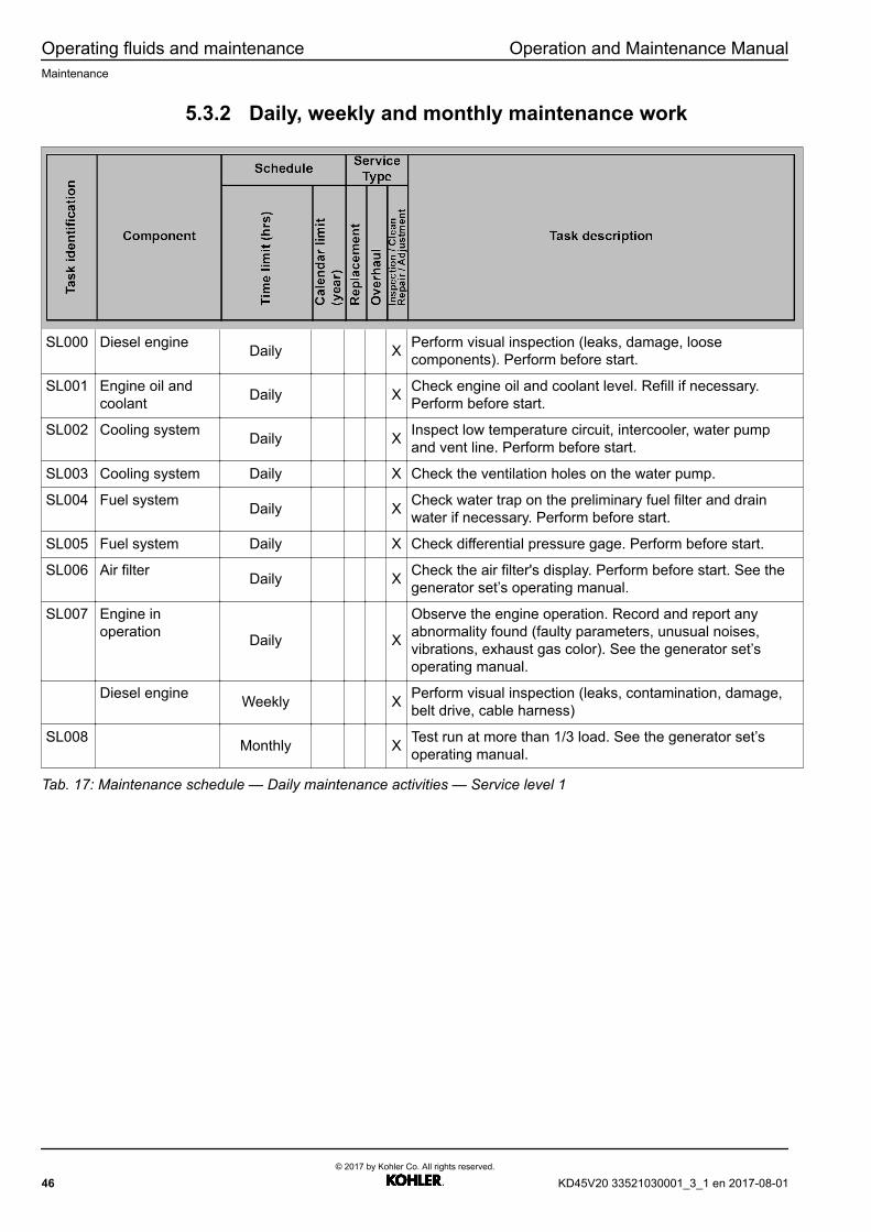
5.3.2 Daily, weekly and monthly maintenance work
SL000 Diesel engine Daily X Perform visual inspection (leaks, damage, loosecomponents). Perform before start.
SL001 Engine oil andcoolant Daily X Check engine oil and coolant level. Refill if necessary.
Perform before start.
SL002 Cooling system Daily X Inspect low temperature circuit, intercooler, water pumpand vent line. Perform before start.
SL003 Cooling system Daily X Check the ventilation holes on the water pump.
SL004 Fuel system Daily X Check water trap on the preliminary fuel filter and drainwater if necessary. Perform before start.
SL005 Fuel system Daily X Check differential pressure gage. Perform before start.
SL006 Air filter Daily X Check the air filter's display. Perform before start. See thegenerator set’s operating manual.
SL007 Engine inoperation Daily X
Observe the engine operation. Record and report anyabnormality found (faulty parameters, unusual noises,vibrations, exhaust gas color). See the generator set’soperating manual.
Diesel engine Weekly X Perform visual inspection (leaks, contamination, damage,belt drive, cable harness)
SL008 Monthly X Test run at more than 1/3 load. See the generator set’soperating manual.
Tab. 17: Maintenance schedule — Daily maintenance activities — Service level 1
46© 2017 by Kohler Co. All rights reserved.
KD45V20 33521030001_3_1 en 2017-08-01

Operation and Maintenance Manual Operating fluids and maintenanceMaintenance schedule — ESP Fuel optimized
5.4 Maintenance schedule — ESP Fueloptimized
5.4.1 ESP Fuel optimized — Service level 1
SL100 Oil analysis 250 1 X Take oil sample and perform oil analysis. Carry out after500 h for category 3 and 2 lubricant.
SL121 Engine oil and oilfilter withlubricant“Category 1”
250 2 X
Replace Diesel engine oil and oil filter insert (at least every2 years). At the latest after one year.
V-ribbed fan belt 500 X Check belt tension.
SL121 Engine oil and oilfilter withlubricant“Category 2”
500 2 X
Replace Diesel engine oil and oil filter insert (at least every2 years). Perform once after 250 hours. At the latest afterone year.
SL105 Main fuel filter 1000 2 X Replace main fuel filter.
SL106 Primary fuel filter 1000 2 X Replace the primary fuel filter.
SL121 Engine oil and oilfilter withlubricant“Category 3”
1000 2 X
Replace Diesel engine oil and oil filter insert (at least every2 years). Perform once after 250 hours. At the latest afterone year.
SL107 Crankcasebreather 2000 2 X Replace oil separator filter insert.
SL118 V-ribbed fan belt 2000 2 X Replace belt.
SL108 Air filter 3000 2 X Replace air filter main element.
SL109 Belt for batterychargingalternator andwater pump
2 X
Check state of belt drive, replace if necessary.
SL120 Coolant analysis 2 X Take coolant sample and perform coolant analysis.
SL116 Coolant 4 X Replace coolant.
Tab. 18: ESP Fuel optimized — Service level 1
KD45V20 33521030001_3_1 en 2017-08-01© 2017 by Kohler Co. All rights reserved.
47

Operating fluids and maintenance Operation and Maintenance ManualMaintenance schedule — ESP Fuel optimized
5.4.2 ESP Fuel optimized — Service level 2
SL204 Cylinder headvalves 1000 2 X Check / set valve clearance.
SL209 High pressurepump 2000 8 X Replace the HP pump.
SL215 Water pump 4000 X Replace water pump
SL225 Viscous damper 4000 X Replace the viscous damper.
SL205 Injection 4500 X Replace fuel lines and injectors.
SL213 Exhaust gasturbocharger 4500 X Replace the exhaust gas turbocharger.
SL219_A
Exhaust gasturbocharger 1 X Replace the exhaust gas turbocharger rubber sleeve.
SL219_B
Lines 4 X X Check and replace lines and hoses if necessary.
Tab. 19: ESP Fuel optimized — Service level 2
48© 2017 by Kohler Co. All rights reserved.
KD45V20 33521030001_3_1 en 2017-08-01
Operation and Maintenance Manual Operating fluids and maintenanceMaintenance schedule — ESP Emission optimized
5.5 Maintenance schedule — ESP Emissionoptimized
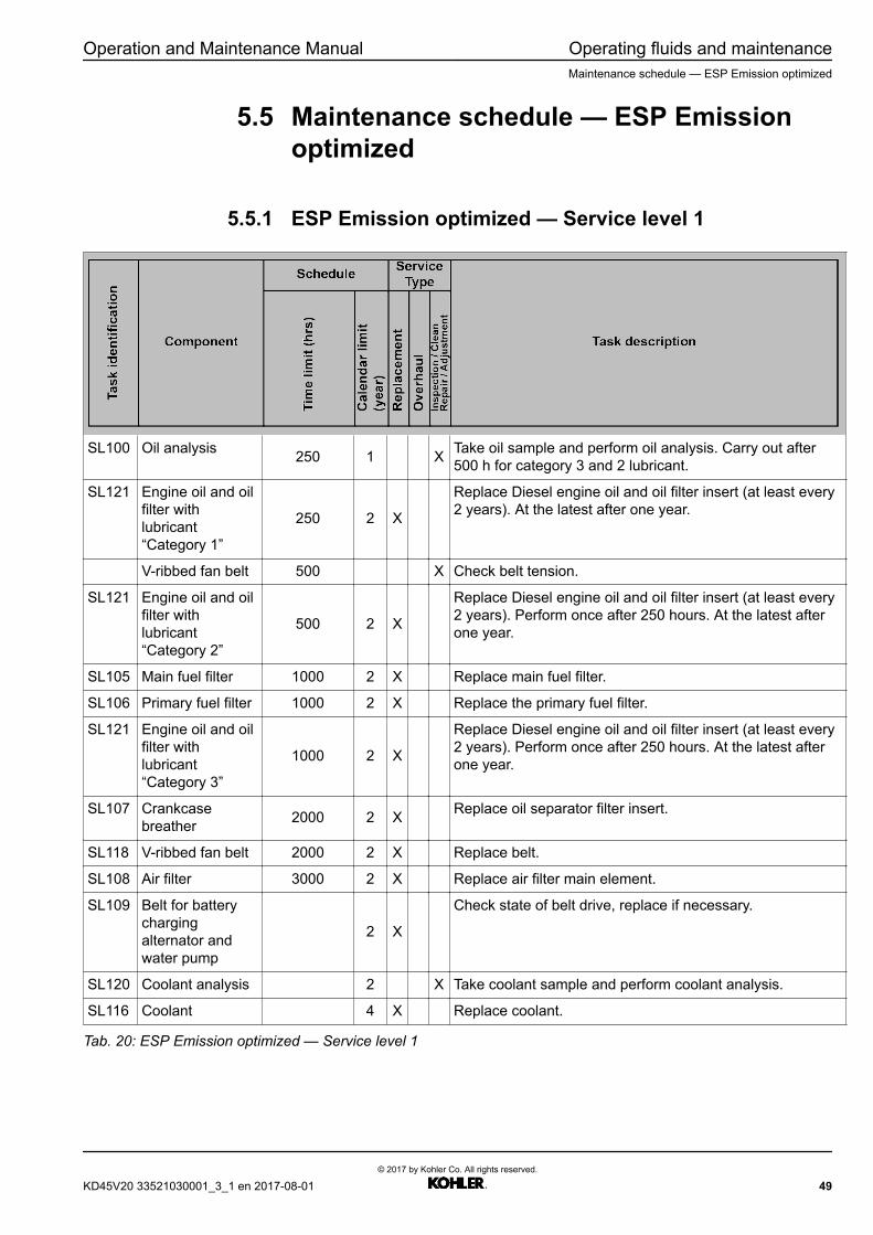
5.5.1 ESP Emission optimized — Service level 1
SL100 Oil analysis 250 1 X Take oil sample and perform oil analysis. Carry out after500 h for category 3 and 2 lubricant.
SL121 Engine oil and oilfilter withlubricant“Category 1”
250 2 X
Replace Diesel engine oil and oil filter insert (at least every2 years). At the latest after one year.
V-ribbed fan belt 500 X Check belt tension.
SL121 Engine oil and oilfilter withlubricant“Category 2”
500 2 X
Replace Diesel engine oil and oil filter insert (at least every2 years). Perform once after 250 hours. At the latest afterone year.
SL105 Main fuel filter 1000 2 X Replace main fuel filter.
SL106 Primary fuel filter 1000 2 X Replace the primary fuel filter.
SL121 Engine oil and oilfilter withlubricant“Category 3”
1000 2 X
Replace Diesel engine oil and oil filter insert (at least every2 years). Perform once after 250 hours. At the latest afterone year.
SL107 Crankcasebreather 2000 2 X Replace oil separator filter insert.
SL118 V-ribbed fan belt 2000 2 X Replace belt.
SL108 Air filter 3000 2 X Replace air filter main element.
SL109 Belt for batterychargingalternator andwater pump
2 X
Check state of belt drive, replace if necessary.
SL120 Coolant analysis 2 X Take coolant sample and perform coolant analysis.
SL116 Coolant 4 X Replace coolant.
Tab. 20: ESP Emission optimized — Service level 1
KD45V20 33521030001_3_1 en 2017-08-01© 2017 by Kohler Co. All rights reserved.
49
Operating fluids and maintenance Operation and Maintenance ManualMaintenance schedule — ESP Emission optimized
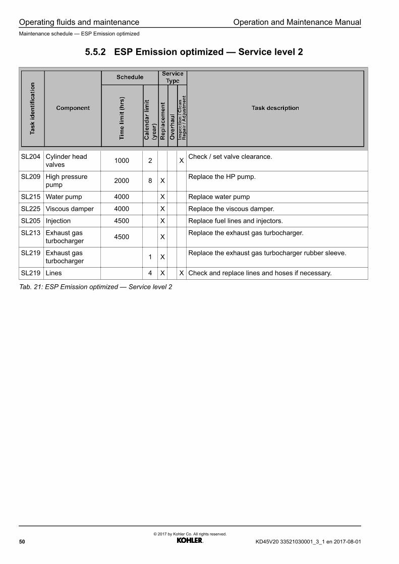
5.5.2 ESP Emission optimized — Service level 2
SL204 Cylinder headvalves 1000 2 X Check / set valve clearance.
SL209 High pressurepump 2000 8 X Replace the HP pump.
SL215 Water pump 4000 X Replace water pump
SL225 Viscous damper 4000 X Replace the viscous damper.
SL205 Injection 4500 X Replace fuel lines and injectors.
SL213 Exhaust gasturbocharger 4500 X Replace the exhaust gas turbocharger.
SL219 Exhaust gasturbocharger 1 X Replace the exhaust gas turbocharger rubber sleeve.
SL219 Lines 4 X X Check and replace lines and hoses if necessary.
Tab. 21: ESP Emission optimized — Service level 2
50© 2017 by Kohler Co. All rights reserved.
KD45V20 33521030001_3_1 en 2017-08-01
Operation and Maintenance Manual Operating fluids and maintenanceMaintenance schedule — ESP 50Hz emission optimized top power
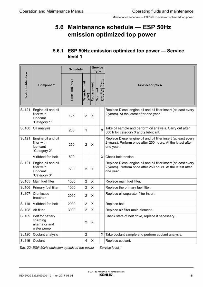
5.6 Maintenance schedule — ESP 50Hzemission optimized top power
5.6.1 ESP 50Hz emission optimized top power — Servicelevel 1
SL121 Engine oil and oilfilter withlubricant“Category 1”
125 2 X
Replace Diesel engine oil and oil filter insert (at least every2 years). At the latest after one year.
SL100 Oil analysis 250 1 X Take oil sample and perform oil analysis. Carry out after500 h for category 3 and 2 lubricant.
SL121 Engine oil and oilfilter withlubricant“Category 2”
250 2 X
Replace Diesel engine oil and oil filter insert (at least every2 years). Perform once after 250 hours. At the latest afterone year.
V-ribbed fan belt 500 X Check belt tension.
SL121 Engine oil and oilfilter withlubricant“Category 3”
500 2 X
Replace Diesel engine oil and oil filter insert (at least every2 years). Perform once after 250 hours. At the latest afterone year.
SL105 Main fuel filter 1000 2 X Replace main fuel filter.
SL106 Primary fuel filter 1000 2 X Replace the primary fuel filter.
SL107 Crankcasebreather 2000 2 X Replace oil separator filter insert.
SL118 V-ribbed fan belt 2000 2 X Replace belt.
SL108 Air filter 3000 2 X Replace air filter main element.
SL109 Belt for batterychargingalternator andwater pump
2 X
Check state of belt drive, replace if necessary.
SL120 Coolant analysis 2 X Take coolant sample and perform coolant analysis.
SL116 Coolant 4 X Replace coolant.
Tab. 22: ESP 50Hz emission optimized top power — Service level 1
KD45V20 33521030001_3_1 en 2017-08-01© 2017 by Kohler Co. All rights reserved.
51

Operating fluids and maintenance Operation and Maintenance ManualMaintenance schedule — ESP 50Hz emission optimized top power
5.6.2 ESP 50Hz emission optimized top power — Servicelevel 2
SL204 Cylinder headvalves 1000 2 X Check / set valve clearance.
SL209 High pressurepump 2000 8 X Replace the HP pump.
SL215 Water pump 4000 X Replace water pump
SL225 Viscous damper 4000 X Replace the viscous damper.
SL205 Injection 4500 X Replace fuel lines and injectors.
SL213 Exhaust gasturbocharger 4500 X Replace the exhaust gas turbocharger.
SL219 Exhaust gasturbocharger 1 X Replace the exhaust gas turbocharger rubber sleeve.
SL219 Lines 4 X X Check and replace lines and hoses if necessary.
Tab. 23: ESP 50Hz emission optimized top power — Service level 2
52© 2017 by Kohler Co. All rights reserved.
KD45V20 33521030001_3_1 en 2017-08-01

Operation and Maintenance Manual Operating fluids and maintenanceMaintenance schedule — PRP Fuel optimized
5.7 Maintenance schedule — PRP Fueloptimized
5.7.1 PRP Fuel optimized — Service level 1
SL100 Oil analysis 250 2 X Take oil sample and perform oil analysis. Carry out after500 h for category 3 and 2 lubricant.
SL121 Engine oil and oilfilter with lube oil“Category 1”
250 2 XReplace Diesel engine oil and oil filter insert (at least every2 years). Perform once after 250 hours. At the latest afterone year.
V-ribbed fan belt 500 X Check belt tension.
SL121 Engine oil and oilfilter with lube oil“Category 2”
500 2 XReplace Diesel engine oil and oil filter insert (at least every2 years). Perform once after 250 hours. At the latest afterone year.
SL105 Main fuel filter 1000 2 X Replace main fuel filter.
SL106 Primary fuel filter 1000 2 Replace the primary fuel filter.
SL121 Engine oil and oilfilter with lube oil“Category 3”
1000 2 XReplace Diesel engine oil and oil filter insert (at least every2 years). Perform once after 250 hours. At the latest afterone year.
SL107 Crankcasebreather 2000 2 X Replace oil separator filter insert.
SL118 V-ribbed fan belt 2000 2 X Replace belt.
SL108 Air filter 3000 2 X Replace air filter main element.
SL109 V-ribbed belt forbattery chargingalternator
4000 2 XCheck state of belt drive, replace if necessary.
SL116 Coolant 6000 4 X Replace coolant.
SL120 Coolant analysis 2 X Take coolant sample and perform coolant analysis.
Tab. 24: PRP Fuel optimized — Service level 1
KD45V20 33521030001_3_1 en 2017-08-01© 2017 by Kohler Co. All rights reserved.
53

Operating fluids and maintenance Operation and Maintenance ManualMaintenance schedule — PRP Fuel optimized
5.7.2 PRP Fuel optimized — Service level 2
SL204 Cylinder headvalves 1000 2 X Check / set valve clearance.
SL205 Injection 7500 X Replace fuel lines and injectors.
SL206 Cylinder 7500 X Clean cumbastion chambers.
SL213 Exhaust gasturbocharger 7500 X Replace the exhaust gas turbocharger.
SL215 Water pump 7500 8 X Replace the water pump.
SL219–A
Exhaust gasturbocharger 7500 X Replace the exhaust gas turbocharger rubber sleeve.
SL219–B
Lines 7500 4 X X Check and replace lines and hoses if necessary.
SL223 Battery chargingalternator 7500 X Replace the battery charging alternator.
SL225 Viscous damper 7500 X Replace the viscous damper.
SL209 High pressurepump 15000 8 X Replace the HP pump.
Tab. 25: PRP Fuel optimized — Service level 2
54© 2017 by Kohler Co. All rights reserved.
KD45V20 33521030001_3_1 en 2017-08-01

Operation and Maintenance Manual Operating fluids and maintenanceMaintenance schedule — PRP Emission optimized
5.8 Maintenance schedule — PRP Emissionoptimized
5.8.1 PRP Emission optimized — Service level 1
SL100 Oil analysis 250 2 X Take oil sample and perform oil analysis. Carry out after500 h for category 3 and 2 lubricant.
SL121 Engine oil and oilfilter with lube oil“Category 1”
250 2 XReplace Diesel engine oil and oil filter insert (at least every2 years). Perform once after 250 hours. At the latest afterone year.
V-ribbed fan belt 500 X Check belt tension.
SL121 Engine oil and oilfilter with lube oil“Category 2”
500 2 XReplace Diesel engine oil and oil filter insert (at least every2 years). Perform once after 250 hours. At the latest afterone year.
SL105 Main fuel filter 1000 2 X Replace main fuel filter.
SL106 Primary fuel filter 1000 2 Replace the primary fuel filter.
SL121 Engine oil and oilfilter with lube oil“Category 3”
1000 2 XReplace Diesel engine oil and oil filter insert (at least every2 years). Perform once after 250 hours. At the latest afterone year.
SL107 Crankcasebreather 2000 2 X Replace oil separator filter insert.
SL118 V-ribbed fan belt 2000 2 X Replace belt.
SL108 Air filter 3000 2 X Replace air filter main element.
SL109 V-ribbed belt forbattery chargingalternator
4000 2 XCheck state of belt drive, replace if necessary.
SL116 Coolant 6000 4 X Replace coolant.
SL120 Coolant analysis 2 X Take coolant sample and perform coolant analysis.
Tab. 26: PRP Emission optimized — Service level 1
KD45V20 33521030001_3_1 en 2017-08-01© 2017 by Kohler Co. All rights reserved.
55
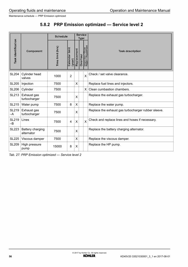
Operating fluids and maintenance Operation and Maintenance ManualMaintenance schedule — PRP Emission optimized
5.8.2 PRP Emission optimized — Service level 2
SL204 Cylinder headvalves 1000 2 X Check / set valve clearance.
SL205 Injection 7500 X Replace fuel lines and injectors.
SL206 Cylinder 7500 X Clean cumbastion chambers.
SL213 Exhaust gasturbocharger 7500 X Replace the exhaust gas turbocharger.
SL215 Water pump 7500 8 X Replace the water pump.
SL219–A
Exhaust gasturbocharger 7500 X Replace the exhaust gas turbocharger rubber sleeve.
SL219–B
Lines 7500 4 X X Check and replace lines and hoses if necessary.
SL223 Battery chargingalternator 7500 X Replace the battery charging alternator.
SL225 Viscous damper 7500 X Replace the viscous damper.
SL209 High pressurepump 15000 8 X Replace the HP pump.
Tab. 27: PRP Emission optimized — Service level 2
56© 2017 by Kohler Co. All rights reserved.
KD45V20 33521030001_3_1 en 2017-08-01

Operation and Maintenance Manual Operating fluids and maintenanceMaintenance schedule — PRP 50Hz emission optimized top power
5.9 Maintenance schedule — PRP 50Hzemission optimized top power
5.9.1 PRP 50Hz emission optimized top power — Servicelevel 1
SL121 Engine oil and oilfilter withlubricant“Category 1”
125 2 X
Replace Diesel engine oil and oil filter insert (at least every2 years). At the latest after one year.
SL100 Oil analysis 250 1 X Take oil sample and perform oil analysis. Carry out after500 h for category 3 and 2 lubricant.
SL121 Engine oil and oilfilter withlubricant“Category 2”
250 2 X
Replace Diesel engine oil and oil filter insert (at least every2 years). Perform once after 250 hours. At the latest afterone year.
V-ribbed fan belt 500 X Check belt tension.
SL121 Engine oil and oilfilter withlubricant“Category 3”
500 2 X
Replace Diesel engine oil and oil filter insert (at least every2 years). Perform once after 250 hours. At the latest afterone year.
SL105 Main fuel filter 1000 2 X Replace main fuel filter.
SL106 Primary fuel filter 1000 2 X Replace the primary fuel filter.
SL107 Crankcasebreather 2000 2 X Replace oil separator filter insert.
SL108 Air filter 3000 2 X Replace air filter main element.
SL109 Belt for batterychargingalternator andwater pump
4000 2 X
Check state of belt drive, replace if necessary.
SL118 V-ribbed fan belt 4000 2 X Replace belt.
SL116 Coolant 6000 4 X Replace coolant.
SL120 Coolant analysis 2 X Take coolant sample and perform coolant analysis.
Tab. 28: PRP 50Hz emission optimized top power — Service level 1
KD45V20 33521030001_3_1 en 2017-08-01© 2017 by Kohler Co. All rights reserved.
57

Operating fluids and maintenance Operation and Maintenance ManualMaintenance schedule — PRP 50Hz emission optimized top power
5.9.2 PRP 50Hz emission optimized top power — Servicelevel 2
SL204 Cylinder headvalves 1000 2 X Check / set valve clearance.
SL205 Injection 7500 X Replace fuel lines and injectors.
SL206 Cylinder 7500 X Clean cumbastion chambers.
SL213 Exhaust gasturbocharger 7500 X Replace the exhaust gas turbocharger.
SL215 Water pump 7500 8 X Replace the water pump.
SL219_A
Exhaust gasturbocharger 7500 X Replace the exhaust gas turbocharger rubber sleeve.
SL219_B
Lines 7500 4 X X Check and replace lines and hoses if necessary.
SL223 Battery chargingalternator 7500 X Replace the battery charging alternator.
SL225 Viscous damper 7500 X Replace the viscous damper.
SL209 High pressurepump 15000 8 X Replace the HP pump.
Tab. 29: PRP 50Hz emission optimized top power — Service level 2
58© 2017 by Kohler Co. All rights reserved.
KD45V20 33521030001_3_1 en 2017-08-01
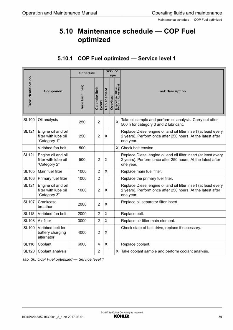
Operation and Maintenance Manual Operating fluids and maintenanceMaintenance schedule — COP Fuel optimized
5.10 Maintenance schedule — COP Fueloptimized
5.10.1 COP Fuel optimized — Service level 1
SL100 Oil analysis 250 2 X Take oil sample and perform oil analysis. Carry out after500 h for category 3 and 2 lubricant.
SL121 Engine oil and oilfilter with lube oil“Category 1”
250 2 XReplace Diesel engine oil and oil filter insert (at least every2 years). Perform once after 250 hours. At the latest afterone year.
V-ribbed fan belt 500 X Check belt tension.
SL121 Engine oil and oilfilter with lube oil“Category 2”
500 2 XReplace Diesel engine oil and oil filter insert (at least every2 years). Perform once after 250 hours. At the latest afterone year.
SL105 Main fuel filter 1000 2 X Replace main fuel filter.
SL106 Primary fuel filter 1000 2 Replace the primary fuel filter.
SL121 Engine oil and oilfilter with lube oil“Category 3”
1000 2 XReplace Diesel engine oil and oil filter insert (at least every2 years). Perform once after 250 hours. At the latest afterone year.
SL107 Crankcasebreather 2000 2 X Replace oil separator filter insert.
SL118 V-ribbed fan belt 2000 2 X Replace belt.
SL108 Air filter 3000 2 X Replace air filter main element.
SL109 V-ribbed belt forbattery chargingalternator
4000 2 XCheck state of belt drive, replace if necessary.
SL116 Coolant 6000 4 X Replace coolant.
SL120 Coolant analysis 2 X Take coolant sample and perform coolant analysis.
Tab. 30: COP Fuel optimized — Service level 1
KD45V20 33521030001_3_1 en 2017-08-01© 2017 by Kohler Co. All rights reserved.
59
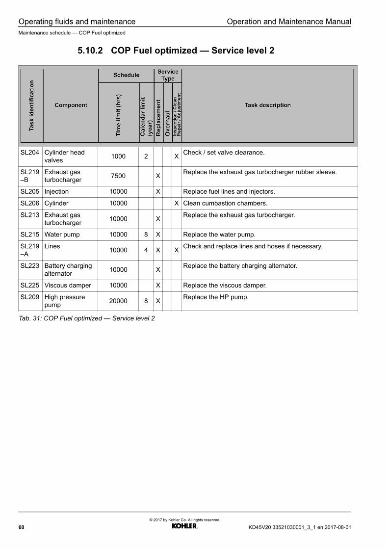
Operating fluids and maintenance Operation and Maintenance ManualMaintenance schedule — COP Fuel optimized
5.10.2 COP Fuel optimized — Service level 2
SL204 Cylinder headvalves 1000 2 X Check / set valve clearance.
SL219–B
Exhaust gasturbocharger 7500 X Replace the exhaust gas turbocharger rubber sleeve.
SL205 Injection 10000 X Replace fuel lines and injectors.
SL206 Cylinder 10000 X Clean cumbastion chambers.
SL213 Exhaust gasturbocharger 10000 X Replace the exhaust gas turbocharger.
SL215 Water pump 10000 8 X Replace the water pump.
SL219–A
Lines 10000 4 X X Check and replace lines and hoses if necessary.
SL223 Battery chargingalternator 10000 X Replace the battery charging alternator.
SL225 Viscous damper 10000 X Replace the viscous damper.
SL209 High pressurepump 20000 8 X Replace the HP pump.
Tab. 31: COP Fuel optimized — Service level 2
60© 2017 by Kohler Co. All rights reserved.
KD45V20 33521030001_3_1 en 2017-08-01

Operation and Maintenance Manual Operating fluids and maintenanceMaintenance schedule — COP Emission optimized
5.11 Maintenance schedule — COP Emissionoptimized
5.11.1 COP Emission optimized — Service level 1
SL100 Oil analysis 250 2 X Take oil sample and perform oil analysis. Carry out after500 h for category 3 and 2 lubricant.
SL121 Engine oil and oilfilter with lube oil“Category 1”
250 2 XReplace Diesel engine oil and oil filter insert (at least every2 years). Perform once after 250 hours. At the latest afterone year.
V-ribbed fan belt 500 X Check belt tension.
SL121 Engine oil and oilfilter with lube oil“Category 2”
500 2 XReplace Diesel engine oil and oil filter insert (at least every2 years). Perform once after 250 hours. At the latest afterone year.
SL105 Main fuel filter 1000 2 X Replace main fuel filter.
SL106 Primary fuel filter 1000 2 Replace the primary fuel filter.
SL121 Engine oil and oilfilter with lube oil“Category 3”
1000 2 XReplace Diesel engine oil and oil filter insert (at least every2 years). Perform once after 250 hours. At the latest afterone year.
SL107 Crankcasebreather 2000 2 X Replace oil separator filter insert.
SL118 V-ribbed fan belt 2000 2 X Replace belt.
SL108 Air filter 3000 2 X Replace air filter main element.
SL109 V-ribbed belt forbattery chargingalternator
4000 2 XCheck state of belt drive, replace if necessary.
SL116 Coolant 6000 4 X Replace coolant.
SL120 Coolant analysis 2 X Take coolant sample and perform coolant analysis.
Tab. 32: COP Emission optimized — Service level 1
KD45V20 33521030001_3_1 en 2017-08-01© 2017 by Kohler Co. All rights reserved.
61

Operating fluids and maintenance Operation and Maintenance ManualMaintenance schedule — COP Emission optimized
5.11.2 COP Emission optimized — Service level 2
SL204 Cylinder headvalves 1000 2 X Check / set valve clearance.
SL219–B
Exhaust gasturbocharger 7500 X Replace the exhaust gas turbocharger rubber sleeve.
SL205 Injection 10000 X Replace fuel lines and injectors.
SL206 Cylinder 10000 X Clean cumbastion chambers.
SL213 Exhaust gasturbocharger 10000 X Replace the exhaust gas turbocharger.
SL215 Water pump 10000 8 X Replace the water pump.
SL219–A
Lines 10000 4 X X Check and replace lines and hoses if necessary.
SL223 Battery chargingalternator 10000 X Replace the battery charging alternator.
SL225 Viscous damper 10000 X Replace the viscous damper.
SL209 High pressurepump 20000 8 X Replace the HP pump.
Tab. 33: COP Emission optimized — Service level 2
62© 2017 by Kohler Co. All rights reserved.
KD45V20 33521030001_3_1 en 2017-08-01

Operation and Maintenance Manual Operating fluids and maintenanceSpecial tools for maintenance activities
5.12 Special tools for maintenance activities
Fig. 45: Turning device
ID no. Description
10123791 Turning device
Tab. 34
KD45V20 33521030001_3_1 en 2017-08-01© 2017 by Kohler Co. All rights reserved.
63
Operating fluids and maintenance Operation and Maintenance ManualPreparatory maintenance activities
5.13 Preparatory maintenance activities
Safety precautions for maintenance
The safety regulations must be observed while performing maintenance work! Seethe “Safety” chapter.
Maintenance position
The diesel engine is in the maintenance position when:– The Diesel engine is horizontal.– The Diesel engine is turned off.– The diesel engine has cooled down to the ambient temperature.– Disconnect electrical power supply and secure against reactivation.– Label cut-off point.
64© 2017 by Kohler Co. All rights reserved.
KD45V20 33521030001_3_1 en 2017-08-01

Operation and Maintenance Manual Operating fluids and maintenanceDaily, weekly and monthly maintenance work
5.14 Daily, weekly and monthly maintenancework
Make sure that:q The Diesel engine is in the maintenance position.
5.14.1 Perform visual inspection (leaks, damage, loosecomponents).
Fig. 46
1 Turbocharger 4 Main fuel filter 7 Engine control unit2 High pressure pump
connectors5 Oil module
3 Oil filter 6 Water pump
u Visually check Diesel engine for leaks, ensure that it is not damaged and thatthe fastenings comply with regulations.
u Visually check V-space (area under high pressure pump and lines) for moisture.
KD45V20 33521030001_3_1 en 2017-08-01© 2017 by Kohler Co. All rights reserved.
65

Operating fluids and maintenance Operation and Maintenance ManualDaily, weekly and monthly maintenance work
Fig. 47
8 Vent line 10 Overflow-oil line9 Pressure line 11 Fuel line
u Visually check hoses for leaks, ensure that they are not damaged, installedfriction-free, and that fastening is in compliance with regulations.
66© 2017 by Kohler Co. All rights reserved.
KD45V20 33521030001_3_1 en 2017-08-01

Operation and Maintenance Manual Operating fluids and maintenanceDaily, weekly and monthly maintenance work
Fig. 48: Inspection overview
1 Cable harness 2 V-ribbed belt
u Visually check cable harness 1 for damage, friction-free installation, andregulation-compliant fastening.
u Visually check belt drive 2 for damage, friction-free installation, and regulation-compliant fastening.
5.14.2 Checking the engine oil level
Oil dipstick and oil filler neck are located on the right as seen from the flywheel.
KD45V20 33521030001_3_1 en 2017-08-01© 2017 by Kohler Co. All rights reserved.
67
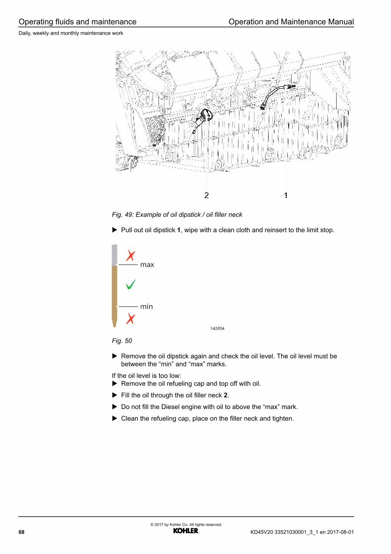
Operating fluids and maintenance Operation and Maintenance ManualDaily, weekly and monthly maintenance work
Fig. 49: Example of oil dipstick / oil filler neck
u Pull out oil dipstick 1, wipe with a clean cloth and reinsert to the limit stop.
Fig. 50
u Remove the oil dipstick again and check the oil level. The oil level must bebetween the “min” and “max” marks.
If the oil level is too low:u Remove the oil refueling cap and top off with oil.
u Fill the oil through the oil filler neck 2.
u Do not fill the Diesel engine with oil to above the “max” mark.
u Clean the refueling cap, place on the filler neck and tighten.
68© 2017 by Kohler Co. All rights reserved.
KD45V20 33521030001_3_1 en 2017-08-01
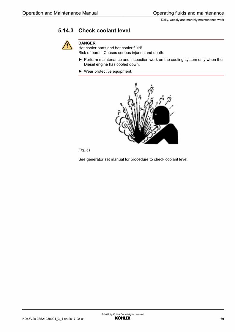
Operation and Maintenance Manual Operating fluids and maintenanceDaily, weekly and monthly maintenance work
5.14.3 Check coolant level
DANGERHot cooler parts and hot cooler fluid!Risk of burns! Causes serious injuries and death.
u Perform maintenance and inspection work on the cooling system only when theDiesel engine has cooled down.
u Wear protective equipment.
Fig. 51
See generator set manual for procedure to check coolant level.
KD45V20 33521030001_3_1 en 2017-08-01© 2017 by Kohler Co. All rights reserved.
69
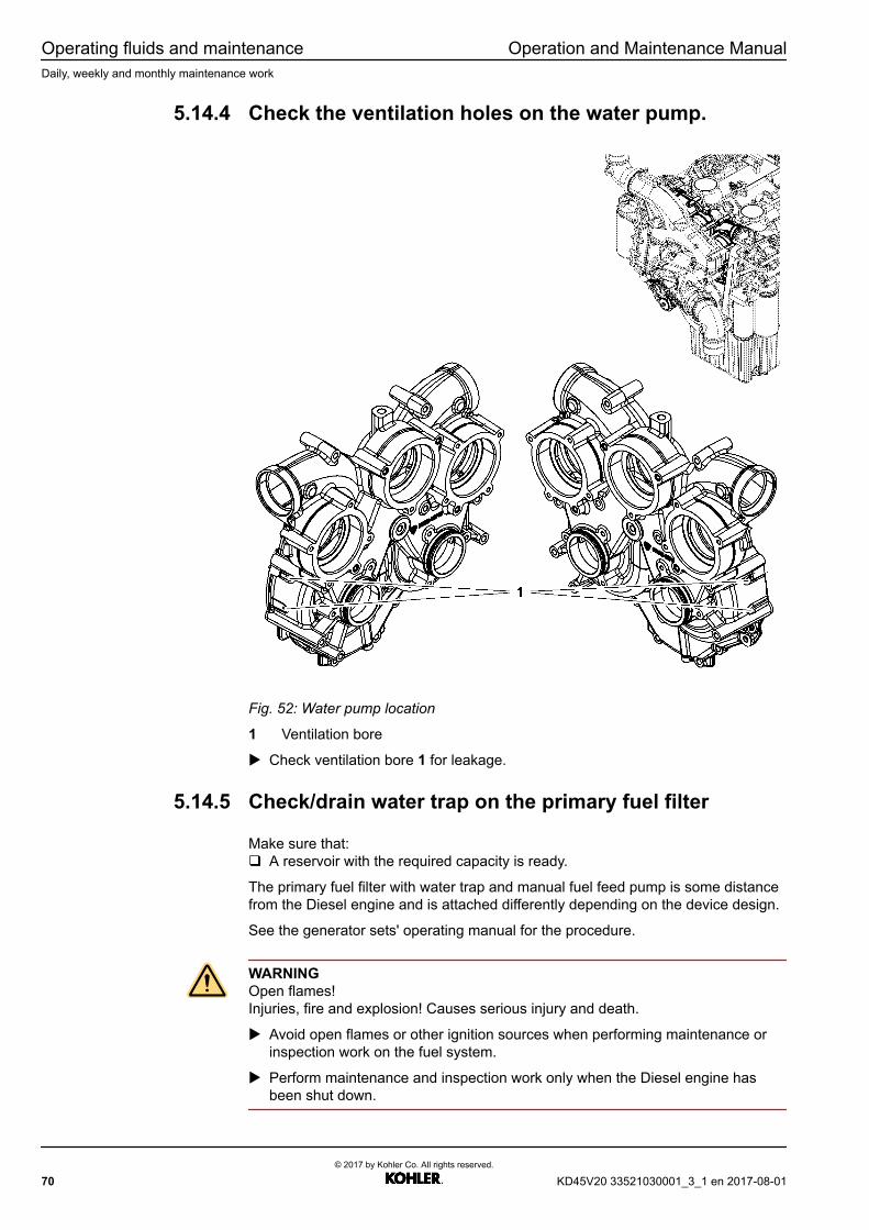
Operating fluids and maintenance Operation and Maintenance ManualDaily, weekly and monthly maintenance work
5.14.4 Check the ventilation holes on the water pump.
Fig. 52: Water pump location
1 Ventilation bore
u Check ventilation bore 1 for leakage.
5.14.5 Check/drain water trap on the primary fuel filter
Make sure that:q A reservoir with the required capacity is ready.
The primary fuel filter with water trap and manual fuel feed pump is some distancefrom the Diesel engine and is attached differently depending on the device design.
See the generator sets' operating manual for the procedure.
WARNINGOpen flames!Injuries, fire and explosion! Causes serious injury and death.
u Avoid open flames or other ignition sources when performing maintenance orinspection work on the fuel system.
u Perform maintenance and inspection work only when the Diesel engine hasbeen shut down.
70© 2017 by Kohler Co. All rights reserved.
KD45V20 33521030001_3_1 en 2017-08-01
Operation and Maintenance Manual Operating fluids and maintenanceDaily, weekly and monthly maintenance work
KD45V20 33521030001_3_1 en 2017-08-01© 2017 by Kohler Co. All rights reserved.
71

Operating fluids and maintenance Operation and Maintenance ManualMaintenance activities
5.15 Maintenance activities
Make sure that:q The Diesel engine is in the maintenance position.
5.15.1 Take oil sample and perform oil analysis
Ensure that:q A reservoir with the required capacity is ready.q A suitable sample bottle is ready.
Fig. 53: Oil removal point
1 Oil removal point
u Refer to the generator set manual for procedure when taking oil sample andperforming oil analysis.
5.15.2 Replace diesel engine oil and oil filter
Make sure that:q The Diesel engine is horizontal.q The Diesel engine is turned off.
72© 2017 by Kohler Co. All rights reserved.
KD45V20 33521030001_3_1 en 2017-08-01
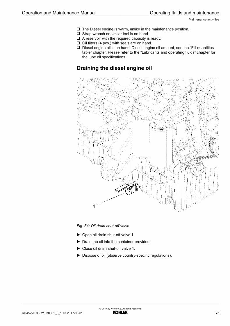
Operation and Maintenance Manual Operating fluids and maintenanceMaintenance activities
q The Diesel engine is warm, unlike in the maintenance position.q Strap wrench or similar tool is on hand.q A reservoir with the required capacity is ready.q Oil filters (4 pcs.) with seals are on hand.q Diesel engine oil is on hand. Diesel engine oil amount, see the “Fill quantities
table” chapter. Please refer to the “Lubricants and operating fluids” chapter forthe lube oil specifications.
Draining the diesel engine oil
Fig. 54: Oil drain shut-off valve
u Open oil drain shut-off valve 1.
u Drain the oil into the container provided.
u Close oil drain shut-off valve 1.
u Dispose of oil (observe country-specific regulations).
KD45V20 33521030001_3_1 en 2017-08-01© 2017 by Kohler Co. All rights reserved.
73
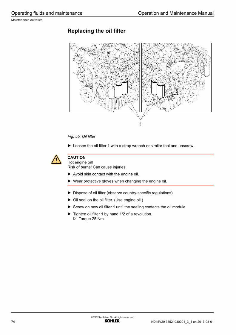
Operating fluids and maintenance Operation and Maintenance ManualMaintenance activities
Replacing the oil filter
Fig. 55: Oil filter
u Loosen the oil filter 1 with a strap wrench or similar tool and unscrew.
CAUTIONHot engine oil!Risk of burns! Can cause injuries.
u Avoid skin contact with the engine oil.
u Wear protective gloves when changing the engine oil.
u Dispose of oil filter (observe country-specific regulations).
u Oil seal on the oil filter. (Use engine oil.)
u Screw on new oil filter 1 until the sealing contacts the oil module.
u Tighten oil filter 1 by hand 1/2 of a revolution.w Torque 25 Nm.
74© 2017 by Kohler Co. All rights reserved.
KD45V20 33521030001_3_1 en 2017-08-01
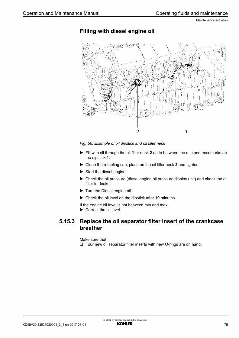
Operation and Maintenance Manual Operating fluids and maintenanceMaintenance activities
Filling with diesel engine oil
Fig. 56: Example of oil dipstick and oil filler neck
u Fill with oil through the oil filler neck 2 up to between the min and max marks onthe dipstick 1.
u Clean the refueling cap, place on the oil filler neck 2 and tighten.
u Start the diesel engine.
u Check the oil pressure (diesel engine oil pressure display unit) and check the oilfilter for leaks.
u Turn the Diesel engine off.
u Check the oil level on the dipstick after 10 minutes.
If the engine oil level is not between min and max:u Correct the oil level.
5.15.3 Replace the oil separator filter insert of the crankcasebreather
Make sure that:q Four new oil separator filter inserts with new O-rings are on hand.
KD45V20 33521030001_3_1 en 2017-08-01© 2017 by Kohler Co. All rights reserved.
75

Operating fluids and maintenance Operation and Maintenance ManualMaintenance activities
Crankcase breather position
Fig. 57: Crankcase breather position
1 Crankcase breather
76© 2017 by Kohler Co. All rights reserved.
KD45V20 33521030001_3_1 en 2017-08-01

Operation and Maintenance Manual Operating fluids and maintenanceMaintenance activities
Remove oil separator filter insert
Fig. 58: Remove filter insert
u Pull off hose clamps 1 and hose from the regulating valve (cover) 2.
u Loosen lever screws 3.
u Remove regulating valve (cover) 2.
u Pull off filter insert 4.
Install oil separator filter insert
Fig. 59: Install filter insert
KD45V20 33521030001_3_1 en 2017-08-01© 2017 by Kohler Co. All rights reserved.
77

Operating fluids and maintenance Operation and Maintenance ManualMaintenance activities
u Lubricate O-ring 6 of the new filter insert 4 with engine oil.
u Insert new filter insert.
u Fit new O-ring 5 on the regulating valve (cover) 2.
u Lubricate O-ring with engine oil.
u Position regulating valve (cover) 2; alignment power unit support side (observeflow direction).
Fig. 60: Filter insert installed
u Fix regulating valve in place with lever screws 3.
u Push on hose and tighten hose clamps.
5.15.4 Replace main fuel filter
Make sure that:q A reservoir with the required capacity is ready.q The main fuel filter is on hand.q Strap wrench or similar tool is on hand.
The main fuel filter is on the left as seen from the flywheel.
WARNINGOpen flames!Injuries, fire and explosion! Can cause injuries or death.
u Avoid open flames or other ignition sources when performing maintenance orinspection work on the fuel system.
u Perform maintenance and inspection work only when the Diesel engine hasbeen shut down.
78© 2017 by Kohler Co. All rights reserved.
KD45V20 33521030001_3_1 en 2017-08-01
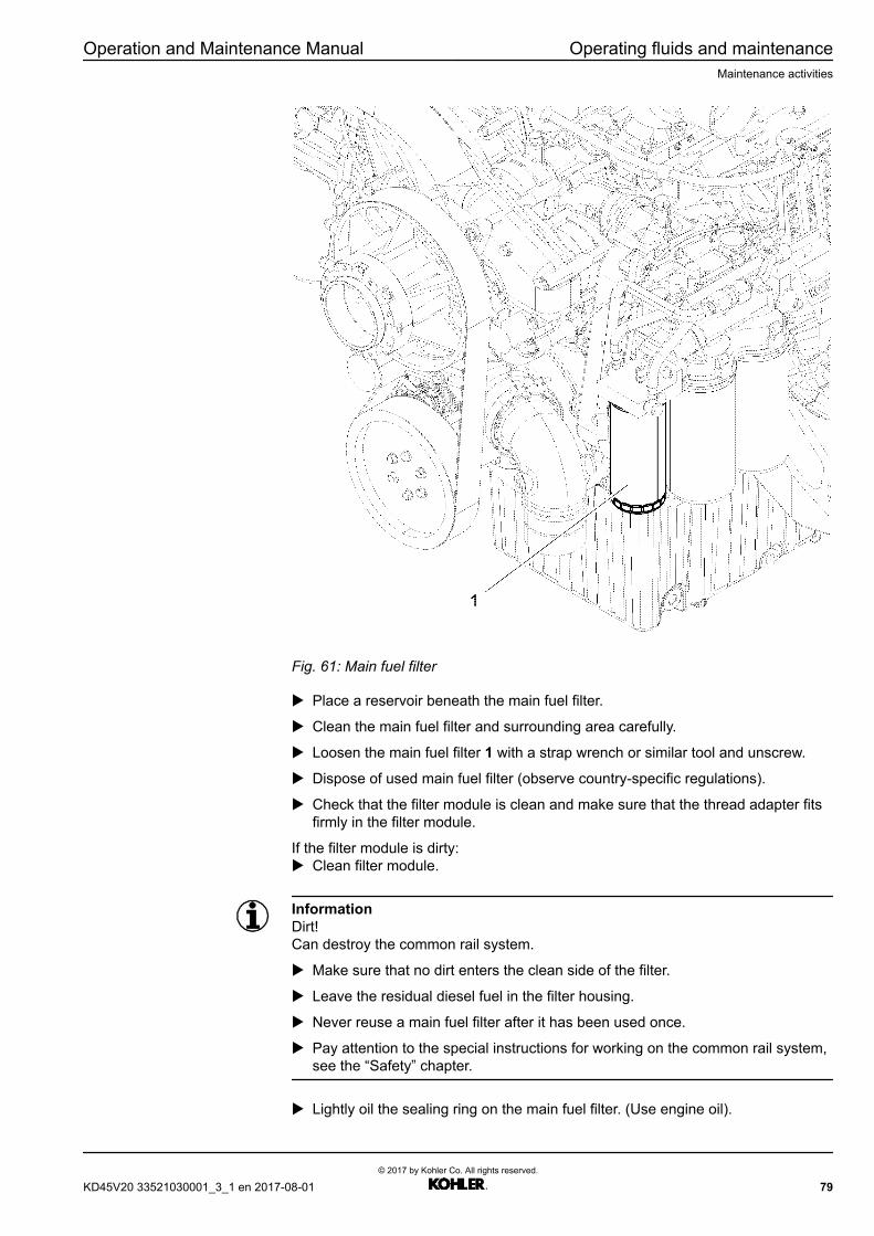
Operation and Maintenance Manual Operating fluids and maintenanceMaintenance activities
Fig. 61: Main fuel filter
u Place a reservoir beneath the main fuel filter.
u Clean the main fuel filter and surrounding area carefully.
u Loosen the main fuel filter 1 with a strap wrench or similar tool and unscrew.
u Dispose of used main fuel filter (observe country-specific regulations).
u Check that the filter module is clean and make sure that the thread adapter fitsfirmly in the filter module.
If the filter module is dirty:u Clean filter module.
InformationDirt!Can destroy the common rail system.
u Make sure that no dirt enters the clean side of the filter.
u Leave the residual diesel fuel in the filter housing.
u Never reuse a main fuel filter after it has been used once.
u Pay attention to the special instructions for working on the common rail system,see the “Safety” chapter.
u Lightly oil the sealing ring on the main fuel filter. (Use engine oil).
KD45V20 33521030001_3_1 en 2017-08-01© 2017 by Kohler Co. All rights reserved.
79
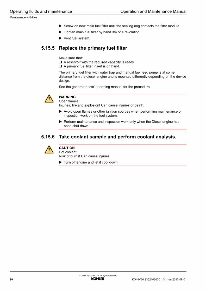
Operating fluids and maintenance Operation and Maintenance ManualMaintenance activities
u Screw on new main fuel filter until the sealing ring contacts the filter module.
u Tighten main fuel filter by hand 3/4 of a revolution.
u Vent fuel system.
5.15.5 Replace the primary fuel filter
Make sure that:q A reservoir with the required capacity is ready.q A primary fuel filter insert is on hand.
The primary fuel filter with water trap and manual fuel feed pump is at somedistance from the diesel engine and is mounted differently depending on the devicedesign.
See the generator sets' operating manual for the procedure.
WARNINGOpen flames!Injuries, fire and explosion! Can cause injuries or death.
u Avoid open flames or other ignition sources when performing maintenance orinspection work on the fuel system.
u Perform maintenance and inspection work only when the Diesel engine hasbeen shut down.
5.15.6 Take coolant sample and perform coolant analysis.
CAUTIONHot coolant!Risk of burns! Can cause injuries.
u Turn off engine and let it cool down.
80© 2017 by Kohler Co. All rights reserved.
KD45V20 33521030001_3_1 en 2017-08-01
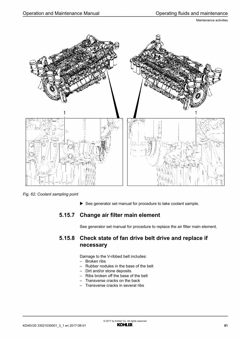
Operation and Maintenance Manual Operating fluids and maintenanceMaintenance activities
Fig. 62: Coolant sampling point
u See generator set manual for procedure to take coolant sample.
5.15.7 Change air filter main element
See generator set manual for procedure to replace the air filter main element.
5.15.8 Check state of fan drive belt drive and replace ifnecessary
Damage to the V-ribbed belt includes:– Broken ribs– Rubber nodules in the base of the belt– Dirt and/or stone deposits– Ribs broken off the base of the belt– Transverse cracks on the back– Transverse cracks in several ribs
KD45V20 33521030001_3_1 en 2017-08-01© 2017 by Kohler Co. All rights reserved.
81

Operating fluids and maintenance Operation and Maintenance ManualMaintenance activities
Fig. 63: Damage to the V-ribbed belt
Checking the V-ribbed belt
WARNINGRotating parts!Risk of injury! Causes serious injuries.
u Turn the Diesel engine off.
u Secure the engine against unexpected starting.
u Check the belt for damage.
u Check that the belt pulleys and tightening roller are in perfect working order andcheck their play (for example, worn out bearings on the tightening roller or treadwear on the belt pulleys).w Replace the damaged parts. Please contact the nearest authorized Kohler
Co. customer service.
Replacing the beltMake sure that:q A new belt is on hand.q A suitable frequency device is on hand.
WARNINGRotating parts!Risk of injury! Causes serious injuries.
u Turn the Diesel engine off.
u Secure the engine against unexpected starting.
82© 2017 by Kohler Co. All rights reserved.
KD45V20 33521030001_3_1 en 2017-08-01
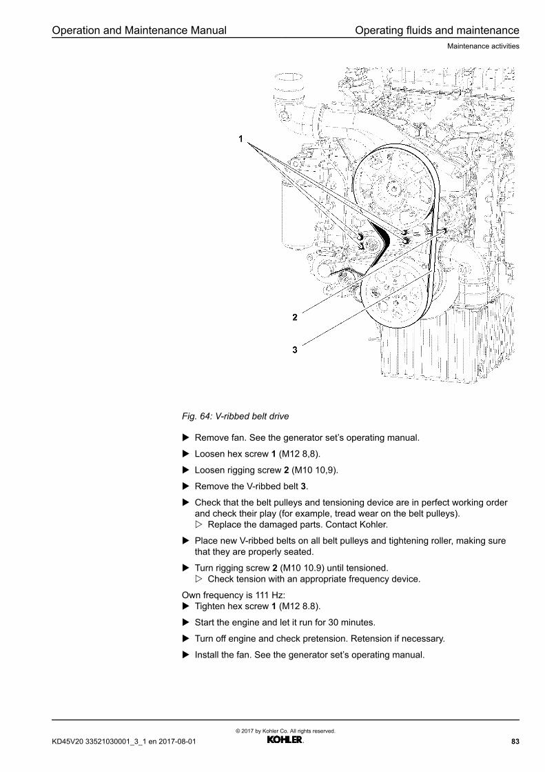
Operation and Maintenance Manual Operating fluids and maintenanceMaintenance activities
Fig. 64: V-ribbed belt drive
u Remove fan. See the generator set’s operating manual.
u Loosen hex screw 1 (M12 8,8).
u Loosen rigging screw 2 (M10 10,9).
u Remove the V-ribbed belt 3.
u Check that the belt pulleys and tensioning device are in perfect working orderand check their play (for example, tread wear on the belt pulleys).w Replace the damaged parts. Contact Kohler.
u Place new V-ribbed belts on all belt pulleys and tightening roller, making surethat they are properly seated.
u Turn rigging screw 2 (M10 10.9) until tensioned.w Check tension with an appropriate frequency device.
Own frequency is 111 Hz:u Tighten hex screw 1 (M12 8.8).
u Start the engine and let it run for 30 minutes.
u Turn off engine and check pretension. Retension if necessary.
u Install the fan. See the generator set’s operating manual.
KD45V20 33521030001_3_1 en 2017-08-01© 2017 by Kohler Co. All rights reserved.
83

Operating fluids and maintenance Operation and Maintenance ManualMaintenance activities
5.15.9 Check and change the V-ribbed belt for the batterycharging alternator
Damage to the V-ribbed belt includes:– Broken ribs– Rubber nodules in the base of the belt– Dirt and/or stone deposits– Ribs broken off the base of the belt– Transverse cracks on the back– Transverse cracks in several ribs
Fig. 65: Damage to the V-ribbed belt
Replacing the beltMake sure that:q A new belt is on hand.
WARNINGRotating parts!Risk of injury! Causes serious injuries.
u Turn the Diesel engine off.
u Secure the engine against unexpected starting.
84© 2017 by Kohler Co. All rights reserved.
KD45V20 33521030001_3_1 en 2017-08-01

Operation and Maintenance Manual Operating fluids and maintenanceMaintenance activities
Fig. 66: V-ribbed belt drive
u Remove fan. See the generator set’s operating manual.
u Remove the V-ribbed belt (fan) 1. (For the procedure, please refer to thechapter “Check state of fan drive belt drive, replace if necessary”.)
KD45V20 33521030001_3_1 en 2017-08-01© 2017 by Kohler Co. All rights reserved.
85
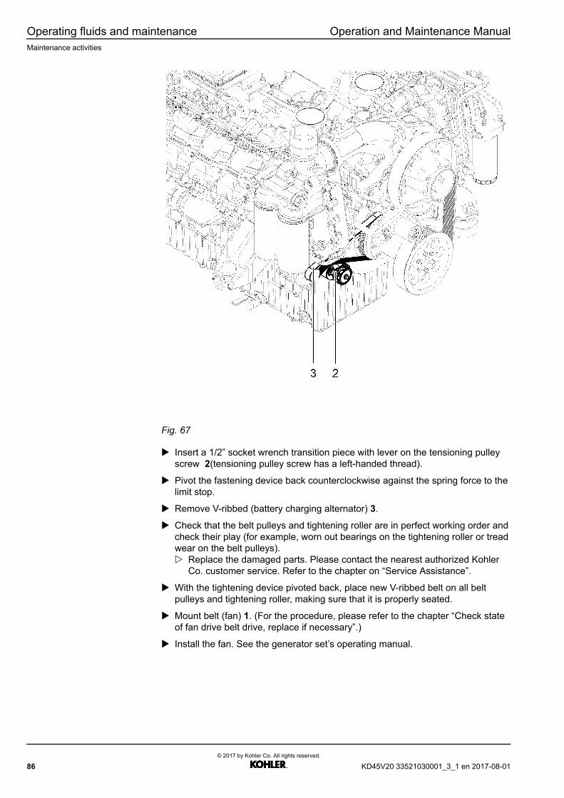
Operating fluids and maintenance Operation and Maintenance ManualMaintenance activities
Fig. 67
u Insert a 1/2” socket wrench transition piece with lever on the tensioning pulleyscrew 2(tensioning pulley screw has a left-handed thread).
u Pivot the fastening device back counterclockwise against the spring force to thelimit stop.
u Remove V-ribbed (battery charging alternator) 3.
u Check that the belt pulleys and tightening roller are in perfect working order andcheck their play (for example, worn out bearings on the tightening roller or treadwear on the belt pulleys).w Replace the damaged parts. Please contact the nearest authorized Kohler
Co. customer service. Refer to the chapter on “Service Assistance”.
u With the tightening device pivoted back, place new V-ribbed belt on all beltpulleys and tightening roller, making sure that it is properly seated.
u Mount belt (fan) 1. (For the procedure, please refer to the chapter “Check stateof fan drive belt drive, replace if necessary”.)
u Install the fan. See the generator set’s operating manual.
86© 2017 by Kohler Co. All rights reserved.
KD45V20 33521030001_3_1 en 2017-08-01
6 Transport and storage
DANGERProtective atmosphere against damage by oxidation inside the protective film.Mortal danger, risk of suffocation! Causes serious injuries or death.
u Remove and store the protective film only in a well-ventilated area.
u The protective film may be stored only in areas that are out of the reach ofchildren.
CAUTIONIncorrect waste disposal.Environmental and health hazard.
u Pay attention to national and international regulations on the disposal of wastesubstances.
u Dispose of all wastes in suitable containers.
u Store wastes in dedicated storage places.
NOTICEIncorrect setting down of the Diesel engine.Engine damage.
u Do not stand the Diesel engine on the oil sump.
u Place the Diesel engine on the appropriate fastening pieces.
NOTICEIncorrect storage.Damage by oxidation.
u Store the Diesel engine only in dry places.
u Do not expose the Diesel engine to great fluctuations in temperature.
u Remove the transport protection film only shortly before installation.
When the Diesel engine is removed:u Cover with a new protective film and observe the climatic conditions for storage.
NOTICEStorage conditions are part of the device manufacturer.
u Comply with the standard ISO 6749-1984 for transportation and storage.
u Please contact the Kohler customer service if anything is unclear.
KD45V20 33521030001_3_1 en 2017-08-01© 2017 by Kohler Co. All rights reserved.
87

Transport and storage Operation and Maintenance ManualFastening during transport
NOTICEThe equipment owner is responsible for compliance with the maximum floor load.
u Check the maximum floor load before setting the Diesel engine down on thefloor.
u The weight data can be found in the technical data sheet.
Information
u Use only preservation media approved by Kohler.
6.1 Fastening during transport
Fig. 68: Example of transport fastening / wood transport stand
DANGERMortal danger due to instability during transportation of the Diesel engine. Theengine can come loose during transportation.Mortal danger! Causes serious injuries or death.
u Transport the Diesel engine only with the transport stand.
u The transport stand used must be in perfect technical condition.
u Secure the transport stand against slipping and toppling over in every direction.
u Pay attention to the center of gravity.
88© 2017 by Kohler Co. All rights reserved.
KD45V20 33521030001_3_1 en 2017-08-01

Operation and Maintenance Manual Transport and storageFastening during transport
DANGERMortal danger due to the Diesel engine falling down/over. Incorrect handling duringloading/unloading of the Diesel engine.Mortal danger! Causes serious injuries or death.
u The Diesel engine may only be loaded/unloaded by suitably trained andauthorized personnel.
u If a crane or forklift truck is used this must be designed for the weight to belifted.
u If a crane is used, please use the hoisting beam.
u There may be no persons within the danger zones of the Diesel engine duringloading and unloading.
u Pay attention to the center of gravity.
KD45V20 33521030001_3_1 en 2017-08-01© 2017 by Kohler Co. All rights reserved.
89
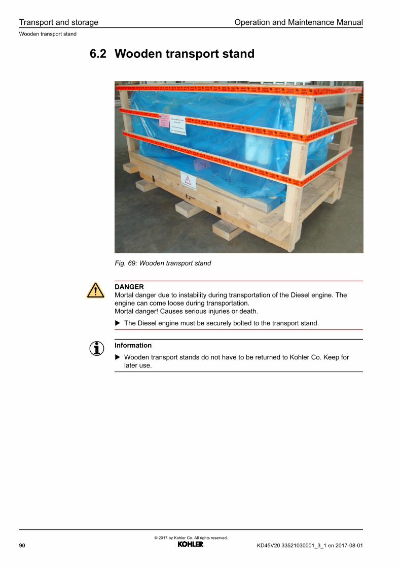
Transport and storage Operation and Maintenance ManualWooden transport stand
6.2 Wooden transport stand
Fig. 69: Wooden transport stand
DANGERMortal danger due to instability during transportation of the Diesel engine. Theengine can come loose during transportation.Mortal danger! Causes serious injuries or death.
u The Diesel engine must be securely bolted to the transport stand.
Information
u Wooden transport stands do not have to be returned to Kohler Co. Keep forlater use.
90© 2017 by Kohler Co. All rights reserved.
KD45V20 33521030001_3_1 en 2017-08-01
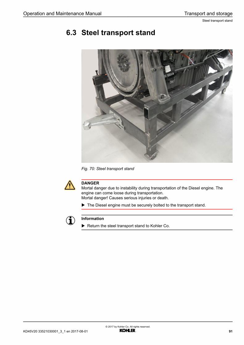
Operation and Maintenance Manual Transport and storageSteel transport stand
6.3 Steel transport stand
Fig. 70: Steel transport stand
DANGERMortal danger due to instability during transportation of the Diesel engine. Theengine can come loose during transportation.Mortal danger! Causes serious injuries or death.
u The Diesel engine must be securely bolted to the transport stand.
Information
u Return the steel transport stand to Kohler Co.
KD45V20 33521030001_3_1 en 2017-08-01© 2017 by Kohler Co. All rights reserved.
91

Transport and storage Operation and Maintenance ManualSuspension device
6.4 Suspension device
DANGERFalling load.Mortal danger! Causes serious injuries or death.
u Pay attention to the maximum weight for lifting points!
u Observe a maximum deviation of 10° between the perpendicular and the engineaxis.
u Use the Kohler lifting device.
u Dismantle the generator or other add-on parts before lifting the Diesel engine.
u Pay attention to the safety instructions / warnings in the Operating Manual forthe hoisting beam!
u Do not work under suspended loads!
Fig. 71: Suspension device
92© 2017 by Kohler Co. All rights reserved.
KD45V20 33521030001_3_1 en 2017-08-01
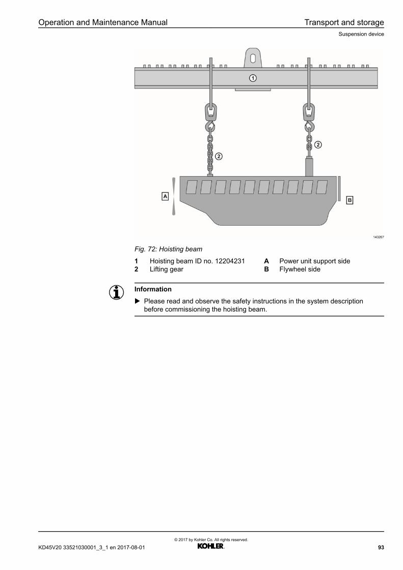
Operation and Maintenance Manual Transport and storageSuspension device
Fig. 72: Hoisting beam
1 Hoisting beam ID no. 12204231 A Power unit support side2 Lifting gear B Flywheel side
Information
u Please read and observe the safety instructions in the system descriptionbefore commissioning the hoisting beam.
KD45V20 33521030001_3_1 en 2017-08-01© 2017 by Kohler Co. All rights reserved.
93
Transport and storage Operation and Maintenance ManualStorage
6.5 Storage
6.6.1 Storage for up to 6 months
The Diesel engine is preserved from the shipping date; under normal storageconditions in a dry, well ventilated place, the conservation protection normally lastsfor 6 months.
If the Diesel engine is covered with an additional foil hood, it can also be storedoutdoors for up to one month.
The cover must be waterproof and rest loosely against the Diesel engine so that aircan circulate around the Diesel engine, thus preventing the formation of anycondensation.
A shorter conservation protection period can be expected if these measures areignored and the conserved Diesel engine is exposed to less favorable conditions(situated outdoors for longer periods of time or stored in damp, unventilatedlocations etc.).
6.7.1 Storage for over 6 and up to 24 months
Please contact Field Service if planning storage over 6 months up to 24 months.
94© 2017 by Kohler Co. All rights reserved.
KD45V20 33521030001_3_1 en 2017-08-01
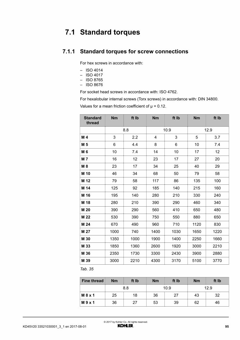
7.1 Standard torques
7.1.1 Standard torques for screw connections
For hex screws in accordance with:
– ISO 4014– ISO 4017– ISO 8765– ISO 8676
For socket head screws in accordance with: ISO 4762.
For hexalobular internal screws (Torx screws) in accordance with: DIN 34800.
Values for a mean friction coefficient of µ = 0.12.
Standardthread
Nm ft lb Nm ft lb Nm ft lb
8.8 10.9 12.9
M 4 3 2.2 4 3 5 3.7
M 5 6 4.4 8 6 10 7.4
M 6 10 7.4 14 10 17 12
M 7 16 12 23 17 27 20
M 8 23 17 34 25 40 29
M 10 46 34 68 50 79 58
M 12 79 58 117 86 135 100
M 14 125 92 185 140 215 160
M 16 195 140 280 210 330 240
M 18 280 210 390 290 460 340
M 20 390 290 560 410 650 480
M 22 530 390 750 550 880 650
M 24 670 490 960 710 1120 830
M 27 1000 740 1400 1030 1650 1220
M 30 1350 1000 1900 1400 2250 1660
M 33 1850 1360 2600 1920 3000 2210
M 36 2350 1730 3300 2430 3900 2880
M 39 3000 2210 4300 3170 5100 3770
Tab. 35
Fine thread Nm ft lb Nm ft lb Nm ft lb
8.8 10.9 12.9
M 8 x 1 25 18 36 27 43 32
M 9 x 1 36 27 53 39 62 46
KD45V20 33521030001_3_1 en 2017-08-01© 2017 by Kohler Co. All rights reserved.
95
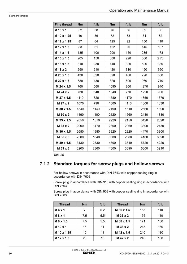
Operation and Maintenance ManualStandard torques
Fine thread Nm ft lb Nm ft lb Nm ft lb
M 10 x 1 52 38 76 56 89 66
M 10 x 1.25 49 36 72 53 84 62
M 12 x 1.25 87 64 125 92 150 110
M 12 x 1.5 83 61 122 90 145 107
M 14 x 1.5 135 100 200 150 235 173
M 16 x 1.5 205 150 300 220 360 2 70
M 18 x 1.5 310 230 440 320 520 380
M 18 x 2 290 210 420 310 490 360
M 20 x 1.5 430 320 620 460 720 530
M 22 x 1.5 580 430 820 600 960 710
M 24 x 1.5 760 560 1090 800 1270 940
M 24 x 2 730 540 1040 770 1220 900
M 27 x 1.5 1110 820 1580 1170 1850 1370
M 27 x 2 1070 790 1500 1110 1800 1330
M 30 x 1.5 1540 1140 2190 1610 2560 1890
M 30 x 2 1490 1100 2120 1560 2480 1830
M 33 x 1.5 2050 1510 2920 2150 3420 2520
M 33 x 2 2000 1470 2800 2060 3300 2430
M 36 x 1.5 2680 1980 3820 2820 4470 3300
M 36 x 3 2500 1840 3500 2580 4100 3020
M 39 x 1.5 3430 2530 4890 3610 5720 4220
M 39 x 3 3200 2360 4600 3390 5300 3910
Tab. 36
7.1.2 Standard torques for screw plugs and hollow screws
For hollow screws in accordance with DIN 7643 with copper sealing ring inaccordance with DIN 7603
Screw plug in accordance with DIN 910 with copper sealing ring in accordance withDIN 7603.
Screw plug in accordance with DIN 908 with copper sealing ring in accordance withDIN 7603.
Thread Nm ft lb Thread Nm ft lb
M 6 x 1 7 5.2 M 36 x 1.5 155 110
M 8 x 1 7.5 5.5 M 36 x 2 155 110
M 8 x 1.5 7.5 5.5 M 38 x 1.5 171 130
M 10 x 1 15 11 M 38 x 2 215 160
M 10 x 1.25 15 11 M 42 x 1.5 240 180
M 12 x 1.5 20 15 M 42 x 2 240 180
96© 2017 by Kohler Co. All rights reserved.
KD45V20 33521030001_3_1 en 2017-08-01
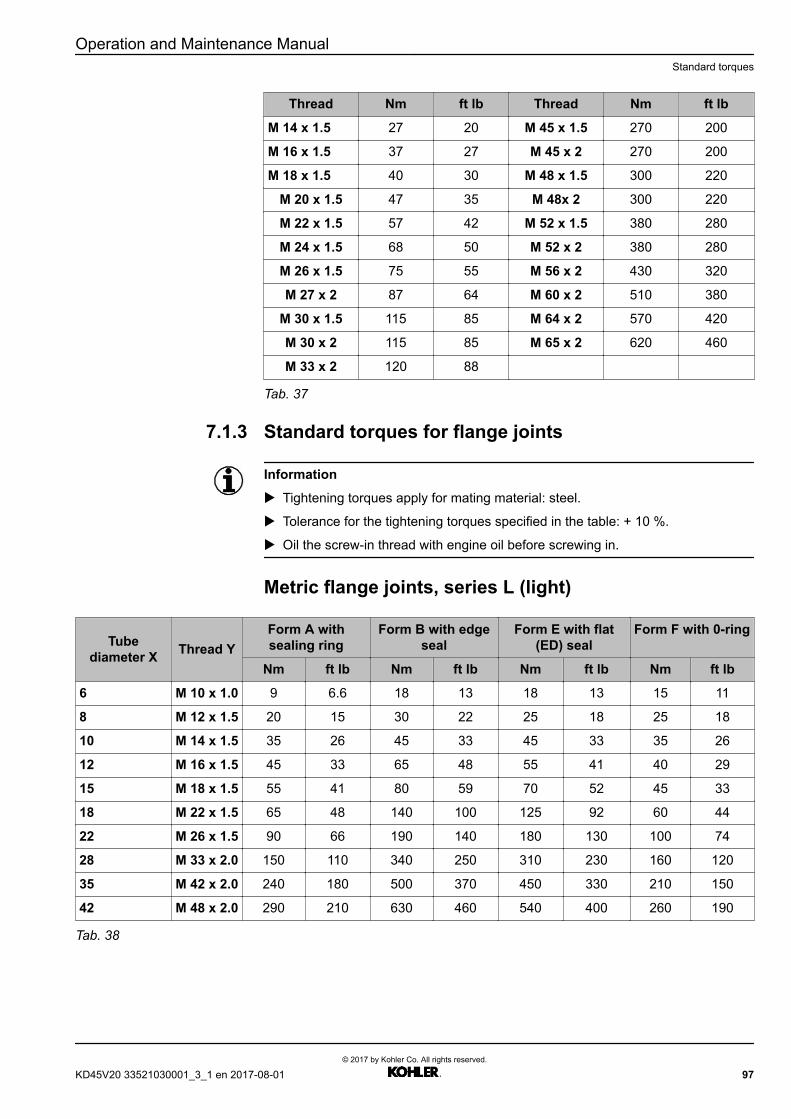
Operation and Maintenance ManualStandard torques
Thread Nm ft lb Thread Nm ft lb
M 14 x 1.5 27 20 M 45 x 1.5 270 200
M 16 x 1.5 37 27 M 45 x 2 270 200
M 18 x 1.5 40 30 M 48 x 1.5 300 220
M 20 x 1.5 47 35 M 48x 2 300 220
M 22 x 1.5 57 42 M 52 x 1.5 380 280
M 24 x 1.5 68 50 M 52 x 2 380 280
M 26 x 1.5 75 55 M 56 x 2 430 320
M 27 x 2 87 64 M 60 x 2 510 380
M 30 x 1.5 115 85 M 64 x 2 570 420
M 30 x 2 115 85 M 65 x 2 620 460
M 33 x 2 120 88
Tab. 37
7.1.3 Standard torques for flange joints
Information
u Tightening torques apply for mating material: steel.
u Tolerance for the tightening torques specified in the table: + 10 %.
u Oil the screw-in thread with engine oil before screwing in.
Metric flange joints, series L (light)
Tubediameter X Thread Y
Form A withsealing ring
Form B with edgeseal
Form E with flat(ED) seal
Form F with 0-ring
Nm ft lb Nm ft lb Nm ft lb Nm ft lb
6 M 10 x 1.0 9 6.6 18 13 18 13 15 11
8 M 12 x 1.5 20 15 30 22 25 18 25 18
10 M 14 x 1.5 35 26 45 33 45 33 35 26
12 M 16 x 1.5 45 33 65 48 55 41 40 29
15 M 18 x 1.5 55 41 80 59 70 52 45 33
18 M 22 x 1.5 65 48 140 100 125 92 60 44
22 M 26 x 1.5 90 66 190 140 180 130 100 74
28 M 33 x 2.0 150 110 340 250 310 230 160 120
35 M 42 x 2.0 240 180 500 370 450 330 210 150
42 M 48 x 2.0 290 210 630 460 540 400 260 190
Tab. 38
KD45V20 33521030001_3_1 en 2017-08-01© 2017 by Kohler Co. All rights reserved.
97

Operation and Maintenance ManualStandard torques
Tubediameter X Thread Y
WH TH SWVE
Nm ft lb Nm ft lb Nm ft lb
6 M 10 x 1.0 18 13 18 13 18 13
8 M 12 x 1.5 45 33 45 33 35 26
10 M 14 x 1.5 55 41 55 41 50 37
12 M 16 x 1.5 80 59 80 59 60 44
15 M 18 x 1.5 100 74 100 74 80 59
18 M 22 x 1.5 140 100 140 100 120 89
22 M 26 x 1.5 320 240 320 240 130 96
28 M 33 x 2.0 360 270 360 270
35 M 42 x 2.0 540 400 540 400
42 M 48 x 2.0 700 520 700 520
Tab. 39
Metric flange joints, series S (heavy)
Tubediameter X Thread Y
Form A with sealing ring Form B with edge seal Form E with flat (ED) seal
Nm ft lb Nm ft lb Nm ft lb
6 M 12 x 1.5 20 15 35 26 40 29
8 M 14 x 1.5 35 26 55 41 40 29
10 M 16 x 1.5 45 33 70 52 70 55
12 M 18 x 1.5 55 41 110 81 90 66
14 M 20 x 1.5 55 41 150 110 125 92
16 M 22 x 1.5 65 48 170 120 135 100
20 M 27 x 2.0 90 66 270 200 180 130
25 M 33 x 2.0 150 110 410 300 310 230
30 M 42 x 2.0 240 180 540 400 450 330
38 M 48 x 2.0 290 210 700 520 540 400
Tab. 40
Tubediameter X Thread Y
WH TH SWVE
Nm ft lb Nm ft lb Nm ft lb
6 M 12 x 1.5 45 33 45 33 35 26
8 M 14 x 1.5 55 41 55 41 50 37
10 M 16 x 1.5 80 59 80 59 60 44
12 M 18 x 1.5 100 74 100 74 80 59
14 M 20 x 1.5 125 92 125 92 110 81
16 M 22 x 1.5 135 100 135 100 120 88
20 M 27 x 2.0 320 240 320 240 135 100
98© 2017 by Kohler Co. All rights reserved.
KD45V20 33521030001_3_1 en 2017-08-01
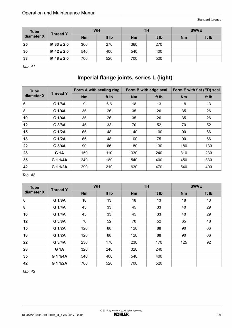
Operation and Maintenance ManualStandard torques
Tubediameter X Thread Y
WH TH SWVE
Nm ft lb Nm ft lb Nm ft lb
25 M 33 x 2.0 360 270 360 270
30 M 42 x 2.0 540 400 540 400
38 M 48 x 2.0 700 520 700 520
Tab. 41
Imperial flange joints, series L (light)
Tubediameter X Thread Y
Form A with sealing ring Form B with edge seal Form E with flat (ED) seal
Nm ft lb Nm ft lb Nm ft lb
6 G 1/8A 9 6.6 18 13 18 13
8 G 1/4A 35 26 35 26 35 26
10 G 1/4A 35 26 35 26 35 26
12 G 3/8A 45 33 70 52 70 52
15 G 1/2A 65 48 140 100 90 66
18 G 1/2A 65 48 100 75 90 66
22 G 3/4A 90 66 180 130 180 130
28 G 1A 150 110 330 240 310 230
35 G 1 1/4A 240 180 540 400 450 330
42 G 1 1/2A 290 210 630 470 540 400
Tab. 42
Tubediameter X Thread Y
WH TH SWVE
Nm ft lb Nm ft lb Nm ft lb
6 G 1/8A 18 13 18 13 18 13
8 G 1/4A 45 33 45 33 40 29
10 G 1/4A 45 33 45 33 40 29
12 G 3/8A 70 52 70 52 65 48
15 G 1/2A 120 88 120 88 90 66
18 G 1/2A 120 88 120 88 90 66
22 G 3/4A 230 170 230 170 125 92
28 G 1A 320 240 320 240
35 G 1 1/4A 540 400 540 400
42 G 1 1/2A 700 520 700 520
Tab. 43
KD45V20 33521030001_3_1 en 2017-08-01© 2017 by Kohler Co. All rights reserved.
99
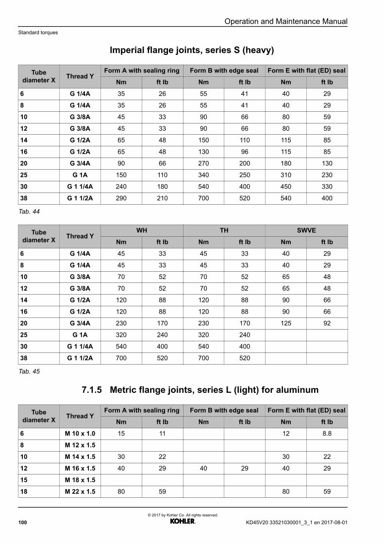
Operation and Maintenance ManualStandard torques
Imperial flange joints, series S (heavy)
Tubediameter X Thread Y
Form A with sealing ring Form B with edge seal Form E with flat (ED) seal
Nm ft lb Nm ft lb Nm ft lb
6 G 1/4A 35 26 55 41 40 29
8 G 1/4A 35 26 55 41 40 29
10 G 3/8A 45 33 90 66 80 59
12 G 3/8A 45 33 90 66 80 59
14 G 1/2A 65 48 150 110 115 85
16 G 1/2A 65 48 130 96 115 85
20 G 3/4A 90 66 270 200 180 130
25 G 1A 150 110 340 250 310 230
30 G 1 1/4A 240 180 540 400 450 330
38 G 1 1/2A 290 210 700 520 540 400
Tab. 44
Tubediameter X Thread Y
WH TH SWVE
Nm ft lb Nm ft lb Nm ft lb
6 G 1/4A 45 33 45 33 40 29
8 G 1/4A 45 33 45 33 40 29
10 G 3/8A 70 52 70 52 65 48
12 G 3/8A 70 52 70 52 65 48
14 G 1/2A 120 88 120 88 90 66
16 G 1/2A 120 88 120 88 90 66
20 G 3/4A 230 170 230 170 125 92
25 G 1A 320 240 320 240
30 G 1 1/4A 540 400 540 400
38 G 1 1/2A 700 520 700 520
Tab. 45
7.1.5 Metric flange joints, series L (light) for aluminum
Tubediameter X Thread Y
Form A with sealing ring Form B with edge seal Form E with flat (ED) seal
Nm ft lb Nm ft lb Nm ft lb
6 M 10 x 1.0 15 11 12 8.8
8 M 12 x 1.5
10 M 14 x 1.5 30 22 30 22
12 M 16 x 1.5 40 29 40 29 40 29
15 M 18 x 1.5
18 M 22 x 1.5 80 59 80 59
100© 2017 by Kohler Co. All rights reserved.
KD45V20 33521030001_3_1 en 2017-08-01
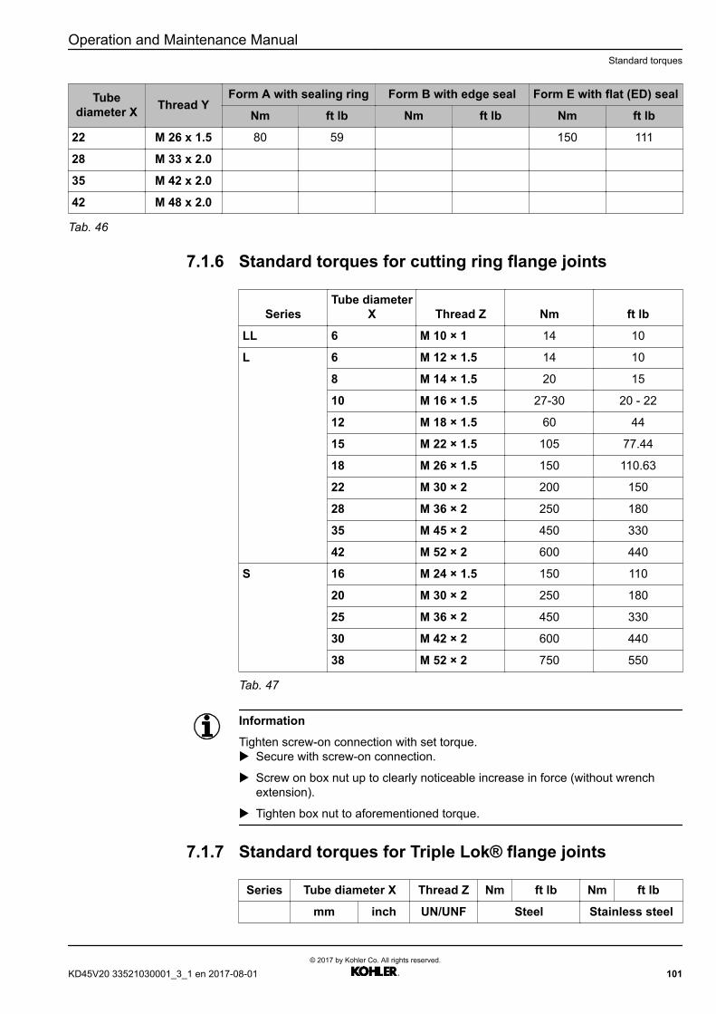
Operation and Maintenance ManualStandard torques
Tubediameter X Thread Y
Form A with sealing ring Form B with edge seal Form E with flat (ED) seal
Nm ft lb Nm ft lb Nm ft lb
22 M 26 x 1.5 80 59 150 111
28 M 33 x 2.0
35 M 42 x 2.0
42 M 48 x 2.0
Tab. 46
7.1.6 Standard torques for cutting ring flange joints
SeriesTube diameter
X Thread Z Nm ft lb
LL 6 M 10 × 1 14 10
L 6 M 12 × 1.5 14 10
8 M 14 × 1.5 20 15
10 M 16 × 1.5 27-30 20 - 22
12 M 18 × 1.5 60 44
15 M 22 × 1.5 105 77.44
18 M 26 × 1.5 150 110.63
22 M 30 × 2 200 150
28 M 36 × 2 250 180
35 M 45 × 2 450 330
42 M 52 × 2 600 440
S 16 M 24 × 1.5 150 110
20 M 30 × 2 250 180
25 M 36 × 2 450 330
30 M 42 × 2 600 440
38 M 52 × 2 750 550
Tab. 47
Information
Tighten screw-on connection with set torque.u Secure with screw-on connection.
u Screw on box nut up to clearly noticeable increase in force (without wrenchextension).
u Tighten box nut to aforementioned torque.
7.1.7 Standard torques for Triple Lok® flange joints
Series Tube diameter X Thread Z Nm ft lb Nm ft lb
mm inch UN/UNF Steel Stainless steel
KD45V20 33521030001_3_1 en 2017-08-01© 2017 by Kohler Co. All rights reserved.
101

Operation and Maintenance ManualStandard torques
4 6 1/4 7/17-20 15 11 30 22
5 8 5/16 1/2-20 20 15 40 29
6 10 3/8 9/16-18 30 22 60 44
8 12 1/2 3/4-16 60 44 115 85
10 14, 15, 16 5/8 7/8-14 75 55 145 110
12 18, 20 3/4 1 1/16-12 110 81 180 130
16 22 7/8 1 5/16-12 135 100 225 170
16 25 1 1 5/16-12 175 130 255 190
28 1 5/8-12 260 190 295 220
20 30, 32 1 1/4 1 5/8-12 260 190 295 220
35 1 7/8-12 340 250 345 250
24 38 1 1/2 1 7/8-12 340 250 345 250
28 42 - 2 1/4-12 380 280 400 290
32 - 2 2 1/2-12 450 330 470 350
Tab. 48
Information
Tighten screw-on connection with set torque.u Secure with screw-on connection.
u Screw on box nut up to clearly noticeable increase in force (without wrenchextension).
u Tighten box nut to aforementioned torque.
7.1.8 Standard torques for VSTI screw plugs
Thread Nm ft lb Thread Nm ft lb
M 10 x 1 10 7.4 M 26 x 1.5 100 74
M 12 x 1.5 20 15 M 27 x 2 120 88
M 14 x 1.5 30 22 R 3/4” 120 88
M 16 x 1.5 40 29 M 30 x 1.5 120 88
M 18 x 1.5 50 37 M 33 x 2 200 150
M 20 x 1.5 60 44 M 38 x 1.5 280 210
M 22 x 1.5 80 59 M 42 x 2 350 260
M 24 x 1.5 90 66 M 48 x 2 400 290
Tab. 49
102© 2017 by Kohler Co. All rights reserved.
KD45V20 33521030001_3_1 en 2017-08-01

Operation and Maintenance ManualSpecial tool
7.2 Special tool
Description ID no. Order number
TURNING DEVICE 10123791 230610006
1 Hoisting beam 12204231 230610044
Tab. 50: Special tool with identification number
KD45V20 33521030001_3_1 en 2017-08-01© 2017 by Kohler Co. All rights reserved.
103

Operation and Maintenance ManualTerms used (glossary)
7.3 Terms used (glossary)
Term Explanation
Ready for use The engine is ready for starting.
Emission optimized Exhaust gas optimized
Fuel optimized Fuel optimized
Device manufacturer The manufacturer of the overall plant in which the Dieselengine is installed.
In operation The engine is running.
Safety zone Designated area around the engine, access to which in thevarious operating modes is described in the chapter on"Operating and maintenance areas".
Maintenance areas Maintenance areas are the safety zones that have to beaccessed for maintenance work and troubleshooting.
Tab. 51
104© 2017 by Kohler Co. All rights reserved.
KD45V20 33521030001_3_1 en 2017-08-01

Index
AAdditional markings 19Approved fuel qualities 40
BBattery charging alternator 18Bruises 23Burns and scalding 23
CChange air filter main element 81Check and change the V-ribbed belt for the batterycharging alternator 84Check coolant level 69Check state of fan drive belt drive and replace ifnecessary 81Check the ventilation holes on the water pump. 70Check/drain water trap on the primary fuel filter 70Checking the engine oil level 67Checking the V-ribbed belt 82Continuous operating power (COP) 45Coolant 43Coolant thermostat 18COP Emission optimized — Service level 1 61COP Emission optimized — Service level 2 62COP Fuel optimized — Service level 1 59COP Fuel optimized — Service level 2 60Crankcase breather position 76Cylinder head 17
DDaily, weekly and monthly maintenance work 46, 65Danger due to noise 25Design overview 11Diesel engine 17Diesel engine company name plate 14Diesel fuels 40Difficulty factors 42Draining the diesel engine oil 73
EElectrical energy 25Emergency standby power system (ESP) 45Emergency stop 29
Engine control unit nameplate 15Engine oil analysis 43Engine oil change intervals: 42Engine oils 41Engine serial number 14Errors – Cause – Remedy 33ESP 50Hz emission optimized top power — Servicelevel 1 51ESP 50Hz emission optimized top power — Servicelevel 2 52ESP Emission optimized — Service level 1 49ESP Emission optimized — Service level 2 50ESP Fuel optimized — Service level 1 47ESP Fuel optimized — Service level 2 48Explanation of the type designation 14
FFastening during transport 88Fill quantities 39Filling the operating fluids 31Filling with diesel engine oil 75Fires and explosions 24Flywheel housing 18Foreseeable misuse 22
GGeneral safety instructions 22
HHandling, operation 31High-pressure injection (liquids at high pressure cansquirt out) 24
IIdentification of the warnings 19Imperial flange joints, series L (light) 99Imperial flange joints, series S (heavy) 100Index 105Install oil separator filter insert 77International standard classification of occupations 20
LLubricants and operating materials 39, 40
MMaintenance activities 72Maintenance areas 27Maintenance schedule 45Maintenance schedule — COP Emissionoptimized 61Maintenance schedule — COP Fuel optimized 59
KD45V20 33521030001_3_1 en 2017-08-01© 2017 by Kohler Co. All rights reserved.
105

Index Operator's manual
Maintenance schedule — ESP 50Hz emissionoptimized top power 51Maintenance schedule — ESP Emissionoptimized 49Maintenance schedule — ESP Fuel optimized 47Maintenance schedule — PRP 50Hz emissionoptimized top power 57Maintenance schedule — PRP Emissionoptimized 55Maintenance schedule — PRP Fuel optimized 53Maintenance Technician 20Metric flange joints, series L (light) 97Metric flange joints, series L (light) for aluminum 100Metric flange joints, series S (heavy) 98Minimum requirement for quality 41
NNominal values for the power generating unit 45
OOccupational references 20Operating areas 27Operating areas and maintenance areas 26Operating faults 33Operating fluids and maintenance 39Operator 21Overview of sensors 13
PPerformance requirements of the qualitycategories 41Personal protective equipment 25Poisoning 24Preparatory maintenance activities 64Prevent material damages 30Preventing personal injuries 23Prime power (PRP) 45Product description 11PRP 50Hz emission optimized top power — Servicelevel 1 57PRP 50Hz emission optimized top power — Servicelevel 2 58PRP Emission optimized — Service level 1 55PRP Emission optimized — Service level 2 56PRP Fuel optimized — Service level 1 53PRP Fuel optimized — Service level 2 54
RRemove oil separator filter insert 77Replace diesel engine oil and oil filter 72Replace main fuel filter 78Replace the oil separator filter insert of the crankcasebreather 75Replace the primary fuel filter 80
Replacing the belt 82, 84Replacing the oil filter 74Requirements for water 43Requirements of the coolant 44
SSafety 19Safety instructions 26Secure and release the diesel engine againstaccidental starting 28Selecting the engine oil 41Service Assistance 9Signage 29Special tool 103Special tools for maintenance activities 63Standard torques 95Standard torques for cutting ring flange joints 101Standard torques for flange joints 97Standard torques for screw connections 95Standard torques for screw plugs and hollowscrews 96Standard torques for Triple Lok® flange joints 101Standard torques for VSTI screw plugs 102Starter 18Starting the engine 31Start-up procedure 31Steel transport stand 91Storage 94Storage for over 6 and up to 24 months 94Storage for up to 6 months 94Suspension device 92
TTake coolant sample and perform coolantanalysis. 80Take oil sample and perform oil analysis 72Target audience 19Technical data 17Technical description 11Technician 20Terms used (glossary) 104Time between overhauls (TBO) 45Transport and storage 87Type description 14
UUnauthorized personnel 21
WWooden transport stand 90
106© 2017 by Kohler Co. All rights reserved.
KD45V20 33521030001_3_1 en 2017-08-01


33521030001_3_1 EN 07-2017 LHID11433947 ©2016 by Kohler Co. All rights reserved.