OPERATION AND MAINTENANCE MANUAL FOR SOLAR WATER HEATING ... · required in the heating system and...
16
HEAT TRANSFER MANUAL FOR SOLAR WATER HEATING SYSTEM OPERATION AND MAINTENANCE
Transcript of OPERATION AND MAINTENANCE MANUAL FOR SOLAR WATER HEATING ... · required in the heating system and...

HEAT TRANSFER
MANUAL FOR SOLAR WATER HEATING SYSTEM
OPERATION AND MAINTENANCE

QU ALITY WITHOUT COMPROMISE
HE AT TRANSFER
HRSFUNKE SOLAR SYSTEM MANUAL
GENERAL INFORMATION AND WARNINGS
INSTALLATION
This instruction manual is an integral and essential part of the product. Check that it is always together with the solar panel system.
Read carefully the instructions contained in this chapter for a correct and safe installation and start up of the unit. After installation, give this instruction manual to the end-user.
The installation and start up must be performed by professionally qualified technicians having the specific skills required in the heating system and solar sector.
A wrong installation of the system can cause damages to systems, for which HRSFUNKE is not responsible.
Adequate safety norms shall be followed to ensure safety installation.When near to high tension electrical conducts, installation can be done only if:
– the involved line has been disconnected; be sure that itwill remain disconnected until installation will be finished;– the under tension parts have been protected with thenecessary systems;
– the involved line is at a safety distance given in relationto its tension in V, if line tension is not known, it has to be at least 5 meters far away.The NON respect of the safety distance can cause even deadly accidents.
Protect from sunshine, during mounting, the connecting pipes and the panel’s accessories; because these parts heated could cause dangerous burns with contact.
Use adequate accident prevention measures:– shoes for accident prevention,– glasses to protect eyes from sun, shaving and slivers,– gloves to protect hands and fingers from eventual cut,– helmet.
HRS FUNKE solar panel, with the relevant installation’s accessories, can be mounted, with multiple of two or three panels, in flat surface, or on sloping roof with the same pitch’ slope, on sloping roof with further angle of 20°in comparison to pitch. The fixing system to the roof pitchcan be with bar under tile or with pass through pin.
The solar panel is supplied packed in a strong carton box. The first thing to do is to check product’s integrity. In case of doubt do not use the unit and contact the supplier.
The collector’s move has to be done keeping the glass side on the top.
Installation on roof has to be done after a careful evaluation on the roof’ strength, considering the total weight of pan-els, frame and hydraulic pipes fittings’ weight. In particular check the underneath structure considering that panel/s’ fixing will be done to it.
Series accessories for installation are sufficient for the fol-lowing mounting conditions:– Panel slope shall be 45°angle– maximum building’s height measured from ground, 25 mt.,– max. wind force 150 km/h.For different conditions, have a qualified technician make the static calculation of the structure.
To optimize the solar panels’ performance, choose the roof’s pitch at South with the help of a compass or accord-ing to the sun’s position at 12:00 o’clock a.m..
In case the South position is not possible, it has to be cho-sen the South-West orientation instead of the South-East, with shifting from the South cardinal point possibly over 15°.
Keep in consideration that shifting until 15° do not cause substantial efficiency losses; 15° correspond to the sun seeming move in one hour.
The appliance has to be installed perpendicular to the rays of sunlight.
By installation pay attention to the shade areas caused by buildings and plants, that can highly reduce the sunshine hours
In case more panels’ lines are installed, to avoid that the first line make shade to the back ones, the minimum distance between the lines have to be maintained.
QU ALITY WITHOUT COMPROMISE
HE AT TRANSFER
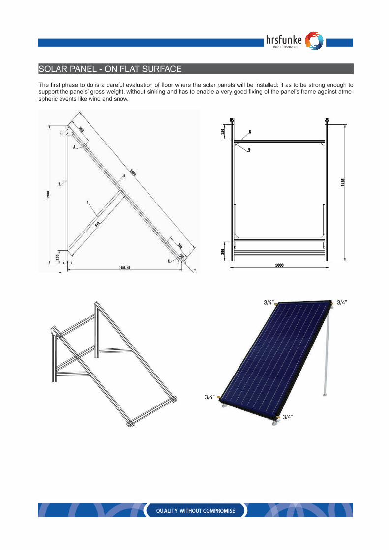
SOLAR PANEL - ON FLAT SURFACE
The first phase to do is a careful evaluation of floor where the solar panels will be installed: it as to be strong enough to support the panels’ gross weight, without sinking and has to enable a very good fixing of the panel’s frame against atmo-spheric events like wind and snow.
3/4”3/4”
3/4”
3/4”

TECHNICAL DETAILS
QUALITY WITHOUT COMPROMISE
HEAT TRANSFER
MODEL FPC2.0 - Vertical FPC2.4 - Vertical FPC2.4 and 3.0
FEATURES
ABSORBER
THERMAL INSULATION
CASING
Dimension (h) x (w) x (d)
Gross Area (m2)
Aperture Area (m2)
Cover material
Cover thickness
Weight
Fulid Volume of Absorber
2000 x 1000 x 80mm
2
1.86
-
-
35kg
1.6 Litre
2000 x 1200 x 80mm
2.4
2.39
Frosted Low Iron Tempered glass
3.5mm
40kg
1.6 Litre
2000 x 1500 x 80mm
3.0
2.39
-
-
50kg
1.6 Litre
Sensor pocket
Panel orientation
Material
Surface treatment
Absorption Factor
Emissions
Header material
Header tube size
Riser tube size
Design Welding
Maximum Pressure
Frame
Frame color
Fram thickness
Back plate
Max operating temperature
Transfer coeffient
Sealing gasket
Insulation Material
Insulation thickness
Built in sensor pocket
Vertical
Polyester fiber
35mm
Polyester fiber
35mm
Polyester fiber
35mm
6063 Aluminum alloy
Antique bronze
1mm
chromodek
< 200 °C (153 °C)
> 95 2%
EPDM
6063 Aluminum alloy
Antique bronze
1mm
chromodek
< 200 °C (153 °C)
> 95 2%
EPDM
6063 Aluminum alloy
Antique bronze
1mm
chromodek
< 200 °C (153 °C)
> 95 2%
EPDM
Built in sensor pocket
Vertical
Built in sensor pocket
Vertical
Copper-Aluminum fin
Black Chrome
85 5%
5 2%
Copper
22mm x 0.75mm
Copper
Ultrasonic Welding
10 Bar
Copper-Aluminum fin
Black Chrome
85 5%
5 2%
Copper
22mm x 0.75mm
Copper
Ultrasonic Welding
10 Bar
Copper-Aluminum fin
Black Chrome
85 5%
5 2%
Copper
22mm x 0.75mm
Copper
Ultrasonic Welding
10 Bar
HRSFUNKE STANDARD FLAT PLATE COLLECTORS

QU ALITY WITHOUT COMPROMISE
HE AT TRANSFER
INSTALLATION INSTRUCTIONS
– Put the second panel near the first one spacing enough to enable hydraulicconnection putting the joint-trim in between and turning the pipe fitting ring.
– Only now it is suggested to screw up the fixing screws of the frames to thesupporting T shaped bars.For hydraulic installation see relative paragraph.
Dp [mbar]
140
120
100
80
60
40
20
0 100 200 300 400 500 V [l/h]
The connection of more than one solar will be in series double and/or in parallel, with natural or forced circulation, according to the required load loss; for the in series double connection see the drawing on the left of this page.
Consider what follows for the surface where the in series solar panels are located:– the distance between two installed collectors is 34 mm.,– leave a space of approx. 100 mm. to the external side solar panels for the connections to the solar system.
To calculate system’s load losses, see the here below diagram keeping in consideration what follows:– the showed diagram is valid for a single solar panel,– the circulation is forced,– the test liquid is water + 33% glycol at 20°C temperature.
In any case connect maximum nr. 8 solar panels in double series and maximum nr. 10 solar panels in parallel.Foresee the inlet pipe fitting more or less as long as and like the return pipe fitting, so that all panels work at the same conditions.
– The maintenance should be carried out as per HRSFUNKE instructions and should be done by HRSFUNKE personnelsonly for the warranty to be valid as per the terms and conditions mentioned in the warranty.

QU ALITY WITHOUT COMPROMISE
HE AT TRANSFER
STORAGE CALORIFIER
– Use lifting lugs where fitted.– Do not lift a vessel using the insulation where fitted.– Straps may crush or damage the insulation casing.– Due to the insulation casing material thickness, care should be taken when moving and handling the vessel not to
damage the insulation.– Do not lift the vessel using chains directly in contact with the shell.– Do not allow operatives to stand on the vessel
– Foundations or plinths must be firm and level to prevent settling,pipe strain or distortion of the shell.– Unless specifically ordered differently, the vessel must be installedin a level position.– Protective covers and plugs may be fitted to connections to protectthem in transit. These must be removed prior to use.– If a connection is not required, seal it appropriately.– Check for any foreign material which may have got into the vessel.– Pipework connected to the vessel must be adequately supported toprevent any loads being transmitted to the vessel. – Provide for thermal expansion with bends and expansion joints.– Fit isolation valves prior to the vessel connections to facilitateservicing (NOT TO THE VENT). – For flanged connections, tighten bolts in a diametrically oppositesequence to load the flanges evenly onto the gasket. – Ensure adequate venting for air removal during filling and operation(pressurized systems should have an automatic air vent and a manual air vent for this).– Safety valves should have their discharge pipes away to a safedisposal point, preferably via an air-break and tundish so that the discharge unrestricted and easily visible. –
–
The maintenance should be carried out as per HRSFUNKE instruc-tions and should be done by HRSFUNKE personnels only for the warranty to be valid as per the terms and conditions mentioned in the warranty
Type of shell materialCopper Lined Carbon Steel – Glass Lined Carbon Steel
– Stainless Steel SS 316 L – Stainless Steel SS 304
.
LIFTING & HANDLING:
POSITIONING:
To optimize the solar panel’s performance connect the return panels’ pipes to bottom connection and the inlet to the upperone.
For hydraulic connections of solar panels’ installation, see the installation diagram.
On the return pipe, foresee a safety valve set at 6 bar, an expansion vessel sealed by membrane to avoid primary fluiddilatation, an hydrometer, necessary for loading phase and a flow-control valve.Furthermore, near the panel foresee the connection for antifreeze liquid’s loading.
Install the circulation electro-pump with interception valves on the inlet pipes, when natural circulation of primary fluid is not feasible, and near the solar panel, foresee the solar panel’s probe for electro-pump electronic panel’s control and a relief valve, necessary for solar circuit’s loading. The solar panel’s probe has to be positioned so that to measure the solar fluid’s temperature at the solar panel’s outlet also with not working circulator.
On the lowest circuit’s point install a loading group and on the highest point an additional relief valve, (if solar panels are installed on roof, consequently being at the highest point of installation, the second relief valve is not necessary).Packing (like carton box, plastic bag, etc.), do not have to be left away because are dangerous.

QU ALITY WITHOUT COMPROMISE
HE AT TRANSFER
CIRCULATION PUMP
EXPANSION TANK
– Close the supply water valve to the water heater located, in mostcases, above the water heater on the cold water inlet to the hot water heater.– Drain the water from the hot water pipe. Let the water run until itstops flowing. Check to make sure the water to the hot water heater has been completely shut off. – Disconnect the hot water heater at the hot water discharge.– Install pump onto the water heater discharge, using pipefitting. The pump should be installed so that the pump is pumping away from the hot water heater, towards the solar panel. Confirm the direction of pumping by observing the flow arrow on the side of the pump housing. – Connect the hot water line to the discharge of the pump.– Reopen the supply valve to the hot water heater and allow thewater to run until all the air has been purged from the piping.
– Please check carefully whether the pre-set gas pressure is suitablefor your system.– If necessary pre-set gas pressure must be adjusted.– If you apply a pre-set gas pressure that is higher than the maximumoperation pressure of the tank, or when the tank is filled with pres-surized water from the installation, that is higher than the maximum operation pressure of the tank; this may lead to damage to the tank or the people and goods around it. Our company cannot be held liable for such accidents and damages.– The permitted values given for operation and pre-set gas fillingmust not be exceed under no condition. During the filling of the pre-set gas no other gas must be used other than air or nitrogen.– Please install the expansion tank in a no-frost area, where valveand label is perfectly visual. If necessary fix the feet of the vessel with the help of screws on the floor.– In heating systems the expansion tank must be connected to the return line of the solar. It
should be situated near to the solar as well.– Please leave sufficient room on both sides of the vessel for any service application.
– If the pipe between the vessel and the solar is removable it will facilitate the service application.
– The diameter of the pipe between the expansion tank and the solar must be equal to the tank connection diameter. A safety valve that is suitable with the solar operation pressure should be installed. (If there is no safety valve on other point of the installation then one must be installed in any case.)
– Do not bury the feet of the vessels into concrete because in some cases the vessel must be lied down to perform a service application.
– EPDM membranes can be advised for use with water/glycol mixtures up to 50%.
– The maintenance should be carried out as per HRSFUNKE instructions and should be done by HRSFUNKE personnels only for the warranty to be valid as per the terms and conditions mentioned in the warranty.
Note:We are using pre cool tank inline with expansion vessel for the protection of rubber bladder in the exapnsion vessel, this will only allow cold water to pass through the expansion tank.
– Plug the line cord of pump into a 115V outlet. Be sure to route the power cord so that it does not touch the exhaust vent piping of a gas or oil fired hot water heater.– Set the pump to operate around your peak use times.– The maintenance should be carried out as per HRSFUNKE instructions and should be done by HRSFUNKE personnelsonly for the warranty to be valid as per the terms and conditions mentioned in the warranty.

QU ALITY WITHOUT COMPROMISE
HE AT TRANSFER
IMMERSION HEATER CONTROL THERMOSTAT
– The immersion heaters are tested before leaving the factory and are ready for installation.– The immersion heaters are thoroughly dried prior to dispatch but moisture may collect in the heater during transit or sitestorage.– It is important that prior to connecting the heaters to the mains, an insulation test must be made across each element toearth.If the insulation resistance is less than 50,000 Ohms, the heaters must be dried out prior to connection. – This can be done by placing the heaters in a low temperature oven or by passing a low voltage (maximum of 25% of theworking voltage) through the elements in open air to a maximum temperature of 60°C. – The heaters should be switched off at regular intervals to prevent overheating.– For further instructions contact HRS.
CONTROL THERMOSTAT:
HIGH LIMIT/SAFETY INTERLOCK:
Each Storage Calorifier is with equipped with Back up Electrical Heater. Each Heater is with Thermostats control, Control Thermostat is for the normal operation, based on which the heater On-Off to maintain the setting temperature. Heater is also connected with High Temperature/Over Heater Thermostat. This will ensure the heater will not over heat the second-ary water, also if the heater run dry, this thermostat will product from heater damage.
You can adjust the control thermostat manually at any time, even without switching of thee system. Black color setting point is available above the heater with setting 30 -85 C. You can simply rotate the same to change the setting.
The High Temperature Thermostat, is in built in the heater, and whenever the heater temperature is Very high, or if the heat-er runs dry thee interlock works and will trip the electrical heater. During this time heating will be only by the Solar. Heater can be bring to operation by resetting the safety Interlock, for this shall shutdown the system and need to open the heater box. Nearer to the connecter inside you can find black spring button and that need press down for the reset. After resetting the system can be operated in normal.
– The maintenance should be carried out as per HRSFUNKE instructions and should be done by HRSFUNKE personnelsonly for the warranty to be valid as per the terms and conditions mentioned in the warranty.
IMMERSION HEATER

QU ALITY WITHOUT COMPROMISE
HE AT TRANSFER
SOLAR CONTROL PANEL
SOLAR CHOICE CONTROL DETAILS
WIRE ARRANGEMENTDepending on the type of installation, the cables may enter the controller through the rear hole of the caseA or the lower side hole of the case B.
Cable comes from the rear hole A: Remove the plastic flaps from the rear side of the case using an appropriate tool.
Cable comes from the below hole B: Cut the left and right plastic flaps using an appropriate tool (e.g. knife) and break them out of the case.
Notes: the flexible wire must be fastened on the case using the clamps provided
– The maintenance should be carried out as per HRSFUNKE instruc-tions and should be done by HRSFUNKE personnels only for the warran-ty to be valid as per the terms and conditions mentioned in the warranty.
WIRE CONNECTION
Before opening the terminal, please be sure to switch-off the power and pay attention to the local electricity supply rules.
Input Ports
Inputs T0~T1: For PT1000 temperature sensor, used for measuring the temperature of collector and measuring the pro-duced. thermal energy.
T0:No connectionT1-TSolar
Inputs T2~T6: for NTC10K, B=3950 temperature sensor, used for measuring the temperature of storageor pipe.
T4~T6 No connection
T2-Tank1, T3-Tank2

QU ALITY WITHOUT COMPROMISE
HE AT TRANSFER
ADVICE REGARDING THE INSTALLATION OF TEMPERATURE SENSORS
OUTPUT PORTS
• Only original factory enclosed Pt1000 temperature sensors are approved for use with the collector, it is equipped with1.5meter silicon cable and suitable for all weather conditions, the temperature sensor and cable are temperature resistant up to 280oC, not necessary to distinguish the positive and negative polarity of the sensor connection.
• Only original factory enclosed NTC10K, B=3950 temperature sensors are approved for use with tank and pipe, it isequipped with 1.5meter PVC cable, and they are temperature resistant up to 105oC, not necessary to distinguish the pos-itive and negative polarity of the sensor connection.
• All sensor cables carry low voltage, and to avoid inductive effects, must not be laid close to 230 volt or 400-volt cables(minimum separation of 100mm)
• If external inductive effects are existed, e.g. from heavy current cables, overhead train cables, transformer substations,radio and television devices, amateur radio stations, microwave devices etc, then the cables to the sensors must be ade-quately shielded.
• Sensor cables may be extended to a maximum length of ca. 100 meter, when cable’s length is up to 50m, and then0.75mm2 cable should be used. When cable’s length is up to 100m, and then 1.5mm2 cable should be used.
Input Ports: Input ports L, N is power connection terminal,
please connect correctly is Ground line terminal.
Output P1: Semiconductor relay (SCR relay), for solar circuit pump, also suitable for RPM (speed) control;Max. Switching current: 1A.
Output P2: Semiconductor relay (SCR relay), for solar circuit pump, also suitable for RPM (speed) control;Max. Switching current: 1A.
Output H1: Electromagnetic relay and Max. Switching current 3.5A,Output R1: Electromagnetic relay and Max. Switching current 3.5A, for T type electromagnetic valve
Note:• R1 used for controlling the electromagnetic valve, and
“COM NC” is always the closed port,
“COM NO” is always the open port.
• If this port is used for control circuit pump , Circuit pump isconnected to port “COM NO” (always openvalve).
• Depending on the solar system selection, pump and sen-sors should be connected to the controller are different, all wires should be installed in protection pipe.

QU ALITY WITHOUT COMPROMISE
HE AT TRANSFER
SCH (2 STORAGES, RESERVE PUMP CONTROL LOGIC)
SYSTEM DESCRIPTION:
Controller compares the temperature between collector T1 and storage1T2(T1), storage2 T3(ΔT2), if the temperaturedifference DT rises up to or exceeds its preset switch-on DT, then the corresponding circuit pump P1 is triggered to heat storage until DT drops to the switch-off DT then circuit pump P1 is ceased.Reserve pump P2 circulation:
If the temperature difference ΔT(T1,T2) and ΔT(T1,T4) reach swtich on,Pump Timing control activated:p1 operation(adjustable 1,60min) mins, then off, After then,P2 operation t(adjustable 1,60min) mins, then stop it. do like this,P1 and P2 alternate operation till when the temperature differnce ΔT reach switch off.
Note: every time, start with P1,t adjustable(1,60mins),factory default=15mins.

QU ALITY WITHOUT COMPROMISE
HE AT TRANSFER
COMMISSIONING
Once installation and testing complete, commissioning should take place. Commissioning should be carried out by com-petent engineers.
1. Turn on the power to the control panel and ensure all items including the pump and control valve are live. The panelsystem switch should be set at ‘Off’
2. Switch the panel system switch to ‘Hand’. Push contactor in the panel to check rotation of the pump
3. Check the high temperature status by reducing the desired thermostat temperature setting until the temperature is lowerthan the storage temperature. This should stop the solar pump running and close the control valve inlet to the calorifier
4. Check the valve position/operation by turning power to the panel off. The actuator should now automatically close thevalve (the actuator spindle will move vertically upwards.
5. Switch the panel system switch to ‘Auto’. The control valve on the calorifier should now start to open and open the flowconnection to the heat exchanger, allowing water to pass through the tubes and indirectly heat the water in the calorifier. The set point on the controller should be set low to check operation of the valve and pump according to the design specification
6. The solar pump should now start and will push water through the solar collectors, around the system and through theheat exchanger. (Please note this will only happen if the sensor measuring the temperature at the solar collector outlet is higher than that of the water temperature within the calorifier)
7. The calorifier will now be heated by the solar water and dependant on the time of day and year, the desired water tem-perature should be reached after a certain amount of time. Once heated, the control valve will close and allow the solar water to be heated– The maintenance should be carried out as per HRSFUNKE instructions and should be done by HRSFUNKE personnelsonly for the warranty to be valid as per the terms and conditions mentioned in the warranty.
SYSTEM’S LOADING
Open the water drain taps. In case the installation is equipped for antifreeze fluid’s load or the installer has the pump suitable for loading, this operation will be done on- to the bottom’s connection. Complete the loading phase of the primary circuit with water from pipes returning from panels.
In case the above indicated equipment is not available, fill in the antifreeze liquid into the connection through a pipe with a funnel at the end.
The funnel should be kept above the air vent of min. 50 cm., near the panel during the filling phase.
Fill the primary circuit with antifreeze liquid with the label’s indicated percentages on the basis of the minimum foreseen winter outside temperatures. Warranty does not cover damages caused by frost.
The filling will be finished only when from the upper relief will come out liquid.
TWO PROBES DIFFERENTIAL THERMOSTAT
Follow the instructions enclosed with the thermostat for electrical connections and working.Keep in consideration that instead of a differential thermostat it is possible to install a two or three probes electronic differ-ential gear case, multifunction and with display. Follow the instructions enclosed with the gear case for electrical connec-tions and working.
START UP
Before turning the system “ON”, check what follows:– the pipe connections are completely sealed,– the system is equipped with safety devices and controls according to the regulations in force– the hot water pipes are insulated

QU ALITY WITHOUT COMPROMISE
HE AT TRANSFER
SOLAR SYSTEM DETAILS
After panel assembly and the collectors have been connected using the hydraulic kits, piping of the system should begin.
The main components of the system should be piped ready for the commissioning. Please refer to the components individual operating and maintenance data for the installation processes.
Once installation is complete, a fully hydraulic test should be carried out for the whole system. This test should prove hydraulic integrity prior to any antifreeze or corrosion inhibitors are added to the system.
Pipework insulation should also be installed prior to commissioning of the system.All mechanical and electrical installations should be carried out by certified & competent personnel for each discipline and all local regulations.
Full health & safety instructions should be consulted and clearly understood prior to additives being added to the system

QU ALITY WITHOUT COMPROMISE
HE AT TRANSFER
MAINTENANCE
Under normal conditions, the solar collector is maintenance free. Other system components, such as the pump and electric heater require periodic inspection and changing/maintenance.
GENERAL INSTRUCTION FOR MAINTENANACEThis instruction manual is an integral and essential part of the product. Check that it is always together with the solar panel system. Read carefully the instructions contained in this chapter to assure a correct and safe use of the apparatus.Keep this manual for future reference.
If the hot water tank is sold or transferred to a different owner please ensure that this manual always accompanies the tank so that it can be used for reference by the new owner or installation expert.
IMPORTANT: The solar panel should be used to produce hot water through heat exchange with solar circuit. It is strictly forbidden to use the equipment for other purposes.
Do not clean the hot water tank with corrosive or flammable liquids.HRS FUNKE declines responsibility for neglecting provisions for freezing conditions of the apparatus or the system.
PERIODICAL CHECKSTo keep the solar panel’s efficiency clear regularly its glass surface.
Periodical checks of the installed units must be performed by qualified personnel to guarantee the apparatus efficiency and the proper system operations.Careful maintenance is always a good safety and money saving measure.
IN THE EVENT THAT IRREGULARITIES OCCUR DURING THE TANK OPERATION, TURN IT OFF AND DO NOT AT-TEMPT TO REPAIR IT. REQUEST SERVICE FROM PROFESSIONALLY QUALIFIED PERSONNEL.
Important: read the warranty conditions.Warranty is valid provided that all the appropriate rules and standard procedures for the installation and maintenance use have been strictly observed. HRSFUNKE decline any responsibility for appliances’ failures or damages to persons or things caused by:
- installation when current in force norms have not been respected and installation has not been properly done;- misuse of the appliance, improper use conditions, tampering by non-authorized staff, or inadequate maintenance; hence by scale and/or accumulation of debris in the appliance absence of electrical power, inadequate high tension or electric system absence of grounding in the electric system absence of adequate draining, exceeding the maximum working pres-sure or operation at low pressure faults in the electric or hydraulic system.- solar panel overheating- frost or casual causes- wear due to abnormal use- faulty operation due to tampering of the safety or control units- corrosion caused by oxygenation, stray currents, any other phenomena (e.g.: chlorides 300 p.p.m.)
HRSFUNKE decline any responsibility for any errors contained in this manual and have the rights tomake any necessary changes without altering its essential

QU ALITY WITHOUT COMPROMISE
HE AT TRANSFER
Our specialists are there for you. They will listen to you and help you to achieve the best possible operational reliability. The high standard of quality sets standards in the market in the process. Also, our service is unmatched when it comes to customer satisfaction.
After Sales & Customer Service
MAINTENANCE AND REPAIR
– HIGH COMFORT, LOW COSTS
Based on the operational reliability and optimal energy utilization, high comfort is ensured. And that at low costs, since maintenance and servicing measures are considerably reduced. It has been proven that over 50% of all emergency and service calls today could be avoided by inspections. Faults are detected early, before they can lead to production disruptions and greater damage with consequential costs.
– INSPECTION SERVICES
Even the standard servicing contracts from HRSFUNKE ensure the specialist technician as the client, and his customer as the operator, a lifelong operational reliability with its 24/7 comprehensive service. Individual contracts based on a fixed price and customized to your needs can also be negotiated. All services are meticulously docu-mented in the process.
–
For any after sales and service please contact our local office:
HRSFUNKE Heat Transfer FZE,PO Box 262243, Dubai UAE,Email: [email protected]
DUBAI OFFICE
THE ADVANTAGES TO YOU:
• Guarantee of maximum operational reliability• Individual service packages based on a fixed price• Highest standards in acc. with DIN, EN, BGB and AGB• Carried out according to a checklist• Scheduling and organization by HRSFUNKE• Identification of the current inspection status
HRSFUNKE Heat Transfer LLC,PO Box 106292 Abu Dhabi UAE,Email: [email protected]
ABU DHABI OFFICE

HRSFUNKE Heat Transfer FZE, PO Box 262243, Dubai UAE HRSFUNKE Heat Transfer LLC, PO Box 106292, Abu Dhabi UAE
Tel: +971 4 8865540 Fax: +971 4 8865541 Web: www.hrsfunke.com, E-mail: [email protected]