OPERATION AND MAINTENANCE MANUALdealers.grainaugers.com/_uploads/Westfield/Products/... ·...
128
Part Number: 30946 R0 Revised: Apr/15 Read this manual before using product. Failure to follow instructions and safety precautions can result in serious injury, death, or property damage. Keep manual for future reference. STORM SEED TREATER OPERATION AND MAINTENANCE MANUAL
Transcript of OPERATION AND MAINTENANCE MANUALdealers.grainaugers.com/_uploads/Westfield/Products/... ·...

STORM SEED TREATEROPERATION AND MAINTENANCE MANUAL
Part Number: 30946 R0Revised: Apr/15
Read this manual before using product. Failure to follow instructions and safety precautions can result in serious injury, death, or property damage. Keep manual for future reference.

This product has been designed and constructed according to general engineering standardsa. Other local regulations may apply and must be followed by the operator. We strongly recommend that all personnel associated with this equipment be trained in the correct operational and safety procedures required for this product. Periodic reviews of this manual with all employees should be standard practice. For your convenience, we include this sign-off sheet so you can record your periodic reviews.
a. Standards include organizations such as the American Society of Agricultural and Biological Engineers, American National Standards Institute, Canadian Standards Association, International Organization for Standardization, EN Standards, and/or others.
Date Employee Signature Employer Signature

TABLE OF CONTENTS
STORM SEED TREATER OPERATION AND MAINTENANCE MANUAL
1. Introduction .......................................................................................................................... 71.1. STORM Seed Treatment Components .................................................................... 9
1.1.1. Control Box............................................................................................... 101.2. Conveyor Assembly .............................................................................................. 12
1.2.1. Conveyor Positions: Working vs Transport/Storage................................. 141.2.2. Treatment Application Boot ...................................................................... 151.2.3. Treatment Pumps and Calibration System............................................... 161.2.4. Calibration System ................................................................................... 181.2.5. STORM Mover Assembly ......................................................................... 20
2. Safety .................................................................................................................................. 252.1. Safety Alert Symbol and Signal Words .................................................................. 252.2. Basic Operator Safety and Qualifications............................................................... 252.3. Overhead Power Lines........................................................................................... 262.4. Rotating Flighting ................................................................................................... 262.5. Cleated Conveyor Belt ........................................................................................... 262.6. Rotating Parts Safety ............................................................................................. 262.7. Work Area Safety ................................................................................................... 272.8. Seed Treater Safety ............................................................................................... 282.9. Equipment Stability................................................................................................. 292.10. Guards Safety ...................................................................................................... 292.11. Transport Safety................................................................................................... 302.12. Towing the Equipment.......................................................................................... 302.13. Cleanup and Storage Safety ................................................................................ 312.14. Hydraulic Winch ................................................................................................... 312.15. Battery Safety....................................................................................................... 312.16. Tire Safety ............................................................................................................ 322.17. Raising and Lowering Equipment......................................................................... 322.18. Drives and Lockout Safety ................................................................................... 32
2.18.1. Electric Motor Safety .............................................................................. 332.18.2. Gas Engine Safety.................................................................................. 332.18.3. Hydraulic Power Safety .......................................................................... 34
2.19. Personal Protective Equipment ............................................................................ 342.20. Safety Decals ....................................................................................................... 35
2.20.1. Decal Installation/Replacement .............................................................. 352.20.2. Safety Decal Locations and Details........................................................ 35
2.21. Safety Decal Placement ....................................................................................... 362.22. Safety Decal Content ........................................................................................... 38
3. Transport............................................................................................................................. 413.1. Transport Procedure .............................................................................................. 41
4. Placement ........................................................................................................................... 454.1. Placement Procedure............................................................................................. 46
30946 R0 3
STORM SEED TREATER
OPERATION AND MAINTENANCE MANUAL
5. Operation ............................................................................................................................ 495.1. Auger Drive & Lockout............................................................................................ 49
5.1.1. Gas Engine ............................................................................................... 495.1.2. STORM Conveyor Drive System .............................................................. 49
5.2. Break-in Period....................................................................................................... 505.2.1. Conveyor break-in .................................................................................... 505.2.2. Pump Tubing Elements Break-in .............................................................. 50
5.3. Pre-operational checks (first 1000 bu).................................................................... 515.4. Standard Pre-operation Checks ............................................................................. 525.5. Controls .................................................................................................................. 525.6. Start-Up .................................................................................................................. 53
5.6.1. Gas Engine and Auger Startup and shutdown ......................................... 535.6.2. STORM Unit Startup................................................................................. 55
5.7. Electronic Controls ................................................................................................. 565.7.1. Touchscreen Conventions ........................................................................ 57
5.8. STORM Operating Procedures .............................................................................. 585.9. System setup.......................................................................................................... 59
5.9.1. View and Configure Current Date and Time............................................. 595.9.2. View Software Version.............................................................................. 605.9.3. View and Configure Pump Setup.............................................................. 615.9.4. View and Configure Advanced Pump Setup............................................. 625.9.5. View and Configure Conveyor Options..................................................... 63
5.10. Jobs ...................................................................................................................... 645.10.1. Creating a New Job ................................................................................ 645.10.2. Copy an Existing Job .............................................................................. 705.10.3. Viewing Configured Jobs ........................................................................ 705.10.4. Deleting a Job......................................................................................... 715.10.5. Viewing Job Parameters......................................................................... 715.10.6. Viewing Total Amounts of Seed Treated (Job Specific) ......................... 725.10.7. Viewing Total Amounts of Treatment Used (Job Specific) ..................... 735.10.8. Viewing Treating History (All Jobs)......................................................... 745.10.9. Viewing Treating History (Specific Job) .................................................. 75
5.11. Treating and Calibration ....................................................................................... 765.11.1. Seed Treatment ...................................................................................... 765.11.2. Calibration Procedures ........................................................................... 835.11.3. Cleanup .................................................................................................. 91
5.12. Pump and conveyor controls ................................................................................ 935.12.1. Flush Out ................................................................................................ 935.12.2. Transfer and Mix..................................................................................... 93
5.13. Diagnostic Information.......................................................................................... 945.13.1. View Lifetime Total Use .......................................................................... 945.13.2. View Diagnostics .................................................................................... 955.13.3. Alarms..................................................................................................... 96
6. STORM Treatment Section Maintenance ......................................................................... 996.1. Maintenance Schedule ........................................................................................... 996.2. Preparing for Storage ........................................................................................... 1006.3. Pre-season Maintenance...................................................................................... 101
4 30946 R0
STORM SEED TREATER OPERATION AND MAINTENANCE MANUAL
7. STORM Auger Section Maintenance .............................................................................. 1037.1. Fluids & Lubricants............................................................................................... 103
7.1.1. Storage & Handling ................................................................................ 1047.2. Maintenance Intervals .......................................................................................... 1047.3. Maintenance Procedures ..................................................................................... 105
7.3.1. Visual Inspection .................................................................................... 1057.3.2. Servicing Upper Chain Drive .................................................................. 1057.3.3. Greasing Machine .................................................................................. 1067.3.4. Cleaning Machine................................................................................... 1067.3.5. Repacking Wheel Bearings .................................................................... 1067.3.6. Tightening Wheel Bolts........................................................................... 1077.3.7. Service Engine ....................................................................................... 1077.3.8. Checking Gear Box Oil Levels................................................................ 1077.3.9. Changing Gearbox Oil ............................................................................ 1077.3.10. Changing the Hydraulic Oil Filter .......................................................... 1087.3.11. Adding or Replacing Hydraulic Fluid .................................................... 1087.3.12. Replacing Belts..................................................................................... 1097.3.13. Tightening Belts.................................................................................... 109
8. Troubleshooting ............................................................................................................... 1118.1. Seed Treating Section Troubleshooting ............................................................... 114
8.1.1. Seed Rates are outside of the expected +/-5%...................................... 1148.1.2. Pump won't prime, Pump output is fluctuating........................................ 1158.1.3. Pump output is inconsistent and outside of the expected +/-5%, or pump is difficult to calibrate..................................................... 1158.1.4. Seed Coverage is Poor .......................................................................... 1178.1.5. Excessive Build-up in application chamber ............................................ 1178.1.6. Build-up of treatment on metering conveyor belt .................................... 1188.1.7. System won’t operate at higher conveyor speeds.................................. 118
8.2. Charts................................................................................................................... 118
9. Appendix A ....................................................................................................................... 1199.1. Test Weight Procedure......................................................................................... 1199.2. Updating STORM Software.................................................................................. 120
10. Appendix B ..................................................................................................................... 12310.1. Specifications ..................................................................................................... 12310.2. Bolt Torque Values............................................................................................. 12410.3. Tightening O-Ring Fittings.................................................................................. 12510.4. Tightening Flare Type Tube Fittings................................................................... 126
Warranty................................................................................................................................ 127
30946 R0 5

STORM SEED TREATER
OPERATION AND MAINTENANCE MANUAL
6 30946 R0

STORM SEED TREATER 1. INTRODUCTION
OPERATION AND MAINTENANCE MANUAL
1. INTRODUCTIONThank you for purchasing a STORM Seed Treater. This equipment will allow safe and efficient operation when you read and follow all of the instructions contained in this manual. With proper care, your STORM Seed Treater will provide you with many years of trouble-free service.
Keep this manual handy for frequent reference and to review with new personnel. A sign-off form is provided on the inside front cover for your conve-nience. Call your local distributor or dealer if you need assistance or additional information.
This manual should be regarded as part of the equipment. Suppliers of both new and second-hand equipment are advised to retain documentary evidence that this manual was provided with the machine.
Figure 1.1 Serial Number Locations
CONTROL BOX SERIAL NUMBER LABEL
CONVEYOR SERIAL NUMBER LABEL
AUGER SERIAL NUMBER LABEL
30946 R0 7

1. INTRODUCTION STORM SEED TREATER
OPERATION AND MAINTENANCE MANUAL
Always give your dealer the serial number when ordering parts or requesting service or other information.
The serial number plates are located where indicated above by the above arrows. Please mark the number in the space provided for easy reference.
INTENDED USE CONDITIONS FOR THE STORM SEED TREATER:
• Seed types that can be treated are wheat, barley, oats, peas, and lentils.• Seed should be treated only at temperatures warmer than 32°F (0°C). • Capacity of the STORM should not exceed 30 bu/min (1800 bu/hr) or be less
than 15 bu/min (900 bu/hr).• The STORM may receive seed from a suitable hopper bin or truck hopper.• The STORM may require a ramp for accessing and positioning on a bin pad. • Some bins may be too wide to allow positing of the STORM on the bin pad.
MISUSE OF THE STORM SEED TREATER:
• Do not use for any purpose other than treating seed.• Do not use for treating oilseeds such as canola or soybeans.• Do not use for normal loading or unloading of grain.• Do not use the auger as a hoist.
This equipment should be operated, serviced, and repaired only by persons who are familiar with its particular characteristics and who are acquainted with the relevant safety procedures. Any arbitrary modifications carried out on this equipment may relieve the manufacturer of liability for any resulting damage or injury.
Model Number
Serial Number (Auger)
Serial Number (Conveyor)
Serial Number (Control Box)
Date Purchased
8 30946 R0

STORM SEED TREATER 1. INTRODUCTION
OPERATION AND MAINTENANCE MANUAL 1.1. STORM SEED TREATMENT COMPONENTS
1.1. STORM SEED TREATMENT COMPONENTS
The STORM Seed Treater is a grain auger equipped with an electric clutch, reversible auger direction, and specifically designed STORM seed treatment components, listed below:
Figure 1.2 STORM Seed Treatment Components
• Treatment application boot • Conveyor assembly
• Treatment pumps • Calibration system
• Control box • Mover assembly
Table 1.1 STORM Seed Treatment ComponentsRef # Component
1 Treatment application boot2 Conveyor assembly3 Mover assembly4 Calibration cylinder5 Treatment pumps6 Control box7 Conveyor transport/storage position latch8 Towing hitch9 Towing safety chains
10 Cleanout position latch and pin11 Mover kit transport position latch
1
5
6
2
4
3
89
7
10
11
30946 R0 9

1. INTRODUCTION STORM SEED TREATER
1.1. STORM SEED TREATMENT COMPONENTS OPERATION AND MAINTENANCE MANUAL
1.1.1. CONTROL BOX
The control box contains all electrical control and power supply components, as well as the software and hardware required to run the STORM pumps and conveyor.
One side of the control box contains the control unit touch-screen, a USB port, and a power lamp. All electrical cables (including the plug for 110 VAC power) are located on the opposite side.
The top of the control box features a Pause button and a keyed lock mechanism that prevents user access to the interior of the control box.
Figure 1.3 Control Box Features
Table 1.2 Control Box FeaturesRef # Component
1 Touch screen2 Pause button3 USB port4 Power lamp5 Keyed lock mechanism
1
2
4
3
5
10 30946 R0

STORM SEED TREATER 1. INTRODUCTION
OPERATION AND MAINTENANCE MANUAL 1.1. STORM SEED TREATMENT COMPONENTS
TOUCH SCREEN
The STORM touchscreen is used to configure and control the STORM through embedded software.
The touchscreen is operated using a single bare finger to tap (or in some cases press and hold) graphical buttons to select options or navigate through the various configuration, operation, and information screens available.
The touchscreen should be cleaned regularly with a soft clean cloth moistened with water.
PAUSE BUTTON
The pause button on the top of the control box can be used to pause STORM system software activities, including a job in progress.
To pause, press the button down firmly until it clicks into place. When the button is fully pressed, the pumps and conveyor stop moving and the “Pause Button Activated” message screen appears on the touch screen.
Pulling up on the pause button exits the pause state, and returns the control box screen to the screen that was present when the pause button was pressed. If the system was treating seed when the pause button was pressed, the operator must press “Start” to resume treating. Any other paused activities will proceed automatically (e.g. line flushing).
Note: Pressing the pause button does not stop the gasoline engine or auger.
USB PORT
A USB port and micro-USB flash drive is located on the front of the control box, protected by a plastic cap. Always ensure that the cap is securely fastened. The USB port is used for software upgrade or data export.
To use the USB port for these purposes, always refer to specific instructions provided.
The flash drive cap is kept in the USB port enclosure, on top of the port. Keep the port cap firmly secured when not in use.
POWER LAMP
The power lamp is lit red when power is connected to the system and received by the power supply inside the box. Otherwise the lamp is unlit.
KEYED LOCK
The keyed lock prevents the user from opening the control box. This protects the equipment inside the box from a potentially-damaging external environment, and protects users from dangerous high-voltage points inside the control box.
The control box is intentionally provided without the key for the lock, in order to restrict access. Do not attempt to open the control box under any circumstances.
30946 R0 11

1. INTRODUCTION STORM SEED TREATER
1.2. CONVEYOR ASSEMBLY OPERATION AND MAINTENANCE MANUAL
1.2. CONVEYOR ASSEMBLY
The major components of the conveyor assembly are shown in Figure 1.4, and listed in Table 1.3.
Seed fed into the intake hopper is transported by the conveyor to the treatment application boot for treatment and mixing. The intake hopper is made up of a flexible material formed around a rigid upper frame. Before use the intake hopper must be pulled fully up and secured to the dispensing hopper (hopper bin or truck hopper) with support straps.
There are two conveyor assembly clean-out hatches: one on the boot side and one on the hopper side. The hatches must always be closed and latched during operation, and opened only during clean-out or maintenance.
The conveyor is attached to a rotating base on the treatment application boot that allows the assembly to be moved from working to transport/storage position (see Conveyor Positions: Working vs Transport/Storage below).
The observation window on the top of the conveyor assembly provides a clear view of the conveyor belt, which allows the operator to verify that the belt cleats are full of seed. The conveyor belt is chain-driven by an electrical motor located underneath the conveyor.
12 30946 R0

STORM SEED TREATER 1. INTRODUCTION
OPERATION AND MAINTENANCE MANUAL 1.2. CONVEYOR ASSEMBLY
Figure 1.4 Conveyor Assembly, Working Position
Table 1.3 Conveyor Assembly FeaturesRef # Component
1 Intake hopper2 Observation window3 Clean-out hatch4 Clean-out hatch5 Lifting handle6 Conveyor7 Drive motor (electric)8 Drive motor chain cover
1
4
2
5
3
7
8
6
30946 R0 13

1. INTRODUCTION STORM SEED TREATER
1.2. CONVEYOR ASSEMBLY OPERATION AND MAINTENANCE MANUAL
1.2.1. CONVEYOR POSITIONS: WORKING VS TRANSPORT/STORAGE
To move the conveyor assembly between the working position and the transport/storage position, use the lifting handle to lift and rotate the conveyor from one position to the other.
The conveyor latch (see Figure 1.5) is used lock the assembly in transport/storage position. This latch must be operated in order to rotate the assembly between positions.
In storage transport/storage position, the conveyor release handle is latched, and a pin must be inserted in the latching end to ensure that it cannot slip out of position.
Figure 1.5 Conveyor Assembly, Transport/Storage Position
CONVEYORLATCH
PIN
14 30946 R0
STORM SEED TREATER 1. INTRODUCTION
OPERATION AND MAINTENANCE MANUAL 1.2. CONVEYOR ASSEMBLY
1.2.2. TREATMENT APPLICATION BOOT
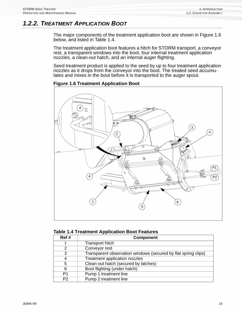
The major components of the treatment application boot are shown in Figure 1.6 below, and listed in Table 1.4.
The treatment application boot features a hitch for STORM transport, a conveyor rest, a transparent windows into the boot, four internal treatment application nozzles, a clean-out hatch, and an internal auger flighting.
Seed treatment product is applied to the seed by up to four treatment application nozzles as it drops from the conveyor into the boot. The treated seed accumu-lates and mixes in the boot before it is transported to the auger spout.
Figure 1.6 Treatment Application Boot
Table 1.4 Treatment Application Boot FeaturesRef # Component
1 Transport hitch2 Conveyor rest3 Transparent observation windows (secured by flat spring clips)4 Treatment application nozzles5 Clean-out hatch (secured by latches)6 Boot flighting (under hatch)
P1 Pump 1 treatment lineP2 Pump 2 treatment line
2
34
15
6
4
4
P2
P1
30946 R0 15

1. INTRODUCTION STORM SEED TREATER
1.2. CONVEYOR ASSEMBLY OPERATION AND MAINTENANCE MANUAL
1.2.3. TREATMENT PUMPS AND CALIBRATION SYSTEM
The major components of the treatment pumps system are shown in Figure 1.7 below, and listed in Table 1.5. See “Calibration System” on page 18 for infor-mation about the calibration system.
The STORM has two treatment pumps (and associated, referred to in the software user interface as Pump 1 and Pump 2 (see Figure 1.7).
Calibration is a required step in creating a new treatment Job, but pumps should be calibrated to the treatment fluid to be applied before each use. Calibration ensures accurate metering of treatment fluid, preventing under- or over-treating of the seed.
Figure 1.7 Treatment Pump System
Table 1.5 Treatment Pump FeaturesRef # Component
1 Pump 12 Pump 23 Pressure gauge, pump 14 Pressure gauge, pump 25 Treatment filter, pump 16 Treatment filter, pump 27 Treatment pump tubing element, pump 18 Treatment pump tubing element, pump 29 Treatment calibration hose
10 Dry-break coupler, pump 1 treatment hose11 Dry-break coupler, pump 2 treatment hose12 Pump 1 treatment line13 Pump 2 treatment line
14Quick connect for combined flow (Pump 1 and Pump 2 out-put) on Pump 1 line when connected to Pump 1 treatment filter.
2
1
3
48
7
65
9
11
10
12
13 14
2
1
16 30946 R0

STORM SEED TREATER 1. INTRODUCTION
OPERATION AND MAINTENANCE MANUAL 1.2. CONVEYOR ASSEMBLY
TREATMENT PUMPS
Treatment pumps use a peristaltic design that moves fluid with rollers that squeeze fluid through the tubes in the desired direction (both pumps are reversible). Each pump is controlled separately by control system software. Each pump draws from its own fluid source.
The pumps are designed to deliver a specific amount of product per revolution, but factors such as tube condition, temperature, and treatment product viscosity can affect the accuracy of pump metering. These factors are compensated for by calibration process performed by the operator.
PRESSURE GAUGES
Each pump has a separate pressure gauge that indicates the pressure in the hose during treating. The gauges are used primarily to indicate when treatment fluid has reached the nozzles (pressure will spike moderately and hold), but a high sustained operating pressure can also provide indication of a filter or nozzle blockage.
TREATMENT FILTERS
Each pump has an separate in-line filter located on the valve assembly. The purpose of the filters is to prevent large particles from reaching and potentially blocking the treatment nozzles.
Disassemble, clean, and reassemble the filters on a weekly basis during regular usage, as well as whenever the treatment product is changed.
PUMP TUBING ELEMENTS
Each pump has a separate tubing element that runs from the valve assembly, through its respective pump, and to its treatment container.
Tubing elements are specifically designed for the application. If a tubing elements needs to be replaced, contact your distributor for the correct part.
Before operating the STORM, always ensure that the tubing elements are correctly installed and in good condition.
TREATMENT APPLICATION NOZZLES
There are two pairs of nozzles on the boot, located on opposite ends of the boot. In the standard configuration (separate pump flows), each nozzle in a pair are supplied treatment fluid by separate pumps. In the optional combined flow configuration, Pump 1 and Pump 2 outputs are combined onto a single nozzle in each pair, supplied by the Pump 1 line.
TREATMENT LINES
Each pump has a treatment line that runs from its associated filter to the nozzles on the boot, and each treatment line splits to supply a nozzle on each side of the boot.
Note: The treatment lines can be configured for combined flow to the Pump 1 line (output of both pumps combined on the Pump 1 line) by disconnecting the Pump 2 line quick-connect from the Pump 2 treatment filter and connecting the short line from the Pump 1 line “T” in its place.
30946 R0 17

1. INTRODUCTION STORM SEED TREATER
1.2. CONVEYOR ASSEMBLY OPERATION AND MAINTENANCE MANUAL
1.2.4. CALIBRATION SYSTEM
The calibration system (see Figure 1.8 below) is made up of:
• two ball valves (1,2) used to select between treating and calibration posi-tions for their respective pumps,
• a third ball-valve (3) that is selectively used during calibration,• a calibration cylinder that is connected to the calibration valve assembly
with a hose.Figure 1.8 Calibration System Features
TO CALIBRATE:
PUMP 2
PUMP 1
2 1
2 1
TO TREAT:TO OPERATE PUMPS 1 & 2:
OPERATING PROCEDURE
Refer to Operator’s Manual for detailedtreating information.
Before operating, check that pump adjustment knob is tightby turning fully clockwise. DO NOT loosen, or metering will not function correctly.
A
ENGAGEDDISENGAGED
A
21905Made in Canada
2 1
3
3 3
18 30946 R0

STORM SEED TREATER 1. INTRODUCTION
OPERATION AND MAINTENANCE MANUAL 1.2. CONVEYOR ASSEMBLY
During calibration, fluid is pumped by the selected pump through the calibration valve assembly, which diverts the fluid from the treatment nozzles to the calibration cylinder, where it is measured by the operator. This measurement is entered into the calibration screen, and the control unit uses the measurement to adjust the calibration for the pump for the specific treatment fluid used.
Before proceeding with calibration via the control unit software, always:
• set the calibration valves to their appropriate position for calibration of the specific pump to be calibrated.
• move the calibration cylinder from the horizontal storage/treatment posi-tion to the vertical calibration position.
Calibration should always be done when a job is first configured as well as before each run is treated.
See “Calibration Procedures” on page 83 for detailed information about calibration.
30946 R0 19

1. INTRODUCTION STORM SEED TREATER
1.2. CONVEYOR ASSEMBLY OPERATION AND MAINTENANCE MANUAL
1.2.5. STORM MOVER ASSEMBLY
The STORM mover assembly is used to:
• move the entire STORM auger short distances to position the unit for receiv-ing seed for treatment,
• raise and lower the conveyor and intake hopper (intake end), • raise and lower the main auger tube (winch).
The mover assembly is hydraulically powered. The gasoline motor must be on with the hydraulic pump engaged before the controls will function.
Ensure that the main wheel over-center handles are in the engaged position before operating (see Figure 1.12).
Important: Always ensure that the latch system for clean out position is latched during clean-out activity.
Figure 1.9 STORM Mover Assembly, Working Position
AUGER DRIVE WHEELS EGRAHCSIDEKATNI
RAISE
LOWER
RAISE
LOWER
FORWARD
REVERSE
STEER
21789Made in Canada
LATCH SYSTEM FOR CLEAN OUT POSITION(UNLATCHED)
PIN IN STORAGE POSITION
20 30946 R0

STORM SEED TREATER 1. INTRODUCTION
OPERATION AND MAINTENANCE MANUAL 1.2. CONVEYOR ASSEMBLY
Figure 1.10 STORM Mover Assembly, Transport Position
30946 R0 21

1. INTRODUCTION STORM SEED TREATER
1.2. CONVEYOR ASSEMBLY OPERATION AND MAINTENANCE MANUAL
Figure 1.11 STORM Mover Assembly, Cleanout Position
22 30946 R0

STORM SEED TREATER 1. INTRODUCTION
OPERATION AND MAINTENANCE MANUAL 1.2. CONVEYOR ASSEMBLY
Figure 1.12 Wheel Over-Center Handle Positions
NOTICE
Ensure that the over-center bolts are tight enough to prevent the handle from disengaging when in use. If they are not tight enough, damage to the gears and motor will result.
30946 R0 23

1. INTRODUCTION STORM SEED TREATER
1.2. CONVEYOR ASSEMBLY OPERATION AND MAINTENANCE MANUAL
24 30946 R0

STORM SEED TREATER 2. SAFETY
OPERATION AND MAINTENANCE MANUAL 2.1. SAFETY ALERT SYMBOL AND SIGNAL WORDS
2. Safety2.1. Safety Alert Symbol and Signal Words
This safety alert symbol indicates important safety messages in this manual. When you see this symbol, be alert to the possibility of injury or death, carefully read the message that follows, and inform other operators.
SIGNAL WORDS: Note the use of the signal words DANGER, WARNING, CAUTION, and NOTICE with the safety messages. The appropriate signal word for each message has been selected using the definitions below as a guideline.
Indicates an imminently hazardous situation that, if not avoided, will result in serious injury or death.
Indicates a hazardous situation that, if not avoided, could result in serious injury or death.
Indicates a hazardous situation that, if not avoided, may result in minor or moderate injury.
Indicates a potentially hazardous situation that, if not avoided, may result in property damage.
2.2. Basic Operator Safety and Qualifications
The safety information found throughout the complete Safety Section of the manual applies to all safety practices. Additional instructions specific to a certain safety practice (such as Operation Safety), can be found in the appropriate section.
YOU are responsible for the SAFE use and maintenance of your equipment. YOU must ensure that you and anyone else who is going to work around the equipment under-stands all procedures and related SAFETY information contained in this manual.
Remember, YOU are the key to safety. Good safety practices not only protect you, but also the people around you. Make these practices a working part of your safety program. All accidents can be avoided.
• It is the equipment owner, operator, and maintenance personnel's respon-sibility to read and understand ALL safety instructions, safety decals, and manuals and follow them when assembling, operating, or maintaining the equipment.
• Equipment owners must give instructions and review the information initially and annually with all personnel before allowing them to operate this product. Untrained users/operators expose themselves and bystanders to possible serious injury or death.
• This equipment is not intended to be used by children.
• Use this equipment for its intended purposes only.
• Do not modify the equipment in any way without written permission from the manu-facturer. Unauthorized modification may impair the function and/or safety, and could affect the life of the equipment. Any unauthorized modification of the equipment will void the warranty.
30946 R0 25

2. SAFETY STORM SEED TREATER
2.3. OVERHEAD POWER LINES OPERATION AND MAINTENANCE MANUAL
2.3. Overhead Power Lines
• When operating or moving, keep equipment away from overhead power lines and devices.
• This equipment is not insulated.
• Electrocution can occur without direct contact.
2.4. Rotating Flighting
• KEEP AWAY from rotating flighting.
• DO NOT remove or modify flighting guards, doors, or covers. Keep in good working order. Have replaced if damaged.
• DO NOT operate the equipment without all guards, doors, and covers in place.
• NEVER touch the flighting. Use a stick or other tool to remove an obstruction or clean out.
• Shut off and lock out power to adjust, service, or clean.
2.5. Cleated Conveyor Belt
• KEEP HANDS AWAY from moving cleated conveyor belt.
• DO NOT remove or modify guards, doors, or covers. Keep in place and in good working order. Have replaced if damaged.
• DO NOT operate the conveyor without all guards, doors, and covers in place.
• Shut off and lock out power to adjust, service, or clean.
2.6. Rotating Parts Safety
• Keep body, hair, and clothing away from rotating pulleys, belts, chains, and sprock-ets.
26 30946 R0

STORM SEED TREATER 2. SAFETY
OPERATION AND MAINTENANCE MANUAL 2.7. WORK AREA SAFETY
• Do not operate with any guard removed or modified. Keep guards in good working order.
• Shut off and remove key or lock out power source before inspecting or servicing machine.
2.7. Work Area Safety
• Have another trained person nearby who can shut down the equipment in case of accident.
• The work area should be kept clear of bystanders.
• Before raising/lowering/moving the equipment, make sure the area around the equipment is clear of obstructions and/or untrained personnel. Never allow anyone to stand on or beneath the equipment when it is being placed.
• Place equipment on reasonably level ground when raising, lower-ing, positioning, or operating.
• Chock wheels after placement.
• Lower equipment at completion of operation or when not in use.
• Keep the work area clean and free of debris.
• Keep out from under equipment and undercarriage area.
30946 R0 27
2. SAFETY STORM SEED TREATER
2.8. SEED TREATER SAFETY OPERATION AND MAINTENANCE MANUAL
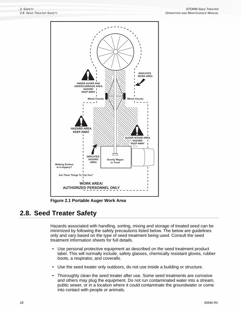
Figure 2.1 Portable Auger Work Area
2.8. Seed Treater Safety
Hazards associated with handling, sorting, mixing and storage of treated seed can be minimized by following the safety precautions listed below. The below are guidelines only and vary based on the type of seed treatment being used. Consult the seed treatment information sheets for full details.
• Use personal protective equipment as described on the seed treatment product label. This will normally include, safety glasses, chemically resistant gloves, rubber boots, a respirator, and coveralls.
• Use the seed treater only outdoors, do not use inside a building or structure.
• Thoroughly clean the seed treater after use. Some seed treatments are corrosive and others may plug the equipment. Do not run contaminated water into a stream, public sewer, or in a location where it could contaminate the groundwater or come into contact with people or animals.
UNDER AUGER ANDUNDERCARRIAGE AREA
HAZARDKEEP AWAY
AUGER INTAKE AREAHAZARD
KEEP AWAY
Wheel Chocks Wheel Chocks
HAZARD AREAKEEP AWAY
WORK AREA!AUTHORIZED PERSONNEL ONLY
Gravity Wagonor Truck
Walking SurfaceIs it slippery?
Are There Things To Trip You?
INDICATES WORK AREA
INDICATES HAZARD
AREA
28 30946 R0

STORM SEED TREATER 2. SAFETY
OPERATION AND MAINTENANCE MANUAL 2.9. EQUIPMENT STABILITY
2.9. EQUIPMENT STABILITY
• Transport and place equipment on reasonably level ground when raising, lowering, positioning, or operating.
• Chock wheels and anchor intake end after placement.
2.10. Guards Safety
Proper guards are important to ensure workers are safe.
• Install guards to prevent workers from contacting moving parts.
• Do not operate equipment unless all guards are in place.
• Do not walk or step on guards.
• Lock out power before removing a guard.
• Ensure all guards are replaced after performing maintenance.
30946 R0 29

2. SAFETY STORM SEED TREATER
2.11. TRANSPORT SAFETY OPERATION AND MAINTENANCE MANUAL
2.11. TRANSPORT SAFETY
• Check with local authorities regarding transport on public roads. Obey all applicable laws and regulations.
• Always travel at a safe speed, never exceeding 20 mph (32 km/h). Reduce speed on rough surfaces. Use caution when turning corners or meeting traffic.
• Make sure the SMV (slow moving vehicle) emblem and all the lights and reflectors that are required by local authorities are in place, are clean, and can be seen by all over-taking and oncoming traffic. Always use hazard-warn-ing flashers on tractor/towing vehicle when transporting unless prohibited by law.
• Do not allow riders on the machine, towing vehicle, tractor, or skid steer during transport.
• Stay away from overhead obstructions and power lines when operating and transporting. Electrocution can occur without direct contact.
• Fully lower equipment before transporting, and only raise when next to storage facility.
• Attach to towing vehicle with a pin and retainer. Always attach safety chain(s).
• Do not raise the intake end above drawbar, upending may occur.
• Do not transport on slopes greater than 20°.
2.12. TOWING THE EQUIPMENT
• Check with local authorities regarding transport on public roads. Obey all applicable laws and regulations.
• Always travel at a safe speed, never exceeding 20 mph (32 km/h). Reduce speed on rough surfaces. Use caution when turning corners or meeting traf-fic.
• Make sure the SMV (slow moving vehicle) emblem and all the lights and reflectors that are required by local authorities are in place, are clean, and can be seen by all over-taking and oncoming traffic. Always use hazard-warn-ing flashers on tractor/towing vehicle when transporting unless prohibited by law.
30 30946 R0

STORM SEED TREATER 2. SAFETY
OPERATION AND MAINTENANCE MANUAL 2.13. CLEANUP AND STORAGE SAFETY
• Do not allow riders on the equipment or towing vehicle during transport.
• Attach to towing vehicle with a pin and retainer. Always attach safety chain(s).
• Do not raise the intake end above drawbar, upending may occur.
• Do not transport on slopes greater than 20°.
2.13. Cleanup and Storage Safety
When operation has been completed:
• Clean entire work area
• Remove anchors, supports, and chocks
• Move auger slowly out of “working” position with towing vehicle - not by hand
• If not in “transport” position, lower auger to the “full down” position immediately upon clearance of any obstructions
• Transport to the new work area or storage area. Observe previous transport and placement instructions.
2.14. HYDRAULIC WINCH
• Keep away from rotating cable drum and winch cable. Do not touch or grab cable while winch is being operated or use hands to guide the cable. Failure to heed could result in serious injury.
• Inspect cable and cable clamps before installing and using hydraulic winch. Replace cable if frayed or damaged. Tighten cable clamps if necessary.
• Do not continue to supply power to hydraulic winch after equipment has reached full up position.
• Do not disconnect hydraulic quick couplers when lines are pressurized.• Make sure lift cable is seated in cable pulley.• Always keep a minimum of 3 cable wraps on the cable drum.
2.15. Battery Safety
• Wear safety glasses when working near batteries.
• Make certain the battery or terminal covers are in place and in good working order.
• Keep all sparks and flames away from batteries; gas given off by electrolyte is explosive.
• Avoid contact with battery electrolyte. Wash off any spilled electrolyte immediately.
• Do not tip batteries more than 45° to avoid electrolyte loss.
• To avoid injury from sparks or short circuits, disconnect battery ground cable before servicing any part of an electrical system.
30946 R0 31

2. SAFETY STORM SEED TREATER
2.16. TIRE SAFETY OPERATION AND MAINTENANCE MANUAL
2.16. Tire Safety
• Inflate tires to the recommended pressure on tire sidewall.
• Tires should not be operated at speeds higher than their rated speed.
• Keep wheel lug nuts tightened to manufacturer’s recommendations.
• Never reinflate a tire that has been run flat or seriously under-inflated without remov-ing the tire from the wheel. Have the tire and wheel closely inspected for damage before remounting.
• DO NOT cut or weld to the tire rim with the tire mounted on the rim. This action may cause an explosion which could result in serious injury or death.
• DO NOT attempt to mount a tire unless you have the proper equipment and experi-ence to do the job.
• Failure to follow proper procedures when mounting a tire on a wheel or rim can produce an explosion that may result in serious injury or death.
• Have a qualified tire dealer or repair service perform required tire maintenance.
• When replacing worn tires, make sure they meet the original tire specifications. Never undersize the replacement tire.
2.17. RAISING AND LOWERING EQUIPMENT
• Before raising/lowering/moving/adjusting the equipment, make sure the area around the equipment is clear of obstructions and/or untrained personnel. Never allow anyone to stand on or beneath the equipment when it is being placed.
• Lower equipment to its lowest position when not in use.• Empty equipment before raising or lowering.• Do not get on or beneath equipment when raising or lowering.• Raise and lower equipment on reasonably level ground only.
2.18. Drives and Lockout Safety
Inspect the power source (drive) before using and know how to shut down in an emergency. Whenever you service or adjust your equipment, make sure you shut down and lock out your power source to prevent inadvertent start-up. Know the procedure(s) that applies to your equipment from the following power sources.
32 30946 R0

STORM SEED TREATER 2. SAFETY
OPERATION AND MAINTENANCE MANUAL 2.18. DRIVES AND LOCKOUT SAFETY
2.18.1. Electric Motor Safety
Power Source
• Electric motors and controls shall be installed and serviced by a qualified electrician and must meet all local codes and standards.
• A magnetic starter should be used to protect your motor.
• You must have a manual reset button.
• Reset and motor starting controls must be located so that the operator has full view of the entire operation.
• Locate main power disconnect switch within reach from ground level to permit ready access in case of an emergency.
• Motor must be properly grounded.
• Guards must be in place and secure.
• Ensure electrical wiring and cords remain in good condition; replace if necessary.
Lockout
• The control box and motor should be unplugged during shutdown or whenever main-tenance is performed.
• If reset is required, disconnect all power before resetting motor.
2.18.2. Gas Engine Safety
Power Source
• Keep guards in place and secure.
• Properly ventilate surrounding area.
• Never fill the fuel tank while smoking or near an open flame. Always shut down and allow engine to cool before filling with fuel.
• Never overfill the tank or spill fuel. If fuel is spilled, clean it up immediately.
• Be sure to use the correct type and grade of fuel.
• Ground the fuel funnel or nozzle against the filler neck to prevent sparks that could ignite fuel vapors.
• Be sure to replace the fuel fill cap when you are done.
R O P E S TA R T
E L E C T R I C S TA R T
30946 R0 33

2. SAFETY STORM SEED TREATER
2.19. PERSONAL PROTECTIVE EQUIPMENT OPERATION AND MAINTENANCE MANUAL
Lockout
• For engines with an electric start, remove the ignition key, the spark plug wire, or the spark plug.
• For engines with a rope or crank start, remove the spark plug wire or the spark plug.
2.18.3. Hydraulic Power Safety
Power Source
• Refer to the rules and regulations applicable to the power source operating your hydraulic drive.
• Do not connect or disconnect hydraulic lines while sys-tem is under pressure.
• Keep all hydraulic lines away from moving parts.
• Escaping hydraulic fluid under pressure will cause serious injury if it penetrates the skin surface (serious infection or toxic reaction can develop). See a doctor immediately if injured.
• Use metal or wood as a backstop when searching for hydraulic leaks and wear proper hand and eye protection.
• Check all hydraulic components are tight and in good condi-tion. Replace any worn, cut, abraded, flattened, or crimped hoses.
• Do not attempt any makeshift repairs to the hydraulic fittings or hoses with tape, clamps, or adhesive. The hydraulic system operates under extremely high pressure; such repairs will fail suddenly and create a hazardous and unsafe condition.
Lockout
• Always place all hydraulic controls in neutral and relieve system pressure before dis-connecting or working on hydraulic system.
2.19. Personal Protective Equipment
Safety Glasses
• Wear safety glasses at all times to protect eyes from debris.
Respirator
• A respirator may be needed to prevent breathing potentially harmful fumes and dust.
34 30946 R0
STORM SEED TREATER 2. SAFETY
OPERATION AND MAINTENANCE MANUAL 2.20. SAFETY DECALS
Coveralls
• Wear coveralls to protect skin.
Chemically Resistant Gloves
• Wear chemically resistant gloves to protect your hands from chemicals.
Rubber Boots
• Wear rubber boots to protect feet.
Steel-Toe Boots
• Wear steel-toe boots to protect feet from falling debris.
2.20. Safety Decals
• Keep safety decals clean and legible at all times.
• Replace safety decals that are missing or have become illegible. See decal location figures that follow.
• Replaced parts must display the same decal(s) as the original part.
• Replacement safety decals are available free of charge from your distributor, dealer, or factory.
2.20.1. Decal Installation/Replacement
1. Decal area must be clean and dry, with a temperature above 50°F (10°C).
2. Decide on the exact position before you remove the backing paper.
3. Align the decal over the specified area and carefully press the small portion with the exposed sticky backing in place.
4. Slowly peel back the remaining paper and carefully smooth the remaining portion of the decal in place.
5. Small air pockets can be pierced with a pin and smoothed out using the sign backing paper.
2.20.2. Safety Decal Locations and Details
Replicas of the safety decals that are attached to the equipment and their messages are shown in the figure(s) that follow. Safe operation of the equipment requires that you familiarize yourself with the various safety decals and the areas or particular functions that the decals apply to, as well as the safety precautions that must be taken to avoid serious injury, death, or damage.
Wheatheart reserves the right to update safety decals without notice. Safety decals may not be exactly as shown.
30946 R0 35

2. SAFETY STORM SEED TREATER
2.21. SAFETY DECAL PLACEMENT OPERATION AND MAINTENANCE MANUAL
2.21. Safety Decal Placement
Figure 2.2 Safety Decal Locations
DANGER
ROTATING FLIGHTING HAZARDTo prevent death or serious injury:
• KEEP AWAY from rotating auger flighting.
• DO NOT remove or modify auger flighting guards, doors, or covers. Keep in good working order. Have replaced if damaged.
• DO NOT operate the auger without all guards, doors, and covers in place.
• NEVER touch the auger flighting. Use a stick or other tool to remove an obstruction or clean out.
• Shut off and lock out power to adjust, service, or clean.
20813Made in Canada
WARNING
To prevent serious injury or death:
• Read and understand the manual before assembling, operating, or maintaining the equipment.
• Only trained personnel may assemble, operate, or maintain the equipment.
• Children and untrained personnel must be kept outside of the work area.
• If the manual, guards, or decals are missing or damaged, contact factory or dealer for replacements.
• Lock out power before performing maintenance.
• To prevent equipment collapse, support equipment tube while disassembling certain components.
• Electric motors must be grounded. Disconnect power before resetting overloads.
Made in Canada 20807
WARNING
ENTANGLEMENT HAZARDTo prevent serious injury or death:
• Keep body, hair, and clothing away from rotating pulleys, belts, chains, and sprockets.
• Do not operate with any guard removed or modified. Keep guards in good working order.
• Shut off and remove key or lock out power source before inspecting or servicing machine.
Made in Canada 20804
WARNINGMISSING GUARD HAZARDTo prevent serious injury or death, shut off power and reattach guard before operating machine.
20803Made in Canada
LOCATED BEHIND GUARD
LOCATED INSIDE
CONTROL BOX20822
20821
20803
20807
20813
20804
WARNINGBELT CRUSH HAZARD
To prevent serious injury:
• KEEP HANDS AWAY from moving cleated conveyor belt.
• DO NOT remove or modify guards, doors, or covers. Keep in place and in good working order. Have replaced if damaged.
• DO NOT operate the conveyor without all guards, doors, and covers in place.
• Shut off and lock out power to adjust, service, or clean
54112adanaC ni edaM
21145
WARNINGCRUSH HAZARD
To prevent serious injury, insert pin before clean out of hopper.
21837Made in Canada
CAUTION
21838 Made in Canada
NOTICE
To prevent damage, lock conveyor in place before transporting. Made in Canada 21908
WARNINGTo prevent serious injury or death:• Keep away from rotating cable drum and winch
cable.• Inspect lift cable periodically; replace if damaged.• Inspect cable clamps periodically; tighten if
necessary. 20810Made in Canada
20810
21838
21837
WARNINGTRANSPORT HAZARD
To prevent serious injury or death:
• Securely attach equipment to vehicle with correct pin and safety chains.
• Use a tow vehicle to move equipment.31171adanaC ni edaM
17113
WARNING AVERTISSEMENTHAZARDOUS VOLTAGE
INSIDETo prevent death or serious injury:• If the control box is not functioning
normally, do not open box; contact your authorized dealer.
• To service box, first disconnect main power supply. Components inside box may contain hazardous voltage even after power has been disconnected.
TENSION DANGEREUSE À L'INTÉRIEUR
Pour éviter les accidents mortels ou les blessures graves:• Si le boîtier de commande ne fonctionne pas correctement,
ne pas l'ouvrir; contactez votre revendeur agréé.• Avant d'ouvrir le boîtier, coupez la source d'alimentation
électrique principale. Les composants internes renferment une tension résiduelle dangereuse, même lorsque l'alimentation a été coupée.
Made in Canada 20821
DANGER DANGERHAZARDOUS VOLTAGE
Can shock, burn, or cause death.Do not work in here unless you are a qualified electrician.
TENSION DANGEREUSERisque d'électrocution, de brûlure ou d'accidents mortels.Ne pas intervenir à moins d'être un électricien qualifié.
Made in Canada 20822
21908
NOTICETo prevent damage, wheels must be free to move when raising or lowering equipment.When equipment is positioned, chock all wheels. Made in Canada 19960
19960
DANGER
ELECTROCUTION HAZARDTo prevent death or serious injury:
• When operating or moving, keep equipment away from overhead power lines and devices.
• Fully lower equipment before moving.
This equipment is not insulated.Electrocution can occur without direct contact. 20817
Made in Canada
20817
36 30946 R0

STORM SEED TREATER 2. SAFETY
OPERATION AND MAINTENANCE MANUAL 2.21. SAFETY DECAL PLACEMENT
Figure 2.3 Other Decal Locations
PUM
P 1
& 2
CO
MB
INED 21
910
Mad
e in
Can
ada
2194
4
2190
7
2191
0
121
906
Mad
e in
Can
ada
2190
6
PUM
P 2 21
913
Mad
e in
Can
ada
PUM
P 2
SUPP
LY 2191
5M
ade
in C
anad
a
2191
5PUM
P 1 21
912
Mad
e in
Can
ada
2191
2
221
907
Mad
e in
Can
ada
2194
4M
ade
in C
anad
a
2191
3
PUM
P 1
SUPP
LY 2191
4M
ade
in C
anad
a
2191
4
PUM
P 1
& 2
SEP
AR
ATE
2191
1M
ade
in C
anad
a
2191
1
AU
GER
DR
IVE
WH
EELS
EG
RA
HCSI
DE
KAT
NI RA
ISE
LOW
ER
RA
ISE
LOW
ER
FOR
WA
RD
REV
ERSE
STEE
R
2178
9M
ade
in C
anad
a
2178
9
FOR
WA
RD
REVER
SE
2190
9M
ade
in C
anad
a
2190
9
TRA
NSP
OR
T LO
CK
.PU
LL U
P B
EFO
RE
LOW
ERIN
G W
HEE
L M
OVE
.21
839
Mad
e in
Can
ada
2183
9
TO C
ALI
BR
ATE
:
PUM
P 2
PUM
P 1 2
1
21
TO T
REA
T:TO
OPE
RA
TE P
UM
PS 1
& 2
:
OP
ER
AT
ING
PR
OC
ED
UR
E
Ref
er to
Ope
rato
r’s
Man
ual f
or d
etai
led
treat
ing
info
rmat
ion.
Bef
ore
oper
atin
g, c
heck
that
pu
mp
adju
stm
ent k
nob
is ti
ght
by tu
rnin
g fu
lly c
lock
wis
e.
DO
NO
T lo
osen
, or m
eter
ing
will
not
func
tion
corr
ectly
.
A
ENG
AG
EDD
ISEN
GA
GED
A
2190
5M
ade
in C
anad
a
21
333
2190
5
30946 R0 37

2. SAFETY STORM SEED TREATER
2.22. SAFETY DECAL CONTENT OPERATION AND MAINTENANCE MANUAL
2.22. Safety Decal Content
Rotating Flighting Hazard
To prevent death or serious injury:
•KEEP AWAY from rotating auger flighting.
•DO NOT remove or modify auger flighting guards, doors, or covers. Keep in good working order. Have replaced if damaged.
•DO NOT operate the auger without all guards, doors, and covers in place.
•NEVER touch the auger flighting. Use a stick or other tool to remove an obstruction or clean out.
•Shut off and lock out power to adjust, service, or clean.
Electrocution Hazard
To prevent death or serious injury:
•When operating or moving, keep equipment away from overhead power lines and devices.
•Fully lower equipment before moving.
This equipment is not insulated.
Electrocution can occur without direct contact.
Hazardous Voltage
Can shock, burn, or cause death.
Do not work in here unless you are a qualified electrician.
DANGER
ROTATING FLIGHTING HAZARDTo prevent death or serious injury:
• KEEP AWAY from rotating auger flighting.
• DO NOT remove or modify auger flighting guards, doors, or covers. Keep in good working order. Have replaced if damaged.
• DO NOT operate the auger without all guards, doors, and covers in place.
• NEVER touch the auger flighting. Use a stick or other tool to remove an obstruction or clean out.
• Shut off and lock out power to adjust, service, or clean.
20813Made in Canada
20813
DANGER
ELECTROCUTION HAZARDTo prevent death or serious injury:
• When operating or moving, keep equipment away from overhead power lines and devices.
• Fully lower equipment before moving.
This equipment is not insulated.Electrocution can occur without direct contact. 20817
Made in Canada
20817
DANGER DANGERHAZARDOUS VOLTAGE
Can shock, burn, or cause death.Do not work in here unless you are a qualified electrician.
TENSION DANGEREUSERisque d'électrocution, de brûlure ou d'accidents mortels.Ne pas intervenir à moins d'être un électricien qualifié.
Made in Canada 20822
20822
38 30946 R0

STORM SEED TREATER 2. SAFETY
OPERATION AND MAINTENANCE MANUAL 2.22. SAFETY DECAL CONTENT
To prevent serious injury or death:
•Read and understand the manual before assem-bling, operating, or maintaining the equipment.
•Only trained personnel may assemble, operate, or maintain the equipment.
•Children and untrained personnel must be kept outside of the work area.
•If the manual, guards, or decals are missing or damaged, contact factory or dealer for replace-ments.
•Lock out power before performing maintenance.
•To prevent equipment collapse, support equip-ment tube while disassembling certain compo-nents.
•Electric motors must be grounded. Disconnect power before resetting overloads.
Transport Hazard
To prevent serious injury or death:
•Securely attach equipment to vehicle with correct pin and safety chains.
•Use a tow vehicle to move equipment.
Missing Guard Hazard
To prevent serious injury or death, shut off power and reattach guard before operating machine.
Entanglement Hazard
To prevent serious injury or death:
•Keep body, hair, and clothing away from rotating pulleys, belts, chains, and sprockets.
•Do not operate with any guard removed or modi-fied. Keep guards in good working order.
•Shut off and remove key or lock out power source before inspecting or servicing machine.
WARNING
To prevent serious injury or death:
• Read and understand the manual before assembling, operating, or maintaining the equipment.
• Only trained personnel may assemble, operate, or maintain the equipment.
• Children and untrained personnel must be kept outside of the work area.
• If the manual, guards, or decals are missing or damaged, contact factory or dealer for replacements.
• Lock out power before performing maintenance.
• To prevent equipment collapse, support equipment tube while disassembling certain components.
• Electric motors must be grounded. Disconnect power before resetting overloads.
Made in Canada 20807
20807
WARNINGTRANSPORT HAZARD
To prevent serious injury or death:
• Securely attach equipment to vehicle with correct pin and safety chains.
• Use a tow vehicle to move equipment.31171adanaC ni edaM
17113
WARNINGMISSING GUARD HAZARDTo prevent serious injury or death, shut off power and reattach guard before operating machine.
20803Made in Canada
20803
WARNING
ENTANGLEMENT HAZARDTo prevent serious injury or death:
• Keep body, hair, and clothing away from rotating pulleys, belts, chains, and sprockets.
• Do not operate with any guard removed or modified. Keep guards in good working order.
• Shut off and remove key or lock out power source before inspecting or servicing machine.
Made in Canada 20804
20804
30946 R0 39

2. SAFETY STORM SEED TREATER
2.22. SAFETY DECAL CONTENT OPERATION AND MAINTENANCE MANUAL
To prevent serious injury or death:
•Keep away from rotating cable drum and winch cable.
•Inspect lift cable periodically; replace if damaged.
•Inspect cable clamps periodically; tighten if nec-essary.
Hazardous Voltage Inside
To prevent serious injury or death:
•If the control box is not functioning normally, do not open box; contact your authorized dealer.
•To service box, first disconnect main power sup-ply. Components inside box may contain hazard-ous voltage even after power has been disconnected.
Belt Crush Hazard
To prevent serious injury or death:
•KEEP HANDS AWAY from moving cleated con-veyor belt.
•DO NOT remove or modify guards, doors, or cov-ers. Keep in place and in good working order. Have replaced if damaged.
•DO NOT operate the conveyor without all guards, doors, and covers in place.
•Shut off and lock out power to adjust, service, or clean.
Crush Hazard
To prevent serious injury, insert pin before clean out of hopper.
Pinch Point Hazard
Keep hands clear.
WARNINGTo prevent serious injury or death:• Keep away from rotating cable drum and winch
cable.• Inspect lift cable periodically; replace if damaged.• Inspect cable clamps periodically; tighten if
necessary. 20810Made in Canada
20810
WARNING AVERTISSEMENTHAZARDOUS VOLTAGE
INSIDETo prevent death or serious injury:• If the control box is not functioning
normally, do not open box; contact your authorized dealer.
• To service box, first disconnect main power supply. Components inside box may contain hazardous voltage even after power has been disconnected.
TENSION DANGEREUSE À L'INTÉRIEUR
Pour éviter les accidents mortels ou les blessures graves:• Si le boîtier de commande ne fonctionne pas correctement,
ne pas l'ouvrir; contactez votre revendeur agréé.• Avant d'ouvrir le boîtier, coupez la source d'alimentation
électrique principale. Les composants internes renferment une tension résiduelle dangereuse, même lorsque l'alimentation a été coupée.
Made in Canada 20821
20821
WARNINGBELT CRUSH HAZARD
To prevent serious injury:
• KEEP HANDS AWAY from moving cleated conveyor belt.
• DO NOT remove or modify guards, doors, or covers. Keep in place and in good working order. Have replaced if damaged.
• DO NOT operate the conveyor without all guards, doors, and covers in place.
• Shut off and lock out power to adjust, service, or clean
54112adanaC ni edaM
21145
WARNINGCRUSH HAZARD
To prevent serious injury, insert pin before clean out of hopper.
21837Made in Canada
21837
CAUTION
21838 Made in Canada
21838
40 30946 R0

STORM SEED TREATER 3. TRANSPORT
OPERATION AND MAINTENANCE MANUAL 3.1. TRANSPORT PROCEDURE
3. TRANSPORT
3.1. TRANSPORT PROCEDURE
Follow all safety precautions when transporting the auger and use a proper towing vehicle.
1. If auger is raised, place in full down position. The roller track shoe should be seated against the upper track stop with slight tension on the lift cable.
Important: The winch must have a minimum of 3 wraps of cable on drum when auger is in transport position.
2. Ensure STORM conveyor is in the transport/storage position with the conveyor latch fully engaged and the pin in place.
3. Fully raise the wheel move assembly by retracting the hydraulic cylinders. Ensure that the transport latch is engaged.
Figure 3.1 Transport Position (Conveyor and Mover Kit)
4. Before transporting, disengage the over-center handle at each wheel (see Figure 1.12 in “STORM Mover Assembly” on page 20).
WARNING Before continuing, ensure you have read and understand the relevant information in the safety section. Safety information is provided to help prevent serious injury, death, or property damage.
30946 R0 41

3. TRANSPORT STORM SEED TREATER
3.1. TRANSPORT PROCEDURE OPERATION AND MAINTENANCE MANUAL
5. Hitch the STORM to the towing vehicle with clevis-to-tongue connection. If there is a mismatch, convert the towing vehicle clevis to a compatible tongue.
6. Place and secure hitch pin through the clevis and tongue. If the towing vehicle has larger pin hole, use the largest pin diameter that will fit through the holes of towing vehicle and the STORM hitch. Ensure the pin will not slip through the larger holes by inserting a heavy-duty large diameter washer on the top and bottom of the pin.
Important: Use a type of hitch pin with a load rating that meets or exceeds the carrying capacity of the towing vehicle.
7. Connect the STORM safety chain securely to the towing vehicle. Leave chain slack enough for angular movement.
8. If the distance from the hitch pin to the front or rear chain attachment point is more than 9 inches, attach an intermediate chain support.
Important: Choose a safety chain rated with minimum strength at least equal to the gross weight of the STORM unit being towed. Ensure the safety chain is not worn out, stretched or kinked.
WARNING
For proper and safe transport, DO NOT hitch towing vehicle and auger with clevis-to-clevis connection since this type of connection will limit angular movement and will put extremely high load on the pin which can lead to mechanical failure.
WARNING
To prevent accidental break away of the auger that could result to death and serious injury or implement damage, DO NOT tow the STORM without securing the hitch pin and without a properly sized and undamaged safety chain.
WARNING
If auger wheels are partially or fully buried in snow or grain, failure to clear area around the wheels before moving may cause damage to the auger or result in serious injury.
42 30946 R0

STORM SEED TREATER 3. TRANSPORT
OPERATION AND MAINTENANCE MANUAL 3.1. TRANSPORT PROCEDURE
9. Place belt(s) under tension for transport.
10. Refer to “Transport Safety” on page 30 and “Towing the Equipment” on page 30 for important safety information before towing.
WARNING
Beware of overhead colour obstructions and electrical wires and devices. The STORM models have minimum clearances from 10’–13’ (3.05 m–3.96 m) in normal transport position.
30946 R0 43

3. TRANSPORT STORM SEED TREATER
3.1. TRANSPORT PROCEDURE OPERATION AND MAINTENANCE MANUAL
44 30946 R0
STORM SEED TREATER 4. PLACEMENT
OPERATION AND MAINTENANCE MANUAL
4. PLACEMENT
PRE-OPERATION CHECKLIST
• Be sure there is enough clearance from overhead obstructions, power lines, or other equipment to move the machine into its working position.
• Service the machine per the schedule outlined in the Maintenance section.• Check hydraulic system oil level.• Ensure that all hydraulic lines are free from damage, and that all fittings are
tight.• Visually inspect the unit for damage to components. Replace or repair any
damaged or questionable parts.• Check work site. Clean up working area to prevent slipping or tripping.
When using the STORM for the first time, some air may still be trapped in the hy-draulic system; slowly activate all hydraulic control valves to ensure that all the air is out of the system.
Operators must observe safety procedures at all times and follow the pre-opera-tional checklist before each start-up.
WARNING Before continuing, ensure you have read and understand the relevant information in the safety section. Safety information is provided to help prevent serious injury, death, or property damage.
WARNING
Shut off and remove key or lock out power source before inspecting or servicing the machine.
30946 R0 45
4. PLACEMENT STORM SEED TREATER
4.1. PLACEMENT PROCEDURE OPERATION AND MAINTENANCE MANUAL
4.1. PLACEMENT PROCEDURE
Follow this procedure when placing the machine into its working position:
1. Ensure that the conveyor unit is rotated to working position.2. With the engine at idle, use the hydraulic controls to fully lower the auger tube
before moving the auger into position. 3. Raise the auger intake end off the ground using the hydraulic controls.4. Ensure that the wheel over-center handles are engaged (see Figure 1.12 in
“STORM Mover Assembly” on page 20).5. Move the STORM intake hopper into place by moving the wheel move
control forward or backward to control the direction of travel. Steering is accomplished by turning the handle bar in the desired direction. Steering is easier if the auger is in motion. When positioning the STORM intake hopper:a. Ensure that the STORM conveyor intake is centered between the hopper
bin vertical legs so operator has adequate clearance for operation.
b. Ensure that the STORM unit is positioned to receive the seed to be treated directly into the center of the STORM hopper’s intake grate.
6. Raise the auger spout until it is correctly positioned for transfer of the treated seed into the intended container (e.g. truck container).
7. Raise the STORM conveyor intake and pull the STORM intake hopper up into a fully extended position under the hopper bin slide gate. Properly positioned, the bin or truck hopper slide gate will be slightly lower than the top of the STORM intake hopper, and the STORM conveyor assembly will rest fully on the boot conveyor rest.
8. Use the attached straps to tie the hopper in position by looping the adjustable straps around the hopper bin support tubes or any other bin parts.
Important: Failure to secure straps may cause a substantial amount of seed to leak. Loose straps will cause poor metering
9. Ensure that the STORM control unit is plugged in and initialized.10. Ensure that the conveyor is off, and flood the canvas hopper by opening the
hopper bin slide-gate until the hopper is fully flooded with seed. The hopper bin slide-gate should be open sufficient to ensure hopper is completely flooded at maximum intended operation.
46 30946 R0

STORM SEED TREATER 4. PLACEMENT
OPERATION AND MAINTENANCE MANUAL 4.1. PLACEMENT PROCEDURE
Note: If the intake hopper is under-filled, metering will be inaccurate.
Figure 4.1 STORM Unit Positioned for Seed Treatment
11. Ensure that the STORM is on reasonably level ground when raising, lowering, or positioning.
.
12. Once the STORM is in position, chock wheels on both sides to prevent movement during operation.
13. If required, anchor and/or support the STORM during operation.
CAUTION
Do not attempt to move the auger on uneven or hilly terrain. The mover will not perform well under these conditions and could damage the machine or injure the operator.
WARNING
Never attempt to increase height of auger by positioning wheels on lumber, blocks, or by any other means. To do so will result in damage to equipment and/or personal injury.
Hopper slide gateSeed
Intake hopper(securely strapped to hopper bottom)
Hopper bottom cone
Boot conveyorrest
30946 R0 47

4. PLACEMENT STORM SEED TREATER
4.1. PLACEMENT PROCEDURE OPERATION AND MAINTENANCE MANUAL
WARNING
Do not use auger as a hoist to raise any object regardless of weight. This will create an unsafe condition and will void warranty.
48 30946 R0

STORM SEED TREATER 5. OPERATION
OPERATION AND MAINTENANCE MANUAL 5.1. AUGER DRIVE & LOCKOUT
5. OPERATION
5.1. AUGER DRIVE & LOCKOUT
Correct operation of the STORM requires pre-inspection of the drive system, operator knowledge on how to shut down the system, and a general monitoring of the system during operation.
5.1.1. GAS ENGINE
DRIVE SYSTEM INSPECTION
Before starting the motor, ensure that:
1. The gas tank is properly closed.2. The engine clutch is disengaged.3. The hydraulic pump is disengaged.4. The area surrounding the auger is properly ventilated.5. Pulley shields are in place and secure.
LOCKOUT
1. Shut off the engine.2. Remove the ignition key, the spark plug wire, or the spark plug.
5.1.2. STORM CONVEYOR DRIVE SYSTEM
CONVEYER DRIVE SYSTEM INSPECTION
Before starting the STORM conveyor electric motor, ensure that:
1. The STORM conveyor unit is in working position.2. All inspection hatches are closed.3. The intake hopper is clear of all obstructions except seed to be treated.4. Chain shields are in place and secure.
LOCKOUT
1. Unplug the control box from the power source.2. Tag the control box plug to indicate that it is in a lockout state.
WARNING Before continuing, ensure you have read and understand the relevant information in the safety section. Safety information is provided to help prevent serious injury, death, or property damage.
30946 R0 49
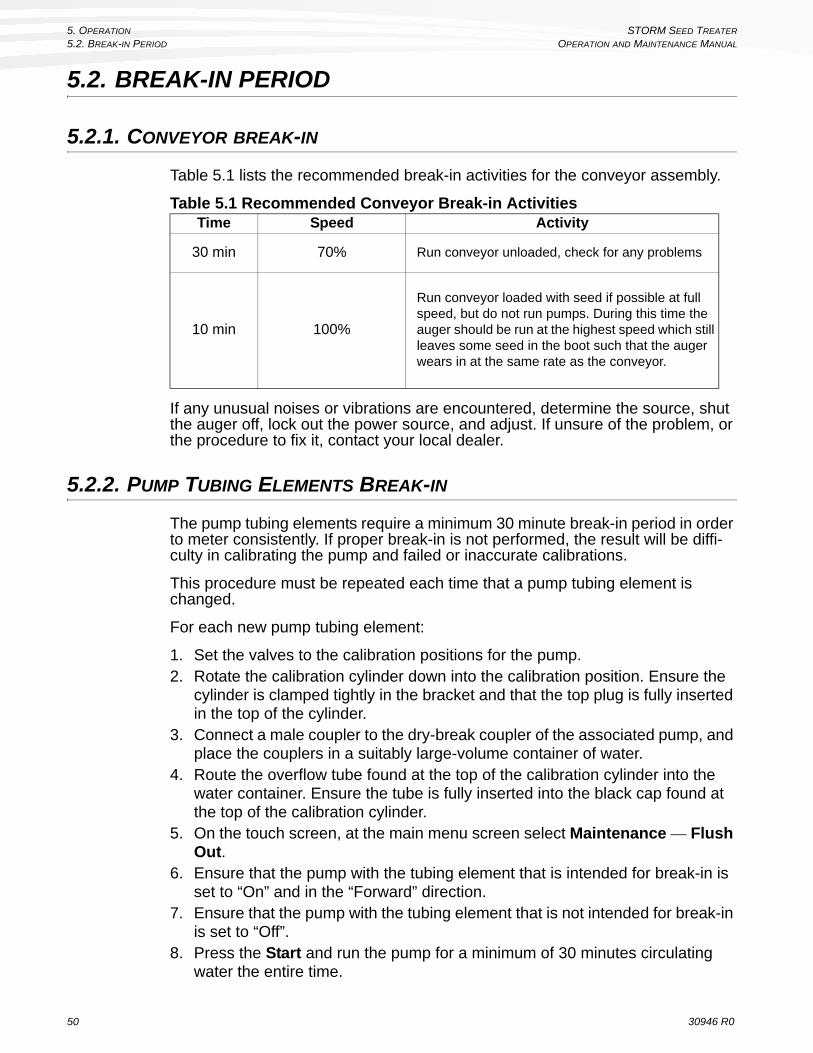
5. OPERATION STORM SEED TREATER
5.2. BREAK-IN PERIOD OPERATION AND MAINTENANCE MANUAL
5.2. BREAK-IN PERIOD
5.2.1. CONVEYOR BREAK-IN
Table 5.1 lists the recommended break-in activities for the conveyor assembly.
Table 5.1 Recommended Conveyor Break-in Activities
If any unusual noises or vibrations are encountered, determine the source, shut the auger off, lock out the power source, and adjust. If unsure of the problem, or the procedure to fix it, contact your local dealer.
5.2.2. PUMP TUBING ELEMENTS BREAK-IN
The pump tubing elements require a minimum 30 minute break-in period in order to meter consistently. If proper break-in is not performed, the result will be diffi-culty in calibrating the pump and failed or inaccurate calibrations.
This procedure must be repeated each time that a pump tubing element is changed.
For each new pump tubing element:
1. Set the valves to the calibration positions for the pump.2. Rotate the calibration cylinder down into the calibration position. Ensure the
cylinder is clamped tightly in the bracket and that the top plug is fully inserted in the top of the cylinder.
3. Connect a male coupler to the dry-break coupler of the associated pump, and place the couplers in a suitably large-volume container of water.
4. Route the overflow tube found at the top of the calibration cylinder into the water container. Ensure the tube is fully inserted into the black cap found at the top of the calibration cylinder.
5. On the touch screen, at the main menu screen select Maintenance — Flush Out.
6. Ensure that the pump with the tubing element that is intended for break-in is set to “On” and in the “Forward” direction.
7. Ensure that the pump with the tubing element that is not intended for break-in is set to “Off”.
8. Press the Start and run the pump for a minimum of 30 minutes circulating water the entire time.
Time Speed Activity
30 min 70% Run conveyor unloaded, check for any problems
10 min 100%
Run conveyor loaded with seed if possible at full speed, but do not run pumps. During this time the auger should be run at the highest speed which still leaves some seed in the boot such that the auger wears in at the same rate as the conveyor.
50 30946 R0

STORM SEED TREATER 5. OPERATION
OPERATION AND MAINTENANCE MANUAL 5.3. PRE-OPERATIONAL CHECKS (FIRST 1000 BU)
5.3. PRE-OPERATIONAL CHECKS (FIRST 1000 BU)
Following the following pre-operational checklist during the first 1000 bu of operation can add to the reliability and life of your machine.
PRE-OPERATIONAL CHECKLIST:
• Read the power source operation manual.• Inspect motor mounting bolts for tightness.• Check oil level in the gear box by removing the filler plug. Make sure the
gear box is half full (center cross shaft) and free of foreign objects.• Inspect all belts for alignment, tightness, and abnormal wear. Adjust or
replace as required.• Inspect components for damage and abnormal wear. Replace as
required.• Check that safety decals are installed and legible. Apply new decals if
required. • Check the wheel bolt torque prior to transporting the unit. See “Bolt
Torque Values” on page 124 for recommended torque values.• Check that tires are inflated to the manufacturer’s recommended pressure
prior to transporting the unit.• Check the upper chain drive tension and alignment.
Please refer to the regular maintenance schedule given in “STORM Maintenance Schedule” on page 99 for recommended service intervals after the break-in period.
30946 R0 51

5. OPERATION STORM SEED TREATER
5.4. STANDARD PRE-OPERATION CHECKS OPERATION AND MAINTENANCE MANUAL
5.4. STANDARD PRE-OPERATION CHECKS
The following items should be checked before operating the machine each time:
• Visually inspect the machine, check engine oil, and service the PTO drive-line (if applicable).
• Check that the gasoline engine gas cap is in place.• Ensure that all guards are in place, and secure.• Check that drive belts are not frayed or damaged, and that they are prop-
erly adjusted and aligned.• Ensure auger wheels are chocked.• See that the discharge spout and intake area are free of obstructions.• Ensure that operators are aware of safety precautions.
5.5. CONTROLS
The STORM Auger section has the following mechanical controls:
• engine throttle: variable RPM• hydraulic pump: engaged/disengaged• auger flighting (clutch switch): on/off• auger flighting (forward/reverse)• auger wheel move: moves and steers the entire STORM auger, raises
and lowers the auger tube (see “STORM Mover Assembly” on page 20).• pause button• calibration valves
In addition to physical controls, the STORM is also has a touch-screen interface that is used to:
• configure, calibrate, and run jobs• view job information and system status• prepare pumps and conveyor for treating• control pumps and conveyor for clean up
52 30946 R0

STORM SEED TREATER 5. OPERATION
OPERATION AND MAINTENANCE MANUAL 5.6. START-UP
5.6. START-UP
5.6.1. GAS ENGINE AND AUGER STARTUP AND SHUTDOWN
NORMAL START-UP
1. Ensure that the hydraulic pump is disengaged.2. Ensure that the auger direction is set to forward.3. Start the engine and then engage the belt engaging lever with engine at idle.
4. Increase the engine speed to achieve the desired augering speed.5. If everything is operating normally, begin seed treatment.
RESTARTING WITH A FULL TUBE
The tube may be filled with material if the machine is shut down inadvertently or for an emergency. It is recommended that you restart with the following procedure:
NOTICE
Foreign objects can cause damage. Remove any obstructions from the intake and discharge areas before operating the unit.
NOTICE
Engine must be idling before belts are engaged.
Engaging belts at high engine speed will result in premature belt wear.
DANGER
Rotating Flight Hazard: Keep away from auger intake.
NOTICE
Auger speed should be proportional to treating rate. Use full throttle only when treating seed at maximum feed rate of 100% and 1/3 throttle when treating at 50%.
NOTICE
Always engage belts with engine idling. Engaging belts at high engine speed will result in premature belt wear
30946 R0 53

5. OPERATION STORM SEED TREATER
5.6. START-UP OPERATION AND MAINTENANCE MANUAL
1. With the power source locked out, remove as much of the seed as possible from the tube and intake.
2. Start the engine and run it at half speed. Slowly engage the belt until the auger is brought up to speed.
3. Once the auger has been started, increase the engine speed to achieve the desired augering speed.
NORMAL SHUTDOWN
1. Near the end of the load, reduce the feed of seed and decrease the auger speed (if possible).
2. Run the auger until the tube is empty.3. When auger is clear of seed, disengage the belt, and stop engine/motor, or
disengage the PTO.4. Shut down, and lock out power source.
EMERGENCY STOP
Although it is recommended that the machine be emptied before stopping, in an emergency situation:
1. Stop or shut down the power source immediately.2. Stop the flow of seed into the STORM intake hopper.
3. Lock out power, and respond to the emergency before resuming work.
NOTICE
Prolonged operation of an empty auger will cause unnecessary wear.
WARNING
The pause button will stop the conveyor and pumps, but the power source should also be disconnected in the event of an emergency stop.
WARNING
Lock out all power before attempting repairs / removing obstructions.
54 30946 R0

STORM SEED TREATER 5. OPERATION
OPERATION AND MAINTENANCE MANUAL 5.6. START-UP
5.6.2. STORM UNIT STARTUP
1. Ensure that the STORM conveyor assembly is rotated into the working position.
2. Connect the Control Box to a dedicated 120 VAC 15 A outlet that has a proper ground connection.
3. Check the touchscreen, and ensure that the control system initializes fully. When fully initialized, the startup screen appears (see Figure 5.1).
4. Software updates are posted to the STORM website. It is recommended that you register at the web address shown in the startup screen as soon as possible so that you will be alerted to software updates and have access to important information about your STORM seed treater.
Figure 5.1 Start-up Screen
5. Press Continue to proceed to the main menu.
NOTICE
If a generator is used to provide power to the STORM, it must be able to provide 120 VAC at least 1750 Watts to the plug servicing the STORM (equivalent to 120 VAC@15A).
NOTICE
Do not use a GFIC-protected socket.
NOTICE
Low supply voltage may result in a tripped circuit breaker. Use a 12 gauge or heavier extension cord (100' maximum length) to help ensure adequate supply voltage.
Continue
For the latest software, register atwww.stormtreaters.com/owners
or contact AGI at 1-855-662-6689
30946 R0 55

5. OPERATION STORM SEED TREATER
5.7. ELECTRONIC CONTROLS OPERATION AND MAINTENANCE MANUAL
5.7. ELECTRONIC CONTROLS
Note: This manual provides support for STORM system software with the application date 30/03/2015. Updated documentation will be available for future software versions as required.
The STORM treatment application is controlled through the STORM system software. The operator uses a touch-screen interface to configure and control seed treatment options and activities.
Operation of STORM treatment application components is discussed in the appropriate sections that follow, as part of specific operating procedures.
The touch screen must be operated using bare fingers to select graphical “buttons” or enter text in configurable fields.
Figure 5.2 below shows the STORM main menu, which shows the selectable graphical buttons for the four main control sub menus:
• Jobs• Maintenance• Alarms• Setup• Transfer & Mix
Note: Transfer & Mix functionality requires the Transfer Kit, available through your dealer.
Figure 5.2 STORM Touch Screen Main Menu 2015
Jobs
Alarms
Maintenance
Transfer & Mix
Set-up
56 30946 R0

STORM SEED TREATER 5. OPERATION
OPERATION AND MAINTENANCE MANUAL 5.7. ELECTRONIC CONTROLS
5.7.1. TOUCHSCREEN CONVENTIONS
In all procedures in this manual, selectable buttons are shown within other instructions as bold text, as seen in the following example:
“To view all currently configured jobs, select Jobs from the main menu.”
More complicated configuration are sometimes compressed into a line of instruction that uses chevrons around italic text (<job>) to indicate when multiple choices are available. When this convention is used, the options are generally clear based on the context, or are explained in a following note, as shown in the example below:
To delete an existing Job:
Jobs —<job> — Delete Job — <Yes or Cancel>
where: job is one of 12 possible Jobs configured in the system.
Table 5.2 Command Button Actions
Command Button
Description
Takes you back one screen or to the last pertinent screen.Won’t save changes to any entry made on the page.Bottom left-hand side of the screenSaves changes to values on the screen and then pro-ceeds to the next screen.Bottom right-hand side of the screen.Acknowledges message and then moves to the next screen.Bottom Right hand side of the screen.
Completes a task.Bottom right-hand side of the screen.
Indicates that there are further choices, similar to Continue.Bottom right-hand side of the screen.
30946 R0 57

5. OPERATION STORM SEED TREATER
5.8. STORM OPERATING PROCEDURES OPERATION AND MAINTENANCE MANUAL
5.8. STORM OPERATING PROCEDURES
The following common procedures are used at various intervals during operation, according to the needs of the operator.
Table 5.3 Category Procedures
System setup
“View and Configure Current Date and Time” on page 59“View Software Version” on page 60“View and Configure Pump Setup” on page 61“View and Configure Advanced Pump Setup” on page 62“View and Configure Conveyor Options” on page 63
Jobs“Creating a New Job” on page 64
“Copy an Existing Job” on page 70“Viewing Configured Jobs” on page 70“Deleting a Job” on page 71“Viewing Job Parameters” on page 71“Viewing Total Amounts of Seed Treated (Job Specific)” on page 72“Viewing Total Amounts of Treatment Used (Job Specific)” on page 73“Viewing Treating History (All Jobs)” on page 74“Viewing Treating History (Specific Job)” on page 75
Treating and calibration
“Seed Treatment” on page 76“Calibration Procedures” on page 83“Cleanup” on page 91
Pump and con-veyor controls
“Flush Out” on page 93“Transfer and Mix” on page 93
Diagnostics“View Lifetime Total Use” on page 94“View Diagnostics” on page 95“Alarms” on page 96
58 30946 R0

STORM SEED TREATER 5. OPERATION
OPERATION AND MAINTENANCE MANUAL 5.9. SYSTEM SETUP
5.9. SYSTEM SETUP
5.9.1. VIEW AND CONFIGURE CURRENT DATE AND TIME
Note: Date and time persist in the STORM control unit memory after power is removed from the system, and generally does not need to be adjusted, with the exception of correcting for time zones and local daylight savings.
From the main menu, select:
Setup — Set Date And Time
• Set the date and time using the touch screen.• Select Save Changes to save the new settings and return to the Setup
menu.• Select Back to abandon any changes and return to the Setup menu.
Figure 5.3 Set Date and Time
Save Changes
To set the Date and Time, simply touch the appropriate box.
The Hour uses a 24 hour clock.
Back
SecondsMinute
12 12 12
mm/dd/yyyy 24:00:00
Month YearDay
Date Time
12 12 12
Hour
30946 R0 59

5. OPERATION STORM SEED TREATER
5.9. SYSTEM SETUP OPERATION AND MAINTENANCE MANUAL
5.9.2. VIEW SOFTWARE VERSION
From the main menu, select:
Setup — Software Version
• Select Back to return to the Setup menu.Figure 5.4 View Software Version
Table 5.4 View Software VersionItem Description
Run time versionThe release number of the operating system that runs the STORM application software.
Application dateThe release date of the currently loaded STORM application software.
Application build timeThe time of day that the current application software was compiled for release.
Run Time Version
Application Date AaBbCcDdEeFfGgHhIiJ
Back
AaBbCcDdEeFfGgHhIiJ
AaBbCcDdEeFfGgHhIiJ
ApplicationBuild Time
60 30946 R0

STORM SEED TREATER 5. OPERATION
OPERATION AND MAINTENANCE MANUAL 5.9. SYSTEM SETUP
5.9.3. VIEW AND CONFIGURE PUMP SETUP
Pump setup informs the system about what pumps and pump tubing elements are in use, which allows the system to accurately warn the operator when a job is not compatible with the current pump/tubing setup.
A default configuration is pre-programmed with factory settings that are typical for STORM general use. Always update pump setup to reflect actual pump configuration for the job every time the STORM is powered up to perform seed treating.
From the main menu, select:
Setup — Pump 1 Setup or Pump 2 Setup
• Select the pump head type and tubing element type to reflect the physical setup of the STORM system, according to the requirements for the treatment to be applied.
• Select Back to abandon any changes and return to the Setup menu.• Select Save and Continue to save changes and return to the Setup menu.• Select Advanced to view or make changes to advanced pump setup param-
eters under the guidance of AGI service staff.Figure 5.5 Pump Setup (Pump 1 and Pump 2)
Table 5.5 Pump Setup Screen FieldsItems Description
Pump Head TypePump type for the motor/pump position as I/P or L/S (setting applies to all pump heads on the motor).
Motor Indicates the motor/pump position: #1 or #2 (pump 1 or pump 2)
Position
Indicates the ganged pump position: 1A, 1B, 1C (for pump 1) or 2A, 2B, 2C (for pump 2). “A” indicates the inner pump head, “B” the middle pump head, and “C” the outer pump head.
The pump tubing element type for each pump position is displayed as one of the following: L/S 15, L/S 24, L/S 35, I/P 26, I/P 73, or NONE. Each tubing element type must match the pump it is used on. NONE indicates that the pump head is not used (and may not actually be installed).
Pump 1Pump Head Type:
Back
I/P
Advanced
I/P
NoneI/P 73
Back
Pump Head Type:
Position
2A
Posit ion
2B
I/P 73
NoneMotor #2
Advanced
Pump 2
NoneMotor #1
P osit ion
1A
Position
1B
Posit ion
1C
Posi tion
2C
None
Save and Continue
Save and Continue
30946 R0 61

5. OPERATION STORM SEED TREATER
5.9. SYSTEM SETUP OPERATION AND MAINTENANCE MANUAL
5.9.4. VIEW AND CONFIGURE ADVANCED PUMP SETUP
Important: Do not adjust any advanced pump parameters unless directed to do so by an AGI service professional.
From the main menu, select:
Setup — Pump 1 Setup or Pump 2 Setup — Advanced
• Select and change the low- and high-speed limits according to the direction of an AGI service professional.
• Select Back to abandon any changes and return to the Setup menu.• Select Save and Continue to save changes and return to the Setup menu.
Figure 5.6 Advanced Pump Setup
<Default is 60 RPM>
330 RPM <Default is 330 RPM>
Pump 1 Low Speed LimitPump 1 High Speed Limit
IMPORTANT
Save and Continue
Back
Advanced pump parameters should not be adjusted from the defaults unless guided by an
AGI Service Profess ional.
60 RPM
62 30946 R0
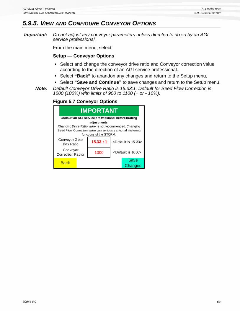
STORM SEED TREATER 5. OPERATION
OPERATION AND MAINTENANCE MANUAL 5.9. SYSTEM SETUP
5.9.5. VIEW AND CONFIGURE CONVEYOR OPTIONS
Important: Do not adjust any conveyor parameters unless directed to do so by an AGI service professional.
From the main menu, select:
Setup — Conveyor Options
• Select and change the conveyor drive ratio and Conveyor correction value according to the direction of an AGI service professional.
• Select “Back” to abandon any changes and return to the Setup menu.• Select “Save and Continue” to save changes and return to the Setup menu.
Note: Default Conveyor Drive Ratio is 15.33:1. Default for Seed Flow Correction is 1000 (100%) with limits of 900 to 1100 (+ or - 10%).
Figure 5.7 Conveyor Options
IMPORTANT
BackSave
Changes
1000
15.33 : 1Conveyor Gear
Box Ratio
Conveyor Correction Factor
<Default is 15.33>
<Default is 1000>
Consult an AGI service proffessional before making
adjustments.Changing Dr ive Ratio value is not recommended. Changing Seed Flow Correction value can seriously affect all metering
functions of the STORM.
30946 R0 63
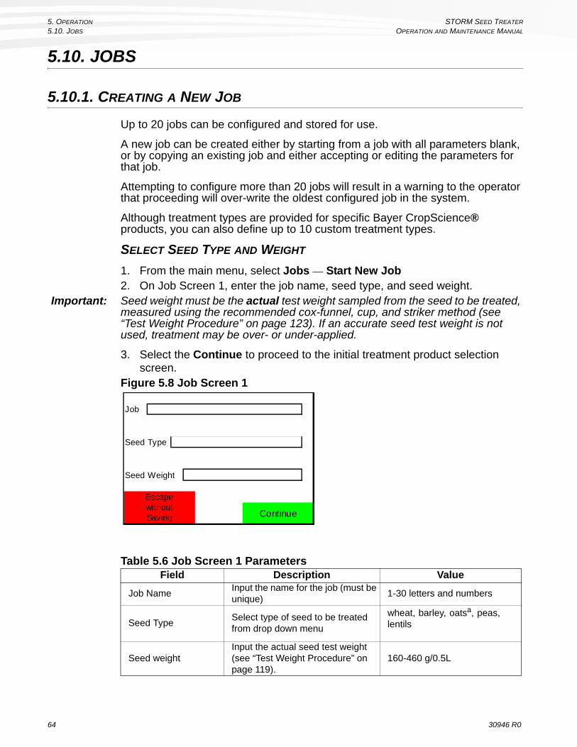
5. OPERATION STORM SEED TREATER
5.10. JOBS OPERATION AND MAINTENANCE MANUAL
5.10. JOBS
5.10.1. CREATING A NEW JOB
Up to 20 jobs can be configured and stored for use.
A new job can be created either by starting from a job with all parameters blank, or by copying an existing job and either accepting or editing the parameters for that job.
Attempting to configure more than 20 jobs will result in a warning to the operator that proceeding will over-write the oldest configured job in the system.
Although treatment types are provided for specific Bayer CropScience® products, you can also define up to 10 custom treatment types.
SELECT SEED TYPE AND WEIGHT
1. From the main menu, select Jobs — Start New Job2. On Job Screen 1, enter the job name, seed type, and seed weight.
Important: Seed weight must be the actual test weight sampled from the seed to be treated, measured using the recommended cox-funnel, cup, and striker method (see “Test Weight Procedure” on page 123). If an accurate seed test weight is not used, treatment may be over- or under-applied.
3. Select the Continue to proceed to the initial treatment product selection screen.
Figure 5.8 Job Screen 1
Table 5.6 Job Screen 1 ParametersField Description Value
Job NameInput the name for the job (must be unique)
1-30 letters and numbers
Seed TypeSelect type of seed to be treated from drop down menu
wheat, barley, oatsa, peas, lentils
Seed weightInput the actual seed test weight (see “Test Weight Procedure” on page 119).
160-460 g/0.5L
Job
Seed Type
Seed Weight
Continue
EscapewithoutSaving
64 30946 R0

STORM SEED TREATER 5. OPERATION
OPERATION AND MAINTENANCE MANUAL 5.10. JOBS
SELECT TREATMENT(S)
The system will allow up to two treatment products to be used for a job (including water).
The products are selected as products A and B, and are assigned to specific pumps by the system only after product selection is confirmed by pressing Continue.
1. Tap on the space next to the “Product A” or “Product B” fields to display the treatment menu.
2. Set the treatment type as either:a. Bayer CropScience® treatments: a treatment from the available options
(see Figure 5.10), or:
b. Custom treatments: select More to view and select one of the 10 custom treatment slots that can be defined by the operator (see Figure 5.11). For the selected custom treatment slot:
• enter a treatment name, the treatment label rate, and any dilution amount that will be used (see Figure 5.11). The application rate is calculated by the system.
• select “Save and Continue” to return to the Job screen.
Figure 5.9 Treatment Product Selection
a. If you have select Oats as your seed type, the conveyor will operate at a fixed speed of 80%. To provide further accuracy of metering, it is recommended to run a batch of 1,000 lbs of seed or more and enter the actual weight of seed at the prompt.
Table 5.7 Treatment Product SelectionItem Description
Product (A or B) Select to choose treatment product.
Application rateSelect to enter an application rate for the product (10-1000 ml/100 kg).
0 ml/100kg
Product A
Application Rate
Application Rate
NONE
0 ml/100kg
Back Help Continue
NONEProduct B
30946 R0 65

5. OPERATION STORM SEED TREATER
5.10. JOBS OPERATION AND MAINTENANCE MANUAL
Figure 5.10 Bayer CropScience® Treatment Options
Figure 5.11 Custom Treatment Options
Table 5.8 Bayer CropScience® Treatment Product SelectionProduct Brand
Product Name and Dilution Label RateApplication
Rate
Raxil
Raxil Pro 325 ml/100kg 325 ml/100kgRaxil Pro Shield 375 ml/100kg 375 ml/100kgRaxil MD plus Stress Shield 480 363 ml/100kg 363 ml/100kgRaxil MD plus Stress Shield 600 350 ml/100kg 350 ml/100kg
Trilex
Trilex AL 370 ml/100kg 370 ml/100kgTrilex EverGol, Diluted 100% 41 ml/100kg 82 ml/100kgTrilex EverGol, Diluted 600% 41 ml/100kg 287 ml/100kgTrilex EverGol, Diluted 500% 41 ml/100kg 246 ml/100kgTrilex EverGol, Diluted 700% 41 ml/100kg 328 ml/100kg
Stress Shield
Stress Shield 600, Cereals, Diluted 100% 50 ml/100kg 100 ml/100kgStress Shield 480, Cereals, Diluted 100% 63 ml/100kg 126 ml/100kgStress Shield 600 (Low rate), Pulses, Diluted 100%
104 ml/100kg 208 ml/100kg
Stress Shield 600 (High rate), Pulses, Diluted 100%
208 ml/100kg 416 ml/100kg
MoreBack
SHIELD
Options Screen 1 Options Screen 2
MoreBack
Water
Other 1
Other 3
None
Other 2
Other 4
Other 8
Other 10Other 9
Other 7
Back
Other 5 Other 6
66 30946 R0

STORM SEED TREATER 5. OPERATION
OPERATION AND MAINTENANCE MANUAL 5.10. JOBS
Figure 5.12 Custom Treatment Parameters
3. After the treatments are selected, the screen will show the configured treatments and their application rates (see Figure 5.13).
Figure 5.13 Job Screen, Application Rates
4. Select Continue to proceed to view pump assignment and calibrate the pumps.
Table 5.9 Custom Treatment ParametersField Description Range
Treatment NameThe operator-defined name for the treat-ment
1-28 characters
Label RateThe application rate for the treatment, as recommended by the manufacturer.
10-1000 ml/100kg
Dilution Amount The percentage of water after dilution 0-1000%
Application RateThe application rate applied by the system after correction for dilution amount
Calculated by the system based on label rate and dilution (ml/100kg)
ApplicationRate
XXXX ml/100kg
TreatmentName
AaBbCcDdEeFfGgHhIiJjKkLlMmNn
Label Rate XXXX ml/100kg
DilutionAmount
XXX %
BackSave and Continue
Help
Product B
Application Rate
AaBbCcDdEeFfGgHhIiJjKkLlMmNn
325 ml/100kg
Back Help Continue
AaBbCcDdEeFfGgHhIiJjKkLlMmNn
325 ml/100kg
Product A
Application Rate
30946 R0 67

5. OPERATION STORM SEED TREATER
5.10. JOBS OPERATION AND MAINTENANCE MANUAL
VIEW PUMP ASSIGNMENT AND PERFORM CALIBRATION
After treatment products are selected, the system assigns the treatment product with the highest application rate to the pump with the highest flow capabilities (if a difference in flow capabilities exists). Similarly, the treatment product with the lowest application rate is assigned to the pump with the lowest flow capabilities.
If both pumps have the same flow capabilities (the same pump, and the same tubing elements), Product A is assigned to Pump 1 and Product B is assigned to Pump 2.
The system also determines the treating speed range based on the capabilities of the pumps, under the assumption that the pump can predictably meter the selected product. The range is subject to change after calibration, when the system determines limits based on actual ability to meter the treatment products.
The status message “Invalid” appears if the treating speed cannot be accom-plished for the two products selected (e.g. the high speed limit for pump 1 is lower than the low speed limit for pump 2).
1. The system assigns the configured treatments to separate pumps, determining which pump is most appropriate where any differences between pumps exist. Note the pump assignment, and connect the treatment lines to the appropriate treatment containers.
2. Select Calibrate for each pump and proceed with calibration (for calibration procedures, see “Calibration Procedures” on page 83).
Figure 5.14 Jobs Screen 3, Pump Assignment and Calibration
Min Max
Pump 1 AaBbCcDdEeFfGgHhIiJjKkLlMmNn
Back
Calibrate
Help Continue
AaBbCcDdEeFfGgHhIiJjKkLlMmNn
Treat ing Speed status50% 100%
Application Rate
Application Rate
324 ml/100kg
324 ml/100kgPump 2
1234Calibration Number
Calibrate 1234Calibration Number
68 30946 R0

STORM SEED TREATER 5. OPERATION
OPERATION AND MAINTENANCE MANUAL 5.10. JOBS
Table 5.10 Job Screen, Pump Assignment and Calibration
SAVE JOB AND PROCEED
Note: After a Job has been saved, the only job parameter that can be changed is Calibration Number.
1. Select Continue (see Figure 5.15) to proceed. There are three options available:
• Save and Start Treating: Saves the Job configuration, displays allows the operator to prime the pumps, lines, and jog the conveyor, and then begins the seed treating process at “Step 3: Set Batch Parameters and Begin Seed Treatment” on page 79. Do not proceed to treat seed without first reading the full treatment procedure (see “Seed Treatment” on page 76.) and being completely familiar with the overall operating instruc-tions for the STORM (see “Operation” on page 49.)
• Save and Return to Job View: Saves the Job configuration and then dis-plays the Jobs screen that allows you to view all saved Jobs.
• Escape Without Save: Displays a warning that asks for verification of the request to exit. Selecting Yes exits the screen without saving any Job con-figuration. If Escape Without Save was selected by mistake, you can select No to return to the job and continue to make changes to Job param-eters.
Figure 5.15 Job Screen Finish Tab
Field Description Value
PumpIndicates the pump as Pump 1 or Pump 2.Lists the treatment assigned to that pump (“None” indicates that the pump is not in use for the job)
Pump 1 or Pump 2
Application RateThe application rate that is used for the specific treatment.
10 to 600 ml/100kg
Calibration NumberCalibration amount for known treatments. A default value is provided, that is updated whenever cali-bration is performed.
250-1500 ml
Treating SpeedThe system-determined treating speed, as a per-centage of maximum speed
0-100%
StatusDisplays “Invalid” if the treating speed is not allow-able for the combination of the two products selected.
blank or “Invalid”
Parameters will besaved to
Save and Start
Treating
Save and Return to Job View
EscapewithoutSaving
Back
AaBbCcDdEeFfGgHhIiJjKkLlMmNnOo
30946 R0 69

5. OPERATION STORM SEED TREATER
5.10. JOBS OPERATION AND MAINTENANCE MANUAL
5.10.2. COPY AN EXISTING JOB
1. From the main menu, select:
Jobs — <select job> — Copy Parameters To a New Job
Figure 5.16 Copy Job Parameters
2. Provide a name for the new Job (name must be unique).3. Modify job parameters according to the required parameters of the new job.4. Select Continue to proceed to save the new job (see “Save Job and
Proceed” on page 69 for details on option available when saving a job).
5.10.3. VIEWING CONFIGURED JOBS
From the main menu, select Jobs.
Jobs are displayed in several pages. Use “More” and “Back” to page through configured jobs.
Newest created jobs will appear highest in the list.
Selecting a job from the list will take you to Job Options Screen
Figure 5.17 Jobs Screen
StartTreating
DeleteJob
History
Job Name Selected
Back
AaBbCcDdEeFfGgHhIiJjKkLlMmNnOo
Copy Parameters to a New Job
Help
Jobs 1 - 5
AaBbCcDdEeFfGgHhIiJjKkLlMmNnOoAaBbCcDdEeFfGgHhIiJjKkLlMmNnOo
MoreStart
New JobHistoryBack
70 30946 R0

STORM SEED TREATER 5. OPERATION
OPERATION AND MAINTENANCE MANUAL 5.10. JOBS
5.10.4. DELETING A JOB
From the main screen, select Jobs — <select job> — Delete — Yes
Figure 5.18 Confirm Job Delete
5.10.5. VIEWING JOB PARAMETERS
From the main screen, select Jobs — <select job> — Start Treating:
The first job parameter screens are the pump configuration screens, which appear only if the current pump configuration (see Figure 5.26 on page 78) are different than those for the selected job.
Select Continue to view the Job parameters Screen 1 (Figure 5.26), and then select Continue again to view Job parameters Screen 2.
Figure 5.19 Job Parameters
Are you sure you want todelete all parameters
and history attached to Job:
YESCancel
AaBbCcDdEeFfGgHhIiJjKkLlMmNnOo
Screen 1 Screen 2Job
Seed Type
Treating Speed Max
100%Min50%
Back
AaBbCcDdEeFfGgHhIiJjKkLlMmNnOo
Continue
Seed Flow Correction 1000
Wheat
Seed Weight 123.1 g/0.5L
Job
Back
AaBbCcDdEeFfGgHhIiJjKkLlMmNnOo
Application Rate 324 ml/100kg
Application Rate 324 ml/100kg Calibration # 1000
Check Cal
Continue
AaBbCcDdEeFfGgHhIiJjKkLlMmNn
Pump 2 AaBbCcDdEeFfGgHhIiJjKkLlMmNn
Pump 1
Calibration # 1000Check Cal
30946 R0 71
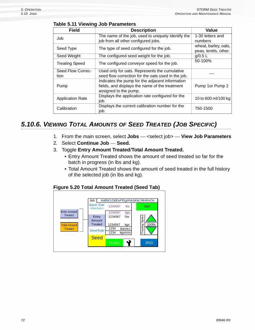
5. OPERATION STORM SEED TREATER
5.10. JOBS OPERATION AND MAINTENANCE MANUAL
5.10.6. VIEWING TOTAL AMOUNTS OF SEED TREATED (JOB SPECIFIC)
1. From the main screen, select Jobs — <select job> — View Job Parameters2. Select Continue Job — Seed.3. Toggle Entry Amount Treated/Total Amount Treated.
• Entry Amount Treated shows the amount of seed treated so far for the batch in progress (in lbs and kg).
• Total Amount Treated shows the amount of seed treated in the full history of the selected job (in lbs and kg).
Figure 5.20 Total Amount Treated (Seed Tab)
Table 5.11 Viewing Job ParametersField Description Value
JobThe name of the job, used to uniquely identify the job from all other configured jobs.
1-30 letters and numbers
Seed Type The type of seed configured for the job.wheat, barley, oats, peas, lentils, other.
Seed Weight The configured seed weight for the job. g/0.5 L
Treating Speed The configured conveyor speed for the job.50-100%
Seed Flow Correc-tion
Used only for oats. Represents the cumulative seed flow correction for the oats used in the job.
---
PumpIndicates the pump for the adjacent information fields, and displays the name of the treatment assigned to the pump.
Pump 1or Pump 2
Application RateDisplays the application rate configured for the job.
10 to 600 ml/100 kg
Calibration Displays the current calibration number for the job.
750-1500
Start
PumpsSeed
END
Entry Amount Treated
Job:
lbs1234567Batch Size<0 for Cont.>
Tre
atin
g S
pee
d
100%
kgs1234567
Seed Rate
1234567 lbs
1234567 kgs
AaBbCcDdEeFfGgHhIiJjKkLlMmNnOo
12341234
lbs/minkgs/min
72 30946 R0
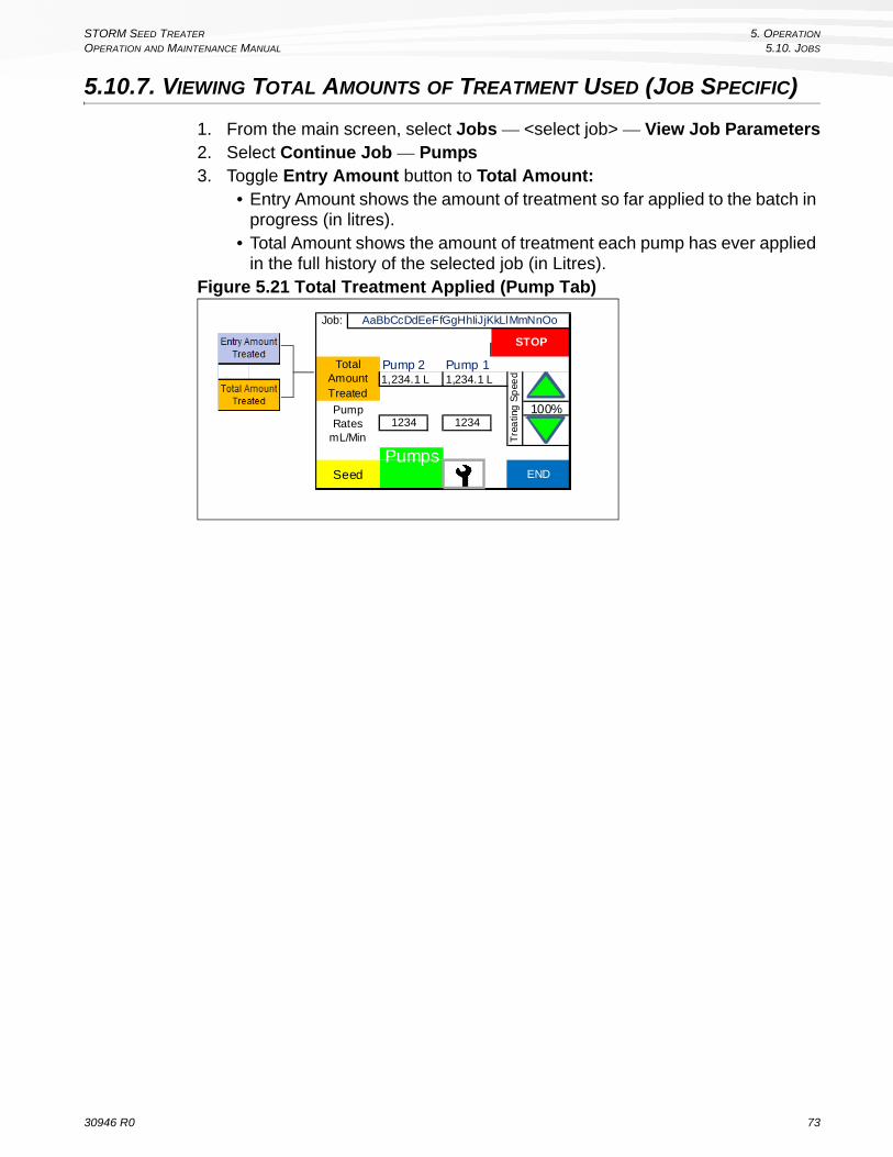
STORM SEED TREATER 5. OPERATION
OPERATION AND MAINTENANCE MANUAL 5.10. JOBS
5.10.7. VIEWING TOTAL AMOUNTS OF TREATMENT USED (JOB SPECIFIC)
1. From the main screen, select Jobs — <select job> — View Job Parameters2. Select Continue Job — Pumps3. Toggle Entry Amount button to Total Amount:
• Entry Amount shows the amount of treatment so far applied to the batch in progress (in litres).
• Total Amount shows the amount of treatment each pump has ever applied in the full history of the selected job (in Litres).
Figure 5.21 Total Treatment Applied (Pump Tab)
Pump 2 Pump 11,234.1 L 1,234.1 L
Seed
STOP
Total Amount Treated
Pump Rates
mL/Min1234 1234
100%
AaBbCcDdEeFfGgHhIiJjKkLlMmNnOo
Tre
atin
g S
pee
d
Job:
PumpsEND
30946 R0 73
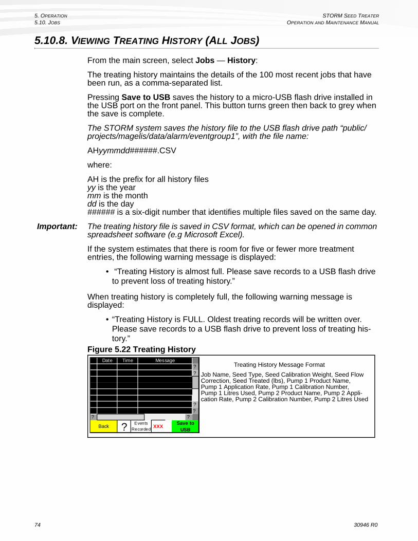
5. OPERATION STORM SEED TREATER
5.10. JOBS OPERATION AND MAINTENANCE MANUAL
5.10.8. VIEWING TREATING HISTORY (ALL JOBS)
From the main screen, select Jobs — History:
The treating history maintains the details of the 100 most recent jobs that have been run, as a comma-separated list.
Pressing Save to USB saves the history to a micro-USB flash drive installed in the USB port on the front panel. This button turns green then back to grey when the save is complete.
The STORM system saves the history file to the USB flash drive path “public/projects/magelis/data/alarm/eventgroup1”, with the file name:
AHyymmdd######.CSV
where:
AH is the prefix for all history files yy is the year mm is the month dd is the day ###### is a six-digit number that identifies multiple files saved on the same day.
Important: The treating history file is saved in CSV format, which can be opened in common spreadsheet software (e.g Microsoft Excel).
If the system estimates that there is room for five or fewer more treatment entries, the following warning message is displayed:
• “Treating History is almost full. Please save records to a USB flash drive to prevent loss of treating history.”
When treating history is completely full, the following warning message is displayed:
• “Treating History is FULL. Oldest treating records will be written over. Please save records to a USB flash drive to prevent loss of treating his-tory.”
Figure 5.22 Treating History
Job Name, Seed Type, Seed Calibration Weight, Seed Flow Correction, Seed Treated (lbs), Pump 1 Product Name, Pump 1 Application Rate, Pump 1 Calibration Number, Pump 1 Litres Used, Pump 2 Product Name, Pump 2 Appli-cation Rate, Pump 2 Calibration Number, Pump 2 Litres Used
Treating History Message Format??
??
? ?
Date Time Message
XXXSave to
USBEvents
Recorded?Back
74 30946 R0
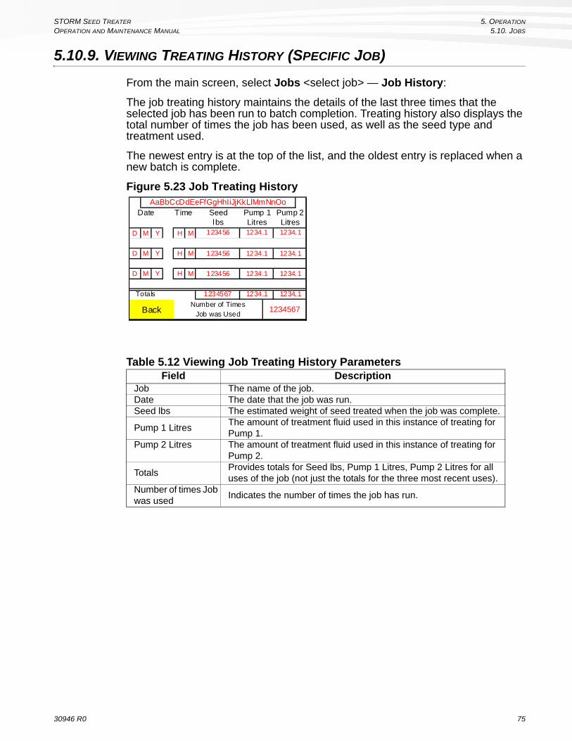
STORM SEED TREATER 5. OPERATION
OPERATION AND MAINTENANCE MANUAL 5.10. JOBS
5.10.9. VIEWING TREATING HISTORY (SPECIFIC JOB)
From the main screen, select Jobs <select job> — Job History:
The job treating history maintains the details of the last three times that the selected job has been run to batch completion. Treating history also displays the total number of times the job has been used, as well as the seed type and treatment used.
The newest entry is at the top of the list, and the oldest entry is replaced when a new batch is complete.
Figure 5.23 Job Treating History
Table 5.12 Viewing Job Treating History ParametersField Description
Job The name of the job.Date The date that the job was run.Seed lbs The estimated weight of seed treated when the job was complete.
Pump 1 LitresThe amount of treatment fluid used in this instance of treating for Pump 1.
Pump 2 Litres The amount of treatment fluid used in this instance of treating for Pump 2.
TotalsProvides totals for Seed lbs, Pump 1 Litres, Pump 2 Litres for all uses of the job (not just the totals for the three most recent uses).
Number of times Job was used
Indicates the number of times the job has run.
D M Y H M
D M Y H M
D M Y H M
1234567Totals
1234.1
1234.1
1234.1
Number of Times Job was Used
1234567
Litres LitresPump 1 Pump 2
AaBbCcDdEeFfGgHhIiJjKkLlMmNnOoSeedlbs
123456
123456
123456
1234.1
1234.1
1234.1
Date Time
1234.1
Back
1234.1
30946 R0 75

5. OPERATION STORM SEED TREATER
5.11. TREATING AND CALIBRATION OPERATION AND MAINTENANCE MANUAL
5.11. TREATING AND CALIBRATION
5.11.1. SEED TREATMENT
Before treating a batch of seed, you must first have on hand the seed treatment intended for use, in sufficient quantity for the amount of seed to be treated.
Any mixing or dilution must be done in advance.
The general sequence for operating the STORM unit to treat seed is as follows:
• “Step 1: Prepare the STORM Pumps for Seed Treating” on page 76• “Step 2: Select a Job to Run” on page 77• “Step 3: Set Batch Parameters and Begin Seed Treatment” on page 79• “Step 4: Monitor Job Until Complete” on page 81• “Cleanup” on page 91
STEP 1: PREPARE THE STORM PUMPS FOR SEED TREATING
The STORM supports various options for
• pump type, • number of ganged pump heads per pump motor, • pump tubing element type per pump head, • nozzle/hose configuration (combined vs. separate flow).
These options generally reflect the operational requirements for specific treatment types.
Before treating:
• Ensure that any required mixing or dilution of treatment has been done, and that the treatment is in a container that is compatible with STORM connectors.
• Ensure that the STORM physical pump and pump tubing element configu-ration is suitable for the job.
• Ensure that the nozzle configuration is set appropriately for the job (com-bined flow or separate flow)
• Review the pump, hose, and tubing element configuration information using the STORM touch-screen, and ensure that it matches the physical pump, hose, and tubing element configuration for the intended job.
76 30946 R0

STORM SEED TREATER 5. OPERATION
OPERATION AND MAINTENANCE MANUAL 5.11. TREATING AND CALIBRATION
STEP 2: SELECT A JOB TO RUN
Note: Instead of running an existing job, the operator can instead either create and immediately run a new job (see “Creating a New Job” on page 64) or copy and immediately run a version of an existing job (“Copy an Existing Job” on page 70).
1. Select the appropriate job from the main Jobs menu (Jobs — select job) or start a new job (see “Creating a New Job” on page 64) and then return to this procedure.
Figure 5.24 Jobs Menu
2. From the Job Options screen for that job, select: • “Start Treating” to run the current job, or • “Copy Parameters to a New Job” to create a new job based on the cur-
rent job (“Copy an Existing Job” on page 70) and return to this procedure.
Figure 5.25 Job Options
3. If the current programmed configuration for either pump is different than those for the selected job (see “View and Configure Pump Setup” on page 61), that pump’s configuration screen is displayed, and the operator is
Jobs 1 - 5
AaBbCcDdEeFfGgHhIiJjKkLlMmNnOoAaBbCcDdEeFfGgHhIiJjKkLlMmNnOo
MoreStart
New JobHistoryBack
StartTreating Delete
JobHistory
Job Name Selected
Back
AaBbCcDdEeFfGgHhIiJjKkLlMmNnOo
Copy Parameters to a New Job
Help
30946 R0 77

5. OPERATION STORM SEED TREATER
5.11. TREATING AND CALIBRATION OPERATION AND MAINTENANCE MANUAL
instructed to ensure that the physical pump and pump tubing element config-uration matches the configuration for the job.
Figure 5.26 Pump Configuration Screens (Pump 1 and Pump 2)
4. Select Continue to proceed and view further job information, or Back to return to the previous screen.
Figure 5.27 Job Parameters 1
Note: Seed Flow Correction is only shown for Oats.
Table 5.13 Pump ConfigurationObjects Description
Pump Head Type Displays the pump type for the position as I/P or L/SMotor Displays #1 or #2, indicating the pump position (pump 1 or pump 2)
Position (label)
Indicates the ganged pump position as 1A, 1B, 1C (for pump 1) or 2A, 2B, 2C (for pump 2). 2A indicates the inner pump head, 2B the middle pump head, and 2C the outer pump head.
Position (block)
The pump tubing element type for each pump position is displayed as one of the following: LS 15, LS 24, LS35, I/P 26, I/P 73, or NONE. Each tubing element type must match the pump it is used on. NONE indicates that the pump head is not used (and may not actually be installed).
Abort Job
Job was created using a dif ferent pump set-up. Configure the pumps to match this diagram. Press
"Continue" when done.
Pump 1
I/P 73 None None
Motor #1
Continue and Update Pump Setup
Position2A
Posit ion2B
P ositi on2C
Positi on2C
Abort Job Continue and Update Pump Setup
Pump 2
Job was created using a dif ferent pump set-up. Configure the pumps to match this diagram. Press
"Continue" when done.
I/P 73 None None
Motor #2
Position2A
Posit ion2B
Job
Seed Type
Continue
Seed Flow Correction 1000
Wheat
Seed Weight 123.1 g/0.5L
AaBbCcDdEeFfGgHhIiJjKkLlMmNnOo
Back
Treating Speed Max
100%Min50%
78 30946 R0

STORM SEED TREATER 5. OPERATION
OPERATION AND MAINTENANCE MANUAL 5.11. TREATING AND CALIBRATION
Figure 5.28 Job Parameters 2
5. On the job parameters screen, make note of the parameters for the job, and ensure that they show the correct treatment. Note the pump usage, and ensure that the STORM pump hoses are set up in the same way, with each pump hose connected to the correct treatment container.
6. From the job parameters screen, perform a calibration check for each pump being used for the selected treatment. See “Select Continue to proceed to save the new job (see “Save Job and Proceed” on page 69 for details on option available when saving a job).” on page 70 for procedures.
Note: Cal check is an optional step that is used to ensure that changing conditions (tubing element wear over time, temperature change, treatment batch differ-ences) do not affect accuracy of treatment application.
7. When the calibration check is complete, ensure that the calibration cylinder is placed back in storage position, and the calibration valves are switched from calibration positions to application positions
8. Select Continue to proceed with the treatment application procedure (see “Step 3: Set Batch Parameters and Begin Seed Treatment” on page 79).
STEP 3: SET BATCH PARAMETERS AND BEGIN SEED TREATMENT
1. From the Job Screen, Select Continue to proceed.2. Read the warning screen that is displayed (see below):
• ensure that the auger is started, the gearbox is in the forward position, and the mixing flight is engaged and turning;
• move calibration valves to treatment setting;• ensure that it is safe to proceed with treating seed.
Figure 5.29 Treatment Warning
Job
Calibration 1234Check Cal
Back
AaBbCcDdEeFfGgHhIiJjKkLlMmNnOo
Application Rate 1234 ml /100kg
Application Rate 1234 ml /100kg Calibration 1234
Check Cal
Continue
AaBbCcDdEeFfGgHhIiJjKkLlMmNn
Pump 2 AaBbCcDdEeFfGgHhIiJjKkLlMmNn
Pump 1
IMPORTANT
1. Ensure that the auger / mixer gearbox lever is in the forward posi tion and that the mixer is turning
2. Move the calibration valves to the treating position3. Make sure it is safe to proceed
Before starting to treat seed:
Continue
30946 R0 79

5. OPERATION STORM SEED TREATER
5.11. TREATING AND CALIBRATION OPERATION AND MAINTENANCE MANUAL
3. From the treatment warning screen, Select Continue to proceed.4. Ensure that the pump hose-end connectors are connected to the treatment
container connector(s).5. Prime the pump(s): Press and hold the Prime button for the selected pump(s)
until treatment fluid begins to exit the application nozzles (this is most accurately indicated by an increase of pressure shown on the gauge for the pump being primed).
Figure 5.30 Prime/Empty Screen
6. Fill the conveyor by holding down Jog Conveyor until one full cleat of seed falls into the treatment application boot.
Important: If the conveyor is not initially filled, metering will be out slightly.
7. Set job parameters for the batch on the Seed Rate tab:• Batch Size: the number of lbs of seed to be treated in this batch
(0-999,999 lbs). • Treating speed: increases or decreases the number of bushels of seed
treated per minute, according to the allowable rates calculated by the sys-tem (50%-100%).
Note: Setting a batch size of “0” will cause the job to run continuously. Batch size can be changed during treatment to reduce the initial batch size before the batch has been completed.
Figure 5.31 Seed Rate Tab Screen
Pump 2 Pump 1Prime Prime
(Push & Hold) (Push & Hold)Empty Empty
Ensure the metering belt is full of seed.Prime pumps before treating.
Seed Meter Jog Conveyor (Push & Hold)
(Push & Hold) (Push & Hold)
Continue
Start
PumpsSeed
END
Entry Amount Treated
Job:
lbs1234567Batch Size<0 for Cont.>
Tre
atin
g S
pee
d
100%
kgs1234567
Seed Rate
1234567 lbs
1234567 kgs
AaBbCcDdEeFfGgHhIiJjKkLlMmNnOo
12341234
lbs/minkgs/min
50% 60% 70% 80% 90% 100%
80 30946 R0

STORM SEED TREATER 5. OPERATION
OPERATION AND MAINTENANCE MANUAL 5.11. TREATING AND CALIBRATION
8. Check the Pumps tab to view pump rates for the job.Figure 5.32 Pumps Tab
9. Ensure that the auger is running, and adjust the auger throttle to between 2/3 and 3/4 of full throttle.
10. Select Start to begin seed treatment by (from either the Seed Rate or Pumps tab). The conveyor will begin to move, and drop seed past the nozzles and into the boot.
11. Slow the auger speed until seed begins to accumulate in the boot. When the seed level in the boot reaches half-full, (roughly half of the boot flight is exposed), and then increase speed until this level is constant.
Important: The boot should be half full when running, with half of the flight exposed to view.
STEP 4: MONITOR JOB UNTIL COMPLETE
During seed treatment, you have the following options:
• Select seed rate or pumps tabs to monitor job progress (Seed or Pumps);• Increase or decrease treating speed;• Start or stop the job in progress (Start or Stop button);• Monitor motor RPM and power supply (see Diagnostics screen).
Important: Increasing or decreasing the treatment rate adjusts the pump rate and conveyor speed.
While the STORM is processing a job, it is important to monitor the following:
• Seed level in Boot: Always ensure that the boot is always half-full (half the boot flight should be exposed above the seed.
• If less than half of the boot flight is visible, increase the speed of the auger.
• If more than half of the boot flight is visible, decrease the speed of the auger.
Pump 2 Pump 11,234.1 L 1,234.1 L
Seed
STOP
Total Amount Treated
Pump Rates
mL/Min1234 1234
100%
AaBbCcDdEeFfGgHhIiJjKkLlMmNnOo
Tre
atin
g S
pee
d
Job:
PumpsEND
WARNING
Failure to regulate auger speed can result in auger plugging, which can cause damage to equipment and endanger personnel.
30946 R0 81

5. OPERATION STORM SEED TREATER
5.11. TREATING AND CALIBRATION OPERATION AND MAINTENANCE MANUAL
• Seed level in hopper: Always ensure that the STORM hopper is fully flooded, and that there is enough seed in the supply to complete the job.
• Treatment fluid level: Always ensure that there is sufficient supply of treat-ment fluid on-hand to complete the job, and do not allow the treatment fluid lines run dry during a job. If a treatment container is close to empty, be pre-pared to pause (Stop) the job and switch to a full container. If a container runs dry during a job: a. stop the job,
b. connect a new treatment container,
c. prime the pump, and
d. resume the job.
When a batch is complete, the conveyor will stop and a “Treating Complete” screen is displayed. For all seed types except oats, a standard screen is always displayed. For oats, a special screen is presented each time that a job is run.
Figure 5.33 Treating Complete
At the standard treatment complete screen, record the displayed treatment infor-mation as needed, and select “Return to Job Options” to return to the main Jobs screen. Either proceed to treat more seed, or clean up the STORM for future use.
Important: OATS: For a job’s first batch complete screen, enter the actual amount of seed treated (as weighed using a calibrated scale). The system calculates a new seed flow correction value to be used in the next batch. Enter “Continue” to proceed to treat the next batch at an optimized treatment coverage. For all batches that follow, the system calculates and provides an estimate for actual seed treated.
STEP 5: COMPLETION
When a job is complete, the operator should use the Flush Out screen functions (Maintenance — Flush Out) to run the pumps backward until the treatment fluid in the lines is returned to the treatment container.
Standard Oats Job: AaBbCcDdEeFfGgHhIiJjKkLlMmNnOo
Seed Treated 1234567890
Treating Complete!
lbs
Treatment UsedPump 1
Treatment Used Pump 2
123456.1 L
123456.1 L
Return to Job Options
Treating Complete!
123,456 lbs
Actual SeedTreated
(from Scale)
0 lbs
Job: AaBbCcDdEeFfGgHhIiJjKkLlMmNnOo
1000
EstimatedSeed Treated
Seed Flow Correction
Return to Job Options
82 30946 R0

STORM SEED TREATER 5. OPERATION
OPERATION AND MAINTENANCE MANUAL 5.11. TREATING AND CALIBRATION
5.11.2. CALIBRATION PROCEDURES
Pump tests are used to calibrate the system to ensure that the amount of treatment being applied to the seed is accurate. There are three stages to calibration, as described below:
• Product flow test• Pump compensation test• Calibration check test
Accurate calibration is determined by measuring the amount of treatment fluid pumped into the calibration cylinder, and then entering the amount pumped into the STORM calibration system.
Important: Before use, the pump tubing element break-in procedure should always be performed once for all new tubing elements (see “Pump Tubing Elements Break-in” on page 50).
PREPARE SYSTEM FOR CALIBRATION
1. Set the calibration valves according to the Calibrate position for the specific pump to be calibrated, as shown on the Operating Procedure decal that is located on the STORM valve assembly (see below).
Figure 5.34 Operating Procedure Decal (Calibration Valve Positions)
Important: If the valves are set incorrectly, damage to equipment may occur when the pump is activated as part of the calibration process.
TO CALIBRATE:
PUMP 2
PUMP 1
2 1
2 1
TO TREAT:TO OPERATE PUMPS 1 & 2:
OPERATING PROCEDURE
Refer to Operator’s Manual for detailedtreating information.
Before operating, check that pump adjustment knob is tightby turning fully clockwise. DO NOT loosen, or metering will not function correctly.
A
ENGAGEDDISENGAGED
A
21905Made in Canada
2 1
3
3 3
30946 R0 83

5. OPERATION STORM SEED TREATER
5.11. TREATING AND CALIBRATION OPERATION AND MAINTENANCE MANUAL
2. Unlatch the calibration cylinder and let it hang freely.Figure 5.35 Unlatching the Calibration Cylinder
STEP 1: PRODUCT FLOW TEST:
1. Ensure that the calibration valves and cylinder are positioned for calibration (see “Prepare System for Calibration” on page 83.)
2. Use the Prime and Empty buttons as required to ensure that the treatment fluid reaches the bottom mark on the cylinder.
3. From the Job screen, select Calibrate or Check Cal for the pump to be calibrated (Pump 1 or Pump 2).
Note: When Check Cal is performed, it uses the calibration number obtained in initial calibration as the starting point for expected results.
Figure 5.36 Select “Calibrate” or “Check Cal”
Min Max
Pump 1 AaBbCcDdEeFfGgHhIiJjKkLlMmNn
Back
Calibrate
Help Continue
AaBbCcDdEeFfGgHhIiJjKkLlMmNn
Treat ing Speed status50% 100%
Application Rate
Application Rate
324 ml/100kg
324 ml/100kgPump 2
Calibration #
Calibrate Calibration #
Job
Back
AaBbCcDdEeFfGgHhIiJjKkLlMmNnOo
Application Rate 324 ml/100kg
Application Rate 324 ml/100kg Calibration # 1000
Check Cal
Continue
AaBbCcDdEeFfGgHhIiJjKkLlMmNn
Pump 2 AaBbCcDdEeFfGgHhIiJjKkLlMmNn
Pump 1
Calibration # 1000Check Cal
84 30946 R0

STORM SEED TREATER 5. OPERATION
OPERATION AND MAINTENANCE MANUAL 5.11. TREATING AND CALIBRATION
4. The system will display the first calibration message screen, warning the operator to set the calibration valves correctly for the pump to be calibrated.
Figure 5.37 Calibration Valves Warning
5. Use the Prime button to fill the calibration cylinder up to roughly 500 ml to ensure that all air bubbles are removed from the line, then press the Empty button to empty the cylinder to the 0 ml mark.
6. Press Start Test to begin the product flow test.Figure 5.38 Product Flow Test (1A)
7. The pump will begin filling the calibration cylinder, and will stop after a set amount of time.
8. Enter the amount that was collected by pressing the touchscreen and then using the touchscreen keypad.
Figure 5.39 Product Flow Test (1B)
Continue
IMPORTANT
1. Confirm connection to the correct pump2. Ensure pump tubing is properly installed3. Make sure liquid system is free of air leaks and flow obstructions4. Set Calibration Valves to the proper positions for the pump being calibrated
Step 1A Product Flow Test
Start Test
Empty(Push & Hold)
Back
Prime
Use the Prime and Empty buttons to set the liquid to
the zero mark on the calibration cylinder.
(Push & Hold)
1234 rpm
Time of Test123.1 Sec
Expected Pump RPM
Step 1B Product Flow Test
Pump RPM1234 rpm
Time of Test123.1 Sec
Enter the Amount
Collected
1234 ml
AbortTest
Continue
30946 R0 85

5. OPERATION STORM SEED TREATER
5.11. TREATING AND CALIBRATION OPERATION AND MAINTENANCE MANUAL
9. Press Continue to proceed. • If the amount collected is less than 800 ml or more than 1200 ml, the system
will declare calibration failure. Empty the calibration cylinder and then press Continue to return to the Job screen.
Figure 5.40 Calibration Failed Message
• If the amount collected is between 980 ml and 1020 ml, the flow test is passed, and no further calibration is required for that pump.
Figure 5.41 Calibration Successful Message
• If the amount collected is between 800 ml and 1200 ml, the system will require the operator to proceed with the next calibration step (pump compen-sation test). Press Continue to Step 2 to proceed with further calibration steps.
Figure 5.42 Product Flow Test Complete (1C)
Calibration Failed.The amount collected in the test is outside of
the expected range. The cause may be equipment or product related. Consult the
Operation Manual or an AGI Service Professional for next steps.
IMPORTANT
Continue
Please empty the calibration cylinder before proceeding.
Empty(Push & Hold)
Congratulations!
CalibrationSuccessful!
IMPORTANT
Please empty the calibration cylinder before proceeding.
EmptyContinue(Push & Hold)
Continueto Step 2
ESC
Step 1C - Product Flow Test for Pump is Complete
86 30946 R0

STORM SEED TREATER 5. OPERATION
OPERATION AND MAINTENANCE MANUAL 5.11. TREATING AND CALIBRATION
STEP 2: PUMP COMPENSATION TEST
During the pump compensation test, the system uses data from the product flow test to compensate for the flow qualities of the treatment product, and adjust pump calibration accordingly.
1. Use the Prime and Empty buttons as required to ensure that the treatment fluid reaches the 0 ml mark on the cylinder.
2. Select Start Test from the Calibration screen.Figure 5.43 Pump Compensation Test (2A)
3. Enter the reading in the field labeled “Enter the Amount Collected”. Figure 5.44 Pump Compensation Test (2B)
4. Press Continue to proceed. • If the amount collected is less than 900 ml or more than 1100 ml, the system
will declare calibration failure. Empty the calibration cylinder and press Con-tinue to return to the Job screen.
Step 2A Pump Compensation Test
Back
Empty 123.1 Sec(Push & Hold)
Use the Prime and Empty buttons to set the liquid to
the zero mark on the calibration cylinder.
Prime(Push & Hold)
Expected Pump RPM
1234 rpm
Time of Test
Start Test
Step 2B Pump Compensation Test
1234 ml
Enter the Amount
Collected
AbortTest
Pump RPM1234 rpm
Time of Test123.1 Sec
Continue
30946 R0 87

5. OPERATION STORM SEED TREATER
5.11. TREATING AND CALIBRATION OPERATION AND MAINTENANCE MANUAL
Figure 5.45 Calibration Failed Message
• If the amount collected is between 980 ml and 1020 ml, the test is passed, and no further calibration is required for that pump.
Figure 5.46 Calibration Successful Message
• If the amount collected is between 900 ml and 1100 ml, the system will require the operator to proceed with the final calibration step (pump calibra-tion check). Press Continue to Step 3 to proceed with further calibration steps.
Figure 5.47 Compensation Test Complete
Calibration Failed.The amount collected in the test is outside of
the expected range. The cause may be equipment or product related. Consult the
Operation Manual or an AGI Service Professional for next steps.
IMPORTANT
Continue
Please empty the calibration cylinder before proceeding.
Empty(Push & Hold)
Congratulations!
CalibrationSuccessful!
IMPORTANT
Please empty the calibration cylinder before proceeding.
EmptyContinue(Push & Hold)
Step 2C - Pump Compensation Test for Pump is Complete
Continueto Step 3
88 30946 R0
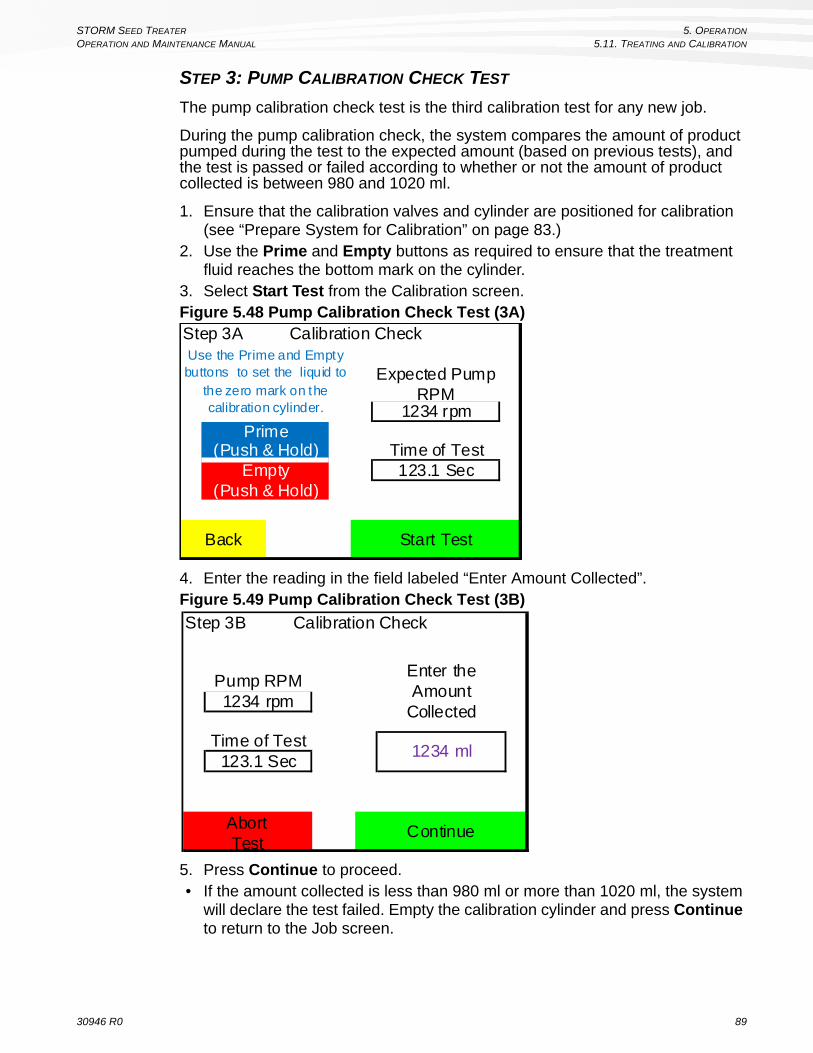
STORM SEED TREATER 5. OPERATION
OPERATION AND MAINTENANCE MANUAL 5.11. TREATING AND CALIBRATION
STEP 3: PUMP CALIBRATION CHECK TEST
The pump calibration check test is the third calibration test for any new job.
During the pump calibration check, the system compares the amount of product pumped during the test to the expected amount (based on previous tests), and the test is passed or failed according to whether or not the amount of product collected is between 980 and 1020 ml.
1. Ensure that the calibration valves and cylinder are positioned for calibration (see “Prepare System for Calibration” on page 83.)
2. Use the Prime and Empty buttons as required to ensure that the treatment fluid reaches the bottom mark on the cylinder.
3. Select Start Test from the Calibration screen.Figure 5.48 Pump Calibration Check Test (3A)
4. Enter the reading in the field labeled “Enter Amount Collected”. Figure 5.49 Pump Calibration Check Test (3B)
5. Press Continue to proceed. • If the amount collected is less than 980 ml or more than 1020 ml, the system
will declare the test failed. Empty the calibration cylinder and press Continue to return to the Job screen.
Step 3A Calibration Check
Start Test
Use the Prime and Empty buttons to set the liquid to
the zero mark on the calibration cylinder.
Expected Pump RPM
1234 rpm
Back
(Push & Hold)Empty
(Push & Hold)
PrimeTime of Test123.1 Sec
Step 3B Calibration Check
Continue
1234 ml
Enter the Amount
Collected
AbortTest
Time of Test123.1 Sec
Pump RPM1234 rpm
30946 R0 89

5. OPERATION STORM SEED TREATER
5.11. TREATING AND CALIBRATION OPERATION AND MAINTENANCE MANUAL
Figure 5.50 Calibration Failed Message
• If the amount collected is between 980 ml and 1020 ml, the test is passed, and no further calibration is required for that pump.
Figure 5.51 Calibration Successful Message
6. Select Continue to return to the Job screen.7. Perform the test for any untested pump if it is to be used for treatment in the
configured job.8. When both pumps have been fully tested, press the Empty button to fully
empty treatment fluid from the lines.9. Confirm that the calibration cylinder is empty, disconnect the cylinder, rinse it
thoroughly, then reconnect it.
Calibration Failed.The amount collected in the test is outside of
the expected range. The cause may be equipment or product related. Consult the
Operation Manual or an AGI Service Professional for next steps.
IMPORTANT
Continue
Please empty the calibration cylinder before proceeding.
Empty(Push & Hold)
ContinueEmpty
(Push & Hold)
Congratulations!
CalibrationSuccessful!
IMPORTANT
Please empty the calibration cylinder before proceeding.
90 30946 R0

STORM SEED TREATER 5. OPERATION
OPERATION AND MAINTENANCE MANUAL 5.11. TREATING AND CALIBRATION
10. Move the cylinder to the storage position.Figure 5.52 Calibration Cylinder, Storage Position
11. Switch the calibration valve from the “Calibrate” position to the “Treating” position.
12. On the Job screen, select Finish.
5.11.3. CLEANUP
The STORM boot and pump tubing should be thoroughly cleaned:
• after general use, • between jobs that use different seeds or treatment fluid
Before cleaning out the boot, pump hoses should be flushed (either with water or with an approved cleaning agent).
DISPOSAL OF RINSE WATER FROM SEED TREATER
• Do not discharge rinse fluid to ground, surface water or septic systems. • Minimize rinse fluid: wash out equipment only when necessary. • Re-use rinse fluid if possible to dilute the next batch of the same or similar for-
mulation (where applicable), but be aware of the potential for cross contami-nation if the next formulation used contains different active ingredients. Factor in the potential for increased concentration of active ingredient, if significant amounts of rinse fluid are used.
Note: Treated seed cleaned out of bottom of auger should not be left on the ground. It must be handled in accordance with the product manufacturer’s recommenda-tions.
TO FLUSH HOSES:
1. Ensure that the intake end of the STORM is raised off the ground with a rinse-fluid catch container under the boot.
2. Open the clean-out hatches on the bottom of the boot fully.
30946 R0 91

5. OPERATION STORM SEED TREATER
5.11. TREATING AND CALIBRATION OPERATION AND MAINTENANCE MANUAL
3. Prepare and place a pail of rinse fluid (water or some other approved cleaning fluid) within reach of the hoses.
4. Disconnect the treatment lines from the treatment containers, and connect a male half adapter to each hose connector.
5. Place the hose ends into a container of rinse fluid.6. Select Maintenance — Flush Out from the main menu to activate the
pumps and flush the lines with rinse fluid. Note: You can either pump the rinse water through in one direction (forward), or
alternate pumping a small volume of water back-and-forth to reduce the amount of rinse water to be disposed.
7. When the lines are determined to be fully flushed, pull the lines out of the pails and position them so that the connectors can drain.
8. Select Maintenance — Flush Out from the main menu to activate the pumps and push air through the line for several minutes to displace any remaining rinse water.
9. Disassemble and clean the treatment filters.10. When the hose connectors are dry, disconnect the female half connectors
and store them for future use.11. Coil the treatment hoses and place the connectors in storage positions.
TO FLUSH OUT THE TREATMENT APPLICATION BOOT
1. Ensure that the intake end of the STORM is raised of the ground with a rinse-water catch container under the boot.
2. Close and secure the clean-out hatch on the bottom of the boot.3. Pour 20 litres of water into the boot through the conveyor top inspection
hatch.4. Run the auger in reverse at idle for 3 to 5 minutes.5. Open the bottom door to release the rinse water into the catch container.6. Use a hose to spray any further residue that may remain in the boot, but
avoid spraying water on the conveyor.
EMPTY UNTREATED SEED FROM THE CONVEYOR AND HOPPER
Untreated seed that remains in the intake hopper and conveyor can be dumped through the conveyor’s bottom clean-out hatch into a clean catch container.
1. Ensure that the intake end of the STORM is raised of the ground with a clean catch container positioned under the conveyor bottom clean-out hatch.
2. Open the conveyor clean-out hatch.3. Select Maintenance — Flush Out from the main menu, and ensure that both
pumps are set to OFF and the conveyor is set to ON.4. Set the conveyor direction to Reverse.5. Select Start to engage the conveyor and begin emptying the intake hopper
and conveyor contents into the catch container. 6. Select Stop to stop the conveyor.7. Remove the catch container of untreated seed, and close and secure the
clean-out hatch.
92 30946 R0

STORM SEED TREATER 5. OPERATION
OPERATION AND MAINTENANCE MANUAL 5.12. PUMP AND CONVEYOR CONTROLS
5.12. PUMP AND CONVEYOR CONTROLS
5.12.1. FLUSH OUT
The Flush Out function allows the operator to set pump and the conveyor direction (forward or reverse), and specify the state (on or off) for each when START is pressed.
From the main menu, select:
Maintenance — Flush Out
Set the conveyor direction (forward or reverse) and state (on or off) to reflect the conveyor action when START is selected.
Set the pumps direction (Forward or Reverse, to apply to both pumps) and state (on or off for each pump) to reflect the pump action when START is selected.
• Select START to engage the setting.• Select STOP to disengage the settings.
Figure 5.53 Flush Out Menu
5.12.2. TRANSFER AND MIX
See the documentation included with the Transfer and Mix kit for further infor-mation.
START
Back
On
Off
On
Conveyor
Pump 1
Pump 2Forward
Reverse
Use for flushing system with water or cleaning agent and for clearing the conveyor of seed
30946 R0 93

5. OPERATION STORM SEED TREATER
5.13. DIAGNOSTIC INFORMATION OPERATION AND MAINTENANCE MANUAL
5.13. DIAGNOSTIC INFORMATION
5.13.1. VIEW LIFETIME TOTAL USE
Lifetime total use is the amount of time that the STORM has spent actively treating seed, and does not include the amount of time spend powered up but not treating seed.
From the main menu, select Maintenance:
Figure 5.54 Maintenance Menu
Table 5.14 Maintenance Menu InformationItem Description
Lifetime Total UseShows the total number of hours the unit has actively treated seeds (0-999999 h).
Lifetime Total Use
Back
123456 Hrs
Flush Out
94 30946 R0

STORM SEED TREATER 5. OPERATION
OPERATION AND MAINTENANCE MANUAL 5.13. DIAGNOSTIC INFORMATION
5.13.2. VIEW DIAGNOSTICS
• Pre-operational diagnostics can be viewed before running a job, and are used to verify that the conveyor and pumps are reporting adequate supply voltages before a job is running.
• Operational diagnostics are viewed while a job is running, and can be used to determine in the overall system performance is adequate by providing access information related to system performance under operational load.
To view pre-operational diagnostics, from the main menu select:
To view operational diagnostics, select the wrench symbol on any the Seed or Pumps screen of a running job.
Figure 5.55 Diagnostics Screens
Table 5.15 Pre-operational Diagnostic Information
Table 5.16 Operational Diagnostic Information
Items Description
Mains voltage conveyorThe voltage supply measured at the conveyor. Should be between 115 and 130 VAC.
Mains voltage Pump 1The voltage supply measured at the Pump 1 motor. Should be between 115 and 130 VAC.
Mains voltage Pump 2The voltage supply measured at the Pump 2 motor.Should be between 115 and 130 VAC.
Conveyor status Conveyor motor status.Pump 1 status Pump 1 motor status.Pump 2 status Pump 2 motor status.
Items DescriptionConveyor Conveyor speed (belt RPM).Conveyor Motor Conveyor motor speed (RPM).Pump 1 Pump 1 motor speed (RPM).Pump 2 Pump 2 motor speed (RPM).
Mains VoltageSupply voltage, as detected by the control box. Should be between 115 and 130 VAC.
Total Amps Total system power draw, as measured by the control box (Amps).
Maintenance —
Pre-operational Diagnostics Operational Diagnostics
Mains Voltage Conveyor 123.1 VoltsMains Voltage Pump 1 123.1 VoltsMains Voltage Pump 2 123.1 Volts
Conveyor Status AaBbCcDdPump 1 Status AaBbCcDdPump 2 Status AaBbCcDd
NOTE: Voltages should be between 115 and 130 Volts
Back
ConveyorConveyor MotorPump 1Pump 2Mains VoltageTotal Amps
12.1123412341234123.112.1
RPMRPMRPMRPM
Job:
Tre
atin
g S
pee
d
100%
AaBbCcDdEeFfGgHhIiJjKkLlMmNnOo
VoltsAmps
STOP
Seed Pumps END
30946 R0 95
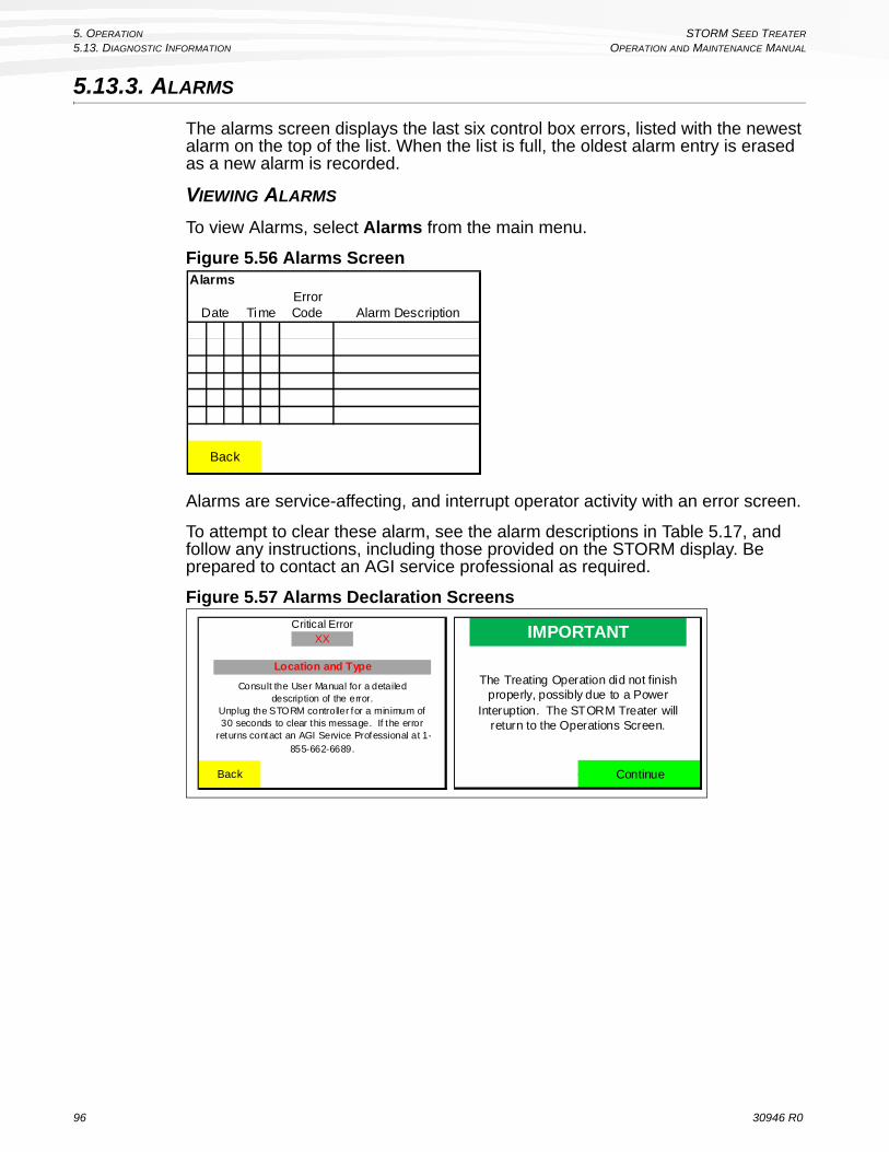
5. OPERATION STORM SEED TREATER
5.13. DIAGNOSTIC INFORMATION OPERATION AND MAINTENANCE MANUAL
5.13.3. ALARMS
The alarms screen displays the last six control box errors, listed with the newest alarm on the top of the list. When the list is full, the oldest alarm entry is erased as a new alarm is recorded.
VIEWING ALARMS
To view Alarms, select Alarms from the main menu.
Figure 5.56 Alarms Screen
Alarms are service-affecting, and interrupt operator activity with an error screen.
To attempt to clear these alarm, see the alarm descriptions in Table 5.17, and follow any instructions, including those provided on the STORM display. Be prepared to contact an AGI service professional as required.
Figure 5.57 Alarms Declaration Screens
Alarms
Alarm DescriptionDate TimeErrorCode
Back
Back
Consult the User Manual for a detailed description of the error.
Unplug the STORM controller for a minimum of 30 seconds to clear this message. If the error
returns contact an AGI Service Professional at 1-855-662-6689.
Critical ErrorXX
Location and Type
IMPORTANT
The Treating Operation did not finish properly, possibly due to a Power
Interuption. The STORM Treater will return to the Operations Screen.
Continue
96 30946 R0
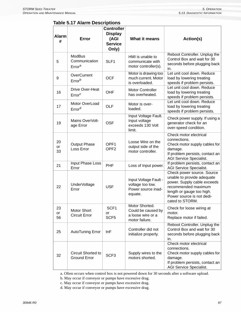
STORM SEED TREATER 5. OPERATION
OPERATION AND MAINTENANCE MANUAL 5.13. DIAGNOSTIC INFORMATION
Table 5.17 Alarm Descriptions
Alarm#
Error
Controller Display
(AGI Service Only)
What it means Action(s)
5ModBus Communication Errora
SLF1HMI is unable to communicate with motor controller(s).
Reboot Controller. Unplug the Control Box and wait for 30 seconds before plugging back in.
9OverCurrent
ErrorbOCF
Motor is drawing too much current. Motor is overloaded.
Let unit cool down. Reduce load by lowering treating speeds if problem persists.
16Drive Over-Heat
ErrorcOHF
Motor Controller has overheated.
Let unit cool down. Reduce load by lowering treating speeds if problem persists.
17Motor OverLoad
ErrordOLF
Motor is over-loaded.
Let unit cool down. Reduce load by lowering treating speeds if problem persists.
19Mains OverVolt-age Error
OSF
Input Voltage Fault. Input voltage exceeds 130 Volt limit.
Check power supply. If using a generator check for an over-speed condition.
20or33
Output Phase Loss Error
OPF1OPF2
Loose Wire on the output side of the motor controller.
Check motor electrical connections.Check motor supply cables for damage.If problem persists, contact an AGI Service Specialist.
21Input Phase Loss Error
PHF Loss of Input power.If problem persists, contact an AGI Service Specialist.
22UnderVoltage Error
USF
Input Voltage Fault - voltage too low. Power source inad-equate.
Check power source. Source unable to provide adequate power. Supply cable exceeds recommended maximum length or gauge too high. Power source is not dedi-cated to STORM.
23or56
Motor Short Circuit Error
SCF1orSCF5
Motor Shorted. Could be caused by a loose wire or a motor failure.
Check for loose wiring at motor.Replace motor if failed.
25 AutoTuning Error tnFController did not initialize properly.
Reboot Controller. Unplug the Control Box and wait for 30 seconds before plugging back in.
32Circuit Shorted to Ground Error
SCF3Supply wires to the motors shorted.
Check motor electrical connections.Check motor supply cables for damage.If problem persists, contact an AGI Service Specialist.
a. Often occurs when control box is not powered down for 30 seconds after a software upload.b. May occur if conveyor or pumps have excessive drag.c. May occur if conveyor or pumps have excessive drag.d. May occur if conveyor or pumps have excessive drag.
30946 R0 97

5. OPERATION STORM SEED TREATER
5.13. DIAGNOSTIC INFORMATION OPERATION AND MAINTENANCE MANUAL
98 30946 R0
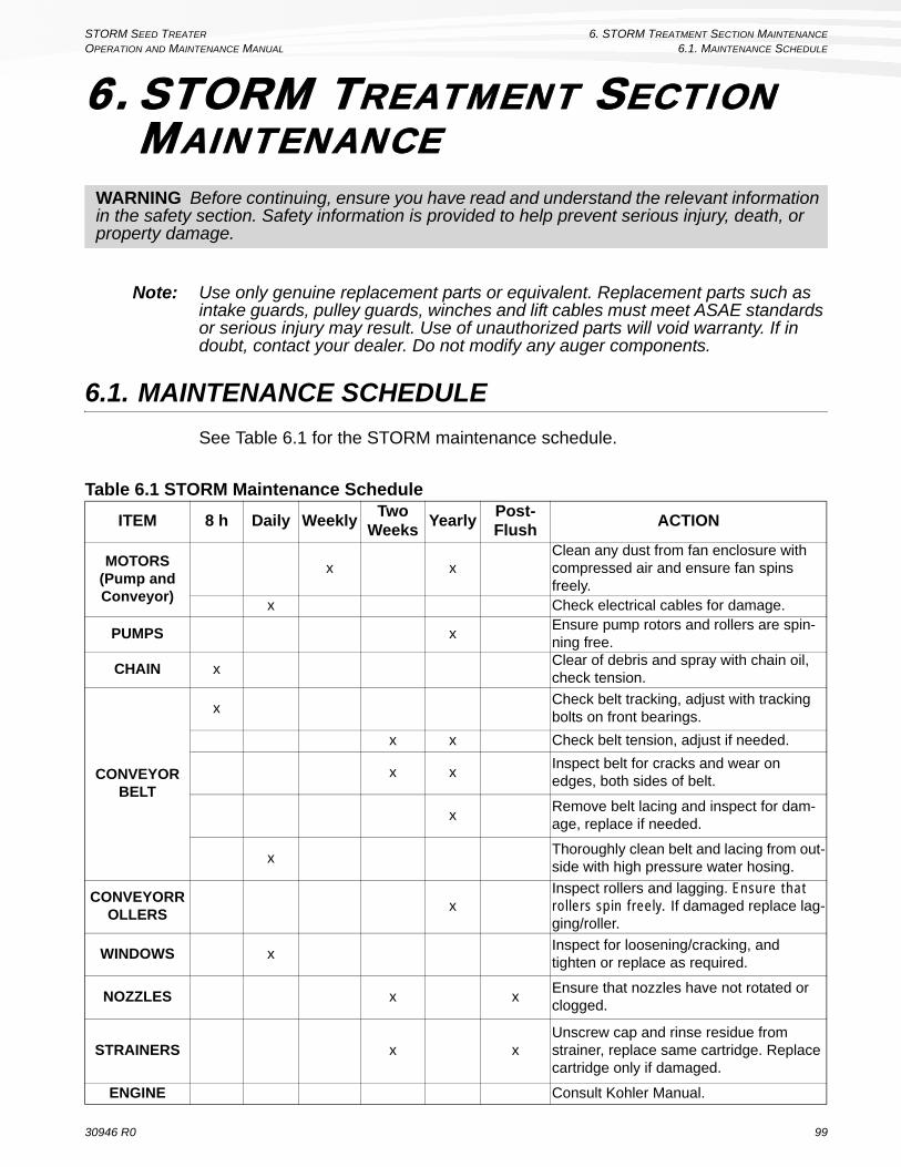
STORM SEED TREATER 6. STORM TREATMENT SECTION MAINTENANCE
OPERATION AND MAINTENANCE MANUAL 6.1. MAINTENANCE SCHEDULE
6. STORM TREATMENT SECTION MAINTENANCE
Note: Use only genuine replacement parts or equivalent. Replacement parts such as intake guards, pulley guards, winches and lift cables must meet ASAE standards or serious injury may result. Use of unauthorized parts will void warranty. If in doubt, contact your dealer. Do not modify any auger components.
6.1. MAINTENANCE SCHEDULE
See Table 6.1 for the STORM maintenance schedule.
WARNING Before continuing, ensure you have read and understand the relevant information in the safety section. Safety information is provided to help prevent serious injury, death, or property damage.
Table 6.1 STORM Maintenance Schedule
ITEM 8 h Daily WeeklyTwo
WeeksYearly
Post-Flush
ACTION
MOTORS(Pump and Conveyor)
x xClean any dust from fan enclosure with compressed air and ensure fan spins freely.
x Check electrical cables for damage.
PUMPS xEnsure pump rotors and rollers are spin-ning free.
CHAIN xClear of debris and spray with chain oil, check tension.
CONVEYORBELT
xCheck belt tracking, adjust with tracking bolts on front bearings.
x x Check belt tension, adjust if needed.
x xInspect belt for cracks and wear on edges, both sides of belt.
xRemove belt lacing and inspect for dam-age, replace if needed.
xThoroughly clean belt and lacing from out-side with high pressure water hosing.
CONVEYORROLLERS
xInspect rollers and lagging. Ensure that rollers spin freely. If damaged replace lag-ging/roller.
WINDOWS xInspect for loosening/cracking, and tighten or replace as required.
NOZZLES x xEnsure that nozzles have not rotated or clogged.
STRAINERS x xUnscrew cap and rinse residue from strainer, replace same cartridge. Replace cartridge only if damaged.
ENGINE Consult Kohler Manual.
30946 R0 99

6. STORM TREATMENT SECTION MAINTENANCE STORM SEED TREATER
6.2. PREPARING FOR STORAGE OPERATION AND MAINTENANCE MANUAL
6.2. PREPARING FOR STORAGE
See Table 6.3 for a list of activities required to prepare the STORM assembly for seasonal storage. See the operation manual for the equipped auger for auger-specific information.
Table 6.2 Seasonal Storage Activities and MaintenanceITEM Activity/Maintenance
Grease pointsCheck all grease points (bearings, zerks, chains), and ensure that they are sufficiently well greased.
Bolts and rivetsInspect all bolts and rivets. Tighten loose bolts and replace any rivets that are loose or missing.
Control Box Depress emergency stop button.
Conveyor, belt, and rollers
Check chain for grease condition.Ensure the belt is thoroughly clean.Run conveyor forward and backward: check for tracking prob-lems, unusual noise, and stiff rollers.Inspect edge of lacing with contact cement or cyanoacrylate based adhesivePlace into transport position and lock in place.
Pumps and hoses
Flush all lines, blow out with compressed air.Disassemble and clean treatment filters.Fill lines with antifreeze.Ensure pump shoe are open to remove pressure on pump tubing elements.
Storm Components
Cover unit using supplied covers.
100 30946 R0

STORM SEED TREATER 6. STORM TREATMENT SECTION MAINTENANCE
OPERATION AND MAINTENANCE MANUAL 6.3. PRE-SEASON MAINTENANCE
6.3. PRE-SEASON MAINTENANCE
See Table 6.2 for a list of activities recommended to prepare the STORM assembly for use after seasonal storage. See the operation manual for the equipped auger for auger-specific information.
Before proceeding to treat seed, it is recommended that the operator also follow the pre-operational checks in “Pre-operational checks (first 1000 bu)” on page 51.
Table 6.3 Preseason MaintenanceITEM Activity/Maintenance
Grease pointsCheck all grease points (bearings, zerks, chains), and ensure that they are sufficiently well greased.
Bolts and rivetsInspect all bolts and rivets. Tighten loose bolts and replace any rivets that are loose or missing.
Control BoxRelease emergency stop button.Check for software updates and upgrade system software if available.
Conveyor, belt, and rollers
Check chain for grease condition.Ensure the belt is thoroughly clean.Run conveyor forward and backward: check for tracking prob-lems, unusual noise, and stiff rollers.Inspect edge of lacing with contact cement or cyanoacrylate based adhesive
Pumps and hoses
Drain and collect antifreeze from treatment lines. Store the antifreeze for further use or dispose of safely.Flush all hoses and lines with water, and dispose of rise-water safely (it will contain anti-freeze if proper storage precautions were taken).Check all connectors and hoses for kinks, leaks, or wear.Ensure pump shoes are closed.Run pumps forward and backward, and check for any unusual noise or actions.
30946 R0 101

6. STORM TREATMENT SECTION MAINTENANCE STORM SEED TREATER
6.3. PRE-SEASON MAINTENANCE OPERATION AND MAINTENANCE MANUAL
102 30946 R0
STORM SEED TREATER 7. STORM AUGER SECTION MAINTENANCE
OPERATION AND MAINTENANCE MANUAL 7.1. FLUIDS & LUBRICANTS
7. STORM AUGER SECTION MAINTENANCE
The STORM has been designed and manufactured to meet the highest standards, while requiring minimal maintenance. Following a careful service and maintenance program will provide many years of trouble-free service.
When performing adjustments, service, or repairs:
• Always take safety into consideration and note “Maintenance Safety” on page 9.
• Use extra caution when cleaning and servicing augers because flighting edges can become sharp.
• Follow proper procedures when mounting a tire on a rim. If in doubt, have a qualified tire repair service perform the required maintenance.
7.1. FLUIDS & LUBRICANTS
ENGINE OIL
Refer to engine operation manual for recommended oil usage.
GEAR OIL
Use SAE approved 90W or equivalent gear oil.
HYDRAULIC OIL
An ISO viscosity 32 heavy duty industrial hydraulic mineral oil is recommended.
GREASE
Use SAE multi-purpose high-temperature grease with extreme pressure (EP) performance or SAE multi-purpose lithium based grease.
WARNING Before continuing, ensure you have read and understand the relevant information in the safety section. Safety information is provided to help prevent serious injury, death, or property damage.
NOTICE
Do not modify the equipment.
Unauthorized modification may impair the function or safety of the equipment, could affect the life of the equipment, and will void your warranty.
30946 R0 103

7. STORM AUGER SECTION MAINTENANCE STORM SEED TREATER
7.2. MAINTENANCE INTERVALS OPERATION AND MAINTENANCE MANUAL
7.1.1. STORAGE & HANDLING
Always follow manufacturer’s guidelines for the safe and effective storage and handling of lubricants.
Your machine can operate at top efficiency only if clean lubricants are used. Use clean containers to handle all lubricants. Store them in an area protected from dust, moisture, and other contaminants.
7.2. MAINTENANCE INTERVALS
Refer to Section 7.3. for details of service.
Table 7.1 Maintenance IntervalsTime Period
Mai
nte
nan
ce P
roce
du
re
Dai
ly (
8000
)BU
Per
iod
ical
ly (
40,0
00)B
U
An
nu
ally
(B
efo
re S
tora
ge)
An
nu
ally
(A
fter
Sto
rag
e)
Visually Inspect the Unit 7.3.1. XCheck engine oil level 7.3.7. XCheck Air Filter 7.3.7. XService Upper Chain Drive 7.3.2. XService Belts 7.3.12. XGrease Machine 7.3.3. XCheck Gear Box Oil Level 7.3.8. XClean Machine 7.3.4. XService Engine 7.3.7. XRepack Wheel Bearings 7.3.5. XTighten Wheel Bolts 7.3.6. XChange Gear Box Oil 7.3.9. XChange Hydraulic Oil Filter 7.3.10. XAdd or Replace Hydraulic Oil 7.3.11. X
104 30946 R0
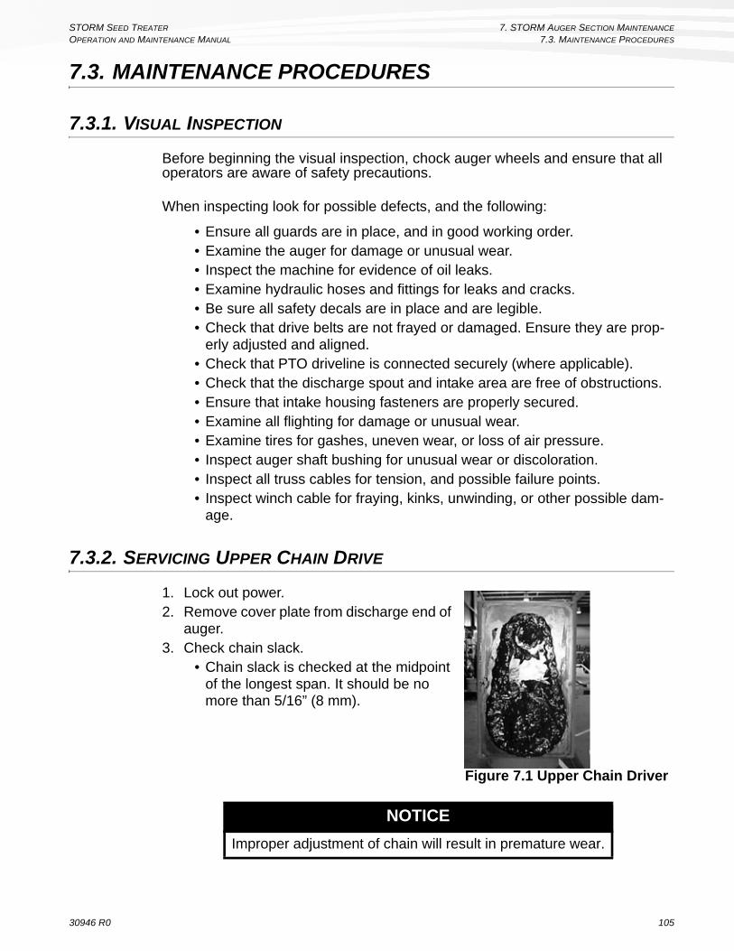
STORM SEED TREATER 7. STORM AUGER SECTION MAINTENANCE
OPERATION AND MAINTENANCE MANUAL 7.3. MAINTENANCE PROCEDURES
7.3. MAINTENANCE PROCEDURES
7.3.1. VISUAL INSPECTION
Before beginning the visual inspection, chock auger wheels and ensure that all operators are aware of safety precautions.
When inspecting look for possible defects, and the following:
• Ensure all guards are in place, and in good working order.• Examine the auger for damage or unusual wear.• Inspect the machine for evidence of oil leaks.• Examine hydraulic hoses and fittings for leaks and cracks.• Be sure all safety decals are in place and are legible. • Check that drive belts are not frayed or damaged. Ensure they are prop-
erly adjusted and aligned.• Check that PTO driveline is connected securely (where applicable).• Check that the discharge spout and intake area are free of obstructions.• Ensure that intake housing fasteners are properly secured.• Examine all flighting for damage or unusual wear.• Examine tires for gashes, uneven wear, or loss of air pressure. • Inspect auger shaft bushing for unusual wear or discoloration. • Inspect all truss cables for tension, and possible failure points.• Inspect winch cable for fraying, kinks, unwinding, or other possible dam-
age.
7.3.2. SERVICING UPPER CHAIN DRIVE
1. Lock out power.2. Remove cover plate from discharge end of
auger.3. Check chain slack.
• Chain slack is checked at the midpoint of the longest span. It should be no more than 5/16” (8 mm).
NOTICE
Improper adjustment of chain will result in premature wear.
Figure 7.1 Upper Chain Driver
30946 R0 105

7. STORM AUGER SECTION MAINTENANCE STORM SEED TREATER
7.3. MAINTENANCE PROCEDURES OPERATION AND MAINTENANCE MANUAL
4. Adjust the chain slack.• Remove the connecting link from the chain.• Remove a link from the chain; if the chain will not fit with one link removed,
add a half link to the chain and replace.5. Grease the chain with appropriate lubricant (Section 7.1.)6. Reattach cover plate.
7.3.3. GREASING MACHINE
Important: Original equipment bearings used by Wheatheart are sealed units and will not accept grease.
1. Lockout all power.2. Use grease recommended in Section 7.1. to grease the upper chain drive
grease zerk and the boot auger flight bushing (located under the hitch on the boot).
3. Use only a hand-held grease gun.4. Wipe grease fitting with a clean cloth before greasing to avoid injecting dirt
and grit.5. If a fitting will not take grease, remove and clean thoroughly. Also clean
lubricant passageway. Replace fitting if necessary.6. Replace and repair broken fittings immediately.
7.3.4. CLEANING MACHINE
1. Lockout all power.2. Clean out excess seed from auger tube and intake.3. Make sure nothing is obstructing the auger intake so water can run out.4. Wash the tube with a water hose or pressure washer until all dirt, mud, debris,
or residue is washed from the auger.5. Provide sufficient time for the water to drain from the auger.
7.3.5. REPACKING WHEEL BEARINGS
1. Block wheels and ensure unit is stable.2. Remove the wheel bolts and the wheels.3. Remove the wheel bearing and pack with grease. Refer to Section 7.1. for
recommended grease.
106 30946 R0

STORM SEED TREATER 7. STORM AUGER SECTION MAINTENANCE
OPERATION AND MAINTENANCE MANUAL 7.3. MAINTENANCE PROCEDURES
7.3.6. TIGHTENING WHEEL BOLTS
1. Clean wheel and hub mounting surfaces to ensure there is no rust or debris.2. Install the wheel and “finger tighten” the wheel bolts. Inspect to make sure the
wheel is sitting flush with the hub.3. Tighten the wheel bolts with a torque wrench to 80 ft-lb (±10 ft-lb) of torque.
Note: Tighten the wheel bolts in a diagonal pattern as in Figure 7.2.
Figure 7.2 Diagonal Pattern
7.3.7. SERVICE ENGINE
1. See engine operation manual for service requirements.
7.3.8. CHECKING GEAR BOX OIL LEVELS
1. Lock out all power.2. Remove oil filler plug.3. Make sure the gearbox is half full (center of cross shaft) and free of foreign
objects. Gearbox should be level when checking gears.
7.3.9. CHANGING GEARBOX OIL
1. Remove guards and gearbox from auger.2. Place a pan under the drain plug.3. Use a wrench and remove the drain plug.4. Loosen the filler plug so air can enter the gearbox and the oil will drain freely.5. Allow the oil to drain completely.6. Replace the drain plug.7. Add oil until the gearbox is half full (center of cross shaft) and replace filler
plug. Gearbox should be level when checking or refilling. Do not overfill.8. Reinstall gearbox and guards.
30946 R0 107

7. STORM AUGER SECTION MAINTENANCE STORM SEED TREATER
7.3. MAINTENANCE PROCEDURES OPERATION AND MAINTENANCE MANUAL
Figure 7.3 Gearbox
7.3.10. CHANGING THE HYDRAULIC OIL FILTER
Change the hydraulic oil filter once a year (minimum), and more often according to the number of hours of use specified by the oil filter manufacturer.
7.3.11. ADDING OR REPLACING HYDRAULIC FLUID
You will be required to top up the hydraulic tank occasionally to make up for fluid losses that may occur (e.g. changing the oil filter or other hydraulic components). When adding hydraulic oil to the hydraulic tank, make sure that the oil you are adding is compatible with the oil already in the tank.
After all PTO kit components have been installed correctly, fill the hydraulic tank with hydraulic oil as follows:
1. Remove the hydraulic tank cap.2. Add hydraulic oil to the hydraulic tank, but do not overfill (leave space at the
top of the tank).3. Slowly extend and retract all hydraulic cylinders until air is displaced from the
hydraulic system.4. Add additional fluid to make up for air displaced from hoses, but do not
overfill the tank.5. Replace and tighten the tank cap.
NOTICE
Failure to replace the oil filter regularly will contribute to wear of hydraulic components, and may decrease the effective life span of the hydraulic fluid.
NOTICE
Topping up the hydraulic tank with an incompatible oil may decrease the post pounder’s performance, and may damage hydraulic components.
108 30946 R0

STORM SEED TREATER 7. STORM AUGER SECTION MAINTENANCE
OPERATION AND MAINTENANCE MANUAL 7.3. MAINTENANCE PROCEDURES
Drain and replace the hydraulic fluid when it has exceeded its recommended number of hours of usage. The effective lifespan of a hydraulic oil depends on the way the post pounder has been maintained and operated, as well as the specifications of the oil used. Refer to the hydraulic oil manufacturer’s specifica-tions for information about effective oil lifespan.
7.3.12. REPLACING BELTS
1. Lock out all power.2. Make sure that the belt engaging lever is disengaged.
3. On motor drive: Remove pulley shield at motor if necessary (belts may slip past pulley without removing shield). If belts do not come off easily, the engine mounting bolts will have to be loosened and the engine pushed toward the intake end of the auger.
4. The new auger belts can now be put in place. Make sure to route the belt over the idler pulley.
5. Follow the procedure in Section 7.3.13. for the proper belt tension.6. Re-attach shield.
7.3.13. TIGHTENING BELTS
1. Lock out all power.2. Engage the belt engaging lever. 3. Loosen the bolts on the engine mount shown in Figure 7.4.
Figure 7.4 Engine Mount Bolts
7. Slide the engine back (towards the spout) until there is adequate tension on the belt. If the alignment of the pulleys needs adjustment, slide the engine left or right until the pulleys line up.
NOTICE
Failure to change the hydraulic fluid after it has exceeded its recommended life span will lead to increased wear and damage of hydraulic components.
30946 R0 109

7. STORM AUGER SECTION MAINTENANCE STORM SEED TREATER
7.3. MAINTENANCE PROCEDURES OPERATION AND MAINTENANCE MANUAL
8. Re-tighten the engine mount bolts and torque as shown in the tables in Section 9.
9. Minor tension adjustments can be made by sliding the idler up or down. Idler shown in Figure 7.5.
Figure 7.5 Belt Idler
110 30946 R0

STORM SEED TREATER 8. TROUBLESHOOTING
OPERATION AND MAINTENANCE MANUAL
8. TROUBLESHOOTINGSee Table 8.1 for troubleshooting information for problems that relate to the STORM auger section.
For problems related directly to the STORM seed treatment section, see “Seed Treating Section Troubleshooting” on page 114.
Table 8.1 STORM Auger Section Troubleshooting
Problem Possible Cause Remedy
Excessive noise or vibra-tion.
*Remember to follow proper break-in proce-dures—auger may run rough until tube is pol-ished. If noise is extreme from outset or con-tinuous after several loads of seed are fed, continue with troubleshoot-ing below
Chatter from wooden bearings.
Spray penetrating lubricant between shaft and bearing surface. Bearings will break in over time.*If replacement of a bearing becomes neces-sary, split bearings are available to avoid having to slide all bearings off drive-shaft.
Truss cables incorrectly adjusted.
Support end of auger and adjust cables so auger is flat or curves slightly upwards.Check the side to side alignment of the truss cables and adjust as necessary.
Flighting peeled back due to plugging.
Inspect spout end of auger for flight condition. Remove and replace flight sections as neces-sary.
Top drive inadequately lubri-cated.
Fill to appropriate level with grease.Top drive is not designed to be filled with oil.
Bent flighting sections.
Support auger and remove all flight sections. Check for straightness of flight stubs by rolling across flat concrete section. Straighten stub or replace as necessary. Take care not to bend flighting when reinstalling.
Obstruction in tube.Visually inspect for cloth or trash wrapped around flighting, or build-up of gum from oily crops such as flax or canola.
Drive belts jumping off pul-leys.
Motor misaligned.Ensure drive and driven pulleys are correctly aligned.
Belts mismatched.Check manual for correct belt sizes and only replace in pairs.
Belt tension inadequate.Maintain correct tension as per Assembly sec-tion.
30946 R0 111

8. TROUBLESHOOTING STORM SEED TREATER
OPERATION AND MAINTENANCE MANUAL
Shear bolts fail repeatedly.
Incorrect shear bolt type.Replace with correct part number. Westfield shear bolts are specifically designed to provide correct driveline protection.
Shear bolt hole worn out-of-round.
Frequent use of the incorrect shear bolt size can wear the mounting hole creating a “scissor effect,” which will require replacement of the affected parts.
Corn spreaders in bin unable to keep up with auger output.
Slow down auger or remove corn spreaders.
Flighting peeled back as a result of plugging.
Occurs when bin has overfilled, or corn spread-ers restrict end of discharge. Inspect flighting at discharge end of auger. If necessary, replace flighting.
Driveline failure (bearing, gear-box, etc.).
See Maintenance section.
Premature wear on auger tubes.
Auger being run at low capacity or empty for extended period of time.
Frequently occurs on farms using grain wagons. Auger should not be left unattended when filling bins. Depending on application, a belt conveyor may be more appropriate.Bent flighting.
Flighting allowed to wear beyond normal point of replace-ment.
When flighting becomes razor-thin at intake, replacement is critical. Since flight material is double thickness at welded lap joints, high spots on flight occur and can accelerate spot tube wear.
The auger does not turn.
auger is plugged or obstructed
identify and remove obstruction
drive belt is slippingadjust the tension of the belt
fully engage the belt release
a bearing is seized identify the bearing and replace
a chain is broken identify the chain and repair or replace
gearbox is seized fix or replace the gearbox
gearbox coupler bolt is bro-ken or missing
replace the bolt
The bottom auger will not turn.
center coupler bolt is broken or missing
replace the bolt
Auger is noisy.
obstruction in the auger identify and remove obstruction
auger shaft bolts are loose or damaged
tighten or replace bolts
auger shaft is bent repair or replace auger
flighting is damaged repair or replace auger
worn bearing repair or replace bearing
low gear oil levelinspect the gearbox, replace if damaged or add oil if not damaged
upper chain drive loose tighten the chain as required
Table 8.1 STORM Auger Section Troubleshooting
Problem Possible Cause Remedy
112 30946 R0
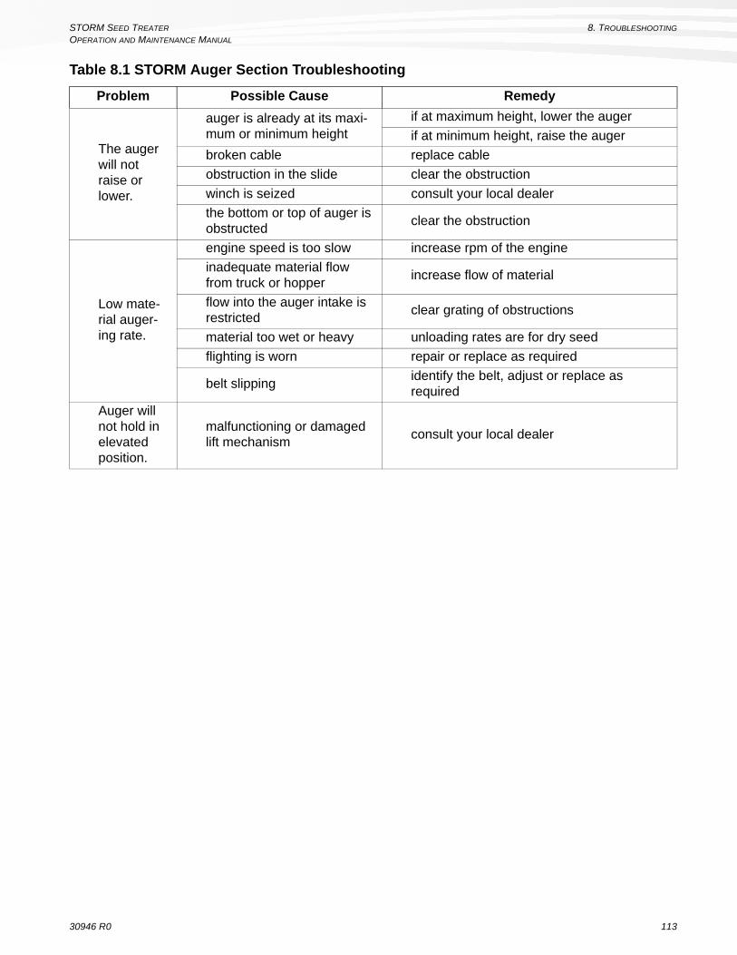
STORM SEED TREATER 8. TROUBLESHOOTING
OPERATION AND MAINTENANCE MANUAL
The auger will not raise or lower.
auger is already at its maxi-mum or minimum height
if at maximum height, lower the auger
if at minimum height, raise the auger
broken cable replace cable
obstruction in the slide clear the obstruction
winch is seized consult your local dealer
the bottom or top of auger is obstructed
clear the obstruction
Low mate-rial auger-ing rate.
engine speed is too slow increase rpm of the engine
inadequate material flow from truck or hopper
increase flow of material
flow into the auger intake is restricted
clear grating of obstructions
material too wet or heavy unloading rates are for dry seed
flighting is worn repair or replace as required
belt slippingidentify the belt, adjust or replace as required
Auger will not hold in elevated position.
malfunctioning or damaged lift mechanism
consult your local dealer
Table 8.1 STORM Auger Section Troubleshooting
Problem Possible Cause Remedy
30946 R0 113

8. TROUBLESHOOTING STORM SEED TREATER
8.1. SEED TREATING SECTION TROUBLESHOOTING OPERATION AND MAINTENANCE MANUAL
8.1. SEED TREATING SECTION TROUBLESHOOTING
Table 8.2 lists problems related to the STORM seed treatment section, and provides a reference to the.
8.1.1. SEED RATES ARE OUTSIDE OF THE EXPECTED +/-5%
CONVEYOR INTAKE WIPER IS OUT OF ADJUSTMENT:
Check orientation and seating of the wiper, and ensure wiper height is 1-5/8”. The beveled corners of the intake wiper should be directed upwards and the flat of the piece should be resting on the plastic wear strips on either side of the seed flow area.
CLEATED CONVEYOR BELT IS SLIPPING ON THE DRIVE ROLLERS:
• Adjust belt tension and tracking. Ensure side bearing mount plates are free to slide as required.
• Ensure that the cleat travel is not being impeded by an object protruding into the seed travel area.
DRIVE CHAIN IS SLIPPING:
Check condition of chain and drive sprockets. Adjust chain tension.
INCONSISTENT FEED RATE TO CONVEYOR:
• During operation, ensure that the metering conveyor is full across the cleats by checking the inspection window on the top of the conveyor.
• Check for blockage of the conveyor intake grating.• Ensure that the seed supply gate is fully opened and completely flooding the
intake of the conveyor.• Center the conveyor intake under the seed supply opening.• In a non-typical situation when the conveyor is not being flood fed, like when
supplying the conveyor from a truck with a rear opening, the height of the seed in the intake must be the same as the height of the fully deployed and flooded intake hopper.
Table 8.2 Seed Treating Section Problems
Common Problems
Seed Rates are outside of the expected +/-5% page 114
Pump won't prime, Pump output is fluctuating page 115
Pump output is inconsistent and outside of the expected +/-5%, or pump is difficult to calibrate
page 115
Seed Coverage is Poor page 117
Excessive Build-up in application chamber page 117
Build-up of treatment on metering conveyor belt page 118
System won’t operate at higher conveyor speeds page 118
114 30946 R0

STORM SEED TREATER 8. TROUBLESHOOTING
OPERATION AND MAINTENANCE MANUAL 8.1. SEED TREATING SECTION TROUBLESHOOTING
ELECTRONICS NOT ACHIEVING PROPER CONVEYOR MOTOR SPEEDS:
• Consult Table 8.3 on page 118 for the seed type that is being utilized.• Check Conveyor Drive ratio. It should be 15.33. If not adjust.• Ensure that the Conveyor Correction Factor is set at 1000.
8.1.2. PUMP WON'T PRIME, PUMP OUTPUT IS FLUCTUATING
AIR LEAK ON INTAKE:
Check treatment container connectors for correct fit, damage or manufacturing problems.
PUMP SHOE IS NOT FULLY ENGAGED:
Check that the pump lever is fully engaged in the lever catch.
PUMP OCCLUSION DIAL SET INCORRECTLY:
Adjust the pump occlusion dial on the top of the pump to 5.
8.1.3. PUMP OUTPUT IS INCONSISTENT AND OUTSIDE OF THE EXPECTED +/-5%, OR PUMP IS DIFFICULT TO CALIBRATE
THERE IS AN AIR LEAK IN THE FITTINGS ON THE INTAKE LINE
• Check that the dry break couplers are fully engaged. Re-engage if required.• Check the condition of the pump hose, especially inside of the pump and on
the intake side of the pump. Ensure it is not cracked.• Check for loose connections on the intake side of the pump. Tighten loose fit-
tings and hose clamps. Check for cracked fittings or fittings that may not be have been assembled with pipe thread sealant. Replace and reassemble as necessary.
• Ensure the container attached to the pump is free of air leaks, including the connector assembly and drop tube.
THE LINE IS RESTRICTED ON THE INTAKE OR OUTPUT SIDE OF THE PUMP.
• Check the condition of the pump hose. Ensure it has not collapsed, has become plugged, or is worn-out.
• Check filter and nozzles for plugging.• If in freezing conditions, check for frozen deposits in the lines.• If using a slurried product, check for product settling in the lines.
PUMP IS OPERATING AT TOO HIGH OF A PRESSURE.
Ensure system is operating at 25 psi or lower. Lower treating parameters, such as treating speed, to reduce system pressure.
30946 R0 115

8. TROUBLESHOOTING STORM SEED TREATER
8.1. SEED TREATING SECTION TROUBLESHOOTING OPERATION AND MAINTENANCE MANUAL
PUMP IS OPERATING TOO SLOWLY.
Some application rates, combined with low seed densities and slow treating speeds can result in slow pump operating speeds. Pump speeds under 60 rpm can result in inconsistent flows. If possible, increase product application rate by diluting in order to increase pump speeds.
Increase treating speed to increase pump speed if operating below 100%.
PUMP IS OPERATING TOO FAST.
Viscous (thick) products with high application rates, combined with high seed densities and high treating speeds can result in the pump operating inefficiently. Pump speeds over 330 rpm can result in inconsistent flows. Decrease treating speed to reduce pump speed.
CALIBRATION WAS PERFORMED AT A DIFFERENT TREATING SPEED THAN THE OPERATIONAL SPEED.
Operate the STORM at the same treating speed as the desired treating speed set in the job.
PRODUCT CONDITION IS INCONSISTENT.
• Inadequate mixing may result in product stratification. Ensure that the product has been properly mixed prior to pumping the product with the STORM.
• Over-mixing can cause some products to foam. Consult with the product manufacturer for proper handling recommendations
PRODUCT IS TOO THICK TO METER PROPERLY
• Dilute product, if possible, to reduce viscosity. Recalibrate as required to ensure accuracy of application.
• Some treatment products change in viscosity with temperature. Ensure cali-brations are performed for the conditions at the time of treating.
PUMP IS DAMAGED
Pump may be damaged or warped. Test by removing hose and spinning by hand. If hard spot is evident in rotation of rotor or rollers inside the pump, then adjust mounting screws to relieve problem. Replace if required.
116 30946 R0

STORM SEED TREATER 8. TROUBLESHOOTING
OPERATION AND MAINTENANCE MANUAL 8.1. SEED TREATING SECTION TROUBLESHOOTING
8.1.4. SEED COVERAGE IS POOR
NOZZLES ARE PLUGGED
Check for plugged nozzles, and clean as required.
NOZZLE(S) ARE MISDIRECTED
Ensure nozzles are oriented correctly and spraying the full seed curtain.
NOZZLE(S) ARE NOT CREATING A SPRAY PATTERN
Excessively low pump flow (800 ml/min or lower per nozzle) can result in a poor spray pattern, depending on the treatment type. Increase treating parameters to gain an improved spray pattern. If product application rates are low, consider combining flows or diluting product to increase flow rate through the nozzles.
APPLICATION RATES ARE LOWER THAN 300 ML/100 KG OF SEED
• Consider increasing dilution of treating product or use second pump (if not being utilized) to add water to application.
• Coverage is best for wheat, peas and lentils at application rates of 400 to 600 ml/100kg.
• Coverage is best for barley and oats at application rates of 500 to 700 ml/100kg.
APPLICATION RATES ARE NOT BEING OBTAINED
Check seed delivery and pump rates and ensure they are being met.
SEED CONDITION IS AFFECTING COVERAGE
Dusty seed, dry seed, and frozen seed can affect coverage of many seed treat-ments.
TREATING SPEED IS NOT OPTIMAL FOR MIXER SPEED
Running the mixer (auger throttle) too quickly can result insufficient mixing and result in poor coverage.
TREATMENT PRODUCT IS TOO THICK
Thick treatment products may not cover seed adequately. Consult treatment product manufacturer for recommendations and dilute to reduce viscosity if possible.
8.1.5. EXCESSIVE BUILD-UP IN APPLICATION CHAMBER
SEED CONDITION IS POOR (DUSTY, DRY, ETC.)
Dirty or dusty seed will cause build-up. Avoid using excessively dirty or dusty seed.
TREATMENT PRODUCT IS TOO THICK.
Thick treatment products can increase build-up. Consult treatment product manufacturer and dilute treatment if possible.
30946 R0 117

8. TROUBLESHOOTING STORM SEED TREATER
8.2. CHARTS OPERATION AND MAINTENANCE MANUAL
8.1.6. BUILD-UP OF TREATMENT ON METERING CONVEYOR BELT
TREATMENT IS FLOWING WHEN SEED IS NOT.
Check for interrupted seed flow. Do not operate the pumps with no seed flow.
SEED IS DUSTY.
Seed treatment will readily bind to the dust in the seed. Airborne particulates may stick to the conveyor belt.
NOZZLE(S) ARE MISDIRECTED.
Ensure nozzles are oriented correctly and spraying the full seed curtain.
8.1.7. SYSTEM WON’T OPERATE AT HIGHER CONVEYOR SPEEDS
PUMP MAX. SPEED LIMIT HAS BEEN MET.
Lower product dilution is possible. Split treatment application to two pumps. Consult with AGI for metering options.
INSUFFICIENT POWER SUPPLY.
Check advanced diagnostics during operation for voltage condition. If low, ensure that the STORM is powered by a dedicated 120 VAC (15A) circuit. Extension cords should be 12 gauge or heavier and should not exceed 150 feet in total length. Use a generator that provides a dedicated 120 VAC outlet rated at 1750 W if power availability is limited.
CONVEYOR OUT OF ADJUSTMENT CAUSING EXCESSIVE DRAG.
An improperly adjusted conveyor can increase power requirements. Adjust conveyor.
8.2. CHARTS
Table 8.3 Expected Conveyor Motor Speeds (RPM)Treating Speed Wheat (RPM) Barley (RPM) Oats (RPM) Peas (RPM) Lentils (RPM)
50% 1323 1316 1285 1379 130960% 1597 1600 1467 1679 157970% 1903 1913 1733 2032 187980% 2242 2256 2084 2440 221190% 2613 2629 2519 2902 2573
100% 3017 3032 3039 3419 2966
118 30946 R0

STORM SEED TREATER 9. APPENDIX AOPERATION AND MAINTENANCE MANUAL 9.1. TEST WEIGHT PROCEDURE
9. APPENDIX A9.1. TEST WEIGHT PROCEDURE
1. Fill the 0.5 litre measure to overflowing with the grain to be tested.2. Ensure the slide is inserted into the Cox funnel, then pour the contents of the
0.5 litre measure, plus an extra handful, into the Cox funnel.3. Place the 0.5 litre measure on a solid base. Position the Cox funnel on top of
the 0.5 litre measure so that the notched legs of the Cox funnel fit securely onto the measure's rim. Remove the slide on the Cox funnel quickly so that the grain drops evenly into the 0.5 litre measure.
4. Carefully remove the Cox funnel from the top of the 0.5 litre measure so as not to disturb the grain. Any jarring of the cup at this point will result in compaction of the grain in the 0.5 litre measure and could produce inaccurate results.
5. Place the hardwood striker on the rim of the 0.5 litre measure and, using three zigzag, equal motions, scalp off the excess grain in the measure.
6. Pour the grain remaining in the 0.5 litre measure into the scale pan. Determine the weight in grams of the grain in the scale pan.
Note: See www.labtronics.ca for further information, including test weight conversion charts.
Figure 9.1 Test Weight Procedure Steps
Step 1 Step 3/4Step 2
Step 5 Step 6
30946 R0 119

9. APPENDIX A STORM SEED TREATER
9.2. UPDATING STORM SOFTWARE OPERATION AND MAINTENANCE MANUAL
9.2. UPDATING STORM SOFTWARE
STORM software is available from the STORM owner’s centre website (www.stormtreaters.com).
To register, you need your STORM Control Box serial number and a valid email address.
Important: Before downloading STORM software, please ensure that the USB Flash Drive has been formatted by following the instructions listed below. Once you have finished formatting your USB Flash Drive, please continue with the download instructions.
Formatting will erase the entire contents of the USB Flash Drive. Transfer any information, such as treating history that was placed on the USB Flash Drive by using the function “Save to USB”, onto your computer before proceeding.
TO FORMAT A USB FLASH DRIVE USING A PC:
1. Put your USB flash drive in the USB port on your computer. 2. Click the start-up icon on the lower left side of the screen3. Click on computer on the right side4. Right click on “removable disk” or the name given to your USB flash drive5. Click format. Ensure that the file system type is selected as fat32 and that
quick format has been selected for the formatting option.6. Click start
TO FORMAT A USB FLASH DRIVE ON MACOS
1. Insert the USB flash drive into the USB port on the computer2. Click finder -> applications -> utilities -> disk utility3. On the left side, click on your usb flash drive, choose the root folder, not the
indented folder below it.4. Click erase.5. Click erase again.
Note: Formatting can take a few seconds or a few minutes.
TO DOWNLOAD STORM SOFTWARE TO A FORMATTED USB FLASH DRIVE
The STORM USB Flash Drive is located under the USB port weather cap on the control box of your STORM unit.
1. Click the Download link on the latest version of the software. Both an executable (.EXE) and a compressed (.ZIP) file are available for your convenience.
Note: The executable file is recommended, but use of the file may be blocked by some computer virus firewalls.
Although we can assure you that the files are virus free and safe for download, you may wish to use the compressed file instead. However, with the compressed file you will need to use software to decompress the file for use (e.g. zipeg, which can be downloaded at http://www.zipeg.com).
2. Your browser will automatically download the file to your computer.
120 30946 R0

STORM SEED TREATER 9. APPENDIX AOPERATION AND MAINTENANCE MANUAL 9.2. UPDATING STORM SOFTWARE
3. Load the information into the main area on your USB flash drive, and eject. Please ensure that the software file is not located inside of any other folders or files you may have on the flash drive.
TO INSTALL THE NEWEST VERSION OF THE STORM SOFTWARE
After you have downloaded the latest version of the STORM software to a USB flash drive, upload it to your storm seed treater control box to update the STORM software.
Important: Updating software will erase all job information. Manually write down all important information (such as recipes) before completing the steps below.
1. Plug in and power up the STORM control box. The unit will initialize the software, and when complete, the main screen (Prime/Empty, Jobs, Alarm History, etc.) will be displayed. Plug the STORM flash drive into the USB port and it should light up red.
2. The software update will start automatically. The touchscreen will prompt, “Do you want to install a new project from the USB drive?” Select “Yes” and the software will begin loading.
3. When the Runtime Prompt appears and indicates “Installation Complete,” press “Restart” at the bottom of the screen. The unit will initialize the software again.
4. Once the main screen (Jobs, Maintenance, Transfer & Mix, Alarms, Set-up) is displayed, unplug the control box for 30 seconds.
5. Power up the control box again and make sure that the software loads properly. The main screen (Jobs, Maintenance, Transfer & Mix, Alarms, Set-up) should be displayed if it has loaded properly.
6. Do not remove the flash drive, cover with the weather guard.
If any issue occurs in these steps, please contact AGI at 1-855-662-6609 or [email protected]
30946 R0 121

9. APPENDIX A STORM SEED TREATER
9.2. UPDATING STORM SOFTWARE OPERATION AND MAINTENANCE MANUAL
122 30946 R0

STORM SEED TREATER 10. APPENDIX BOPERATION AND MAINTENANCE MANUAL 10.1. SPECIFICATIONS
10. APPENDIX B10.1. SPECIFICATIONS
Table 10.1 SpecificationsCAPACITY
Seed Flow 15 to 30 bushels per minute with 70 lb/buTreatment Application Rate 10 to 600 ml/100kgTreatment Application Coverage Accuracy
+/- 5%
Tube Size 10” (254 mm)DIMENSIONS
TransportLength 42’ (12.8 m)Width 8’ (2.44 m)Height 11’6” (3.39 m)
Discharge Clearance
Min 9’5” (2.86 m)Max 23’7” (7.17 m)
TIRESSize/Type 15” RadialInflation Pressure 20 – 24 PSI (137-165 kPa)
WEIGHTHitch Tongue Weight 700 lb (318 kg)Total Weight 3400 lb (1 542 kg)
POWER REQUIREMENTSGas Engine 30-35 HP (22.5-26.3 KW)AC Power Dedicated 120 VAC (Single phase) @15 Amp
PART SPECIFICATIONS Gas Tank Capacity 5 Imp Gal (22 L) Gearbox Oil Capacity 1/2 Imp Gal (2.3 L) Belt Size B240
30946 R0 123

10. APPENDIX B STORM SEED TREATER
10.2. BOLT TORQUE VALUES OPERATION AND MAINTENANCE MANUAL
10.2. BOLT TORQUE VALUES
The tables shown below give correct torque values for various bolts and capscrews. Tighten all bolts to the torque specified in the chart unless otherwise noted. Check tightness of bolts periodically, using the bolt torque chart as your guide. Replace hardware with the same strength bolt.
Figure 10.1 Pattern for Tightening Wheel Bolts
Table 10.2 Imperial Bolt Torque
BOLT DIAMETER
(Nm) (lb-ft) (Nm) (lb-ft) (Nm) (lb-ft)
1/4” 8 6 12 9 17 12
5/16” 13 10 25 19 36 27
3/8” 27 20 45 33 63 45
7/16” 41 30 72 53 100 75
1/2” 61 45 110 80 155 115
9/16” 95 60 155 115 220 165
5/8” 128 95 215 160 305 220
3/4” 225 165 390 290 540 400
7/8” 230 170 570 420 880 650
1" 345 225 850 630 1320 970
124 30946 R0

STORM SEED TREATER 10. APPENDIX BOPERATION AND MAINTENANCE MANUAL 10.3. TIGHTENING O-RING FITTINGS
Torque figures indicated above are valid for non-greased or non-oiled threads and head unless otherwise specified. Therefore, do not grease or oil bolts or capscrews unless otherwise specified in this manual. When using locking elements, increase torque values by 5%.
10.3. TIGHTENING O-RING FITTINGS
1. Inspect o-ring and seat for dirt or obvious defects.2. On the angle fittings, back the lock nut off until washer bottoms out at top of
groove.3. Hand-tighten fitting until backup washer or washer face (if straight fitting)
bottoms on face and o-ring is seated.4. Position angle fittings by unscrewing no more than one turn.5. Tighten straight fittings to torque shown.6. Tighten while holding body of fitting with a wrench.
Table 10.3 Metric Bolt Torque
BOLT DIAMETER (Nm) (lb-ft) (Nm) (lb-ft)
M3 0.5 0.4 1.8 1.3
M4 3 2.2 4.5 3.3
M5 6 4 9 7
M6 10 7 15 11
M8 25 18 35 26
M10 50 37 70 52
M12 90 66 125 92
M14 140 103 200 148
M16 225 166 310 229
M20 435 321 610 450
M24 750 553 1050 774
M30 1495 1103 2100 1550
M36 2600 1917 3675 2710
30946 R0 125

10. APPENDIX B STORM SEED TREATER
10.4. TIGHTENING FLARE TYPE TUBE FITTINGS OPERATION AND MAINTENANCE MANUAL
10.4. TIGHTENING FLARE TYPE TUBE FITTINGS
1. Check flare and flare seat for defects that might cause leakage.2. Align tube with fitting before tightening.3. Lubricate connection and hand tighten swivel until snug.4. To prevent twisting the tube(s), use two wrenches. Place one wrench on the
connector body. With the second wrench, tighten the swivel nut to the torque shown.
Table 10.4 O-Ring FittingsTube Size OD (in.)
Nut Size Across Flats (in.)
Torque
Valuesa (Nm)
Torque
Valuesa (Lb-ft)# of Turns to
Tighten (Flats)Turn (After Finger
Tightening)
3/8 1/2 8 6 2 1/37/16 9/16 12 9 2 1/31/2 5/8 16 12 2 1/3
9/16 11/16 24 18 2 1/33/4 7/8 46 34 2 1/37/8 1 62 46 1-1/2 1/4
1-1/16 1-1/4 102 75 1 1/61-3/16 1-3/8 122 90 1 1/61-5/16 1-1/2 142 105 3/4 1/81-5/8 1-7/8 190 140 3/4 1/87/8 2-1/8 217 160 1/2 1/12
a. The torque values shown are based on lubricated connections as in reassemble.
Table 10.5 Flare Type Tube Fittings
Tube Size OD (in.)
Nut Size Across Flats
(in.)
Torque Values
(N-m)aTorque Values
(lb-ft)a# of Turns to
Tighten (Flats)
Turn (After Finger
Tightening)3/16 7/16 8 6 1 1/61/4 9/16 12 9 1 1/6
5/16 5/8 16 12 1 1/63/8 11/16 24 18 1 1/61/2 7/8 46 34 1 1/65/8 1 62 46 1 1/63/4 1-1/4 102 75 3/4 17/8 1-3/8 122 90 3/4 1
a. * The torque values shown are based on lubricated connections as in reassemble.
126 30946 R0

WARRANTYWestfield Industries warrants products of its manufacture against defects in materials or workmanship under normal and reasonable use for a period of one year after date of delivery to the original purchaser.
Westfield Industries’ obligation under this warranty is limited to repairing, replacing, or refunding defective part or parts which shall be returned to a distributor or a dealer of our Company, or to our factory, with transportation charges prepaid. This warranty does not obligate Westfield Industries to bear the cost of labor in replacing defective parts. Any defects must be reported to the Company before the end of the one year period.
This warranty shall not apply to equipment which has been altered, improperly assembled, improperly maintained, or improperly repaired so as to adversely affect its performance. Westfield Industries makes no express warranty of any character with respect to parts not of its manufacture.
The foregoing is in lieu of all other warranties, expressed or implied, including any warranties that extend beyond the description of the product, and the IMPLIED WARRANTY of MERCHANTABILITY is expressly excluded.

Part of the Ag Growth International Inc. Group
P.O. Box 39
Rosenort, Manitoba, Canada R0G 1W0
Phone: (855) 662-6609
website: www.stormtreaters.com
email: [email protected]
Printed in Canada