Operation and closed-loop control of wind-driven stand-alone doubly fed induction enerators using a...
10
Published in IET Electric Power Applications Received on 11th July 2011 Revised on 29th September 2011 doi: 10.1049/iet-epa.2011.0204 ISSN 1751-8660 Operation and closed-loop control of wind-driven stand-alone doubly fed induction generators using a single inverter-battery system K. Vijayakumar N. Kumaresan N. Ammasai Gounden Department of Electrical and Electronics Engineering, National Institute of Technology, Tiruchirappalli, Tamil Nadu 620 015, India E-mail: [email protected] Abstract: A simple system has been formulated for the operation of wind-driven stand-alone doubly fed induction generators (DFIGs) supplying isolated loads at stator terminals. The stator voltage magnitude and frequency are maintained constant by closed-loop control. The excitation of the rotor is established using a single inverter which is an sinusoidal pulse width modulation (SPWM) inverter supplied through set of batteries. This allows the proposed system to feed continuous power supply to the isolated load via charging/discharging of the batteries depending on excess/deficit power from the wind. The system operates in various modes depending upon the availability of wind and size of the load. All possible modes of operation have been identified and described in the present study. The magnitude and frequency control strategies proposed in this study have been implemented using TMS320LF2407A digital signal processor (DSP) controller and detailed procedure for such implementation is given. The proposed control strategy is free from machine parameter variation and so the co- ordinate transformations, rotor position detection, measurements of rotor currents are not required. Experimental results obtained on a three-phase DFIG together with the closed-loop controller confirm the usefulness of the proposed system and the validity of its analysis. Nomenclature a stator-to-rotor turns ratio E air-gap voltage per phase, V f r rotor frequency, Hz f s stator frequency, Hz I p per phase load current at stator terminals, A I 1p , I 2p per phase stator and rotor currents, A I 2p 1 per phase rotor current (referred to stator), A m modulation index N, N s actual rotor speed and synchronous speed, respectively, r/min P number of poles P 1 , P 2 real power at stator and rotor terminals, respectively, W PF power factor Q 1 , Q 2 reactive power at stator and rotor terminals, respectively, VAR R, X per phase load resistance and reactance at the stator terminals, respectively, V R 1 , X 1 per phase stator resistance and leakage reactance, respectively, V R 2 , X 2 per phase rotor resistance and leakage reactance (both referred to stator), respectively, V R m core loss resistance per phase, V s operating slip V 1p , V 1L phase and line voltages at the stator terminals, respectively, V V 2p phase voltage at the rotor terminals, V V 2p 1 phase voltage at the rotor terminals (referred to stator), V V dc battery voltage, V X m magnetising reactance per phase, V 1 Introduction Owing to fast depletion and environmental pollution caused by conventional sources, there is an increased emphasis on the exploitation of renewable energy resources. Among these renewable sources, wind energy electric conversion systems have been found to be viable in contributing significant amount of electric power, when installed in locations where adequate wind potential is available over most part of the year. In view of reduced power electronic converter ratings and operation in both sub-synchronous and super-synchronous rotor speeds, doubly fed induction generators (DFIGs) are increasingly employed for electric power generation from such wind energy sources, both for grid and for stand-alone applications [1, 2]. 162 IET Electr. Power Appl., 2012, Vol. 6, Iss. 3, pp. 162–171 & The Institution of Engineering and Technology 2012 doi: 10.1049/iet-epa.2011.0204 www.ietdl.org
-
Upload
rahulvclassic -
Category
Documents
-
view
40 -
download
1
description
Renewable energy system, DFIG, Wind Energy, Battery, Closed loop control
Transcript of Operation and closed-loop control of wind-driven stand-alone doubly fed induction enerators using a...
www.ietdl.org
Published in IET Electric Power ApplicationsReceived on 11th July 2011Revised on 29th September 2011doi: 10.1049/iet-epa.2011.0204
ISSN 1751-8660
Operation and closed-loop control of wind-drivenstand-alone doubly fed induction generatorsusing a single inverter-battery systemK. Vijayakumar N. Kumaresan N. Ammasai GoundenDepartment of Electrical and Electronics Engineering, National Institute of Technology, Tiruchirappalli, Tamil Nadu 620 015,IndiaE-mail: [email protected]
Abstract: A simple system has been formulated for the operation of wind-driven stand-alone doubly fed induction generators(DFIGs) supplying isolated loads at stator terminals. The stator voltage magnitude and frequency are maintained constant byclosed-loop control. The excitation of the rotor is established using a single inverter which is an sinusoidal pulse widthmodulation (SPWM) inverter supplied through set of batteries. This allows the proposed system to feed continuous powersupply to the isolated load via charging/discharging of the batteries depending on excess/deficit power from the wind. Thesystem operates in various modes depending upon the availability of wind and size of the load. All possible modes ofoperation have been identified and described in the present study. The magnitude and frequency control strategies proposed inthis study have been implemented using TMS320LF2407A digital signal processor (DSP) controller and detailed procedurefor such implementation is given. The proposed control strategy is free from machine parameter variation and so the co-ordinate transformations, rotor position detection, measurements of rotor currents are not required. Experimental resultsobtained on a three-phase DFIG together with the closed-loop controller confirm the usefulness of the proposed system andthe validity of its analysis.
Nomenclature
a stator-to-rotor turns ratio
E air-gap voltage per phase, V
fr rotor frequency, Hz
fs stator frequency, Hz
Ip per phase load current at stator terminals, A
I1p, I2p per phase stator and rotor currents, A
I2p1 per phase rotor current (referred to stator), A
m modulation index
N, Ns actual rotor speed and synchronous speed,respectively, r/min
P number of poles
P1, P2 real power at stator and rotor terminals,respectively, W
PF power factor
Q1, Q2 reactive power at stator and rotor terminals,respectively, VAR
R, X per phase load resistance and reactance at thestator terminals, respectively, V
R1, X1 per phase stator resistance and leakage reactance,respectively, V
R2, X2 per phase rotor resistance and leakage reactance(both referred to stator), respectively, V
162
& The Institution of Engineering and Technology 2012
Rm core loss resistance per phase, V
s operating slip
V1p, V1L phase and line voltages at the stator terminals,respectively, V
V2p phase voltage at the rotor terminals, V
V2p1 phase voltage at the rotor terminals (referred to
stator), V
Vdc battery voltage, V
Xm magnetising reactance per phase, V
1 Introduction
Owing to fast depletion and environmental pollution causedby conventional sources, there is an increased emphasis onthe exploitation of renewable energy resources. Amongthese renewable sources, wind energy electric conversionsystems have been found to be viable in contributingsignificant amount of electric power, when installed inlocations where adequate wind potential is available overmost part of the year. In view of reduced power electronicconverter ratings and operation in both sub-synchronousand super-synchronous rotor speeds, doubly fed inductiongenerators (DFIGs) are increasingly employed for electricpower generation from such wind energy sources, both forgrid and for stand-alone applications [1, 2].
IET Electr. Power Appl., 2012, Vol. 6, Iss. 3, pp. 162–171doi: 10.1049/iet-epa.2011.0204

www.ietdl.org
In stand-alone systems employing DFIGs, suitable controlsystem has to be developed for maintaining the stator voltageand frequency constant. In this context, Pena et al. [3] havepresented the control of DFIGs supplying an isolated loadat constant voltage and constant frequency. This schemeutilises two back-to-back SPWM converters in the rotorcircuit. In addition, for variable-speed operation from awind turbine, an auxiliary load in parallel with the mainload has been used for power matching. Later, the sameauthors have discussed the analysis of a model referenceadaptive system observer for the sensorless control of stand-alone DFIGs and validated through experimentation [4].Jain and Ranganathan [5] have described a simple positionsensorless algorithm for rotor side field-oriented control ofstand-alone DFIGs for feeding non-linear loads. They havealso incorporated the active filter concept in the controlscheme to cancel significant harmonics, so that the statorvoltage and current will have good sinusoidal shape. A softstart-up procedure for rotor side converter control has alsobeen brought out by the authors. Bhattacharya andUmanand [6] have proposed an improved stator fluxposition estimation scheme for rotor side control of DFIGssuitable for both grid-connected and stand-alone operation.An adaptive Luenberger observer has been used forsensorless field-oriented control of stand-alone DFIG [7].This control strategy can also be used for synchronising thegenerator system to grid. Iwanski and Koczara [8] havedemonstrated the UPS function of the DFIG-based powergeneration systems such as methods of output voltagecontrol, detection of mains outage and synchronisation withthe grid to obtain the uninterruptible supply for the selectedload. Fan et al. [9] have presented a systematic method toanalyse the harmonics caused by non-sinusoidal rotorinjection and unbalanced stator conditions in a DFIG.
For the stand-alone operation of DFIGs some externalsource is required for charging the dc-link capacitor ofback-to-back converter during starting [5, 10]. To overcomethis, researchers have proposed a permanent magnetsynchronous machine (PMSM) based rotor excitationsystem [11, 12]. This system provides reduced lineharmonic distortion since power converters are notconnected to the stator terminals. However, this scheme willfail to work for stand-alone operation, if the poweravailable from the wind is more/less as compared to theload demand, since there are no additional sink/sourceintegrated with this system. So to improve the reliabilityand performance of generating systems operating from thewind, various authors have suggested integration of morethan one source [13–15]. In such hybrid systems, energystoring devices play an important role for power matching.
All the systems proposed by earlier authors for the stand-alone operation of DFIGs have employed (i) back-to-backconverters in rotor circuit and (ii) vector control schemewith or without position sensorless algorithm. In view ofgrowing importance for stand-alone operation of windenergy electric conversion system, a simple control strategyis proposed in this paper for supplying isolated loadsemploying DFIGs. In this scheme only one bi-directionalconverter which is an SPWM inverter along with thebattery is employed at the rotor side. The stator voltage andfrequency are maintained constant by appropriatelycontrolling the rotor voltage and slip frequency. Only onevoltage sensor is used for measuring the stator voltagemagnitude and frequency, which is an added advantage ofthe proposed system powered from such renewable sources.The magnitude and frequency control strategy proposed in
IET Electr. Power Appl., 2012, Vol. 6, Iss. 3, pp. 162–171doi: 10.1049/iet-epa.2011.0204
this paper is free from parameter variation and so the co-ordinate transformations, rotor position detection,measurements of rotor currents are not required. It is knownthat at super-synchronous speed, the slip power is extractedfrom the rotor terminals of DFIG. To operate the machineas a generator at sub-synchronous speed, the slip power isinjected into the rotor terminals. This concept is used forcharging/discharging the batteries through the same SPWMinverter depending on excess/deficit power from the wind,that is, the difference between the wind power and the loadpower is either stored in or extracted from the battery, so thatcontinuous and reliable power supply is ensured for isolatedloads. This further improves the reliability of the proposedsystem and also smoothes out the fluctuating power from thewind. The charging of the batteries is established throughthe integral diodes of the insulated gate bipolar transistor(IGBT) switches in the inverter. Starting from thedescription of the proposed system, steady-state anddynamic analysis and experimental investigations areexplained in the succeeding sections.
2 Proposed system for stand-alone operationof DFIGs
A controllable ac voltage of the desired magnitude andfrequency at the stator terminals of DFIG for supplyingisolated load is obtained using the battery-inverter systemat the rotor side as shown in Fig. 1. The rotor is fedthrough SPWM inverter supplied by batteries. The statorvoltage magnitude and frequency are maintained constantfor any rotor speed and load by appropriately adjusting therotor voltage magnitude and frequency. The variation inrotor voltage magnitude and frequency is obtained bygenerating appropriate modulation index and modulationfrequency of an SPWM inverter.
In the proposed system, there are three modes of operationas explained below.
Mode 1: When the available wind power is more than the acload requirement, the excess power is used to charge thebatteries. This mode necessitates the operation of DFIG insuper-synchronous rotor speed. The power balance equationof this mode is: wind power ¼ ac loads + batterypower + losses.Mode 2: When the available wind power is not sufficient tofeed the connected ac loads, the additional power requiredis obtained from the batteries. In this mode, the DFIG hasto operate in sub-synchronous rotor speed and the powerbalance equation is: wind power + battery power ¼ acloads + losses.Mode 3: When the wind speed is less than the cut-in speed of thewind turbine, the battery will feed the loads; for a durationdepending upon the capacity of the battery and the size of theload. During this mode, the rotor of DFIG is stalled byapplying mechanical or electromechanical braking. Hence, thepower balance equation for this mode is: battery power ¼ acloads + losses. The above operating modes are depicted in Fig. 2.
When the battery is fully charged, a dump load or auxiliaryload across the stator terminals/battery terminals may be usedto dissipate the extra power available from the wind.Auxiliary load like water pumping is a better option thandump load because harvested energy is not wasted.
The controller of the proposed system shown in Fig. 1consists of two parallel loops – one for regulating the statorvoltage and the other for frequency. In the voltage control
163
& The Institution of Engineering and Technology 2012

www.ietdl.org
Fig. 1 Block diagram of the proposed stand-alone DFIG system
DFIG: doubly fed induction generator; VSC: voltage sensor circuit; WT: wind turbine; SCC: signal conditioning circuit; SPC: square pulse converter; ADC:analog-to digital converter; Vref: reference voltage; Vact: actual voltage; fref: reference frequency; fact: actual frequency
loop, the difference between reference voltage, Vref and themeasured voltage magnitude, Vact is processed and a controlsignal corresponding to the required modulation index isgenerated. In the frequency control loop, the differencebetween reference frequency, fref and the actual frequency,fact is processed and a sine wave of slip frequency isgenerated. The outputs of the two loops are multiplied toobtain the required modulating signal corresponding to thevariation in rotor speed and load and then compared withthe carrier signal. The carrier signal is generated at afrequency of 5 kHz using the internal timer of DSP. Theoutput of the comparator is the SPWM gating pulses for theinverter. The entire control scheme has been developed byusing TMS320LF2407A DSP.
3 Analysis of stand-alone DFIGs
In the stand-alone operation of asynchronous generatorsexcited with capacitor banks, the terminal voltage andfrequency vary with the prime mover speed, excitationcapacitance and load impedance [16, 17]. Furthermore,owing to saturation, the equivalent magnetising reactanceand the core loss resistance vary with the operating point.So the calculation of performance of the capacitor-excited
Fig. 2 Operating modes of the proposed system
164
& The Institution of Engineering and Technology 2012
asynchronous generators for stand-alone operation is notsimple. Further, in the steady-state equivalent circuit ofsuch generators used for the performance predetermination,the reactance term should be expressed in terms of the per-unit frequency (¼generated frequency/rated frequency) toinclude the variable nature of the operating frequency.However, in the proposed system, the stator voltage andfrequency are maintained constant for all operating points.So, per-unit frequency term is not needed in the steady-stateequivalent circuit. The steady-state performance of thestand-alone DFIG can be determined by using the equivalentcircuit shown in Fig. 3. In the circuit, the operating slipof the machine is s ¼ (Ns 2 N )/Ns, and the loadimpedance ¼ (R + j X), which is connected across statorterminals. This circuit is suitable for carrying out thepredetermination of performance of stand-alone DFIG inboth sub-synchronous and super-synchronous speeds. Fromthis figure, it can be observed that the stator current is equalto the load current and is given by
Ip = I1p =V1p
(R + jX )(1)
Then the air-gap voltage and rotor current referred to stator are
E = V1p + I1p(R1 + jX1) (2)
I l2p = I1p +
E
Rm
+ E
jXm
(3)
Then the required rotor voltage (referred to stator) can be
Fig. 3 Steady-state equivalent circuit of stand-alone DFIG withload
IET Electr. Power Appl., 2012, Vol. 6, Iss. 3, pp. 162–171doi: 10.1049/iet-epa.2011.0204

www.ietdl.org
evaluated by using
V l2p = E + I l
2p(R2/s + jX2) (4)
By using the machine turns ratio and operating slip, the rotorvoltage required for maintaining the constant stator voltage isgiven by
V2p = V 12p(s/a) (5)
The rotor current supplied from the inverter is
I2p = a I12p (6)
To maintain the stator frequency constant for a given rotorspeed and load, the frequency of the rotor voltage to beinjected is given by fr ¼ sfs and this rotor frequency can beshown as
fr = fs − (PN/120) (7)
After evaluating the rotor voltage magnitude, the modulationindex of the inverter is determined using the followingexpression
m = 2��2
√ V2p
Vdc
(8)
Then, the stator real and reactive power supplied to the isolatedload are
P1 = 3 Re(V1p I∗1p) and Q1 = 3 Im(V1p I∗1p) (9)
The real and reactive powers at the rotor side are,respectively
P2 = +3 Re(V2p I∗2p) and Q2 = 3 Im(V2p I∗2p) (10)
+ sign for real power injected into the rotor terminals and2 sign for real power extracted from the rotor terminals. Itis to be noted that the reactive power requirement of thesystem is supplied by the inverter.
The mechanical power input to the rotor of the generator is
Pm = 3 I22pR2
1 − s
s
( )− P2
1 − s
s
( )(11)
To illustrate the effectiveness of the proposed method ofanalysis of stand-alone DFIG, a three-phase, four-pole,415 V, 50 Hz, 5 kVA, delta-connected slip-ring inductionmachine with 3-phase star-connected rotor of 200 V, 11 Aand turns ratio of 2.1 is considered. The measuredparameters of the generator are R1 ¼ 5.3 V, R2 ¼ 2.4 V,X1 ¼ X2 ¼ 14.9 V, Rm ¼ 4871.1 V and Xm ¼ 208.5 V. Inthe case of self-excited induction generators, the core lossmay be even 10% of rated power at no-load condition inthe region of high saturation and it will reduce to 3–4%near full-load conditions, because of reduced flux densityand emf on loading [16]. However, in the present system,since the stator voltage and frequency are maintainedconstant, the core loss is within 3% of the rated value.
Fig. 4 shows the predetermined performance characteristicsof the generator for supplying constant load at the stator
IET Electr. Power Appl., 2012, Vol. 6, Iss. 3, pp. 162–171doi: 10.1049/iet-epa.2011.0204
terminals. The variation of rotor voltage and rotor currentfor different operating slips in sub-synchronous and super-synchronous rotor speeds is given in Fig. 4a. It can benoticed from this figure that (i) voltage applied to the rotorincreases linearly with the operating slip and, (ii) for thesame slip, at super-synchronous speed, the voltage appliedto the rotor decreases with increase in ac load on the stator.On the other hand, for sub-synchronous speed, rotor voltageincreases with ac load on the stator. However, for the givenslip (or rotor speed), frequency of the voltage fed to the
Fig. 4 Performance of stand-alone DFIG supplying constant loadat stator terminals V1L ¼ 415 V, fs ¼ 50 Hz, PF ¼ 1, Vdc ¼ 200 V
a Rotor voltage/rotor current against slipb Modulation index/rotor frequency against slipc Mechanical power/rotor power against slipcalculated:W: stator power ¼ 1kW; △: stator power ¼ 5kWexperimental:*: stator power ¼ 1kW; O: stator power ¼ 5kW
165
& The Institution of Engineering and Technology 2012

www.ietdl.org
rotor is same irrespective of ac load on the stator side. This isillustrated in Fig. 4b for the two different ac loads consideredin the present case. Fig. 4b also shows the variation of themodulation index to be adopted for SPWM inverter in therotor circuit. It is to be noted from (7) that the frequency ofthe rotor is positive for sub-synchronous rotor speeds andnegative for super-synchronous rotor speeds. The negativefrequency indicates that the rotor phase sequence has to bereversed from that of sub-synchronous rotor speeds. Fig. 4cgives the variation of mechanical power, rotor real andreactive power with slip for a given stator power. From thisfigure, it can be observed that, at super-synchronous speed,the power balance equation is Pm ¼ P1 + P2 + total lossand at sub-synchronous speed, it is Pm + P2 ¼ P1 + totalloss. This is similar to mode-1 and mode-2 operation ofDFIG explained in Section-2 of this paper. However, inboth modes of operation, the rotor side inverter supplies thereactive power needed for DFIG and ac load at the statorterminals. To further show the effect of variation of powerfactor on ac load at stator terminals, predetermination hasalso been carried out for 0.8 and 0.6 lagging power factorload of 1 kW and the results are given in Fig. 5. In thisfigure, the reactive power injected into the rotor terminal
Fig. 5 Rotor reactive power/rotor current against slip withdifferent PFs V1L ¼ 415 V, fs ¼ 50 Hz, Vdc ¼ 200 V
166
& The Institution of Engineering and Technology 2012
increases as the power factor on the ac load decreases. Ifthe power factor is leading, it has been observed that thereactive power supplied by the rotor side inverter decreasesfor reduced power factor. However, real power supplied bythe rotor side inverter depends mainly on the real power atthe stator terminals, slip and mechanical power.
To further demonstrate the modes of operation of theproposed system described in Section-2, predeterminationwas also carried out for constant mechanical power suppliedto the generator and the results are furnished in Fig. 6.From this figure, it is observed that when the mechanicalpower is in excess compared to ac load on the statorterminals, the generator operates at super-synchronousspeed and supplies the surplus power to the batteriesthrough rotor. On the other hand, when the mechanicalpower is not sufficient to supply the ac load on the statorterminals, rotor side inverter supports the deficit power andgenerator operates in sub-synchronous rotor speed. Thus,depending upon the availability of the wind power and acload, the proposed system will operate either in mode 1 ormode 2. At times of wind speed falling below the cut inspeed, the system will operate in mode 3.
4 Experimental investigations
To demonstrate the working and usefulness of the proposedsystem shown in Fig. 1, a three-phase SPWM inverter usingIGBTs along with the gate drivers has been employed. Thecontrol circuit for the inverter has been fabricated usingTMS320LF2407 DSP. TMS320LF2407 DSP has 12 PWMoutput channels, programmable dead band units to preventshoot-through faults in the inverter and serialcommunication capabilities. Six PWM channels (PWM1–PWM6) are used for gating the IGBTs. The output voltageat the stator terminals was sensed using LEM make voltagetransducer (LV 25-P) and appropriately scaled down by asignal conditioning circuit to the range of 0–5 V. Thisvoltage signal is fed to one of the channels of a 12-bit,simultaneous sampling, high-speed analog-to-digitalconverter (ADC). The rms value of the ADC output hasbeen computed using DSP programming and this value isgiven as one of the inputs to a summer in the voltagecontrol loop of the proposed system. The other input to the
Fig. 6 Speed/rotor voltage/rotor real power against output power for constant mechanical input power Pm ¼ 3 kW, V1L ¼ 415 V, fs ¼ 50 Hz,Vdc ¼ 200 V
IET Electr. Power Appl., 2012, Vol. 6, Iss. 3, pp. 162–171doi: 10.1049/iet-epa.2011.0204
www.ietdl.org
summer is the reference voltage (Vref) corresponding to thestator voltage to be maintained constant (415 V in thepresent case). The error signal obtained from summer isgiven to the digital proportional integral (PI) controllerdeveloped for this purpose. The output of voltage controlloop is the modulation index, which is required to adjustthe rotor voltage magnitude. In order to limit the value ofmodulation index to a maximum of 0.9, a limiter circuit hasbeen connected at the output of the PI controller.
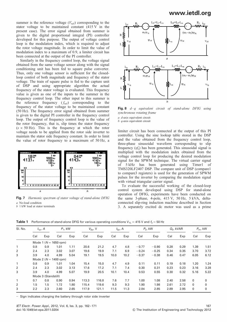
Similarly in the frequency control loop, the voltage signalobtained from the same voltage sensor along with the signalconditioning unit has been fed to square pulse converter.Thus, only one voltage sensor is sufficient for the closed-loop control of both magnitude and frequency of the statorvoltage. The train of square pulse is fed to the capture unitof DSP and using appropriate algorithm the actualfrequency of the stator voltage is evaluated. This frequencyvalue is given as one of the inputs to the summer in thefrequency control loop. The other input to this summer isthe reference frequency ( fref) corresponding to thefrequency of the stator voltage to be maintained constant(50 Hz). The frequency error signal obtained from summeris given to the digital PI controller in the frequency controlloop. The output of frequency control loop is the value ofthe rotor frequency, that is, slip times the stator frequency(s × 50 Hz). This is the frequency at which the rotorvoltage needs to be applied from the rotor side inverter tomaintain the stator side frequency constant. In order to limitthe value of rotor frequency to a maximum of 50 Hz, a
Fig. 7 Harmonic spectrum of stator voltage of stand-alone DFIG
a No-load conditionb 1 kW load at stator terminals
IET Electr. Power Appl., 2012, Vol. 6, Iss. 3, pp. 162–171doi: 10.1049/iet-epa.2011.0204
limiter circuit has been connected at the output of this PIcontroller. Using the sine lookup table stored in the DSPand the value obtained from the frequency control loop,three-phase sinusoidal waveform corresponding to slipfrequency (sfs) has been generated. This sinusoidal signal ismultiplied with the modulation index obtained from thevoltage control loop for producing the desired modulationsignal for the SPWM technique. The virtual carrier signalof 5 kHz has been generated using Timer1 ofTMS320LF2407 DSP. The compare unit of DSP (compare1to compare3 registers) is used for the generation of SPWMpulses for the inverter by comparing the modulation signalwith virtual triangular carrier signal.
To evaluate the successful working of the closed-loopcontrol system developed using DSP for stand-aloneoperation of DFIG, experiments have been conducted onthe same 3-phase, 4-pole, 415 V, 50 Hz, 5 kVA, delta-connected slip-ring induction machine described in Section3. A separately excited dc motor was used as a prime
Fig. 8 d–q equivalent circuit of stand-alone DFIG usingsynchronous rotating frame
a d-axis equivalent circuitb q-axis equivalent circuit
Table 1 Performance of stand-alone DFIG for various operating conditions V1L ¼ 415 V and fs ¼ 50 Hz
Sl. No. I1p, A P1, kW V2p, V I2p, A P2, kW Q2, kVAR Pm, kW
Cal Exp Cal Exp Cal Exp Cal Exp Cal Exp Cal Exp Cal Exp
Mode 1 (N ¼ 1650 rpm)
1 0.8 0.9 1.01 1.11 20.6 21.2 4.7 4.8 20.77 20.90 0.28 0.29 1.39 1.51
2 2.4 2.3 3.02 3.07 19.6 19.9 7.1 6.9 20.24 20.25 0.34 0.35 3.70 3.72
3 3.9 4.0 4.99 5.04 19.1 19.5 10.0 10.2 20.37 20.38 0.46 0.47 6.05 6.12
Mode 2 (N ¼ 1400 rpm)
1 0.8 0.9 1.01 1.04 15.4 15.0 4.7 4.9 0.11 0.11 0.19 0.18 1.20 1.24
2 2.4 2.3 3.02 3.13 17.6 17.2 7.1 7.4 0.30 0.31 0.23 0.23 3.16 3.28
3 3.9 4.0 4.99 5.07 19.9 20.5 10.1 10.4 0.53 0.55 0.30 0.32 5.16 5.22
Mode 3 (Standstill)
1 0.7 0.8 0.90 0.94 113.3 116.8 7.6 7.7 1.00 1.08 2.40 2.58 0 0
2 1.5 1.5 1.72 1.80 115.4 119.6 9.3 9.3 1.90 1.98 2.61 2.72 0 0
3 2.2 2.3 2.60 2.65 117.9 121.1 11.5 11.3 2.84 2.85 2.89 2.95 0 0
2 Sign indicates charging the battery through rotor side inverter
167
& The Institution of Engineering and Technology 2012

www.ietdl.org
Fig. 10 Dynamic response to step change in load N ¼ 1450 rpm and tlc: instant at which load change initiated
a From no-load to 1 kW loadb From 1 to 2 kW loadc From 2 to 1 kW loadFor experimental waveforms: stator voltage axis: 590 V/div, stator current axis: 6.4 A/div, rotor current axis: 17 A/div, speed axis: 2130 rpm/div, time axis:200 ms/div
Fig. 9 Dynamic response of stator voltage N ¼ 1450 rpm and ti: instant of rotor voltage application
For experimental waveforms: Stator voltage axis: 590 V/div, Rotor current axis: 10 A/div, Actual and reference voltage axes: 4.88 V/div, Time axis: 200 ms/div
168 IET Electr. Power Appl., 2012, Vol. 6, Iss. 3, pp. 162–171
& The Institution of Engineering and Technology 2012 doi: 10.1049/iet-epa.2011.0204
www.ietdl.org
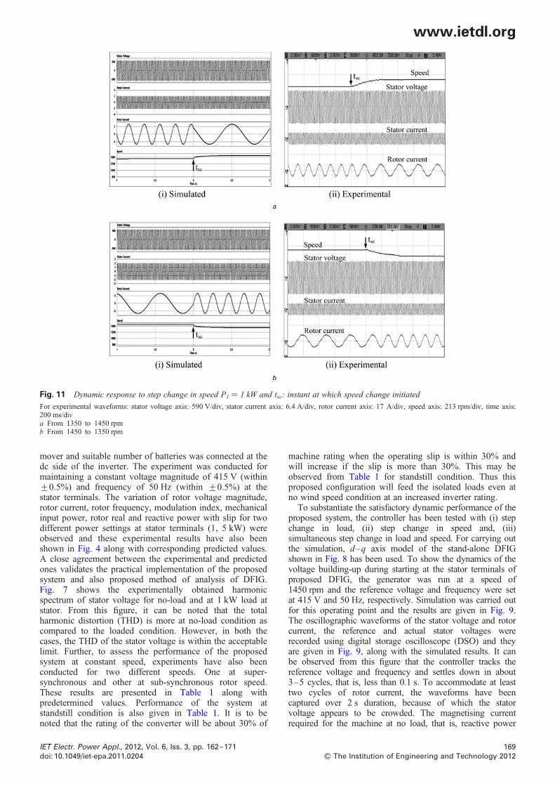
Fig. 11 Dynamic response to step change in speed P1 ¼ 1 kW and tsc: instant at which speed change initiated
For experimental waveforms: stator voltage axis: 590 V/div, stator current axis: 6.4 A/div, rotor current axis: 17 A/div, speed axis: 213 rpm/div, time axis:200 ms/diva From 1350 to 1450 rpmb From 1450 to 1350 rpm
mover and suitable number of batteries was connected at thedc side of the inverter. The experiment was conducted formaintaining a constant voltage magnitude of 415 V (within+0.5%) and frequency of 50 Hz (within +0.5%) at thestator terminals. The variation of rotor voltage magnitude,rotor current, rotor frequency, modulation index, mechanicalinput power, rotor real and reactive power with slip for twodifferent power settings at stator terminals (1, 5 kW) wereobserved and these experimental results have also beenshown in Fig. 4 along with corresponding predicted values.A close agreement between the experimental and predictedones validates the practical implementation of the proposedsystem and also proposed method of analysis of DFIG.Fig. 7 shows the experimentally obtained harmonicspectrum of stator voltage for no-load and at 1 kW load atstator. From this figure, it can be noted that the totalharmonic distortion (THD) is more at no-load condition ascompared to the loaded condition. However, in both thecases, the THD of the stator voltage is within the acceptablelimit. Further, to assess the performance of the proposedsystem at constant speed, experiments have also beenconducted for two different speeds. One at super-synchronous and other at sub-synchronous rotor speed.These results are presented in Table 1 along withpredetermined values. Performance of the system atstandstill condition is also given in Table 1. It is to benoted that the rating of the converter will be about 30% of
IET Electr. Power Appl., 2012, Vol. 6, Iss. 3, pp. 162–171doi: 10.1049/iet-epa.2011.0204
machine rating when the operating slip is within 30% andwill increase if the slip is more than 30%. This may beobserved from Table 1 for standstill condition. Thus thisproposed configuration will feed the isolated loads even atno wind speed condition at an increased inverter rating.
To substantiate the satisfactory dynamic performance of theproposed system, the controller has been tested with (i) stepchange in load, (ii) step change in speed and, (iii)simultaneous step change in load and speed. For carrying outthe simulation, d–q axis model of the stand-alone DFIGshown in Fig. 8 has been used. To show the dynamics of thevoltage building-up during starting at the stator terminals ofproposed DFIG, the generator was run at a speed of1450 rpm and the reference voltage and frequency were setat 415 V and 50 Hz, respectively. Simulation was carried outfor this operating point and the results are given in Fig. 9.The oscillographic waveforms of the stator voltage and rotorcurrent, the reference and actual stator voltages wererecorded using digital storage oscilloscope (DSO) and theyare given in Fig. 9, along with the simulated results. It canbe observed from this figure that the controller tracks thereference voltage and frequency and settles down in about3–5 cycles, that is, less than 0.1 s. To accommodate at leasttwo cycles of rotor current, the waveforms have beencaptured over 2 s duration, because of which the statorvoltage appears to be crowded. The magnetising currentrequired for the machine at no load, that is, reactive power
169
& The Institution of Engineering and Technology 2012

www.ietdl.org
Fig. 12 Dynamic response to simultaneous step change in load and speed tsl: instant at which speed and load change initiated simultaneously
a Speed change from 1200 to 1450 rpm, Load change from no-load to 5 kWb Speed change from 1450 to 1200 rpm, Load change from 5 kW to no-loadStator voltage axis: 1180 V/div, Stator current axis: 12.8 A/div, Rotor current axis: 17 A/div, Speed axis: 213 rpm/div, Time axis: 200 ms/div
requirement of the generator, is supplied by the rotor sideinverter. For this operating point, the rotor is fed with 13 V(0.11 modulation index) and the inverter supplies the rotorcurrent of 4.2 A. Experiments have been conducted for stepchange in the resistive load at stator terminals of thegenerator (a) from no-load to 1 kW load, (b) 1 kW load to2 kW load and (c) 2 kW load to 1 kW load and the responseof the controller was observed. The oscillographicwaveforms of stator voltage, stator current, rotor current andspeed for these operating points were recorded using DSOand they are presented in Fig. 10 along with the simulatedresults. It is to be noted that the inverter supplies 4.2 A at noload and this current increases to 4.7 A for 1 kW load and5.5 A for 2 kW load for maintaining the stator voltage at415 V, 50 Hz. However, stator current has been changed tomeet out this step change in load, which is also depicted inFig. 10. Here again the satisfactory performance of thecontroller was observed by tracking the voltage andfrequency at the set values within 3–5 cycles.
Fig. 11 illustrates the dynamic response of the system forstep change in speed, whereas the load at the stator is keptconstant at 1 kW. In the experimental set-up, the fieldcurrent of the separately excited dc motor was suddenlydecreased/increased for increasing/decreasing the rotorspeed of DFIG. Owing to the time constant of the prime-mover and generator, exact step change in speed could notbe obtained experimentally. From this figure, it can beobserved that (i) the stator voltage magnitude and frequencyare maintained constant at set values by the closed-loopcontroller, (ii) the frequency of rotor current is varieddepending upon the rotor speed as per (7). Further, therotor current magnitude is same for change in speed, butthe rotor voltage magnitude is varied depending on therotor speed, which is also given in Fig. 4a. Fig. 12illustrates the experimental results on the system forsimultaneous step change in the load and speed. Fig. 12agives step change in the resistive load from no-load tomaximum rating of the generator (5 kW) and speed of 1200to 1450 rpm. It has been observed that for this large stepchange in operating conditions namely load and speed, thecontroller takes about 0.3 s for tracking the voltage andfrequency at set values. Similar response has been observedwhen the load on the generator was suddenly removed fromits rated value and the speed also changed from 1450 to1200 rpm.
170
& The Institution of Engineering and Technology 2012
5 Conclusions
This paper has attempted a stand-alone DFIG which utilisesonly one SPWM converter in the rotor circuit along withthe battery. The parameter insensitive closed-loop controlscheme proposed in the paper for maintaining the statorvoltage magnitude and frequency at set value has beenimplemented using TMS320LF2407A DSP. Methods havealso been developed for the predetermination of steady-stateand dynamic performance of the system. Extensiveexperimentation has been carried out and the resultsobtained on a generator–inverter-battery system togetherwith the developed controller and the various simulatedwaveforms demonstrate the working of the controller andvalidity of the proposed analysis.
It has been shown that for smoothing out the intermittentpower from the wind, the DFIG operates in super-synchronous and sub-synchronous rotor speeds leading tocharging/discharging the batteries depending upon theexcess/deficit wind power. The excess energy available inthe wind is used to charge the batteries instead ofdissipating it into the dump loads. The stored energyavailable in the battery is used for supplying the isolatedloads even at no wind speed. These aspects are clearlybrought out in the paper. Thus, the constant voltage andconstant frequency operation of DFIG along with batterystorage arrangement makes the proposed system attractivefor supplying the isolated loads from wind energy.
6 Acknowledgments
The authors wish to thank the authorities of the NationalInstitute of Technology, Tiruchirappalli, India for all thefacilities provided for carrying out the experimental andsimulation work for the preparation of this paper. Theauthors also wish to thank NaMPET, an initiative of DIT,Govt. of India for providing fund for infrastructuredevelopment of Power Converters Research Laboratory, inwhich the experiments have been carried out.
7 References
1 Tazil, M., Kumar, V., Bansal, R.C., et al.: ‘Three-phase doubly fedinduction generators: an overview’, IET Electr. Power Appl., 2010, 4,(2), pp. 75–89
IET Electr. Power Appl., 2012, Vol. 6, Iss. 3, pp. 162–171doi: 10.1049/iet-epa.2011.0204

www.ietdl.org
2 Chen, Z., Guerrero, J.M., Blaabjerg, F.: ‘A review of the state of the artof power electronics for wind turbines’, IEEE Trans. Power Electron.,2009, 24, (8), pp. 1859–1875
3 Pena, R., Clare, J.C., Asher, G.M.: ‘A doubly fed induction generatorusing back-to-back PWM converters supplying an isolated load froma variable speed wind turbine’, IEE Proc. Electr. Power Appl., 1996,143, (5), pp. 380–387
4 Cardenas, R., Pena, R., Proboste, J., Asher, G., Clare, J.: ‘MRASobserver for sensorless control of standalone doubly fedinduction generators’, IEEE Trans. Energy Convers., 2005, 20, (4),pp. 710–718
5 Jain, A.K., Ranganathan, V.T.: ‘Wound rotor induction generator withsensorless control and integrated active filter for feeding nonlinearloads in a stand-alone grid’, IEEE Trans. Ind. Electron., 2008, 55, (1),pp. 218–228
6 Bhattacharya, T., Umanand, L.: ‘Rotor position estimator for stator flux-oriented sensorless control of slip ring induction machine’, IET Electr.Power Appl., 2009, 3, (1), pp. 67–76
7 Forchetti, D.G., Garcia, G.O., Valla, M.I.: ‘Adaptive observer forsensorless control of stand-alone doubly fed induction generator’,IEEE Trans. Ind. Electron., 2009, 56, (10), pp. 4174–4180
8 Iwanski, G., Koczara, W.: ‘DFIG-based power generation system withUPS function for variable-speed applications’, IEEE Trans. Ind.Electron., 2008, 55, (8), pp. 3047–3054
9 Fan, L., Yuvarajan, S., Kavasseri, R.: ‘Harmonic analysis of a DFIG fora wind energy conversion system’, IEEE Trans. Energy Convers., 2010,25, (1), pp. 181–190
IET Electr. Power Appl., 2012, Vol. 6, Iss. 3, pp. 162–171doi: 10.1049/iet-epa.2011.0204
10 Daido, T., Miura, Y., Ise, T., Sato, Y.: ‘A study on a start-up methodduring a blackout of a doubly-fed induction generator applied to gasengine cogeneration system’. Proc. IEEE ICPE &ECCE 2011, 30 May2011–3 June 2011, pp. 2051–2058
11 Mi, C., Filippa, M., Shen, J., Natarajan, N.: ‘Modeling and control of avariable-speed constant-frequency synchronous generator with brushlessexciter’, IEEE Trans. Ind. Appl., 2004, 40, (2), pp. 565–573
12 Ansel, A., Nasser, L., Robyns, B.: ‘Variable speed small hydro plantconnected to power grid or isolated loads’. Proc. IEEE EPE-PEMC2006, August 2006, pp. 2064–2069
13 Pena, R., Cardenas, R., Proboste, J., Clare, J., Asher, G.: ‘Wind–dieselgeneration using doubly fed induction machines’, IEEE Trans. EnergyConvers., 2008, 23, (1), pp. 202–214
14 Arul Daniel, S., Ammasai Gounden, N.: ‘A novel hybrid isolatedgenerating system based on PV fed inverter-assisted wind-driveninduction fenerators’, IEEE Trans. Energy Convers., 2004, 19, (2),pp. 416–422
15 Yang, T.C.: ‘Initial study of using rechargeable batteries in wind powergeneration with variable speed induction generators’, IET Renew. PowerGener., 2008, 2, (2), pp. 89–101
16 Karthigaivel, R., Kumaresan, N., Subbiah, M.: ‘Analysis and controlof self-excited induction generator-converter systems for batterycharging applications’, IET Electr. Power Appl., 2011, 5, (2),pp. 247–257
17 Chan, T.F., Nigim, K.A., Lai, L.L.: ‘Voltage and frequency controlof self-excited slip-ring induction generators’, IEEE Trans. EnergyConvers., 2004, 19, (1), pp. 81–87
171
& The Institution of Engineering and Technology 2012