Operating Manual Series X - Gardner Denver
37
M/102/0307/GB Series X Stainless Steel Positive Displacement Rotary Lobe Pumps Operating Manual
Transcript of Operating Manual Series X - Gardner Denver

M/102/0307/GB
Series X
Stainless Steel Positive Displacement Rotary Lobe Pumps
Operating Manual

10

The information contained herein is correct at the time of issue but may be subject to change without prior notice.
11
Table of contents
1. General description ........................................................................... 12
1.1 General description ...................................................................... 12
2. Safety .................................................................................................. 13
2.1 Important information .................................................................... 13
2.2 Warning signs ............................................................................... 13
2.3 Safety precautions ........................................................................ 14
3. Installation .......................................................................................... 15
3.1 Unpacking, Handling and Storage ................................................ 15
3.2 System design and installation ...................................................... 16
3.3 Flushed seal arrangements and pre-start up checks ................... 19
4. Maintenance ....................................................................................... 21
4.1 Cleaning in place (CIP) ................................................................. 21
4.2 Maintenance schedule .................................................................. 22
4.3 Disassembly .................................................................................. 23
4.4 Assembly ...................................................................................... 26
4.5 Primary seals removal and fitting .................................................. 32
4.6 Troubleshooting ............................................................................ 35
5. Technical data .................................................................................... 36
5.1 Technical data ............................................................................... 36
6. Parts list .............................................................................................. 38
6.1 X1 - 3 Pump Range ...................................................................... 38
6.2 X4 Pump Range ............................................................................ 40
6.3 X5 - 7 Pump Range - Vertically Ported ......................................... 42
7. Appendix
7.1 Appendix A ................................................................................... 44
7.2 Appendix B ................................................................................... 45
12
1.1 General description 1. General description
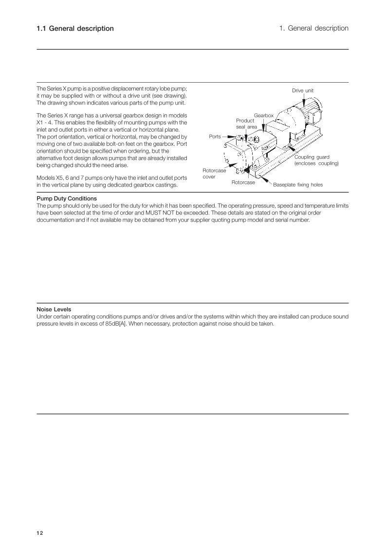
The Series X pump is a positive displacement rotary lobe pump;
it may be supplied with or without a drive unit (see drawing).
The drawing shown indicates various parts of the pump unit.
The Series X range has a universal gearbox design in models
X1 - 4. This enables the flexibility of mounting pumps with the
inlet and outlet ports in either a vertical or horizontal plane.
The port orientation, vertical or horizontal, may be changed by
moving one of two available bolt-on feet on the gearbox. Port
orientation should be specified when ordering, but the
alternative foot design allows pumps that are already installed
being changed should the need arise.
Models X5, 6 and 7 pumps only have the inlet and outlet ports
in the vertical plane by using dedicated gearbox castings. Baseplate fixing holes
Coupling guard
(encloses coupling)
Rotorcase
Rotorcase
cover
Ports
Product
seal area
Gearbox
Drive unit
Pump Duty Conditions
The pump should only be used for the duty for which it has been specified. The operating pressure, speed and temperature limits
have been selected at the time of order and MUST NOT be exceeded. These details are stated on the original order
documentation and if not available may be obtained from your supplier quoting pump model and serial number.
Noise Levels
Under certain operating conditions pumps and/or drives and/or the systems within which they are installed can produce sound
pressure levels in excess of 85dB[A]. When necessary, protection against noise should be taken.
13
2. Safety 2.1 Important information2.2 Warning signs
Always read the manual before using the pump!
WARNING!
Indicates that special procedures must be followed to avoid severe personal injury.
CAUTION!
Indicates that special procedures must be followed to avoid damage to the pump.
NOTE!
Indicates important information to simplify or clarify practices.
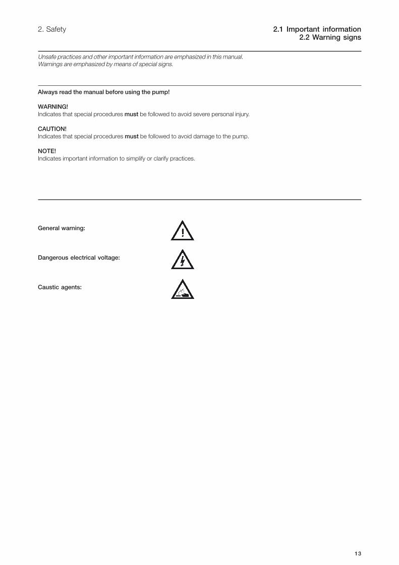
General warning:
Dangerous electrical voltage:
Caustic agents:
Unsafe practices and other important information are emphasized in this manual.
Warnings are emphasized by means of special signs.

14
2.3 Safety precautions 2. Safety
All warnings in the manual are summarised on this page.
Pay special attention to the instructions below so that severe personal injury or damage to the pump are avoided.
Installation
- AlwaysAlwaysAlwaysAlwaysAlways observe the technical data (see chapter 5).
- NeverNeverNeverNeverNever start in the wrong direction of rotation with liquid in the pump.
- NeverNeverNeverNeverNever put your hands or fingers inside the port connections or anywhere close to rotating
shafts.
The pump must must must must must be electrically connected by authorised personnel (see the motor instructions
supplied with the drive unit).
Operation
- AlwaysAlwaysAlwaysAlwaysAlways observe the technical data (see chapter 5).
- NeverNeverNeverNeverNever touch the pump or the pipelines when pumping hot liquids or when sterilising.
- NeverNeverNeverNeverNever stand on the pump or pipelines.
- NeverNeverNeverNeverNever run the pump with both the suction side and the pressure side blocked.
- NeverNeverNeverNeverNever put your hands or fingers inside the port connections or anywhere close to rotating
shafts.
OnlyOnlyOnlyOnlyOnly handle toxic and acidic liquids in accordance with their manufacturers instructions and
recommendations.
Maintenance
- AlwaysAlwaysAlwaysAlwaysAlways observe the technical data (see chapter 5).
- The pump must nevernevernevernevernever be serviced when hot.
- The pump and the pipelines must nevernevernevernevernever be pressurised when the pump is being serviced.
- NeverNeverNeverNeverNever put your hands or fingers inside the port connections or anywhere close to rotating
shafts.
AlwaysAlwaysAlwaysAlwaysAlways disconnect the power supply when the pump is being serviced.
15
3. Installation 3.1 Unpacking, Handling and Storage
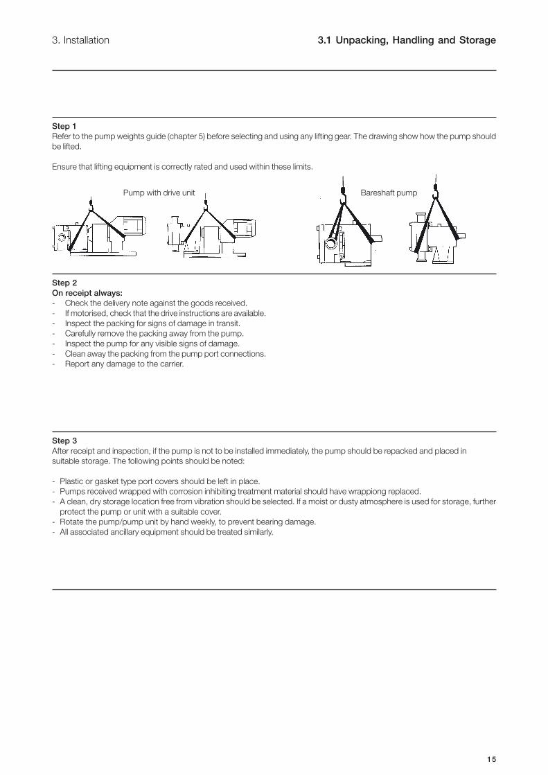
Step 1
Refer to the pump weights guide (chapter 5) before selecting and using any lifting gear. The drawing show how the pump should
be lifted.
Ensure that lifting equipment is correctly rated and used within these limits.
Bareshaft pumpPump with drive unit
Step 2
On receipt always:
- Check the delivery note against the goods received.
- If motorised, check that the drive instructions are available.
- Inspect the packing for signs of damage in transit.
- Carefully remove the packing away from the pump.
- Inspect the pump for any visible signs of damage.
- Clean away the packing from the pump port connections.
- Report any damage to the carrier.
Step 3
After receipt and inspection, if the pump is not to be installed immediately, the pump should be repacked and placed in
suitable storage. The following points should be noted:
- Plastic or gasket type port covers should be left in place.
- Pumps received wrapped with corrosion inhibiting treatment material should have wrappiong replaced.
- A clean, dry storage location free from vibration should be selected. If a moist or dusty atmosphere is used for storage, further
protect the pump or unit with a suitable cover.
- Rotate the pump/pump unit by hand weekly, to prevent bearing damage.
- All associated ancillary equipment should be treated similarly.
16
3.2 System design and installation 3. Installation
Step 1
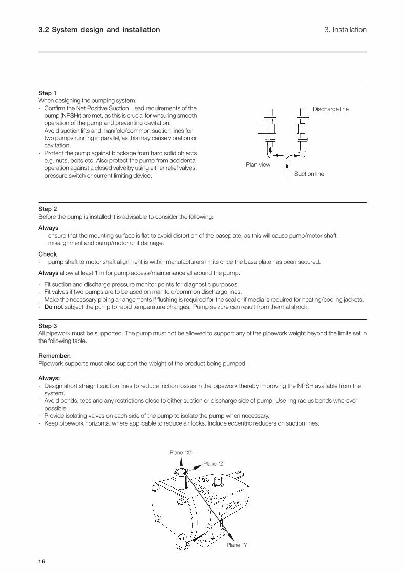
When designing the pumping system:
- Confirm the Net Positive Suction Head requirements of the
pump (NPSHr) are met, as this is crucial for wnsuring smooth
operation of the pump and preventing cavitation.
- Avoid suction lifts and manifold/common suction lines for
two pumps running in parallel, as this may cause vibration or
cavitation.
- Protect the pump against blockage from hard solid objects
e.g. nuts, bolts etc. Also protect the pump from accidental
operation against a closed valve by using either relief valves,
pressure switch or current limiting device.
Discharge line
Plan view
Suction line
Step 2
Before the pump is installed it is advisable to consider the following:
Always
- ensure that the mounting surface is flat to avoid distortion of the baseplate, as this will cause pump/motor shaft
misalignment and pump/motor unit damage.
Check
- pump shaft to motor shaft alignment is within manufacturers limits once the base plate has been secured.
Always allow at least 1 m for pump access/maintenance all around the pump.
- Fit suction and discharge pressure monitor points for diagnostic purposes.
- Fit valves if two pumps are to be used on manifold/common discharge lines.
- Make the necessary piping arrangements if flushing is required for the seal or if media is required for heating/cooling jackets.
- Do not subject the pump to rapid temperature changes. Pump seizure can result from thermal shock.
Step 3
All pipework must be supported. The pump must not be allowed to support any of the pipework weight beyond the limits set in
the following table.
Remember:
Pipework supports must also support the weight of the product being pumped.
Always:
- Design short straight suction lines to reduce friction losses in the pipework thereby improving the NPSH available from the
system.
- Avoid bends, tees and any restrictions close to either suction or discharge side of pump. Use ling radius bends wherever
possible.
- Provide isolating valves on each side of the pump to isolate the pump when necessary.
- Keep pipework horizontal where applicable to reduce air locks. Include eccentric reducers on suction lines.
Plane ‘X’
Plane ‘Z’
Plane ‘Y’

17
3. Installation 3.2 System design and installation
Step 3 - continued
Table of Maximum Forces and Moments
Step 4
The direction of flow is dictated by the direction of rotation of the drive shaft. Reversing the direction of rotation will reverse the
flow direction.
For oil quantities required, please see technical data (chapter 5).
Pump Forces Moments
Model FZ FY FX EF MZ MY MX EM
X1 Forces N 80 60 70 120
lbf 18 13 16 27
Moments Nm 30 30 30 50
lbft 22 22 22 37
X2 Forces N 125 100 110 190
lbf 28 22 25 43
Moments Nm 60 70 75 115
lbft 44 52 55 85
X3/4 Forces N 165 135 150 260
lbf 37 30 34 58
Moments Nm 100 115 140 205
lbft 74 85 103 151
X5/6 Forces N 300 250 250 460
lbf 67 56 56 103
Moments Nm 125 145 175 260
lbft 92 107 129 192
X7 Forces N 380 320 320 590
lbf 85 72 72 133
Moments Nm 165 190 230 340
lbft 122 140 170 251
DischargeSuction Discharge
SuctionDischarge DischargeSuction
Suction
18
3.2 System design and installation 3. Installation
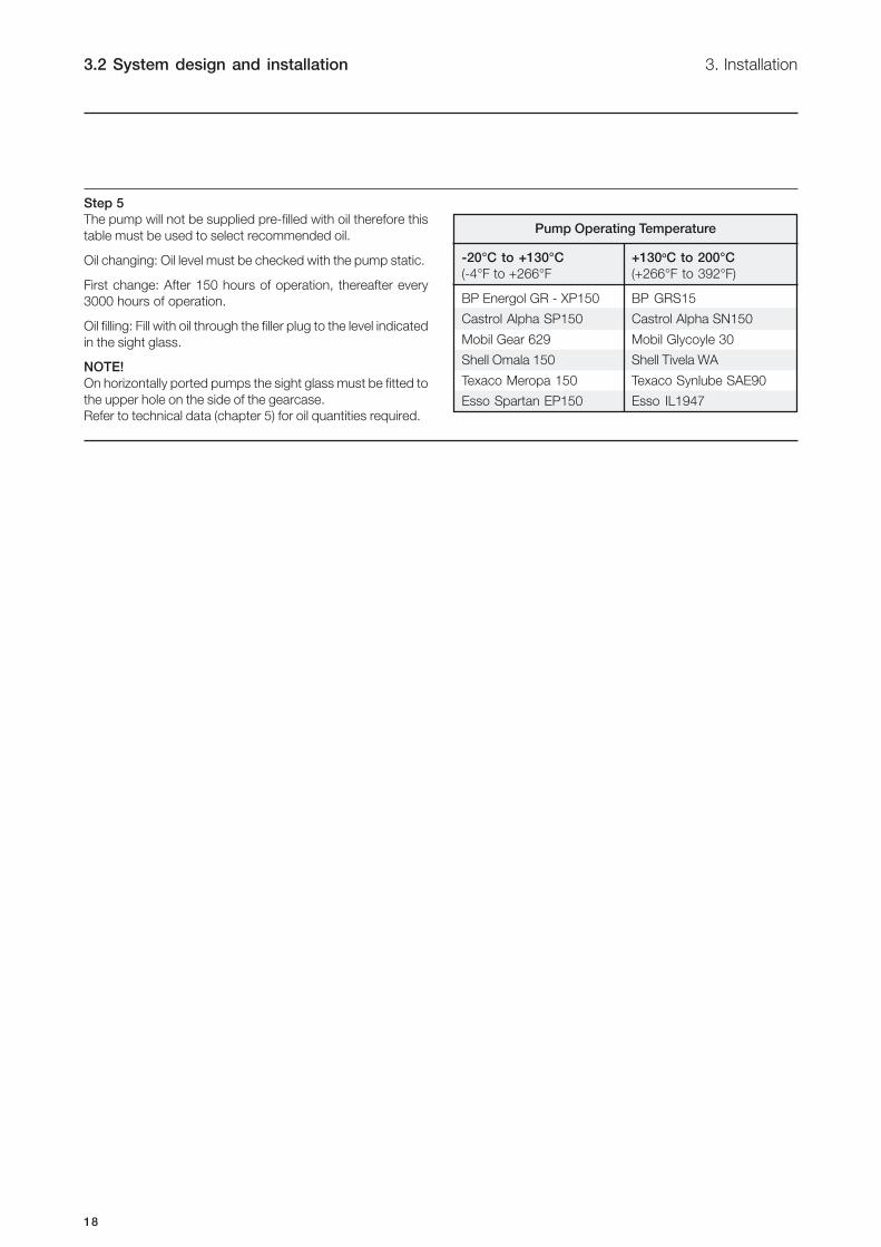
Step 5
The pump will not be supplied pre-filled with oil therefore this
table must be used to select recommended oil.
Oil changing: Oil level must be checked with the pump static.
First change: After 150 hours of operation, thereafter every
3000 hours of operation.
Oil filling: Fill with oil through the filler plug to the level indicated
in the sight glass.
NOTE!
On horizontally ported pumps the sight glass must be fitted to
the upper hole on the side of the gearcase.
Refer to technical data (chapter 5) for oil quantities required.
Pump Operating Temperature
-20°C to +130°C +130oC to 200°C
(-4°F to +266°F (+266°F to 392°F)
BP Energol GR - XP150 BP GRS15
Castrol Alpha SP150 Castrol Alpha SN150
Mobil Gear 629 Mobil Glycoyle 30
Shell Omala 150 Shell Tivela WA
Texaco Meropa 150 Texaco Synlube SAE90
Esso Spartan EP150 Esso IL1947

19
3. Installation 3.3 Flushed seal arrangementsand pre-start up checks
Step 1
A flushed seal arrangement is fitted in order to cool or clean the seal area.
It is important that:
- The flush is correctly connected (see below).
- A compatible flushing fluid is used and supplied at the correct pressure and flow rate.
- The flush is turned on at the same time/prior to starting the pump, and turned off at the same time/after stopping the
pump.
Step 2
Connecting the flush
The following equipment is strongly recommended when using a flushing system:
- Control valve and pressure gauge, to enable the correct flushing pressure to be obtained and monitored.
- Isolation valve and check valve, so that the flush can be turned off, and to stop any unwanted substances flowing in
the wrong direction.
- A method of visibly indicating flushing fluid flow.
Step 3
Flusing pipework
This suggested arrangement is for single mechanical seals. If
the pump is fitted with double mechanical seals or packed
glands the pressure gauges and control valves should be
fitted on the outlet side of the system.
20
3.3 Flushing seal arrangementand pre-start up checks
3. Installation
Step 4
Flushing fluid
The choice of flushing fluid is dependent upon the fluid being pumped and duty conditions i.e. pressure and temperature. Usually
water is used for cooling or flushing water soluble products. For advice on selecting a suitable flushing fluid please contact pump
supplier.
Step 5
Flusing pressure and flow rate
Single mechanical seal 0.5 bar (7 psi) maximum. Any further increase in pressure will result in lip seal failure.
Double mechanical seal/flushed packed gland 1.0 bar (14 psi) higher pressure than the discharge of the pump. If the discharge
pressure fluctuates set the pressure to suit maximum condition.
The flushing flow rate must be adequate to ensure that the temperature limitation of the seals is not exceeded. Contact your
pump supplier for further information on the recommended flow.
Step 6
Pre-start up checks
- Check the pipework system has been purged to remove debris.
- Check all obstructions have been removed from pipework and pump.
- Check pump connections and pipework joints are tight.
- Check lubrication levels are correct.
- Check seal flushing is connected if applicable.
- Check all safety guards are in place.

21
4. Maintenance 4.1 Cleaning in place (CIP)
The pump can be manually cleaned or cleaned in place (CIP). The following is an example of a typical CIP procedure. However
specific advice for each application should be sought from the pump supplier.
Typical CIP procedure
1. Flush through the system with cold water or bore water (6°) (43°F).
2. Run hot caustic soda (70-80°C) (158-176°F) at 2.5% dilution through the system for 20-30 minutes.
3. Final flush through with cold water again.
Warnings
- NeverNeverNeverNeverNever touch the pump or the pipelines as they will be extremely hot!hot!hot!hot!hot!
- Do not Do not Do not Do not Do not subject the pump to rapid temperature changes during CIP procedures, as pump
seizure can result from thermal shock.A suitable by-pass is recommended.
- AlwaysAlwaysAlwaysAlwaysAlways rinse well with clean water after using a cleaning agent.
- AlwaysAlwaysAlwaysAlwaysAlways use rubber gloves and protective goggles when handling caustic agents.
- AlwaysAlwaysAlwaysAlwaysAlways store/discharge cleaning agents in accordance with current rules/directives.
22
4.2 Maintenance schedule 4. Maintenance
It is advisable to install pressure gauges on both sides of the pump so that any problems within the pump/pipework can be
monitored.
Maintenance schedule
Your weekly schedule should include:
- Checking the oil level in the gearcase with the pump stationary.
- Checking the seals for leakage and replacing as necessary.
- Checking the oil seals for leakage.
- Check pumping pressures.
In certain operational circumstances the pump will pose a thermal hazard and as such should not be touched during operation.
After shutdown the pump unit should be allowed time to cool.
Oil should be changed every 3000 hours of operation or a period of 2 years, whichever is the soonest.
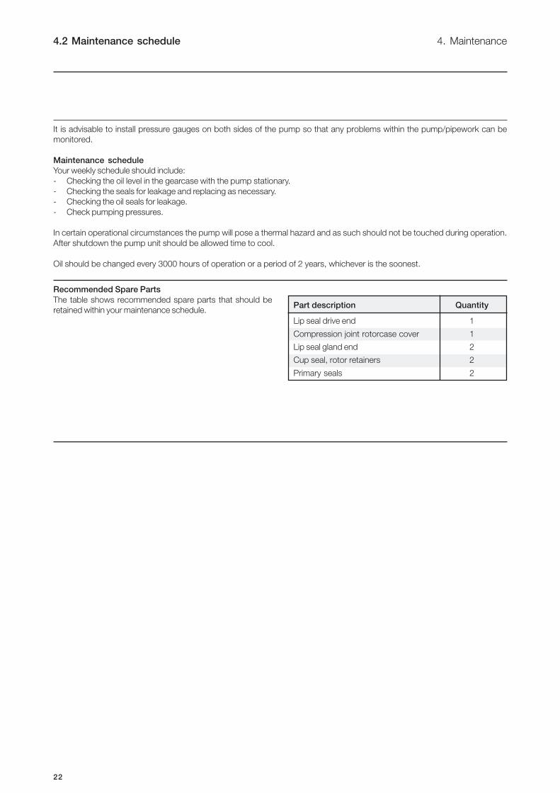
Part description Quantity
Lip seal drive end 1
Compression joint rotorcase cover 1
Lip seal gland end 2
Cup seal, rotor retainers 2
Primary seals 2
Recommended Spare Parts
The table shows recommended spare parts that should be
retained within your maintenance schedule.

23
4. Maintenance 4.3 Disassembly
Step 1
Before disassembling the pump refer to safety
precautions. See exploded view drawings (chapter 6).
Removing rotorcase cover.
Remove rotorcase cover nuts (13) and cover (12).
Step 2
Removing rotors
Insert a plastic/wooden block between the two rotors (17)
to stop them turning.
Plastic or
wooden block
Step 3
Remove rotor retainer (22) and rotors. A rotor retainer
removal tool (supplied with all new pumps) is used for this
purpose by sliding the tool into the rotor retainer slot and
turning in an anti-clockwise direction.
Rotor retainer
removal tool
Step 4
Removing static seal components
Please see section 4.5 for seal removal.

24
4.3 Disassembly 4. Maintenance
Step 7
Removing seal retainers
1. Remove screws (15).
2. Then remove seal retainers (14) - as a liquid sealant has
been used a lever may be required to remove retainers.
3. The lip seals (16) can be removed using a screwdriver/
lever once the seal retainers are removed. It is essential to
renew the lip seals and it is recommended that new
gaskets or sealant be used prior to reassembly.
Step 8
Removing Gearcase Cover
1. Remove screws (6).
2. Remove gearcase cover (5) after breaking the gasket seal
then press out the lip seal (7). It is essential to renew the lip
seal prior to reassembly.
Step 5
Removing rotorcase
1. For flushed mechanical seal arrangements, remove the seal
housing retaining nuts and ease the seal housing from the
rotorcase.
2. Remove the rotorcase retaining nuts (4) and washers (4A).
3. Tap both sides of the rotorcase (9) with a soft mallet.
4. The rotorcase must not be allowed to drop onto the shafts
(24 and 25) during the removal process.
5. Shims (8) should not be removed unless rotor clearances
require resetting.
Step 6
Draining pump lubrication
1. Place a tray under the gearcase to collect the waste
lubricating oil.
2. Remove the lower drain plug (45) at the side of the gearcase
(1).
25
4. Maintenance 4.3 Disassembly
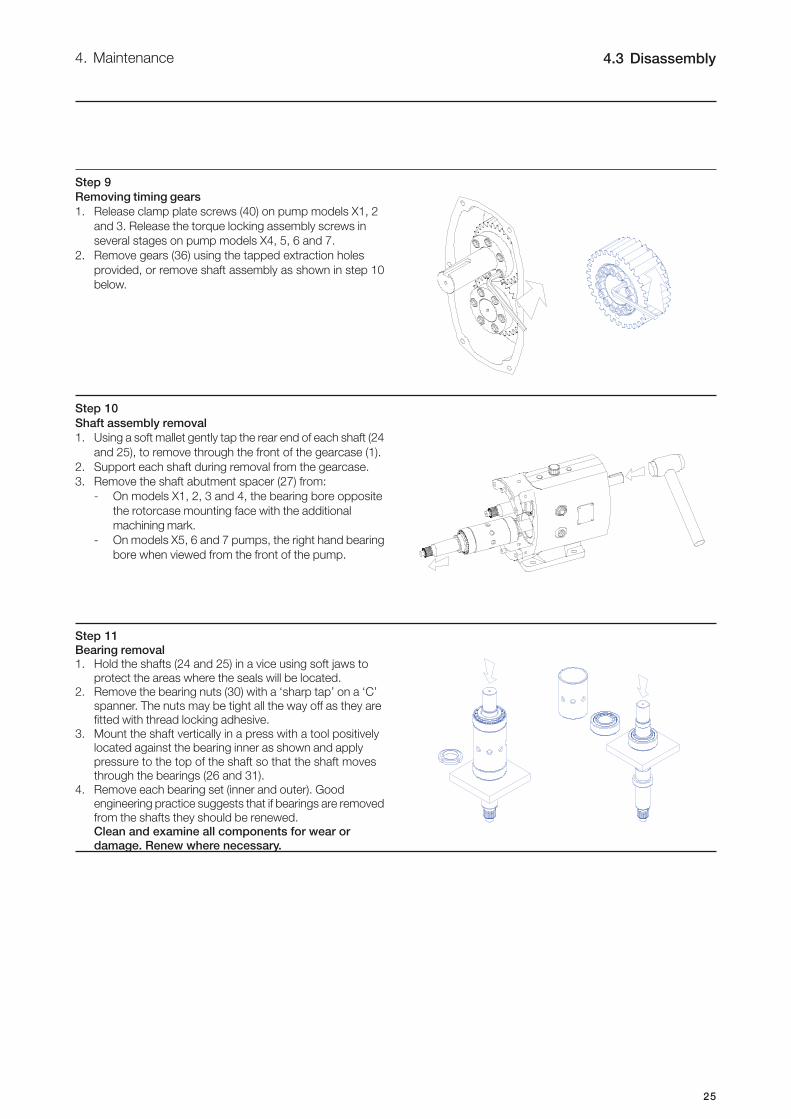
Step 9
Removing timing gears
1. Release clamp plate screws (40) on pump models X1, 2
and 3. Release the torque locking assembly screws in
several stages on pump models X4, 5, 6 and 7.
2. Remove gears (36) using the tapped extraction holes
provided, or remove shaft assembly as shown in step 10
below.
Step 10
Shaft assembly removal
1. Using a soft mallet gently tap the rear end of each shaft (24
and 25), to remove through the front of the gearcase (1).
2. Support each shaft during removal from the gearcase.
3. Remove the shaft abutment spacer (27) from:
- On models X1, 2, 3 and 4, the bearing bore opposite
the rotorcase mounting face with the additional
machining mark.
- On models X5, 6 and 7 pumps, the right hand bearing
bore when viewed from the front of the pump.
Step 11
Bearing removal1. Hold the shafts (24 and 25) in a vice using soft jaws to
protect the areas where the seals will be located.2. Remove the bearing nuts (30) with a ‘sharp tap’ on a ‘C’
spanner. The nuts may be tight all the way off as they arefitted with thread locking adhesive.
3. Mount the shaft vertically in a press with a tool positivelylocated against the bearing inner as shown and apply
pressure to the top of the shaft so that the shaft movesthrough the bearings (26 and 31).
4. Remove each bearing set (inner and outer). Goodengineering practice suggests that if bearings are removed
from the shafts they should be renewed.Clean and examine all components for wear or
damage. Renew where necessary.
26
4.4 Assembly 4. Maintenance
4.4.1 Fitting bearings to shafts
Take care not to damage shaft surfaces, in particular where the seals will be located.
Ensure all fasteings are tightened to torque settings as shown in Technical Data (chapter 5).
On models X1, 2 and 3 pumps, bearings do not require heating. For models X4, 5, 6 and 7 pumps, heat the bearing inner cones
to 110°C (230°F).
Do not use any form of live flame when heating, as this will damage bearings.
Step 1
Position shaft (24 and 25) vertically in a vice using soft jaws and apply anti-seize compound to the bearing diameters.
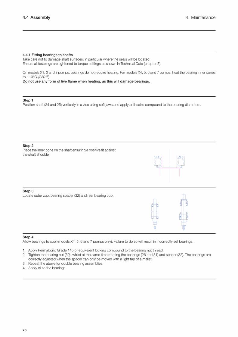
Step 2
Place the inner cone on the shaft ensuring a positive fit against
the shaft shoulder.
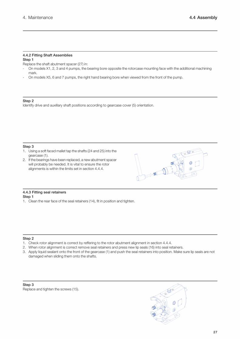
Step 3
Locate outer cup, bearing spacer (32) and rear bearing cup.
Step 4
Allow bearings to cool (models X4, 5, 6 and 7 pumps only). Failure to do so will result in incorrectly set bearings.
1. Apply Permabond Grade 145 or equivalent locking compound to the bearing nut thread.
2. Tighten the bearing nut (30), whilst at the same time rotating the bearings (26 and 31) and spacer (32). The bearings are
correctly adjusted when the spacer can only be moved with a light tap of a mallet.
3. Repeat the above for double bearing assemblies.
4. Apply oil to the bearings.
27
4. Maintenance 4.4 Assembly
4.4.2 Fitting Shaft Assemblies
Step 1
Replace the shaft abutment spacer (27) in:
- On models X1, 2, 3 and 4 pumps, the bearing bore opposite the rotorcase mounting face with the additional machining
mark.
- On models X5, 6 and 7 pumps, the right hand bearing bore when viewed from the front of the pump.
Step 2
Identify drive and auxillary shaft positions according to gearcase cover (5) orientation.
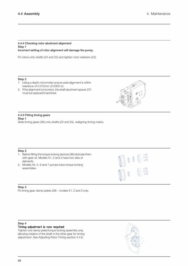
Step 3
1. Using a soft faced mallet tap the shafts (24 and 25) into the
gearcase (1).
2. If the bearings have been replaced, a new abutment spacer
will probably be needed. It is vital to ensure the rotor
alignments is within the limits set in section 4.4.4.
4.4.3 Fitting seal retainers
Step 1
1. Clean the rear face of the seal retainers (14), fit in position and tighten.
Step 3
Replace and tighten the screws (15).
Step 2
1. Check rotor alignment is correct by reffering to the rotor abutment alignment in section 4.4.4.
2. When rotor alignment is correct remove seal retainers and press new lip seals (16) into seal retainers.
3. Apply liquid sealant onto the front of the gearcase (1) and push the seal retainers into position. Make sure lip seals are not
damaged when sliding them onto the shafts.
28
4. Maintenance4.4 Assembly
4.4.5 Fitting timing gears
Step 1
Slide timing gears (36) onto shafts (24 and 25), realigning timing marks.
Step 4
Timing adjustment is now required:Timing adjustment is now required:Timing adjustment is now required:Timing adjustment is now required:Timing adjustment is now required:
Tighten one clamp plate/torque locking assembly only,
allowing rotation of the shaft in the other gear for timing
adjustment. See Adjusting Rotor Timing section 4.4.6.
4.4.4 Checking rotor abutment alignment
Step 1
Incorrect setting of rotor alignment will damage the pump.
Fit rotors onto shafts (24 and 25) and tighten rotor retainers (22).
Step 2
1. Using a depth micrometer ensure axial alignment is within
tolerance of 0.012mm (0.0005 in).
2. If the alignment is incorrect, the shaft abutment spacer (27)
must be replaced/machined.
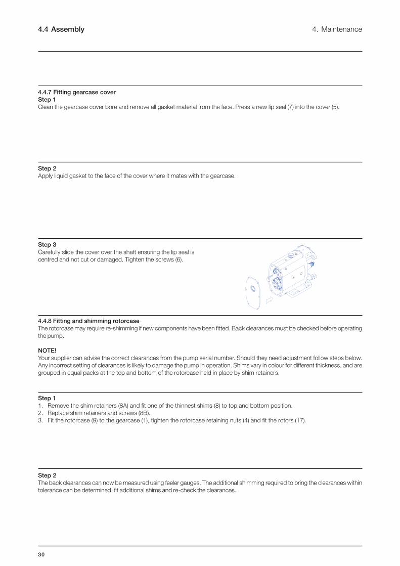
Step 2
1. Before fitting the torque locking devices (38) lubricate them
with gear oil. Models X1, 2 and 3 have two sets of
elements.
2. Models X4, 5, 6 and 7 pumps have torque locking
assemblies.
Step 3
Fit timing gear clamp plates (39) - models X1, 2 and 3 only.

29
4.4 Assembly4. Maintenance
Step 2
Locate one rotor (17) on to the drive shaft (24) with the dimple
at the top. Turn the rotor through 45°. Fit the second rotor on
to the auxillary shaft (25) with its dimple at the top as shown.
Step 3
Turn the shaft so that the rotors are in the new positions as
shown.
Step 4
Using feeler gauges measure between the points indicated,
turning the shaft as required.
Step 5
If the measurement points are unequal tap the rotor which is on the free turning shaft until equal measurement through 8 points is
achieved.
Step 6
Tighten the torque locking assemblies or clamp plate screws. Confirm timing is still correct. Remove the rotors.
Dimples
4.4.6 Adjusting rotor timing
Step 1
If the rotor timing requires adjustment (and assuming the pump has not yet been re-built), it is important to establish the cause for
the rotors mistiming before proceeding.
To allow timing adjustment ensure that one shaft is able to rotate within the torque locking assembly/element. The other torque
locking assembly/element should be tightened to the recommended torque.
30
Step 2
The back clearances can now be measured using feeler gauges. The additional shimming required to bring the clearances within
tolerance can be determined, fit additional shims and re-check the clearances.
4. Maintenance4.4 Assembly
Step 2
Apply liquid gasket to the face of the cover where it mates with the gearcase.
Step 3
Carefully slide the cover over the shaft ensuring the lip seal is
centred and not cut or damaged. Tighten the screws (6).
4.4.8 Fitting and shimming rotorcase
The rotorcase may require re-shimming if new components have been fitted. Back clearances must be checked before operating
the pump.
NOTE!
Your supplier can advise the correct clearances from the pump serial number. Should they need adjustment follow steps below.
Any incorrect setting of clearances is likely to damage the pump in operation. Shims vary in colour for different thickness, and are
grouped in equal packs at the top and bottom of the rotorcase held in place by shim retainers.
4.4.7 Fitting gearcase cover
Step 1
Clean the gearcase cover bore and remove all gasket material from the face. Press a new lip seal (7) into the cover (5).
Step 1
1. Remove the shim retainers (8A) and fit one of the thinnest shims (8) to top and bottom position.
2. Replace shim retainers and screws (8B).
3. Fit the rotorcase (9) to the gearcase (1), tighten the rotorcase retaining nuts (4) and fit the rotors (17).

31
4.4 Assembly4. Maintenance
4.4.9 Fitting primary seals
Step 1
Refer to section 4.5 for seal fitting instructions.
4.4.10 Fitting rotors
Step 1
If fitted, carefully slide the O rings (18) over the shaft spline until
they fit tightly against the shaft shoulder.
Step 2
Locate one rotor (17) on to the drive shaft (24) with the dimple
at the top. Turn the rotor through 45°. Fit the second rotor on
to the auxillary shaft (25) with its dimple at the dop as shown.
Step 3
Fit new rotor retainer cup seals (20) to rotor retainers (22). Use
a wooden/plastic block between the rotors to stop them
turning whilst tightening the rotor retainers to the recommended
torque settings shown in Technical Data (chapter 5).
Dimpled
master lobes
Step 4
To check rotors are correctly synchronised turn the drive shaft (24) by hand and check meshing clearances with feeler gauges to
ensure that equal measurement through all eight points has beed attained.
4.4.11 Fitting rotorcase cover
1. Fit new rotorcase cover compression joint (11).
2. Fit rotorcase cover onto rotorcase (9) and tighten rotorcase
cover nuts (13).
3. Refer to pump start up checks prior to operation.
32
4.5 Primary seals removal and fitting 4. Maintenance
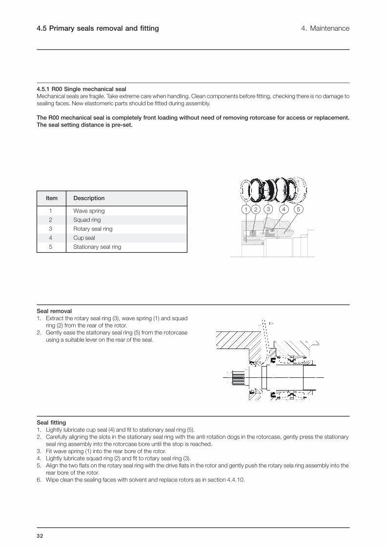
4.5.1 R00 Single mechanical seal
Mechanical seals are fragile. Take extreme care when handling. Clean components before fitting, checking there is no damage to
sealing faces. New elastomeric parts should be fitted during assembly.
The R00 mechanical seal is completely front loading without need of removing rotorcase for access or replacement.
The seal setting distance is pre-set.
Item Description
1 Wave spring
2 Squad ring
3 Rotary seal ring
4 Cup seal
5 Stationary seal ring
Seal removal
1. Extract the rotary seal ring (3), wave spring (1) and squad
ring (2) from the rear of the rotor.
2. Gently ease the staitonary seal ring (5) from the rotorcase
using a suitable lever on the rear of the seal.
Seal fitting
1. Lightly lubricate cup seal (4) and fit to stationary seal ring (5).
2. Carefully aligning the slots in the stationary seal ring with the anti rotation dogs in the rotorcase, gently press the stationary
seal ring assembly into the rotorcase bore until the stop is reached.
3. Fit wave spring (1) into the rear bore of the rotor.
4. Lightly lubricate squad ring (2) and fit to rotary seal ring (3).
5. Align the two flats on the rotary seal ring with the drive flats in the rotor and gently push the rotary sela ring assembly into the
rear bore of the rotor.
6. Wipe clean the sealing faces with solvent and replace rotors as in section 4.4.10.
531 2 4

33
4. Maintenance 4.5 Primary seals removal and fitting
4.5.2 R00 Single flushed/quench mechanical seal
The R00 mechanical seal is completely front loading without need of removing rotorcase for access or replacement.
The seal setting distance is pre-set.
Seal removal
1. Isolate the flush.
2. Extract the rotary seal ring (3), wave spring (1) and squad
ring (2) from the rear of the rotor.
3. Gently ease the stationary seal ring (5) from the rotorcase
using a suitable lever on the rear of the seal.
Seal fitting
1. Lightly lubricate cup seal (4) and stationary seal ring o-ring (6).
2. Fit cup seal and o-ring to stationary seal rings (5).
3. Fit lip seal (7) into stationary seal assembly.
4. Carefully aligning the slots of the stationary seal ring with the anti rotation dogs in the rotorcase, gently press the stationary
seal ring assembly into the rotorcase bore until the stop is reached.
5. Fit wave spring (1) into the rear bore of the rotor.
6. Lightly lubricate squad ring (2) and fit to rotary seal ring (3).
7. Replace the spline sealing o-ring (8).
8. Align the two flats on the rotary seal ring with the drive flts in the rotor and gently push the rotary seal ring assembly into the
rear bore of the rotor.
9. Wipe clean the sealing faces with solvent and replace rotors as 4.4.10.
Item Description
1 Wave spring
2 Squad ring
3 Rotary seal ring
4 Cup seal
5 Stationary seal ring
6 Stationary seal ring o-ring
7 Lip seal
8 Spline sealing o-ring
1 2 3 54
8
76

34
4.5 Primary seal removal and fitting 4. Maintenance
4.5.3 R00 Double flushed mechanical seal
The R00 mechanical seal is completely front loading without need of removing rotorcase for access or replacement.
The seal setting distance is pre-set.
Seal removal
1. Isolate the flush.
2. Extract the rotary seal ring (3), wave spring (1) and squad
ring (2) from the rear of the rotor.
3. Gently ease the stationary seal ring (5) from the rotorcase
using a suitable lever at the rear of the seal.
8
9
103 4 5 6 71 2
Seal fitting
1. Lightly lubricate cup seal (4) and stationary seal ring o-ring (6).
2. Fit cup seal and o-ring to stationary seal rin g (5) and then lubricate and fit rotary seal ring o-ring (8) into outboard rotary seal
ring (7).
3. Slide wave spring (10) along shaft through the rotorcase bore until located on shaft shoulder. Wipe clean the sealing faces with
solvent.
4. Fit outboard rotary seal assembly, ensuring the drive pins (9) engage with slots in the shaft.
5. Carefully aligning the slots of the stationary seal ring with the anti rotation dogs in the rotorcase, gently press the stationary
seal ring assembly into the rotorcase bore until the stop is reached.
6. Fit wave spring (1) into the rear bore of the rotor and replace the spline sealing o-ring (11).
7. Lightly lubricate squad ring (2) and fit to rotary seal ring (3).
NOTE!
If the flushing pressure is in excess of 5 bar above the discharge pressure an o-ring is specified in place of the squad ring.
8. Align the two flats on the rotary sela ring with the drive flats in the rotor and gently push the rotary seal ring assembly into the
rear bore of the rotor. Wipe clean the sealing faces with solvent and replace rotors as in section 4.4.10.
Item Description
1 Wave spring
2 Squad ring
3 Rotary seal ring (inboard)
4 Cup seal
5 Stationary seal ring
6 Stationary seal ring o-ring
7 Stationary seal ring o-ring (outboard)
8 Rotary seal ring o-ring
9 Drive pin
10 Wave spring
11 Spline sealing o-ring
11

35
No
flo
w
Und
er
cap
acity
Irre
gula
r d
ischarg
e
Low
dis
charg
e p
ressure
Pum
p w
ill n
ot
prim
e
Prim
e lost
after
sta
rtin
g
Pum
p s
talls
when s
tart
ing
Pum
p o
verh
eats
Moto
r ove
rheats
Excessiv
e p
ow
er
ab
sorb
ed
Nois
e a
nd
vib
ration
Pum
p e
lem
ent
wear
Syp
ho
nin
g
Seiz
ure
Mechanic
al
seal
leakag
e
4. Maintenance 4.6 Troubleshooting
Problem
Probable Causes Solutions
!!!!! !!!!! Incorrect direction of rotation. Reverse motor.
!!!!! Pump not primed. Expel gas from suction line and pumping chamber and
introduce fluid.
Increase suction line diameter.
!!!!! !!!!! !!!!! !!!!! !!!!! !!!!! Insufficient NPSH available. Increase suction head.
Simplify suction line configuration and reduce length.
Reduce pump speed.
Increase suction line diameter.
!!!!! !!!!! !!!!! !!!!! !!!!! Fluid vaporising in suction line. Increase suction head.
Simplify suction line configuration and reduce length.
Reduce pump speed.
!!!!! !!!!! !!!!! !!!!! !!!!! !!!!! Air entering suction line. Remake pipework joints.
!!!!! !!!!! !!!!! !!!!! !!!!! Strainer or filter blocked. Service fittings.
Increase fluid temperature.
!!!!! !!!!! !!!!! !!!!! !!!!! !!!!! !!!!! Fluid viscosity above rated figure. Decrease pump speed.
Check seal face viscosity limitations.
!!!!! !!!!! !!!!! Fluid viscosity below rated figure. Decrease fluid temperature.
Increase pump speed.
Cool the pump casing.
!!!!! !!!!! !!!!! !!!!! !!!!! Fluid temp. above rated figure. Reduce fluid temperature.
Check seal face and elastomer temp. limitations.
!!!!! !!!!! !!!!! Fluid temp. below rated figure. Heat the pump casing.
Increase fluid temperature.
Clean the system.
!!!!! !!!!! !!!!! !!!!! Unexpected solids in fluid. Fit strainer to suction line.
If solids cannot be eliminated, consider fitting double
mechanical seals.
Discharge pressure above rated Check for obstructions i.e. closed valve.
!!!!! !!!!! !!!!! !!!!! !!!!! !!!!! !!!!! !!!!! !!!!! !!!!! !!!!! !!!!! figure Service system and change to prevent problem recurring.
Simplify discharge line to decrease pressure.
!!!!! Seal flushing inadequate. Increase flush flow rate.
Check that flush fluid flows freely into seal area.
!!!!! !!!!! !!!!! !!!!! Pump speed above rated figure. Decrease pump speed.
!!!!! !!!!! Pump speed below rated figure. Increase pump speed.
Check alignment of pipes.
!!!!! !!!!! !!!!! !!!!! !!!!! !!!!! !!!!! Pump casing strained by pipework. Fit flexible pipes or expansion fittings.
Support pipework.
!!!!! !!!!! !!!!! !!!!! Flexible coupling misaligned. Check alignment and adjust mountings accordingly.
!!!!! !!!!! !!!!! !!!!! !!!!! !!!!! Insecure pump driver mountings. Fit lock washers to slack fasteners and re-tighten.
!!!!! !!!!! !!!!! !!!!! !!!!! !!!!! !!!!! Shaft bearing wear or failure. Refer to pump maker for advice and replacement parts.
!!!!! !!!!! !!!!! !!!!! !!!!! !!!!! Insufficient gearcase lubrication. Refer to pump maker’s instructions.
!!!!! !!!!! !!!!! !!!!! !!!!! !!!!! !!!!! !!!!! Metal to metal contact of pumping Check rated and duty pressures.
element. Refer to pump maker.
!!!!! !!!!! !!!!! Worn pumping element. Fit new components.
!!!!! !!!!! Suction lift too high. Lower pump or raise liquid level.
!!!!! Fluid pumped not compatible Use optional materials.
with materials used
!!!!! No barrier in system to prevent flow Ensure discharge pipework higher than suction tank.
passing.
!!!!! Pump allowed to run dry. Ensure system operation prevents this.
Fit single or double flushed mechanical seals.
!!!!! !!!!! Faulty motor. Check and replace motor bearings.
!!!!! Pumping element missing Fit pumping element.
36
5.1 Technical data 5. Technical data
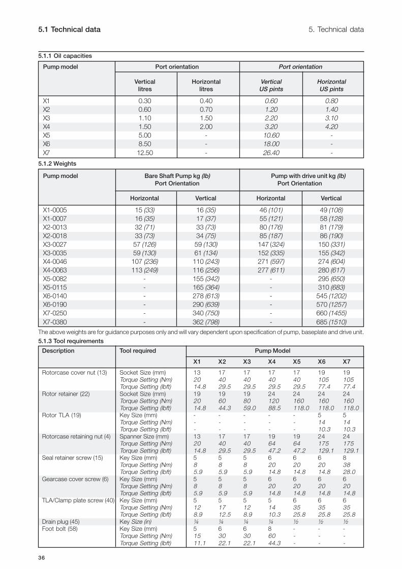
5.1.1 Oil capacities
5.1.2 Weights
The above weights are for guidance purposes only and will vary dependent upon specification of pump, baseplate and drive unit.
5.1.3 Tool requirements
Pump model Port orientation Port orientation
Vertical Horizontal Vertical Horizontal
litres litres US pints US pints
X1 0.30 0.40 0.60 0.80
X2 0.60 0.70 1.20 1.40
X3 1.10 1.50 2.20 3.10
X4 1.50 2.00 3.20 4.20
X5 5.00 - 10.60 -
X6 8.50 - 18.00 -
X7 12.50 - 26.40 -
Pump model Bare Shaft Pump kg (lb) Pump with drive unit kg (lb)
Port Orientation Port Orientation
Horizontal Vertical Horizontal Vertical
X1-0005 15 (33) 16 (35) 46 (101) 49 (108)
X1-0007 16 (35) 17 (37) 55 (121) 58 (128)
X2-0013 32 (71) 33 (73) 80 (176) 81 (179)
X2-0018 33 (73) 34 (75) 85 (187) 86 (190)
X3-0027 57 (126) 59 (130) 147 (324) 150 (331)
X3-0035 59 (130) 61 (134) 152 (335) 155 (342)
X4-0046 107 (236) 110 (243) 271 (597) 274 (604)
X4-0063 113 (249) 116 (256) 277 (611) 280 (617)
X5-0082 - 155 (342) - 295 (650)
X5-0115 - 165 (364) - 310 (683)
X6-0140 - 278 (613) - 545 (1202)
X6-0190 - 290 (639) - 570 (1257)
X7-0250 - 340 (750) - 660 (1455)
X7-0380 - 362 (798) - 685 (1510)
Description Tool required Pump Model
X1 X2 X3 X4 X5 X6 X7
Rotorcase cover nut (13) Socket Size (mm) 13 17 17 17 17 19 19
Torque Setting (Nm) 20 40 40 40 40 105 105Torque Setting (lbft) 14.8 29.5 29.5 29.5 29.5 77.4 77.4
Rotor retainer (22) Socket Size (mm) 19 19 19 24 24 24 24Torque Setting (Nm) 20 60 80 120 160 160 160Torque Setting (lbft) 14.8 44.3 59.0 88.5 118.0 118.0 118.0
Rotor TLA (19) Key Size (mm) - - - - - 5 5
Torque Setting (Nm) - - - - - 14 14Torque Setting (lbft) - - - - - 10.3 10.3
Rotorcase retaining nut (4) Spanner Size (mm) 13 17 17 19 19 24 24Torque Setting (Nm) 20 40 40 64 64 175 175Torque Setting (lbft) 14.8 29.5 29.5 47.2 47.2 129.1 129.1
Seal retainer screw (15) Key Size (mm) 5 5 5 6 6 6 8
Torque Setting (Nm) 8 8 8 20 20 20 38Torque Setting (lbft) 5.9 5.9 5.9 14.8 14.8 14.8 28.0
Gearcase cover screw (6) Key Size (mm) 5 5 5 6 6 6 6Torque Setting (Nm) 8 8 8 20 20 20 20Torque Setting (lbft) 5.9 5.9 5.9 14.8 14.8 14.8 14.8
TLA/Clamp plate screw (40) Key Size (mm) 5 5 5 5 6 6 6
Torque Setting (Nm) 12 17 12 14 35 35 35Torque Setting (lbft) 8.9 12.5 8.9 10.3 25.8 25.8 25.8
Drain plug (45) Key Size (in) ¼ ¼ ¼ ¼ ½ ½ ½Foot bolt (58) Key Size (mm) 5 6 6 8 - - -
Torque Setting (Nm) 15 30 30 60 - - -
Torque Setting (lbft) 11.1 22.1 22.1 44.3 - - -

37
5.1 Technical data 5. Technical data
5.1.4 Technical specifications
Model Displacement Suction & Discharge Differential Maximum Maximum
Connection Size Pressure Speed Capacity at
Max Speed
litres/rev Imp gal/ US gal/ Nominal Bore Connection Size
100 rev 100 rev Diameter (International Std)
(Standard)
mm inches mm inches bar psi rev/min m3/hr
X1/0005 0,050 1,1 1,3 22 0,87 25 1,0 12 174 1400 4
X1/0007 0,070 1,5 1,8 35 1,38 40 1,5 7 101 1400 6
X2/0013 0,128 2,8 3,4 35 1,38 40 1,5 15 217 1000 8
X2/0018 0,181 4,0 4,8 47 1,85 50 2,0 7 101 1000 11
X3/0027 0,266 5,9 7,0 47 1,85 50 2,0 15 217 1000 16
X3/0035 0,350 7,7 9,2 62 2,44 65 2,5 7 101 1000 21
X4/0046 0,460 10,1 12,2 47 1,85 50 2,0 15 217 1000 28
X4/0063 0,630 13,9 16,6 62 2,44 65 2,5 10 145 1000 38
X5/0082 0,820 18,0 21,7 62 2,44 65 2,5 15 217 600 30
X5/0115 1,150 25,3 30,4 73 2,87 80 3,0 10 145 600 41
X6/0140 1,400 30,8 37,0 73 2,87 80 3,0 15 217 500 42
X6/0190 1,900 41,8 50,2 96 3,78 100 4,0 10 145 500 57
X7/0250 2,500 55,0 66,0 96 3,78 100 4,0 15 217 500 75
X7/0380 3,800 83,6 100,4 140 5,51 150 6,0 10 145 500 114
38
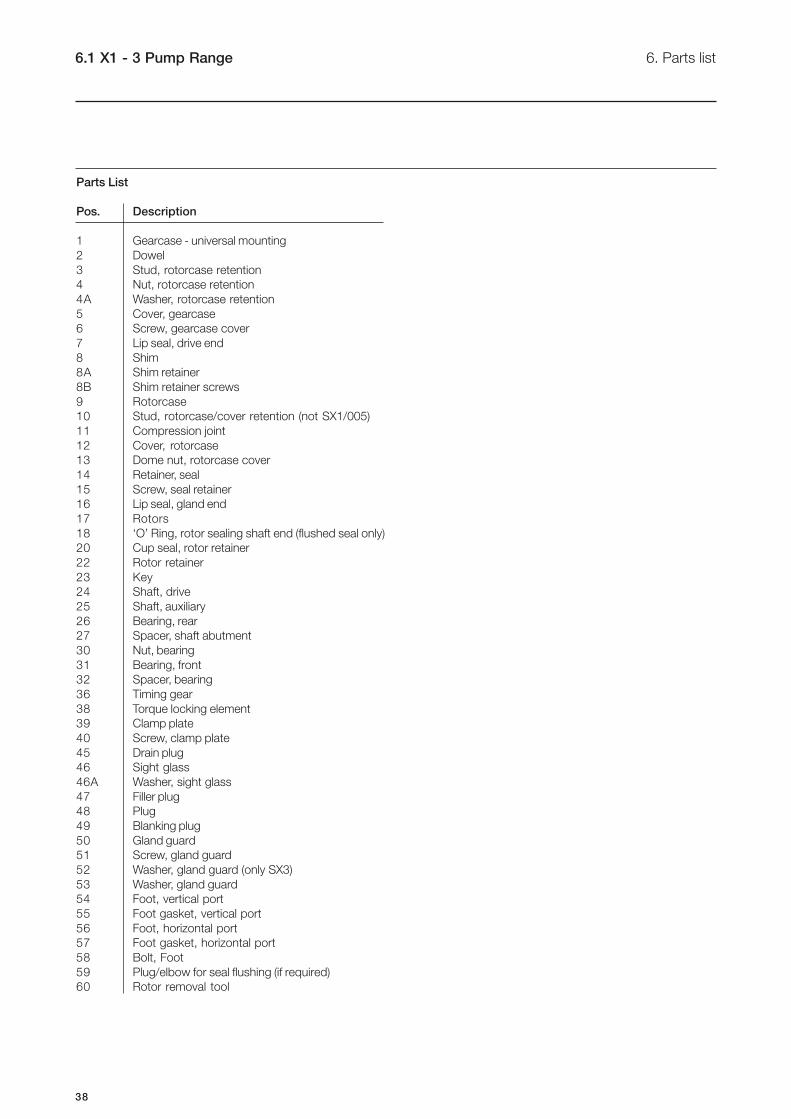
6.1 X1 - 3 Pump Range 6. Parts list
Parts List
Pos. Description
1 Gearcase - universal mounting
2 Dowel
3 Stud, rotorcase retention
4 Nut, rotorcase retention
4A Washer, rotorcase retention
5 Cover, gearcase
6 Screw, gearcase cover
7 Lip seal, drive end
8 Shim
8A Shim retainer
8B Shim retainer screws
9 Rotorcase
10 Stud, rotorcase/cover retention (not SX1/005)
11 Compression joint
12 Cover, rotorcase
13 Dome nut, rotorcase cover
14 Retainer, seal
15 Screw, seal retainer
16 Lip seal, gland end
17 Rotors
18 ‘O’ Ring, rotor sealing shaft end (flushed seal only)
20 Cup seal, rotor retainer
22 Rotor retainer
23 Key
24 Shaft, drive
25 Shaft, auxiliary
26 Bearing, rear
27 Spacer, shaft abutment
30 Nut, bearing
31 Bearing, front
32 Spacer, bearing
36 Timing gear
38 Torque locking element
39 Clamp plate
40 Screw, clamp plate
45 Drain plug
46 Sight glass
46A Washer, sight glass
47 Filler plug
48 Plug
49 Blanking plug
50 Gland guard
51 Screw, gland guard
52 Washer, gland guard (only SX3)
53 Washer, gland guard
54 Foot, vertical port
55 Foot gasket, vertical port
56 Foot, horizontal port
57 Foot gasket, horizontal port
58 Bolt, Foot
59 Plug/elbow for seal flushing (if required)
60 Rotor removal tool
39
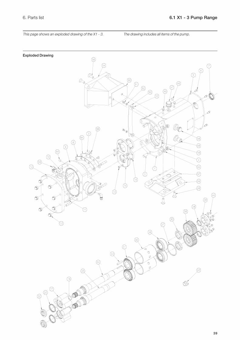
6. Parts list 6.1 X1 - 3 Pump Range
This page shows an exploded drawing of the X1 - 3. The drawing includes all items of the pump.
Exploded Drawing
40
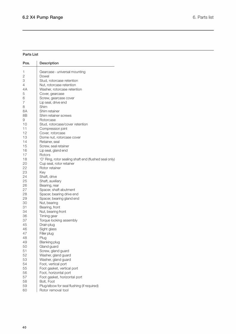
6.2 X4 Pump Range 6. Parts list
Parts List
Pos. Description
1 Gearcase - universal mounting
2 Dowel
3 Stud, rotorcase retention
4 Nut, rotorcase retention
4A Washer, rotorcase retention
5 Cover, gearcase
6 Screw, gearcase cover
7 Lip seal, drive end
8 Shim
8A Shim retainer
8B Shim retainer screws
9 Rotorcase
10 Stud, rotorcase/cover retention
11 Compression joint
12 Cover, rotorcase
13 Dome nut, rotorcase cover
14 Retainer, seal
15 Screw, seal retainer
16 Lip seal, gland end
17 Rotors
18 ‘O’ Ring, rotor sealing shaft end (flushed seal only)
20 Cup seal, rotor retainer
22 Rotor retainer
23 Key
24 Shaft, drive
25 Shaft, auxiliary
26 Bearing, rear
27 Spacer, shaft abutment
28 Spacer, bearing drive end
29 Spacer, bearing gland end
30 Nut, bearing
31 Bearing, front
34 Nut, bearing front
36 Timing gear
37 Torque locking assembly
45 Drain plug
46 Sight glass
47 Filler plug
48 Plug
49 Blanking plug
50 Gland guard
51 Screw, gland guard
52 Washer, gland guard
53 Washer, gland guard
54 Foot, vertical port
55 Foot gasket, vertical port
56 Foot, horizontal port
57 Foot gasket, horizontal port
58 Bolt, Foot
59 Plug/elbow for seal flushing (if required)
60 Rotor removal tool

41
6. Parts list 6.2 X4 Pump Range
This page shows an exploded drawing of the X4. The drawing includes all items of the pump.
Exploded Drawing
42
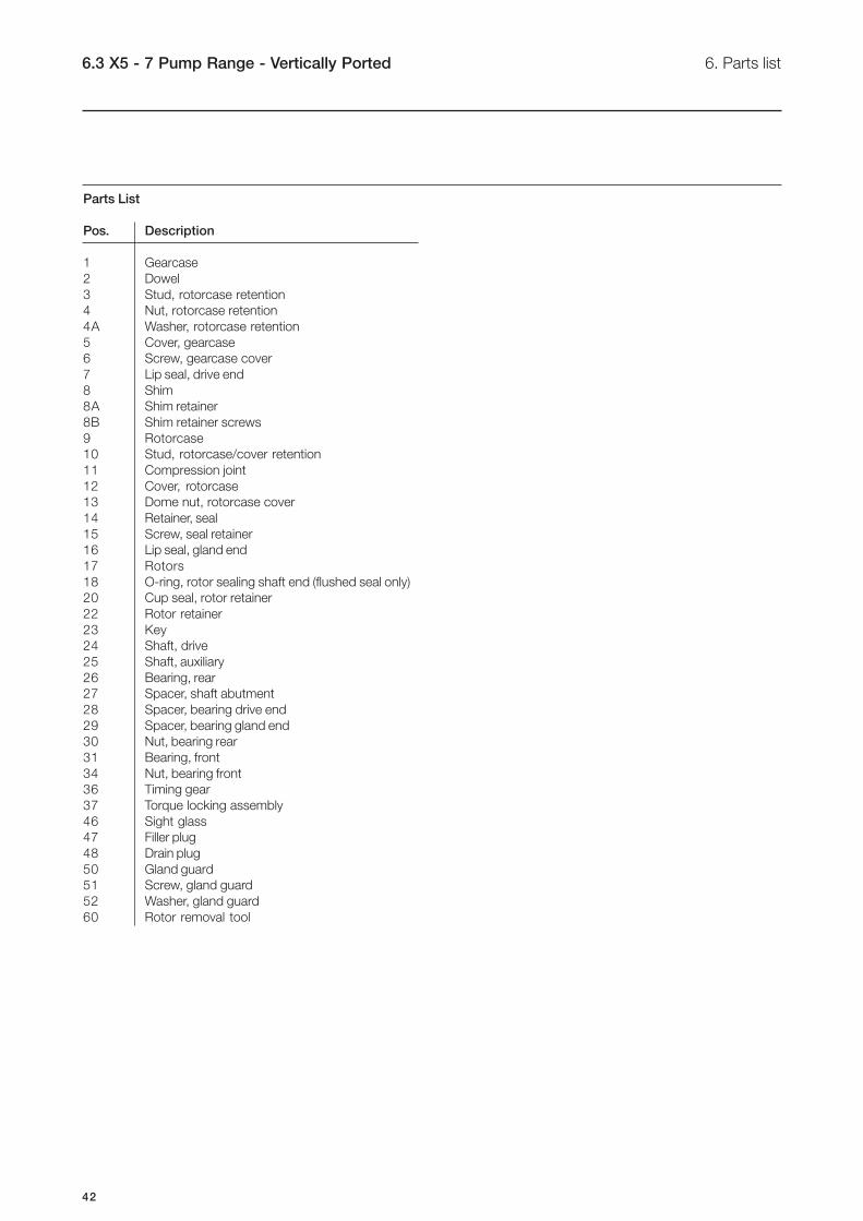
6.3 X5 - 7 Pump Range - Vertically Ported 6. Parts list
Parts List
Pos. Description
1 Gearcase
2 Dowel
3 Stud, rotorcase retention
4 Nut, rotorcase retention
4A Washer, rotorcase retention
5 Cover, gearcase
6 Screw, gearcase cover
7 Lip seal, drive end
8 Shim
8A Shim retainer
8B Shim retainer screws
9 Rotorcase
10 Stud, rotorcase/cover retention
11 Compression joint
12 Cover, rotorcase
13 Dome nut, rotorcase cover
14 Retainer, seal
15 Screw, seal retainer
16 Lip seal, gland end
17 Rotors
18 O-ring, rotor sealing shaft end (flushed seal only)
20 Cup seal, rotor retainer
22 Rotor retainer
23 Key
24 Shaft, drive
25 Shaft, auxiliary
26 Bearing, rear
27 Spacer, shaft abutment
28 Spacer, bearing drive end
29 Spacer, bearing gland end
30 Nut, bearing rear
31 Bearing, front
34 Nut, bearing front
36 Timing gear
37 Torque locking assembly
46 Sight glass
47 Filler plug
48 Drain plug
50 Gland guard
51 Screw, gland guard
52 Washer, gland guard
60 Rotor removal tool

43
6. Parts list 6.3 X5 - 7 Pump Range - Vertically ported
This page shows an exploded drawing of the X5 - 7
- vertically ported.
The drawing includes all items of the pump.
44
7.1 Appendix A 7. Appendix
ATEX Directive 94/9/EC
The ATEX Directive 94/9/EC covers equipment and protective systems that will be used in areas endangered by potentially
explosive atmospheres created by the presence of flammable gases, vapours and dusts. Rotary Lobe Pumps supplied with
an ATEX symbol are classified for use in potentially explosive atmospheres under ATEX Directive 94/9/EC Group II,
Categories 2 and 3.
Technical File Ref: SXex – 1/7 Document reference no. 9612-9602-01
Type of Equipment: Rotary Lobe Positive Displacement Pumps
Equipment Group: Group II category 2 G (zone 1) and D (zone 21)
and Category Group II category 3 G (zone 2) and D (zone 22)
For Temperature class see table below
Ignition Protection used: EN13463-1: 2001 c k
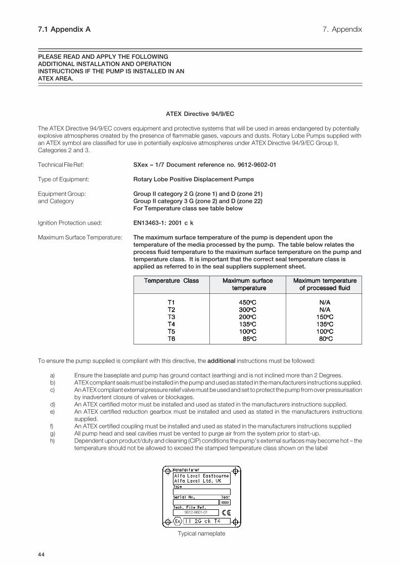
Maximum Surface Temperature: The maximum surface temperature of the pump is dependent upon the
temperature of the media processed by the pump. The table below relates the
process fluid temperature to the maximum surface temperature on the pump and
temperature class. It is important that the correct seal temperature class is
applied as referred to in the seal suppliers supplement sheet.
To ensure the pump supplied is compliant with this directive, the additional instructions must be followed:
a) Ensure the baseplate and pump has ground contact (earthing) and is not inclined more than 2 Degrees.
b) ATEX compliant seals must be installed in the pump and used as stated in the manufacturers instructions supplied.
c) An ATEX compliant external pressure relief valve must be used and set to protect the pump from over pressurisation
by inadvertent closure of valves or blockages.
d) An ATEX certified motor must be installed and used as stated in the manufacturers instructions supplied.
e) An ATEX certified reduction gearbox must be installed and used as stated in the manufacturers instructions
supplied.
f) An ATEX certified coupling must be installed and used as stated in the manufacturers instructions supplied
g) All pump head and seal cavities must be vented to purge air from the system prior to start-up.
h) Dependent upon product/duty and cleaning (CIP) conditions the pump’s external surfaces may become hot – the
temperature should not be allowed to exceed the stamped temperature class shown on the label
PLEASE READ AND APPLY THE FOLLOWING
ADDITIONAL INSTALLATION AND OPERATION
INSTRUCTIONS IF THE PUMP IS INSTALLED IN AN
ATEX AREA.
Temperature ClassTemperature ClassTemperature ClassTemperature ClassTemperature Class Maximum surfaceMaximum surfaceMaximum surfaceMaximum surfaceMaximum surface Maximum temperature Maximum temperature Maximum temperature Maximum temperature Maximum temperature
temperature temperature temperature temperature temperature of processed fluid of processed fluid of processed fluid of processed fluid of processed fluid
T1T1T1T1T1 450450450450450oooooCCCCC N/A N/A N/A N/A N/A
T2T2T2T2T2 300300300300300oooooCCCCC N/A N/A N/A N/A N/A
T3T3T3T3T3 200200200200200oooooCCCCC 150 150 150 150 150oooooCCCCC
T4T4T4T4T4 135135135135135oooooCCCCC 135 135 135 135 135oooooCCCCC
T5T5T5T5T5 100100100100100oooooCCCCC 100 100 100 100 100oooooCCCCC
T6T6T6T6T6 85 85 85 85 85oooooCCCCC 80 80 80 80 80oooooCCCCC
9612-9601-01
Typical nameplate

45
7. Appendix 7.2 Appendix B
ATEX Directive 94/9/EC
The ATEX Directive 94/9/EC covers equipment and protective systems that will be used in areas endangered by potentially
explosive atmospheres created by the presence of flammable gases, vapours and dusts. Rotary Lobe Pumps supplied with an
ATEX symbol are classified for use in potentially explosive atmospheres under ATEX Directive 94/9/EC Group II, Categories 2.
Technical File Ref: SXex – 1/7 Document reference no. 9612-9602-01
Type of Equipment: Rotary Lobe Positive Displacement Pumps
Equipment Group: Group II category 2 G (zone 1) and D (zone 21)
and Category For Temperature class see table below
Ignition Protection used: EN13463-1: 2001 c k
Maximum Surface Temperature The maximum surface temperature of the pump is dependent upon the temperature
of the media processed by the pump. The table below relates the process fluid
temperature to the maximum surface temperature on the pump and temperature
class. It is important that the correct seal temperature class is applied as referred
to in the seal suppliers supplement sheet.
To ensure the pump supplied is compliant with this directive, the additional instructions must be followed:
a) Apply all additional instructions listed in Appendix A.
b) Dependent upon product/duty and cleaning (CIP) conditions the pump’s external surfaces may become hot – the
temperature should not be allowed to exceed the stamped temperature class shown on the machines label. Daily
checks must be made for any signs of overheating and/or paint discolouration.
c) The weekly maintenance checks listed in the Maintenance Schedule should be made on a daily basis, and a daily
check on the lubrication for signs of contamination must be added.
d) Pump gearbox bearings must be renewed every 2 years or 9000 hours whichever is first.
e) Replace gearbox lip seals if disturbed i.e. cover removed.
f) A pressure gauge and control valve should be fitted to the seal flush outlet pipe work, and a minimum back pressure
of 0.3 bar applied during operation.
PLEASE READ AND APPLY THE FOLLOWING
ADDITIONAL INSTALLATION AND OPERATION
INSTRUCTIONS IF THE PUMP IS INSTALLED IN AN
ATEX ZONE 1 OR ZONE 21 AREAS
Temperature ClassTemperature ClassTemperature ClassTemperature ClassTemperature Class Maximum surfaceMaximum surfaceMaximum surfaceMaximum surfaceMaximum surface Maximum temperature Maximum temperature Maximum temperature Maximum temperature Maximum temperature
temperature temperature temperature temperature temperature of processed fluid of processed fluid of processed fluid of processed fluid of processed fluid
T1T1T1T1T1 450450450450450oooooCCCCC N/A N/A N/A N/A N/A
T2T2T2T2T2 300300300300300oooooCCCCC N/A N/A N/A N/A N/A
T3T3T3T3T3 200200200200200oooooCCCCC 150 150 150 150 150oooooCCCCC
T4T4T4T4T4 135135135135135oooooCCCCC 135 135 135 135 135oooooCCCCC
T5T5T5T5T5 100100100100100oooooCCCCC 100 100 100 100 100oooooCCCCC
T6T6T6T6T6 85 85 85 85 85oooooCCCCC 80 80 80 80 80oooooCCCCC