
Operating Manual PrimaX - Keison Products · Safety Regulations MSA 6 PrimaX GB 1 Safety...
57
Operating Manual PrimaX Gas Transmitter Order No. 10115083/00
Transcript of Operating Manual PrimaX - Keison Products · Safety Regulations MSA 6 PrimaX GB 1 Safety...

Operating Manual
PrimaXGas Transmitter
Order No. 10115083/00

Declaration of ConformityMSA
PrimaXGB 3
Declaration of Conformity
The manufacturer or his in the community established authorized representative
MSA AUER GmbHThiemannstraße 1D-12059 Berlin
declares that the product
PrimaX I, PrimaX P
based on the EC-Type Examination Certificate: BVS 10 ATEX E009 Xcomplies with the ATEX directive 94/9/EC, Annex III. Quality Assurance Notification complying with Annex IV of the ATEX Directive 94/9/EC has been issued by DEKRA EXAM in Bochum, Notified Body number: 0158.
The product is in conformance with the directive 2004/108/EC,[EMC]:EN 50270:2007 Typ 2, EN 61000-6-3:2007
MSA AUER GmbHDr. Axel SchubertR&D Instruments
Berlin, June 2010

MSAContents
PrimaX4 GB
Contents
1 Declaration of Conformity ..................................................................................... 3
2 Safety Regulations ................................................................................................. 6
2.1 Correct Use .................................................................................................. 6
2.2 Liability Information ....................................................................................... 6
2.3 Safety and Precautionary Measures to be Adopted ..................................... 7
2.4 MSA Permanent Instrument Warranty .......................................................... 8
3 Description ............................................................................................................. 9
3.1 Identifying the Unit ........................................................................................ 9
3.2 Overview ....................................................................................................... 9
4 Installation ............................................................................................................ 11
4.1 Mechanical Installation ............................................................................... 12
4.2 Electrical Installation ................................................................................... 14
5 Operation .............................................................................................................. 17
5.1 Startup ........................................................................................................ 18
5.2 Menu Sequence ......................................................................................... 19
5.3 Calibrations ................................................................................................. 20
5.4 Maintenance and Info ................................................................................. 22
5.5 Password .................................................................................................... 26
5.6 Changeable Parameters ............................................................................. 26
5.7 Optional HART Module and Relay ............................................................. 27
6 Maintenance ......................................................................................................... 33
6.1 Changing the Sensors ................................................................................ 33

ContentsMSA
PrimaXGB 5
7 Technical Data ...................................................................................................... 35
7.1 Specifications ............................................................................................. 35
7.2 Cable Lengths and Cross-sections ............................................................. 36
7.3 Performance Specifications ........................................................................ 37
7.4 List of Detectable Gases ............................................................................ 37
7.5 Sensor Response to Interferants ................................................................ 39
8 Approvals ............................................................................................................. 42
8.1 Marking, Certificates and Approvals According to the Directive 94/9/EC [ATEX] ................................................ 42
8.2 Marking and Certificates according to IECEx ............................................. 44
9 Accessories .......................................................................................................... 46
9.1 Sensor Gard ............................................................................................... 46
9.2 Flow Through Adapter ................................................................................ 46
9.3 Duct Mounting Kit ....................................................................................... 46
9.4 Pipe Mounting Kit ....................................................................................... 47
9.5 Sensor Tag ................................................................................................. 47
9.6 Sunshield .................................................................................................... 47
9.7 Universal HART Cable ............................................................................... 47
10 Spare Parts ........................................................................................................... 47
11 Appendix ............................................................................................................... 50
11.1 Output States .............................................................................................. 50
11.2 Calibration Faults ........................................................................................ 51
11.3 Error Codes ................................................................................................ 51
11.4 Timeout ....................................................................................................... 52
11.5 Mechanical Installation ............................................................................... 52
11.6 Wiring Diagrams ......................................................................................... 53

MSASafety Regulations
PrimaX6 GB
1 Safety Regulations1.1 Correct Use
The PrimaX Gas Transmitters are fixed gas transmitters for measuring toxic or combustible gases or oxygen. They are suitable for outdoor and indoor applications without limitations, e.g. offshore industry, chemical and petrochemical industry, wa-ter and sewage industry. The signal of the transmitter can be used in combination with MSA control units for further actions in safety or non safety applications, e. g. MSA SUPREMA, Gasgard XL, 9010/9020.The two versions of the gas transmitter are delivered either in a flameproof or in a intrinsically safe enclosure. The electrical parts and interfaces have the same basic functionality.It is imperative that this operating manual be read and observed when using the product. In particular, the safety instructions, as well as the information for the use and operation of the product, must be carefully read and observed. Furthermore, the national regulations applicable in the user's country must be taken into account for a safe use.
Alternative use, or use outside this specification will be considered as non-compli-ance. This also applies especially to unauthorised alterations to the product and to commissioning work that has not been carried out by MSA or authorised persons.
1.2 Liability InformationMSA accepts no liability in cases where the product has been used inappropriately or not as intended. The selection and use of the product are the exclusive respon-sibility of the individual operator.Product liability claims, warranties also as guarantees made by MSA with respect to the product are voided, if it is not used, serviced or maintained in accordance with the instructions in this manual.
Danger!This product is supporting life and health. Inappropriate use, mainte-nance or servicing may affect the function of the device and thereby se-riously compromise the user's life.Before use the product operability must be verified. The product must not be used if the function test is unsuccessful, it is damaged, a compe-tent servicing/maintenance has not been made, genuine MSA spare parts have not been used.

Safety RegulationsMSA
PrimaXGB 7
1.3 Safety and Precautionary Measures to be Adopted
- The device described in this manual must be installed, operated and maintained in strict accordance with their labels, cautions, instructions, and within the limi-tations stated.
- The device is designed to detect gases or vapours in air.
- Protect the device from extreme vibration. Do not mount the sensing head in di-rect sunlight as this may cause overheating of the sensor.
- The device must be installed with the sensor inlet pointing downwards to avoid clogging of the gas inlet by particles or liquids.
- Electrochemical sensors are sealed units which contain a corrosive electrolyte. Should a sensor develop leakage, it must be immediately removed from service and disposed of properly. Caution must be exercised so that the electrolyte does not contact skin, clothing or circuitry otherwise personal injury [burns] and/or equipment damage may result.
- The only absolute method to ensure proper overall operation of the device is to check it with a known concentration of the gas for which it has been calibrated. Consequently, calibration checks must be included as part of the routine inspec-tion of the system.
- As with all devices of these types, high levels of, or long exposure to, certain compounds in the tested atmosphere could contaminate the sensor. In atmos-pheres where the device may be exposed to such materials, calibration must be performed frequently to ensure that the operation is dependable and display in-dications are accurate.
- The device must not be painted. If painting is done in an area where a device is located, care must be exercised to ensure that paint is not deposited on the sin-tered metal flashback arrestor in the gas sensor inlet, if so equipped. Such paint deposits would interfere with the gas diffusion process.
- Use only genuine MSA replacement parts when performing any maintenance procedures provided in this manual. Failure to do so may seriously impair instru-ment performance. Repair or alteration of the device, beyond the scope of these
Attention!The following safety instructions must be observed implicitly. Only in this way can the safety and health of the individual operators, and the correct functioning of the instrument, be guaranteed.

MSASafety Regulations
PrimaX8 GB
maintenance instructions or by anyone other than an authorised MSA service personnel, could cause the product to fail to perform as designed.
- The device is designed for applications in hazardous areas under atmospheric conditions.
- For correct measurements, the combustible gas sensors require an oxygen concentration greater than 10 Vol%. Oxygen enriched atmospheres, greater then 21 Vol%, can affect the measurement and the electrical safety of the de-vice.
- The response time of the device will be increased by significant dust deposits on the Sensor. Checks for dust deposits must be done at regular intervals.
- Catalytic combustible gas sensors may produce low or zero response to com-bustible gas after exposure to substances as Silicon, Silane, Silicate, Halide and compounds containing Fluorine, Chlorine, Iodine or Bromine.
1.4 MSA Permanent Instrument Warranty
WarrantySeller warrants that this product will be free from mechanical defect or faulty work-manship for
- Gas Transmitter: eighteen [18] months from date of shipment or one [1] year from installation, whichever occurs first;
- Oxygen, Toxic or Catalytic Combustible Sensor: eighteen [18] months from date of shipping or one [1] year from installation, whichever occurs first.
This warranty is applicable provided the product is maintained and used in accord-ance with Seller's instructions and/or recommendations. This warranty does not ap-ply to expendable or consumable parts, whose normal life expectancy is less than one [1] year.The Seller shall be released from all obligations under this warranty in the event re-pairs or modifications are made by persons other than its own or authorized service personnel or if the warranty claim results from physical abuse or misuse of the prod-uct. No agent, employee or representative of the Seller has any authority to bind the Seller to any affirmation, representation or warranty concerning the goods sold un-der this contract. Seller makes no warranty concerning components or accessories not manufactured by the Seller, but will pass onto the Purchaser all warranties of manufacturers of such components.

DescriptionMSA
PrimaXGB 9
2 Description2.1 Identifying the Unit
Fig. 1 PrimaX Gas Transmitter
PrimaX PThe PrimaX P is a gas transmitter with an aluminium enclosure. This is a flameproof version for the detection of combustible or toxic gases or oxygen.
PrimaX IThe PrimaX I is a gas transmitter with a plastic enclosure. It is available as a general purpose version [not intended for hazardous area] or intrinsically safe version. Both versions are designed for a detection of toxic gases or oxygen.
2.2 OverviewThe device is factory-calibrated and delivered ready for installation. Each device is configured and calibrated for only one specific gas or vapour.
PrimaX P PrimaX I
flameproof versiongeneral purpose version, or
intrinsically safe version

MSADescription
PrimaX10 GB
The enclosures vary depending on the particular version. The electrical parts and interfaces have the same basic functionality. The device has:
- a quick and easy pluggable sensor,
- a four digit liquid crystal display [LCD],
- a key pad with a cover
- a detachable backplate for installation on a wall or on a pipe
The device operate with a 4 – 20 mA output signal and an IP 66 ingress protection.
Fig. 2 Exploded View [PrimaX P]
1 Terminal for power connection 6 Sensor
2 Keypad with cover 7 red LED [PrimaX P only]
3 Connector for factory use 8 yellow LED [PrimaX P only]
4 Display 9 green LED [PrimaX P only]
5 bayonet joint with interlock 10 Identification plate
1
2
3
789
4
6
5
10

InstallationMSA
PrimaXGB 11
Sensors
The device operates with a 4 – 20 mA output signal and an IP 66 ingress protection.As an optional feature additional modules are available for these configurations of PrimaX transmitter:
For more information on the HART module → chapter 4.7.
3 InstallationThe device should be installed where gas leaks are expected. The installation po-sition depends on the gas density, either in the upper area of the room under the ceiling for gases lighter than air or close to the ground for gases heavier than air. Also consider how air movement may affect the abilty of the device to detect gas. The display on the front of the instrument must always be clearly visible, the view must not be obstructed.
Description PrimaX P PrimaX IDetection of toxic gases X XDetection of oxygen X XDetection of combustible gases X
Modules PrimaX P PrimaX IHART module X XHART + Relays module X -HART+ Relays module with galvanically isolated analogue output X -
Before beginning the installation, check that the delivered components are complete and correct, referring to the shipping documents and the sticker on the shipment carton.
When preparing the assembly, make sure that the mounting arrange-ment is correct for the particular device.

MSAInstallation
PrimaX12 GB
3.1 Mechanical Installation
PreparationTo install the device, first remove the backplate.
Undo Screws(1) Unscrew the device.
Remove Device(2) Remove the device from the backplate
by lifting up the lower edge as shown.

InstallationMSA
PrimaXGB 13
Wall or Pipe MountingFor pipe mounting a pipe mounting kit is necessary [→ chapter 8.4].
Install the Backplate(1) Use the two keyhole slots for attaching
the mounting plate to the wall. Use 6mm diameter srews and suitable plugs.
(2) For a wall installation use the backplate as a template for drilling the holes for the two fixing screws, for a pipe installation use the pipe clip.
(3) Attach the backplate to the wall or the pipe clip with M6 x 20 screws.
The hitch should point away from the wall or pipe.
The straight edge of the backplate should be at the bottom.
Attach the Device to the Backplate(4) Attach the device to the top of the back-
plate.
(5) Fold down the device, till it is closed to the backplate.
Fasten Device(6) Screw the device to the backplate.

MSAInstallation
PrimaX14 GB
3.2 Electrical Installation
Instructions for Electrical Connection
- Shielded cable for measuring devices is recommended.
- Always observe maximum cable lengths and cross-sections [→ chapter 6.2].
- Water or impurities can penetrate the instrument through the cable. In hazar-dous areas, it is recommended to install the cable in a loop just before entry into the instrument or to slightly bend it to prevent water from entering.
Electrical Connection - PrimaX P
Terminal PrimaX P
Attention!The device must be installed only in compliance with the applicable regulations, otherwise the safe operation of the instrument is not guaranteed.
The power supply is defined as 24 VDC. If the input supply voltage at the terminal of the transmitter is less than 10 V, the device will shut down.
Operating the PrimaX I version in hazardous areas requires an intrinsically safe power supply.
Fig. 3 Terminal PrimaX P Fig. 4 Terminal PrimaX P [isolated ground]
1 Power supply [+], 24 V DC 1 Power supply [+], 24 V DC
2 0 V DC 2 0 V DC
3 4 – 20 mA [Signal] 3 4 – 20 mA [Signal]
4 empty 4 Isolated ground
1 2 3 4 1 2 3 4

InstallationMSA
PrimaXGB 15
PrimaX P
(1) Unscrew the interlock between cover and bayonet joint of sensor.
(2) Unscrew the aluminium lid of the enclosure.
(3) Unplug the 4-way terminal block.
It is located behind a plastic cover above the display.
(4) Unscrew clamping nut at the cable gland.
(5) Put clamping nut on the cable
(6) Insert cable for connection into the device.
(7) Connect cable to terminal.
Use a 3-wire shielded cable.
(8) Tighten cable gland clamping nut, check that cable cannot move within the ca-ble gland.
(9) Replace enclosure lid and secure the interlock.
Fig. 5 3-wire connection - PrimaX P
Power supply [+] 24 V DC
4 – 20 mA [Signal]
0 V DC [-]
isolated ground

MSAInstallation
PrimaX16 GB
Electrical Connection - PrimaX I
Terminal PrimaX I
Fig. 6 Terminal PrimaX I
PrimaX I
(1) Remove plastic cover.
It is bolted with 4 screws.
(2) Remove the 2-way terminal block.
It is located behind a plastic cover above the display.
(3) Unscrew clamping nut at the cable gland.
(4) Put clamping nut on the cable
(5) Insert cable for connection into the device.
(6) Connect cable to terminal.
Use a 2-wire shielded cable.
(7) Tighten cable gland clamping nut, check that cable cannot move within the ca-ble gland.
(8) Replace plastic cover and secure the interlock.
1 Power supply [+], 24 V DC
2 4 – 20 mA [Signal]
Fig. 7 2-wire connection - PrimaX I
Power supply [+]
4 – 20 mA [Signal]
1 2

OperationMSA
PrimaXGB 17
4 Operation
Fig. 8 Display overview
The device is factory-calibrated and delivered ready for installation. Each device is configured and calibrated for only one specific gas or va-pour.
1 Measuring value/Menu//Text dimensions 5 Calibration
2 Units 6 Alive signal [flashing]
3 LOC, alarm indication [optional] 7 Maintenance
4 Signal for an active communication
1 2
6 5
37
4

MSAOperation
PrimaX18 GB
4.1 StartupDuring startup a self-test is performed and the output signal is set to the service cur-rent [default 3.0 mA]. The following information is displayed:
Display TestThe display shows all segments.Note: The PrimaX P also shows all LEDs and afterwards the yellow LED is flash-ing during the startup procedure.Software VersionThe display shows the firmware version.SensorThe display shows the configured type of sensor operating with each individual de-tector, e.g.: COMB [combustible], CO, H2S.RangeThe display shows the measuring range predefined for the gas detector, e.g.: 100% LEL.CountdownThe countdown for sensor stability is displayed.Normal OperationAfter countdown, the gas concentration [ppm, vol%, % LEL, % UEG, mg/m3] is displayed. The heart symbol flashes to indicate alive status.

OperationMSA
PrimaXGB 19
4.2 Menu Sequence
Fig. 9 Keypad - operating buttons
To navigate in the menu sequence, 4 buttons are available.In general:
(1) Press ENTER button to get access to the menu sequence.
(2) Press UP or DOWN button till the desired menu is displayed.
(3) Press ENTER button to get access to the menu,
(4) Press ESC button to cancel the process.The following table lists the menu items. Detailled descriptions can be found in the chapters 4.3, 4.4 and 4.5.
1 ESC button 3 ENTER button
2 UP button 4 DOWN button
1
4
2
3

MSAOperation
PrimaX20 GB
4.3 Calibrations
GeneralThe calibration must be done at regular intervals in accordance with applicable na-tional and regional regulations.The device is calibrated at the factory. Nevertheless, it is recommended to re-calibrate the device after installation. The frequency of calibration depends on the duration of use and the chemical exposure of the sensor. New sensors must be calibrated frequently until it is clear from the calibration data that they have stabi-lised.
Menu item Text Password?M-01 Calibration YesM-02 ZERO Calibration YesM-03 Show Test Gas Concentration NoM-04 Setup Calibration YesM-05 Sensor Exchange YesM-06 LCD and LED Test NoM-07 Loop Test YesM-08 Device Info NoM-09 Sensor Info NoM-10 Changing the Range YesM-00 Reset Alarm Yes
Connect power to the device at least one hour before attempting a cal-ibration.Carry out the calibration during commissioning as well as at regular in-tervals. This ensures optimum operation of the sensor.
It is recommended that all calibration components are connected before starting a calibration as it is necessary to apply test gas to the device during a countdown.
The calibration can be performed as a manual or an automatic calibra-tion [→ M-04].

OperationMSA
PrimaXGB 21
Waiting for calibration gasAfter starting any calibration step, calibration gas [zero or test gas] must be applied until calibration step is finished.Automatic Calibration [automatic]: a countdown is displayed. After the count-down the value is measured and displayed until calibration value is stable.Manual Calibration [manual]: the measuring value is displayed, when value is sta-ble the calibration step ends when ENTER is pressed.
Calibration Steps
[M-01] - ZERO and SPAN Gas Calibration(1) Press ENTER and select menu 1.
(2) Press ENTER button.
(3) Enter password [→ chapter 4.5].
(4) Apply zero gas [synthetic air].
(5) Wait until countdown is finished [automatic] or press ENTER [manual].OK is displayed.
(6) Apply test gas.
(7) Wait until calibration is finished [automatic] or press ENTER [manual].OK is displayed.Idle time countdown starts, during this time the test gas can be removed and the output signal remains on service current level.
(8) Remove test gas during the countdown.
[M-01] - Oxygen Calibration(1) Press ENTER and select menu 1.
(2) Press ENTER button.
(3) Enter password [→ chapter 4.5].
(4) Apply synthetic air.
(5) Wait until countdown is finished [automatic] or press ENTER [manual].OK is displayed.
(6) The device goes to measuring mode.
The calibration procedure can be cancelled at any time by pressing ESC. The previous transmitter calibration will be used.

MSAOperation
PrimaX22 GB
[M-02] - ZERO Gas Calibration (1) Press ENTER and select menu 2.
(2) Press ENTER button.
(3) Enter password [→ chapter 4.5].
(4) Apply zero gas [synthetic air].
(5) Wait until calibration is finished [automatic] or press ENTER [manual].OK is displayed.
(6) The device goes to measuring mode.
4.4 Maintenance and Info
[M-03] - Show Test Gas Value(1) Press ENTER and select menu 3.
(2) Press ENTER button.Test gas concentration is displayed.
(3) Press ENTER button to go back to Menu or ESC to go back to measuring mode.
[M-04] - Setup Calibration This menu is used to set the test gas concentration for span calibration and all cal-ibration countdown times.
(1) Press ENTER and select menu 4.
(2) Press ENTER button.
(3) Enter password [→ chapter 4.5].
(4) Set the test gas concentration with the UP or DOWN button.
(5) Press ENTER button.
(6) Set the zero calibration countdown time in seconds with the UP or DOWN but-ton.
Note: time = 0 → [manual] zero calibration, otherwise an [automatic] calibra-tion is performed by the device.
(7) Press ENTER button.
(8) Set the span calibration countdown in seconds with the UP or DOWN button.
Note: time = 0 → [manual] span calibration, otherwise an [automatic] cali-bration is carried out by the device.
(9) Press ENTER button.

OperationMSA
PrimaXGB 23
(10) Set the idle time countdown in seconds with the UP or DOWN button.
(11) Press ENTER button.
[M-05] - Sensor ExchangeThis menu initiates the initial calibration and resets the sensor lifetime counter.OX/TOX sensors can be exchanged under power [hot swapped] with this function.
[M-06] - LCD/LED Test LCD and LED test [LED only available in PrimaX P]. All segments will be displayed and the LEDs will flash sequentially.
(1) Press ENTER and select menu 6.
(2) Press ENTER button.
Attention!Hot swaps must not be carried out for COMB sensors.Only OX/TOX sensors can be exchanged with this menu.For COMB sensors with this menu only the initial calibration is initiated and the sensor life time is reset.
If an [OX/TOX] sensor is connected: If a COMB sensor is connected:
(1) Press ENTER and select menu 5.
(2) Press ENTER button.
(3) Enter password [→ chapter 4.5].
(1) Press ENTER and select menu 5.
(2) Press ENTER button.
(3) Enter password [→ chapter 4.5].
- An hourglas symbol is shown to signify the time span [max. 15 min] during which it is possible to hot-swap a sensor without triggering an error code
(4) [Perform a ZERO and SPAN or Oxygen calibration [M-01].
(5) Change the sensor during this time span.
(6) Press ENTER or ESC to start the running-in time countdown.
(7) [Perform a ZERO and SPAN or Oxygen calibration [M-01].
MSAOperation
PrimaX24 GB
[M-07] - Loop Test In this menu a 4 - 20 mA loop test will be performed.
(1) Press ENTER and select menu 7.
(2) Press ENTER button.
(3) Enter password [→ chapter 4.5].The loop test mA value is displayed [default value = 12 mA].
(4) Press UP or DOWN to change the value.
(5) Press ENTER button to start the test.
(6) Press ENTER button to go back to menu or ESC to go back to measuring mode.
[M-08] - Device InformationIn this menu device information is shown, i.e. gas type, measuring range, firmware version.
Go through the information with the ENTER button.
[M-09] - Sensor InformationThis menu shows the minimum and maximum measured gas concentrations, which can be reset by holding the UP or DOWN button.It shows the sensor life time in days since sensor exchange [→ M-05].If a COMB or a TOX sensor is connected this menu shows the response time [as calculated during zero span calibration]. If an OX/TOX sensor is connected this menu shows the measured mV value.If a COMB sensor is connected this menu shows the detector [UD], compensator [UK] and differential voltage [UX] in mV.
Go through the information with the ENTER button.

OperationMSA
PrimaXGB 25
[M-10] - Range Selection
This menu allows to set up the optional measuring ranges for connected OX/TOX sensors.
(1) Press ENTER and select menu 10.
(2) Press ENTER button.
(3) Enter password [→ chapter 4.5].
(4) Press UP or DOWN button to select the range and/or the measuring unit [TOX: ppm, mg/m3; COMB: LEL, UEG].
(5) Press ENTER button.OK is displayed.The calibration is set to invalid and service current is supplied until recali-brated.
[M-00] - Reset Alarm menu to reset a LOC of combustible sensor or an alarm. It appears only in the menu if there is a latched LOC or alarm.
(1) Press ENTER and select menu 0.
(2) Press ENTER button.
(3) Enter password [→ chapter 4.5].Success message confirms that latched alarm is reset.
Attention!Test gas concentration has to be checked and device has to be calibrat-ed if the range is changed.
MSAOperation
PrimaX26 GB
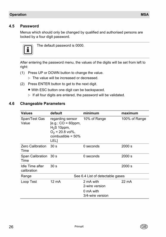
4.5 PasswordMenus which should only be changed by qualified and authorised persons are locked by a four digit password.
After entering the password menu, the values of the digits will be set from left to right:
(1) Press UP or DOWN button to change the value.The value will be increased or decreased.
(2) Press ENTER button to get to the next digit.
With ESC button one digit can be backspaced.If all four digits are entered, the password will be validated.
4.6 Changeable Parameters
The default password is 0000.
Values default minimum maximumSpan/Test Gas Value
regarding sensor [e.g.: CO = 60ppm, H2S 10ppm, O2 = 20.8 vol%, combustible = 50% LEL]
10% of Range 100% of Range
Zero Calibration Time
30 s 0 seconds 2000 s
Span Calibration Time
30 s 0 seconds 2000 s
Idle Time after calibration
30 s 2000 s
Range See 6.4 List of detectable gasesLoop Test 12 mA 2 mA with
2-wire version0 mA with 3/4-wire version
22 mA

OperationMSA
PrimaXGB 27
4.7 Optional HART Module and RelayHART
Introduction"HART" is an acronym for Highway Addressable Remote Transducer. The HART Protocol makes use of the Bell 202 Frequency Shift Keying [FSK] standard to superimpose digital communication signals at a low level on top of the 4 - 20 mA. The HART Protocol provides two simultaneous communication channels: the 4 - 20 mA analog signal and a digital signal. The 4 - 20 mA signal communicates the primary measured value [in the case of a field instrument] using the 4 - 20 mA current loop. Additional device information is communicated using a digital signal that is superimposed on the analog signal. The device is available with an optional HART module or a module with HART and Relays for alarm and failure. It uses the HART Protocol Revision 7 and can only communicate with HART Masters who support revision 7 or higher.
Electrical Installation
Fig. 10 HART ports
For wiring diagrams → chapter 10.6.
The following HART functions are also available:ZERO SPAN Calibration / Oxygen Calibration; ZERO Calibration; Sen-sor Exchange; LCD/LED Test; Loop Test; Range setup; Reset alarm; Readout all measured data and information.
1 Optional HART port
1

MSAOperation
PrimaX28 GB
Relays
Fig. 11 Location of Relay
Fig. 12 Relay Terminals
1 Relay Terminals
Alarm Relay Failure Relay
1 Normally closed energised[NC] 1 Normally closed energised[NC]
2 Common [COM] 2 Common [COM]
3 Normally open energised[NO] 3 Normally open energised[NO]
1
1 32 1 32ALARM FAILURE

OperationMSA
PrimaXGB 29
Relay OperationStartupIf relays are used the alarm threshold will be displayed at startup
Menu Sequence
Relay Operation
[M-11] - Relay Info(1) Press ENTER and select menu 11.
(2) Press ENTER button.
(3) Go through the information with the ENTER button.It shows:
- The alarm threshold and if the alarm is activated with a rising or falling gas con-centration.
- if an alarm would be latched.
- the alarm relay delay time in seconds.
- if the alarm relay is energised at alarm.
- the failure relay delay time in seconds.
- if the failure relay is energised at failure.
Menu item Text Password?M-11 Relay Info NoM-12 Relay Setup YesM-13 RelayTest Yes

MSAOperation
PrimaX30 GB
[M-12] - Relay Setup (1) Press ENTER and select menu 12.
(2) Press ENTER button.
(3) Enter password [→ chapter 4.5].
(4) Set the alarm threshold with the UP or DOWN button.
(5) Press ENTER button.
(6) Set rising or falling alarm option with the UP or DOWN button.
(7) Press ENTER button.
(8) Set if latched with the UP or DOWN button.
(9) Press ENTER button.
(10) Set the alarm relay delay with the UP or DOWN button.
(11) Press ENTER button.
(12) Set alarm relay energised at alarm option with the UP or DOWN button.
(13) Press ENTER button.
(14) Set the failure relay delay with the UP or DOWN button.
(15) Press ENTER button.
(16) Set the failure relay energised at failure option with the UP or DOWN button.
(17) Press ENTER button.
[M-13] - Relay Test(1) Press ENTER and select menu 13.
(2) Press ENTER button.
(3) Enter password [→ chapter 4.5].
(4) The relays are now Switched and can be tested.
(5) Press ENTER button to go back to menu or ESC to go back to measuring mode.

OperationMSA
PrimaXGB 31
Changeable Parameters for Relays
Changeable Paramters with HART
Values default minimum maximumAlarm threshold 30% of Range
[O2 = 20 vol%]5 % of Range 100% of Range
alarm relay energised at alarm
no yes no
latch alarms yes yes noalarming direction O2 decrease;
other increaseIncreasing Decreasing
alarm delay time 0 s 0 s 600 swarning relay energised if warning
no yes no
warning relay delay time 0 s 0 s 600 s
For all parameters which can be changed over keypad see chapter 4.6.For relay parameters which can be changed over keypad see above.
Values default minimum maximumPassword 0000 0000 9999Tag MSA - -Description PrimaX - -Long tag - -Message - -Enable LOC if combustible enable enable disable

MSAOperation
PrimaX32 GB
Output States
Switched: the relay state has switched from the normal state. The normal state can be set to energised if alarm/failure or de-energised if alarm/failure. Normally de-en-ergised if alarm/failure meets the ATEX and SIL requirements.LOC: The PrimaX Gas Monitor has been exposed to a high gas concentration [above the LEL], and there is a possibility that the over-range condition may still ex-ist.
Error Codes
State Failure Relay Alarm RelayNormalStartup Startup state
[default: switched]CalibrationLatched voltage overrange SwitchedLoop not connected SwitchedUnderrange SwitchedOverrange SwitchedError SwitchedSafety critical error SwitchedLOC SwitchedLatched LOC SwitchedAlarm threshold exceed Switched
Display CauseE-40 - E-47 Relay error

MaintenanceMSA
PrimaXGB 33
5 Maintenance5.1 Changing the Sensors
Danger!Remove and reinstall sensors carefully, ensuring that the components are not damaged; otherwise the approval may be adversely affected, wrong readings could occur, and persons relying on this product for their safety could sustain serious personal injury or death.
If changing the sensor, reset the sensor life time counter. To reset the counter → chapter 4.2 M-05.

MSAMaintenance
PrimaX34 GB
Remove Interlock(1) Unscrew the socket head screw.
(2) Remove the interlock.
Remove BayonetJoint(3) Turn the bayonet ring counter-clock-
wise.
(4) Remove the bayonet ring by pulling it down.
Replace Sensor(5) Unplug the sensor carefully.
(6) Plug in the new sensor carefully.
(7) Replace the bayonet ring.
(8) Replace the interlock.

Technical DataMSA
PrimaXGB 35
6 Technical Data6.1 Specifications
PrimaX P PrimaX I
Enclosurealuminium enclosureflameproofIP 66 ingress protection
plastic enclosureintrinsically safeIP 66 ingress protection
Dimensions in mm[Height X Width X Depth]
220 X 162 X 100 220 X 162 X 81
Weight 1.6 kg 1.2 kgHumidity 15 % to 90 % rel. humidity 15 % to 90 % rel. humidityPower supply 19.2 V - 28.0 V 19.2 V - 28.0 VPower consumption 3 W 0.7 WTemperature range [instrument]Temperature range [sensor]
-40 to +70 °C
see sensor
-40 to +70 °C
see sensor
Signal outputHART [option]Relay [option]
4 – 20 mAyesyes
4 – 20 mAyesno
Pressure 80 – 120 kPa 80 – 120 kPaMax. load resistance 300 Ohm 300 OhmAir velocity 0 – 6 m/s 0 – 6 m/s

MSATechnical Data
PrimaX36 GB
6.2 Cable Lengths and Cross-sections
Toxic Gases and Oxygen Sensors with 4 – 20 mA Signal Output[2- wire Sensor]
Catalytic Combustible Gas Sensor with 4 – 20 mA Signal Output[3- wire Sensor]
Toxic Gases and Oxygen Sensors with 4 – 20 mA Signal Output[3- wire Sensor]
Catalytic Combustible Gas Sensor with 4 – 20 mA Signal Output[4- wire Sensor]
Cross-section Max. length at 24 V DC Max. load resistance1.0 mm2 2100 m 300 Ohm
Power supply 24 V DCConfiguration without relay with relay Cross-section 1.0 mm2 762 m 640 mCross-section 1.5 mm2 1280 m 914 mMax. load resistance at signal output 300 Ohm
Cross-section Max. length at 24 V DC Max. load resistance1.0 mm2 3658 m 300 Ohm
Power supply 24 V DCConfiguration without relay with relay Cross-section 1.0 mm2 610 m 457 mCross-section 1.5 mm2 1067 m 762 mMax. load resistance at signal output 300 Ohm
Version Wire Min. supply voltage2-wire 1 mm2 19.2 %3-wire 1.5 mm2 19.2 %4-wire 1.5 mm2 19.2 %

Technical DataMSA
PrimaXGB 37
6.3 Performance Specifications
6.4 List of Detectable Gases
Warm up time Combustible 90 sOX/TOX 30 s
Storage temperature -40 °C to +70 °C or limits of the sensor
Gas Default range Selectable range[s]
Temperature Range
Methane [CH4] 100 % LEL - -40 –70 °CPropane [C3H8] 100 % LEL - -40 – 70 °COxygen [O2] 25 vol. % 10 vol. % -30 – 55 °CCarbon Monoxide [CO] 200 ppm 100 ppm
500 ppm1000 ppm
-20 – 50 °C
Hydrogen Sulphide [H2S] 50 ppm 10 ppm20 ppm100 ppm
-40 – 50 °C
Ammonia [NH3] 100 ppm 50 ppm -20 – 40 °CAmmonia [NH3] 500 ppm 1000 ppm -20 – 40 °CChlorine [Cl2] 10 ppm 5 ppm -20 – 40 °CSulphur Dioxide [SO2] 50 ppm 10 ppm
20 ppm100 ppm
-20 – 50 °C
Hydrogen Cyanide [HCN] 30 ppm 10 ppm20 ppm50 ppm
-40 – 40 °C
Hydrogen Chloride [HCl] 30 ppm 10 ppm20 ppm
-20 – 40 °C
Hydrogen Fluoride [HF] 10 ppm 5 ppm -20 – 40 °CHydrogen [H2] 1000 ppm - -20 – 50 °CNitrogen Dioxide [NO2] 10 ppm 20 ppm
100 ppm-20 – 50 °C

MSATechnical Data
PrimaX38 GB
Nitric Oxide [NO] 100 ppm - -30 – 50 °CPhosphine [PH3] 1 ppm - -20 – 40 °CSilane [SiH4] 50 ppm 20 ppm -20 – 40 °CHydrogen Bromide [HBr] 30 ppm - -20 – 40 °CGermane [GeH4] 2 ppm - -20 – 40 °CFluorine [F2] 1 ppm - -10 – 40 °CDiborane [B2H6] 1 ppm -Bromine [Br2] 10 ppm -Arsine [AsH3] 1 ppm - -20 – 40 °C
Gas Default range Selectable range[s]
Temperature Range

Technical DataMSA
PrimaXGB 39
6.5 Sensor Response to Interferants
Interference factors may differ from sensor to sensor and with life time.It is not advisable to calibrate with interference gases.This table does not claim to be complete. The sensor might also be sen-sitive to other gases.
Gas InterferantOxygen [O2]Carbon Monoxide [CO]Hydrogen Sulphide [H2S] 100 ppm Cl2
-9 ppm100 ppm NO2-21 ppm
100 ppm NO1 ppm
100 ppm HCN1 ppm
100 ppm SO21 ppm
Ammonia [NH3] 20 ppm H2S2 ppm
Ammonia [NH3] 20 ppm H2S2 ppm
20 ppm SO2-40 ppm
Chlorine [Cl2] 1 ppm Br21 ppm
2.4 ppm ClO20.55 ppm
20 ppm H2S0.1 ppm
10 ppm NO24.5 ppm
0.25 ppm O30.11 ppm
Chlorine [Cl2]Exposure to H2S will poison the cell.
1 ppm Br21 ppm
1 ppm ClO20.55 ppm
1 ppm F20.4 ppm
10 ppm NO22 ppm
0.25 ppm O30.05 ppm
20 ppm SO23.5 ppm
Sulphur Dioxide [SO2] 300 ppm CO<3 ppm
5 ppm NO2-5 ppm
Hydrogen Cyanide [HCN] 100 ppm NO-5 ppm
10 ppm NO2-7 ppm

MSATechnical Data
PrimaX40 GB
Hydrogen Chloride [HCl] 100 ppm NH30.1 ppm
0.2 ppm AsH30.7 ppm
5 ppm Cl20.3 ppm
20 range HCN7 ppm
20 range H2S13 ppm
100 range NO45 ppm
10 ppm NO20.3 ppm
0.1 ppm PH30.3 ppm
20 ppm SO28 ppm
Hydrogen Bromide [HBr]Hydrogen [H2] 300 ppm CO
<60 ppm15 ppm H2S<3 ppm
35 ppm NO10 ppm
100 ppm HCN3 ppm
100 ppm C2H480 ppm
Nitrogen Dioxide [NO2] 50 ppm NO2<5 ppm
20 ppm SO2<2 ppm
10 ppm Cl2<15 ppm
400 ppm H2<0.1 ppm
20 ppm H2S<15 ppm
400 ppm CO<0.1 ppm
20 ppm NH3<0.1 ppm
Phosphine [PH3] 100 ppm NH30.1 ppm
1 ppm Cl2-0.07 ppm
0.25 ppm B2H0.18 ppm
5 ppm SiH43.8 ppm
200 ppm HCN0.5 ppm
20 ppm H2S5 ppm
0.1 ppm PH30.13 ppm
20 ppm SO22 ppm
10 ppm NO2-2 ppm
Diborane [B2H6]Bromine [Br2]Arsine [AsH3]Silane [SiH4] 0.2 ppm AsH3
0.2 ppm0.25 ppm B2H0.12 ppm
20 ppm HCN0.5 ppm
2 ppm H2S8 ppm
0.1 ppm PH30.13 ppm
20 ppm SO24 ppm
10 ppm NO-2 ppm
Germane [GeH4]
Gas Interferant

Technical DataMSA
PrimaXGB 41
Nitric oxide [NO] 50 ppm NO<0.5 ppm
20 ppm SO2<-2.5 ppm
10 ppm Cl2100 ppm
400 ppm H2<0.1 ppm
20 ppm H2S<-40 ppm
400 ppm CO<0.1 ppm
20 ppm NH3<0.1 ppm
50 ppm C2H2<0.1 ppm
Hydrogen Fluoride [HF] 1 ppm Cl20.7 ppm
3000 ppm H2<1 ppm
20 ppm SO216 ppm
Fluorine [F2] 0.2 ppm AsH31 ppm
100 ppm CO1 ppm
1 ppm Cl21.4 ppm
0.25 ppm B2H0.4 ppm
1 ppm HCN-3 ppm
1 ppm H2S-2 ppm
10 ppm NO2-19 ppm
0.25 ppm O30.3 ppm
20 ppm SO20.04 ppm
Gas Interferant

MSAApprovals
PrimaX42 GB
7 Approvals7.1 Marking, Certificates and Approvals
According to the Directive 94/9/EC [ATEX]
PrimaX P
Manufacturer: MSA AUER GmbHThiemannstraße 1D-12059 Berlin
Product: PrimaX P
Type of protection: EN 60079-0:2009, EN 60079-1:2007,EN 60079-11:2007, IEC 60079-31:20086
Measuring function for explosion protection: no
Gas: see manual
Marking: Prima X PII 2G Ex d [ia] IIC T4 GaII 2D Ex t [ia] IIIC T130°C Db-40°C ≤ Ta ≤ +70°C
Option: HART Module Connector, only for temporary connection of an intrinsic safe HART Field CommunicatorPo ≤ 220 mW, Uo ≤ 2,7 V, I0 ≤ 140 mA, Lo ≤ 10 µH, Co ≤ 1 nFPi ≤ 5 mW, Ui ≤ 5 V, Ii ≤ 1 mA, Li = 0, Ci = 0
EC-Type Examination Certificate: BVS 10 ATEX E009 XQuality Assurance Notification: 0158Year of Manufacture: see LabelSerial Nr.: see LabelSpecial conditions for safe use: no
EMC Conformance according to the Directive 2004 / 108 / ECEN 50270:2007 Type 2, EN 61000-6-3:2007

ApprovalsMSA
PrimaXGB 43
PrimaX I
Manufacturer: MSA AUER GmbHThiemannstraße 1D-12059 Berlin
Product: PrimaX I
Type of protection: EN 60079-0:2006, EN 60079-11:2007,EN 60079-26:2007, EN 61241-11:2006
Measuring function for explosion protection: no
Gas: see manual
Marking: Prima X III 1G Ex ia IIC T4 GaII 2D Ex ia IIIC T130°C Db-40°C ≤ Ta ≤ +70°C
Pi ≤ 770 mW, Ui ≤ 28 V, Ii ≤ 110 mA, Li = 0, Ci = 0
Option: HART Module Connector, only for temporary connection of an intrinsic safe HART Field CommunicatorPo ≤ 770 mW, Uo ≤ 28 V, I0 ≤ 110 mA, Lo ≤ 10 µH, Co ≤ 1 nFPi ≤ 5 mW, Ui ≤ 5 V, Ii ≤ 1 mA, Li = 0, Ci = 0
EC-Type Examination Certificate: BVS 10 ATEX E009 XQuality Assurance Notification: 0158Year of Manufacture: see LabelSerial Nr.: see LabelSpecial conditions for safe use: It is not allowed to open the key pad cover by
operations at Category II 1G and Group IIC.
EMC Conformance according to the directive 2004 / 108 / ECEN 50270:2007 Type 2, EN 61000-6-3:2007

MSAApprovals
PrimaX44 GB
7.2 Marking and Certificates according to IECEx
PrimaX P
Manufacturer: MSA AUER GmbHThiemannstraße 1D-12059 Berlin
Product: PrimaX P
Type of protection: IEC 60079-0:2007, IEC 60079-1:2007,IEC 60079-11:2006, IEC 60079-31:2009
Measuring function for explosion protection: no
Gas: see manual
Marking: Prima X PEx d [ia] IIC T4 GbEx t [ia] IIIC T130°C Db-40°C ≤ Ta ≤ +70°C
Pi ≤ 770 mW, Ui ≤ 28 V, Ii ≤ 110 mA, Li = 0, Ci = 0
Option: HART Module Connector, only for temporary connection of an intrinsic safe HART Field CommunicatorPo ≤ 200 mW, Uo ≤ 2,7 V, I0 ≤ 140 mA, Lo ≤ 10 µH, Co ≤ 1 nFPi ≤ 5 mW, Ui ≤ 5 V, Ii ≤ 1 mA, Li = 0, Ci = 0
EC-Type Examination Certificate: IECEx BVS 10.xxxx XQuality Assurance Notification: 0158Year of Manufacture: see LabelSerial Nr.: see LabelSpecial conditions for safe use: no

ApprovalsMSA
PrimaXGB 45
PrimaX I
Manufacturer: MSA AUER GmbHThiemannstraße 1D-12059 Berlin
Product: PrimaX I
Type of protection: IEC 60079-0:2007, IEC 60079-11:2006,IEC 60079-26:2006, IEC 61241-11:2005
Measuring function for explosion protection: no
Gas: see manual
Marking: Prima X IEx ia IIC T4 GaEx ia IIIC T130°C Db-40°C ≤ Ta ≤ +70°C
Pi ≤ 770 mW, Ui ≤ 28 V, Ii ≤ 110 mA, Li = 0, Ci = 0
Option: HART Module Connector, only for temporary connection of an intrinsic safe HART Field CommunicatorPo ≤ 770 mW, Uo ≤ 28 V, I0 ≤ 110 mA, Lo ≤ 10 µH, Co ≤ 1 nFPi ≤ 5 mW, Ui ≤ 5 V, Ii ≤ 1 mA, Li = 0, Ci = 0
EC-Type Examination Certificate: IECEx BVS 10. xxxx XQuality Assurance Notification: 0158Year of Manufacture: see LabelSerial Nr.: see LabelSpecial conditions for safe use: It is not allowed to open the key pad cover by
operations at Category II Ga and Group IIC.

MSAAccessories
PrimaX46 GB
8 AccessoriesFor part numbers → chapter 8.5.
8.1 Sensor GardThe sensor gard should be fitted at all times except when using the flow through adapter or duct mount kit.Ambient weather condition can affect the gas mixture inside of the sensor gard. Use sensor gard for functional test only. Calibration cap is recommended for sensor cal-ibration.
8.2 Flow Through AdapterThe flow through adapter is for use with a pumped sampling system.
8.3 Duct Mounting KitGas monitoring in air ducts can be performed by means of this duct mounting kit. When installing, the direction of flow inside the duct must be towards the baffles.The sensor can be calibrated via the gas calibration port, provided the duct is free of all gases to which the sensor will respond. If the duct cannot be gas free, the sen-sor must be removed from the duct during calibration.The calibration port must be sealed again with the locking cap after calibration has been carried out.Calibration should only be carried out with the calibration port if the air velocity is < 5 m/s in the air duct.
Gas inlet/outlet thread: 1/8” NPTGas flow rate: 1.0 l/min
Using the flow through adapter will extend the response time, depend-ing on the gas flow rate.

Spare PartsMSA
PrimaXGB 47
8.4 Pipe Mounting KitThe pipe mounting kit contains clamps and screws to mount the device on pipes and poles.
8.5 Sensor TagThe stainless steel label allows to identify and tag the location or installation of the instrument on the site.
8.6 SunshieldStainless steel plate to protect the transmitter from direct sunlight.
8.7 Universal HART CableUniversal cable that will connect the PrimaX detector to any standard HART hand-held [f.e. Emerson 375] using the HART connector.
9 Spare PartsList of Accessories
PrimaX I Replacement Parts
Description Material Part No.Sensor Gard Plastic 10113033Flow Through Adapter St.St. 316 10113031Duct Mounting Kit St.St. 316 10112790Pipe Mounting Kit St.St. 316 10113032Sensor Tag St.St. 316 10113034Sunshield St.St. 316 10113035Calibration Cap Plastic 10112789Universal HART cable [1.5 m] 10113036
Description Part NoBayonet lock plate & screw 10113042Sensor bayonet & cap 10113048Mounting plate 10113041Lid 10113045Lid screws [set of 4] 10113046

MSASpare Parts
PrimaX48 GB
PrimaX P Replacement Parts
Keyboard cover 10113040Cable gland M25 x 1.5, 7 – 17 mm 10113039
Description Part NoBayonet lock plate & screw 10113050Sensor bayonet and cap 10113058Mounting plate 10113041Lid 10113056Keyboard cover 10113040Cable gland Ex d II CT4 M25 x 1.5 10113038Cable gland Ex d II CT4 ¾“ NPT 10113037
Gas Range [optional] Part No.Catalytic Sensor Combustible Gases [Only PrimaX P version]
100% LEL 10112716
Oxygen [O2] 0–25% vol. [10vol%] 10112718Carbon Monoxide [CO] 200 ppm [100 ppm,
500 ppm, 1000 ppm]711306
Hydrogen Sulphide [H2S] 50 ppm [10 ppm, 20 ppm, 100 ppm]
711307
Ammonia [NH3] 100 ppm [50 ppm] 10080225Ammonia [NH3] 1000 ppm [500 ppm] 10112719Chlorine [CL2] 10 ppm [5 ppm] 10112720Sulphur Dioxide [SO2] 50 ppm [10 ppm, 20 ppm,
100 ppm]10080223
Hydrogen Cyanide [HCN] 30 ppm [10 ppm, 20 ppm, 50 ppm]
10080220
Hydrogen Chloride [HCl] 30 ppm [10 ppm, 20 ppm] 10112721Hydrogen Fluoride [HF] 10 ppm [5 ppm] 10112722Hydrogen [H2] 1000 ppm 10112723Nitrogen Dioxide [NO2] 10 ppm [20 ppm, 100 ppm] 10080224Nitrogen Oxide [NO] 100 ppm 10112724
Description Part No

Spare PartsMSA
PrimaXGB 49
Phosphine [PH3 1 ppm 10080226Silane [SiH4] 50 ppm [20 ppm] available on
requestHydrogen Bromide [HBr] 30 ppm available on
requestGermane [GeH4] 2 ppm available on
requestFluorine [F2] 1 ppm available on
requestDiborane [B2H6] 1 ppm available on
requestBromine [Br2] 10 pmm available on
requestArsine [AsH3] 1 ppm available on
request
Gas Range [optional] Part No.
Electrochemical sensors should only ordered for immediate replace-ment.The storage temperature should be in the range of +5° C to +12° C. Disposal of electrochemical sensors has to be carried out pro-fessionally

MSAAppendix
PrimaX50 GB
10 Appendix10.1 Output States
LOC: The PrimaX Gas Monitor has been exposed to a high gas concentration [above the LEL], and there is a possibility that the over-range condition may still ex-ist.
Display LED colour State Signal current DefaultGreen Normal 4 – 20 mAYellow [flashing] Startup Service current 3 mA Yellow [flashing] Calibration Service current 3 mA
CAL Yellow Calibration invalid Service current 3 mAVCC Yellow Latched voltage
overrange [confirm on device]
Service current 3 mA
Loop Yellow Loop not connected [PrimaX P]
LO Yellow Underrange 3.8 – 4 mAHI Yellow Overrange 20 – 20.5 mAE-XX Yellow Error Error current 2 mAE-XX Yellow Safety critical error Open loop
- 0 mA PrimaX P
- <2 mA PrimaX ILOC Red LOC [if combustible] 20.5 mALOC Red [flashing] Latched LOC
[if combustible]20.5 mA

AppendixMSA
PrimaXGB 51
10.2 Calibration Faults
10.3 Error Codes
If an error code is displayed, the normal operation of the device is not possible.If the error code is still shown after a reset, the device could be defective.
Sensor errors [E-20 – E-29] could be cleared by checking if the sensor is well con-nected, or by changing the sensor, or also by resetting the device.
Display CauseFault -1 Zero not stableFault -2 Zero too lowFault -3 Zero too highFault -4 Span not stableFault -5 Span too lowFault -6 Span too highFault -7 Not enough resolutionFault -8 Catalytic sensor values out of technical specification
If an error is detected, the error code E, followed by a nu-meric code and a short description, will be displayed.In this case the normal operation mode of the device will not respond to gas and the output signal current will be the ERROR value [default 2 mA].
Display CauseE-01 - E-19 Latched Hardware/Software ErrorE-20 - E-29 Sensor Cell errorE-30 - E-39 Unlatched Hardware/Software ErrorE-48 Device supply too highE-49 Device supply too low
For latched errors E-01 to E-29 pressing any key initiates a reset.

MSAAppendix
PrimaX52 GB
10.4 TimeoutThe automatic calibration has a timeout of 4 minutes. The manual calibration has a timeout of 60 minutes [M-01, M-02]. Any test procedure [M-06, M-07] has a timeout of 15 minutes. Anywhere else in the menu the timeout is 2 minutes, if no button is pressed.
10.5 Mechanical Installation
Dimensions
Fig. 13 Outline dimensions Prima X P
Fig. 14 Outline dimensions Prima X I

AppendixMSA
PrimaXGB 53
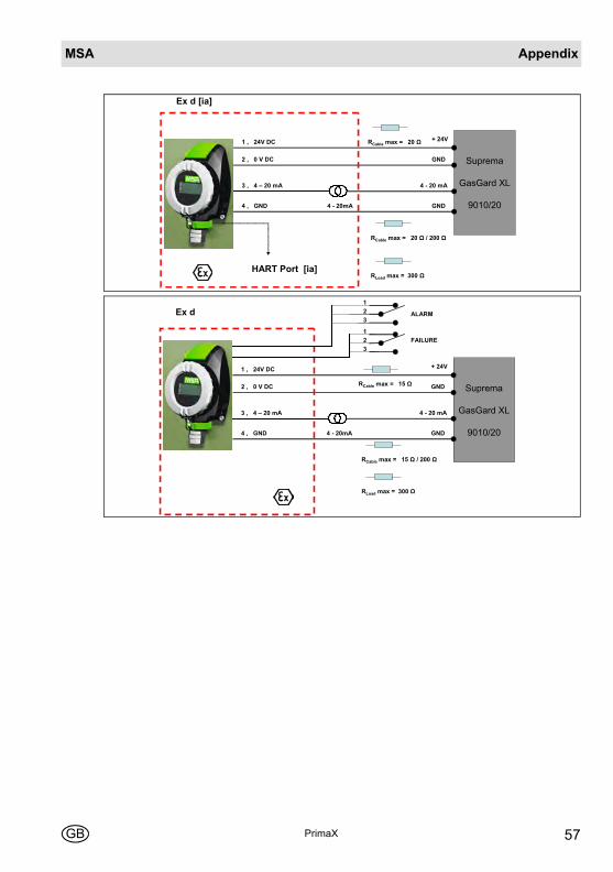
10.6 Wiring DiagramsThe HART communications require a minimum of 250 ohms resistance in the 4 – 20 mA loop.
PrimaX I, Ex ia, Intrinsically Safe
Controller
Suprema
GasGard XL
9010/20
+ 24V
4 - 20mA
-
+ 1
- 2
RCable max = 70 Ω RLoad max = 300 Ω
Controller
Suprema
GasGard XL
9010/20
+ 24V
4 - 20mA
-
HART ports
+ 1
- 2
RCable max = 70 Ω RLoad max = 300 Ω
Knick WG 21 A7
Controller
Suprema
GasGard XL
9010/20
+ 1
- 2
+ 1
- 2
+ 5
- 6
7 8
24V AC/DC
+24V
0 V4 – 20mA
RCable max = 300 Ω

MSAAppendix
PrimaX54 GB
PEPPERL+FUCHS KFD2-STC4-Ex1
Controller
Suprema
GasGard XL
9010/20
+ 1
- 2
+ 1
- 3
+ 8
- 7
+ 14 - 15
24V DC
+24V
0 V4-20mA
RCable max = 200 Ω
MTL MTL 5541/S
Controller
Suprema
GasGard XL
9010/20
+ 1
- 2
+ 2
- 1
+ 12
- 11
+ 14 - 13
24V DC
+24V
0 V4-20mA
RCable max = 200 Ω
STAHL 9160/13-11-11
Controller
Suprema
GasGard XL
9010/20
+ 1
- 2
+ 12
- 10
+ 1
- 2
+ 7 - 9
24V DC
+24V
0 V4-20mA
RCable max = 220 Ω
STAHL 9160/13-10-11
Controller
Suprema
GasGard XL
9010/20
+ 1
- 2
+ 12
- 10
+ 1
- 2
+24V
-
4-20mA
RCable max = 220 Ω

AppendixMSA
PrimaXGB 55
PrimaX P, Ex d, Flameproof
Suprema
GasGard XL
9010/20
Ex d
+ 24V
4 - 20mA
4 - 20 mA
2 , 0 V DC
3 , 4 – 20 mA
RCable max = 35 Ω
RLoad max = 300 Ω
GND
1 , 24V DC
Suprema
GasGard XL
9010/20
Ex d
+ 24V
4 - 20mA
4 - 20 mA
2 , 0 V DC
3 , 4 – 20 mA
RCable max = 35 Ω
RLoad max = 300 Ω
GND
1 , 24V DC
Suprema
GasGard XL
9010/20
Ex d [ia]
+ 24V
4 - 20mA
4 - 20 mA
2 , 0 V DC
3 , 4 – 20 mA
RCable max = 35 Ω
RLoad max = 300 Ω
GND
1 , 24V DC
HART Ports [ia]

MSAAppendix
PrimaX56 GB
Suprema
GasGard XL
9010/20
Ex d
+ 24V
4 - 20mA
4 - 20 mA
2 , 0 V DC
3 , 4 – 20 mA
RCable max = 25 Ω
RLoad max = 300 Ω
GND
1 , 24V DC
RELAIS OPTION
ALARM
FAILURE
321
321
Suprema
GasGard XL
9010/20
Ex d
+ 24V
4 - 20mA
4 - 20 mA
2 , 0 V DC
3 , 4 – 20 mA
RCable max = 20 Ω
RLoad max = 300 Ω
GND
1 , 24V DC
4 , GND GND
RCable max = 20 Ω / 200 Ω
Suprema
GasGard XL
9010/20
Ex d
+ 24V
4 - 20mA
4 - 20 mA
2 , 0 V DC
3 , 4 – 20 mA
RLoad max = 300 Ω
GND
1 , 24V DC
4 , GND GND
RCable max = 20 Ω
RCable max = 20 Ω / 200 Ω
AppendixMSA
PrimaXGB 57
Suprema
GasGard XL
9010/20
Ex d [ia]
+ 24V
4 - 20mA
4 - 20 mA
2 , 0 V DC
3 , 4 – 20 mA
RLoad max = 300 Ω
GND
1 , 24V DC
4 , GND GND
HART Port [ia]
RCable max = 20 Ω / 200 Ω
RCable max = 20 Ω
Suprema
GasGard XL
9010/20
Ex d
+ 24V
4 - 20mA
4 - 20 mA
2 , 0 V DC
3 , 4 – 20 mA
RCable max = 15 Ω
RLoad max = 300 Ω
GND
1 , 24V DC
4 , GND GND
ALARM
FAILURE
321
321
RCable max = 15 Ω / 200 Ω

Thank you for reading this data sheet.
For pricing or for further information, please contact us at our UK Office, using the details below.
UK OfficeKeison Products,
P.O. Box 2124, Chelmsford, Essex, CM1 3UP, England.Tel: +44 (0)330 088 0560Fax: +44 (0)1245 808399
Email: [email protected]
Please note - Product designs and specifications are subject to change without notice. The user is responsible for determining the suitability of this product.