OPERATING MANUAL - Masgrup
10
Revision No: 02 July/2018 Gear Pumps YKF SERIES OPERATING MANUAL
Transcript of OPERATING MANUAL - Masgrup

Revision No: 02 July/2018
Gear Pumps
YKF SERIES
OPERATING MANUAL
Revision No: 02
July/2018
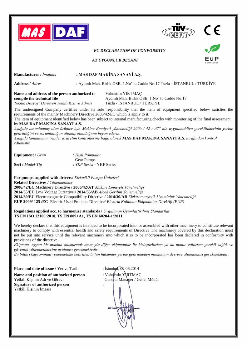
EC DECLARATION OF CONFORMITY
AT UYGUNLUK BEYANI
Manufacturer / İmalatçı : MAS DAF MAKİNA SANAYİ A.Ş.
Address / Adres : Aydınlı Mah. Birlik OSB. 1.No’ lu Cadde No:17 Tuzla - İSTANBUL / TÜRKİYE
Name and address of the person authorized to
compile the technical file
Teknik Dosyayı Derleyen Yetkili Kişi ve Adresi
Vahdettin YIRTMAÇ
Aydınlı Mah. Birlik OSB. 1.No’ lu Cadde No:17
Tuzla - İSTANBUL / TÜRKİYE
The undersigned Company certifies under its sole responsibility that the item of equipment specified below satisfies the
requirements of the mainly Machinery Directive 2006/42/EC which is apply to it.
The item of equipment identified below has been subject to internal manufacturing checks with monitoring of the final assessment
by MAS DAF MAKİNA SANAYİ A.Ş.
Aşağıda tanımlanmış olan ürünler için Makine Emniyeti yönetmeliği 2006 / 42 / AT’ nin uygulanabilen gerekliliklerinin yerine
getirildiğini ve sorumluluğun alınmış olunduğunu beyan ederiz.
Aşağıda tanımlanan ürünler iç üretim kontrollerine bağlı olarak MAS DAF MAKİNA SANAYİ A.Ş. tarafından kontrol
edilmiştir.
Equipment / Ürün : Dişli Pompalar
Gear Pumps
Seri / Model-Tip : YKF Serisi - YKF Series
For pumps supplied with drivers/ Elektrikli Pompa Üniteleri
Related Directives / Yönetmelikler
2006/42/EC Machinery Directive / 2006/42/AT Makine Emniyeti Yönetmeliği
2014/35/EU Low Voltage Directive / 2014/35/AB Alçak Gerilim Yönetmeliği
2014/30/EU Electromagnetic Compatibility Directive / 2014/30/AB Elektromanyetik Uyumluluk Yönetmeliği
EUP 2009/ 125 /EC Electric Used Products Directive/ Elektrik Kullanan Ekipmanlar Direktifi (EUP)
Regulations applied acc. to harmonize standards / Uygulanan Uyumlaştırılmış Standartlar
TS EN ISO 12100:2010, TS EN 809+A1, TS EN 60204-1:2011.
We hereby declare that this equipment is intended to be incorporated into, or assembled with other machinery to constitute relevant
machinery to comply with essential health and safety requirements of Directive The machinery covered by this declaration must
not be put into service until the relevant machinery into which it is to be incorporated has been declared in conformity with
provisions of the directive.
Ekipman, uygun bir makina oluşturmak amacıyla diğer ekipmanlar ile birleştirilirken ya da monte edilirken gerekli sağlık ve
güvenlik yönetmeliklerine uyulması gerekmektedir.
Bu bildiri kapsamında yönetmelikte belirtilen bütün hükümler yerine getirilmeden makinanın devreye alınmaması gerekmektedir.
Place and date of issue / Yer ve Tarih : İstanbul, 02.06.2014
Name and position of authorized person
Yetkili Kişinin Adı ve Görevi
: Vahdettin YIRTMAÇ
General Manager / Genel Müdür
Signature of authorized person
Yetkili Kişinin İmzası :
Mas Grup
1
TABLE OF CONTENTS Page No
Introduction 1 1. General 1
1.1. Acceptance, Commissioning and Storing 1 1.1.1. Acceptance 1 1.1.2. Commissioning 1
1.2. Safety 1 1.3. Pump Coding 2 1.4. Function and Operation Principles 2
1.4.1. Operating Principle 2 1.4.2. Rotation Directions 2
1.5. Standard Parts of the Pump 3 2. Technical Information 4
2.1. Mechanical Properties 4 2.2. Pump Versions 4
3. Assembly and Maintenance 4 3.1. General 4
4. Installation and Pipeline 4 4.1. Start-up (Commissioning) 5 4.2. Routine Checks 5
4.2.1. By-Pass task 5 4.2.2. Circuit By Pass 5 4.2.3. Cover-jacketed pumps 5
5. Seals 5 5.1. Pumps with soft seal 5 5.2. Rotatherm seal 6 5.3. Mechanical seal 6 5.4. Micrometric drum adjustment 6
6. Possible Failures, Causes, Solutions 7
INTRODUCTION
1. GENERAL
MAS Pompa YKF series pumps are the pumps with internal eccentric gears, spur gears, helical gears, and pallet gears. Pumps with internal eccentric gear are manufactured by Yıldız Pompa and marketed through our firm and authorized distributors. This operation manual contains the necessary information for geared pumps and should be read thoroughly before assembly, servicing, and maintenance. The manual should be kept at a place where the user can easily access.
You should not use your pump for purposes other than the specified ones without contacting Yıldız Pompa and its authorized dealers. Liquids not suitable for the pump may damage the pump and
lead to personal injuries. Yıldız Pompa does not take any responsibilities for the repair and modification works made by the user or by any other unauthorized people. 1.1. Acceptance, Commissioning and Storing 1.1.1. Acceptance Remove all the packaging material after delivery. After reception, check the provided materials for damages and make sure that the name and type information are the same as your order and the packaging label. In case there is damage or missing parts, a report should be written and submitted to the transporter. Yıldız Pompa or its dealers should be informed about this situation. The serial number is written on the label on the pump. When you contact Yıldız Pompa, always indicate this number.
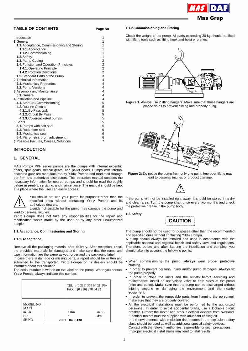
1.1.2. Commissioning and Storing Check the weight of the pump. All parts exceeding 20 kg should be lifted with lifting tools such as lifting hook and hoist or cranes.
Figure 1. Always use 2 lifting hangers. Make sure that these hangers are
placed so as to prevent sliding and properly hung.
Figure 2: Do not tie the pump from only one point. Improper lifting may
lead to personal injuries or product damage.
If the pump will not be installed right away, it should be stored in a dry and clean area. Turn the pump shaft once every two months and check the protective grease in the pump body. 1.2. Safety
CAUTION
The pump should not be used for purposes other than the recommended and specified ones without contacting Yıldız Pompa. A pump should always be installed and used in accordance with the applicable national and regional health and safety laws and regulations. Therefore, before and after Starting the installation and pumping, you should take into account the following points: When commissioning the pump, always wear proper protective
clothing.
In order to prevent personal injury and/or pump damages, always fix the pump properly.
In order to close the inlets and the outlets before servicing and maintenance, install an open/close valve to both sides of the pump (inlet and outlet). Make sure that the pump can be discharged without injuring anyone or damaging the environment and the nearby equipment.
In order to prevent the removable parts from harming the personnel, make sure that they are properly covered.
All the electrical installations must be performed by the authorized personnel. In order to avoid accidental Starts, use a lockable circuit breaker. Protect the motor and other electrical devices from overload. Electrical motors must be supplied with abundant cooling air. In the environments with explosion risk, motors in the explosion-safety class should be used as well as additional special safety devices. Contact with the relevant authorities responsible for such precautions. Improper electrical installations may lead to fatal results.
TEL : (0 216) 378 64 21 Pbx
FAX : (0 216) 378 64 22
MODEL NO MAYİ
m 3/h
HP SR.NO
: :
: / Hm m SS.
: / d/d
: 2007 04 8138
Mas Grup
2
Powders, liquids, and gases that might cause overheating, short-circuit, corrosion damage, and fire should be kept away from the motor and other equipments. If the pump is used to pump liquids hazardous to people and environment, then an appropriate container, in which the leaking liquid shall be contained, should be used.
If the temperature of the system or system parts exceeds 60 ºC, then these should be marked with a warning sign “HOT SURFACE” in order to avoid burning risks.
The pump should not be exposed to rapid and sudden temperature changes in the liquid without pre-heating/pre-cooling. Cleaning a hot pump with cold water is absolutely forbidden. Major temperate changes may cause crack formation or explosion that might lead to various personal injuries.
The pump should absolutely not be operated above the rated performance.
Power should be cut off before intervening the system and the pump; and the Start button should be locked. When servicing the inside of the pump, follow the disassembly/assembly instructions. If these instructions are not followed, the pump or the pump parts may be destroyed. This will also void the warranty.
Do not use the pump dry. If there is a risk of dry operation, install a protection system against dry operation in order to avoid serious damages.
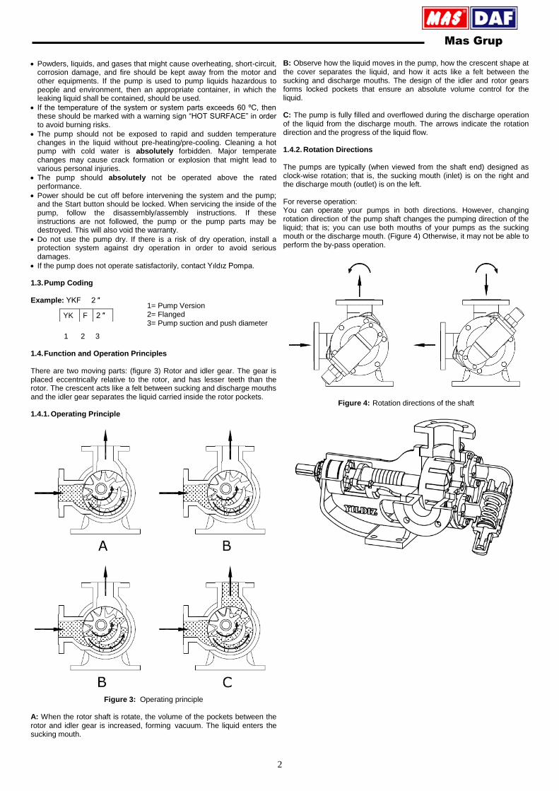
If the pump does not operate satisfactorily, contact Yıldız Pompa. 1.3. Pump Coding
Example: YKF 2 ″
1 2 3 1.4. Function and Operation Principles
There are two moving parts: (figure 3) Rotor and idler gear. The gear is placed eccentrically relative to the rotor, and has lesser teeth than the rotor. The crescent acts like a felt between sucking and discharge mouths and the idler gear separates the liquid carried inside the rotor pockets.
1.4.1. Operating Principle
Figure 3: Operating principle
A: When the rotor shaft is rotate, the volume of the pockets between the rotor and idler gear is increased, forming vacuum. The liquid enters the sucking mouth.
B: Observe how the liquid moves in the pump, how the crescent shape at the cover separates the liquid, and how it acts like a felt between the sucking and discharge mouths. The design of the idler and rotor gears forms locked pockets that ensure an absolute volume control for the liquid. C: The pump is fully filled and overflowed during the discharge operation of the liquid from the discharge mouth. The arrows indicate the rotation direction and the progress of the liquid flow. 1.4.2. Rotation Directions The pumps are typically (when viewed from the shaft end) designed as clock-wise rotation; that is, the sucking mouth (inlet) is on the right and the discharge mouth (outlet) is on the left. For reverse operation: You can operate your pumps in both directions. However, changing rotation direction of the pump shaft changes the pumping direction of the liquid; that is; you can use both mouths of your pumps as the sucking mouth or the discharge mouth. (Figure 4) Otherwise, it may not be able to perform the by-pass operation.
Figure 4: Rotation directions of the shaft
YK F 2 ″
1= Pump Version 2= Flanged 3= Pump suction and push diameter

Mas Grup
3
1.5. Standard Parts of the Pump
Figure 5: List of Spare Parts
1 Lock Nut 14 Idler Bushing
2 Ring 15 Cover Pin
3 Adjusting Nut 16 Cover
4 Seal 17 Screw
5 Bearing 18 Nut
6 Shaft 19 Stud
7 Packing Press 20 Internal Relief Valve
8 Seal 21 Valve
9 Bracket Bushing 22 Spring
10 Bracket 23 Washer
11 Casing 24 Bypass Head
12 Rotor 25 Bypass Screw
13 Idler 26 Screw Cover

Mas Grup
4
2. TECHNICAL INFORMATION 2.1. Material Properties Pump Body and Gears: Cast (pig) iron, steel cast, stainless AISI 304 -
316 cast, spheroid cast Bearings: Snbz 12 bronze, bearing, carbon graphite,
silicon carbide, hard metal plating Sealing: Soft seal, rotatherm seal, mechanical seal 2.2. Pump Versions SERIES: Our pumps from 1 ″ to 8 ″ are used in fuel oil service tanks, oil tankers, gas oil tankers, fuel oil tankers, small hot-oil circulations, transfer works of all viscose, semi-viscose industrial liquids, and pharmaceutical, chemical, detergent, and food industries. General maximum liquid temperature (-20 ÷ 200 ºC)
3. ASSEMBLY AND MAINTENANCE 3.1. General
The pump unit should be completely mounted in its place.
A lockable circuit breaker should be installed to the pump unit.
Turn off the power before any maintenance on the pump or the system and lock out the Starting device to prevent accidental Starts. The pumps should be disconnected from the pipeline and the electrical circuit. If the pump is used for corrosive and hazardous liquids, empty the system and the pump.
Always connect an appropriate safety valve or another safety device in order to prevent the overload of the pump and the pump system.
The pump may be installed horizontally or vertically, but the connection mouths should look downwards unless the storage tank is placed over the pump level (overflow pipe).
4. INSTALLATION AND PIPELINE After the pipes are installed, it should be checked that the pump and the propulsion motor pump and motor shafts are at the same level and the base bolts are tightened. The smallest deviations must be corrected. The gap between the two halves of the coupling should be approximately.
Figure 6
Check that the treated surfaces around the coupling (a) are aligned from four different points with a steel ruler. The length of the coupling should be equal and the outer surfaces of the coupling halves (b) are measured from four different points.
Figure 7: Coupling Adjustment
Check that all the pipelines are aligned properly with the pump mouths and the stresses are removed in order to prevent load transfer to the pump. Use pipes made of proper material and measures. All the pipelines should be completely cleaned. Seal the pipe connections with an appropriate material.
Before tightening, check that the pipe flanges are fitting the pump flanges
1.Avoid this shape.
2.If necessary, prefer a horizontal crank as seen in the figure instead of a
vertical one
3.In order to prevent air pockets formation, give a proper slope to the
sucking pipe as seen in the figure.
4.This shape should be preferred. Because the liquid will be close to the pump.
Figure 8
b
a
Mas Grup
5
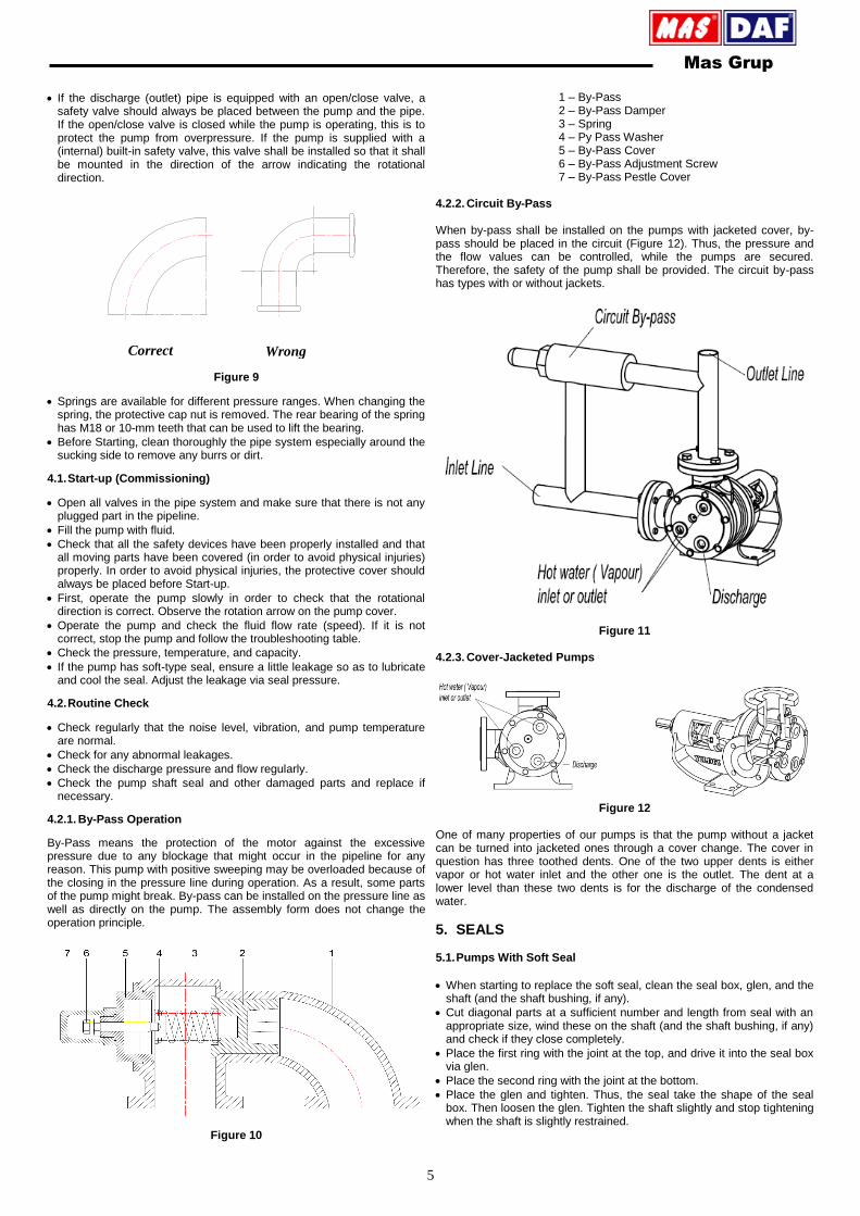
If the discharge (outlet) pipe is equipped with an open/close valve, a safety valve should always be placed between the pump and the pipe. If the open/close valve is closed while the pump is operating, this is to protect the pump from overpressure. If the pump is supplied with a (internal) built-in safety valve, this valve shall be installed so that it shall be mounted in the direction of the arrow indicating the rotational direction.
Figure 9
Springs are available for different pressure ranges. When changing the spring, the protective cap nut is removed. The rear bearing of the spring has M18 or 10-mm teeth that can be used to lift the bearing.
Before Starting, clean thoroughly the pipe system especially around the sucking side to remove any burrs or dirt.
4.1. Start-up (Commissioning)
Open all valves in the pipe system and make sure that there is not any plugged part in the pipeline.
Fill the pump with fluid.
Check that all the safety devices have been properly installed and that all moving parts have been covered (in order to avoid physical injuries) properly. In order to avoid physical injuries, the protective cover should always be placed before Start-up.
First, operate the pump slowly in order to check that the rotational direction is correct. Observe the rotation arrow on the pump cover.
Operate the pump and check the fluid flow rate (speed). If it is not correct, stop the pump and follow the troubleshooting table.
Check the pressure, temperature, and capacity.
If the pump has soft-type seal, ensure a little leakage so as to lubricate and cool the seal. Adjust the leakage via seal pressure.
4.2. Routine Check
Check regularly that the noise level, vibration, and pump temperature are normal.
Check for any abnormal leakages.
Check the discharge pressure and flow regularly.
Check the pump shaft seal and other damaged parts and replace if necessary.
4.2.1. By-Pass Operation
By-Pass means the protection of the motor against the excessive pressure due to any blockage that might occur in the pipeline for any reason. This pump with positive sweeping may be overloaded because of the closing in the pressure line during operation. As a result, some parts of the pump might break. By-pass can be installed on the pressure line as well as directly on the pump. The assembly form does not change the operation principle.
Figure 10
1 – By-Pass 2 – By-Pass Damper 3 – Spring 4 – Py Pass Washer 5 – By-Pass Cover 6 – By-Pass Adjustment Screw 7 – By-Pass Pestle Cover
4.2.2. Circuit By-Pass When by-pass shall be installed on the pumps with jacketed cover, by-pass should be placed in the circuit (Figure 12). Thus, the pressure and the flow values can be controlled, while the pumps are secured. Therefore, the safety of the pump shall be provided. The circuit by-pass has types with or without jackets.
Figure 11 4.2.3. Cover-Jacketed Pumps
Figure 12
One of many properties of our pumps is that the pump without a jacket can be turned into jacketed ones through a cover change. The cover in question has three toothed dents. One of the two upper dents is either vapor or hot water inlet and the other one is the outlet. The dent at a lower level than these two dents is for the discharge of the condensed water.
5. SEALS 5.1. Pumps With Soft Seal
When starting to replace the soft seal, clean the seal box, glen, and the shaft (and the shaft bushing, if any).
Cut diagonal parts at a sufficient number and length from seal with an appropriate size, wind these on the shaft (and the shaft bushing, if any) and check if they close completely.
Place the first ring with the joint at the top, and drive it into the seal box via glen.
Place the second ring with the joint at the bottom.
Place the glen and tighten. Thus, the seal take the shape of the seal box. Then loosen the glen. Tighten the shaft slightly and stop tightening when the shaft is slightly restrained.
Correct Wrong
Mas Grup
6
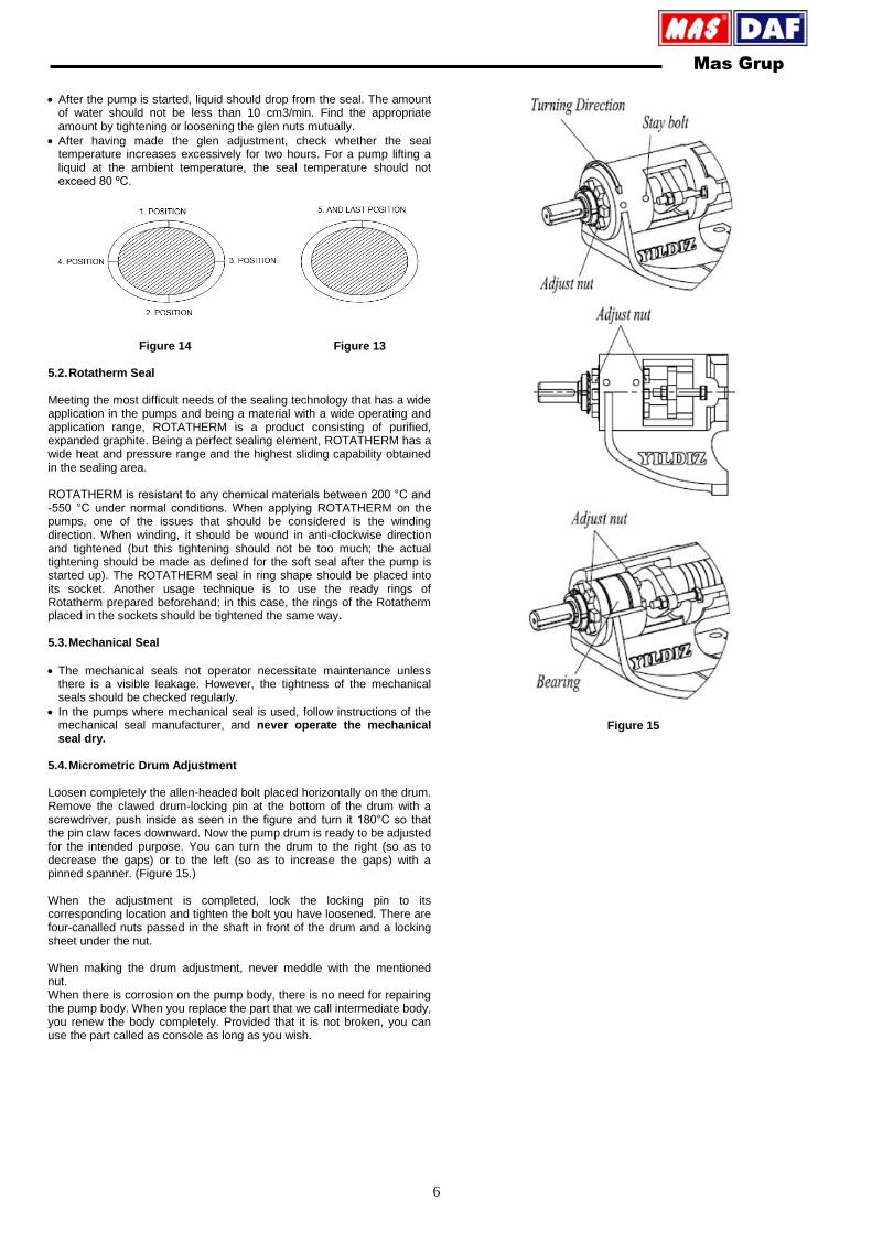
After the pump is started, liquid should drop from the seal. The amount of water should not be less than 10 cm3/min. Find the appropriate amount by tightening or loosening the glen nuts mutually.
After having made the glen adjustment, check whether the seal temperature increases excessively for two hours. For a pump lifting a liquid at the ambient temperature, the seal temperature should not exceed 80 ºC.
Figure 14 Figure 13
5.2. Rotatherm Seal Meeting the most difficult needs of the sealing technology that has a wide application in the pumps and being a material with a wide operating and application range, ROTATHERM is a product consisting of purified, expanded graphite. Being a perfect sealing element, ROTATHERM has a wide heat and pressure range and the highest sliding capability obtained in the sealing area. ROTATHERM is resistant to any chemical materials between 200 °C and -550 °C under normal conditions. When applying ROTATHERM on the pumps, one of the issues that should be considered is the winding direction. When winding, it should be wound in anti-clockwise direction and tightened (but this tightening should not be too much; the actual tightening should be made as defined for the soft seal after the pump is started up). The ROTATHERM seal in ring shape should be placed into its socket. Another usage technique is to use the ready rings of Rotatherm prepared beforehand; in this case, the rings of the Rotatherm placed in the sockets should be tightened the same way. 5.3. Mechanical Seal
The mechanical seals not operator necessitate maintenance unless there is a visible leakage. However, the tightness of the mechanical seals should be checked regularly.
In the pumps where mechanical seal is used, follow instructions of the mechanical seal manufacturer, and never operate the mechanical seal dry.
5.4. Micrometric Drum Adjustment Loosen completely the allen-headed bolt placed horizontally on the drum. Remove the clawed drum-locking pin at the bottom of the drum with a screwdriver, push inside as seen in the figure and turn it 180°C so that the pin claw faces downward. Now the pump drum is ready to be adjusted for the intended purpose. You can turn the drum to the right (so as to decrease the gaps) or to the left (so as to increase the gaps) with a pinned spanner. (Figure 15.) When the adjustment is completed, lock the locking pin to its corresponding location and tighten the bolt you have loosened. There are four-canalled nuts passed in the shaft in front of the drum and a locking sheet under the nut.
When making the drum adjustment, never meddle with the mentioned nut. When there is corrosion on the pump body, there is no need for repairing the pump body. When you replace the part that we call intermediate body, you renew the body completely. Provided that it is not broken, you can use the part called as console as long as you wish.
Figure 15
Mas Grup
7
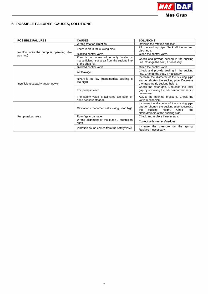
6. POSSIBLE FAILURES, CAUSES, SOLUTIONS
POSSIBLE FAILURES CAUSES SOLUTIONS
No flow while the pump is operating. (No pushing)
Wrong rotation direction. Reverse the rotation direction.
There is air in the sucking pipe. Fill the sucking pipe. Suck all the air and discharge.
Blocked control valve. Clean the control valve.
Pump is not connected correctly (sealing is not sufficient), sucks air from the sucking line or the shaft felt.
Check and provide sealing in the sucking line. Change the seal, if necessary.
Insufficient capacity and/or power
Blocked control valve. Clean the control valve.
Air leakage Check and provide sealing in the sucking line. Change the seal, if necessary.
NPSH is too low (manometrical sucking is too high)
Increase the diameter of the sucking pipe and /or shorten the sucking pipe. Decrease the manometric sucking height.
The pump is worn Check the rotor gap. Decrease the rotor gap by removing the adjustment washers if necessary.
The safety valve is activated too soon or does not shut off at all.
Adjust the opening pressure. Check the valve mechanism
Pump makes noise
Cavitation - manometrical sucking is too high
Increase the diameter of the sucking pipe and /or shorten the sucking pipe. Decrease the sucking height. Check the filters/drainers at the sucking side.
Rotor/ gear damage Check and replace if necessary.
Wrong alignment of the pump / propulsion shaft
Correct with washers/wedges.
Vibration sound comes from the safety valve Increase the pressure on the spring. Replace if necessary.

www.masgrup.com [email protected]
Mas Grup
Head Office / Center Service:
Aydınlı Mah. Birlik OSB. 1.No’lu Cadde No:17 Tuzla - İSTANBUL / TURKEY
Tel: +90 (216) 456 47 00 pbx Fax: +90 (216) 455 14 24
Ankara Regional Directorate:
Aşağı Öveçler Mah. 1329 Sok. No:6/9 Öveçler ANKARA / TURKEY
Tel: +90 (312) 472 81 60-67 Fax: +90 (312) 472 82 51
Factory:
1. Organize Sanayi Bölgesi Parsel 249/5 Beyköy - DÜZCE / TURKEY
Tel: +90 (380) 553 73 88 Fax: +90 (380) 553 71 29