

Operating & Maintenance Manual - Power Towers | Low … Manual UK.pdf · Input Voltage: 90-265V AC...
24
Operating & Maintenance Manual
Transcript of Operating & Maintenance Manual - Power Towers | Low … Manual UK.pdf · Input Voltage: 90-265V AC...

Operating &Maintenance Manual

CONTENTS
Operating Specifications 3
Working Envelope Diagram 3
Do’s and Don’ts 4
Primary Components 5
Operating Procedures (Incl. Emergency Operation) 6-8
Pre-operation checks
Normal Operation: Lift functions, Drive functions
Emergency Operation: Ground and Basket
Maintenance Procedures 9-13
Storage 14
Key Spare Parts 15-18
Electrical Circuit Diagram 19
Hydraulic Circuit Diagram 20
Warranty Terms 21
2
CONTENTS
INTRODUCTION
The Power Tower Nano SP Zero is designed to be a simple, safe and efficient self-propelled alternative to push-around platforms or traditional scaffold tower or podium steps. It can be used for many applications including construction and maintenance where the convenience and efficiency of using a self-propelled platform is preferred. The Nano SP Zero is ideal for working on raised access flooring or other delicate flooring due to its low overall weight and low point loading.
The Nano SP Zero is suitable for any application provided it is used within its operating parameters and should always be used on flat, level and hard surfaces such as concrete. If used for hazardous applications such as shot-blasting, welding, paint spraying or with any other hazardous materials, measures must be taken to ensure the Nano SP Zero does not become damaged in any way that may impair safety or reliability. Additional protection for the operator will be required in some cases, which is the responsibility of the operator and the operator’s employer.
The purpose of this manual is to provide essential basic information required to operate and carry out routine maintenance for the Nano SP Zero. It should be followed by anybody giving familiarisation training for the Nano SP Zero. We recommend any operator of the Nano SP Zero should also have had formal certificated training, such as IPAF category 3A, in addition to Nano SP Zero specific familiarisation.
OPERATING SPECIFICATIONS
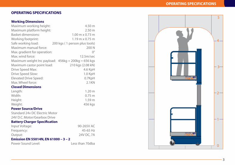
Working DimensionsMaximum working height: 4.50 mMaximum platform height: 2.50 mBasket dimensions: 1.00 m x 0.73 mWorking footprint: 1.19 m x 0.75 mSafe working load: 200 kgs ( 1 person plus tools)Maximum manual force: 200 NMax. gradient for operation: 0°Max. wind force: 12.5m/sec Maximum weight Inc payload: 456kg + 200kg = 656 kgsMaximum castor point load: 210 kgs (2.08 kN)Drive Speed Max: 4.6 KpHDrive Speed Slow: 1.0 KpHElevated Drive Speed: 0.7KpHMax. Wheel force: 2.1KNClosed DimensionsLength: 1.20 mWidth: 0.75 mHeight: 1.59 mWeight: 456 kgsPower Source/DriveStandard 24v DC Electric Motor24V D.C. Motor/Gearbox DriveBattery Charger SpecificationInput Voltage: 90-265V ACFrequency: 45-65 HzOutput: 24V DC, 7AEmission EN 55014N, EN 61000 – 3 – 2Power Sound Level: Less than 70dba
OPERATING SPECIFICATIONS
3

DO’S and DON’TS
4
DO’S
1. Read and adhere to the instructions both on the machine, in the Instruction Guide and Operator Manual.
2. Ensure pre-operation checks and operations are carried out in the manner described.
3. Use only on hard, level surfaces able to support the weight of the machine (e.g. concrete floor, tiled floor, hard wood floor).
4. Ensure operator is fit and does not suffer from fear of heights.
5. Ensure guardrail gate is closed and latched before elevation.
6. Ensure work area around the machine is cordoned off from pedestrians and other traffic.
7. Ensure operator is wearing the correct safety equipment.
8. Ensure the basket is correctly positioned so as not to come into contact with fixed or moving objects.
9. Ensure Nano SP Zero is always driven in a safe and sensible manner. Do not drive on a public highway.
10. Ensure to be careful not to collide with objects when driving Nano SP Zero.
11. Ensure that the safe working load is evenly distributed in the basket.
DON’TS
1. Never exceed the safe working load (1 person, 200kg).
2. Never use Nano SP Zero on sloping or uneven ground.
3. Never use Nano SP Zero as a goods lift or crane.
4. Never exceed horizontal forces (maximum horizontal force 20dN).
5. Never drive Nano SP Zero near holes in the floor (or edge of concrete slab, manholes, drains etc.)
6. Never use in the vicinity of live conductors.
7. Never extend the height or reach of the work platform by using boxes, steps, ladders. 8. Never modify Nano SP Zero in any way without the full approval of the manufacturer.
9. Avoid contact with fixed objects (walls, buildings etc), and moving objects (cranes, vehicles etc).
10. When used outdoors never attach signs or boards or any object which might increase the wind force to the machine and affect stability.
11. Never exit or enter the work platform other than when it is in the transport position and only via the access gate.
PRIMARY COMPONENTS
PRIMARY COMPONENT LOCATIONS
5
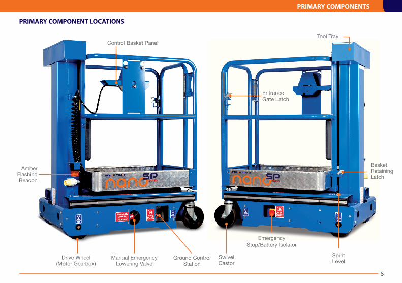
SpiritLevel
SwivelCastor
Drive Wheel(Motor Gearbox)
Emergency Stop/Battery Isolator
Manual Emergency Lowering Valve
Control Basket Panel
Ground ControlStation
Tool Tray
Basket Retaining Latch
Amber Flashing Beacon
EntranceGate Latch

OPERATING PROCEDURES
OPERATING PROCEDURES It is essential to be familiar with the correct operating procedures.
The operator must have adequate training for this type of platform.
The Nano SP Zero requires approved certificated training such as the IPAF 3A category training for self-propelled vertical MEWPS. In addition it is essential that the operator has specific familiarisation handover training for the Nano SP Zero product.
The Nano SP Zero is fitted with a lanyard attachment point as standard. It is recommended that if the operator chooses to wear a safety harness, an approved ‘fall restraint’ type harness should be worn.
Operating procedures are divided into three key areas:
1. Pre-operation checks. What to do before operating the Nano SP Zero.
2. Normal operation. How to use the Nano SP Zero safely.
3. Emergency operation. How to lower the Nano SP Zero without power or in the event of operator incapacity.
6
Mast Wear Screws
Main Control Cable (Curly)
Basket Gas Strut
PowerpackOil Filler Cap Batteries
Battery Charger
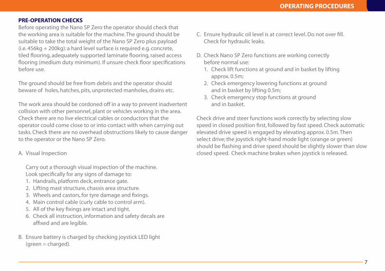
PRE-OPERATION CHECKS Before operating the Nano SP Zero the operator should check that the working area is suitable for the machine. The ground should be suitable to take the total weight of the Nano SP Zero plus payload (i.e. 456kg + 200kg): a hard level surface is required e.g. concrete, tiled flooring, adequately supported laminate flooring, raised access flooring (medium duty minimum). If unsure check floor specifications before use.
The ground should be free from debris and the operator should beware of holes, hatches, pits, unprotected manholes, drains etc.
The work area should be cordoned off in a way to prevent inadvertent collision with other personnel, plant or vehicles working in the area.Check there are no live electrical cables or conductors that the operator could come close to or into contact with when carrying out tasks. Check there are no overhead obstructions likely to cause danger to the operator or the Nano SP Zero.
A. Visual Inspection
Carry out a thorough visual inspection of the machine. Look specifically for any signs of damage to: 1. Handrails, platform deck, entrance gate. 2. Lifting mast structure, chassis area structure. 3. Wheels and castors, for tyre damage and fixings. 4. Main control cable (curly cable to control arm). 5. All of the key fixings are intact and tight. 6. Check all instruction, information and safety decals are affixed and are legible.
B. Ensure battery is charged by checking joystick LED light (green = charged).
C. Ensure hydraulic oil level is at correct level. Do not over fill. Check for hydraulic leaks.
D. Check Nano SP Zero functions are working correctly before normal use: 1. Check lift functions at ground and in basket by lifting approx. 0.5m; 2. Check emergency lowering functions at ground and in basket by lifting 0.5m; 3. Check emergency stop functions at ground and in basket.
Check drive and steer functions work correctly by selecting slow speed in closed position first, followed by fast speed. Check automatic elevated drive speed is engaged by elevating approx. 0.5m. Then select drive; the joystick right-hand mode light (orange or green) should be flashing and drive speed should be slightly slower than slow closed speed. Check machine brakes when joystick is released.
OPERATING PROCEDURES
7

NORMAL OPERATION To operate from the basket:1. Ensure all pre-operation checks have been carried out.2. Check spirit level to ensure machine is level.3. Turn ignition key in ground emergency stop button and release; Power light should illuminate.4. Check ‘Platform’ is selected on ground control panel.5. Enter basket via gate and ensure the gate is closed and latched correctly when in basket.6. The ideal position to operate the Nano SP Zero is to stand facing towards the gate end with your back against the mast.7. Switch on joystick controller by depressing the green on off button – left (see illustration right). 8. Select function by pressing blue mode button (see illustration right). Press and immediately release (0.1 second approximately) to select drive speed right hand LED will illuminate (Green = fast; Orange = slow). Press and hold for approximately 1 second to select lift functions; centre LED light will illuminate (see illustration right).
When drive is selected move joystick forward, backward, left and right as required. Drive speed is infinitely variable depending on how far the joystick is moved. To stop the Nano SP Zero release the joystick. Take particular care when driving in fast speed - quick turns may be awkward to control in confined areas. Always select slow speed when driving in congested/confined areas.
When lift function is selected, move joystick forward (towards gate) to elevate, backwards to descend. Always check for overhead obstructions before elevating. The user shall obtain the guidance and approval of the manufacturer in the event of any special working methods or conditions which are outside those specified by the manufacturer.
EMERGENCY OPERATIONThe Nano SP Zero is fitted with two modes of emergency lowering, one from the basket and one at the ground. NB Always check the area below the platform is free from obstructions before lowering, and that it is safe to do so.
From the basket:In the event of the tilt alarm cut out or overload cut out being activated the basket control joystick will be immobilised and a red light on the basket control panel will flash together with an alarm. To descend, press the black button A on the basket control panel. Releasing the button will stop the descent. In the event of a machine malfunction, breakdown, or accident, the same emergency lowering procedure can be followed.
From the ground:In the event of control failure or operator incapacity the emergency lowering valve located on the chassis (location; right hand side – looking from mast, below fork truck pocket) can be used to manually lower the platform. Simply pull the emergency lowering valve B to lower the platform. Stand clear of the descending structure. Release emergency valve to stop descent.
OPERATING PROCEDURES
8
A
B
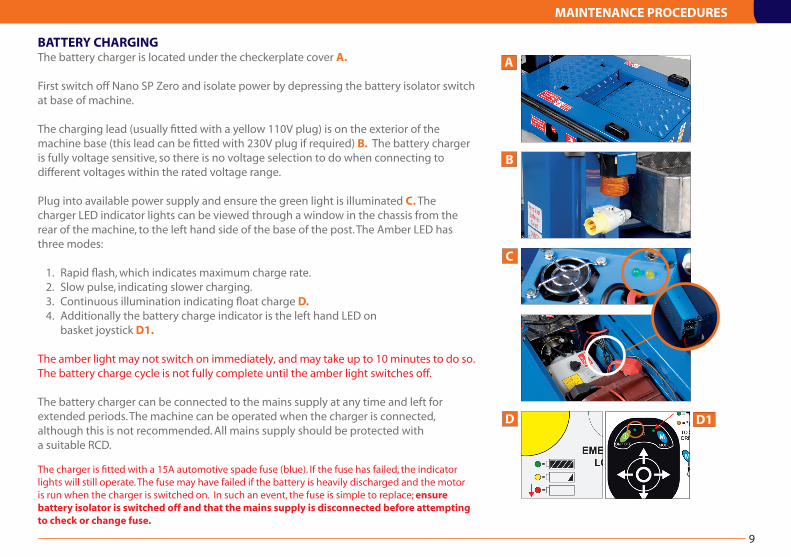
BATTERY CHARGINGThe battery charger is located under the checkerplate cover A.
First switch off Nano SP Zero and isolate power by depressing the battery isolator switch at base of machine.
The charging lead (usually fitted with a yellow 110V plug) is on the exterior of the machine base (this lead can be fitted with 230V plug if required) B. The battery charger is fully voltage sensitive, so there is no voltage selection to do when connecting to different voltages within the rated voltage range.
Plug into available power supply and ensure the green light is illuminated C. The charger LED indicator lights can be viewed through a window in the chassis from the rear of the machine, to the left hand side of the base of the post. The Amber LED has three modes:
1. Rapid flash, which indicates maximum charge rate. 2. Slow pulse, indicating slower charging. 3. Continuous illumination indicating float charge D. 4. Additionally the battery charge indicator is the left hand LED on basket joystick D1. The amber light may not switch on immediately, and may take up to 10 minutes to do so.The battery charge cycle is not fully complete until the amber light switches off.
The battery charger can be connected to the mains supply at any time and left for extended periods. The machine can be operated when the charger is connected, although this is not recommended. All mains supply should be protected witha suitable RCD.
The charger is fitted with a 15A automotive spade fuse (blue). If the fuse has failed, the indicator lights will still operate. The fuse may have failed if the battery is heavily discharged and the motor is run when the charger is switched on. In such an event, the fuse is simple to replace; ensure battery isolator is switched off and that the mains supply is disconnected before attempting to check or change fuse.
MAINTENANCE PROCEDURES
C
A
B
D
9
D1
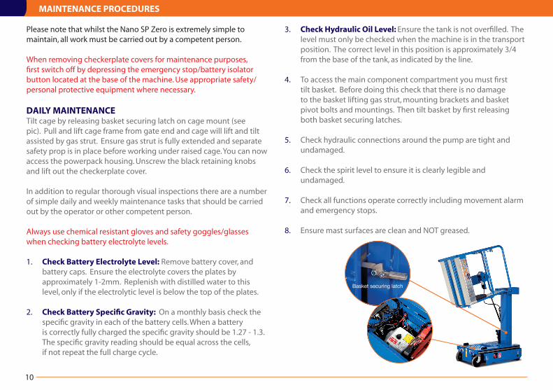
Please note that whilst the Nano SP Zero is extremely simple to maintain, all work must be carried out by a competent person.
When removing checkerplate covers for maintenance purposes, first switch off by depressing the emergency stop/battery isolator button located at the base of the machine. Use appropriate safety/personal protective equipment where necessary.
DAILY MAINTENANCETilt cage by releasing basket securing latch on cage mount (see pic). Pull and lift cage frame from gate end and cage will lift and tilt assisted by gas strut. Ensure gas strut is fully extended and separate safety prop is in place before working under raised cage. You can now access the powerpack housing. Unscrew the black retaining knobs and lift out the checkerplate cover.
In addition to regular thorough visual inspections there are a number of simple daily and weekly maintenance tasks that should be carried out by the operator or other competent person.
Always use chemical resistant gloves and safety goggles/glasses when checking battery electrolyte levels.
1. Check Battery Electrolyte Level: Remove battery cover, and battery caps. Ensure the electrolyte covers the plates by approximately 1-2mm. Replenish with distilled water to this level, only if the electrolytic level is below the top of the plates.
2. Check Battery Specific Gravity: On a monthly basis check the specific gravity in each of the battery cells. When a battery is correctly fully charged the specific gravity should be 1.27 - 1.3. The specific gravity reading should be equal across the cells, if not repeat the full charge cycle.
3. Check Hydraulic Oil Level: Ensure the tank is not overfilled. The level must only be checked when the machine is in the transport position. The correct level in this position is approximately 3/4 from the base of the tank, as indicated by the line.
4. To access the main component compartment you must first tilt basket. Before doing this check that there is no damage to the basket lifting gas strut, mounting brackets and basket pivot bolts and mountings. Then tilt basket by first releasing both basket securing latches.
5. Check hydraulic connections around the pump are tight and undamaged.
6. Check the spirit level to ensure it is clearly legible and undamaged.
7. Check all functions operate correctly including movement alarm and emergency stops.
8. Ensure mast surfaces are clean and NOT greased.
MAINTENANCE PROCEDURES
10
Basket securing latch

MAINTENANCE PROCEDURES
WEEKLY MAINTENANCECheck key fixings are secure: on wheels and castors, cage pivot fixing, basket tray bolts.
Check battery terminal connections are tight.
Check mast rollers and mast surfaces for damage or ingrained debris. Brush off if appropriate. Check brushes brush against mast.
Check main control cable (curly) is not snagged or damaged and is held at each end with a cable clip.
MONTHLY MAINTENANCECheck rollers and mast surfaces for damage. Ensure brushes are fitted correctly and brush against mast surface. Perform battery specific gravity check.
HYDRAULIC OIL The hydraulic oil must be replaced on an annual basis. If the oil is not replaced, premature wear and failure of components will occur.To drain the hydraulic tank, the mast must be in the transport position, and the basket tilted to allow access to the motor/pump unit. The only practical method to remove the oil from the tank is to use a syringe suitable for hydraulic oil, which are easily obtainable, or a vacuum system for hydraulic oil. The hydraulic steel pipe connection to the cylinder must not be disconnected, unless by a competent person. If the connection has been disconnected, then a full pressure test of the system must be conducted prior to placing the machine back into service. No leaks must be evident when the pressure test is conducted.
Refill with grade 32 mineral oil.
WHEELS AND CASTORSIt is absolutely essential that the drive wheels and castors are maintained in good condition at all times, for two reasons:
The first is that they act as the stabilisers, and whilst their load capacity is over rated for the application, any failure could result in a serious accident. Secondly, if the bearings become tight, it will make the machine difficult to manoeuvre.
Check all wheels are free from damage and tyre wear. Check both drive wheels turn freely and are not rubbing on chassis side panel. Check that drive wheel securing clamp is fixed with grub screw. Check drive wheel gearbox fixings are all present and tight. Check castors swivel freely, that both top mounting bolt and axle bolt are secure.
MOTOR CONTACTOR SOLENOIDSPeriodically check that both motor contactor solenoids engage and disengage, either with a continuity meter or a volt meter. The motor contactors must be replaced after every three years of service.
When replacing components for any reason, only use OEM specification parts, either supplied from the manufacturer or authorised in writing by the manufacturer. Warranties and design approvals will be void if alternative components are fitted.It is essential to obtain manufacturer’s approval of any alteration which might affect stability, strength or performance, in writing before proceeding.
11

MAST MAINTENANCEThe mast sections run on maintenance free rollers, and on the outer mast surface where the roller runs, a brush is fitted to keep the mast surface clean, preventing debris picking up in the roller. In addition to these rollers, there are six external plastic screws fitted, which act to hold the mast sections together in torsion. These screws are fitted with M24 lock nuts and can easily be identified at the lower end of the mast sections. Inside the mast there are additional wear pads and rollers, which can be accessed from the top of the mast. These items are not adjustable, and it is very unlikely that any wear will occur.
The mast is raised and lowered with a multistage hydraulic piston, which raises the outer mast section first, followed by the middle mast section. When the mast is lowered, the sections close in the reverse sequence i.e. the middle section and outer section close together until the bottom of the middle section contacts the lower rest buffers, and the outer section continues to close over the middle section. It is essential the mast closes in this sequence.
To ensure the mast sections move in the correct sequence, and do not bind, ensure the wear screws are not over tightened as follows: Ensure the gap between the overlapping mast section and the inner mast
section is even on both sides. The distance is approximately 12mm, but may vary slightly due to manufacturing tolerances.
Loosen the wear screw lock nut and turn the screw until it just contacts the inner mast surface. Do not force the screw. Tighten the locknut using caution not to shear the screw thread. Raise and lower the mast to check it does not bind.
In practice, it is far more likely that the screws may wear so an excessive gap between the mast section and the wear screw develops. This will be evident by free sideways movement of the basket. If this free movement is thought to be excessive, check the gap between the screw and the mast with a feeler gauge. The correct gap should be no more than 0.2mm, although the mast is serviceable with a gap up to 0.5mm.
TILT SWITCH CHECKPre-operation check; elevate platform a small distance and drive machine down or up a gentle slope of around 3 degrees. Machine should stop travelling and alarm sound.
To check the correct operation of the tilt switch raise the platform from the transport position a small distance (e.g.50mm) on truly level ground. Position a suitable lever under one side of the platform and raise this side
of the machine from the ground. The tilt switch should operate when the drive wheel is approximately 25 - 30mm from the ground. This should be repeated from both sides of the machine to compensate for out of level ground...i.e. you might have 20mm one side and 40mm the other side.
When the platform is in the transport position i.e. fully closed, the alarm and cut out should not operate when the above test is repeated. If the cut out and alarm do operate when in the transport position then it is most likely the limit switch is not adjusted correctly or is faulty.
The limit switch and wiring are installed so that should a failure occur, the system will fail to safe mode only i.e. tilt switch operates and cuts out lift when out of level tolerance exceeded.
PLATFORM LOAD SENSING CHECKWith the platform in the retracted position, place 200kgs in the platform. Elevate the platform from the ground controls so the platform floor is approximately 2.0M from the ground. The addition of a small extra load should operate the alarm (there is a small delay from switching to alarm sounding), although the tolerance is up to 40 kgs additional load.
12
MAINTENANCE PROCEDURES
MAINTENANCE FREQUENCY
MAINTENANCE PROCEDURES
13
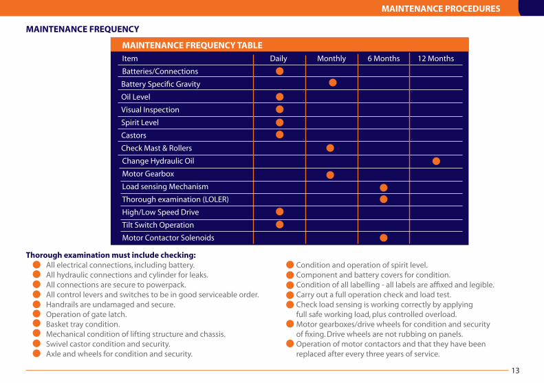
MAINTENANCE FREQUENCY TABLE
Item Daily Monthly 6 Months 12 Months
Batteries/Connections
Battery Specific Gravity
Oil Level
Visual Inspection
Spirit Level
Castors
Check Mast & Rollers
Change Hydraulic Oil
Motor Gearbox
Load sensing Mechanism
Thorough examination (LOLER)
High/Low Speed Drive
Tilt Switch Operation
Motor Contactor Solenoids
Thorough examination must include checking: All electrical connections, including battery. All hydraulic connections and cylinder for leaks. All connections are secure to powerpack. All control levers and switches to be in good serviceable order. Handrails are undamaged and secure. Operation of gate latch. Basket tray condition. Mechanical condition of lifting structure and chassis. Swivel castor condition and security. Axle and wheels for condition and security.
Condition and operation of spirit level. Component and battery covers for condition. Condition of all labelling - all labels are affixed and legible. Carry out a full operation check and load test. Check load sensing is working correctly by applying full safe working load, plus controlled overload. Motor gearboxes/drive wheels for condition and security of fixing. Drive wheels are not rubbing on panels. Operation of motor contactors and that they have been replaced after every three years of service.

14
STORAGEIf the machine is to be taken out of operation for a period longer than one month, the following precautions should be taken.
Ideally, the battery charger should be switched on. The charger has an inbuilt maintenance mode, and will maintain the battery in good condition indefinitely, although obviously the electrolyte level must still be checked periodically. If this is not practical, then the charger should be switched on once a week for half an hour. This is especially important in cold conditions.
The hydraulic oil must be replaced (recommended after 3 months of non-use) as for the procedure in the Maintenance Procedures section.
If the storage period is for an undetermined period, it is advisable that the battery be removed and stored in a secure battery storage container. It is also recommended that all external electrical and hydraulic connections be wax coated to prevent corrosion.
STORAGE OF NANO SP ZERO

15
STORAGE OF Nano SP Zero
ELECTRICAL PARTS
Part No.
A Emergency Stop Button – platform PT-E-003
B Emerg. Stop c/w Key Switch - ground PTNSP-E-614
C Joystick Module PTNSP-E-601
* Black Emergency Lower Button – platform PT-E-007
* LED (Red) – Control Arm PTNSP-E-626
D Coiled cable to basket PTNSP-E-604
E Elevated Drive Speed limit switch PTNSP-E-650
F Tilt Alarm Overide Switch PTNSP-E-649 (actual switch may vary from illustration)
G Load Sensing limit switch PTNSP-E-648
H Tilt Alarm module PTNSP-E-603
I Ground Control Enclosure complete PTNSP-E-606
* Black Push button – ground PT-E-007
* White Push button - ground PT-E-006
J Selector Switch - ground PTNSP-E-643
K Flashing Amber Beacon PTNSP-E-612
L 110v Surface mount plug PTNSP-E-645
KEY SPARE PARTS
A B C
D E F
H I
J K L
G
* Item not shown here
KEY SPARE PARTS
16
Cylinder Solenoid
M N O
P Q R
S T
ELECTRICAL PARTS
Part No.
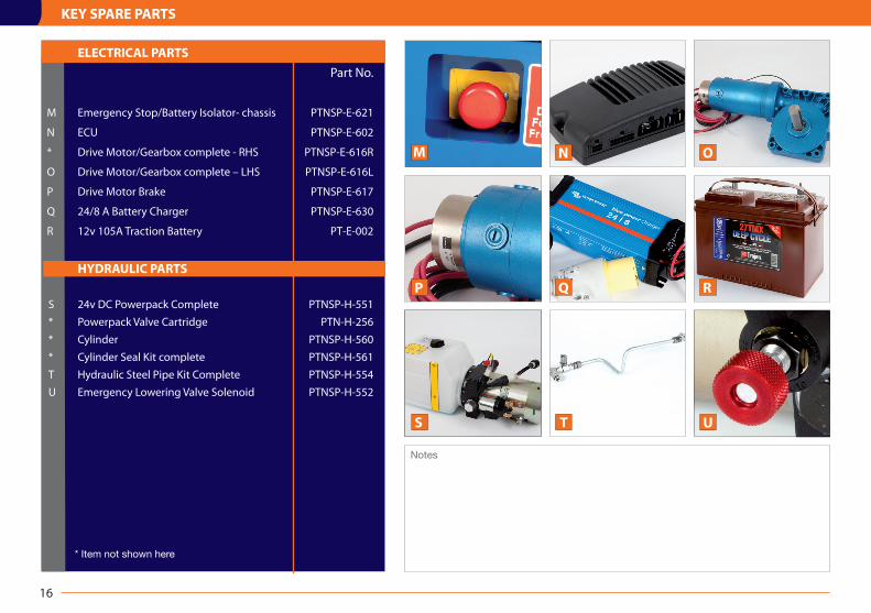
M Emergency Stop/Battery Isolator- chassis PTNSP-E-621
N ECU PTNSP-E-602
* Drive Motor/Gearbox complete - RHS PTNSP-E-616R
O Drive Motor/Gearbox complete – LHS PTNSP-E-616L
P Drive Motor Brake PTNSP-E-617
Q 24/8 A Battery Charger PTNSP-E-630
R 12v 105A Traction Battery PT-E-002
HYDRAULIC PARTS
S 24v DC Powerpack Complete PTNSP-H-551
* Powerpack Valve Cartridge PTN-H-256
* Cylinder PTNSP-H-560
* Cylinder Seal Kit complete PTNSP-H-561
T Hydraulic Steel Pipe Kit Complete PTNSP-H-554
U Emergency Lowering Valve Solenoid PTNSP-H-552
U
* Item not shown here
Notes

MECHANICAL AND MISCELLANEOUS PARTS
Part No.
A Drive Wheel PTNSP-M-500
B H.D. Swivel Castor PTNSP-M-501
C Power-pack Cabinet Cover Plate PTNSP-M-521
D ECU Cover Plate PTNSP-M-522
E Guardrails c/w gate PTNSP0-M-401
F Gate PTNSP0-M-402
G Platform Deck Tray PTNSP0-M-403
A B C
D E F
KEY SPARE PARTS
17
Notes
G
MISCELLANEOUS PARTS
Part No.
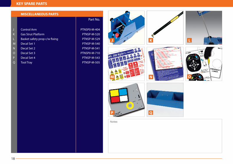
J Control Arm PTNSP0-M-404
K Gas Strut Platform PTNSP-M-520
L Basket safety prop c/w fixing PTNSP-M-529
M Decal Set 1 PTNSP-M-540
N Decal Set 2 PTNSP-M-541
O Decal Set 3 PTNSP0-M-710
P Decal Set 4 PTNSP-M-543
Q Tool Tray PTNSP-M-505
M
KEY SPARE PARTS
O
18
P Q
J K L
Notes
N

19
CIRCUIT DIAGRAM - ELECTRICAL
1 BATTERY ISOLATOR PTNSP-E-6212 80A FUSE PTNSP-E-6153 ALARM RELAY PTNSP-E-6764 DRIVE MOTOR GEAR BOX LEFT OR RIGHT PTNSP-E-616R/L5 ECU PTNSP-E-6026 ELEVATED DRIVE SPEED LIMIT SWITCH PTNSP-E-6507 CONTACT BLOCK NO PT-E-0088 ELEVATION RELAY RY2 PTNSP-E-6769 LOWERING RELAY RY1 PTNSP-E-67610 5A FUSE PT-E-01211 START SOLENOID PTN-H-552
12 POWERPACK LOWERING SOLENOID C/W VALVE PTNSP-H-55213 ALARM PTNSP-E-67514 FLASHING AMBER BEACON PTNSP-E-61215 POWERPACK COMPLETE PTNSP-H-55116 GREEN LED PT-E-02217 LOAD SENSING LIMIT SWITCH PTNSP-E-64818 CONTACT BLOCK NO OR NC NO - PT-E-008 NC - PT-E-00919 GROND SELECTOR CONTACT (PAIR NO & NC) PTNSP-E-62820 CONTACT NC PT-E-00921 EMERGENCY STOP - PLATFORM PT-E-003
22 LED (RED) - CONTROL ARM PTNSP-E-62623 WARNING BLEEPER PTNSP-E-67324 TIMER MODULE PTNSP-E-67425 TILT SWITCH PTNSP-E-60326 TILT SWITCH OVERIDE LIMIT SWITCH PTNSP-E-64927 JOYSTICK MODULE PTNSP-E-60128 COILED CABLE TO BASKET PTNSP-E-60429 HOUR METER (OPTION ONLY) PTNSP-E-67231 LOAD SENSING LIMIT SWITCH (NANO + ONLY) PTNSP-E-64832 DEAD MANS BUTTON - TELEMECHANIQUE ZB2 OR EQUIVAVLENT N.O. CONTACTS
Diagram Key

CIRCUIT DIAGRAM - HYDRAULIC
20
Relief Valve preset to 65 Bar
Single Action2 stage lift cylinder
Manual Bypass
Solenoid Lock Valve
NA-HP-003 Steel Pipe
12V/24V DC Powerpack
WARRANTY TERMS
21
WARRANTYYour Nano SP Zero is covered by an 18 month parts/components warranty (excluding battery and battery charger). The Manufacturer, Power Towers Ltd (The Company) undertakes to replace or repair, free of charge, any defective part/component, which the Company considers to be due to faulty workmanship or material within 18 months of the sale date, except for:
Defects arising from neglect, misuse or unauthorised modifications.
Damage caused by abuse, misuse, dropping or other similar damage caused by or as a result of failure to follow transportation, storage, installation, loading or operation instructions.
Alterations, additions or repairs carried out by persons other than the Manufacturer or their recognised distributors.
Transportation or shipment costs to and from the Manufacturer or their recognised agents, for repair or assessment against a warranty claim, on any Nano SP Zero or component.
Materials and/or labour costs to renew, repair or replace components due to fair wear and tear.
Faults arising from the use of non-standard or additional parts, or any consequential damage or wear caused by the fitting or use of such parts.
ImportantWarranty may at the sole discretion of the manufacturer, be voided if the scheduled service/inspections are not carried out in accordance with this manual.
The Manufacturer and/or their recognised agents, directors, employees or insurers will not be held liable for consequential or other damages, losses or expenses in connection with or by reason of or the inability to use the Nano SP Zero for any purpose.
ModificationsIf additional equipment or any third party work, modifications or alterations are to be carried out on the Nano SP Zero which will involve any welding, drilling or any form of cutting or distortion of materials, full written approval must be obtained from the Manufacturer prior to the work being carried out.

TEST RESULTS & NOTES
Description Work Carried out Date

ALTERATIONS & REPAIRS
Description Work Carried out Date