Operating Instructions TIR-P Infrared Thermometer for Process Applications · Safety Instructions 1...
38
Operating Instructions 42/10-33 EN TIR-P Infrared Thermometer for Process Applications (Sensytherm IR-P)
-
Upload
dinhkhuong -
Category
Documents
-
view
213 -
download
0
Transcript of Operating Instructions TIR-P Infrared Thermometer for Process Applications · Safety Instructions 1...

r a f t Co p y
Operating Instructions42/10-33 EN
TIR-P Infrared Thermometer
for Process Applications(Sensytherm IR-P)
TIR-PInfrared Thermometer for Process Applications(Sensytherm IR-P)
Operating InstructionsDocument No. 42/10-33 EN
Revision 04
Date of issue: 08.04
Manufacturer:ABB Automation Products GmbHBorsigstr. 263755 AlzenauGermany
Tel: +49 551 905-534Fax: +49 551 [email protected]
© Copyright 2004 by ABB Automation Products GmbHSubject to technical changes
This document is protected by copyright. It is a guide to safe and efficient use of the device. It must not be copiednor reproduced in any form whatsoever, neither fully nor in parts, without the prior written permission of the copy-right owner.
TIR-P Infra-red Thermometer for Process Applications 42/10-33 EN

TABLE OF CONTENTS
1 SAFETY INSTRUCTIONS..............................................................................................................................1 2 TECHNICAL DATA.........................................................................................................................................2
2.1 MODELS AND PARAMETERS .........................................................................................................................2 2.2 OPTICAL DIAGRAMS.....................................................................................................................................3 2.3 SCOPE OF DELIVERY .....................................................................................................................................5
3 BASICS ...............................................................................................................................................................6 3.1 MEASUREMENT OF INFRARED TEMPERATURE.............................................................................................6 3.2 DISTANCE AND SPOT SIZE............................................................................................................................6 3.3 AMBIENT TEMPERATURE..............................................................................................................................6 3.4 ATMOSPHERIC QUALITY ..............................................................................................................................7 3.5 ELECTRICAL INTERFERENCE.........................................................................................................................7 3.6 EMISSIVITY OF TARGET OBJECT....................................................................................................................7
4 INSTALLATION ..............................................................................................................................................8 4.1 WIRE PARAMETERS FOR CURRENT LOOP ....................................................................................................8 4.2 DIMENSIONS OF SENSOR ..............................................................................................................................9
4.2.1 Fixed Brackets .......................................................................................................................................9 4.3 CONNECTING THE SIGNAL LINE ..................................................................................................................9 4.4 BASIC MODEL .............................................................................................................................................11
4.4.1 Installation with a Controller..............................................................................................................11 4.5 SMART MODEL ...........................................................................................................................................11
4.5.1 HART Protocol ...................................................................................................................................11 4.5.2 HART RS232 Adapter........................................................................................................................12 4.5.3 Installation of Smart Model ................................................................................................................12 4.5.4 Address Assignment for Multiple Sensors .........................................................................................13 4.5.5 Installation of Multiple Sensors (digital, address mode).....................................................................14 4.5.6 Installation of Multiple Sensors (digital and analog, address mode) ..................................................15 4.5.7 Installation of Multiple Sensors (digital and analog, tag mode) .........................................................15 4.5.8 Alarm Output .....................................................................................................................................16
5 OPTIONS .........................................................................................................................................................17 5.1 AIR/WATER-COOLED HOUSING ................................................................................................................17
5.1.1 Connecting ..........................................................................................................................................18 5.1.2 Avoidance of Condensation .................................................................................................................19
6 ACCESSORIES................................................................................................................................................20 6.1 OVERVIEW ..................................................................................................................................................20 6.2 ADJUSTABLE BRACKET ...............................................................................................................................21 6.3 AIR PURGE COLLAR ...................................................................................................................................21 6.4 RIGHT ANGLE MIRROR ..............................................................................................................................21 6.5 SIGHTING VIEWER ......................................................................................................................................22 6.6 ADJUSTABLE PIPE ADAPTER.......................................................................................................................22 6.7 THERMOJACKET..........................................................................................................................................23 6.8 INDUSTRIAL POWER SUPPLY ......................................................................................................................24 6.9 PROTECTIVE WINDOW ...............................................................................................................................25
42/10-33 EN Infra-red Thermometer for Process Applications

7 MAINTENANCE............................................................................................................................................ 26 7.1 TROUBLESHOOTING MINOR PROBLEMS .................................................................................................... 26 7.2 AUTOMATIC ERROR INDICATION .............................................................................................................. 26 7.3 CLEANING THE LENS ................................................................................................................................. 27 7.4 REPLACING A PROTECTIVE WINDOW........................................................................................................ 27
7.4.1 Models produced after May 1999 ....................................................................................................... 27 7.4.2 Models produced before May 1999 ..................................................................................................... 28
8 APPENDIX....................................................................................................................................................... 29 8.1 DETERMINATION OF EMISSIVITY ............................................................................................................... 29 8.2 TYPICAL EMISSIVITY VALUES .................................................................................................................... 29
INDEX ................................................................................................................................................................ 33
42/10-33 EN Infra-red Thermometer for Process Applications

Safety Instructions
1 Safety Instructions This document contains important information, which should be kept at all times with the instrument during its operational life. Other users of this instrument should be given these instructions with the instrument. Eventual updates to this information must be added to the original document. The instrument can only be operated by trained personnel in accordance with these instructions and local safety regulations.
Acceptable Operation This instrument is intended only for the measurement of temperature. The instrument is appropriate for continuous use. The instrument operates reliably in demanding conditions, such as in high environmental temperatures, as long as the documented technical specifications for all instrument components are adhered to. Compliance with the operating instructions is necessary to ensure the expected results.
Unacceptable Operation The instrument should not be used for medical diagnosis.
Replacement Parts and Accessories Use only original parts and accessories approved by the manufacturer. The use of other products can compromise the operational safety and functionality of the instrument.
Instrument Disposal Disposal of old instruments should be handled according to professional and environmental regulations as electronic waste.
Operating Instructions The following symbols are used to highlight essential safety information in the operation instructions:
Helpful information regarding the optimal use of the instrument.
Warnings concerning operation to avoid instrument damage.
Warnings concerning operation to avoid personal injury.
Pay particular attention to the following safety instructions.
The instrument could be equipped with a Class 2 laser. Class 2 lasers shine only within a visible area at an intensity of 1 mW. Looking directly into the laser beam can produce a slight, temporary blinding effect, but does not result in physical injury or damage to the
eyes, even when the beam is magnified by optical aids. At any rate, closing the eye lids is encouraged when eye contact is made with the laser beam. Pay attention to possible reflections of the laser beam. The laser functions only to locate and mark surface measurement targets. Do not aim the laser at people or animals.
Use in 110 / 230 V electrical systems can result in electrical hazards and personal injury if not properly protected. All instrument parts supplied by electricity must be covered to prevent physical contact and other hazards at all times.
42/10-33 EN Infrared Thermometer for Process Applications 1

Technical Data
2 Technical Data
2.1 Models and Parameters In general, there are two models available. The basic model (TXC, for °C, and TXF, for °F) and the Smart model (TXS). The model descriptor is followed by the description for the optical characteristic, see following page): Optical characteristic LTPSF LTSF MTSF G5SF (Glass) P7SF (Plastics) HTSF Temperature range (°C) - 18 to 500 - 18 to 500 200 to 1000 250 to 1650 10 to 360 500 to 2000 Temperature range (°F) 0 to 1000 0 to 1000 400 to 1800 500 to 3000 50 to 650 950 to 3600 Optical resolution (90%) 15 : 1 33 : 1 33 : 1 33 : 1 33 : 1 60 : 1 Spectral response (µm) 8 to 14 8 to 14 3.9 5.0 7.9 2.2 Close focus CF CF1, CF2 CF1, CF2 CF1, CF2 Thermal Parameters Accuracy ± 1 % of reading or ± 1.4°C (2.5°F), whichever is greater
(at 23°C ± 5°C (73°F ± 9°F) ambient temperature) Repeatability ± 0.5 % of reading or ± 0.7°C, whichever is greater Detector Micromachined Thermopile Response time (95 %) 165 ms (100 ms HT models, 65 ms for G5 models) Temperature resolution (NET) 0.1 K (LT models), 1K (all other models) Emissivity 0.10 to 1.00 (all models) Electrical Parameters Output 4 to 20 mA Maximum loop impedance 750 Ohm Alarm 24 V / 150 mA (only Smart models) Signal processing Smart models °C/°F, Averaging, Peak/Valley Hold, Emissivity, internal housing temperature, external ambient temperature Basic model Emissivity Power 24 VDC ± 10 %, 100 mA, if HART communication is required, otherwise 12 to 24 VDC +20 % General Parameters Environmental rating IP 65, IEC 529, NEMA 4 Ambient operating range without cooling 0 to 70°C (32 to 160°F) with air cooling max. 120°C (250°F) with water cooling max. 175°C (350°F) with ThermoJacket max. 315°C (600°F) Storage temperature - 18°C to 85°C (0 to 185°F) Vibration IEC 68-2-6 (MIL STD 810D), 3 axis, 11 to 200 Hz, 3 G Shock IEC 68-2-27 (MIL STD 810D), 3 axis, 11 ms, 50 G Dimensions / Weight Sensor L: 187 mm; Ø: 42 mm / 330 g (Length 7.36 inches, dia 1.65 inches) with water cooling L: 187 mm; Ø: 60 mm / 595 g (Length 7.36 inches, dia 2.36 inches) Specifications subject to change without notice.
Declaration of Conformity for the European CommunityThis instrument conforms to the following standards: EMC: EN61326-1, Safety: EN61010-1:1993 / A2:1995
2 Infrared Thermometer for Process Applications 42/10-33 EN

Technical Data
2.2 Optical Diagrams The optical diagrams indicate the target spot diameter at any given distance between the target object and the sensing head. All target spot sizes indicated in the optical diagrams are based on 90% energy.
Figure 1: How to read the optical diagrams
Target Spot Diameter(S) and Measuring
Distance (D) in CloseFocus in inches
Target Spot Diameter S (in)
Distance D (in)
Target Spot Diameter(S) and Measuring
Distance (D) in CloseFocus in mm
Target Spot Diameter S (mm)
Distance D (mm)
Distance between Sensor and Object [in]
Distance between Sensor and Object [mm]
Close Focus D : S = Proportion between Distance (D) to Target Spot and Target Spot Diameter (S) in Close Focus
Far Field D : S = Proportion with Distances 10 times greater than theClose Focus Distance
Calculating the Target Spot Size To calculate the target spot size from two known points within an optical diagram the following formula can be used:
( )( ) ( )
−⋅
−−
+= nfnf
nxnx SS
DDDDSS
Sx = unknown diameter of target spot Sn = smallest known diameter of target spot Sf = greatest known diameter of target spot Dx = distance to unknown target spot Dn = distance to smaller known target spot Df = distance to greater known target spot
42/10-33 EN Infrared Thermometer for Process Applications 3

Technical Data
Plastic Lens, Standard Focus SF
Plastic Lens, Close Focus CF
Low and Medium Temperature Ranges, G5 (Glass), P7 (Plastic), Standard Focus SF
Low and Medium Temperature Ranges, High Resolution, Close Focus CF1
Low and Medium Temperature Ranges, High Resolution, Close Focus CF2
High Temperature, Standard Focus SF
High Temperature, Close Focus CF1
High Temperature, Close Focus CF2
Figure 2: Optical Diagrams
LTCF2, MTCF2
LTSF, MTSF, G5SF, P7SF
LTPSF LTPCF
LTCF1, MTCF1
HTSF
HTCF2 HTCF1
* Focus Point D:S = 15:1 Far Field D:S = 14:1
Distance D Sensor to Object [in]
Distance D Sensor to Object [mm]
Spot
Dia.
[mm]
Spot
Dia.
[in]
* Focus Point D:S = 7:1 Far Field D:S = 4:1
Distance D Sensor to Object [in]
Distance D Sensor to Object [mm]
Spot
Dia.
[mm]
Spot
Dia.
[in]
* Focus Point D:S = 33:1 Far Field D:S = 30:1
Distance D Sensor to Object [in]
Distance D Sensor to Object [mm]
Spot
Dia.
[mm]
Spot
Dia.
[in]
* Focus Point D:S = 30:1 Far Field D:S = 5:1
Distance D Sensor to Object [in]
Distance D Sensor to Object [mm]
Spot
Dia.
[mm]
Spot
Dia.
[in]
* Focus Point D:S = 32:1 Far Field D:S = 10:1
Distance D Sensor to Object [in]
Distance D Sensor to Object [mm]
Spot
Dia.
[mm]
Spot
Dia.
[in]
* Focus Point D:S = 60:1 Far Field D:S = 42:1
Distance D Sensor to Object [in]
Distance D Sensor to Object [mm]
Spot
Dia.
[mm]
Spot
Dia.
[in]
* Focus Point D:S = 60:1 Far Field D:S = 7:1
Distance D Sensor to Object [in]
Distance D Sensor to Object [mm]
Spot
Dia.
[mm]
Spot
Dia.
[in]
* Focus Point D:S = 60:1 Far Field D:S = 14:1
Distance D Sensor to Object [in]
Distance D Sensor to Object [mm]
Spot
Dia.
[mm]
Spot
Dia.
[in]
4 Infrared Thermometer for Process Applications 42/10-33 EN

Technical Data
2.3 Scope of Delivery All models are provided with:
• operator´s manual • a fixed bracket • mounting nut • model have 4 to 20 mA output.
42/10-33 EN Infrared Thermometer for Process Applications 5

Basics
3 Basics
3.1 Measurement of Infrared Temperature Everything emits an amount of infrared radiation according to its surface temperature. The intensity of the infrared radiation changes according to the temperature of the object. Depending on the material and surface properties, the emitted radiation lies in a wavelength spectrum of approximately 1 to 20 µm. The intensity of the infrared radiation (”heat radiation”) is dependent on the material. For many substances this material-dependent constant is known. It is referred to as ”emissivity value”, see appendix 8.2 Typical Emissivity Values on page 29. Infrared thermometers are optical-electronic sensors. These sensors are able to detect ”radiation of heat”. Infrared thermometers are made up of a lens, a spectral filter, a sensor, and an electronic signal processing unit. The task of the spectral filter is to select the wavelength spectrum of interest. The sensor converts the infrared radiation into an electrical parameter. The connected electronics generate electrical signals for further analysis. As the intensity of the emitted infrared radiation is dependent on the material, the required emissivity can be selected on the sensor. The biggest advantage of the infrared thermometer is its ability to measure in the absence of contact. Consequently, surface temperatures of moving or hard to reach objects can easily be measured.
3.2 Distance and Spot Size The desired spot size on the target will determine the maximum measurement distance and the necessary focus length of the optical module. To avoid erroneous readings the target spot size must contain the entire field of view of the sensor. Consequently, the sensor must be positioned so the field of view is the same as or smaller than the desired target size. For a list indicating the available focus models and their parameters see Figure 2: Optical Diagrams on page 4.
Figure 3: Proper Sensor Placement
3.3 Ambient Temperature The sensing head is designed for measurements in ambient temperatures between 0°C and 70°C (32 to 160°F). In ambient conditions above 70°C (160°F), a water or air cooled housing is available to extend the operating range to 120°C (250°F) with air cooling and to 175°C (350°F) with water cooling. When using the water cooled housing, it is strongly recommended to use the supplied air purge collar to
Target greater than spot size
Target greater equal to spot sizeTarget smaller than spot size
Best Good Incorrect
Background
6 Infrared Thermometer for Process Applications 42/10-33 EN
Basics
avoid condensation on the lens. In ambient conditions up to 315°C (600°F), the ThermoJacket housing should be used.
3.4 Atmospheric Quality In order to prevent damage to the lens and erroneous readings, the lens should always be protected from dust, smoke, fumes, and other contaminants. For this purpose an air purge collar is available. You should only use oil free, clean “instrument“ air.
3.5 Electrical Interference To minimize electrical or electromagnetic interference, follow these precautions:
• Mount the sensor as far away as possible from possible sources of interference such as motorized equipment producing large step load changes.
• Ensure a fully insulated installation of the sensor (Avoid ground loops!). • Make sure the shield wire in the sensor cable is earth grounded at one location.
3.6 Emissivity of Target Object Determine the emissivity of the target object as described in appendix 8.1 Determination of Emissivity on page 29. If emissivity is low, measured results could be falsified by interfering infrared radiation from background objects (such as heating systems, flames, fireclay bricks, etc. close beside or behind the target object). This type of problem can occur when measuring reflecting surfaces and very thin materials such as plastic films and glass. This measuring error when measuring objects with low emissivity can be reduced to a minimum if particular care is taken during installation, and the sensing head is shielded from these reflecting radiation sources.
42/10-33 EN Infrared Thermometer for Process Applications 7

Installation
4 Installation The infrared sensor provides a standard two-wire current loop output and has been designed for use in harsh industrial environments. The Smart model allows the remote programming of the temperature range, alarm values and other functions.
4.1 Wire Parameters for Current Loop You should use shielded twisted pairs or multiple twisted pairs with a joint shield. Line length The maximum line length of one two-wire line per loop is dependent on the loop resistance (R), the capacitance per length unit (C), and the capacitance of the sensor CS (5000 pF). It is calculated as follows:
C10000C
CR1065l S
6 +−
⋅⋅
≈
For simplifying the formula use, the parameters must be provided as “naked values” (in the given dimension)! Typical values for wire cross sections (copper)
• up to 250 m line length: 0.2 mm2 cross section AWG24 • up to 650 m line length: 0.5 mm2 cross section AWG20 • up to 1500 m multiple wire line lengths: 1.5 mm2 cross section • up to 3000 m single wire line lengths: 2.5 mm2 cross section
l … in meter R … in Ohm C … in pF / m CS … in pF
8 Infrared Thermometer for Process Applications 42/10-33 EN

Installation
4.2 Dimensions of Sensor All sensors are supplied with a fixed bracket and mounting nut. Alternatively, the sensor may also be mounted using customer-supplied accessories. A pipe adapter and other accessories may also be used (see section 6.1 Overview on page 20.
All sensors and accessories are supplied with 1.5“ 20 UN 2 threads.
Figure 4: Dimensions of the Sensor
4.2.1 Fixed Brackets
Figure 5: Dimensions (left), sensor delivered with fixed bracket XXXTXXACFB (right)
4.3 Connecting the Signal Line Before connecting the cable to the sensor (standard and Smart models) you should unscrew the cap from the back of the sensor. Proceed as follows:
Protective Window
42/10-33 EN Infrared Thermometer for Process Applications 9

Installation
1.) Prepare the cable, remove about 6cm (2.36 in) of the insulation. Shorten the shield to about 1cm (0.4 in). Tin-
coat the connecting leads.
2.) Unscrew the end-cap until it can be pulled away from the sensor body.
3.) Open the PG threaded cable gland.
4.) The cable gland consists of a PG nut, a plastics part and a metal cone ring.
5.) Feed the prepared cable through the components of
the cable gland.
6.) Make sure to have a proper contact between the braided shield and the metal cone ring.
7.) Place the PG screwed cable gland back into the
outer cap. Tighten the PG nut firmly.
8.) Connect the signal wires to the screw terminals.
9.) Screw the end-cap firmly onto the sensor until it is tight (flush with the sensor body).
IMPORTANT: Neither the end-cap nor the cable gland should have any play after tightening.
The screwed cable gland described above is not a strain relief! Consequently, the cable must be clamped accordingly during the installation. The outside diameter of the connecting cables (round cable) should lie between 4 to 6 mm (about 0.2 inches). Note that it might be necessary to additionally seal the cable entry to allow IP65 with smaller cables.
10 Infrared Thermometer for Process Applications 42/10-33 EN

Installation
4.4 Basic Model The standard model is available for °C or °F. It provides a 2 pin screw-jumper terminal for connecting the 4 to 20 mA current loop. The polarity is indicated on the panel. Above the screw-jumper terminal there are two rotary switches for emissivity setting. Emissivity is preset at the factory at 0.95 (see figure). The appendix lists typical emissivity values for common materials, see appendix 8.2 Typical Emissivity Values on page 29.
4.4.1 Installation with a Controller
Figure 7: Typical installation of basic model
4.5 Smart Model The Smart model has a 3 pin screw-jumper terminal for connecting the 4 to 20 mA current loop and the alarm output. The terminal assignment is marked on the panel. To allow clip leads from a HART adapter to attach directly to the sensor for setting sensor parameters, raise the removable terminal strip about 4 mm (0.2 inches) from the rear panel board and connect across the exposed (+) and (-) pins. For example, via line terminals, a lap-top with a HART adapter can be used for programming the sensor.
4.5.1 HART Protocol Originally, transmission of information was in one direction only, from sensing head to process control. The parameters monitored for the production of a product were not changed. In order to use the same technological equipment to manufacture a multitude of differing products, it must be possible to quickly alter many process parameters. This has an effect on the sensing head. Measuring range, accuracy and alarm values must be redefined. It would be extremely inconvenient if it were necessary to reprogram the sensing head at the unit every time. The HART protocol arose from this requirement. It allows the application of ”intelligent” sensors. The sensing heads can be programmed from the control room. This means that information is transmitted in two directions. The sensing head provides analog measured values to the control room via the 4 to 20 mA current loop. The sensing head can be reprogrammed from the control room by means of bi-directional transmission of digital
Figure 8: Back panel of basic model
Figure 6: Back panel of basic model
Controller
Shield Basic model
42/10-33 EN Infrared Thermometer for Process Applications 11

Installation
signals. The superposition of analog and digital signals is described by the HART protocol. Sensors which are programmable in this way are called SMART sensors. Apart from the Smart model, a HART(RS232) adapter is also available. This adapter allows programming of infrared sensing heads using a computer with an RS232 interface.
4.5.2 HART RS232 Adapter The adapter (XXXTXACRCK) allows both remote setting and signal processing of one or more sensors in a 4 to 20 mA current loop. A software suitable for a WINDOWS PC are supplied together with the adapter. The adapter has a 25-pin terminal connector for connecting to an RS232 interface. Screw terminals are provided for connecting the 4 to 20 mA current loop, terminal 4 (S2) and terminal 5 (S1).
Terminal 6 is connected internally to computer chassis ground.
4.5.3 Installation of Smart Model
Figure 10: Typical installation of Smart model using the external resistor
Figure 11: Typical installation of Smart model using the internal resistor
Figure 9: HART RS232 adapter
Controller, Display, or just nothing within the current loop. Computer
COM-Port
Controller, Display, or just nothing within the current loop.
Computer COM-Port
12 Infrared Thermometer for Process Applications 42/10-33 EN
Installation
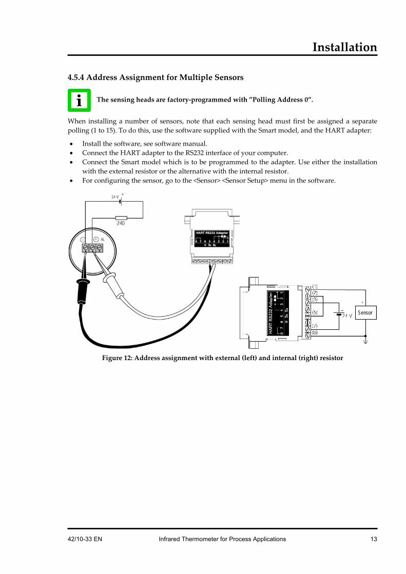
4.5.4 Address Assignment for Multiple Sensors
The sensing heads are factory-programmed with ”Polling Address 0”.
When installing a number of sensors, note that each sensing head must first be assigned a separate polling (1 to 15). To do this, use the software supplied with the Smart model, and the HART adapter:
• Install the software, see software manual. • Connect the HART adapter to the RS232 interface of your computer. • Connect the Smart model which is to be programmed to the adapter. Use either the installation
with the external resistor or the alternative with the internal resistor. • For configuring the sensor, go to the <Sensor> <Sensor Setup> menu in the software.
Figure 12: Address assignment with external (left) and internal (right) resistor
Sensor
42/10-33 EN Infrared Thermometer for Process Applications 13

Installation
4.5.5 Installation of Multiple Sensors (digital, address mode) • Maximum 15 sensors can be used. The polling address must always be >0. • Communication is purely digital, no analog current output is provided • Set each sensor failsafe mode to “minimum”
Figure 13: All sensors in digital communication using the external resistor
Figure 14: Multiple sensors using the internal resistor
The sensing heads are factory-programmed with ”Polling Address 0”.
When installing a number of sensors, note that each sensing head must first be assigned a separate polling address (1 to 15), section 4.5.4 Address Assignment for Multiple Sensors on page 13).
POWER SUPPLY Sensors Voltage [V] Op. Current [mA]
1 2 3 4 5 6 7 8 9 10 11 12
13 14 15
24 24 24 24 24 24 24 24 24 24 24 24
28 28 28
4 8 12 16 20 24 28 32 36 40 44 48
52 56 60
HART/RS232 Adapter
Monitor
Shield (6)
Sensor1 Sensor2 Sensor...
!
14 Infrared Thermometer for Process Applications 42/10-33 EN

Installation
4.5.6 Installation of Multiple Sensors (digital and analog, address mode) • Maximum 12 sensors can be used. • Analog and digital communication for the sensor with polling address 0. • Communication for the remaining 11 sensors purely digital.
Figure 15: All sensors in digital communication, first sensor also with analog current output
The sensing heads are factory-programmed with ”Polling Address 0”.
When installing a number of sensors, note that each sensing head must first be assigned a separate polling address (0 to 11), section 4.5.4 Address Assignment for Multiple Sensors on page 13).
4.5.7 Installation of Multiple Sensors (digital and analog, tag mode) To run a sensor with analog current output, the sensor is to address with polling address 0. In case of having multiple sensors running with analog current output, the polling address can not be the criteria to distinguish between the sensors, because every sensor would be set to the same address. To avoid this, a sensor can be named by means of a so called tag. The tag will be stored within the units memory and can later be used to identify the sensor uniquely.
POWER SUPPLY Sensors Voltage [V] Op. Current [mA]
1 2 3 4 5 6 7 8
9 10 11 12
24 24 24 24 24 24 24 24
28 28 28 28
23 27 31 35 39 43 47 51
55 59 63 67
HART/RS232 Adapter
Monitor
Shield (6)
!
42/10-33 EN Infrared Thermometer for Process Applications 15

Installation
Figure 16: All sensors in digital communication and with analog current output
In case of having more than 3 units, please contact your local dealer for additional information for installing.
To prepare sensors for tag mode: 1. The sensing heads are factory-programmed with ”Polling Address 0”. 2. Start up the software with a single sensor (address mode). 3. Define a unique tag for the sensor, see the <Advanced Setup> in the menu <Sensor> <Sensor
Setup>. 4. Exit the software. 5. Repeat steps 2 to 4 for every additional sensor. 6. Start up the software with multiple sensors, select <Define Scan List>, input the tags for all
requested sensors.
4.5.8 Alarm Output The alarm output of the Smart model is not electrically isolated. The maximum current carrying capacity is 150 mA. Use the circuit diagram. The LED is operated with 10 mA and could be used as an indicator, or as an optocoupler. The alarm current does not influence the signal current (4 to 20 mA current loop).
Figure 17: Using the alarm output
HART/RS232 Adapter
Monitor
Shield (6)
current loop
curre
nt du
ring a
larm
16 Infrared Thermometer for Process Applications 42/10-33 EN

Options
5 Options A full range of options for various applications and environments are available. Options are factory-installed and must be specified at the time of placing the order:
• °C or °F (basic model only) • Air/Water cooled housing (Option: …W), includes air purge • Intrinsically-safe rating, PTB-approval (Smart models only) (Option: …IS) • ISO Calibration Certificate (XXXTXCERT) based on PTB certified transfer pyrometers
5.1 Air/Water-Cooled Housing The Air/Water-Cooled Housing option allows the sensor to be used in ambient temperatures up to 120°C (250°F) with air-cooling, and 175°C (350°F) with water-cooling. The cooling media should be connected using 1/8” NPT stainless steel fittings. Air flow should be 1.4 to 2.5 l/sec at 25°C (77°F). Water flow should be approximately 1.0 to 2.0 l/min (water temperature between 10 and 27°C (50 to 80.6°F). Chilled water below 10°C (50°F) is not recommended, see section 5.1.2 Avoidance of Condensation on page 19.
Figure 18: Sensor with Air/Water-Cooled Housing
Stainless Steel Fittings
42/10-33 EN Infrared Thermometer for Process Applications 17

Options
5.1.1 Connecting EUROPEAN CUSTOMERS: This information is especially important to European customers concerning the use of NPT and metric threads.
As a standard the accessory parts are supplied with stainless steel fittings and non-metric 1/8” NPT threads. If you intend to supply the cooling media through pipes or hoses, we recommend using the following additional accessories. For any further information on material, range of types offered, terms of delivery and payment, please directly contact the manufacturer:
B.E.S.T. Ventil- und Fitting GmbH München Max-Anderl-Straße 2 85375 Neufahrn bei Freising Tel.: (08165) 95 28 -0 Fax: (08165) 95 28 10
The following adapters and supplementary parts shall serve as an example only and are taken from the manufacturer’s delivery program at the time of printing this manual. Prior to any order, you should therefore inquire at B.E.S.T. Ventil- und Fitting GmbH about the current order numbers. • Thread Adapter - metric pipe to NPT inside thread • Thread Adapter - inch-type pipe to NPT inside thread
• Supporting tube for PVC or Tygon hoses
Ordering Example: Inner Thread NPT (in.) Pipe Outer Ø Order number:
1/8 4 mm SS – 4M0-7-2 1/8 6 mm SS – 6M0-7-2 1/8 8 mm SS – 8M0-7-2
Inner Thread NPT (in.) DIN-ISO-Outer Thread Order number: 1/8 4 mm SS – 2-A-2RS
Related sealing ring: S – 4 – RS.2B (only DIN-ISO Outer Threads)
Ordering Example:
Tube Outer Ø Tube Inner Ø Order number: 6 4 SS – 6M5-4M
8 6 SS – 8M5-6M
18 Infrared Thermometer for Process Applications 42/10-33 EN

Options
5.1.2 Avoidance of Condensation If environmental condition makes water cooling necessary, it is strictly recommended to check whether condensation will be a real problem or not. Water cooling also causes a cooling of the air in the inner part of the device. Thereby the capability of the air to store water decreases. The relative humidity increases and can reach 100% very quickly. In case of a further cooling, the surplus water steam will come out as water (condensation). The water will condense on the lenses and the electronics resulting in possible damage to the sensor. Condensation can even happen on an IP65 sealed housing.
There is no warranty repair possible in case of condensed water within the housing!
To avoid condensation, the temperature of the cooling media and the flow rate have to ensure a minimum device temperature. The minimum device temperature depends on the ambient temperature and the relative humidity, please consider the following table.
Relative Humidity [%] 10 15 20 25 30 35 40 45 50 55 60 65 70 75 80 85 90 95 100
0/ 32
0/ 32
0/32
0/ 32
0/ 32
0/ 32
0/32
0/32
0/32
0/32
0/32
0/32
0/32
0/32
0/ 32
0/ 32
0/ 32
0/32
0/32
0/32
5/ 41
0/ 32
0/32
0/ 32
0/ 32
0/ 32
0/32
0/32
0/32
0/32
0/32
0/32
0/32
0/32
0/ 32
0/ 32
0/ 32
0/32
0/32
5/41
10/ 50
0/ 32
0/32
0/ 32
0/ 32
0/ 32
0/32
0/32
0/32
0/32
0/32
0/32
0/32
0/32
5/ 41
5/ 41
5/ 41
5/41
5/41
10/50
15/ 59
0/ 32
0/32
0/ 32
0/ 32
0/ 32
0/32
0/32
0/32
0/32
5/41
5/41
5/41
5/41
10/ 50
10/ 50
10/ 50
10/50
10/50
15/59
20/ 68
0/ 32
0/32
0/ 32
0/ 32
0/ 32
0/32
5/41
5/41
5/41
10/50
10/50
10/50
10/50
15/ 59
15/ 59
15/ 59
15/59
15/59
20/68
25/ 77
0/ 32
0/32
0/ 32
0/ 32
5/ 41
5/41
10/50
10/50
10/50
10/50
15/59
15/59
15/59
20/ 68
20/ 68
20/ 68
20/68
20/68
25/77
30/ 86
0/ 32
0/32
0/ 32
5/ 41
5/ 41
10/50
10/50
15/59
15/59
15/59
20/68
20/68
20/68
20/ 68
25/ 77
25/ 77
25/77
25/77
30/86
35/ 95
0/ 32
0/32
5/ 41
10/ 50
10/ 50
15/59
15/59
20/68
20/68
20/68
25/77
25/77
25/77
25/ 77
30/ 86
30/ 86
30/86
30/86
35/95
40/ 104
0/ 32
5/41
10/ 50
10/ 50
15/ 59
20/68
20/68
20/68
25/77
25/77
25/77
30/86
30/86
30/ 86
35/ 95
35/ 95
35/95
35/95
40/104
45/ 113
0/ 32
10/50
15/ 59
15/ 59
20/ 68
25/77
25/77
25/77
30/86
30/86
35/95
35/95
35/95
35/ 95
40/ 104
40/ 104
40/104
40/104
45/113
50/ 122
5/ 41
10/50
15/ 59
20/ 68
25/ 77
25/77
30/86
30/86
35/95
35/95
35/95
40/104
40/104
40/ 104
45/ 113
45/ 113
45/113
45/113
50/122
60/ 140
15/ 59
20/68
25/ 77
30/ 86
30/ 86
35/95
40/104
40/104
40/104
45/113
45/113
50/122
50/122
50/ 122
50/ 122
50/ 122
50/122
50/122
60/140
70/ 158
20/ 68
25/77
35/ 95
35/ 95
40/ 104
45/113
45/113
50/122
50/122
50/122
50/122
50/122
60/140
60/ 140
60/ 140
60/ 140
60/140
60/140
70/158
80/ 176
25/ 77
35/95
40/ 104
45/ 113
50/ 122
50/122
50/122
60/140
60/140
60/140
60/140
60/140
70/158
70/ 158
70/ 158
70/ 158
70/158
70/158
80/176
90/ 194
35/ 95
40/104
50/ 122
50/ 122
50/ 122
60/140
60/140
60/140
70/158
70/158
70/158
70/158
80/176
80/ 176
80/ 176
80/ 176
80/176
80/176
90/194
Am
bien
t Tem
pera
ture
[°C
/°F]
100/ 212
40/ 104
50/122
50/ 122
60/ 140
60/ 140
70/158
70/158
70/158
80/176
80/176
80/176
80/176
80/176
90/ 194
90/ 194
90/ 194
90/194
90/194
100/212
Tab. 1: Minimum device temperatures [°C/°F]
Temperatures higher than 60°C / 140°F are not recommended due to the temperature limitation of the device.
Example: Ambient temperature = 50 °C Relative humidity = 40 % Minimum device temperature = 30 °C
The use of lower temperatures is at your own risk!
42/10-33 EN Infrared Thermometer for Process Applications 19

Accessories
6 Accessories
6.1 Overview For all models:
• Mounting Nut XXXTXXACMN • Fixed Mounting Bracket XXXTXXACFB • Adjustable Bracket XXXTXXACAB • Air Purge Collar XXXTXXACAP • Right Angle Mirror XXXTXXACRA • Sighting Viewer XXXTXXACSV • Adjustable Pipe Adapter XXXTXXAPA • ThermoJacket Housing RAYTXXTJ3M • Industrial Power Supply (110 / 230 VAC – 24 VDC) XXXTXACDCPS • Protective Window for lens protection • Panel Mount Display RAYGPC/RAYGPCM
For Smart model: • PC communications software, RS232 adapter XXXTXACRCK • Field Calibration Kit incl. XXXTXACRCK RAYTXSCAL
Figure 19: Overview to the available accessories
Adjustable Pipe Adapter (XXXTXXAPA)
Sighting Viewer (XXXTXXACSV)
Right Angle Mirror (XXXTXXACSV)
Air Purge Collar (XXXTXXACAP)
Mounting Nut (XXXTXXACMN)
Sensor
Fixed Bracket (XXXTXXACFB)
Adjustable Bracket (XXXTXXACAB)
Sensor with Air-/Water Cooled Housing (Option)
ThermoJacket and Accessories (RAYTXXTJ3M)
20 Infrared Thermometer for Process Applications 42/10-33 EN
Accessories
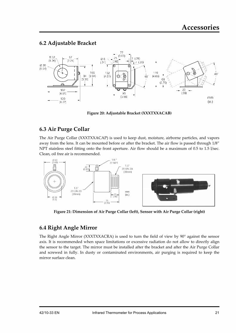
6.2 Adjustable Bracket
Figure 20: Adjustable Bracket (XXXTXXACAB)
6.3 Air Purge Collar The Air Purge Collar (XXXTXXACAP) is used to keep dust, moisture, airborne particles, and vapors away from the lens. It can be mounted before or after the bracket. The air flow is passed through 1/8” NPT stainless steel fitting onto the front aperture. Air flow should be a maximum of 0.5 to 1.5 l/sec. Clean, oil free air is recommended.
Figure 21: Dimension of Air Purge Collar (left), Sensor with Air Purge Collar (right)
6.4 Right Angle Mirror The Right Angle Mirror (XXXTXXACRA) is used to turn the field of view by 90° against the sensor axis. It is recommended when space limitations or excessive radiation do not allow to directly align the sensor to the target. The mirror must be installed after the bracket and after the Air Purge Collar and screwed in fully. In dusty or contaminated environments, air purging is required to keep the mirror surface clean.
42/10-33 EN Infrared Thermometer for Process Applications 21

Accessories
Figure 22: Right Angle Mirror
When using the Right Angle Mirror, adjust the emissivity settings downward by 5%. For example, for an object with an emissivity of 0.65, you adjust the value down to 0.62. This correction accounts for energy losses in the mirror.
6.5 Sighting Viewer The Sighting Viewer (XXXTXXACSV) is used to aid in the alignment of the standard sensor. It is used when the object is small and far from the sensor as well as when it is difficult to obtain a direct in-line sighting. It can be used both with and without the Air Purge Collar, but not with the Right Angle Mirror. First secure the sensor to the bracket using the mounting nut or the Air Purge Collar. Next screw on the Sighting Viewer Tool fully. Now, position and secure the bracket. When the alignment is complete, do not forget to remove the Sighting Viewer Tool. The Sighting Viewer Tool has the same dimensions as the Right Angle Mirror.
6.6 Adjustable Pipe Adapter The adjustable pipe adapter (XXXTXXACPA) is available to connect a sighting tube or conduit to a sensor with or without water/air cooled housing.
Figure 23: Adjustable Pipe Adapter
22 Infrared Thermometer for Process Applications 42/10-33 EN

Accessories
6.7 ThermoJacket The ThermoJacket® allows use of the sensor in ambient temperatures up to 315°C (600°F). The rugged cast aluminum housing completely encloses the sensor and provides water cooling as well as air purging. Sensing heads can easily be installed or removed with the ThermoJacket housing in its mounted position.
Figure 24: ThermoJacket (RAYTXXTJ3)
For more information see the ThermoJacket’s manual.
42/10-33 EN Infrared Thermometer for Process Applications 23

Accessories
6.8 Industrial Power Supply The industrial power supply (type S-25-24) transforms an input voltage of 100 – 240 VAC into an output voltage of 24 VDC / 1.1 A. Do not twist the mounting screws deeper than 2 mm (0.08 in.) into the mounting threads.
To prevent electrical shocks, the power supply must be used in protected environments (cabinets)!
Figure 25: Dimension of Industrial Power Supply
DC Output –V DC Output +V FG AC Input L AC Input N
24 Infrared Thermometer for Process Applications 42/10-33 EN

Accessories
6.9 Protective Window Protective windows can be used to protect the sensor’s optic against dust and other contaminations. For sensors with plastic lenses the use of a protective window combined with the air purge is strongly recommended. The following table provides an overview of the available protective windows recommended for a LT, MT, HT, G5 and P7 model. All protective windows have a transmission below 100%.
Order number Model Designation Material Transmissivity Use
XXXTXACTWL LT none Amtir 0.65 ±0.05 max. 300°C (572°F)
XXXTXACTWX LT 1 red dot Zinc Sulphid 0.75 ±0.05 max. 250°C (482°F) non-poisonous
XXXTXACTWLF1 LT none (stainless steel) Polyethylene foil 0.75 ±0.05 for food applications, non-poisonous, non-fragile
XXXTXACTWM MT 4 red dots Sapphire 0.88 ±0.05 max. 1800°C (3272°F)
XXXTXACTWH HT 3 red dots Glass 0.88 ±0.05 max. 900°C (1652°F)
XXXTXACTWGP G5, P7 2 red dots Calcium Fluorid 0.93 ±0.05 max. 600°C (1112°F)
Tab. 2: Protective Windows
For special requirements, please ask our Sales Department about our range of special protective windows.
Models delivered with mounted protective windows are preset as follows:
Basic model Basic model has no adjustable parameter for the transmissivity. The influence of transmissivity is reflected by a resulting emissivity value. E.g. transmissivity of protective window is 0.88, emissivity of measured object is 0.95, resulting emissivity value is set with the two rotary switches to 0.84 (0.88 * 0.95 = 0.84)
Smart model Transmissivity for the protective window is set in the software directly. The emissivity value is not changed.
Determination of transmissivity of an unknown protective window: If transmissivity of the measuring screen is not indicated on the data sheet, you can also determine the transmissivity yourself. Please proceed as follows:
1. Measure the temperature of the target object with the sensing head, without using the protective window. Note correct setting of emissivity. With the basic model, emissivity is set with the two rotary switches. For the Smart model, the emissivity is entered in the software and the value for “Transmissivity“ is specified as 1.00.
2. Insert the protective window in the sensing head. 3. If you use the basic model of the sensing head, adjust the emissivity until the same temperature
is displayed, as was determined without the protective window. If the smart model is used, adjust the transmissivity in the software until the same temperature is displayed, as it was determined without the protective window.
For more information regarding the mounting of a protective window, see section 7.4 Replacing a Protective Window on page 27.
42/10-33 EN Infrared Thermometer for Process Applications 25

Maintenance
7 Maintenance Our customer service representatives are always at your disposal for any questions you might have. This service includes any support regarding the proper application of your infrared measuring system, calibration or the solution to customer-specific solutions as well as repair. In many cases your problems will be applications-specific and can possibly be solved over the telephone. So, if you need to return equipment to us, please contact our Service Department before doing so, see phone and fax numbers at the beginning of this document.
7.1 Troubleshooting Minor Problems
Symptom Possible Cause Solution
No Output
Erroneous Temperature
Erroneous Temperature
Erroneous Temperature
Erroneous Temperature
Temperature Fluctuates
Cable Disconnected
Faulty Sensor Cable
Field of View Obstructed
Lens Dirty
Wrong Emissivity Setting
Wrong Signal Processing
Check Cable Connections
Verify Cable's Integrity
Remove the Obstruction
Clean the Lens
Correct the Setting
Correct Peak, Valley, or Average Settings
Tab. 3: Troubleshooting
7.2 Automatic Error Indication The automatic error indication (alarm output) shall warn the user and guarantee a secure output in the event of a system error. In the first place, however, its task is to switch the system off in case of a faulty setup or a defect in the sensing head or in the electronic circuits. Please select the desired Alarm Mode, see <Advanced Setup> in the menu <Sensor> <Sensor Setup> of the software.
• Off no alarm function • Normally Open open output within the alarm thresholds • Normally Closed closed output within the alarm thresholds • Intern. Temp. n.c. open, if internal sensor temperature is exceeded • Intern. Temp. n.o. closed if internal sensor temperature is exceeded
Never rely exclusively on the automatic error indication when monitoring critical heating processes. It is strongly recommended to take additional safety measures.
26 Infrared Thermometer for Process Applications 42/10-33 EN

Maintenance
7.3 Cleaning the Lens Care should be taken to keep the lens clean. Any foreign matter on the lens will affect the accuracy of the measurements. Be sure to take care when cleaning the lens. Please observe the following:
1. Blow off lose particles with clean air. 2. Gently brush off remaining particles with a soft camel hair brush. 3. To remove any more severe contamination use a clean, soft cloth dampened with distilled
water. In any case, do not scratch the lens surface!
For finger prints or other grease, use any of the following: • Denaturated alcohol • Ethanol • Kodak lens cleaner
Apply any of the above to the lens. Wipe gently with a clean, soft cloth until you see colors on the lens surface, then allow to air dry. Never wipe the surface dry, this may scratch the surface. If the lens is contaminated with silicones (e.g. from hand creams), clean it carefully using Hexane. Allow the lens to air dry.
Do not use any ammonia or any cleaners containing ammonia to clean the lens. This may result in permanent damage to the lens’ surface.
7.4 Replacing a Protective Window
7.4.1 Models produced after May 1999 Attention! Beginning production date May 1999, the models contain a thread allowing an easier protective window exchange. (If you received your model together with this manual, your model was produced after May 1999.) If you own an older model, refer to the description given in section 7.4.2 Models produced before May 1999 on page 28.
Make sure to use the appropriate protective window for the spectral range of your sensor model, for more information see section 6.9 Protective Window on page 25.
The window material is placed in a metal ring with a thread with an inner rubber gasket. This rubber gasket hermetically seals the sensor against atmospheric contaminants. Replace the protective window using the special tool supplied with the spare window. Put the tools nozzles into the wholes on the window’s mounting ring. Now gently unscrew the protective window from its mount by turning to the left. Take care to screw in the new protective window as tight as possible, but do not over tighten!
42/10-33 EN Infrared Thermometer for Process Applications 27

Maintenance
Figure 26: Replacing the Protective Window
7.4.2 Models produced before May 1999 Attention! If you own a model produced before May 1999 and where the protective window looks similar to the one shown on the photographs below, refer to the following description.
Make sure to use the appropriate protective window for the spectral range of your sensor model, for more information see section 6.9 Protective Window on page 25.
The window material is placed in a metal ring which is enclosed with a rubber gasket. This rubber gasket keeps the protective window in the sensor. (Models produced later than May 1999 have a thread instead - check this, before you order spare parts!) Replace the protective window using the plastic levers supplied with the spare window. Place the levers’ blades beneath the projection of the protective window. Now gently lever the protective window from its mount.
Figure 27: Replacing the Protective Window
Sensor Window
Mounting Tool
28 Infrared Thermometer for Process Applications 42/10-33 EN

Appendix
8 Appendix
8.1 Determination of Emissivity Emissivity is a measure of an object’s ability to absorb and emit infrared energy. It can have a value between 0 and 1.0. For example a mirror has an emissivity of 0.1, while the so-called “Blackbody“ reaches an emissivity value of 1.0. If a higher than actual emissivity value is set, the output will read low, provided the target temperature is above its ambient temperature. For example, if you have set 0.95 and the actual emissivity is 0.9, the temperature reading will be lower than the true temperature. An object’s emissivity can be determined by one of the following methods:
1. Determine the actual temperature of the material using an RTD (PT100), a thermocouple, or any other suitable method. Next, measure the object’s temperature and adjust emissivity setting until the correct temperature value is reached. This is the correct emissivity for the measured material.
2. For relatively low temperatures (up to 260°C, 500°F) place a plastic sticker on the object to be measured. This sticker should be large enough to cover the target spot. Next, measure the sticker’s temperature using an emissivity setting of 0.95. Finally, measure the temperature of an adjacent area on the object and adjust the emissivity setting until the same temperature is reached. This is the correct emissivity for the measured material.
3. If possible, apply flat black paint to a portion of the surface of the object. The emissivity of the paint must be above 0.98. Next, measure the temperature of the painted area using an emissivity setting of 0.98. Finally, measure the temperature of an adjacent area on the object and adjust the emissivity until the same temperature is reached. This is the correct emissivity for the measured material.
8.2 Typical Emissivity Values The following table provides a brief reference guide for determining emissivity and can be used when one of the above methods is not practical. Emissivity values shown in the table are only approximate, since several parameters may affect the emissivity of a material. These include the following:
1. Temperature 2. Angle of measurement 3. Geometry (plane, concave, convex) 4. Thickness 5. Surface quality (polished, rough, oxidized, sandblasted) 6. Spectral range of measurement 7. Transmissivity (e.g. thin films plastics)
42/10-33 EN Infrared Thermometer for Process Applications 29
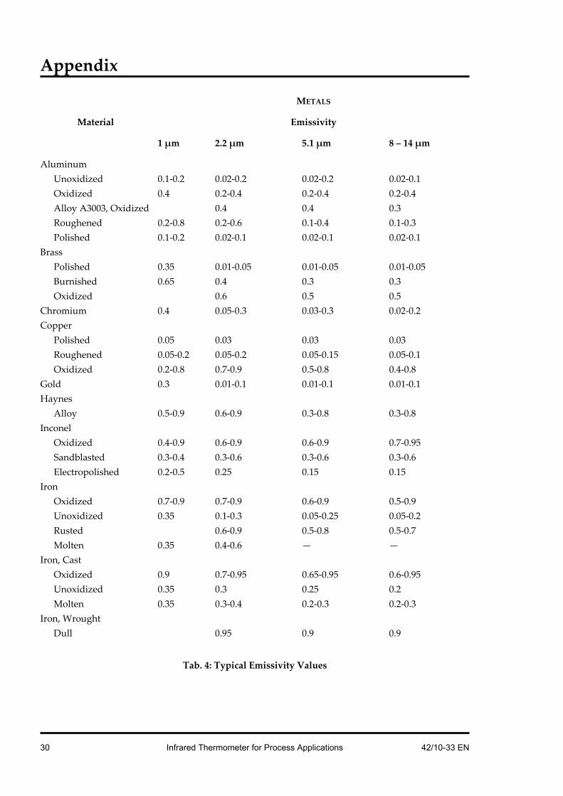
Appendix
METALS
Material Emissivity
1 µm 2.2 µm 5.1 µm 8 – 14 µm
Aluminum Unoxidized 0.1-0.2 0.02-0.2 0.02-0.2 0.02-0.1 Oxidized 0.4 0.2-0.4 0.2-0.4 0.2-0.4 Alloy A3003, Oxidized 0.4 0.4 0.3 Roughened 0.2-0.8 0.2-0.6 0.1-0.4 0.1-0.3 Polished 0.1-0.2 0.02-0.1 0.02-0.1 0.02-0.1
Brass Polished 0.35 0.01-0.05 0.01-0.05 0.01-0.05 Burnished 0.65 0.4 0.3 0.3 Oxidized 0.6 0.5 0.5
Chromium 0.4 0.05-0.3 0.03-0.3 0.02-0.2 Copper
Polished 0.05 0.03 0.03 0.03 Roughened 0.05-0.2 0.05-0.2 0.05-0.15 0.05-0.1 Oxidized 0.2-0.8 0.7-0.9 0.5-0.8 0.4-0.8
Gold 0.3 0.01-0.1 0.01-0.1 0.01-0.1 Haynes
Alloy 0.5-0.9 0.6-0.9 0.3-0.8 0.3-0.8 Inconel
Oxidized 0.4-0.9 0.6-0.9 0.6-0.9 0.7-0.95 Sandblasted 0.3-0.4 0.3-0.6 0.3-0.6 0.3-0.6 Electropolished 0.2-0.5 0.25 0.15 0.15
Iron Oxidized 0.7-0.9 0.7-0.9 0.6-0.9 0.5-0.9 Unoxidized 0.35 0.1-0.3 0.05-0.25 0.05-0.2 Rusted 0.6-0.9 0.5-0.8 0.5-0.7 Molten 0.35 0.4-0.6 — —
Iron, Cast Oxidized 0.9 0.7-0.95 0.65-0.95 0.6-0.95 Unoxidized 0.35 0.3 0.25 0.2 Molten 0.35 0.3-0.4 0.2-0.3 0.2-0.3
Iron, Wrought Dull 0.95 0.9 0.9
Tab. 4: Typical Emissivity Values
30 Infrared Thermometer for Process Applications 42/10-33 EN

Appendix
METALS
Material Emissivity
1 µm 2.2 µm 5.1 µm 8 – 14 µm
Lead Polished 0.05-0.2 0.05-0.2 0.05-0.1 Rough 0.5 0.4 0.4 Oxidized 0.3-0.7 0.2-0.7 0.2-0.6
Magnesium 0.3-0.8 0.05-0.2 0.03-0.15 0.02-0.1 Mercury 0.05-0.15 0.05-0.15 0.05-0.15 Molybdenum
Oxidized 0.5-0.9 0.4-0.9 0.3-0.7 0.2-0.6 Unoxidized 0.25-0.35 0.1-0.3 0.1-0.15 0.1
Monel (Ni-Cu) 0.3 0.2-0.6 0.1-0.5 0.1-0.14 Nickel
Oxidized 0.8-0.9 0.4-0.7 0.3-0.6 0.2-0.5 Electrolytic 0.2-0.4 0.1-0.2 0.1-0.15 0.05-0.15
Platinum Black 0.95 0.9 0.9
Silver 0.04 0.02 0.02 0.02 Steel
Cold-Rolled 0.8-0.9 — 0.8-0.9 0.7-0.9 Ground Sheet 0.6-0.7 0.5-0.7 0.4-0.6 Polished Sheet 0.35 0.2 0.1 0.1 Molten 0.35 0.25-0.4 0.1-0.2 — Oxidized 0.8-0.9 0.8-0.9 0.7-0.9 0.7-0.9 Stainless 0.35 0.2-0.9 0.15-0.8 0.1-0.8
Tin (Unoxidized) 0.25 0.1-0.3 0.05 0.05 Titanium
Polished 0.5-0.75 0.2-0.5 0.1-0.3 0.05-0.2 Oxidized 0.6-0.8 0.5-0.7 0.5-0.6
Tungsten 0.1-0.6 0.05-0.5 0.03 Polished 0.1-0.3 0.05-0.25 0.03-0.1
Zinc Oxidized 0.6 0.15 0.1 0.1 Polished 0.5 0.05 0.03 0.02
Tab. 5: Typical Emissivity Values
42/10-33 EN Infrared Thermometer for Process Applications 31

Appendix
NON-METALS
Material Emissivity
1 µm 2.2 µm 5.1 µm 8 – 14 µm
Asbestos 0.9 0.8 0.9 0.95 Asphalt — 0.95 0.95 Basalt — 0.7 0.7 Carbon
Unoxidized 0.8-0.9 0.8-0.9 0.8-0.9 Graphite 0.8-0.9 0.7-0.9 0.7-0.8
Carborundum 0.95 0.9 0.9 Ceramic 0.4 0.8-0.95 0.8-0.95 0.95 Clay 0.8-0.95 0.85-0.95 0.95 Concrete 0.65 0.9 0.9 0.95 Cloth — 0.95 0.95 Glass
Plate 0.2 0.98 0.85 “Gob” 0.4-0.9 0.9 —
Gravel — 0.95 0.95 Gypsum — 0.4-0.97 0.8-0.95 Ice — — 0.98 Limestone — 0.4-0.98 0.98 Paint (non-al.) — — 0.9-0.95 Paper (any color) — 0.95 0.95 Plastic (opaque, over 20 mils) — 0.95 0.95 Rubber — 0.9 0.95 Sand — 0.9 0.9 Snow — — 0.9 Soil — — 0.9-0.98 Water — — 0.93 Wood, Natural — 0.9-0.95 0.9-0.95
Tab. 6: Typical Emissivity Values
To optimize surface temperature measurements, consider the following guidelines: • Determine the object emissivity using the instrument which is also to be used for the
measurements. • Avoid reflections by shielding the object from surrounding temperature sources. • For higher temperature objects use instruments with the shortest wavelength possible. • For translucent materials such as plastic foils or glass, assure that the background is uniform
and lower in temperature than the object.
32 Infrared Thermometer for Process Applications 42/10-33 EN

Index
Accessories.....................................................................................................................................................17, 20 Address ....................................................................................................................................................14, 15, 16 Address Assignment ..............................................................................................................................13, 14, 15 Address Mode .........................................................................................................................................14, 15, 16 Air Cooling ........................................................................................................................................................2, 6 Air Purge Collar ............................................................................................................................................21, 22 Alarm Mode.........................................................................................................................................................26 Alarm Output ..........................................................................................................................................11, 16, 26 Ambient Temperature..................................................................................................................6, 17, 19, 23, 33 Bracket, fixed .....................................................................................................................................................5, 9 Condensation.......................................................................................................................................................19 Emissivity.............................................................................................................................6, 7, 11, 22, 25, 29, 32 Focus...................................................................................................................................................................2, 6 HART Adapter ..............................................................................................................................................11, 13 Industrial Power Supply....................................................................................................................................24 Intrinsic Safety.....................................................................................................................................................34 Lens ........................................................................................................................................................4, 20, 26, 27 Maintenance ........................................................................................................................................................26 Optical Diagrams ..................................................................................................................................................3 Pipe Adapter..................................................................................................................................................20, 22 Polling Address.................................................................................................................................13, 14, 15, 16 Resistor, external...........................................................................................................................................12, 14 Resistor, internal ...........................................................................................................................................12, 14 Right Angle Mirror .................................................................................................................................20, 21, 22 Sighting Viewer.............................................................................................................................................20, 22 Spot Size .............................................................................................................................................................3, 6 Tag Mode .......................................................................................................................................................15, 16 ThermoJacket Housing...............................................................................................................................2, 7, 23 Thread Adapter...................................................................................................................................................18 Transmissivity ...............................................................................................................................................25, 29 Water Cooling .............................................................................................................................................2, 6, 23 Wire Cross Sections ..............................................................................................................................................8
42/10-33 EN Infrared Thermometer for Process Applications 33

42/1
0-33
EN
Rev
. 04
ABB Ltd.Salterbeck Trading EstateWorkington, Cumbria, CA14 5DSUKTel: +44(0)1946-830-611Fax: +44(0)1946-832-661
ABB Automation Products GmbHBorsigstr. 263755 AlzenauGermanyTel: +49 551 905-534Fax: +49 551 [email protected]
ABB Inc.125 E. County Line RoadWarminster, PA 18974USATel: +1 215-674-6000Fax: +1 215-674-7183
The IndustrialIT wordmark and all mentioned product names in the form XXXXXXIT are registered or pending trademarks of ABB.
ABB has Sales & Customer Supportexpertise in over 100 countries worldwide.
www.abb.com
The Company’s policy is one of continuous productimprovement and the right is reserved to modify the
information contained herein without notice.
Printed in the Fed. Rep. of Germany (08.04)
© ABB 2004