Operating Instructions Status as of 08/2012 P-CHARGE EWS-Box
28
P - CHARGE EWS-Box Controller for electric charging stations Operating Instructions Status as of 08/2012
Transcript of Operating Instructions Status as of 08/2012 P-CHARGE EWS-Box

P-CHARGE EWS-BoxController for electric charging stations
Operating Instructions Status as of 08/2012

2
P-CHARGE EWS-BoxController for electric charging stations
1. Introduction 3
2 Hardware 32.1 Setup 32.1.1 Mechanical 32.1.2 Electronic 32.2 Management 42.2.1 Process 42.2.2 Locking 52.2.3 Power-Backup (EWS-Box P) 62.3 Return notifi cations 62.3.1 System 62.3.2 Users 72.4 Communication 82.4.1 Features 82.4.2 PC Confi guration 82.4.3 Ethernet 82.4.4 RFID 9
3. Software 93.1 Functionality description 93.1.1 Standalone 103.1.2 Server connection 113.1.3 RFID-Integration 123.2 Communication with the module 123.2.1 RS232-Settings 123.2.2 Data protocol / Server connection per API 123.2.3 Info data set 133.2.4 Command reference 133.2.4.1 Firmware update 203.3 RFID-Card structure 20
4 Installation guidelines 204.1 Integration into a system 204.2 Mains terminals 214.2.1 Power supply terminals 214.2.2 Contactor terminals 214.3 Communication – Interfaces 224.3.1 Introduction 224.3.2 Ethernet 224.3.3 PC – Confi guration 224.3.4 RFID - Reader 234.4 Confi guration switch 234.5 User-interface 244.6 12V - Supply 274.7 Power backup 27
Operating Instructions Status as of 08/2012

3
3.1 Preface
The communication module was designed and is deployed as the main control unit for an electric vehicle charging station. It can serve as a Wallbox on a private site or, equally, in a fully equipped charging pillar in a commer-cial environment. The primary function of the EWS-Box is to ensure that the charging process is eff ected as per user request once an appropriate connec-tion between electric vehicle and charging station has been detected.The module performs all control and notifi cation functions required for the connection of an electric vehicle to a cable-bound charging device and complies with IEC 61851, Mode 3. In order to meet increased demand, particularly in the commercial environment, the communication module is capable of monitoring and controlling two connected users simultaneously but independently of each other.A module can be aligned to environmentally-specifi c parameters to be run as a self-suffi cient operation, or can be integrated into a wider network of systems. For this purpose, both charging outlets can be monitored and managed via telecontrol systems, facilitated by the integrated communica-tion options and hosted by one main instance. The module is of compact design and is particularly suited to application with standardized bearing rail combinations (top-hat rail mounting).
2 Hardware2.1 Structure
2.1.1 MechanicalThe module is contained within a plastic housing and is deployed in assem-bly outfi ts in accordance with DIN EN 60715. This enables integration into systems which host components arranged in sequence. The retaining clips are integrated into the underside of the housing, ensuring secure adherence to the mounting rails.Once the module is secure on the rails, all connections can be accessed from above and below. Alignment of the module can be arbitrary and is dependent solely upon the location of the power-supply lines. The running of supply lines to and from the module must be eff ected in accordance with the connection diagram and with the installation instructions.The housing cover can be easily removed and replaced for maintenance purposes. The snap-on housing has a securely lockable cover. In order to install the power backup circuit board, the cover can be released from the locking device and tilted upwards. It is not necessary to remove the snap-on housing for this purpose..
2.1.2 electricalThe communication module is connected to the mains power supply. In a three-phase circuit, L1 is run to the module. The mains connection serves only to supply the module and for activation of the AC contactor and the ventilation mechanism (L1 is interconnected), not for the supply of power to the user or to any other system components.
Operating Instructions Status as of 08/2012

4
The electric vehicle has the capacity to signal to the charging system a need for ventilation (e.g. for gassing batteries). If a ventilation system has been pre-configured by the user, it is activated by the communication module. If this is not the case, then authorization to charge the respective vehicle is not granted. The user is responsible for ensuring that the ventilation system is compliant with all vehicle manufacturers and with all legal regulations. One universal ventilation system is activated for both users as it is assumed that the two vehicles are charged in close proximity to each other.The module has an internal residual current device (6.3A/fuse) which serves solely to protect the communication system. In addition to the main fuse, installation of an RCD switch is also recommended for protection of the entire system. Cables and safety components to be connected to the module are not delivered as integral components of the communication system and must therefore comply, separately, with legal requirements for electrical safety. The user is obligated to compare the data sheets for the deployed components with the communication module data and to conciliate these..
2.2 ManageMent
2.2.1 WorkfloWA powerful 16bit microprocessor is active within the communications box. This ensures a fast response to a variety of potential environmental factors by pro-cessing system-generated instructions effectively and without long wait times.Basic management of the system can be carried out by the communication module itself. Initiation of the charging process is a 3-phase process:
1. Connection of a charging cable is detected. 2. A response from the proximity circuit (PP) confirms the connected cable
and correlates it with the charging capability of the system. If compatible, (the maximum current carrying capability of the cable must correspond to that of the system), communication is initiated with the electric vehicle.
3. With the aid of the pilot function (CP) of the connection cable, the com-munication module determines the presence of the electric vehicle and validates the necessity for activation of a ventilation system (for gassing batteries). Should ventilation be necessary, this is duly activated for the entire system, irrespective of whether or not it is required for the second user.
If all conditions are fulfilled and the user has initiated the charging process by pressing the START button (locally or remotely), the charging outlet is locked, the charging contactor is activated and the charging process started. The charging process is monitored by a higher level, intelligent control system.
PleaSe note: The box does not provide this intelligence. It does not recognize the energy requirement of the connected unit, nor can it align the charging process to the current conditions. During the course of the charg-ing process, it simply conveys to the electric vehicle the volume of energy currently available by the system, if this information is known. If the system cannot communicate the actual quantity of energy available to the module, then the communication module pre-supposes that the quantity of available energy complies with the maximum configured for the module.
Operating Instructions Status as of 08/2012
PE
N
L
CP+PP
Schematic overview diagram (only one user depicted)
Charging socket IEC 62196-2Main supply with fuse protection and RCDCharging contactor ManagementPower Communication moduleSystem (local or remote management)
5
Possible settings can be configured in advance via the jumper, with the follow-ing limits:
1. 13A2. 20A3. 32A4. 63A (3-PH)/70A (1-PH)
These values simply convey the capacity of the communication module to scale the connected cable to the available system resources. The system manufacturer is responsible for aligning the module values with those of the system. Please refer to the installation guide for possible jumper configuration options. A configured value can be further limited by a system parameter but not exceeded. If a module has an integrated cable, then this value also applies to the cable as there is no resistance detection.
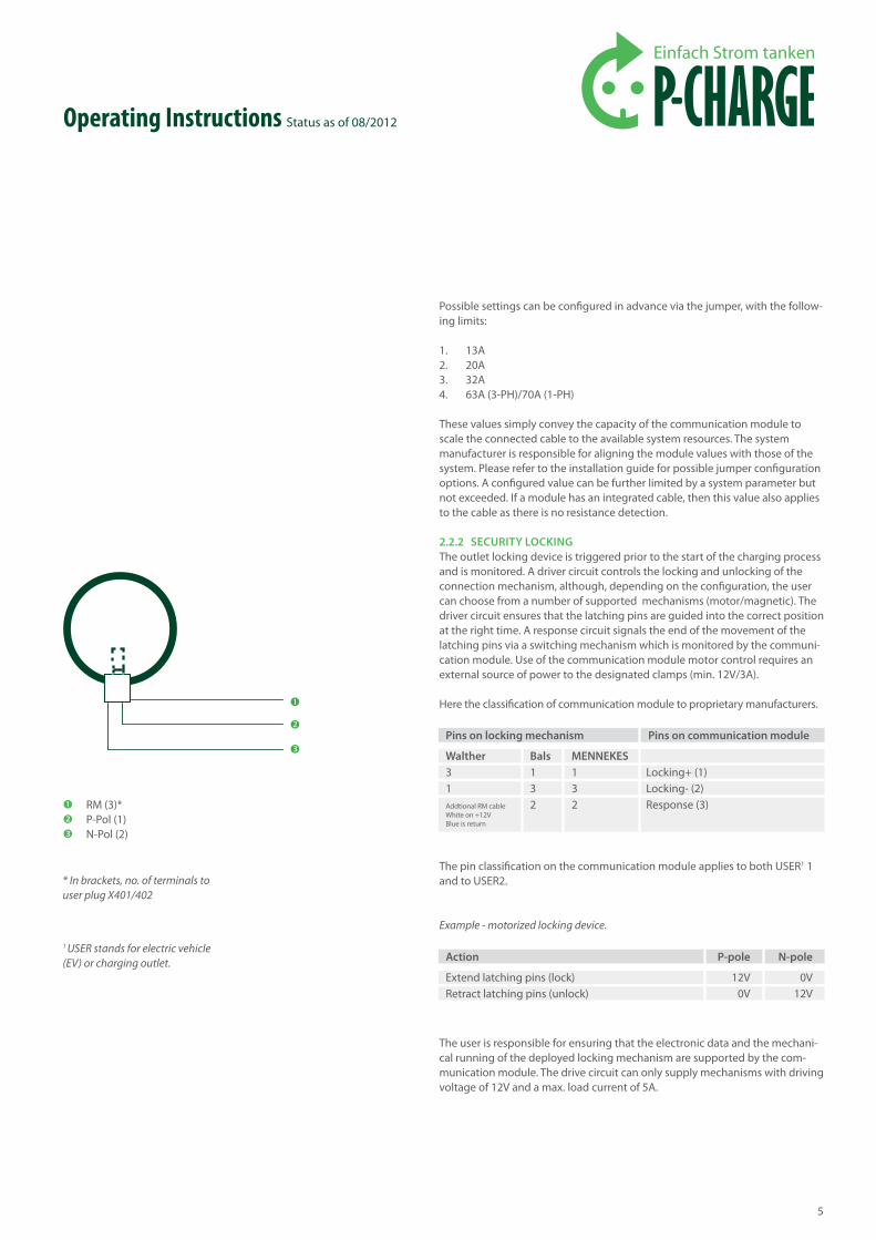
2.2.2 Security lockingThe outlet locking device is triggered prior to the start of the charging process and is monitored. A driver circuit controls the locking and unlocking of the connection mechanism, although, depending on the configuration, the user can choose from a number of supported mechanisms (motor/magnetic). The driver circuit ensures that the latching pins are guided into the correct position at the right time. A response circuit signals the end of the movement of the latching pins via a switching mechanism which is monitored by the communi-cation module. Use of the communication module motor control requires an external source of power to the designated clamps (min. 12V/3A).
Here the classification of communication module to proprietary manufacturers.
The pin classification on the communication module applies to both USER1 1 and to USER2.
Example - motorized locking device.
The user is responsible for ensuring that the electronic data and the mechani-cal running of the deployed locking mechanism are supported by the com-munication module. The drive circuit can only supply mechanisms with driving voltage of 12V and a max. load current of 5A.
Operating Instructions Status as of 08/2012
* In brackets, no. of terminals to user plug X401/402
1 USER stands for electric vehicle (EV) or charging outlet.
RM (3)*P-Pol (1)N-Pol (2)
Pins on locking mechanism
Walther31Addtional RM cable White on +12V Blue is return
Bals132
MennekeS132
Pins on communication module
Locking+ (1)Locking- (2)Response (3)
action
Extend latching pins (lock)Retract latching pins (unlock)
P-pole
12V0V
n-pole
0V12V

6
The communications box monitors the availability of mains power and switch-es the mechanism to "unlock" in the event of a power outage. Prerequisite is that the external 12V power supply delivers energy to the amount of min. 200ms (determined from the hold up time) for the communication module (which is also supplied by external voltage in the event of network outage).
2.2.3 PoWer-BackuP (eWS-Box P)With variant EWS Box P, the user can deploy the Power Backup function. This solution integrates the generation of required energy to the locking mechanism switch within the module. A special circuit saves all non-required energy in the dormant periods in order to feed the locking mechanism later if required. The power backup provides the required energy for unlocking the charging outlet in the event of a network outage. The additional circuit board is pre-installed in the P variant - the communication module autonomously detects the use of the Power Backup function and engages itself accordingly. The module continuously checks the energy status until sufficient power is available to supply the locking / unlocking devices.
attention: This results in an extended response-time. Once activated, it will take up to 260 seconds for sufficient energy to be saved. If several switching operations are triggered, one after another, then then a few seconds may be needed until sufficient energy is available for the next operation.
2.3 feedBack SignalS
2.3.1 SySteMThe connected system can provide current information via a series of feedback terminals within the communication module. A separate series of terminals is available for each user.
Includes:• Feedback contactor - the system registers the correct switching of the
power-supply contactor. As long as the auxiliary contact is active, power can be supplied to the electric vehicle and the locking mechanism can not be opened.
• RCD feedback - the system registers the release of the RCD switch and with it an interruption to the supply of power.
• Meter input signal - Energy metering impulses generated by a meter during the course of the current charging process are transmitted to the communication module by the system (via the usual S+ S- mechanism). The user must stipulate (in the configuration settings) in which resolution the impulse values are to be read (e.g. 1000 impulses/kWh). These values can be taken from the data sheets for the active meter. It is assumed that there is a voltage impulse of 0 +12V 0 at the S- input constitutes a counting pulse of between 30 ms and 200 ms. Prerequisite: the S+ input was connected at +12V). Shorter impulses are disregarded, longer impulses interpreted as errors.
• Feedback locking mechanism - The system advises of the latching / unlatch-ing of the mechanism via a switch in the locking device (generally connec-tion 2). With this feedback signal, the module acknowledges a correctly locked charging socket and can authorize the start of a charging session.
Operating Instructions Status as of 08/2012

7
2.3.2 uSerSTwo different information options are available to each user
1. 4 x LEDs
– LED1 – Error, the module has detected a fault situation. A root cause analysis must be performed on any fault which hinders the running of a charging process.The problem must be corrected for the process to continue uninterrupted. Here are a few examples of possible errors:
• the connected cable is not compatible with the energy capacity of the module.
• the locking mechanism could not be could not be closed in the required position.
• the RCD switch was not released
If the fault cannot be localized, the current status must be read. More informa-tion can be found in the software manual.
– LED2 – On / Ready, this LED-output signalizes 3 states:
• OFF – no (recognizable) cable connected at the outlet and no Start command triggered
• FLASHING – either the system is searching for a vehicle at the connected cable, or, if a vehicle is present, the system is awaiting a START command.
• ON – a START command was received and the charging process has been initiated
– LED3 – optimized charging, the user has requested a customized charg-ing process for this connection, i.e. the charging session is controlled by (externally set) parameters, e.g. The use of cost-efficient off-peak power, time-apportioned fleet management. More information can be found in the software manual.
– LED4 - no classification. The LEDs, (together with the meter input S-) share a supply line (+12V - max. 40 mA) that is to be used exclusively to this purpose.
2 4 x buttons
– Button 1 – Start, the user can initiate a charging process via this button. LED2 blinks to indicate that the request has been acknowledged. Once all prerequisites are fulfilled (correct cable connected, electric vehicle shows ready, no error messages) then the locking device is activated and the charging process started. The user can query the current status (e.g. energy meter) locally or remotely.
– Button2 –Stop, a currently running charging process is ended. The supply of power is deactivated and the locking device opened.
– Button3 – optimized charging, the user commissions a customized charg-ing process. This means that the charging process will be subject to certain parametric factors. The parameters are set and maintained via a manage-ment system. The session can thus incorporate time-related- or personal dependencies. More information can be found in the software description.
– Button4 - not used, Buttons must activate a connection in accordance with GND (PE) in order to trigger a response.
2.4 coMMunication
Operating Instructions Status as of 08/2012

8
2.4.1 characteriSticSParticularly characteristic of the communication module is the flexible man-agement and the monitoring capability via an affiliated system. This allows for operation both in a closed environment (such as a Wallbox for private use) and as an integrated management component within a complex network (fleet management in commercial sector). Irrespective of how the control module is managed, certain environmental parameters must be input.
• The system mode - the module can be set up to be managed locally (standalone) with/without RFID-authorization or for remote manage-ment (ethernet) with/without RFID authorization.
• Security locking - the module must be configured to recognize and man-age the respective locking device. Data e.g. switching diagram for the lock-ing circuitry can be referenced in the manufacturer's data sheet and should be compared and aligned with the data from the communication module.
• Metered impulses can be interpreted in different ways and this must be taken into account when specifying the number of impulses in one kWh for the purpose of precise billing. Impulse values per kWh vary by elec-tronic meter manufacturer. This value must be taken from the manufac-turer's data sheet and must be entered here.
• Ventilation support - the user must enter whether or not a ventilation system has been installed and whether this is can be switched on and off. If this is not the case, vehicles which require and request ventilation must not be connected.
2.4.2 Pc configurationA local manager can integrate the module into his own system via the configu-ration port in order to administer all necessary parameters. This connection uses a serial RS232 interface across which only data lines are used (no hard-ware flow control). The transmission parameters (115200, 8N1) are hard-coded and cannot be changed. The latest versions of the firmware can also be loaded via this port.The protocol for the download, management and status notification queries can be referenced in the software description.
PleaSe note: This port will be used for multiple functions in future develop-ments. The PC configuration must therefore be set up with a configuration bridge.
2.4.3 ethernetA remote manager can integrate the communication module into his entire sys-tem for controlling purposes and for performing status queries. This capability is enabled via a web interface stored within the module, which an authorized user can access using a standard internet browser. All approved information is held in the temporary memory for this interface and can be called up at any time. The module must be made known to the system via the user settings, although the MAC address is fixed. The user must enter the network data in the designated fields together with the IP address by which the module is to be accessed. Should servicing be necessary, the default IP-address can be restored at any time via a configuration bridge. Further information relating to access to the commu-nication module via the ethernet port can be referenced in the software manual.
Operating Instructions Status as of 08/2012

9
2.4.4 rfidA user operates the communication module in an authorized mode, i.e. only people with an appropriately authorized card may initiate a charging process. These cards are scanned by an RFID card reader (e.g. the MCS Multi Card Reader), which then transmits the card data to the module via the RFID port. The module verifies the transmitted data and compares it with a stored list. The list consists of single items, group items and blocked items. Authorization for single items is granted to the card-owner, exclusively. With group items, all members of the specified group are authorized to initiate a charging process, although if the owner of a card is blocked, all other members are also refused access to the system.The communication module can administer 64 such items. The operator is responsible for maintaining data stored in the list.
3 Software3.1 deScriPtion of functionalityError conditions are not covered here; On removal of the cable at the vehicle side (if not locked) the system returns to basic mode "not connected"., the start-release mode is not automatically reset as several identification proce-dures are possible following an incorrect connection of the cable.With RFID activations, the START button is only accepted following correct authentication and the remaining procedure is the same - the server is able to decide if should send a START command or not.
Operating Instructions Status as of 08/2012

10
Operating Instructions Status as of 08/2012
nicht verbunden-LED orange an, falls
optimiertes Laden aktiv-Status für Server = 0x00-Startfreigabemodus = 0
Taste optimiertes Laden (de-) aktivert optimierten Start unabhängig vom Zustand (während Ladevorgangs wird Umschalten ignoriert)
nicht verbunden-LED grün blinkt
-LED orange an, falls optimiertes Laden aktiv
-Status für Server = 0x00-Startfreigabemodus = 2
Starttaste gedrückt
Auto suchen-LED grün blinkt
-LED orange an, falls optimiertes Laden aktiv
-Status für Server = 0x10, 0x20
-Startfreigabemodus = 0
Stecker an LP stecken
Auto suchen -LED grün blinkt
-LED orange an, falls optimiertes Laden aktiv
-Status für Server = 0x10, 0x20
-Startfreigabemodus = 2
Stecker an LP stecken
Kabelstromwert paßt nicht
-LED rot-Status für Server = 0xA0-Startfreigabemodus = 0
Stromwert Kabel < Absicherungswert
Stromwert Kabel < Absicherungswert
Auto bereit-LED grün blinkt
-LED orange an, falls optimiertes Laden aktiv
-Status für Server = 0x30-Startfreigabemodus = 0
Auto ladebereit
Auto ladebereit
Starttaste gedrücktLaden
-LED grün an-LED orange an, falls
optimiertes Laden aktiv-Status für Server = 0x40,
0x41-Startfreigabemodus = 0
Erfolgreich beendet-LED orange an, falls
optimiertes Laden aktiv-Status für Server = 0x50-Startfreigabemodus = 0
Fehlerhaft beendet-LED rot an
-Status für Server = 0x60-Startfreigabemodus = 0
Stoptaste,Stopbefehl vom Server,
PWM meldet vollPWM verloren
Kabelkontakt verloren,FI-Schalter,
Stromzählerfehler
Lüftung fehlt-LED rot
-Status für Server = 0xA6-Startfreigabemodus = 0
Angeforderte Lüftung fehlt Angeforderte Lüftung fehlt
3.1.1 Standalone

11
Operating Instructions Status as of 08/2012
nicht verbunden-LED orange an, falls
optimiertes Laden aktiv-Status für Server = 0x00-Startfreigabemodus = 0
Taste optimiertes Laden (de-) aktivert optimierten Start unabhängig vom Zustand (während Ladevorgangs wird Umschalten ignoriert)
nicht verbunden-LED grün blinkt
-LED orange an, falls optimiertes Laden aktiv
-Status für Server = 0x00-Startfreigabemodus = 1
Starttaste gedrückt
Auto suchen-LED grün blinkt
-LED orange an, falls optimiertes Laden aktiv
-Status für Server = 0x10, 0x20
-Startfreigabemodus = 0
Stecker an LP stecken
Auto suchen -LED grün blinkt
-LED orange an, falls optimiertes Laden aktiv
-Status für Server = 0x10, 0x20
-Startfreigabemodus = 1
Stecker an LP stecken
Kabelstromwert paßt nicht
-LED rot-Status für Server = 0xA0-Startfreigabemodus = 0
Stromwert Kabel < Absicherungswert
Stromwert Kabel < Absicherungswert
Auto bereit-LED grün blinkt
-LED orange an, falls optimiertes Laden aktiv
-Status für Server = 0x30-Startfreigabemodus = 0
Auto ladebereit
Warte auf Freigabe-LED grün an
-LED blink-Status für Server = 0x30-Startfreigabemodus = 1
Auto ladebereit
Starttaste gedrückt
Laden-LED grün an
-LED orange an, falls optimiertes Laden aktiv
-Status für Server = 0x40, 0x41
-Startfreigabemodus = 0
Startfreigabe vom ServerStartfreigabe vom Server
Erfolgreich beendet-LED orange an, falls
optimiertes Laden aktiv-Status für Server = 0x50-Startfreigabemodus = 0
Fehlerhaft beendet-LED rot an
-Status für Server = 0x60-Startfreigabemodus = 0
Stoptaste,Stopbefehl vom Server,
PWM meldet vollPWM verloren
Kabelkontakt verloren,FI-Schalter,
Stromzählerfehler
Lüftung fehlt-LED rot
-Status für Server = 0xA6-Startfreigabemodus = 0
Angeforderte Lüftung fehlt Angeforderte Lüftung fehlt
3.1.2 Server connection

12
3.1.3 rfid-integrationThe card is held up to the device and the START button is pressed (it is irrelevant in which order). The device acknowledges the user based on information stored on the card. This information is considered "current" until a new card is presented. If the device has been configured as a stand-alone machine, then the local permissions’ list is queried. Non-corresponding cards are rejected as invalid. If the card is accepted, the session is immediately activated once the START button is pressed and the card information is set for the specific charging port. With server-controlled systems the server now receives a request for a START command. In such cases the card information is allocated to the charging port on the server. The STOP button is always activated locally with no server interac-tion, however, in RFID mode, the same card must be held up to the device as was originally used to initiate the charging session. To terminate a process after pressing START, the card must first be removed prior to pressing STOP or the session is approved and confirmed immediately by the system.
3.2 coMMunication With the Module
3.2.1 rS232 settingsCommunication via serial interfaces is carried out using the following parameters:
Baud rate: 115200 BaudData bits: 8Parity: NoneStop bit: 1Handshake: none
3.2.2 data Protocol / Server connection Per aPiMcS Binary
Bcc: xor across length + user dataStandard MsgID: ꞌDꞌ = Debuginfo ꞌIꞌ = Application info ꞌCꞌ = Command (first 2 byte parameters are CmdID) ꞌAꞌ = Commandanswer (first 2 byte parameters are CmdID) > = 0x80 = Application specific
Example: Command FW-ID?
ꞌꞌ1.0ꞌꞌ
The binary protocol has a length specification (variable data length for later extensions or optimization of transmission paths such as TCP,) CRC, timeout of 100m/sec for incorrect length specifications and basic data types for the general processing and classification of queries / responses / classification of information and wakeup logic (wakeup with all symbols !=STX. Wakeup symbols which, on arrival of the first response, can no longer be misinterpreted, no extra timeouts required.). Parameter lengths can amount to a total of 1040 bytes.
Operating Instructions Status as of 08/2012
Stx
0x02
Parameter length
16 Bit Big Endian
Msg id
1 byte
Parameters
n byte
Bcc
1 byte
0x02 0x0002 ꞌCꞌ ꞌꞌidꞌꞌ BCC
0x02 0x0005 ꞌAꞌ ꞌꞌid1.0ꞌꞌ BCC
User data

13
All symbols outside a command (before STX) are simply returned (echo mode) if the module is ready for new commands.
The same binary protocol applies for both communication paths but with dif-ferent parameters:
3.2.3 info data SetThe server should poll the status regularly (e.g. every 2 seconds). In so doing, the server connection is tested by the server and the current meter status can be displayed. To facilitate a quick response to user information, the box sends a data set for important results which can be immediately polled by the server. The data set contains the following user data:
– 1 Byte MsgID = ‚I’ – 2 Byte info data set ID „if“ – 1 Byte change bits:
• Bit 2: 1 = Auto 1 Result (Start/Stop via button or website, charging terminated / interrupted)
• Bit 1: 1 = Auto 2 Result• Bit 0: 1 = RFID-Status changed (new card presented)
3.2.4 coMMand reference
Operating Instructions Status as of 08/2012
Wakeup functionSignal timeout within a command
rS232
no100 msec
ethernet / tcP
no2 sec.
activate firmware
CmdID "fw" / 0x6677Parameters Response 1 byte RCDescription Processes compressed firmware in temp-ROM Address 0 from
Query firmware version CmdID "id" / 0x6964Parameters Response 11 byte firmware IDDescription delete temp-roM (Sectors 0-2)
CmdID "oe" / 0x6F65Parameters 32 bit start address 32 bit number of bytes to be deletedResponse 1 byte RCDescription delete temp-roM (Sectors 0-2)CmdID "ow" / 0x6F77Parameters 32 bit start address 32 bit number of bytes to be written (max 1024)x bytes dataResponse 1 byte RCDescription

14
Operating Instructions Status as of 08/2012
charging port status
CmdID "rc" / 0x7263Parameters Response following data 2x, for Port 1 and Port 2 respectively • 1bytestatus o 0x00: not connected o 0x10: searching for communication o 0x20: awaiting charging request / vehicle o 0x30: awaiting start command o 0x40: Charging o 0x41: optimized charging o 0x50: Charging completed without error o 0x60: Charging session interrupted o 0xA0: Error: Measured current cable o 0xA1: Error: Locking o 0xA2: Error: Unlocking o 0xA3: Error: Activate contactor o 0xA4: Error: Deactivate contactor o 0xA5: Error: invalid configuration o 0xA6: Error: Ventilation not supported o 0xF0: Initialization (Charging Power Backup) o 0xFF: Manual control / test mode • 8bitcurrentvaluecableinamperes • 8bitcurrentmaxoutputfromthebox power delivered in amperes • 1byterequestforventilation(1=an) • 1byteStartreleasemode o 1: Start (e.g. using button) request by Server o 2: Start release (by server or directly by button if Standalone) • 1byteparametersoptimizedStartactivated • 1bytelastchargingresult(afterchargingend) o 1 = OK, Stop by user o 2 = OK, Stop by vehicle o 3 = OK, CP-communication lost (cable detatched from car) o 4 = Error, Cable contact lost o 5 = Error, RCD o 6 = Error, Energy meter o 7 = Error, Server timeout • 32bitcurrentchargingtimeinsecs • 32bitcurrentmeterstatusinWh • 32bitlastchargingtimeinsecs • 32bitlastmeterstatusinWh • 32bitabsolutemeterstatusinWh • 32bitabsolutecyclecounter • 1bytelockstatus(1=locked) • 1bytecontactorstatus(1=active) • 1byteRCDstatus(1=active) • 16bitPWMminin1/100telV • 16bitPWMmaxin1/100telV • 16bitcablevoltagein1/100telV • 1bytebuttons/LEDinfo(1=active)

15
Operating Instructions Status as of 08/2012
o bit 7: LED reserve o bit 6: LED orange o bit 5: LED green o bit 4: LED red o bit 3: Button 4 o bit 2: Button 3 o bit 1: Button 2 o bit 0: Button 1 • 1byteRFIDloggedin(1=loggedin, following data valid) • 16bitRFIDloggedingroupnumber • 16bitRFIDloggedincardnumber • 8byteRFIDloggedinusernameDescription read rfid card memory CmdID „rf“ / 0x7266Parameters Response see parameters from "sf" commandDescription read userinfo parameters CmdID "ri" / 0x7269Parameters Response see parameters from "sf" commandDescription Read system parameters CmdID "rp" / 0x7270Parameters Response see parameters from "sp" commandDescription Read Systemstatus CmdID "rs" / 0x7273Parameters Response 11 byte firmware ID • 1bytestatus o bit 4: Powerbackup timeout o bit 3: Powerbackup ready / charged o bit 2: Powerbackup circuit available o bit 1: Latching device configured o bit 0: Newstart ID • 12byteserialnumber • 32bitwebinterfacesizeinbyte • 16bitwebinterfaceCRC • 20bytewebinterfaceversioninfo • 1ByteLAN-ChipInit-error(0=OK) • 6byteMACaddress • 1byteServerstatus(1=connected) • 4byteIPofqueriedwebclient • 8bitmax.chargingcurrent/residualcurrent of the box in amperes • 1byteventilationactive

16
Operating Instructions Status as of 08/2012
• 16bittime/year(accordingtotime-zone) • 1bittime/month(accordingtotime-zone) • 1bittime/day(accordingtotime-zone) • 1bittime/hour(accordingtotime-zone) • 1bittime/minute(accordingtotime-zone) • 1bittime/seconds(accordingtotime-zone) • 1byteRFIDreader-Initerror (0 = OK, located) • 11byteRFIDreaderFWID • 1byte(1=dayfound,0=daynot found, all further data invalid) • 7bytedetectedRFIDdaynumber • 1byte1=validRFIDcardread (local authorization not tested and confirmed with OK with ethernet) • 1byteLAN-Chipdecodingerror(0=OK) • 16bitRFIDgroupnumber • 16bitRFIDcardnumber(withingroup) • 8byteRFIDusernameDescription read user parameters CmdID "ru" / 0x7275parameters Response see parameters from "su" commandDescription Write time CmdID "sc" / 0x7363Parameter 16 bit year1 byte month1 byte day1 byte hour:1 byte minute1 byte secondsResponse 1 byte RCDescription Set time rfid write card memory CmdID "sf" / 0x7366Parameter 64 * 32 bit, respectively • bit31-28: o 0 = free entry o 1 = whole group is released o 2 = individual card is released • bit27-14:Groupnumber • bit13-0:Cardnumber(withingroup)Response 1 byte RC • 0=OK • Other:ErrorDescription

17
Operating Instructions Status as of 08/2012
Write userinfo parameters
CmdID "si" / 0x7369Parameter • 30byteusername • 30byteAddress/Street • 30byteAddress/Town • 20byteTelephonenumber • 20byteCustomernumberResponse 1 byte RC • 0=OK • Other:ErrorDescription control command Start/Stop
CmdID "sl" / 0x736CParameter • 1bytecarnumber(1or2) • 1bytecommand o 1 = Stop o 2 = Request Start (Simulate button) o 3 = Start release / Direct start o 4 = activate optimized charging o 5 = deactivate optimized chargingResponse 1 byte RC • 0=OK • 1.2=Invalidparameter • 3=Invalidconfiguration • 4=Chargingiscomplete,Disconnectcable. • 5=Thecurrentvalueofthiscableisnot compatible with the outlet capacity • 6=Locking/Unlockingerror • 7=Contactorerror • 8=Ventilationnotsupported • 9=Initializing,notready • Other:unknownDescription Write system parameters
CmdID "sp" / 0x7370Parameter • 12byteadminpassword • 1bytenumberofchargingports(1or2) • 1bytesystemmode o bit 1: 1 = with RFID authentication o bit 0: 0 = Standalone, 1 = Servermode • 32bitpulsemeterconversion(PulseprokWh) • 1bytelockingtype o 0 = mechanical / unidirectional pulse o 1 = mechanical / bidirectional pulse o 2 = magnetic / input low active o 3 = magnetic / input high active • 4byteRFIDcardpin(ASCII) • 1byte1=ventilationinstalled • 1bytemaximumchargingcurrentinamperes (limited by jumper with fully integrated cables -> also cables with / without integrated cable detection)

18
Operating Instructions Status as of 08/2012
• 1bytePowerfailmode (1 = automatic restart) • 1bytecablemode (0 = plugin, 1 = fully integrated)Response 1 byte RC • 0=OK • Other:ErrorDescription The following parameters cannot be changed across the network. • Servermode Parameters can only be changed if no vehicle is connected (Status 0x00, 0x10 or 0xA2 or 0xA5) Set current limit
CmdID "st" / 0x7374Parameter • 1bytecarnumber(1or2) • 1bytecurrentinamperes (Maximum working voltage is defined by set value for resistance), 0 = Limit deactivated)Response 1 byte RC • 0=OK • Other:ErrorDescription The limits are not saved with deactivation Write user parameter
CmdID "su" / 0x7375Parameter • 12byteUserpassword • 4byteownIP • 16bitownportforserverconnection • 4bytegatewayIP • 4bytenetworkmask • 4byteserverIP • 16bitserverport • 1bytelanguage,0=German • 1bytetimezone o 0 = GMT o 1 = CET (Germany)Response 1 byte RC • 0=OK • Other:ErrorDescription activate web interface
CmdID "wa" / 0x7761Parameters Response 1 byte RCDescription Loaded webpage is imported into web interface temporary memory

19
Operating Instructions Status as of 08/2012
delete web interface memory
CmdID "we" / 0x7765Parameter 32 bit Start address (max 384K) 32 bit number of bytes to be deleted (max 384K)Response 1 byte RCDescription Analog "oe" Write to web interface memory
CmdID "ww" / 0x7777Parameter 32 bit Start address (max 384K) 32 bit number of bytes to be written (max 1024) x bytes dataResponse 1 byte RCDescription Analog "ow" reset
CmdID "zz" / 0x7A7AParameters Response Description Execute process reset once response has been issued

20
3.2.4.1 firMWare uPdate (See image left)
3.3 rfid-card Structure
Standard Mifare Classic cards are used.
Each card has a user ID. A 28 bit ID is used - 14 bit for the group allocation and 14 bit for the group member - i.e. a max. of 16384, each with 16384 members can be maintained (0 is not used). A 32 bit table is maintained in the communi-cation module. An ID is stored in the upper 4-bits of this table.
0 = no input1 = individual activation2 = group activation3 = individual card block
In EEPROM there is space for 256 Byte = 64 entries
SuMMary: The single box can maintain 64 entries; a mix of activated groups and individual cards can be maintained; 16384 different groups each with 16384 members can exist. Individual cards can be singled out and blocked, even if a group has been activated.
4 Installation guidelines4.1 integration into a SySteM
The communication module is intended for use in a closed unit, whereby the individual components are mounted on rails (top-hat rail mounting).
The module should only be integrated into housing units which protect suf-ficiently against humidity and extreme weather conditions. The DIN IEC 61851 standard applies here.
All wiring must be connected correctly, as outlined in this manual, before the module can be put into operation. The upper part of the housing must be engaged and the fold-out cover must be latched. Once the module is mounted on the rails, all connection elements should be accessible. The module can be so arranged that the supply lines be routed to the respective contact compo-nents via the most direct route possible.The communication module meets all the requirements for devices in over-voltage category II. In order to meet the requirements of a higher overvoltage category, the external protection measures must also be fulfilled.(c.f. image on next page).
Operating Instructions Status as of 08/2012
AC-Mans supply
Internet
Vehicle charging system
Meter
Fuse protection +RCD
Meter
Fuse protection +RCD
Communication module
Charging contactor
Charging contactor
Initial
command ꞌꞌdeleteꞌꞌ Temp-ROM with startaddress = 0 size from firmware
image file
command ꞌꞌwrite Temp-ROMꞌꞌ with 1 KB data, increment address
command ꞌꞌactivate firmwareꞌꞌ
RC == 0
RC == 0
RC == 0
no
yes
RC == 0
RC ! = 0
RC ! = 0
Error
Error
Error
Final
all data send?
RC ! = 0

21
The line connections are not covered and are therefore easily accessible. All lines must be laid in such a way that even a cable rupture at the terminal point does not result in a short circuit to the network terminals. This is best achieved by fixing the wiring close to the housing.
PLEASE NOTE. Electrical discharging can damage internal module compo-nents. The unit must be grounded (earthed) prior to any installation work directly connected to the communication module.
4.2 MainS terMinalS
Particular care and attention is needed when connecting wiring to the mains terminals as this task exposes the engineer to dangerous levels of voltage. For this reason, many installation tasks at the mains terminals must be carried out by qualified personnel only and must be performed under voltage-free condi-tions only. The legal standards must be observed in accordance with DIN/VDE regulations. Wires must have a cross-section of min. 1.5 mm² and must be capped in ferrules. They may not extend into areas where there is a risk of short circuit with other wiring. Terminals are to be tightened as specified in the diagram which, for clarity should be mounted on the wall of the housing.
4.2.1 SuPPly terMinalThe power supply terminal receives the mains power supply lines as well as those for the communication module, the contactor circuit and the ventilation circuit.
4.2.2 contactor terMinalThe contactor terminal is the output for the contactor circuit The L conduc-tor is connected to the adjacent contactor via the communication module, whereby a nominal charge of 300VA (AC-15) per user can be connected. The ventilation connection activates a contactor / relay which serves both electric vehicles in equal measure.
attention: These connections are designed solely for the activation of charging contactors and/or fan contactors and should never be used for the transmission of power to a vehicle!
Operating Instructions Status as of 08/2012
User-connectionsConfiguration bridgeMotor voltage Serial interfaces (2x), Ethernet (1x)Mains terminal
Contactor fan (VL)Contactor User 2Contactor User 1 Phase conductor (L1)Neutral conductor (N)Grounding conductor (PE)
Supply terminal (x101)
KL1 L – Phase conductorKL2 N – Neutral conductorKL3 PE – Earth-ground conductor
contactor terminal (x102)
KL1 Contactor fanKL2 Contactor USER2KL3 Contactor USER1
22
4.3 coMMunication – interfaceS
4.3. introductionThe integrated communication interfaces facilitate the control of access au-thorization, the local management of configuration settings and the integra-tion of the module into an existing management system. The wires must have compatible contact plugs, each with a retaining clip to prevent unintentional detachment of the connection. The wires must not protrude from the sides of the clamps.
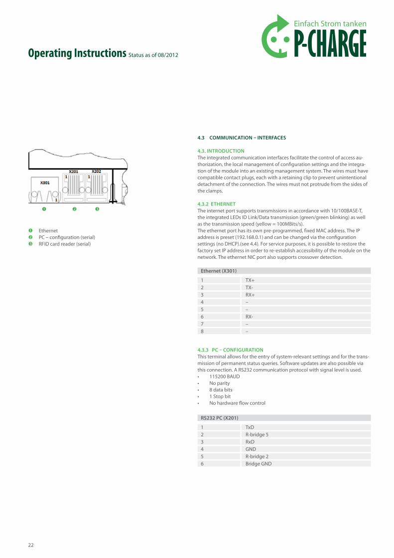
4.3.2 ethernetThe internet port supports transmissions in accordance with 10/100BASE-T, the integrated LEDs ID Link/Data transmission (green/green blinking) as well as the transmission speed (yellow = 100MBits/s). The ethernet port has its own pre-programmed, fixed MAC address. The IP address is preset (192.168.0.1) and can be changed via the configuration settings (no DHCP).(see 4.4). For service purposes, it is possible to restore the factory set IP address in order to re-establish accessibility of the module on the network. The ethernet NIC port also supports crossover detection.
4.3.3 Pc – configuration This terminal allows for the entry of system-relevant settings and for the trans-mission of permanent status queries. Software updates are also possible via this connection. A RS232 communication protocol with signal level is used.• 115200 BAUD• No parity• 8 data bits• 1 Stop bit• No hardware flow control
Operating Instructions Status as of 08/2012
EthernetPC – configuration (serial)RFID card reader (serial)
ethernet (x301)
1 TX+2 TX-3 RX+4 –5 –6 RX-7 –8 –
rS232 Pc (x201)
1 TxD2 R-bridge 53 RxD4 GND5 R-bridge 26 Bridge GND
23
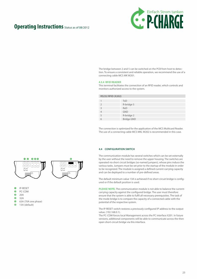
The bridge between 2 and 5 can be switched on the PCB from host to detec-tion. To ensure a consistent and reliable operation, we recommend the use of a connecting cable MCS MK W201.
4.3.4 rfid reader This terminal facilitates the connection of an RFID reader, which controls and monitors authorized access to the system.
The connection is optimized for the application of the MCS Multicard Reader. The use of a connecting cable MCS MKL W202 is recommended in this case.
4.4 configuration SWitch
The communication module has several switches which can be set externally by the user without the need to remove the upper housing. The switches are operated via short circuit bridges (so-named jumpers), whose pins induce the various tasks. Jumpers must be set prior to the startup of the module in order to be recognized. The module is assigned a defined current carrying capacity and can be deployed to a number of pre-defined areas.
The default minimum value 13A is achieved if no short circuit bridge is config-ured or if the default position is used.
PleaSe note. The communication module is not able to balance the current-carrying capacity against the configured bridge. The user must therefore ensure that the system is able to fulfil all necessary prerequisites. The task of the mode bridge is to compare the capacity of a connected cable with the potential of the respective system.
The IP-RESET switch restores a previously configured IP address to the output value. (192.168.0.1).The PC-COM forces local Management across the PC interface X201. In future versions, additional components will be able to communicate across the then open short-circuit bridge via this interface.
Operating Instructions Status as of 08/2012
IP-RESETPC-COM20A32A63A (70A one phase)13A (default)
rS232 rfid (x202)
1 TxD2 R-bridge 53 RxD4 GND5 R-bridge 26 Bridge GND
24
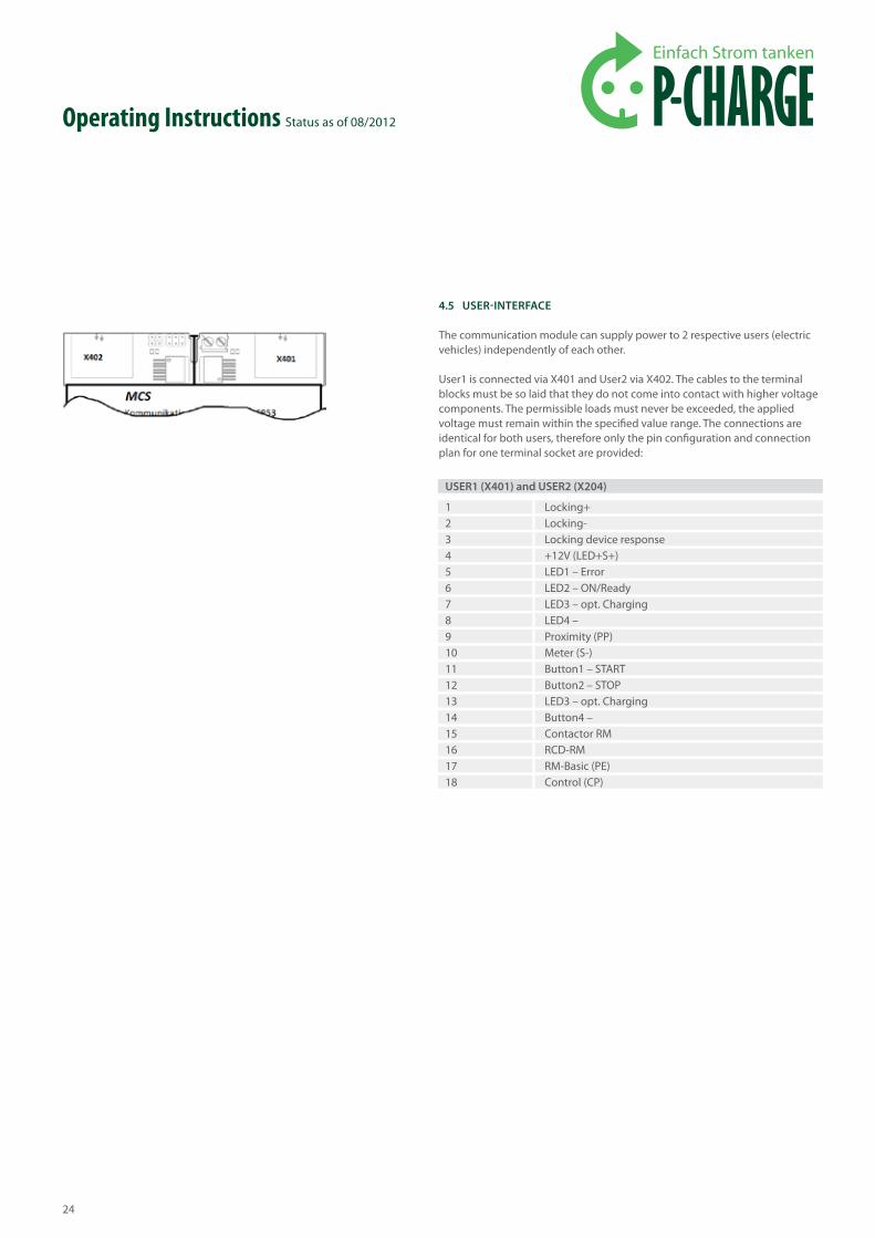
4.5 uSer-interface
The communication module can supply power to 2 respective users (electric vehicles) independently of each other.
User1 is connected via X401 and User2 via X402. The cables to the terminal blocks must be so laid that they do not come into contact with higher voltage components. The permissible loads must never be exceeded, the applied voltage must remain within the specified value range. The connections are identical for both users, therefore only the pin configuration and connection plan for one terminal socket are provided:
Operating Instructions Status as of 08/2012
uSer1 (x401) and uSer2 (x204)
1 Locking+2 Locking-3 Locking device response4 +12V (LED+S+)5 LED1 – Error6 LED2 – ON/Ready7 LED3 – opt. Charging8 LED4 –9 Proximity (PP)10 Meter (S-)11 Button1 – START12 Button2 – STOP13 LED3 – opt. Charging14 Button4 –15 Contactor RM16 RCD-RM17 RM-Basic (PE)18 Control (CP)
25
Operating Instructions Status as of 08/2012
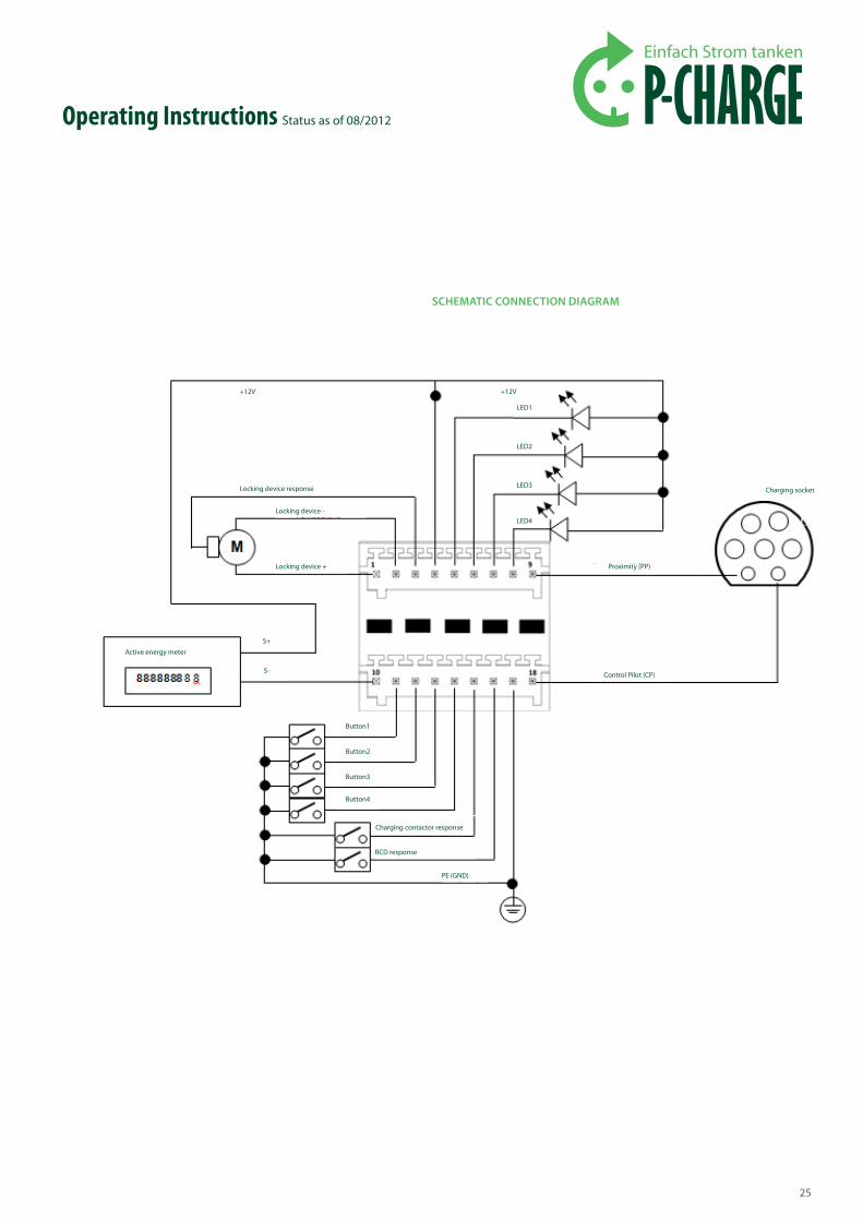
ScheMatic connection diagraM
S+
Active energy meter
Charging socket
Button1
Button2
Button3
Button4
Control Pilot (CP)
Proximity (PP)
+12V +12V
Locking device response
Locking device -
Locking device +
LED2
LED3
LED4
LED1
Charging contactor response
RCD response
PE (GND)
S-

26
Operating Instructions Status as of 08/2012
terminals
1, 2, 3*
4
5, 6, 7, 8,
9
10
11, 12, 13, 14,
15, 16
17
18
Specification
1.2 output: 12V/max.5A must either be fed externally or is achieved via the optional power backup circuit.3 – input: Response input for the latching of the locking device, max. 12V.
output: 12V /max 40mA
output: Open collector - with 1kOhmoutput: Proximity line (PP)
input: 5V < S- < 24V
input: When open - 3.3V, do not apply voltage. When closed - c1mAinput: When open - 3.3V, do not apply voltage. When closed - c1mAPE – Earth-ground conductor
output: 12V < Control Pilot (CP) < -12V
annotations
Activation is dependant upon the locking system used with the charging socket. Generally the line which supplies +Potential for locking and -Potential for unlocking is fed to Terminal 1. The line which supplies potential required for locking (+Potential) and for unlocking (-Potential) is fed to Terminal 2. The latch-ing of the locking device is returned via Terminal 3. The respective locking mechanism can be selected via the con-figuration setting.Supply to the closed LEDs (Anode) and to the impulse counter S+ Typically S+ of an electronic active energy meter is connected with this pin.Connect LED cathodes here, LEDs can be operated directly at Terminal 4.Is connected directly with the PP of the socket outlet. The connected cable is detected.The counting pulse input. Can be connected directly to an S-output of an electronic active energy meter.PleaSe note. S+ must comply with the range value. Ideally S+ should be clamped to Terminal 4 insofar as S+ pre-sents no additional loads.Push-button inputs, voltage free against PE is recognized as a key-press.
Return inputs from the user contactor and from the RCD circuit; voltage free against PE is recognized as a response.This connection can be used as reference potential for ter-minals 11-16. This is connected internally with PE.Is connected directly with the CP of the socket outlet.
*The locking mechanism varies from manufacturer to manufacturer, here a selection of activation and configura-tion options. (See table right).

27
Electrical contact is applied to the terminal socket (viewed here from the front) via a terminal block - ideally ordered together with the module. It should be noted that one terminal block is required for each row (Pins 1-9 and Pins 10-18 respectively).
4.6 12v - SuPPly
An external 12V supply (+/- 5%) can be saved via the terminal socket X501 whereby only one power-limited source can be used in accordance with EN60950-1.
This serves to provide the integrated locking mechanism with the neces-sary power it needs to operate. This buffer also provides the module with an emergency supply of power for a short time following a network outage. The module acknowledges a power outage and triggers an emergency release.
PleaSe note. This function is not designed to provide a continual supply of power to the module during a power outage. It serves solely to terminate a open charging session safely and to secure any data. Where there is suffi-cient voltage, the firmware terminates the charging and attempts to save all relevant data, whereupon it closes all contacts and opens the latching device. The connected power supply must be capable of providing full capacity power over a period of min. 200 ms per connected user. This time period can be determined from the HOLD-UP time in the data sheet to the power supply.
4.7 PoWer-BackuP
The user can also use the EWS Box P with integrated Power Backup circuit for the provision of energy to the locking system. In an idle state this circuit board collects sufficient energy to activate the locking device.The circuit board is positioned (with the help of channel guides in the upper housing) such that the terminal sockets and plugs contact correctly.
On the upper side of the Power Backup, 2 LEDs display the functionality of the circuit board. The green LED documents the circuit board operation, the red LED displays the charging process. As long as the charging session is in progress, (red LED is active), there is insufficient surplice energy available to release the lock-ing device. The module monitors this state and drives the required amount of energy to the locking mechanism at the correct time (red LED off).
Operating Instructions Status as of 08/2012
Pins on the locking mechanism and selection of locking/response mechanism
Pins on communication module
MennekeSmotorisch/impuls
Locking+ (1)Locking- (2)Response (3)
Balsmotorisch/impuls
132
Walthermotorisch/lowaktiv
31Addtional RM cableWhite on +12VBlue is return
0V+12V

© S
chle
tter G
mbH
, 201
2, I8
0002
5GB
, V2
Further P-CHARGE productsand detailed product information can be found under www.p-charge.eu
A product of Schletter GmbH | Gewerbegebiet an der B15 | Alustraße 1 | 83527 Kirchdorf / Haag i. OB | www.schletter.euSubject to technical modifi cations and printing errors. Status as of 08/2012
Mounting of the product and connection to the grid must be carried out exclusively by qualifi ed personnel. The product requires regular maintenance in accordance with the service information included on delivery. We recommend that maintenance of the product be carried out by appropriately trained experts. We accept no liability for damage of any kind not covered by the General Terms and Conditions; particularly for damage caused by vandalism, lightning/overvoltage, nor for consequential costs for automobiles / vehicles nor according to technical connection regula-tions. In the event of a warranty claim, the company Schletter GmbH shall bear the costs required for transport, travel, labour and materials only; excluded are the additional and potentially substantial costs incurred for transfer of the object to a location other than the target site. In the event of a warranty claim, the product must be returned to the company Schletter GmbH for fault diagnosis and supplementary performance if required. The General Terms and Conditions of Sale and Supply of Schletter GmbH (AGB) shall apply here. These can be referenced on the internet under http://www.schletter.de/588-0-AGB.html. Clause 10 of the AGB is not applicable in this case.


![EWS [Compatibility Mode]](https://static.fdocuments.us/doc/165x107/54673170af795974338b5529/ews-compatibility-mode.jpg)