Operating Instructions - SICK
70
OPERATING INSTRUCTIONS OD1000 Displacement measurement sensor
Transcript of Operating Instructions - SICK
O P E R A T I N G I N S T R U C T I O N S
OD1000
Displacement measurement sensor

Product described
OD1000
Manufacturer
SICK AGErwin-Sick-Str. 179183 WaldkirchGermany
Legal information
This work is protected by copyright. Any rights derived from the copyright shall bereserved for SICK AG. Reproduction of this document or parts of this document is onlypermissible within the limits of the legal determination of Copyright Law. Any modifica‐tion, abridgment or translation of this document is prohibited without the express writ‐ten permission of SICK AG.
The trademarks stated in this document are the property of their respective owner.
© SICK AG. All rights reserved.
Original document
This document is an original document of SICK AG.
2 O P E R A T I N G I N S T R U C T I O N S | OD1000 8019642/18JN/2020-07-01 | SICKSubject to change without notice

Contents
1 About this document........................................................................ 61.1 Information on the operating instructions.............................................. 61.2 Explanation of symbols............................................................................ 61.3 Further information................................................................................... 71.4 SICK service.............................................................................................. 7
2 Safety information............................................................................ 82.1 Intended use............................................................................................. 82.2 Improper use............................................................................................. 82.3 Internet protocol (IP) technology.............................................................. 82.4 Limitation of liability................................................................................. 82.5 Modifications and conversions................................................................ 92.6 Requirements for skilled persons and operating personnel.................. 92.7 Operational safety and particular hazards.............................................. 102.8 Warning signs on the device.................................................................... 10
3 Product description........................................................................... 123.1 Product ID.................................................................................................. 123.2 Scope of delivery....................................................................................... 133.3 Product characteristics............................................................................ 133.4 Setup and dimensions............................................................................. 14
4 Transport and storage....................................................................... 154.1 Transport................................................................................................... 154.2 Unpacking.................................................................................................. 154.3 Transport inspection................................................................................. 154.4 Storage...................................................................................................... 15
5 Mounting............................................................................................. 175.1 Mounting instructions............................................................................... 175.2 Mounting device....................................................................................... 17
6 Electrical installation........................................................................ 186.1 Safety......................................................................................................... 186.2 Wiring instructions.................................................................................... 186.3 Connecting the device electrically........................................................... 20
7 Operation............................................................................................ 227.1 General notes............................................................................................ 227.2 Control elements and status indicators.................................................. 22
7.2.1 Indicator lights......................................................................... 227.2.2 Operating buttons.................................................................... 23
7.3 Operating concept.................................................................................... 23
8 Operation via display........................................................................ 24
CONTENTS
8019642/18JN/2020-07-01 | SICK O P E R A T I N G I N S T R U C T I O N S | OD1000 3Subject to change without notice

8.1 Menu structure and parameter description............................................ 248.1.1 Main display level and main menu......................................... 248.1.2 Measurement menu group..................................................... 258.1.3 I/O interface menu group: Q1 output..................................... 268.1.4 I/O interface menu group: Q2/Qa output, In1 input............. 278.1.5 Device menu group.................................................................. 288.1.6 Communication menu group.................................................. 288.1.7 Info menu group...................................................................... 28
8.2 Main display level..................................................................................... 288.3 Measurement............................................................................................ 29
8.3.1 Application settings................................................................. 298.3.2 Default settings........................................................................ 34
8.4 I/O interface.............................................................................................. 398.4.1 Q1 output................................................................................. 398.4.2 Q2 / Qa output.......................................................................... 468.4.3 In1 input................................................................................... 48
8.5 Device........................................................................................................ 538.5.1 User level.................................................................................. 538.5.2 Reset........................................................................................ 538.5.3 Saving customer settings........................................................ 548.5.4 Language.................................................................................. 548.5.5 Display settings........................................................................ 548.5.6 Measurement laser................................................................. 55
8.6 Communication......................................................................................... 558.7 Info............................................................................................................. 55
8.7.1 Firmware verification............................................................... 558.7.2 Serial number.......................................................................... 568.7.3 Sensor operating hours........................................................... 568.7.4 Laser operating hours............................................................. 568.7.5 Sensor status........................................................................... 568.7.6 Part number............................................................................. 56
9 Operation via IO-Link........................................................................ 589.1 Process data............................................................................................. 589.2 Device data............................................................................................... 58
10 Operation via SOPAS ET................................................................... 59
11 Maintenance...................................................................................... 6111.1 Cleaning..................................................................................................... 6111.2 Maintenance plan..................................................................................... 61
12 Troubleshooting................................................................................. 6212.1 General faults, warnings, and errors....................................................... 6212.2 Detecting and displaying errors............................................................... 6212.3 Information for service cases.................................................................. 63
CONTENTS
4 O P E R A T I N G I N S T R U C T I O N S | OD1000 8019642/18JN/2020-07-01 | SICKSubject to change without notice

12.4 Returns...................................................................................................... 6312.5 Repairs...................................................................................................... 6412.6 Disposal..................................................................................................... 64
13 Technical data.................................................................................... 6513.1 Mechanics/electronics............................................................................. 6513.2 Performance............................................................................................. 6513.3 Interfaces.................................................................................................. 6613.4 Ambient data............................................................................................. 67
14 Accessories........................................................................................ 68
15 Annex.................................................................................................. 6915.1 EU declaration of conformity / Certificates............................................. 6915.2 Licenses.................................................................................................... 69
CONTENTS
8019642/18JN/2020-07-01 | SICK O P E R A T I N G I N S T R U C T I O N S | OD1000 5Subject to change without notice

1 About this document
1.1 Information on the operating instructions
These operating instructions provide important information on how to use devices fromSICK AG.
Prerequisites for safe work are:
• Compliance with all safety notes and handling instructions supplied.• Compliance with local work safety regulations and general safety regulations for
device applications
The operating instructions are intended to be used by qualified personnel and electricalspecialists.
NOTERead these operating instructions carefully to familiarize yourself with the device and itsfunctions before commencing any work.
The operating instructions are an integral part of the product. Store the instructions inthe immediate vicinity of the device so they remain accessible to staff at all times.Should the device be passed on to a third party, these operating instructions should behanded over with it.
These operating instructions do not provide information on operating the machine orsystem in which the device is integrated. For information about this, refer to the operat‐ing instructions of the specific machine.
1.2 Explanation of symbols
Warnings and important information in this document are labeled with symbols. Signalwords introduce the instructions and indicate the extent of the hazard. To avoid acci‐dents, damage, and personal injury, always comply with the instructions and act care‐fully.
DANGER… indicates a situation of imminent danger, which will lead to a fatality or seriousinjuries if not prevented.
WARNING… indicates a potentially dangerous situation, which may lead to a fatality or seriousinjuries if not prevented.
CAUTION… indicates a potentially dangerous situation, which may lead to minor/slight injuries ifnot prevented.
NOTICE… indicates a potentially harmful situation, which may lead to material damage if notprevented.
NOTE… highlights useful tips and recommendations as well as information for efficient andtrouble-free operation.
1 ABOUT THIS DOCUMENT
6 O P E R A T I N G I N S T R U C T I O N S | OD1000 8019642/18JN/2020-07-01 | SICKSubject to change without notice

1.3 Further information
NOTEFurther documentation for the device can be found on the online product page at:
• www.sick.com/OD1000
There, additional information has been provided depending on the product, such as:
• Model-specific online data sheets for device types, containing technical data,dimensional drawing, and specification diagrams
• EU declarations of conformity for the product family• Dimensional drawings and 3D CAD dimension models of the device types in vari‐
ous electronic formats• Other publications related to the devices described here• Publications dealing with accessories
1.4 SICK service
If you require any technical information, our SICK Service will be happy to help. To findyour agency, see the final page of this document.
NOTEBefore calling, make a note of all type label data such as type code, serial number, etc.,to ensure faster processing.
ABOUT THIS DOCUMENT 1
8019642/18JN/2020-07-01 | SICK O P E R A T I N G I N S T R U C T I O N S | OD1000 7Subject to change without notice

2 Safety information
2.1 Intended use
The displacement measurement sensor is an opto-electronic measuring device and isused for optical, non-contact distance measurement of objects.
The required optical properties of the object that will be detected are specified in thetechnical data section of this document.
SICK AG assumes no liability for losses or damage arising from the use of the product,either directly or indirectly. This applies in particular to use of the product that does notconform to its intended purpose and is not described in this documentation.
2.2 Improper use
Any use outside of the stated areas, in particular use outside of the technical specifica‐tions and the requirements for intended use, will be deemed to be incorrect use.
• The device does not constitute a safety component in accordance with the respec‐tive applicable safety standards for machines.
• The device must not be used in explosion-hazardous areas, in corrosive environ‐ments or under extreme environmental conditions.
• Any use of accessories not specifically approved by SICK AG is at your own risk.
WARNINGDanger due to improper use!Any improper use can result in dangerous situations.Therefore, observe the following information:
■ Product should be used only in accordance with its intended use.■ All information in these operating instructions must be strictly observed.■ Shut down the product immediately in case of damage.
2.3 Internet protocol (IP) technology
NOTESICK uses standard IP technology in its products. The emphasis is placed on availabilityof products and services.SICK always assumes the following prerequisites:
• The customer ensures the integrity and confidentiality of the data and rightsaffected by its own use of the aforementioned products.
• In all cases, the customer implements the appropriate security measures, such asnetwork separation, firewalls, virus protection, and patch management.
2.4 Limitation of liability
Relevant standards and regulations, the latest technological developments, and ourmany years of knowledge and experience have all been taken into account when com‐piling the data and information contained in these operating instructions. The manufac‐turer accepts no liability for damage caused by:
■ Non-adherence to the product documentation (e.g., operating instructions)■ Incorrect use■ Use of untrained staff■ Unauthorized conversions or repair
2 SAFETY INFORMATION
8 O P E R A T I N G I N S T R U C T I O N S | OD1000 8019642/18JN/2020-07-01 | SICKSubject to change without notice

■ Technical modifications■ Use of unauthorized spare parts, consumables, and accessories
With special variants, where optional extras have been ordered, or owing to the latesttechnical changes, the actual scope of delivery may vary from the features and illustra‐tions shown here.
2.5 Modifications and conversions
NOTICEModifications and conversions to the device may result in unforeseeable dangers.
Interrupting or modifying the device or SICK software will invalidate any warranty claimsagainst SICK AG. This applies in particular to opening the housing, even as part ofmounting and electrical installation.
2.6 Requirements for skilled persons and operating personnel
WARNINGRisk of injury due to insufficient training.Improper handling of the device may result in considerable personal injury and materialdamage.
■ All work must only ever be carried out by the stipulated persons.
This product documentation refers to the following qualification requirements for thevarious activities associated with the device:
■ Instructed personnel have been briefed by the operator about the tasks assignedto them and about potential dangers arising from improper action.
■ Skilled personnel have the specialist training, skills, and experience, as well asknowledge of the relevant regulations, to be able to perform tasks delegated tothem and to detect and avoid any potential dangers independently.
■ Electricians have the specialist training, skills, and experience, as well as knowl‐edge of the relevant standards and provisions, to be able to carry out work on elec‐trical systems and to detect and avoid any potential dangers independently. Theelectrician must comply with the provisions of the locally applicable work safetyregulation.
The following qualifications are required for various activities:
Table 1: Activities and technical requirements
Activities Qualification
Mounting, maintenance ■ Basic practical technical training■ Knowledge of the current safety regulations in the workplace
Electrical installation,device replacement
■ Practical electrical training■ Knowledge of current electrical safety regulations■ Knowledge of the operation and control of the devices in their
particular application
Commissioning, configura‐tion
■ Basic knowledge of the WindowsTM operating system in use■ Basic knowledge of the design and setup of the described con‐
nections and interfaces■ Basic knowledge of data transmission
SAFETY INFORMATION 2
8019642/18JN/2020-07-01 | SICK O P E R A T I N G I N S T R U C T I O N S | OD1000 9Subject to change without notice

Activities Qualification
Operation of the device forthe particular application
■ Knowledge of the operation and control of the devices in theirparticular application
■ Knowledge of the software and hardware environment for theparticular application
2.7 Operational safety and particular hazards
Please observe the safety notes and the warnings listed here and in other chapters ofthis product documentation to reduce the possibility of risks to health and avoid dan‐gerous situations.
CAUTIONOptical radiation: Laser class 1The accessible radiation does not pose a danger when viewed directly for up to 100seconds. It may pose a danger to the eyes and skin in the event of incorrect use.
■ Do not open the housing. Opening the housing may increase the level of risk.
■ Current national regulations regarding laser protection must be observed.
Caution – Use of controls or adjustments or performance of procedures other thanthose specified herein may result in hazardous radiation exposure.
WARNINGElectrical voltage!Electrical voltage can cause severe injury or death.
■ Work on electrical systems must only be performed by qualified electricians.■ The power supply must be disconnected when attaching and detaching electrical
connections.■ The product must only be connected to a voltage supply as set out in the require‐
ments in the operating instructions.■ National and regional regulations must be complied with.■ Safety requirements relating to work on electrical systems must be complied with.
WARNINGRisk of injury and damage caused by potential equalization currents!Improper grounding can lead to dangerous equipotential bonding currents, which mayin turn lead to dangerous voltages on metallic surfaces, such as the housing. Electricalvoltage can cause severe injury or death.
■ Work on electrical systems must only be performed by qualified electricians.■ Follow the notes in the operating instructions.■ Install the grounding for the product and the system in accordance with national
and regional regulations.
2.8 Warning signs on the device
A visible red laser is installed in the device. The laser corresponds to laser class 1. Thehousing is labeled with a warning sign.
LASER
1
Figure 1: Warning sign on the device: LASER RADIATION: laser class 1
2 SAFETY INFORMATION
10 O P E R A T I N G I N S T R U C T I O N S | OD1000 8019642/18JN/2020-07-01 | SICKSubject to change without notice

SAFETY INFORMATION 2
8019642/18JN/2020-07-01 | SICK O P E R A T I N G I N S T R U C T I O N S | OD1000 11Subject to change without notice

3 Product description
3.1 Product ID
Type label
The following information can be read off the device from the type label:
3
5
6
7
8
9
à
ß
4
á
SICK AG
D-79183 Waldkirch
Made in GermanyOD1000
OD1000-6001R15
1 075 638
SN16100001
MAR 2016
EN/IEC 60825-1:2014
Complies with 21 CFR
1040.10 and 1040.11
except for deviations
pursuant to laser
notice No. 50, dated
June 24, 2007
CLASS 1 LASER PRODUCT
DC 18 - 30 Vdc class 2
Qout: < 100 mA
QAout: 4 - 20 mA/0 - 10 V
Amb. Temp.: < 50 °C
Power Con.: < 2.5 W
Enclosure Type: 1
brownblueblackwhitegray
13425
LASER APERTURE
L+MQ1/CQ2/QA
In1
LASER
1
2
25
1
Figure 2: OD1000 type label
1 Approval marks and test symbols2 2D code with part number and serial number3 Laser information4 Laser radiation direction5 IO-Link symbol6 Pin assignment7 Electrical data and environmental data8 Month and year of manufacture9 Serial numberß Part numberà Type codeá Device family
Device display
The following information can be called up using the info menu on the device display:
• Firmware verification• Serial number• Sensor operating hours• Laser operating hours• Sensor status (error history)• Part number
3 PRODUCT DESCRIPTION
12 O P E R A T I N G I N S T R U C T I O N S | OD1000 8019642/18JN/2020-07-01 | SICKSubject to change without notice

3.2 Scope of delivery
Included in scope of delivery:
■ Distance sensor■ Protective caps for connections (on the device)■ Printed Safety Notes, multilingual (brief information and general safety notes)
Accessories
Accessories such as brackets and connecting cables is only delivered if the accessorieshave been ordered separately, see "Accessories", page 68.
3.3 Product characteristics
The displacement measurement sensor uses the triangulation principle for distancemeasurement. The triangulation principle makes it possible to measure the distancebetween the displacement measurement sensor and an object.
Figure 3: Triangulation principle
1 Receiver2 Lens3 Object4 Laser
A point of light is projected onto the measuring object. The light reflected is captured bya light-sensitive receiver at a specific angle. Based on the angle between the send andreceive direction, the position of the object is triangulated (lat. Triangulum: triangle).
The distance determined is transmitted via the IO-Link interface. The analog signal out‐put converts the distance value into an output signal proportional to the distance(switchable: mA/V).
Digital outputs can be used to monitor when configured switching threshold/distancevalues have been reached. The “Distance to the object”, “Window”, and “ObSB” switch‐ing functions are supported.
Measured distance values can be visualized and parameter settings can be madeusing the graphical OLED display. Alternatively, the displacement measurement sensorcan be configured via the IO-Link interface in conjunction with an IO-Link master. TheSOPAS user interface can be used for configuration as well. This process also takesplace via the IO-Link interface in conjunction with an IO-Link master. For additionalinformation visit:
www.sick.com/SOPAS_ET
PRODUCT DESCRIPTION 3
8019642/18JN/2020-07-01 | SICK O P E R A T I N G I N S T R U C T I O N S | OD1000 13Subject to change without notice

3.4 Setup and dimensions
71
.5 (
2.8
1)
60
.7 (
2.3
9)
58
.55
(2
.31
) 22
.5(0
.89
)
53
.2 (
2.0
9)
11.95(0.47)
∅ 4.5 (0.18)
4.5
(0
.18
)
3 (0.12)
15.2(0.60)
PW
R
Q1
Q2
M12 x
1
2
1
6
9
78
4
5
2
25.9(1.02)
3
Figure 4: structure and device dimensions, unit: mm (inch), decimal separator: period
1 Device zero point (distance = 0 mm)2 Fixing holes (for M4)3 Ventilation opening – do not cover!4 Center of optical axis, receiver5 Center of optical axis, sender6 Male connector, M12, 5-pin, A-coded7 PWR LED green8 Q1 LED, yellow9 Q2 LED, yellowß Display operating elements
3 PRODUCT DESCRIPTION
14 O P E R A T I N G I N S T R U C T I O N S | OD1000 8019642/18JN/2020-07-01 | SICKSubject to change without notice

4 Transport and storage
4.1 Transport
For your own safety, please read and observe the following notes:
NOTICEDamage to the product due to improper transport.
■ The device must be packaged for transport with protection against shock anddamp.
■ Recommendation: Use the original packaging as it provides the best protection.■ Transport should be performed by trained specialist staff only.■ The utmost care and attention is required at all times during unloading and trans‐
portation on company premises.■ Note the symbols on the packaging.■ Do not remove packaging until immediately before you start mounting.
4.2 Unpacking
■ To protect the device against condensation, allow it to equilibrate with the ambienttemperature before unpacking if necessary.
■ Handle the device with care and protect it from mechanical damage.■ To avoid ingress of dust and water, only remove the protective caps of the electri‐
cal connections just before attaching the connecting cable.
4.3 Transport inspection
Immediately upon receipt in Goods-in, check the delivery for completeness and for anydamage that may have occurred in transit. In the case of transit damage that is visibleexternally, proceed as follows:
■ Do not accept the delivery or only do so conditionally.■ Note the scope of damage on the transport documents or on the transport com‐
pany's delivery note.■ File a complaint.
NOTEComplaints regarding defects should be filed as soon as these are detected. Damageclaims are only valid before the applicable complaint deadlines.
4.4 Storage
Store the device under the following conditions:
■ Recommendation: Use the original packaging.■ Electrical connections are provided with a protective cap (as in the delivery condi‐
tion).■ Do not store outdoors.■ Store in a dry area that is protected from dust.■ So that any residual damp can evaporate, do not package in airtight containers.■ Do not expose to any aggressive substances.■ Protect from sunlight.■ Avoid mechanical shocks.
TRANSPORT AND STORAGE 4
8019642/18JN/2020-07-01 | SICK O P E R A T I N G I N S T R U C T I O N S | OD1000 15Subject to change without notice

■ Storage temperature: see "Technical data", page 65.■ For storage periods of longer than 3 months, check the general condition of all
components and packaging on a regular basis.
4 TRANSPORT AND STORAGE
16 O P E R A T I N G I N S T R U C T I O N S | OD1000 8019642/18JN/2020-07-01 | SICKSubject to change without notice

5 Mounting
5.1 Mounting instructions
• Observe the technical data.• Protect the sensor from direct sunlight.• To prevent condensation, avoid exposing the device to rapid changes in tempera‐
ture.• The mounting site has to be designed for the weight of the device.• To avoid inaccurate measurements when installing multiple devices: Make sure
that the laser light spot of one device is not in the visible range of another device.• Take into account the device warm-up time of 30 minutes. During the device
warm-up phase, the measured values are subject to an increased variance (tem‐perature drift).
5.2 Mounting device
1. Mount the device using the designated fixing holes, see "Setup and dimensions",page 14.
2. Make the electrical connection. Attach and tighten a voltage-free cable, see "Con‐necting the device electrically", page 20.
3. Switch on the supply voltage.✓ The green operating LED lights up.
The device needs around 10 seconds of initialization time before it is ready foroperation.
4. Align the light spot so that the desired object is measured.
MOUNTING 5
8019642/18JN/2020-07-01 | SICK O P E R A T I N G I N S T R U C T I O N S | OD1000 17Subject to change without notice

6 Electrical installation
6.1 Safety
WARNINGPersonal injury due to improper supply voltage!
■ Only operate the device using safety extra-low voltage and safe electrical insula‐tion as per protection class III.
NOTICEEquipment damage or unpredictable operation due to working with live parts.Working with live parts may result in unpredictable operation.
■ Only carry out wiring work when the power is off.■ Only connect and disconnect electrical connections when the power is off.
6.2 Wiring instructions
NOTEPre-assembled cables can be found online at:
• www.sick.com/OD1000
NOTICEFaults during operation and device or system defects!Incorrect wiring may result in operational faults and defects.
■ Follow the wiring notes precisely.
The electrical connection of the device is configured as an M12 round connector.
The protection class stated in the technical data is achieved only with a screwed plugconnector or protective cap.
Shielding requirements
■ To ensure a fault-free data transmission, an effective and comprehensive shieldingsolution must be implemented.
■ Apply a cable shield at each end, i.e. in the control cabinet and at the device. Thecable shield of the pre-assembled cables is connected to the knurled nut and thusalso to a large area of the device housing.
■ The cable shield in the control cabinet must be connected to a large area of thesignal ground.
■ Take appropriate measures to prevent equipotential bonding currents flowingthrough the cable shield.
■ During installation, pay attention to the different cable groups. The cables aregrouped into the following four groups according to their sensitivity to interferenceor radiated emissions:
° Group 1: cables very sensitive to interference, such as analog measuringcables
° Group 2: cables sensitive to interference, such as device cables, communica‐tion signals, bus signals
6 ELECTRICAL INSTALLATION
18 O P E R A T I N G I N S T R U C T I O N S | OD1000 8019642/18JN/2020-07-01 | SICKSubject to change without notice

° Group 3: cables that are a source of interference, such as control cables forinductive loads and motor brakes
° Group 4: cables that are a powerful source of interference, such as outputcables from frequency inverters, welding system power supplies, powercables
b Cables in groups 1, 2 and 3, 4 must be crossed at right angles (see figure 5).b Route the cables in groups 1, 2 and 3, 4 in different cable channels or use
metallic separators (see figure 6 and see figure 7). This applies particularly ifcables of devices with a high level of radiated emission, such as frequencyconverters, are laid parallel to device cables.
1
2
4
3
1
2
4
3
90
90
Figure 5: Cross cables at right angles
1
2
3
4
Figure 6: Ideal laying – Place cables in different cable channels
1
23
4
Figure 7: Alternative laying – Separate cables with metallic separators
ELECTRICAL INSTALLATION 6
8019642/18JN/2020-07-01 | SICK O P E R A T I N G I N S T R U C T I O N S | OD1000 19Subject to change without notice

Figure 8: Shield connection in plastic housings
NOTEUse an appropriate earthing method to prevent equipotential bonding currents flowingthrough the cable shield. If necessary, ground currents on the EtherNet/IP cabling canbe prevented by using an EtherNet/IP adapter (part no. 2044264).
6.3 Connecting the device electrically
NOTEThe connection diagram, and information on inputs and outputs, can be found on theside plate on the device.
NOTICEAll electrical circuits must be connected to the device with safety extra-low voltage(SELV or PELV).
1. Ensure that the voltage supply is not connected.2. Connect the device according to the connection diagram.3. Observe the wiring instructions, see "Wiring instructions", page 18.
1
4 3
5
2
L+1brn
M3blu
Q1/C4blk
QA/Q2/Q̄12wht
In15gra
Figure 9: Connection diagram, 5-pin male connector
Table 2: Legend for connection diagram
Contact Identification Wire color Description
1 L+ Brown Supply voltage: +18 ... +30 V DC
2 QA/Q2/Q1 White Output 2: analog output / digital output 2(push-pull stage) / not Q1
3 M Blue Supply voltage: 0 V
6 ELECTRICAL INSTALLATION
20 O P E R A T I N G I N S T R U C T I O N S | OD1000 8019642/18JN/2020-07-01 | SICKSubject to change without notice

Contact Identification Wire color Description
4 Q1/C Black Output 1: digital output 1 (push-pullstage) / IO-Link
5 In1 Gray Input 1
ELECTRICAL INSTALLATION 6
8019642/18JN/2020-07-01 | SICK O P E R A T I N G I N S T R U C T I O N S | OD1000 21Subject to change without notice

7 Operation
7.1 General notes
If the device is not able to perform a measurement even though the measuring object iswithin the specified measuring range, check the alignment of the device and optimize itif necessary. In general, adjusting the measuring rate can increase the measuring abil‐ity for very dark objects, for example.
For a successful teach-in operation, the device must be able to measure. The distanceto the teach object must not change during the teach operation. The object must be inthe measuring range. The distance values taught in for the distance near to the sensorand the distance far from the sensor must not be exactly the same during a switchingwindow or the analog scaling.
To prevent EMC interference, observe the wiring instructions. If an environment is dis‐rupted by EMC interference, data output via IO-Link is recommended. If the measuredvalues need to be output via the analog output in an application with this kind of envi‐ronment, use an analog current output. The analog current output is significantly lesssusceptible to EMC interference than a voltage output.
7.2 Control elements and status indicators
7.2.1 Indicator lights
PWR
Q1
Q2
1
4
2
3
1 Status-LED PWR (grün)2 Status-LED Q1 (orange)3 Status-LED Q2 (orange)4 Bedientasten
Table 3: Meaning of the indicator lights
Display Status Meaning
PWR status indicator O Voltage supply available, deviceready for use
o Voltage supply not available
Ö Voltage supply available, deviceready for use, connection to an IO-Link master available
Output display Q1 O Digital output active
o Digital output not active
Output display Q2 O Digital output active or measuredvalue within the scaling range for theanalog output
o Digital output not active or measuredvalue outside the scaling range forthe analog output
7 OPERATION
22 O P E R A T I N G I N S T R U C T I O N S | OD1000 8019642/18JN/2020-07-01 | SICKSubject to change without notice
Display Status Meaning
Output displays Q1 Ö Ö Simultaneous Teach-in operation is carried out
Ö Ö 5 seconds in alter‐nation
Teach-in operation has failed
Ö Ö Permanently inalternation
There is a fault
o Does not light upÖ FlashingO Permanently on
7.2.2 Operating buttons
Pushbutton Function Description
Open menu/confirm
Opens the menu, confirms entries, or switches to the next menulevel of a selected element.Moves the cursor to the right when entering numbers.
Cancel Switches to the previous menu level.Moves the cursor to the left when entering numbers.
Navigate Switches between multiple screens on one menu level.Increases the value when entering numbers.
Navigate Switches between multiple screens on one menu level.Reduces the value when entering numbers.
Activating and deactivating the operating button lock
To prevent accidental operation, lock and unlock the operating buttons using a short‐cut:
b Press and hold the and pushbuttons simultaneously for > 3 seconds.✓ When the pushbutton lock is activated, the padlock symbol appears in the dis‐
play. When the pushbutton lock is deactivated, the padlock symbol is not dis‐played.
NOTEThe operating button lock can also be activated and deactivated via SOPAS ET or IO-Link.
7.3 Operating concept
The device can be operated using the following methods:• Display and operating buttons on the device, see "Operation via display",
page 24.• SOPAS ET user interface (computer), see "Operation via SOPAS ET", page 59.• IO-Link, see "Operation via IO-Link", page 58.
OPERATION 7
8019642/18JN/2020-07-01 | SICK O P E R A T I N G I N S T R U C T I O N S | OD1000 23Subject to change without notice

8 Operation via display
NOTEOnly certain functions are available depending on the user level set (see see "Userlevel", page 53):• Easy: frequently required functions (factory setting)• Advanced: all available functions
8.1 Menu structure and parameter description
8.1.1 Main display level and main menu
8 OPERATION VIA DISPLAY
24 O P E R A T I N G I N S T R U C T I O N S | OD1000 8019642/18JN/2020-07-01 | SICKSubject to change without notice

8.1.2 Measurement menu group
OPERATION VIA DISPLAY 8
8019642/18JN/2020-07-01 | SICK O P E R A T I N G I N S T R U C T I O N S | OD1000 25Subject to change without notice
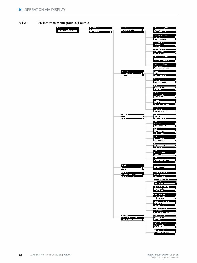
8.1.3 I/O interface menu group: Q1 output
8 OPERATION VIA DISPLAY
26 O P E R A T I N G I N S T R U C T I O N S | OD1000 8019642/18JN/2020-07-01 | SICKSubject to change without notice

8.1.4 I/O interface menu group: Q2/Qa output, In1 input
OPERATION VIA DISPLAY 8
8019642/18JN/2020-07-01 | SICK O P E R A T I N G I N S T R U C T I O N S | OD1000 27Subject to change without notice

8.1.5 Device menu group
8.1.6 Communication menu group
8.1.7 Info menu group
8.2 Main display level
As soon as voltage is supplied to the device, the display shows the main display leveland a measured value is displayed.
8 OPERATION VIA DISPLAY
28 O P E R A T I N G I N S T R U C T I O N S | OD1000 8019642/18JN/2020-07-01 | SICKSubject to change without notice
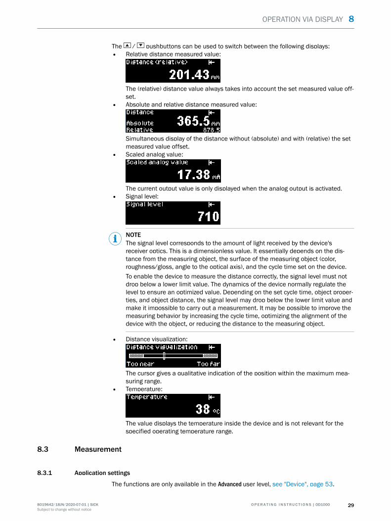
The / pushbuttons can be used to switch between the following displays:• Relative distance measured value:
The (relative) distance value always takes into account the set measured value off‐set.
• Absolute and relative distance measured value:
Simultaneous display of the distance without (absolute) and with (relative) the setmeasured value offset.
• Scaled analog value:
The current output value is only displayed when the analog output is activated.• Signal level:
NOTEThe signal level corresponds to the amount of light received by the device'sreceiver optics. This is a dimensionless value. It essentially depends on the dis‐tance from the measuring object, the surface of the measuring object (color,roughness/gloss, angle to the optical axis), and the cycle time set on the device.To enable the device to measure the distance correctly, the signal level must notdrop below a lower limit value. The dynamics of the device normally regulate thelevel to ensure an optimized value. Depending on the set cycle time, object proper‐ties, and object distance, the signal level may drop below the lower limit value andmake it impossible to carry out a measurement. It may be possible to improve themeasuring behavior by increasing the cycle time, optimizing the alignment of thedevice with the object, or reducing the distance to the measuring object.
• Distance visualization:
The cursor gives a qualitative indication of the position within the maximum mea‐suring range.
• Temperature:
The value displays the temperature inside the device and is not relevant for thespecified operating temperature range.
8.3 Measurement
8.3.1 Application settings
The functions are only available in the Advanced user level, see "Device", page 53.
OPERATION VIA DISPLAY 8
8019642/18JN/2020-07-01 | SICK O P E R A T I N G I N S T R U C T I O N S | OD1000 29Subject to change without notice

8.3.1.1 Distance range
The “Distance range” function can be used to define an evaluation range in which thedevice measures object distances. All surrounding ranges are blanked. A typical appli‐cation is the blanking of a transparent protective screen fitted between the object andthe device.
During configuration, note that the application must take into account a tolerancerange of 15 mm outside the set limits of the distance range. Reliable blanking anddetection of objects cannot be guaranteed within this tolerance range.
Max. measuring range
Transparentscreen
Distance rangeNear limit Far limit
15 mmTolerance window
15 mmTolerance window
Reliable detectionReliable blanking Reliableblanking
Measuring object
Figure 10: Blanking of a transparent protective screen by establishing the near limit and far limitof the distance range, taking into account the tolerance ranges
1 Reliable blanking2 Reliable detection3 Measuring object4 Distance range5 Far limit6 Tolerance window7 Maximum measuring range8 Near limit9 Transparent screen
Near limit and far limit
The near limit and far limit values are the distances in mm which define the limits of theevaluation range.
NOTEAs there are limited discretization steps, the device transfers the limit values entered tothe next possible distance values (mm). The recalculated value is adopted by the deviceand is also shown on the display.
Simple configuration of the distance range is also possible via the SOPAS ET software,see "Operation via SOPAS ET", page 59.
> Measurement > > Application settings > > Distance range > > Near limit >
> Measurement > > Application settings > > Distance range > > Far limit >
8 OPERATION VIA DISPLAY
30 O P E R A T I N G I N S T R U C T I O N S | OD1000 8019642/18JN/2020-07-01 | SICKSubject to change without notice

The near limit and far limit parameters are device-dependent and are set to the physicallimit in the factory settings. The functionality and linear behavior are available in thevalid measuring range of 200 to 1,000 mm.
8.3.1.2 Edge height change
The edge height change function supplies a switching signal at the set device output assoon as there is a change in value between two measured values. A typical applicationfor this function is counting shingles in printing applications. The device takes on thecomplex evaluation tasks carried out by the control system.
To use the edge height change function, configure the following settings on the device:• Select the function on the digital output, see "Edge height change", page 45• Set a fixed cycle time (recommended), see "Cycle time", page 34• Set the minimum and maximum height change, see "Edge height change",
page 31• Set the hysteresis (if necessary), see "Edge height change", page 31• Set the change direction (if necessary), see "Edge height change", page 31• Set the cycle offset (if necessary), see "Cycle time", page 34
Min. / max. height change
The min. height change and max. height change values define the smallest and largest dif‐ference in mm. The two measured values must differ by this amount for there to be anedge height change. The function only takes into account the difference between twomeasured values and is independent of the absolute distance of the object.
> Measurement > > Application settings > > Edge height change > > Min. height change >
> Measurement > > Application settings > > Edge height change > > Max. height change >
Parameter Factory setting
Min. height change:-9,999.9 mm ... +9,999.9 mm
10 mm
Max. height change:-9,999.9 mm ... +9,999.9 mm
100 mm
Hysteresis
Hysteresis is the difference in distance between the switch-on and switch-off points.The hysteresis is necessary to ensure stable switching when the measured distancefluctuates around the switching point that has been set. Hysteresis can be configured
OPERATION VIA DISPLAY 8
8019642/18JN/2020-07-01 | SICK O P E R A T I N G I N S T R U C T I O N S | OD1000 31Subject to change without notice

freely with most distance sensors and is stated in mm. More precise switching isachieved by setting a lower value. Set a higher value for the hysteresis to ensure morestable switching or reduce the probability of a faulty switch.
> Measurement > > Application settings > > Edge height change > > Hysteresis >
Parameter Factory setting
0 mm ... +100 mm 0.5 mm
Change direction
The change direction value defines whether changes in measured values which result insmaller or larger distances are detected in both directions.
• both: All changes in measured values within the set limits are detected.• Positive: Only changes in measured values within the set limits which result in
larger distances are detected (description applies to factory setting).• Negative: Only changes in measured values within the set limits which result in
smaller distances are detected (description applies to factory setting).
> Measurement > > Application settings > > Edge height change > > Change direction >
Parameter Factory setting
Both, positive, negative Both
Cycle offset
The cycle offset value specifies which previous output value is compared with the valuecurrently measured.
NOTEWe recommend using the edge height change operating mode with a fixed cycle time,see "Cycle time", page 34. This ensures time consistency for the output of measuredvalues. In the Auto operating mode, fluctuating remission values of the object surfacecan change the cycle time of the device, which means that reliable detection cannot beguaranteed in the case of high detection speeds or small structures.
> Measurement > > Application settings > > Edge height change > > Cycle offset >
Parameter Factory setting
1 ... 256 8
8 OPERATION VIA DISPLAY
32 O P E R A T I N G I N S T R U C T I O N S | OD1000 8019642/18JN/2020-07-01 | SICKSubject to change without notice

Examples of the digital output for the edge height change function
1
2
9
ß
à
4
5
8
6 67
1234 0
1234 0
1234 0
1234 0
t
3
Figure 11: Edge height change - duration of the change in measured value is longer than thetime span of the cycle offset
1 Cycle offset: 4, without measured value filter2 Cycle time fixed, e.g. 1 ms3 Signal diagram for real distance4 Max. limit value for edge height change (mm)5 Min. limit value for edge height change (mm)6 Change in measured value, from large to small distance7 Change in measured value, from small to large distance8 Signal diagram for digital output9 “Change direction: both” parameterß “Change direction: negative” parameterà “Change direction: positive” parameter
OPERATION VIA DISPLAY 8
8019642/18JN/2020-07-01 | SICK O P E R A T I N G I N S T R U C T I O N S | OD1000 33Subject to change without notice

9
ß
à
2
t
11234 0
1234 0
1234 0
1234 0
4
53
8
76 7 6 6 7
Figure 12: Edge height change - duration of the change in measured value is shorter than thetime span of the cycle offset
1 Cycle offset: 4, without measured value filter2 Cycle time fixed, e.g. 1 ms3 Signal diagram for real distance4 Max. limit value for edge height change (mm)5 Min. limit value for edge height change (mm)6 Change in measured value, from large to small distance7 Change in measured value, from small to large distance8 Signal diagram for digital output9 “Change direction: both” parameterß “Change direction: negative” parameterà “Change direction: positive” parameter
8.3.2 Default settings
8.3.2.1 Cycle time
The cycle time defines the interval in which the device performs a measurement andessentially corresponds to the output rate of the measured values.
Available modes:• Auto mode: The device adjusts itself to the maximum speed at which the device
can achieve a stable measurement, depending on the object surface.
NOTEIn the Auto operating mode, the cycle time is adjusted dynamically so the outputrate of the measured values can vary over time.
8 OPERATION VIA DISPLAY
34 O P E R A T I N G I N S T R U C T I O N S | OD1000 8019642/18JN/2020-07-01 | SICKSubject to change without notice

• Fixed setting: The device uses the set cycle time as a maximum, regardless of theobject surface. The output rate of the measured values corresponds to the setvalue and remains constant.
NOTEIf the remission properties of the object are not sufficient to perform a valid mea‐surement, the device outputs the value of an incorrect measurement, see "Actionin case of incorrect measurements", page 38.
> Measurement > > Default settings > > Cycle time >
Parameter Factory setting
Auto, 0.3 ms, 0.5 ms, 1 ms, 5 ms, 10 ms Auto
8.3.2.2 Measured value filter
The measured value filters are used to optimize the signal diagram in order to simplifythe evaluation by the control system, e.g., for regulation tasks.
Available measured value filters:• Average filter The average filter carries out a moving averaging of the measured
values. The average filter is suitable for smoothing a noisy signal diagram. Thisimproves the repeatability of the measurement.
• Median filter: The moving median filter sorts the measured values according totheir size and selects the middle value from a sequence. The median filter is suit‐able for excluding individual outliers from the calculation of an average value.
Both types of filter affect the response time of the distance sensor.
OPERATION VIA DISPLAY 8
8019642/18JN/2020-07-01 | SICK O P E R A T I N G I N S T R U C T I O N S | OD1000 35Subject to change without notice

Real distance
Measured value without averaging (Avg: OFF)
Output signal
Time t
1
Measured value with median (Avg: 63)2
4
Measured value with averaging (Avg: 64)3
4
3
21
Figure 13: Measured value filter
1 Output signal2 True distance3 Measured value with median (avg: 63)4 Measured value with averaging (avg: 64)5 Measured value without averaging (avg: OFF)6 Time t
> Measurement > > Default settings > > Measured value filter >
Parameter Factory setting
Do not use a filter x
Averaging filter:4, 8, 16, 32, 64, 512
-
Median filter:3, 7, 15, 31, 63, 511
-
8.3.2.3 Bit filter
The bit filter for digital outputs determines how often an identical output state has torecur consecutively before the signal at the digital output changes accordingly.
8 OPERATION VIA DISPLAY
36 O P E R A T I N G I N S T R U C T I O N S | OD1000 8019642/18JN/2020-07-01 | SICKSubject to change without notice

If the defined number is not reached, the digital output remains unchanged. This may,for example, increase the reliability in the application if the distance value fluctuatesaround the selected switching point. This will not affect the cycle time or the outputrate.
> Measurement > > Default settings > > Bit filter >
Parameter Factory setting
On: 1 ... 32, off 2
8.3.2.4 Measuring direction
The function changes the plus/minus sign of the relative distance value depending onthe direction from the center of the measuring range.
• Positive: Distances which are larger than the set zero position of the device areassigned a plus sign. Smaller distances are assigned a minus sign accordingly.
• Negative: Distances which are larger than the set zero position of the device areassigned a minus sign. Smaller distances are assigned a plus sign accordingly.
> Measurement > > Default settings > > Measuring direction >
Parameter Factory setting
Positive, negative Positive
8.3.2.5 Measured value offset
The measured value offset moves the zero point of the device within the maximummeasuring range. This makes it possible to measure absolute distance changes in rela‐tion to an individual reference distance.
NOTEIn the case of all offset settings, the current gradient of the analog characteristic curveremains unchanged.
Setting the measured value offset
A manual measured value offset may be set. The distance value that the distance sen‐sor outputs and that is evaluated in the switching functions takes into account the setoffset. Only absolute measured values are transferred via IO-Link communication.
Table 4: Example of measured value offset
Distance (absolute) Analog output Set offset
In factory setting 600.0 mm 12.00 mA -600.0 mm
With offset input+100.0 mm
600.0 mm 14.00 mA -500.0 mm
> Measurement > > Default settings > > Measured value offset > > Set measured valueoffset >
OPERATION VIA DISPLAY 8
8019642/18JN/2020-07-01 | SICK O P E R A T I N G I N S T R U C T I O N S | OD1000 37Subject to change without notice

Parameter Factory setting
-1,000.0 m ... +1,000.0 m -600.0 m
Teaching in the zero point
The current distance is taught in as a new zero point (reference point). When the analogoutput is activated, the analog value is set to the center of the measuring range at thisdistance (12 mA / 5 V).
> Measurement > > Default settings > > Measured value offset > > Teach in zero point >
NOTEThis function can also be executed using a shortcut:
b In the main display level, press and hold the pushbutton for > 3 seconds untilthe relative distance value is set to 0.0 mm
Resetting the zero point
This resets the zero point to the center of the measuring range according to the factorysetting.
> Measurement > > Default settings > > Measured value offset > > Reset zero point >
NOTEThis function can also be executed using a shortcut:
b In the main display level, press and hold the pushbutton for > 6 seconds untilthe relative distance value is set to the factory setting.
8.3.2.6 Action in case of incorrect measurements
If a distance measurement cannot be run, an error is output. Possible causes of theerror:
• The measuring object is outside of the measuring range.• The light signal received by the device is not strong enough.• The laser is switched off.
You can configure the device behavior for the event that no measurement is possible.The following options are available:
8 OPERATION VIA DISPLAY
38 O P E R A T I N G I N S T R U C T I O N S | OD1000 8019642/18JN/2020-07-01 | SICKSubject to change without notice

• Substitute value in the event of an error: A numerical value can be entered whichis output when no measurement is possible.
• Error mode > User-defined values: If no measurement is possible, the set Substi‐tute value in the event of an error (see above) is displayed and held until a validmeasured value is available again.
• Error mode > Hold last value: If no measurement is possible, the last valid mea‐sured value is displayed and held until a valid measured value is available again.
• Error mode > Hold last value for a defined time: If no measurement is possible,the last valid measured value is displayed and held for the time set under Errorsuppression time (see below). Once this time has elapsed, the set Substitutevalue in the event of an error (see above) is displayed and held until a valid mea‐sured value is available again.
• Error suppression time: It is possible to set a time for which the last valid mea‐sured value is displayed and held if the error mode Hold last value for a definedtime (see above) is activated.
> Measurement > > Default settings > > Action in case of incorrect measurements >
Parameter Factory setting
Substitute value in the event of an error:-3,276.8 m ... +3,276.7 m
+3,276.7 m
Error mode:User-defined valuesHold last valueHold last value for a defined time
✓--
Error suppression time:0001 ms ... 9,999 ms
1 ms
8.4 I/O interface
8.4.1 Q1 output
The Q1 output is purely a digital output. In addition, the output serves as a communica‐tion line for bidirectional data transmission when using the IO-Link interface.
The Q1 output of the OD1000 provides the following switching modes:• DtO, distance to object (1-point), one switching point• Window, two switching points• ObSB, object between sensor (device) and background, one switching point• Alarm (only in Advanced user level)• Signal level warning (only in Advanced user level)• Edge height change (only in Advanced user level)
The switching modes are explained in the subsequent chapters.
8.4.1.1 Notes on the measuring and setting functions
The following functions can be set independently from each other on both outputsdepending on the selected output function.
Delay mode
Delay mode is used to output the output state change with a time delay or as a shortswitching pulse (1 shot).
OPERATION VIA DISPLAY 8
8019642/18JN/2020-07-01 | SICK O P E R A T I N G I N S T R U C T I O N S | OD1000 39Subject to change without notice

1 2 3
0.5 s
4
0.5 s
t5
0.5 s0.5 sHigh
Low
1 Off: Right after the measured distance has exceeded the specified switching point, thestate of the digital output changes (factory setting).
2 Switch-on delay: The changeover of the digital output from an inactive to an active state istime-delayed. The delay time is adjustable. The changeover from an active to an inactivestate is not delayed.
3 Switch-off delay: The changeover of the digital output from an active to an inactive state istime-delayed. The delay time is adjustable. The changeover from an inactive to an activestate is not delayed.
4 Switch-on/switch-off delay: The changeover from an inactive to an active state and viceversa is time-delayed. The delay time is adjustable.
5 1 shot: Once the switching condition has been met, the digital output changes from aninactive to an active state. The output state remains in an active state for a specifiedperiod regardless of how long the switching condition is met. It does not switch back to aninactive state until this time has elapsed. Any additional changes made to the switchingcondition during this period are still not taken into account.
NOTEFor a combination of switch-on delay and switch-off delay, the following conditionsmust be met:
• Equidistant measuring frequency• Min. 2x measuring frequency• Cycle time must not be set to AUTO.
Active status
The active status describes the relationship between the output state (active or inac‐tive) and the potential present on the digital output (high or low).
> I/O interface > > Q1 output > > Distance to object >
If the Distance to object switching mode is selected, the required settings can be taughtin or set manually. These are described in the following.
8.4.1.2 Distance to object, DtO, single switching point
If the measured distance value has undershot (High Active) or exceeded (Low Active)the switching point, a signal is output.
8 OPERATION VIA DISPLAY
40 O P E R A T I N G I N S T R U C T I O N S | OD1000 8019642/18JN/2020-07-01 | SICKSubject to change without notice

Minimum 1 Maximum 32
1
0
Figure 14: Distance to object or single switching point (normally open – High Active, PNP)
1 Minimum2 Switching point3 Maximum
Minimum 1 Maximum 32
1
0
Figure 15: Distance to object or inverted single switching point (normally closed – Low Active,PNP)
1 Minimum2 Switching point3 Maximum
If the “Distance to object” switching mode is selected, the required settings can betaught in or set manually.
In the Distance to object operating mode, the following settings can be configured:• Teach-in• Manual teach-in• Active status• Hysteresis• Delay mode• Time for delay mode
The possible settings are described below.
Teach-in: A single switching point can be taught in. The switching point is set to the cur‐rent distance at the time the button is pressed.• Q1: If the switching point that has been taught in is undershot, a signal is output.
Thus the output acts as a normally open contact (“High” active status).• Q1not: If the switching point that has been taught in is exceeded, a signal is out‐
put. Thus the output acts as a normally closed contact (“Low” active status).
Manual teach-in: The distance of the switching point can be set manually in 1/10 mm.
Q1 active status: The active status specifies the functionality of the digital output, see"Notes on the measuring and setting functions", page 39.• High: The digital output acts as a normally open contact. If the switching point that
has been taught in is undershot, a signal is output.• Low: The digital output acts as a normally closed contact. If the switching point
that has been taught in is exceeded, a signal is output.
Delay mode• see "Notes on the measuring and setting functions", page 39 .
Time for delay mode• The time for the delay mode can be set manually in ms.
> I/O interface > > Q1 output > > Distance to object >
OPERATION VIA DISPLAY 8
8019642/18JN/2020-07-01 | SICK O P E R A T I N G I N S T R U C T I O N S | OD1000 41Subject to change without notice
Parameter Factory setting
Q1 teach-in:Q1, Q1 not
-
Manual Q1 teach-in:-1,000.0 mm ... +1,000.0 mm
+400 mm
Q1 active status:High, Low
High
Q1 hysteresis:0000.0 mm ... +0100.0 mm
+1.0 mm
Delay mode:OffSwitch-on delaySwitch-off delaySwitch-on/switch-off delay1 shot
✓----
Time for delay mode:0000 ms ... 9,999 ms
100 ms
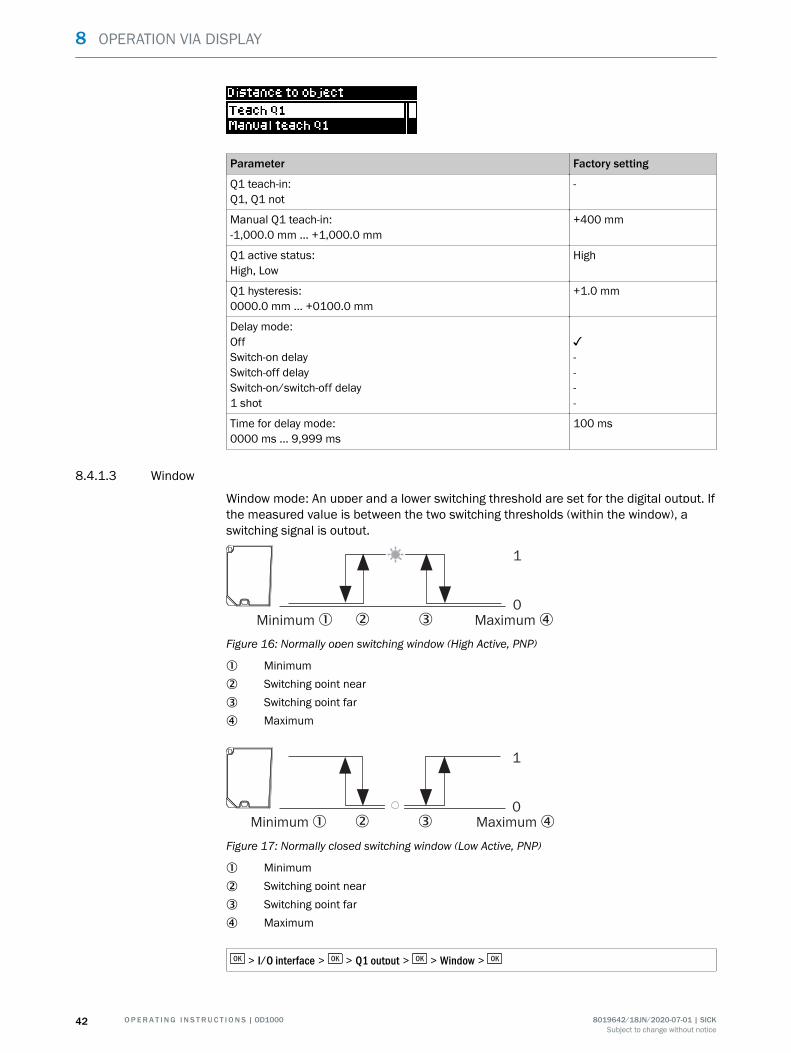
8.4.1.3 Window
Window mode: An upper and a lower switching threshold are set for the digital output. Ifthe measured value is between the two switching thresholds (within the window), aswitching signal is output.
Minimum 1 Maximum 42
1
0
3
Figure 16: Normally open switching window (High Active, PNP)
1 Minimum2 Switching point near3 Switching point far4 Maximum
Minimum 1 Maximum 42
1
0
3
Figure 17: Normally closed switching window (Low Active, PNP)
1 Minimum2 Switching point near3 Switching point far4 Maximum
> I/O interface > > Q1 output > > Window >
8 OPERATION VIA DISPLAY
42 O P E R A T I N G I N S T R U C T I O N S | OD1000 8019642/18JN/2020-07-01 | SICKSubject to change without notice

Parameter Factory settings
Q1 teach-in:Switching point 1, switching point 2
-
Manual Q1 teach-in:Switching point 1: -1,000.0 mm ... +1,000.0 mmSwitching point 2: -1,000.0 mm ... +1,000.0 mm
+400.0 mm-400.0 mm
Q1 active status:High, Low
High
Q1 hysteresis:0000.0 mm ... +0100.0 mm +1.0 mm
Delay mode:OffSwitch-on delaySwitch-off delaySwitch-on/switch-off delay1 shot
✓----
Time for delay mode:0 ms ... 9,999 ms
100 ms
8.4.1.4 ObSB (object between sensor and background)
Object between device and background: In this switching mode, any background can betaught in as a reference. If an object obscures the background or the distance to thebackground changes significantly, this causes the device to switch. This switching modeis primarily suited to the reliable detection of high-gloss or extremely dark materials.This makes it possible to detect even painted vehicle parts with large approach angles,for example.
Minimum 1 Maximum 34
1
0
2
Figure 18: Object between device and background (normally open – High Active, PNP)
1 Minimum2 Tolerance around teach point: ± 4.0 mm3 Maximum4 Switching point (reference background)
OPERATION VIA DISPLAY 8
8019642/18JN/2020-07-01 | SICK O P E R A T I N G I N S T R U C T I O N S | OD1000 43Subject to change without notice

Minimum 1 Maximum 34
1
0
2
Figure 19: Object between device and background (normally closed – Low Active, PNP)
1 Minimum2 Tolerance around switching point: ± 4.0 mm3 Maximum4 Switching point (reference background)
> I/O interface > > Q1 output > > ObSB >
Parameter Factory setting
Q1 teach-in:Q1, Q1 not
-
Manual Q1 teach-in:-1,000.0 mm ... +1,000.0 mm
+400 mm
Q1 active status:High, Low
High
Q1 hysteresis:0000.0 mm ... +0100.0 mm
+1.0 mm
Q1 ObSB tolerance-1,000.0 mm ... +1,000.0 mm
+4.0 mm
Delay mode:Off, switch-on delay, switch-off delay, switch-on/switch-off delay, 1shot
Off
Time for delay mode:0000 ms ... 9,999 ms
100 ms
8.4.1.5 Alarm
The alarm function is only available in the Advanced user level. A constant switching sig‐nal is output at the output of the device while no measurement is possible. This func‐tion can be used to evaluate the measured value at the analog output, for example.
> I/O interface > > Q1 output > > Alarm >
Parameter Factory settings
Alarm Off
8.4.1.6 Signal level warning
The signal level warning function is only available in the Advanced user level.
8 OPERATION VIA DISPLAY
44 O P E R A T I N G I N S T R U C T I O N S | OD1000 8019642/18JN/2020-07-01 | SICKSubject to change without notice

A warning can be output via the Q1 and Q2 digital outputs if the signal level dropsbelow a certain value. This value can either be specified as a number value or deter‐mined by the Teach-in function. When the Teach-in function is used, the threshold valuefor outputting the warning is calculated by reducing the measured signal level value byabout 12%. Then the warning will not be output until the signal level is about 12% lowerthan it was at the time it was taught in.
The level warning threshold or signal level switching point can be set manually using asignal level within the value range of 0 to 5,000. The signal level is a sensor-specific,unitless value. We recommend configuring the setting using application-specific testmeasurements.
In automated mode, the device automatically regulates the reception level to around1,000. In the case of very critical object surfaces, an abrupt loss of signal can thereforeoccur as soon as a readjustment is no longer possible. In settings other than Auto, thereis no automatic adjustment, which makes it easier to define thresholds for the signallevel warning.
> I/O interface > > Q1 output > > Signal level warning >
Parameter Factory settings
Q1 teach-in:Switching point 1, switching point 2
-
Manual Q1 teach-in:-0 ... 5,000
112
Q1 active status:High, Low
High
Q1 hysteresis:0 ... 10,000
10
Delay mode:Off, switch-on delay, switch-off delay, switch-on/switch-off delay, 1shot
Off
Time for delay mode:0000 ms ... 9,999 ms
100 ms
8.4.1.7 Edge height change
The edge height change function is only available in the Advanced user level, see"Device", page 53.
> I/O interface > > Q1 output > > Edge height change >
Parameter Factory settings
Q1 active status:High, Low High
Delay mode:Off, switch-on delay, switch-off delay, switch-on/switch-off delay, 1shot Off
OPERATION VIA DISPLAY 8
8019642/18JN/2020-07-01 | SICK O P E R A T I N G I N S T R U C T I O N S | OD1000 45Subject to change without notice

Parameter Factory settings
Time for delay mode:0000 ms ... 9,999 ms 100 ms
8.4.2 Q2 / Qa output
The Q2 / Qa output can be configured either as an analog output or as a digital output.
8.4.2.1 Notes on the output functions
8.4.2.1.1 4-20 mA output function
If the 4-20 mA setting is selected, output 2 functions as an analog current output. Themeasured value of the device is output as a proportional-linear current value that corre‐sponds to the other device settings.
8.4.2.1.2 0-10 V output function
If the 0 - 10 V setting is selected, output 2 functions as an analog voltage output. Themeasured value of the device is output as a proportional-linear voltage value that corre‐sponds to the other device settings.
8.4.2.1.3 Digital output function
In the case of the digital output function, output 2 functions as a digital output. Sinceoutput 1 is used exclusively for switching, this setting corresponds to the behavior ofoutput 1. A switching signal that corresponds to the other device settings is outputbased on the current measured value.
8.4.2.1.4 Off output function
When the Off output function is activated, output 2 does not have any function and istherefore deactivated.
8.4.2.2 4-20 mA analog output
> I/O interface > > Q2/Qa output > > 4-20 mA analog output >
Parameter Factory setting
Qa teach-in:Distance (4 mA)Distance (20 mA)
--
Manual Qa teach-in:Distance (4 mA): -1,000.0 mm ... +1,000.0 mmDistance (20 mA): -1,000.0 mm ... +1,000.0 mm
-400.0 mm+400.0 mm
8.4.2.3 0-10 V analog output
> I/O interface > > Q2/Qa output > > 0-10 V analog output >
8 OPERATION VIA DISPLAY
46 O P E R A T I N G I N S T R U C T I O N S | OD1000 8019642/18JN/2020-07-01 | SICKSubject to change without notice

Parameter Factory setting
Qa teach-in:Distance (0 V)Distance (10 V)
--
Manual Qa teach-in:Distance (0 V): -1,000.0 mm ... +1,000.0 mmDistance (10 V): -1,000.0 mm ... +1,000.0 mm
-400.0 mm+400.0 mm
8.4.2.4 Digital output
The Q2 digital output provides the following switching modes:• DtO, distance to object (1-point), one switching point• Window, two switching points• ObSB, object between sensor (device) and background, one switching point• Q2 = Q1 not• Alarm (only in Advanced user level)• Signal level warning (only in Advanced user level)• Edge height change (only in Advanced user level)
> I/O interface > > Q2/Qa output > > Digital output >
Parameter Factory setting
Distance to object > Q2 teach-in:Q2, Q2 not
-
Distance to object > manual Q2 teach-in:-1,000.0 mm ... +1,000.0 mm
+400.0 mm
Distance to object > Q2 active status:High, Low
High
Distance to object > Q2 hysteresis:0000.0 mm ... +0100.0 mm
+1.0 mm
Distance to object > delay mode:Off, switch-on delay, switch-off delay, switch-on/switch-off delay, 1shot
Off
Distance to object > time for delay mode:0000 ms ... 9,999 ms
100 ms
Window > Q2 teach-in:Switching point 1, switching point 2
-
Window > manual Q2 teach-in:Switching point 1, switching point 2
-
Window > Q2 active status:High, Low
High
Window > Q2 hysteresis:0000.0 mm ... +0100.0 mm
+1.0 mm
Window > delay mode:Off, switch-on delay, switch-off delay, switch-on/switch-off delay, 1shot
Off
Window > time for delay mode:0000 ms ... 9,999 ms
100 ms
OPERATION VIA DISPLAY 8
8019642/18JN/2020-07-01 | SICK O P E R A T I N G I N S T R U C T I O N S | OD1000 47Subject to change without notice

Parameter Factory setting
ObSB > Q2 teach-in:Q2, Q2 not
-
ObSB > manual Q2 teach-in:-1,000.0 mm ... +1,000.0 mm
+400.0 mm
ObSB > Q2 active status:High, Low
High
ObSB > Q2 hysteresis:0000.0 mm ... +0100.0 mm
+1.0 mm
ObSB > Q2 ObSB tolerance-1,000.0 mm ... +1,000.0 mm
+4.0 mm
ObSB > delay mode:Off, switch-on delay, switch-off delay, switch-on/switch-off delay, 1shot
Off
ObSB > time for delay mode:0000 ms ... 9,999 ms
100 ms
8.4.2.5 Off
When the Off output function is activated, output 2 does not have any function and istherefore deactivated.
8.4.3 In1 input
8.4.3.1 Notes on the input functions
8.4.3.1.1 Description
The In1 input is used for the following tasks:■ Configuration of various device parameters, see "Teach-in", page 50■ Switching the laser on or off at defined times
If the function is set to Teach (factory setting), the specific parameters or different mea‐sured value hold functions can be configured by creating signal levels of differentlengths at pin 5. If the function is set to Laser off, when a signal is created the laser isswitched off for the duration of the created signal.
The In1 input must be active in order to be used accordingly (every setting apart fromOff). The Off setting deactivates the input and, therefore, all functions.
NOTEDeactivating the input is possible only via the display, SOPAS ET, or IO-Link, but not viathe input itself.
The input behavior can be selected as normally open (High Active, factory setting) ornormally closed (Low Active). When Laser off is used, the logic also determines whetherthe creation of a signal at the input causes the laser to switch off (factory setting) or on.
8 OPERATION VIA DISPLAY
48 O P E R A T I N G I N S T R U C T I O N S | OD1000 8019642/18JN/2020-07-01 | SICKSubject to change without notice

8.4.3.1.2 Hold function
The following hold functions are available:• Measured value: Holds the measured value which is present when there is a hold
input signal (rising edge).
ON
OFF
12
HOLD
1 Measured value2 Output hold value (sample hold value)
• Peak value: Holds the largest measured value which is present in the intervalbetween the last falling edge and the hold input signal (next rising edge).
ON
OFF
1
2
3
HOLD
1 Measured value2 Output hold value (peak hold value)3 Interval in which an analysis is carried out.
• Lowest value: Holds the smallest measured value which is present in the intervalbetween the last falling edge and the hold input signal (next rising edge).
ON
OFF
1 2
3 3HOLD
1 Measured value2 Output hold value (bottom hold value)3 Interval in which an analysis is carried out.
• Peak-to-peak value: Holds the differential value between the smallest and thelargest measured value present in the interval between the last falling edge andthe hold input signal (next rising edge).
P(2)
P(1)
B(1)
B(2)
P(1)-B(1)
P(2)-B(2)
ON
OFF
1
3
2
3HOLD
1 Measured value2 Output hold value (peak-to-peak hold value)3 Interval in which an analysis is carried out.
OPERATION VIA DISPLAY 8
8019642/18JN/2020-07-01 | SICK O P E R A T I N G I N S T R U C T I O N S | OD1000 49Subject to change without notice

• Average value: Holds the mathematical average of all measured values present inthe interval between the last falling edge and the hold input signal (next risingedge).
ON
OFF
1
2
3
HOLD
1 Measured value2 Output hold value (average hold value)3 Interval in which an analysis is carried out.
8.4.3.1.3 Teach-in
Description
In the Teach-in operating mode you can use various teach functions by creating signallevels of various lengths at the In1 input.
The timing tolerance for all teach functions is +/- 20 ms.
The following functions are available:
Teach function Time [ms]
Switching off laser 200
Switching on laser 300
Distance to object for Q1: Teach Q 400
Distance to object for Q1: Teach Q not 500
Switching window for Q1: Teach Q near 600
Switching window for Q1: Teach Q far 700
ObSB (Background) for Q1: Teach Q 800
ObSB (Background) for Q1: Teach Q not 900
Switching window for Q1: Centering teach 1000
Distance to object for Q2: Teach Q 1100
Distance to object for Q2: Teach Q not 1200
Switching window for Q2: Teach Q near 1300
Switching window for Q2: Teach Q far 1400
ObSB (Background) for Q2: Teach Q 1500
ObSB (Background) for Q2: Teach Q not 1600
Switching window for Q2: Centering teach 1700
QA with 4-20 mA for Q2: Teach 4 mA 1800
QA with 4-20 mA for Q2: Teach 20 mA 1900
QA with 0-10 V for Q2: Teach 0 V 2000
QA with 0-10 V for Q2: Teach 10 V 2100
QA (4-20 mA or 0-10 V): Centering teach 2200
Switching off teach confirmation 2300
8 OPERATION VIA DISPLAY
50 O P E R A T I N G I N S T R U C T I O N S | OD1000 8019642/18JN/2020-07-01 | SICKSubject to change without notice

Teach function Time [ms]
Switching on teach confirmation 2400
Signal level warning Q1: Teach Q 2500
Signal level warning Q1: Teach Q not 2600
Signal level warning Q2: Teach Q 2700
Signal level warning Q2: Teach Q not 2800
Teaching in the zero point 2900
Laser off > 5,000
1 Centering limits. The near and far points that have been moved via centering must always lie within thevalue range limits. Moved points must always be evaluated by the user.
8.4.3.2 In1 function
Use the In1 function for the following tasks:• Configure various device parameters• Switch the laser on and off at defined times• Activate device functions• Activate and deactivate the debounce function
> I/O interface > > In1 input > > In1 function >
Parameter Factory setting
Teach-in ✓Hold function -
Measured value offset -
Laser off -
Off -
Debouncing
The debounce function is only available in the Advanced user level.
When debouncing is activated, the input signal must be applied constantly to input In1for 30 ms. The timing tolerances of the external teach-in functions take into account anactivation or deactivation of the debounce function. It is not necessary to adjust thetimings.
> I/O interface > > In1 input > > In1 function > > Debouncing>
Parameter Factory setting
Debouncing?:Yes, no Yes
8.4.3.3 In1 active status
The input behavior can be selected as normally open (High Active, factory setting) ornormally closed (Low Active).
OPERATION VIA DISPLAY 8
8019642/18JN/2020-07-01 | SICK O P E R A T I N G I N S T R U C T I O N S | OD1000 51Subject to change without notice

> I/O interface > > In1 input > > In1 active status >
Parameter Factory setting
High, Low High
8.4.3.4 Teach confirmation
If the Teach-in confirmation function is activated, a confirmation can be output via the dig‐ital output Q1 for each teach-in via the In1 input.
max.
1 s
500 ms
In1 input
Hold (last active
Q1 status is held)
Teach-in successful
Teach-in failed
1 2 3 4 5 6 7
Teach-in successful
Teach-in failed
100 ms (OK)
100 ms (OK)
300 ms(error)
300 ms(error)
Figure 20: Teach confirmation
1 Input In12 Hold (last active Q1 status is held)3 Teach-in successful4 Digital output before teach-in
8 OPERATION VIA DISPLAY
52 O P E R A T I N G I N S T R U C T I O N S | OD1000 8019642/18JN/2020-07-01 | SICKSubject to change without notice

5 Teach-in request retains the last active Q1 status in order, for example, to avoid toggling ifhysteresis is too low.
6 Teach-in execution time, max. 1 s7 First signal edge at Q1 after starting the teach-in: Initiate confirmation by inverting for
100 ms.8 Result: OK (100 ms), error (300 ms)9 Quit confirmation after 500 ms.ß Return to current digital output. The digital output can be modified via a new teach-in
point.à Teach-in failedá Error
> I/O interface > > In1 input > > Teach confirmation >
Parameter Factory setting
Yes, no No
8.5 Device
8.5.1 User level
Simple and Advanced user levels are available.
Only certain functions are available depending on the user level set:• Easy: frequently required functions (factory setting)• Advanced: virtually all available functions
Changing the user level only affects operation via the display and via SOPAS ET. Allfunctions are available at all times for operation and configuration via IO-Link.
> Device > > User level >
Parameter Factory setting
Easy, Advanced Easy
8.5.2 Reset
The device can be reset to the factory settings or to saved customer settings (see "Savingcustomer settings", page 54).
NOTEUpon confirmation that the device is to be reset, it carries out a warm start. During thedevice restarting process, the device and its function are temporarily deactivated.
> Device > > Reset > > Factory settings >
OPERATION VIA DISPLAY 8
8019642/18JN/2020-07-01 | SICK O P E R A T I N G I N S T R U C T I O N S | OD1000 53Subject to change without notice

> Device > > Reset > > Customer settings >
Parameter Factory setting
Yes, no -
8.5.3 Saving customer settings
Once settings have been made, they can be saved as customer settings. These settingscan be restored at any time via Reset> Customer settings.
> Device > > Save customer settings >
Parameter Factory setting
No, yes -
8.5.4 Language
The language of the display texts can be set.
> Device > > Language >
Parameter Factory setting
Deutsch/German, Englisch/English Englisch/English
8.5.5 Display settings
Settings can be made for the alignment, brightness, and switch-on/switch-off behaviorof the display.
Description of the parameters for the switch display on/off function:• Auto: The display switches itself off if no buttons are pressed for 3 minutes. The
display switches on again when a button is pressed.• Off: The display switches itself off when the button lock is activated. If the button
lock is not activated, the display switches itself off if no buttons are pressed for 3minutes. The display switches on again when a button is pressed.
• On: The display remains permanently on. This setting is not recommended as itcan reduce the service life of the OLED display.
> Device > > Display settings >
8 OPERATION VIA DISPLAY
54 O P E R A T I N G I N S T R U C T I O N S | OD1000 8019642/18JN/2020-07-01 | SICKSubject to change without notice
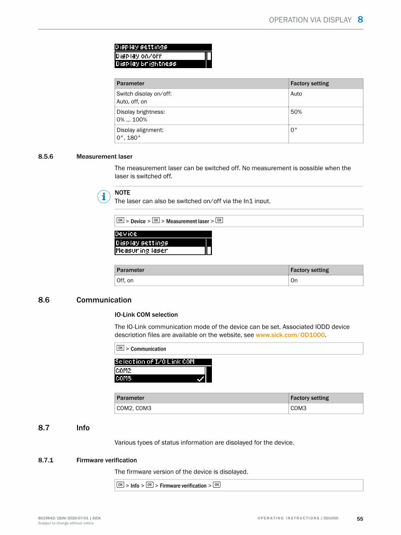
Parameter Factory setting
Switch display on/off:Auto, off, on
Auto
Display brightness:0% ... 100%
50%
Display alignment:0°, 180°
0°
8.5.6 Measurement laser
The measurement laser can be switched off. No measurement is possible when thelaser is switched off.
NOTEThe laser can also be switched on/off via the In1 input.
> Device > > Measurement laser >
Parameter Factory setting
Off, on On
8.6 Communication
IO-Link COM selection
The IO-Link communication mode of the device can be set. Associated IODD devicedescription files are available on the website, see www.sick.com/OD1000.
> Communication
Parameter Factory setting
COM2, COM3 COM3
8.7 Info
Various types of status information are displayed for the device.
8.7.1 Firmware verification
The firmware version of the device is displayed.
> Info > > Firmware verification >
OPERATION VIA DISPLAY 8
8019642/18JN/2020-07-01 | SICK O P E R A T I N G I N S T R U C T I O N S | OD1000 55Subject to change without notice

8.7.2 Serial number
The serial number of the device is displayed.
> Info > > Serial number >
8.7.3 Sensor operating hours
The operating hours of the device are displayed.
> Info > > Sensor operating hours >
8.7.4 Laser operating hours
The operating hours of the laser are displayed.
> Info > > Laser operating hours >
8.7.5 Sensor status
Information about the status of the device is displayed.
The following data can be accessed:• Number of errors: States the number of errors that have occurred• Number of warnings: States the number of active warnings• Error history: Detailed information and history of the most recent errors (max. 10)
> Info > > Sensor status >
Parameter Factory setting
Number of errors, number of warnings, error history -
8.7.6 Part number
The part number of the device is displayed.
> Info > > Part number >
8 OPERATION VIA DISPLAY
56 O P E R A T I N G I N S T R U C T I O N S | OD1000 8019642/18JN/2020-07-01 | SICKSubject to change without notice

OPERATION VIA DISPLAY 8
8019642/18JN/2020-07-01 | SICK O P E R A T I N G I N S T R U C T I O N S | OD1000 57Subject to change without notice

9 Operation via IO-Link
The device can exchange process data and parameters via IO-Link. To do this, it is con‐nected to a suitable IO-Link master.
The IO-Link interface of the device has the following properties:
Table 5: Properties of the IO-Link interface
IO-Link specification V 1.1V 1.0
Minimum cycle time 2.3 ms (COM2)0.46 ms (COM3)
Transmission rate adjustableCOM2 (38.4 kBaud)COM3 (230.4 kBaud)
Process data width 16-bit outgoing (from the device to the master)
Process data type INT (signed integer)
Parameter configuration server function (datastorage)
Yes
9.1 Process data
In the factory settings, the process data telegram displays the distance value measuredby the device in millimeters (16-bit width unsigned).
By configuring the parameters of the device you can change the process data format aswell as resolution and offset for the distance value.
The following process data formats are available:
Table 6: Process data formats
No. Description Comments
1 Distance (16-bit) Factory setting
2 Level (16-bit) -
3 Timer (16-bit) -
4 Edge height change (16-bit) -
5 Distance (14-bit) + Status Q1 + Status Q2 -
6 Level (14-bit) + Status Q1 + Status Q2 -
7 Timer (14-bit) + Status Q1 + Status Q2 -
8 Edge height change (14-bit) + Status Q1 + Status Q2 -
9.2 Device data
In addition to the process data, device data (parameters, identification data, and diag‐nostic information) can be transmitted to and from the device. To use this function, asensor-specific device description file (IODD) is needed in the IO-Link master.
A download package with the IODD and supplementary documentation is available atwww.sick.com/OD1000.
9 OPERATION VIA IO-LINK
58 O P E R A T I N G I N S T R U C T I O N S | OD1000 8019642/18JN/2020-07-01 | SICKSubject to change without notice
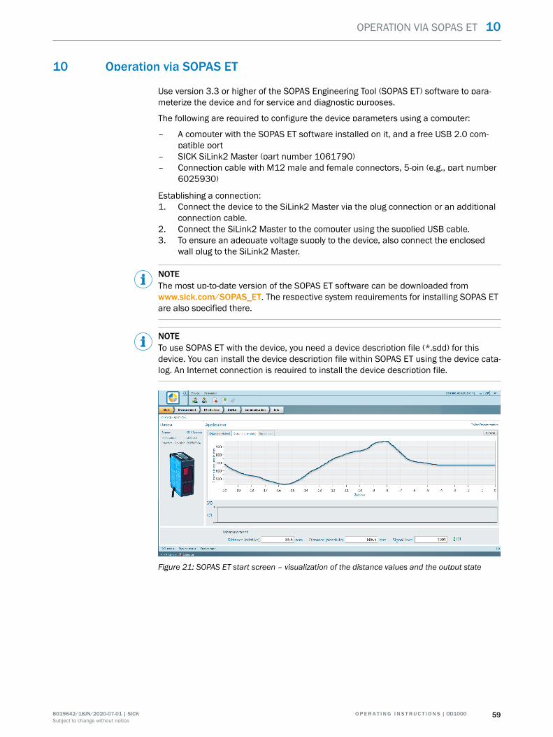
10 Operation via SOPAS ET
Use version 3.3 or higher of the SOPAS Engineering Tool (SOPAS ET) software to para‐meterize the device and for service and diagnostic purposes.
The following are required to configure the device parameters using a computer:
– A computer with the SOPAS ET software installed on it, and a free USB 2.0 com‐patible port
– SICK SiLink2 Master (part number 1061790)– Connection cable with M12 male and female connectors, 5-pin (e.g., part number
6025930)
Establishing a connection:1. Connect the device to the SiLink2 Master via the plug connection or an additional
connection cable.2. Connect the SiLink2 Master to the computer using the supplied USB cable.3. To ensure an adequate voltage supply to the device, also connect the enclosed
wall plug to the SiLink2 Master.
NOTEThe most up-to-date version of the SOPAS ET software can be downloaded fromwww.sick.com/SOPAS_ET. The respective system requirements for installing SOPAS ETare also specified there.
NOTETo use SOPAS ET with the device, you need a device description file (*.sdd) for thisdevice. You can install the device description file within SOPAS ET using the device cata‐log. An Internet connection is required to install the device description file.
Figure 21: SOPAS ET start screen – visualization of the distance values and the output state
OPERATION VIA SOPAS ET 10
8019642/18JN/2020-07-01 | SICK O P E R A T I N G I N S T R U C T I O N S | OD1000 59Subject to change without notice

Figure 22: SOPAS ET function menus – visualization of the light distribution curve on the receiverfor easy setting of the distance range
NOTEThe device immediately applies parameters that have been modified using SOPAS ETand permanently saves them. This does not require calling up a separate function.
As well as visualizing the measured values, all device functions can also be set andchecked in SOPAS ET. SOPAS ET is particularly useful for configuring the distance rangeand edge height change functions, which are only available in the Advanced user level.
10 OPERATION VIA SOPAS ET
60 O P E R A T I N G I N S T R U C T I O N S | OD1000 8019642/18JN/2020-07-01 | SICKSubject to change without notice

11 Maintenance
11.1 Cleaning
NOTICEEquipment damage due to improper cleaning.Improper cleaning may result in equipment damage.
■ Only use recommended cleaning agents and tools.■ Never use sharp objects for cleaning.
b Clean the front screen at regular intervals and in the event of contamination usinga lint-free lens cloth (part no. 4003353) and plastic cleaning agent (part no.5600006). The cleaning interval essentially depends on the ambient conditions.
11.2 Maintenance plan
During operation, the device works maintenance-free.
Depending on the assignment location, the following preventive maintenance tasksmay be required for the device at regular intervals:
Table 7: Maintenance plan
Maintenance work Interval To be carried outby
Check device and connecting cablesfor damage at regular intervals.
Depends on ambient conditions andclimate.
Specialist
Clean housing and viewing window. Depends on ambient conditions andclimate.
Specialist
Check the screw connections andplug connectors.
Depends on the place of use, ambi‐ent conditions or operating require‐ments. Recommended: At least every6 months.
Specialist
MAINTENANCE 11
8019642/18JN/2020-07-01 | SICK O P E R A T I N G I N S T R U C T I O N S | OD1000 61Subject to change without notice

12 Troubleshooting
12.1 General faults, warnings, and errors
Possible faults and corrective actions are described in the table below for troubleshoot‐ing. In the case of faults that cannot be rectified using the information below, pleasecontact SICK Service. To find your agency, see the final page of this document.
NOTEBefore calling, make a note of all type label data such as type code, serial number, etc.,to ensure faster processing.
General faults are subdivided into warnings and errors. Current measured values con‐tinue being output when there are warnings; measurement is no longer possible whenthere are faults.
Question/Problem Possible causes Troubleshooting
The device is not dis‐playing a measure‐ment.
• Laser of the device not acti‐vated
• Laser spot not aimed atobject
• Object outside the measur‐ing range
• Receiver element of thedevice not receiving suffi‐cient light
Advanced application settings• Check whether the laser of the
device is activated.• Check whether the laser spot is
aimed at the object.• Make sure that the object is
within the measuring range of thedevice.
• Check the light distribution curvein SOPAS ET. This function is onlyavailable in the Advanced userlevel. The light distribution curveshows whether the receiver ele‐ment of the device is receivinglight. In this case, the light distrib‐ution curve normally displays amaximum within the area shown.This graphic visualizes the lightreflectance on the receiver ele‐ment.
The display shows awarning triangle in thetop right. Measure‐ment not possible.
• Light path obscured
• Device not in measuringrange
• Specular surfaces
• Make sure that the light path isclear.
• Make sure that the device is inthe measuring range.
• Check the surface characteris‐tics.
12.2 Detecting and displaying errors
In addition to measurement errors (see "Action in case of incorrect measurements",page 38), the device can also detect and display other errors. The errors are outputtedvia the display, SOPAS ET or IO-Link.
Error memory
The device has an error memory where its internal error states are recorded. The lasterror to have occurred is always saved. The content of the error memory is retainedwhen the device is switched off and when the Reset > Factory settings function is used.
12 TROUBLESHOOTING
62 O P E R A T I N G I N S T R U C T I O N S | OD1000 8019642/18JN/2020-07-01 | SICKSubject to change without notice

Possible errors
Table 8: Explanation of the error codes
Error code SOPAS ET hex code /device status
Meaning Troubleshooting
- - / No signal No measurement pos‐sible
• Check the measuringrange.
• Increase the cycle timesetting.
• Decrease the distanceto the object.
If the error cannot be recti‐fied, contact SICK Service.
- - / Laser switched off Laser is deactivated Turn laser on.
Temperatureerror
0x50 / Temperatureerror0x10 / Temperaturewarning
Operating temperatureundershot orexceeded
Check the ambient temper‐ature and raise or lower it ifnecessary.
Laser error 0x11 / Laser warning0x60 / Laser error 10x61 / Laser error 20x62 / Laser error 3
Laser error Contact SICK Service.
Internal error 0x80 / Internal error 10x81 / Internal error 20x82 / Internal error 30x83 / Internal error 4
Operating fault Check the electrical envi‐ronment and improve it, ifnecessary (stability, voltagesupply, EMC influences).If the error cannot be recti‐fied, contact SICK Service.
If a different message is output, contact Sick Service.
12.3 Information for service cases
You should collect and write down the following device information ahead of time if youneed to contact SICK Service:
• Information about the firmware version• Information about the hardware• Information about operating hours
This information can be accessed via SOPASair.
12.4 Returns
b Do not dispatch devices to the SICK Service department without consultation.b The device must be sent in the original packaging or an equivalent padded pack‐
aging.
NOTETo enable efficient processing and allow us to determine the cause quickly, pleaseinclude the following when making a return:
■ Details of the contact person■ Description of the application■ Description of the fault that occurred
TROUBLESHOOTING 12
8019642/18JN/2020-07-01 | SICK O P E R A T I N G I N S T R U C T I O N S | OD1000 63Subject to change without notice
12.5 Repairs
Repair work on the device may only be performed by qualified and authorized person‐nel from SICK AG. Interruptions or modifications to the device by the customer will inval‐idate any warranty claims against SICK AG.
12.6 Disposal
CAUTIONRisk of injury due to hot device surface.The surface of the device can become hot during operation.
■ Before commencing disassembly, switch off the device and allow it to cool downas necessary.
If a device can no longer be used, dispose of it in an environmentally friendly manner inaccordance with the applicable country-specific waste disposal regulations. Do not dis‐pose of the product along with household waste.
NOTICEDanger to the environment due to improper disposal of the device.Disposing of devices improperly may cause damage to the environment.Therefore, observe the following information:
■ Always observe the national regulations on environmental protection.■ Separate the recyclable materials by type and place them in recycling containers.
12 TROUBLESHOOTING
64 O P E R A T I N G I N S T R U C T I O N S | OD1000 8019642/18JN/2020-07-01 | SICKSubject to change without notice

13 Technical data
NOTEThe relevant online data sheet for your product, including technical data, dimensionaldrawing, and connection diagrams can be downloaded, saved, and printed from theInternet:
• www.sick.com/OD1000
Please note: This documentation may contain further technical data.
13.1 Mechanics/electronics
Table 9: Technical data for mechanics/electronics
Supply voltage Uv DC 18 V ... 30 V 1)
Residual ripple ≤ 5 Vss2)
Power consumption ≤ 2.5 W 3)
Warm-up time < 10 min
Housing material Zinc die cast acrylic glass (PMMA), with scratch-proof coating
Connection type 20 cm cable with M12 male connector, 5-pin
Status indicators OLED display, 3 status LEDs
Operating elements 4 pushbuttons
Weight 280 g
Dimensions see "Setup and dimensions", page 14
Enclosure rating IP 65, IP 67
Protection class III in accordance with EN 50178
Electrical safety IEC 61010-1 AMD 1:2016-12UL 61010-1:2012/R:2016-04
1) Limit values, reverse-polarity protected. Operation in short-circuit protected network: max. 8 A.2) Must not fall short of or exceed UV tolerances.3) Without load, at +20 °C.
13.2 Performance
Table 10: Technical data for performance
Measuring range 200 mm ... 1,000 mm 1)
Resolution 50 µm 2)
Repeatability 0.4 mm 2), 3)
Linearity ± 1.5 mm 2), 4)
Response time 1.5 ms 5)
Measuring frequency ≤ 3 kHz
Output time ≥ 0.33 ms
Light sender Laser, visible red lightWavelength: 655 nmMaximum pulse power: 0.78 mWMaximum average power: 0.39 mWMaximum pulse duration: 1.8 ms
Laser class Laser class 1 according to EN/IEC 60825-1:2014. Complies with21 CFR 1040.10 and 1040.11 except for the listed tolerances inthe document “Laser Notice No. 50” of June 24, 2007.
TECHNICAL DATA 13
8019642/18JN/2020-07-01 | SICK O P E R A T I N G I N S T R U C T I O N S | OD1000 65Subject to change without notice

Typical light spot size 1.5 mm x 1.5 mm
Additional function Adjustable averaging or median filter, switching modes: distanceto object (DtO), window or ObSB (object between sensor (device)and background), teachable digital output, invertible digital out‐put, teachable analog output, invertible analog output, switchableanalog output mA/V, multifunctional input: laser off / externalteach-in / deactivated, display switch-off, user interface lock, dis‐play can be rotated by 180°, alarm function, edge height change,time functions (ON/OFF delay, 1-shot)
1) 6% ... 90% reflectance; with standard settings.2) 90% reflectance (white), at constant ambient conditions.3) Statistical error 3 σ.4) Observe min. warm-up time of 10 minutes.5) With measuring frequency of 3 kHz, target change white 90%/white 90%.
Linearity
–3.0(–0.04)
–2.0(–0.08)
–1.0(–0.12)
0.0
1.0(0.04)
2.0(0.08)
3.0(0.12)
200(7.87)
300(11.81)
400(15.75)
500(19.69)
600(23.62)
700(27.56)
800(31.50)
900(35.43)
1000(39.37)
Typical linearity deviation in mm (inch)
Distance in mm (inch)
White 90 % remission
1 Black 6 % remission
2
Stainless steel3
21
3
Figure 23: Linearity diagram
1 Typical linearity deviation in mm (inch)2 Black, 6% remission3 White, 90% remission4 Stainless steel5 Distance in mm (inch)
13.3 Interfaces
Table 11: Technical data for interfaces
Analog output 1x 4 mA ... 20 mA (< 600 W) / 1 x 0 V … 10 V (> 20 kW)Resolution: 16-bit
digital output 2 x push-pull 1), IO-Link
13 TECHNICAL DATA
66 O P E R A T I N G I N S T R U C T I O N S | OD1000 8019642/18JN/2020-07-01 | SICKSubject to change without notice

Multifunctional input (In1input)
1 x 2)
IO-Link Function: Process data, configuration, diagnostics, data storageData transmission rate: 230.4 kBit/s (COM3) / 38.4 kBit/s(COM2)Protocol: V 1.1 / V 1.0
1) PNP: HIGH = UV - (< 3 V) / LOW = < 3 V; NPN: HIGH = < 3 V / LOW = UV.2) Can be used as laser off, external teach-in, or deactivated.
13.4 Ambient data
Table 12: Ambient data
Ambient operating temperature –10 °C … +50 °C 1)
Storage temperature –20 °C … +60 °C
Temperature drift 0.15 mm/K
Typ. ambient light immunity Artificial light: ≤ 3,000 lx 2)
Sunlight: ≤ 10,000 lx
Vibration resistance EN 60068-2-6 / EN 60068-2-64
Shock resistance EN 60068-2-27
1) At UV = 24 V.2) With constant object movement in the measuring range.
TECHNICAL DATA 13
8019642/18JN/2020-07-01 | SICK O P E R A T I N G I N S T R U C T I O N S | OD1000 67Subject to change without notice

14 Accessories
NOTEAccessories and where applicable mounting information can be found online at:
• www.sick.com/OD1000
14 ACCESSORIES
68 O P E R A T I N G I N S T R U C T I O N S | OD1000 8019642/18JN/2020-07-01 | SICKSubject to change without notice

15 Annex
15.1 EU declaration of conformity / Certificates
The EU declaration of conformity and other certificates can be downloaded from theInternet at:
• www.sick.com/OD1000
15.2 Licenses
SICK uses open source software which is published by the rights holders under a freelicense. Among others, the following license types are used: GNU General PublicLicense (GPL version 2, GPL version 3), GNU Lesser General Public License (LGPL), MITlicense, zlib license and licenses derived from the BSD license.
This program is provided for general use without warranty of any kind. This warranty dis‐claimer also extends to the implicit assurance of marketability or suitability of the pro‐gram for a particular purpose.
More details can be found in the GNU General Public License. View the completelicense texts here: www.sick.com/licensetexts. Printed copies of the license texts arealso available on request.
ANNEX 15
8019642/18JN/2020-07-01 | SICK O P E R A T I N G I N S T R U C T I O N S | OD1000 69Subject to change without notice

Detailed addresses and further locations at www.sick.com
Australia Phone +61 (3) 9457 0600 1800 33 48 02 – tollfree E-Mail [email protected] Phone +43 (0) 2236 62288-0 E-Mail [email protected]/Luxembourg Phone +32 (0) 2 466 55 66 E-Mail [email protected] Phone +55 11 3215-4900 E-Mail [email protected] Phone +1 905.771.1444 E-Mail [email protected] Republic Phone +420 234 719 500 E-Mail [email protected] Phone +56 (2) 2274 7430 E-Mail [email protected] Phone +86 20 2882 3600 E-Mail [email protected] Phone +45 45 82 64 00 E-Mail [email protected] Phone +358-9-25 15 800 E-Mail [email protected] Phone +33 1 64 62 35 00 E-Mail [email protected] Phone +49 (0) 2 11 53 010 E-Mail [email protected] Phone +30 210 6825100 E-Mail [email protected] Kong Phone +852 2153 6300 E-Mail [email protected]
Hungary Phone +36 1 371 2680 E-Mail [email protected] Phone +91-22-6119 8900 E-Mail [email protected] Phone +972 97110 11 E-Mail [email protected] Phone +39 02 27 43 41 E-Mail [email protected] Phone +81 3 5309 2112 E-Mail [email protected] Phone +603-8080 7425 E-Mail [email protected] Phone +52 (472) 748 9451 E-Mail [email protected] Phone +31 (0) 30 229 25 44 E-Mail [email protected] Zealand Phone +64 9 415 0459 0800 222 278 – tollfree E-Mail [email protected] Phone +47 67 81 50 00 E-Mail [email protected] Phone +48 22 539 41 00 E-Mail [email protected] Phone +40 356-17 11 20 E-Mail [email protected] Phone +7 495 283 09 90 E-Mail [email protected] Phone +65 6744 3732 E-Mail [email protected]
Slovakia Phone +421 482 901 201 E-Mail [email protected] Phone +386 591 78849 E-Mail [email protected] Africa Phone +27 10 060 0550 E-Mail [email protected] Korea Phone +82 2 786 6321/4 E-Mail [email protected] Spain Phone +34 93 480 31 00 E-Mail [email protected] Phone +46 10 110 10 00 E-Mail [email protected] Phone +41 41 619 29 39 E-Mail [email protected] Phone +886-2-2375-6288 E-Mail [email protected] Phone +66 2 645 0009 E-Mail [email protected] Phone +90 (216) 528 50 00 E-Mail [email protected] Arab Emirates Phone +971 (0) 4 88 65 878 E-Mail [email protected] Kingdom Phone +44 (0)17278 31121 E-Mail [email protected] Phone +1 800.325.7425 E-Mail [email protected] Phone +65 6744 3732 E-Mail [email protected]
SICK AG | Waldkirch | Germany | www.sick.com
8019
642/
18JN
/202
0-07
-01/
en