
Operating Instructions ROTANTA 46 S ROTANTA 46 ... - … Rotanta 46 S Benchtop... · 1 1 Intended...
51
Operating Instructions ROTANTA 46 S ROTANTA 46 RS ROTANTA 46 RSC Please enter the following details: Stock no. ................................................... Monitoring no. ................................................... Location .................................................... This operating instruction has to be used for the centrifuges bearing the following Manufacturing Nos. : (the Manufacturing No. of a centrifuge can be see from its name plate) Type of centrifuge Voltage Article No. Manufacturing No. ROTANTA 46 S 208-240 V 4806 XXXX-01-00 ROTANTA 46 S 110-127 V 4806-01 XXXX-02-00 ROTANTA 46 RS 220-240 V 4811 XXXX-01-00 ROTANTA 46 RS 110-127 V 4811-01 XXXX-01-00 ROTANTA 46 RS 208-240 V 4811-07 XXXX-01-00 ROTANTA 46 RS 220-240 V 4811-50 XXXX-01-00 ROTANTA 46 RS 110-127 V 4811-51 XXXX-01-00 ROTANTA 46 RSC 220-240 V 4813 XXXX-01-00 ROTANTA 46 RSC 110-127 V 4813-01 XXXX-01-00 ROTANTA 46 RSC 208-240 V 4813-07 XXXX-01-00 ROTANTA 46 RSC 220-240 V 4813-50 XXXX-01-00 ROTANTA 46 RSC 110-127 V 4813-51 XXXX-01-00 © 02.02 A. Hettich, D-78532 Tuttlingen Order no. AB079-01GB
Transcript of Operating Instructions ROTANTA 46 S ROTANTA 46 ... - … Rotanta 46 S Benchtop... · 1 1 Intended...

Operating Instructions
ROTANTA 46 S ROTANTA 46 RS
ROTANTA 46 RSC
Please enter the following details:
Stock no. ...................................................
Monitoring no. ...................................................
Location
....................................................
This operating instruction has to be used for the centrifuges bearing the following Manufacturing Nos. : (the Manufacturing No. of a centrifuge can be see from its name plate)
Type of centrifuge Voltage Article No. Manufacturing No.
ROTANTA 46 S 208-240 V 4806 XXXX-01-00 ROTANTA 46 S 110-127 V 4806-01 XXXX-02-00
ROTANTA 46 RS 220-240 V 4811 XXXX-01-00 ROTANTA 46 RS 110-127 V 4811-01 XXXX-01-00 ROTANTA 46 RS 208-240 V 4811-07 XXXX-01-00 ROTANTA 46 RS 220-240 V 4811-50 XXXX-01-00 ROTANTA 46 RS 110-127 V 4811-51 XXXX-01-00
ROTANTA 46 RSC 220-240 V 4813 XXXX-01-00 ROTANTA 46 RSC 110-127 V 4813-01 XXXX-01-00 ROTANTA 46 RSC 208-240 V 4813-07 XXXX-01-00 ROTANTA 46 RSC 220-240 V 4813-50 XXXX-01-00 ROTANTA 46 RSC 110-127 V 4813-51 XXXX-01-00
© 02.02 A. Hettich, D-78532 Tuttlingen Order no. AB079-01GB

Certificate of EU - Conformity
as defined by the EU regulations
− for machines 89/392/EWG − for electro-magnetic compatibility 89/336/EWG, amended by regulations
91/263/EWG, 92/31/EWG and 93/68/EWG − for low voltage 73/23/EWG, amended by regulation 93/68/EWG
We, Messrs. Andreas Hettich Gartenstraße 100 D-78532 Tuttlingen,
hereby certify that centrifuge model(s) ROTANTA 46S, ROTANTA 46 RS, ROTANTA 46 RSC is (are) manufactured in accordance with the following standards and regulations:
EN 61010 part 1 and 2 EN 55011
in addition the following national standards and regulations are applied: VBG 1 DIN 58970 VBG 4 BS 4402 VBG 7z VBG 20
Tuttlingen 11.06.2007 Hettich Zentrifugen
ppa. H. Eberle

I
Contents
1 Intended application ..................................................................................................1
2 Notes on safety .........................................................................................................1
3 Warning symbols......................................................................................................3
4 Delivery checklist .....................................................................................................3
5 Manufacturer’s address............................................................................................3
6 Technical specifications ...........................................................................................4
7 Diagrams of operating conditions.............................................................................6
8 Initial operation.........................................................................................................7
9 Installing the rotor and fitting attachments................................................................8
10 Control and display elements ...............................................................................9 10.1 Control elements ...............................................................................................9 10.2 Status display..................................................................................................10 10.3 Data fields .......................................................................................................10
10.3.1 Data field 1...............................................................................................10 10.3.2 Data field 2...............................................................................................10 10.3.3 Data field 3...............................................................................................10 10.3.4 Data field 4...............................................................................................10 10.3.5 Data field 5...............................................................................................10
11 Entering centrifuging data...................................................................................11 11.1 Data field 1......................................................................................................11 11.2 Data field 2......................................................................................................12 11.3 Data field 3......................................................................................................12
11.3.1 Run up with preset level from 1 - 9 ..........................................................12 11.3.2 Run up with preset time, adjustable in the predefined time range............13 11.3.3 Run down with preset level from R0-R9...................................................13 11.3.4 Run down with preset time, adjustable in the predefined time range.......13 11.3.5 Run down with brake release...................................................................14
11.4 Data field 4......................................................................................................14 11.5 Data field 5......................................................................................................15 11.6 Programming notes.........................................................................................15
11.6.1 Retrieving a program: ..............................................................................16 11.6.2 Modifying a program and storing it under the same number....................16 11.6.3 Modifying and then starting a program.....................................................16
12 Making changes while the centrifuge is running .................................................16
13 Calculating RCF or RPM ....................................................................................16 13.1 RCF.................................................................................................................16 13.2 RPM ................................................................................................................17
14 How to gain rapid access when switching on .....................................................17

II
14.1 Centrifuging program after switching on ......................................................... 17
15 Acoustic signal ................................................................................................... 18
16 Retrieving the number of operating hours .......................................................... 18
17 Time / date retrieval............................................................................................ 18
18 Sedimentation effect........................................................................................... 18
19 Centrifuging........................................................................................................ 19 19.1 - with the speed RPM parameter .................................................................... 19 19.2 - with the RCF parameter................................................................................ 19 19.3 - with a program.............................................................................................. 20 19.4 - with temperature preselection (cooled centrifuge) ........................................ 20 19.5 - of denser substances ................................................................................... 20
20 EMERGENCY STOP ......................................................................................... 21
21 Changing the rotor.............................................................................................. 21
22 Rotor identification.............................................................................................. 21
23 Emergency release ............................................................................................ 22
24 Care / maintenance ............................................................................................ 22 24.1 Supporting lugs............................................................................................... 22
25 Faults ................................................................................................................. 23 25.1 Note on faults.................................................................................................. 23 25.2 Fault table ....................................................................................................... 23
26 Repairs............................................................................................................... 24
27 Customer Services / Servicing ........................................................................... 24
28 Acceptance of the centrifuges for repair............................................................. 24
29 Appendix ............................................................................................................ 25 29.1 Option: Key-operated switch.......................................................................... 25 29.2 Option: Programs being run in sequence ...................................................... 25
29.2.1 Program sequence with simultaneous keying-in of program data ........... 25 29.2.2 Entering a sequence of previously stored programs................................ 26 29.2.3 Retrieving a program sequence............................................................... 27 29.2.4 Running a program sequence ................................................................. 27 29.2.5 Changing a program sequence ............................................................... 27 29.2.6 Deleting a program sequence.................................................................. 27
30 Rotors and accessories...................................................................................... 28
31 S e r v i c e ........................................................................................................ 1

1
1 Intended application The centrifuge is used for separating substances or mixtures with a density of up to max. 1.2 kg/dm³. Through the production of centrifugal force it can separate mixtures or alter the proportions in a mixture. If the substance or mixture to be centrifuged is denser than 1.2 kg/dm³, the rated speed should be reduced (see section “Centrifuging of denser substances”). 2 Notes on safety
• This centrifuge is a state-of-the-art piece of equipment which is extremely safe to
operate. − However, it can lead to danger for users or others if used by untrained staff, in an
inappropriate way or for a purpose other than that it was designed for. • Before the initial operation of your centrifuge you should read and pay attention to the
operating instructions. • Along with the operating instructions and the legal regulations on accident prevention,
you should also follow the recognised professional regulations for working in a safe and professional manner. These operating instructions should be read in conjunction with any other instructions concerning accident prevention and environmental protection based on the national regulations of the country where the device is to be used.
• The centrifuge should be installed on a good, stable base. • When setting the equipment up you should pay attention to the following points:
− A 300 mm safety zone must be established around the centrifuge in accordance with IEC 1010-2-2.
− This safety zone must be kept clear of both people and hazardous substances at all times when the centrifuge is in operation.
− According to the laboratory instrument standards EN 61010-2-20 an emergency switch to separate power supply in the event of a failure must be installed in the building electrical system. This switch has to be placed remote from the centrifuge, prefered outside of the room in which the centrifuge is installed or near by the exit of this room.
• Do not place any object in front of the ventiduct. − Keep a ventilation area of 300 mm around the ventiduct.
• The centrifuge should always be loaded evenly. • Centrifuge containers must not be filled beyond the capacity specified by the
manufacturer. − Centrifuge containers should only be filled outside the centrifuge.
• Standard centrifuge containers of glass will not stand RCF values exceeding 4000 (DIN 58970, pg. 2)
• No attachments should be used other than those authorised by the manufacturer. • Centrifuge containers may only be centrifuged with accessories (reducing adapters,
frames, suspensions, etc.) authorised by the manufacturer (see section "Rotors and accessories).
• The centrifuge may only be operated when the balance is within the bounds of acceptability.

2
• The centrifuge must not be operated in areas subject to danger of explosions. • The centrifuge must not be used with:
− inflammable or explosive materials − materials that react with one another producing a lot of energy.
• If users have to centrifuge hazardous materials or compounds contaminated with toxic, radioactive or pathogenic micro-organisms, they must take appropriate measures. Without additional proceedings (like an additional bioseal between bucket and lid of bucket or angle rotor with a special bioseal between rotor and lid) a centrifuge is not a biosafety system in accordance to the regulation EN 61010-2-20. In the case of material belonging to risk group II (see the World Health Organisation’s “Laboratory Biosafety Manual”) they should employ a biosafety system. Under this system small drips and aerosols are prevented from escaping by a bioseal (packing ring) located between the hanger and the lid. Centrifuge containers with special screw caps, as obtainable through trade suppliers, can also be used for hazardous substances. In the case of materials from the higher risk groups greater safety provision is required than the arrangements described above. In a biosafety system, centrifuge containers with special screw caps must be used.
• For further details of available biosafety systems see section “Rotors and accessories”. If in doubt, you should obtain relevant information from the manufacturer.
• The centrifuge must not be operated with highly corrosive substances which could impair the mechanical integrity of rotors, hangers and accessories.
• Any rotors, hangers or accessories showing clear signs of corrosion or mechanical defects must not be used for centrifuging.
• In order to prevent corrosion developing through cleaning or disinfectant agents, it is most important that any specific instructions from the manufacturers of such agents should be followed carefully. Before applying any cleaning or disinfecting procedure other than those recommended by the manufacturer, the user should contact the manufacturer to make sure that the planned process will not damage the equipment.
• Only original spare parts and authorised original accessories may be used. • In case of fault or emergency release, never touch the rotor before it has stopped
turning. • This centrifuge is classified in Germany as a Group 3 device according to the
Medizinische Geräteverordnung MedGV (the regulations on medical equipment). • It conforms to safety regulations based on:
IEC 1010-1/-2 DIN - EN61010 Parts 1and 2
• The safe operation and reliability of the centrifuge can only be guaranteed if: − the centrifuge is operated in accordance with the operating instructions, − repairs are carried out by engineers approved by the manufacturer, − the electrical installation on the site where the centrifuge is installed conforms to the
demands of IEC stipulations, − prescribed tests to UVV-VBG7z are carried out by an expert.
• With centrifuges for robotic use please pay attention to the notes of the key operated switch.
No claim under guarantee will be considered by the manufacturer unless the above instructions have been adhered to.

3
3 Warning symbols
Caution! Follow instructions carefully.
Load centrifuge rotor evenly. All positions on rotor must be filled.
Do not fill centrifuge containers inside the centrifuge.
4 Delivery checklist The following items and accessories are delivered with the centrifuge:
1 Connecting cable 230 V 1 Fuse T 2 AL; 250 V 1 Square spanner 1 Release pin 1 Lubricating grease for supporting lugs 1 Operating instructions 1 Rotor instructions ROTANTA 46 S
1 Notes on moving the equipment safely ROTANTA 46 RS and ROTANTA 46 RSC
1 Notes on moving the equipment safely ROTANTA 46 RSC 1 One opend-end wrench SW 17 The rotor(s) and associated accessories are included in the delivery in the quantity ordered. 5 Manufacturer’s address Hettich Zentrifugen GmbH & Co. KG Gartenstraße 100 D-78532 Tuttlingen Germany Telephone ## 49 7461 705-0, Fax ## 49 7461 705-125 e-mail [email protected] http:\\www.HettichLab.com

4
6 Technical specifications
Manufacturer
Hettich Zentrifugen D-78532 Tuttlingen
Model ROTANTA 46 S ROTANTA 46 RS Product no. 4806 4806-01 4811,
4811-50 4811-01, 4811-51
Mains voltage (± 10%) 208-240 V 1∼ 110-120 V 1∼ 220-240 V 1∼ 110-127 V 1∼Mains frequency 50 - 60 Hz 50 - 60 Hz 50 Hz 60 Hz Connected load 1400 VA 1200 VA 1800 VA 2000 VA Current consumption 6.5 A 11 A 9 A 17 A Power consumption 1030 W 950 W 1500 W 1650 W Refrigerant ----- R 404A Max. capacity 4 x 750 ml Max. density 1.2 kg/dm3 Speed RPM 7500 Force RCF 10310 Kinetic energy 50000 Nm Obligatory inspection yes Environment − Ambient temperature 5°C up to 40°C − Relative humidity max. 80% up to 31°C,
descending in a linear pattern down to 50% at 40°C
Sample overtemp. ≤ 15 K ----- Class of protection Ι EMC ISM (Industrial Science Medicine) − Emission
(Radio interference suppression)
EN 55011 Class B
FCC Class B
EN 55011 Class B
FCC Class B
− Immunity according to EN 50082-2 Noise level (dependent on rotor) ≤70 dB(A) ≤70 dB(A)
Dimensions • Width 580 mm 815 mm • Depth 690 mm 690 mm • Height 410 mm 410 mm Weight approx. 65 kg 95 kg

5
Manufacturer
Hettich Zentrifugen D-78532 Tuttlingen
Model ROTANTA 46 RS ROTANTA 46 RSC
Product no. 4811-07 4813, 4813-50
4813-01, 4813-51 4813-07
Mains voltage (± 10%) 208-240 V 1∼ 220-240 V 1∼ 110-127 V 1∼ 208-240 V 1∼Mains frequency 60 Hz 50 Hz 60 Hz 60 Hz Connected load 2000 VA 1800 VA 2000 VA 2000 VA Current consumption 10 A 9 A 17 A 10 A Power consumption 1750 W 1500 W 1650 W 1750 W Refrigerant R 404A Max. capacity 4 x 750 ml Max. density 1.2 kg/dm3 Speed RPM 7500 Force RCF 10310 Kinetic energy 50000 Nm Obligatory inspection yes Environment − Ambient temperature 5°C to 40°C − Relative humidity max. 80% up to 31°C,
descending in a linear pattern down to 50% at 40°C
Sample overtemp. ≤ 15 K Class of protection Ι EMC ISM (Industrial Science Medicine) − Emission
(Radio interference suppression)
FCC Class B
EN 55011 Class B
FCC Class B
− Immunity according to EN 50082-2 Noise level (dependent on rotor) ≤70 dB(A)
Dimensions • Width 815 mm 815 mm • Depth 690 mm 690 mm • Height 410 mm 635 mm Weight approx. 95 kg 110 kg

6
7 Diagrams of operating conditions Diagram 1
Diagram 2
Diagram 3
Diagram 4
Diagram 5
Diagram 6

7
8 Initial operation • According to the laboratory instrument standards EN 61010-2-20 an emergency
switch to separate power supply in the event of a failure must be installed in the building electrical system. This switch has to be placed remote from the centrifuge, prefered outside of the room in which the centrifuge is installed or near by the exit of this room.
• The amount of space required is given under dimensions in the “Technical specifications” section.
• The centrifuge should be set up in a suitable position on a good, firm surface. When setting up the equipment, care should be taken to provide the required safety area of 300 mm around the centrifuge in accordance with IEC 1010-2-2.
The safety area must be clear of all persons and hazardous substances at all times when the centrifuge is in operation.
• Do not place any object in front of the ventiduct. − Keep a ventilation area of 300 mm around the ventiduct.
• You should check that the mains voltage corresponds to that stipulated on the model plate.
• Using the connecting cable provided, the centrifuge should be connected to a standard mains socket.
• Mains switch “ON” - switch position “I”. The following information will be displayed on the screen:
1. Centrifuge type. 2. The rated speed “n-max-Rotor” acquired most recently through rotor
identification. 3. The version number corresponding to the model. 4. The entry field containing centrifuge data as used in the last run or entered as
parameters. • If the symbol is displayed in the top left-hand corner, this means that the lid is
locked. Rotate the turning handle on the front panel to the left. The symbol will change to .
• Open the lid.
The lid can only be opened when the centrifuge is switched on and the rotor is at rest. If it cannot be opened under these circumstances, see the section on “Emergency release”.
• Remove the transport safety device (see instruction sheet on “Moving the equipment safely.”).

8
9 Installing the rotor and fitting attachments See Rotor Instructions B032 or the section “Changing the rotor”. • All spaces must be filled on rotors with free-swinging hangers. No empty rotor
positions are permitted. • Always fill the centrifuge containers outside the centrifuge. • Check by eye that each container is filled to the same level. • Loads must be equal between opposing positions.
For details of allowable combinations see the section "Rotors and accessories" in the appendix.
• Close the lid. Turn the handle on the front panel to the right. The symbol must be visible.
The centrifuge can only be started when the symbol is visible.

9
10 Control and display elements
10.1 Control elements
Key for selecting the parameters. Press key until the numerical field above the selected parameter is displayed in reverse (dark background).
Data can only be entered into an reverse numerical field. An reverse numerical field will be cleared automatically after 10 secs.
Selector key
Adjusting knob
For setting the key data in the numerical field.
START.
Start centrifuging. The rotation light will come on in the display.
STOP.
Stop centrifuging. The run-down will be performed in a manner laid down in advance. If braking level 1-9 has been set, the rotor decelerate with braking level 9 ( the shortest run-down time). If braking level 0 has been set, the rotor does not decelerate with braking level 9 but with a reduced braking force.

10
10.2 Status display
Lid locked. Start centrifuge or open lid. symbol flashing, centrifuging finished
Lid not locked. Centrifuge can not be started. Lid can be opened or locked.
Rotation light is on from the moment the start command is issued until the rotor comes to rest.
STOP After a timed switch-off or after . key pressed. After an EMERGENCY STOP the display light flashes.
LOCK 1, LOCK 2
Switch setting of the key-operated switch (only with centrifuges with key-operated switch).
10.3 Data fields 10.3.1 Data field 1
- adjustable: • Switch-on time • Operating time • Centrifuging time • Long run
Query the effect of sedimentation (see the section "Sedimentation effect")
10.3.2 Data field 2
- adjustable: • Operating speed RPM • Relative centrifugal force RCF
10.3.3 Data field 3
- adjustable: • Run-up using different levels - with a preset time • Run-down using different levels - with a preset time • Free run-down • Run-down with brake switched off
10.3.4 Data field 4
- adjustable: • Radius for determining the RPM or RCF • Temperature (in cooled centrifuges)
10.3.5 Data field 5
- adjustable: Program number Keys for − input STO
. − output RCL
.

11
11 Entering centrifuging data Before each entry: 1. Use the selector key to select the reverse numerical field above the parameter.
Press the selector key as many times as necessary to bring the required parameter onto the screen with an reverse numerical field.
2. Adjust the number using the adjusting knob in the reverse numerical field. 3. Enter all the parameters following the above steps. An reverse numerical field will be cleared automatically after 10 secs. Data set once and used the last time the centrifuge ran always reappear when the rotor is stationary. 11.1 Data field 1 Time Parameter t / min : sec Input 999 : 59 Numerical field t / min : or t / : sec → selectable using key . Adjustable times: Connect time tconn = Run-up time tup + centrifuging time tcent tconn : is the time from when the . key is pressed until the expiry
of the time in numerical field t / min : sec. The connect time tconn must always be longer than the run-up time tup . If connect time tconn is less than run-up time tup the device will cut out during the run-up time. The set speed is not attained.
Operating time toper = Run-up time tup + centrifuging time tcent + run-down time tdown or
toper = Connect time tconn + run-down time tdown toper : is the time from pressing the . key until the rotor comes to
rest. Centrifuging time tcent = Connect time tconn - Run-up time tup tcent : is the time without run-up time tup and without run-down
time tdown . Long run ---:-- Set the parameter t / min : → using the key .
Using the adjusting knob, select the message " 00 " in the reverse numerical field.
Set the parameter t / : sec → using the key . Using the adjusting knob, select the message "- - -" in the reverse numerical field. When the long run parameter is set, connection time is displayed once the centrifuge has started. A long run can only be stopped by pressing the . key.

12
Sedimentation effect
parameter → can be selected with the key. The numerical value corresponds to the area of the squares of speed and operating time. The numerical value can only be retrieved (see the section "Sedimentation effect").
11.2 Data field 2 Speed Parameter RPM → select using the . key. Enter in increments of 10.
Lowest allowable speed 50 RPM. Any speed (operating speed) can be set between 50 and n-max-Rotor (rated speed). n-max-Rotor can be retrieved using the . key. Press the . key repeatedly until the n-max-Rotor parameter appears on the screen. Hold the . key down. n-max-Rotor is the last speed detected by the rotor identification sensor and is exactly the same as the speed rating displayed on the rotor. This speed cannot and must not be exceeded.
Relative centrifugal force (g-value)
Parameter RCF → select using the . key. Enter in increments of 1. Only an RCF value can be entered here, corresponding to the speed in the numerical field RPM and to the radius in the numerical field r / mm in data field 4 (see section on calculating RCF or RPM).
11.3 Data field 3 Run up, run down and brake cut-out
Profile symbol parameter → can be selected with key or . The selected run-up and run-down modes can be seen at any time from the symbol above the PROFILE parameter. Run-up level 1-9 or run-up time t . Run-down level 0-9 or run-down time t. The run up or run down can be selected within a specific time range. This time range is determined by n-max-Rotor. It varies according to the speed setting.
11.3.1 Run up with preset level from 1 - 9
1-9 1 = long run up 9 = short run up
The maximum run up (level 9) cannot be shortened. It can only be extended up to level 1. The level required should be set with the adjusting knob after selecting the reverse numerical field above the parameter 1-9. The time corresponding to the set level can be seen after the parameter has been selected in the numerical field.
13
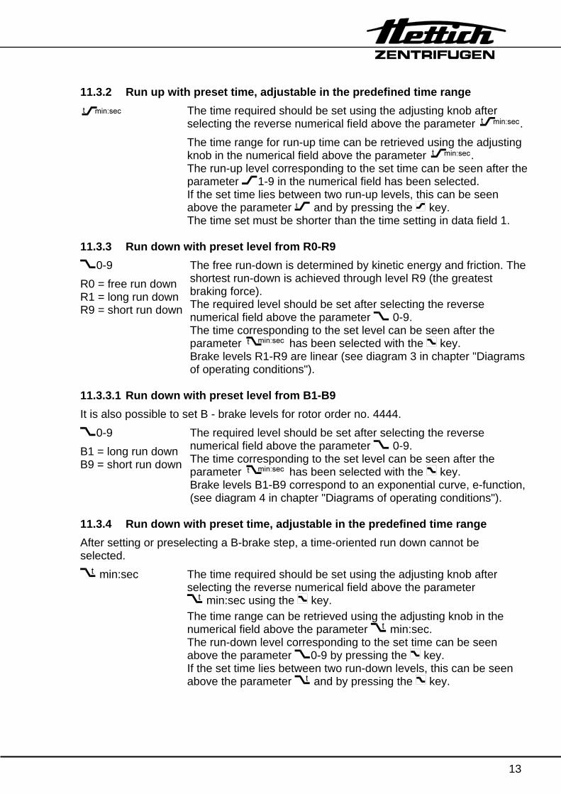
11.3.2 Run up with preset time, adjustable in the predefined time range
The time required should be set using the adjusting knob after selecting the reverse numerical field above the parameter . The time range for run-up time can be retrieved using the adjusting knob in the numerical field above the parameter . The run-up level corresponding to the set time can be seen after the parameter 1-9 in the numerical field has been selected. If the set time lies between two run-up levels, this can be seen above the parameter .
t and by pressing the key. The time set must be shorter than the time setting in data field 1.
11.3.3 Run down with preset level from R0-R9
0-9 R0 = free run down R1 = long run down R9 = short run down
The free run-down is determined by kinetic energy and friction. The shortest run-down is achieved through level R9 (the greatest braking force). The required level should be set after selecting the reverse numerical field above the parameter 0-9. The time corresponding to the set level can be seen after the parameter has been selected with the key. Brake levels R1-R9 are linear (see diagram 3 in chapter "Diagrams of operating conditions").
11.3.3.1 Run down with preset level from B1-B9 It is also possible to set B - brake levels for rotor order no. 4444.
0-9 B1 = long run down B9 = short run down
The required level should be set after selecting the reverse numerical field above the parameter 0-9. The time corresponding to the set level can be seen after the parameter has been selected with the key. Brake levels B1-B9 correspond to an exponential curve, e-function, (see diagram 4 in chapter "Diagrams of operating conditions").
11.3.4 Run down with preset time, adjustable in the predefined time range After setting or preselecting a B-brake step, a time-oriented run down cannot be selected.
.
t min:sec The time required should be set using the adjusting knob after selecting the reverse numerical field above the parameter
.
t min:sec using the key. The time range can be retrieved using the adjusting knob in the numerical field above the parameter .
t min:sec. The run-down level corresponding to the set time can be seen above the parameter 0-9 by pressing the key. If the set time lies between two run-down levels, this can be seen above the parameter .
t and by pressing the key.

14
11.3.5 Run down with brake release A time-oriented run down cannot be selected after setting or preselecting a rotational speed for brake cutoff. If a time-oriented run down has already been selected, it functions until the set rotational speed is reached. n(0) RPM The required speed should be set after selecting the reverse
numerical field above the n(0) RPM parameter with the key. The brake-release speed must be lower than the operational speed RPM stored in data field 2. Once the period of time stored in data field 1 has expired, run down commences at the pre-selected level or time until the set speed is reached. Once this speed is reached, the brake is released and the run-down continues without any further braking until the rotor comes to rest.
11.4 Data field 4 Temperature Parameter T / °C → can be selected with key . .
adjustable from -20° to +40°C. The lowest attainable temperature is reached after 1 hour of
running time, see the “Rotor and accessories” table in the appendix.It is possible to attain lower temperatures by reducing the rotational speed. Such values must be established empirically. First select the reverse numerical field above the T / °C parameter and then set the required temperature using the adjusting knob. The lid should next be locked because cooling cannot take place while the symbol is displayed. Once the . key has been pressed, the ACTUAL temperature is displayed. If the difference between SET and ACTUAL temperatures is greater than 5°C the display will flash. Once a temperature 2 °C below the SET temperature has been reached the cooling system is switched off; it is switched back on again only when the SET temperature is reached. This pattern continues until the lid is unlocked.
Radius Parameter r / mm → can be selected with key . . Smallest radius that can be set = 10 mm. Radius values are shown
in the table “Rotor and accessories” in the appendix. First select the reverse numerical field above the r / mm parameter and then set the required radius using the adjusting knob. A radius value must be entered in order to determine
1. the RCF, 2. RPM.
For further details see section "Calculating RCF or RPM".

15
11.5 Data field 5 Programming Parameter PROG no → can be selected with the PROG
. key. Storage locations 1 - 89 available Storage locations 1 - 99 retrievable Storage location 0 used internally. Data can, however, be
modified. First select the reverse numerical field above the parameter
PROG no., then set storage locations 1-89. Press the STO
. key. The key data entered and selected on the screen will be stored under the current program no. alternatively, press the RCL
. key. The key data stored under the current program no. will be shown on the screen.
11.6 Programming notes When the reverse numerical field above the parameter PROG no. flashes on and off, this signifies:
Number flashing in field → Storage location occupied “- - - -” flashing in field → Temporary storage location occupied
Programs cannot be deleted, they can only be overwritten. When “- - - -” is displayed above the parameter PROG no. and the . key is pressed, the key data displayed will be stored. This key data is stored until a change is made. When a change is made by pressing the . key, the contents of the memory locations are relocated or shifted.
The data from temporary storage location “- - - -” is now in storage location 90, and the modified data is in temporary storage location “- - - -”.
This relocation is repeated for each change until storage location 99 is reached, after which the data is lost, e.g. centrifuging at 500 RPM
Change
Description 1 2 3 - 9 10 11
RPM entry in numerical field 500 600 700 800 - 1400 1500 1600Press . key X X X X - X X X Temporary storage location “- - - -“ 500 600 700 800 - 1400 1500 1600Storage location 90 500 600 700 - 1300 1400 1500Storage location 91 500 600 - 1200 1300 1400Storage location 92 500 - 1100 1200 1300 “ - - - - - - - - Storage location 98 - 500 600 700 Storage location 99 - 500 600
Storage locations 1-99 can only be retrieved when the rotor is stationary.

16
11.6.1 Retrieving a program:
1. Select the reverse numerical field above parameter PROG no. 2. Set the program no. 3. Press the RCL
. key.
11.6.2 Modifying a program and storing it under the same number 1. Retrieve the program as per section “Retrieving a program”. 2. Make the required changes. 3. Select program no. again using the PROG
. key (reverse display). 4. Program no. will flash. Press the STO
. key twice. The modified program is now stored.
11.6.3 Modifying and then starting a program 1. Retrieve program as per section “Retrieving a program”. 2. Make the required changes. 3. Press the . key. Pressing the . key will clear the program no. It is replaced by the display “- - - -”. The modified program is now in the temporary storage location “- - - -” and will reappear on the screen when the rotor stops turning. 12 Making changes while the centrifuge is running Select the appropriate parameter while the centrifuge is running. The numerical value must be displayed inverted. Change the number, then press the . key. Every change must be confirmed by pressing the . key. It is not possible to make any changes during the run-down phase. When a program is altered, the program no. is cleared when the rotor stops turning. The modified data is stored in location “- - - -“ . The program must be retrieved again. 13 Calculating RCF or RPM The calculation can only be performed when RPM is in a range between 50 and n-max-Rotor. See section on "Data field 2" . For each calculation the radius must be entered in mm. The radius is the distance from the centre of the rotor axle to the bottom of the centrifuge container or to the point in the centrifugal product furthest from the axle (DIN 58970, Part 1). The radius measurement can be found from the table “Rotor and accessories” in the appendix. 13.1 RCF Input: 1.Rotational speed see “Data field 2” section 2.Radius see “Data field 4” section When radius is entered, the RCF is updated simultaneously on the screen with the RCF light flashing at the same time.

17
Input: 1.Radius 2.Rotational speed When speed is entered, the RCF is updated simultaneously but not displayed on the screen. The RCF can be retrieved using the . key, during which process the radius light will flash. 13.2 RPM Input: 1.Radius 2.RCF When the RCF is entered, the speed RPM is updated simultaneously but not displayed on the screen; the radius light flashes at the same time. The speed RPM can be retrieved using the key .. Input: 1.RCF 2.Radius When radius is entered, the RCF is updated simultaneously on the screen with the RCF light flashing at the same time. 14 How to gain rapid access when switching on The following procedure will allow the input screen to displayed more quickly:
• Switch mains ON, • Immediately after the first visual change on the screen (an reverse display),
simply press any selector key.
14.1 Centrifuging program after switching on After switching on, the screen displays data from program 1 or from the last program to run. This can be set initially as follows:
1. Lid unlocked, symbol . 2. Mains switch ON.
After the first visual change on the screen (a reverse display), 3. Press the . key; this will produce the following message on the screen:
PROGRAM 1 LAST PROGRAM
4. Select the required option using the adjusting knob. 5. Press the . button; this will produce the message *** OK ***.

18
15 Acoustic signal Options: OFF Signal off. ON 1 Signal at 30 sec. interval when rotor is stationary. ON 2 as ON1, but also when any key is pressed. Setting: • With lid lock off, hold down the key for 8 secs.
• After 8 secs. SOUND/BELL ON1 is displayed inverted. • Choose the required setting with the adjusting knob. • Confirm the setting by pressing the . key. • *** OK *** should now appear on the screen.
16 Retrieving the number of operating hours When the lid is not locked, symbol ,press key and hold it down for 8 secs. Once the message SOUND/BELL ON 1 has appeared on the screen, press the key again. You should see:
CONTROL: XX h ( X = operating hours) 17 Time / date retrieval As when retrieving the number of operating hours, press the key again. The following will appear on the screen:
DATE and TIME These can be set using the . key and the adjusting knob. Use the . key to confirm a change. 18 Sedimentation effect
The alteration of speed with the integral ∫ n2 dt must be taken into account when as-certaining the effect of sedimentation during the centrifuge run-up and run-down time. This integral is evaluated using an integrator. The numerical value above the parameter ∫RCF corresponds to the cross-hatched area of the square formed by speed and operating time. This number can only be retrieved. Changing the time or speed will also have the effect of changing this value.

19
19 Centrifuging 19.1 - with the speed RPM parameter • Enter numerical values:
− Time t / min : sec
− Speed RPM (less than or equal to n-max-Rotor)
− Run-up level / run-up time 1-9 or .
t Run-up time is less than time in t / min : sec
− Run-down ramp / run-down time 0-9 or .
t
− Temperature in cooled centrifuge T / ° C
• Press the . key. • Once the time has expired or the . key has been pressed, the drive switches off. • The centrifuge will run down at the selected braking level or run-down time. • After the rotor has stopped, the message " OPEN OEFFNEN " will appear in
the display. • Open the lid.
Further user operation is only possible after opening the lid once. 19.2 - with the RCF parameter • Enter numerical values
− Time t / min : sec
− Run-up level / run-up time 1-9 or .
t Run-up time is shorter than time in t / min : sec
− Run-down ramp / run-down time 0-9 or .
t
− Radius r / mm For numerical value see table “Rotors and accessories”.
− RCF RCF
− Temperature in cooled centrifuge T / ° C
• Press the . key. • Once the time has expired or the . key has been pressed, the drive switches off. • The centrifuge will run down at the selected braking level or run-down time. • After the rotor has stopped, the message " OPEN OEFFNEN " will appear in
the display. • Open the lid.
Further user operation is only possible after opening the lid once.

20
19.3 - with a program • Select program no. on the screen: PROG-No XX • Press the RCL
. key. • Press the . key. • Once the time has expired or the . key has been pressed, the drive switches off. • The centrifuge will run down at the selected braking level or run-down time. • After the rotor has stopped, the message " OPEN OEFFNEN " will appear in
the display. • Open the lid.
Further user operation is only possible after opening the lid once. 19.4 - with temperature preselection (cooled centrifuge) Temperature can be set through a range from - 20 ° to + 40 ° C. For the lowest temperature achievable by the rotor, attained after 1 hour of run time, see the table “Rotor and accessories”. Temperature behaviour
• If the rotor is stationary and the lid is locked, cooling is in progress. • If the rotor is stationary and the lid is unlocked, cooling is not in progress. 19.5 - of denser substances The rotors are designed to centrifuge substances up to a maximum mean homogenous density of 1.2 kg/dm3 when rotating at the stated speed. Denser substances must be centrifuged at lower speed. The permissible speed can be calculated using the following formula:
Reduced speed (n ) = 1.2Greater density
x Rated speedred
e.g.: RPM 4000, density 1.6 kg/dm3
n = 1.21.6
x 4000 = 3464 RPMred
If in doubt you should obtain clarification from the manufacturer.

21
20 EMERGENCY STOP • Press
.
key twice. • If a braking level R1-R9 or B1-B9 or a run-down time has been set, the rotor
decelerates with braking level R9 (shortest run-down time). • If braking level R0 has been set, the rotor does not decelerates with braking level R9
but with a reduced braking force. • After the rotor has stopped, the message " OPEN OEFFNEN " will appear in
the display. • Open the lid.
Further user operation is only possible after opening the lid once. 21 Changing the rotor • Open the lid. • Loosen the rotor tensioning nut by turning it counter-clockwise with the appropriate
spanner (see delivery checklist) until the release point is reached. Once this point is passed, the rotor frees itself from the motor-shaft cone. Continue turning the nut until the rotor can be lifted off the motor shaft.
• Clean the motor shaft and then lightly grease. • Place the new rotor vertically on the motor shaft. The motor-shaft carrier pin must be
located in the groove on the rotor. • Tighten the tensioning nut. • Check that the rotor is seated securely. 22 Rotor identification • Each time a centrifuging run is started, the centrifuge recognises the rotor code of the
installed rotor with the help of a sensor. This means that the nominal speed of the installed rotor cannot be exceeded.
• After the identification of a newly installed rotor the drive will cut off and its speed rating will be displayed.
• Afterwards the message " OPEN OEFFNEN " will appear in the display. • Open the lid.
Further user operation is only possible after opening the lid once. • If the speed rating of the newly installed rotor is lower than the last speed entered,
the speed rating of the newly installed rotor will be displayed. If the speed rating of the newly installed rotor is higher than the last speed entered, the last speed entered will be displayed.
• Close the lid and press the . key. • Any speed up to the rated speed of the rotor can be entered while the centrifuge is
running.

22
23 Emergency release If loss of current or a centrifuge fault occurs while the centrifuge is running, the lid remains locked.
To release in an emergency, unplug the centrifuge from the mains. Wait for the rotor to stop turning before opening the lid.
Insert the release pin (see delivery checklist) horizontally into the drill hole right in the middle of the front panel. Insert the release pin up to the point at which the turning knob can be rotated to the left when the pin is pushed downwards. Open the lid. 24 Care / maintenance
Before applying any cleaning or disinfecting procedure other than those recommended by the manufacturer, the user should contact the manufacturer to make sure that the planned process will not damage the equipment.
• The centrifuge should be cleaned regularly for reasons of hygiene, and if necessary should also be cleaned with soap or a mild cleaning agent.
• Any adherent impurities should be removed as they can cause corrosion. • Humidity in the air or centrifuge containers with no hermetic seal can lead to
condensation. The centrifuge chamber should therefore be cleaned regularly with a cloth or similar.
• For instructions on how to clean the rotor and accessories see the rotor instructions B032.
• In the case of glass breakage, the fragments of glass along with any spilt centrifuge product should be removed carefully from the centrifuge chamber, the containers or container drill holes.
After a glass breakage the rubber inserts for the containers must be replaced because any residual glass fragments in these inserts can cause further glass breakage.
• If any infectious material should find its way into the centrifuge chamber it should be disinfected immediately.
• When a biosafety system is in use (see section “Rotors and accessories”), the bioseal (packing ring) between the hangers and the lid must be checked and cleaned regularly. This routine should be performed at least once a week. The packing ring should be replaced as soon as any signs of tears, brittleness or wear are shown.
24.1 Supporting lugs The supporting lugs on the rotor must always be well lubricated (use Hettich lubricating grease no. 4051). Only when the supporting lugs are lubricated can it be guaranteed that the hangers will swing out evenly and that the centrifuge will not cut out during operation.

23
25 Faults 25.1 Note on faults • If any fault or defect should arise, this is indicated by a symbol on the screen, while at
the same time an acoustic signal is emitted at 3 sec. intervals. • The drive cuts out. Depending on the error message the run-down is either with or
without braking. After the rotor has come to rest, clearance for opening the lid is issued.
MAINS RESET: - Mains switch OFF for longer than 10 secs. - Mains switch ON. If the fault cannot be rectifield by following the troubleshooting guide and if the error message reappears after performing a MAINS RESET, you should contact Customer Services. 25.2 Fault table
Message / fault Cause Remedy No display --- − No voltage.
− Overvoltage protection tripped out.
− Check supply voltage. − Mains switch ON.
TACHO - ERROR 01 − Faulty speedometer. − Open lid. − Turn rotor manually.
02 − No rotor installed. − Defective motor,
frequency converter or drive.
− MAINS-RESET (see section of notes on faults), when power is switched on, rotor should turn.
IMBALANCE --- Imbalance about motor axis through weight differential in rotor assembly.
− Open lid. − Correct imbalance.
CONTROL - ERROR 04, 06 - 09
Error in lid locking or lid closure.
− Open lid. − MAINS-RESET, (see
N > MAX 05 Rotation too fast section of notes on N < MIN 13 Rotation too slow faults). ROTORCODE 10 Incorrect rotor coding MAINS INTERRUPT --- Power failure, centrifuging
not completed − Open lid. − Push . button.
VERSIONS-ERROR 12 Mismatch between electronic components
− Open lid. − MAINS-RESET, (see
SER I/O - ERROR 30 - 38 Error / defective interface faults). ° C * - ERROR 50 - 56 Error / defective cooling LOCK - ERROR 57 Error / defective program
locking
FU / CCI - ERROR 60 - 83 Error / defective motor control
CONTROL-ERROR 90 – 9597 – 99
Error / defective control unit section of notes on
N > ROTOR-MAX 96 Nominal speed higher than permitted rotor speed
Check the set speed Reduce the set speed

24
26 Repairs
Repairs must only be carried out by personnel authorised to do so by the manufacturer.
27 Customer Services / Servicing Should your centrifuge break down or develop a fault, it should not be touched by anyone except an engineer authorised by the manufacturers. In such a case you should contact Hettich Customer Services. Before contacting our Customer Services department you should make a note of the following: 1. Centrifuge model 2. The factory number Both of these numbers can be found on the centrifuge’s model plate.
Note down any problems experienced.
You must follow the steps above in order to return to normal operation as quickly as possible. 28 Acceptance of the centrifuges for repair If the centrifuge is returned to the manufacturer for repair, it must be decontaminated and cleaned to protect persons, environment and material. We reserve the right to accept contaminated centrifuges. Costs incurred for cleaning and disinfection are to be charged to the customer. We ask for your understanding in this matter.

25
29 Appendix 29.1 Option: Key-operated switch In order to safeguard against deletion of stored programs and/or the unintentional execution of programs, the key-operated switch can be used to select program locking. To choose the required mode of program locking the key must first be inserted in the key-operated switch and the required setting selected on the screen by turning the key to the corresponding position. A change in the program can only be made in keyswitch position 3. The key-operated switch has the following three positions:
Position 1: Display → LOCK 1 setting Previously entered programs can be called up and run but not
modified. Position 2: Display → LOCK 2 setting Only the designated program can be run.
The designated program can not be modified. Position 3: Display → no display No program locking.
29.2 Option: Programs being run in sequence
The optional running of programs in a sequence can only be executed after a change or modification to the program control. Contact the manufacturer or the relevant Hettich service department. With the optional running of programs in a sequence, centrifugation sequences can be performed with different parameters, e.g. different speeds, in a particular order.
A number of programs can be executed in sequence by:
− The program sequence is keyed in, with the individual program data being keyed in at the same time.
− The program sequence of programs which have already been stored is keyed in.
Programs can only be linked if the run-up and the run-down are preselected at stages 1-9 or 0-9. Storing is not possible if startup is time-managed 29.2.1 Program sequence with simultaneous keying-in of program data
1. Call up the parameters in the display, and key in the desired centrifuging data. Parameters and must be set to a stage from 1-9 or 0-9.
2. Select the PR-Part parameter using the PROG. key.
3. Use the adjusting knob in the reversed numerical panel to select the desired program sequence number for starting of program sequences.

26
4. Press the STO. key.
− If program sequence number for starting of program sequences is flashing, STO
. key must be pressed once more. − After the STO
. key is pressed, the program sequence number increases by 1 and is displayed as follows: " + X + ".
− Storing is not possible, if a numerical panel appears in reverse in the display. 5. Enter further data required for centrifuging and repeat step 4. 6. To stop the program sequences the desired run-down stage and/or the brake
force cut-off speed should be verified by the parameter and the PROG. key is
to be pressed. The program sequence no. decrements by 1. The end of the program sequence is indicated by " + X ".
29.2.2 Entering a sequence of previously stored programs Before a program sequence is keyed in, a range must be stipulated which is outside the programs already stored, for example:
− Desired program sequence with the programs: 1 - 3 - 4 - 5 - 8 − Range for the program sequence which has already
been stored: 10 + 11 + 12 + 13 + 14
1. Determine the number of programs in the program sequence. 2. Select in the display the first program for the starting of program sequences,
and press the RCL. key.
3. Use the PROG. key to select the PR-Part parameter, and set the adjusting knob to
a number outside the programs which have already been stored (see above). 4. Press the STO
. key. − If program sequence number for starting of program sequences is flashing,
STO. key must be pressed once more.
− After the STO. key is pressed, the program sequence number increases by 1
and is displayed as follows: " + X + ". 5. Press the RCL
. key. For this purpose the numerical panel must appear in reverse.
6. Use the adjusting knob to select the next program to be stored in the sequence of programs, and again press the RCL
. key. The centrifuging data of the program selected will then appear in the display.
7. Repeat steps 4 - 6. 8. To stop the program sequences the desired run-down stage and/or the brake
force cut-off speed should be verified by the parameter and the PROG. key is
to be pressed. The program sequence no. goes back by 1. The end of the program sequence is indicated by " + X ".
Combinations of sections 29.2.1 and 29.2.2 are possible.

27
29.2.3 Retrieving a program sequence A program sequence can be retrieved as follows: • Select the numerical panel above the PROG-Nr or PR-Part parameter until the
display appears in reverse. • The individual programs in the sequence are retrieved using the adjusting knob.
Start of program sequence: " X + " Duration of program sequence: " .... + X + .... + X +.... " End of program sequence: " + X ".
29.2.4 Running a program sequence A program sequence can be run as follows: • Select the PR-Part parameter, and set adjusting knob to program sequence
No. “ X + “. • Press the RCL
. key. • Press the . key.
When a program which is being run is started up, the program sequence number “ X + “ must appear in the display, but may not appear in reverse.
29.2.5 Changing a program sequence From program version 2.007 it is possible to make changes to a program sequence. When changing a program the link in the program sequence is deleted. The remaining programs are retained in the memory. After any changes the program must be re-linked (see Chapter 29.2.2). e.g. change of numerical values in program sequence no. +12+
program sequence position +12+ corresponds to PROG-No. 4 (see example in Chapter 29.2.2). 1. Using the PROG
. key call up inverse number field via PROG-No or PR-PART. 2. Using the knob select program sequence no."+12+". 3. Press the RCL
. key. 4. Change required numerical values.
This change deletes the link. 5. Press the STO
. key. Replace the link for program sequence 10 - 14 in accordance with Chapter 29.2.2 (Point 2 to Point 8):
The change has no effect on PROG-No. 4. This data is retained. 29.2.6 Deleting a program sequence A program sequence can be deleted as follows: • Select the parameter PR-Part, then use the adjusting knob to set program sequence
no. to " X + " . • Press the STO
. key twice. • Press the PROG
. key.

28
30 Rotors and accessories Order no. 4444 4414 4412
+ Frame
5263+0787 5263+6319 5262 5249 5261 5343 5242 5248
Tubes
Swing out rotor 4-times
Capacity ml 250 250 100 100 50 50 25 15
Dimensions ∅ x L mm 65 x 115 61 x 130 44 x 100 40 x 115 34 x 100 34 x 100 24 x 100 17 x 100
Number p. Frame 1 1 1/2 1/2 6 2/4 5/10 12/24
Number p. Rotor 4 4 8 8 24 16 40 96
RPM RPM 4500 4500 4500 4500 4500 4500 4500 4500
RCF 4211 4392 4256 4256 4279 4302 4302 4302
Radius mm 186 194 188 188 189 190 190 190
Run-up time (97%) sec 60 60 60 60 60 60 60 60
sec 70 70 70 70 70 70 70 70 Run-down time sec 1260 1260 1260 1260 1260 1260 1260 1260
Temperature °C 1) + 6 + 6 + 6 + 6 + 6 + 6 + 6 + 6
Order no. 4444 4414 4412
+ Frame
5247 5227 5257 5281 5266 5258 5265 5247
Tubes
Swing out rotor 4-times
Sarstedt
Capacity ml 7 6 1,5/2,0 1,5/2,0 25 9-12 5 4,5-5
Dimensions ∅ x L mm 12 x 100 12 x 82 Reaction tubes
Reaction tubes 25 x 92 16,5 x 92 16,5 x 57 16,5 x 92
Number p. Frame 20 / 40 20 / 40 40 / 80 16 / 32 5 / 10 11 / 22 11 / 22 20 / 40
Number p. Rotor 160 160 320 128 40 88 88 160
RPM RPM 4500 4500 4500 4500 4500 4500 4500 4500
RCF 4302 4302 4324 3260-4369 4079 4302 4302 4415
Radius mm 190 190 191 144 / 193 180 190 190 195
Run-up time (97%) sec 60 60 60 60 60 60 60 60
sec 70 70 70 70 70 70 70 70 Run-down time sec 1260 1260 1260 1260 1260 1260 1260 1260
Temperature °C 1) + 6 + 6 + 6 + 6 + 6 + 6 + 6 + 6
braked slow-down (9) 1) The lowest possible temperature during the highest unbraked slow-down (0) revolutions and 1 hour running time (only in a cooled centrifuge)

29
Order no. 4444 4414 4412
+ Frame
5264 5227 5280
Tubes
Swing out rotor 4-times
Sarstedt
Capacity ml 3,2-6 2-4
Dimensions ∅ x L mm 15,3 x 75 11,5 x 66
Number p. Frame 12 / 24 20 / 40
Number p. Rotor 96 160
RPM RPM 4500 4500
RCF 4324 4324
Radius mm 191 191
Run-up time (97%) sec 60 60
sec 70 70 Run-down time sec 1260 1260
Temperature °C 1) + 6 + 6
Order no. 4444 4414 4412 5280
+ + 1662
1663 1664 1665 1666 1667 1668
Swing out rotor 4-times
Filter cards 1675 1675 1675 1675 1675 1675
Capacity ml 1 2 4 8 3,2 4 x 1
Dimensions ∅ / A mm2 6,2 / 30 8,7 / 60 12,4 / 120 17,5 / 240 8,7 / 60 6,2 / 30
Number p. Frame 4 4 4 4 4 4
Number p. Rotor 16 16 16 16 16 16
RPM RPM 4500 4500 4500 4500 4500 4500
RCF 2988/4211 2988/4211 2988/4211 2988/4211 2988/4211 2988/4211
Radius mm 132 / 186 132 / 186 132 / 186 132 / 186 132 / 186 132 / 186
Run-up time (97%) sec 60 60 60 60 60 60
sec 70 70 70 70 70 70 Run-down time sec 1260 1260 1260 1260 1260 1260
Temperature °C 1) + 6 + 6 + 6 + 6 + 6 + 6
braked slow-down (9) 1) The lowest possible temperature during the highest unbraked slow-down (0) revolutions and 1 hour running time (only in a cooled centrifuge)

30
Order no. 4444 4414 4412 5280
+ + 1670
2)
1663 1664 1665 1666 1667 1668
Swing out rotor 4-times
Filter cards 1692 1692 1692 1692 1692 1692
Capacity ml 1 2 4 8 3 x 2 4 x 1
Dimensions ∅ / A mm2 6,2 / 30 8,7 / 60 12,4 / 120 17,5 / 240 8,7 / 60 6,2 / 3
Number p. Frame 8 8 8 8 8 8
Number p. Rotor 32 32 32 32 32 32
RPM RPM 4500 4500 4500 4500 4500 4500
RCF 2988/4211 2988/4211 2988/4211 2988/4211 2988/4211 2988/4211
Radius mm 132 / 186 132 / 186 132 / 186 132 / 186 132 / 186 132 / 186
Run-up time (97%) sec 60 60 60 60 60 60
sec 132 132 132 132 132 132 Run-down time sec 186 186 186 186 186 186
Temperature °C 1) + 6 + 6 + 6 + 6 + 6 + 6
Order no. 4444 4414 4412
+ Frame
5269 5259 6306 4459 5248 5264 6301 5268
Tubes
Swing out rotor 4-times
Falcon Vacutainer
Capacity ml 50 50 15 15 12 8 7 5
Dimensions ∅ x L mm 29 x 115 29 x 115 17 x 120 17 x 120 16 x 100 16 x 75 12 x 100 13 x 100
Number p. Frame 6 2 / 4 7 / 14 13 12 / 24 12 / 24 12 / 24 12 / 24
Number p. Rotor 24 16 56 52 96 96 96 96
RPM RPM 4500 4500 4500 4500 4500 4500 4500 4500
RCF 4460 4392 4460 4460 4302 4324 4302 4369
Radius mm 197 194 197 197 190 191 190 193
Run-up time (97%) sec 60 60 60 60 60 60 60 60
sec 70 70 70 70 70 70 70 70 Run-down time sec 1260 1260 1260 1260 1260 1260 1260 1260
Temperature °C 1) + 6 + 6 + 6 + 6 + 6 + 6 + 6 + 6
braked slow-down (9) 1) The lowest possible temperature during the highest unbraked slow-down (0) revolutions and 1 hour running time (only in a cooled centrifuge)
2) Object carrier will not stand RCF values exceeding 1100

31
Order no. 4444 4414 4412 4455 4413
+ + Frame
5267 4456 / 4451
4457 / 4453 4454 5127 /
4443 0526 / 4442
0528 / 4458
Tubes
Swing out rotor 4-times
Corning
Capacity ml 2 750 450 250 250 100 100
Dimensions ∅ x L mm 10 x 52 97 x 136 70 x 159 60 x 172 62 x 135 44 x 100 58 x 160
Number p. Frame 20 / 40 1 1 1 1 2 1
Number p. Rotor 160 4 4 4 4 8 4
RPM RPM 4500 4500 4500 4500 4500 4500 4500
RCF 4279 4596 4754 4754 4573 4120 4618
Radius mm 203 203 210 210 202 182 204
Run-up time (97%) sec 73 73 73 73 73 73 73
sec 71 71 71 71 71 71 71 Run-down time sec 1630 1630 1630 1630 1630 1630 1630
Temperature °C 1) + 6 + 3 + 3 + 3 + 3 + 3 + 3
Order no. 4444 4455 4413
+ Bottle,Glas / Reduction
4441 0521 / 4439
0519 / 4439 4437 0507 /
4436 4435 4434 0578 / 4433
Tubes
Swing out rotor 4-times
Falcon Falcon Vacutainer Sarstedt
Capacity ml 50 50 25 15 15 5 - 7 4 - 10 2,7 – 7
Dimensions ∅ x L mm 29 x 115 34 x 100 24 x 100 17 x 120 17 x 100 13 x 100 16,5 x 92 11,5 x 92
Number p. Frame 5 4 7 12 19 21 19 30
Number p. Rotor 20 16 28 48 76 84 76 120
RPM RPM 4500 4500 4500 4500 4500 4500 4500 4500
RCF 4460 4166 4211 4460 3917 4211 4256 4211
Radius mm 197 184 186 197 173 186 188 186
Run-up time (97%) sec 73 73 73 73 73 73 73 73
sec 71 71 71 71 71 71 71 71 Run-down time sec 1630 1630 1630 1630 1630 1630 1630 1630
Temperature °C 1) + 3 + 3 + 3 + 3 + 3 + 3 + 3 + 3
braked slow-down (9) 1) The lowest possible temperature during the highest unbraked slow-down (0) revolutions and 1 hour running time (only in a cooled centrifuge)

32
Order no. 4444 4454 4413 4428
+ Bottle / Reduction Frame
0278 / 4432
Blood Bag system 3- and 4-times
Blood Bag system
1-and 2-times4452
4429 4429 4431 4427
Swing out rotor 4-times
Microtiter-
plates
Micronic- system
Culture plates
Culture bottle
Capacity ml 1,5 – 2,2 500 500
Dimensions ∅ x L mm Reaction tubes
Number p. Frame 42 1 1 4 1 2 2
Number p. Rotor 168 4 4 16 4 8 8
RPM RPM 4500 4500 4500 4500 4500 4500 4500
RCF 3147/4234 4750 4686 3849 3849 3736 3803
Radius mm 139 / 187 210 207 170 170 165 168
Run-up time (97%) sec 73 73 73 75 75 75 75
sec 71 71 71 72 72 72 72 Run-down time sec 1630 1630 1630 1338 1338 1338 1338
Temperature °C 1) + 3 + 3 + 3 + 6 + 6 + 6 + 6
Order no. 4446 5095 5091
+ Frame
5262 5249 5243 5242 5248 5247 5227 5257
Tubes
Swing out rotor
6-times
Reaction tubes
Capacity ml 100 100 50 25 15 7 6 1,5/2,0
Dimensions ∅ x L mm 44 x 100 40 x 115 34 x 100 24 x 100 17 x 100 12 x 100 12 x 82
Number p. Frame 1 1 2 5 12 20 20 40
Number p. Rotor 6 6
RPM RPM 4000 4000 4000 4000 4000 4000 4000 4000
RCF 3291 3291 3291 3309 3309 3309 3327 2504/3381
Radius mm 184 184 185 185 185 185 186 140/189
Run-up time (97%) sec 44 44 44 44 44 44 44 44
sec 56 56 56 56 56 56 56 56 Run-down time sec 435 435 435 435 435 435 435 435
Temperature °C 1) - 2 - 2 - 2 - 2 - 2 - 2 - 2 - 2
braked slow-down (9) 1) The lowest possible temperature during the highest unbraked slow-down (0) revolutions and 1 hour running time (only in a cooled centrifuge)

33
Order no. 5095 5091
+ Frame
5281 5266 5258 5265 5247 5264 5227
Tubes
Swing out rotor 6-times
Reaktion tubes Sarstedt
Capacity ml 1,5/2,0 25 9 – 12 5 4,5 – 5 3,2 – 6 2 – 4
Dimensions ∅ x L mm 25 x 92 16,5 x 92 16,5 x 57 11,5 x 92 15,3 x 75 11,5 x 66
Number p. Frame 16 5 11 11 20 12 20
Number p. Rotor 96 30 66 66 120 72 120
RPM RPM 4000 4000 4000 4000 4000 4000 4000
RCF 3148 3309 3309 3417 3309 3327 3327
Radius mm 176 185 185 191 185 186 186
Run-up time (97%) sec 44 44 44 44 44 44 44
sec 56 56 56 56 56 56 56 Run-down time sec 435 435 435 435 435 435 435
Temperature °C 1) - 2 - 2 - 2 - 2 - 2 - 2 - 2
Order no. 4446 5095 5091
+ Frame
5259 6306 5248 5264 6301 5268 5267
Tubes
Swing out rotor 6-times
Falcon, Corning
Capacity ml 50 15 12 7 6 2 2
Dimensions ∅ x L mm 29 x 115 17 x 120 16 x 100 16 x 75 12 x 100 13 x 100
12 x 82 13 x 75 10 x 52
Number p. Frame 2 7 12 12 12 12 20 Number p. Rotor 12 42 72 72 72 72 120 RPM RPM 4000 4000 4000 4000 4000 4000 4000
RCF 3381 3452 3309 3327 3309 3363 3291
Radius mm 189 193 185 186 185 188 184
Run-up time (97%) sec 44 44 44 44 44 44 44
sec 56 56 56 56 56 56 56 Run-down time sec 435 435 435 435 435 435 435
Temperature °C 1) - 2 - 2 - 2 - 2 - 2 - 2 - 2
braked slow-down (9) 1) The lowest possible temperature during the highest unbraked slow-down (0) revolutions and 1 hour running time (only in a cooled centrifuge)

34
Order no. 4446 5095 5091 5280
+ + 1662 1670
2)
1663 1664 1665 1666 1667 1668 1663 1664
Swing out rotor
6-times
Filter cards 1675 1675 1675 1676 1677 1668 1692 1692
Capacity ml 1 2 4 8 3 x 2 4 x 1 1 2
Dimensions ∅ / A mm2 6,2 / 30 8,7 / 60 12,4 / 120 17,5 / 240 8,7 / 60 6,2 / 30 6,2 / 30 8,7 x 60
Number p. Frame 1 / 2 1 / 2 1 / 2 1 / 2 1 / 2 1 / 2 2 / 4 2 / 4
Number p. Rotor 6 / 12 6 / 12 6 / 12 6 / 12 6 / 12 6 / 12 12 / 24 12 / 24
RPM RPM 4000 4000 4000 4000 4000 4000 4000 4000
RCF 2272/3238 2272/3238 2272/3238 2272/3238 2272/3238 2272/3238 2272/3238 2272/3238
Radius mm 127 / 181 127 / 181 127 / 181 127 / 181 127 / 181 127 / 181 127 / 181 127 / 181
Run-up time (97%) sec 44 44 44 44 44 44 44 44
sec 56 56 56 56 56 56 56 56 Run-down time sec 435 435 435 435 435 435 435 435
Temperature °C 1) - 2 - 2 - 2 - 2 - 2 - 2 - 2 - 2
Order no. 4446 5095 + 5091 + 5280
+ +
1670
2)
1665 1666 1667 1668
Swing out rotor
6-times
Filter cards 1692 1691 1694 1693
Capacity ml 4 8 3 x 2 4 x 1
Dimensions ∅ / A mm2 12,4 x 120 17,5 x 240 8,7 / 60 6,2 / 30
Number p. Frame 2 / 4 2 / 4 2 / 4 2 / 4
Number p. Rotor 12 / 24 12 / 24 12 / 24 12 / 24
RPM RPM 4000 4000 4000 4000
RCF 2272 / 3238 2272 / 3238 2272 / 3238 2272 / 3238
Radius mm 127 / 181 127 / 181 127 / 181 127 / 181
Run-up time (97%) sec 44 44 44 44
sec 56 56 56 56 Run-down time sec 435 435 435 435
Temperature °C 1) - 2 - 2 - 2 - 2
braked slow-down (9) 1) The lowest possible temperature during the highest unbraked slow-down (0) revolutions and 1 hour running time (only in a cooled centrifuge)
2) Object carrier will not stand RCF values exceeding 1100

35
Order no. 4446 5093 5092
+ Frame
5126 5125 5123 5124 5122 5121 5120 5128
Tubes
Swing out rotor 6-times
Falcon
Capacity ml 100 80 50 50 25 15 7 6
Dimensions ∅ x L mm 40 x 115 44 x 100 30 x 115 34 x 100 24 x 100 17 x 100 12 x 100 12 x 82
Number p. Frame 1 1 2 1 4 7 12 12
Number p. Rotor 6 6 12 6 24 42 72 72
RPM RPM 4000 4000 4000 4000 4000 4000 4000 4000
RCF 3488 3488 3631 3506 3434 3542 3542 3542
Radius mm 195 195 203 196 192 198 198 198
Run-up time (97%) sec 44 44 44 44 44 44 44 44
sec 56 56 56 56 56 56 56 56 Run-down time sec 720 720 720 720 720 720 720 720
Temperature °C 1) - 2 - 2 - 2 - 2 - 2 - 2 - 2 - 2
Order no. 4446 5093 5092
+ Bottle / Reduction
5127 / 6319
0530 / 0787
Tubes
Swing out rotor
6-times
Capacity ml 250 250
Dimensions ∅ x L mm 65 x 135 65 x 115
Number p. Frame 1 1
Number p. Rotor 6 6
RPM RPM 4000 4000
RCF 3631 3388
Radius mm 203 195
Run-up time (97%) sec 44 44
sec 56 56 Run-down time sec 720 720
Temperature °C 1) - 2 - 2
braked slow-down (9) 1) The lowest possible temperature during the highest unbraked slow-down (0) revolutions and 1 hour running time (only in a cooled centrifuge)

36
Order no. 4445 ---- Order no. 4450
----
Frame / Bottle Frame / Bottle
5127 1463/ 0521 1454 1464
Tubes
Angle rotor
Angle rotor
Falcon
Capacity ml 250 50 50 15
Dimensions ∅ x L mm 62 x 135 34 x 100 29 x 115 17 x 120
Number p. Frame 1 1 1 1
Number p. Rotor 6 12 12 12
RPM RPM 7500/6000[1] 7500/6000 7500/6000 7500/6000
RCF 10314/6600 [1] 9870/6319 9870/6238 9870/6158
Radius mm 164 157 155 153
Run-up time (97%) sec 66 69 69 69
sec 70 52 52 52 Run-down time sec 1215 1620 1620 1620
Temperature °C 1) + 4
+ 4 + 4 + 4
Order no. 4450 ----
----
Frame / Bottle
0547 1446 / 0546
1447 / 0545 1451 1448 1449 /
2078
Tubes
Angle rotor
Reaction tubes
Capacity ml 85 50 30 15 10 1,5 / 2,0
Dimensions ∅ x L mm 38 x 106 29 x 107 26 x 95 17 x 100 16 x 80
Number p. Frame 1 1 1 1 2 4
Number p. Rotor 12 12 12 12 24 48
RPM RPM 7500/6000 [1] 7500/6000 [1] 7500/6000 [1] 7500/6000 [1] 7500/6000 [1] 7500/6000 [1]
RCF 1062/6440 [1] 9748/6238 [1] 9496/6077 [1] 9621/6158 [1] 9621/6158 [1] 9621/6158 [1]
Radius mm 160 155 151 153 153 153
Run-up time (97%) sec 69 69 69 69 69 69
sec 52 52 52 52 52 52 Run-down time sec 1620 1620 1620 1620 1620 1620
Temperature °C 1) + 4 + 4 + 4 + 4 + 4 + 4
braked slow-down (9) 1) The lowest possible temperature during the highest unbraked slow-down (0) revolutions and 1 hour running time (only in a cooled centrifuge)
[1] 4805 / 4806

37
Order no. 4474 4275
Reduction / Rubber inlay
4276 / 0769
4277 / 0769
4278 / 0771
4278 / 0770
Swing out rotor 4-times
ASTM conical 0531
ASTM Pear-shaped
0528
Capacity ml 100 100 100 50
Dimensions ∅ x L mm 37 x 200 44 x 168 58 x 161 45 x 130
Number p. Frame 1 1 1 1
Number p. Rotor 4 4 4 4
RPM RPM 2000 2000 2000 2000
RCF 966 966 984 984
Radius mm 216 216 220 220
Run-up time (97%) sec 22 22 22 22
sec 29 29 29 29 Run-down time sec 180 180 180 180
Temperature °C 1) - 13 - 13 - 13 - 13
braked slow-down (9) unbraked slow-down (0)
1) The lowest possible temperature during the highest revolutions and 1 hour running time (only in a cooled centrifuge)
ROTANTA 46S / 46RS Order no. 4620 4627 4623 4626
+ +
Qiagen-plates
Deep Well plates
Mikronik-System
without lid
Culture plates
Microtiter plates with
lid
Microtiter plates
without lid
Capacity ml
Dimensions ∅ x L mm 85,6x128x83 85,6x128x44,5 85,6x128x53 85,6x128x22 85,6x128x17,5 85,6x128x15
Number p. Frame 1 1 1 4 5 6
Number p. Rotor 2 2 2 8 10 12
Drehzahl RPM 5900 5900 5900 5900 5900 5900
RPM 5254/5858 5254/5858 5254/5858 5254/5858 5254/5858 5254/5858
Radius mm 135/150 135/150 135/150 135/150 135/150 135/150
Run-up time (97%) sec 33 33 33 33 33 33
sec 31 31 31 31 31 31 Run-down time sec 300 300 300 300 300 300
Temperature °C 1)
braked slow-down (9)
unbraked slow-down (0)
1) The lowest possible temperature during the highest revolutions and 1 hour running time (only in a cooled centrifuge)

38
ROTANTA 46R / 46RS
Order no. 4620 4627 4623 4626
+ +
Qiagen-plates
Deep Well plates
Mikronik-System
without lid
Culture plates
Microtiter plates with
lid
Microtiter plates
without lid
Capacity ml
Dimensions ∅ x L mm 85,6x128x83 85,6x128x44,5 85,6x128x53 85,6x128x22 85,6x128x17,5 85,6x128x15
Number p. Frame 1 1 1 4 5 6
Number p. Rotor 2 2 2 8 10 12
Drehzahl RPM 6200 6200 6200 6200 6200 6200
RPM 5802/6446 5802/6446 5802/6446 5802/6446 5802/6446 5802/6446
Radius mm 135/150 135/150 135/150 135/150 135/150 135/150
Run-up time (97%) sec 32 32 32 32 32 32
sec 34 34 34 34 34 34 Run-down time sec 350 350 350 350 350 350
Temperature °C 1) 12 12 12 12 12 12
braked slow-down (9)
unbraked slow-down (0)
1) The lowest possible temperature during the highest revolutions and 1 hour running time (only in a cooled centrifuge)

1
31 S e r v i c e
04.02 Europa / Europe
/ FAX / E-mail
D / Deutschland Hettich Service Gartenstr. 100 D – 78532 Tuttlingen
07461 705 112 / 705 185 07461 705 125 Hr. Crombach, Hr. Platzer [email protected]
B / Belgique/ België Dèpex B.V. Leuvenselaan 172-2 B – 3300 Tienen
0032 16 823687 0032 16 823569 [email protected] www.depex.com/ www.depex.nl/ www.depex.be
DK / Danmark Hettich Labinstrument ApS Hvidovrevej 274 DK - 2650 Hvidovre
0045 3677 5555 0045 3677 5536 [email protected]
SF / Suomi ORIOLA OY Prolab Orionintie 5 / P.O. Box 8 SF – 02200 Espoo
00358 9 42999 00358 9 4293117 [email protected] www.oriola.fi
F / France ODIL SA 3 rue Pierre Gauthier F-10002 Troyes Cedex
0033 3 8056 5232 0033 3 8058 1677 [email protected]
Fisher Scientific S.A. 12, rue Gay Lussac BP 2 F-78990 Elancourt Cédex
0033 1 30132400 0033 1 30132424 [email protected]
GR / Hellas / Grèce Pascal E. Strouza S.A. 42, Karaiskaki St. GR-143 43 N.Chalkidona - Athens
0030 1 08547774 0030 1 08547041 [email protected]
GB / Great Britain (without Northern Ireland)
Sartorius Limited Longmead Business Centre Blenheim Road GB – Epsom, Surrey KT19 9QN
0044 1 3727 37102 0044 1 3727 20799 [email protected]

2
/ FAX / E-mail
IRL / Ireland Lennox Laboratory Supplies
Ltd. P.O. Box No. 212 A J.F. Kennedy Drive, Naas Rd. IRL – Dublin 12
00353 1 455 2201 00353 1 450 7906 [email protected] www.lennoxlabs.com
Mason Technology Thomas H. Mason & Sons Ltd. 228 South Circular Road IRL – Dublin 8
00353 1 453 44 22 00353 1 415 44 92 [email protected]
I / Italia SENECO S.R.L. Via M. Prestinari, No. 4 I – 20158 Milano
0039 2 39313031 0039 2 39313044 [email protected] / [email protected] www.seneco.it
HR / Hrvatska JOS Instrumenti d.o.o. Instrumenti Rebar 24 HR - 10000 Zagreb
00385 1 234 6567 00385 1 234 7867 [email protected]
META-LAB III Ravnice 29 HR - 10000 Zagreb
00385 1 230 0497 00385 1 230 0498 [email protected]
M / Malta Vivian Commercial Corp. LtdSanitas Bldg.Tower Street M-Msida MSD 06
00356 344 610 00356 341 087 [email protected] www.vivian.com
NL / Nederland Dépex B.V. Weltevreden 16 NL-3731 AL De Bilt
0031 30 2219900 0031 30 2204895 [email protected] www.depex.com / www.depex.nl / www.depex.be
N / Norge Dipl. ing. HOUM AS Boks 83 Gretsen N-0409 Oslo
0047 2209 4000 0047 2209 4040 [email protected]

3
/ FAX / E-mail
A / Österreich / Austria GLINIK GmbH
Diagnostik- und LaborbedarfLaudonstraße 39 A – 9020 Klagenfurt
0043 463 41675 0043 463 4167515 [email protected]
Fischerlehner & Kucera & Co.KG Andreas Hofer Str. 3 A – 6020 Innsbruck
0043 512 582 083 0043 512 582 08320 [email protected]
Josef Gratzl Medizintechnik Wilhelmfeldstr. 30 A-4060 Linz-Leonding
0043 732 387 334 0043 732 387 33430 [email protected]
Laborpartner Laborbedarf Handelsges.m.b.H. Linzer Str. 451A A-1140 Wien
0043 1 576 600 0043 1 576 6020 [email protected] www.laborpartner.at
VWR International GmbH Zimbagasse 5 A-1147 Wien
0043 1 576 000 0043 1 557 3370 [email protected] www.vwr.com
PL / Polen Labo Baza sc ul. Topolowa 5, Jelonek k/Poznania PL-62-002 Suchy Las
0048 618 125 745 0048 618 125 725 [email protected] www.pl.fishersci.com
Spectro-Lab ul. Motokowska 51/53 PL-00-542 Warszawa
0048 22 629 8506 0048 22 628 5735 [email protected]
S. Witko ul. Pilsudskiego 143/A2 PL-92-332 Lódz
0048 42 676 3435 0048 42 676 3443 [email protected]
P / Portugal LaboControle Lda. Largo Prof. Fernando Fonseca 5 B P-2795 Linda-a-Velha
00351 21 419 7945 00351 21 415 1430 [email protected] www.labocontrole.pt
Dario Correia Lda. Rua Duque del Pamela 25-2° P-1250-097 Lisboa
00351 21 351 3490 00351 21 351 3499 [email protected]

4
/ FAX / E-mail
RU / Russland Lames Ltd.
ul. Panfilova, 18, korp. 3, 4fl. RU-125080 Moscow
007 095 158 63 96 007 095 158 02 37 [email protected]
S / Sverige Hettich Labinstrument AB Nyponvägen 2 S-19144 Sollentuna
0046 8 7520030 0046 8 7520390 [email protected] www.hettichlabinstrument.se
CH / Schweiz / Suisse Hettich AG Seestr. 204a CH – 8806 Bäch
0041 1 786 8020 0041 1 786 8021 [email protected] www.hettich-ag.ch
E / Espãna AFORA S.A. Aribau 240 E – 08006 Barcelona
00349 3 306 9800 00349 3 241 4323 [email protected] www.afora.com
GENESYS Instrumentacion S.L. Almedro 4 E-28820 Coslada / Madrid
00349 1 674 1022 00349 1 669 7711 [email protected] www.moebius.es/genesys
CZ / Czech. Republic Schoeller Pharma Prague s.r.o. Kyjovska 1984/3 CZ-14200 Praha 4
00420 2 6171 1765/66 00420 2 4447 0745 [email protected] / [email protected] www.pharma.cz
TR / Turkey Kutay Laboratuar Cihazlari Tic. A.S. Kovacilar Caddesi 9/2 TR – 34230 Fatih Istanbul
0090 2 125323436 0090 2 125313820 [email protected]
H / Hungary EUROLAB Kft. Hungaria krt. 109 H – 1143 Budapest
0036 1 363 1459 0036 1 252 9962 Hr. Nastev
CY / Cyprus Medisell Co. Ltd. P.O. Box 28318 CY – 2093 Strovolos / Lefkosia
00357 2 494300 00357 2 311362 [email protected]

5
/ FAX / E-mail
North and South America
RA / Argentina Proveeduria Medica S.R.L. Humberto 1° 2011/13 RA – 1229 Buenos Aires
0054 1 9415491 0054 1 9415575 [email protected]
La Quimica Quirurgica S.A.C.I. Saavedra 247 RA – 1083 Buenos Aires
0054 114 953 9500 0054 114 952 6593 [email protected] www.laqq.com
BR / Brazil Merck S.A. Ind. Quimicas Estr. dos Bandeirantes 1099 BR-22710-571 Rio de Janeiro
005521 444 2281 005521 444 2132 [email protected] www.merck.com.br
UNISCIENCE do Brasil Ltda.Av. Candido Portinari 933/937 BR-05114-001 Sao Paolo SP
0055 11 3622 2320 0055 11 3622 2323 [email protected] www.uniscience.com
RCH / Chile Merck S.A. Casilla 48-D RCH-Santiago de Chile
0056 2 340 0320 0056 2 340 0259 [email protected] www.merck.cl
Tecnigen Providencia Roman Diaz 340 RCH - 6640298 Santiago
0056 2 235 8011 0056 2 235 7385 [email protected] www.tecnigen.cl+E265
C / Cuba Merck Centroamericana S.A. R. Nautico 3a A no. 15209 e/152 y 154 C-Habana
0053 7 337 645 0053 7 287 686 [email protected]
EC / Ecuador Merck Ecuador C.A. Casilla 2574 EC-Quito
00593 22 981 677 00593 22 981 644 [email protected]

6
/ FAX / E-mail
GCA / Guatemala Merck Centroamericana S.A.
Division de Quimicos 12, Av. 0-33, Zona 2, Mixco GCA-Ciudad de Guatemala
0050 2 277 2222 0050 2 4342954 [email protected]
CO / Colombia Schott Colombiana S.A. Avendia 22 No. 39-71 Bogotá D.C
0057 1 335 0100 0057 1 368 3223 [email protected]
MEX / México Comerzializadora en Diagnóstico y Analítica S.A. de C.V. Primera Cerrada de Alfalfares No. 6 Col. Granjas Coapa, Deleg. Tlalpan MEX – 14330 México, D.F.
0052 55 5603 4700 0052 55 5673 3743 [email protected]
Schott Mexicana S.A. de C.V.Chicle No. 162 Colonia Granjas México MEX - 08400 México, D.F.
0052 55 541295 0052 55 56499801 [email protected]
PE / Peru Merck Peruana S.A. Ate-Vitarte, Av. Los Frutales #220 Casilla 4331 PE-Lima 1
0051 1 437 5427 0051 1 437 2955 [email protected]/ [email protected]
CDN / Canada ESBE Scientific 80 McPherson St. CDN – Markham, Ont. L3R 3V6
001 905 4758232 001 905 4755688 [email protected] www.esbe.com
U.S.A PRO Scientific, Inc. 99 Willenbrock Road USA-06478 Oxford, CT
001 203 267 4600 001 203 267 4606 [email protected]
HELMER 15425 Herriman Boulevard USA-Noblesville, IN 46060
001 800 743 5637 001 317 773 9082 [email protected]

7
/ FAX / E-mail
YV / Venezuela Celtek Tecnologias C.A.
Edificio Versalles 3° Avenida de los Palos Grandes YV-1060A Caracas
0058 212 285 2590 0058 212 283 6672 [email protected] www.celtek.com.ve
Laboratorios Dai, C.A. Edif. Frangiu La Trinidad, Edo. Miranda Calle Bolivar, #27 YV-1080 Caracas
0058 212 945 6903 0058 212 945 7964 [email protected]
Africa
ET / Egypt DELTA Scientific Service 14, Faculty of Medicine StreetET – Ramleh Station, Alexandria
00203 48 46 156 00203 48 71 489 [email protected]
DZ / Algerien CMM Comptoir du Matériel Médical 39, Rue Mohamed Ben Zineb DZ - Alger /ALGERIE
00213 21 66 74 47 00213 21 66 38 00 [email protected]
ZA / South Africa Botswana, Lesotho. Namibia, Swaziland, Zimbabwe
Labotec Pty. Ltd. P.O. Box 6553 Halfway House 1685 ZA – Johannesburg, R.S.A.
0027 11 3155434 0027 11 3155882 [email protected]
Australia and Asia
AUS / Australia HD Scientific Supplies Pty. Ltd. P.O.Box 6044 AUS – Blacktown Business Centre N.S.W. 2148
0061 29 6216955 0061 29 6712293 [email protected]
BRN / Bahrain General Medicals W.L.L P.O. Box 56 BRN – Manama
00973 727 600 00973 728 274 [email protected]
PRC / China
Hua Yue Enterprise 26/F Taikang Cheng Square No. 111, Taikang Road 510115 Guangzhou
0086 20 83221308 0086 20 83220408 [email protected] www.huayueco.com
HK / Hong Kong
Hua Yue Enterprise Rm. 1613A, 16/F Park-In Comm. Centre 56 Dundas Street Mong Kok, Kowloon, Hong Kong
00852 2770 3628 00852 2751 1904 [email protected] www.huayueco.com

8
/ FAX / E-mail
IND / India Care Biomedicals
CB-House, Shrinath-I Jaydeep Nagar, Bhandup (E) IND-Mumbai 400 042
0091 22 562 3150 0091 22 562 3149 [email protected]
Wheecon Instruments In. 95, III Street, Karpagam Avenue R.A. Puram Chennai 600 028
0091 44 493 92 74 0091 44 494 07 68 [email protected]
RI / Indonesia P.T. Transindotama Sinar Perkasa Perkantoran Plaza Pacific Blok A4 No. C83&C85 Jl. Raya Barat Blvd. (Samping Makro) Kelapa Gading Permai RI – Jakarta 14240
0062 21 45840670 0062 21 45840675 [email protected]
IRQ / Irak Karl Kolb KG Im Steingrund 3 D-63303 Dreieich
06103 6030 06103 603101 [email protected]
IR / Iran Parsel Co. Ltd. No. 90, Ramsar Street Enghelab-E-Eslami Ave. P.O. Box 14155-1944 IR – 15819 Tehran
0098 21 830 4791-2 0098 21 830 4788 [email protected]
IL / Israel Lemico Instrumentation (1988 ) Ltd. P.O. Box 662/2 Haprat Str. IL-Yavne 81106
00972 8 932 2444 00972 8 932 2252 [email protected]
JOR / Jordan A.M.S.A.-Arab Medical and Scientific Alliance Khalil Salem Str. JOR – Amman 11118
00962 6 552 8009 00962 6 553 2358 [email protected]
KWT / Kuwait Al-Essa Medical & Scientific Equipment Co. W.L.L. P.O. Box 3562 KWT-Safat 13036
00965 483 3051 00965 245 6386 [email protected]
RL / Lebanon Bioteck S.A.L. Jal EL-Dib Oscar Center P.O. Box 60-247 RL-Beirut
00961 4 713 410 00961 4 721 164 [email protected]

9
/ FAX / E-mail
SUL / Oman Ebin Rushed Pharmacy Co.
LLC P.O. Box 169 SUL-Muscat 113
00968 793 741 00968 701 547 [email protected]
PAK / Pakistan New Chemical Centre 38-Abkari Road PAK-Lahore 54000
0092 42 731 2378 0092 42 735 0807 [email protected]
AAP / Palestine SITTCO - Medipharm Palestine St. 48/P.O. Box 3 AAP-Nablus – West Bank
00972 9 238 7421 00972 9 238 7422 [email protected]
RP / Philippines Levin’s International Corp. 3rd floor, Syuco Building 993 E de los Santos Ave. Araneta P.O. Box 136, Cubao RP – Quezon City
0063 2 371 3656 0063 2 371 3645 [email protected]
SA / Saudi Arabia Saudi (Overseas) Marketing & Trading Company – Somatco Al-Asseel Centre, Dhabab Str. P.O. Box 1951 SA-Riyadh 11441
00966 1 402 5727 00966 1 405 5248 [email protected] www.somatco.com
SYR / Syria Abboud Trade Co. P.O. Box 10971 SYR – Damascus
00963 11 231 4327 00963 11 231 2339
RC / Taiwan SUNWAY SCIENTIFIC Corp. 6F, No. 23 Lung Chiang R.O.C. - Taipei, Taiwan
00886 2 2771 8337 00886 2 2741 4646 [email protected] www.sun-way.com.tw
VAE Gulf Drug Establishment P.O. Box 3264 332/5 Al Wasl Road VAE – Dubai
00971 4 345 0163 00971 4 345 0917 [email protected]
T / Thailand Becthai Bangkok Equipment & Chemical Co., Ltd. 300 Phaholyothin Road, Phayathai District T – Bangkok 10400
0066 2 615-2929 0066 2 615-2350-1 [email protected] www.becthai.th.com
YE / Yemen AL-Mudafar Med. & G.T. Corp. Zubairy Street P.O. Box 2595 ADN / Sana´a
00967 1 20 49 32 00967 1 30 49 33 [email protected]


![validation benchtop sterilizers db9804[1]](https://static.fdocuments.us/doc/165x107/55296ac4550346522e8b477a/validation-benchtop-sterilizers-db98041.jpg)