Operating instructions m500-P Three-phase AC motors - …download.lenze.com/TD/m500-P__Three-phase...
56
.Vbo Ä.Vboä Operating instructions EN AC motors m500−P; m540−P; m550−P | 0.75 kW ... 55 kW Three−phase AC motors l
Transcript of Operating instructions m500-P Three-phase AC motors - …download.lenze.com/TD/m500-P__Three-phase...
.V
bo
Ä.Vboä
Operating instructions
EN
AC motors m500−P; m540−P; m550−P |0.75 kW ... 55 kW
Three−phase AC motors
�

� Please read these instructions before you start working!
Follow the safety instructions enclosed.
� Note!
For safety−rated built−on accessories, the manufacturer’s operatinginstructions have to be observed!
0Fig. 0Tab. 0

Contents i
3Lenze ¯ BA 33.0008 ¯ 4.0
1 About this documentation 5. . . . . . . . . . . . . . . . . . . . . . . . . . . . . . . . . . . . . . . . . . . . . . . . . . . . . .
1.1 Document history 5. . . . . . . . . . . . . . . . . . . . . . . . . . . . . . . . . . . . . . . . . . . . . . . . . . . . .
1.2 Conventions used 6. . . . . . . . . . . . . . . . . . . . . . . . . . . . . . . . . . . . . . . . . . . . . . . . . . . . . .
1.3 Terminology used 6. . . . . . . . . . . . . . . . . . . . . . . . . . . . . . . . . . . . . . . . . . . . . . . . . . . . .
1.4 Notes used 7. . . . . . . . . . . . . . . . . . . . . . . . . . . . . . . . . . . . . . . . . . . . . . . . . . . . . . . . . . .
2 Safety instructions 8. . . . . . . . . . . . . . . . . . . . . . . . . . . . . . . . . . . . . . . . . . . . . . . . . . . . . . . . . . . . .
2.1 General safety instructions for drive components 8. . . . . . . . . . . . . . . . . . . . . . . . . . .
2.2 Application as directed 10. . . . . . . . . . . . . . . . . . . . . . . . . . . . . . . . . . . . . . . . . . . . . . . .
2.3 Foreseeable misuse 11. . . . . . . . . . . . . . . . . . . . . . . . . . . . . . . . . . . . . . . . . . . . . . . . . . . .
2.4 Residual hazards 11. . . . . . . . . . . . . . . . . . . . . . . . . . . . . . . . . . . . . . . . . . . . . . . . . . . . . .
2.5 Disposal 12. . . . . . . . . . . . . . . . . . . . . . . . . . . . . . . . . . . . . . . . . . . . . . . . . . . . . . . . . . . . . .
3 Product description 13. . . . . . . . . . . . . . . . . . . . . . . . . . . . . . . . . . . . . . . . . . . . . . . . . . . . . . . . . . . . .
3.1 Identification 13. . . . . . . . . . . . . . . . . . . . . . . . . . . . . . . . . . . . . . . . . . . . . . . . . . . . . . . . .
3.1.1 Motor name 13. . . . . . . . . . . . . . . . . . . . . . . . . . . . . . . . . . . . . . . . . . . . . . . . . .
3.1.2 Motor code 15. . . . . . . . . . . . . . . . . . . . . . . . . . . . . . . . . . . . . . . . . . . . . . . . . . .
3.1.3 Encoder code 16. . . . . . . . . . . . . . . . . . . . . . . . . . . . . . . . . . . . . . . . . . . . . . . . .
3.1.4 Nameplate 17. . . . . . . . . . . . . . . . . . . . . . . . . . . . . . . . . . . . . . . . . . . . . . . . . . .
4 Technical data 19. . . . . . . . . . . . . . . . . . . . . . . . . . . . . . . . . . . . . . . . . . . . . . . . . . . . . . . . . . . . . . . . .
4.1 General data and operating conditions 19. . . . . . . . . . . . . . . . . . . . . . . . . . . . . . . . . .
5 Mechanical installation 20. . . . . . . . . . . . . . . . . . . . . . . . . . . . . . . . . . . . . . . . . . . . . . . . . . . . . . . . .
5.1 Important notes 20. . . . . . . . . . . . . . . . . . . . . . . . . . . . . . . . . . . . . . . . . . . . . . . . . . . . . . .
5.2 Preparation 20. . . . . . . . . . . . . . . . . . . . . . . . . . . . . . . . . . . . . . . . . . . . . . . . . . . . . . . . . . .
5.3 Installation 21. . . . . . . . . . . . . . . . . . . . . . . . . . . . . . . . . . . . . . . . . . . . . . . . . . . . . . . . . . .
5.4 Assembly of built−on accessories 22. . . . . . . . . . . . . . . . . . . . . . . . . . . . . . . . . . . . . . . . .
5.5 Spring−applied brakes 23. . . . . . . . . . . . . . . . . . . . . . . . . . . . . . . . . . . . . . . . . . . . . . . . . .
5.6 Locking of the manual release 24. . . . . . . . . . . . . . . . . . . . . . . . . . . . . . . . . . . . . . . . . . .
6 Electrical installation 26. . . . . . . . . . . . . . . . . . . . . . . . . . . . . . . . . . . . . . . . . . . . . . . . . . . . . . . . . . .
6.1 Important notes 26. . . . . . . . . . . . . . . . . . . . . . . . . . . . . . . . . . . . . . . . . . . . . . . . . . . . . . .
6.2 Three−phase AC motor operation on a frequency inverter 28. . . . . . . . . . . . . . . . . . . .
6.3 EMC−compliant wiring 28. . . . . . . . . . . . . . . . . . . . . . . . . . . . . . . . . . . . . . . . . . . . . . . . . .
6.3.1 Power connections on the terminal board 29. . . . . . . . . . . . . . . . . . . . . . . .
6.3.2 Brake connection to terminal 30. . . . . . . . . . . . . . . . . . . . . . . . . . . . . . . . . . .
6.3.3 Feedback system 30. . . . . . . . . . . . . . . . . . . . . . . . . . . . . . . . . . . . . . . . . . . . . .
6.4 Plug connectors 31. . . . . . . . . . . . . . . . . . . . . . . . . . . . . . . . . . . . . . . . . . . . . . . . . . . . . . .
6.4.1 Motor plug connection assignment 31. . . . . . . . . . . . . . . . . . . . . . . . . . . . . .
6.4.2 Power connections 32. . . . . . . . . . . . . . . . . . . . . . . . . . . . . . . . . . . . . . . . . . . .
6.4.3 Feedback system 34. . . . . . . . . . . . . . . . . . . . . . . . . . . . . . . . . . . . . . . . . . . . . .
6.5 Terminal box HAN connectors 35. . . . . . . . . . . . . . . . . . . . . . . . . . . . . . . . . . . . . . . . . . .
Contentsi
4 Lenze ¯ BA 33.0008 ¯ 4.0
7 Commissioning and operation 37. . . . . . . . . . . . . . . . . . . . . . . . . . . . . . . . . . . . . . . . . . . . . . . . . . .
7.1 Important notes 37. . . . . . . . . . . . . . . . . . . . . . . . . . . . . . . . . . . . . . . . . . . . . . . . . . . . . . .
7.2 Before switching on 37. . . . . . . . . . . . . . . . . . . . . . . . . . . . . . . . . . . . . . . . . . . . . . . . . . .
7.3 Functional test 38. . . . . . . . . . . . . . . . . . . . . . . . . . . . . . . . . . . . . . . . . . . . . . . . . . . . . . . .
7.4 During operation 39. . . . . . . . . . . . . . . . . . . . . . . . . . . . . . . . . . . . . . . . . . . . . . . . . . . . . .
8 Maintenance/repair 40. . . . . . . . . . . . . . . . . . . . . . . . . . . . . . . . . . . . . . . . . . . . . . . . . . . . . . . . . . . .
8.1 Important notes 40. . . . . . . . . . . . . . . . . . . . . . . . . . . . . . . . . . . . . . . . . . . . . . . . . . . . . . .
8.2 Maintenance intervals 40. . . . . . . . . . . . . . . . . . . . . . . . . . . . . . . . . . . . . . . . . . . . . . . . . .
8.2.1 Motor 40. . . . . . . . . . . . . . . . . . . . . . . . . . . . . . . . . . . . . . . . . . . . . . . . . . . . . . .
8.2.2 Encoder 40. . . . . . . . . . . . . . . . . . . . . . . . . . . . . . . . . . . . . . . . . . . . . . . . . . . . .
8.2.3 Spring−operated brakes 41. . . . . . . . . . . . . . . . . . . . . . . . . . . . . . . . . . . . . . . .
8.3 Maintenance operations 41. . . . . . . . . . . . . . . . . . . . . . . . . . . . . . . . . . . . . . . . . . . . . . . .
8.3.1 Motor 41. . . . . . . . . . . . . . . . . . . . . . . . . . . . . . . . . . . . . . . . . . . . . . . . . . . . . . .
8.3.2 Spring−operated brakes 42. . . . . . . . . . . . . . . . . . . . . . . . . . . . . . . . . . . . . . . .
8.3.3 Checking the component parts 43. . . . . . . . . . . . . . . . . . . . . . . . . . . . . . . . . .
8.3.4 Checking the rotor thickness 44. . . . . . . . . . . . . . . . . . . . . . . . . . . . . . . . . . . .
8.3.5 Checking the air gap 44. . . . . . . . . . . . . . . . . . . . . . . . . . . . . . . . . . . . . . . . . .
8.3.6 Release / voltage 45. . . . . . . . . . . . . . . . . . . . . . . . . . . . . . . . . . . . . . . . . . . . . .
8.3.7 Adjusting the air gap 45. . . . . . . . . . . . . . . . . . . . . . . . . . . . . . . . . . . . . . . . . .
8.3.8 Rotor replacement 46. . . . . . . . . . . . . . . . . . . . . . . . . . . . . . . . . . . . . . . . . . . .
8.4 Installation of a spring−applied brake 46. . . . . . . . . . . . . . . . . . . . . . . . . . . . . . . . . . . . .
8.4.1 Brake characteristics 46. . . . . . . . . . . . . . . . . . . . . . . . . . . . . . . . . . . . . . . . . .
8.4.2 Installation of the brake 47. . . . . . . . . . . . . . . . . . . . . . . . . . . . . . . . . . . . . . .
8.4.3 Adjusting the air gap 48. . . . . . . . . . . . . . . . . . . . . . . . . . . . . . . . . . . . . . . . . .
8.4.4 Assembly of the friction plate, sizes 06 to 16 49. . . . . . . . . . . . . . . . . . . . . .
8.4.5 Assembly of the flange 49. . . . . . . . . . . . . . . . . . . . . . . . . . . . . . . . . . . . . . . .
8.4.6 Assembly of the cover seal 50. . . . . . . . . . . . . . . . . . . . . . . . . . . . . . . . . . . . .
8.5 Repair 50. . . . . . . . . . . . . . . . . . . . . . . . . . . . . . . . . . . . . . . . . . . . . . . . . . . . . . . . . . . . . . .
9 Troubleshooting and fault elimination 51. . . . . . . . . . . . . . . . . . . . . . . . . . . . . . . . . . . . . . . . . . . .
10 Appendix 52. . . . . . . . . . . . . . . . . . . . . . . . . . . . . . . . . . . . . . . . . . . . . . . . . . . . . . . . . . . . . . . . . . . . .
10.1 Technical data as specified by ordinances (EU) No. 4/2014 and (EC) No. 640/2009 52
About this documentationDocument history
1
5Lenze ¯ BA 33.0008 ¯ 4.0
1 About this documentation
Contents
¯ The present documentation is intended for safe working on and with the drives. Itcontains safety instructions that must be observed.
¯ All persons working on and with the drives must have the documentation at handduring work and observe the information and notes relevant for it.
¯ The documentation must always be complete and in a perfectly readable state.
If the information and notes provided in this documentation do not meet yourrequirements, please refer to the gearbox documentation.
� Tip!
Information and tools concerning the Lenze products can be found in thedownload area at
www.lenze.com
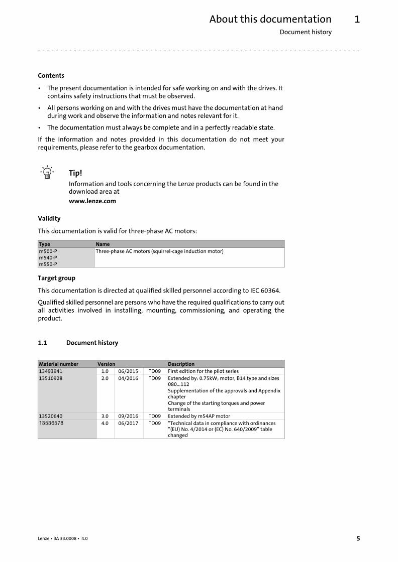
Validity
This documentation is valid for three−phase AC motors:
Type Name
m500−Pm540−Pm550−P
Three−phase AC motors (squirrel−cage induction motor)
Target group
This documentation is directed at qualified skilled personnel according to IEC 60364.
Qualified skilled personnel are persons who have the required qualifications to carry outall activities involved in installing, mounting, commissioning, and operating theproduct.
1.1 Document history
Material number Version Description
13493941 1.0 06/2015 TD09 First edition for the pilot series
13510928 2.0 04/2016 TD09 Extended by: 0.75kW; motor, B14 type and sizes080...112Supplementation of the approvals and AppendixchapterChange of the starting torques and powerterminals
13520640 3.0 09/2016 TD09 Extended by m54AP motor
.Vbo 4.0 06/2017 TD09 "Technical data in compliance with ordinances"(EU) No. 4/2014 or (EC) No. 640/2009" tablechanged
About this documentationConventions used
1
6 Lenze ¯ BA 33.0008 ¯ 4.0
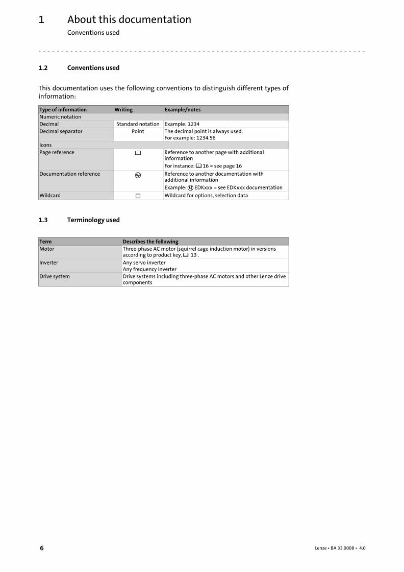
1.2 Conventions used
This documentation uses the following conventions to distinguish different types ofinformation:
Type of information Writing Example/notes
Numeric notation
Decimal Standard notation Example: 1234
Decimal separator Point The decimal point is always used.For example: 1234.56
Icons
Page reference � Reference to another page with additionalinformation
For instance: � 16 = see page 16
Documentation reference � Reference to another documentation withadditional information
Example: � EDKxxx = see EDKxxx documentation
Wildcard � Wildcard for options, selection data
1.3 Terminology used
Term Describes the following
Motor Three−phase AC motor (squirrel cage induction motor) in versionsaccording to product key, � 13 .
Inverter Any servo inverterAny frequency inverter
Drive system Drive systems including three−phase AC motors and other Lenze drivecomponents
About this documentationNotes used
1
7Lenze ¯ BA 33.0008 ¯ 4.0
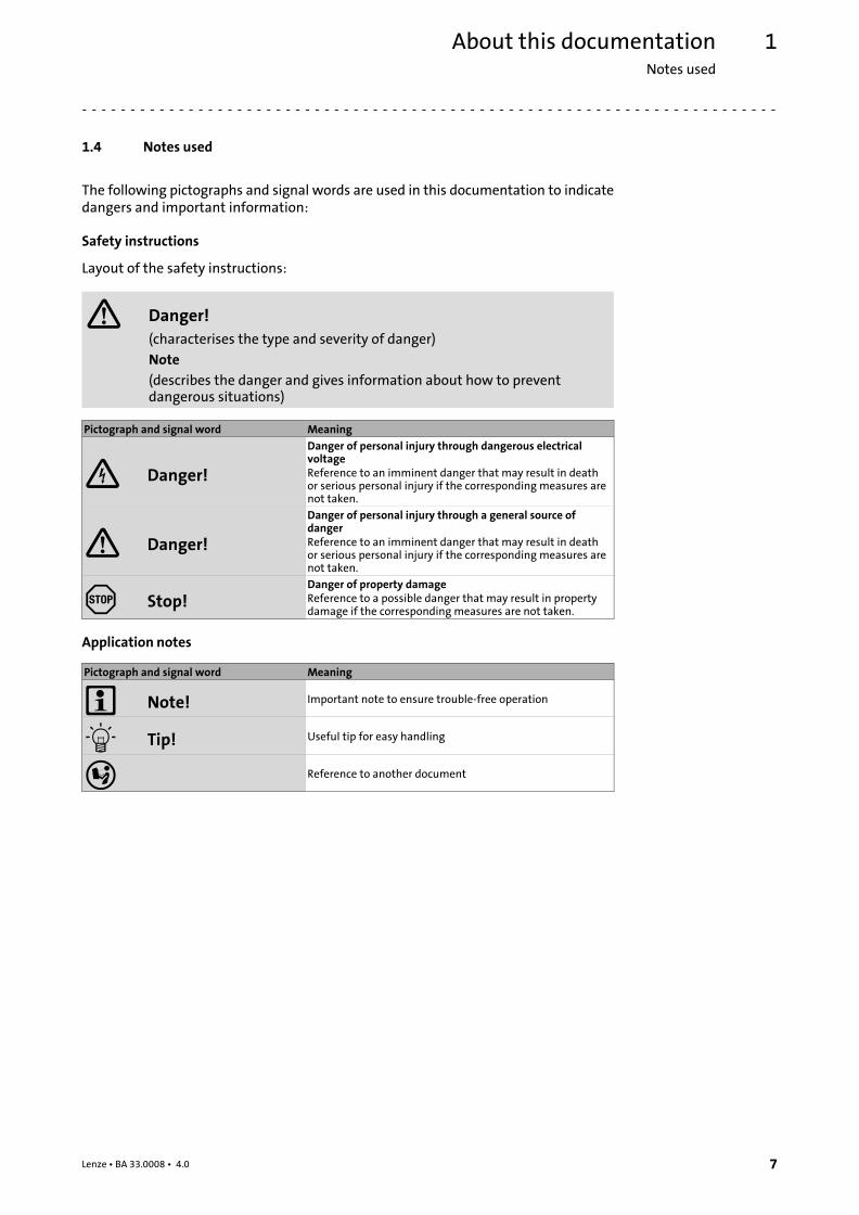
1.4 Notes used
The following pictographs and signal words are used in this documentation to indicatedangers and important information:
Safety instructions
Layout of the safety instructions:
� Danger!
(characterises the type and severity of danger)
Note
(describes the danger and gives information about how to preventdangerous situations)
Pictograph and signal word Meaning
Danger!
Danger of personal injury through dangerous electricalvoltageReference to an imminent danger that may result in deathor serious personal injury if the corresponding measures arenot taken.
� Danger!
Danger of personal injury through a general source ofdangerReference to an imminent danger that may result in deathor serious personal injury if the corresponding measures arenot taken.
Stop!Danger of property damageReference to a possible danger that may result in propertydamage if the corresponding measures are not taken.
Application notes
Pictograph and signal word Meaning
� Note! Important note to ensure trouble−free operation
� Tip! Useful tip for easy handling
� Reference to another document

Safety instructionsGeneral safety instructions for drive components
2
8 Lenze ¯ BA 33.0008 ¯ 4.0
2 Safety instructions
2.1 General safety instructions for drive components
At the time of dispatch, the drive components are in line with the latest state of the artand can be regarded as operationally safe.
Scope
The following general safety instructions apply to all Lenze drive and automationcomponents.
The product−specific safety and application notes given in this documentation must beobserved!
General hazards
� Danger!
Disregarding the following basic safety measures may lead to severepersonal injury and damage to material assets!
¯ Lenze drive and automation components ...
... must only be used for the intended purpose.
... must never be operated if damaged.
... must never be subjected to technical modifications.
... must never be operated unless completely assembled.
... must never be operated without the covers/guards.
... can − depending on their degree of protection − have live, movable or rotating partsduring or after operation. Surfaces can be hot.
¯ All specifications of the corresponding enclosed documentation must beobserved.
This is vital for safe and trouble−free operation and for achieving the specifiedproduct features.
¯ Only qualified skilled personnel are permitted to work with or on Lenze drive andautomation components.
According to IEC 60364 or CENELEC HD 384, these are persons ...
... who are familiar with the installation, assembly, commissioning and operation ofthe product,
... possess the appropriate qualifications for their work,
... and are acquainted with and can apply all the accident prevent regulations,directives and laws applicable at the place of use.
Storage
¯ In a dry, low−vibration environment without aggressive atmosphere;
¯ In the original packaging;
¯ Protect against dust and impacts;
¯ Observe climatic conditions according to the technical data.
Safety instructionsGeneral safety instructions for drive components
2
9Lenze ¯ BA 33.0008 ¯ 4.0
Storage conditions
¯ Up to one year:
– Shafts and uncoated surfaces are delivered with rust protection. Aftertreatmentis required where the corrosion protection has been damaged.
¯ More than one year, up to two years:
– Apply a long−term corrosion preventive (e.g. Anticorit BW 366 from the Fuchscompany) to the shafts and uncoated surfaces before storing the motor away.
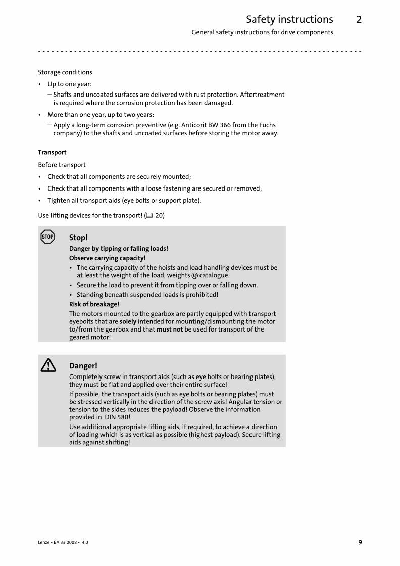
Transport
Before transport
¯ Check that all components are securely mounted;
¯ Check that all components with a loose fastening are secured or removed;
¯ Tighten all transport aids (eye bolts or support plate).
Use lifting devices for the transport! (� 20)
Stop!
Danger by tipping or falling loads!
Observe carrying capacity!
¯ The carrying capacity of the hoists and load handling devices must beat least the weight of the load, weights � catalogue.
¯ Secure the load to prevent it from tipping over or falling down.
¯ Standing beneath suspended loads is prohibited!
Risk of breakage!
The motors mounted to the gearbox are partly equipped with transporteyebolts that are solely intended for mounting/dismounting the motorto/from the gearbox and that must not be used for transport of thegeared motor!
� Danger!
Completely screw in transport aids (such as eye bolts or bearing plates),they must be flat and applied over their entire surface!
If possible, the transport aids (such as eye bolts or bearing plates) mustbe stressed vertically in the direction of the screw axis! Angular tension ortension to the sides reduces the payload! Observe the informationprovided in DIN 580!
Use additional appropriate lifting aids, if required, to achieve a directionof loading which is as vertical as possible (highest payload). Secure liftingaids against shifting!
Safety instructionsApplication as directed
2
10 Lenze ¯ BA 33.0008 ¯ 4.0
Corrosion protection
Lenze offers paints with different resistance characteristics for drive systems. Since theresistance may be reduced when the paint coat is damaged, defects in paint work (e.g.through transport or assembly) must be removed professionally to reach the requiredcorrosion resistance.
Mechanical installation
¯ Provide for careful handling and avoid mechanical overload. During handlingneither bend components, nor change the insulation distances.
Electrical installation
¯ Carry out the electrical installation according to the relevant regulations (e. g.cable cross−sections, fusing, connection to the PE conductor). Additional notes areincluded in the documentation.
¯ Only plug in or remove pluggable terminals in the deenergised state!
Commissioning
¯ If required, you have to equip the system with additional monitoring andprotective devices in accordance with the respective valid safety regulations (e. g.law on technical equipment, regulations for the prevention of accidents).
¯ Before commissioning remove transport locking devices and keep them for latertransports.
2.2 Application as directed
All products which this documentation applies to are no household appliances but areexclusively intended as components for re−utilisation for commercial use orprofessional use in terms of IEC/EN 61000−3−2. They meet the requirements of theLow−Voltage Directive 2006/95/EC and the requirements of the harmonised standardsof the IEC/EN 60034 series.
Only use the products under the operating conditions and power limits specified in thisdocumentation.
Do not use the brakes installed as fail−safe brakes. It cannot be ruled out that the brakingtorque is reduced by disruptive factors which cannot be influenced.
Low−voltage machines with IP23 protection or less are only intended for outdoor usewhen applying special protective features.
Products included in the scope of application of the EU regulations (EG) 640/2009and (EU) 4/2014 (and hence ErP Directive 2009/125/EG) and which did not complywith minimum efficiency requirements when first put into circulation, are not CEcompliant and will not receive CE marking. The product is for exclusive use outsidethe European Economic Area (EEA) only.
Any other use shall be deemed inappropriate!
Safety instructionsForeseeable misuse
2
11Lenze ¯ BA 33.0008 ¯ 4.0
2.3 Foreseeable misuse
¯ Do not operate the motors
– ... in explosion−protected areas
– ... in aggressive environments (acid, gas, vapour, dust, oil)
– ... in water
– ... in radiation environments
� Note!
Increased surface and corrosion protection can be achieved by usingadapted coating systems.
2.4 Residual hazards
Protection of persons
¯ The motor surfaces can become very hot. Danger of burns when touching!
– Provide protection against accidental contact, if necessary.
¯ Danger of unintentional starting or electrical shocks
– Connections must only be made when the equipment is deenergised and themotor is at standstill.
– Installed brakes are no fail−safe brakes.
Motor protection
¯ Installed thermal detectors are no full protection for the machine.
– Installed overload protection does not prevent an overload under anyconditions.
¯ Installed brakes are no fail−safe brakes.
– The torque may be reduced by disruptive factors that cannot be influenced suchas contamination by oil.
¯ Fuses are no motor protection.
– Use current−dependent motor protection switches at average operatingfrequency.
– Use installed thermal detectors at high operating frequency.
¯ Too high torques cause a fraction of the motor shaft.
– The maximum torques according to catalogue must not be exceeded.
¯ Lateral forces from the motor shaft may occur.
– Align shafts of motor and driving machine exactly to each other.
¯ If deviations from normal operation occur, e.g. increased temperature, noise,vibration, determine the cause and, if necessary, contact the manufacturer. If indoubt, switch off the motor.

Safety instructionsDisposal
2
12 Lenze ¯ BA 33.0008 ¯ 4.0
Fire protection
¯ Fire hazard
– Prevent contact with flammable substances.
2.5 Disposal
Sort individual parts according to their properties. Dispose of them as specified by thecurrent national regulations.
Product descriptionIdentification
Motor name
3
13Lenze ¯ BA 33.0008 ¯ 4.0
3 Product description
3.1 Identification
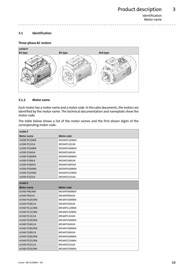
Three−phase AC motors
m550−P
B3 type B5 type B14 type
3.1.1 Motor name
Each motor has a motor name and a motor code. In the sales documents, the motors areidentified by the motor name. The technical documentation and nameplate show themotor code.
The table below shows a list of the motor names and the first eleven digits of thecorresponding motor code:
m500−P
Motor name Motor code
m500−P132M4 M50AP132M04
m500−P132L4 M50AP132L04
m500−P160M4 M50AP160M04
m500−P160L4 M50AP160L04
m500−P180M4 M50AP180M04
m500−P180L4 M50AP180L04
m500−P180V4 M50AP180V04
m500−P500M4 M50AP500M04
m500−P225M4 M50AP225M04
m500−P225L4 M50AP225L04
m540−P
Motor name Motor code
m540−P90/M4 M54AP090M04
m540−P90/L4 M54AP090L04
m540−P100/M4 M54AP100M04
m540−P100/L4 M54AP100L04
m540−P112/M4 M54AP112M04
m540−P132/M4 M54AP132M04
m540−P132/L4 M54AP132L04
m540−P160/M4 M54AP160M04
m540−P160/L4 M54AP160L04
m540−P180/M4 M54AP180M04
m540−P180/L4 M54AP180L04
m540−P200/M4 M54AP200M04
m540−P225/M4 M54AP225M04
m540−P225/L4 M54AP225L04
m540−P250/M4 M54AP250M04

Product descriptionIdentificationMotor name
3
14 Lenze ¯ BA 33.0008 ¯ 4.0
m550−P
Motor name Motor code
m550−P80/M4 M55AP080M04
m550−P90/M4 M55AP090M04
m550−P90/L4 M55AP090L04
m550−P100/M4 M55AP100M04
m550−P100/L4 M55AP100L04
m550−P112/M4 M55AP112M04
m550−P132/M4 M55AP132M04
m550−P132/L4 M55AP132L04
m550−P160/M4 M55AP160M04
m550−P160/L4 M55AP160L04
m550−P180/M4 M55AP180M04
m550−P180/L4 M55AP180L04
m550−P180/V4 M55AP180V04
m550−P200/M4 M55AP200M04
m550−P225/M4 M55AP225M04
m550−P225/L4 M55AP225L04
Product descriptionIdentification
Motor code
3
15Lenze ¯ BA 33.0008 ¯ 4.0
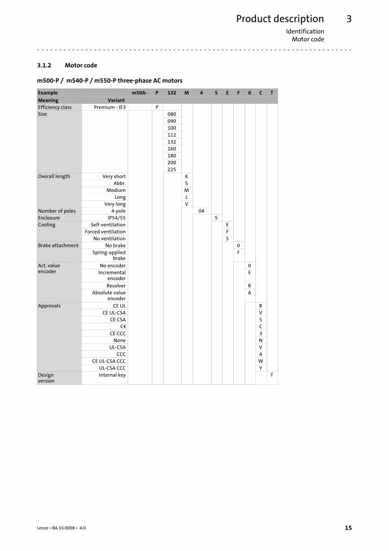
3.1.2 Motor code
m500−P / m540−P / m550−P three−phase AC motors
Example m50A− P 132 M 4 S E F 0 C T
Meaning Variant
Efficiency class Premium − IE3 P
Size 080
090
100
112
132
160
180
200
225
Overall length Very short K
Abbr. S
Medium M
Long L
Very long V
Number of poles 4−pole 04
Enclosure IP54/55 5
Cooling Self−ventilation E
Forced ventilation F
No ventilation S
Brake attachment No brake 0
Spring−appliedbrake
F
Act. valueencoder
No encoder 0
Incrementalencoder
E
Resolver R
Absolute valueencoder
A
Approvals CE UL R
CE UL−CSA V
CE CSA S
� C
CE CCC 3
None N
UL−CSA V
CCC 4
CE UL−CSA CCC W
UL−CSA CCC Y
Design version
Internal key T
Product descriptionIdentificationEncoder code
3
16 Lenze ¯ BA 33.0008 ¯ 4.0
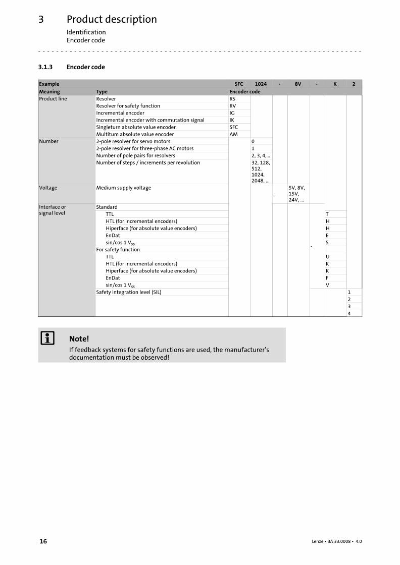
3.1.3 Encoder code
Example SFC 1024 − 8V − K 2
Meaning Type Encoder code
Product line Resolver RS
Resolver for safety function RV
Incremental encoder IG
Incremental encoder with commutation signal IK
Singleturn absolute value encoder SFC
Multitum absolute value encoder AM
Number 2−pole resolver for servo motors 0
2−pole resolver for three−phase AC motors 1
Number of pole pairs for resolvers 2, 3, 4,...
Number of steps / increments per revolution 32, 128,512,1024,2048, ...
Voltage Medium supply voltage−
5V, 8V,15V,24V, ...
Interface orsignal level
Standard
−
TTL T
HTL (for incremental encoders) H
Hiperface (for absolute value encoders) H
EnDat E
sin/cos 1 Vss S
For safety function
TTL U
HTL (for incremental encoders) K
Hiperface (for absolute value encoders) K
EnDat F
sin/cos 1 Vss V
Safety integration level (SIL) 1
2
3
4
� Note!
If feedback systems for safety functions are used, the manufacturer’sdocumentation must be observed!
Product description
Nameplate
3
17Lenze ¯ BA 33.0008 ¯ 4.0
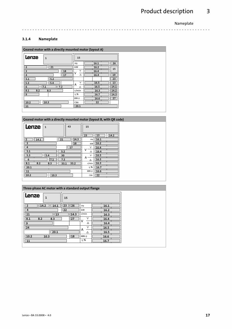
3.1.4 Nameplate
Geared motor with a directly mounted motor (layout A)
L
C86
cos �
Hz
kW
r/min
V
A
1
16.1
16.2
16.3
10.2
8.1
15
8.2 8.3
11
16.4
16.5
16.6
16.4
16.5
� %
10.3
9
2
3
4
6 7.1 7.2
5.1
5.3
5.2
5.4
18
27
14.3
14.2
14.1
13
23
16.7
22
26
19
15
17
21
20.1
Geared motor with a directly mounted motor (layout B, with QR code)
L
� %
cos �
Hz
kW
r/min
V
A
9
2
1
16.1
16.2
16.3
18
15
14.1
11
16.4
16.5
16.6
16.7
16.4
16.5
5.4
5.2
C86
14.3
17
305.3
5.1
4
3
7.27.16
33.18.1 8.2 8.3
20.1
10.2 10.3
43
23 13 14.2
22
33.2
21
Three−phase AC motor with a standard output flange
L
� %
cos �
Hz
kW
r/min
V
A
9
2
1
4
16.1
16.2
16.3
9
22
8.1
24
18
14.2
15
21
8.2 8.3
23 2614.1
11
10.2 10.3
16.4
16.5
16.6
16.7
27
14.3
16.4
16.5
13
20.1
Product description
Nameplate
3
18 Lenze ¯ BA 33.0008 ¯ 4.0
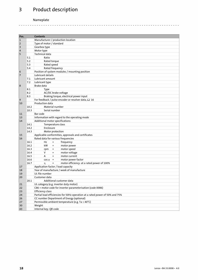
Pos. Contents
1 Manufacturer / production location
2 Type of motor / standard
3 Gearbox type
4 Motor type
5 Technical data
5.1 Ratio
5.2 Rated torque
5.3 Rated speed
5.4 Rated frequency
6 Position of system modules / mounting position
7 Lubricant details
7.1 Lubricant amount
7.2 Lubricant type
8 Brake data
8.1 Type
8.2 AC/DC brake voltage
8.3 Braking torque, electrical power input
9 For feedback / pulse encoder or resolver data, � 16
10 Production data
10.2 Material number
10.3 Serial number
11 Bar code
13 Information with regard to the operating mode
14 Additional motor specifications
14.1 Temperature class
14.2 Enclosure
14.3 Motor protection
15 Applicable conformities, approvals and certificates
16 Rated data for various frequencies
16.1 Hz = frequency
16.2 kW = motor power
16.3 rpm = motor speed
16.4 V = motor voltage
16.5 A = motor current
16.6 cos � = motor power factor
16.7 � = motor efficiency: at a rated power of 100%
17 Application factor / load capacity
18 Year of manufacture / week of manufacture
19 UL file number
20 Customer data
20.1 Additional customer data
21 UL category (e.g. inverter duty motor)
22 C86 = motor code for inverter parameterisation (code 0086)
23 Efficiency class
24 Partial load efficiencies for 50Hz operation at a rated power of 50% and 75%
26 CC number Department of Energy (optional)
27 Permissible ambient temperature (e.g. Ta � 40°C)
30 Weight
43 Internal key: QR code

Technical dataGeneral data and operating conditions
4
19Lenze ¯ BA 33.0008 ¯ 4.0
4 Technical data
4.1 General data and operating conditions
General data
Conformity and approval
Conformity
CE 2014/35/EU Low−Voltage Directive
2009/125/EC ErP DirectiveRegulation No. 4/2014 and No. 640/2009 on theecodesign of electric motors
2014/30/EU EMC Directive
EAC TP TC 004/2011(TR CU 004/2011)
On safety of low voltageequipment
Eurasian ConformityTR CU: Technical Regulation ofCustoms Union
TP TC 020/2011(TR CU 020/2011)
Electromagneticcompatibility of technicalmeans
Eurasian ConformityTR CU: Technical Regulation ofCustoms Union
Approvals
UL UL 1004−8 File No. E210321 Inverter Duty MotorsMotors and GeneratorsCSA CSA C22.2 No. 100
Energy Verified CFR Part 431.23 File No. E210321CC1278B
Energy Efficiency Program forCertain Commercial andIndustrial Equipment
CSA C390−10 Energy Efficiency TestMethods for Three−PhaseInduction Motors
CCC GB Standard12350−2009
Safety requirements of small−power motors
The applicable approvals for the product you have ordered require labelling and arespecified on the nameplate.
Protection of persons and devices
Enclosure IEC/EN 60034−5 See nameplate
Degrees of protection only apply to horizontal installation
All unused connectors must be closed with protectioncovers or blanking plugs.
Temperature class F (155 °C)IEC/EN 60034−1
Exceedance of the temperature limit weakens or destroysthe insulation
Operating conditions
Ambient conditions
Climatic
Transport IEC/EN 60721−3−2 2K3 (−20 °C ... +70 °C)
Storage IEC/EN 60721−3−1 1K3 (−20 °C ... +60 °C) < 3 months
1K3 (−20 °C ... +40 °C) > 3 months
Operation IEC/EN 60721−3−3 3K3 (−20 °C ... +40 °C) Without brake
3K3 (−10 °C ... +40 °C) With brake
> +40 °C With power reduction, seecatalogue
Site altitude < 1000 m amsl − without power reduction> 1000 m amsl < 4000m amsl with power reduction, seecatalogue
Humidity Relative humidity � 85 %, without condensation
Mechanical
IEC/EN60721−3−3 3M6
Mechanical installationImportant notes
5
20 Lenze ¯ BA 33.0008 ¯ 4.0
5 Mechanical installation
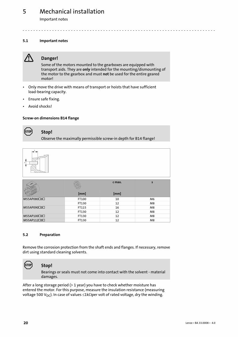
5.1 Important notes
� Danger!
Some of the motors mounted to the gearboxes are equipped withtransport aids. They are only intended for the mounting/dismounting ofthe motor to the gearbox and must not be used for the entire gearedmotor!
¯ Only move the drive with means of transport or hoists that have sufficientload−bearing capacity.
¯ Ensure safe fixing.
¯ Avoid shocks!
Screw−on dimensions B14 flange
Stop!
Observe the maximally permissible screw−in depth for B14 flange!
S
C
c max. s
[mm] [mm]
M55AP080�0� FT100 10 M6
FT130 12 M8
M55AP090�0� FT115 16 M8
FT130 12 M8
M55AP100�0� FT130 12 M8
M55AP112�0� FT130 12 M8
5.2 Preparation
Remove the corrosion protection from the shaft ends and flanges. If necessary, removedirt using standard cleaning solvents.
Stop!
Bearings or seals must not come into contact with the solvent − materialdamages.
After a long storage period (> 1 year) you have to check whether moisture hasentered the motor. For this purpose, measure the insulation resistance (measuringvoltage 500 VDC). In case of values �1k�per volt of rated voltage, dry the winding.
Mechanical installationInstallation
5
21Lenze ¯ BA 33.0008 ¯ 4.0
5.3 Installation
¯ The mounting surface must be dimensioned for the design, the weight, and thetorque of the motor.
¯ The foot and flange faces must rest flat on the mounting surface.
– An insufficient alignment of the motor shortens the service life of the rollerbearings and the transmission elements.
Blows to shafts can cause damage to the bearings.
¯ Do not exceed the permissible range of ambient operating temperature (� 19).
¯ Securely fasten the motor.
¯ Ensure unobstructed ventilation. The exhaust air, also that of adjacentaggregates, must not be inlet again immediately.
¯ During operation, surface temperatures of up to 140 °C are possible! Protectagainst contact!
� Note!
From the air inlet to other component parts, a minimum distance of 10%of the outer diameter of the fan cover must be complied with!
Ensure an even surface, solid foot or flange mounting and exact alignment if a directclutch is connected. Avoid resonances with the rotational frequency and double supplyfrequency which may be caused during assembly.
Only mount or remove transmission elements using appropriate means. In order tofacilitate handling, heat them beforehand. Cover belt pulleys and clutches with a touchguard.
Stop!
Ensure a correct belt tension!
The machines are halfkey balanced. The clutch must be halfkey balanced, too. Thevisible jutting out part of the key must be removed.
Designs with shaft end at the bottom must be protected with a cover at the N−end,preventing the ingress of foreign particles into the fan.
Mechanical installationAssembly of built−on accessories
5
22 Lenze ¯ BA 33.0008 ¯ 4.0
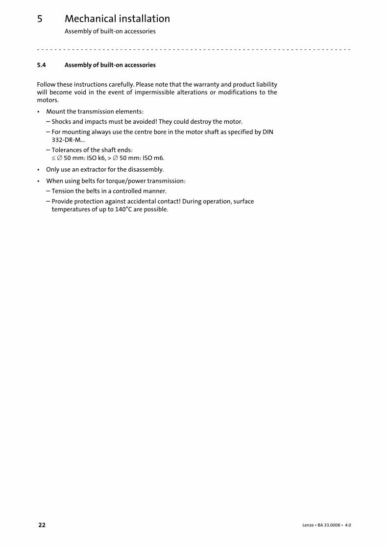
5.4 Assembly of built−on accessories
Follow these instructions carefully. Please note that the warranty and product liabilitywill become void in the event of impermissible alterations or modifications to themotors.
¯ Mount the transmission elements:
– Shocks and impacts must be avoided! They could destroy the motor.
– For mounting always use the centre bore in the motor shaft as specified by DIN332−DR−M...
– Tolerances of the shaft ends:��� 50 mm: ISO k6, > � 50 mm: ISO m6.
¯ Only use an extractor for the disassembly.
¯ When using belts for torque/power transmission:
– Tension the belts in a controlled manner.
– Provide protection against accidental contact! During operation, surfacetemperatures of up to 140°C are possible.
Mechanical installationSpring−applied brakes
5
23Lenze ¯ BA 33.0008 ¯ 4.0
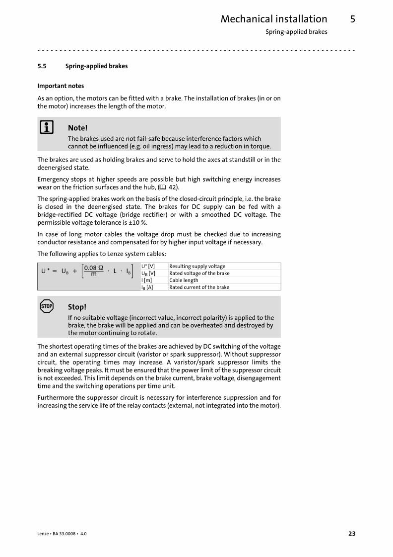
5.5 Spring−applied brakes
Important notes
As an option, the motors can be fitted with a brake. The installation of brakes (in or onthe motor) increases the length of the motor.
� Note!
The brakes used are not fail−safe because interference factors whichcannot be influenced (e.g. oil ingress) may lead to a reduction in torque.
The brakes are used as holding brakes and serve to hold the axes at standstill or in thedeenergised state.
Emergency stops at higher speeds are possible but high switching energy increaseswear on the friction surfaces and the hub, (� 42).
The spring−applied brakes work on the basis of the closed−circuit principle, i.e. the brakeis closed in the deenergised state. The brakes for DC supply can be fed with abridge−rectified DC voltage (bridge rectifier) or with a smoothed DC voltage. Thepermissible voltage tolerance is ±10 %.
In case of long motor cables the voltage drop must be checked due to increasingconductor resistance and compensated for by higher input voltage if necessary.
The following applies to Lenze system cables:
U *��� UB� �� �0.08��m � �� L� �� IB� U* [V] Resulting supply voltage
UB [V] Rated voltage of the brake
l [m] Cable length
IB [A] Rated current of the brake
Stop!
If no suitable voltage (incorrect value, incorrect polarity) is applied to thebrake, the brake will be applied and can be overheated and destroyed bythe motor continuing to rotate.
The shortest operating times of the brakes are achieved by DC switching of the voltageand an external suppressor circuit (varistor or spark suppressor). Without suppressorcircuit, the operating times may increase. A varistor/spark suppressor limits thebreaking voltage peaks. It must be ensured that the power limit of the suppressor circuitis not exceeded. This limit depends on the brake current, brake voltage, disengagementtime and the switching operations per time unit.
Furthermore the suppressor circuit is necessary for interference suppression and forincreasing the service life of the relay contacts (external, not integrated into the motor).

Mechanical installationSpring−applied brakesLocking of the manual release
5
24 Lenze ¯ BA 33.0008 ¯ 4.0
For permissible operating speeds and characteristics, please see the motor catalogueapplicable in each case. Emergency stops at higher speeds are possible, but highswitching energy increases wear on the friction surfaces and the hub.
Stop!
The friction surfaces must always be free from oil and grease becauseeven small amounts of grease or oil will considerably reduce the brakingtorque.
The formula below provides a simplified way to calculate friction energy per switchingcycle which must not exceed the limit value for emergency stops that depends on theoperating frequency (� motor catalogue; Lenze drive solutions: formulas,dimensioning, and tables).
Q� �� ½� �� Jtot� �� ��2� ��MK
MK � ML
Q [J] Friction energy
Jtot [kgm2] Total mass inertia (motor + load)
� [1/s] Angular velocity =2�n/60, n= speed [rpm]
MK [Nm] Characteristic torque
ML [Nm] Load torque
Depending on the operating conditions and possible heat dissipation, surfacetemperatures can be up to 130 °C.
� More detailed information on the used brakes is provided in thecorresponding catalogues.
5.6 Locking of the manual release
Scope of supply
Geared motor Shipping bag
GT−GNG−GST−010.iso/dms GT−GXX−012.iso/dmsGT−GXX−013.iso/dms
¯ 1 Manual release lever with knob¯ 1 Terminal block¯ 1 Cheese head screw with nut
Mechanical installationSpring−applied brakes
Locking of the manual release
5
25Lenze ¯ BA 33.0008 ¯ 4.0
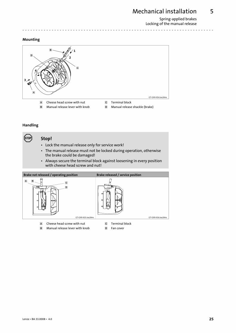
Mounting
�
�
�
�2
1
3
4
GT−GXX−014.iso/dms
� Cheese head screw with nut � Terminal block
� Manual release lever with knob � Manual release shackle (brake)
Handling
Stop!
¯ Lock the manual release only for service work!
¯ The manual release must not be locked during operation, otherwisethe brake could be damaged!
¯ Always secure the terminal block against loosening in every positionwith cheese head screw and nut!
Brake not released / operating position Brake released / service position
� ��
�
GT−GXX−015.iso/dms GT−GXX−016.iso/dms
� Cheese head screw with nut � Terminal block
� Manual release lever with knob � Fan cover
Electrical installationImportant notes
6
26 Lenze ¯ BA 33.0008 ¯ 4.0
6 Electrical installation
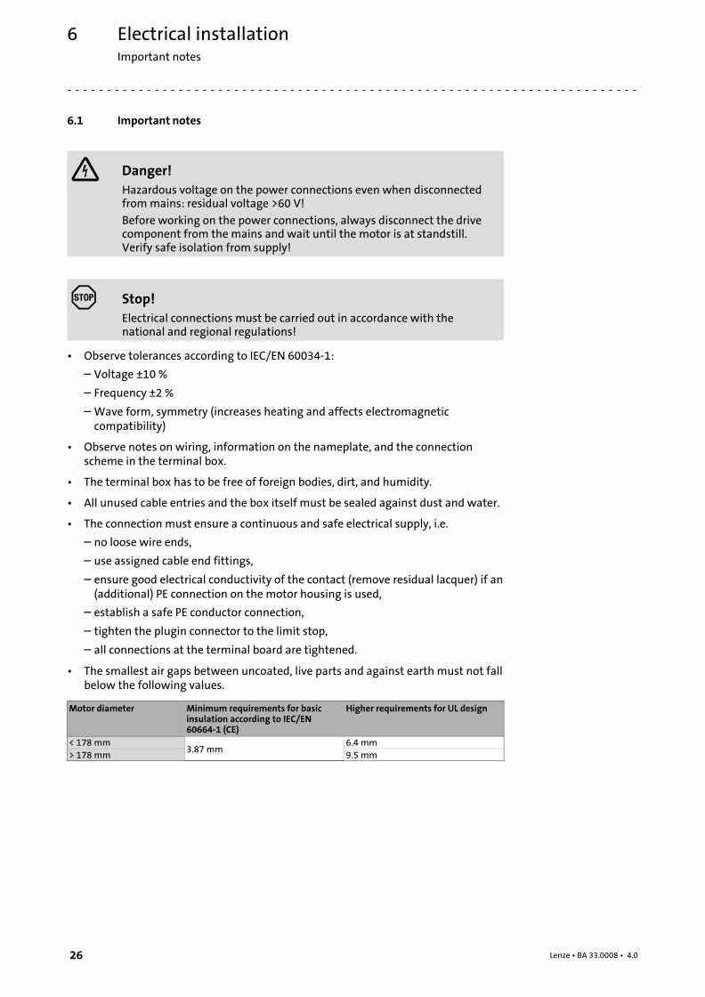
6.1 Important notes
Danger!
Hazardous voltage on the power connections even when disconnectedfrom mains: residual voltage >60 V!
Before working on the power connections, always disconnect the drivecomponent from the mains and wait until the motor is at standstill.Verify safe isolation from supply!
Stop!
Electrical connections must be carried out in accordance with thenational and regional regulations!
¯ Observe tolerances according to IEC/EN 60034−1:
– Voltage ±10 %
– Frequency ±2 %
– Wave form, symmetry (increases heating and affects electromagneticcompatibility)
¯ Observe notes on wiring, information on the nameplate, and the connectionscheme in the terminal box.
¯ The terminal box has to be free of foreign bodies, dirt, and humidity.
¯ All unused cable entries and the box itself must be sealed against dust and water.
¯ The connection must ensure a continuous and safe electrical supply, i.e.
– no loose wire ends,
– use assigned cable end fittings,
– ensure good electrical conductivity of the contact (remove residual lacquer) if an(additional) PE connection on the motor housing is used,
– establish a safe PE conductor connection,
– tighten the plugin connector to the limit stop,
– all connections at the terminal board are tightened.
¯ The smallest air gaps between uncoated, live parts and against earth must not fallbelow the following values.
Motor diameter Minimum requirements for basicinsulation according to IEC/EN60664−1 (CE)
Higher requirements for UL design
< 178 mm3.87 mm
6.4 mm
> 178 mm 9.5 mm
Electrical installationImportant notes
6
27Lenze ¯ BA 33.0008 ¯ 4.0
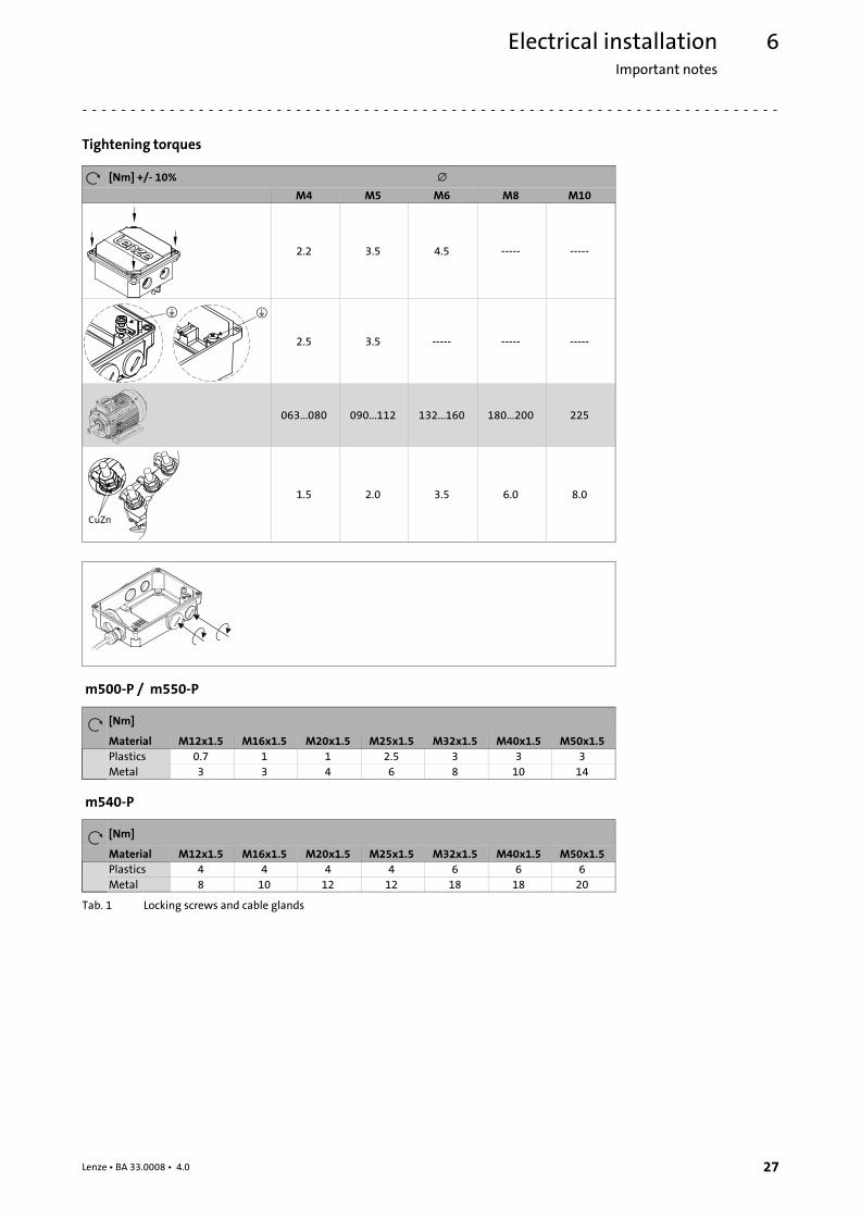
Tightening torques
[Nm] +/− 10% �
M4 M5 M6 M8 M10
2.2 3.5 4.5 −−−−− −−−−−
2.5 3.5 −−−−− −−−−− −−−−−
063...080 090...112 132...160 180...200 225
CuZn
1.5 2.0 3.5 6.0 8.0
m500−P / m550−P
[Nm]
Material M12x1.5 M16x1.5 M20x1.5 M25x1.5 M32x1.5 M40x1.5 M50x1.5
Plastics 0.7 1 1 2.5 3 3 3
Metal 3 3 4 6 8 10 14
m540−P
[Nm]
Material M12x1.5 M16x1.5 M20x1.5 M25x1.5 M32x1.5 M40x1.5 M50x1.5
Plastics 4 4 4 4 6 6 6
Metal 8 10 12 12 18 18 20
Tab. 1 Locking screws and cable glands
Electrical installationThree−phase AC motor operation on a frequency inverter
6
28 Lenze ¯ BA 33.0008 ¯ 4.0
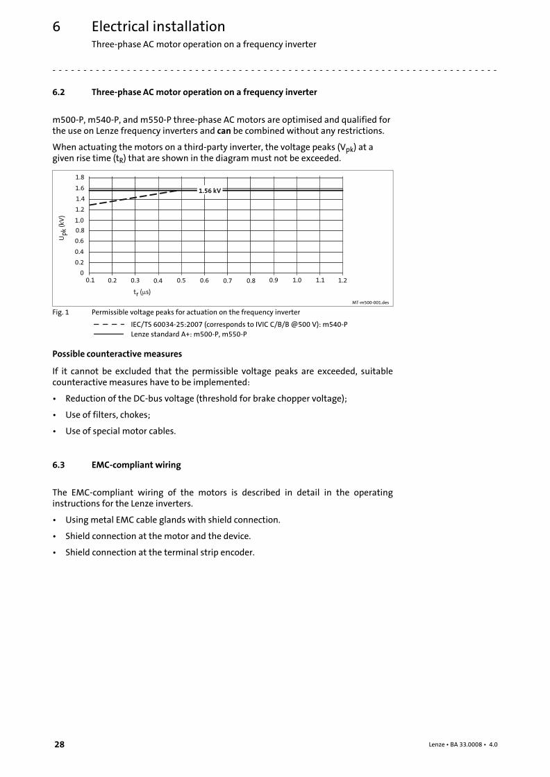
6.2 Three−phase AC motor operation on a frequency inverter
m500−P, m540−P, and m550−P three−phase AC motors are optimised and qualified forthe use on Lenze frequency inverters and can be combined without any restrictions.
When actuating the motors on a third−party inverter, the voltage peaks (Vpk) at agiven rise time (tR) that are shown in the diagram must not be exceeded.
0.2 0.4 0.6 0.8 1.0 1.20
0.2
0.4
0.6
0.8
1.0
1.2
1.4
1.6
1.8
1.56 kV
tr ( s)�
Up
k(k
V)
0.1 0.3 0.5 0.7 0.9 1.1
MT−m500−001.des
Fig. 1 Permissible voltage peaks for actuation on the frequency inverter
IEC/TS 60034−25:2007 (corresponds to IVIC C/B/B @500 V): m540−P
Lenze standard A+: m500−P, m550−P
Possible counteractive measures
If it cannot be excluded that the permissible voltage peaks are exceeded, suitablecounteractive measures have to be implemented:
¯ Reduction of the DC−bus voltage (threshold for brake chopper voltage);
¯ Use of filters, chokes;
¯ Use of special motor cables.
6.3 EMC−compliant wiring
The EMC−compliant wiring of the motors is described in detail in the operatinginstructions for the Lenze inverters.
¯ Using metal EMC cable glands with shield connection.
¯ Shield connection at the motor and the device.
¯ Shield connection at the terminal strip encoder.

Electrical installationEMC−compliant wiring
Power connections on the terminal board
6
29Lenze ¯ BA 33.0008 ¯ 4.0
6.3.1 Power connections on the terminal board
Motor
Multivoltage motors
M50AP, M55AP M54AP
L1 L2 L3
V5
U1 V1 W1
U5 W5
U2 V2 W2
L1 L2 L3
U1 V1 W1
U5 W5
U2 V2 W2
V5
L1 L2 L3
V3
U1 V1 W1
U3 W3
U2 V2 W2
L1 L2 L3
U1 V1 W1
U3 W3
U2 V2 W2
V3
MT_MXXXX_001.iso/dms
Legend for the circuit diagrams
L1/L2/L3 Power connection
�� Low voltage
� High voltage
Temperature monitoring
Terminal strip / terminal board
Contact Meaning Note
(1)TB1 Thermal contact − TCO Max. 250 V~Max. 1.6 A ~(1)TB2
(1)TP1 PTC thermistor
(1)TP2
(1)R1 Thermal sensor +KTYObserve polarity
(1)R2 Thermal sensor −KTY
Terminal board or terminal possible for all thermal sensors.
Blowers via blower terminal box / motor terminal box
Blower 3~
Terminal board
Contact Meaning Note
U1 Connection to L1 − mainsObserve direction of rotation! In case of wrongdirection of rotation, L1 − L2 must be interchanged
V1 Connection to L2 − mains
W1 Connection to L3 − mains
Separate fan 1~
Terminal board
Contact Meaning Note
U1 Connection to L1 − mains
V1 / U2 Connection to N − mains
Electrical installationEMC−compliant wiringBrake connection to terminal
6
30 Lenze ¯ BA 33.0008 ¯ 4.0
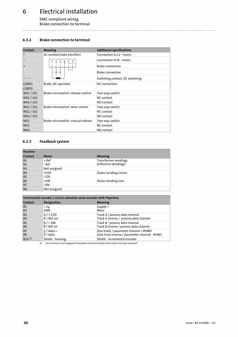
6.3.2 Brake connection to terminal
Contact Meaning Additional specifications
~ AC−excited brake (rectifier) Connection to L1 − mains
~ 1 2 3 4 5 6
- ~ ~ +Connection to N − mains
+ Brake connection
− Brake connection
Switching contact, DC switching
(1)BD1 Brake, DC operated DC connection
(1)BD2
MS1 / 2S1 Brake microswitch, release control Two−way switch
MS2 / 2S2 NC contact
MS4 / 2S3 NO contact
MS1 / 3S1 Brake microswitch, wear control Two−way switch
MS2 / 3S2 NC contact
MS4 / 3S3 NO contact
MS1 Brake microswitch, manual release Two−way switch
MS2 NC contact
MS4 NO contact
6.3.3 Feedback system
Resolver
Contact Name Meaning
B1B2
+ Ref− Ref
Transformer windings(reference windings)
B3 Not assigned
B4B5
+COS−COS
Stator winding cosine
B6B7
+SIN−SIN
Stator winding sine
B8 Not assigned
Incremental encoder / sin/cos absolute value encoder with Hiperface
Contact Designation Meaning
B1B2
+ UBGND
Supply +Mass
B3B4
A / + COSA / Ref cos
Track A / process data channelTrack A inverse / process data channel
B5B6
B / + SINB / Ref sin
Track B / process data channelTrack B inverse / process data channel
B7B8
Z / data +Z / data −
Zero track / parameter channel + RS485Zero track inverse / parameter channel − RS485
B10 1) Shield − housing Shield − incremental encoder1) The terminal is not assigned if insulation at N−end shield of the motor has been selected!

Electrical installationPlug connectors
Motor plug connection assignment
6
31Lenze ¯ BA 33.0008 ¯ 4.0
6.4 Plug connectors
Only for m500−P / m550−P
Stop!
¯ Tighten the coupling ring of the connector.
¯ If plugs without SpeedTec bayonet nut connectors are used, theconnector boxes for the power / encoder / fan connections must besecured by O−rings if loadings by vibration occur:– M17 connector box with O−ring 15 x 1.3 mm
– M23 connector box with O−ring 18 x 1.5 mm
Plug−in connectors (plug/connector box) with SpeedTec bayonet nutconnectors are vibration−proof.
¯ If SpeedTec bayonet nut connectors are used, O−rings must beremoved (if any)!
¯ Never disconnect plugs when voltage is being applied! Otherwise, theplugs could be destroyed! Inhibit the inverter before disconnecting theplugs!
When connecting the cable connector to the motor connector, make sure that the aidsto orientation (pos. 1) are facing each other. Only then trouble−free operation is ensured.
6.4.1 Motor plug connection assignment
� Note!
When making your selection, the motor data and permissible currents ofthe cables according to the "System cables" system manual must beobserved.
Electrical installationPlug connectorsPower connections
6
32 Lenze ¯ BA 33.0008 ¯ 4.0
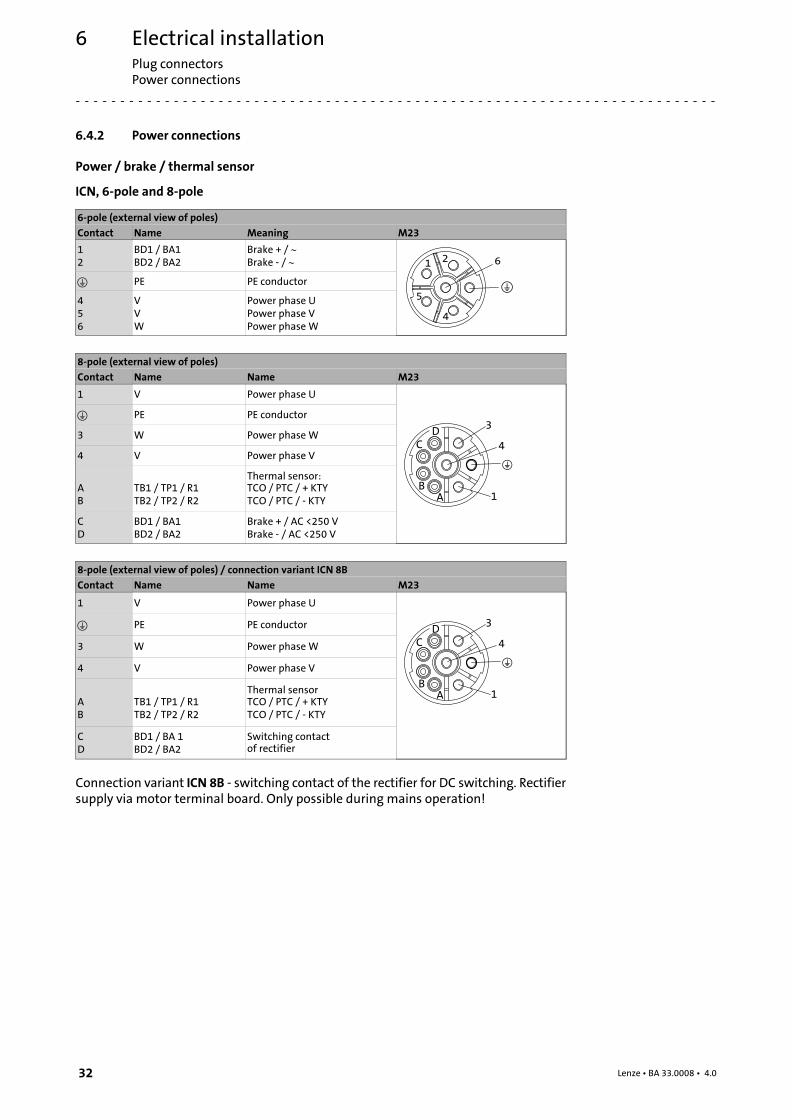
6.4.2 Power connections
Power / brake / thermal sensor
ICN, 6−pole and 8−pole
6−pole (external view of poles)
Contact Name Meaning M23
12
BD1 / BA1BD2 / BA2
Brake + / �Brake − / � 1 2
4
5
6
� PE PE conductor
456
VVW
Power phase UPower phase VPower phase W
8−pole (external view of poles)
Contact Name Name M23
1 V Power phase U
4
1
3
AB
CD
� PE PE conductor
3 W Power phase W
4 V Power phase V
AB
TB1 / TP1 / R1TB2 / TP2 / R2
Thermal sensor:TCO / PTC / + KTYTCO / PTC / − KTY
CD
BD1 / BA1BD2 / BA2
Brake + / AC <250 VBrake − / AC <250 V
8−pole (external view of poles) / connection variant ICN 8B
Contact Name Name M23
1 V Power phase U
4
1
3
AB
CD� PE PE conductor
3 W Power phase W
4 V Power phase V
AB
TB1 / TP1 / R1TB2 / TP2 / R2
Thermal sensorTCO / PTC / + KTYTCO / PTC / − KTY
CD
BD1 / BA 1BD2 / BA2
Switching contactof rectifier
Connection variant ICN 8B − switching contact of the rectifier for DC switching. Rectifiersupply via motor terminal board. Only possible during mains operation!
Electrical installationPlug connectors
Power connections
6
33Lenze ¯ BA 33.0008 ¯ 4.0
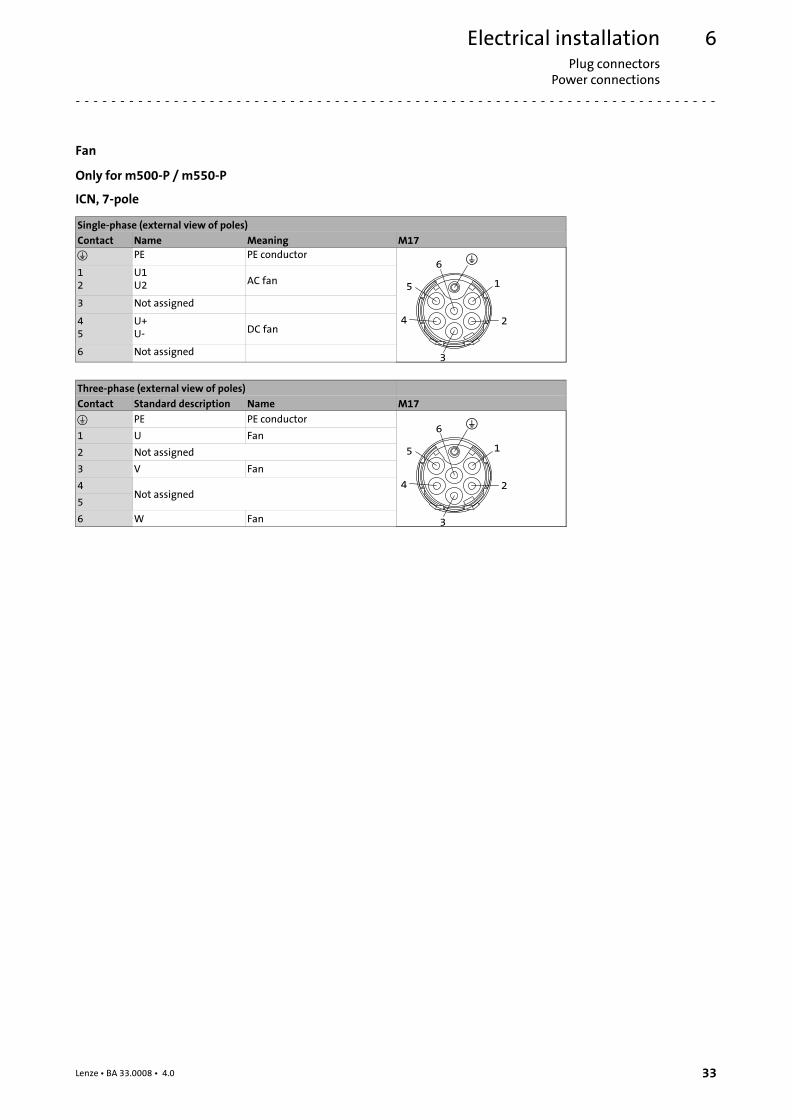
Fan
Only for m500−P / m550−P
ICN, 7−pole
Single−phase (external view of poles)
Contact Name Meaning M17
� PE PE conductor
1
4 2
5
6
3
12
U1U2 AC fan
3 Not assigned
45
U+U− DC fan
6 Not assigned
Three−phase (external view of poles)
Contact Standard description Name M17
� PE PE conductor
1
4 2
5
6
3
1 U Fan
2 Not assigned
3 V Fan
4Not assigned
5
6 W Fan
Electrical installationPlug connectorsFeedback system
6
34 Lenze ¯ BA 33.0008 ¯ 4.0
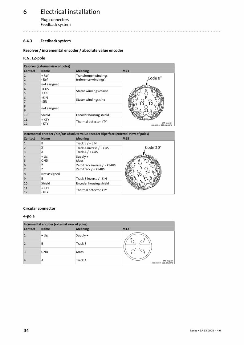
6.4.3 Feedback system
Resolver / incremental encoder / absolute value encoder
ICN, 12−pole
Resolver (external view of poles)
Contact Name Meaning M23
12
+ Ref− Ref
Transformer windings(reference windings)
MT plug−inconnector−001.iso/dms
3 not assigned
45
+COS−COS
Stator windings cosine
67
+SIN−SIN
Stator windings sine
89
not assigned
10 Shield Encoder housing shield
1112
+ KTY− KTY
Thermal detector KTY
Incremental encoder / sin/cos absolute value encoder Hiperface (external view of poles)
Contact Name Meaning M23
1 B Track B / + SIN
23
AA
Track A inverse / − COSTrack A / + COS
45
+ UBGND
Supply +Mass
67
ZZ
Zero track inverse / − RS485Zero track / + RS485
8 Not assigned
9 B Track B inverse / − SIN
10 Shield Encoder housing shield
1112
+ KTY− KTY
Thermal detector KTY
Circular connector
4−pole
Incremental encoder (external view of poles)
Contact Name Meaning M12
1 + UB Supply +
MT plug−inconnector−001.iso/dms
2 B Track B
3 GND Mass
4 A Track A
Electrical installationTerminal box HAN connectors
Feedback system
6
35Lenze ¯ BA 33.0008 ¯ 4.0
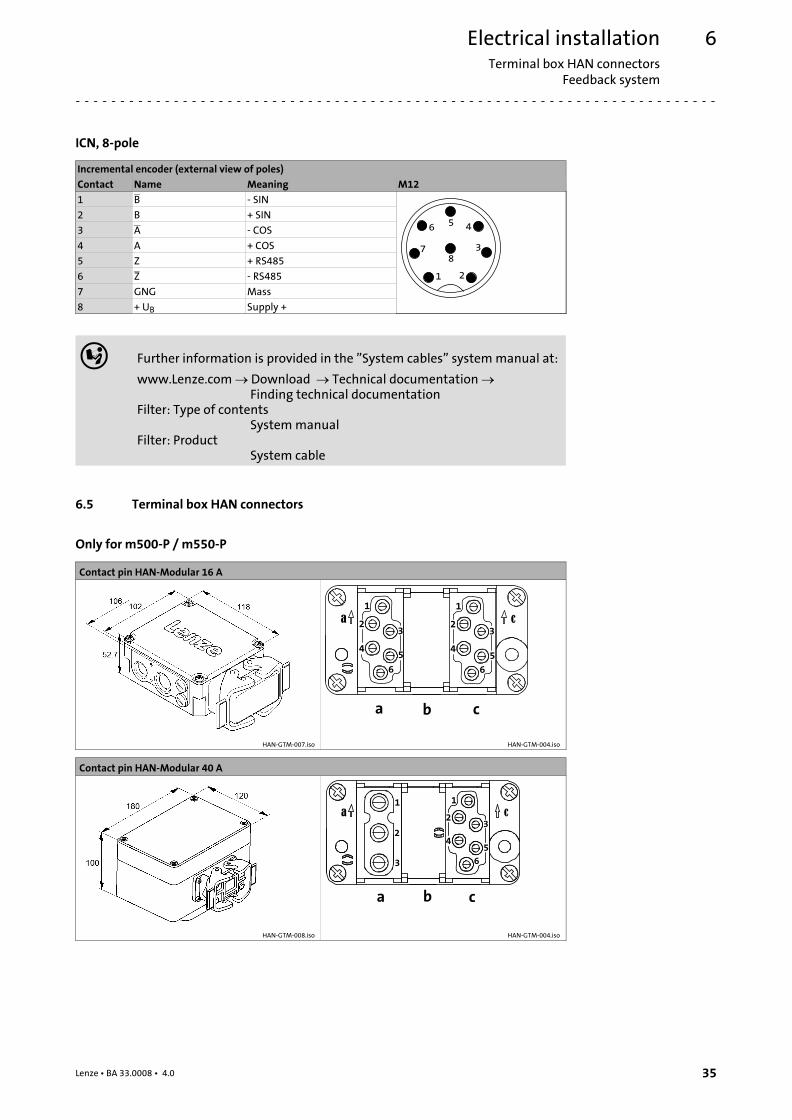
ICN, 8−pole
Incremental encoder (external view of poles)
Contact Name Meaning M12
1 B − SIN
1 2
456
378
2 B + SIN
3 A − COS
4 A + COS
5 Z + RS485
6 Z − RS485
7 GNG Mass
8 + UB Supply +
� Further information is provided in the "System cables" system manual at:
www.Lenze.com Download Technical documentation Finding technical documentation
Filter: Type of contentsSystem manual
Filter: ProductSystem cable
6.5 Terminal box HAN connectors
Only for m500−P / m550−P
Contact pin HAN−Modular 16 A
HAN−GTM−007.iso HAN−GTM−004.iso
Contact pin HAN−Modular 40 A
HAN−GTM−008.iso HAN−GTM−004.iso
Electrical installationTerminal box HAN connectorsFeedback system
6
36 Lenze ¯ BA 33.0008 ¯ 4.0
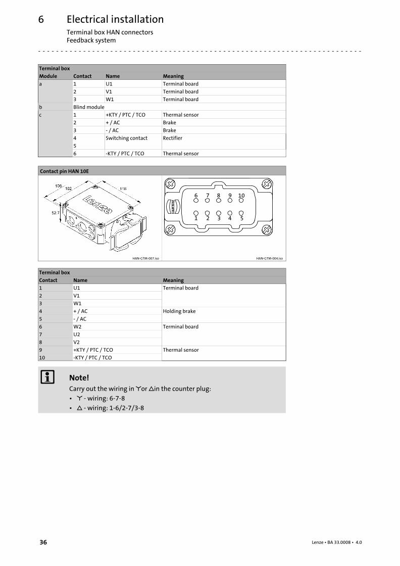
Terminal box
Module Contact Name Meaning
a 1 U1 Terminal board
2 V1 Terminal board
3 W1 Terminal board
b Blind module
c 1 +KTY / PTC / TCO Thermal sensor
2 + / AC Brake
3 − / AC Brake
4 Switching contact Rectifier
5
6 −KTY / PTC / TCO Thermal sensor
Contact pin HAN 10E
HAN−GTM−007.iso HAN−GTM−004.iso
Terminal box
Contact Name Meaning
1 U1 Terminal board
2 V1
3 W1
4 + / AC Holding brake
5 − / AC
6 W2 Terminal board
7 U2
8 V2
9 +KTY / PTC / TCO Thermal sensor
10 −KTY / PTC / TCO
� Note!
Carry out the wiring in �or �in the counter plug:
¯ � − wiring: 6−7−8
¯ � − wiring: 1−6/2−7/3−8
Commissioning and operationImportant notes
7
37Lenze ¯ BA 33.0008 ¯ 4.0
7 Commissioning and operation
7.1 Important notes
For trial run without output elements, lock the featherkey. Do not deactivate theprotective devices, not even in a trial run.
Check the correct operation of the brake before commissioning motors with brakes.
7.2 Before switching on
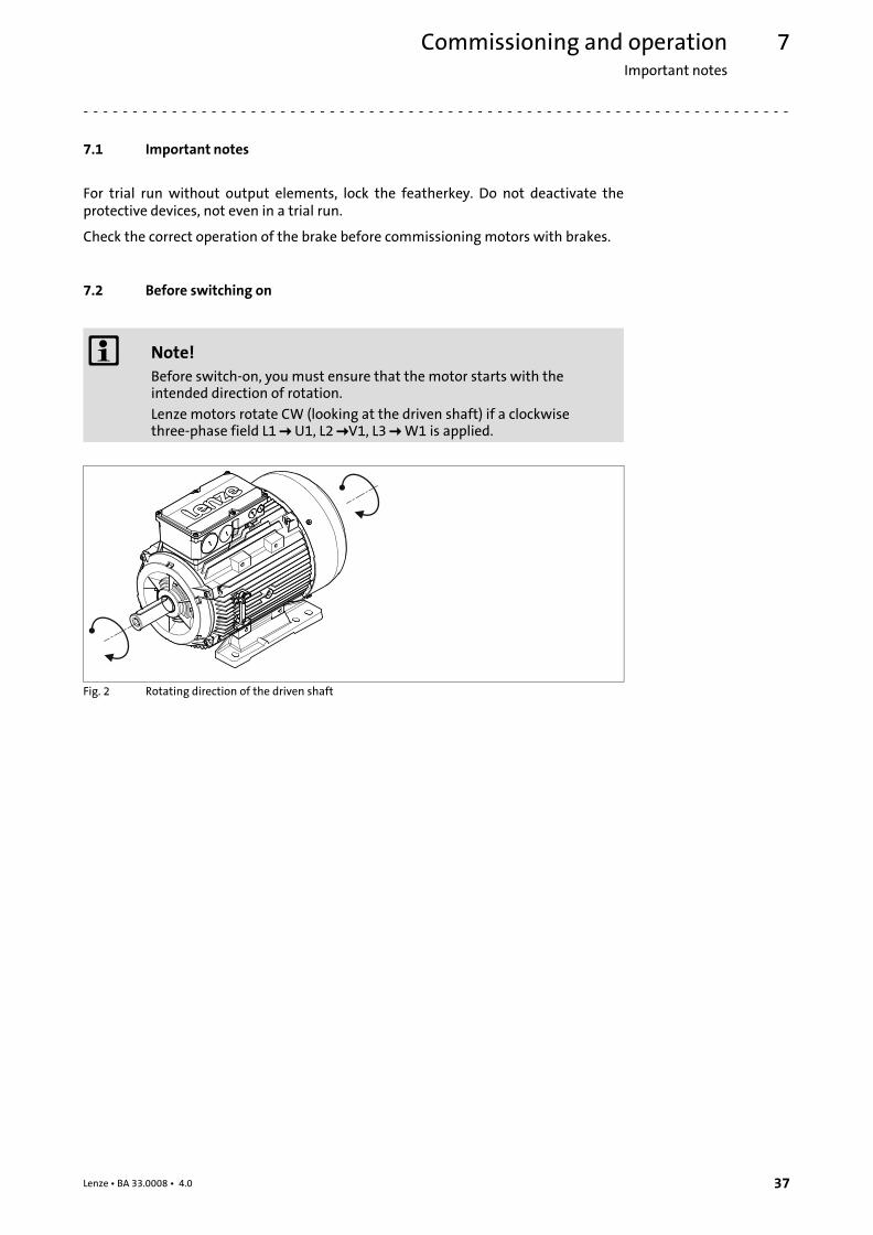
� Note!
Before switch−on, you must ensure that the motor starts with theintended direction of rotation.
Lenze motors rotate CW (looking at the driven shaft) if a clockwisethree−phase field L1 � U1, L2 �V1, L3 � W1 is applied.
Fig. 2 Rotating direction of the driven shaft

Commissioning and operationFunctional test
7
38 Lenze ¯ BA 33.0008 ¯ 4.0
Before initial commissioning, before commissioning after an extended standstillperiod, or before commissioning after an overhaul of the motor, the following must bechecked:
¯ Measure the insulation resistance, in case of values �1 k� per volt of ratedvoltage, dry the winding.
¯ Have all screwed connections of the mechanical and electrical parts been firmlytightened?
¯ Is the unrestricted supply and removal of cooling air ensured?
¯ Has the PE conductor been connected correctly?
¯ Have the protective devices against overheating (temperature sensor evaluation)been activated?
¯ Is the inverter correctly parameterised for the motor?(� Inverter operating instructions)?
¯ Are the electrical connections o.k.?
¯ Does the motor connection have the correct phase sequence?
¯ Are rotating parts and surfaces which can become very hot protected againstaccidental contact?
¯ Is the contact of good electrical conductivity if a PE connection on the motorhousing is used?
7.3 Functional test
¯ Check all functions of the drive after commissioning:
¯ Direction of rotation of the motor
– Direction of rotation in the disengaged state (see chapter "Electricalconnection").
¯ Torque behaviour and current consumption
¯ Function of the feedback system
Commissioning and operationDuring operation
7
39Lenze ¯ BA 33.0008 ¯ 4.0
7.4 During operation
Stop!
¯ Fire hazard! Do not clean or spray motors with flammable detergentsor solvents.
¯ Avoid overheating! Deposits on the drives impede the heat dissipationrequired and have to be removed regularly.
� Danger!
During operation, motor surfaces must not be touched. According to theoperating status, the surface temperature for motors can be up to 140°C.For the protection against burn injuries, provide protection againstcontact, if necessary. Observe cooling−off times!
During operation, carry out inspections on a regular basis. Pay special attention to:
¯ Unusual noises
¯ Oil spots on drive end or leakages
¯ Irregular running
¯ Increased vibration
¯ Loose fixing elements
¯ Condition of electrical cables
¯ Speed variations
¯ Impeded heat dissipation
– Deposits on the drive system and in the cooling channels
– Pollution of the air filter
In case of irregularities or faults: (� 51).
Maintenance/repairImportant notesMotor
8
40 Lenze ¯ BA 33.0008 ¯ 4.0
8 Maintenance/repair
8.1 Important notes
Danger!
Hazardous voltage on the power connections even when disconnectedfrom mains: residual voltage >60 V!
Before working on the power connections, always disconnect the drivecomponent from the mains and wait until the motor is at standstill.Verify safe isolation from supply!
Shaft sealing rings and roller bearings have a limited service life.
Regrease bearings with relubricating devices while the low−voltage machine is running.Only use the grease recommended by the manufacturer.
If the grease drain holes are sealed with a plug, (IP54 drive end; IP23 drive and nondriveend), remove plug before commissioning. Seal bore holes with grease.
8.2 Maintenance intervals
Inspections
¯ If the machine is exposed to dirt, clean the air channels regularly.
8.2.1 Motor
¯ Only the bearings and shaft sealing rings become worn.
– Check bearings for noise (after approx. 15,000 h at the latest).
¯ In order to prevent overheating, remove dirt deposits on the drives regularly.
¯ We recommend carrying out an inspection after the first 50 operating hours. Inthis way, you can detect and correct any irregularities or faults at an early stage.
8.2.2 Encoder
Stop!
Repair work or replacement of defective safety encoders must only becarried out by Lenze service personnel!
After a service life of 10 years, an inspection of the metal elastomer torque plate isrequired for the AS1024−8V−K, AS1024−8V−K2; AM1024−8V−K, and AM1024−8V−K2encoders. If no replacement is required, an inspection interval of max. 5 years has to beobserved.
Maintenance/repairMaintenance operations
Spring−operated brakes
8
41Lenze ¯ BA 33.0008 ¯ 4.0
8.2.3 Spring−operated brakes
To ensure safe and trouble−free operation, spring−applied brakes must be checked andmaintained at regular intervals. Servicing can be made easier if good accessibility of thebrakes is provided in the plant. This must be considered when installing the drives in theplant.
Primarily, the necessary maintenance intervals for industrial brakes result from the loadduring operation. When calculating the maintenance interval, all causes for wear mustbe taken into account, ((� 43). For brakes with low loads such as holding brakes withemergency stop, we recommend a regular inspection at a fixed time interval. To reducethe cost, the inspection can be carried out along with other regular maintenance workin the plant if necessary.
If the brakes are not maintained, failures, production losses or damage to the systemmay occur. Therefore, a maintenance concept adapted to the particular operatingconditions and brake loads must be defined for every application. For the spring−appliedbrakes, the maintenance intervals and maintenance operations listed in the belowtable must be provided. The maintenance operations must be carried out as describedin the detailed descriptions.
Type Service brake Holding brake with emergency stop
Spring−applied brake ¯ according to service lifecalculation
¯ otherwise every six months¯ after 4,000 operating hours at the
latest
¯ at least every two years¯ after 1 million cycles at the latest¯ provide shorter intervals in the
case of frequent emergency stops
8.3 Maintenance operations
8.3.1 Motor
Stop!
¯ Make sure that no foreign bodies can enter the inside of the motor!
¯ Do not remove plugs when voltage is being applied!
� Danger!
¯ Only work on the motor when it is deenergised!
¯ Hot motor surfaces of up to 140 °C. Observe cooling times!
¯ Remove loads acting on motors or secure loads acting on the drive!

Maintenance/repairMaintenance operationsSpring−operated brakes
8
42 Lenze ¯ BA 33.0008 ¯ 4.0
8.3.2 Spring−operated brakes
The brake is mounted to the N−end shield of the motor. Remove the fan cover or blowerunit or the encoder, if available, to check, maintain, or set the brake.
� Note!
Brakes with defective armature plates, cheese head screws, springs orcounter friction faces must always be replaced completely.
Generally observe the following for inspections and maintenance works:
¯ Remove oil and grease linked impurities using brake cleaning agents, ifnecessary, replace brake after identifying the cause of thecontamination. Dirt deposits in the air gap between stator andarmature plate impair the function of the brake and must be removed.
¯ After replacing the rotor, the original braking torque will not bereached until the run−in operation of the friction surfaces has beencompleted. After replacing the rotor, run−in armature plates andcounter friction faces have an increased initial rate of wear.
Wear on spring−applied brakes
The used spring−applied brakes have a low rate of wear and are designed for longmaintenance intervals.
However, the friction lining, the teeth between the brake rotor and the hub, and also thebraking mechanism are naturally subject to function−related wear which depends onthe application case (see table). In order to ensure safe and problem−free operation, thebrake must therefore be checked and maintained regularly and, if necessary, replaced(see brake maintenance and inspection).
The following table describes the different causes of wear and their effect on thecomponents of the spring−applied brake. In order to calculate the useful life of the rotorand brake and determine the maintenance intervals to be prescribed, the relevantinfluencing factors must be quantified. The most important factors are the appliedfriction energy, the starting speed of braking and the switching frequency. If several ofthe indicated causes of wear on the friction lining occur in an application, their effectsare to be added together.

Maintenance/repairMaintenance operations
Checking the component parts
8
43Lenze ¯ BA 33.0008 ¯ 4.0
Component Effect Influencing factors Cause
Friction lining Wear on the friction lining Applied friction energy Braking during operation(impermissible, holdingbrakes!)
Emergency stops
Overlapping wear whenthe drive starts and stops
Active braking by the drivemotor with the help of thebrake (quick stop)
Number of start−stopcycles
Starting wear if motor ismounted in a positionwith the shaft vertical,even if the brake is open
Armature plate andflange
Running−in of armatureplate and flange
Applied friction energy Friction between the brakelining and the armatureplate or flange e.g. duringemergency braking orservice brake operation
Teeth of the brakerotor
Teeth wear (primarily atthe rotor end)
Number of start−stopcycles,Level of the brakingtorque,Dynamics of theapplication,Speed fins in operation
Relative movement andimpacts between brakerotor and brake hub
Armature platebracket
Armature plate, cap screwsand bolts are deflected
Number of start−stopcycles,Level of braking torque
Load changes and impactsdue to reversal errorduring interactionbetween armature plate,cap screws and guide bolts
Springs Fatigue failure of thesprings
Number of switchingoperations of the brake
Axial load cycle andshearing stress on thesprings due to radialreversing error of thearmature plate
Tab. 2 Causes for wear
8.3.3 Checking the component parts
With a mountedbrake
¯ Check ventilation function and activation/deactivation¯ Check air gap (if required, re−adjust it)¯ Measure rotor thickness (if required, replace rotor)¯ Thermal damage of the armature plate or flange (tarnished in
dark blue)
� 45� 45� 44
With a dismountedbrake
¯ Check clearance of the rotor gear teeth (replace rotors that aredamaged by vibration)
¯ Damage by vibration of the torque support at the sleeve bolts,cylindrical pins, and armature plate
¯ Check springs for damage¯ Check armature plate and flange or end shield
– Evenness for size 06...12 < 0.06 mm– Evenness from size 14 < 0.1 mm– Max. run−in depth = rated air gap of the design size
� 46
Maintenance/repairMaintenance operationsChecking the rotor thickness
8
44 Lenze ¯ BA 33.0008 ¯ 4.0
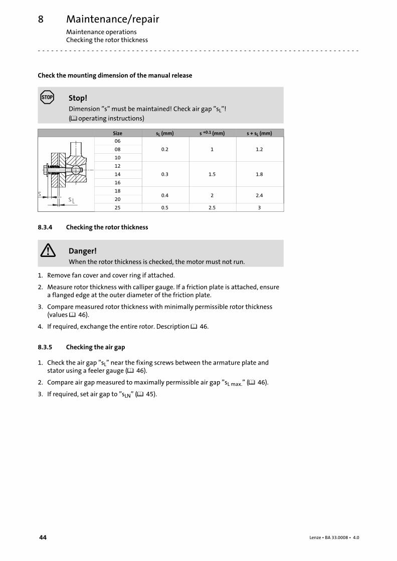
Check the mounting dimension of the manual release
Stop!
Dimension "s" must be maintained! Check air gap "sL"!
(� operating instructions)
Size sL (mm) s +0.1 (mm) s + sL (mm)
06
0.2 1 1.208
10
12
0.3 1.5 1.814
16
180.4 2 2.4
20
25 0.5 2.5 3
8.3.4 Checking the rotor thickness
� Danger!
When the rotor thickness is checked, the motor must not run.
1. Remove fan cover and cover ring if attached.
2. Measure rotor thickness with calliper gauge. If a friction plate is attached, ensurea flanged edge at the outer diameter of the friction plate.
3. Compare measured rotor thickness with minimally permissible rotor thickness(values � 46).
4. If required, exchange the entire rotor. Description � 46.
8.3.5 Checking the air gap
1. Check the air gap "sL" near the fixing screws between the armature plate andstator using a feeler gauge (� 46).
2. Compare air gap measured to maximally permissible air gap "sL max." (� 46).
3. If required, set air gap to "sLN" (� 45).
Maintenance/repairMaintenance operations
Release / voltage
8
45Lenze ¯ BA 33.0008 ¯ 4.0
8.3.6 Release / voltage
� Danger!
The rotating rotor must not be touched.
Danger!
Live connections must not be touched.
1. Observe the brake’s function while the drive is being operated. The armatureplate must be tightened and the rotor must move free of residual torque.
2. Measure the DC voltage on the brake.
– The DC voltage measured after the overexcitation time (� operatinginstructions, forced voltage rectifier) must equal the voltage for the holding. Adeviation of up to ±10 % is permissible.
8.3.7 Adjusting the air gap
� Danger!
The brake must be free of residual torque.
Stop!
For the flange design, please observe the following if the flange ismounted with additional screws:
Clearing holes in the end shield must be provided behind the threadedholes in the flange that are designed for the screws. Without clearingholes, the minimum rotor thickness cannot be utilised fully. In no casemust the screws press against the end shield.
1. Loosen screws (10).
2. Screw the sleeve bolts further into the stator using an open−jawed spanner. 1/6revolution reduces the air gap by approx. 0.15 mm.
3. Tighten screws, torques (� 46).
4. Check air gap "sL" near the screws using a feeler gauge, "sLrated" (� 46).
5. If the deviation of "sLrated" is too great, repeat the adjustment process.

Maintenance/repairInstallation of a spring−applied brakeRotor replacement
8
46 Lenze ¯ BA 33.0008 ¯ 4.0
8.3.8 Rotor replacement
� Danger!
The brake must be free of residual torque.
1. Loosen the connecting cable.
2. Evenly release the screws and remove them completely.
3. Completely remove the stator from the end shield. Observe the connecting cables.
4. Completely remove the rotor from the hub.
5. Check the toothed part of the hub.
6. In case of wear, replace the hub, too.
7. Check the friction surface of the end shield. If the flange / friction plate is severelygouged, it must be replaced. If the end shield is severely gouged, the frictionsurface must be reprocessed.
8. Measure the rotor thickness (new rotor) and the height of head of the sleeve boltsusing a caliper gauge.
9. The distance between the stator and the armature plate is calculated as follows:
Distance = rotor thickness + sLrated − height of head
"sLrated" (� 46)
10.Evenly remove the sleeve bolts until the calculated distance is reached betweenthe stator and the armature plate.
11.Mount and set new complete rotor and stator, (� 47).
12.Connect the connecting cable again.
8.4 Installation of a spring−applied brake
8.4.1 Brake characteristics
Brake size sLN +0.1 mm−0.05 mm
sLmax. service brake
sLmax. holding brake
Max. adjustment,permissible wear
path
Rotor thickness Tightening torqueof the fixing
screws
[mm] [mm] [mm] [mm] min. 1) [mm] max. [mm] [Nm]
06
0.2 0.5 0.3 1.5
4.5 6.0 3.0
08 5.5 7.0 5.9
10 7.5 9.0 10.1
12
0.3 0.75 0.45
2.0 8.0 10.0 10.1
14 2.5 7.5 10.0 24.6
16 3.5 8.0 11.5 24.6
180.4 1.0 0.6
3.0 10.0 13.0 24.6
20 4.0 12.0 16.0 48.0
25 0.5 1.25 0.75 4.5 15.5 20.0 48.0
Tab. 3 Characteristics of the spring−applied brake
1) The dimension of the friction lining allows for adjustment of the brake for at least fivetimes.
Maintenance/repairInstallation of a spring−applied brake
Installation of the brake
8
47Lenze ¯ BA 33.0008 ¯ 4.0
8.4.2 Installation of the brake
Stop!
¯ Check the state of the end shield (15). It must be free from oil andgrease.
3
415
K14.0502/8
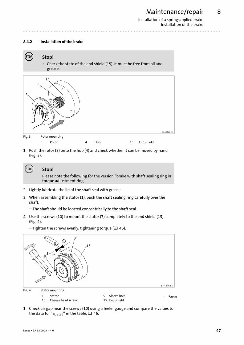
Fig. 3 Rotor mounting
3 Rotor 4 Hub 15 End shield
1. Push the rotor (3) onto the hub (4) and check whether it can be moved by hand(Fig. 3).
Stop!
Please note the following for the version "brake with shaft sealing ring intorque adjustment ring":
2. Lightly lubricate the lip of the shaft seal with grease.
3. When assembling the stator (1), push the shaft sealing ring carefully over theshaft.
– The shaft should be located concentrically to the shaft seal.
4. Use the screws (10) to mount the stator (7) completely to the end shield (15)(Fig. 4).
– Tighten the screws evenly, tightening torque (� 46).
9
110
�15
KL458−012−a
Fig. 4 Stator mounting
1 Stator 9 Sleeve bolt � sLrated
10 Cheese head screw 15 End shield
1. Check air gap near the screws (10) using a feeler gauge and compare the values tothe data for "sLrated" in the table, � 46.

Maintenance/repairInstallation of a spring−applied brakeAdjusting the air gap
8
48 Lenze ¯ BA 33.0008 ¯ 4.0
� Note!
Do not insert feeler gauge further than 10 mm between the armatureplate (2) and stator (1)!
If "sL" (� 46) is not within the tolerance, readjust the air gap.
8.4.3 Adjusting the air gap
� Danger!
Disconnect voltage. The brake must be free of residual torque.
+
−9
1
10
KL458−013−a
Fig. 5 Re−adjust air gap
1 Complete stator 10 Cheese head screw
9 Sleeve bolt
If the measured value "sL" is outside the tolerance of "sLrated", set the dimension:

Maintenance/repairInstallation of a spring−applied brake
Assembly of the friction plate, sizes 06 to 16
8
49Lenze ¯ BA 33.0008 ¯ 4.0
8.4.4 Assembly of the friction plate, sizes 06 to 16
15
27
KL458−009−a
Fig. 6 Friction plate mounting
15 End shield 27 Friction plate
1. Put a friction plate (27) or flange (6) against the end shield (15).
� Note!
The flanged edge of the friction plate must remain visible!
2. Align pitch circle and fastening bore hole thread.
8.4.5 Assembly of the flange
15
66.1
KL458−008−a
Fig. 7 Flange mounting
6 Flange 15 End shield
6.1 Set of screws
1. Hold the flange (6) against the end shield (15) and check the pitch circle andretaining screw drill hole threading.
2. Fasten the flange (6) on the end shield (15) with the screws (6.1).
3. Tighten the cheese head screws (6.1) evenly, (tightening torques (� 46).
4. Check the height of the screw heads. The screw heads may not be higher than theminimum rotor thickness. We recommend using screws according to DIN 6912,dimensions (� 46).

Maintenance/repairRepairAssembly of the cover seal
8
50 Lenze ¯ BA 33.0008 ¯ 4.0
Mounting the flange without additional screws
1. Apply the flange (6) to the end shield (15). Check pitch circle and thread of thescrew−on bore holes.
2. Mount the brake.
8.4.6 Assembly of the cover seal
15
13
1210
11.2 1 2 1
5613 27 13 10
KL458−010−a KL458−007−a
Fig. 8 Cover ring mounting
1 Complete stator 10 Cheese head screw 15 End shield
2 Armature plate 27 Friction plate
6 Flange 13 Cover ring
1. Insert the cable through the cover ring.
2. Push the cover ring over the stator.
3. Press the lips of the cover ring into the groove of rotor and flange.
– If a friction plate is used, the lip must be pulled over the flanged edge.
8.5 Repair
¯ We recommend having all repairs carried out by the Lenze customer service.

Troubleshooting and fault elimination 9
51Lenze ¯ BA 33.0008 ¯ 4.0
9 Troubleshooting and fault elimination
If faults occur during operation of the drive system:
¯ First check the possible causes of malfunction according to the following table.
� Note!
Also observe the corresponding chapters in the operating instructions forthe other components of the drive system.
If the fault cannot be remedied using one of the listed measures, please contact theLenze Service.
Fault Cause RemedyMotor too hot
Can only be evaluated bymeasuring the surfacetemperature:¯ Non−ventilated motors
� 140 °C¯ Externally ventilated or
self−ventilated motors� 110 °C
Insufficient cooling air, blocked airducts.
Ensure unimpeded circulation of cooling air
Preheated cooling air Ensure a sufficient supply of fresh cooling airOverload, with normal mains voltagethe current is too high and the speedtoo low
Use larger drive (determined by power measurement)
Rated operating mode exceeded (S1 toS8 IEC/EN 60034−1)
Adjust rated operating mode to the specified operating conditions.Determination of correct drive by expert or Lenze customer service
Loose contact in supply cable(temporary two−phase operation!)
Tighten loose contact
Fuse has blown (two−phasing!) Replace fuseOverload of the drive Check load and, if necessary, reduce by means of longer ramp−up
timesCheck winding temperature
Heat dissipation impeded by deposits Clean surface and cooling fins of the drivesMotor does not start Voltage supply interrupted Check error message on the inverter
Check electrical connection, � 26Inverter inhibited Check display on the inverter
Check inverter enableFuse has blown Replace fuseInterrupted encoder cable Check error message on the inverter
Check encoder cableBrake does not release Check electrical connection, � 26
Check air gap, � brake documentationCheck continuity of magnetic coil
Drive blocks Check components for easy movement, remove foreign particles ifnecessary
Motor cable with reverse polarity Check electrical connection, � 26Motor suddenly stops anddoes not restart
Overload monitoring of the inverter isactivated
Check inverter settingsReduce load caused by longer acceleration times
Incorrect rotating directionof the motor
Motor cable with reverse polarity Check and correct polarity
Motor rotates normally butdoes not reach the expectedtorque
Motor cable interchanged cyclicallyNot all motor phases connected
Connect the phases at the motor cable connection correctly
Motor turns in one directionat maximum speed in anuncontrolled manner
Motor cable interchanged cyclically Check motor connector and correct it if necessary
Polarity of encoder cable reversed Check encoder connection and correct it if necessary
Motor rotates slowly in onedirection and cannot beinfluenced by the inverter
Polarity of motor cable and encodercable reversed
Check and correct polarity
Irregular running Insufficient shielding of motor orresolver cable
Checking shielding and earth connection
Drive inverter gain too large Adjust the gains of the inverters (see operating instructions fordrive inverter)
Vibrations Insufficiently balanced couplingelements or machine
Rebalance
Inadequate alignment of drive train Realign machine unit, check foundation if necessaryLoose fixing screws Check and tighten screw connections
Running noises Foreign particles inside the motor Repair by manufacturer if necessaryBearing damage
Surface temperature > 140°C Overload of the drive Check loadCheck winding temperature
Heat dissipation impeded by deposits Clean surface and cooling fins of the drives
AppendixTechnical data as specified by ordinances (EU) No. 4/2014 and (EC) No. 640/2009
10
52 Lenze ¯ BA 33.0008 ¯ 4.0
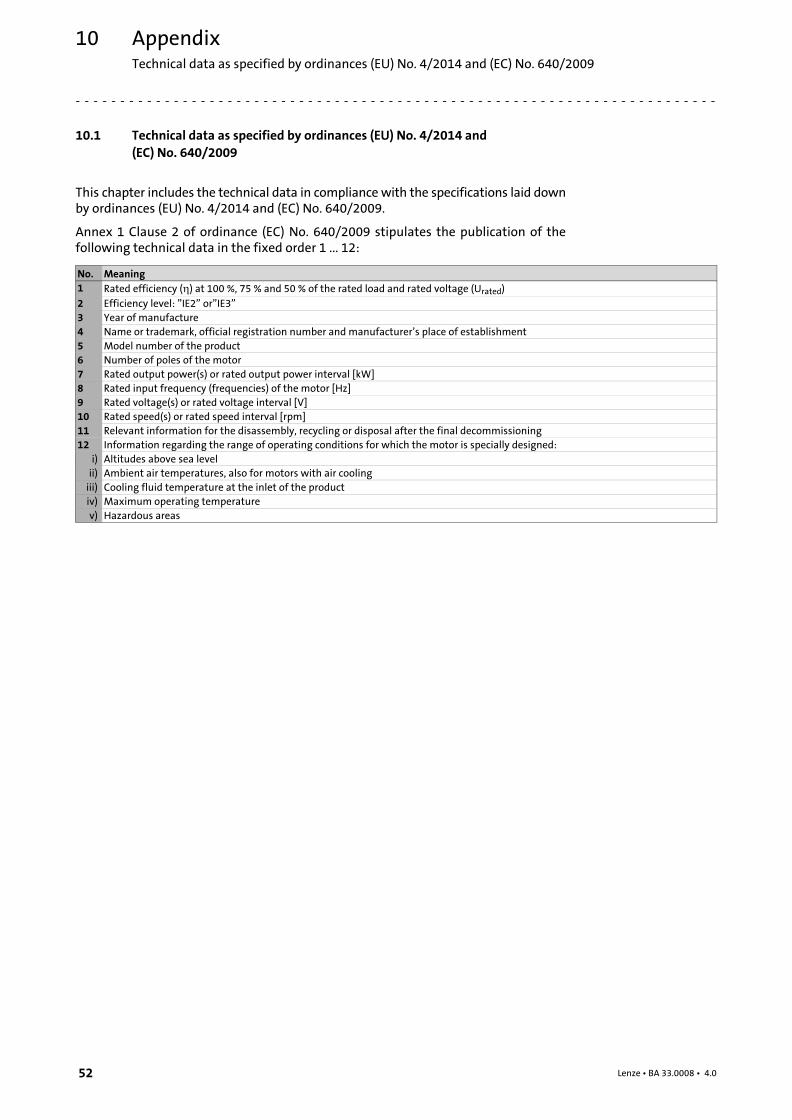
10 Appendix
10.1 Technical data as specified by ordinances (EU) No. 4/2014 and
(EC) No. 640/2009
This chapter includes the technical data in compliance with the specifications laid downby ordinances (EU) No. 4/2014 and (EC) No. 640/2009.
Annex 1 Clause 2 of ordinance (EC) No. 640/2009 stipulates the publication of thefollowing technical data in the fixed order 1 ... 12:
No. Meaning
1 Rated efficiency (�) at 100 %, 75 % and 50 % of the rated load and rated voltage (Urated)
2 Efficiency level: "IE2" or"IE3"
3 Year of manufacture
4 Name or trademark, official registration number and manufacturer’s place of establishment
5 Model number of the product
6 Number of poles of the motor
7 Rated output power(s) or rated output power interval [kW]
8 Rated input frequency (frequencies) of the motor [Hz]
9 Rated voltage(s) or rated voltage interval [V]
10 Rated speed(s) or rated speed interval [rpm]
11 Relevant information for the disassembly, recycling or disposal after the final decommissioning
12 Information regarding the range of operating conditions for which the motor is specially designed:
i) Altitudes above sea level
ii) Ambient air temperatures, also for motors with air cooling
iii) Cooling fluid temperature at the inlet of the product
iv) Maximum operating temperature
v) Hazardous areas
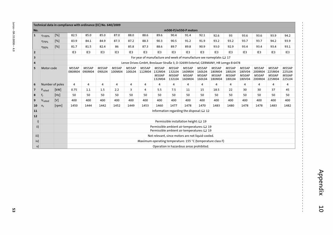
Ap
pen
dix
10 53
Lenze ¯ B
A 3
3.0
00
8 ¯ 4
.0
Technical data in compliance with ordinance (EC) No. 640/2009
No. m500−P/m550−P motors
1 �100% [%] 82.5 85.0 85.0 87.0 88.0 88.6 89.6 90.4 91.4 92.1 92.6 93 93.6 93.6 93.9 94.2
�75% [%] 83.9 84.1 84.9 87.3 87.2 88.3 90.3 90.5 91.2 91.9 93.2 93.2 93.7 93.7 94.2 93.9
�50% [%] 81.7 81.5 82.4 86 85.8 87.3 88.6 89.7 89.8 90.9 93.0 92.9 93.4 93.4 93.4 93.1
2 IE3 IE3 IE3 IE3 IE3 IE3 IE3 IE3 IE3 IE3 IE3 IE3 IE3 IE3 IE3 IE3
3 For year of manufacture and week of manufacture see nameplate: � 17
4 Lenze Drives GmbH, Breslauer Straße 3, D−32699 Extertal, GERMANY, HR Lemgo B 6478
5 Motor code M55AP080M04
M55AP090M04
M55AP090L04
M55AP100M04
M55AP100L04
M55AP112M04
M55AP132M04M50AP
132M04
M55AP132L04M50AP132L04
M55AP160M04M50AP
160M04
M55AP160L04M50AP160L04
M55AP180M04M50AP
180M04
M55AP180L04M50AP180L04
M55AP180V04M50AP180V04
M55AP200M04M50AP
200M04
M55AP225M04M50AP
225M04
M55AP225L04M50AP225L04
6 Number of poles 4 4 4 4 4 4 4 4 4 4 4 4 4 4 4 4
7 Prated [kW] 0.75 1.1 1.5 2.2 3 4 5.5 7.5 11 15 18.5 22 30 30 37 45
8 fr [Hz] 50 50 50 50 50 50 50 50 50 50 50 50 50 50 50 50
9 Vrated [V] 400 400 400 400 400 400 400 400 400 400 400 400 400 400 400 400
10 nr [rpm] 1450 1444 1442 1452 1449 1453 1460 1477 1478 1470 1483 1480 1478 1478 1483 1482
11 Information regarding the disposal: � 12
12
i) Permissible installation height: � 19
ii) Permissible ambient air temperatures: � 19Permissible ambient air temperatures: � 19
iii) Not relevant, since motors are not liquid−cooled.
iv) Maximum operating temperature: 155 C (temperature class F)
v) Operation in hazardous areas prohibited.
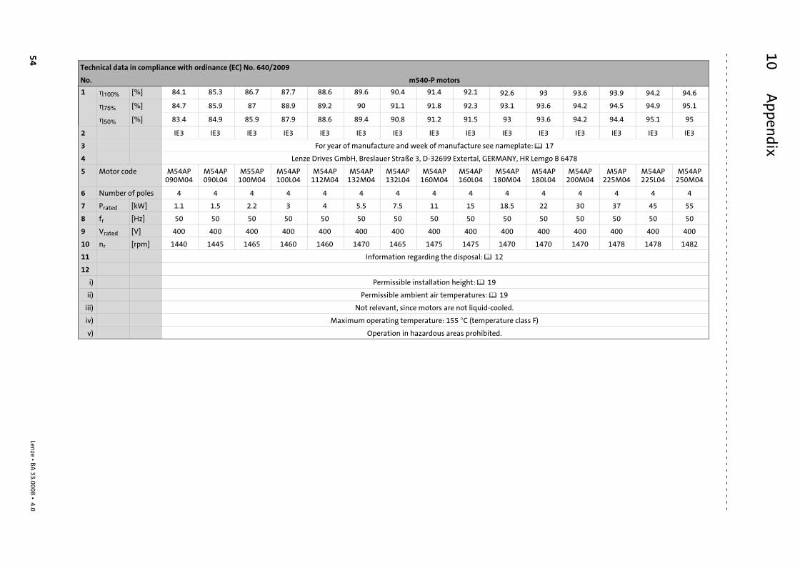
Ap
pen
dix
10
54
Lenze ¯ B
A 3
3.0
00
8 ¯ 4
.0
Technical data in compliance with ordinance (EC) No. 640/2009
No. m540−P motors
1 �100% [%] 84.1 85.3 86.7 87.7 88.6 89.6 90.4 91.4 92.1 92.6 93 93.6 93.9 94.2 94.6
�75% [%] 84.7 85.9 87 88.9 89.2 90 91.1 91.8 92.3 93.1 93.6 94.2 94.5 94.9 95.1
�50% [%] 83.4 84.9 85.9 87.9 88.6 89.4 90.8 91.2 91.5 93 93.6 94.2 94.4 95.1 95
2 IE3 IE3 IE3 IE3 IE3 IE3 IE3 IE3 IE3 IE3 IE3 IE3 IE3 IE3 IE3
3 For year of manufacture and week of manufacture see nameplate: � 17
4 Lenze Drives GmbH, Breslauer Straße 3, D−32699 Extertal, GERMANY, HR Lemgo B 6478
5 Motor code M54AP090M04
M54AP090L04
M55AP100M04
M54AP100L04
M54AP112M04
M54AP132M04
M54AP132L04
M54AP160M04
M54AP160L04
M54AP180M04
M54AP180L04
M54AP200M04
M5AP225M04
M54AP225L04
M54AP250M04
6 Number of poles 4 4 4 4 4 4 4 4 4 4 4 4 4 4 4
7 Prated [kW] 1.1 1.5 2.2 3 4 5.5 7.5 11 15 18.5 22 30 37 45 55
8 fr [Hz] 50 50 50 50 50 50 50 50 50 50 50 50 50 50 50
9 Vrated [V] 400 400 400 400 400 400 400 400 400 400 400 400 400 400 400
10 nr [rpm] 1440 1445 1465 1460 1460 1470 1465 1475 1475 1470 1470 1470 1478 1478 1482
11 Information regarding the disposal: � 12
12
i) Permissible installation height: � 19
ii) Permissible ambient air temperatures: � 19
iii) Not relevant, since motors are not liquid−cooled.
iv) Maximum operating temperature: 155 C (temperature class F)
v) Operation in hazardous areas prohibited.

Notes �
55Lenze ¯ BA 33.0008 ¯ 4.0
© 06/2017 | BA 33.0008 | .Vbo | 4.0 | TD09
Lenze Drives GmbHPostfach 10 13 52, 31763 HamelnBreslauer Straße 3, 32699 ExtertalGERMANYHR Lemgo B 6478
� +49�5154�82−0
� +49�5154�82−2800
� www.lenze.com
�
Lenze Service GmbHBreslauer Straße 3, D−32699 Extertal
Germany
� 0080002446877 (24 h helpline)
� +49�5154�82−1112
10 9 8 7 6 5 4 3 2 1
�