Operating instructions - Lutz-Jesco · Chlorine scrubber Operating instructions ... This operating...
36
Dosing Conveying Control Liquids Gases Systems Original operating instructions © Lutz-Jesco GmbH 2017 BA-27300-01-V07 Read the operating manual! The user is responsible for installation and operation related mistakes! Chlorine scrubber Operating instructions
Transcript of Operating instructions - Lutz-Jesco · Chlorine scrubber Operating instructions ... This operating...
DosingConveying
Control
Liquids
Gases
Systems
Original operating instructions
© Lutz-Jesco GmbH 2017
BA-27300-01-V07
Read the operating manual!
The user is responsible for installation and operation related mistakes!
Chlorine scrubberOperating instructions

Table of Contents 3© Lutz-Jesco GmbH 2017Subject to technical changes.170131
BA-27300-01-V07
Chlorine scrubber Operating instructions
Table of Contents1 Notes for the Reader ..........................................................4
1.1 General non-discrimination ......................................................41.2 Explanation of the signal words ................................................41.3 Explanation of the warning signs .............................................41.4 Identification of warnings .........................................................41.5 Instruction for action identification ...........................................4
2 Safety .................................................................................52.1 General warnings .....................................................................52.2 Information about chlorine .......................................................52.3 Hazards due to non-compliance with the safety instructions .....52.4 Working in a safety-conscious manner .....................................52.5 Personal protective equipment .................................................62.6 Personnel qualification .............................................................62.7 Personnel tasks .......................................................................6
3 Intended use ......................................................................73.1 Notes on product warranty .......................................................73.2 Intended purpose .....................................................................7
4 Product description ...........................................................84.1 Scope of delivery .....................................................................84.2 Design and function .................................................................8
5 Technical data ....................................................................95.1 Single-stage chlorine scrubber.................................................95.2 Two-stage chlorine scrubber ..................................................105.3 Temperature-stability caustic soda .........................................11
6 Dimensions ......................................................................126.1 Single-stage chlorine scrubber...............................................126.2 Two-stage chlorine scrubber ..................................................13
7 Installation .......................................................................147.1 Installation location ................................................................147.2 Hydraulic installations ............................................................147.3 Electrical installation ..............................................................147.4 Completing the installation .....................................................14
8 Start-up ............................................................................158.1 Control cabinet ......................................................................158.2 Check that the system is leaktight ..........................................158.3 Commissioning the device .....................................................16
9 Operation ..........................................................................179.1 Test intervals .........................................................................179.2 Simulating the release of chlorine gas ....................................17
10 Shutdown and disposal ...................................................1810.1 Shutdown ............................................................................1810.2 Disposal ..............................................................................18
11 Maintenance ....................................................................1911.1 Changing the NaOH solution .................................................1911.2 Removing deposits ..............................................................1911.3 Cleaning the spray nozzle .....................................................1911.4 Finishing maintenance .........................................................19
12 Troubleshooting ...............................................................20
13 System drawings .............................................................21
14 Switching diagrams .........................................................2614.1 Single-stage chlorine scrubber.............................................2614.2 Two-stage chlorine scrubber ................................................28
15 Declaration of no objection ..............................................30
16 Warranty claim .................................................................31
17 Index .................................................................................32
Notes for the ReaderGeneral non-discrimination
4 © Lutz-Jesco GmbH 2017BA-27300-01-V07
Chlorine scrubber Operating instructions
1 Notes for the Reader
This operating manual contains information and behaviour rules for the safe and designated operation of the device.
Observe the following principles:
nRead the entire operating manual prior to starting-up the device.nensure that everyone who works with or on the device has read the
operating manual and follows it.nMaintain the operating manual throughout the service life of the
device.nPass the operating manual on to any subsequent owner of the device.
1.1 General non-discriminationIn this operating manual, only the male gender is used where grammar allows gender allocation. The purpose of this is to make the text easy to read. Men and women are always referred to equally. We would like to ask female readers for understanding of this text simplification.
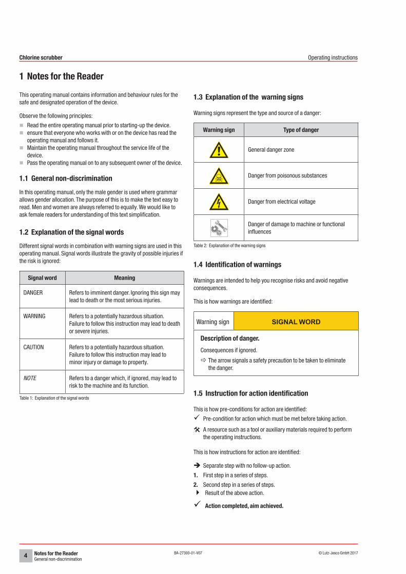
1.2 Explanation of the signal wordsDifferent signal words in combination with warning signs are used in this operating manual. Signal words illustrate the gravity of possible injuries if the risk is ignored:
Signal word Meaning
DANGER Refers to imminent danger. Ignoring this sign may lead to death or the most serious injuries.
WARNING Refers to a potentially hazardous situation. Failure to follow this instruction may lead to death or severe injuries.
CAUTION Refers to a potentially hazardous situation. Failure to follow this instruction may lead to minor injury or damage to property.
NOTE Refers to a danger which, if ignored, may lead to risk to the machine and its function.
Table 1: Explanation of the signal words
1.3 Explanation of the warning signs
Warning signs represent the type and source of a danger:
Warning sign Type of danger
General danger zone
Danger from poisonous substances
Danger from electrical voltage
Danger of damage to machine or functional influences
Table 2: Explanation of the warning signs
1.4 Identification of warnings
Warnings are intended to help you recognise risks and avoid negative consequences.
This is how warnings are identified:
Warning sign SIGNAL WORD
Description of danger.Consequences if ignored.
ðThe arrow signals a safety precaution to be taken to eliminate the danger.
1.5 Instruction for action identification
This is how pre-conditions for action are identified:
üPre-condition for action which must be met before taking action.
@A resource such as a tool or auxiliary materials required to perform the operating instructions.
This is how instructions for action are identified:
èSeparate step with no follow-up action.
1. First step in a series of steps.
2. Second step in a series of steps.4Result of the above action.
üAction completed, aim achieved.
SafetyGeneral warnings
5© Lutz-Jesco GmbH 2017Subject to technical changes.170131
BA-27300-01-V07
Chlorine scrubber Operating instructions
2 Safety
2.1 General warningsThe following warnings are intended to help you eliminate the dangers that can arise while handling the device. Risk prevention measures always apply regardless of any specific action.
Safety instructions warning against risks arising from specific activities or situations can be found in the respective sub-chapters.
DANGER
Danger to life from chlorine poisoning!Chlorine is poisonous. In severe cases, breathing in chlorine may lead to death. It irritates the eyes, the respiratory system and the skin.
ðUse sufficient personal protective equipment.
ðWhen carrying out any work on the system, use a respirator mask with a Type B gas filter that complies with EN 14387.
ðAlways comply with the accident prevention regulations that apply at the place of use.
ðGet rid of leaks without delay. You must get rid of even very minor leaks without delay.
ðUse only chlorine-resistant seals.
ðOnly use seals once. Reusing them leads to leaks.
DANGER
Danger to life from chlorine poisoning!Chlorinators without gas warning devices are an increased safety risk, since it is not possible to detect escaping chlorine gas in good time or at all.
ðInstall a gas warning device.
WARNING
Increased risk of accidents due to insufficient qualifica-tion of personnel!Chlorinators and their accessories must only be installed, operated and maintained by personnel with sufficient qualifications. Insufficient qualification will increase the risk of accidents.
ðEnsure that all action is taken only by personnel with sufficient and corresponding qualifications.
ðPrevent access to the system for unauthorised persons.
NOTE
Malfunctions from a blocked circulation pump or spray nozzlesThe neutralisation agent caustic soda (20% NaOH) is chemically stable at normal temperature conditions. If the minimum operating temperature (see section 5.3 „Temperature-stability caustic soda“ on page 11) is undercut, this will result in the development of crystals in the solution which can result in the blockage of the circulation pump and the spray nozzles.
ðIf it is possible that the minimum operating temperature could be undercut, install a heater.
ðDo not alter the concentration of the caustic soda The minimum operating temperature depends on the concentration.
2.2 Information about chlorineChlorine is a hazardous substance. The chemical element chlorine is a greenish-yellow, toxic gas with a pungent odour, which can be detected in the air at concentrations below 1 ppm (= 1 ml/m³).
Chlorine is 2.5 times heavier than air and accumulates at ground level.
Chlorine is extremely toxic for water organisms. The reason for the toxicity of chlorine is its extraordinary reactivity. It reacts with animal and vegetable tissue and thus destroys it.
Air with a chlorine gas content of 0.5 -1% leads to a quick death in mammals and humans, as it attacks the respiratory tract and the pulmonary alveolus (formation of hydrogen chloride or hydrochloride acid).
2.3 Hazards due to non-compliance with the safety instructions
Failure to follow the safety instructions may endanger not only persons, but also the environment and the device.
The specific consequences can be:
nfailure of important functions of the device and of the corresponding system,
nfailure of required maintenance and repair methods,ndanger to persons,ndanger to the environment caused by substances leaking from the
system.
2.4 Working in a safety-conscious manner
Besides the safety instructions specified in this operating manual, further safety rules apply and must be followed:
naccident prevention regulationsnsafety and operating provisions,nsafety regulations on handling hazardous substances,nenvironmental protection provisions,napplicable standards and legislation.
SafetyPersonal protective equipment
6 © Lutz-Jesco GmbH 2017BA-27300-01-V07
Chlorine scrubber Operating instructions
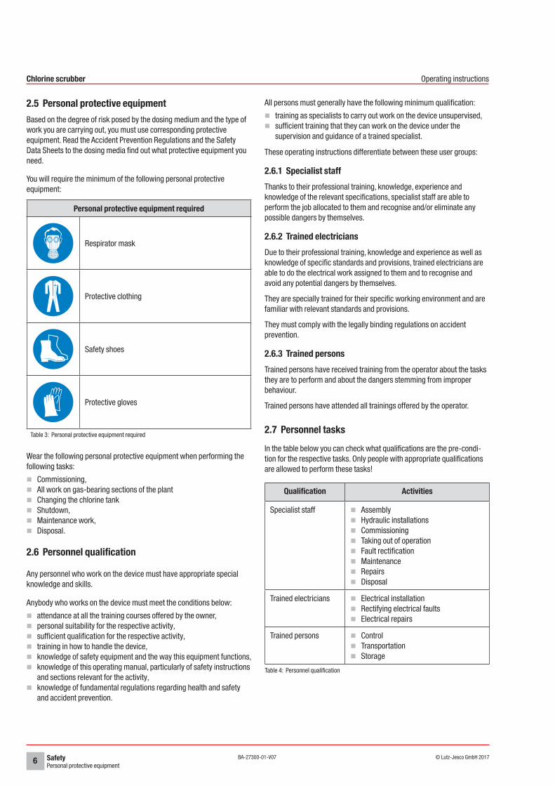
2.5 Personal protective equipmentBased on the degree of risk posed by the dosing medium and the type of work you are carrying out, you must use corresponding protective equipment. Read the Accident Prevention Regulations and the Safety Data Sheets to the dosing media find out what protective equipment you need.
You will require the minimum of the following personal protective equipment:
Personal protective equipment required
Respirator mask
Protective clothing
Safety shoes
Protective gloves
Table 3: Personal protective equipment required
Wear the following personal protective equipment when performing the following tasks:
nCommissioning,nAll work on gas-bearing sections of the plantnChanging the chlorine tanknShutdown,nMaintenance work,nDisposal.
2.6 Personnel qualification
Any personnel who work on the device must have appropriate special knowledge and skills.
Anybody who works on the device must meet the conditions below:
nattendance at all the training courses offered by the owner,npersonal suitability for the respective activity,nsufficient qualification for the respective activity,ntraining in how to handle the device,nknowledge of safety equipment and the way this equipment functions,nknowledge of this operating manual, particularly of safety instructions
and sections relevant for the activity,nknowledge of fundamental regulations regarding health and safety
and accident prevention.
All persons must generally have the following minimum qualification:
ntraining as specialists to carry out work on the device unsupervised,nsufficient training that they can work on the device under the
supervision and guidance of a trained specialist.
These operating instructions differentiate between these user groups:
2.6.1 Specialist staffThanks to their professional training, knowledge, experience and knowledge of the relevant specifications, specialist staff are able to perform the job allocated to them and recognise and/or eliminate any possible dangers by themselves.
2.6.2 Trained electriciansDue to their professional training, knowledge and experience as well as knowledge of specific standards and provisions, trained electricians are able to do the electrical work assigned to them and to recognise and avoid any potential dangers by themselves.
They are specially trained for their specific working environment and are familiar with relevant standards and provisions.
They must comply with the legally binding regulations on accident prevention.
2.6.3 Trained personsTrained persons have received training from the operator about the tasks they are to perform and about the dangers stemming from improper behaviour.
Trained persons have attended all trainings offered by the operator.
2.7 Personnel tasksIn the table below you can check what qualifications are the pre-condi-tion for the respective tasks. Only people with appropriate qualifications are allowed to perform these tasks!
Qualification Activities
Specialist staff nAssemblynHydraulic installationsnCommissioningnTaking out of operationnFault rectificationnMaintenancenRepairsnDisposal
Trained electricians nElectrical installationnRectifying electrical faultsnElectrical repairs
Trained persons nControlnTransportationnStorage
Table 4: Personnel qualification
Intended useNotes on product warranty
7© Lutz-Jesco GmbH 2017Subject to technical changes.170131
BA-27300-01-V07
Chlorine scrubber Operating instructions
3 Intended use
3.1 Notes on product warrantyAny non-designated use of the device can impair its function and the protection provided. This leads to invalidation of any warranty claims!
Please note that liability is on the side of the user in the following cases:
nThe device is operated in a manner which is not consistent with these operating instructions, particularly safety instructions, handling instructions and the section "Intended Use".
nInformation on usage and environment (see section 5 „Technical data“ on page 9) is not adhered to.
nif people operate the device who are not adequately qualified to carry out their respective activities.
nNo original spare parts or accessories of Lutz-Jesco GmbH are used.nUnauthorised changes are made to the device.nThe user uses different dosing media than those indicated in the
order.nMaintenance and inspection intervals are not adhered to as required
or not adhered to at all.nThe device is commissioned before it or the corresponding system
has been correctly and completely installed.nSafety equipment has been bridged, removed or made inoperative in
any other way.
3.2 Intended purposeThe chlorine scrubber is intended for the following purpose only: Extract ambient air in a room contaminated with chlorine gas in an absorption tower with an integrated caustic soda sprayer to clean the extracted air from chlorine gas and return it to the environment in an non-dangerous state.
Product descriptionScope of delivery
8 © Lutz-Jesco GmbH 2017BA-27300-01-V07
Chlorine scrubber Operating instructions
4 Product description
4.1 Scope of deliveryPlease compare the delivery note with the scope of delivery. The following items are part of the scope of delivery.
Version single-stage chlorine scrubber
nCirculation pump and suction ventilatornOptional: 1 additional circulation pumpnOptional: 1 circulation pump and 1 suction ventilator additionallynPriming aid for neutralisation agentnNeutralisation tower with spray nozzlenPiping for the circulation pump and suction ventilatornControl cabinetnOperating manuals
Version two-stage chlorine scrubber
nCirculation pump and suction ventilator additionallynOptional: 1 circulation pump and 1 suction ventilator additionallynPriming aid for neutralisation agentn2 neutralisation towers with spray nozzlenPiping for the circulation pump and suction ventilatornOperating manuals
4.2 Design and function
4.2.1 Design
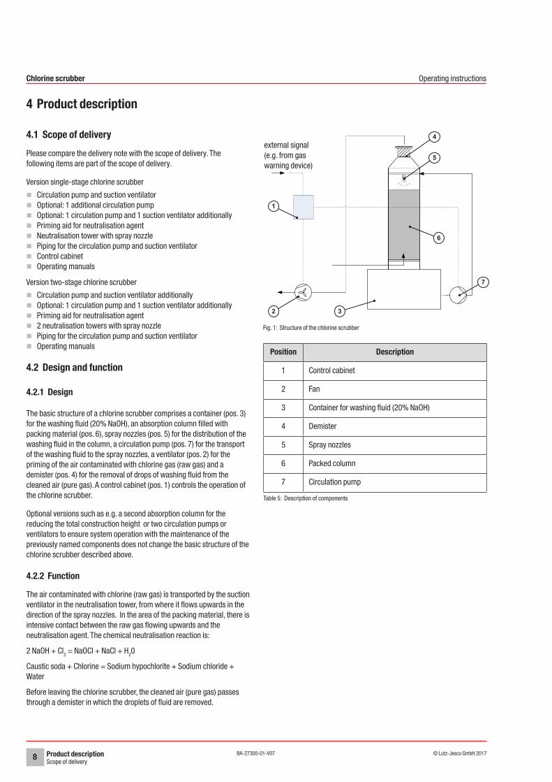
The basic structure of a chlorine scrubber comprises a container (pos. 3) for the washing fluid (20% NaOH), an absorption column filled with packing material (pos. 6), spray nozzles (pos. 5) for the distribution of the washing fluid in the column, a circulation pump (pos. 7) for the transport of the washing fluid to the spray nozzles, a ventilator (pos. 2) for the priming of the air contaminated with chlorine gas (raw gas) and a demister (pos. 4) for the removal of drops of washing fluid from the cleaned air (pure gas). A control cabinet (pos. 1) controls the operation of the chlorine scrubber.
Optional versions such as e.g. a second absorption column for the reducing the total construction height or two circulation pumps or ventilators to ensure system operation with the maintenance of the previously named components does not change the basic structure of the chlorine scrubber described above.
4.2.2 Function
The air contaminated with chlorine (raw gas) is transported by the suction ventilator in the neutralisation tower, from where it flows upwards in the direction of the spray nozzles. In the area of the packing material, there is intensive contact between the raw gas flowing upwards and the neutralisation agent. The chemical neutralisation reaction is:
2 NaOH + Cl2 = NaOCl + NaCl + H20
Caustic soda + Chlorine = Sodium hypochlorite + Sodium chloride + Water
Before leaving the chlorine scrubber, the cleaned air (pure gas) passes through a demister in which the droplets of fluid are removed.
Fig. 1: Structure of the chlorine scrubber
Position Description
1 Control cabinet
2 Fan
3 Container for washing fluid (20% NaOH)
4 Demister
5 Spray nozzles
6 Packed column
7 Circulation pump
Table 5: Description of components
3
7
5
6
1
2
4external signal (e.g. from gas warning device)
Technical dataSingle-stage chlorine scrubber
9© Lutz-Jesco GmbH 2017Subject to technical changes.170131
BA-27300-01-V07
Chlorine scrubber Operating instructions
5 Technical data
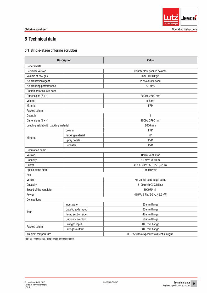
5.1 Single-stage chlorine scrubber
Description Value
General data
Scrubber version Counterflow packed column
Volume of raw gas max. 1000 kg/h
Neutralisation agent 20% caustic soda
Neutralising performance > 99 %
Container for caustic soda
Dimensions (Ø x H) 2000 x 2700 mm
Volume c. 8 m³
Material FRP
Packed column
Quantity 1
Dimensions (Ø x H) 1000 x 3760 mm
Loading height with packing material 2000 mm
Material
Column FRP
Packing material PP
Spray nozzle PVC
Demister PVC
Circulation pump
Version Radial ventilator
Capacity 10 m³/h @ 10 m
Power 415 V / 3 Ph / 50 Hz / 0,37 kW
Speed of the motor 2900 U/min
Fan
Version Horizontal centrifugal pump
Capacity 5100 m³/h @ 0,15 bar
Speed of the ventilator 3000 U/min
Power 415 V / 3 Ph / 50 Hz / 5,5 kW
Connections
Tank
Input water 25 mm flange
Caustic soda input 25 mm flange
Pump suction side 40 mm flange
Outflow / overflow 50 mm flange
Packed columnRaw gas input 400 mm flange
Pure gas output 400 mm flange
Ambient temperature 0 – 55°C (no exposure to direct sunlight)Table 6: Technical data - single-stage chlorine scrubber
Technical dataTwo-stage chlorine scrubber
10 © Lutz-Jesco GmbH 2017BA-27300-01-V07
Chlorine scrubber Operating instructions
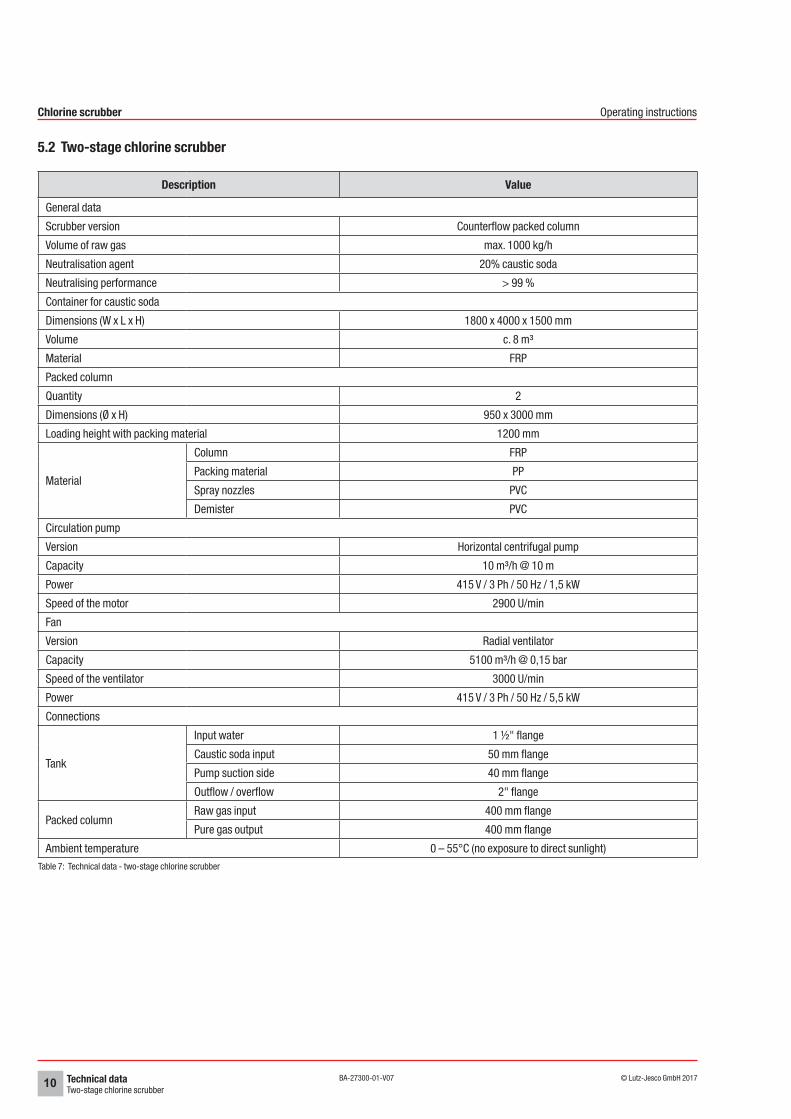
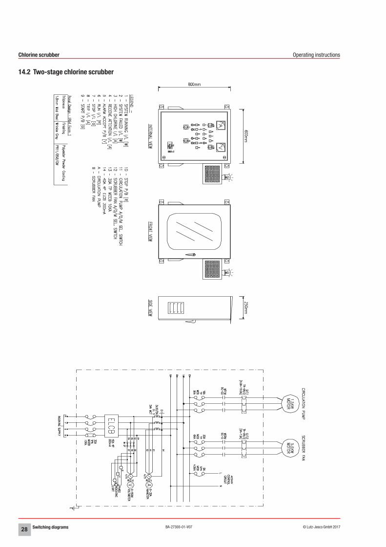
5.2 Two-stage chlorine scrubber
Description Value
General data
Scrubber version Counterflow packed column
Volume of raw gas max. 1000 kg/h
Neutralisation agent 20% caustic soda
Neutralising performance > 99 %
Container for caustic soda
Dimensions (W x L x H) 1800 x 4000 x 1500 mm
Volume c. 8 m³
Material FRP
Packed column
Quantity 2
Dimensions (Ø x H) 950 x 3000 mm
Loading height with packing material 1200 mm
Material
Column FRP
Packing material PP
Spray nozzles PVC
Demister PVC
Circulation pump
Version Horizontal centrifugal pump
Capacity 10 m³/h @ 10 m
Power 415 V / 3 Ph / 50 Hz / 1,5 kW
Speed of the motor 2900 U/min
Fan
Version Radial ventilator
Capacity 5100 m³/h @ 0,15 bar
Speed of the ventilator 3000 U/min
Power 415 V / 3 Ph / 50 Hz / 5,5 kW
Connections
Tank
Input water 1 ½" flange
Caustic soda input 50 mm flange
Pump suction side 40 mm flange
Outflow / overflow 2" flange
Packed columnRaw gas input 400 mm flange
Pure gas output 400 mm flange
Ambient temperature 0 – 55°C (no exposure to direct sunlight)Table 7: Technical data - two-stage chlorine scrubber
Technical dataTemperature-stability caustic soda
11© Lutz-Jesco GmbH 2017Subject to technical changes.170131
BA-27300-01-V07
Chlorine scrubber Operating instructions
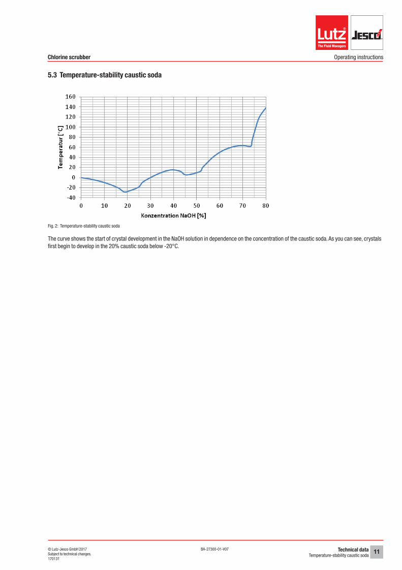
5.3 Temperature-stability caustic soda
Fig. 2: Temperature-stability caustic soda
The curve shows the start of crystal development in the NaOH solution in dependence on the concentration of the caustic soda. As you can see, crystals first begin to develop in the 20% caustic soda below -20°C.
DimensionsSingle-stage chlorine scrubber
12 © Lutz-Jesco GmbH 2017BA-27300-01-V07
Chlorine scrubber Operating instructions
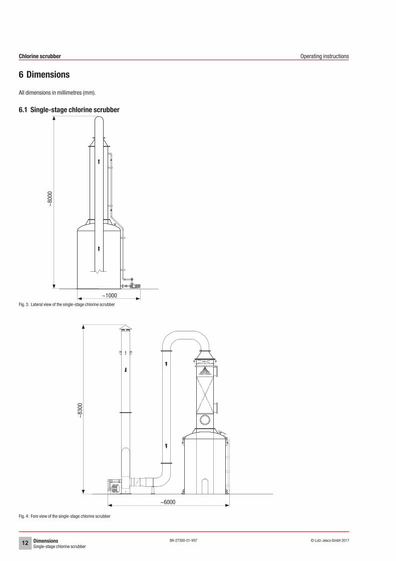
6 Dimensions
All dimensions in millimetres (mm).
6.1 Single-stage chlorine scrubber
Fig. 3: Lateral view of the single-stage chlorine scrubber
Fig. 4: Fore view of the single-stage chlorine scrubber
~80
00
~1000
~6000
~83
00
DimensionsTwo-stage chlorine scrubber
13© Lutz-Jesco GmbH 2017Subject to technical changes.170131
BA-27300-01-V07
Chlorine scrubber Operating instructions
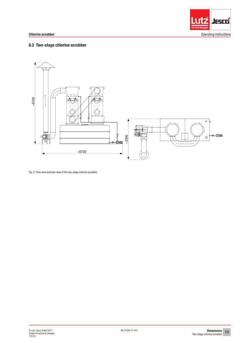
6.2 Two-stage chlorine scrubber
Fig. 5: Fore view and plan view of the two-stage chlorine scrubber
~6700
~67
00
~33
00
InstallationInstallation location
14 © Lutz-Jesco GmbH 2017BA-27300-01-V07
Chlorine scrubber Operating instructions
7 Installation
WARNING
Danger of personal injury and material damage!The system and its components are especially large and heavy. Comply with all safety measures during transportation and installation of the system in order to prevent injury and damage to property.
ðTransport the system parts with suitable lifting gear.
ðWear safety clothing whilst transporting the device.
ðNever transport the system or its components alone. It must be carried by min. two persons.
7.1 Installation locationnThe installation location must comply with the locally valid prescrip-
tionsnEnsure sufficient venting of the electric drive of the ventilator and the
pump at all times. nThe system must be accessible for operation, inspection and filling of
the NaOH container at all times.nSelect a level base for installation. The base must be able to support
the entire operating weight of the chlorine scrubber, the circulation pump and the ventilator and be able to absorb all types of vibration.
7.2 Hydraulic installations
The chlorine scrubber has been dismantled into its main parts for transport. Install the components at the installation location as shown in section 13 „System drawings“ on page 21.
As the only real difference between the one and two-stage scrubber is the second packed column, the description of the work steps for the installation of the scrubber does not differentiate between the two versions.
Pre-conditions for actions:
üThe device is located close to the concrete bas intended for installation.
Perform the following working steps:
1. Use suitable lifting gear to lift the NaOH container (1) onto the base using the two lifting lugs (2).
2. Secure it to the base using the three fastening clips (3). To this end, use suitable fixing devices (e.g. a bolt anchor) of sufficient length, to enable later levelling of the container (e.g. using washers).
3. Use suitable lifting gear to lift the packed column (4) at the lifting lugs (5) an. Place the packed column on the NaOH container and secure it.
4. Fit the circulation pump (6) on the base next to the container.
5. Install a pipe connection between the pump container connection flange (7) and the suction connection of the circulation pump. Install a ball valve in the pipe line (8). When using two circulation pumps, connect both pumps to the NaOH container via the pipe line and a T-piece. Instead of installing a ball valve in the pipe line to the NaOH container, install a ball valve in each pipe line to the T-piece.
6. Install a pipe connection (9) between the circulation pump and the spray nozzle (10) in the packed column. Install a ball valve in the pipe line (8).
7. Install a fill level display on the flanges (11 and 12) of the container.
8. Connect a fresh water inflow to the flange (13).
9. Install an overflow line on the flange (14) and an outflow line with stop valve on the flange (15).
i Comply with the manufacturer’s instructions when installing and connecting the circulation pump and ventilator.
üThe system has been hydraulically installed.
7.3 Electrical installation
Consult the respective operating manuals and the circuit diagram of the control cabinet for the exact procedure for the installation of the control cabinet and the connection of the pump and the ventilator to the control cabinet.
DANGER
Mortal danger from electric shock!Live parts can inflict fatal injuries.
ðDisconnect all electrical devices from the power supply before undertaking any work on the system.
ðSecure all electrical devices against being switched on by accident.
7.4 Completing the installationCheck all electrical connections after completing the installation. Check all hydraulic connections for leak-tightness.

Start-upControl cabinet
15© Lutz-Jesco GmbH 2017Subject to technical changes.170131
BA-27300-01-V07
Chlorine scrubber Operating instructions
8 Start-up
DANGER
Chlorine gas can escape due to systems that are leaky or not installed correctly!Chlorinators constitute an increased safety risk if they have not been properly installed, if an adequate leak test has not been performed or if the devices are not in good condition.
ðBefore placing the system into operation, have it checked by technical personnel to ensure that it is in the proper condition and leaktight.
ðThe condition of the installation must be checked for adequate tightness on a regular basis.
ðGet rid of leaks without delay. You must get rid of even very minor leaks without delay. Together with the humidity, chlorine forms hydrochloric acid and corrosion results in rapidly increasing leakage.
8.1 Control cabinet
i Fig. 6 "Control cabinet" Shows the fore-view of the control cabinet for a scrubber with a circulation pump and a ventilator. The applicable wiring diagrams are shown in section 14 „Switching diagrams“ on page 26.
Fig. 6: Control cabinet
Position Description
1 Display “System activated”
2 Display “Malfunction”
3 Display “Chlorine excess”
4 Display “Alarm”
Table 8: Control cabinet
Position Description
5 “Clear alarm” button
6 Display “Pump / ventilator in operation”
7 Display “Pump / ventilator not in operation”
8 Display “Pump / ventilator overload”
9 “Manual stop pump / ventilator” button
10 “Manual stop pump / ventilator” button
11 Operating mode selector “Pump (A/0/M)“
12 Operating mode selector “Ventilator (A/0/M)“
13 Display “Leakage”
14 Power switch
15 FI circuit breaker
Table 8: Control cabinet
8.2 Check that the system is leaktight
Precondition for action:
üAll of the scrubber components have been installed correctly.
üAll electrical connections have been established and checked.
üThe correct rotation direction of the circulation pump and the suction ventilator was checked.
üThe circulation pump and the suction ventilator have been anchored to the floor in a level fashion.
üThe operating mode selector of the pump (11) and the ventilator (12) are in the 0 position on the control cabinet.
üThe mains switch (14) and the FI circuit breaker (15) are in the off / 0 position on the control cabinet.
Perform the following working steps:
1. Fill the priming aid with clean water until the impeller of the circulation pump has been flooded.
2. Check the container, the piping, valves and connections up to the pump for leaks. No water should be permitted to escape.
3. Open the shutoff valve on the discharge side of the circulation pump.
4. Place the mains switch and the FI circuit breaker in the on or 1 position.
5. Set the operating mode selector for the circulation pump and the ventilator on the control cabinet to manual operation (M).
6. Start the pump and the ventilator via the two green buttons (9) lead the water in circulation for min. 1 hour and check the system for leaks and the operation of the pump and the ventilator.
Should you find leaks:
7. Stop pump and ventilator operation with the two red buttons (10).
Start-upCommissioning the device
16 © Lutz-Jesco GmbH 2017BA-27300-01-V07
Chlorine scrubber Operating instructions
8. Return the operating mode selector for the circulation pump and ventilator to the 0 position.
9. Close the shutoff valve of the container in the direction of the pump.
10. Repair the leak. Allow any adhesive surfaces to harden sufficiently and repeat the leak test.
If no leaks are found:
11. Stop pump operation via the red button (10) on the control cabinet.
12. Close the shutoff valve of the container in the direction of the pump.
13. Open the floor drain in the container and empty the container.
14. Stop the ventilator operation via the red button (10) on the control cabinet.
üThe system has been checked for leaks.
8.3 Commissioning the device
WARNING
Damage of the circulation pumpThe circulation pump may not be permitted to run dry.
ðMake sure that the impeller floods the pump before the pump is switched on.
Precondition for action:
üAfter it was installed, the system operated on a trial basis using water and air to ensure that it was able to prime ambient air and neutralisa-tion liquid.
Perform the following working steps:
1. Fill the priming aid with neutralisation agent to the marking on the inspection glass.
2. Open the shutoff valve on the container so that the impeller floods the pump with neutralisation agent.
3. Set the operating mode selector of the pump and ventilator to automatic operation (A).
üThe device is commissioned.
OperationTest intervals
17© Lutz-Jesco GmbH 2017Subject to technical changes.170131
BA-27300-01-V07
Chlorine scrubber Operating instructions
9 OperationIndividual operation is no longer necessary after the system has been put into automatic operation in the control cabinet. The system is monitored fully by the control program.
9.1 Test intervalsWe recommend regular inspections and function tests to ensure problem-free system operation.
Interval Test
daily nVisual inspection of the system
monthly nInspection of the washing fluid (min. 19% NaOH, pH value: 13 - 14) by a chemical laboratory
nCheck whether the system starts automatically in an alarm situation (simulation of chlorine release)
every 3 months nInspect the washing fluid container and spray nozzles for deposits and encrusta-tion.
annually nInspection of the electrical equipment by an electrician, especially the function of the safety equipment
nReplace the NaOH solution
Table 9: Maintenance information and maintenance intervals
i The inspection intervals and inspections to be performed on the pumps and the ventilators are listed in the operating manual of the respective devices.
9.2 Simulating the release of chlorine gas
The automatic start of the chlorine scrubber in an alarm situation can be checked by releasing a small quantity of chlorine gas in the vicinity of a chlorine sensor on the gas warning device. Chlorine gas generators (e.g. the chlorine test from Lutz-Jesco GmbH) provides a safe method to provide smaller quantities of chlorine gas. The quantity of chlorine generated by these devices (c. 5 ppm) can lie below the alarm threshold of the gas warning device so that under certain circumstances, it may be necessary to reduce the alarm threshold for the test.
Shutdown and disposalShutdown
18 © Lutz-Jesco GmbH 2017BA-27300-01-V07
Chlorine scrubber Operating instructions
10 Shutdown and disposal
10.1 ShutdownPerform the following working steps:
1. Stop automatic operation on the control cabinet.
2. Set the mains switch on the control cabinet to off.
üChlorine scrubber has been decommissioned.
10.2 Disposal
èClean the system before disposal. Unclean water may not be permitted to enter a domestic drain system.
èThe system and all chemicals used must be disposed of in accord-ance with applicable local laws and regulations. They should not be disposed of as domestic waste!
MaintenanceChanging the NaOH solution
19© Lutz-Jesco GmbH 2017Subject to technical changes.170131
BA-27300-01-V07
Chlorine scrubber Operating instructions
11 Maintenance
System maintenance is not required as long as the chlorine scrubber is operated correctly and the inspection intervals are maintained.
We urgently recommend that you replace the NaOH solution and clean the NaOH container after every alarm operation of the chlorine scrubber with chlorine release and after one year at the latest (see 11.1 "Changing the NaOH solution").
Any deposits which have accreted on the floor of the NaOH container, the spray nozzle or the packing material must be removed (see 11.2 "Remov-ing deposits" and 11.3 "Cleaning the spray nozzle").
11.1 Changing the NaOH solution
i The NaOH solution must be disposed of as dangerous waste in accordance with the local / regional / national / international specifications. The solution may not be permitted to enter a domestic drain system untreated.
Perform the following working steps:
1. Stop automatic system operation on the control cabinet.
2. Close the valve to the pump.
3. Open the drain valve on the container and dispose of the contents.
4. Close the drain valve.
5. Clean the tank interior (e.g. with a high-pressure cleaner) with hot water.
6. Open the drain valve on the container and dispose of the waste water.
7. Close the drain valve.
8. Fill the container with fresh NaOH solution.
üNaOH solution changed
11.2 Removing deposits
Pre-conditions for actions:
üCarry out steps 1 to 5 in section 11.1 "Changing the NaOH solution".
Perform the following working steps:
1. Fill the priming aid with a suitable detergent (e.g. 5% citric acid) until the impeller of the circulation pump has been flooded.
2. Open the valve to the pump.
3. Start the pump in manual operation and allow the detergent to circulate in the chlorine scrubber for a short time.
4. Stop pump operation.
5. Close the valve to the pump.
6. Open the drain valve and dispose of the detergent.
7. Close the drain valve.
8. Fill the container with fresh NaOH solution.
üDeposits have been removed
11.3 Cleaning the spray nozzleGiven strong deposits on the spray nozzle or the blockage of a spray nozzle remove and clean the spray nozzle from the spray head and.
Perform the following working steps:
1. Stop automatic system operation on the control cabinet.
2. Open the inspection hatch on the height of the spray head.
3. Dismantle the blocked spray nozzle from the spray head.
4. Clean the spray nozzle mechanically or with a suitable detergent (e.g. 5% citric acid).
5. Rinse the spray nozzle with warm water.
6. Return the spray nozzle onto the spray head and close the inspection port.
üSpray nozzle cleaned
11.4 Finishing maintenance
Perform the following working steps:
1. Make a note of the date and scope of the maintenance performed.
2. Attach a sticker displaying the maintenance date to the device.
3. To restart the system, proceed in accordance with the instructions in section 8 „Start-up“ on page 15.
üMaintenance completed
Troubleshooting20 © Lutz-Jesco GmbH 2017BA-27300-01-V07
Chlorine scrubber Operating instructions
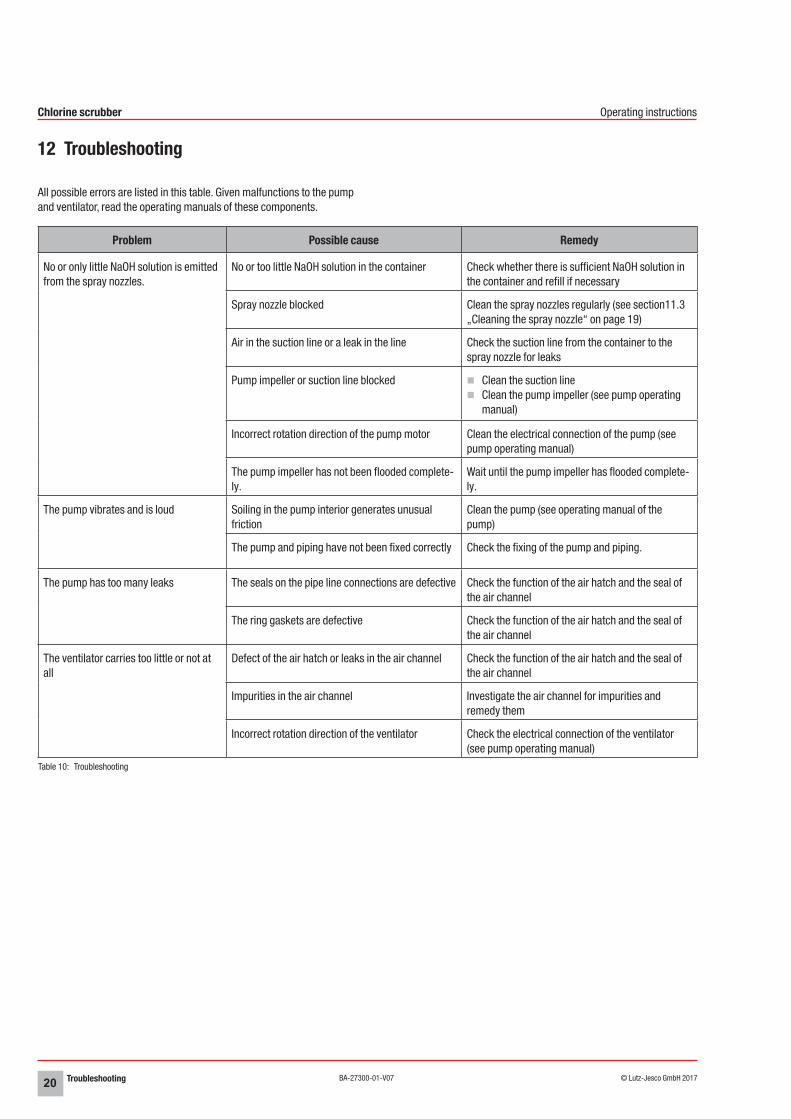
12 Troubleshooting
All possible errors are listed in this table. Given malfunctions to the pump and ventilator, read the operating manuals of these components.
Problem Possible cause Remedy
No or only little NaOH solution is emitted from the spray nozzles.
No or too little NaOH solution in the container Check whether there is sufficient NaOH solution in the container and refill if necessary
Spray nozzle blocked Clean the spray nozzles regularly (see section11.3 „Cleaning the spray nozzle“ on page 19)
Air in the suction line or a leak in the line Check the suction line from the container to the spray nozzle for leaks
Pump impeller or suction line blocked nClean the suction linenClean the pump impeller (see pump operating
manual)
Incorrect rotation direction of the pump motor Clean the electrical connection of the pump (see pump operating manual)
The pump impeller has not been flooded complete-ly.
Wait until the pump impeller has flooded complete-ly.
The pump vibrates and is loud Soiling in the pump interior generates unusual friction
Clean the pump (see operating manual of the pump)
The pump and piping have not been fixed correctly Check the fixing of the pump and piping.
The pump has too many leaks The seals on the pipe line connections are defective Check the function of the air hatch and the seal of the air channel
The ring gaskets are defective Check the function of the air hatch and the seal of the air channel
The ventilator carries too little or not at all
Defect of the air hatch or leaks in the air channel Check the function of the air hatch and the seal of the air channel
Impurities in the air channel Investigate the air channel for impurities and remedy them
Incorrect rotation direction of the ventilator Check the electrical connection of the ventilator (see pump operating manual)
Table 10: Troubleshooting
System drawings 21© Lutz-Jesco GmbH 2017Subject to technical changes.170131
BA-27300-01-V07
Chlorine scrubber Operating instructions
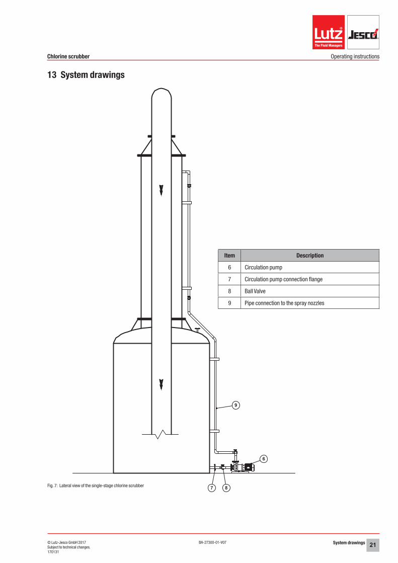
13 System drawings
6
7 8
9
Fig. 7: Lateral view of the single-stage chlorine scrubber
Item Description
6 Circulation pump
7 Circulation pump connection flange
8 Ball Valve
9 Pipe connection to the spray nozzles
System drawings22 © Lutz-Jesco GmbH 2017BA-27300-01-V07
Chlorine scrubber Operating instructions
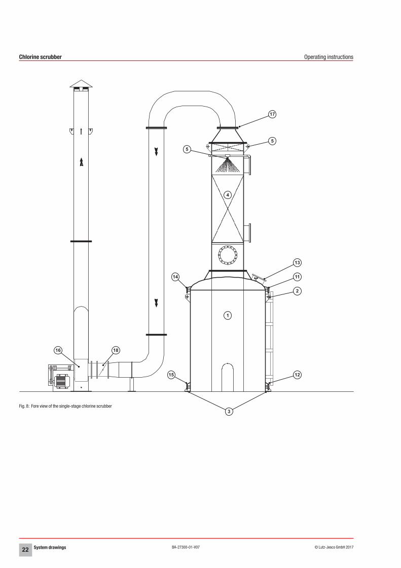
Fig. 8: Fore view of the single-stage chlorine scrubber
1
4
17
5
5
13
11
2
12
3
15
14
1816

System drawings 23© Lutz-Jesco GmbH 2017Subject to technical changes.170131
BA-27300-01-V07
Chlorine scrubber Operating instructions
Item Description
1 Container (NaOH)
2 Container lifting lugs
3 Container fastening clip
4 Packed column
5 Packed column lifting lugs
10 Spray nozzles
11 Upper flange of the fill level display
12 Lower flange of the fill level display
13 Input water flange
14 Flange overflow
15 Outflow flange
16 Fan
17 Air outlet flange
18 Ventilation flap
System drawings24 © Lutz-Jesco GmbH 2017BA-27300-01-V07
Chlorine scrubber Operating instructions
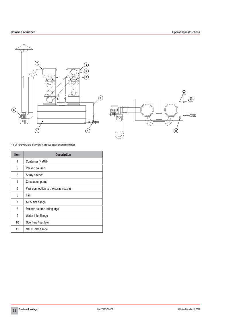
Fig. 9: Fore view and plan view of the two-stage chlorine scrubber
Item Description
1 Container (NaOH)
2 Packed column
3 Spray nozzles
4 Circulation pump
5 Pipe connection to the spray nozzles
6 Fan
7 Air outlet flange
8 Packed column lifting lugs
9 Water inlet flange
10 Overflow / outflow
11 NaOH inlet flange
2
9
10
11
6
1 4
5
3
87
System drawings 25© Lutz-Jesco GmbH 2017Subject to technical changes.170131
BA-27300-01-V07
Chlorine scrubber Operating instructions
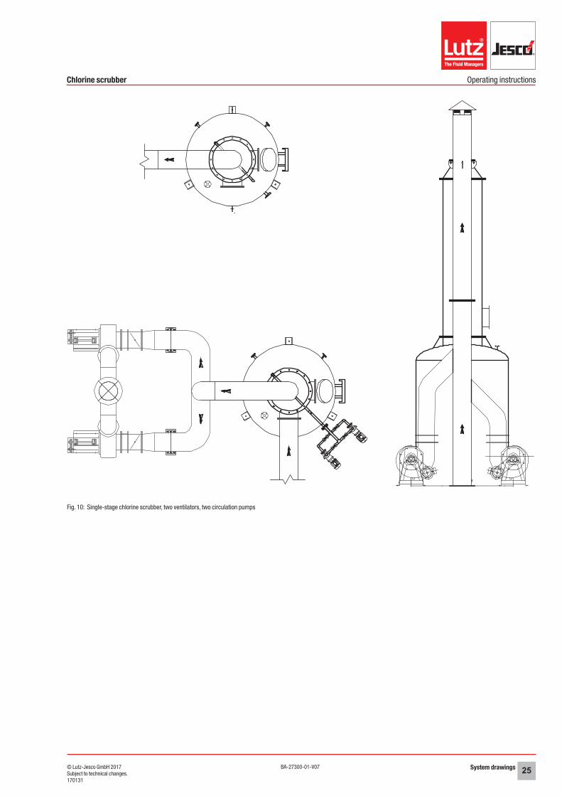
Fig. 10: Single-stage chlorine scrubber, two ventilators, two circulation pumps
Switching diagrams26 © Lutz-Jesco GmbH 2017BA-27300-01-V07
Chlorine scrubber Operating instructions
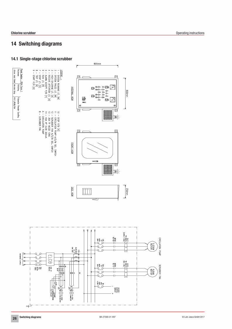
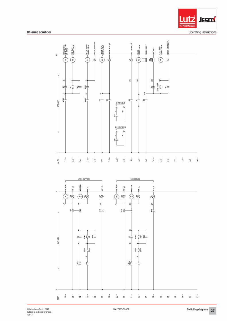
14 Switching diagrams
14.1 Single-stage chlorine scrubber
Switching diagrams 27© Lutz-Jesco GmbH 2017Subject to technical changes.170131
BA-27300-01-V07
Chlorine scrubber Operating instructions
Switching diagrams28 © Lutz-Jesco GmbH 2017BA-27300-01-V07
Chlorine scrubber Operating instructions
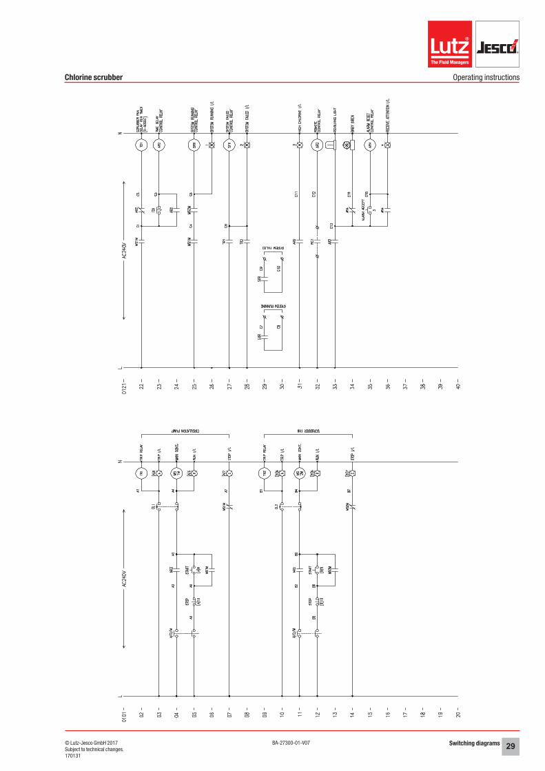
14.2 Two-stage chlorine scrubber
Switching diagrams 29© Lutz-Jesco GmbH 2017Subject to technical changes.170131
BA-27300-01-V07
Chlorine scrubber Operating instructions
Declaration of no objection30 © Lutz-Jesco GmbH 2017BA-27300-01-V07
Chlorine scrubber Operating instructions
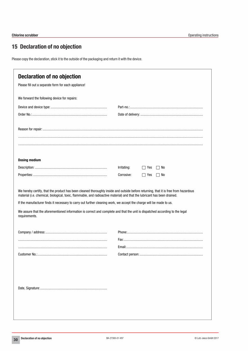
15 Declaration of no objection
Please copy the declaration, stick it to the outside of the packaging and return it with the device.
Declaration of no objectionPlease fill out a separate form for each appliance!
We forward the following device for repairs:
Device and device type: ................................................................ Part-no.:...................................................................................
Order No.: ..................................................................................... Date of delivery: .......................................................................
Reason for repair: ......................................................................................................................................................................................
..................................................................................................................................................................................................................
..................................................................................................................................................................................................................
Dosing medium
Description: .................................................................................. Irritating: Yes No
Properties: .................................................................................... Corrosive: Yes No
We hereby certify, that the product has been cleaned thoroughly inside and outside before returning, that it is free from hazardous material (i.e. chemical, biological, toxic, flammable, and radioactive material) and that the lubricant has been drained.
If the manufacturer finds it necessary to carry out further cleaning work, we accept the charge will be made to us.
We assure that the aforementioned information is correct and complete and that the unit is dispatched according to the legal requirements.
Company / address:...................................................................... Phone:......................................................................................
..................................................................................................... Fax:..........................................................................................
..................................................................................................... Email:.......................................................................................
Customer No.:............................................................................... Contact person: ........................................................................
Date, Signature:............................................................................
Warranty claim 31© Lutz-Jesco GmbH 2017Subject to technical changes.170131
BA-27300-01-V07
Chlorine scrubber Operating instructions
16 Warranty claim
Warranty claimPlease copy and send it back with the unit!
If the device breaks down within the period of warranty, please return it in a cleaned condition with the complete warranty claim.
Sender
Company: ............................................................................................................... Phone: .................................. Date: ..........................
Address: ....................................................................................................................................................................................................
Contact person: .........................................................................................................................................................................................
Manufacturer order no.: .......................................................................................... Date of delivery: .........................................................
Device type: ............................................................................................................ Serial number: ...........................................................
Nominal capacity / nominal pressure: .........................................................................................................................................................
Description of fault:.....................................................................................................................................................................................
...................................................................................................................................................................................................................
...................................................................................................................................................................................................................
...................................................................................................................................................................................................................
...................................................................................................................................................................................................................
...................................................................................................................................................................................................................
...................................................................................................................................................................................................................
...................................................................................................................................................................................................................
Service conditions of the devicePoint of use / system designation:...............................................................................................................................................................
...................................................................................................................................................................................................................
...................................................................................................................................................................................................................
Accessories used (suction line etc.):............................................................................................................................................................
...................................................................................................................................................................................................................
...................................................................................................................................................................................................................
...................................................................................................................................................................................................................
...................................................................................................................................................................................................................
Commissioning (date): ................................................................................................................................................................................
Duty period (approx. operating hours): ........................................................................................................................................................
Please describe the specific installation and enclose a simple drawing or picture of the chemical feed system, showing materials of const-ruction, diameters, lengths and heights of suction and discharge lines.
Index32 © Lutz-Jesco GmbH 2017BA-27300-01-V07
Chlorine scrubber Operating instructions
17 Index
CCommissioning the device ...............................................................16Completing the installation ...............................................................14Control cabinet ..................................................................................9
DDimensioned drawings ....................................................................12Dimensions ......................................................................................12
EElectrical installation ........................................................................14
FFinishing maintenance .....................................................................19
GGeneral warnings ...............................................................................5
HHandling instructions
Marking ........................................................................................4Hazards due to non-compliance with the safety instructions ..............5Hydraulic installations ......................................................................14
IInformation about chlorine .................................................................5Installation .......................................................................................14
electrical ....................................................................................14hydraulic ....................................................................................14
Intended purpose ...............................................................................7Intended use ......................................................................................7
MMaintenance ....................................................................................19
Finishing .....................................................................................19
NNotes for the Reader ..........................................................................4
OOperation .........................................................................................17
PPersonal protective equipment ...........................................................6Personnel qualification .......................................................................6Personnel tasks .................................................................................6Product description ............................................................................8Product warranty ...............................................................................7
SSafety ................................................................................................5Scope of delivery ...............................................................................8
Shutdown ........................................................................................19Signal words
Explanation ...................................................................................4Specialist staff ...................................................................................6Start-up ...........................................................................................15Structure of the device .......................................................................8
TTechnical data ...................................................................................9Test intervals ...................................................................................17Trained electricians ............................................................................6Trained persons .................................................................................6
WWarnings
General warnings .........................................................................5Marking ........................................................................................4
Warning signExplanation ...................................................................................4
Warranty claim ................................................................................31Working in a safety-conscious manner ..............................................5
Index 33© Lutz-Jesco GmbH 2017Subject to technical changes.170131
BA-27300-01-V07
Chlorine scrubber Operating instructions


HeadquartersLutz-Jesco GmbHAm Bostelberge 1930900 WedemarkGermany
Tel.: +49 5130 5802-0Fax: +49 5130 580268
E-mail: [email protected]: www.lutz-jesco.de
NetherlandsLutz-Jesco Nederland B.V.Nijverheidstraat 14 C2984 AH RidderkerkNetherlands
Tel.: +31 180 499460Fax: +31 180 497516
E-mail: [email protected]: www.lutz-jesco.nl
HungaryLutz-Jesco ÜzletágVasvári P. u. 9.9024 GyörHungary
Tel.: +36 96 419813Fax: +36 96 419814
E-mail: [email protected]: www.lutz-jesco.hu
USALutz-JESCO America Corp.55 Bermar ParkRochester, N.Y. 14624USA
Tel.: +1 585 426-0990Fax: +1 585 426-4025
E-mail: [email protected]: www.lutzjescoamerica.com
East AsiaLutz-Jesco East Asia Sdn Bhd6 Jalan Saudagar U1/16Hicom Glenmarie Industrial Park40150 Shah Alam/ SelangorMalaysia
Tel.: +603 55692322Fax: +603 55691322
E-mail: [email protected]: www.lutz-jescoasia.com
AustriaLutz-Jesco GmbHAredstraße 7/22544 LeobersdorfAustria
Tel.: +43 2256 62180Fax: +43 2256 6218062
E-mail: [email protected]: www.lutz-jesco.at
Middle EastLutz-Jesco Middle East FZEP.O. Box 9614SAIF-Free Zone CenterSharjahUAE
Tel.: +971 6 5572205Fax: +971 6 5572230
E-mail: [email protected]: www.jescome.com
Great BritiainLutz-Jesco (GB) Ltd.Gateway EstateWest Midlands FreeportBirmingham B26 3QDGreat Britain
Tel.: +44 121 782 2662Fax: +44 121 782 2680
E-mail: [email protected]: www.lutz-jesco.co.uk
Product Range
Lutz Pumpen GmbHP.O. Box 1462 • D-97864 Wertheimwww.lutz-pumpen.com
Product Range
Lutz-Jesco GmbHP.O. Box 100164 • D-30891 Wedemarkwww.lutz-jesco.com
Centrifugal Pumps Products for the disinfection of swimming pool water based on salt water electrolysis and domestic water technology
The Lutz-Jesco App for iPads and iPhones is available from the iTunes App Store. Additional information can be found at www.lutz-jesco.com
Barrel and Container Pumps Dosing PumpsMeasuring and Control Equipment
Double Diaphragm Pumps Standard PlusChemical Centrifugal Pumps
Flow Meters Chlorinators Disinfection