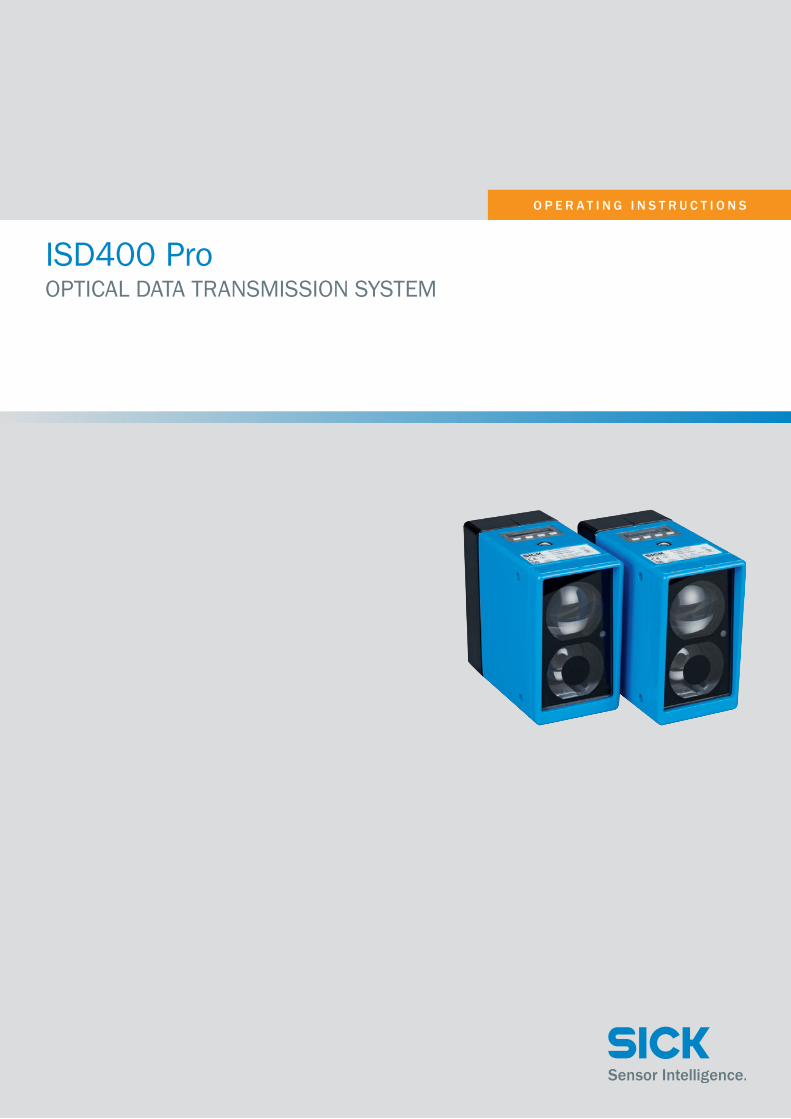
OPERATING INSTRUCTIONS ISD400 Pro - SICK
50
OPERATING INSTRUCTIONS ISD400 Pro OPTICAL DATA TRANSMISSION SYSTEM
Transcript of OPERATING INSTRUCTIONS ISD400 Pro - SICK
O P E R A T I N G I N S T R U C T I O N S
ISD400 Pro OPTICAL DATA TRANSMISSION SYSTEM

2 © SICK AG • Subject to change without notice • 8016441/15BT/2019-09
Described product
ISD400 Pro
Manufacturer
SICK AG
Erwin-Sick-Str. 1
79183 Waldkirch
Germany
Copyright
This work is protected by copyright. Any rights derived from the copyright shall be reserved for SICK AG. Repro-duction of this document or parts of this document is only permissible within the limits of the legal determination of Copyright Law. Any modification, expurgation or translation of this document is prohibited without the express written permission of SICK AG.
© SICK AG. All rights reserved.
Original document
This document is an original document of SICK AG.
- For use in NFPA79 applications only.- UL-Listed adapters providing field wiring leads are available.- Refer to the product information.E336916

8016441/15BT/2019-09 • © SICK AG • Subject to change without notice 3
Table of contents
Table of contents1 General information ........................................................................... 7
1.1 Information regarding the operating instructions ....................7
1.2 Explanation of symbols .............................................................7
1.3 Limitation of liability ..................................................................8
1.4 Scope of delivery .......................................................................8
1.5 Customer service .......................................................................8
1.6 EC declaration of conformity .....................................................9
2 Safety ................................................................................................ 10
2.1 Correct use .............................................................................. 10
2.2 Incorrect use ........................................................................... 10
2.3 Requirements for skilled persons and operating personnel 11
2.4 Operational safety and particular hazards .......................... 11
2.5 Warning symbol on the device ............................................... 12
2.6 Hazard warnings and operational safety .............................. 13
3 Product description ......................................................................... 15
3.1 Identification ........................................................................... 15
3.1.1 Type label................................................................. 15
3.1.2 Type overview .......................................................... 15
3.2 Structure and function ........................................................... 16
3.2.1 Structure and status indicators ............................. 16
3.2.2 Function ................................................................... 18
4 Transport and storage ..................................................................... 19
4.1 Transport ................................................................................. 19
4.2 Transport inspection ............................................................... 19
4.3 Storage .................................................................................... 20
5 Mounting .......................................................................................... 21
5.1 Mounting procedure ............................................................... 21
5.2 Mounting instructions ............................................................ 21
5.3 Arranging multiple optical devices ........................................ 22
5.4 Mounting the ISD400 Pro ...................................................... 24
6 Electrical connection ..................................................................... 26

Table of contents
4 © SICK AG • Subject to change without notice • 8016441/15BT/2019-09
6.1 Safety ....................................................................................... 26
6.2 Wiring notes ............................................................................ 26
6.3 Connecting the ISD400 Pro electrically ................................ 28
6.4 Connection diagrams ............................................................. 29
7 Commissioning ................................................................................ 31
7.1 Aligning the ISD400 Pro ......................................................... 31
8 Operating the device ....................................................................... 32
8.1 Displaying the received signal level ....................................... 32
8.2 Selecting parameters ............................................................. 32
8.3 Selecting options .................................................................... 32
8.4 Changing the value ................................................................. 33
8.5 Parameter description ............................................................ 34
8.5.1 Operating mode ...................................................... 34
8.5.2 Menu mode ............................................................. 35
8.6 Performing a reset .................................................................. 39
9 Cleaning and maintenance ............................................................. 40
9.1 Cleaning .................................................................................. 40
9.2 Maintenance ........................................................................... 40
10 Troubleshooting ............................................................................... 41
10.1 Warning messages ................................................................. 41
10.2 Error messages ....................................................................... 41
10.3 Possible error indicators ........................................................ 42
10.4 Disposal ................................................................................... 42
11 Technical data .................................................................................. 43
11.1 Dimensions ............................................................................. 43
11.2 Performance data ................................................................... 44
11.3 Power supply ........................................................................... 44
11.4 Interfaces ................................................................................ 44
11.5 Ambient conditions ................................................................. 45
11.6 Structural design .................................................................... 45
12 Accessories ...................................................................................... 46
12.1 Supply cable ............................................................................ 46

8016441/15BT/2019-09 • © SICK AG • Subject to change without notice 5
Table of contents
12.2 Ethernet cable ......................................................................... 46
12.3 Alignment bracket ................................................................... 46
13 Menu structure................................................................................. 47
Index .......................................................................................................... 49

6 © SICK AG • Subject to change without notice • 8016441/15BT/2019-09
8016441/15BT/2019-09 • © SICK AG • Subject to change without notice 7
General information
1 General information
1.1 Information regarding the operating instructions
These operating instructions supplement the Quick start guide and contain additional information and detailed descriptions for using the ISD400 Pro optical data transmission system from SICK AG. These operating instruc-tions are intended for skilled persons and electricians.
1.2 Explanation of symbols
Warnings Warnings in these operating instructions are indicated by symbols. The war-nings are introduced by signal words that indicate the extent of the danger.
These warnings must be observed at all times and care must be taken to avoid accidents, personal injury, and material damage.
DANGER
… indicates a situation of imminent danger, which will lead to a fatality or serious injuries if not prevented.
WARNING
… indicates a potentially dangerous situation, which may lead to a fatality or serious injuries if not prevented.
CAUTION
… indicates a potentially dangerous situation, which may lead to minor/slight injuries if not prevented.
NOTICE
… indicates a potentially harmful situation, which may lead to material damage if not prevented.

General information
8 © SICK AG • Subject to change without notice • 8016441/15BT/2019-09
Tips and recommendationsNOTE
… highlights useful tips and recommendations as well as information for efficient and trouble-free operation.
1.3 Limitation of liability
Applicable standards and regulations, the latest state of technological development, and many years of knowledge and experience have all been taken into account when assembling the data and information contained in these operating instructions.
The manufacturer accepts no liability for damage caused by:
• Failing to observe the operating instructions
• Incorrect use
• Use by untrained personnel
• Unauthorized conversions
• Technical modifications
• Use of unauthorized spare parts/consumable parts.
With special variants, where optional extras have been ordered, or owing to the latest technical changes, the actual scope of delivery may vary from the features and illustrations shown here.
1.4 Scope of delivery
The scope of delivery includes the following:
• ISD400 Pro optical data transmission system
• Optional: Accessories (→ Page 46, Chapter 12).
Supplied documentation:
• Quick start guide
1.5 Customer service
Do not hesitate to contact our customer service should you require any technical information.
A list of representatives can be found on the back page.
NOTE
Before calling, make a note of all type label data such as type code, serial number, etc. to ensure faster proces-sing.

8016441/15BT/2019-09 • © SICK AG • Subject to change without notice 9
General information
1.6 EC declaration of conformity
→ You can download the EC declaration of conformity online from "www.sick.com/isd400_pro".

Safety
10 © SICK AG • Subject to change without notice • 8016441/15BT/2019-09
2 Safety
2.1 Correct use
The ISD400 Pro data transmission system consists of two optically aligned devices, one of which functions as a sender and the other as a receiver. The devices communicate over long distances and support wireless data transmission.
Setting up a data transmission line requires a pair of devices, where one device, F1 (ISD400-7xx1), has a red sender and another device, F2 (ISD400-7xx2), has an infrared sender.
SICK AG assumes no liability for losses or damage arising from the use of the product, either directly or indirectly. This applies in particular to use of the product that does not conform to its intended purpose and is neither described nor mentioned in this documentation.
2.2 Incorrect use
The ISD400 Pro optical data transmission system does not constitute a safety component according to the EC Machinery Directive (2006/42/EC).
The ISD400 Pro optical data transmission system must not be used in explosion areas.
Any other use that is not described as correct use is prohibited.
Never install or connect accessories if their quantity and composition are not clearly specified, or if they have not been approved by SICK AG.

8016441/15BT/2019-09 • © SICK AG • Subject to change without notice 11
Safety
2.3 Requirements for skilled persons and operating personnel
WARNING
Risk of injury due to insufficient training.
Improper handling may result in considerable personal injury and material damage.
For this reason:
• All activities should always be performed by designa-ted persons only.
These operating instructions list the training requirements for the various fields of activity, as follows:
• Skilled personnel Due to their specialist training, skills, and experience, as well as their knowledge of the relevant regulations, such persons are able to perform tasks delegated to them and detect any potential dangers independent-ly.
• Electricians Due to their specialist training, skills, and experience, as well as their knowledge of the relevant standards and provisions, such persons are able to perform work on electrical systems and detect any potential dangers independently. In Germany, electricians must meet the specifications of the BGV A3 Work Safety Regulations (e.g. Master Electrician). Other relevant regula-tions applicable in other countries must be observed.
2.4 Operational safety and particular hazards
Please observe the safety notes and the warnings listed here and in other chapters of these operating instructions to reduce the possibility of risks to health and avoid dangerous situations.
Safety
12 © SICK AG • Subject to change without notice • 8016441/15BT/2019-09
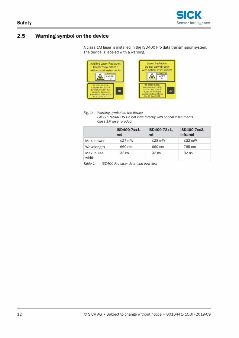
2.5 Warning symbol on the device
A class 1M laser is installed in the ISD400 Pro data transmission system. The device is labeled with a warning.
LASER1M
CAUTION
LASER1M
CAUTION
Fig. 1: Warning symbol on the device LASER RADIATION Do not view directly with optical instruments. Class 1M laser product
ISD400-7xx1, red
ISD400-73x1, rot
ISD400-7xx2, infrared
Max. power ≤27 mW ≤28 mW ≤32 mW
Wavelength 660 nm 660 nm 785 nm
Max. pulse width
32 ns 32 ns 32 ns
Table 1: ISD400 Pro laser data type overview

8016441/15BT/2019-09 • © SICK AG • Subject to change without notice 13
Safety
2.6 Hazard warnings and operational safety
Laser beam For your own safety, please read and observe the following notes:
WARNING
Risk of injury from laser radiation!
The accessible radiation of the ISD400 Pro sender is harmless under reasonably foreseeable conditions, as long as the beam cross-section is not made smaller by optical instruments such as telescopes or monoculars.
The use of controls or adjusting devices or the carrying out of work other than specified here can result in dange-rous radiation exposure.
• Do not look into the laser beam with an optical device.
• Comply with the latest version of the applicable provisi-ons on laser protection.
• Only carry out work as described here.
CAUTION
Class 1M FSOCS sender element
This is a class 1M FSOCS sender element (FSOCS: Free-space optical communication system). It can be installed in locations with unrestricted, restricted, or controlled access in accordance with IEC 60825-12:2004.
When the device is installed in an area with unrestricted access, please note the following:
• Monoculars or binoculars must not be used to view the transmission beam within a range of < 6 m.
• At distances > 6 m, the limit values for laser class 1 are not exceeded even when using monoculars with an aperture angle of any size for viewing purposes.

Safety
14 © SICK AG • Subject to change without notice • 8016441/15BT/2019-09
NOTE
The integrated optical alignment aid features a beam attenuator which ensures that the limit values for laser class 1 are not exceeded.

8016441/15BT/2019-09 • © SICK AG • Subject to change without notice 15
Product description
3 Product description
3.1 Identification
3.1.1 Type label
The device includes the following type label:
Made in Germany
SICK AGD-79183Waldkirch
F1�
��
��
�
�
Fig. 2: ISD400 Pro type label
1 Type designation
2 Device type F1 or F2, see Page 15, Chapter 3.1.2
3 Serial number
4 Month and year of manufacture
5 2D code with material and serial number
6 Information about output and supply voltage
7 Part number
3.1.2 Type overview
Operating tempera-ture
Transmission range Device Model name Part no.
-20...+55 °C 0,2 .... 150 m F1 ISD400-7211 1065100
0,2 .... 150 m F2 ISD400-7212 1065101
0,2 .... 200 m F1 ISD400-7311 1071522
0,2 .... 200 m F2 ISD400-7312 1071579
-40...+55 °C 0,2 .... 150 m F1 ISD400-7221 1065102
0,2 .... 150 m F2 ISD400-7222 1065103
0,2 .... 200 m F1 ISD400-7321 1071580
0,2 .... 200 m F2 ISD400-7322 1071581Table 2: ISD400 Pro optical data transmission system type overview

Product description
16 © SICK AG • Subject to change without notice • 8016441/15BT/2019-09
3.2 Structure and function
3.2.1 Structure and status indicators
2
1
M6
3
4
9
6
8
5
7
Esc
Set
1
71.7(2.82)
40 (1.5
7)
30(1.18)
60 (2.34) 123.5 (4.86)
32 (1.2
6)
116.2 (4.57)
68.7 (2.70)
105
(4.1
3)
83 (3
.27)
11
(0.4
3)
All dimensions in mm (inch)
Fig. 3: ISD400 Pro structure
1 Threaded mounting hole M6
2 Center of optical axis, sender
3 Receive indicator
4 Center of optical axis, receiver
5 Ethernet female connector, M12, 4-pin, D-coded
6 Power supply male connector, M12, 4-pin, A-coded
7 Control element
8 Optical alignment aid
9 Alignment sight
8016441/15BT/2019-09 • © SICK AG • Subject to change without notice 17
Product description
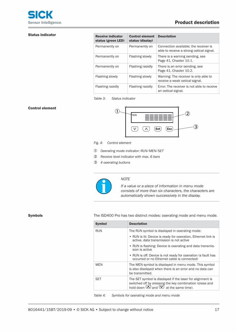
Status indicator Receive indicator status (green LED)
Control element status (display)
Description
Permanently on Permanently on Connection available; the receiver is able to receive a strong optical signal.
Permanently on Flashing slowly There is a warning pending, see Page 41, Chapter 10.1.
Permanently on Flashing rapidly There is an error pending, see Page 41, Chapter 10.2.
Flashing slowly Flashing slowly Warning: The receiver is only able to receive a weak optical signal.
Flashing rapidly Flashing rapidly Error: The receiver is not able to receive an optical signal.
Table 3: Status indicator
Control element
3
2
EscSet
RUN1
Fig. 4: Control element
1 Operating mode indicator: RUN/MEN/SET
2 Receive level indicator with max. 6 bars
3 4 operating buttons
NOTE
If a value or a piece of information in menu mode consists of more than six characters, the characters are automatically shown successively in the display.
Symbols The ISD400 Pro has two distinct modes: operating mode and menu mode.
Symbol Description
RUN The RUN symbol is displayed in operating mode:
• RUN is lit: Device is ready for operation, Ethernet link is active, data transmission is not active
• RUN is flashing: Device is operating and data transmis-sion is active
• RUN is off: Device is not ready for operation (a fault has occurred or no Ethernet cable is connected)
MEN The MEN symbol is displayed in menu mode. This symbol is also displayed when there is an error and no data can be transmitted.
SET The SET symbol is displayed if the laser for alignment is switched off by pressing the key combination (press and hold down and at the same time).
Table 4: Symbols for operating mode and menu mode
Product description
18 © SICK AG • Subject to change without notice • 8016441/15BT/2019-09
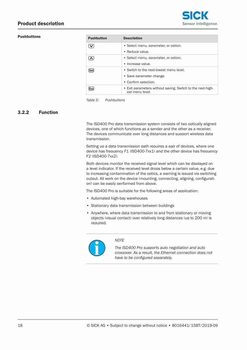
Pushbuttons Pushbutton Description
• Select menu, parameter, or option.
• Reduce value.
• Select menu, parameter, or option.
• Increase value.
• Switch to the next-lowest menu level.
• Save parameter change.
• Confirm selection.
• Exit parameters without saving. Switch to the next-high-est menu level.
Table 5: Pushbuttons
3.2.2 Function
The ISD400 Pro data transmission system consists of two optically aligned devices, one of which functions as a sender and the other as a receiver. The devices communicate over long distances and support wireless data transmission.
Setting up a data transmission path requires a pair of devices, where one device has frequency F1 (ISD400-7xx1) and the other device has frequency F2 (ISD400-7xx2).
Both devices monitor the received signal level which can be displayed on a level indicator. If the received level drops below a certain value, e.g. due to increasing contamination of the optics, a warning is issued via switching output. All work on the device (mounting, connecting, aligning, configurati-on) can be easily performed from above.
The ISD400 Pro is suitable for the following areas of application:
• Automated high-bay warehouses
• Stationary data transmission between buildings
• Anywhere, where data transmission to and from stationary or moving objects (visual contact) over relatively long distances (up to 200 m) is required.
NOTE
The ISD400 Pro supports auto negotiation and auto crossover. As a result, the Ethernet connection does not have to be configured separately.
8016441/15BT/2019-09 • © SICK AG • Subject to change without notice 19
Transport and storage
4 Transport and storage
4.1 Transport
Improper transportNOTICE
Improperly transporting the data transmission system may damage it.
Considerable material damage may occur in the event of improper transport.
For this reason:
• Transport should be performed by trained specialist staff only.
• The utmost care and attention is required at all times during unloading and transportation on company premises.
• Note the symbols on the packaging.
• Do not remove packaging until immediately before you start mounting.
4.2 Transport inspection
Improper transport Upon receipt, please check the delivery for completeness and for any da-mage that may have occurred in transit.
In the case of transit damage that is visible externally, proceed as follows:
• Do not accept the delivery or only do so conditionally.
• Note the scope of damage on the transport documents or on the transport company's delivery note.
• File a complaint.
NOTE
Complaints regarding defects should be filed as soon as these are detected. Damage claims are only valid before the applicable complaint deadlines.

Transport and storage
20 © SICK AG • Subject to change without notice • 8016441/15BT/2019-09
4.3 Storage
Please consider the following conditions when storing the ISD400 Pro:
• Do not store outdoors.
• Store in a dry area that is protected from dust.
• Do not expose to any aggressive substances.
• Protect from sunlight.
• Avoid mechanical shocks.
• Storage temperature: between –40 and +75 °C
• Relative humidity: max. 95 %, non-condensing
• For storage periods of longer than 3 months, check the general condi-tion of all components and packaging on a regular basis.

8016441/15BT/2019-09 • © SICK AG • Subject to change without notice 21
Mounting
5 Mounting
5.1 Mounting procedure
1. Choose a mounting site, bearing in mind the mounting instructions. → See the following chapter.
2. Mount the alignment bracket and data transmission system. → See Page 24, Chapter 5.4.
3. Make the electrical connection. → See Page 26, Chapter 6.
4. Align the devices of the data transmission system with one another. → See Page 31, Chapter 7.1.
5.2 Mounting instructions
To ensure trouble-free operation, the following mounting instructions should be observed:
• Comply with technical data such as the measuring range. → See Page 44, Chapter 11.2.
• At low ambient temperatures – e.g. in deep-freeze warehouses – the data transmission system should have integrated heating.
• Protect the data transmission system from direct sunlight.
• To prevent condensation water, avoid exposing the data transmission system to rapid changes in temperature.
• Make sure the system is a sufficient distance from other optical measu-ring devices and data transmission systems. → See Page 22, Chap-ter 5.3.

Mounting
22 © SICK AG • Subject to change without notice • 8016441/15BT/2019-09
5.3 Arranging multiple optical devices
In some applications, multiple optical devices must be operated side by side. In these cases, minimum mounting distances must be observed.
Mounting multiple ISD400 Pro
a
a > d x 0.0055 + 0.1 m
d
�
�
�
�
Fig. 5: Arranging multiple ISD400 Pro
1 ISD400-7xx1, red
2 ISD400-7xx2, infrared
a Minimum distance
NOTE
Mount devices 1 and 2 of the device pair at an angle of 180° relative to one another.
Formula a > d x 0.0055 + 0.1 m
Example • Measuring range: 0 … 200 m
• d (measuring distance): 100 m
Calculationa > 100 m x 0.0055 + 0.1 m
Minimum distance resulta > 0.65 m

8016441/15BT/2019-09 • © SICK AG • Subject to change without notice 23
Mounting
Mounting the ISD400 Pro and other optical devices
a
d
�
�
�
�
a > d x 0.0083
Fig. 6: Arranging the ISD400 Pro and a DL100 Pro distance-measuring device
1 DL100 Pro distance-measuring device
2 Reflector
3 ISD400-7xx1, red
4 ISD400-7xx2, infrared
a Minimum distance
NOTE
Mount devices 3 and 4 of the device pair at an angle of 180° relative to one another.
Formula a > d x 0.0083
Example • Measuring range: 0 … 200 m
• d (measuring distance): 100 m
Calculationa > 100 m x 0.0083
Minimum distance resulta > 0.83 m

Mounting
24 © SICK AG • Subject to change without notice • 8016441/15BT/2019-09
5.4 Mounting the ISD400 Pro
NOTE
→ For mounting accessories, go to "www.sick.com/isd400_pro", "Accessories".
Fig. 7: ISD400 Pro mounting variants on alignment bracket (2046052)
133
(5.2
4)
211.7 (8.33)
88 (3
.46)
211.7 (8.33)
All dimensions in mm (inch)Fig. 8: ISD400 Pro dimensions when mounted on alignment bracket (2046052)

8016441/15BT/2019-09 • © SICK AG • Subject to change without notice 25
Mounting
1. Select the mounting site for the ISD400 Pro in accordance with require-ments. Bear in mind the minimum mounting distances. → For dimen-sions, see Page 43, Chapter 11.1. The devices can be mounted horizontally or vertically on the bracket.
2. Install the devices at a 180° angle to one another, so the optical axes of the two devices match at minimum distance.
NOTE
→ Two transmission lines can be connected in series (cascaded).

Electrical connection
26 © SICK AG • Subject to change without notice • 8016441/15BT/2019-09
6 Electrical connection
6.1 Safety
Incorrect supply voltageNOTICE
Equipment damage due to incorrect supply voltage.
An incorrect supply voltage may result in damage to the equipment.
For this reason:
• The sensor must only be operated with a protected low voltage and a protected low voltage power supply.
Working with live partsNOTICE
Equipment damage or unpredictable operation due to working with live parts.
Working with live parts may result in unpredictable ope-ration.
For this reason:
• Only carry out wiring work when the power is off.
• Only connect and disconnect cable connections when the power is off.
6.2 Wiring notes
NOTICE
Faults due to incorrect wiring.
Incorrect wiring may result in operational faults.
For this reason:
• Follow the wiring notes precisely.
NOTE
We recommend using pre-assembled cables for the wi-ring. → For pre-assembled cables, go to "www.sick.com/isd400_pro", "Accessories".

8016441/15BT/2019-09 • © SICK AG • Subject to change without notice 27
Electrical connection
All electrical connections of the ISD400 Pro are configured as M12 round connectors.
The IP 65 protection class is only achieved using screwed plug connectors.
All electric circuits connected to the ISD400 Pro must be configured as PELV or SELV circuits (PELV= protective extra-low voltage, SELV = safety extra-low voltage).
By using appropriate cable entries and wiring, you can avoid interference from devices such as switching power supplies, motors, clocked drives, and contactors.
• Cables should be laid as far away as possible from cables with a high level of radiated emission. Take additional measures where necessary, e.g. separation by means of screening shields.
• Do not lay cables parallel to other cables, especially not to devices with a high level of radiated emission, such as a frequency converter.
• Do not lay cables parallel to energy cables.
Please observe the following wiring notes:
• A correct and complete cable shielding concept is required for trouble-free operation.
• The cable shield must be connected at both ends in the control cabinet and at the device. The cable shield of the pre-assembled cable is con-nected to the knurled nut and thus also to the device housing.
• The cable shield in the control cabinet must be connected to the opera-ting ground over a large surface area.
• Appropriate measures must be taken to prevent equipotential bonding currents flowing through the cable shield.
• Do not lay cables parallel to other cables, especially not to devices with a high level of radiated emission, such as a frequency converter.
12
4
3
1
2
4
3
90
90
Fig. 9: Cross cables at right angles

Electrical connection
28 © SICK AG • Subject to change without notice • 8016441/15BT/2019-09
1
2
3
4
Fig. 10: Ideal laying – Place cables in different cable channels
1
2 3
4
Fig. 11: Alternative laying – Separate cables with metallic separators
1 Cables very sensitive to interference (analog measuring cables)
2 Cables sensitive to interference (sensor cables, communication signals, bus signals)
3 Cables which are a source of interference (control cables for inductive loads, motor brakes)
4 Cables which are powerful sources of interference (output cables from fre-quency inverters, welding system power supplies, power cables)
Fig. 12: Attach the screen using a short connection with a large surface area – ground both ends
6.3 Connecting the ISD400 Pro electrically
1. Ensure that there is no voltage.
2. Connect the ISD400 Pro according to the connection diagram. → See Page 29, Chapter 6.4.
8016441/15BT/2019-09 • © SICK AG • Subject to change without notice 29
Electrical connection
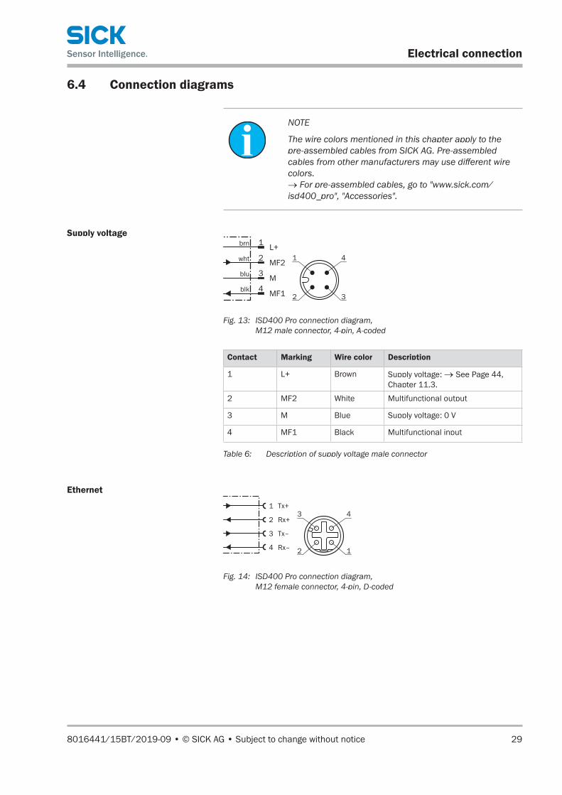
6.4 Connection diagrams
NOTE
The wire colors mentioned in this chapter apply to the pre-assembled cables from SICK AG. Pre-assembled cables from other manufacturers may use different wire colors. → For pre-assembled cables, go to "www.sick.com/isd400_pro", "Accessories".
Supply voltageL+
MF2
M
MF1
1
2
4
wht
blu
brn
blk
3
1
2
4
3
Fig. 13: ISD400 Pro connection diagram, M12 male connector, 4-pin, A-coded
Contact Marking Wire color Description
1 L+ Brown Supply voltage: → See Page 44, Chapter 11.3.
2 MF2 White Multifunctional output
3 M Blue Supply voltage: 0 V
4 MF1 Black Multifunctional input
Table 6: Description of supply voltage male connector
Ethernet
Tx+
Rx+
Tx–
Rx–
1
2
4
3
3
2
4
1
Fig. 14: ISD400 Pro connection diagram, M12 female connector, 4-pin, D-coded

Electrical connection
30 © SICK AG • Subject to change without notice • 8016441/15BT/2019-09
Contact Marking Description
1 Tx+ Send data signal, not inverted
2 Rx+ Receive data signal, not inverted
3 Tx– Send data signal, inverted
4 Rx– Receive data signal, inverted
Table 7: Description of Ethernet female connector

8016441/15BT/2019-09 • © SICK AG • Subject to change without notice 31
Commissioning
7 Commissioning
7.1 Aligning the ISD400 Pro
1. Bring the connected devices F1 and F2 as close as possible to one another.
b Device is in operating mode. An established optical connection with the device opposite is indicated by the receive indicator.
2. At close range (<1 m), align the device with a straight, mechanical tool such as a long spirit level if necessary, until the green receive indicator lights up.
3. Move devices F1 and F2 away from one another until the connection is lost and the green receive indicator 3 is flashing on one of them.
4. Realign the devices. To use the optical alignment aid on device F1 (ISD400-7xx1), switch off the laser: Press and at the same time.
5. Readjust with the alignment sight and optical alignment aid with cross-hairs until the green receive indicator lights up on device F1. If there is a low reception level, the opposing sender must be realigned. In operating mode, the quality of the alignment of the sender can be read directly from the display of the receiver.
6. Switch the laser on again on device F1 (ISD400-7xx1): Press .
7. Check the alignment using the level indicator and fine-tune if necessa-ry to adjust.
Operating the device
32 © SICK AG • Subject to change without notice • 8016441/15BT/2019-09
8 Operating the device
NOTICE
Pushbutton damage due to improper handling.
Improper handling of the pushbuttons can damage them. This will make operation difficult or impossible.
For this reason:
• Only operate the pushbuttons with your fingers or a suitable pointing device.
• Do not operate the pushbuttons using sharp or hard objects.
8.1 Displaying the received signal level
As soon as voltage is supplied to the device, the signal level is indicated on the display.
8.2 Selecting parameters
You can select a menu, parameter, or option using the , , and pushbuttons. The menu path is specified in the relevant chapters. → For the overall menu structure, see Page 47, Chapter 13.
8.3 Selecting options
1. Select the desired parameter using the and pushbuttons.
2. Select the desired option using the or pushbutton.
3. Perform one of the following steps:
• Press the pushbutton to save the change.
• Press the pushbutton to cancel the process. The parameter name is displayed again.
4. Perform one of the following steps to return to the level indicator:
• Press the pushbutton repeatedly until the received signal level is displayed once more.
• Wait for approx. 2 minutes. The display will automatically switch back to the receive level indicator if no buttons are pressed. Any settings you have made will also be saved.
8016441/15BT/2019-09 • © SICK AG • Subject to change without notice 33
Operating the device
8.4 Changing the value
1. Select the desired parameter using the , , and pushbuttons.
2. Press the pushbutton. The current value of the parameter is dis-played. The first digit on the left flashes.
3. Press the pushbutton to increase the digit. Press the pushbut-ton to lower the digit.
4. Press the pushbutton to save the digit entered. The next digit flashes. Press the pushbutton to cancel the process.
5. Repeat steps 3 and 4 until the last digit is saved. The parameter name is displayed.
6. Press the pushbutton repeatedly until the received signal level is displayed once more. Alternatively, you can wait a few minutes. The display will automatically switch back to the receive level indicator if no buttons are pressed.
Operating the device
34 © SICK AG • Subject to change without notice • 8016441/15BT/2019-09
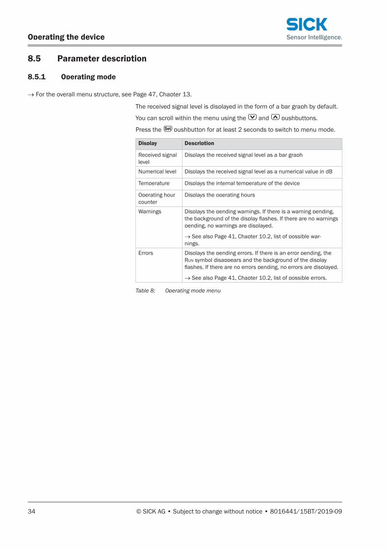
8.5 Parameter description
8.5.1 Operating mode
→ For the overall menu structure, see Page 47, Chapter 13.
The received signal level is displayed in the form of a bar graph by default.
You can scroll within the menu using the and pushbuttons.
Press the pushbutton for at least 2 seconds to switch to menu mode.
Display Description
Received signal level
Displays the received signal level as a bar graph
Numerical level Displays the received signal level as a numerical value in dB
Temperature Displays the internal temperature of the device
Operating hour counter
Displays the operating hours
Warnings Displays the pending warnings. If there is a warning pending, the background of the display flashes. If there are no warnings pending, no warnings are displayed.
→ See also Page 41, Chapter 10.2, list of possible war-nings.
Errors Displays the pending errors. If there is an error pending, the Run symbol disappears and the background of the display flashes. If there are no errors pending, no errors are displayed.
→ See also Page 41, Chapter 10.2, list of possible errors.
Table 8: Operating mode menu
8016441/15BT/2019-09 • © SICK AG • Subject to change without notice 35
Operating the device
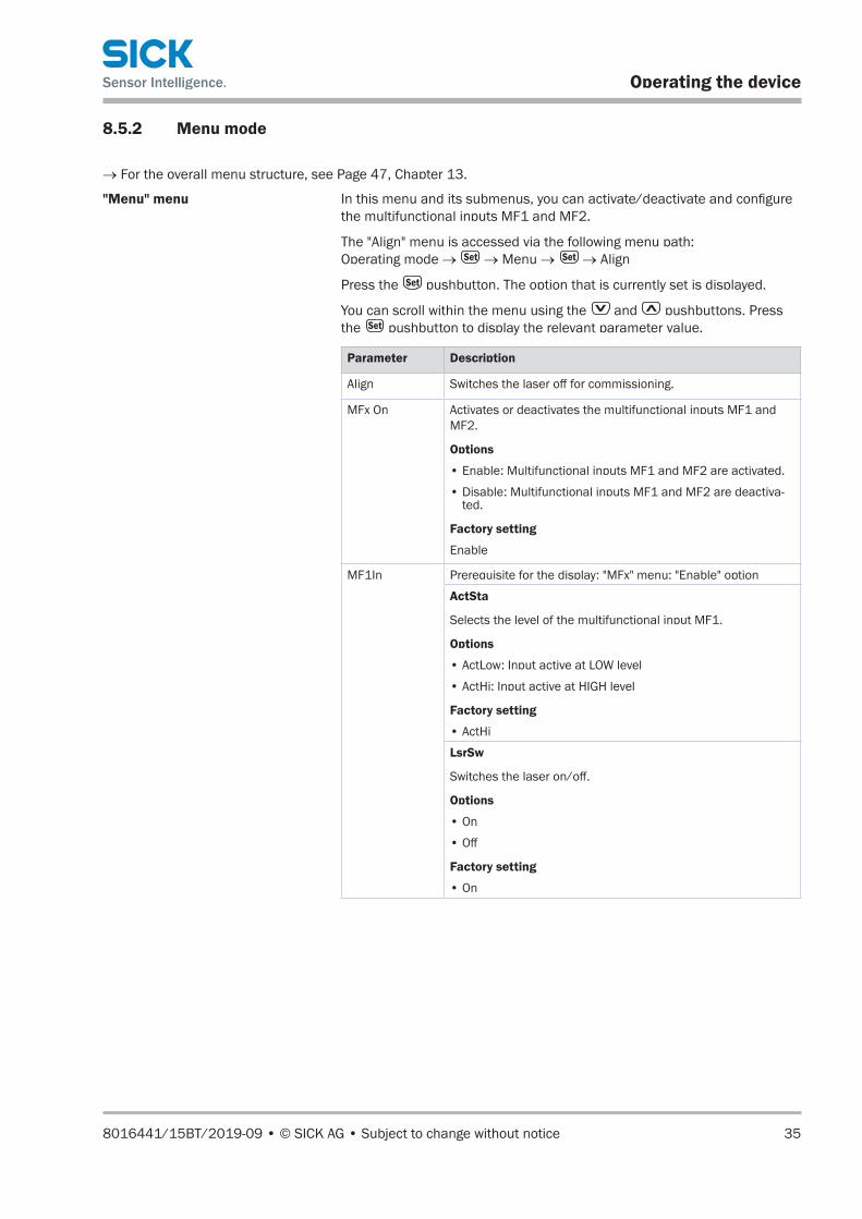
8.5.2 Menu mode
→ For the overall menu structure, see Page 47, Chapter 13.
"Menu" menu In this menu and its submenus, you can activate/deactivate and configure the multifunctional inputs MF1 and MF2.
The "Align" menu is accessed via the following menu path: Operating mode → → Menu → → Align
Press the pushbutton. The option that is currently set is displayed.
You can scroll within the menu using the and pushbuttons. Press the pushbutton to display the relevant parameter value.
Parameter Description
Align Switches the laser off for commissioning.
MFx On Activates or deactivates the multifunctional inputs MF1 and MF2.
Options
• Enable: Multifunctional inputs MF1 and MF2 are activated.
• Disable: Multifunctional inputs MF1 and MF2 are deactiva-ted.
Factory setting
Enable
MF1In Prerequisite for the display: "MFx" menu: "Enable" option
ActSta
Selects the level of the multifunctional input MF1.
Options
• ActLow: Input active at LOW level
• ActHi: Input active at HIGH level
Factory setting
• ActHi
LsrSw
Switches the laser on/off.
Options
• On
• Off
Factory setting
• On
Operating the device
36 © SICK AG • Subject to change without notice • 8016441/15BT/2019-09
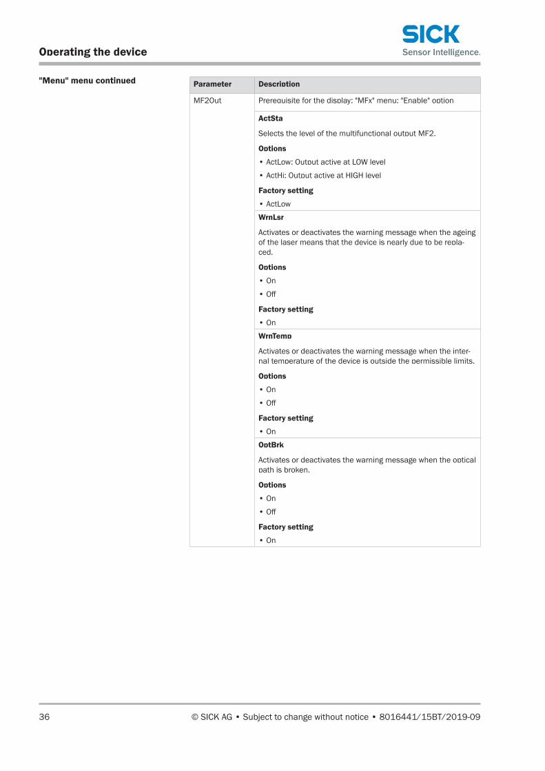
"Menu" menu continued Parameter Description
MF2Out Prerequisite for the display: "MFx" menu: "Enable" option
ActSta
Selects the level of the multifunctional output MF2.
Options
• ActLow: Output active at LOW level
• ActHi: Output active at HIGH level
Factory setting
• ActLow
WrnLsr
Activates or deactivates the warning message when the ageing of the laser means that the device is nearly due to be repla-ced.
Options
• On
• Off
Factory setting
• On
WrnTemp
Activates or deactivates the warning message when the inter-nal temperature of the device is outside the permissible limits.
Options
• On
• Off
Factory setting
• On
OptBrk
Activates or deactivates the warning message when the optical path is broken.
Options
• On
• Off
Factory setting
• On

8016441/15BT/2019-09 • © SICK AG • Subject to change without notice 37
Operating the device
"Menu" menu continued Parameter Description
MF2Out EthLnk
Activates or deactivates the warning message when there is no Ethernet cable connected.
Options
• On
• Off
Factory setting
• Off
WrnLvl
Activates or deactivates the warning message when the recei-ved signal level drops, e.g. due to contamination.
Options
• On
• Off
Factory setting
• Off
NotRdy:Activates or deactivates the warning message when the laser is not ready for operation. This may be due to a hardware error or it may be because the laser is switched off. This warning message is also issued during initialization.Options
• On
• Off
Factory setting
• On
Heat
Activates or deactivates the warning message when the heating is switched on. This parameter is only displayed on devices with the "Heating" option (ISD400-7X2X)
Options
• On
• Off
Factory setting
• Off
Heat • This parameter is only displayed on devices with the "Hea-ting" option (ISD400-7X2X)
• Defines the switch-on threshold for the heating (–10 to +40 °C).
Factory setting
• –10 °C
Reset Resets all parameters in the menu.
Table 9: "Menu" menu

Operating the device
38 © SICK AG • Subject to change without notice • 8016441/15BT/2019-09
"Count" menu The "Count" menu displays all counts for the switching events in Table 10 (page 38). You can reset the counter by switching the device off and on again.
The "Count" menu is accessed via the following menu path: Operating mode → → Menu → → Count
Press the pushbutton to display the "OptBrk" parameter.
Parameter Description
OptBrk Number of light path interruptions
WrnTmp Number of temperature warnings
EthLink Number of Ethernet link interruptions
Reset Yes: Resets all counters in the "Count" menu.
Table 10: "Count" menu
NOTE
If a value or a piece of information in menu mode consists of more than six characters, the characters are automatically shown successively in the display.
"SwVers" menu The "SwVers" menu displays all information relating to the software.
The "SwVers" menu is accessed via the following menu path: Operating mode → → Menu → → SwVers
Press the pushbutton to display the "SwVers" parameter.
Parameter Description
SwVers Displays the version number
Table 11: "SwVers" menu
NOTE
If a value or a piece of information in menu mode consists of more than six characters, the characters are automatically shown successively in the display.
"HwVers" menu The "HwVers" menu displays all information relating to the hardware.
The "HwVers" menu is accessed via the following menu path: Operating mode → → Menu → → HwVers
Press the pushbutton to display the "HwVers" parameter.
Parameter Description
HwVers Displays the version number
Table 12: "HwVers" menu

8016441/15BT/2019-09 • © SICK AG • Subject to change without notice 39
Operating the device
8.6 Performing a reset
1. Select the "Reset" parameter in the "Menu" menu. → See Page 35, Chapter 8.5.2.
2. Press the pushbutton.
3. The confirmation prompt "Sure?" appears.
4. Press the pushbutton to reset the device to its initial state. Press the pushbutton to cancel the process.
Cleaning and maintenance
40 © SICK AG • Subject to change without notice • 8016441/15BT/2019-09
9 Cleaning and maintenance
9.1 Cleaning
NOTICE
Equipment damage due to improper cleaning.
Improper cleaning may result in equipment damage.
For this reason:
• Never use cleaning agents containing aggressive substances.
• Never use pointed objects for cleaning.
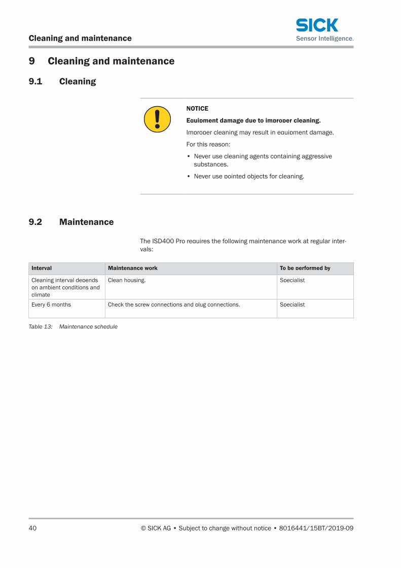
9.2 Maintenance
The ISD400 Pro requires the following maintenance work at regular inter-vals:
Interval Maintenance work To be performed by
Cleaning interval depends on ambient conditions and climate
Clean housing. Specialist
Every 6 months Check the screw connections and plug connections. Specialist
Table 13: Maintenance schedule
Troubleshooting
41 © SICK AG • Subject to change without notice • 8016441/15BT/2019-09
10 Troubleshooting
Possible faults and rectification measures are described in the table below.
In case of faults that cannot be rectified using the information below, please contact the manufacturer. A list of representatives can be found on the back page.
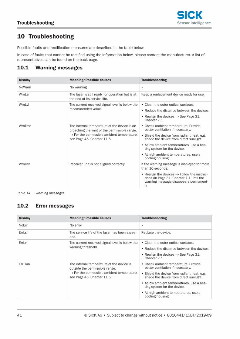
10.1 Warning messages
Display Meaning/Possible causes Troubleshooting
NoWarn No warning –
WrnLsr The laser is still ready for operation but is at the end of its service life.
Keep a replacement device ready for use.
WrnLvl The current received signal level is below the recommended value.
• Clean the outer optical surfaces.
• Reduce the distance between the devices.
• Realign the devices → See Page 31, Chapter 7.1
WrnTmp The internal temperature of the device is ap-proaching the limit of the permissible range. → For the permissible ambient temperature, see Page 45, Chapter 11.5.
• Check ambient temperature. Provide better ventilation if necessary.
• Shield the device from radiant heat, e.g. shade the device from direct sunlight.
• At low ambient temperatures, use a hea-ting system for the device.
• At high ambient temperatures, use a cooling housing.
WrnOvr Receiver unit is not aligned correctly. If the warning message is displayed for more than 10 seconds:
• Realign the devices → Follow the instruc-tions on Page 31, Chapter 7.1 until the warning message disappears permanent-ly.
Table 14: Warning messages
10.2 Error messages
Display Meaning/Possible causes Troubleshooting
NoErr No error –
ErrLsr The service life of the laser has been excee-ded.
Replace the device.
ErrLvl The current received signal level is below the warning threshold.
• Clean the outer optical surfaces.
• Reduce the distance between the devices.
• Realign the devices → See Page 31, Chapter 7.1
ErrTmp The internal temperature of the device is outside the permissible range. → For the permissible ambient temperature, see Page 45, Chapter 11.5.
• Check ambient temperature. Provide better ventilation if necessary.
• Shield the device from radiant heat, e.g. shade the device from direct sunlight.
• At low ambient temperatures, use a hea-ting system for the device.
• At high ambient temperatures, use a cooling housing.

Troubleshooting
42 © SICK AG • Subject to change without notice • 8016441/15BT/2019-09
Display Meaning/Possible causes Troubleshooting
ErrHv Receiver unit is faulty. Device is not ready for operation, contact customer service (a list of representatives can be found on the back page).
LsrOff Laser has been switched off for commissi-oning.
Device F1 (ISD400-7xx1): Switch on laser: Press .
Table 15: Error messages
10.3 Possible error indicators
Problem Possible causes Troubleshooting
Green receive indicator and display are flashing rapidly, no signal
Two devices with the same frequency (F1/F1; F2/F2), no frequency pair mounted.
Mount devices with different frequencies (F1/F2).
Laser switched off, device not in operating mode
Device F1 (ISD400-7xx1): Switch on laser: Press .
Minimum mounting distances not observed. • When using multiple sensors, observe the minimum mounting distances → See Page 22, Chapter 5.3.
Receive indicator off No power supply/hardware faulty • Check connection.
• Replace device.
No RUN symbol in the display No Ethernet cable connected.
No optical connection to communication partner available.
• Check cabling.
• Check Ethernet settings on opposite side.
• Check alignment.
Table 16: Possible error indicators
10.4 Disposal
Please observe the following when disposing of the device:
• Do not dispose of the device along with household waste.
• Dispose of the device according to the applicable regulations in your country.

8016441/15BT/2019-09 • © SICK AG • Subject to change without notice 43
Technical data
11 Technical data
NOTE
You can download, save, and print the relevant online data sheet for your ISD400 Pro, including technical data, dimensions, and connection diagrams, from "www.sick.com/isd400_pro".
11.1 Dimensions
2
1
M6
3
4
9
6
8
5
7
Esc
Set
1
71.7(2.82)
40 (1.5
7)
30(1.18)
60 (2.34) 123.5 (4.86)
32 (1.2
6)
116.2 (4.57)
68.7 (2.70)
105
(4.1
3)
83 (3
.27)
11
(0.4
3)
All dimensions in mm (inch)
Fig. 15: ISD400 Pro structure
1 Threaded mounting hole M6
2 Center of optical axis, sender
3 Receive indicator
4 Center of optical axis, receiver
5 Ethernet female connector, M12, 4-pin, D-coded
6 Power supply male connector, M12, 4-pin, A-coded
7 Control element
8 Optical alignment aid
9 Alignment sight

Technical data
44 © SICK AG • Subject to change without notice • 8016441/15BT/2019-09
11.2 Performance data
Light sender • Red laser (ISD400-7xx1): 660 nm
• Infrared laser (ISD400-7xx2): 785 nmLight spot size (distance) 1.75 m (at 100m); diameter = 0.0175 m x d(m)
Transmission range • 0,2 ... 150 m (ISD400-72xx)
• 0,2 ... 200 m (ISD400-73xx)Aperture angle • Sender: 1°
• Receiver: 1.5°Ambient light • <10 klux (ISD400-72xx)
• <5 klux (ISD400-73xx)Table 17: Performance data
11.3 Power supply
Supply voltage UV 1) DC 18–30 V
Circuit protection UV connections, reverse polarity protected
Power consumption (without load) • ≤3.6 W (without heating)
• ≤50 W (with heating)
1) Limit values, reverse polarity protected
Table 18: Power supply
11.4 Interfaces
Data interface Fast Ethernet
Data transmission rate 100 Mbit/s
Signal delay ≤ 1,5 µs
Multifunctional output 1) Hi: Uv – 3 V, Lo: <2 V
Maximum output current IA 100 mA
Multifunctional input Hi: >8V, Lo: <5V
1) Short-circuit and overload protected
Table 19: Interfaces
8016441/15BT/2019-09 • © SICK AG • Subject to change without notice 45
Technical data
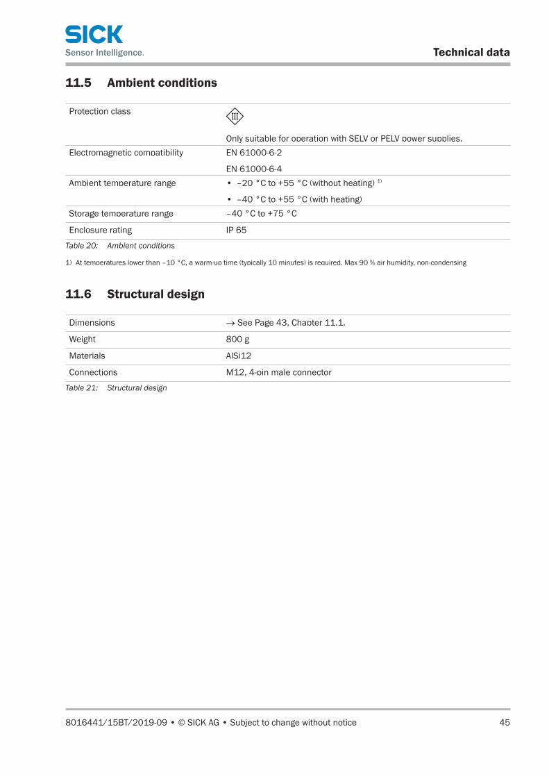
11.5 Ambient conditions
Protection class
Only suitable for operation with SELV or PELV power supplies.Electromagnetic compatibility EN 61000-6-2
EN 61000-6-4Ambient temperature range • –20 °C to +55 °C (without heating) 1)
• –40 °C to +55 °C (with heating)Storage temperature range –40 °C to +75 °C
Enclosure rating IP 65
Table 20: Ambient conditions
1) At temperatures lower than –10 °C, a warm-up time (typically 10 minutes) is required. Max 90 % air humidity, non-condensing
11.6 Structural design
Dimensions → See Page 43, Chapter 11.1.
Weight 800 g
Materials AlSi12
Connections M12, 4-pin male connector
Table 21: Structural design

Accessories
46 © SICK AG • Subject to change without notice • 8016441/15BT/2019-09
12 Accessories
NOTE
For additional accessories, go to "www.sick.com/isd400_pro", "Accessories".
12.1 Supply cable
Description Straight M12 female cable connector with cable, 4-pin, without shielding, 10 m
Part no. 6025902
12.2 Ethernet cable
Description Ethernet cable, M12 male connector, 4-pin, straight/RJ45, shielding, CAT5, 10 m
Part no. 6047918
12.3 Alignment bracket
Description Alignment bracket for DME4000, DME5000, and ISD400 ProPart no. 2046052

8016441/15BT/2019-09 • © SICK AG • Subject to change without notice 47
Menu structure
13 Menu structure
NOTE
The default settings are shown with a gray background.
NOTE
If a value or a piece of information in menu mode consists of more than six characters, the characters are automatically shown successively in the display.
RUN –010 °C
RUN –074 dB
RUN
RUN 00200h
RUN NoWarnRUN WrnLsrRUN WrnLvlRUN WrnTmp
RUN NoErrRUN ErrLsrRUN ErrLvlRUN ErrTmpRUN ErrHvRUN LsrOff
RUN WrnOvr
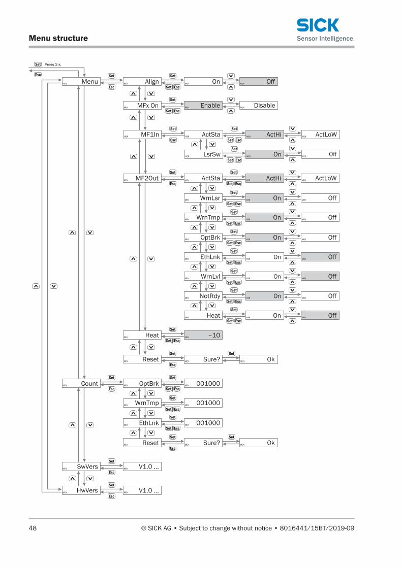
Menu structure
48 © SICK AG • Subject to change without notice • 8016441/15BT/2019-09
ANCHOR
MEN Menu MEN Align
MEN MF2Out
MEN SwVers
MEN HwVers
MEN Reset
MEN V1.0 …
MEN On MEN Off
MEN ActLoWMEN ActSta MEN ActHi
MEN V1.0 …
MEN EnableMEN MFx On DisableMEN
MEN WrnLsr MEN On MEN Off
MEN WrnTmp MEN On MEN Off
MEN OptBrk MEN On MEN Off
MEN EthLnk MEN On MEN Off
MEN WrnLvl MEN On MEN Off
MEN NotRdy MEN On MEN Off
MEN Heat MEN On MEN Off
MEN MF1In MEN ActSta
MEN LsrSw
MEN ActLoWMEN ActHi
MEN On MEN Off
MEN –10MEN Heat
MEN Count MEN OptBrk
MEN WrnTmp
MEN EthLnk
MEN Reset
MEN 001000
MEN 001000
MEN 001000
Press 2 s.
MEN Sure? MEN Ok
MEN Sure? MEN Ok

8016441/15BT/2019-09 • © SICK AG • Subject to change without notice 49
Index
AAccessories.................................................................... 46Ambient conditions ....................................................... 45
CCleaning ......................................................................... 40Configuration overview ................................................. 47Correct use .................................................................... 10Customer service .............................................................8
DDimensions .................................................................... 43Disposal ......................................................................... 42
EEC declaration of conformity ...........................................9Electrical connection..................................................... 26Electricians .................................................................... 11
FFactory setting ............................................................... 39Function ......................................................................... 18
GGeneral information .........................................................7
HHazard warnings ............................................................ 13
IIdentification .................................................................. 15Incorrect use .................................................................. 10Inputs ............................................................................. 44
LLaser radiation .................................................12, 13, 14Limitation of liability .........................................................8
MMaintenance ................................................................. 40Minimum distance ........................................................ 22Mounting
For smooth object surfaces .................................... 22General information ................................................ 21Minimum distance.............................................22, 23Multiple sensors ...................................................... 22Notes ........................................................................ 21Procedure ................................................................. 21
OOperating instructions .....................................................7Operating modes ........................................................... 17Operating personnel
Requirements .......................................................... 11Operation
Changing the value .................................................. 33On the measuring device ........................................ 32Selecting options ..................................................... 32Selecting parameters .............................................. 32
Operational safety ...................................................11, 13Overview of settings ...................................................... 47
PParameter description .................................................. 34
Main menu .........................................................34, 35MFx On ..................................................................... 35SwVers ...................................................................... 38
Performance data ......................................................... 44Power supply ................................................................. 44Pushbuttons .................................................................. 18
RReset .............................................................................. 39
SSafety ............................................................................. 10
Electrical connection ............................................... 26Scope of delivery ..............................................................8Skilled personnel .......................................................... 11
Requirements .......................................................... 11Smooth object surfaces ................................................ 22Status displays .............................................................. 17Status indicators ........................................................... 16Storage ........................................................................... 20Structural design ........................................................... 45Structure ........................................................................ 16
TTechnical data ............................................................... 43Transport ........................................................................ 19Transport inspection ..................................................... 19Troubleshooting ............................................................. 41Type code ....................................................................... 15Type label ....................................................................... 15
WWiring notes ................................................................... 26
Index
SICK AG | Waldkirch | Germany | www.sick.com
8016
441/
15BT
/201
9-09
AustraliaPhone +61 (3) 9457 0600 1800 33 48 02 – tollfreeE-Mail [email protected]
AustriaPhone +43 (0) 2236 62288-0E-Mail [email protected]
Belgium/LuxembourgPhone +32 (0) 2 466 55 66E-Mail [email protected]
BrazilPhone +55 11 3215-4900E-Mail [email protected]
CanadaPhone +1 905.771.1444E-Mail [email protected]
Czech RepublicPhone +420 2 57 91 18 50E-Mail [email protected]
ChilePhone +56 (2) 2274 7430E-Mail [email protected]
ChinaPhone +86 20 2882 3600E-Mail [email protected]
DenmarkPhone +45 45 82 64 00E-Mail [email protected]
FinlandPhone +358-9-25 15 800E-Mail [email protected]
FrancePhone +33 1 64 62 35 00E-Mail [email protected]
GermanyPhone +49 (0) 2 11 53 01E-Mail [email protected]
Hong KongPhone +852 2153 6300E-Mail [email protected]
HungaryPhone +36 1 371 2680E-Mail [email protected]
IndiaPhone +91-22-6119 8900E-Mail [email protected]
IsraelPhone +972-4-6881000E-Mail [email protected]
ItalyPhone +39 02 27 43 41E-Mail [email protected]
JapanPhone +81 3 5309 2112E-Mail [email protected]
MalaysiaPhone +603-8080 7425E-Mail [email protected]
MexicoPhone +52 (472) 748 9451E-Mail [email protected]
NetherlandsPhone +31 (0) 30 229 25 44E-Mail [email protected]
New Zealand Phone +64 9 415 0459 0800 222 278 – tollfreeE-Mail [email protected]
Norway Phone +47 67 81 50 00E-Mail [email protected]
PolandPhone +48 22 539 41 00E-Mail [email protected]
RomaniaPhone +40 356-17 11 20 E-Mail [email protected]
RussiaPhone +7 495 283 09 90E-Mail [email protected]
SingaporePhone +65 6744 3732E-Mail [email protected]
SlovakiaPhone +421 482 901 201E-Mail [email protected]
SloveniaPhone +386 591 78849E-Mail [email protected]
South AfricaPhone +27 (0)11 472 3733E-Mail [email protected]
South KoreaPhone +82 2 786 6321E-Mail [email protected]
SpainPhone +34 93 480 31 00E-Mail [email protected]
SwedenPhone +46 10 110 10 00E-Mail [email protected]
SwitzerlandPhone +41 41 619 29 39E-Mail [email protected]
TaiwanPhone +886-2-2375-6288E-Mail [email protected]
ThailandPhone +66 2 645 0009E-Mail [email protected]
TurkeyPhone +90 (216) 528 50 00E-Mail [email protected]
United Arab EmiratesPhone +971 (0) 4 88 65 878E-Mail [email protected]
United KingdomPhone +44 (0)17278 31121E-Mail [email protected]
USAPhone +1 800.325.7425 E-Mail [email protected]
VietnamPhone +65 6744 3732E-Mail [email protected]