
Operating Instructions for deep fat fryers In Marine … Instructions for deep fat fryers ... 4.5...
31
Operating Instructions for deep fat fryers In Marine SOLAS version Applicable to models: SERIES 2000 V200 V2200 V200T V2200T V250 V400 V250T V400T V600 Your model: Please give the information below when ordering or requesting repairs. Spares: see page 11 Your service centre: Declaration of conformity Valentine Fabrique SA 6, Avenue d’Epenex CH - 1024 ECUBLENS Tél.: +41 21 634 32 23 Fax: +41 21 635 90 66 Internet: www.valentine.ch Mail: [email protected] confirms that the above-mentioned products conform to the following standards: Machine safety: EN 60335-2-37:95+A1:96: Par. 11, 13 and 19 EMC: EN 55014:93 and EN 55014-2:97 EN 61000-3-2:95 and EN 61000-3-3:95 Ecublens, 15 January 1998 The responsible officer from Valentine Fabrique SA The EEC representative: Name: M. F. Wenger Name: M. A. Holliday Board of Directors Director of Valentine Equipment LTD Reading RG1 8JS (GB) Date of creation: 15.01.98 by W/mm Date of modification: 10.09.01 by W/fd File: Fabrique SA Doc. N° A2000B SO Page No.: 1
-
Upload
phungquynh -
Category
Documents
-
view
220 -
download
1
Transcript of Operating Instructions for deep fat fryers In Marine … Instructions for deep fat fryers ... 4.5...
Operating Instructions for deep fat fryers In Marine SOLAS version Applicable to models: SERIES 2000 V200 V2200 V200T V2200T V250 V400 V250T V400T V600
Your model: Please give the information below when ordering or requesting repairs. Spares: see page 11
Your service centre:
Declaration of conformity Valentine Fabrique SA 6, Avenue d’Epenex CH - 1024 ECUBLENS Tél.: +41 21 634 32 23 Fax: +41 21 635 90 66 Internet: www.valentine.ch Mail: [email protected]
confirms that the above-mentioned products conform to the following standards: Machine safety: EN 60335-2-37:95+A1:96: Par. 11, 13 and 19 EMC: EN 55014:93 and EN 55014-2:97 EN 61000-3-2:95 and EN 61000-3-3:95 Ecublens, 15 January 1998 The responsible officer from Valentine Fabrique SA The EEC representative: Name: M. F. Wenger Name: M. A. Holliday Board of Directors Director of Valentine Equipment LTD Reading RG1 8JS (GB)
Date of creation: 15.01.98 by W/mm Date of modification: 10.09.01 by W/fd File:
Fabrique SA Doc. N° A2000B SO Page No.: 1

Date of creation: 15.01.98 by W/mm Date of modification: 03.09.03 by fd File:
Fabrique SA
Doc. N° A2000E Page No.: 2
Contents
Page No.:
1. Important information ___________________________________________________ 3
1.1 Warning_____________________________________________________________________ 3
1.2 Risks from food remnants______________________________________________________ 3
1.3 Periodic inspections __________________________________________________________ 3
2.Technical data _________________________________________________________ 4
3. Installation ____________________________________________________________ 4
3.1 Electrical connection __________________________________________________________ 4
3.2 Installation examples 3.2.1 Installation example I (Fig. 1)__________________________________________________________ 4 3.2.2 Installation example II (Fig. 2) _________________________________________________________ 4 3.2.3 Installation example III (Fig. 3)_________________________________________________________ 4
3.3 Cleaning ____________________________________________________________________ 5
4. Instructions for use_____________________________________________________ 7
4.1 Pouring in oil ________________________________________________________________ 7
4.2 Operation - Melting - Frying ____________________________________________________ 7
4.3 How to save oil _______________________________________________________________ 7
4.4 Oil care _____________________________________________________________________ 8
4.5 Maintenance of fryer, changing oil_______________________________________________ 8
5. Repairs _______________________________________________________________ 9
5.1 Simple faults_________________________________________________________________ 9
5.2 Complex faults _______________________________________________________________ 9
5.3 Security thermostat __________________________________________________________ 10
5.4 Safety switch _______________________________________________________________ 10
5.5 Spare parts _________________________________________________________________ 11
5.6 Circuit diagram _____________________________________________________________ 12
Warning: The information given in these operating instructions may be amended at any time. Valentine Fabrique SA accepts no liability for errors in these instructions and any consequent damage.

Date of creation: 15.01.98 by W/mm Date of modification: 03.09.03 by fd File:
Fabrique SA
Doc. N° A2000E Page No.: 3
Dear Customer, Congratulations on purchasing a Valentine fryer, a product of the best quality well known in Europe for 50 years.
The following operating instructions are based on EC and international regulations, as well as on the new product liability.
1. Important information
1.1 Warning
Before using the fryer you must:
⇒ study the following operating instructions and follow them closely
⇒ instruct the operating personnel and make them aware of the risk presented by food remains.
Valentine Fabrique SA accepts no liability for damage caused through improper operation and failure to adhere to these operating instructions.
1.2 Risks from food remnants
• Hot oil can cause severe burning. Therefore avoid any direct contact with the hot oil.
• Thoroughly drain the food to be fried before frying.
• Never allow water or ice to come into contact with the hot oil, otherwise the oil will spatter.
• Ensure that your face is not near the oil pan when food is immersed in it.
• Beware of clouds of steam and hot oil spray.
• Never allow anything but food to drop into the oil pan, e.g. gas cartridges, sealed bushings, etc. These explode and cause considerable spattering of oil.
• The fryer must not be operated without supervision. If a large amount of smoke develops, switch off immediately (switch to “ 0 ”)
• The oil level must not drop below the "MIN" oil level mark. If the oil level is too low there is a fire risk.
• N.B.: Old or frequently used oil/fat has a lower flash point and is more easily ignited. It may suddenly boil over when food is immersed.
• If the fryer catches fire, never extinguish with water. It is recommended that a fire extinguisher or fire extinguishing blanket be installed near the fryer.
Valentine fryers conform to the most stringent safety standards and are equipped with breakage-proof temperature limiters. Damage or fault must be excluded wherever humanly possible.
1.3 Periodic inspections
♦ Have the operation of the working thermostat and security thermostat checked (see 5.3)

Date of creation: 15.01.98 by W/mm Date of modification: 03.09.03 by fd File:
Fabrique SA
Doc. N° A2000E Page No.: 4
2. Technical data
Model:
Po
we
r [kW
]
Co
nn
ectio
n 3
P+
N+
E
3x4
00
V [A
]
Fre
qu
en
cy [H
z]
Co
nn
ectio
n c
ab
le
Ca
pa
city
in litre
s
Wo
rkin
g th
erm
osta
t
Sa
fety
the
rmo
sta
t
Tim
er
Ch
ips
fried
[kg
/h]
Pro
tectiv
e s
yste
m
We
igh
t [kg
]
Dim
en
sio
ns [c
m]
V200 7.2 10 50-60 5x1.5 7-9 1 1 1 19-23 IP X4 34 20x58x85
V200T 11 16 50-60 5x1.5 7-9 1 1 1 26-32 IP X4 34 20x58x85
V2200 14.4 20 50-60 5x2.5 2x 7-9 2 2 2 38-46 IP X4 52 40x58x85
V2200T 22 32 50-60 5x4 2x 7-9 2 2 2 52-64 IP X4 53 40x58x85
V250 7.2 10 50-60 5x1.5 8-10 1 1 1 19-23 IP X4 35 25x58x85
V250T 11 16 50-60 5x1.5 8-10 1 1 1 26-32 IP X4 35 25x58x85
V2525 14.4 20 50-60 5x2.5 2x 8-10 2 2 2 38-46 IP X4 55 50x58x85
V2525T 22 32 50-60 5x4 2x 8-10 2 2 2 52-64 IP X4 56 50x58x85
V400 14.4 20 50-60 5x2.5 18-20 1 2 1 38-46 IP X4 49 40X58X85
V400T 22 32 50-60 5x4 18-20 1 2 1 52-64 IP X4 50 40X58X85
V600 21.6 32 50-60 5x4 25-28 1 3 1 57-68 IP X4 69 60X58X85
3. Installation Erect fryer, to level rotate the setscrews underneath the front feet. The fryer must not stand on combustible surfaces. Local safety regulations must be complied with. N.B.: The slimline fryers V200 and V200T, as well as V250 and V250T, must not be freely erected (risk of tipping over). They must be installed between 2 units of furniture, or they must be supported on the sides.
3.1 Electrical connection Only experts may connect and commission the fryers. Your mains data (voltage, current, fuse protection) must conform to the data on the fryer rating plate (The rating plate is mounted on the inside of the door (Figs. 1 to 3 = D). The electrical connection must conform to local regulations, essentially as follows : - Fitting a mains plug on the connecting cable. Earth conductor = yellow/green, neutral conductor = blue Phase sequence is immaterial. - Any fixed connection must be made via a mains switch with all-pole isolation (min. contact distance 3 mm.). - Before connection is made to the mains, check that the main switch "E" of the fryer is in the "0" position. Never heat without oil !
3.2 Installation examples A considerable amount of steam is generated when preparing chips. A good steam extractor is strongly recommended.
3.2.1 Installation example I (Fig. 1) Wall socket [F] resistant to dripping water IP X2 or water spray IP X4
3.2.2 Installation example II (Fig. 2) Fryer free-standing or next to cooking range. Connection column [H] with socket IP X2 or IP X4
3.2.3 Installation example III (Fig. 3) Connection box [J] with 3P+N isolating switch arranged above fryer. Cable permanently connected. Because of the considerable steam generated the box must be watertight IP X5.
3.3 Cleaning
Pull the fryer forward [K] to clean the rear wall and bottom (Fig. 4). The cable must therefore be long enough to do this.

Date of creation: 15.01.98 by W/mm Date of modification: 03.09.03 by fd File:
Fabrique SA
Doc. N° A2000E Page No.: 5
Fig. 1: Fryer against wall Fig. 2: Fryer free-standing Fig. 3: Fryer against wall, with socket IP X2 (next to cooking range) with swichbox IP X5
N.B.: The V200 and V250 fryers, which are only 200 and 250 mm wide respectively, must be secured on the sides (risk of tipping over).
A Steam extractor F Wall socket IP X2 B Wall G Connecting cable 1,9 m C Heating element folded up H Connection column (cleaning) J Connection box with isolating switch IP X5 D Rating plate with unit no. K Fryer pulled forward for cleaning the rear E Main switch behind door wall and bottom
Fig. 4
Date of creation: 15.01.98 by W/mm Date of modification: 03.09.03 by fd File:
Fabrique SA
Doc. N° A2000E Page No.: 6
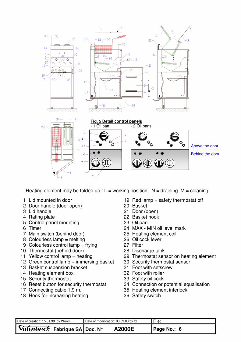
Heating element may be folded up : L = working position N = draining M = cleaning
1 Lid mounted in door 19 Red lamp = safety thermostat off 2 Door handle (door open) 20 Basket 3 Lid handle 21 Door (open) 4 Rating plate 22 Basket hook 5 Control panel mounting 23 Oil pan 6 Timer 24 MAX - MIN oil level mark 7 Main switch (behind door) 25 Heating element coil 8 Colourless lamp = melting 26 Oil cock lever 9 Colourless control lamp = frying 27 Filter
10 Thermostat (behind door) 28 Discharge tank 11 Yellow control lamp = heating 29 Thermostat sensor on heating element 12 Green control lamp = immersing basket 30 Security thermostat sensor 13 Basket suspension bracket 31 Foot with setscrew 14 Heating element box 32 Foot with roller 15 Security thermostat 33 Safety oil cock 16 Reset button for security thermostat 34 Connection or potential equalisation 17 Connecting cable 1,9 m. 35 Heating element interlock 18 Hook for increasing heating 36 Safety switch
Fig. 5 Detail control panels - 1 Oil pan - 2 Oil pans 8
9
Behind the door
Above the door 12
11
6 0
0
0 0 0
0
00 16
19 10 7

Date of creation: 15.01.98 by W/mm Date of modification: 03.09.03 by fd File:
Fabrique SA
Doc. N° A2000E Page No.: 7
4. Instructions for use
4.1 Pouring in oil
Grip lid [1] (Fig. 5, page 6) by handle [3] and place inside the door [21] (hinge at the top)
◊ Whilst working, the folded lid is supported inside the door.
Pour peanut oil into the fryer basin as far as the MAX level mark [24]
◊ Solid fat must first be melted in a pan, not on the heating element!
4.2 Operation : Melting - frying
Open door, move switch [7] to "Melt" position Switch thermostat to 150°, for example
⇒ Upper colourless signal lamp [8] on the right comes on. Reduced power for block of fat in fryer, also economic heating of oil, approx. 10-15 minutes.
⇒ Yellow signal lamp on the left comes on.
As soon as the first order is taken, turn switch [7] to "Fry". Switch thermostat to approx. 180°
⇒ Lower colourless lamp on the right comes on
⇒ Yellow "Heat" lamp comes on
⇒ The temperature reaches 180° in 2-3 minutes
As soon as the green cook light comes on, immerse basket
Set timer, e.g. 3 minutes. As soon as the timer sounds, raise basket, shake and suspend.
⇒ After half the frying time raise and shake basket. Do not knock against oil pan.
Always top up with oil after use. When the oil level is too low the power drops considerably and the oil is overheating. Never operate below the "MIN" oil level mark.
Never overfill basket. Follow filling stages 1, 2, 3 in table
• oil is cooled excessively
• frying time is extended
• the food being fried absorbs oil
Temp.
oC Food being fried Minutes Basket filling height
190 Deep frozen chips 3 (1+1) -1/3- 160 Prefrying raw chips 4 - 6 -3/4- 190 Finish frying, blanching chips 2 - 3 -1/3-
170 Veal pork schnitzel, cutlets 3 -1/2- 170 Deep frozen chicken legs 6 - 8 -1/2- 180 Fish 2 - 4 -1/2-
4.3 How to save oil ∗ Do not heat the fryer for hours before or after service (The heating time is only 5-6 minutes).
ÙÙÙÙ High temperatures ruin the oil, not the food!
∗ Limit oil temperature to 180 oC instead of 200
oC
ÙÙÙÙ Oil life is extended by approx. 40 % !
∗ After each service pour oil through a microfilter (optional extra). This retains even microscopic waste. Working time = 1 minute, including cleaning of filter !
otherwise
3/4
1/2
1/3

Date of creation: 15.01.98 by W/mm Date of modification: 03.09.03 by fd File:
Fabrique SA
Doc. N° A2000E Page No.: 8
4.4 Care of oil
Filter the oil after each use, approx. at 60°C. N.B: Risk of combustion!
Open door, turn main switch [7] to “ 0 ” position. Turn red lever [26] of oil cock complete downward, and at the same time push the safety pin to the right. Oil flows through the filter [27] into the tank [28]
⇒ Do not heat when oil pan is empty!
⇒ Is the cleaned filter on the tank ?
⇒ Pour oil back into the fryer.
⇒ Clean filter and tank.
Finally cover the oil pan with the lid mounted in the door. Frying basket is stainless.
⇒ The lid protects the oil from dust and light.
⇒ Is washed once a week.
* Important: If you do not open the drain cock completely (red lever in vertical position), the drain cock can be damaged!
4.5 Maintenance of fryer, changing oil
The fryer must be thoroughly cleaned when the oil is changed. As soon as the oil turns brown and begins to smoke (after approx. 20 to 40 operating hours, according to the operating temperature and grade of oil), the oil must be changed. Waste oil must not be poured into the drain. You must deliver waste oil to a disposal service.
Open door, turn main switch to “ 0 ”. Lift heating element into the drain position “ L ”. Drain oil, remove tank and clean filter.
⇒ Do not lift heating element fully, otherwise oil will run along the rod to the heating element box = additional cleaning.
Pour boiling water with a degreasing agent (soda) into the oil pan up to approx. 5 cm. above the "MAX" oil level mark. If you clean daily you will never have encrustation on the heating element or oil pan!
⇒ Allow the oil pan to operate for 1-2 hours, and clean heating element with a brush with a handle. Do not damage the thermostat sensor. Now raise heating element fully and clean oil pan down to the bottom. After cleaning, rinse thoroughly with hot water. Residues of cleaning agents or detergents ruin the fresh oil you are pouring in.
Wipe the oil pan and heating element clean with a dry cloth. Close oil cock, pour in fresh oil up to the “ MAX ” level [24]
⇒ Raise the heating element. Push back the interlock [35] and tilt the heating element fully down above the drain position.
Exclusive advantages of your Valentine fryer:
Higher power due to dialogue system (US + European patent)
⇒ When the green cook light comes on, immerse basket immediately. The thermostat does not switch off and the fryer is at maximum power.
Automatic saving (patent) ⇒ During the waiting time the fryer only heats at half power, saving oil and power.
Super heating ⇒ Very long heating elements, all in chromium steel, low loading, saves oil.
Thermostat ⇒ Reacts very quickly. Sensor in centre of oil pan.

Date of creation: 15.01.98 by W/mm Date of modification: 03.09.03 by fd File:
Fabrique SA
Doc. N° A2000E Page No.: 9
5. Repairs
5.1 Simple faults
Fault Possible cause Remedy The fryer is no longer heating. No lamp lights up The red lamp lights up
∗ No power
∗ Safety thermostat has switched off
◊ Check fuses, plugs and socket
◊ Press reset button (see 5.3)
The fryer is not heating sufficiently
∗ One phase is missing on the power supply cable
◊ Check fuses
The fryer is not heating sufficiently
∗ The switch has remained on "Melt"
◊ Turn button to "Fry"
Oil cock is sticking ∗ Sticking due to old oil residues
◊ Actuate frequently with hot oil. i.e. filter oil daily
The special mains cable must only be replaced by the manufacturer or his customer service representative.
5.2 Complex faults
Fault Possible cause Remedy The signal lamps come on, but the fryer is no longer heating
∗ Heating element defective ◊ Call the service centre *
The fryer is not heating sufficiently
∗ Interruption of a phase
∗ Heating element defective
◊ Call the service centre *
The fuses blow when fryer is switched on
∗ Short-circuiting ◊ Call the service centre *
The fault current safety switch (FI) in the fuse box switches off
∗ Moisture or poor insulation in the electrical circuit
◊ Call the service centre *
The colourless signal lamp does not come on or is flashing
∗ Main switch defective ◊ Call the service centre *
The yellow signal lamp does not come on or is flashing
∗ Thermostat defective ◊ Call the service centre *
The green signal lamp does not come on or is flashing
∗ Thermostat defective ◊ Call the service centre *
* Important: If you call the customer service dept, you must give the following information: Example:
- Type of fryer - Unit no. - Volts, amps, kilowatts
- V250 - U253A111K3 - 3x415V, 10.5A, 7.5kW
You will find this information on page 1 of these instructions and on the fryer rating plate.
If the information is correct the fitter gains time, the customer saves money!

Date of creation: 15.01.98 by W/mm Date of modification: 03.09.03 by fd File:
Fabrique SA
Doc. N° A2000E Page No.: 10
5.3 Safety thermostat
Every heating element is fitted with a breakage-proof temperature limiter. The reset button is located behind the door on the upper edge of the control panel. (Fig 5, no. 16, page 6). The red signal lamp [19] to the right of the reset button lights up as soon as the temperature limiter switches off. The safety thermostat ∗ when oil temperature is over 230
oC
breaks the heating circuit ∗ when capillary tube is damaged ∗ when temperature drops below 0
oC
and also in the case ∗ if fryer is heated without oil of improper use ∗ if the oil level is too low ∗ if you drain the oil before switching off the fryer
∗ If the heating element is not in the correct position in the oil pan
∗ if a block of fat is melted on the heating element
Resetting the safety thermostat Before resetting, find out why it has switched off (see above list). - Allow fryer to cool. The thermostat sensor on the heating element cannot be switched on if it
has not cooled down (to accelerate cooling raise heating element to the drain position). - Push the red button [16]. Lamp [19] will go out. N.B. Fryer is heating! If the safety thermostat
switches off again the fryer must be switched off. Inform the service centre.
5.4 Safety switch
As soon as the heating element is raised to the "drain" position the safety switch (Fig. 5, page 6, no. 36) interrupts the power supply.

Date of creation: 15.01.98 by W/mm Date of modification: 03.09.03 by fd File:
Fabrique SA
Doc. N° A2000E Page No.: 11
5.5 Spare parts
Only use original spare parts. When ordering spare parts indicate not only the unit no. but also the article no. given in the table. This information is given on page no. 1
Your fryer:
Name
V200
V200T
V2200
V2200T
V250
V250T
V2525
V2525T
V400
V400T
V600
Art. N
r.
Dia
gra
m
co
de
Tech
. data
Colourless control lamp (melt, fry) 2 2 4 4 2 2 4 4 2 2 2 6324 H3, H4, H8, H9
230V
Yellow control lamp (heat) 2 2 4 4 2 2 4 4 2 2 2 6325 H1, H6 230V
Green control lamp (immerse) 1 1 2 2 1 1 2 2 1 1 1 6326 H2, H7 230V
Red control lamp (Security) 1 1 2 2 1 1 2 2 2 2 3 6327 H5, H10, H15
230V
Resistance for control lamp 4 4 8 8 4 4 8 8 3 3 3 6328 R20 - R26
120K;2W
Safty temperatur limitor, sensor Ø4 1 1 2 2 1 1 2 2 2 2 3 6313-SA S1,S2,S3 20A
Working thermostat, sensor Ø4 1 2 1 2 1 1 6311-SA S20, S21 16A
Working thermostat, sensor Ø4 1 2 1 2 1 6310-SA S20, S21 16A
Safety switch XP-52 2 2 4 4 2 2 4 4 4 4 6 6321 S5 - S10 16A
Main switch 10A 42.04000.021 1 2 1 2 1 1 1 6316-52 S30 10A
Main switch 16A 43.34832.003 1 2 1 2 6317-51 S40,S41 16A
Connection terminal 20 EDS 4 4 4 4 4 4 4 6374-01 XT1 16mm²
Switch relay 3 x 20 A 2 2 3 6281-11 K1 - K3 3X20A
Fuse 6.3AT 5x20 mm 1 1 1 6402 F1 6.3AT
Fuseholder 1 1 1 6401 F1 FPG
Heating element
H E 7.2/7.5kW 3N400/415V 1 2 1 2 2 3 6291-SA
H E 11/11.8kW 3N400/415V 1 2 1 2 2 6302-SA
Miscellaneous
Timer 15 minutes 1 2 1 2 2 2 6341
Button for timer 15 min. 1 2 1 2 2 2 6335
Button for thermostat 110-190°C 1 2 1 2 1 1 6336
MELT - FRY button 1 2 1 2 1 1 6331
Ball cock 1"G (oil cock) 1 2 1 2 1 1 6431
Nut 1" G for oil cock 1 2 1 2 1 1 6432
Basket, filter
Basket V200 290 x 160 x H130 1 2 2 6417-02
Basket V250 290 x 210 x H130 1 2 6419-02
Basket V400 big 290 x 350 x H130 1* 6418-02 *(option)
Basket V600 small 290 x 255 x H130 2 6420-02
Basket V600 big 290 x 550 x H130 1* 6421-02 *(option)
Metal filter for drain tank V200 1 2 6427
Metal filter for drain tank V250 1 2 6428
Metal filter for drain tank V400 1 1 6429
Fryer type Type Unit number No. Voltage, current and power U, I, P
Contents
Page No.:
1. Important information ___________________________________________________ 3 1.1 Warning _____________________________________________________________________3 1.2 Risks from food remnants ______________________________________________________3 1.3 Periodic inspections ___________________________________________________________3
2.Technical data __________________________________________________________ 4 3. Installation_____________________________________________________________ 4 3.1 Electrical connection __________________________________________________________4 3.2 Installation examples
3.2.1 Installation example I (Fig. 1) _________________________________________________________ 4 3.2.2 Installation example II (Fig. 2)_________________________________________________________ 4 3.2.3 Installation example III (Fig. 3) ________________________________________________________ 4
3.3 Cleaning _____________________________________________________________________5
4. Instructions for use _____________________________________________________ 7 4.1 Pouring in oil _________________________________________________________________7 4.2 Operation - Melting - Frying _____________________________________________________7 4.3 How to save oil _______________________________________________________________7 4.4 Oil care ______________________________________________________________________8 4.5 Maintenance of fryer, changing oil _______________________________________________8
5. Repairs________________________________________________________________ 9 5.1 Simple faults _________________________________________________________________9 5.2 Complex faults________________________________________________________________9 5.3 Security thermostat___________________________________________________________10 5.4 Safety switch ________________________________________________________________10 5.5 Spare parts__________________________________________________________________11 5.6 Drawing marine legs __________________________________________________________12 5.6 Circuit diagram ______________________________________________________________13
Warning: The information given in these operating instructions may be amended at any time. Valentine Fabrique SA accepts no liability for errors in these instructions and any consequent damage. Date of creation: 15.01.98 by W/mm Date of modification: 10.09.01 by W/fd File:
Fabrique SA Doc. N° A2000B SO Page No.: 2

2. Technical data Model: V200 V200T V250 V250T V2200 V2200T V400 V400T V600 Power [kW] 7.2 11 7.2 11 14.4 22 14.4 22 21.6 Connection 3P+ E [A] 10 16 10 16 20 32 20 32 32 Frequency [Hz] 50 - 60 50 - 60 50 - 60 50 - 60 50 - 60 50 - 60 50-60 50-60 50-60 Security circuit cable SOLAS 4x1.5 4x1.5 4x1.5 4x1.5 4x1.5 4x1.5 4x1.5 4x1.5 4x1.5 Power connecting cable 4x1.5 4x1.5 4x1.5 4x1.5 4x2.5 4x4 4x2.5 4x4 4x4 Capacity in litres 7-9 7-9 8-10 8-10 2x 7-9 2x 7-9 18-20 18-20 25-28 Working thermostat 1 1 1 1 2 2 1 1 1 Security thermostat 1 1 1 1 2 2 2 2 3 Timer 1 1 1 1 2 2 1 1 1
Chips fried kg / h 19-23 26-32 19-23 26-32 38-46 52-64 38-46 52-64 57-68
Protective system IP X4 IP X4 IP X4 IP X4 IP X4 IP X4 IP X4 IP X4 IP X4 Weight [kg] 34 35 35 36 52 53 49 50 69 Dimensions [cm] 20x58x85 20x58x85 25x58x85 25x58x85 40x58x85 40x58x85 40X58X85 40X58X85 60X58X85
3. Installation Erect fryer, to level rotate the setscrews underneath the front feet. The fryer must not stand on combustible surfaces. Local safety regulations must be complied with.
N.B.: The slimline fryers V200 and V200T, as well as V250 and V250T, must not be freely erected (risk of tipping over). They must be installed between 2 units of furniture, or they must be supported on the sides.
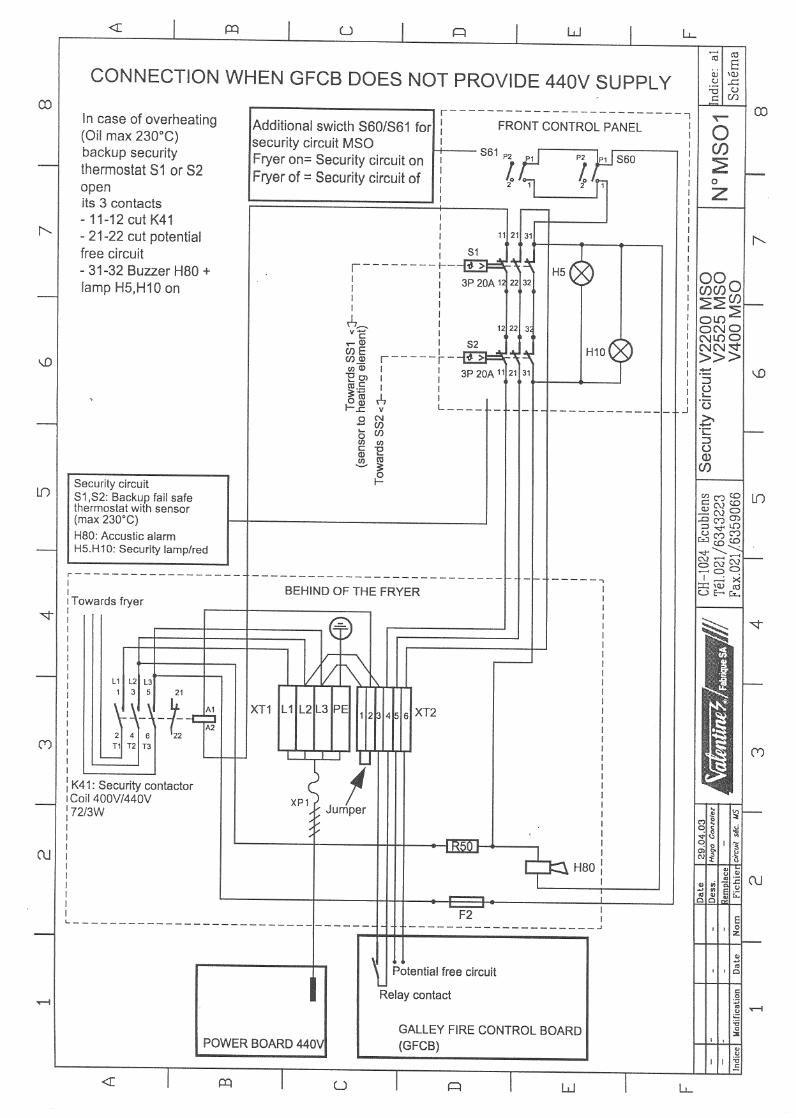
3.1 Electrical connection for Valentine Fryers in SOLAS version Only experts may connect and commission the fryers. Your mains data (voltage, current, fuse protection) must conform to the data on the fryer rating plate (The rating plate is mounted on the inside of the door (Figs. 1 to 3 = D).
Valentine Marine Fryers in SOLAS version are equipped with 2 cables: a) Security circuit cable Terminals 1 2 3 4 (see Circuit diagram, page 12) Terminals 1 + 2 need power from main galley to activate contactor K4. Circuit passes all security thermostats. Terminals 3 + 4 potential free contact in series over all security thermostats (for ex.: to connect alarms, flashing lights, horns, etc. on the main galley).
b) Power connecting cable Terminals L1 L2 L3 (see Circuit diagram, page 12)
The electrical connection must conform to local regulations, essentially as follows : - Fitting a mains plug on the connecting cable. Earth conductor = yellow/green, Phase sequence is immaterial. - Any fixed connection must be made via a mains switch with all-pole isolation (min. contact distance 3 mm.). - Before connection is made to the mains, check that the main switch "E" of the fryer is in the "0" position. Never heat without oil !
3.2 Installation examples A considerable amount of steam is generated when preparing chips. A good steam extractor is strongly recommended.
3.2.1 Installation example I (Fig. 1) Wall socket [F] resistant to dripping water IP X2 or water spray IP X4
3.2.2 Installation example II (Fig. 2) Fryer free-standing or next to cooking range. Connection column [H] with socket IP X2 or IP X4
3.2.3 Installation example III (Fig. 3) Connection box [J] with 3P+N isolating switch arranged above fryer. Cable permanently connected. Because of the considerable steam generated the box must be watertight IP X5. Date of creation: 15.01.98 by W/mm Date of modification: 10.09.01 by W/fd File:
Fabrique SA Doc. N° A2000B SO Page No.: 4

3.3 Cleaning Pull the fryer forward [K] to clean the rear wall and bottom (Fig. 4). The cable must therefore be long enough to do this.
Fig. 1: Fryer against wall Fig. 2: Fryer free-standing Fig. 3: Fryer against wall, with socket IP X2 (next to cooking range) with swichbox IP X5 N.B.: The V200 and V20 fryers, which are only 200 and 250 mm wide respectively, must be
secured on the sides (risk of tipping over).
A Steam extractor F Wall socket IP X2 B Wall G Connecting cable 1,9 m C Heating element folded up H Connection column (cleaning) J Connection box with isolating switch IP X5 D Rating plate with unit no. K Fryer pulled forward for cleaning the rear E Main switch behind door wall and bottom

92501BS HEATING ELEMENT SINGLE PHASEfor the 83/BS model
92401BS HEATING ELEMENT THREE PHASEfor the 83/BS model
______________________________________________________________________________________________________________________________
310101 HEATING ELEMENT THREE PHASEfor the Zenith Fryer
______________________________________________________________________________________________________________________________
62911SA HEATING ELEMENT THREE PHASEfor the V Series
FIRST CHOICE CATERING SPARES LTDPart No Description Alternative Codes
Tel: 01543 577778 Fax: 01543 504141 Email: [email protected] web: www.firstchoice-cs.co.uk
Electric Elements
VALENTINE

63023SA HEATING ELEMENT THREE PHASEfor the V Series Turbo only
______________________________________________________________________________________________________________________________
320104 OPERATING THERMOSTATfor the 83/BS model
320102 OPERATING THERMOSTATfor the Zenith - standard models
6311 OPERATING THERMOSTATfor the V Series
320101 SAFETY THERMOSTATfor Zenith auto reset style - A-C models
______________________________________________________________________________________________________________________________
70502 SAFETY THERMOSTATfor the Zenith (D models onwards)
______________________________________________________________________________________________________________________________
631451 SAFETY THERMOSTATfor the V Series
Part No Description Alternative Codes
FIRST CHOICE CATERING SPARES LTD
Tel: 01543 577778 Fax: 01543 504141 Email: [email protected] web: www.firstchoice-cs.co.uk2
Elements/Thermostats
VALE
NTIN
E
NOTE These OEM thermostats have been calibrated by Valentine Fabrique in Switzerland to reduce the power consumption to the elements in stages just prior to the maximum oil temperature being reached. By reducing the element power, the oil temperature will not excessively overheat. The calibrated 7th pin on these thermostats is also used to operated the temperature indicating lamp that has been fitted to Valentine fryers since the 1980’s. If the correct thermostat is not fitted the user will not be aware of when the oil has reached the correct temperature.

631652 ON-OFF-MELT-FRY SELECTOR SWITCHfor the V Series
______________________________________________________________________________________________________________________________
719 ON/OFF SELECTOR SWITCH0-1 0-1 positionscontact capacity 16A, 250VD spindle 6x4.6
______________________________________________________________________________________________________________________________
3278 ELEMENT CUT-OUT SWITCHfor the Zenith
______________________________________________________________________________________________________________________________
6336 TEMPERATURE CONTROL KNOBfor the V Series
______________________________________________________________________________________________________________________________
6331 ON/OFF KNOBfor the V Series
______________________________________________________________________________________________________________________________
71202 THERMOSTAT KNOBfor Zenith
FIRST CHOICE CATERING SPARES LTDPart No Description Alternative Codes
Tel: 01543 577778 Fax: 01543 504141 Email: [email protected] web: www.firstchoice-cs.co.uk
Switches/Knobs
VALENTINE

6324 CLEAR LAMP COMPLETEfor the V Series
______________________________________________________________________________________________________________________________
6325 AMBER LAMP COMPLETEfor the V Series
______________________________________________________________________________________________________________________________
6326 GREEN LAMP COMPLETEfor the V Series
______________________________________________________________________________________________________________________________
6327 RED LAMP COMPLETEfor the V Series
______________________________________________________________________________________________________________________________
3269 LAMPHOLDERfor Zenith
______________________________________________________________________________________________________________________________
3270 CLEAR LENSfor Zenith
______________________________________________________________________________________________________________________________
3271 AMBER LENSfor Zenith
______________________________________________________________________________________________________________________________
3272 GREEN LENSfor Zenith
______________________________________________________________________________________________________________________________
731 LENS AMBERfor the 83/BS Model
______________________________________________________________________________________________________________________________
739 BULB/NEON2W, 220Vfor Zenith 1 and 3 phase models
Part No Description Alternative Codes
FIRST CHOICE CATERING SPARES LTD
Tel: 01543 577778 Fax: 01543 504141 Email: [email protected] web: www.firstchoice-cs.co.uk4
Lamps
VALE
NTIN
E

PAN UNIONfor the Zenith
______________________________________________________________________________________________________________________________
6431 DRAIN VALVEfor V Series
______________________________________________________________________________________________________________________________
DRAIN VALVE KIT FOR 83/BS MODELComprises
663 Block665 Slide668 Rod670 Knob
DRAIN VALVE KIT FOR ZENITHComprises
663 Block665 Slide3172 Rod670 Knob
______________________________________________________________________________________________________________________________
3172 DRAIN VALVE RODfor Zenith only
______________________________________________________________________________________________________________________________
670 KNOB FOR DRAIN VALVEfor Zenith
FIRST CHOICE CATERING SPARES LTDPart No Description Alternative Codes
Tel: 01543 577778 Fax: 01543 504141 Email: [email protected] web: www.firstchoice-cs.co.uk
Drainage
VALENTINE

680 FRYER BASKET - OVALfor the 83/BS Model.
______________________________________________________________________________________________________________________________
641704 FRYER BASKET 641702for V2200/V400
641904 FRYER BASKET 641902for V250
______________________________________________________________________________________________________________________________
3179 FRYER BASKET P1for the Zenith
______________________________________________________________________________________________________________________________
3180 FRYER BASKET P2for the Zenith
Part No Description Alternative Codes
FIRST CHOICE CATERING SPARES LTD
Tel: 01543 577778 Fax: 01543 504141 Email: [email protected] web: www.firstchoice-cs.co.uk6
Fryer Baskets
VALE
NTIN
E


![VULCAN HIGH SPEED DEEP FAT FRYER (ELECTRIC) › vulcan-website...Vulcan catering equipment (ptY)ltD [ 2 ] VULCAN HIGH SPEED DEEP FAT FRYER (ELECTRIC) GENERAL DATA: MANUFACTURER: Vulcan](https://static.fdocuments.us/doc/165x107/60c05ae5c355355f26327394/vulcan-high-speed-deep-fat-fryer-electric-a-vulcan-website-vulcan-catering.jpg)


