OPERATING INSTRUCTIONS EM61-MK2 DATA LOGGING … · 2. Geonics Limited EM61MK2xp Data Logging...
56
EM61MK2xp 1745 Meyerside Drive, Mississauga, Ontario, Canada L5T 1C6 Tel: (905) 670 9580 Fax: (905) 670 9204 E-mail: [email protected] Geonics Limited December, 2006 Version 1.01 EM61-MK2 DATA LOGGING SYSTEM FOR WINDOWS XP BASED FIELD COMPUTER OPERATING INSTRUCTIONS
Transcript of OPERATING INSTRUCTIONS EM61-MK2 DATA LOGGING … · 2. Geonics Limited EM61MK2xp Data Logging...
EM61MK2xp
1745 Meyerside Drive, Mississauga, Ontario, Canada L5T 1C6Tel: (905) 670 9580 Fax: (905) 670 9204
E-mail: [email protected]
Geonics Limited
December, 2006
Version 1.01
EM61-MK2 DATA LOGGING SYSTEMFOR WINDOWS XP BASED FIELD COMPUTER
OPERATING INSTRUCTIONS

Table of Contents
1. Introduction ................................................................................................ 1 1.1 Program Requirements ......................................................................... 2 1.2 Installing EM61MK2xp......................................................................... 2 1.3 Running EM61MK2xp Program............................................................. 2 1.4 Main Screen ....................................................................................... 3
Short description of Main Screen options ...............................................................3
2. Survey Setup ............................................................................................... 5
3. Logger Setup............................................................................................... 9
4. Set Port for GPS & Monitoring .................................................................... 13 4.1 GPS Port Setup.................................................................................. 13 4.1 Monitoring GPS Receiver Output ........................................................ 15
5. Display Options ........................................................................................ 19
6. Logging Data ............................................................................................ 21 6.1 Monitoring Mode .............................................................................. 21
Description of Monitoring Mode Options.............................................................24 6.2 Stand By Mode.................................................................................. 32 6.3 Logging Mode................................................................................... 34 6.4 Stand By Mode Field Options ............................................................. 36
Appendix A ....................................................................................................... 45 A.1 Description of Data File in EM61MK2xp Format................................... 45 A.2 Conversion Factors............................................................................ 48 A.3 Example of File in EM61MK2xp Format ............................................... 50
Appendix B ....................................................................................................... 51 B.1 Using the EM61MK2xp with a GPS Receiver ........................................ 51 B.2 Description of GGA and GSA Data Messages...................................... 52


1EM61MK2xp Data Logging System (DAS70-XP)
1. IntroductionThe Geonics EM61MK2xp Data Logging System (DAS70-XP) consists of a laptop field computer, data logging program EM61MK2xp, and associated cable to connect the computer to the Geonics EM61-MK2 instrument. The program EM61MK2xp is designed for a IBM PC compatible com-puter and MS Windows XP/2000 operating system.
The EM61MK2xp program acquires and records survey data from the EM61-MK2 system, under the control of the operator. It also records various field information such as survey line number (line name), starting station, increment, comments, etc. Readings are displayed in graphic and numeric mode. Readings are displayed in real time in mV. In addition, the program allows you to monitor the instrument output while data is not recorded. The EM61MK2xp program continuously monitors the condition of the instrument battery, without leaving the program. The EM61MK2 also provides the possibility of automatic nulling of the instrument output at any time during the survey.
The program allows the user to set the EM61-MK2 into a specific instrument mode of operation: AUTO, Wheel, or Manual modes. In AUTO mode readings can be automatically recorded in desired time intervals. In WHEEL mode readings are triggered by a counter installed at the EM61-MK2 wheel assembly, and in MANUAL mode readings are triggered manually by the operator.
The program supports the standard EM61-MK2 instrument as well as EM61-MK2 High Power unit. The program allows you to record data while using various EM61-MK2 antenna (1 x 0.5 m, 1 x 1 m, or 0.5 x 0.5 m sensors) and Geonics EM61HH-MK2 Hand Held sensor.
The EM61MK2xp will accept NMEA-0183 compatible data from a GPS receiver directly connected to an Allegro field computer. GPS data which are embedded in the EM61MK2xp data file can be processed later in the Geonics DAT61MK2 program. The connected GPS must be able to stream NMEA-0183 compatible messages. The EM61MK2xp uses two NMEA messages GGA and GSA. While message GGA is mandatory, the GSA string is used only to provide information related to the GPS signal quality during data collection.
The EM61MK2xp program records data together with a time stamp at each station. Data files cre-ated with this program can be used to position a survey according to locations recorded separately by a Global Positioning System (GPS).
Survey setup parameters are saved in a file, therefore they can be automatically used during subse-quent data collection sessions.
Data files are saved to the user selected data directory. Data file names, which can be set by the program based on the computer clock or user specified, have extension names R61. Files can be converted to M61 format and viewed in DAT61MK2 program.
Number of readings in a data file is limited only by the hard drive capacity, however it is strongly recomended to avoid huge data files (i..e one to two hours long data files are adequate). The maxi-mum speed of data collection is approximately 17 readings per second assuming 1 Hz (or less) GPS input. In graphic display mode, a profile containing the last 150 data readings is displayed for each channel.

2 Geonics Limited 3EM61MK2xp Data Logging System (DAS70-XP)
1.1 Program Requirements To successfully use this software, you will need :
Computer- PC field computer operating under Windows 2000 Pro, XP, or later,- Minimum 256 Mb of RAM memory, - CD drive or other mean to transfer files,- minimum 800 x 600 pixel display resolution, - serial Ports:
one serial port per instrument in array plus one serial port if directly connected GPS receiver is to be used (USB to multiple RS-232 ports and PCMCIA RS-232 adapters can be used).
Geonics EM61-MK2The EM61-MK2 instrument with associated cables.
The EM61MK2xp program is stored on DAT61MK2 CD disk. All necessary initial files (with extension names .INI) are created in your field computer after the program is run for the first time. Check that the file EM61MK2xp.EXE is included on the CD disk.
1.2 Installing EM61MK2xpThe program consists of a standalone file EM61MK2xp.exe, no DDLs nor other libraries are required to run this program. The program is usually installed during data processing program DAT61MK2 installation, it is placed in subdirectory LogData of the selected installation directory.
If the program file is included separately on the DAT61MK2 CD disk, or downloaded from e-mail server it can be installed by copying the EM61MK2xp.exe file to any directory on your hard disk. This can be performed by using Windows Explorer.
After you run the program for the first time it will create permanent initial files (.INI) which contain some of the program settings. If the above files do not exist on the default drive they will be created with default parameters during the first execution of the program.
The EM61MK2xp data files contain extension name R61 and their base names should be limited to 8 characters.
1.3 Running EM61MK2xp ProgramStart EM61MK2xp by double clicking the EM61MK2xp icon in the Start|Programs menu, in Windows Explorer, or on the desktop if a shortcut was created. At the start, EM61MK2xp displays the following screen.
The EM61MK2xp is a command button and dialog driven program. Command buttons can be executed by clicking with the left mouse button, or by pressing the indicated (underlined) character on the keyboard, or by using TAB to scroll through the buttons and ENTER to execute. In the Main Screen of the program Up and Down arrow keys can be also used to scroll through the buttons.

2 Geonics Limited 3EM61MK2xp Data Logging System (DAS70-XP)
The Main Screen appears always as the first window after the program is started. It contains the name of the program, its version number (right bottom corner), and list of command buttons with available options on the right side. The major , left portion of the window contains information about current survey and system settings. This section is updated in real time as soon as the program parameters are changed in dialogs.
1.4 Main ScreenThe Main Screen always appears after the program is started. It contains the name of the program, its version number, and a list of buttons representing the available options. The EM61MK2xp Main Screen is displayed below.
These options are selected by clicking on buttons, or from keyboard using TAB/ENTER or shortcuts indicated by underline label characters. In case of Main Screen buttons the Down and Up arrow keys and <ENTER> can be used as well.
Short description for each of the options follows.
Short description of Main Screen options
Monitor/Log This option allows to monitor and log the EM61-MK2 output. Monitor/Log screen starts always in Monitor mode, and then after a data file is created Logging mode is available. Monitor mode provides several options: the instrument nulling, performing Internal and External QC coil calibration, monitoring EM61-MK2 battery level, monitoring quality of GPS signal, etc.
4 Geonics Limited
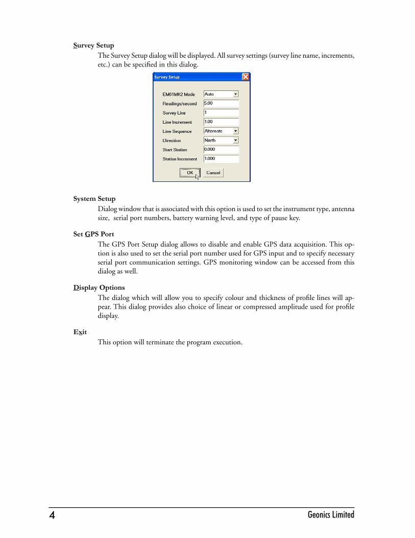
Survey SetupThe Survey Setup dialog will be displayed. All survey settings (survey line name, increments, etc.) can be specified in this dialog.
System SetupDialog window that is associated with this option is used to set the instrument type, antenna size, serial port numbers, battery warning level, and type of pause key.
Set GPS PortThe GPS Port Setup dialog allows to disable and enable GPS data acquisition. This op-tion is also used to set the serial port number used for GPS input and to specify necessary serial port communication settings. GPS monitoring window can be accessed from this dialog as well.
Display OptionsThe dialog which will allow you to specify colour and thickness of profile lines will ap-pear. This dialog provides also choice of linear or compressed amplitude used for profile display.
ExitThis option will terminate the program execution.
5EM61MK2xp Data Logging System (DAS70-XP)
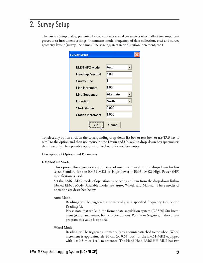
2. Survey SetupThe Survey Setup dialog, presented below, contains several parameters which affect two important procedures: instrument settings (instrument mode, frequency of data collection, etc.) and survey geometry layout (survey line names, line spacing, start station, station increment, etc.).
To select any option click on the corresponding drop-down list box or text box, or use TAB key to scroll to the option and then use mouse or the Down and Up keys in drop-down box (parameters that have only a few possible options), or keyboard for text box entry.
Description of Options and Parameters:
EM61-MK2 ModeThis option allows you to select the type of instrument used. In the drop-down list box select Standard for the EM61-MK2 or High Power if EM61-MK2 High Power (HP) modification is used. Set the EM61-MK2 mode of operation by selecting an item from the drop-down listbox labeled EM61 Mode. Available modes are: Auto, Wheel, and Manual. These modes of operation are described below.
Auto ModeReadings will be triggered automatically at a specified frequency (see option Readings/s). Please note that while in the former data acquisition system (DAS70) Stn Incre-ment (station increment) had only two options: Positive or Negative, in the current program this value is optional.
Wheel ModeReadings will be triggered automatically by a counter attached to the wheel. Wheel increment is approximately 20 cm (or 0.64 foot) for the EM61-MK2 equipped with 1 x 0.5 m or 1 x 1 m antennas. The Hand Held EM61HH-MK2 has two

6 Geonics Limited 7EM61MK2xp Data Logging System (DAS70-XP)
wheel increments 0.1 and 0.2 m. Check the wheel increment setting on the an-tenna assembly. When Wheel mode is selected option Reading/second is not available, see figure below. Please note that while in former data acquisition system (DAS70) Stn Increment (station increment) had only two options: Positive or Negative, in the current program this parameter is optional and its value has to be entered accord-ing to used wheel increment.
Manual ModeReadings will be taken only while the manual trigger (switch on the logger cable) is pressed. This mode may be used only in very specific applications since the highly dynamic EM61-MK2 response requires finely spaced data points. Please note that when Manual mode is selected option Reading/second is not available.

6 Geonics Limited 7EM61MK2xp Data Logging System (DAS70-XP)
Readings/secondWhen this option is available (only in Auto mode) activate text box by clicking with a mouse or using TAB key and then enter desired value.This parameter describes number of readings per second that will be taken. Any number larger than zero can be entered, however the EM61-MK2 maximum frequency of data output is 17 readings per second.
Survey Line (survey line name)Activate text box by clicking with a mouse left button or using TAB key and then enter desired name (number) for the survey line.This is a user’s tag number/name for the profile line. The length of the name can not exceed 8 characters. The line name is usually used as a coordinate perpendicular to the survey lines direction. For example, when survey lines are laid out along W-E direction stations describe W-E coordinate, while Line names may describe S-N (vertical on a map) coordinate.
Line Incr. (survey line name)Activate text box by clicking with a mouse or using TAB key and then enter desired for the survey line increment.This parameter specifies the distance by which survey lines will be separated. This setting will be used to determine number (name) of the next survey line.
SequenceWhen this option is highlighted and drop-down box is expanded use mouse or use Down or Up cursor key to toggle between two available settings: Alternate and One Way.
Alternate is used when neighboring lines are surveyed in the opposite direction, which is the most common procedure during field surveys. One Way is used when each survey line is traversed in the same direction.The choice of this parameter will affect the default start station, a signature of the station increment, and line direction when parameters for the next survey lines is determined.

8 Geonics Limited
DirectionClicking on the down arrow next to the text box opens a drop-down box showing the avail-able options, or when the keyboard is used activate the text box and then by using up or down arrow keys select one of four available settings: East, West, South, and North.This parameter indicates the heading of the survey line.
Start Station (start station of a survey line)Activate text box by clicking or using TAB key and then enter the desired value for the start station.This parameter specifies the starting station number for the selected survey line. This value is used in conjunction with Station Increment to calculate the current station number for display purposes.
Stn Increment (station increment)Activate text box by clicking with a mouse or using TAB key and then enter the desired value for the station increment.This parameter specifies the station increment for the selected survey line. This value is used in conjunction with Start Station to calculate the current station number for display purposes.
After all the parameters in the Survey Setup dialog are updated click on the button OK or press ENTER key to accept the displayed settings. The program will return to the Main Screen. Updated settings will be written to the initial file and they will be given as default parameters in the subse-quent Survey Setup dialog.
To return to original settings (state before this dialog was selected) click on the Cancel (X) button or press Esc key. All parameters will be reset to initial settings and the program will return to the Main Screen.
9EM61MK2xp Data Logging System (DAS70-XP)
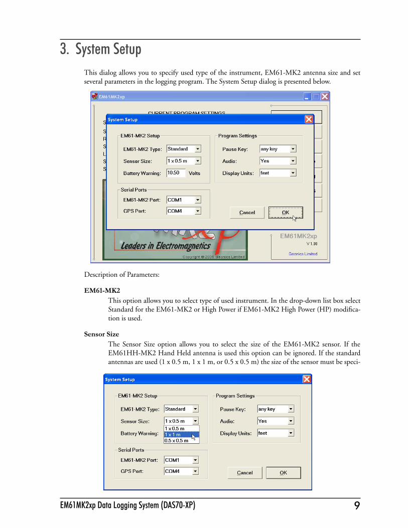
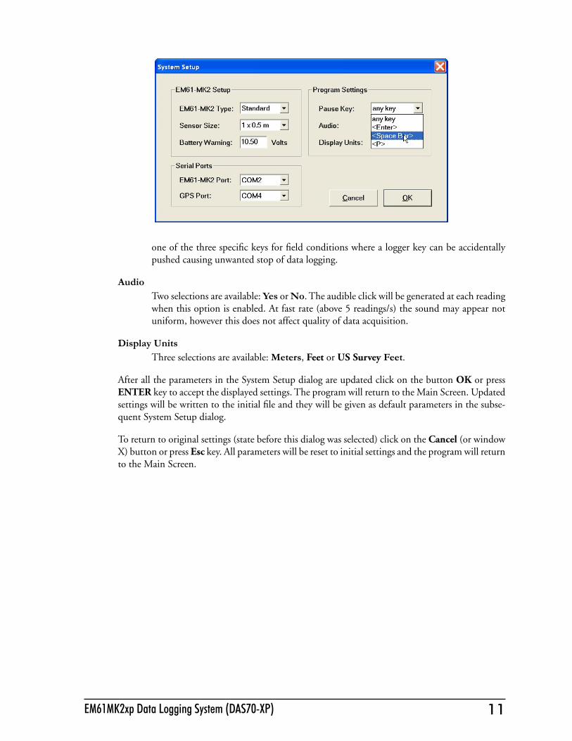
3. System SetupThis dialog allows you to specify used type of the instrument, EM61-MK2 antenna size and set several parameters in the logging program. The System Setup dialog is presented below.
Description of Parameters:
EM61-MK2This option allows you to select type of used instrument. In the drop-down list box select Standard for the EM61-MK2 or High Power if EM61-MK2 High Power (HP) modifica-tion is used.
Sensor SizeThe Sensor Size option allows you to select the size of the EM61-MK2 sensor. If the EM61HH-MK2 Hand Held antenna is used this option can be ignored. If the standard antennas are used (1 x 0.5 m, 1 x 1 m, or 0.5 x 0.5 m) the size of the sensor must be speci-

10 Geonics Limited 11EM61MK2xp Data Logging System (DAS70-XP)
fied before monitoring the instrument output. Select proper size of the EM61-MK2 sensor in the drop-down list box labeled Sensor Size.
Battery WarningSpecify instrument battery warning level. When the EM61-MK2 battery voltage will reach and drop below specified value the program will display battery voltage on the red background.
EM61 PortThe number of serial port that is assigned to the EM61-MK2. Available selections: COM1 to COM12. The program default is COM1. Communication parameters for the selected serial port are set by the program, since the EM61-MK2 operates at fixed settings: Baud Rate (9600), Parity (N), Data Bits (8), and Bit Stop (1).This port must be different than the port specified in the list box "GPS Port:" (see below) or in the GPS Port Setup dialog window (see chapter 4), otherwise a message will be displayed and ports will have to be reassigned.Select port number in the drop-down list box (see Figure below).
GPS PortThe number of serial port that is assigned to the GPS receiver. Available selections: COM1 to COM12. The program default is COM2. Communication parameters for the selected serial port can be set in GPS Port Setup dialog. The GPS port can be also assigned in the latter dialog.This port must be different than the port specified as the EM61-MK2 serial port.Select port number in the drop-down list box similarly to EM61-MK2 port assignment procedure.
Pause keyFour selections are available: any key, Space Bar, Enter, and P This feature is used to pause data recording during logging session. Default setting any key can be changed to
10 Geonics Limited 11EM61MK2xp Data Logging System (DAS70-XP)
one of the three specific keys for field conditions where a logger key can be accidentally pushed causing unwanted stop of data logging.
AudioTwo selections are available: Yes or No. The audible click will be generated at each reading when this option is enabled. At fast rate (above 5 readings/s) the sound may appear not uniform, however this does not affect quality of data acquisition.
Display UnitsThree selections are available: Meters, Feet or US Survey Feet.
After all the parameters in the System Setup dialog are updated click on the button OK or press ENTER key to accept the displayed settings. The program will return to the Main Screen. Updated settings will be written to the initial file and they will be given as default parameters in the subse-quent System Setup dialog.
To return to original settings (state before this dialog was selected) click on the Cancel (or window X) button or press Esc key. All parameters will be reset to initial settings and the program will return to the Main Screen.

13EM61MK2 Data Logging System (DAS70-CX)
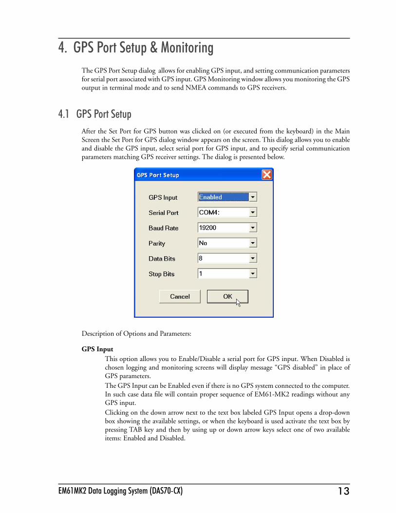
4. GPS Port Setup & MonitoringThe GPS Port Setup dialog allows for enabling GPS input, and setting communication parameters for serial port associated with GPS input. GPS Monitoring window allows you monitoring the GPS output in terminal mode and to send NMEA commands to GPS receivers.
4.1 GPS Port SetupAfter the Set Port for GPS button was clicked on (or executed from the keyboard) in the Main Screen the Set Port for GPS dialog window appears on the screen. This dialog allows you to enable and disable the GPS input, select serial port for GPS input, and to specify serial communication parameters matching GPS receiver settings. The dialog is presented below.
Description of Options and Parameters:
GPS InputThis option allows you to Enable/Disable a serial port for GPS input. When Disabled is chosen logging and monitoring screens will display message “GPS disabled” in place of GPS parameters.The GPS Input can be Enabled even if there is no GPS system connected to the computer. In such case data file will contain proper sequence of EM61-MK2 readings without any GPS input.Clicking on the down arrow next to the text box labeled GPS Input opens a drop-down box showing the available settings, or when the keyboard is used activate the text box by pressing TAB key and then by using up or down arrow keys select one of two available items: Enabled and Disabled.

14 Geonics Limited 15EM61MK2 Data Logging System (DAS70-CX)
Serial PortThe number of serial port that is assigned to the GPS input. Available selections: COM1 to COM12. The program default is COM2. Communication parameters for the selected serial port can be determined in options described below.
This port must be different than the port specified in the System Setup menu (for EM61-MK2), otherwise a message will be displayed and ports will have to be reassigned.Clicking on the down arrow next to the text box labeled Serial Port opens a drop-down box showing the available ports, or when the keyboard is used activate the text box by pressing TAB key and then by using up or down arrow keys select one of available items.
Baud RateSpecify Baud Rate for the output port, the selected value should match the Baud Rate of the GPS system, default is 9600. Available settings are: 4800, 9600, 19200, 38400, 57600, and 115200.

14 Geonics Limited 15EM61MK2 Data Logging System (DAS70-CX)
Clicking on the down arrow next to the text box labeled Baud Rate opens a drop-down box showing the available parameters, or when the keyboard is used activate this text box by pressing TAB key and then by using up or down arrow keys select one of available items.
ParitySelect Parity for the output port, the parameter should much the Parity set in the GPS serial port settings. Available settings are None, Even, and Odd; default is N.Clicking on the down arrow next to the text box labeled Parity opens a drop-down box showing the available parameters, or when the keyboard is used activate this text box by pressing TAB key and then by using up or down arrow keys select one of available items.
Data BitsSpecify Data Bits for the output port, the selected value should much settings in the GPS receiver, default is 8. Other available selection is 7.Clicking on the down arrow next to the text box labeled Data Bits opens a drop-down box showing the available parameters, or when the keyboard is used activate this text box by pressing TAB key and then by using up or down arrow keys select one of available items.
Stop BitsSpecify Stop Bits for the output port, the selected value should much settings in the GPS receiver, default is 1. Available selections are 1 or 2.Clicking on the down arrow next to the text box labeled Stop Bits opens a drop-down box showing the available parameters, or when the keyboard is used activate this text box by pressing TAB key and then by using up or down arrow keys select one of available items.
After all the parameters in the GPS Port Setup dialog are updated click on the button OK or press ENTER key to accept the displayed settings. The program will return to the Main Screen. Updated settings will be written to the initial file and they will be given as default parameters in the subse-quent Survey Setup dialog.
To return to original settings (state before this dialog was selected) click on the Cancel (X) button or press Esc key. All parameters will be reset to initial settings and the dialog window will disappear.
4.2 Monitoring GPS Receiver OutputAfter the Main Screen command button GPS Monitoring is clicked or executed by the keyboard the program will display the GPS Monitoring window in terminal mode. In this mode the screen is divided into three parts. The terminal window in the top portion of the screen displays the GPS receiver output. The middle portion labeled NMEA Command is used to display entered NMEA commands previously sent to the GPS receiver, and at the bottom, command buttons with avail-able options (Pause/Go, Send, and Exit) is displayed. These buttons can be clicked on, executed by TAB key and ENTER keys, or by using shortcuts (pressing underlined letter keys). This screen is shown below.

16 Geonics Limited 17EM61MK2 Data Logging System (DAS70-CX)
As soon as the EM61MK2xp screen is in terminal mode and the GPS is streaming data, each mes-sage transmitted by GPS receiver will appear in the top portion of the display (the end may be cut off if an NMEA message is longer than screen). The display is updated with the frequency the GPS receiver outputs data. This allows you to recognize the GPS update rate and type of messages being sent by the connected GPS. In cases where the GPS data is not received by the logger a message NO DATA and current time will appear in the top window of the display, as shown below.
The message NO DATA is normally updated with a rate of 7 seconds. This may indicate the following: serial port number not correctly specified in Set Port for GPS dialog, GPS receiver not sending any data, and not working or not connected GPS receiver. If the message is updated more often than 7 seconds (i.e. every 1 or 2 seconds) or the display does not show legible characters, it is possible that the GPS is working correctly and is connected to the proper serial port, however communication parameters are not specified correctly. In most cases the Baud Rate or Parity must be adjusted.
The NO DATA message may also appear if the GPS data are received correctly, but the GPS receiver was set to send data with a time interval longer than 7 seconds. In this case the NO DATA mes-sage will be displayed in between GPS messages. This indicates that the GPS is working correctly, however the operator should consider adjustment of the GPS receiver output update rate. Most high resolution geophysical surveys require positioning update of 1 or 2 seconds, and a 5 seconds interval can be used only when the survey is carried out at an even pace and along relatively straight survey lines.
The monitoring display can be stopped any time by using button labeled Pause. At that time scrolling of the GPS output will be stopped, and the button will be labeled Go. The next click (or keyboard
action) on this button will activate receiving and display of GPS data.
The button labeled Send allows you to send a NMEA command to the GPS receiver. It is preferable if the GPS receiver parameters are set using the GPS manufacturer software or controller (GPS logger or panel keys). However, when the operator is familiar with NMEA protocol and structure of commands for a given GPS system, this function can be very convenient and useful when the update rate and enabling or disabling messages in the data stream is required.
After the button Send is clicked a dialog titled GPS Message is displayed and the beginning of the standard NMEA command, $PASHS, or the last entered command is displayed. After the entire NMEA command is typed in, click OK button or press the key <ENTER> to send the command to the GPS receiver. Clicking the Cancel button or pressing the <Esc> key will cancel the command and hide the NMEA Message dialog. An example of a command that will enable the NMEA message SAT is given in the below figure (it is assumed that the GPS receiver output serial port is A).
16 Geonics Limited 17EM61MK2 Data Logging System (DAS70-CX)
After this command is received by the GPS receiver, the confirmation message will be send by the receiver ($PASHR, ACK*3D) and data stream will contain the message SAT ($PASHR, SAT,..... in the above figure).
Please note, that not every GPS system accepts and uses the same standard set of NMEA commands and messages. In addition, some GPS systems do not accept commands sent by the serial port at all. The configuration of these type of receivers can be updated only by the controlling device (usually GPS logger, controller, or the receiver panel keys).

18 Geonics Limited
19EM61MK2xp Data Logging System (DAS70-XP)
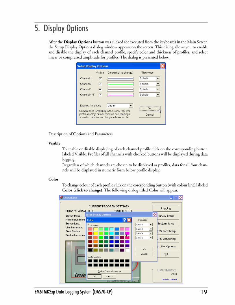
5. Display OptionsAfter the Display Options button was clicked (or executed from the keyboard) in the Main Screen the Setup Display Options dialog window appears on the screen. This dialog allows you to enable and disable the display of each channel profile, specify color and thickness of profiles, and select linear or compressed amplitude for profiles. The dialog is presented below.
Description of Options and Parameters:
VisibleTo enable or disable displaying of each channel profile click on the corresponding button labeled Visible. Profiles of all channels with checked buttons will be displayed during data logging.Regardless of which channels are chosen to be displayed as profiles, data for all four chan-nels will be displayed in numeric form below profile display.
ColorTo change colour of each profile click on the coresponding button (with colour line) labeled Color (click to change). The following dialog titled Color will appear.
20 Geonics Limited
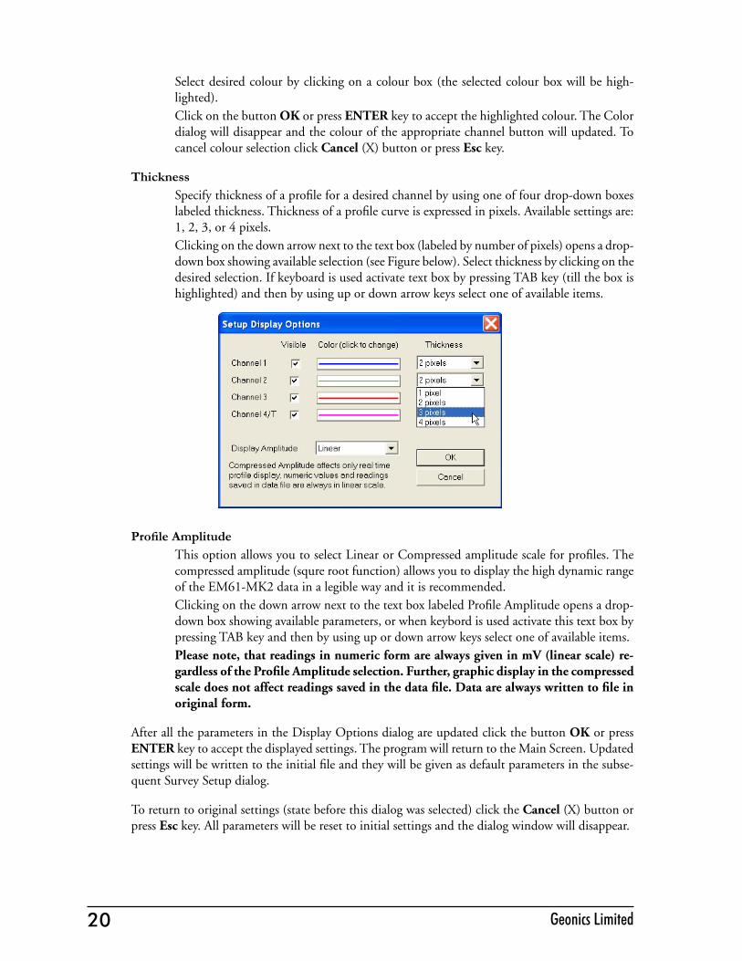
Select desired colour by clicking on a colour box (the selected colour box will be high-lighted). Click on the button OK or press ENTER key to accept the highlighted colour. The Color dialog will disappear and the colour of the appropriate channel button will updated. To cancel colour selection click Cancel (X) button or press Esc key.
ThicknessSpecify thickness of a profile for a desired channel by using one of four drop-down boxes labeled thickness. Thickness of a profile curve is expressed in pixels. Available settings are: 1, 2, 3, or 4 pixels.Clicking on the down arrow next to the text box (labeled by number of pixels) opens a drop-down box showing available selection (see Figure below). Select thickness by clicking on the desired selection. If keyboard is used activate text box by pressing TAB key (till the box is highlighted) and then by using up or down arrow keys select one of available items.
Profile AmplitudeThis option allows you to select Linear or Compressed amplitude scale for profiles. The compressed amplitude (squre root function) allows you to display the high dynamic range of the EM61-MK2 data in a legible way and it is recommended. Clicking on the down arrow next to the text box labeled Profile Amplitude opens a drop-down box showing available parameters, or when keybord is used activate this text box by pressing TAB key and then by using up or down arrow keys select one of available items.Please note, that readings in numeric form are always given in mV (linear scale) re-gardless of the Profile Amplitude selection. Further, graphic display in the compressed scale does not affect readings saved in the data file. Data are always written to file in original form.
After all the parameters in the Display Options dialog are updated click the button OK or press ENTER key to accept the displayed settings. The program will return to the Main Screen. Updated settings will be written to the initial file and they will be given as default parameters in the subse-quent Survey Setup dialog.
To return to original settings (state before this dialog was selected) click the Cancel (X) button or press Esc key. All parameters will be reset to initial settings and the dialog window will disappear.

21EM61MK2 Data Logging System (DAS70-CX)
6. Logging DataAfter the Logging button (in Main Screen) is clicked or executed by the keyboard, the program enters the logging session which contains three modes: Monitoring, Stand By and Logging. The program starts the logging session always in Monitoring mode. In this mode EM61-MK2 readings
and GPS parameters can be quickly examined and some functions (creating data file, nuling, QC coil check) can be performed. After a data file is created in Monitoring mode, the program switches to Stand By mode and allows access to Logging mode. In Stand By mode instrument output can be monitored and some survey and logging parameters can be changed, and Logging mode is used only to record data. Two modes Stand By and Logging are toggled by GO and Pause buttons.
6.1 Monitoring ModeThe Monitor mode allows initial inspection of the range of the instrument readings at a particular site, monitoring the instrument performance, quick inspection of the condition of the instrument battery, perform QC Coil check, and setting zero level of the instrument.
It is assumed that the instrument is turned ON prior to using this option. If the instrument is OFF or the instrument console is not connected to the computer the following message shown below will appear.

22 Geonics Limited 23EM61MK2 Data Logging System (DAS70-CX)
Check the connection or turn the instrument ON and select the Monitor/Log option again.
Assuming that the instrument works properly the program will display the Monitor mode window and will start normalization session which lasts less than 10 seconds. After the normalization is finished the layout of the Monitor window is as follows:
The Monitor (as well as Stand by and Logging) window is divided into five sections.
One line of text in the top section provides survey parameters (used in Stand By and Logging modes) and instrument information. In Monitor mode this section displays: instrument mode (4 or D), current display mode (Monitor, Stand By or Logging), Allegro battery level (in % of full charge),

22 Geonics Limited 23EM61MK2 Data Logging System (DAS70-CX)
and the EM61-MK2 battery level in Volts (following label B:). When fiducial marker is pressed then M is displayed.
The second, largest graphic section will be used to display profiles during logging data. Numeric labels on the right side of profile window correspond to scale minimum (below the profile window) and maximum (above the profile window).
The remaining bottom section contains a window with current EM61-MK2 readings, three frames (File Parameters, Line Parameters, and GPS information), and command buttons located on the right side of the screen.If Mode 4 was selected on the instrument panel (it is displayed at the top of the screen) channels 1, 2, 3, and 4 will be displayed under profile window, and when Mode D was selected (for Top and Bottom antennas) channels 1, 2, 3, and T will be given as labels in numeric window. The EM61-MK2 readings are updated approximately 10 times per second during the monitoring session.
When GPS is Disabled in the Set GPS Port dialog a message GPS Disabled will be displayed. If the GPS port is Enabled and a working GPS receiver is connected to the field computer the Monitoring screen will display GPS parameters, as presented below.
In the above Figure one line of the display is dedicated to show the GPS status. A label Positions will be used during data acquisition, it will provide the number of GPS positions saved in the data file. Below, two lines display the parameters describing the quality of GPS positions. A label DGPS (Differential Global Positioning System) indicates that GPS readings are differentially corrected in real time, while label AGPS (Autonomous Global Positioning System) indicates lack of differential correction. On the right side of DGPS or AGPS label two green and white circles alternate. These two circles should alternate colours with the frequency of GPS update rate (usually 1 second inter-vals). If the circles do not change colours for long periods of time it means that the GPS system is not working or that it is not connected to the field computer. The next label PDOP with a value varying between 0 and 99.9 represents an index called Position Dilution of Precision (PDOP). This value is available only when messages both, GGA and GSA are received from GPS. The last label Sat and following number shows number of currently tracked satellites. Refer to section 4 (Set Port for GPS), Appendix B, and to GPS manuals for more information about GPS parameters. Two
24 Geonics Limited 25EM61MK2 Data Logging System (DAS70-CX)
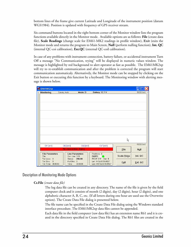
bottom lines of the frame give current Latitude and Longitude of the instrument position (datum WGS1984). Position is updated with frequency of GPS receiver stream.
Six command buttons located in the right bottom corner of the Monitor window lists the program functions available directly in the Monitor mode. Available options are as follows: File (create data file), Scale Readings (change scale for EM61-MK2 readings in profile window), Exit (exits the Monitor mode and returns the program to Main Screen, Null (perform nulling function), Int. QC (internal QC-coi calibration), Ext.QC (external QC-coil calibration).
In case of any problems with instrument connection, battery failure, or accidental instrument Turn Off a message "No Communication, trying" will be displayed in numeric values window. The message is highlighted by red background to alert operator as fast as possible. The EM61MK2xp will try to re-establish communication and after the problem is corrected the program will start communication automaticaly. Alternatively, the Monitor mode can be stopped by clicking on the Exit button or executing this function by a keyboard. The Monitoring window with alerting mes-sage is shown below.
Description of Monitoring Mode Options
Cr.File (create data file)The log data file can be created in any directory. The name of the file is given by the field computer clock and it consists of month (2 digits), day (2 digits), hour (2 digits), and one alphabetic character A, B, C, etc. (If all letters during one hour are used use the Overwrite option). The Create Data File dialog is presented below.The file name can be specified in the Create Data File dialog using the Windows standard interface procedure. The EM61MK2xp data files cannot be appended. Each data file in the field computer (raw data file) has an extension name R61 and it is cre-ated in the directory specified in Create Data File dialog. The R61 files are created in the

24 Geonics Limited 25EM61MK2 Data Logging System (DAS70-CX)
instrument binary format. These files can be also converted to ASCII format and processed in the Geonics DAT61MK2 program. After the file is specified click on the button OK or press ENTER key to accept and create data file. The program will switch Monitor mode to Stand By mode and the data file will be displayed on the screen. To cancel selection and return to Monitoring mode tap the Cancel (X) button or press Esc key.
NullTo perform a null of the instrument click on the button labeled Null or execute this option using the keyboard (navigate to the button by pressing TAB key and when highlighted press ENTER key, or use shortcut - press key U). At this moment the computer takes 50 readings and calculates the instrument offset.

26 Geonics Limited 27EM61MK2 Data Logging System (DAS70-CX)
The calculated offset is applied to all the readings that follow this operation. If needed, this procedure can be repeated several times until satisfactory results are obtained. However, there is no associated “Undo” function. If original values (without calculated offsets) of the EM61-MK2 readings are needed, exit the EM61MK2 program and run it again. The EM61-MK2 instrument does not have to be turned OFF. Null operation can be also per-formed later during data collection.
Int.QC (Internal QC Coil Calibration)The Internal QC coil calibration is described in detail in the EM61-MK2 Operating Instructions.To start the calibration using Internal QC coil click on the key labeled Int. QC or execute this option by keyboard (navigate to the button by pressing TAB key and when highlighted press ENTER key, or use shortcut - press key I). This action begins by performing the auto-matic nulling which in this case is only in effect for the duration of the calibration process. It will not affect EM61-MK2 readings. After the nulling is completed (less than 5 seconds) the Internal QC coil Calibration window is displayed. All command buttons in the bottom right corner of logging windows are disabled during Calibration procedure.
When Calibration window is displayed please use keyboard keys (O or C) rather than a mouse to execute buttons labeled OK and Cancel. Clicking on buttons by mouse will work, however several mouse button clicks may be required.After OK button is clicked (or shortcut key O is pressed) the window displays timer with elapsed seconds and EM61-MK2 readings. This display lasts for 60 seconds. During this time please follow the instructions provided on the Allegro screen.
26 Geonics Limited 27EM61MK2 Data Logging System (DAS70-CX)
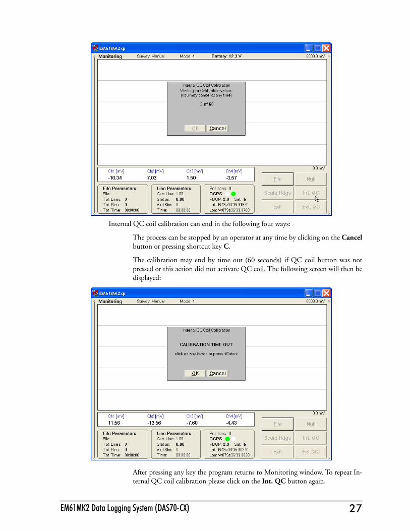
Internal QC coil calibration can end in the following four ways:
The process can be stopped by an operator at any time by clicking on the Cancel button or pressing shortcut key C.
The calibration may end by time out (60 seconds) if QC coil button was not pressed or this action did not activate QC coil. The following screen will then be displayed:
After pressing any key the program returns to Monitoring window. To repeat In-ternal QC coil calibration please click on the Int. QC button again.
28 Geonics Limited 29EM61MK2 Data Logging System (DAS70-CX)
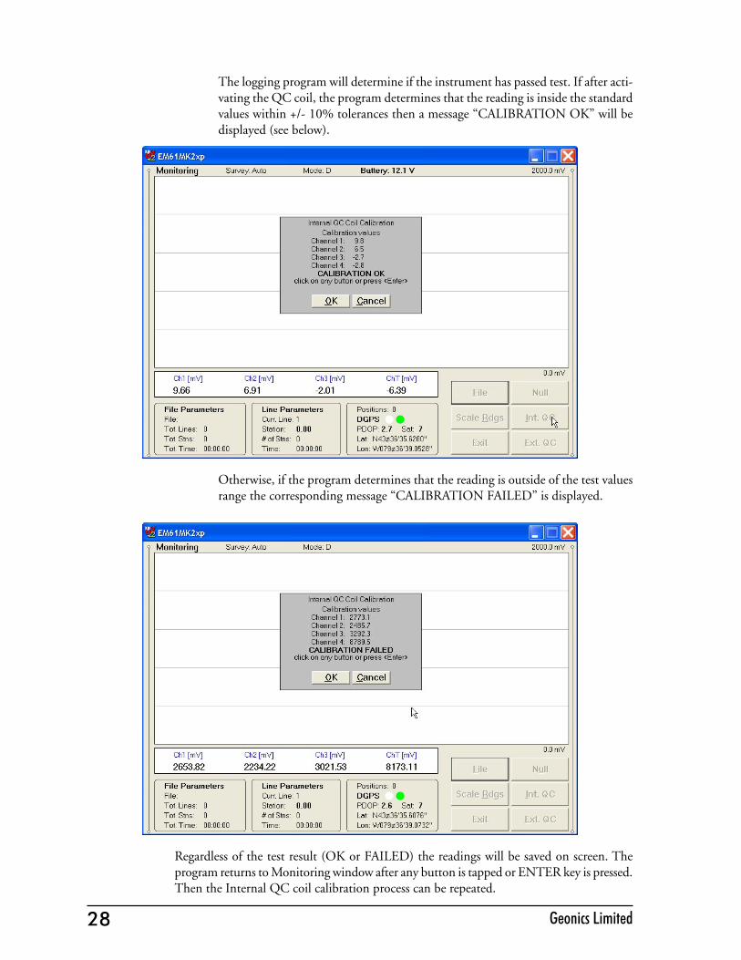
The logging program will determine if the instrument has passed test. If after acti-vating the QC coil, the program determines that the reading is inside the standard values within +/- 10% tolerances then a message “CALIBRATION OK” will be displayed (see below).
Otherwise, if the program determines that the reading is outside of the test values range the corresponding message “CALIBRATION FAILED” is displayed.
Regardless of the test result (OK or FAILED) the readings will be saved on screen. The program returns to Monitoring window after any button is tapped or ENTER key is pressed. Then the Internal QC coil calibration process can be repeated.
28 Geonics Limited 29EM61MK2 Data Logging System (DAS70-CX)
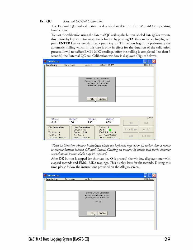
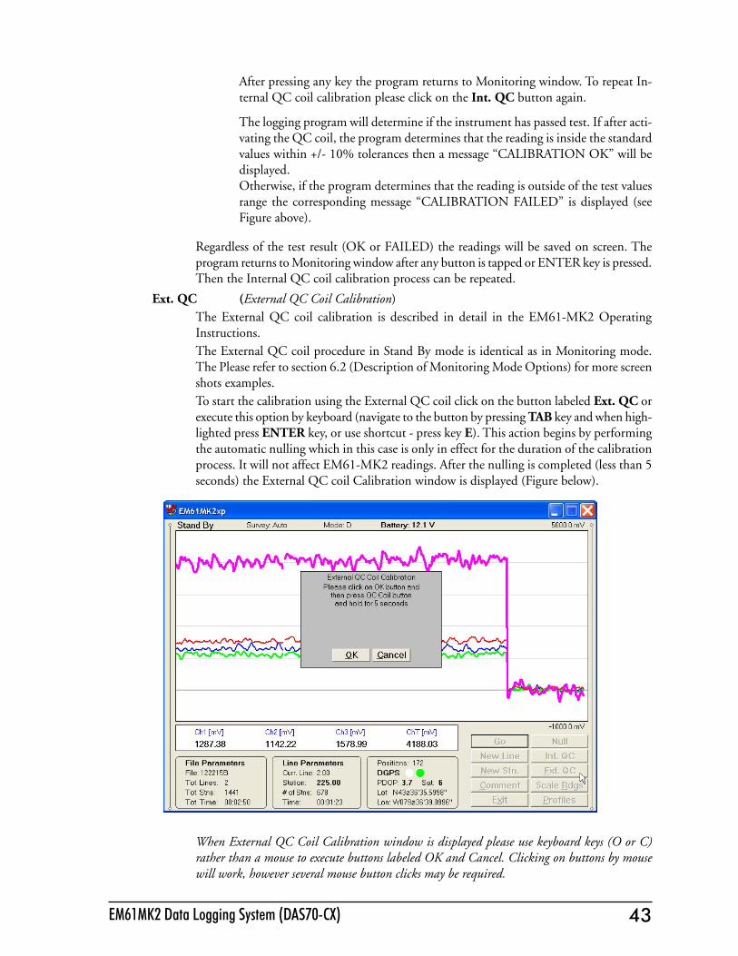
Ext. QC (External QC Coil Calibration)The External QC coil calibration is described in detail in the EM61-MK2 Operating Instructions.To start the calibration using the External QC coil tap the button labeled Ext. QC or execute this option by keyboard (navigate to the button by pressing TAB key and when highlighted press ENTER key, or use shortcut - press key E). This action begins by performing the automatic nulling which in this case is only in effect for the duration of the calibration process. It will not affect EM61-MK2 readings. After the nulling is completed (less than 5 seconds) the External QC coil Calibration window is displayed (Figure below).
When Calibration window is displayed please use keyboard keys (O or C) rather than a mouse to execute buttons labeled OK and Cancel. Clicking on buttons by mouse will work, however several mouse button clicks may be required.After OK button is tapped (or shortcut key O is pressed) the window displays timer with elapsed seconds and EM61-MK2 readings. This display lasts for 60 seconds. During this time please follow the instructions provided on the Allegro screen.
30 Geonics Limited 31EM61MK2 Data Logging System (DAS70-CX)
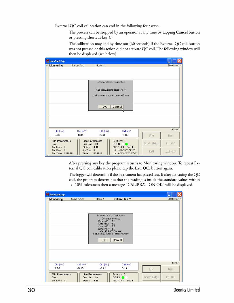
External QC coil calibration can end in the following four ways:
The process can be stopped by an operator at any time by tapping Cancel button or pressing shortcut key C.
The calibration may end by time out (60 seconds) if the External QC coil button was not pressed or this action did not activate QC coil. The following window will then be displayed (see below).
After pressing any key the program returns to Monitoring window. To repeat Ex-ternal QC coil calibration please tap the Ext. QC. button again.
The logger will determine if the instrument has passed test. If after activating the QC coil, the program determines that the reading is inside the standard values within +/- 10% tolerances then a message “CALIBRATION OK” will be displayed.

30 Geonics Limited 31EM61MK2 Data Logging System (DAS70-CX)
Otherwise, if the program determines that the reading is outside of the test values range the corresponding message “CALIBRATION FAILED” is displayed.
Regardless of the test result (OK or FAILED) the readings will be saved on screen. The program returns to Monitoring window after any button is clicked or ENTER key is pressed. Then the External QC coil calibration process can be repeated.
Scale (New Scale for Profile Plot)Selecting New Scale option allows the operator to enter new scale parameters for the profile plot. This option is available by clicking on the command button labeled Scale Rdgs. or directly from keyboard by using shortcut key <R>. The Readings Scale dialog will be displayed. It contains two text boxes for Minimum and

32 Geonics Limited 33EM61MK2 Data Logging System (DAS70-CX)
Maximum values of a new scale for profile plot. Current settings (minimum and maxi-mum values) for the scale are displayed in the bottom right and top right corners of the plot area.After minimum and maximum values are specified click on the button OK or press ENTER key to accept to accept new values and the profile plot area will be redrawn. To ignore an entry and return to Stand By mode click on the Cancel (X) button or press Esc key, the dialog window will disappear and measurements can be continued.
Exit (exit Monitor mode)After clicking on the Exit button (or executing this option using keyboard) the program immediately returns to Main Screen.
6.2 Stand By ModeAfter data file is created in Monitoring mode the program automatically switches logging window to Stand By mode. This windows is similar to Monitor mode however it contains survey parameters (file name, survey line name, etc.) and different set of options represented by buttons displayed at the bottom of the screen. The logging window in Stand By mode in initial state (before any data is recorded) is presented below.
The main portion of the screen is occupied by the plot area which displays profiles (see Figure below which shows Stand By mode after some data were collected). Readings in the plot area can be displayed in compressed amplitude scale, which corresponds to Square Root of the amplitude. In compressed amplitude scale 0 to 100 corresponds to 0 to 10,000 mV, and compressed range 0 to 200 corresponds to 0 to 40,000 mV. Plotting data in compressed amplitude allows you to show details in the low range of amplitude, as well as relatively good resolution in the high range of data on the small screen. Please note, that data displayed in the numeric form are always given in the standard, linear scale. The amplitude scale is divided by four or five grey grid lines. In the case where the amplitude scale starts with a negative value, then the grid line corresponding to zero is always plotted as a thicker line.
32 Geonics Limited 33EM61MK2 Data Logging System (DAS70-CX)
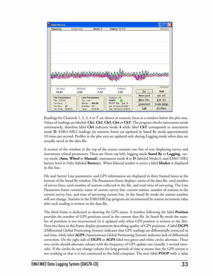
Readings for Channels 1, 2, 3, 4 or T are shown in numeric form in a window below the plot area. Values of readings are labeled: Ch1, Ch2, Ch3, Ch4 or ChT. The program checks instrument mode continuosely, therefore label Ch4 indicates mode 4 while label ChT corresponds to instrument mode D. EM61-MK2 readings (in numeric form) are updated in Stand By mode approximately 10 times per second. Profiles in the plot area are updated only during Logging mode when data are actually saved in the data file.
A section of the window at the top of the screen contains one line of text displaying survey and instrument related parameters. These are (from top left): logging mode Stand By or Logging, sur-vey mode (Auto, Wheel or Manual), instrument mode 4 or D (labeled Mode:)), and EM61-MK2 battery level in Volts (labeled Battery:). When fiducial marker is active a label Marker is displayed in this line.
File and Survey Line parameters, and GPS information are displayed in three framed boxes at the bottom of the Stand By window. File Parameters frame displays: name of the data file, total number of survey lines, total number of stations collected in the file, and total time of surveying. The Line Parameters frame contains: name of current survey line, current station, number of stations in the current survey line, and time of surveying current line. In the Stand By mode the station number will not change. Stations in the EM61MK2xp program are incremented by station increment value after each reading is written to the data file.
The third frame is dedicated to showing the GPS status. A number following the label Position provides the number of GPS positions saved in the current data file. In Stand By mode the num-ber of positions is not incremented (it is updated only when GPS position is written to the file). Next two lines in this frame display parameters describing quality of GPS positions. A label DGPS (Differential Global Positioning System) indicates that GPS readings are differentially corrected in real time, while label AGPS (Autonomous Global Positioning System) indicates lack of differential correction. On the right side of DGPS or AGPS label two green and white circles alternate. These two circles should alternate colours with the frequency of GPS update rate (usually 1 second inter-vals). If the circles do not change colours for long periods of time it means that the GPS system is not working or that it is not connected to the field computer. The next label PDOP with a value

34 Geonics Limited 35EM61MK2 Data Logging System (DAS70-CX)
varying between 0 and 99.9 represents an index called Position Dilution of Precision (PDOP). This value is available only when messages both, GGA and GSA are received from GPS. The last label Sat and following number shows the number of currently tracked satellites. Two bottom lines of the frame give current Latitude and Longitude of the instrument position (datum WGS1984). Position is updated with frequency of GPS receiver stream.
In case of any problems with instrument connection, battery failure, or accidental instrument Turn Off a message "No Communication, trying" will be displayed in numeric values window. The mes-sage is highlighted by red background to alert operator as fast as possible. The EM61MK2xp will try to re-establish communication and after the problem is corrected the program will start com-munication automaticaly. Alternatively, click on the Exit button or execute this command from a keyboard. The program window in Stand By mode and the alert message is shown below.
Several available field options (in form of command buttons) are listed at the bottom right corner of the Stand By mode window. They will be described in the following section 6.4.
6.3 Logging ModeThe Logging mode is enabled by clicking on the button labeled GO (log data) or pressing the shortcut key G (or the <ENTER> key if button GO is highlighted) in Stand By mode. After this button is pressed the list of buttons at bottom of the screen will be replaced by one PAUSE button, label Stand By will be replaced by label Logging (at the top of the display) and data will be logged in the mode corresponding to the selected EM61-MK2 mode in the Survey Setup menu. All labels and parameters (with the exception of buttons representing Stan By mode options) are the same as in Stand By mode and they are described in the preceding section 6.2. The screen in Logging mode is presented below.
After the screen changes to Logging mode the current station (labeled Station:) is updated according to the station interval. Similarly, if GPS Input was enabled, total number of GPS positions (label Positions) in the data file is incremented every time (usually once a second) GPS position is written

34 Geonics Limited 35EM61MK2 Data Logging System (DAS70-CX)
to the file. Profile curves (for channels selected in Display Options window) are updated after each reading is written to the data file.
In case of any problems with instrument connection, battery failure, or accidental instrument Turn Off a message "No Communication, trying" will be displayed in numeric values window. The mes-sage is highlighted by red background to alert operator as fast as possible. The EM61MK2xp will stop collecting data and will try to re-establish communication. After the problem is corrected the program will start communication automaticaly. Alternatively, click on the Pause button to return to Stand By mode. The program window in Stand By mode and the alert message is shown below.

36 Geonics Limited 37EM61MK2 Data Logging System (DAS70-CX)
There is only one option available in the Logging mode - pause logging. After a Pause button is clicked or Pause key (any key or other Pause Key selected in Logger Setup window) is pressed the recording is stopped and the Logging mode returns to the Stand By mode. In Stand By mode the EM61-MK2 data will be displayed with the update rate approximately 10 readings per second, however data will not be saved in the log file and profile curves will be not updated.
Exiting from the logging session and access to various field options are available only from the log-ging window in Stand By mode.
6.4 Stand By Mode Field OptionsSeveral field options are available while the Logging window is in the Stand By mode. Options can be accessed directly from command buttons. Command buttons can be used by clicking on the desired button, or from the keyboard by pressing one of the shortcut keys (underlined characters on button labels) or by navigating using <TAB> key (sets button as a default button - default button is highlighted) and pressing <ENTER> key.
GO (log data) (start data logging)Click on the GO button, or while using the keyboard press shortcut key <G> or if the button is a default button (highlighted) press <ENTER>. The logging window in Stand By mode will change to Logging mode and logging data starts immediately.
New Line (New Survey Line)The New Survey Line dialog is displayed (see Figure below). Selecting this option allows the operator to enter a new survey line number (name) and associated line parameters (Line Increment, Line Sequence, Direction, Start Station, and Station Increment). The new line number and associated parameters are prompted by the program based on parameters specified in the Survey Setup dialog.

36 Geonics Limited 37EM61MK2 Data Logging System (DAS70-CX)
At the top of the dialog the last survey line name and the last logged station are displayed. Default name for the new line is given based on the Line Increment parameter. The default Start Station, direction of the Station Increment, and Direction are determined based on Sequence selection. All these parameters can be overwritten by the user as described in the Survey Setup menu description (chapter 2).After all the parameters in the New Line dialog are updated click on the button OK or press ENTER key to accept the displayed settings. The program will return to the Logging window in Stand By mode. Survey line name (Curr. Line) name and current station (Sta-tion) value will be updated and profile curves plot for former survey line will disappear. To return to Stand By mode and current survey line settings (state before this dialog was selected) click on the Cancel (X) button or press Esc key.
New Stn. (New Station)Selecting this option allows the operator to enter a new station number (within the same survey line). The New Station dialog is displayed.
Current survey line, Start and Current station are displayed at the top of the dialog. The New Station can be entered in the provided edit box labeled New Station. Click on the button OK or press ENTER key to accept the new value. The program will return to the Logging window in Stand By mode. Current station (Station:) value will be updated and after data logging is activated the profile curves will have a small gap (two pixels) showing the new station entry (see Figure below). To return to Stand By mode and current survey line settings (state before this dialog was selected) click on the Cancel (X) button or press Esc key, the dialog window will disappear and measurements can be continued.
38 Geonics Limited 39EM61MK2 Data Logging System (DAS70-CX)
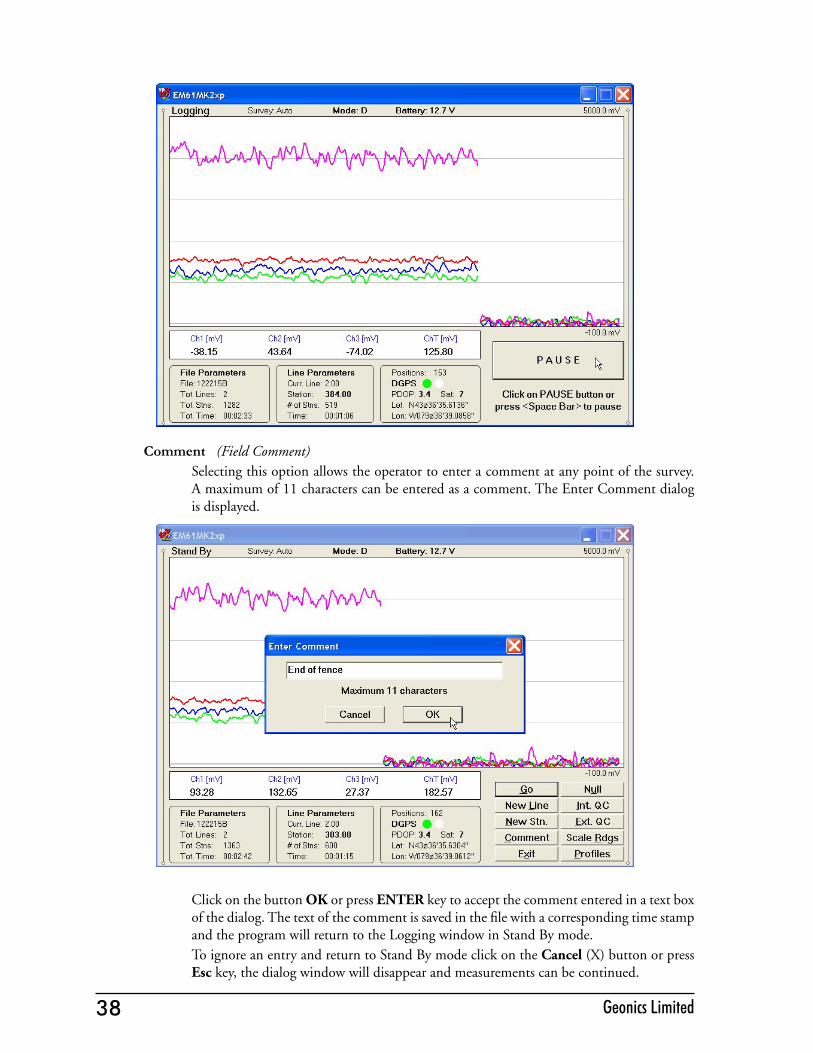
Comment (Field Comment)Selecting this option allows the operator to enter a comment at any point of the survey. A maximum of 11 characters can be entered as a comment. The Enter Comment dialog is displayed.
Click on the button OK or press ENTER key to accept the comment entered in a text box of the dialog. The text of the comment is saved in the file with a corresponding time stamp and the program will return to the Logging window in Stand By mode. To ignore an entry and return to Stand By mode click on the Cancel (X) button or press Esc key, the dialog window will disappear and measurements can be continued.

38 Geonics Limited 39EM61MK2 Data Logging System (DAS70-CX)
Scale Rdgs (New Scale for Profile Plot)Selecting New Scale option allows the operator to enter new scale parameters for the profile plot.
The Enter Scale dialog will be displayed. It contains two text boxes for Minimum and Maxi-mum values of a new scale for profile plot. Current settings (minimum and maximum values) for the scale are displayed in the bottom right and top right corners of the plot area.After minimum and maximum values are specified click on the button OK or press ENTER key to accept new values and the profile plot area will be redrawn (see Figure below).
To ignore an entry and return to Stand By mode tap the Cancel (X) button or press Esc key, the dialog window will disappear and measurements can be continued.

40 Geonics Limited 41EM61MK2 Data Logging System (DAS70-CX)
Profiles (new options for profile plot display)After the Profiles button was clicked or executed from the keyboard the Display Options dialog window appears on the screen. This dialog allows you to enable and disable the display of each channel profile, specify color and thickness of profiles, and select linear or compressed amplitude for profiles. The dialog is presented below.
Please refer to chapter 5 where this dialog and its parameters are described in detail.Click on the button OK or press ENTER key to accept updated display parameters. The dialog will disappear and profile plot area will be redrawn in Stand By mode. To return to Stand By mode and current display options (state before this dialog was selected) click on the Cancel (X) button or press Esc key, the dialog window will disappear.
NullDuring data collection (in Stand By mode) a confirmation message will be displayed (there is no such message if Nulling is performed in Monitoring mode) before actual operation is applied.

40 Geonics Limited 41EM61MK2 Data Logging System (DAS70-CX)
After above message is confirmed the program collects 50 readings and calculates the in-strument offset.
The calculated offset is applied to all the readings that follow this operation. If needed, this procedure can be repeated several times until satisfactory results are obtained. However, there is no associated “Undo” function. If original values (without calculated offsets) of the EM61-MK2 readings are needed, exit the EM61MK2 program and run it again. The EM61-MK2 instrument does not have to be turned OFF.
Int. QC (Internal QC coil calibration)The Internal QC coil calibration is described in detail in the EM61-MK2 Operating Instructions.The Internal QC coil procedure in Stand By mode is identical as in Monitoring mode. The Please refer to section 6.2 (Description of Monitoring Mode Options) for more screen shots examples.To start the calibration using Internal QC coil click on the key labeled Int. QC or execute this option by keyboard (navigate to the button by pressing TAB key and when highlighted press ENTER key, or use shortcut - press key I). This action begins by performing the auto-matic nulling which in this case is only in effect for the duration of the calibration process. It will not affect EM61-MK2 readings dueing later data collection. After the nulling is completed (less than 5 seconds) the Internal QC coil Calibration window is displayed. All command buttons in the bottom right corner of the logging window in Stand By mode are disabled during Calibration procedure.
When Calibration window is displayed please use keyboard keys (O or C) rather than a mouse to execute buttons labeled OK and Cancel. Clicking on buttons by mouse will work, however several mouse button clicks may be required.

42 Geonics Limited 43EM61MK2 Data Logging System (DAS70-CX)
After OK button is clicked (or shortcut key O is pressed) the window displays timer with elapsed seconds and EM61-MK2 readings. This display lasts for 60 seconds. During this time please follow the instructions provided on the Allegro screen.
Internal QC coil calibration can end in the following four ways:
The process can be stopped by an operator at any time by clicking on the Cancel button or pressing shortcut key C.
The calibration may end by time out (60 seconds) if QC coil button was not pressed or this action did not activate QC coil.
42 Geonics Limited 43EM61MK2 Data Logging System (DAS70-CX)
After pressing any key the program returns to Monitoring window. To repeat In-ternal QC coil calibration please click on the Int. QC button again.
The logging program will determine if the instrument has passed test. If after acti-vating the QC coil, the program determines that the reading is inside the standard values within +/- 10% tolerances then a message “CALIBRATION OK” will be displayed.Otherwise, if the program determines that the reading is outside of the test values range the corresponding message “CALIBRATION FAILED” is displayed (see Figure above).
Regardless of the test result (OK or FAILED) the readings will be saved on screen. The program returns to Monitoring window after any button is tapped or ENTER key is pressed. Then the Internal QC coil calibration process can be repeated.
Ext. QC (External QC Coil Calibration)The External QC coil calibration is described in detail in the EM61-MK2 Operating Instructions.The External QC coil procedure in Stand By mode is identical as in Monitoring mode. The Please refer to section 6.2 (Description of Monitoring Mode Options) for more screen shots examples.To start the calibration using the External QC coil click on the button labeled Ext. QC or execute this option by keyboard (navigate to the button by pressing TAB key and when high-lighted press ENTER key, or use shortcut - press key E). This action begins by performing the automatic nulling which in this case is only in effect for the duration of the calibration process. It will not affect EM61-MK2 readings. After the nulling is completed (less than 5 seconds) the External QC coil Calibration window is displayed (Figure below).
When External QC Coil Calibration window is displayed please use keyboard keys (O or C) rather than a mouse to execute buttons labeled OK and Cancel. Clicking on buttons by mouse will work, however several mouse button clicks may be required.

44 Geonics Limited
After OK button is tapped (or shortcut key O is pressed) the window displays timer with elapsed seconds and EM61-MK2 readings. This display lasts for 60 seconds. During this time please follow the instructions provided on the Allegro screen.
External QC coil calibration can end in the following four ways:
The process can be stopped by an operator at any time by tapping Cancel button or pressing shortcut key C.
The calibration may end by time out (60 seconds) if the External QC coil button was not pressed or this action did not activate QC coil.
After pressing any key the program returns to Monitoring window. To repeat Ex-ternal QC coil calibration please tap the Ext. QC. button again.
The logger will determine if the instrument has passed test. If after activating the QC coil, the program determines that the reading is inside the standard values within +/- 10% tolerances then a message “CALIBRATION OK” will be displayed.Otherwise, if the program determines that the reading is outside of the test values range the corresponding message “CALIBRATION FAILED” is displayed.
Regardless of the test result (OK or FAILED) the readings will be saved on screen. The program returns to Monitoring window after any button is clicked or ENTER key is pressed. Then the External QC coil calibration process can be repeated.
Exit (exit data logging)During data collection (in Stand By mode) a confirmation message will be displayed (there is no such message if Exit is performed in Monitoring mode) before program exits logging window.
After above message is confirmed the program stops logging, closes data file and returns to Main Screen.
45EM61MK2xp Data Logging System (DAS70-XP)
Appendix A
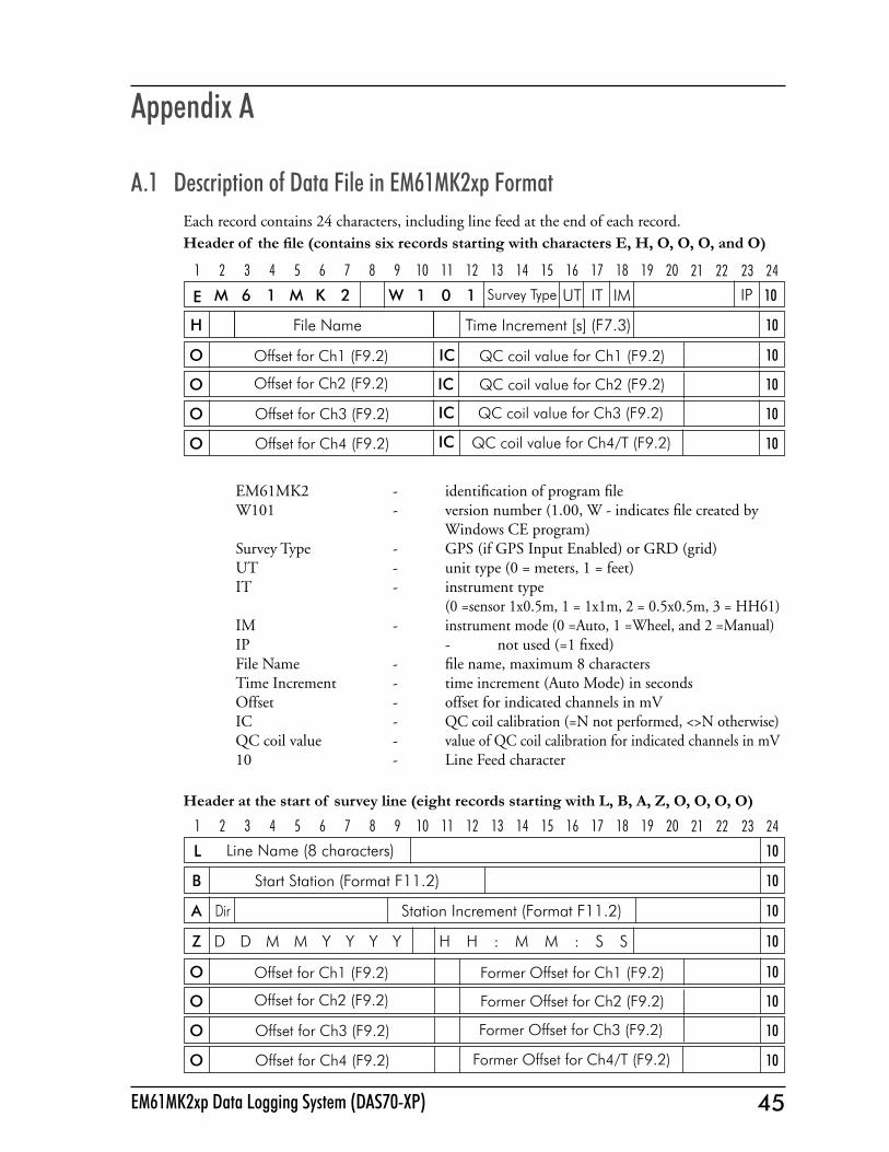
A.1 Description of Data File in EM61MK2xp FormatEach record contains 24 characters, including line feed at the end of each record.Header of the file (contains six records starting with characters E, H, O, O, O, and O)
EM61MK2 - identification of program fileW101 - version number (1.00, W - indicates file created by Windows CE program)Survey Type - GPS (if GPS Input Enabled) or GRD (grid)UT - unit type (0 = meters, 1 = feet) IT - instrument type (0 =sensor 1x0.5m, 1 = 1x1m, 2 = 0.5x0.5m, 3 = HH61)IM - instrument mode (0 =Auto, 1 =Wheel, and 2 =Manual)IP - not used (=1 fixed)File Name - file name, maximum 8 charactersTime Increment - time increment (Auto Mode) in secondsOffset - offset for indicated channels in mVIC - QC coil calibration (=N not performed, <>N otherwise)QC coil value - value of QC coil calibration for indicated channels in mV10 - Line Feed character
Header at the start of survey line (eight records starting with L, B, A, Z, O, O, O, O)
1 2 3 4 5 6 7 8 9 10 11 12 13 14 15 16 17 18 19 20 21
10
22
L
O Offset for Ch1 (F9.2) 10
O Offset for Ch3 (F9.2) 10
O Offset for Ch2 (F9.2) 10
O Offset for Ch4 (F9.2) 10
B Start Station (Format F11.2) 10
23 24
Former Offset for Ch1 (F9.2)
Former Offset for Ch2 (F9.2)
Former Offset for Ch3 (F9.2)
Former Offset for Ch4/T (F9.2)
A Dir Station Increment (Format F11.2) 10
Z D D M M Y Y Y Y H H : M M : S S 10
Line Name (8 characters)
1 2 3 4 5 6 7 8 9 10 11 12 13 14 15 16 17 18 19 20 21
M 6 1 W 1 0 UT1 IT IM 10
22
E Survey Type
O Offset for Ch1 (F9.2) 10
O Offset for Ch3 (F9.2) 10
O Offset for Ch2 (F9.2) 10
O Offset for Ch4 (F9.2) 10
H File Name Time Increment [s] (F7.3) 10
M K 2
23 24
IC
IC
IC
IC
QC coil value for Ch1 (F9.2)
QC coil value for Ch2 (F9.2)
QC coil value for Ch3 (F9.2)
QC coil value for Ch4/T (F9.2)
IP

46 Geonics Limited 47EM61MK2xp Data Logging System (DAS70-XP)
Line Name - Line Name, maximum 8 charactersStart Station - Start Station for the Line, format F11.2Dir - Direction of the Line (E, W, N, or S)Station Inc. - Station Increment, format F11.3Date - Date when Line was created, format DD-MM-YYYYTime - Real Time when Line was created, format HH:MM:SSOffset - Offset for indicated channels in mV at the start of LineFormer Offset - Former offset for indicated channels in mV10 - Line Feed character
Timer Relation
Indicates relation between computer clock and the program timer. This record links timer in milliseconds and computer time (local time) in format HH:MM:SS.sss. This record is written to the file each time a new new line is entered.
Reading
I - indicator T, D, E, F, M, N, P, or Q. Each record representing reading starts with one of the following character, which indicates type of reading: T - Standard, Mode 4, channels 1, 2, 3, 4 D - Standard, Mode D, channels 1, 2, 3, T E - Hand Held, Mode 4, channels 1, 2, 3, 4 F - Hand Held, Mode D, channels 1, 2, 3, T M - Standard, Mode 4, channels 1, 2, 3, 4 +Marker N - Standard, Mode D, channels 1, 2, 3, T +Marker P - Hand Held, Mode 4, channels 1, 2, 3, 4 +Marker Q - Hand Held, Mode D, channels 1, 2, 3, T +MarkerGn - one character parameter (Hex format), contains Gain, see table of ranges at the end of this section.1h - higher byte of the 2’s complement Hex number of Channel 11l - lower byte of Channel 12h - higher byte of the 2’s complement Hex number of Channel 22l - lower byte of Channel 23h - higher byte of the 2’s complement Hex number of Channel 33l - lower byte of Channel 34h - higher byte of the 2’s complement Hex number of Channel 44l - lower byte of Channel 45h - higher byte of the 2’s complement Hex number of TX current5l - lower byte of TX current6 - fraction of current (5h 5l), Hex numberTime Stamp - time in ms from the Windows start (resets every 49.7 days)10 - Line Feed character
* Computer Time (Format HH:MM:SS.sss) 10Time Stamp in milliseconds1 2 3 4 5 6 7 8 9 10 11 12 13 14 15 16 17 18 19 20 21 22 23 24
I Gn 3l3h2l2h 4h 5h 5l 6 Time Stamp in ms (10 digits)4l 101h 1l
1 2 3 4 5 6 7 8 9 10 11 12 13 14 15 16 17 18 19 20 21 22 23 24
46 Geonics Limited 47EM61MK2xp Data Logging System (DAS70-XP)
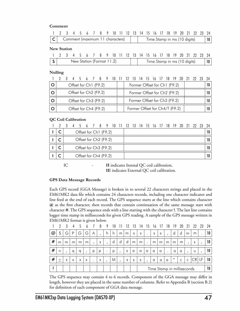
Comment
New Station
Nulling
QC Coil Calibration
IC - II indicates Inrenal QC coil calibration, IE indicates External QC coil calibration.
GPS Data Message Records
Each GPS record (GGA Message) is broken in to several 22 characters strings and placed in the EM61MK2 data file which contains 24 characters records, including one character indicator and line feed at the end of each record. The GPS sequence starts at the line which contains character @ as the first character, then records that contain continuation of the same message start with character #. The GPS sequence ends with a line starting with the character !. The last line contains logger time stamp in milliseconds for given GPS reading. A sample of the GPS message written in EM61MK2 format is given below.
The GPS sequence may contain 4 to 6 records. Component of the GGA message may differ in length, however they are placed in the same number of columns. Refer to Appendix B (section B.2) for definition of each component of GGA data message.
C Comment (maximum 11 characters) 10Time Stamp in ms (10 digits)1 2 3 4 5 6 7 8 9 10 11 12 13 14 15 16 17 18 19 20 21 22 23 24
S New Station (Format 11.2) 10Time Stamp in ms (10 digits)1 2 3 4 5 6 7 8 9 10 11 12 13 14 15 16 17 18 19 20 21 22 23 24
O Offset for Ch1 (F9.2) 10
O Offset for Ch3 (F9.2) 10
O Offset for Ch2 (F9.2) 10
O Offset for Ch4 (F9.2) 10
Former Offset for Ch1 (F9.2)
Former Offset for Ch2 (F9.2)
Former Offset for Ch3 (F9.2)
Former Offset for Ch4/T (F9.2)
1 2 3 4 5 6 7 8 9 10 11 12 13 14 15 16 17 18 19 20 21 22 23 24
I Offset for Ch1 (F9.2) 10
I Offset for Ch3 (F9.2) 10
I Offset for Ch2 (F9.2) 10
I Offset for Ch4 (F9.2) 10
1 2 3 4 5 6 7 8 9 10 11 12 13 14 15 16 17 18 19 20 21 22 23 24C
C
C
C
1 2 3 4 5 6 7 8 9 10 11 12 13 14 15 16 17 18 19 20 21 22
@ $ ,AGG h m m s s . s s ,h d d m 10G P
#
m
mmmm , , d d d m m . ms m m m 10
.
m
#
m
q,n
,
q p p . p , s a a, a a a 10
, s
#
.
+
,u,
x x x . x , M , sx s s , 10
a a
!
a CRcc* LF
10
a a
Time Stamp in milliseconds
23 24

48 Geonics Limited 49EM61MK2xp Data Logging System (DAS70-XP)
A.2 Conversion FactorsEM61MK2 has four channels. Channels 1, 2, and 3 are common for Mode 4 and Mode D. Chan-nel 4 in Mode D is named Channel T (it corresponds to Top coil).
The instrument response is converted to output voltage in mV for each sampling channel as given below. Channel 1 to 4 - converted data DATA1 (to 4) - instrument output for each channel as recorded in logger RANGE - range is controlled by the EM61MK2, it can be 1, 10, 100
Standard Unit - Mode 4 (One Sensor 1 x 0.5 m or 1 x 1 m)Channel 1=(DATA1 x 4.8333 x 2)/RANGEChannel 2=(DATA2 x 4.8333 x 2)/RANGEChannel 3=(DATA3 x 4.8333 x 2)/RANGEChannel 4=(DATA4 x 4.8333 x 2)/RANGE
Standard Unit - Mode D (Two Sensors 1 x 0.5 m or 1 x 1 m, Top and Bottom coils))Channel 1=(DATA1 x 4.8333 x 2)/RANGEChannel 2=(DATA2 x 4.8333 x 2)/RANGEChannel 3=(DATA3 x 4.8333 x 2)/RANGEChannel T=(DATA4 x 4.8333 x 4)/RANGE
if coil is 1 x 0.5 m Channel T is further multiplied by a factor 1.114.
Hand Held Unit - Mode 4 (One Sensor) Channel 1 = 0.902500 x (DATA1 x 4.8333)/RANGE Channel 2 = 1.363000 x (DATA2 x 4.8333)/RANGE Channel 3 = 2.026795 x (DATA3 x 4.8333)/RANGE Channel 4 = 3.018856 x (DATA4 x 4.8333)/RANGE
Hand Held Unit - Mode D (Two Sensors, Top and Bottom coils)) Channel 1 = 0.9025 x (DATA1 x 4.8333)/RANGE Channel 2 = 1.3630 x (DATA2 x 4.8333)/RANGE Channel 3 = 2.0430 x (DATA3 x 4.8333)/RANGE Channel T = 12.152 x (DATA4 x 4.8333)/RANGE
Further each channel is normalized by current following formula:
Standard UnitChannel = Channel x 3000/Current
Hand Held UnitChannel = Channel x 1800/Current
where, current is a value represented by 5h, 5l, and 6 in EM61MK2 data file (see section B.1)

48 Geonics Limited 49EM61MK2xp Data Logging System (DAS70-XP)
HEX Ch1 Ch2 Ch3 Ch4
C0 100 1 1 1C1 100 1 1 10C3 100 1 1 100C4 100 1 10 1C5 100 1 10 10C7 100 1 10 100CC 100 1 100 1CD 100 1 100 10CF 100 1 100 100D0 100 10 1 1D1 100 10 1 10D3 100 10 1 100D4 100 10 10 1D5 100 10 10 10D7 100 10 10 100DC 100 10 100 1DD 100 10 100 10DF 100 10 100 100F0 100 100 1 1F1 100 100 1 10F3 100 100 1 100F4 100 100 10 1F5 100 100 10 10F7 100 100 10 100FC 100 100 100 1FD 100 100 100 10FF 100 100 100 100
HEX Ch1 Ch2 Ch3 Ch4
40 10 1 1 141 10 1 1 1043 10 1 1 10044 10 1 10 145 10 1 10 1047 10 1 10 1004C 10 1 100 14D 10 1 100 104F 10 1 100 10050 10 10 1 151 10 10 1 1053 10 10 1 10054 10 10 10 155 10 10 10 1057 10 10 10 1005C 10 10 100 15D 10 10 100 105F 10 10 100 10070 10 100 1 171 10 100 1 1073 10 100 1 10074 10 100 10 175 10 100 10 1077 10 100 10 1007C 10 100 100 17D 10 100 100 107F 10 100 100 100
HEX Ch1 Ch2 Ch3 Ch4
0 1 1 1 1 1 1 1 1 10 3 1 1 1 100 4 1 1 10 1 5 1 1 10 10 7 1 1 10 100 C 1 1 100 1 D 1 1 100 10 F 1 1 100 10010 1 10 1 111 1 10 1 1013 1 10 1 10014 1 10 10 115 1 10 10 1017 1 10 10 1001C 1 10 100 11D 1 10 100 101F 1 10 100 10030 1 100 1 131 1 100 1 1033 1 100 1 10034 1 100 10 135 1 100 10 1037 1 100 10 1003C 1 100 100 13D 1 100 100 103F 1 100 100 100
Table of Ranges Determined by the EM61-MK2 Microprocessor

50 Geonics Limited
A.3 Example of Data File in EM61MK2xp FormatThe Em61MK2 data file records are written in binary format, therefore the file may have different shape when displayed or printed, depending on particular video or pronter settings.
EM61MK2 W100GPS000 1 H 042320A 0.200 O 0.00E 0.00 O 0.00E 0.00 O 0.00E 0.00 O 0.00E 0.00 L0 B 0.00 AS 1.000 Z23042005 20:02:51 O 0.00 0.00 O 0.00 0.00 O 0.00 0.00 O 0.00 0.00 *20:02:51.000 4179829@$GPGGA,020412.00,4336.#59410,N,07936.64856,W,#2,6,2,141.56,M,-35,M,5#,119*55 ! 4287423@$GPGSA,A,3,30,,,25,,20#,,14,,06,,01,02.8,02.1#,02.0*0D ! 4287441Eÿ Ø `/^ ”N 4287673Eÿ †/“ ”Q 4287879C comment text 4287983Eÿ ; G/yï ”O 4288089Eÿ § h/1⁄4þ ”W 4288279@$GPGGA,020413.00,4336.#59408,N,07936.64857,W,#2,6,2,141.51,M,-35,M,6#,119*58 ! 4288338Eÿ ¶ 5/ # ”S 4288488@$GPGSA,A,3,30,,,25,,20#,,14,,06,,01,02.8,02.1#,02.0*0D ! 4288419Eÿ þ º/j ”O 4288677Eÿ L t/k ”Q 4288885@$GPGGA,020414.00,4336.#59411,N,07936.64846,W,#2,6,2,141.68,M,-35,M,6#,119*5D ! 4289337Eÿ 4 (/± • 4290288@$GPGGA,020415.00,4336.#59411,N,07936.64845,W,#2,6,2,141.69,M,-35,M,7#,119*5F ! 4290338Eÿ È 1/Y • 4290496@$GPGSA,A,3,30,,,25,,20#,,14,,06,,01,02.8,02.1#,02.0*0D ! 4290417Eÿtr /F 4290687Eÿkø/ à • 4290893Eÿh/là • 4291101Eÿ2 Å/5Ñ • 4291293@$GPGGA,020416.00,4336.#59420,N,07936.64848,W,#2,6,2,142.11,M,-35,M,4#,119*5C ! 4291335EtsÝ3 • 4291502@$GPGSA,A,3,30,,,25,,20#,,14,,06,,01,02.8,02.1#,02.0*0D ! 4291414Eÿ*‚ b Œ ”Y 4291691C building 4291793E# *â ”V 4291900E¸/D ”C 4292299
51EM61MK2xp Data Logging System (DAS70-XP)
Appendix B
B.1 Using the EM61MK2xp with a GPS ReceiverThe EM61MK2xp program accepts input from GPS receiver that stream NMEA-0183 compatible data through their output port. The program uses two NMEA messages: GGA and GSA. The entire GGA message is used later by the DAT61MK2 program, while the GSA message is used only to display PDOP index on the logger screen.
The GPS system means (control device, receiver panel, or manufacturer software) must be used to set GPS receiver communication parameters, to specify frequency of GPS output, and number and type of NMEA messages sent by the GPS system output port. Any GPS system can send various NMEA messages. It is important to select only two messages (GGA and GSA) that are actually used by EM61MK2. The program will accept any GPS string sent by the GPS receiver, however it uses time to process GPS data that is not being used. Therefore, selecting a larger number of NMEA messages for GPS output will result in slower data acquisition of EM61MK2xp. Normally, the EM61MK2xp running in a Windows XP based computer uses less than 100 ms to process and record GPS data from two NMEA messages, GGA and GSA.
Only message GGA is necessary to position EM61-MK2 data. If message GSA is not available in a particular system, the EM61MK2xp will function and record position data based on GGA message. Lack of GSA message will result in PDOP index displayed as Not Available (N/A) on the logger display. Using message GGA alone will also result in slightly faster operation of the program. The speed can be further improved by setting higher Baud Rate (if it is supported by the employed GPS receiver) in Set GPS Port menu.
The EM61MK2xp dedicates portion of the display and shows GPS status in a frame box. A number following the label Position provides the number of GPS positions saved in the current data file. Next two lines in this frame display parameters describing quality of GPS positions. A label DGPS (Differential Global Positioning System) indicates that GPS readings are differentially corrected in real time, while label AGPS (Autonomous Global Positioning System) indicates lack of differential correction. On the right side of DGPS or AGPS label two green and white circles alternate. These two circles should alternate colours with the frequency of GPS update rate (usually 1 second inter-vals). If the circles do not change colours for long periods of time it means that the GPS system is not working or that it is not connected to the field computer. The next label PDOP with a value varying between 0 and 99.9 represents an index called Position Dilution of Precision (PDOP). This value is available only when messages both, GGA and GSA are received from GPS. This index measures the strength of satellite coverage for a given area. PDOP is affected by the number of satellites visible and their relative positions in the sky. The smaller the number of PDOP the stronger the satellite coverage is. When there are more than 5 satellites widely spaced visible, the PDOP is 4 or less. However, when there are less satellites visible, or they are unevenly spaced in the sky, PDOP values can be 6 or higher. In most cases, the PDOP in an open sky is less than 3, and most accuracies given for many GPS systems are given for this norm. Refer to GPS documentation and literature for more information related to error sources of GPS positioning.The last label Sat and following number shows number of currently tracked satellites.
Two bottom lines of the frame give current Latitude and Longitude of the instrument position (datum WGS1984). Position is updated with frequency of GPS receiver stream.
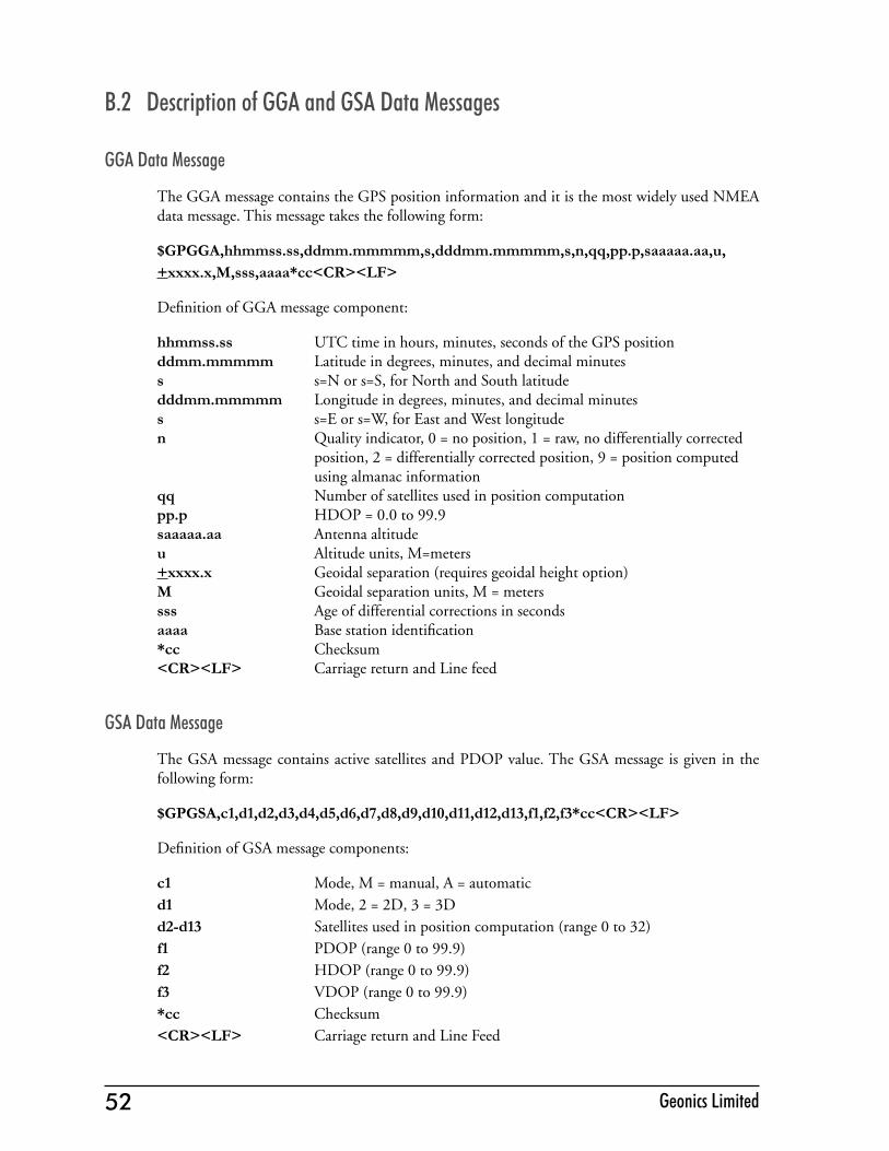
52 Geonics Limited
B.2 Description of GGA and GSA Data Messages
GGA Data Message
The GGA message contains the GPS position information and it is the most widely used NMEA data message. This message takes the following form:
$GPGGA,hhmmss.ss,ddmm.mmmmm,s,dddmm.mmmmm,s,n,qq,pp.p,saaaaa.aa,u,+xxxx.x,M,sss,aaaa*cc<CR><LF>
Definition of GGA message component:
hhmmss.ss UTC time in hours, minutes, seconds of the GPS positionddmm.mmmmm Latitude in degrees, minutes, and decimal minutess s=N or s=S, for North and South latitudedddmm.mmmmm Longitude in degrees, minutes, and decimal minutess s=E or s=W, for East and West longituden Quality indicator, 0 = no position, 1 = raw, no differentially corrected position, 2 = differentially corrected position, 9 = position computed using almanac informationqq Number of satellites used in position computationpp.p HDOP = 0.0 to 99.9saaaaa.aa Antenna altitudeu Altitude units, M=meters +xxxx.x Geoidal separation (requires geoidal height option)M Geoidal separation units, M = meterssss Age of differential corrections in secondsaaaa Base station identification*cc Checksum<CR><LF> Carriage return and Line feed
GSA Data Message
The GSA message contains active satellites and PDOP value. The GSA message is given in the following form:
$GPGSA,c1,d1,d2,d3,d4,d5,d6,d7,d8,d9,d10,d11,d12,d13,f1,f2,f3*cc<CR><LF>
Definition of GSA message components:
c1 Mode, M = manual, A = automaticd1 Mode, 2 = 2D, 3 = 3Dd2-d13 Satellites used in position computation (range 0 to 32)f1 PDOP (range 0 to 99.9)f2 HDOP (range 0 to 99.9)f3 VDOP (range 0 to 99.9)*cc Checksum<CR><LF> Carriage return and Line Feed