OPERATING INSTRUCTIONS - APAR
22
APAR - BIURO HANDLOWE 05-090 Raszyn, ul Galczyńskiego 6 Tel. (22) 853-48-56, 853-49-30, 101-27-31 E-mail: [email protected] Internet: www.apar.pl OPERATING INSTRUCTIONS AR247 HUMIDITY AND TEMPERATURE CONTROLLER Version 3.0.2 2019.02.22
Transcript of OPERATING INSTRUCTIONS - APAR

APAR - BIURO HANDLOWE 05-090 Raszyn, ul Gałczyńskiego 6 Tel. (22) 853-48-56, 853-49-30, 101-27-31 E-mail: [email protected] Internet: www.apar.pl
OPERATING INSTRUCTIONS
AR247
HUMIDITY AND TEMPERATURE
CONTROLLER
Version 3.0.2
2019.02.22

2
Thank you for choosing our product.
This manual will help you use your controller correctly, safely and to its full potential.
Read this manual carefully before installing and putting your controller to use.
In case of additional questions, please contact the technical advisor.
CONTENTS
1. SAFETY PRINCIPLES..................................................................................................................................... 3
2. INSTALLATION GUIDELINES....................................................................................................................... 3
3. GENERAL CHARACTERISTICS OF THE CONTROLLER ............................................................................. 3
4. CONTENTS OF THE SET ............................................................................................................................... 4
5. TECHNICAL DATA......................................................................................................................................... 4
6. DIMENSIONS OF THE DEVICE AND INSTALLATION DATA .................................................................... 5
7. DESCRIPTION OF TERMINAL STRIPS AND ELECTRICAL CONNECTIONS ............................................ 6
8. IMPORTANT COMMENTS PERTAINING TO OPERATION – using the suppression systems ............ 7
9. FUNCTIONS OF BUTTONS AND LED INDICATORS ................................................................................. 7
9.1. FUNCTION BUTTON AND BINARY INPUT ...................................................................................... 8
10. SETTING OF THE CONFIGURATION PARAMETERS .............................................................................. 9
11. QUICK ACCESS MENU ............................................................................................................................. 13
12. OUTPUT OPERATION CONFIGURATION ............................................................................................. 13
12.1. CHANGING THE PRESET OUTPUT VALUES ................................................................................. 13
12.2. TYPES OF OUTPUT CHARACTERISTICS ....................................................................................... 13
12.3. ANALOG OUTPUT ........................................................................................................................... 14
12.4. PID REGULATION ............................................................................................................................ 15
12.5. AUTOMATIC PID PARAMETER SELECTION ................................................................................. 15
12.6. PID PARAMETER CORRECTION .................................................................................................... 17
12.7. MANUAL AND REMOTE CONTROL FUNCTION ......................................................................... 17
13. MESSAGE AND ERROR SIGNALING ...................................................................................................... 17
14. CONNECTING THE CONTROLLER TO A COMPUTER AND AVAILABLE SOFTWARE....................... 18
15. RS485 COMMUNICATION INTERFACE (acc. to EIA RS-485) ............................................................. 18
16. MODBUS–RTU SERIAL TRANSMISSION PROTOCOL (SLAVE) .......................................................... 19
17. NOTES ........................................................................................................................................................ 21
Please pay particular attention to fragments marked with this sign.
The manufacturer reserves its rights to modify the design and software of the device without deteriorating its technical parameters.
!
3
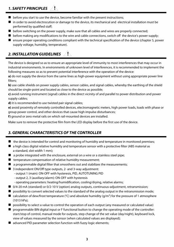
1. SAFETY PRINCIPLES
before you start to use the device, become familiar with the present instructions;
in order to avoid electrocution or damage to the device, its mechanical and electrical installation must be
performed by qualified staff;
before switching on the power supply, make sure that all cables and wires are properly connected;
before making any modifications to the wire and cable connections, switch off the device's power supply;
ensure proper operating conditions compliant with the technical specification of the device (chapter 5, power
supply voltage, humidity, temperature).
2. INSTALLATION GUIDELINES
The device is designed so as to ensure an appropriate level of immunity to most interferences that may occur in
industrial environments. In environments of unknown level of interferences, it is recommended to implement the
following measures so as to prevent potential interference with the operation of the device:
a) do not supply the device from the same lines as high-power equipment without using appropriate power line
filters;
b) use cable shields on power supply cables, sensor cables, and signal cables, whereby the earthing of the shield
should be single-point and located as close to the device as possible;
c) avoid running instrument (signal) cables in the direct vicinity of and parallel to power distribution and power
supply cables;
d) it is recommended to use twisted pair signal cables;
e) avoid proximity of remotely controlled devices, electromagnetic meters, high power loads, loads with phase or
group power control, and other devices that cause high impulse disturbances;
f) ground or zero metal rails on which rail-mounted devices are installed.
Make sure to remove the protective film from the LED display before the first use of the device.
3. GENERAL CHARACTERISTICS OF THE CONTROLLER
the device is intended for control and monitoring of humidity and temperature in monitored premises;
a high class digital relative humidity and temperature sensor with a protective filter (ABS material as
a standard, slot width 1 mm);
a probe integrated with the enclosure, external on a wire or a stainless steel pipe;
temperature compensation of relative humidity measurement;
a programmable digital filter that smoothens out and stabilizes the measurements;
3 independent ON/Off type outputs, 2- and 3-way adjustment:
- output 1 (main): ON-OFF with hysteresis, PID, AUTOTUNING PID
- output 2, 3 (auxiliary/alarm): ON-OFF with hysteresis
- operating parameters: heating/humidification, cooling/drying, relative alarms;
0/4-20 mA (standard) or 0/2-10 V (option) analog outputs, continuous-adjustment, retransmission;
possibility to convert selected values to the standard of the analog output in the retransmission mode;
calculation of dew/frost temperature (°C) and absolute humidity (g/m3) for the pressure of 1 atmosphere
(1013 hPa);
possibility to select a value to control the operation of each output (any measured or calculated value)
programmable BIN digital input or F functional button to change the operating mode of the controller:
start/stop of control, manual mode for outputs, step change of the set value (day/night), keyboard lock,
view of values measured by the sensor (when calculated values are displayed);
advanced PID parameter selection function with fuzzy logic elements;
!
!
4
manual mode (open control loop) available for binary outputs and the analog output, which makes it possible
to set the value of the output signal in the range of 0-100%; possibility of self-activation in the event of sensor
failure;
a two-line LED digital readout with brightness adjustment: UPPER display - humidity (%RH or g/m3), LOWER
display - temperature (of the sensor or the dew/frost point, °C ) or the value set for output 1
RS485 serial interface (galvanically isolated, MODBUS-RTU protocol, SLAVE);
programmable values to be displayed (measured or calculated values), adjustment, alarms, communication,
access, calibration options and other configuration parameters;
access to configuration parameters protected with a user password or not protected with a password
parameter configuration methods:
- from the film keypad located on the front panel of the device;
- through the RS485 or the AR956 (AR955) programmer and the ARSOFT-CFG WZ1 software
(Windows Vista/7/8/10) or a user's application, communication protocol MODBUS-RTU;
software and the AR956 (or AR955) programmer that enables viewing the measured value and quick
configuration of single or ready sets of parameters that were saved earlier on the computer for future use,
e.g. in other controllers of the same type (copying of configuration);
protection rating IP65 provided by the industrial enclosure which improves reliability of operation thanks
to high resistance to penetration of water and dusts and surface condensation of steam inside of the device;
options (to be selected at the time of ordering): type of measuring probe, 24 V AC/DC power supply,
SSR control outputs, 0/2-10 V analog output, and RS485 interface;
high accuracy, long-term stability, and immunity to interferences;
universal power supply 15-350 Vdc, 20-250 Vac / 50-60Hz
available accessories:
- AR956 or AR955 programmer;
- RS485/USB converter.
- a filter with a metal mesh that improves protection of the sensor against dust, mesh size 20-25 μm
- measurement probes: AR281, AR282 (on a wire), AR283 (box type), AR284/L150/L250 (steel tube)
NOTE:
Before you start working with the controller, make sure to become familiar with this operating instruction
and perform proper electrical and mechanical installation, as well as configuration of the parameters.
4. CONTENTS OF THE SET
controller, operating instructions, a warranty card.
5. TECHNICAL DATA
Measurement range for the probe 0÷100 %RH, -30÷80 °C,
do not pour water on the measuring probe
Sensor cover (ABS material, stainless steel mesh) mesh width: 0.15 mm, width of slots covers ABS: 1mm
diameter of ABS cover: 15mm, length of ABS cover: 40mm
Measurement accuracy (same as
for the SHT31 sensor made by
Sensirion)
- humidity typically ± 2% RH over the measuring range transmitter
- temperature typically ±0,3 °C over the measuring range transmitter
Additional errors - hysteresis ±0,8 %RH for temperature 25 °C
- long-term stability <0.25 %RH/year (1)
Measurement period and filtration 1s, delay of programmable digital filter: 0-5 s
Response time (63%) to step change of the
measured value
8s for air flow > 3,6km/h and switched off program filtration
!

5
Readout measurement resolution programmable: 0.1 or 1 %RH, °C , g/m3
Communication
interfaces
(RS485 and PRG, do
not use
simultaneously)
- RS485 (galvanically
separated), option
- baud rates 2.4-57.6 kb/s,
- character format 8N1 (8 data bits, 1 stop bit, no
parity bits)
- MODBUS-RTU protocol (SLAVE) - PRG programming
connection (no separation),
standard
Bistable outputs
(3 relays or SSR type)
- relays (P1-P3), standard 1 main (SPDT), 8A / 250 VAC (for resistance loads),
2 additional (SPST-NO), 5A / 250 VAC
- SSR (SSR1-SSR3), option transistor type NPN OC, 11 V, internal resistance 440 Ω,
Analog output
(1 current [mA] or
voltage [V] output)
- 0/4-20 mA (standard) resolution 12 bit, output load capacity Ro < 500 Ω
- 0/2-10 V (option) resolution 12 bit, output load capacity Io < 4 mA (Ro > 2,5 kΩ)
- output error basic < 0.1% ±0.01%/°C of the starting range
Binary input BIN (bistable) contact or voltage < 24 V, active when: short circuit or <0.8 V
A 7-segment LED display
(2 lines 3 digits each, with brightness
adjustment)
- upper green, 14 mm high (presentation of humidity %RH or g/m3)
- lower red, 14 mm high
LED signalization of: - bistable outputs activity 3 indicators, red
- messages and errors a 7-segment display
- measurement units 2 indicators: red (%RH), green (°C)
Power supply (Usup) universal, compatible to
standard 24Vdc and 230Vac
15-350 Vdc / 3VA
20-250 Vac / 3VA / 50-60Hz
Rated operating conditions -20 - +60 °C, <100 %RH (no condensation, do not pour water on
the probe)
Operating environment air and neutral gases
Enclosure protection rating and mounting
method
IP65, industrial enclosure, wall-mounted
Weight approx. 340 g (with the probe integrated with the AR247/1
enclosure)
Electromagnetic compatibility (EMC) immunity: according to the PN-EN 61000-6-2 standard
emission: according to the PN-EN 61000-6-4 standard
Notes: (1) - periodic calibration of the device in accordance with the requirements in force at the installation site or once a year
is recommended
(2) - for controllers with software version below 1.1 measurement accuracy is consistent with the
documentation included with purchase
6. DIMENSIONS OF THE DEVICE AND INSTALLATION DATA
a) general data and dimensions of the standard version (AR247/1, probe AR281)
Enclosure type industrial IP65, Gainta G2104
Material polycarbonate
Enclosure dimensions 120 x 80 x 55 mm (W x H x D)
Fixing methods
4 holes, dia. 4.3 mm, distance 108x50
mm, accessible after the front cover is
removed
Conductor cross-
sections (separable
connectors)
2.5 mm2 (supply and bistable outputs),
1.5 mm2 (others)

6
b) dimensions for external probes in different designs
b.1) AR247/2 b.2) AR247/3 (probe AR283) b.3) AR247/L150 and L250
(probe AR282) (probe AR284/L150 or L250)
c) installation of cabling
- isolate the power supply before making any changes to the cabling
- remove the 4 screws in the front board and take it off the device
- loosen 1 screw in the display board and slide it out carefully from the bolt terminals; connectors for power
supply, output, and signal wires are now accessible; chapter 7
- the electric cables must be inserted into the enclosure through cable glands
- after the device has been mounted and the cabling has been installed, assemble the device carefully
performing the work in the reverse order
- in order to achieve the IP65 rating, the nuts of the cable glands and the enclosure cover must be tightened
precisely
NOTE:
In order to avoid any mechanical and electrostatic damage, one must be very careful when handling the
display board.
7. DESCRIPTION OF TERMINAL STRIPS AND ELECTRICAL CONNECTIONS
The wire terminals are accessible after the front cover and the display board have been removed; chapter 6.
Table 7. Numbering and description of terminal strips
Terminals Description
1-2-3-4 measurement probe input (white-brown-green-yellow)
5-6 binary input BIN (contact or voltage <24 V)
7-8 analog current output (0/4-20 mA) or voltage output (0/2-10 V)
PRG programming connection for cooperation with the programmer (only AR956 or AR955)
9-10 RS485 serial interface (MODBUS-RTU transmission protocol)
12-13 power supply input 230 VAC or 24 VAC/DC
14-15-16 relay output P1 or SSR1 (14-15)
17-18 relay output P2 or SSR2
19-20 relay output P3 or SSR3
!
7
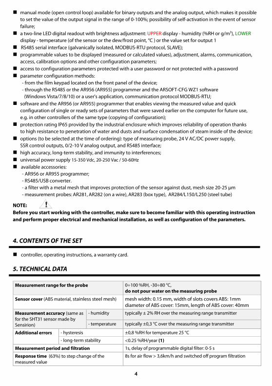
a) the numbers of the terminals and the method of connecting electrical wires - description of terminals Table 7
NOTE:
For connecting the device with a computer through the PRG socket, use only the AR956 or AR955 programmer.
Connection made with a regular USB cable may cause damage to the equipment.
8. IMPORTANT COMMENTS PERTAINING TO OPERATION – using the suppression systems
If an induction load is connected to the transmitter's contacts (e.g. a contactor coil or a transformer), when the
contacts open up there are frequent overvoltages and electrical arcs caused by the discharge of the energy
gathered in the induction. The particularly negative consequences of such overvoltages include reduced service
life of contactors and transmitters, damage to semiconductors (diodes, thyristors, and triacs), damage to or
interference with the control and measurement systems, and emission of electromagnetic field that interferes with
local devices. In order to avoid such consequences, the overvoltages must be reduced to a safe level. The simplest
method is to connect an appropriate suppression module directly to the terminals of the inductive load.
Generally speaking, appropriate types of suppression circuits must be selected for each type of inductive load.
Modern contactors are generally fitted with appropriate factory-made suppression circuits. If such circuits are
lacking, a contactor with an integrated suppression system must be purchased.
Temporarily, the load can be shunted with an RC system, e.g. R=47 Ω/1 W and
C=22 nF/630 V. The suppression circuit must be connected to the inductive load
terminals. The use of a suppression circuit limits burning of relays contacts in the
controller and reduces the likelihood of their sticking.
9. FUNCTIONS OF BUTTONS AND LED INDICATORS
Fig. 9. Description of the front panel
LED indicators
7-segment LED displays
programming buttons
a) button functions in the measurement display mode
Button Description [and marking in the contents of the instructions]
[UP] or [DOWN]: change of preset value for output 1 (parameter 13: St1 or 42: HSEt
when output 1 is in the manual mode, see chapters 10 and 12.7)
!
!

8
[SET] :
- go to the quick access menu (chapter 11)
[UP] and [DOWN] (at the same time): go to the parameter configuration menu (after hold
time longer than 1 s). If parameter 45: Prt = on (password protection is activated) enter
the access code (chapter 10)
[F]: activation of a function programmed with parameter 46: FbF (after holding for more
than 1 second, chapters 9.1 and 10)
b) button functions in the parameter configuration menu and the quick access menu (chapters 10 and 11)
Button Description [and marking in the contents of the instructions]
[SET]:
- selection of the item displayed in the configuration menu (entering a lower level)
- edits the current parameter (the value blinks in the lower display)
- approves and saves the edited parameter value
[UP] or [DOWN]:
- moves to the next or previous parameter (submenu)
- changes the value of the edited parameter
or
[UP] and [DOWN] (simultaneously) or [F]:
- returns to the previous menu (higher level)
- cancels changes to the edited value (the blinking stops)
- returns to the measurement display mode (only [UP] and [DOWN]
after hold time >0.5 s)
c) functions of the LED signaling diodes
Diode [marking] Description
1 2 3 signals switching on of outputs P1/SSR1, P2/SSR2, and P3/SSR3
%RH °C indicators of measurement units, green on for %RH, green off for g/m3, red °C )
9.1. FUNCTION BUTTON AND BINARY INPUT
The function button [F] and the binary input BIN have the same function, which is programmable with parameter
46: FbF (chapter 10). The binary input works with the bistate signal i.e. the supplied signal (voltage or switch) must
be permanent (on/off type). Moreover, button [F] is inactive when the input BIN is active (short circuit or voltage <
0.8 V). Activation or deactivation of the function is indicated by appropriate messages on the display (described
below in Table 9.1).
Table 9.1. Available functions of the [F] button and the BIN input
Source Description (depending on the value of parameter 46: FbF) Message
or
FbF = non button [F] and input BIN are inactive (default factory setting) -
FbF = St3
step-wise change of the preset value for the P1/SSR1 output
(day = parameter 13: St1 /night = 27: St3 , Table 10) St1 / St3
FbF = bLo keyboard lock (with the exception of button [F]) bLo / boF
FbF = hd1 unconditional manual mode for the P1/SSR1 output (chapter 12.7) hAn / hoF

9
or
FbF = hd2 unconditional manual mode for the P2/SSR2 output hAn / hoF
FbF = hd3 unconditional manual mode for the P3/SSR3 output hAn / hoF
FbF = hdA unconditional manual mode for the analog output hAn / hoF
FbF = StS control start/stop (applies to all outputs) Sta / Sto
FbF = rHt unconditional view of the values measured by the sensor (%RH,°C ) rHt / roF
10. SETTING OF THE CONFIGURATION PARAMETERS
All the controller's configuration parameters are saved in a non-volatile (permanent) internal memory.
There are two parameter configuration methods:
1. From the film keypad located on the front panel of the device:
- from the measurement display mode go to the configuration menu (simultaneously press the [UP] and
[DOWN] buttons simultaneously for more than 1 second) If parameter 45: Prt = on (password protection
is on) the display will show the message Cod , and then 000 with the first digit blinking, use the buttons
[UP] or [DOWN] to enter the access code (factory setting of parameter 44: PAS = 111 ), to move to successive
items and to approve the code, use the [SET] button
- after entering the main configuration menu (with the message CnF ) the upper display shows a mnemonic
name of the submenu (parameter groups: chH <-> chL <-> ot1 <-> etc.)
- use the[UP] or [DOWN] button to move to the relevant submenu and then use the [SET] button to approve
the selection (the name of the parameter is displayed in the upper display and the value - in the lower display)
- by pressing the [UP] button, you can move to the next parameter, and by pressing the [DOWN] button - to the
previous parameter (e.g. dPH <-> dtH <-> FLH <-> etc.; the list of the configuration parameters is presented
in Table 10)
- to change the value of the current parameter, press briefly the [SET] button (the parameter blinks in the
edition mode)
- use buttons [UP] or [DOWN] to change the value of the edited parameter
- approved the changed value of the parameter by pressing the [SET] button or cancel it by pressing the [F] or
[UP] and [DOWN] buttons (the latter two must be briefly pressed simultaneously) - by pressing the [UP] and
[DOWN] buttons or the [F] button again, you will return to the main configuration menu (a higher level)
- to exit the configuration: press the [UP] and [DOWN] buttons for a long moment or wait approx. 2 minutes
2. Use the RS485 or the PRG port (AR956/955 programmer) and the ARSOFT-CFG WZ1 software (chapter 14):
- connect the controller to a computer port, start and configure the ARSOFT-CFG WZ1 application;
- after the connection has been established, the current measured value is displayed in the window
of the softwares
- setting and viewing of the device parameters is possible in the parameter configuration window
- new parameter values must be approved with the Approve changes button
- the current configuration can be saved in a file or set using values read from a file
NOTE: !
- before disconnecting the device from a computer, press the Disconnect device button (ARSOFT-CFG WZ1)
- in the event of no response:
- in the Program options check the configuration of the port and the MODBUS Address of the device
- make sure that the serial port drivers in the computer have been properly installed for the RS485
converter or the AR956 (AR955) programmer
- disconnect for a few seconds and then reconnect the RS485 converter or the AR956 (AR955)
programmer
- restart the computer

10
In the event of indications different than the actual value of the relative humidity or the temperature of the sensor,
the zero and the sensitivity of a sensor can be tuned: parameters 3: coH and 8: cot, as well as 4: cGH and 9: cGt .
To restore the factory settings, when the power supply is switched on press buttons [UP] and [DOWN] and hold
them until the password menu appears (Cod), and then enter the following code 112. As an alternative, a file with
default configuration can be used in the ARSOFT-CFG WZ1 software.
NOTE: !
Do not perform configuration of the device with the keypad and through the serial interface (RS485 or AR956/955)
at the same time.
Table 10. List of configuration parameters
Parameter Range of variability of the parameter and description Factory
settings
HUMIDITY CHANNEL DISPLAY CONFIGURATION (upper display) - submenu chH
0: dPH value for the upper
display
rHu measured relative humidity [%RH] rHu
AHu calculated absolute humidity [g/m3]
1: dtH resolution of
humidity indications
0 resolution 1 %RH or g/m3 1
(0.1 %RH) 1 resolution 0.1 %RH or g/m3
2: FLH filtration (1) 1 ÷ 10 digital filtration of measured humidity (response time) 3
3: coH calibration
of the zero ± 20.0 %RH zero shift for the measured absolute humidity 0.0 %RH
4: cGH calibration of the
inclination /5.0 ÷ 15.0 % amplification (sensitivity) correction for relative humidity 0.0 %
LOWER CHANNEL DISPLAY CONFIGURATION (temperature or set value for output 1) - submenu chL
5: dPL value for the lower
display
StE measured sensor temperature [°C]
StE dPt calculated dew/frost point temperature [°C]
St1 set value for output 1 (13: St1 or 42: HSt in manual mode,
chapter 12.7)
6: dtt resolution of
temperature indications
0 resolution of 1 °C for temperature 1
(0.1 °C) 1 resolution of 0.1 °C for temperature
7: FLt filtration (1) 1 ÷ 10 digital filtration of measured temperature (response time) 3
8: cot calibration of the
zero ± 20.0 °C zero shift for the measured sensor temperature 0.0 %RH
9: cGt calibration of the
inclination /5.0 ÷ 15.0 %
amplification (sensitivity) correction for the sensor
temperature 0.0 %
MAIN OUTPUT CONFIGURATION (P1/SSR1) – submenu ot1 - chapter 12 (12.2)
10: cS1 control signal for
output 1
rHu measured relative humidity [%RH]
rHu AHu calculated absolute humidity [g/m3]
StE measured sensor temperature [°C]
dPt calculated dew/frost point temperature [°C]
11: Ft1 failure status of
output 1 (2)
output status in the case of lack of or damage to the measurement sensor:
nCh = no change, oFF = switched off, on = switched on, hnd = manual mode
with set output signal level (parameter 42: HSt , chapter 12.7)
oFF
12: Fn1 function of
output 1 (chapter 12.2)
oFF = switched off, hnd = manual mode, inv = reverse control (heating or
humidification), dir = direct control (cooling or drying) inv

11
13: St1 preset value 1 set value for output 1, changes in the range of 15: Lo1 - 16: Hi1 50.0 %RH
14: H1 hysteresis of output
1 or PID tuning zone 0.0 ÷ 99.9
hysteresis for control of the ON-OFF type or insensitivity zone
of PID tuning in the auto mode ( Aut ), chapter 12.5 1.0 %RH
15: Lo1 lower setting limit -30 ÷ 100 lower setting limit for the preset value 1: 13: St1 -30 %RH
16: Hi1 upper setting limit -30 ÷ 100 upper setting limit for the preset value 1: 13: St1 100 %RH
CONFIGURATION OF AUXILIARY OUTPUTS (P2/SSR2 and P3/SSR3) – submenu ot2 for output 2 and analogously ot3
for output 3 - chapter 12 - the parameters for output 2 are shown below
17: cS2 control signal for
output 2
rHu measured relative humidity [%RH]
StE AHu calculated absolute humidity [g/m3]
StE measured sensor temperature [°C]
dPt calculated dew/frost point temperature [°C]
18: Ft2 failure status of
output 2 (2)
output status in the case of lack of or damage to the measurement sensor:
nCh = no change, oFF = switched off, on = switched on, hnd = manual mode
with set output signal level (parameter 42: HSt , chapter 12.7)
oFF
19: Fn2
function of output 2
(chapter 12.2)
oFF = switched off, hnd = manual mode, inv = reverse control (heating or
humidification), dir = direct control (cooling or drying)
bon or boF = band ± St2 ( St3 for output 3 ) around St1 ,
doF or don = deviation from St1
inv
( oFF
for output
3)
20: St2 preset value 2 set value for output 2, changes in the range of 22: Lo2 - 23: Hi2 50.0 °C
21: H2 hysteresis of output
2 0.0 ÷ 99.9 hysteresis of output 2 for ON-OFF type of control 1.0 °C
22: Lo2 lower setting limit -30 ÷ 100 lower setting limit for the preset value 2: 20: St2 -30 °C
23: Hi2 upper setting limit -30 ÷ 100 upper setting limit for the preset value 2: 20: St2 100 °C
ANALOG OUTPUT CONFIGURATION – submenu outA - (chapter 12.3)
31: rSA control signal for
analog output in the
measurement
retransmission mode
(parameter 33: FnA = rEt )
rHu measured relative humidity [%RH]
rHu AHu calculated absolute humidity [g/m3]
StE measured sensor temperature [°C]
dPt calculated dew/frost point temperature [°C]
32: AtY type of analog
output
depending on the order code: for current output 0-20 mA ( 020 ) or 4-20 mA
( 420 ), for voltage output 0-10 V ( 010 ) or 2-10 V ( 210 )
020 mA
(010 V)
33: FnA function of analog
output
oFF = off, hnd = manual mode, rEt = retransmission of measurement, ot1
= control output, detailed description in chapter 12.3 oFF
34: LoA lower indication for
retransmission -30 ÷ 100
start of the output scale - for 0/4 mA or 0/2 V (the parameter is
active only for measurement retransmission when 33: FnA =
rEt )
0.0 %RH
35: HiA upper indication
for retransmission -30 ÷ 100
end of output scale - for 20 mA or 10 V (the parameter is
active only for measurement retransmission when 33: FnA =
rEt )
100 %RH
CONFIGURATION OF THE PID ALGORITHM AND THE MANUAL MODE – submenu Pid
36: tun type of PID tuning
(chapter 12.5)
oFF off
oFF Aut automatic selection (continuous tuning)
StP run-up method (fast)
oSc oscillation method (longer)

12
37: Pb range of PID
proportionality 0 ÷ 200
0 - switches off the PID's action, a description of the PID
algorithm and associated topics can be found in chapters
12.4 ÷ 12.6
0.0 %RH
38: ti PID integration time
constant 0 ÷ 999 s
PID algorithm doubling time
0 switches off the integrating component of the PID
algorithm
0 s
39: td PID differentiation
time constant 0 ÷ 999 s
PID algorithm lead time
0 switches off the differentiating component of the PID
algorithm
0 s
40: PoC PID signal
correction 0 ÷ 100 % increase of the level of the control signal for the PID algorithm 0 %
41: tc impulse period 3 ÷ 360 s for bistable outputs (1, 2, 3) in the manual mode and the PID 5 s
42: HSt preset value of the
manual mode
0 ÷ 100 %
1% step
control value for outputs in the manual mode, applies to all
outputs (1, 2, 3, and the analog output), chapter 12.7 50 %
ACCESS OPTIONS – submenu Acc
43: bSEt value change
block for St1 , St2 , St3
oFF = no block, St1 = block of parameter 13: St1 , St2 = block 20: St2 ,
St3 = block 27: St3 , ALL = simultaneous block of changes St1 , St2 and St3 oFF
44: PAS password 000 ÷ 999 password for the parameter configuration menu 111
45: Prt protection of the
configuration with a
password
oFF entry into the configuration menu is not password-protected
on on entry into the configuration menu is password-protected
COMMUNICATION OPTIONS AND OTHER CONFIGURATION PARAMETERS – submenu oth
46: FbF
function of the [F] button
and the BIN input
(chapter 9.1)
non button [F] and input BIN are inactive
non
St3 change of the preset value (day/night) for output 1
bLo keyboard lock (with the exception of button [F])
hd1 unconditional manual mode for output 1 (P1/SSR1)
hd2 unconditional manual mode for output 2 (P2/SSR2)
hd3 unconditional manual mode for output 3 (P3/SSR3)
hdA unconditional manual mode for the analog output
StS control start/stop (applies to all outputs)
rHt unconditional view of the values measured by the sensor
(%RH,°C )
47: Add MODBUS-RTU
address 1 ÷ 247
individual address of the device in the RS485 network (chapter
16) 1
48: br baud rates for RS485
and PRG port 2.4 kbit/s 4.8 kbit/s 9.6 kbit/s 19.2 kbit/s 38.4 kbit/s 57.6 kbit/s 19.2 kbit/s
49: brG illumination
brightness 30 ÷ 100 % brightness of the display, a 10% increase 100 %
Notes: (1) – for FLH or FLt = 1 the response time is equal to 1 second; for FLH or FLt = 10 it is at least 5 seconds..
Higher degree of filtration means a more "smooth" measured value and a longer response time, which is
recommended in the case turbulent measurements.
(2) – the parameter also defines the state of the output outside of the measurement range

13
11. QUICK ACCESS MENU
In the measurement mode (when the measured or the calculated values is displayed), it is possible to immediately
access certain configuration parameters and functions without the need to enter a password. This possibility is
offered by the quick menu, which can be accessed by pressing the [SET] button. The parameter is selected and
edited in the same way as described above (in chapter 10).
Table 11. List of elements accessible in the quick configuration menu.
Element Description
St1
preset value 1 (parameter 13: St1 ), optional element - unavailable when parameter 12: Fn1 = hnd , changes
blocked during selection of parameters (tuning) of the PID (chapter 12.5) and in the mode of change of the
preset value 1 (ST1) to 3 (ST3) chapter 9.1
St2 preset value 2 (20: St2 ), optional element - unavailable when parameter 19: Fn2 = oFF or hnd
St3 preset value 3 (27: St3 ), optional element - unavailable when parameter 26: Fn3 = oFF or hnd
tSt start/stop of PID tuning (chapter 12.5), optional element - unavailable when parameter 36: tun = oFF
HSt preset value of the manual mode (42: HSt ), optional element - available for outputs in the manual operation
mode
12. OUTPUT OPERATION CONFIGURATION
The programmable architecture of the controller enables using it in many fields and applications. Before the
operation of the device starts, it is necessary to set the parameters according to specific requirements (chapter 10).
A detailed description of configuration of the operation of outputs is given in chapters 12.1÷ 12.7.
The default (factory) configuration is the following: output 1 is connected with relative humidity (%RH), output 2 -
with sensor temperature (°C ), the ON/OFF configuration mode with hysteresis, output 3 and the analog outputs
are switched off (Table 10, Factory settings column).
12.1. CHANGING THE PRESET OUTPUT VALUES
The simplest way to change the preset value for output 1 (parameter 13: St1 or 42: HSt when output 1 is in the
manual mode) is to use the [UP] button or the [DOWN] button in the measured value display mode. In the case of
the other outputs, the quick menu can be used (chapter 11). As an alternative, it is possible to change the preset
value in the parameter configuration mode (using the methods described in chapter 10).
12.2. TYPES OF OUTPUT CHARACTERISTICS
The mode of operation of each output is programmed using parameters 12: Fn1 , 19: Fn2 and 26: Fn3 , chapter 10,
Table 10.
a) basic operating characteristics of outputs

14
b) additional operating characteristics of outputs (applies only to outputs 2 and 3)
12.3. ANALOG OUTPUT
The standard of the output signal is determined by parameter 32: AtY (chapter 10, Table 10). The analog output
can work in one of the following modes: retransmission of measurement (parameter 33: FnA = rEt ), in the manual
mode (33: FnA = hnd ) and as an automatic control output (33: FnA = ot1 ).
In the mode of retransmission of selected measurement (31: rSA ), the output signal is proportional to the
measured signal in the range set by parameters 34: LoA and 35: HiA (e.g. 0 mA for the measured value 0 °C when
LoA = 0 °C, 20 mA for 100 °C when HiA = 100 °C and, as appropriate, 10 mA for the half of the range, i.e. 50°C ).
Manual operation (chapter 12.7) enables smooth change of the output signal in the range of 0-100% with an
increment of 1% and the initial value equal to the last value in the automatic mode (measurement retransmission
or control mode).
In the control output mode, the control parameters and their functions are identical as in the case of output 1 (the
applicable parameters are 10: cS1 , 11: Ft1 , 12: Fn1 , 13: St1 , 14: H1, and the PID algorithm and tuning
parameters). In the control mode, the range of variability of the analog signal is continuous only for the PID
algorithm (with regards to proportionality, chapter 12.4), in the case of ON-OFF control with hysteresis, the output
assumes limit values (lower or upper, e.g. 0 mA or 20 mA), without intermediate values.

15
12.4. PID REGULATION
The PID algorithm enables achieving smaller control errors (temperature
or humidity) than the ON-OFF method with hysteresis. However, the
algorithm requires selecting the characteristic parameters for the specific
controlled object (e.g. a furnace). In order to simplify the operation, the
controller is provided with the advanced PID parameter selection
functions described in chapter 12.5. Also, it is always possible to
manually correct the settings (chapter 12.6).
The controller works in the PID mode when the proportionality range
(parameter 37: Pb ) is not a zero value. The location of the proportionality
range Pb in relation to the preset value (parameter 13: St1 ) is shown in
figures 12.4 a) and b). The impact of the integrating and differentiating
components of PID regulation is determined by parameters 38: ti and
39: td . Parameter 41: tc determines the impulse period for output 1
(P1/SSR1). If the PID algorithm is implemented by the 0/4-20 mA or 0/2-
10 V analog output, parameter 41: tc is irrelevant. Then the output signal
may assume intermediate values from the entire range of variability of
the output.
Regardless of the type of the output, the correction of its state always
takes place every 1 s.
The principle of P-type regulation (proportional regulation) for output 1
is shown in figures d) and e) for the analog output figure c).
In the case of type P and PD control, the value of the process
(temperature or humidity) usually does not reach the set value and
becomes stabilized on a certain deviation level. In order to eliminate this
deviation, correction of the output signal may be useful; it is achieved
with parameter 40: PoC .
Fig. 12.4. Principle of the PID regulation:
a) location of the proportionality range Pb in relation to the preset value
St1 for heating or humidification (parameter 12: Fn1 = inv )
b) location of the proportionality range Pb in relation to the preset value
St1 for cooling or drying (parameter 12: Fn1 = dir )
c) state of the 0/4÷20 mA or 0/2÷10 V analog output
d) filling coefficient for output 1 (P1/SSR1)
e) state of output 1 (for the measured value within the proportionality
range)
12.5. AUTOMATIC PID PARAMETER SELECTION
The first step to use the PID parameter selection function is to choose the type of tuning (parameter 36: tun ,
chapter 10). The tuning is started automatically when the regulation starts (after the power supply is switched on,
and by pressing the [F] function button or the BIN binary input, when parameter 45: FBF = StS , chapter 9.1).
Moreover, the tuning can be stopped ( oFF ), and then started ( on ) at any time using the tSt function available in
the quick menu (chapter 11). During the tuning (when the display shows, alternately with the measured value, the
message tvn ) the preset value must not be changed (13: St1 or 27: St3 when 46: FbF = St3 ).
The value of parameter 36: tun determines the choice of the PID parameter selection method:
a) 36: tun = Aut - automatic selection - the controller continuously checks if there are appropriate conditions for

16
starting the tuning and tests the object in order to select the proper method. The algorithm continuously forces
operation in the PID mode. The necessary condition for initiating the PID parameter selection procedure is that
the current measured value must be located outside of the insensitivity zone defined as the sum of the values of
parameter 37: Pb and 14: H1 in relation to the preset value 13: St1 , as shown in figure 12.5.
Fig. 12.5. Location of the insensitivity zone for
heating/humidification (12: Fn1 = inv ) and
cooling/drying (12: Fn1 = dir ).
In order to avoid unnecessary activation of tuning, which may slow down the process, it is recommended to set
the highest possible value of H1, not less than 10-30% of the range of variability of the process (the temperature
or the humidity). Testing of the object with temporary switchoff of the output and the tun message also takes
place in the insensitivity band if sudden changes in the measured value or preset value are detected.
The choice of the parameter selection method depends on the nature of the initial conditions. In the case of a
stabilized controlled value, the run-up (quick) method will be selected; in other cases, the oscillation method
(slower) will be selected.
Automatic selection enables optimum selection of the PID parameters for the current conditions at the object,
without the user's involvement. It is recommended for variable value regulation (disturbance of the conditions
determined during the operation due to the change of, e.g. the preset value or the weight of the furnace batch).
b) 36: tun = StP – selection of parameters in the run-up phase (response to step forcing function). During
determination of the object's characteristics, the algorithm does not cause any additional delay in reaching the
preset value. This method is intended specifically for objects of stabilized initial value of the controlled value
(e.g. temperature in a cold furnace). In order to avoid disturbing stabilized initial conditions, before the
automatic tuning is switched on, the power supply of the operating element (e.g. a heater) should be switched
off using an external connector or the regulation start/stop function should be used (the [F] button or the BIN
input). The power supply must be switched on immediately after the tuning is started, in the output switch-on
delay phase. If the power supply is switched on later, an erroneous analysis of the object and improper selection
of PID parameters will result.
c) 36: tun = oSc – selection of parameters using the oscillation method. The algorithm consists in measuring the
amplitude and the period of oscillation on a slightly lower level (in the case of heating/humidification) or higher
level (in the case of cooling/drying) than the preset value, thus eliminating the risk of exceeding the target value
at the object testing stage. During determination of the object's characteristics, the algorithm causes additional
delays in reaching the preset value. This method is intended specifically for objects of unstable initial value of
the controlled value (e.g. temperature in a hot furnace).
The algorithms described in items b and c comprise the following steps:
- delay of output switch-on (approx. 15 s) - time for switching on the power supply of the operating element
(heating/cooling power, fan, etc.)
- determination of the object's characteristics
- calculation and saving in the controller's permanent memory parameters 37: Pb , 38: ti , 39: td and 41: tc
- switching on the regulation with new PID settings;
Programmed interruption of automatic tuning b or c (with the message Ert ) may take place if the conditions are
not met for correct operation of the algorithm, such as:
- the initial value is higher than the preset value for heating/humidification or lower than the preset value for
cooling/drying;
- the maximum tuning time (4 hours) has been exceeded;
- the process value is changing too fast or too slowly.
It is recommended to restart the automatic tuning b or c after a significant change in the St1 threshold or the
controlled object's parameters (e.g. the heating/cooling power, the batch weight, the initial temperature, etc.).

17
12.6. PID PARAMETER CORRECTION
The automatic tuning function correctly selects the PID regulation parameters for most processes; however,
sometimes it may be necessary to correct them. Due to the strong correlation between those parameters, only
one parameter should be changed and the impact of the change on the process should be observed:
a) oscillations around the threshold - increase the range of proportionality 37: Pb , increase the integration time
38: ti , reduce the differentiation time 39: td , (or change by a half the impulse period of output 1, parameter 41:
tc )
b) slow response - decrease the range of proportionality Pb , differentiation times td and integration times ti
c) over-regulation - increase the range of proportionality Pb , differentiation times td and integration times ti
d) instability - increase the integration time ti .
12.7. MANUAL AND REMOTE CONTROL FUNCTION
The manual mode enables setting the value of the output signal in the entire range of its variability (0-100%), thus
enabling operation in an open regulation loop (no automatic coupling between the measured value and the
output signal). Manual operation is available individually for each output of the controller and is programmed
using parameters 12: Fn1 , 19: Fn2 , 26: Fn2 and 33: Fn3 , chapter 10, Table 10. Also, the outputs can be configured
for quick (unconditional) manual mode controlled by:
- the [F] function button or the binary BIN input, by programming, as appropriate, parameter 46: FbF (chapter
9.1),
- measurement error of the sensor (range exceeded or defect) when 11: Ft1 , 18: Ft2, or 25: Ft3 is equal to hnd
In the case of bistable outputs (1, 2, 3), the change of the output signal consists in setting the filling coefficient
(using parameter 42: HSt ) with impulse period defined by parameter 41: tc . The preset value of the manual mode
42: HSt = 0 stands for a permanently switched off output; value 100 stands for a permanently switched on output.
The value can be set directly using the [UP] or [DOWN] button (only in the case of output 1, chapter 12.1) or using
the quick menu (chapter 11), or alternatively, in the parameter configuration mode (from the membrane keypad or
remotely using the RS485 or PRG serial port, chapters 10, 14-16 ).
13. MESSAGE AND ERROR SIGNALING
a) measurement errors:
Code Possible causes of error
^^^ the measurement range of the sensor is exceeded from the top
___ the measurement range of the sensor is exceeded from the bottom
--- no communication with the sensor (the sensor is defective or the electrical connections are broken)
b) temporary messages and errors (one-time and recurring):
Code Description of message
Cod mode of entering the password for access to the configuration parameters, chapter 10
Err the password is invalid
CnF access to the parameter configuration menu
tun implementation of the PID automatic tuning function, chapter 12.5
Ert automatic tuning error, chapter 12.5, error deletion using the [UP] and [DOWN] buttons (pressed
simultaneously)
StA / Sto regulation start/stop, chapter 9.1
St1 / St3 change of the preset value (day/night) for output 1, chapter 9.1

18
bLo / boF keypad block on/off, chapter 9.1
hAn / hoF unconditional manual mode on/off, chapter 9.1
SAU saving of factory parameter values (chapter 10)
14. CONNECTING THE CONTROLLER TO A COMPUTER AND AVAILABLE SOFTWARE
It may be useful (or necessary) to connect the controller to a computer in the following situations:
- remote monitoring and recording of current measurement data and process (status of the outputs) control;
- quick configuration of parameters, to include copying of settings to other controllers of the same type
In order to establish communication over long distances, it is necessary to establish a connection in the RS485
standard with an available port in the computer (directly or using an RS485 converter), as described in chapter 15.
Moreover, as a standard, the controllers are equipped with a PRG port which enables connecting to a computer
using an AR956/955 programmer (without galvanic separation, cable length approx. 1.2 m). Both the programmer
and the RS485 converter require installation of the supplied serial port drivers on the computer. Communication
with devices is effected using a protocol compatible with MODBUS-RTU (chapter 16). The following applications
are available (on a CD supplied with the AR956/955 programmer or to be downloaded from the Internet at
www.apar.pl, Download section, for operating systems Windows Vista/7/8/10):
Name Software description
ARSOFT-CFG WZ1
(free)
- display of current measurement data from the connected device
- configuration of measurement channels, settings ranges, control options, alarms, display,
communication, access, etc. (chapter 10)
- creation on the disk of a "cfg" file with the current configuration of the parameters for
future use (copying of configuration)
- the program requires communication with the controller via the RS485 or PRG
(AR956/955) port
ARSOFT-WZ2
(payable)
- display and recording of current measurement data from a maximum of 30 channels (only
from devices made by APAR)
- the program requires communication with the controller via the RS485 or PRG
(AR956/955) port
The detailed descriptions of the aforementioned applications can be found in the installation folders.
NOTE: !
Before establishing the connection, make sure that the MODBUS address of the device (parameter 47: Add ) and
the speed of transmission (48: br ) are the same as the settings of the software. Moreover, in the software, set the
number of the COM serial port in use (in the case of the RS485 converter or the AR956/955 programmer it is the
number assigned by the operating system during installation of the drivers).
15. RS485 COMMUNICATION INTERFACE (acc. to EIA RS-485)
The installation specification for the RS485 interface is the following:
- maximum cable length - 1 km (observe the installation guidelines, chapter 2, sub-items b, c, and d)
- maximum number of devices in a RS485 line - 30, in order to increase the number, use RS485/RS/485 amplifiers
- termination and polarizing resistors when the MASTER is at the start of the line (Fig. 15):
- at the start of the line - 2 x 820 Ω to the ground and +5 V of the MASTER and 150 Ω between lines
- at the end of the line - 150 Ω between lines
- termination and polarizing resistors when the MASTER is in the center of the line:
- at the converter - 2 x 820 Ω, to the ground and +5 V of the converter

19
- at both ends of the line - 150 Ω each between lines
Equipment from different manufacturers that form the RS485 network (e.g. RS485 converters/USB) may have
integrated polarizing and terminating resistors; in such a case there is no need to use external elements.
Fig. 15. Pictorial diagram of the RS485 network
16. MODBUS–RTU SERIAL TRANSMISSION PROTOCOL (SLAVE)
Character format : 8 bits, 1 stop bit, no parity bit
Available functions : READ - 3 or 4, WRITE - 6
Table 16.1. Claim frame format for the READ function (frame length - 8 bytes):
address of
the device
function
4 or 3
read register address:
0 ÷ 65 (0x0041)
number of read registers:
1 ÷ 16 (0x0010) CRC check sum
1 byte 1 byte 2 bytes (HB-LB) 2 bytes (HB-LB) 2 bytes (LB-HB)
Example 16.1. Reading of a register with address 0: 0x01 - 0x04 - 0x0000 - 0x0001 - 0x31CA
Table 16.2. Claim frame format for the WRITE function (frame length - 8 bytes):
address of
the device function 6
write register address:
0 ÷ 65 (0x0041)
write register value
CRC check sum
1 byte 1 byte 2 bytes (HB-LB) 2 bytes (HB-LB) 2 bytes (LB-HB)
Example 16.2. Entry in a register with address 10 (0xA) with the 0 value: 0x01 - 0x06 - 0x000A - 0x0000 - 0xA9C8
Table 16.3. Response frame format for the READ function (minimum frame length - 7 bytes):
address of
the device
function
4 or 3
number of bytes in the
data field (max. 16*2=32
bytes)
data field - register value CRC check sum
1 byte 1 byte 1 byte 2 ÷ 32 bytes (HB-LB) 2 bytes (LB-HB)
Example 16.3. Response frame for register value equal to 0: 0x01 - 0x04 - 0x02 - 0x0000 - 0xB930
Table 16.4. Response frame format for the WRITE function (frame length - 8 bytes):
copy of the claim frame for the WRITE function (Table 16.2)
Table 16.5. Special answer (errors: function field = 0x84 or 0x83 in the case of the READ function and 0x86 in the
case of the WRITE function):
Error code (HB-LB in the data field) Error description
0x0001 non-existing register address
0x0002 wrong write register value
0x0003 improper function number

20
Example 16.5. Error frame for a non-existing read register address:
0x01 - 0x84 - 0x02 - 0x0001 –0x5130
Table 16.6. Map of registers for the MODBUS-RTU protocol
Register
address
HEX (DEC)
Value
(HEX or DEC)
Description of register and access type
(R- read only register, R/W - read and write register)
0x00 (0) 0 not used or reserved R
0x01 (1) 2470 device type identifier (AR247) R
0x02 (2) 10 ÷ 99 controller software (firmware) version R
0x03 ÷ 0x05 0 not used or reserved R
0x06 (6) 0 ÷ 7 current status of outputs 1, 2, 3: bits 2, 1, 0, bit=1 means the output is
switched on R
0x07 (7) 0 ÷ 20000 current state of the analog output (0 ÷ 20000 μA or 0 ÷ 10000 mV) R
0x08 (8) 0 not used or reserved R
0x09 ÷ 0x0C -300 ÷ 1000 measured and calculated values (relative humidity %RH, g/m3, ambient
temperature °C, dew point °C), resolution 0.1, code U2 (16-bit) R
0x0D (13) -300 ÷ 1000 current preset value for output 1 R
0x0E ÷ 0x0F 0 not used or reserved R
Configuration parameters (chapter 10, Table 10)
0x10 (16) 0 ÷ 1 parameter 0: dPH value indicated for the upper display R/W
0x11 (17) 0 ÷ 1 parameter 1: dtH resolution of humidity indications R/W
0x12 (18) 0 ÷ 10 parameter 2: FLH digital filtration of measured humidity (response time) R/W
0x13 (19) -200 ÷ 200 parameter 3: coH zero shift for the measured absolute humidity R/W
0x14 (20) -150 ÷ 150 parameter 4: cGH amplification (sensitivity) correction for relative humidity R/W
0x15 (21) 2 ÷ 4 parameter 5: dPL value indicated for the lower display R/W
0x16 (22) 0 ÷ 1 parameter 6: dtt resolution of temperature indications R/W
0x17 (23) 0 ÷ 10 parameter 7: FLt digital filtration of measured temperature (response time) R/W
0x18 (24) -200 ÷ 200 parameter 8: FLt zero shift for the measured sensor temperature R/W
0x19 (25) -150 ÷ 150 parameter 9: FLt amplification (sensitivity) correction for the sensor temperature R/W
Configuration parameters of outputs 1, 2, and 3 ( output index KA = 0-2, KA=0=output 1, KA=1=output 2, KA=2=output 3)
0x1A (26) +KA*7 0 ÷ 3 parameter 10+KA*7: cS control signal for output (1, 2, or 3) R/W
0x1B (27) +KA*7 0 ÷ 3 parameter 11+KA*7: Ft failure status of output (1, 2, or 3) R/W
0x1C (28) +KA*7 0-3 or 0-7 parameter 12+KA*7: Fn function of output (1, 2, or 3) R/W
0x1D (29) +KA*7 -300 ÷ 1000 parameter 13+KA*7: St preset value (1, 2, or 3) R/W
0x1E (30) +KA*7 0 ÷ 999 parameter 14+KA*7: H hysteresis of output (1, 2, or 3) R/W
0x1F (31) +KA*7 -300 ÷ 1000 parameter 15+KA*7: Lo lower setting limit for the preset value (1, 2, or 3) R/W
0x20 (32) +KA*7 -300 ÷ 1000 parameter 16+KA*7: Lo upper setting limit for the preset value (1, 2, or 3) R/W
0x2F (47) 0 ÷ 3 parameter 31: rSA control signal for the analog output (for retransmission) R/W
0x30 (48) 0 ÷ 1 parameter 32: AtY type of analog output R/W
0x31 (49) 0 ÷ 3 parameter 33: FnA function of analog output R/W
0x32 (50) -300 ÷ 1000 parameter 34: LoA lower indication for retransmission R/W
0x33 (51) -300 ÷ 1000 parameter 35: HiA upper indication for retransmission R/W
0x34 (52) 0 ÷ 3 parameter 36: tun type of PID tuning R/W
0x35 (53) 0 ÷ 2000 parameter 37: Pb range of PID proportionality R/W
0x36 (54) 0 ÷ 999 parameter 38: ti PID integration time constant R/W

21
0x37 (55) 0 ÷ 999 parameter 39: td PID differentiation time constant R/W
0x38 (56) 0 ÷ 100 parameter 40: PoC correction of the output signal for the PID control algorithm R/W
0x39 (57) 3 ÷ 360 parameter 41: tc impulse period R/W
0x3A (58) 0 ÷ 100 parameter 42: HSt preset value of the manual mode R/W
0x3B (59) 0 ÷ 3 parameter 43: bSE value change block St1 , St2, St3 R/W
0x3C (60) 0 ÷ 999 parameter 44: PAS password R/W
0x3D (61) 0 ÷ 1 parameter 45: Prt protection of the configuration with a password R/W
0x3E (62) 0 ÷8 parameter 46: FbF function of the [F] button and the BIN input R/W
0x3F (63) 1 ÷ 247 parameter 47: Add MODBUS-RTU address in the RS485 network R/W
0x40 (64) 0 ÷ 6 parameter 48: br baud rate for RS485 R/W
0x41 (65) 30 ÷ 100 parameter 49: brG brightness of the display, a 10% increase R/W
17. NOTES
22
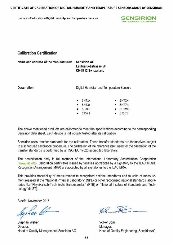
CERTIFICATE OF CALIBRATION OF DIGITAL HUMIDITY AND TEMPERATURE SENSORS MADE BY SENSIRION