Operating Instructions and Parts Manual JBG-W Series ...
24
Operating Instructions and Parts Manual JBG-W Series Grinder with Wire Wheel Models JBG-6W, JBG-8W JET 427 New Sanford Road LaVergne, Tennessee 37086 Part No. M-577126 Ph.: 800-274-6848 Edition 2 04/2018 www.jettools.com Copyright © 2018 JET
Transcript of Operating Instructions and Parts Manual JBG-W Series ...

1
Operating Instructions and Parts Manual JBG-W Series Grinder with Wire Wheel Models JBG-6W, JBG-8W
JET 427 New Sanford Road LaVergne, Tennessee 37086 Part No. M-577126 Ph.: 800-274-6848 Edition 2 04/2018 www.jettools.com Copyright © 2018 JET
Tom Gauger
This .pdf document is bookmarked

2
1.0 IMPORTANT SAFETY INSTRUCTIONS
WARNING – To reduce risk of injury:
1. Read and understand the entire owner's manual before attempting assembly or operation.
2. Read and understand the warnings posted on the machine and in this manual. Failure to comply with all of these warnings may cause serious injury.
3. Replace warning labels if they become obscured or removed.
4. This bench grinder is designed and intended for use by properly trained and experienced personnel only. If you are not familiar with the proper and safe operation of a bench grinder, do not use until proper training and knowledge have been obtained.
5. Do not use this bench grinder for other than its intended use. If used for other purposes, JET disclaims any real or implied warranty and holds itself harmless from any injury that may result from that use.
6. Always wear protective eye wear when operating machinery. Eye wear shall be impact resistant, protective safety glasses with side shields which comply with ANSI Z87.1 specifications. Use of eye wear which does not comply with ANSI Z87.1 specifications could result in severe injury from breakage of eye protection. (Everyday eyeglasses only have impact resistant lenses; they are NOT safety glasses.) Use the grinder’s eye shields and spark guards. Also use face or dust mask if cutting operation is dusty.
7. Wear proper apparel. Do not wear loose clothing, neckties, rings, bracelets, or other jewelry which may get caught in moving parts. Non-slip footwear is recommended. Wear protective hair covering to contain long hair.
8. Wear protective clothing such as apron or safety shoes, where the grinding activity presents a hazard to the operator.
9. Wear ear protectors (plugs or muffs) if sound exceeds safe levels.
10. CALIFORNIA PROPOSITION 65 WARNING: This product contains chemicals known to the State of California to cause cancer, or birth defects or other reproductive harm.
11. This product, when used for welding, cutting, or working with metal, produces fumes, gases, or dusts which contain chemicals known to the State of California to cause birth defects and, in some cases, cancer. (California Health and Safety Code Section 25249.5 et seq.)
12. Do not operate this machine while tired or under the influence of drugs, alcohol or any medication.
13. Make certain the switch is in the OFF position before connecting the machine to the power supply.
14. Make certain the machine is properly grounded.
15. Make all machine adjustments or maintenance with the machine unplugged from the power source.
16. Remove adjusting keys and wrenches. Form a habit of checking to see that keys and adjusting wrenches are removed from the machine before turning it on.
17. Keep safety guards in place at all times when the machine is in use. If removed for maintenance purposes, use extreme caution and replace the guards immediately after completion of maintenance.
18. Check damaged parts. Before further use of the machine, a guard or other part that is damaged should be carefully checked to determine that it will operate properly and perform its intended function. Check for alignment of moving parts, binding of moving parts, breakage of parts, mounting and any other conditions that may affect its operation. A guard or other part that is damaged should be properly repaired or replaced.
19. Provide for adequate space surrounding work area and non-glare, overhead lighting.
20. Keep the floor around the machine clean and free of scrap material, oil and grease.
21. Keep visitors a safe distance from the work area. Keep children away.
22. Make your workshop child proof with padlocks, master switches or by removing starter keys.
23. Give your work undivided attention. Looking around, carrying on a conversation and “horse-play” are careless acts that can result in serious injury.
24. Keep proper footing and balance at all times so that you do not fall into or lean against the grinding wheel or other moving parts. Do not overreach or use excessive force to perform any machine operation.
25. Disconnect grinder before servicing and before changing wheels.

3
26. Use recommended accessories. The use of improper accessories may cause risk of injury to persons.
27. Turn off the machine before cleaning. Use a brush to remove chips or debris — do not use bare hands.
28. Never leave the grinder running unattended. Turn power off and do not leave machine until wheels come to a complete stop.
29. Remove loose items and unnecessary work pieces from the area before starting the grinder.
30. Don’t use in dangerous environment. Don’t use power tools in damp or wet location, or expose them to rain. Don’t use this grinder in a flammable environment. Keep work area well lighted.
31. Keep work area clean. Cluttered areas and benches invite accidents.
32. Use right tool. Don't force tool or attachment to do a job for which it was not designed.
33. Use proper extension cord. Make sure your extension cord is in good condition. When using an extension cord, be sure to use one heavy enough to carry the current your product will draw. An undersized cord will cause a drop in line voltage resulting in loss of power and overheating. Sect. 6.2, Table 2 shows the correct size to use depending on cord length and nameplate ampere rating. If in doubt, use the next heavier gage. The smaller the gage number, the heavier the cord.
34. Maintain tools with care. Keep tools sharp and clean for best and safest performance. Follow instructions for lubricating and changing accessories.
35. Never stand on tool. Serious injury could occur if the tool is tipped or if the cutting tool is unintentionally contacted.
36. Direction of feed. Feed work into a blade or cutter against the direction of rotation of the blade or cutter only.
37. Do not overtighten wheel nut.
38. Frequently clean grinding dust from around and beneath grinder.
39. Use grinding wheels suitable for speed of grinder.
40. Inspect abrasive wheels for cracks or other forms of damage. Perform a “ring test” to check wheel integrity. Do not use a faulty or damaged wheel.
41. Verify that maximum RPM of abrasive or wire wheel is compatible with speed of grinder. Do not remove the blotter (label) from either side of a grinding wheel.
42. Allow machine to reach full RPM before starting the grinding operation.
43. Do not crowd the work so that the wheel slows.
44. Tool rest should be adjusted to approximately 1/16” from wheel surface.
45. Do not grind on the side of a wheel; do all work on the grinding face or edge near the tool rest.
46. Do not grind aluminum or magnesium on the grinding wheel, as these may pose a fire/safety hazard.
47. Use only the flanges that are furnished with the grinder.
48. Secure work. Use clamps or a vise to hold work when practical. It’s safer than using your hand and it frees both hands to operate tool.
49. Reduce the risk of unintentional starting. Make sure switch is in OFF position before plugging in.
50. Allow wire brushes to run at operating speed for at least one minute before using wheel. During this time no one is to stand in front of or in line with the brush.
- - SAVE THESE INSTRUCTIONS - -
Familiarize yourself with the following safety notices used in this manual:
This means that if precautions are not heeded, it may result in minor injury and/or possible machine damage.
This means that if precautions are not heeded, it may result in serious, or possibly even fatal, injury.
4
2.0 Table of contents Section Page 1.0 IMPORTANT SAFETY INSTRUCTIONS ....................................................................................................... 2 2.0 Table of contents ............................................................................................................................................ 4 3.0 About this manual .......................................................................................................................................... 5 4.0 Specifications for JBG-6W, JBG-8W Bench Grinders .................................................................................... 6
4.1 Mounting hole dimensions .......................................................................................................................... 7 5.0 Setup and assembly ....................................................................................................................................... 8
5.1 Unpacking .................................................................................................................................................. 8 5.2 Carton contents .......................................................................................................................................... 8 5.3 Tools required for assembly ....................................................................................................................... 8 5.4 Securing the grinder ................................................................................................................................... 9 5.5 Assembling eye shield brackets to spark guards ....................................................................................... 9 5.6 Installing spark guard/bracket .................................................................................................................... 9 5.7 Eye shield ................................................................................................................................................... 9 5.8 Tool rest ..................................................................................................................................................... 9 5.9 Dust port ................................................................................................................................................... 10
6.0 Electrical connections .................................................................................................................................. 10 6.1 GROUNDING INSTRUCTIONS ............................................................................................................... 10 6.2 Extension cords ........................................................................................................................................ 10
7.0 Operation ..................................................................................................................................................... 11 7.1 On/Off Switch ........................................................................................................................................... 11 7.2 Precautions .............................................................................................................................................. 11
8.0 Adjustments ................................................................................................................................................. 11 8.1 Eye Shield Tilt Adjustment ....................................................................................................................... 11 8.2 Spark Guard ............................................................................................................................................. 11 8.3 Tool Rest .................................................................................................................................................. 12
9.0 User-maintenance ........................................................................................................................................ 12 9.1 Ring Test .................................................................................................................................................. 12 9.2 Care of Grinding Wheels .......................................................................................................................... 12 9.3 Changing Wheels ..................................................................................................................................... 12 9.4 Wheel balancing ....................................................................................................................................... 13 9.5 Dressing the wheels ................................................................................................................................. 13 9.6 Cleaning ................................................................................................................................................... 14 9.7 Lubrication ................................................................................................................................................ 14 9.8 Additional servicing .................................................................................................................................. 14
10.0 Troubleshooting JBG-6W, JBG-8W Bench Grinders ................................................................................. 15 11.0 Optional accessories .................................................................................................................................. 17 12.0 Replacement Parts ..................................................................................................................................... 17
12.1.1 JBG-W series Grinder with Wire Wheel – Exploded View .................................................................. 18 12.1.2 JBG-6W, JBG-8W Grinders – Parts List ............................................................................................. 19
13.0 Wiring Diagram for JBG-6W, JBG-8W Grinders ........................................................................................ 21 14.0 Warranty and service ................................................................................................................................. 22

5
3.0 About this manual This manual is provided by JET, covering the safe operation and maintenance procedures for a JET Model JBG- W series Bench Grinder with Wire Wheel. This manual contains instructions on installation, safety precautions, general operating procedures, maintenance instructions and parts breakdown. This tool has been designed and constructed to provide consistent, long-term operation if used in accordance with the instructions set forth in this document.
If there are questions or comments, please contact your local supplier or JET. JET can also be reached at our web site: www.jettools.com.
Retain this manual for future reference. If the machine transfers ownership, the manual should accompany it.
Read and understand the entire contents of this manual before attempting assembly or operation! Failure to comply may cause serious injury!
Register your product using the mail-in card provided, or register online: http://www.jettools.com/us/en/service-and-support/product-registration/

6
4.0 Specifications for JBG-6W, JBG-8W Bench Grinders Table 1
Stock number 577126 577128 Model number JBG-6W JBG-8W Motor and Electricals Motor type induction, capacitor start, centrifugal switch Horsepower 1/2 HP 1 HP Phase single Voltage 115 V Cycle 60 Hz Listed FLA (full load amps) 5.0 A 8.0 A Start capacitor 100MFD 125VAC 200MFD 125VAC Motor speed 3,450 RPM On/off switch rocker style toggle style Power transfer Direct drive Power cord SJT 18AWG x 3C, 300V, 6 ft. SJT 16AWG x 3C, 300V, 6 ft. Power plug installed 5-15P, 125V/15A Recommended circuit size 1 15A Sound emission 2 75dB at 3ft. without load Arbor and wheels Arbor diameter 1/2 in. 5/8 in. Grinding wheel size (O.D. x width x bore) 6 x 3/4 x 1/2 in. 8 x 1 x 5/8 in. Grinding wheel grit, material 36 grit, aluminum oxide Wheel bore 1/2 in. 5/8 in. Wire wheel size (O.D. x width x bore) 6 x 1/2 x 1/2 in. 8 x 1/2 x 5/8 in. Wire wheel material Steel wire with plated copper Wheel flange diameter 2 in. (50.8 mm) 2-3/4 in. (70 mm) Wheel speed 3,450 RPM Arbor nut maximum tightening torque 20 lbf-ft (270kgf-cm) Tool rest distance to wheel adjustable Main materials Arbor steel Base cast iron Motor housing cast iron Inner wheel guard cast iron Outer wheel guard aluminum Wheel flanges sheet metal Tool rest cast iron Eye shield clear polycarbonate Spark guard steel Knob polymide Dust/swarf collection Dust port outside diameter 2 in. (50.8 mm) Recommended minimum extraction volume 350 CFM General dimensions Footprint (LxW) 7-5/8 x 5-1/2 in.
(194 x 140 mm) 8-7/16 x 6-5/16 in. (214 x 160 mm)
Overall dimensions assembled (LxWxH) 13-1/2 x 11 x 10-5/8 in. (343 x 280 x 270 mm)
18-1/2 x 13 x 12 in. (469 x 330 x 305 mm)
Shipping dimensions (LxWxH) 19-11/16 x 12-3/16 x 11-11/16 in. (500 x 310 x 297 mm)
22-1/4 x 14-3/8 x 13-1/8 in. (565 x 365 x 333 mm)
7
Weights Net weight (approx.) 32 lb. (14.40 kg) 54 lb. (24.56 kg) Shipping weight (approx.) 35 lb. (15.85 kg) 58 lb. (26.50 kg)
1 subject to local and national electrical codes. 2 The specified values are emission levels and are not necessarily to be seen as safe operating levels. As workplace conditions vary, this information is intended to allow the user to make a better estimation of the hazards and risks involved only. L = length, W = width, H = height
O.D. = outside diameter
CFM = cubic feet per minute
The specifications in this manual were current at time of publication, but because of our policy of continuous improvement, JET reserves the right to change specifications at any time and without prior notice, without incurring obligations.
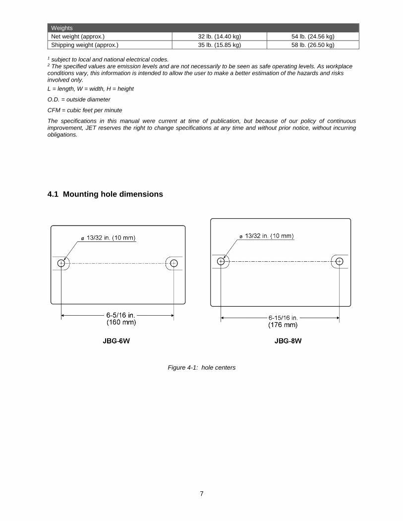
4.1 Mounting hole dimensions
Figure 4-1: hole centers

8
5.0 Setup and assembly
5.1 Unpacking Separate all parts from the packing material. Check each part against sect. 5.2, Carton contents, and make certain that all items are accounted for. (Check grinder first to verify if any parts have been pre-mounted.) Notify your dealer or JET if parts are missing or there is shipping damage. Do not discard packing material until grinder is assembled and operating properly.
5.2 Carton contents Refer to Figure 5-1. 1 Bench Grinder with wheels (not shown) 1 Spark guard, left – A 2 Lock knobs – B 1 Spark guard, right – C 1 Eye shield bracket, left – D 2 Truss head screws, 1/4 x 1/2 – E 1 Eye shield bracket, right – F 2 Eye shield plates – G 4 Hex cap screws, 5/16 x 3/4 – H 4 Flat washers, 5/16 – J 4 Pan head screws, 3/16 x 3/8 – K 4 Hex cap screws 1/4 x 3/8 – L 6 Flat Washers 1/4 – M 2 Lock Washers 1/4 – N 1 Tool rest, left – O 1 Tool rest, right – P 2 Eye shields – R 1 Operating Instructions and Parts Manual 1 Product registration card
5.3 Tools required for assembly 10mm and 12mm, or adjustable, wrench #1 or #2 cross-point (Phillips) screwdriver The JBG-W series Grinder requires only assembly of eye shields and tool rests. Additional tools may be needed for fastening the grinder to a workbench or stand. For your safety, do not plug the grinder into a power source until all assembly and adjustments are complete.
Be sure that grinder is unplugged and power switch is in OFF position. Do not plug in grinder to power until it is inspected for shipping damage and fully assembled. Failure to comply may cause serious injury.
Do not operate grinder without all guards and shields in place and in working order. Failure to comply may cause serious injury.
Chipped or cracked wheels can break up and cause serious damage to grinder and/or severe injury to operator. Regularly inspect wheels for damage.
Figure 5-1: carton contents

9
5.4 Securing the grinder To prevent the grinder from moving during operation, it should be securely mounted to a work surface or grinder stand. Fasteners for mounting are not included with the grinder.
1. Align the mounting holes on grinder with predrilled holes in a bench or grinder stand. Figure 4-1 shows hole centers for mounting.
2. Insert 3/8-in. (or 10mm) bolts through the holes and tighten, using washers and nuts.
An optional pedestal stand (not included) is available from JET for your grinder. See sect. 11.0.
5.5 Assembling eye shield brackets to spark guards
Refer to Figure 5-2.
Note: Spark guards (A/C) and eye shield brackets (D/F) are marked L for left side assembly and R for right side assembly.
1. Assemble left spark guard and eye shield bracket using Figure 5-2 as a guide. Make sure spark guard and bracket are marked L.
2. Assemble right side components in similar manner.
Figure 5-2: bracket to spark guard
5.6 Installing spark guard/bracket Refer to Figure 5-3.
1. Install left spark guard and mounting bracket assembly to left wheel housing with two 1/4" x 3/8” hex cap screws (L) and two 1/4" flat washers (M).
2. The spark guard (A1) should be adjusted to within 1/16" of the grinding wheel surface or other accessory being used. As the wheel
wears down, the spark guard must be re-adjusted to maintain this 1/16" distance.
3. Install right spark guard and mounting bracket in similar manner.
5.7 Eye shield Refer to Figure 5-3.
The eye shields are identical and will fit on either side of grinder.
Insert two 3/16 x 3/8 pan head screws (K) through bracket, eye shield (R), and plate (G) which contains threaded mounting holes. Tighten screws.
5.8 Tool rest Refer to Figure 5-3.
There is a left and a right tool rest. Refer to Figure 5-3 to ensure proper orientation.
1. Install left tool rest (O) by inserting two 5/16 x 3/4 hex cap screws (H) through two 5/16 flat washers (J), and tool rest, into wheel housing.
2. The tool rest should be adjusted to within 1/16" of the grinding wheel or other accessories being used. As the wheel wears down, the tool rest must be readjusted to maintain a maximum 1/16" clearance.
3. Assemble right tool rest in similar manner.
Figure 5-3: guard and tool rest
10
5.9 Dust port It is recommended that a metalworking dust collection system be connected to the grinder’s dust port, using a 2-in. diameter hose with hose clamp (not provided).
6.0 Electrical connections
Electrical connections must be made by a qualified electrician in compliance with all relevant codes. This tool must be properly grounded. Failure to comply may result in serious injury.
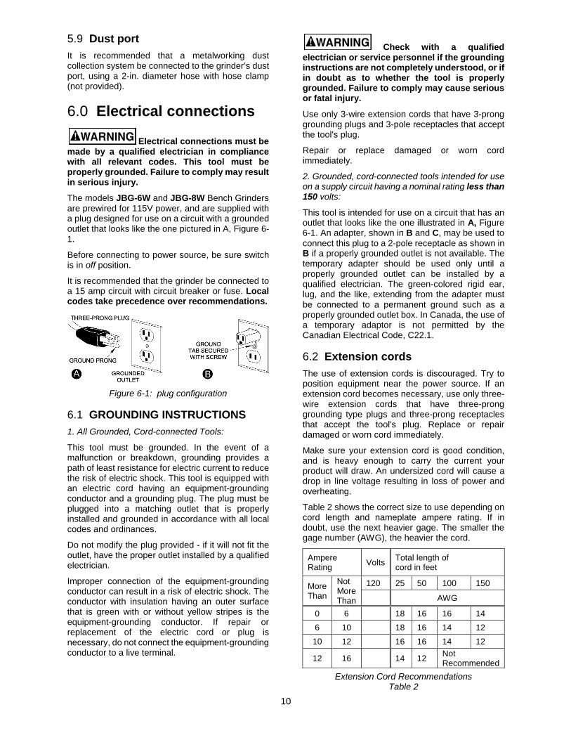
The models JBG-6W and JBG-8W Bench Grinders are prewired for 115V power, and are supplied with a plug designed for use on a circuit with a grounded outlet that looks like the one pictured in A, Figure 6-1.
Before connecting to power source, be sure switch is in off position.
It is recommended that the grinder be connected to a 15 amp circuit with circuit breaker or fuse. Local codes take precedence over recommendations.
Figure 6-1: plug configuration
6.1 GROUNDING INSTRUCTIONS 1. All Grounded, Cord-connected Tools:
This tool must be grounded. In the event of a malfunction or breakdown, grounding provides a path of least resistance for electric current to reduce the risk of electric shock. This tool is equipped with an electric cord having an equipment-grounding conductor and a grounding plug. The plug must be plugged into a matching outlet that is properly installed and grounded in accordance with all local codes and ordinances.
Do not modify the plug provided - if it will not fit the outlet, have the proper outlet installed by a qualified electrician.
Improper connection of the equipment-grounding conductor can result in a risk of electric shock. The conductor with insulation having an outer surface that is green with or without yellow stripes is the equipment-grounding conductor. If repair or replacement of the electric cord or plug is necessary, do not connect the equipment-grounding conductor to a live terminal.
Check with a qualified electrician or service personnel if the grounding instructions are not completely understood, or if in doubt as to whether the tool is properly grounded. Failure to comply may cause serious or fatal injury.
Use only 3-wire extension cords that have 3-prong grounding plugs and 3-pole receptacles that accept the tool's plug.
Repair or replace damaged or worn cord immediately.
2. Grounded, cord-connected tools intended for use on a supply circuit having a nominal rating less than 150 volts:
This tool is intended for use on a circuit that has an outlet that looks like the one illustrated in A, Figure 6-1. An adapter, shown in B and C, may be used to connect this plug to a 2-pole receptacle as shown in B if a properly grounded outlet is not available. The temporary adapter should be used only until a properly grounded outlet can be installed by a qualified electrician. The green-colored rigid ear, lug, and the like, extending from the adapter must be connected to a permanent ground such as a properly grounded outlet box. In Canada, the use of a temporary adaptor is not permitted by the Canadian Electrical Code, C22.1.
6.2 Extension cords The use of extension cords is discouraged. Try to position equipment near the power source. If an extension cord becomes necessary, use only three-wire extension cords that have three-prong grounding type plugs and three-prong receptacles that accept the tool's plug. Replace or repair damaged or worn cord immediately.
Make sure your extension cord is good condition, and is heavy enough to carry the current your product will draw. An undersized cord will cause a drop in line voltage resulting in loss of power and overheating.
Table 2 shows the correct size to use depending on cord length and nameplate ampere rating. If in doubt, use the next heavier gage. The smaller the gage number (AWG), the heavier the cord.
Ampere Rating Volts Total length of
cord in feet
More Than
Not More Than
120 25 50 100 150
AWG
0 6 18 16 16 14 6 10 18 16 14 12
10 12 16 16 14 12
12 16 14 12 Not Recommended
Extension Cord Recommendations Table 2
11
7.0 Operation
Always use approved safety glasses or face shield. Failure to comply may cause serious injury.
A bench grinder is designed for hand-grinding operations such as sharpening chisels, screwdrivers, drill bits, removing excess metal, and smoothing and polishing metal surfaces.
A Medium Grain Abrasive Wheel is suitable for rough grinding where a considerable amount of metal must be removed or when obtaining a smooth finish is not important. A Fine Grain Abrasive Wheel should be used for sharpening tools or grinding to close size tolerances because it removes metal more gradually for precision grinding and gives work a smooth finish.
Wire brushing provides a fast way to remove rust scale, burrs, and point from metal. Use coarse wire brushes for hard cleaning jobs. Use fine wire brushes for polishing and finish work. When brush tips become dull, reverse the brush on the grinder.
7.1 On/Off Switch
When grinder is turned off, the wheel may take a few moments to completely stop.
Press rocker or toggle switch to start and stop grinder.
Note: After extended operation, the grinder housing may be warm to the touch. This is not abnormal.
7.2 Precautions 7.2.1 Wheel grinding
1. Before starting grinder, turn wheels by hand to verify they are clear of obstructions and turn freely. The tool rests and spark guards should not touch the wheel.
2. Keep tool rest and spark guard to within 1/16" of grinding wheel.
3. Turn on grinder and allow it to reach full running speed before starting to grind.
4. Adjust the eye shields as needed.
5. Keep a steady, moderate pressure on the workpiece and keep it moving at an even pace for smooth grinding. Pressing too hard overheats the motor and prematurely wears the grinding wheel. Note the original bevel angle on the item to be sharpened and try to maintain the same shape. The grinding wheel should rotate into the object being sharpened.
6. If grinding a narrow workpiece, slide it laterally across width of wheel. Using full width of wheel
will help prevent a groove from forming at one place on the wheel.
7. Keep a tray filled with water and dip your work into it regularly to prevent overheating. Overheating can weaken metals. Do not apply water directly to a grinding wheel.
8. Do not use the side of the grinding wheel; this puts dangerous stress on the wheel.
9. When wheel becomes loaded or dull, use an approved grinding wheel dresser and dress the wheel face.
8.0 Adjustments
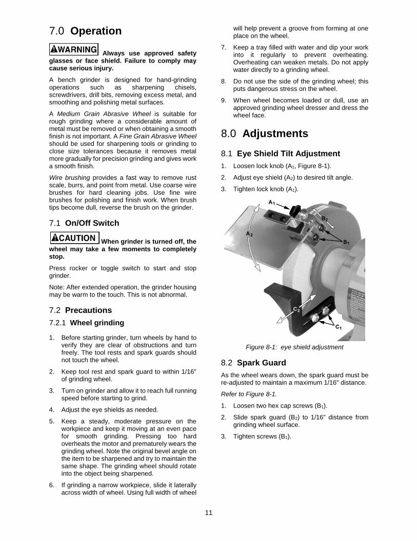
8.1 Eye Shield Tilt Adjustment 1. Loosen lock knob (A1, Figure 8-1).
2. Adjust eye shield (A2) to desired tilt angle.
3. Tighten lock knob (A1).
Figure 8-1: eye shield adjustment
8.2 Spark Guard As the wheel wears down, the spark guard must be re-adjusted to maintain a maximum 1/16" distance.
Refer to Figure 8-1.
1. Loosen two hex cap screws (B1).
2. Slide spark guard (B2) to 1/16" distance from grinding wheel surface.
3. Tighten screws (B1).
12
8.3 Tool Rest As the wheel wears down, the tool rest must be re-adjusted to maintain a maximum 1/16" distance.
Refer to Figure 8-1.
1. Loosen two hex cap screws (C1).
2. Slide tool rest (C2) to within 1/16" from grinding wheel.
3. Tighten screws (C1).
9.0 User-maintenance For safety, turn switch to OFF and remove plug from power source outlet before adjusting or performing maintenance on the bench grinder.
If the power cord is worn, cut or damaged in any way, have it replaced immediately.
9.1 Ring Test Before replacing a grinding wheel, perform this simple test on the replacement wheel:
1. Loop a piece of string through the grinding wheel hole and suspend the wheel by holding up the string.
2. Tap the wheel with a piece of scrap wood or wooden dowel.
3. A good wheel will "ring"; a defective wheel will "thud". Discard any wheel that does not "ring".
An internal defect may not be apparent by visual inspection alone. The ring test may identify an internal crack or void.
9.2 Care of Grinding Wheels In normal use, grinding wheels may become cracked, grooved, rounded at the edges, chipped, out of true or loaded with foreign material.
A cracked wheel should be replaced IMMEDIATELY. The other conditions can be remedied with a dressing tool. New wheels sometimes require dressing to make them round. See sect. 9.5.
9.3 Changing Wheels The JET bench grinder comes equipped with a general purpose grinding wheel. Wheels vary according to types of abrasive, hardness, grit size, and structure. Contact your local distributor for the proper grinding wheel or wire wheel for your application.
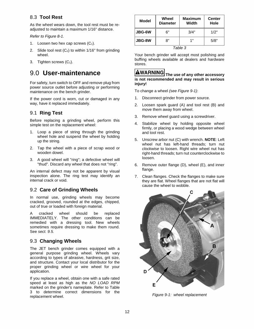
If you replace a wheel, obtain one with a safe rated speed at least as high as the NO LOAD RPM marked on the grinder's nameplate. Refer to Table 3 to determine correct dimensions for the replacement wheel.
Model Wheel Diameter
Maximum Width
Center Hole
JBG-6W 6" 3/4" 1/2"
JBG-8W 8" 1" 5/8"
Table 3
Your bench grinder will accept most polishing and buffing wheels available at dealers and hardware stores.
The use of any other accessory is not recommended and may result in serious injury!
To change a wheel (see Figure 9-1):
1. Disconnect grinder from power source.
2. Loosen spark guard (A) and tool rest (B) and move them away from wheel.
3. Remove wheel guard using a screwdriver.
4. Stabilize wheel by holding opposite wheel firmly, or placing a wood wedge between wheel and tool rest.
5. Unscrew arbor nut (C) with wrench. NOTE: Left wheel nut has left-hand threads; turn nut clockwise to loosen. Right wire wheel nut has right-hand threads; turn nut counterclockwise to loosen.
6. Remove outer flange (D), wheel (E), and inner flange.
7. Clean flanges. Check the flanges to make sure they are flat. Wheel flanges that are not flat will cause the wheel to wobble.
Figure 9-1: wheel replacement
13
8. Inspect the new grinding wheel and perform a “ring test” (sect. 9.1). Do not install a damaged wheel.
9. Install inner flange, wheel (E), outer flange (D) and nut (C) on the shaft. Tighten nut.
Do not overtighten nut; this may cause wheel to crack. Maximum safe torque on nut is 20 lbf•ft (270 kgf•cm).
10. Reinstall guard cover. Adjust spark guard and tool rest to 1/16" clearance from wheel.
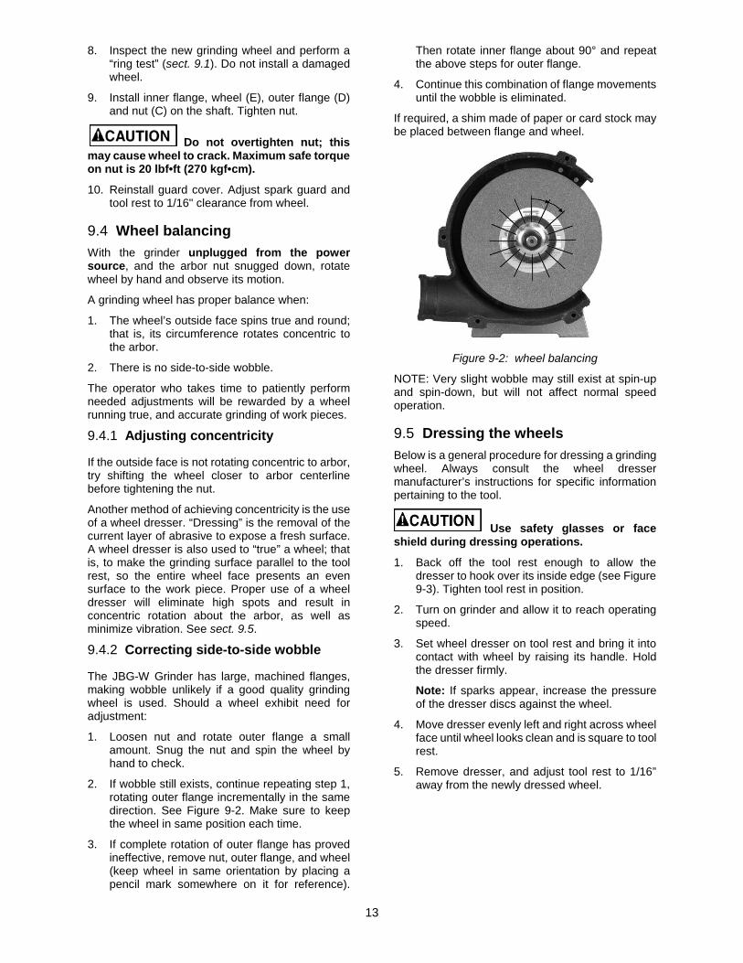
9.4 Wheel balancing With the grinder unplugged from the power source, and the arbor nut snugged down, rotate wheel by hand and observe its motion.
A grinding wheel has proper balance when:
1. The wheel’s outside face spins true and round; that is, its circumference rotates concentric to the arbor.
2. There is no side-to-side wobble.
The operator who takes time to patiently perform needed adjustments will be rewarded by a wheel running true, and accurate grinding of work pieces.
9.4.1 Adjusting concentricity
If the outside face is not rotating concentric to arbor, try shifting the wheel closer to arbor centerline before tightening the nut.
Another method of achieving concentricity is the use of a wheel dresser. “Dressing” is the removal of the current layer of abrasive to expose a fresh surface. A wheel dresser is also used to “true” a wheel; that is, to make the grinding surface parallel to the tool rest, so the entire wheel face presents an even surface to the work piece. Proper use of a wheel dresser will eliminate high spots and result in concentric rotation about the arbor, as well as minimize vibration. See sect. 9.5.
9.4.2 Correcting side-to-side wobble
The JBG-W Grinder has large, machined flanges, making wobble unlikely if a good quality grinding wheel is used. Should a wheel exhibit need for adjustment:
1. Loosen nut and rotate outer flange a small amount. Snug the nut and spin the wheel by hand to check.
2. If wobble still exists, continue repeating step 1, rotating outer flange incrementally in the same direction. See Figure 9-2. Make sure to keep the wheel in same position each time.
3. If complete rotation of outer flange has proved ineffective, remove nut, outer flange, and wheel (keep wheel in same orientation by placing a pencil mark somewhere on it for reference).
Then rotate inner flange about 90° and repeat the above steps for outer flange.
4. Continue this combination of flange movements until the wobble is eliminated.
If required, a shim made of paper or card stock may be placed between flange and wheel.
Figure 9-2: wheel balancing
NOTE: Very slight wobble may still exist at spin-up and spin-down, but will not affect normal speed operation.
9.5 Dressing the wheels Below is a general procedure for dressing a grinding wheel. Always consult the wheel dresser manufacturer’s instructions for specific information pertaining to the tool.
Use safety glasses or face shield during dressing operations.
1. Back off the tool rest enough to allow the dresser to hook over its inside edge (see Figure 9-3). Tighten tool rest in position.
2. Turn on grinder and allow it to reach operating speed.
3. Set wheel dresser on tool rest and bring it into contact with wheel by raising its handle. Hold the dresser firmly.
Note: If sparks appear, increase the pressure of the dresser discs against the wheel.
4. Move dresser evenly left and right across wheel face until wheel looks clean and is square to tool rest.
5. Remove dresser, and adjust tool rest to 1/16” away from the newly dressed wheel.

14
Figure 9-3: wheel dressing
9.6 Cleaning
Metal shavings may still be hot from recent grinding operations. Make sure shavings and debris are cold before cleaning the grinder.
Avoid use of the following cleaning chemicals or solvents: gasoline, carbon tetrachloride, chlorinated solvents, ammonia and household detergents containing ammonia.
Brush all shavings from motor housing, tool rest, and wheel guard. Check grinding wheel for cracks and chips. Replace if damaged.
9.7 Lubrication All motor bearings are permanently lubricated and sealed at the factory and require no additional lubrication.
9.8 Additional servicing Any other servicing should be performed by an authorized service representative.

15
10.0 Troubleshooting JBG-6W, JBG-8W Bench Grinders Table 4
Symptom Possible Cause Correction *
Motor will not start. Not connected to power source. Verify that switch is on and plug is properly inserted into receptacle.
Motor cord cut or abraded. Replace with new cord.
Wheels cannot rotate because of obstruction.
Unplug and turn grinding wheel by hand to ensure free movement. Restart.
Plug on cord is faulty. Replace with new plug.
Low line voltage. Check power line for proper voltage.
Fuse blown or circuit breaker tripped. Re-set. May be too many machines on one line; use dedicated line if needed.
Faulty switch. Replace switch.
Faulty capacitor. Replace capacitor.
Open circuit in motor or loose connection.
Inspect all lead connections on motor for loose or open connections.
Motor fault. Contact JET technical service.
Motor will not start; fuses blow or circuit breakers trip.
Too many machines running on same circuit.
Turn off other machines and try again. Use dedicated circuit if needed.
Incorrect fuse. Try time delay fuse, or go to circuit with higher rated fuse or circuit breaker.
Wheels cannot rotate because of obstruction.
Unplug and turn grinding wheel by hand to ensure free movement. Clear any obstructions and restart.
Undersized extension cord. Use correct size extension cord.
Short circuit in line cord or plug. Inspect cord or plug for damaged insulation and shorted wires.
Short circuit in motor or loose connections.
Inspect all connections on motor for loose or shorted terminals or worn insulation.
Motor fails to develop full power.
Low line voltage. Check power line for proper voltage.
Capacitor or motor failure. Contact JET technical service.
Motor overheats. Motor overloaded. Reduce pressure against wheel. Make sure grit size is appropriate for the job.
Poor motor ventilation. Unplug and clean out around motor; provide better air circulation.
Capacitor or motor failure. Contact JET technical service.
Motor stalls, resulting in blown fuses or tripped circuit.
Motor overloaded. Reduce load on motor; do not press so hard when grinding.
Capacitor or motor failure. Contact JET technical service.
Short circuit in motor or loose connections.
Inspect connections on motor for loose or shorted terminals or worn insulation.
Low voltage. Correct low voltage conditions.
Incorrect fuses or circuit breakers in power line.
Install correct fuses or circuit breakers.
Motor slows. Motor overloaded. Reduce load on motor; do not press so hard when grinding.
Low line voltage. Check power line for proper voltage.
Loose connections. Inspect and remedy.

16
Symptom Possible Cause Correction *Frequent fuse or circuit breaker failure.
Motor overload. Reduce load on motor; do not press so hard when grinding.
Electrical circuit overload; too many machines running on same circuit.
Turn off other machines and try again. Use dedicated circuit if needed.
Incorrect fuse or circuit breaker. Have electrician upgrade service to outlet.
Excessive vibration. Wheel(s) out of balance; wobbling or not rotating concentric to arbor.
Dress wheel or replace it. Adjust wheel imbalance according to instructions in this manual.
Improper mounting. Secure grinder firmly to bench or stand.
* WARNING: Some corrections may required a qualified electrician.
17
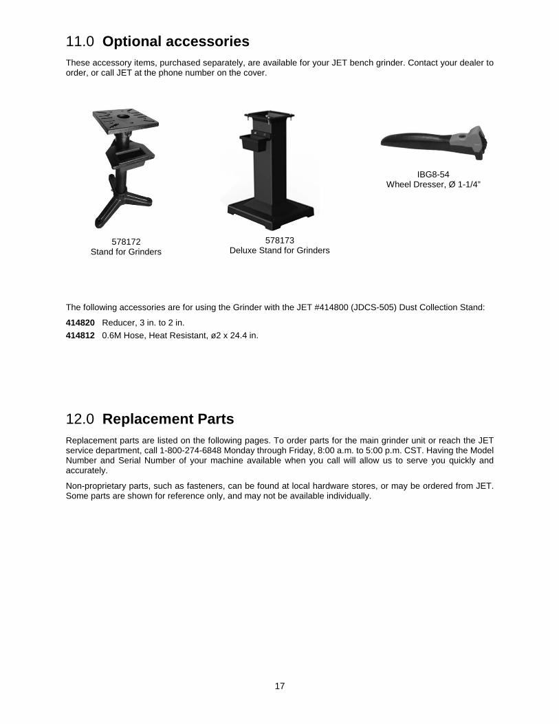
11.0 Optional accessories These accessory items, purchased separately, are available for your JET bench grinder. Contact your dealer to order, or call JET at the phone number on the cover.
578172
Stand for Grinders
578173
Deluxe Stand for Grinders
IBG8-54 Wheel Dresser, Ø 1-1/4”
The following accessories are for using the Grinder with the JET #414800 (JDCS-505) Dust Collection Stand:
414820 Reducer, 3 in. to 2 in. 414812 0.6M Hose, Heat Resistant, ø2 x 24.4 in.
12.0 Replacement Parts Replacement parts are listed on the following pages. To order parts for the main grinder unit or reach the JET service department, call 1-800-274-6848 Monday through Friday, 8:00 a.m. to 5:00 p.m. CST. Having the Model Number and Serial Number of your machine available when you call will allow us to serve you quickly and accurately.
Non-proprietary parts, such as fasteners, can be found at local hardware stores, or may be ordered from JET. Some parts are shown for reference only, and may not be available individually.
18
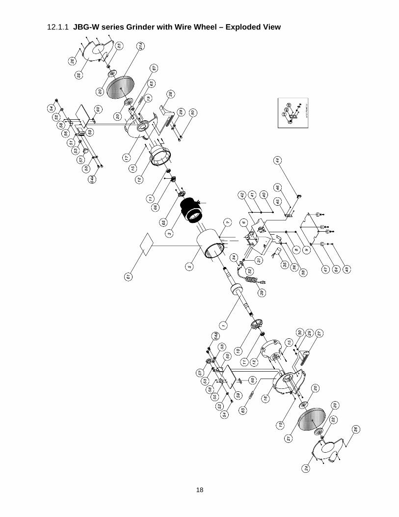
12.1.1 JBG-W series Grinder with Wire Wheel – Exploded View
19
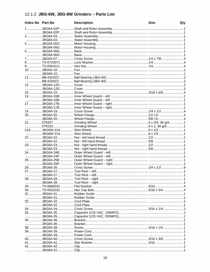
12.1.2 JBG-6W, JBG-8W Grinders – Parts List
Index No Part No Description Size Qty 1 ................ JBG6A-02P ............... Shaft and Rotor Assembly ....................................... ...................................... 1 .................. JBG8A-02P ............... Shaft and Rotor Assembly ....................................... ...................................... 1 3 ................ JBG6A-03 .................. Stator Assembly....................................................... ...................................... 1 .................. JBG8A-03 .................. Stator Assembly....................................................... ...................................... 1 5 ................ JBG6A-05G ............... Motor Housing ......................................................... ...................................... 1 .................. JBG8A-05G ............... Motor Housing ......................................................... ...................................... 1 6 ................ JBG6A-06G ............... Base......................................................................... ...................................... 1 .................. JBG8A-06G ............... Base......................................................................... ...................................... 1 7 ................ JBG6A-07 .................. Cross Screw ........................................................... 1/4 x 7/8 ........................ 4 8 ................ TS-0720071 .............. Lock Washer ............................................................ 1/4 ................................. 4 9 ................ TS-0561011 .............. Hex Nut .................................................................... 1/4 ................................. 4 10 .............. JBG6A-10 .................. Fan........................................................................... ...................................... 1 .................. JBG8A-10 .................. Fan........................................................................... ...................................... 1 11 .............. BB-6202ZZ ................ Ball Bearing (JBG-6A) ............................................. ...................................... 2 .................. BB-6204ZZ ................ Ball Bearing (JBG-8A) ............................................. ...................................... 2 12 .............. JBG6A-12G ............... Cover ....................................................................... ...................................... 2 .................. JBG8A-12G ............... Cover ....................................................................... ...................................... 2 15 .............. JBG6A-15 .................. Screw ....................................................................... 3/16 x 5/8. ..................... 4 16 .............. JBG6A-16B ............... Inner Wheel Guard – left ......................................... ...................................... 1 .................. JBG8A-16B ............... Inner Wheel Guard – left ......................................... ...................................... 1 17 .............. JBG6A-17B ............... Inner Wheel Guard – right ....................................... ...................................... 1 .................. JBG8A-17B ............... Inner Wheel Guard – right ....................................... ...................................... 1 19 .............. JBG6A-19 .................. Cross Screw ............................................................ 1/4 x 1/2 ........................ 4 20 .............. JBG6A-20 .................. Wheel Flange........................................................... 1/2 I.D ........................... 4 .................. JBG8A-20 .................. Wheel Flange........................................................... 5/8 I.D ........................... 4 21 .............. 576207 ...................... Grinding Wheel ........................................................ 6 x 3/4, 36 grit ............... 1 .................. 576223 ...................... Grinding Wheel ........................................................ 8 x 1, 36 grit .................. 1 21A ............ JBG6W-21A .............. Wire Wheel .............................................................. 6 x 1/2 ........................... 1 .................. JBG8W-21A .............. Wire Wheel .............................................................. 8 x 1/2 ........................... 1 22 .............. JBG6A-22 .................. Nut - left hand thread ............................................... 1/2 ................................. 1 .................. JBG8A-22 .................. Nut - left hand thread ............................................... 5/8 ................................. 1 23 .............. JBG6A-23 .................. Nut - right hand thread ............................................. 1/2 ................................. 1 .................. JBG8A-23 .................. Nut - right hand thread ............................................. 5/8 ................................. 1 24 .............. JBG6A-24B ............... Outer Wheel Guard – left ......................................... ...................................... 1 .................. JBG8A-24P ............... Outer Wheel Guard – left ......................................... ...................................... 1 25 .............. JBG6A-25B ............... Outer Wheel Guard – right ...................................... ...................................... 1 .................. JBG8A-25P ............... Outer Wheel Guard – right ...................................... ...................................... 1 26 .............. JBG6A-26 .................. Cross Screw ............................................................ 1/4 x 1/2 ........................ 8 27 .............. JBG6A-27 .................. Tool Rest – left......................................................... ...................................... 1 .................. JBG8A-27 .................. Tool Rest – left......................................................... ...................................... 1 28 .............. JBG6A-28 .................. Tool Rest – right ...................................................... ...................................... 1 .................. JBG8A-28 .................. Tool Rest – right ...................................................... ...................................... 1 29 .............. TS-0680031 .............. Flat Washer ............................................................. 5/16 ............................... 4 30 .............. TS-0051031 .............. Hex Cap Bolt............................................................ 5/16 x 3/4 ...................... 4 31 .............. JBG6A-31 .................. Rubber Guide .......................................................... ...................................... 1 .................. JBG8A-31 .................. Rubber Guide .......................................................... ...................................... 1 32 .............. JBG6A-32 .................. Cord Plate ................................................................ ...................................... 1 .................. JBG8A-32 .................. Cord Plate ................................................................ ...................................... 1 34 .............. JBG6A-34 .................. Cross Screw ............................................................ 3/16 x 1/4 ...................... 2 35 .............. JBG6A-35 .................. Capacitor (125 VAC, 100MFD) ................................ ...................................... 1 .................. JBG8A-35 .................. Capacitor (125 VAC, 200MFD) ................................ ...................................... 1 36 .............. JBG6A-36 .................. Bracket..................................................................... ...................................... 1 .................. JBG8A-36 .................. Bracket..................................................................... ...................................... 1 38 .............. JBG6A-38 .................. Screw ....................................................................... 3/16 x 1/4 ...................... 1 39 .............. JBG6A-39 .................. Power Cord .............................................................. ...................................... 1 .................. JBG8A-39 .................. Power Cord .............................................................. ...................................... 1 40 .............. JBG6A-40 .................. Cross Screw ............................................................ 3/16 x 3/8 ...................... 1 41 .............. JBG6A-41 .................. Star Washer ............................................................. 3/16 ............................... 1 42 .............. JBG6A-42 .................. Clip........................................................................... ...................................... 1 .................. JBG8A-42 .................. Clip........................................................................... ...................................... 1

20
Index No Part No Description Size Qty 44 .............. JBG6A-44 .................. Rocker Switch .......................................................... ...................................... 1 .................. JBG8A-44 .................. Toggle Switch .......................................................... ...................................... 1 45 .............. JBG6A-45 .................. Switch Plate ............................................................. ...................................... 1 .................. JBG8A-45 .................. Switch Plate ............................................................. ...................................... 1 46 .............. JBG6A-46 .................. Screw ....................................................................... 3/16 x 1/4 ...................... 2 47 .............. JBG6A-47 .................. Base Plate ............................................................... ...................................... 1 .................. JBG8A-47 .................. Base Plate ............................................................... ...................................... 1 49 .............. JBG6A-49 .................. Cross Screw ............................................................ 3/16 x 1/2 ...................... 4 .................. JBG8A-49 .................. Cross Screw ............................................................ 3/16 x 1/2 ...................... 4 50 .............. JBG8A-50 .................. Spark Guard – left ................................................... ...................................... 1 51 .............. JBG8A-51 .................. Spark Guard – right ................................................. ...................................... 1 52 .............. TS-0720071 .............. Lock Washer ............................................................ 1/4 ................................. 2 53 .............. TS-0680021 .............. Flat Washer ............................................................. 1/4 ................................. 6 54 .............. JBG6A-54 .................. Cross Screw ............................................................ 1/4 x 1/2 ........................ 2 54A ............ JBG6A-54 .................. Cross Screw ............................................................ 1/4 x 3/8 ........................ 4 55 .............. JBG8A-55 .................. Eye Shield Bracket – left ......................................... ...................................... 1 56 .............. JBG8A-56 .................. Eye Shield Bracket – right. ...................................... ...................................... 1 57 .............. JBG6A-57 .................. Lock Knob ................................................................ 1/4 ................................. 2 58 .............. JBG6A-58 .................. Cross Screw ............................................................ 3/16 x 3/8 ...................... 4 59 ............. JBG8A-59 .................. Eye Shield .............................................................. ...................................... 2 .................. JBG8A-59A ............... Eye Shield Assembly (includes #50 thru 60, LH and RH sets) ....................... 1 60 .............. JBG8A-60 .................. Eye Shield Plate ...................................................... ...................................... 2 61 .............. LM000335 ................. Identification Label, JBG-6W ................................... ...................................... 1 .................. LM000336 ................. Identification Label, JBG-8W ................................... ...................................... 1 63 .............. JBG6A-63 .................. Direction Label ......................................................... ...................................... 2 64 .............. JBG6A-64 .................. Rubber Foot ............................................................. ...................................... 4 65 .............. JBG6A-65 .................. Switch Seat .............................................................. ...................................... 1 .................. JBG8A-65 .................. Switch Seat .............................................................. ...................................... 1 66 .............. JBG6A-66 .................. Centrifugal Start Switch ........................................... ...................................... 1 .................. JBG8A-66 .................. Centrifugal Start Switch ........................................... ...................................... 1 67 .............. JBG6W-67 ................. Bushing .................................................................... ...................................... 1 .................. JBG8W-67 ................. Bushing .................................................................... ...................................... 1

21
13.0 Wiring Diagram for JBG-6W, JBG-8W Grinders

22
14.0 Warranty and service JET® warrants every product it sells against manufacturers’ defects. If one of our tools needs service or repair, please contact Technical Service by calling 1-800-274-6846, 8AM to 5PM CST, Monday through Friday.
Warranty Period The general warranty lasts for the time period specified in the literature included with your product or on the official JET branded website.
• JET products carry a limited warranty which varies in duration based upon the product. (See chart below) • Accessories carry a limited warranty of one year from the date of receipt. • Consumable items are defined as expendable parts or accessories expected to become inoperable within a
reasonable amount of use and are covered by a 90 day limited warranty against manufacturer’s defects.
Who is Covered This warranty covers only the initial purchaser of the product from the date of delivery.
What is Covered This warranty covers any defects in workmanship or materials subject to the limitations stated below. This warranty does not cover failures due directly or indirectly to misuse, abuse, negligence or accidents, normal wear-and-tear, improper repair, alterations or lack of maintenance. JET woodworking machinery is designed to be used with Wood. Use of these machines in the processing of metal, plastics, or other materials outside recommended guidelines may void the warranty. The exceptions are acrylics and other natural items that are made specifically for wood turning.
Warranty Limitations Woodworking products with a Five Year Warranty that are used for commercial or industrial purposes default to a Two Year Warranty. Please contact Technical Service at 1-800-274-6846 for further clarification.
How to Get Technical Support Please contact Technical Service by calling 1-800-274-6846. Please note that you will be asked to provide proof of initial purchase when calling. If a product requires further inspection, the Technical Service representative will explain and assist with any additional action needed. JET has Authorized Service Centers located throughout the United States. For the name of an Authorized Service Center in your area call 1-800-274-6846 or use the Service Center Locator on the JET website.
More Information JET is constantly adding new products. For complete, up-to-date product information, check with your local distributor or visit the JET website.
How State Law Applies This warranty gives you specific legal rights, subject to applicable state law.
Limitations on This Warranty JET LIMITS ALL IMPLIED WARRANTIES TO THE PERIOD OF THE LIMITED WARRANTY FOR EACH PRODUCT. EXCEPT AS STATED HEREIN, ANY IMPLIED WARRANTIES OF MERCHANTABILITY AND FITNESS FOR A PARTICULAR PURPOSE ARE EXCLUDED. SOME STATES DO NOT ALLOW LIMITATIONS ON HOW LONG AN IMPLIED WARRANTY LASTS, SO THE ABOVE LIMITATION MAY NOT APPLY TO YOU. JET SHALL IN NO EVENT BE LIABLE FOR DEATH, INJURIES TO PERSONS OR PROPERTY, OR FOR INCIDENTAL, CONTINGENT, SPECIAL, OR CONSEQUENTIAL DAMAGES ARISING FROM THE USE OF OUR PRODUCTS. SOME STATES DO NOT ALLOW THE EXCLUSION OR LIMITATION OF INCIDENTAL OR CONSEQUENTIAL DAMAGES, SO THE ABOVE LIMITATION OR EXCLUSION MAY NOT APPLY TO YOU. JET sells through distributors only. The specifications listed in JET printed materials and on official JET website are given as general information and are not binding. JET reserves the right to effect at any time, without prior notice, those alterations to parts, fittings, and accessory equipment which they may deem necessary for any reason whatsoever. JET® branded products are not sold in Canada by JPW Industries, Inc.
Product Listing with Warranty Period 90 Days – Parts; Consumable items 1 Year – Motors; Machine Accessories 2 Year – Metalworking Machinery; Electric Hoists, Electric Hoist Accessories; Woodworking Machinery used for industrial or commercial purposes 5 Year – Woodworking Machinery Limited Lifetime – JET Parallel clamps; VOLT Series Electric Hoists; Manual Hoists; Manual Hoist Accessories; Shop Tools; Warehouse & Dock products; Hand Tools; Air Tools
NOTE: JET is a division of JPW Industries, Inc. References in this document to JET also apply to JPW Industries, Inc., or any of its successors in interest to the JET brand.

23

24
427 New Sanford Road LaVergne, Tennessee 37086
Phone: 800-274-6848 www.jettools.com