Operating Instructions and Parts Manual 15-inch Planer-Molder
40
Operating Instructions and Parts Manual 15-inch Planer-Molder Model PM15 For machines with serial number 0412PM15488 and higher WALTER MEIER (Manufacturing) Inc. 427 New Sanford Rd. LaVergne, TN 37086 Part No. M-0460264 Ph.: 800-274-6848 Revision F2 11/2010 www.powermatic.com Copyright © 2010 Walter Meier (Manufacturing) Inc.
Transcript of Operating Instructions and Parts Manual 15-inch Planer-Molder

Operating Instructions and Parts Manual 15-inch Planer-Molder Model PM15
For machines with serial number 0412PM15488 and higher
WALTER MEIER (Manufacturing) Inc. 427 New Sanford Rd. LaVergne, TN 37086 Part No. M-0460264 Ph.: 800-274-6848 Revision F2 11/2010 www.powermatic.com Copyright © 2010 Walter Meier (Manufacturing) Inc.
Tom Gauger
This .pdf document is bookmarked

2
Warranty and Service Walter Meier (Manufacturing) Inc., warrants every product it sells. If one of our tools needs service or repair, one of our Authorized Service Centers located throughout the United States can give you quick service. In most cases, any of these Walter Meier Authorized Service Centers can authorize warranty repair, assist you in obtaining parts, or perform routine maintenance and major repair on your POWERMATIC® tools. For the name of an Authorized Service Center in your area call 1-800-274-6848. MORE INFORMATION Walter Meier is consistently adding new products to the line. For complete, up-to-date product information, check with your local Walter Meier distributor, or visit powermatic.com. WARRANTY POWERMATIC products carry a limited warranty which varies in duration based upon the product.
WHAT IS COVERED? This warranty covers any defects in workmanship or materials subject to the exceptions stated below. Cutting tools, abrasives and other consumables are excluded from warranty coverage. WHO IS COVERED? This warranty covers only the initial purchaser of the product. WHAT IS THE PERIOD OF COVERAGE? The general POWERMATIC warranty lasts for the time period specif ied in the product literature of each product. WHAT IS NOT COVERED? The Five Year Warranty does not cover products used for commercial, industrial or educational purposes. Products with a Five Year Warranty that are used for commercial, industrial or education purposes revert to a One Year Warranty. This warranty does not cover defects due directly or indirectly to misuse, abuse, negligence or accidents, normal wear-and-tear, improper repair or alterations, or lack of maintenance. HOW TO GET SERVICE The product or part must be returned for examination, postage prepaid, to a location designated by us. For the name of the location nearest you, please call 1-800-274-6848. You must provide proof of initial purchase date and an explanation of the complaint must accompany the merchandise. If our inspection discloses a defect, we will repair or replace the product, or refund the purchase price, at our option. We will return the repaired product or replacement at our expense unless it is determined by us that there is no defect, or that the defect resulted from causes not within the scope of our warranty in which case we will, at your direction, dispose of or return the product. In the event you choose to have the product returned, you will be responsible for the handling and shipping costs of the return. HOW STATE LAW APPLIES This warranty gives you specific legal rights; you may also have other rights which vary from state to state. LIMITATIONS ON THIS WARRANTY WALTER MEIER (MANUFACTURING) INC., LIMITS ALL IMPLIED WARRANTIES TO THE PERIOD OF THE LIMITED WARRANTY FOR EACH PRODUCT. EXCEPT AS STATED HEREIN, ANY IMPLIED WARRANTIES OR MERCHANTABILITY AND FITNESS ARE EXCLUDED. SOME STATES DO NOT ALLOW LIMITATIONS ON HOW LONG THE IMPLIED WARRANTY LASTS, SO THE ABOVE LIMITATION MAY NOT APPLY TO YOU. WALTER MEIER SHALL IN NO EVENT BE LIABLE FOR DEATH, INJURIES TO PERSONS OR PROPERTY, OR FOR INCIDENTAL, CONTINGENT, SPECIAL, OR CONSEQUENTIAL DAMAGES ARISING FROM THE USE OF OUR PRODUCTS. SOME STATES DO NOT ALLOW THE EXCLUSION OR LIMITATION OF INCIDENTAL OR CONSEQUENTIAL DAMAGES, SO THE ABOVE LIMITATION OR EXCLUSION MAY NOT APPLY TO YOU. Walter Meier sells through distributors only. The specifications in Walter Meier catalogs are given as general information and are not binding. Members of Walter Meier reserve the right to effect at any time, without prior notice, those alterations to parts, fittings, and accessory equipment which they may deem necessary for any reason whatsoever.

3
Table of Contents Warranty and Service..........................................................................................................................2 Table of Contents ...............................................................................................................................3 Warning .............................................................................................................................................4 Introduction ........................................................................................................................................6 Specifications .....................................................................................................................................6 Unpacking ..........................................................................................................................................7
Contents of the Shipping Container ..................................................................................................7 Installation and Assembly ....................................................................................................................7
Installing Dust Chute .......................................................................................................................8 Installing Handwheel .......................................................................................................................8
Electrical Connections.........................................................................................................................8 Extension Cords ..............................................................................................................................9
Adjustments .......................................................................................................................................9 Belt Tension ....................................................................................................................................9 Planer Knife Replacement................................................................................................................9 Sharpening Knives ........................................................................................................................ 10 Depth of Cut.................................................................................................................................. 11 Feed Rate ..................................................................................................................................... 11 The Planer’s Feed System ............................................................................................................. 11 Leveling Cutterhead with Bed ......................................................................................................... 14 Interlock Switch ............................................................................................................................. 15 Caster Lock .................................................................................................................................. 15
Operation ......................................................................................................................................... 15 Kinds of Warp ............................................................................................................................... 15 Planing to Desired Thickness ......................................................................................................... 16 Depth of Cut.................................................................................................................................. 16 Thickness Planing Steps ................................................................................................................ 16 Planing for Finish .......................................................................................................................... 17
Introduction to Molding ...................................................................................................................... 17 Pattern Knives............................................................................................................................... 17 Optional Bedboard and Guide ........................................................................................................ 17 Homemade Bedboard.................................................................................................................... 18 Homemade Featherboard .............................................................................................................. 18 Homemade Guide Set-Up for Edge Molding .................................................................................... 18 Installing Single Pattern Knives ...................................................................................................... 18 Installing Three-Knife Set ............................................................................................................... 19 Pattern Knife Clearance ................................................................................................................. 19 Installing Bedboard ........................................................................................................................ 20 Face Molding with pattern knives .................................................................................................... 20 Edge Molding with pattern knives ................................................................................................... 21 Edge Planing ................................................................................................................................ 21 Common Molding Applications ....................................................................................................... 21
Maintenance .................................................................................................................................... 23 Lubrication .................................................................................................................................... 23
Replacement Parts ........................................................................................................................... 28 Parts List: Base Assembly.............................................................................................................. 29 Base Assembly ............................................................................................................................. 30 Parts List: Gearbox Assembly ........................................................................................................ 31 Gearbox Assembly ........................................................................................................................ 32 Parts List: Stand Assembly ............................................................................................................ 33 Stand Assembly ............................................................................................................................ 34 Parts List: Cutterhead, Hood and Table Assembly ........................................................................... 35 Cutterhead, Hood and Table Assembly ........................................................................................... 37
Electrical Connections....................................................................................................................... 38

4
Warning
1. Read and understand the entire owner’s manual before attempting assembly or operation.
2. Read and understand the warnings posted on the machine and in this manual. Failure to comply with all of these warnings may cause serious injury.
3. Replace the warning labels if they become obscured or removed.
4. This planer-molder is designed and intended for use by properly trained and experienced personnel only. If you are not familiar with the proper and safe operation of a planer-molder, do not use until proper training and knowledge have been obtained.
5. Do not use this planer-molder for other than its intended use. If used for other purposes, Walter Meier (Manufacturing) Inc. disclaims any real or implied warranty and holds itself harmless from any injury that may result from that use.
6. Always wear approved safety glasses/face shields while using this machine. Everyday eyeglasses only have impact resistant lenses; they are not safety glasses.
7. Before operating this planer-molder, remove tie, rings, watches and other jewelry, and roll sleeves up past the elbows. Remove all loose clothing and confine long hair. Non-slip footwear or anti-skid floor strips are recommended. Do not wear gloves.
8. Wear ear protectors (plugs or muffs) during extended periods of operation.
9. Some dust created by power sanding, sawing, grinding, drilling and other construction activities contains chemicals known to cause cancer, birth defects or other reproductive harm. Some examples of these chemicals are:
• Lead from lead based paint. • Crystalline silica from bricks, cement and other masonry products. • Arsenic and chromium from chemically treated lumber.
Your risk of exposure varies, depending on how often you do this type of work. To reduce your exposure to these chemicals, work in a well-ventilated area and work with approved safety equipment, such as face or dust masks that are specifically designed to filter out microscopic particles.
10. Do not operate this machine while tired or under the influence of drugs, alcohol or any medication.
11. Make certain the switch is in the OFF position before connecting the machine to the power supply.
12. Make certain the machine is properly grounded.
13. Make all machine adjustments or maintenance with the machine unplugged from the power source.
14. Remove adjusting keys and wrenches. Form a habit of checking to see that keys and adjusting wrenches are removed from the machine before turning it on.
15. Keep safety guards in place at all times when the machine is in use. If removed for maintenance purposes, use extreme caution and replace the guards immediately.
16. Make sure the casters are locked before operating the planer-molder.
17. Check damaged parts. Before further use of the machine, a guard or other part that is damaged should be carefully checked to determine that it will operate properly and perform its intended function. Check for alignment of moving parts, binding of moving parts, breakage of parts, mounting and any other conditions that may affect its operation. A guard or other part that is damaged should be properly repaired or replaced.
18. Provide for adequate space surrounding work area and non-glare, overhead lighting.
19. Keep the floor around the machine clean and free of scrap material, oil and grease.
20. Keep visitors a safe distance from the work area. Keep children away.

5
21. Make your workshop child proof with padlocks, master switches or by removing starter keys.
22. Give your work undivided attention. Looking around, carrying on a conversation and “horse-play” are careless acts that can result in serious injury.
23. Maintain a balanced stance at all times so that you do not fall or lean against the knives or other moving parts. Do not overreach or use excessive force to perform any machine operation.
24. Use the right tool at the correct speed and feed rate. Do not force a tool or attachment to do a job for which it was not designed. The right tool will do the job better and safer.
25. Use recommended accessories; improper accessories may be hazardous.
26. When using a molding knife, use only the particular gibs and counterweights supplied with that knife.
27. Maintain tools with care. Keep knives sharp and clean for the best and safest performance. Follow instructions for lubricating and changing accessories.
28. Turn off the machine and disconnect from power before cleaning. Use a brush or compressed air to remove chips or debris — do not use your hands.
29. Do not stand on the machine. Serious injury could occur if the machine tips over.
30. Never leave the machine running unattended. Turn the power off and do not leave the machine until it comes to a complete stop.
31. Remove loose items and unnecessary work pieces from the area before starting the machine.
Familiarize yourself with the following safety notices used in this manual:
This means that if precautions are not heeded, it may result in minor injury and/or possible machine damage.
This means that if precautions are not heeded, it may result in serious injury or possibly even death.
- - SAVE THESE INSTRUCTIONS - -

6
Introduction This manual is provided by Walter Meier (Manufacturing) Inc. covering the safe operation and maintenance procedures for a Powermatic Model PM15 Planer-Molder. This manual contains instructions on installation, safety precautions, general operating procedures, maintenance instructions and parts breakdown. This machine has been designed and constructed to provide years of trouble free operation if used in accordance with instructions set forth in this manual. If there are any questions or comments, please contact either your local supplier or Walter Meier. Walter Meier can also be reached at our web site: www.waltermeier.com.
Specifications Model Number ............................................................................................................................. PM15 Stock Number .........................................................................................................................1120003 Table overall size (in.) .................................................................................................... 27-1/2 x 15-1/8 Table Height Adjustment (in.) ............................................................................................1 Turn = 1/16 Maximum cutting width (in.) ............................................................................................................... 15 Maximum thickness (in.)................................................................................................................ 6-1/2 Minimum thickness (in.).................................................................................................................. 3/16 Maximum depth of cut – Planing (in.) ................................................................................................ 1/8 Maximum depth of cut – Molding (in.) ................................................................................................ 3/4 Minimum workpiece length (in.) ........................................................................................................... 8 Number of planing knives .................................................................................................................... 3 Urethane feed rollers diameter (in.) ................................................................................................ 1-1/2 Cutterhead speed (RPM)............................................................................................................... 4500 Cuts per minute ......................................................................................................................... 13,500 Cutterhead diameter (in.)............................................................... 2-7/8 (3” with planing knives installed) Feed rates (FPM) .................................................................................................................. 10 and 20 Dust Port Diameter (in.)....................................................................................................................... 4 Dust Collection Minimum CFM Required .......................................................................................... 900 Overall dimensions (LxWxH)(in.)......................................................................................... 28 x 34 x 51 Motor ............................................................................................... TEFC, 5HP, 1PH, 230V only, 60Hz Net Weight (lbs.) ............................................................................................................................. 423 Shipping weight (lbs.) ...................................................................................................................... 550
The above specifications were current at the time this manual was published, but because of our policy of continuous improvement, Walter Meier reserves the right to change specifications at any time and without prior notice, without incurring obligations.

7
Unpacking Open shipping container and check for shipping damage. Report any damage immediately to your distributor and shipping agent. Do not discard any shipping material until the Planer/Molder is assembled and running properly.
Compare the contents of your container with the following parts list to make sure all parts are intact. Missing parts, if any, should be reported to your distributor. Read the instruction manual thoroughly for assembly, maintenance and safety instructions.
Contents of the Shipping Container Refer to Figure 1. 1 Planer/Molder (not shown) 1 Dust Chute – A 1 Dust Hood – B 1 Straight Knife Setting Gauge Assy. – C 1 Handwheel – D 1 Handle – E 3 Knife Gibs – F 8 Phillips Pan Head Screws, M6x12 – G 8 Flat Washers, M6 – H 1 Socket Head Cap Screw, M6 x 15 - J 1 Lock Washer, M6 – K 1 Flat Washer, M6 – L 1 Reversible Screwdriver – M 1 Brass Punch – N 2 T-Handle Hex Wrenches (4,6 mm) – O 1 Hex Wrench Set (3,4,5,6 mm) – P 1 Open-End Wrench 10-12mm – R 1 Spanner Wrench – S 1 Molding Knife Gauge – T 1 Owner's Manual (not shown) 1 Warranty Card (not shown) Items E through S comprise hardware package, stock no. PM15-HP.
Installation and Assembly Tools required:
10, 11 and 13mm wrenches
Remove the screws holding the base of the machine to the skid, and lift the planer/molder off the skid.
The machine area should be clean, dry, well ventilated, and well lighted. Since planers can create noise problems, the site selection should be one which minimizes reverberant sound from walls, ceilings and other equipment. The machine’s wheels should be in the locked position prior to use.
Figure 1

8
Electricals should be installed so that they are protected from damage and exposure. Be sure to properly ground the machine frame.
Exposed metal parts, such as the bed surface, have been given a protective coating at the factory. This should be removed with a soft rag and kerosene or a good commercial solvent. Do not use an abrasive pad.
Installing Dust Chute Mount the dust chute with the washer head screws, using a 10mm wrench. See Figure 2.
Installing Handwheel Mount the handwheel by fitting the notches in the handwheel over the pins on the shaft. See Figure 3.
Electrical Connections Electrical connections must
be made by a qualified electrician in compliance with all relevant codes. This machine must be properly grounded to help prevent electrical shock and possible fatal injury.
This machine must be grounded. In the event of a malfunction or breakdown, grounding provides a path of least resistance for electric current to reduce the risk of electric shock.
Improper connection of the equipment-grounding conductor can result in a risk of electric shock. The conductor with insulation having an outer surface that is green with or without yellow stripes, is the equipment-grounding conductor. If repair or replacement of the electric cord or plug is necessary, do not connect the equipment-grounding conductor to a live terminal.
Check with a qualified electrician or service personnel if the grounding instructions are not completely understood, or if in doubt as to whether the tool is properly grounded. Repair or replace a damaged or worn cord immediately.
Make sure the voltage of your power supply matches the specifications on the motor plate of the planer-molder.
It is recommended that the PM15 Planer-Molder be connected to a grounded and dedicated, minimum 60 amp circuit with a 60 amp circuit breaker or time delay fuse. Local codes take precedence over recommendations.
Figure 2
Figure 3
Recommended Gauges (AWG) of Extension Cords
Amps
Extension Cord Length *
25 feet
50 feet
75 feet
100 feet
150 feet
200 feet
< 5 16 16 16 14 12 12
5 to 8 16 16 14 12 10 NR
8 to 12 14 14 12 10 NR NR
12 to 15 12 12 10 10 NR NR
15 to 20 10 10 10 NR NR NR
21 to 30 10 NR NR NR NR NR
*based on limiting the line voltage drop to 5V at 150% of the rated amperes. NR: Not Recommended.
Figure 4

9
Extension Cords If an extension cord is necessary, make sure the cord rating is suitable for the amperage listed on the machine’s motor plate. An under sized cord will cause a drop in line voltage resulting in loss of power and overheating.
Use the chart in Figure 4 as a general guide in choosing the correct size cord. If in doubt, use the next heavier gauge. The smaller the gauge number, the heavier the cord.
Adjustments Tools required: hex wrench 12mm & 14mm wrenches
Disconnect machine from power source before making adjustments.
Belt Tension To adjust tension of the belts, open the rear panel and use the nuts (A) on the threaded shaft, shown in Figure 4, to either raise or lower the motor. Re-tighten nuts when satisfied. Proper tension is achieved when there is approximately 1/4” deflection in the belt using moderate finger pressure.
Planer Knife Replacement 1. The planer knives are held in position by
wedge action. The set screws press against the bottom of the cutterhead slot forcing the gibs into a wedge type seal. To break this seal and remove the knife, simply loosen the gib set screws until they are flush with the top of the gibs. See Figure 6.
2. Tap the gibs down using either a wood block or a soft piece of aluminum or brass (a brass punch is provided with your machine). Once the gibs are free, remove the knife first, then the gibs can be easily removed. Mark all gibs and matching slots to be sure they are replaced in their original position.
3. Clean the knives and cutterhead slot with a non-flammable solvent to remove all pitch and gum residue.
4. Install the gibs back into their original slots, then install the planer knives.
5. Place the knife-setting gauge on the cutterhead, centered over the knife. See Figure 7. Check the height of the knife at several locations along the length of the knife. At all points, it should just contact the center of the gauge.
Figure 5
Figure 6
Figure 7

10
6. Tighten the gib set screws, beginning with the center one first. This will lessen the tendency of the knife to creep upward.
Sharpening Knives Your Planer/Molder is a high precision machine, and the knives are an integral part of that precision. For the Planer-Molder to work most effectively, the knives must be ground on a machine that will produce a high quality professional edge.
Knives should be sharpened promptly when the edge is lost rather than letting them get to the chipping and tearing out stage. A regular schedule of sharpening should be arranged. Always sharpen knives at the recommended levels and angles. Figure 8 shows the proper bevel for the planer knives.
Proper grinding done at the right time will do more than anything to prolong the life of knives. More dulling occurs in the last 20% of the useful life of the knife than in the other 80% of use. If the knives are sharpened on schedule and before the last 20% of possible use they can be resharpened with .002” to .005” of material being removed. If, however, they are sharpened during the last 20% of the useful life, it will be necessary to take off .006” to .010” of material.
TIP: An occasional use of a hand held hone will extend the sharpening life of the knife.
If your planer knives have struck bits of dirt, gravel, or other foreign objects, etc., they will leave behind nicks and burrs on the cutting edge of the planer knives. If the nicks are heavy enough to the degree where the nick shows up in the same spot on all three knives, this will affect the appearance of the finished surface on your stock.
Occasionally you can hone some of the nicks out with a knife hone immediately after the nicks occur. These nicks must eventually be ground out in the sharpening process if your planer knives are to do an effective job of planing.
This type of knife damage usually nicks the knives in the same cutting circle. A simple way to remedy this is to stagger the knives on the cutterhead: move one knife 3/32” to the left, the next knife 3/32” to the right, leaving the third knife in its original position.
If only one knife is nicked, the other knives will clean up the rough edge left by the nick, and no adjustments may be necessary.
Figure 8
11
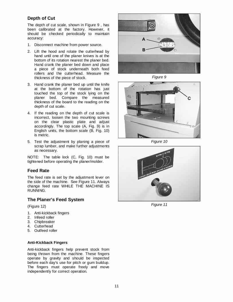
Depth of Cut The depth of cut scale, shown in Figure 9 , has been calibrated at the factory. However, it should be checked periodically to maintain accuracy:
1. Disconnect machine from power source.
2. Lift the hood and rotate the cutterhead by hand until one of the planer knives is at the bottom of its rotation nearest the planer bed. Hand crank the planer bed down and place a piece of stock underneath both feed rollers and the cutterhead. Measure the thickness of the piece of stock.
3. Hand crank the planer bed up until the knife at the bottom of the rotation has just touched the top of the stock lying on the planer bed. Compare the measured thickness of the board to the reading on the depth of cut scale.
4. If the reading on the depth of cut scale is incorrect, loosen the two mounting screws on the clear plastic plate and adjust accordingly. The top scale (A, Fig. 9) is in English units, the bottom scale (B, Fig. 10) is metric.
5. Test the adjustment by planing a piece of scrap lumber, and make further adjustments as necessary.
NOTE: The table lock (C, Fig. 10) must be tightened before operating the planer/molder.
Feed Rate The feed rate is set by the adjustment lever on the side of the machine. See Figure 11. Always change feed rate WHILE THE MACHINE IS RUNNING.
The Planer’s Feed System (Figure 12)
1. Anti-kickback fingers 2. Infeed roller 3. Chipbreaker 4. Cutterhead 5. Outfeed roller
Anti-Kickback Fingers
Anti-kickback fingers help prevent stock from being thrown from the machine. These fingers operate by gravity and should be inspected before each day's use for pitch or gum buildup. The fingers must operate freely and move independently for correct operation.
Figure 9
Figure 10
Figure 11

12
Infeed Roller
The function of the infeed roller is to feed the material into the machine. To provide proper drive, it should be set so that the bottom of its arc is 1/16" (1.6mm) below the arc of the cutterhead knives. The infeed roller is under spring tension and this tension must be sufficient to feed the stock uniformly through the planer without slipping but should not be so tight that it causes damage to the rubber coating on the rolls, or damage to the boards. Adjustment of height and spring tension should be done in conjunction with one another as follows.
To adjust the HEIGHT of infeed roller:
1. Place a bed and feed roll gauge (accessory #2230002), shown in Figure 13, under a planer knife in the cutterhead and raise the table until the gauge contacts the knife at the apex of its curve. Set the gauge to zero.
NOTE: If a bed and feed roll gauge is not available, use a finished block of wood with notches cut out for the table rollers, and a feeler gauge. See Figure 14 for an example of a wood block used as a gauge.)
2. Move the gauge to the extreme right end of the infeed roller and check the measurement. It should be 1/16” below the knife measurement. If it is not, loosen the nut (B, Fig. 15), place a wrench upon the flats of the screw (C, Figure 15) and turn the screw as needed, to raise or lower the infeed roller at the right end.
3. Move the gauge to the extreme left end of the infeed roller and check the measurement. If it is not 1/16” below the knife, make the same adjustment for the left end of the infeed roller.
IMPORTANT: Both ends of the infeed roller should be the same height to help avoid skewing the material as it is fed through the machine.
To adjust the TENSION of the infeed roller:
1. Rotate the lock nut (A, Fig. 14), clockwise to increase tension, counterclockwise to decrease.
Do not over-compress the spring on the infeed roller! Carefully observe the following instructions.
2. Notice that as the spring tension is adjusted, the infeed roller moves up or down. This will affect the height of the roller which was previously set. After tensioning is done, the height adjustment elements (B & C, Figure 15) should be re-adjusted to counteract the
Figure 12
Figure 13
13
tensioning adjustment, and to set the roller back to the original height.
3. The spring which is located above the bushing block (see Figure 15) must not be compressed too tightly, as this will restrict movement of the infeed roller and may cause machine damage due to flexing of the roller. Lift up the infeed roller with your hand – there should still be sufficient travel in the infeed roller.
4. If necessary, continue to adjust tension and height in combination with one another, while being careful to prevent excess spring compression.
5. Repeat for the other end of the infeed roller. The tension should be equal at both ends of the roller.
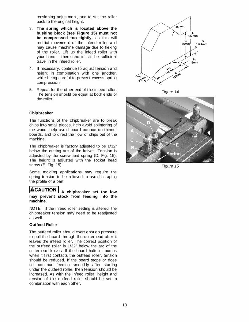
Chipbreaker
The functions of the chipbreaker are to break chips into small pieces, help avoid splintering of the wood, help avoid board bounce on thinner boards, and to direct the flow of chips out of the machine.
The chipbreaker is factory adjusted to be 1/32” below the cutting arc of the knives. Tension is adjusted by the screw and spring (D, Fig. 15). The height is adjusted with the socket head screw (E, Fig. 15).
Some molding applications may require the spring tension to be relieved to avoid scraping the profile of a part.
A chipbreaker set too low may prevent stock from feeding into the machine.
NOTE: If the infeed roller setting is altered, the chipbreaker tension may need to be readjusted as well.
Outfeed Roller
The outfeed roller should exert enough pressure to pull the board through the cutterhead after it leaves the infeed roller. The correct position of the outfeed roller is 1/32” below the arc of the cutterhead knives. If the board halts or bumps when it first contacts the outfeed roller, tension should be reduced. If the board stops or does not continue feeding smoothly after starting under the outfeed roller, then tension should be increased. As with the infeed roller, height and tension of the outfeed roller should be set in combination with each other.
Figure 14
Figure 15

14
To adjust the height of the outfeed roller, loosen the nut (G, Fig. 16), place a wrench upon the flats of the screw (H, Fig. 16) and rotate the screw as needed. Re-tighten the nut (G, Fig. 16) when finished.
To adjust the tension of the outfeed roller, turn the lock nut (F, Fig. 16) as needed.
Do not over-compress the spring on the outfeed roller! Carefully observe the same instructions concerning the infeed roller height and tension adjustments, on pages 11-12.
If the feed rollers are not able to be adjusted to the proper tension, they should be replaced.
Leveling Cutterhead with Bed The cutterhead has been leveled with the surface of the planer bed at the factory. However, should future adjustment be needed, proceed as follows:
1. Place a bed and feed roll gauge (or wood block) beneath one end of the cutterhead. Crank the planer bed up until the cutterhead is just touching the gauge, and check the measurement. Move gauge to the opposite end and check.
2. If the cutterhead is not level with the table, remove the drive belts, and the four hex head screws (A, Fig. 17) holding the platform to the stand. Turn the head assembly over to reach the sprocket adjustments underneath the platform.
3. Loosen the cap screws (B, Fig. 17 & 18) near the idler sprocket to relieve tension on the chain. Remove chain from sprocket on the end that needs adjustment.
4. Turn the sprocket (C, Fig. 18) to raise or lower that edge of the table. NOTE: This adjustment is sensitive and it should not be necessary to turn the sprocket more than one or two teeth.
5. After checking with the gauge to make sure the adjustments are correct, place chain back on sprocket, re-tension idler sprocket, tighten cap screws (B, Fig. 18) and secure head assembly back on to the stand with the four hex head screws (A, Fig. 17).
Figure 16
Figure 17
Figure 18
15
Interlock Switch This machine has an interlocking safety switch located under the hood. The hood must be in the “down” position in order for the planer motor to engage.
If the hood is lifted while the machine is operating, the motor will cut off. The interlock switch must be adjusted so that it will turn off the motor if the hood is raised more than 11/16”.
Do not operate the planer unless the interlock switch is working properly.
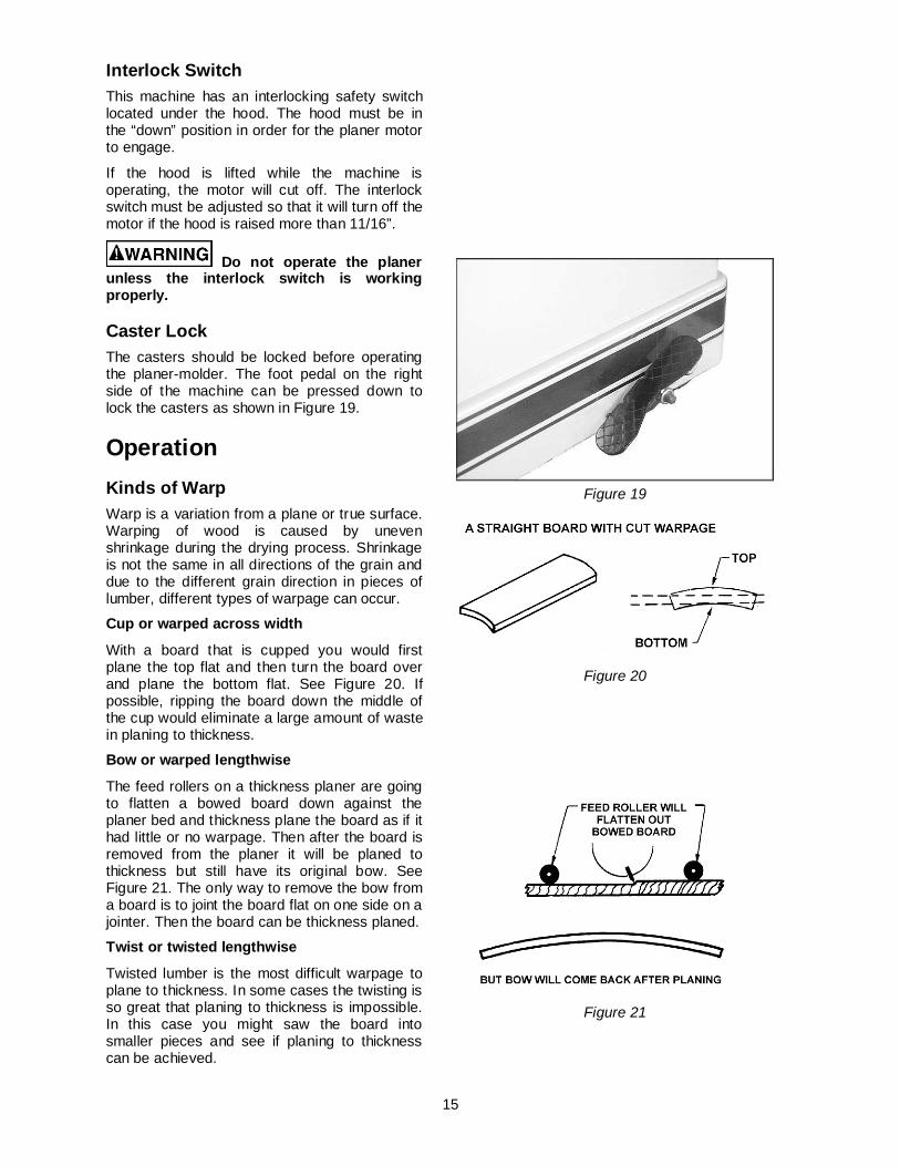
Caster Lock The casters should be locked before operating the planer-molder. The foot pedal on the right side of the machine can be pressed down to lock the casters as shown in Figure 19.
Operation Kinds of Warp Warp is a variation from a plane or true surface. Warping of wood is caused by uneven shrinkage during the drying process. Shrinkage is not the same in all directions of the grain and due to the different grain direction in pieces of lumber, different types of warpage can occur.
Cup or warped across width
With a board that is cupped you would first plane the top flat and then turn the board over and plane the bottom flat. See Figure 20. If possible, ripping the board down the middle of the cup would eliminate a large amount of waste in planing to thickness.
Bow or warped lengthwise
The feed rollers on a thickness planer are going to flatten a bowed board down against the planer bed and thickness plane the board as if it had little or no warpage. Then after the board is removed from the planer it will be planed to thickness but still have its original bow. See Figure 21. The only way to remove the bow from a board is to joint the board flat on one side on a jointer. Then the board can be thickness planed.
Twist or twisted lengthwise
Twisted lumber is the most difficult warpage to plane to thickness. In some cases the twisting is so great that planing to thickness is impossible. In this case you might saw the board into smaller pieces and see if planing to thickness can be achieved.
Figure 19
Figure 20
Figure 21
16
Planing to Desired Thickness Thickness planing is the sizing of material to a desired thickness, while creating a smooth surface parallel to the opposite side of the board. See Figure 22.
The art of thickness planing consists mainly of using good judgment about the depth of cut in various situations. You must take into account not only the width of the stock, but the hardness of the board, its dampness, straightness, grain direction, and grain structure.
The effects of these factors upon the quality of the finished work can only be learned through experience. It is always advisable, whenever working with a new type board, or one with unusual problems, to make test cuts on scrap material if possible prior to working on your finished product.
Depth of Cut The thickness of stock run through the planer is controlled by the distance you adjust the bed from the cutting knife. Always start your work by making a light planing cut. The depth of cut on subsequent passes may be increased, up to 1/8”, however, remember that a light cut creates a finer finish than a heavier cut. See Figure 23.
Never plane more than 1/8” in one pass and never attempt to plane a board under 8” in length.
Thickness Planing Steps To properly use your planer/molder for thickness planing, follow these steps:
1. Measure the thickest part of the board to be planed. Turn the elevation control handle until the scale depth of cut reads the thickness of the board to be planed. Each revolution of the handle raises the bed 1/16” (1.5mm)
2. If desired thickness is greater than 3/16”, make several passes.
NOTE: It is recommended that a board be planed on both sides to the desired thickness. Then the moisture content will be uniform and the drying process will not warp the board. For example, if 3/16” thickness is desired, remove 3/32” from each side.
Figure 22
Figure 23
17
3. Stand to one side of the machine and start the board under the infeed roller so that it travels in a straight line. As the infeed roller takes hold, let go and remain standing to one side of the unit – never directly in line with the board. The power feed will complete the travel without further pushing or pulling.
Planing for Finish Planing for a smooth finish is best accomplished by taking light cuts on the board. However, several other things are important to achieve a smooth finish.
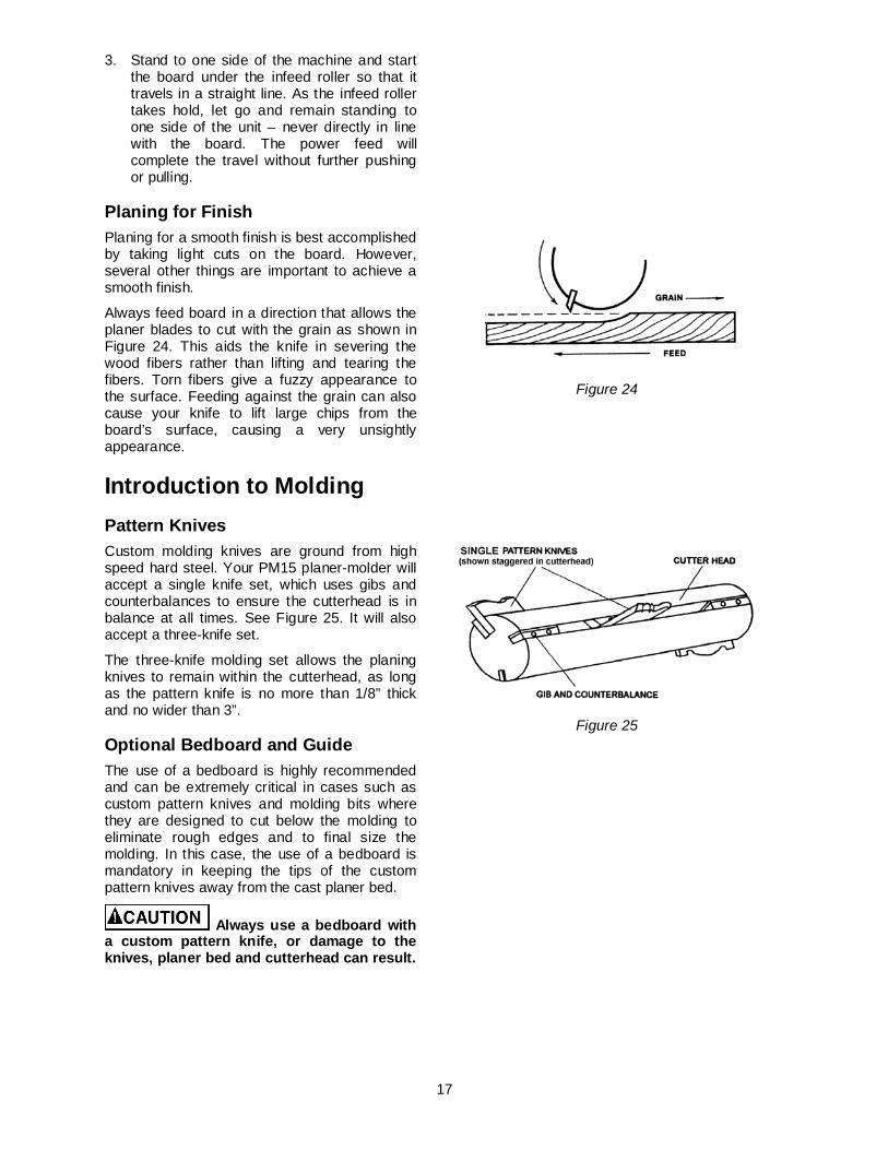
Always feed board in a direction that allows the planer blades to cut with the grain as shown in Figure 24. This aids the knife in severing the wood fibers rather than lifting and tearing the fibers. Torn fibers give a fuzzy appearance to the surface. Feeding against the grain can also cause your knife to lift large chips from the board’s surface, causing a very unsightly appearance.
Introduction to Molding Pattern Knives Custom molding knives are ground from high speed hard steel. Your PM15 planer-molder will accept a single knife set, which uses gibs and counterbalances to ensure the cutterhead is in balance at all times. See Figure 25. It will also accept a three-knife set.
The three-knife molding set allows the planing knives to remain within the cutterhead, as long as the pattern knife is no more than 1/8” thick and no wider than 3”.
Optional Bedboard and Guide The use of a bedboard is highly recommended and can be extremely critical in cases such as custom pattern knives and molding bits where they are designed to cut below the molding to eliminate rough edges and to final size the molding. In this case, the use of a bedboard is mandatory in keeping the tips of the custom pattern knives away from the cast planer bed.
Always use a bedboard with a custom pattern knife, or damage to the knives, planer bed and cutterhead can result.
Figure 24
Figure 25

18
Homemade Bedboard A homemade bedboard can be made as shown in Figure 26. Permanent guide rails are mounted as shown.
Homemade Featherboard For face molding, a homemade guide and comb or featherboard can be combined to position stock for desired pattern cuts. See Figure 27. Select a straight piece of hardwood for the guide. This piece should be 2” x 1/2” and at least 27-1/4” long. The guide should be exactly parallel to the milled edge of the planer bed. The guide can be held in place with C-clamps. You will have to cut clearances in the guide so the guide will fit beneath the rollers.
A featherboard can be of great help in guiding stock. It is quickly made from any piece of 1” thick stock, approximately 8” long and 3” wide. Saw the parallel slots about 4” deep and 1/8” apart. The feather board can be C-clamped at any position to exert a spring tension to hold the stock against the guide.
Homemade Guide Set-Up for Edge Molding Figure 28 shows a wooden guide set-up for edge molding. The guides are C-clamped on each side of the stock and are within 3/4” of the top edge to provide maximum support so that the narrow stock will travel beneath the knife.
Installing Single Pattern Knives Pattern knives are easy to install and adjust.
Always disconnect machine from power source before changing knives or molding bits. Always use the gib(s) supplied with a particular molding knife.
1. Loosen the gib set screws and tap all gibs down to release the planer knives.
2. Remove the planer knives, then the gibs and jack screws. Clean the cutterhead slots and the custom pattern knife thoroughly with a nonflammable solvent to remove all wood, dust, gum, and any protective coatings.
3. Re-install the jack screws. Install the aluminum gib and then the pattern knife into one of the cutterhead slots. See Figure 29. Tighten the gib set screws. Double check during this tightening, to insure against the knife creeping up during the tightening process. If necessary, tap the knife down with a hard wood block until it has bottomed out in the cutterhead slot.
Figure 26
Figure 27
Figure 28
Figure 29

19
4. Install one steel gib and the steel counterweight in the second slot. Tighten the gib set screws. (The steel gib and counterweight are ground to balance the cutterhead.) See Figure 30.
5. Install the other steel gib and counterweight in the third slot and tighten the gib set screws.
Do not interchange counter-weights between sets of pattern knives. They are properly sized for the one set. Machine vibration may result if counterweights are accidentally interchanged.
Installing Three-Knife Set 1. Loosen the set screws on the gib in the first
slot. Tap the gib down to release the planer knives.
2. Insert the pattern knife next to the planer knife, as shown in Figure 31. Note: Small molder knives (1” and under) will require a spacer.
3. Mount the molding cutter gauge (A, Fig. 32) to the theaded hole in the casting with the socket head cap screw, lock washer and flat washer (B, Fig. 32). The guide may be attached to either side.
4. Adjust the gauge (A, Fig. 32) so that the end of it meets the pattern knife, then tighten the screw (B, Fig. 32).
5. Tighten gib screws to hold pattern knife in place.
6. Rotate the cutterhead and adjust the other two knives to meet the the gauge (A, Fig. 32).
7. Securely tighten all gib screws and remove gauge from machine.
Pattern Knife Clearance The knives should clear both the chipbreaker and the chip deflector.
Check the knife for clearance by rotating the chipbreaker toward the knife and rotating the cutterhead slowly by hand. There should be no contact between the pattern knife and chip breaker. If there is contact, loosen the gib set screw and tap the gib down, making sure the knife is bottomed in the cutterhead slot. Re-tighten the gib set screws when the knife has been properly adjusted.
Figure 30
Figure 31
Figure 32
20
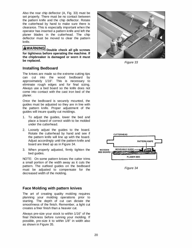
Also the rear chip deflector (A, Fig. 33) must be set properly. There must be no contact between the pattern knife and the chip deflector. Rotate the cutterhead by hand to make sure there is clearance. This is especially important when the operator has inserted a pattern knife and left the planer blades in the cutterhead. The chip deflector must be moved to clear the pattern knife.
Double check all gib screws for tightness before operating the machine. If the chipbreaker is damaged or worn it must be replaced.
Installing Bedboard The knives are made so the extreme cutting tips can cut into the wood bedboard by approximately 1/16”. This is necessary to eliminate rough edges and for final sizing. Always use a bed board so the knife does not come into contact with the cast iron bed of the planer.
Once the bedboard is securely mounted, the guides must be adjusted so they are in line with the pattern knife. Proper adjustment of the guides will insure quality cut moldings.
1. To adjust the guides, lower the bed and place a board of correct width to be molded under the cutterhead.
2. Loosely adjust the guides to the board. Rotate the cutterhead by hand and see if the pattern knife will line up with the board. Adjust accordingly until the pattern knife and board are lined up as in Figure 34.
3. When properly adjusted, firmly tighten the bed guides.
NOTE: On some pattern knives the cutter trims a small portion of the width away as it cuts the pattern. The outfeed guides on the bedboard must be adjusted to compensate for the decreased width of the molding.
Face Molding with pattern knives The art of creating quality molding requires planning your molding operations prior to starting. The depth of cut can dictate the smoothness of the finish. Remember, a light cut creates a finer finish than a heavier cut.
Always pre-size your stock to within 1/16” of the final thickness before running your molding. If possible, pre-size it to within 1/8” in width also as shown in Figure 35.
Figure 33
Figure 34

21
Before you begin molding, you must also consider the hardness of the board, its moisture content, straightness, grain direction, and grain structure. All of these factors will play a part in the quality of your molding.
Stand to one side of the machine and start the board under the infeed roller so that it travels in a straight line. When the feed roller takes hold, let go of the piece and remain standing to one side of the machine – not in direct line with the board. The power feed completes the travel without further pushing or pulling.
Edge Molding with pattern knives This procedure is easily done by installing the proper pattern knife and setting up the bedboard and guide system with guides tall enough to hold the stock on edge.
Edge Planing
A bedboard must be installed on the planer when edge planing.
Edge planing can be done on stock up to 3/4” thick and 11” wide with the following set-up: Install the rabbet cutter knife, at the right or left edge of the cutterhead, so that the rabbet knife extends inside of the guide approximately 1/16” to 1/8” or just enough to clean up the stock. See Figure 36.
If you have not already done so, install counterweights in the remaining two cutterhead slots. The rabbet knife is locked in place with the aluminum gib provided.
NOTE: When the rabbet knife becomes dull on one side, move the rabbet knife and counterweight set-up to the opposite side of the cutterhead. This will give you a fresh cutting edge with which to work.
Common Molding Applications Practice and experience will greatly affect the quality of molding that you produce. Once you become familiar with the set-ups for the different molding applications, you will easily be turning out quality molding on every run. Some of the more common applications are described below.
Back Relief Back reliefs are used to create a better fit over irregular surfaces. With less wood contact, the molding matches irregular surfaces more easily. See Figure 37. The back relief should be formed on a piece of wood before it is molded to finished thickness.
Figure 35
Figure 36
Figure 37
22
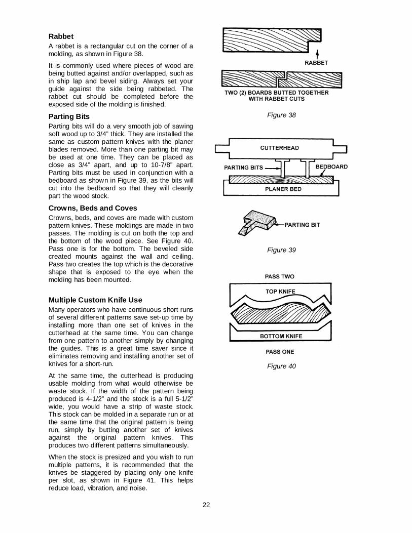
Rabbet A rabbet is a rectangular cut on the corner of a molding, as shown in Figure 38.
It is commonly used where pieces of wood are being butted against and/or overlapped, such as in ship lap and bevel siding. Always set your guide against the side being rabbeted. The rabbet cut should be completed before the exposed side of the molding is finished.
Parting Bits Parting bits will do a very smooth job of sawing soft wood up to 3/4” thick. They are installed the same as custom pattern knives with the planer blades removed. More than one parting bit may be used at one time. They can be placed as close as 3/4” apart, and up to 10-7/8” apart. Parting bits must be used in conjunction with a bedboard as shown in Figure 39, as the bits will cut into the bedboard so that they will cleanly part the wood stock.
Crowns, Beds and Coves Crowns, beds, and coves are made with custom pattern knives. These moldings are made in two passes. The molding is cut on both the top and the bottom of the wood piece. See Figure 40. Pass one is for the bottom. The beveled side created mounts against the wall and ceiling. Pass two creates the top which is the decorative shape that is exposed to the eye when the molding has been mounted.
Multiple Custom Knife Use Many operators who have continuous short runs of several different patterns save set-up time by installing more than one set of knives in the cutterhead at the same time. You can change from one pattern to another simply by changing the guides. This is a great time saver since it eliminates removing and installing another set of knives for a short-run.
At the same time, the cutterhead is producing usable molding from what would otherwise be waste stock. If the width of the pattern being produced is 4-1/2” and the stock is a full 5-1/2” wide, you would have a strip of waste stock. This stock can be molded in a separate run or at the same time that the original pattern is being run, simply by butting another set of knives against the original pattern knives. This produces two different patterns simultaneously.
When the stock is presized and you wish to run multiple patterns, it is recommended that the knives be staggered by placing only one knife per slot, as shown in Figure 41. This helps reduce load, vibration, and noise.
Figure 38
Figure 39
Figure 40

23
Maintenance Build-up of sawdust and other debris can cause your machine to plane and mold inaccurately. Periodic cleaning and waxing is not only recommended, but necessary for accurate work.
Always disconnect machine from power source before performing maintenance.
1. Close fitting parts, such as gibs and the planer cutterhead slots should be wiped with a cloth and non-flammable solvent and freed from clinging foreign matter and then replaced in respective position, slightly dampened with oil. Do not soak these parts in oil.
2. Occasional use of paste wax on the bed will prevent rust and reduce friction to ease feeding.
NOTE: Using too much paste wax will allow the wax to rub off onto the planed wood and contaminate the wood surface affecting subsequent finishing.
3. Remove resin and other accumulations from feed rollers and bed with a non-flammable solvent
4. Periodically check all the chains for proper tension and adjust accordingly if required.
Lubrication 1. The recommended lubrication for roller
chains used in medium to slow speed operation is to simply wipe the chain clean. When there is an appreciable build up of dust, dirt or wood shavings, use an oil cloth but never pour the oil directly on the chain. Over-oiling defeats the purpose of the lubrication, since it tends to invite the collecting of dust, shavings, etc. and works into members of the chain. This hastens wear and leads to premature replacement.
2. The bearings on the cutterhead are factory lubricated and sealed. They require no further attention.
3. When using the planer/molder in a high humidity area, the four corner screws, shown in Figure 42, should be coated with grease or a rust-preventative.
4. The oil in the gearbox should be drained and replaced about every 2,500 hours of use. Multi-purpose 70 to 90 weight gearbox oil is suitable.
Figure 41
Figure 42
24
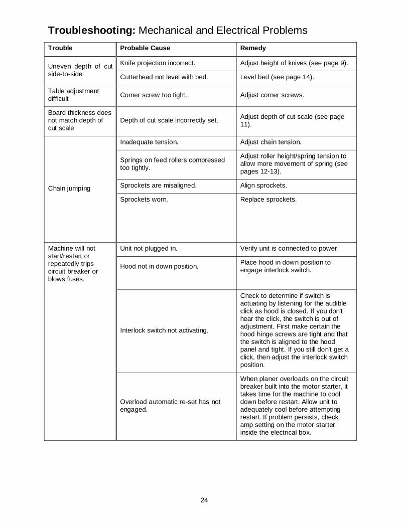
Troubleshooting: Mechanical and Electrical Problems Trouble Probable Cause Remedy
Uneven depth of cut side-to-side
Knife projection incorrect. Adjust height of knives (see page 9).
Cutterhead not level with bed. Level bed (see page 14).
Table adjustment difficult Corner screw too tight. Adjust corner screws.
Board thickness does not match depth of cut scale
Depth of cut scale incorrectly set. Adjust depth of cut scale (see page 11).
Chain jumping
Inadequate tension. Adjust chain tension.
Springs on feed rollers compressed too tightly.
Adjust roller height/spring tension to allow more movement of spring (see pages 12-13).
Sprockets are misaligned. Align sprockets.
Sprockets worn.
Replace sprockets.
Machine will not start/restart or repeatedly trips circuit breaker or blows fuses.
Unit not plugged in. Verify unit is connected to power.
Hood not in down position.
Place hood in down position to engage interlock switch.
Interlock switch not activating.
Check to determine if switch is actuating by listening for the audible click as hood is closed. If you don’t hear the click, the switch is out of adjustment. First make certain the hood hinge screws are tight and that the switch is aligned to the hood panel and tight. If you still don’t get a click, then adjust the interlock switch position.
Overload automatic re-set has not engaged.
When planer overloads on the circuit breaker built into the motor starter, it takes time for the machine to cool down before restart. Allow unit to adequately cool before attempting restart. If problem persists, check amp setting on the motor starter inside the electrical box.

25
Trouble Probable Cause Remedy
Machine will not start/restart or repeatedly trips circuit breaker or blows fuses.
(cont.)
Planer frequently trips.
One cause of overload trips which is not electrical in nature is too heavy a cut. The solution is to take a lighter cut. If too deep a cut is not the problem, then check the amp setting on the overload relay. Match the full load amps on the motor as noted on the motor plate. If amp setting is correct, there is probably a loose electrical lead or a failed component. See “Motor starter failure” below.
Building circuit breaker trips or fuse blows.
Verify that the planer is on a circuit of correct size. If circuit size is correct, there is probably a loose electrical lead. Also check amp setting on motor starter.
Loose electrical connections.
Go through all of the electrical connections on the planer including motor connections, verifying the tightness of each. Look for any signs of electrical arcing which is a sure indicator of loose connection or circuit overload.
Failed or broken interlock switch.
Examine the switch and switch housing for any sign of damage. If damage is seen, replace components. If the switch circuitry is suspect, you have two options: have a qualified electrician test the switch for function, or purchase a new switch and establish if that was the problem on changeout.
Motor/starter failure (how to distinguish).
Examine motor starter for burned or failed components. If damage is found, replace motor starter. If motor starter looks okay but is still suspect, you have two options: have a qualified electrician test the motor starter for function, or purchase a new starter and establish if that was the problem on changeout.
If you have access to a voltmeter, you can separate a starter failure from a motor failure by first, verifying incoming voltage at 220+/-20 and second, checking the voltage between starter motor at 220+/-20. If incoming voltage is incorrect, you have a power supply problem. If voltage between starter and motor is incorrect, you have a starter problem. If voltage between starter and motor is correct, you have a motor problem.

26
Trouble Probable Cause Remedy
Motor failure.
If electric motor is suspect, you have two options: Have a qualified electrician test the motor for function, or remove the motor and take it to a qualified motor repair shop for testing.
Miswiring of the unit. Double check all connections and consult the electrical breakdowns if changes are needed.
On/off switch failure.
If the on/off switch is suspect, you have two options: Have a qualified electrician test the switch for function, or purchase a new on/off switch and establish if that was the problem on changeout.

27
Troubleshooting: Operating Problems Trouble Probable Cause Remedy
Snipe (Note: Snipe can not be eliminated, but can be so minimized as to become negligible.)
Dull knives Sharpen or replace knives.
Inadequate support of long boards. Use extensions to support boards.
Uneven feed roller pressure front to back.
Adjust feed roller tension.
Corner screws loose. Tighten corner screws.
Lumber not butted properly. Butt end to end each piece of stock as they pass through the planer.
Fuzzy grain Planing wood with high moisture content.
Remove moisture by drying, or use different stock.
Dull knives. Sharpen or replace knives.
Torn grain
Too heavy a cut. Adjust proper depth of cut.
Knives cutting against grain. Cut with grain whenever possible.
Dull knives. Sharpen or replace knives.
Rough/Raised grain
Dull knives. Sharpen or replace knives.
Too heavy a cut. Adjust proper depth of cut.
Moisture content too high. Remove moisture from wood or use different stock.
Rounded, glossy surface Dull knives. Sharpen or replace knives.
Wavy molding pattern Improper guide set-up. Review proper guide set-up
Horizontal play of planer bed. Remove play in planer bed.
Tear-out at end of molding
Improper guide set-up. Review proper guide set-up.
Inadequate outfeed pressure. Adjust feed roller tension.
Poor feeding of lumber
Inadquate feed roller pressure. Adjust feed roller tension. If proper tension cannot be achieved, replace feed rollers.
Planer bed rough or dirty. Clean pitch and residue, and was planer bed.
Transmission v-belt slipping. Tighten transmission v-belt.
Surface of feed rollers too smooth. Lightly roughen the feed roller surface with sandpaper.

28
Replacement Parts Replacement parts are listed on the following pages. To order parts or reach our service department, call 1-800-274-6848, Monday through Friday (see our website for business hours, www.powermatic.com). Having the Model Number and Serial Number of your machine available when you call will allow us to serve you quickly and accurately.

29
Parts List: Base Assembly
Index No. Part No. Description Size Qty 1 .............. 6286639 ..................Round Head Screw ..................................M6 x 10.P x 12Lg............... 26 2 .............. 6296220 ..................Washer ...................................................6mm x 13 x 1T................... 19 3 .............. 6296221 ..................Hex Cap Screw .......................................M8 x 1.25P x 70Lg ............... 4 4 .............. 6296222 ..................Washer ...................................................8mm x 22 x 3T..................... 4 5 .............. 6296223 ..................Rear Lead Screw ................................................................................ 2 6 .............. TS-1504031 ............Socket Head Cap Screw ..........................M8 x 1.25P x 16Lg ............. 10 7 .............. 6296224 ..................Flange ............................................................................................... 4 8 .............. 6296225 ..................Bearing ...................................................6202-2NSE ......................... 4 9 .............. 6296226 ..................Bushing.............................................................................................. 4 10 ............ 6296227 ..................Bearing Housing ................................................................................. 4 11 ............ 6296228 ..................Bracket .............................................................................................. 4 12 ............ 6296229 ..................Base .................................................................................................. 1 13 ............ 6296199 ..................Shoulder Bolt...........................................1/4-20NC ............................ 1 14 ............ 6296231 ..................Bracket .............................................................................................. 1 15 ............ 6296198 ..................Lock Nut .................................................M5 x 0.8 .............................. 2 16 ............ JTM1055-B18-1 .......Round Head Screw ..................................M5 x 0.8P x 10Lg................. 2 17 ............ 6296232 ..................Bracket .............................................................................................. 1 18 ............ 6296233 ..................Round Head Screw ..................................M8 x 1.25P x 12Lg ............... 8 19 ............ 6296234 ..................Hinge ................................................................................................. 2 20 ............ 6296235 ..................Rear Bracket ...................................................................................... 1 21 ............ 6296236 ..................Right Side Cover ................................................................................ 1 22 ............ 6296237 ..................Round Head Screw ..................................M4 x 0.7P x 12Lg................. 8 23 ............ 6296238 ..................Start Switch ........................................................................................ 1 24 ............ 6296239 ..................Stop Switch ........................................................................................ 1 25 ............ 6296240 ..................Washer ...................................................4mm x 10 x 1T..................... 6 26 ............ 6296241 ..................Left Side Cover................................................................................... 1 27 ............ 6296242 ..................Switch Box ......................................................................................... 2 28 ............ TS-1540021 ............Hex Nut...................................................M4 x 0.7 .............................. 7 29 ............ 6296243 ..................Contact Cord ...................................................................................... 1 30 ............ 6296244 ..................Chain ......................................................410-146P ............................ 1 31 ............ 6296245 ..................Sprocket ............................................................................................ 4 32 ............ 6296246 ..................Lock Nut .................................................M10 x 1.25 .......................... 4 33 ............ 6296247 ..................Washer ...................................................8mm x 19 x 2T..................... 2 34 ............ 6296248 ..................Bracket .............................................................................................. 1 35 ............ 6296249 ..................Shaft .................................................................................................. 1 36 ............ 6296250 ..................S-Ring ....................................................STW-15 .............................. 1 37 ............ 6296251 ..................Sprocket ............................................................................................ 1 38 ............ 6296252 ..................Front Bracket...................................................................................... 1 39 ............ 6296253 ..................Round Head Screw ..................................M6 x 1.0P x 15Lg................. 1 40 ............ 6296254 ..................Round Head Screw ..................................M4 x 0.7P x 25Lg................. 2 41 ............ 6296255 ..................Limit Switch ........................................................................................ 1 42 ............ 111001-00-43 ..........Spring Pin ...............................................4 x 25.................................. 1 43 ............ 6296256 ..................Lead Screw ........................................................................................ 1 44 ............ JWP12-150 .............Tooth Washer..........................................BW-4 .................................. 1 45 ............ 6296257 ..................Check Nut ...............................................M6 x 1.0 .............................. 1 46 ............ 6296258 ..................Spring ................................................................................................ 1 47 ............ 6296259 ..................Pointer ............................................................................................... 1 48 ............ 6296260 ..................Shaft .................................................................................................. 1 49 ............ 6286482 ..................E-Ring ....................................................ETW-4 ................................ 1 50 ............ 6296261 ..................Scale ................................................................................................. 1 51 ............ 6296262 ..................Spring ................................................................................................ 1 52 ............ 6296263 ..................Front Lead Screw ............................................................................... 1 53 ............ 6012062 ..................E-Ring ....................................................ETW-12 .............................. 1 54 ............ 6296311 ..................Lock Knob .......................................................................................... 1

30
Base Assembly

31
Parts List: Gearbox Assembly
Index No. Part No. Description Size Qty ................ 6296310A................Gearbox Assembly (Items 1 thru 40) .................................................... 1 (for serial no. 0412PM15488 and higher) 1 .............. 6296264A................Gearbox Body .................................................................................... 1 2 .............. 6296265 ..................Pin ..................................................................................................... 2 3 .............. 6296266 ..................Bushing.............................................................................................. 5 4 .............. 6296267 ..................Gear .................................................................................................. 1 5 .............. 6296268 ..................Key .........................................................4 x 4 x 6 mm........................ 2 6 .............. 6296269 ..................Gear .................................................................................................. 1 7 .............. 6296270 ..................Gear .................................................................................................. 1 8 .............. 6296271 ..................Gear Shaft ......................................................................................... 1 9 .............. 6296272 ..................Gear Assembly ................................................................................... 1 10 ............ 6296273 ..................Key .........................................................4 x 4 x 40 mm...................... 1 11 ............ 6296274 ..................Shaft .................................................................................................. 1 12 ............ 6296275 ..................S-Ring ....................................................STW-12 .............................. 1 13 ............ 6296276A................Gearbox Cover ................................................................................... 1 14 ............ 6296277 ..................Socket Head Cap Screw ..........................M6 x 1.0P x 80Lg................. 4 15 ............ 6296315 ..................Oil Plug ...................................................PT1/4-19 ............................. 2 16 ............ BB-6000ZZ ..............Ball Bearing.............................................6000ZZ ............................... 1 17 ............ BB-6201ZZ ..............Ball Bearing.............................................6201ZZ ............................... 1 18 ............ 6296314 ..................Oil Seal ...................................................TC14 x 25 x 7 ...................... 1 19 ............ 6296317A................Packing .............................................................................................. 1 20 ............ 6296318 ..................O-Ring ....................................................P9....................................... 1 21 ............ 6296210 ..................Sprocket ............................................................................................ 1 22 ............ 6296211 ..................S-Ring ....................................................STW-17 .............................. 1 23 ............ 6296281 ..................Knob .................................................................................................. 1 24 ............ 6286490 ..................Socket Head Cap Screw ..........................M6 x 1.0P x 15 .................... 7 25 ............ 6296283 ..................Clutch ................................................................................................ 1 26 ............ 6296284 ..................Rod ................................................................................................... 1 27 ............ 6296319 ..................Bracket .............................................................................................. 1 28 ............ 6296320 ..................Shaft .................................................................................................. 1 29 ............ 6296321 ..................Idle .................................................................................................... 2 30 ............ 6296322 ..................Shaft .................................................................................................. 2 31 ............ 6296323 ..................Bracket .............................................................................................. 1 32 ............ TS-2311061 ............Hex Nut...................................................M6 x 1.0P............................ 4 33 ............ 6296324 ..................Spring ................................................................................................ 2 34 ............ TS-1550041 ............Washer ...................................................6.3mm x 13 x 1 .................... 1 35 ............ TS-1503071 ............Socket Head Cap Screw ..........................M6 x 1.0P x 30Lg................. 1 36 ............ TS-1503051 ............Socket Head Cap Screw ..........................M6 x 1.0P x 20Lg................. 1 37 ............ PM15-237 ...............Shaft .................................................................................................. 1 38 ............ PM15-238 ...............Hanger............................................................................................... 1 39 ............ SB-5MM ..................Steel Ball.................................................5mm ................................... 1 40 ............ PM15-240 ...............Spring ................................................................................................ 1

32
Gearbox Assembly

33
Parts List: Stand Assembly
Index No. Part No. Description Size Qty 1 .............. TS-1490031 ............Hex Cap Screw .......................................M8 x 1.25P x 20Lg ............... 1 2 .............. TS-1551061 ............Lock Washer ...........................................8mm ................................... 5 3 .............. 6296175 ..................Special Washer .......................................8mm x 32 x 4T..................... 1 4 .............. 6296286 ..................Belt .........................................................M57 .................................... 3 5 .............. 6296287 ..................Motor Pulley ....................................................................................... 1 6 .............. 6296288 ..................Key .........................................................5 x 5 x 35 mm...................... 1 7 .............. 6296289 ..................Motor ......................................................5HP, 1 PH, 230V ................. 1 9 .............. TS-1540061 ............Hex Nut...................................................M8 x 1.25 ............................ 4 10 ............ 6296279 ..................Washer ...................................................8mm x 16 x 2T..................... 3 11 ............ TS-1523041 ............Socket Set Screw ....................................M6 x 1.0P x 12Lg................. 1 12 ............ 6296290 ..................Motor Bracket ..................................................................................... 1 13 ............ 6296291 ..................Washer ...................................................8mm x 19 x 2T..................... 4 14 ............ TS-1490061 ............Hex Cap Screw .......................................M8 x 1.25P x 35Lg ............... 4 15 ............ 6296292 ..................Support Bar ........................................................................................ 2 16 ............ 6296293 ..................Collar ................................................................................................. 1 17 ............ 6296294 ..................Strain Relief Bushing ...............................SB9R-2 ............................... 2 18 ............ TS-1540071 ............Hex Nut...................................................M10 x 1.5 ............................ 2 19 ............ 6296295 ..................Washer ...................................................10mm x 28 x 3 ..................... 2 20 ............ 6296296 ..................Adjustment Bolt .................................................................................. 1 21 ............ TS-1523011 ............Socket Set Screw ....................................M6 x 1.0P x 6Lg .................. 4 22 ............ 6296213 ..................Eccentric Cam .................................................................................... 2 23 ............ 6296297 ..................Spring ................................................................................................ 2 24 ............ 6296298 ..................Spring Pin ...............................................4 x 20.................................. 2 25 ............ 6296299 ..................Shaft .................................................................................................. 1 26 ............ 6296300 ..................Power Cord ........................................................................................ 1 27 ............ 6296301 ..................Lock Nut .................................................M4 x 0.7 .............................. 2 28 ............ 6296302 ..................Door .................................................................................................. 1 29 ............ 6286639 ..................Round Head Screw ..................................M6 x 1.0P x 12Lg................. 4 30 ............ 6296303 ..................Round Head Screw ..................................M4 x 0.7P x 6Lg .................. 2 31 ............ 6296304 ..................Rear Door .......................................................................................... 1 32 ............ 6296305 ..................Latch ................................................................................................. 1 33 ............ 6296306 ..................Stand ................................................................................................. 1 34 ............ TS-0640091 ............Lock Nut .................................................3/8-16NC ............................ 4 35 ............ 6296307 ..................Wheel ................................................................................................ 4 36 ............ TS-0060111 ............Hex Cap Screw .......................................3/8-16NC x 2-1/2 ................. 4 37 ............ TS-1541041 ............Lock Nut .................................................M10 x 1.5 ............................ 1 38 ............ 6296308 ..................Washer ...................................................10mm x 22 x 2T ................... 1 39 ............ 6296309 ..................Foot Brake ......................................................................................... 1 40 ............ 6296187 ..................Round Head Screw ..................................M4 x 0.7P x 45Lg................. 2 41 ............ 6296230 ..................Control Cord ....................................................................................... 1 42 ............ 6296282 ..................Magnetic Switch ................................................................................. 1 43 ............ 6296285 ..................Motor Cord ......................................................................................... 1
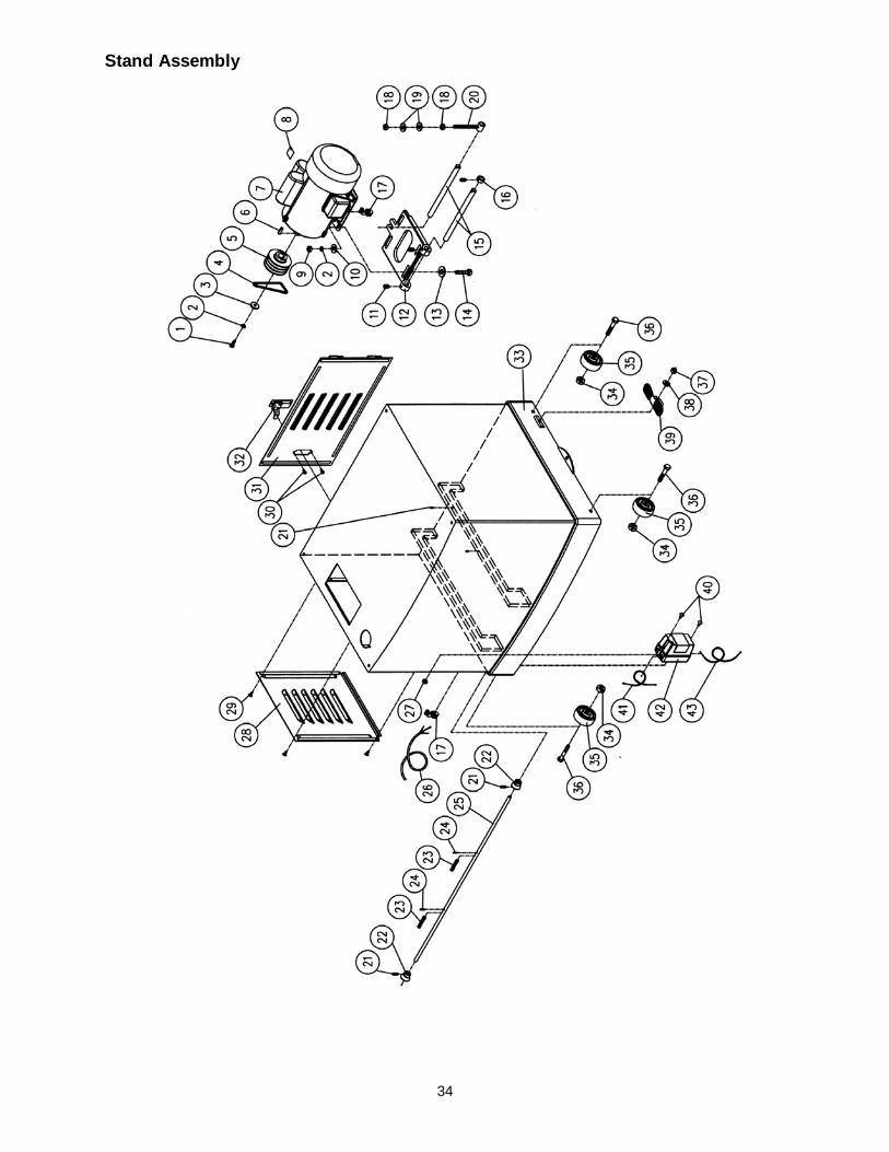
34
Stand Assembly

35
Parts List: Cutterhead, Hood and Table Assembly
Index No. Part No. Description Size Qty 1 .............. 6286490 ..................Socket Head Cap Screw ..........................M6 x 1.0P x 15Lg............... 23 2 .............. TS-1551041 ............Lock Washer ...........................................6mm ................................. 18 3 .............. 6296169 ..................Left Support Plate ............................................................................... 1 4 .............. 6296170 ..................Washer ...................................................6mm x 13 x 2T................... 10 5 .............. TS-1503051 ............Socket Head Cap Screw ..........................M6 x 1.0 x 20....................... 2 6 .............. 6292641 ..................Hex Nut...................................................M6 x 1.0 .............................. 3 7 .............. TS-1504081 ............Socket Head Cap Screw ..........................M8 x 1.25P x 40 .................. 2 8 .............. 6296171 ..................Washer ...................................................8mm x 22 x 3T..................... 2 9 .............. 6296172 ..................Spring ................................................................................................ 2 10 ............ 6296173 ..................Socket Head Cap Screw ..........................M8 x 1.25P x 15Lg ............... 2 11 ............ 6296174 ..................Chipbreaker ....................................................................................... 1 12 ............ TS-1504041 ............Hex Cap Screw .......................................M8 x 1.25P x 20Lg ............... 1 13 ............ 6296175 ..................Special Washer .......................................8mm x 32 x 4T..................... 1 14 ............ 6296176 ..................Cutterhead Pulley ............................................................................... 1 15 ............ TS-1504031 ............Socket Head Cap Screw ..........................M8 x 1.25P x 16Lg ............... 6 16 ............ 6296177 ..................Washer ...................................................8mm x 19 x 2T..................... 6 17 ............ TS-2342101 ............Lock Nut .................................................M10 x 1.5 ............................ 4 18 ............ 6296178 ..................Adjustment Shaft ................................................................................ 4 19 ............ 6296179 ..................Adjustment Nut ................................................................................... 4 20 ............ 6296180 ..................Adjustment Screw ............................................................................... 4 21 ............ 6296181 ..................Spring ................................................................................................ 4 22 ............ 6296182 ..................Left Cutterhead Bracket ...................................................................... 1 23 ............ 6296183 ..................Bushing.............................................................................................. 4 24 ............ 6296184 ..................Rubber Roller ..................................................................................... 2 25 ............ 6296185 ..................Locating Rod ...................................................................................... 2 26 ............ 6296186 ..................Ball Bearing.............................................6205-2NSE ......................... 1 27 ............ 6012165 ..................Key .........................................................8 x 7 x 30 mm...................... 1 28 ............ 6296055 ..................Flat Head Screw ......................................M5 x 0.8P x 12Lg................. 6 29 ............ 6296188 ..................Cutterhead ......................................................................................... 1 30 ............ 6296189 ..................Knife Lock Bar .........................................7”L ...................................... 6 31 ............ TS-1524031 ............Socket Set Screw ....................................M8 x 1.25P x 12Lg ............. 27 32 ............ 6296190 ..................Knife (set of 3) .................................................................................... 1 33 ............ 6296191 ..................Knife Lock Bar .........................................4”L ...................................... 3 34 ............ 6296192 ..................Lock Bar Spacer ................................................................................. 9 35 ............ TS-0207011 ............Socket Head Cap Screw ..........................1/4-20NC x 3/8 .................... 2 36 ............ 6296193 ..................Bracket .............................................................................................. 3 37 ............ 6296194 ..................Chip Deflector .................................................................................... 1 38 ............ 6296195 ..................Hex Cap Screw w/Washer ........................M6 x 1.0P x 12Lg................. 8 39 ............ 6296196 ..................Dust Chute ......................................................................................... 1 40 ............ 6296197 ..................Dust Hood .......................................................................................... 1 41 ............ 6296198 ..................Lock Nut .................................................M5 x 0.8 .............................. 2 42 ............ 6296199 ..................Special Bolt w/ Shoulder ..........................1/4-20NC ............................ 1 43 ............ JTM1055-B18-1 .......Round Head Screw ..................................M5 x 0.8P x 10Lg............... 12 44 ............ TS-1504041 ............Socket Head Cap Screw ..........................M8 x 1.25P x 20Lg ............... 1 45 ............ 6296200 ..................Washer ...................................................8mm x 30 x 3T..................... 3 46 ............ TS-1502051 ............Socket Head Cap Screw ..........................M5 x 0.8P x 20Lg................. 1 47 ............ 6296201 ..................Right Cutterhead Bracket .................................................................... 1 48 ............ 6296202 ..................Chain (outfeed roll to infeed roll) ...............06B-64P.............................. 1 49 ............ TS-1490041 ............Hex Cap Screw .......................................M8 x 1.25P x 25Lg ............... 2 50 ............ 6296203 ..................Handle ............................................................................................... 1 51 ............ 6296204 ..................Top Cover .......................................................................................... 1 52 ............ 6296205 ..................Rubber Bumper .................................................................................. 1 53 ............ 6296206 ..................Anti-Kickback Shaft ............................................................................. 1 54 ............ 6296207 ..................Anti-Kickback Finger ......................................................................... 42 55 ............ 6296208 ..................Anti-Kickback Collar .......................................................................... 48 56 ............ 6012038 ..................Bearing ...................................................6204-2NSE ......................... 1 57 ............ 6296209 ..................Gear .................................................................................................. 1

36
58 ............ 6296210 ..................Sprocket ............................................................................................ 2 59 ............ 6296211 ..................S-Ring ....................................................STW-17 .............................. 2 60 ............ 6296212 ..................Limiter................................................................................................ 1 61 ............ TS-1521021 ............Set Screw ...............................................M4 x 0.7P x 6Lg .................. 1 62 ............ 6296214 ..................Middle Table ...................................................................................... 1 63 ............ 6296215 ..................Handle Assembly................................................................................ 1 64 ............ 6296216 ..................Handwheel ......................................................................................... 1 65 ............ 6296217 ..................Hex Cap Screw .......................................M6 x 1.0P x 20Lg................. 1 66 ............ 6296218 ..................Right Support Plate ............................................................................. 1 67 ............ TS-1540031 ............Hex Nut...................................................M5 x 0.8 .............................. 1 68 ............ 6296219 ..................Sponge .............................................................................................. 2 69 ............ 6296312 ..................Chain (gearbox to outfeed roll)..................06B-37P.............................. 1 70 ............ 6296313 ..................Sprocket ............................................................................................ 2 71 ............ 6296314 ..................Oil Seal .............................................................................................. 1 72 ............ 6012192 ..................Warning Label (not shown) .................................................................. 1 73 ............ 6284833 ..................Shaft .................................................................................................. 1 74 ............ 6284832 ..................Blade Adjuster .................................................................................... 2 75 ............ 6284834 ..................E-Ring ....................................................ETW9 ................................. 4 ................ 6284802 ..................Knife Setting Gauge Assembly (Items 73 thru 75) ................................. 1 76 ............ PM15-476 ...............Molding Knife Gauge (not shown) ........................................................ 1 77 ............ TS-1503041 ............Socket Head Cap Screw (not shown) ........M6 x 15 ............................... 1 78 ............ TS-2361061 ............Lock Washer (not shown) .........................M6 ...................................... 1 79 ............ TS-1550041 ............Flat Washer (not shown) ..........................M6 ...................................... 1 ................ PM15-HP ................Hardware Package (see “Unpacking” section for contents) ......................

37
Cutterhead, Hood and Table Assembly

38
Electrical Connections

39

40
WALTER MEIER (Manufacturing) Inc. 427 New Sanford Road
LaVergne, Tennessee 37086 Phone: 800-274-6848
www.powermatic.com www.waltermeier.com