Operating Instructions Air Amplifi ers
28
Operating Instructions Air Amplifiers issue 08.2007 HIGH PRESSURE TECHNOLOGY · HYDRAULICS · PNEUMATICS · TESTING EQUIPMENT MAXIMATOR ® MAXIMATOR ®
Transcript of Operating Instructions Air Amplifi ers

Operating Instructions Air Amplifi ers
issue 08.2007
HIGH PRESSURE TECHNOLOGY · HYDRAULICS · PNEUMATICS · TESTING EQUIPMENT
MAXIMATOR®MAXIMATOR®
Air amplifi ers – issue 08.2007
MAXIMATOR GmbHWalkenrieder Straße 15 • D-37449 Zorge • Germany Telefon 0 55 86 / 803-0 • Telefax 0 55 86 / 8033040e-mail: [email protected]: http://www.maximator.de
© Copyright of the editor:
These Operating Instructions may only be duplicated, translated o made available to third parties with express consent by the editor.

Air amplifi ers – issue 08.2007
Index
1 Basic information ..........................................................................................................1
1.1 Notes on the Operating Instructions ................................................................ 1
1.2 Use to the intended purpose ........................................................................... 2
1.3 Warranty and liability ..................................................................................... 2
2 Safety notes ..................................................................................................................3
2.1 General safety directives ................................................................................ 3
2.2 Symbols and signal words .............................................................................. 4
2.3 Fundamental Safety measures ........................................................................ 4
2.3.1 Technical condition ........................................................................................ 4
2.3.2 Safety notes relating to compressor operation ................................................. 5
2.3.3 Safety notes relating to maintenance and repair .............................................. 5
2.3.4 Requirements to owner’s personnel ................................................................. 6
2.4 Specifi c safety notes ...................................................................................... 6
2.4.1 Safety in case of emissions ............................................................................. 6
2.4.2 Safety in case of defective compressors ........................................................... 7
2.4.3 Safety at the place of installation .................................................................... 7
3 Technical Description .....................................................................................................9
3.1 Functioning of the air amplifi ers ....................................................................10
3.1.1 Air amplifi ers MPLV 4 and MPLV 4L .................................................................10
3.1.2 Air amplifi ers MPLV 2, SPLV 2 and GPLV 2 ....................................................... 11
3.2 Overview of air amplifi ers ..............................................................................13
4 Erection and start-up .................................................................................................. 15
4.1 General notes on erection at place of application ............................................15
4.2 Compressed air system ..................................................................................15
4.2.1 Compressed air lubrifi cator ............................................................................16
4.2.2 Pipe cross sections ........................................................................................16
4.3 High-pressure system ....................................................................................17
4.3.1 Pressure pipe ................................................................................................17
4.3.2 Compressor medium .....................................................................................17
4.4 Start-up .......................................................................................................17

Air amplifi ers – issue 08.2007
5 Maintenance and servicing ......................................................................................... 19
5.1 Maintenance notes .......................................................................................19
5.2 Servicing ......................................................................................................19
5.3 Repair ..........................................................................................................20
5.3.1 Liability for material defects ..........................................................................21
6 Technical data ..............................................................................................................22
1Air amplifi ers – issue 08.2007
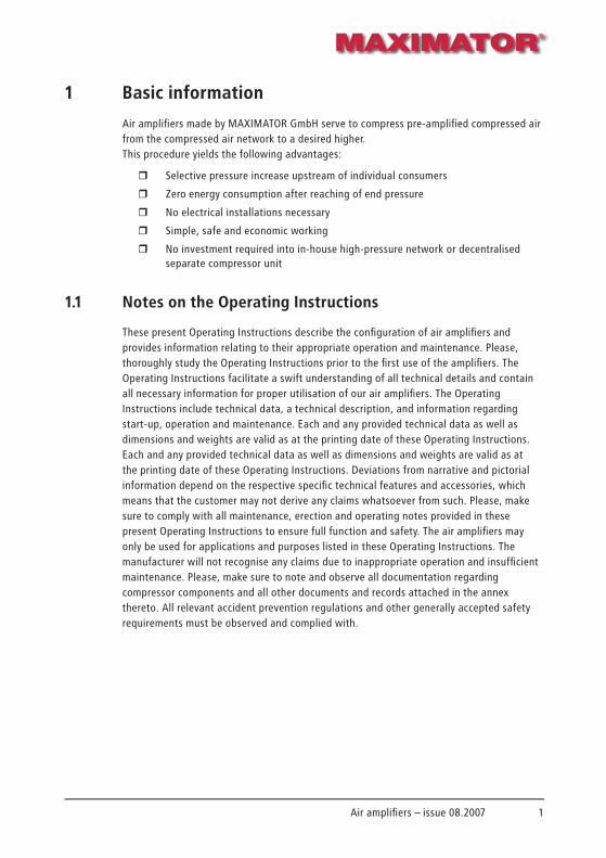
1 Basic information
Air amplifi ers made by MAXIMATOR GmbH serve to compress pre-amplifi ed compressed air from the compressed air network to a desired higher. This procedure yields the following advantages:
r Selective pressure increase upstream of individual consumers
r Zero energy consumption after reaching of end pressure
r No electrical installations necessary
r Simple, safe and economic working
r No investment required into in-house high-pressure network or decentralised separate compressor unit
1.1 Notes on the Operating Instructions
These present Operating Instructions describe the confi guration of air amplifi ers and provides information relating to their appropriate operation and maintenance. Please, thoroughly study the Operating Instructions prior to the fi rst use of the amplifi ers. The Operating Instructions facilitate a swift understanding of all technical details and contain all necessary information for proper utilisation of our air amplifi ers. The Operating Instructions include technical data, a technical description, and information regarding start-up, operation and maintenance. Each and any provided technical data as well as dimensions and weights are valid as at the printing date of these Operating Instructions. Each and any provided technical data as well as dimensions and weights are valid as at the printing date of these Operating Instructions. Deviations from narrative and pictorial information depend on the respective specifi c technical features and accessories, which means that the customer may not derive any claims whatsoever from such. Please, make sure to comply with all maintenance, erection and operating notes provided in these present Operating Instructions to ensure full function and safety. The air amplifi ers may only be used for applications and purposes listed in these Operating Instructions. The manufacturer will not recognise any claims due to inappropriate operation and insuffi cient maintenance. Please, make sure to note and observe all documentation regarding compressor components and all other documents and records attached in the annex thereto. All relevant accident prevention regulations and other generally accepted safety requirements must be observed and complied with.

2 Air amplifi ers – issue 08.2007
1.2 Use to the intended purpose
Air amplifi ers are exclusively employed in compressed air networks in order to compress pre-amplifi ed compressed air to a desired end pressure. The drives of our amplifi ers are rated for compressed air up to 10 bars. Changes at, and modifi cations of, air amplifi ers are not permitted for safety reasons. Please, make sure to comply with all maintenance, erection and operating notes provided in these present Operating Instructions to ensure full function and safety.Please, consult MAXIMATOR GmbH if you intend use other gases than compressed air.
1.3 Warranty and liability
As a rule, the „General Conditions of Sale and Delivery“ provided by the air amplifi er manufacturer are valid.
Warranty and liability claims in case of personnel injury and/or property damage shall be excluded when such are attributable to one or more of the below causes
r Use of an air amplifi er to other than the intended purpose.
r Inappropriate start-up, operation and/or maintenance of air amplifi ers.
r Changes at air amplifi ers
r Operation of an air amplifi er with defective safety installations improperly mounted safety and protection installations.
r Non-observance of notes and advices given in these Operating Instructions regarding compressor start-up, operation and maintenance.
r Insuffi cient monitoring of parts that are subject to wear and tear.
r Inappropriate repair work.
3Air amplifi ers – issue 08.2007
2 Safety notes
2.1 General safety directives
Safety of the machines is governed by the below EC Directives:
r Directive 89/655/EEC
r Accident prevention regulations VSG 1.1, VSG 3.1
r Machine Directive Annex II A, Paragraph 98/37/EC:
as well as the applied harmonised standards
r EN 60204-1
r EN ISO 12100-1 and 12100-2, EN 294, EN 349, EN 60204, EN 418, EN 693, EN 574
r Accident prevention regulations of German Employers’ Liability Insurance Association [Berufsgenossenschaft]
Air amplifi ers may emanate hazards when used by non-skilled personnel, inappropriately or for any other than the intended purpose. Every person that is ordered to operate or maintain the air amplifi ers must have read and understood the complete Operating Instructions prior to carrying out any of such operations. This applies also when the person already with the air amplifi ers or received training on compressors. The owner is advised to request its personnel to verify perusal of the contents of these Operating Instructions in writing. Knowledge of the contents of the Operating Instructions is one prerequisite to protect operatives from hazards as well as avoid faults and thus operate the air amplifi ers safe and without disturbances or malfunctions. The Operating Instructions shall be accessible to operating and maintenance personnel at any time! Responsibility for accident-free operation of compressors is the owner or its authorised personnel that is employed in operating or maintaining the air amplifi ers.All notes regarding labour safety refer to the currently valid regulations in the European Community. The applicable laws and national regulations have to be kept in other countries both in the European Community and in non-EU countries, the owner is obliged to determine the present status of codes and regulations. Both in the European Community and in non-EU countries, the owner is obliged to determine the present status of codes and regulations. Beside the labour safety notes in these Operating Instructions, the generally valid safety and accident prevention regulations must be observed and complied with.
All information provided in these Operating Instructions has to be observed without any restrictions!

4 Air amplifi ers – issue 08.2007
2.2 Symbols and signal words
HAZARD
Types and sources of hazards that may result in personal injuries or property damage.Measures to avert such hazards.
CAUTION
Types and sources of hazards that may result in personal injuries or property damage.Measures to avert such hazards.
NOTE
Advice for users and useful information.
NOTE
Environmental impacts
2.3 Fundamental Safety measures
2.3.1 Technical condition
Please, observe the following:
r In order to avoid hazards and ensure optimal performance, do not carry out any changes or modifi cations at the air amplifi ers. The user is obliged to operate the air amplifi ers in an appropriate and safe operating condition. The technical condition must conform to all statutory requirements and regulations
r The user is obliged to operate the air amplifi ers in an appropriate and safe operating condition. The technical condition must conform to all statutory requirements and regulations.
r Inspect the air amplifi ers prior to each start-up for damage and appropriate condition.
r Any changes at the air amplifi ers that have an impact on their safety have to be reported by personnel at once to the owner.

5Air amplifi ers – issue 08.2007
2.3.2 Safety notes relating to compressor operation
Check the air amplifi ers for operating safety prior to each start-up!
Observe the following safety notes during compressor operation:
r All generally valid safety and accident prevention regulations have to be observed!
r Make sure to know all installations, actuators and controls as well as their functions prior to starting the air amplifi ers!
r Make sure during the entire operation that on-site conditions are conducive to the application of the air amplifi ers.
r Stop the air amplifi ers at once when any changes are noticed during their operation.
CAUTION
Make sure to depressurise the air amplifi ers prior to starting any work on the units.
CAUTION
Setting and repair work may only be carried out by certifi ed workshops!
2.3.3 Safety notes relating to maintenance and repair
Operating disturbances that are caused by insuffi cient or inappropriate maintenance may result in very high repair costs and long downtimes of the air amplifi ers.The manufacturer will not assume any liability for damage that is due to inappropriate maintenance and care!Required maintenance intervals are specifi ed in a maintenance schedule.
Please, observe the following:
r The air amplifi ers may only be serviced, maintained and repaired by service personnel of the manufacturer or specifi cally trained and instructed skilled personnel.
r Each and any maintenance and repair work at the air amplifi ers may only be carried out when the compressors have been switched off and depressurised

6 Air amplifi ers – issue 08.2007
2.3.4 Requirements to owner’s personnel
r The hazards that may emanate from the air amplifi ers have to be pointed out to personnel before starting any work.
r Hazards of injury may emanate from the air amplifi ers when not operated by properly skilled persons.
r Each person that is instructed to start up, maintain or repair the air amplifi ers must have completely read and understood these Operating Instructions.
r The Operating Instructions must be accessible to the personnel at any time. It is recommended that taking note of the contents of the Operating Instructions be documented in writing.
r Upon instruction of the owner personnel has to wear protective clothing.
r All Safety notes in these Operating Instructions and in all pertaining documents must be observed and complied with at any time and without any restrictions.
r An air amplifi er has to be immediately switched off when hazards are detected that may result in personal injury.
r Personnel must have well-founded knowledge of the following operational sequences, in-house regulations and behaviours:
− Operating sequences of the air amplifi ers
− Limitation, safeguarding and marking of hazard zones
− Behaviour and measures in cases of hazards or emergency
2.4 Specifi c safety notes
2.4.1 Safety in case of emissions
Depending on the specifi c type of application, expanding compressed air will generate a certain noise level. air leaving the silencer may be soiled. It is also possible that small ice crystals form at the silencer that may come loose and hurl away. Persons near running air amplifi ers may have to wear protective goggles and, as the case may be, ear protection.
7Air amplifi ers – issue 08.2007
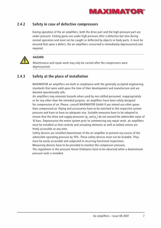
2.4.2 Safety in case of defective compressors
During operation of the air amplifi ers, both the drive part and the high-pressure part are under pressure. Exiting gases are under high pressure after a defective but also during normal operation and must not be caught or defl ected by objects or body parts. It must be ensured that upon a defect, the air amplifi ers concerned is immediately depressurised and repaired.
HAZARD
Maintenance and repair work may only be carried after the compressors were depressurised.
2.4.3 Safety at the place of installation
MAXIMATOR air amplifi ers are built in compliance with the generally accepted engineering standards that were valid upon the time of their development and manufacture and are deemed operationally safe.Air amplifi ers may emanate hazards when used by non-skilled personnel, inappropriately or for any other than the intended purpose. air amplifi ers have been solely designed for compression of air. Please, consult MAXIMATOR GmbH if you intend use other gases than compressed air. Piping and accessories have to be matched to the respective system pressure and have to have an adequate size. Suitable measures have to be adopted to ensure that the drive and supply pressures (pL and pa) do not exceed the admissible value of 10 bars. Depressurise the entire system prior to commencing any repair work. air amplifi ers must be installed so that controls and actuating elements as well as bolted unions are freely accessible at any time.Safety devices are installed downstream of the air amplifi er to prevent any excess of the admissible operating pressure by 10%. These safety devices must not be lockable. They must be easily accessible and subjected to recurring functional inspections. Measuring devices have to be provided to monitor the compressor pressure. The regulations in the pressure Vessel Ordinance have to be observed when a downstream pressure tank is installed.

8 Air amplifi ers – issue 08.2007
9Air amplifi ers – issue 08.2007
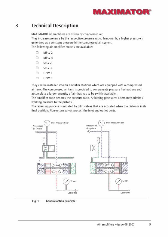
3 Technical Description
MAXIMATOR air amplifi ers are driven by compressed air. They increase pressure by the respective pressure ratio. Temporarily, a higher pressure is generated at a constant pressure in the compressed air system. The following air amplifi er models are available:
r MPLV 2
r MPLV 4
r SPLV 2
r SPLV 3
r GPLV 2
r GPLV 5
They can be installed into air amplifi er stations which are equipped with a compressed air tank. The compressed air tank is provided to compensate pressure fl uctuations and accumulate a larger quantity of air that has to be swiftly available.The amplifi er code denotes the pressure ratio. A fl oating gate valve alternately admits a working pressure to the pistons. The reversing process is initiated by pilot valves that are actuated when the piston is in its fi nal position. Non-return valves protect the inlet and outlet ports.
6 barbar
6 barbar
6 barbar
6 barbar
6 bar
6 bar
6 bar
6 bar
12 bar
Pressurised air system
Inlet Pressure 6 bar
Consumer
Fig. 1: General action principle
6 barbar
6 barbar
6 barbar
6 barbar
6 bar
6 bar
6 bar
6 bar
12 bar
Pressurised air system
Inlet Pressure 6 bar
Consumer

10 Air amplifi ers – issue 08.2007
3.1 Functioning of the air amplifi ers
3.1.1 Air amplifi ers MPLV 4 and MPLV 4L
The feeding pressure fi lls the compression space from Port A. The drive space is not charged with pressure, hence the piston evades until actuates the pilot valve in the top cap. Now drive air from Port PL fl ows through the main block valve and gets into the drive space. Thus, air in the compression space is compressed and conveyed to the pressure outlet (Port B). When the piston actuates the pilot valve in the bottom cap, the infl ow of air into the drive space is interrupted and the process begins anew. The pressure increase is due to the fourfold larger surface area of the piston in the drive space in comparison to the piston in the compression space.
Example:
Drive pressure = 6 bars
Pressure ratio = 1:4
Operating pressure = 6 x 4 = 24 bars
Fig. 2: Functioning of MPLV 4
1 Pressure outlet2 Feeding pressure3 Compression space4 Pilot valve
5 Pilot valve6 Drive space7 Servo-valve8 Exhaust
PL = Drive pressureB = pressure outletY2 = Exhaust air from pilot valve
A = Feeding pressureY1 = Exhaust air from
control valve
11Air amplifi ers – issue 08.2007
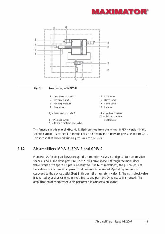
Fig. 3: Functioning of MPLV 4L
1 Compression space2 Pressure outlet3 Feeding pressure4 Pilot valve
5 Pilot valve6 Drive space7 Servo-valve8 Exhaust
PL = Drive pressure Tab. 1:
B = Pressure outletY2 = Exhaust air from pilot valve
A = Feeding pressureY1 = Exhaust air from
control valve
The function in this model MPLV 4L is distinguished from the normal MPLV 4 version in the „suction stroke“ is carried out through drive air and by the admission pressure at Port „A“. This means that lower admission pressures can be used.
3.1.2 Air amplifi ers MPLV 2, SPLV 2 and GPLV 2
From Port A, feeding air fl ows through the non-return valves 2 and gets into compression spaces I and II. The drive pressure (Port PL) fi lls drive space II through the main block valve, while drive space I is pressure-relieved. Due to its movement, the piston reduces the volume of compression space II and pressure is increased. Operating pressure is conveyed to the device outlet (Port B) through the non-return valve 4. The main block valve is reversed by a pilot valve upon reaching its end position. Drive space II is vented. The amplifi cation of compressed air is performed in compression space I.

12 Air amplifi ers – issue 08.2007
In air amplifi ers fi tted with a Port X, control air is charged from an external source. Control air is branched off from drive compressed air (upstream of pressure reduction) and charged through pipes to Port X. A directional control valve in the control pipe can be used to the air amplifi ers on and off.
Example:
Drive space II = 4 bars
+ Compression space I = 4 bars
Compression space II = 8 bars
Fig. 4: Functioning of MPLV 2, SPLV2, GPLV2
1 Compression space II2 Non-return valves inlet3 Drive space II4 Non-return valves outlet5 Pilot valve
6 Pilot valve7 Drive space I8 + Compression space I9 Servo-valve10 Exhaust
PL = Drive pressure:B = pressure outletY2 = Exhaust air from pilot valve
A = Feeding pressureY1 = Exhaust air from control
valveX = Control pipe
(possible external port for control pipe)
13Air amplifi ers – issue 08.2007
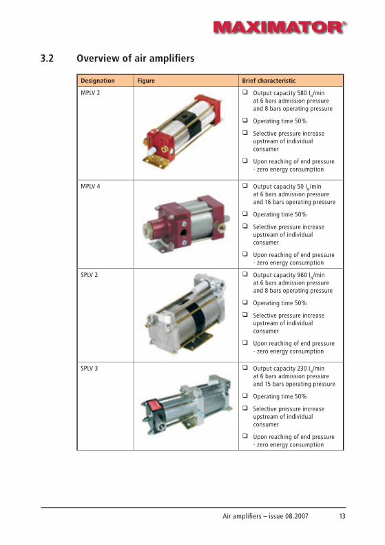
3.2 Overview of air amplifi ers
Designation Figure Brief characteristic
MPLV 2 q Output capacity 580 IN/min at 6 bars admission pressure and 8 bars operating pressure
q Operating time 50%
q Selective pressure increase upstream of individual consumer
q Upon reaching of end pressure - zero energy consumption
MPLV 4 q Output capacity 50 IN/min at 6 bars admission pressure and 16 bars operating pressure
q Operating time 50%
q Selective pressure increase upstream of individual consumer
q Upon reaching of end pressure - zero energy consumption
SPLV 2 q Output capacity 960 IN/min at 6 bars admission pressure and 8 bars operating pressure
q Operating time 50%
q Selective pressure increase upstream of individual consumer
q Upon reaching of end pressure - zero energy consumption
SPLV 3 q Output capacity 230 IN/min at 6 bars admission pressure and 15 bars operating pressure
q Operating time 50%
q Selective pressure increase upstream of individual consumer
q Upon reaching of end pressure - zero energy consumption
14 Air amplifi ers – issue 08.2007
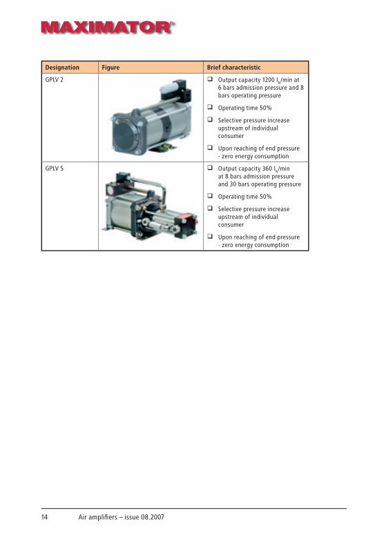
Designation Figure Brief characteristic
GPLV 2 q Output capacity 1200 IN/min at 6 bars admission pressure and 8 bars operating pressure
q Operating time 50%
q Selective pressure increase upstream of individual consumer
q Upon reaching of end pressure - zero energy consumption
GPLV 5 q Output capacity 360 IN/min at 8 bars admission pressure and 30 bars operating pressure
q Operating time 50%
q Selective pressure increase upstream of individual consumer
q Upon reaching of end pressure - zero energy consumption

15Air amplifi ers – issue 08.2007
4 Erection and start-up
4.1 General notes on erection at place of application
Our air amplifi ers can be installed in any desired position. Fixing angles are provided for fastening the air amplifi ers. Make sure to avoid ingress of any foreign matter into the air amplifi ers ports during erection (e.g. drilling dust during wall mounting). Remove the blind plugs from air amplifi ers ports only just prior to fastening the respective ports.
NOTE
Make sure to apply always the same torque (8 Nm) on stud bolts and nuts when mounting air amplifi ers to prevent distortion of the top and bottom parts of air amplifi ers.
4.2 Compressed air system
The compressed-air port requires mounting of a compressed air control unit made by MAXIMATOR downstream of the air amplifi ers. The compressed air control unit consists of pressure fi lter, water separator, shut-off valve, pressure controller, pressure gauge and, if need be, safety valve.
Fig. 5: Compressed air control unit
If there is no compressed air control unit installed, the specifi ed compressed air quality for the air amplifi er has to be ensured according to the requirements of the manufacturer.
16 Air amplifi ers – issue 08.2007
Requirements to compressed air quality:
r Solid matter Maximum particle size 5 µm Maximum particle concentration 5 mg/m3
r Dew point Up to +10 °C, water content of 9.4 g/m3 Up to + 2 °C, water content of 5.6 g/m3
r Oil content 1.0 to 5 mg/m3
4.2.1 Compressed air lubrifi cator
A compressed air lubrifi cator is not necessarily required. All moving air amplifi ers parts are treated with special grease during erection. The grease may become gummy when the air amplifi er is operated with extremely dry air for a longer period of time. Use of a compressed air lubrifi cator is recommended in such cases.
CAUTION
After use of a compressed air lubrifi cator the air amplifi ers must never be operated without this oiler. The oil of the compressed air lubrifi cator purges grease from the air amplifi ers so that permanent lubrication cannot be ensured. Special grease made by the MAXIMATOR GmbH may be used for re-lubrication. When employing a compressed air lubrifi cator, the oil content of compressed air should be 1 mg/m3 to 5 mg/m3.
4.2.2 Pipe cross sections
The compressed air port must not be specifi ed smaller than the port thread. Reduction to smaller port threads may result in performance losses and malfunctions of the air amplifi ers. Excessively long supply pipes may give rise to problems due to pressure drop in smaller pipes.
17Air amplifi ers – issue 08.2007
4.3 High-pressure system
The employed HP pipes and accessories parts must be matched to the air amplifi ers as regards pressure and cross sections. Otherwise the performance capacity and safety of the air amplifi ers may be impaired.
4.3.1 Pressure pipe
The pressure pipe and the pertaining accessories must withstand the maximum outlet pressure of the air amplifi ers. The pressure strength may only be fallen short of when an adequate safety valve is installed in the pressure pipe. The cross section of the pressure pipe must not be smaller than that of the pressure port. A smaller cross section will reduce output capacity and lead to higher warming of the compressor.
4.3.2 Compressor medium
The air amplifi ers may only be used for compressed air. Any other media have to be tested before utilisation by MAXIMATOR GmbH for compatibility with the air amplifi er materials.
4.4 Start-up
As in a normal piston-type compressor, there occur pressure pulsations in air amplifi ers due to the stroke frequency. Such pressure pulsations can be reduced by providing an additional volume (e.g. a pressure tank). The fi lling time of the additional volume downstream of the air amplifi er can be reduced by means of a bypass pipe. This means that the air amplifi er is bypassed by a pipe with non-return valve that is branched off directly from the compressed air port. The air amplifi er only starts to increase pressure when the operating pressure pb is equal to the inlet pressure pa. Air amplifi ers with external control air are equipped with a port marked „X“ (also possible for SPLV 2 and GPLV 2). This pipe that is branched off from inlet pressure can be used for installation of a pressure switch.

18 Air amplifi ers – issue 08.2007
Connection options for air amplifi ers:
1. Control of operating pressure pb by reduction of drive pressure pl. Larger pressure fl uctuations in the compressed air network make an impact on operating pressure. Pressure reduction will decrease output capacity.
2. Direct control of operating pressure pb by pressure reducer valve. Good control of operating pressure at highest output capacity. Pressure fl uctuations in the compressed air network do not make an impact on operating pressure (external control port).
3. Use of a pressure switch NO (normally open, only possible in SPLV 2 and GPLV 2).Drive air fl ows through the bypass pipe to pressure outlet until the same pressure is achieved. A larger volume can be faster fi lled on the pressure outlet side. The air amplifi er operates until the operating pressure set at the pressure switch NO has been reached. This connection option is only reasonable when there is no continuous compressed air consumption.
4. Use of a pressure switch NC (normally shut, only possible in SPLV 2 and GPLV 2). The pressure switch NC has to be set to a lower pressure than the drive pressure. Air fl ows through the bypass pipe as long as the operating pressure is lower than the set pressure. The air amplifi er does not yet operate under these circumstances. The air amplifi er only starts to work when the operating pressure has reached the set value. Wearing of sealings can be reduced with this switching set-up.

19Air amplifi ers – issue 08.2007
5 Maintenance and servicing
5.1 Maintenance notes
The air drives of all air amplifi ers are pre-treated with high-performances grease during erection and require no other form of lubrication During maintenance and servicing work of the air amplifi ers, the servo-valves and air pistons shall be treated with an acid- and silicon-free high-performances grease provided by the manufacturing company. A compressed air oiler has to be installed upstream of the air amplifi er at a stroke frequency of >= 150 strokes/min or an operating time of > 50 %.
5.2 Servicing
NOTE
Use only original MAXIMATOR spare parts when repairing.
NOTE
Exercise and observe utmost cleanliness during serving and repair of air amplifi ers to ensure proper functioning and longevity of the precision-machined parts.
Possible fault Cause of fault Fault removal
Air amplifi er fails to run at low air pressure.
Friction of O-rings on servo-valve is too high.
q Re-lubricate.
q Replace O-rings on servo-valve.
Air amplifi er fails to run or operates only slowly.
Exhaust or servo-valve covered with ice.
q Dewater compressed air with water separator.
Formation of residue in the silencer.
q Clean the silencers.
q Replace, if need be.
Air amplifi er fails to run. Air escapes through the exhaust.
O-rings at servo-valve are defective.
q Change and grease O-rings.
O-ring at air piston is defective or worn out.
q Change and grease q O-rings.

20 Air amplifi ers – issue 08.2007
Possible fault Cause of fault Fault removal
Air amplifi er does not work.Air fl ows through small boring at housing of main block valve.
Servo-valve is hung up. q Clean servo-valve and sleeve.
q Check O-rings and sleeve and replace, if need be.Lubricate.
Air amplifi er does not work.Air fl ows through small boring at servo-valve housing.
Pilot valve in top or bottom cap is hung up.
q Clean and grease pilot valve.
q Replace pilot valve, if need be. Clean servo-valve and sleeve.
Air amplifi er runs with high frequency and short strokes.
Pilot valve in top or bottom cap is hung up.
q Clean and grease pilot valve.
q Replace pilot valve, if need be
Air amplifi er fails to reach its arithmetic end pressure.
Sealings on air pistons are worn out.
q Replace and grease sealings.
Failure of non-return valves. q Check and clean non-return valves.
q Replace non-return valves, if need be.
Only applicable to MPLV 4, SPLV3 and GPLV 5Air amplifi ers fails to reach end pressure.
Leakage in HP sealing. q Replace HP sealing.
Only applicable to MPLV 4, SPLV3 and GPLV 5Air amplifi er does not stop.
Admission pressure too low. q Increase admission pressure.
5.3 Repair
NOTE
Repair instructions for the air amplifi ers can be found on the Internet at www.maximator.de.
CAUTION
Repair work has to be carried out by qualifi ed skilled operatives. Make sure to observe absolute cleanliness. Make sure to observe absolute cleanliness. Minor impurities may cause serious damage at precision-machined compressor components.

21Air amplifi ers – issue 08.2007
Individual parts of the air amplifi ers can be ordered as spare parts from MAXIMATOR Sealings are subject to high wear and tear. The order numbers and compositions of sealing kits in indicated in the respective drawing. Said drawing is part of each air amplifi er documentation and is enclosed to the packaging of the air amplifi ers. Please, quote the serial number of the air amplifi er when ordering spare parts. The serial number (a 6-digit number) is located on the machine plate and the compressor housing.
NOTE
You can ship defective air amplifi ers for repair to MAXIMATORAll repair work is conducted by qualifi ed personnel in clean rooms.
5.3.1 Liability for material defects
For air amplifi ers, manufacturer grants a warranty of twelve (12) months on material quality and workmanship. Said warranty commences on the air amplifi er shipment date.
This warranty does not cover defects caused by application of inadmissible medias and foreign matter in the drive or media. This shall also apply to excision of maximum operating pressure. This warranty does also not apply to damage resulting from normal wear and tear (wear parts, such as sealings, guiding elements, etc.), improper operation and inadequate maintenance.

22 Air amplifi ers – issue 08.2007

23Air amplifi ers – issue 08.2007
6 Technical data
Technical data MPLV 2 MPLV 4 SPLV 2 SPLV 3 GPLV 2 GPLV 5
Pressure ratio 1:2 1:4 1:2 1:3,2 1:2 1:5
Air drive pressure in bar 1-10 2-10 1-10 1-10 1-10 1-10
Max. operating pressure in bar 20 40 20 32 20 60
Max. noise level in dB 79 79 79 79 79 79
Max. operating temperature in °C 60 60 60 60 60 60
Port: Air drive pressure G 3/8“ G 3/8“ G 1/2“ G 1/2“ G 3/4“ G 1/2“
Port: Pressure inlet G 3/8“ G 3/8“ G 1/2“ G 1/2“ G 1/2“ G 3/8“
Port: Pressure outlet G 3/8“ G 1/2“ G 1/2“ G 1/2“ G 1/2“ G 3/8“
Weight 3.3 2.2 16.0 8.5 20.5 16.0

• Hochdruck-Pumpen für verschiedene Flüssigkeiten (Öl, Wasser, Emulsion usw.)
• High-pressure pumps for different liquids (oil, water, emulsion etc.)
• Pompes haute pression pour differents fl uides
• Druckluft-Erhöher
• Compressed Air Amplifi ers
• Surpresseurs d‘air comprimé
• Gasinnendruck-Technik
• Gas Assist Injektion Systems
• Technique de gaz sous pression
• Prüfstände für Druckprüfungen, Berst- druckprüfungen und Impulsprüfungen
• Special Test Benches
• Bancs d‘essai spéciaux
• Ventile, Rohre, Armaturen für die Hochdruck-Technik
• High Pressure Valves, Fittings, Tubing
• Vannes, tubes, raccords pour techniques haute pression
MAXIMATOR® GmbHWalkenrieder Straße 15 • D-37449 ZorgeFon +49 (0) 55 86 / 80 30 • Fax +49 (0) 55 86 / 8 03-30 40eMail: [email protected] • Internet: www.maximator.de
MAXIMATOR®MAXIMATOR®39
99.0
862
| 100
0 D
SB