
Operating Instructions, Absolute encoders with PROFINET IO · Absolute encoders with PROFINET IO 10...
102
SIMOTION/SIMATIC MC-ENCODER Absolute encoders with PROFINET IO Operating Instructions Valid for: Firmware Version SIMOTION 4.2 Product Version MC-ENCODER V1.0 06/2015 6SN1197-0AB11-0BP1 Preface Fundamental safety instructions for SINAMICS hardware and software documentation 1 Introduction 2 Installing 3 Cyclic Data Exchange 4 Configuration 5 Operating with STEP7 6 Operating with SIMOTION 7 Troubleshooting/FAQs 8 Technical Data 9 Mechanical Drawings 10 Accessories 11 Appendix A
-
Upload
phungnguyet -
Category
Documents
-
view
226 -
download
0
Transcript of Operating Instructions, Absolute encoders with PROFINET IO · Absolute encoders with PROFINET IO 10...

SIMOTION/SIMATIC
MC-ENCODERAbsolute encoders with PROFINET IO
Operating Instructions
Valid for:Firmware Version SIMOTION 4.2 ProductVersion MC-ENCODER V1.0
06/20156SN1197-0AB11-0BP1
Preface
Fundamental safety instructions for SINAMICS hardware and software documentation
1
Introduction 2
Installing 3
Cyclic Data Exchange 4
Configuration 5
Operating with STEP7 6
Operating with SIMOTION 7
Troubleshooting/FAQs 8
Technical Data 9
Mechanical Drawings 10
Accessories 11
Appendix A
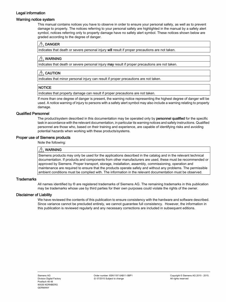
Legal informationWarning notice system
This manual contains notices you have to observe in order to ensure your personal safety, as well as to prevent damage to property. The notices referring to your personal safety are highlighted in the manual by a safety alert symbol, notices referring only to property damage have no safety alert symbol. These notices shown below are graded according to the degree of danger.
DANGERindicates that death or severe personal injury will result if proper precautions are not taken.
WARNINGindicates that death or severe personal injury may result if proper precautions are not taken.
CAUTIONindicates that minor personal injury can result if proper precautions are not taken.
NOTICEindicates that property damage can result if proper precautions are not taken.If more than one degree of danger is present, the warning notice representing the highest degree of danger will be used. A notice warning of injury to persons with a safety alert symbol may also include a warning relating to property damage.
Qualified PersonnelThe product/system described in this documentation may be operated only by personnel qualified for the specific task in accordance with the relevant documentation, in particular its warning notices and safety instructions. Qualified personnel are those who, based on their training and experience, are capable of identifying risks and avoiding potential hazards when working with these products/systems.
Proper use of Siemens productsNote the following:
WARNINGSiemens products may only be used for the applications described in the catalog and in the relevant technical documentation. If products and components from other manufacturers are used, these must be recommended or approved by Siemens. Proper transport, storage, installation, assembly, commissioning, operation and maintenance are required to ensure that the products operate safely and without any problems. The permissible ambient conditions must be complied with. The information in the relevant documentation must be observed.
TrademarksAll names identified by ® are registered trademarks of Siemens AG. The remaining trademarks in this publication may be trademarks whose use by third parties for their own purposes could violate the rights of the owner.
Disclaimer of LiabilityWe have reviewed the contents of this publication to ensure consistency with the hardware and software described. Since variance cannot be precluded entirely, we cannot guarantee full consistency. However, the information in this publication is reviewed regularly and any necessary corrections are included in subsequent editions.
Siemens AGDivision Digital FactoryPostfach 48 4890026 NÜRNBERGGERMANY
Order number: 6SN1197-0AB11-0BP1Ⓟ 07/2015 Subject to change
Copyright © Siemens AG 2010 - 2015.All rights reserved
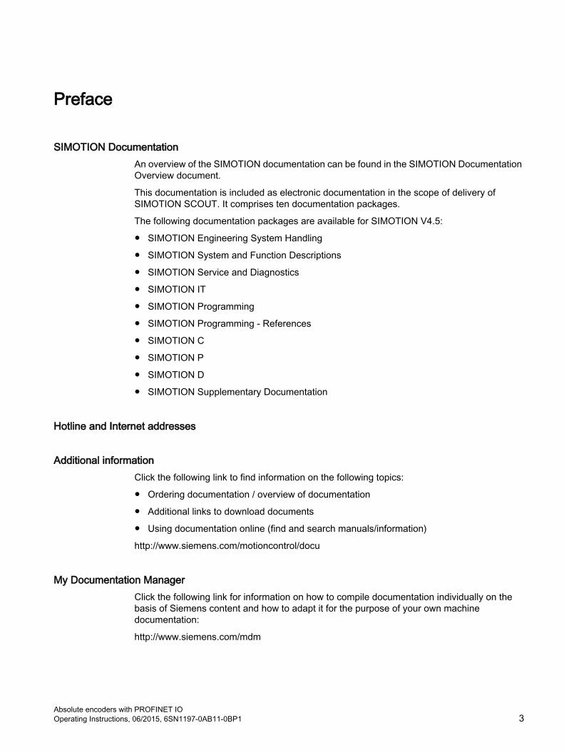
Preface
SIMOTION DocumentationAn overview of the SIMOTION documentation can be found in the SIMOTION Documentation Overview document.
This documentation is included as electronic documentation in the scope of delivery of SIMOTION SCOUT. It comprises ten documentation packages.
The following documentation packages are available for SIMOTION V4.5:
● SIMOTION Engineering System Handling
● SIMOTION System and Function Descriptions
● SIMOTION Service and Diagnostics
● SIMOTION IT
● SIMOTION Programming
● SIMOTION Programming - References
● SIMOTION C
● SIMOTION P
● SIMOTION D
● SIMOTION Supplementary Documentation
Hotline and Internet addresses
Additional informationClick the following link to find information on the following topics:
● Ordering documentation / overview of documentation
● Additional links to download documents
● Using documentation online (find and search manuals/information)
http://www.siemens.com/motioncontrol/docu
My Documentation ManagerClick the following link for information on how to compile documentation individually on the basis of Siemens content and how to adapt it for the purpose of your own machine documentation:
http://www.siemens.com/mdm
Absolute encoders with PROFINET IO Operating Instructions, 06/2015, 6SN1197-0AB11-0BP1 3

TrainingClick the following link for information on SITRAIN - Siemens training courses for automation products, systems and solutions:
http://www.siemens.com/sitrain
FAQsFrequently Asked Questions can be found in SIMOTION Utilities & Applications, which are included in the scope of delivery of SIMOTION SCOUT, and in the Service&Support pages in Product Support:
http://support.automation.siemens.com
Technical supportCountry-specific telephone numbers for technical support are provided on the Internet under Contact:
http://www.siemens.com/automation/service&support
Preface
Absolute encoders with PROFINET IO 4 Operating Instructions, 06/2015, 6SN1197-0AB11-0BP1

Table of contents
Preface.........................................................................................................................................................3
1 Fundamental safety instructions for SINAMICS hardware and software documentation.............................9
1.1 Fundamental safety instructions..............................................................................................91.1.1 General safety instructions.......................................................................................................91.1.2 Safety instructions for electromagnetic fields (EMF)..............................................................131.1.3 Handling electrostatic sensitive devices (ESD)......................................................................131.1.4 Industrial security...................................................................................................................141.1.5 Residual risks of power drive systems...................................................................................14
2 Introduction.................................................................................................................................................17
2.1 Absolute encoder...................................................................................................................18
2.2 PROFINET technology...........................................................................................................19
2.3 Encoder profile.......................................................................................................................20
2.4 Features of the MC-ENCODER.............................................................................................21
2.5 Encoder functions..................................................................................................................22
3 Installing ....................................................................................................................................................23
3.1 Electrical connection..............................................................................................................23
3.2 Ethernet cables......................................................................................................................25
3.3 Diagnostic LEDs.....................................................................................................................26
3.4 Status LED indication.............................................................................................................27
3.5 Instructions for mechanical installation and electrical connection of the encoder..................28
4 Cyclic Data Exchange................................................................................................................................29
4.1 Signal list for cyclic data transmission....................................................................................30
4.2 Format of actual position values G1_X..................................................................................314.2.1 G1_XIST1...............................................................................................................................314.2.2 G1_XIST2...............................................................................................................................324.2.3 G1_XIST3...............................................................................................................................334.2.4 G1_XIST_PRESET_A............................................................................................................33
4.3 Format of actual velocity values NIST....................................................................................34
4.4 Encoder control word (STW2_ENC)......................................................................................35
4.5 Encoder status word (ZSW2_ENC)........................................................................................36
4.6 Sensor control word (G1_STW).............................................................................................37
4.7 Sensor status word (G1_ZSW)..............................................................................................38
4.8 Telegrams..............................................................................................................................394.8.1 Standard telegram 81.............................................................................................................394.8.2 Standard telegram 82.............................................................................................................39
Absolute encoders with PROFINET IO Operating Instructions, 06/2015, 6SN1197-0AB11-0BP1 5
4.8.3 Standard telegram 83.............................................................................................................404.8.4 Standard telegram 84.............................................................................................................404.8.5 Telegram 860.........................................................................................................................41
5 Configuration..............................................................................................................................................43
5.1 Encoder configuration overview.............................................................................................44
5.2 Encoder offline configuration..................................................................................................45
5.3 Encoder parameter description..............................................................................................475.3.1 Encoder parameter................................................................................................................475.3.2 Parameterizing the position actual value...............................................................................475.3.3 Parameterizing the scaling function.......................................................................................485.3.4 Parameterizing the velocity signal..........................................................................................495.3.5 Parameterizing the communication interface.........................................................................49
6 Operating with STEP7................................................................................................................................53
6.1 Installing the GSDML file........................................................................................................54
6.2 Engineering the MC-ENCODER in a STEP7 project.............................................................55
6.3 LLDP (Link Layer Discovery Protocol)...................................................................................59
6.4 Selecting the MC-ENCODER telegram..................................................................................62
6.5 Setting encoder parameters...................................................................................................63
6.6 Setting device properties........................................................................................................64
6.7 IRT settings............................................................................................................................66
6.8 Changing and reading encoder parameters during the run-time...........................................67
6.9 Accessing cyclic data.............................................................................................................68
7 Operating with SIMOTION..........................................................................................................................69
7.1 Applications............................................................................................................................70
7.2 MC-ENCODER used together with TO External encoder......................................................71
7.3 MC-ENCODER used directly from AWP................................................................................81
7.4 Online parameter access.......................................................................................................83
8 Troubleshooting/FAQs................................................................................................................................85
8.1 FAQ........................................................................................................................................85
9 Technical Data............................................................................................................................................87
9.1 Electrical data.........................................................................................................................87
9.2 Mechanical data.....................................................................................................................88
9.3 Environmental conditions.......................................................................................................89
10 Mechanical Drawings.................................................................................................................................91
10.1 Synchro flange.......................................................................................................................91
10.2 Clamp flange..........................................................................................................................92
10.3 Hollow shaft............................................................................................................................93
Table of contents
Absolute encoders with PROFINET IO 6 Operating Instructions, 06/2015, 6SN1197-0AB11-0BP1

11 Accessories................................................................................................................................................95
11.1 Accessories and Documentation............................................................................................95
11.2 Ordering description...............................................................................................................96
11.3 Models / ordering description.................................................................................................97
A Appendix.....................................................................................................................................................99
A.1 Glossary.................................................................................................................................99
A.2 Additional literature..............................................................................................................101
Index.........................................................................................................................................................103
Table of contents
Absolute encoders with PROFINET IO Operating Instructions, 06/2015, 6SN1197-0AB11-0BP1 7

Table of contents
Absolute encoders with PROFINET IO 8 Operating Instructions, 06/2015, 6SN1197-0AB11-0BP1

Fundamental safety instructions for SINAMICS hardware and software documentation 11.1 Fundamental safety instructions
1.1.1 General safety instructions
DANGER
Danger to life due to live parts and other energy sources
Death or serious injury can result when live parts are touched.● Only work on electrical devices when you are qualified for this job. ● Always observe the country-specific safety rules.
Generally, six steps apply when establishing safety: 1. Prepare for shutdown and notify all those who will be affected by the procedure.2. Disconnect the machine from the supply.
– Switch off the machine. – Wait until the discharge time specified on the warning labels has elapsed. – Check that it really is in a no-voltage condition, from phase conductor to phase
conductor and phase conductor to protective conductor.– Check whether the existing auxiliary supply circuits are de-energized.– Ensure that the motors cannot move.
3. Identify all other dangerous energy sources, e.g. compressed air, hydraulic systems, or water.
4. Isolate or neutralize all hazardous energy sources by closing switches, grounding or short-circuiting or closing valves, for example.
5. Secure the energy sources against switching on again. 6. Ensure that the correct machine is completely interlocked.
After you have completed the work, restore the operational readiness in the inverse sequence.
WARNING
Danger to life through a hazardous voltage when connecting an unsuitable power supply
Touching live components can result in death or severe injury. ● Only use power supplies that provide SELV (Safety Extra Low Voltage) or PELV-
(Protective Extra Low Voltage) output voltages for all connections and terminals of the electronics modules.
Absolute encoders with PROFINET IO Operating Instructions, 06/2015, 6SN1197-0AB11-0BP1 9

WARNING
Danger to life when live parts are touched on damaged devices
Improper handling of devices can cause damage.
For damaged devices, hazardous voltages can be present at the enclosure or at exposed components; if touched, this can result in death or severe injury. ● Ensure compliance with the limit values specified in the technical data during transport,
storage and operation. ● Do not use any damaged devices.
WARNING
Danger to life through electric shock due to unconnected cable shields
Hazardous touch voltages can occur through capacitive cross-coupling due to unconnected cable shields.● As a minimum, connect cable shields and the conductors of power cables that are not
used (e.g. brake cores) at one end at the grounded housing potential.
WARNING
Danger to life due to electric shock when not grounded
For missing or incorrectly implemented protective conductor connection for devices with protection class I, high voltages can be present at open, exposed parts, which when touched, can result in death or severe injury.● Ground the device in compliance with the applicable regulations.
WARNING
Danger to life due to electric shock when opening plug connections in operation
When opening plug connections in operation, arcs can result in severe injury or death.● Only open plug connections when the equipment is in a no-voltage state, unless it has
been explicitly stated that they can be opened in operation.
WARNING
Danger to life due to fire spreading if housing is inadequate
Fire and smoke development can cause severe personal injury or material damage. ● Install devices without a protective housing in a metal control cabinet (or protect the device
by another equivalent measure) in such a way that contact with fire is prevented.● Ensure that smoke can only escape via controlled and monitored paths.
Fundamental safety instructions for SINAMICS hardware and software documentation1.1 Fundamental safety instructions
Absolute encoders with PROFINET IO 10 Operating Instructions, 06/2015, 6SN1197-0AB11-0BP1

WARNING
Danger to life through unexpected movement of machines when using mobile wireless devices or mobile phones
Using mobile wireless devices or mobile phones with a transmit power > 1 W closer than approx. 2 m to the components may cause the devices to malfunction, influence the functional safety of machines therefore putting people at risk or causing material damage.● Switch the wireless devices or mobile phones off in the immediate vicinity of the
components.
WARNING
Danger to life due to the motor catching fire in the event of insulation overload
There is higher stress on the motor insulation through a ground fault in an IT system. If the insulation fails, it is possible that death or severe injury can occur as a result of smoke and fire. ● Use a monitoring device that signals an insulation fault. ● Correct the fault as quickly as possible so the motor insulation is not overloaded.
WARNING
Danger to life due to fire if overheating occurs because of insufficient ventilation clearances
Inadequate ventilation clearances can cause overheating of components with subsequent fire and smoke. This can cause severe injury or even death. This can also result in increased downtime and reduced service lives for devices/systems. ● Ensure compliance with the specified minimum clearance as ventilation clearance for the
respective component.
WARNING
Danger of an accident occurring due to missing or illegible warning labels
Missing or illegible warning labels can result in accidents involving death or serious injury. ● Check that the warning labels are complete based on the documentation.● Attach any missing warning labels to the components, in the national language if
necessary.● Replace illegible warning labels.
Fundamental safety instructions for SINAMICS hardware and software documentation1.1 Fundamental safety instructions
Absolute encoders with PROFINET IO Operating Instructions, 06/2015, 6SN1197-0AB11-0BP1 11
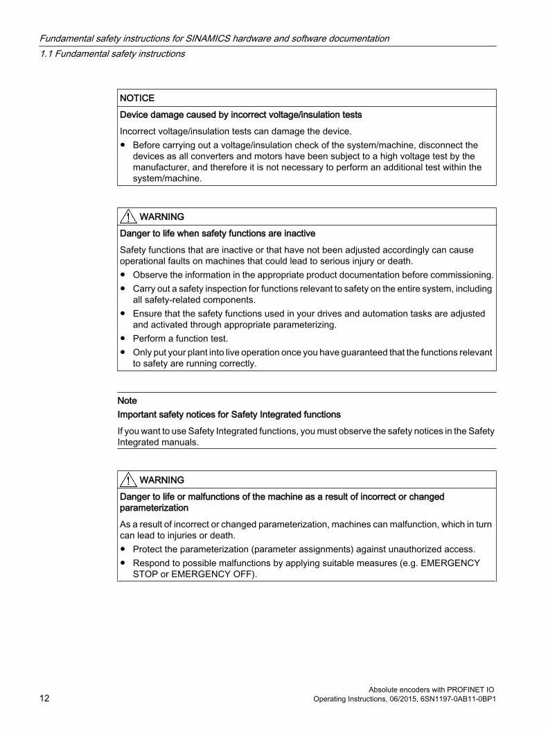
NOTICE
Device damage caused by incorrect voltage/insulation tests
Incorrect voltage/insulation tests can damage the device.● Before carrying out a voltage/insulation check of the system/machine, disconnect the
devices as all converters and motors have been subject to a high voltage test by the manufacturer, and therefore it is not necessary to perform an additional test within the system/machine.
WARNING
Danger to life when safety functions are inactive
Safety functions that are inactive or that have not been adjusted accordingly can cause operational faults on machines that could lead to serious injury or death. ● Observe the information in the appropriate product documentation before commissioning.● Carry out a safety inspection for functions relevant to safety on the entire system, including
all safety-related components.● Ensure that the safety functions used in your drives and automation tasks are adjusted
and activated through appropriate parameterizing. ● Perform a function test.● Only put your plant into live operation once you have guaranteed that the functions relevant
to safety are running correctly.
NoteImportant safety notices for Safety Integrated functions
If you want to use Safety Integrated functions, you must observe the safety notices in the Safety Integrated manuals.
WARNING
Danger to life or malfunctions of the machine as a result of incorrect or changed parameterization
As a result of incorrect or changed parameterization, machines can malfunction, which in turn can lead to injuries or death.● Protect the parameterization (parameter assignments) against unauthorized access.● Respond to possible malfunctions by applying suitable measures (e.g. EMERGENCY
STOP or EMERGENCY OFF).
Fundamental safety instructions for SINAMICS hardware and software documentation1.1 Fundamental safety instructions
Absolute encoders with PROFINET IO 12 Operating Instructions, 06/2015, 6SN1197-0AB11-0BP1

1.1.2 Safety instructions for electromagnetic fields (EMF)
WARNING
Danger to life from electromagnetic fields
Electromagnetic fields (EMF) are generated by the operation of electrical power equipment such as transformers, converters or motors.
People with pacemakers or implants are at a special risk in the immediate vicinity of these devices/systems.● Ensure that the persons involved are the necessary distance away (minimum 2 m).
1.1.3 Handling electrostatic sensitive devices (ESD)Electrostatic sensitive devices (ESD) are individual components, integrated circuits, modules or devices that may be damaged by either electric fields or electrostatic discharge.
NOTICE
Damage through electric fields or electrostatic discharge
Electric fields or electrostatic discharge can cause malfunctions through damaged individual components, integrated circuits, modules or devices.● Only pack, store, transport and send electronic components, modules or devices in their
original packaging or in other suitable materials, e.g conductive foam rubber of aluminum foil.
● Only touch components, modules and devices when you are grounded by one of the following methods:– Wearing an ESD wrist strap– Wearing ESD shoes or ESD grounding straps in ESD areas with conductive flooring
● Only place electronic components, modules or devices on conductive surfaces (table with ESD surface, conductive ESD foam, ESD packaging, ESD transport container).
Fundamental safety instructions for SINAMICS hardware and software documentation1.1 Fundamental safety instructions
Absolute encoders with PROFINET IO Operating Instructions, 06/2015, 6SN1197-0AB11-0BP1 13

1.1.4 Industrial security
NoteIndustrial security
Siemens provides products and solutions with industrial security functions that support the secure operation of plants, solutions, machines, equipment and/or networks. They are important components in a holistic industrial security concept. With this in mind, Siemens’ products and solutions undergo continuous development. Siemens recommends strongly that you regularly check for product updates.
For the secure operation of Siemens products and solutions, it is necessary to take suitable preventive action (e.g. cell protection concept) and integrate each component into a holistic, state-of-the-art industrial security concept. Third-party products that may be in use should also be considered. For more information about industrial security, visit this address (http://www.siemens.com/industrialsecurity).
To stay informed about product updates as they occur, sign up for a product-specific newsletter. For more information, visit this address (http://support.automation.siemens.com).
WARNING
Danger as a result of unsafe operating states resulting from software manipulation
Software manipulation (e.g. by viruses, Trojan horses, malware, worms) can cause unsafe operating states to develop in your installation which can result in death, severe injuries and/or material damage.● Keep the software up to date.
You will find relevant information and newsletters at this address (http://support.automation.siemens.com).
● Incorporate the automation and drive components into a holistic, state-of-the-art industrial security concept for the installation or machine.You will find further information at this address (http://www.siemens.com/industrialsecurity).
● Make sure that you include all installed products into the holistic industrial security concept.
1.1.5 Residual risks of power drive systemsThe control and drive components of a drive system are approved for industrial and commercial use in industrial line supplies. Their use in public line supplies requires a different configuration and/or additional measures.
These components may only be operated in closed housings or in higher-level control cabinets with protective covers that are closed, and when all of the protective devices are used.
These components may only be handled by qualified and trained technical personnel who are knowledgeable and observe all of the safety instructions on the components and in the associated technical user documentation.
Fundamental safety instructions for SINAMICS hardware and software documentation1.1 Fundamental safety instructions
Absolute encoders with PROFINET IO 14 Operating Instructions, 06/2015, 6SN1197-0AB11-0BP1

When assessing the machine's risk in accordance with the respective local regulations (e.g., EC Machinery Directive), the machine manufacturer must take into account the following residual risks emanating from the control and drive components of a drive system:
1. Unintentional movements of driven machine components during commissioning, operation, maintenance, and repairs caused by, for example,
– Hardware and/or software errors in the sensors, control system, actuators, and cables and connections
– Response times of the control system and of the drive
– Operation and/or environmental conditions outside the specification
– Condensation/conductive contamination
– Parameterization, programming, cabling, and installation errors
– Use of wireless devices/mobile phones in the immediate vicinity of the control system
– External influences/damage
2. In the event of a fault, exceptionally high temperatures, including an open fire, as well as emissions of light, noise, particles, gases, etc. can occur inside and outside the inverter, e.g.:
– Component failure
– Software errors
– Operation and/or environmental conditions outside the specification
– External influences/damage
Inverters of the Open Type/IP20 degree of protection must be installed in a metal control cabinet (or protected by another equivalent measure) such that contact with fire inside and outside the inverter is not possible.
3. Hazardous shock voltages caused by, for example,
– Component failure
– Influence during electrostatic charging
– Induction of voltages in moving motors
– Operation and/or environmental conditions outside the specification
– Condensation/conductive contamination
– External influences/damage
4. Electrical, magnetic and electromagnetic fields generated in operation that can pose a risk to people with a pacemaker, implants or metal replacement joints, etc., if they are too close
5. Release of environmental pollutants or emissions as a result of improper operation of the system and/or failure to dispose of components safely and correctly
Fundamental safety instructions for SINAMICS hardware and software documentation1.1 Fundamental safety instructions
Absolute encoders with PROFINET IO Operating Instructions, 06/2015, 6SN1197-0AB11-0BP1 15

Note
The components must be protected against conductive contamination (e.g. by installing them in a control cabinet with degree of protection IP54 according to IEC 60529 or NEMA 12).
Assuming that conductive contamination at the installation site can definitely be excluded, a lower degree of cabinet protection may be permitted.
For more information about residual risks of the components in a drive system, see the relevant sections in the technical user documentation.
Fundamental safety instructions for SINAMICS hardware and software documentation1.1 Fundamental safety instructions
Absolute encoders with PROFINET IO 16 Operating Instructions, 06/2015, 6SN1197-0AB11-0BP1
Introduction 2This manual describes the implementation and configuration of the absolute rotary encoder (MC-ENCODER) with PROFINET interface.
The device fulfills the requirements of a
● PROFINET IO device with RT (real time) or
● IRT (isochronous real time) classification and
● Encoder profile V4.1 Class 3 and Class 4
Note
Encoders are for installation on industrial machinery only (acc. Standard NFPA 79 in USA).
Absolute encoders with PROFINET IO Operating Instructions, 06/2015, 6SN1197-0AB11-0BP1 17
2.1 Absolute encoderThe basic principle of an absolute encoder is the optical sampling of a transparent code disk which is attached to the drive shaft.
The absolute encoder has a maximum resolution of 8.192 steps per revolution (13 bits).
The multiturn version can sense up to 16.384 revolutions (14 bits).
Therefore the highest resulting resolution is 27 bits = 227.
The standard singleturn version has a resolution of 13 bits.
The standard multiturn version has a resolution of 27 bits.
Introduction2.1 Absolute encoder
Absolute encoders with PROFINET IO 18 Operating Instructions, 06/2015, 6SN1197-0AB11-0BP1

2.2 PROFINET technologyPROFINET is an Industrial Ethernet standard merging plant automation with other enterprise IT resources. It provides comparable functionality to PROFIBUS with techniques used by engineering, IT, and management personnel.
Established IT standards are employed as basis of communication: TCP, UDP, IP. XML is used as description language for IO-Device profiles (GSDML files).
PROFINET can be used in two ways:
● PROFINET IO, similar to PROFIBUS DP as a distributed I/O system and
● PROFINET CBA as a modular component-based system for larger systems.
Scalable communicationPROFINET offers scalable communication for different applications in industrial automation:
● PROFINET NRT (non real time) is suitable for non-time-critical process automation with clock rates of roughly 100 msec.
● PROFINET RT (real time) offers a communication channel with optimized performance (10 msec clock rate) for most factory automation tasks.
● PROFINET IRT (isochronous real time) employs special communication hardware to enable clock rates of less than 1 msec and a jitter precision of less than 1 µsec. This channel is mainly used for motion control applications.
PROFINET IO views the distributed I/O in a similar way to PROFIBUS DP. IO controllers (e. g. PLCs) run an automation program, IO devices (e.g. absolute encoders) are remotely assigned field IO devices, and IO supervisors (e.g. programming devices) are used for commissioning and diagnostics.
PROFINET IO is engineered similar to PROFIBUS. The fieldbuses (i. e. Ethernet topologies) are assigned to the control systems during configuration. The IO-device is configured in the actual system based on the contents of its GSDML file.
After engineering has been completed, the installer loads the data for the expansion into the IO controller (PLC) and the IO controller exchanges data with the IO device.
An IO device is addressed within PROFINET (and also possibly by external IT components) using its IP address.
Data can be exchanged between the IO controller and the IO device (and vice versa) cyclically (for process data). Apart from this, parameter data can be exchanged acyclically when engineering the IO device or by using PLC programming blocks.
Further informationFor further information about the function principle of operation or setting-up a PROFINET network, please refer to http://www.profibus.com/technology/profinet.
Introduction2.2 PROFINET technology
Absolute encoders with PROFINET IO Operating Instructions, 06/2015, 6SN1197-0AB11-0BP1 19
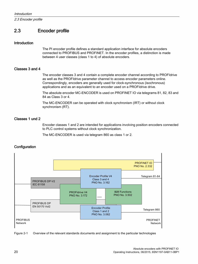
2.3 Encoder profile
IntroductionThe PI encoder profile defines a standard application interface for absolute encoders connected to PROFIBUS and PROFINET. In the encoder profiles, a distinction is made between 4 user classes (class 1 to 4) of absolute encoders.
Classes 3 and 4The encoder classes 3 and 4 contain a complete encoder channel according to PROFIdrive as well as the PROFIdrive parameter channel to access encoder parameters online. Correspondingly, encoders are generally used for clock-synchronous (isochronous) applications and as an equivalent to an encoder used on a PROFIdrive drive.
The absolute encoder MC-ENCODER is used on PROFINET IO via telegrams 81, 82, 83 and 84 as Class 3 or 4.
The MC-ENCODER can be operated with clock synchronism (IRT) or without clock synchronism (RT).
Classes 1 und 2Encoder classes 1 and 2 are intended for applications involving position encoders connected to PLC control systems without clock synchronization.
The MC-ENCODER is used via telegram 860 as class 1 or 2.
Configuration
Figure 2-1 Overview of the relevant standards documents and assignment to the particular technologies
Introduction2.3 Encoder profile
Absolute encoders with PROFINET IO 20 Operating Instructions, 06/2015, 6SN1197-0AB11-0BP1
2.4 Features of the MC-ENCODERThe MC-ENCODER is a Class 4 absolute encoder and therefore also supports all of the functions of a Class 3 absolute encoder.
In addition, the MC-ENCODER can also be used in applications via telegram 860, where functions according to Class 1 and Class 2 are required.
The basic functions include:
● Communication interface PROFINET IO V2.2
● Neighbor detection
● Engineering identification call
● Support of encoder profile V4.1 (Class 3, Class 4)
● Support of encoder profile telegrams 81, 82, 83 and 84
● Support of vendor-specific telegram 860 (for Class 1, Class 2 applications)
● Support of PROFIdrive BMP parameter channel
● Integrated velocity calculation with selectable velocity filters and scaling
● Integrated round axis (endless shaft) functionality
● Integrated bootloader for encoder firmware upgrade
Introduction2.4 Features of the MC-ENCODER
Absolute encoders with PROFINET IO Operating Instructions, 06/2015, 6SN1197-0AB11-0BP1 21

2.5 Encoder functionsThe following table provides you with an overview of the functions supported by MC-ENCODER in the particular application classes.
Table 2-1 Overview of the functions
Function Telegram 860Class 1, Class 2
Telegram 81 - 84Class 3, Class 4
Code sequence ✓ ✓Round axis (endless shaft) ✓ ✓Class 3 functionality - ✓Class 4 functionality - ✓Scaling function ✓ ✓G1_XIST1 preset control - ✓G1_XIST1 offset control - ✓Telegram 860 preset control ✓ -Preset value 64 bit - -Velocity signal 16 bit - ✓Velocity signal 32 bit ✓ ✓Velocity filter ✓ ✓Configurable velocity measuring unit ✓ ✓Sign-of-life supervision - ✓Configurable controller sign-of-life supervision - ✓Operation time - -PROFIdrive fault buffer - -Alarm channel diagnostics >V1.0 >V1.0
Introduction2.5 Encoder functions
Absolute encoders with PROFINET IO 22 Operating Instructions, 06/2015, 6SN1197-0AB11-0BP1

Installing 33.1 Electrical connection
The encoder is connected using one 4-pin M12 connector for the power supply and two 4-pin D-coded M12 connectors for Ethernet.
The encoder uses a second D-coded connector and provides an integrated switch function. The installation instructions are located on or in the packaging of the connector.
Adapters for the field wiring can be ordered.
See chapter: Accessories (Page 95)
or
See catalog: “SIMOTION & SINAMICS PM 21,” part 7: Measuring systems
Ethernet connector
Pin number Signal1 Tx +2 Rx +3 Tx -4 Rx -
Figure 3-1 4-pin, socket, D-coded
Absolute encoders with PROFINET IO Operating Instructions, 06/2015, 6SN1197-0AB11-0BP1 23

Connector for power supply
Pin number Signal1 US (10 – 30 V DC)2 Not connected3 GND (0 V)4 Not connected
Figure 3-2 4-pin, connector, A-coded
Installing 3.1 Electrical connection
Absolute encoders with PROFINET IO 24 Operating Instructions, 06/2015, 6SN1197-0AB11-0BP1

3.2 Ethernet cables
Table 3-1 RJ45 - M12 crossover
Signal RJ45 Pin M12 PinTx + 1 2Tx - 2 4Rx + 3 1Rx - 6 3
Table 3-2 M12 - M12 crossover
Signal M12 Pin M12 PinTx + 1 1Tx - 2 2Rx + 3 3Rx - 4 4
Table 3-3 RJ45 - M12 crossover
Signal RJ45 Pin M12 straightTx + 1 1Tx - 2 2Rx + 3 3Rx - 6 4
Installing 3.2 Ethernet cables
Absolute encoders with PROFINET IO Operating Instructions, 06/2015, 6SN1197-0AB11-0BP1 25

3.3 Diagnostic LEDs
Table 3-4 Diagnostic LED
LED Color Description for LED = onActive1 Yellow Incoming and outgoing data traffic via port 1Link1* Green Link to another Ethernet component via port 1Active2 Yellow Incoming and outgoing data traffic via port 2Link2* Green Link to another Ethernet component for port 2Stat1 Green Status 2, see chapter Status LED indication (Page 27) Stat2 Red Status 2, see chapter Status LED indication (Page 27) * Flashes with 2 Hz if engineering identification call is activated and link connection is available
Installing 3.3 Diagnostic LEDs
Absolute encoders with PROFINET IO 26 Operating Instructions, 06/2015, 6SN1197-0AB11-0BP1

3.4 Status LED indication
Figure 3-3 LED indication
Table 3-5 Status LED indication
Status 1Green
Status 2Red (bus failure)
Meaning Cause
Off Off No power On On No connection to a controller
Criteria: no data exchange● Bus disconnected● IO-controller not available● IO-controller switched off
On Blinking * ● Parameterization fault, no data exchange
● Criteria: data communication correct. However, the IO-device did not switch to the data exchange mode
● IO-device not configured yet or wrong configuration
● Wrong station address assigned (but not outside the permitted range)
● Actual configuration of the IO-device differs from the nominal configuration
On Off Mode: Data exchangeIO-device and operation ok
* The blinking frequency is 0.5 Hz. Minimum indication time is 3 sec.
Installing 3.4 Status LED indication
Absolute encoders with PROFINET IO Operating Instructions, 06/2015, 6SN1197-0AB11-0BP1 27

3.5 Instructions for mechanical installation and electrical connection of the encoder
The following points should be observed during the installation and electrical connection of the encoder.
● Do not drop the angular encoder or subject it to excessive vibration. The encoder is a precision device.
● Do not open the angular encoder housing. If the device is opened and closed again, it can be damaged and dirt may enter the unit.
● The shaft of a full shaft encoder must be connected with the shaft of the suitable measuring object via a shaft coupling. This coupling is used to dampen vibration and imbalance on the encoder shaft and to avoid inadmissibly high forces. Suitable couplings are available from Siemens. Additional data is provided in the Catalog: "SIMOTION & SINAMICS PM 21", Part 7: Measuring systems.
● Although Siemens absolute encoders are rugged, when used in harsh ambient conditions, they should be protected against damage using suitable protective measures. The encoder should not be used as handles or steps.
● Only qualified personnel shall commission and operate these devices. These are personnel who are authorized to commission, ground and tag devices, systems and circuits according to the current state of safety technology.
● It is not permissible to make any electrical changes to the encoder.
● Route the connecting cable to the angular encoder at a considerable distance or completely separated from power cables with their associated noise. Completely shielded cables must be used for reliable data transfer and good grounding must be provided. Cabling, establishing and interrupting electrical connections may only be carried-out when the equipment is in a no-voltage condition. Short-circuits, voltage spikes etc. can result in malfunctions and uncontrolled states which can even include severe personnel injury and material damage.
● The encoder must be connected to PE through a large surface area. If the flange does not have a good electrical connection to the machine – i.e. if a plastic mounting device was used – then use e.g. a 30cm long and 2cm wide copper strap to establish the PE connection
Before powering-up the system, check all of the electrical connections. Connections, which are not correct, can cause the system to malfunction. Faulty connections can result in severe personnel injury and material damage.
Installing 3.5 Instructions for mechanical installation and electrical connection of the encoder
Absolute encoders with PROFINET IO 28 Operating Instructions, 06/2015, 6SN1197-0AB11-0BP1

Cyclic Data Exchange 4Setpoints and actual values to the absolute encoder are cyclically exchanged using standard telegrams, refer to the Telegrams (Page 39). The standard telegrams comprise a fixed compilation of signals, refer to the Signal list for cyclic data transmission (Page 30).
The structure of the telegrams as well as the content of the signals contained in them are provided in this documentation:
LiteratureEncoder profil
Additional literature (Page 101) [1]
PROFIdrive standard
Additional literature (Page 101) [2]
Absolute encoders with PROFINET IO Operating Instructions, 06/2015, 6SN1197-0AB11-0BP1 29

4.1 Signal list for cyclic data transmission
Table 4-1 Signal list
Signal
Significance PROFIdrivesignal No.
Data type
STW2_ENC Encoder control word 80 U16ZSW2_ENC Encoder status word 81 U16NIST_A Velocity value A 6 I16NIST_B Velocity value B 8 I32G1_STW Sensor control word 9 U16G1_ZSW Sensor status word 10 U16G1_XIST1 Sensor position actual value 1 11 U32G1_XIST2 Sensor position actual value 2 12 U32G1_XIST3 Sensor position actual value 3 39 U64G1_XIST_PRESET_A Sensor position preset control word 32 bit 238 U32
Cyclic Data Exchange4.1 Signal list for cyclic data transmission
Absolute encoders with PROFINET IO 30 Operating Instructions, 06/2015, 6SN1197-0AB11-0BP1
4.2 Format of actual position values G1_XThe signals G1_XIST1 and G1_XIST2 represent the actual position values. For the MC-ENCODER the format for both signals is right aligned and fixed. See table G1_XIST1 (Page 31), G1_XIST2 (Page 32) below.
As the MC-ENCODER is a gray-coded absolute encoder, in G1_XIST it permanently supplies the absolute value – and G1_XIST2 supplies no additional value regarding the absolute value. If you directly access the position actual value in telegrams 81 - 84 from the user program, then you read out the position actual value from G1_XIST1 and you only use G2_XIST2 to read out the error code in the case of an error.
Note
The MC-ENCODER is using fixed shift factors for XIST1 and XIST2. There is no possibility to configure the shift factor. The shift factors are always zero and can be read out of parameter 979 by the controller or a supervisor:● P979, Subindex 3 (Shift factor for G1_XIST1) = 0● P979, Subindex 4 (Shift factor for G1_XIST2) = 0
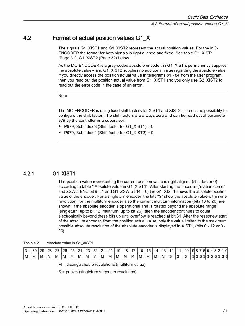
4.2.1 G1_XIST1The position value representing the current position value is right aligned (shift factor 0) according to table " Absolute value in G1_XIST1". After starting the encoder ("station come" and ZSW2_ENC bit 9 = 1 and G1_ZSW bit 14 = 0) the G1_XIST1 shows the absolute position value of the encoder. For a singleturn encoder, the bits "S" show the absolute value within one revolution, for the multiturn encoder also the current multiturn information (bits 13 to 26) are shown. If the absolute encoder is operational and is rotated beyond the absolute range (singleturn: up to bit 12, multiturn: up to bit 26), then the encoder continues to count electronically beyond these bits up until overflow is reached at bit 31. After the reset/new start of the absolute encoder, from the position actual value, only the value limited to the maximum possible absolute resolution of the absolute encoder is displayed in XIST1, (bits 0 - 12 or 0 - 26).
Table 4-2 Absolute value in G1_XIST1
31 30 29 28 27 26 25 24 23 22 21 20 19 18 17 16 15 14 13 12 11 10 9 8 7 6 5 4 3 2 1 0M M M M M M M M M M M M M M M M M M M S S S S S S S S S S S S S
M = distinguishable revolutions (multiturn value)
S = pulses (singleturn steps per revolution)
Cyclic Data Exchange4.2 Format of actual position values G1_X
Absolute encoders with PROFINET IO Operating Instructions, 06/2015, 6SN1197-0AB11-0BP1 31
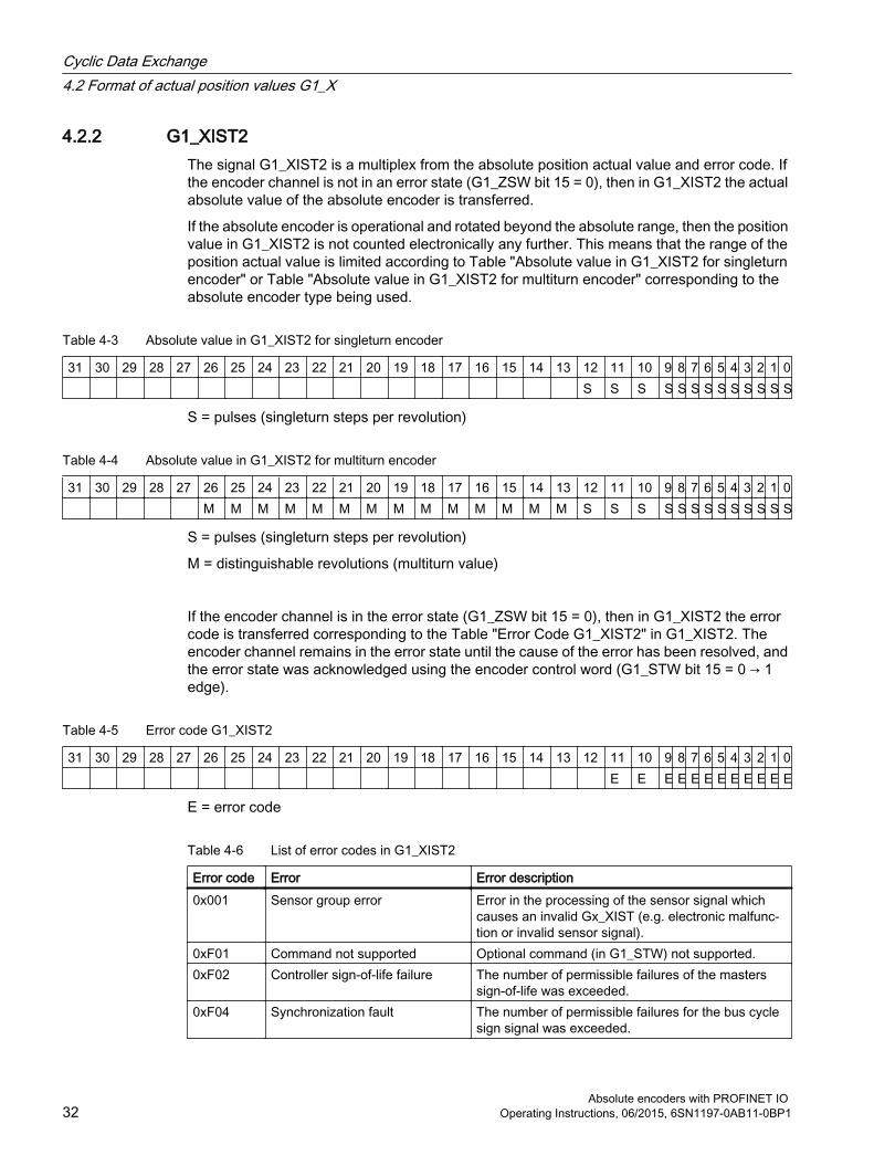
4.2.2 G1_XIST2The signal G1_XIST2 is a multiplex from the absolute position actual value and error code. If the encoder channel is not in an error state (G1_ZSW bit 15 = 0), then in G1_XIST2 the actual absolute value of the absolute encoder is transferred.
If the absolute encoder is operational and rotated beyond the absolute range, then the position value in G1_XIST2 is not counted electronically any further. This means that the range of the position actual value is limited according to Table "Absolute value in G1_XIST2 for singleturn encoder" or Table "Absolute value in G1_XIST2 for multiturn encoder" corresponding to the absolute encoder type being used.
Table 4-3 Absolute value in G1_XIST2 for singleturn encoder
31 30 29 28 27 26 25 24 23 22 21 20 19 18 17 16 15 14 13 12 11 10 9 8 7 6 5 4 3 2 1 0 S S S S S S S S S S S S S
S = pulses (singleturn steps per revolution)
Table 4-4 Absolute value in G1_XIST2 for multiturn encoder
31 30 29 28 27 26 25 24 23 22 21 20 19 18 17 16 15 14 13 12 11 10 9 8 7 6 5 4 3 2 1 0 M M M M M M M M M M M M M M S S S S S S S S S S S S S
S = pulses (singleturn steps per revolution)
M = distinguishable revolutions (multiturn value)
If the encoder channel is in the error state (G1_ZSW bit 15 = 0), then in G1_XIST2 the error code is transferred corresponding to the Table "Error Code G1_XIST2" in G1_XIST2. The encoder channel remains in the error state until the cause of the error has been resolved, and the error state was acknowledged using the encoder control word (G1_STW bit 15 = 0 → 1 edge).
Table 4-5 Error code G1_XIST2
31 30 29 28 27 26 25 24 23 22 21 20 19 18 17 16 15 14 13 12 11 10 9 8 7 6 5 4 3 2 1 0 E E E E E E E E E E E E
E = error code
Table 4-6 List of error codes in G1_XIST2
Error code Error Error description0x001 Sensor group error Error in the processing of the sensor signal which
causes an invalid Gx_XIST (e.g. electronic malfunc‐tion or invalid sensor signal).
0xF01 Command not supported Optional command (in G1_STW) not supported.0xF02 Controller sign-of-life failure The number of permissible failures of the masters
sign-of-life was exceeded.0xF04 Synchronization fault The number of permissible failures for the bus cycle
sign signal was exceeded.
Cyclic Data Exchange4.2 Format of actual position values G1_X
Absolute encoders with PROFINET IO 32 Operating Instructions, 06/2015, 6SN1197-0AB11-0BP1

4.2.3 G1_XIST3The function and bit assignment of signal G1_XIST3 is identical to signal G1_XIST1 (Page 31) only with a 64 bit signal word.
Bit 32 up to bit 63 contain the multiturn information "M".
Signal G1_XIST3 can be beneficial, for example, if you wish to count the position actual value in the encoder directly electronically with 64 bit in order to eliminate having to perform a modulus calculation in the user program when the 32 bit position actual value overflows in G1_XIST1.
4.2.4 G1_XIST_PRESET_AUsing the G1_XIST_PRESET_A signal, the controller can enter a preset value for the MC-ENCODER via the cyclic data telegram, and activate this using the trigger bit. As the trigger bit is transferred in the same signal, in this case, only a preset value of maximum 31 bits can be entered.
The structure of the G1_XIST_PRESET_A signal is shown in the subsequent table "Absolute value in G1_XIST_PRESET".
With the 1 → 0 edge of the trigger bit, the actual preset value (bits 0 - 30) is accepted as actual value in G1_XIST1. When this preset value is accepted, then this is also retentively saved automatically. The reason for this is that absolute value set using a preset is also kept after a reset/new start of the absolute encoder.
If a preset has not been set, then set trigger bit 31 to the standard value of 0.
Note
The speed of the encoder shaft at the time that the preset value is set should be as low as possible or zero. As a consequence, the influence of the communication dead times on the preset value that has been set are kept as low as possible.
Table 4-7 Absolute value in G1_XIST_PRESET_A
31 30 29 28 27 26 25 24 23 22 21 20 19 18 17 16 15 14 13 12 11 10 9 8 7 6 5 4 3 2 1 0T P P P P P P P P P P P P P P P P P P P P P P P P P P P P P P P
P = preset value (31 bit) for G1_XIST1 in the format/resolution of G1_XIST1
T = trigger bit to control the transfer of the preset value
Cyclic Data Exchange4.2 Format of actual position values G1_X
Absolute encoders with PROFINET IO Operating Instructions, 06/2015, 6SN1197-0AB11-0BP1 33

4.3 Format of actual velocity values NISTThe velocity value, which is transferred in NIST_A or in NIST_B is a speed actual value calculated by the absolute encoder from the equidistant position sensing. By calculating the speed actual value at the absolute encoder in real-time, the controller can also be provided a high accuracy velocity signal without isochronous communication (without PROFINET IRT). In addition, you can utilize parameterizable filtering for the velocity signal in NIST_x.
The normalization of the value in NIST_x can be parameterized.
The following parameterization options exist:
● Increments / s
● Increments / 100 ms
● Increments / 10 ms
● Revolutions/ minute
● N2 / N4 normalization: Velocity normalization (scaling) as used in PROFIdrive telegrams. The velocity actual value in NIST is a percentage of the reference value. The reference value can also be programmed. In addition, the controller can read out the parameterized or active reference value via parameter p2000. Adapt the reference value to the particular application in order to optimally utilize the value range.
– for N2, 4000 hex corresponds to a value of 100 % of the reference value
– for N4, 4000 0000 hex corresponds to a value of 100 % of the reference value
– the value range extends from -200 % up to +200 %.MSB = 1 is a negative signMSB = 0 is a positive sign
Note
If the expected velocity value does not appear in signal NIST_x, then check the selected normalization or scaling for NIST.
Standard setting:● NIST_A = N2● NIST_B = N4
Cyclic Data Exchange4.3 Format of actual velocity values NIST
Absolute encoders with PROFINET IO 34 Operating Instructions, 06/2015, 6SN1197-0AB11-0BP1

4.4 Encoder control word (STW2_ENC)Signal STW2_ENC is used in telegrams 81 - 84.
The signal transfers the sign-of-life from the controller to MC-ENCODER. Further, in STW2_ENC, the controller must set bit 10 (control by PLC) to 1, in order to signal to the devices that the cyclic data are valid.
The Table "Bit assignment of STW2_ENC" shows the bit assignment of the STW2_ENC signal.
Note
If, in STW2_ENC, the controller does not set bit 10 to 1, then MC_ENCODER does not respond to the commands in G1_STW.
For clock cycle synchronous (isochronous) applications, the sign-of-life (sign-of-life counter) is used to monitor the correct synchronization of the controller processes to the sampling process in the absolute encoder.
The sign-of-life counter is a 4-bit counter. The controller application starts the sign-of-life with any value between 1 and 15. The controller increases the counter in every cycle of the controller application.
Valid values for the controller sign-of-life are 1 to 15, "0" indicates an error and is left out in normal operation.
Table 4-8 Bit assignment of STW2_ENC
Bit Value Significance Comments10 1 Control by PLC Control via interface, data is valid.
0 No control by PLC Data is not valid, except sign-of-life bits.12 ... 15 Controller sign-of-life Sending continuous counting value from 1 to 15.
Cyclic Data Exchange4.4 Encoder control word (STW2_ENC)
Absolute encoders with PROFINET IO Operating Instructions, 06/2015, 6SN1197-0AB11-0BP1 35

4.5 Encoder status word (ZSW2_ENC)Signal ZSW2_ENC is used in telegrams 81 – 84 to transfer the sign-of-life from the MC-ENCODER to the controller. Further, in ZSW2_ENC, the controller must evaluate bit 9 (control requested) in order to evaluate whether the cyclic data sent from the MC-ENCODER are valid, and the MC-ENCODER is ready to accept control commands.
The table "Bit assignment of ZSW2_ENC" indicates the bit assignment of the ZSW2_ENC signal.
Note
If, in ZSW2_ENC, bit 9 is not 1 then the information in G1_ZSW and G1_XIST_x is invalid and the MC-ENCODER does not respond to commands in the G1_STW.
For clock cycle synchronous applications, the sign-of-life (sign-of-life counter) is used to check the correct synchronization of the controller processes to the sampling process in the MC-ENCODER.
The sign-of-life counter is a 4-bit counter. The IO-device application starts the sign-of-life with any value between 1 and 15 after successful synchronization to the controller. The counter is increased by the IO-device in every data cycle.
Valid values for the IO-device sign-of-life are 1 to 15, "0" indicates an error and is left out in normal operation.
Note
If the MC-ENCODER identifies an error in the controller sign-of-life, then it stops sending the sign-of-life to the controller. This means that a missing sign-of-life (=0) from the MC-ENCODER to the controller can also be the consequence of an error in the controller sign-of-life to MC-ENCODER.
Table 4-9 Bit assignment of ZSW2_ENC
Bit Value Significance Comments9 1 Control requested The automation system is requested to assume control,
data is valid. 0 No control by PLC Data is not valid, except sign-of-life.12 .. 15 Encoder sign-of-life Sending continuous counting value from 1 to 15.
Cyclic Data Exchange4.5 Encoder status word (ZSW2_ENC)
Absolute encoders with PROFINET IO 36 Operating Instructions, 06/2015, 6SN1197-0AB11-0BP1

4.6 Sensor control word (G1_STW)Signal G1_STW is used to control the state machine of the PROFIdrive encoder channel. As the MC-ENCODER is a gray-coded absolute encoder, the following functions are often significant:
● Preset of the absolute position
● Encoder parking
● Error acknowledgment
Table 4-10 Bit assignment of G1_STW
Bit Value Function Comments0 ... 10 Reserved, currently not used.11 0/1 Home position mode Specifies if the position value shall be set to a previously
configured absolute value or shifted by this value.0: set home position / preset (absolute)1: shift home position / preset (relative = offset)
12 1 Set preset / request shift Preset (resp. shift) is set when changing this Bit to "1" (rising edge). Default preset value (shift): 0Note: It can also be parameterized that with a rising edge, the value XIST1 also makes a step.
13 1 Request absolute value cyclically
Request of additional cyclic transmission of the absolute actual position in G1_XIST2. If no other data needs to be transferred due to commands or errors the absolute position value will be transmitted automatically.
14 1 Activate parking sensor If the "activate parking sensor" bit is set, the encoder is switched inactive and error will be reset. While the en‐coder is in the parking state, no errors will be generated.
15 1 Acknowledging a sen‐sor error
Request to acknowledge / reset a sensor error.
By appropriately parameterizing the absolute encoder, when accepting the preset value, you can set whether this is also directly accepted in G1_XIST1 or G1_XIST3. When the preset value is accepted, this value is also retentively saved automatically. This is to ensure that an absolute value set using preset is also kept after a reset/power up of the absolute encoder.
Cyclic Data Exchange4.6 Sensor control word (G1_STW)
Absolute encoders with PROFINET IO Operating Instructions, 06/2015, 6SN1197-0AB11-0BP1 37

4.7 Sensor status word (G1_ZSW)Signal G1_ZSW is used to control the state machine of the PROFIdrive encoder channel and is the counterpart to control word G1_STW.
Table 4-11 Bit assignment of G1_ZSW
Bit Value Meaning Comment0 … 10 Reserved, currently not used.11 Acknowledgement sensor
error in processIs set while requested error acknowledge is pro‐cessed. Handshake signal related to G1_STW bit 15.
12 1 Set preset / shift reference point executed
Acknowledgement for "set preset / request shift".
13 1 Transmit absolute value cy‐clically
Acknowledgement for "request absolute value cy‐clically".
14 1 Parking sensor activated Acknowledgement for "activate parking sensor". The encoder transmits no valid position value, sen‐sor errors are reset.
15 1 Sensor error Indicates a sensor error. A device specific error code is transmitted in G1_XIST2.
Cyclic Data Exchange4.7 Sensor status word (G1_ZSW)
Absolute encoders with PROFINET IO 38 Operating Instructions, 06/2015, 6SN1197-0AB11-0BP1
4.8 TelegramsThe interface for cyclic data of the MC-ENCODER is configured by selecting one of the following standard telegrams. The necessary standard telegram is selected by inserting the relevant telegram submodule when the PROFINET configuration of the encoder is set up in STEP 7 “HW Config,” see also: Configuration (Page 43)
Standard telegrams 81 to 84 are typically used if the encoder is used together with a Motion Control system with PROFIdrive interface, such as SIMOTION or SINUMERIK. Telegrams 81 to 84 provide a standard PROFIdrive sensor interface, which is the same as the sensor interface of a standard drive. Nevertheless, telegrams 81 to 84 can also be used with a programmable controller if it is necessary to monitor signs of life or error codes via a cyclic interface.
For simpler applications, convenient transmission of position and speed actual values to programmable controllers is possible via telegram 860.
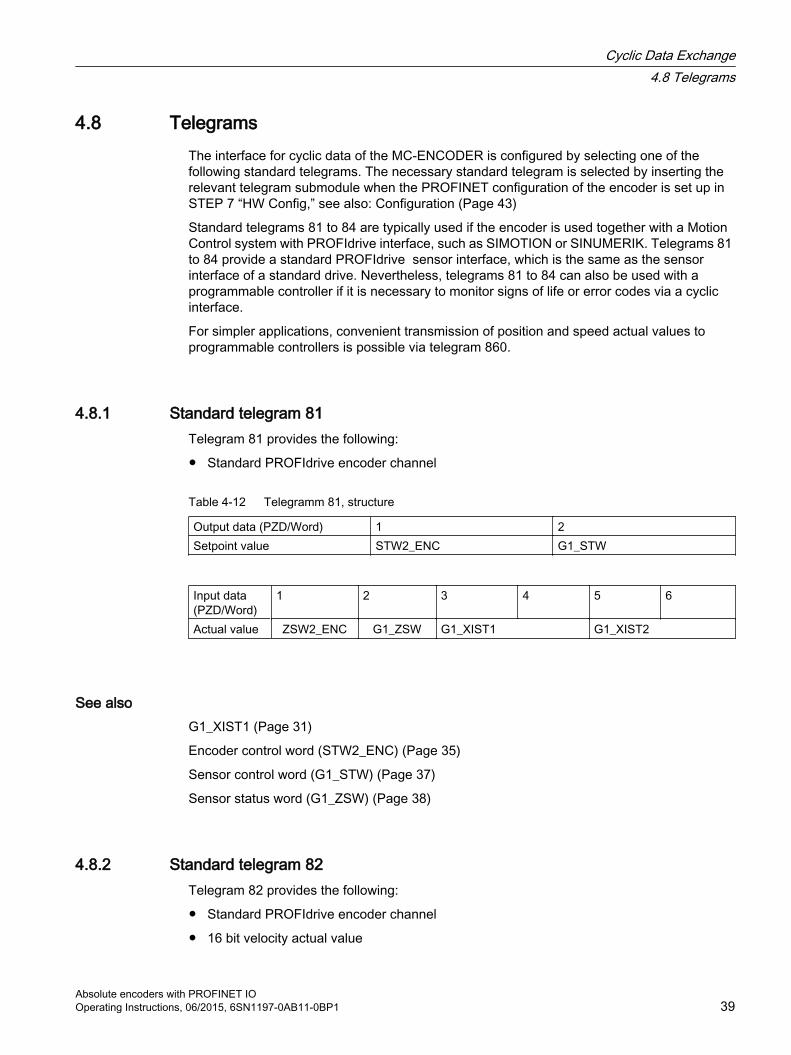
4.8.1 Standard telegram 81Telegram 81 provides the following:
● Standard PROFIdrive encoder channel
Table 4-12 Telegramm 81, structure
Output data (PZD/Word) 1 2Setpoint value STW2_ENC G1_STW
Input data (PZD/Word)
1 2 3 4 5 6
Actual value ZSW2_ENC G1_ZSW G1_XIST1 G1_XIST2
See alsoG1_XIST1 (Page 31)
Encoder control word (STW2_ENC) (Page 35)
Sensor control word (G1_STW) (Page 37)
Sensor status word (G1_ZSW) (Page 38)
4.8.2 Standard telegram 82Telegram 82 provides the following:
● Standard PROFIdrive encoder channel
● 16 bit velocity actual value
Cyclic Data Exchange4.8 Telegrams
Absolute encoders with PROFINET IO Operating Instructions, 06/2015, 6SN1197-0AB11-0BP1 39

Table 4-13 Telegram 82, structure
Output data (PZD/Word) 1 2Setpoint value STW2_ENC G1_STW
Input data (PZD/Word)
1 2 3 4 5 6 7
Actual value ZSW2_ENC G1_ZSW G1_XIST1 G1_XIST2 NIST_A
4.8.3 Standard telegram 83Telegram 83 provides the following:
● Standard PROFIdrive encoder channel
● 32 bit velocity actual value
Table 4-14 Telegram 83, structure
Output data (PZD/Word) 1 2Setpoint value STW2_ENC G1_STW
Input data (PZD/Word)
1 2 3 4 5 6 7 8
Actual value ZSW2_ENC G1_ZSW G1_XIST1 G1_XIST2 NIST_B
4.8.4 Standard telegram 84Telegram 84 provides the following:
● PROFIdrive encoder channel with a 64 bit XIST
● 32 bit velocity actual value
Table 4-15 Telegram 84, structure
Output data (PZD/Word) 1 2Setpoint value STW2_ENC G1_STW
Input data (PZD/Word)
1 2 3 4 5 6 7 8 9 10
Actual value ZSW2_ENC G1_ZSW G1_XIST3 G1_XIST2 NIST_B
Cyclic Data Exchange4.8 Telegrams
Absolute encoders with PROFINET IO 40 Operating Instructions, 06/2015, 6SN1197-0AB11-0BP1

4.8.5 Telegram 860Telegram 860 provides the following:
● 32 bit position actual value XIST1
● 32 bit velocity actual value
● Using cyclic data, in the G1_XIST_PRESET_A signal a preset value can be entered for the position and activated.
Note
The telegram does not have a sign-of-life monitoring.
Encoded diagnostics is only possible using the standard PROFINET diagnostics.
Table 4-16 Telegram 860, structure
Output data (PZD/Word) 1 2Setpoint value G1_XIST_PRESET_A
Input data (PZD/Word)
1 2 3 4
Actual value G1_XIST1 NIST_B
Cyclic Data Exchange4.8 Telegrams
Absolute encoders with PROFINET IO Operating Instructions, 06/2015, 6SN1197-0AB11-0BP1 41

Cyclic Data Exchange4.8 Telegrams
Absolute encoders with PROFINET IO 42 Operating Instructions, 06/2015, 6SN1197-0AB11-0BP1

Configuration 5The MC-ENCODER with PROFINET IO interface has to be configured by parameterization corresponding to the purpose of the application. The GSDML file pertaining to the encoder has to be installed in the PLC engineering software tool that is being used to enable this configuration.
Absolute encoders with PROFINET IO Operating Instructions, 06/2015, 6SN1197-0AB11-0BP1 43

5.1 Encoder configuration overview
1
12
① Offline configuration path via the hardware configuration② Online access to encoder parameters via the non-cyclic parameter channel
Figure 5-1 Rotary encoder functions
The MC-ENCODER is essentially configured and parameterized offline using STEP7 HW-Config (Figure: ①).
In online operation of the MC-ENCODER, a non-cyclic parameter channel according to the encoder profile/x/ or PROFIdrive profile/y/is also available (Figure: ②). Using this PROFIdrive parameter channel, parameters can be read and write accessed in online operation.
LiteratureYou can find additional information on this topic in this documentation:
Additional literature (Page 101) [3b]
Encoder-Profil
Additional literature (Page 101) [1]
PROFIdrive-Norm
Additional literature (Page 101) [2]
Configuration5.1 Encoder configuration overview
Absolute encoders with PROFINET IO 44 Operating Instructions, 06/2015, 6SN1197-0AB11-0BP1

5.2 Encoder offline configurationThe MC-ENCODER is configured and parameterized offline using STEP7 HW Config. HW Config is made aware of the MC-ENCODER by importing the GSDML of the encoder device.
ProcedureAfter importing the GSDML, the MC-ENCODER is inserted into the project and configured and/or parameterized.
After compiling the project, when the project is downloaded to the controller (SIMATIC or SIMOTION CPU), then the encoder parameterization is also transferred. When the CPU goes online and when the PROFINET connection is established to the MC-ENCODER, then also the parameterization is automatically transferred to the encoder (PRM data record) and becomes active.
When configuring the MC-ENCODERS in the HW Config, then principally, a distinction is made between the following three configuration areas:
Interface configuration, PROFINETConfiguration of the general communication properties of the encoder PROFINET interface e.g.:
● RT/IRT communication
● Cycle time
● Times Ti and To (for IRT operation)
You configure the properties at the interface submodule X1 at slot 0.
Configuration, telegramsBy selecting the telegram, you select the type of cyclic interface of the MC-ENCODER. The configuration is realized by selecting and inserting the appropriate telegram submodule (81, 82, 83, 84, 860).
Function configuration, MC-ENCODERUsing the encoder parameters in the MAP submodule, then for example, the following individual MC-ENCODER functions are configured:
● Parameterization of the direction of rotation
● Optional scaling function
Configuration5.2 Encoder offline configuration
Absolute encoders with PROFINET IO Operating Instructions, 06/2015, 6SN1197-0AB11-0BP1 45

● Velocity signal
● Sign-of-life monitoring
Figure 5-2 Encoder access points for configuration and parameterization
Configuration5.2 Encoder offline configuration
Absolute encoders with PROFINET IO 46 Operating Instructions, 06/2015, 6SN1197-0AB11-0BP1
5.3 Encoder parameter description
5.3.1 Encoder parameter
Parameter setting optionsThe MC-ENCODER parameters can be set offline using HW Config.
For specific parameters there is also the option of being able to access these online via the non-cyclic parameter channel – as well as retentively saving these in the encoder.
Also refer to:
Encoder configuration overview (Page 44)
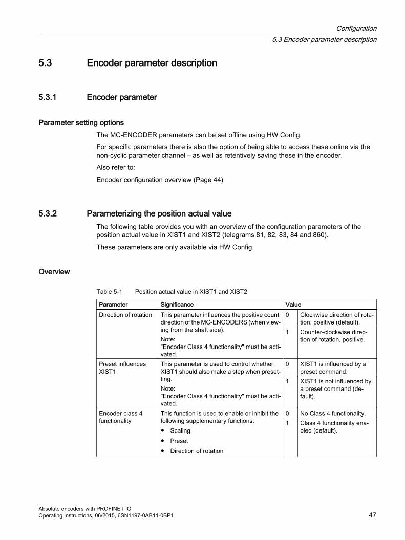
5.3.2 Parameterizing the position actual valueThe following table provides you with an overview of the configuration parameters of the position actual value in XIST1 and XIST2 (telegrams 81, 82, 83, 84 and 860).
These parameters are only available via HW Config.
Overview
Table 5-1 Position actual value in XIST1 and XIST2
Parameter Significance ValueDirection of rotation This parameter influences the positive count
direction of the MC-ENCODERS (when view‐ing from the shaft side). Note:"Encoder Class 4 functionality" must be acti‐vated.
0 Clockwise direction of rota‐tion, positive (default).
1 Counter-clockwise direc‐tion of rotation, positive.
Preset influences XIST1
This parameter is used to control whether, XIST1 should also make a step when preset‐ting.Note:"Encoder Class 4 functionality" must be acti‐vated.
0 XIST1 is influenced by a preset command.
1 XIST1 is not influenced by a preset command (de‐fault).
Encoder class 4 functionality
This function is used to enable or inhibit the following supplementary functions:● Scaling● Preset● Direction of rotation
0 No Class 4 functionality.1 Class 4 functionality ena‐
bled (default).
Configuration5.3 Encoder parameter description
Absolute encoders with PROFINET IO Operating Instructions, 06/2015, 6SN1197-0AB11-0BP1 47

Enabled/disabled functionsThe following table provides you with an overview of the enabled/disabled MC-ENCODER functions depending on the setting of "Encoder Class 4 functionality".
Table 5-2 Overview of the functions
Function Class 4 functionality disabled
Class 4 functionality ena‐bled
Code sequence - ✓G1_XIST1 preset control - ✓Scaling function control - ✓Alarm channel control ✓ ✓Preset value - ✓Preset value 64 bit - -Measuring units per revolution / measuring step - ✓Total measuring range - ✓Measuring units per revolution 64 bit - ✓Total measuring range 64 bit - ✓Maximum controller sign-of-life failures - ✓Velocity measuring unit ✓ ✓Operating time - -Offset line - ✓Offset value - ✓Offset value 64 bit - ✓Rotary axis (endless shaft) Always active Always activeVelocity filter ✓ ✓
5.3.3 Parameterizing the scaling functionThe following table provides you with an overview of the configuration parameters of the scaling function for the position actual value XIST1 and XIST2 (telegrams 81, 82, 83, 84 and 860).
These parameters are only available via HW Config.
Overview
Table 5-3 Scaling function in XIST1 and XIST2
Parameter Significance ValueScaling function Using this parameter, the scaling function in the
MC-ENCODER is enabled or disabled. Note:"Encoder Class 4 functionality" must be activated, otherwise the scaling function is always off.
0 Scaling off (default)1 Scaling enabled
Configuration5.3 Encoder parameter description
Absolute encoders with PROFINET IO 48 Operating Instructions, 06/2015, 6SN1197-0AB11-0BP1
Parameter Significance ValueScaling: resolution per revolution
Singleturn resolution in increments per revolution when the scaling function is active.
11 Unsigned 32
Scaling:Total resolution
Absolute measuring range in increments per rev‐olution when the scaling function is active.
11 Unsigned 32
5.3.4 Parameterizing the velocity signalAn overview of the configuration parameters of the velocity signal in NIST_A or NIST_B (telegrams 82, 83, 84 and 860) is provided in the following table.
Parameters "Speed filtering" and "Speed scaling" are only available via HW Config.
Parameter "Reference speed N2/N4" can be set via HW Config, and can be read via the parameter channel of parameter p2000.
Overview
Table 5-4 Velocity signal in NIST_A and NIST_B
Parameter Significance ValueSpeed filtering Active velocity filter for the speed actual
value in NIST_x.1 Fine (no filtering)2 Medium (default)3 Coarse
Speed scaling Unit or scaling of the velocity actual value in NIST_x.
0 Increments / s1 Increments / 100 ms2 Increments / 10 ms3 rpm4 N2/N4 scaling
Reference speed N2/N4 (rpm)
Speed reference value for 100 % for selec‐ted N2/N4 scaling in rpm.
UINT 32
5.3.5 Parameterizing the communication interfaceThe following table provides you with an overview of the configuration parameters to configure help functions in the cyclic communication channel (telegrams 81, 82, 83, 84 and 860).
Parameters "Compatibility module V3.1" and "Diagnostics via alarm channel" are only available via HW Config.
Parameter "Tolerable sign-of-life error" can be set via HW Config and can also be additionally read and written to via the parameter channel as parameter 925.
Configuration5.3 Encoder parameter description
Absolute encoders with PROFINET IO Operating Instructions, 06/2015, 6SN1197-0AB11-0BP1 49

Overview
Table 5-5 Help functions in the cyclic communication channel
Parameter Significance ValueTolerated sign-of-life error
This parameter is used to set the maxi‐mum number of tolerated sign-of-life er‐rors. Note:The "Compatibility mode V3.1" must be activated.The setting has no effect for telegram 860.
0 No error tolerated (e.g. for communica‐tion test)
1... 254 Number of tolerated sign-of-life errors (1 = default)
255 Monitoring off (e.g. for commissioning)
Compatibility mode V3.1
Using this parameter, an encoder inter‐face behavior compatible with encoder profile V3.1 is set (only for compatibility in previous projects).Note:The setting has no effect for telegram 860.
0 V3.1 compatibility1 V4.x interface (default)
Diagnostics via alarm channel
Using this parameter, diagnostic alarms are either enabled or disabled via the PROFINET alarm channel. Note:"Compatibility mode V3.1" must be acti‐vated, as otherwise, the diagnostic alarms are always enabled.
0 Alarm channel disa‐bled (default)
1 Alarm channel ena‐bled
OverviewIn the online operation of the MC-ENCODER, a non-cyclic parameter channel according to the encoder profile/x/or PROFIdrive profile/y/is available. Parameters can be read and write accessed in online operation using this PROFIdrive parameter channel.
For MC-ENCODER, the access point to this parameter channel is at the MAP submodule (module 1, submodule 1.1) via the data record with index 0xB02E.
Access to the parameter channel is realized via the non-cyclic communication channel and is therefore possible by the controller as well as also a supervisor.
LiteratureYou can find a detailed description of the access protocol in the following documentation: Additional literature:
Additional literature (Page 101) [3b]
Configuration5.3 Encoder parameter description
Absolute encoders with PROFINET IO 50 Operating Instructions, 06/2015, 6SN1197-0AB11-0BP1

Parameters supported via parameter channelBelow is a list of the online parameters available via the parameter channel on the MC-ENCODER with their properties.
Table 5-6 MC-ENCODER PROFIdrive parameters
Number Parameter Significance Data type Access922 Telegram selection Information about the currently set tele‐
gram (PROFIdrive parameters).Unsigned16 Read only
925 Number of controller sign-of-life failures which may be tol‐erated
Maximum number of tolerated sign-of-life errors (PROFIdrive parameters).
Unsigned16 Read/write
964 Drive unit identification Information about the manufacturer, type, version of the encoder (PROFIdrive param‐eters).
Array[6] Un‐signed16
Read only
965 Profile identification number Information about the supported encoder profile version (PROFIdrive parameters).
Octet string[2] Read only
971 Transfer into non volatile memory
The parameter set is saved in the NV-RAM (PROFIdrive parameters).
Unsigned16 Read/write
975 EO identification Profile-specific information on the encoder object/module 1 (PROFIdrive parameters).
Array[n] Un‐signed32
Read only
979 Sensor format Information on the position sensor (PROFI‐drive parameters).
Array[n] Un‐signed32
Read only
980 Number list of defined pa‐rameter
List of all of the parameters available online via the parameter channel (PROFIdrive pa‐rameters). [2]
Array[n] Un‐signed16
Read only
2000 Velocity reference value Speed reference value for 100% in the speed actual value signal NIST_A or NIST_B.
Float32 Read only
65000 Preset value Position preset value, which for telegrams 81, 82, 83 and 84, which become active when using the set/shift home position func‐tion via G1_STW, bit 12 (encoder profile parameter).
Integer32 Read/write
65001 Operating status Information about the actual configuration and error status of the encoder (encoder profile parameter).[1]
Array[n] Integer 32
Read only
LiteratureAdditional literature (Page 101) [1]
Additional literature (Page 101) [2]
Configuration5.3 Encoder parameter description
Absolute encoders with PROFINET IO Operating Instructions, 06/2015, 6SN1197-0AB11-0BP1 51

Configuration5.3 Encoder parameter description
Absolute encoders with PROFINET IO 52 Operating Instructions, 06/2015, 6SN1197-0AB11-0BP1

Operating with STEP7 6In the following chapter the configuration of the encoder with the configuration tool STEP7 "HW Config" is shown as example.
Absolute encoders with PROFINET IO Operating Instructions, 06/2015, 6SN1197-0AB11-0BP1 53

6.1 Installing the GSDML fileIf the MC-ENCODER is used for the first time it is necessary to install the GSDML file to import the encoder description into the hardware catalog of the HW Config-tool:
Choose "Install GSD File..." in the HW Config-window of the project (menu item "Options") and select the GSDML-file.
The GSDML file is supplied by SIEMENS. In order to represent the encoder with a bitmap in STEP7; the bitmap file will be installed automatically with the GSDML file – therefore both files must be in the same directory.
Figure 6-1 Installing GSD file in STEP7 HW Config
After the GSDML file has been successfully installed, the encoder can be found in the hardware catalog under "PROFINET-IO" – "Encoders".
Operating with STEP76.1 Installing the GSDML file
Absolute encoders with PROFINET IO 54 Operating Instructions, 06/2015, 6SN1197-0AB11-0BP1

6.2 Engineering the MC-ENCODER in a STEP7 projectTo engineer the encoder in a project, drag the desired device (e. g. Multiturn 27 Bit V 1.x) on to an existing PROFINET Ethernet network.
or
Choose the network and double-click the desired device (e. g. Multiturn 27 Bit V 1.x) icon.
Figure 6-2 Engineering an encoder in a STEP7 project
Double-click the encoder device icon (Slot "0", Module "MCxENCODER") to set the device properties.
Set a device name and by clicking on "Ethernet" set the IP address of the encoder.
Also, under the "IO cycle" tab, set the desired update time.
Operating with STEP76.2 Engineering the MC-ENCODER in a STEP7 project
Absolute encoders with PROFINET IO Operating Instructions, 06/2015, 6SN1197-0AB11-0BP1 55
Figure 6-3 Setting device properties
The device name and IP address now have to be set physically in the encoder.
Connect the PLC and encoder to the Ethernet and switch them on.
Click "PLC" → "Ethernet" → "Edit Ethernet Node" and click "Browse" for accessible Ethernet nodes in the new window.
STEP7 will scan for devices on the Ethernet and will displays them in a window.
Operating with STEP76.2 Engineering the MC-ENCODER in a STEP7 project
Absolute encoders with PROFINET IO 56 Operating Instructions, 06/2015, 6SN1197-0AB11-0BP1

Figure 6-4 Network browser
The encoder should be displayed under the device type MC-ENCODER.
Select this entry and click "Flash" to have the identification LED flash with 2 Hz.
Click "OK" to take the MAC address of the chosen device to the previous window and select "Use IP parameters".
The MAC address of the MC-ENCODER is available on the type plate (see the diagram below).
Enter the IP address (and subnet mask) for the encoder that you previously assigned and click "Assign IP configuration".
Also, enter the device name previously chosen in the text field "Device name" and click "Assign Name".
Operating with STEP76.2 Engineering the MC-ENCODER in a STEP7 project
Absolute encoders with PROFINET IO Operating Instructions, 06/2015, 6SN1197-0AB11-0BP1 57
Figure 6-5 Editing an Ethernet node
Note
If more than one encoder is used in the same PROFINET domain, each encoder must have a different name.
Operating with STEP76.2 Engineering the MC-ENCODER in a STEP7 project
Absolute encoders with PROFINET IO 58 Operating Instructions, 06/2015, 6SN1197-0AB11-0BP1

6.3 LLDP (Link Layer Discovery Protocol)The Link Layer Discovery Protocol allows a device in the PROFINET network to be replaced. The partner port in front of and behind the replaced device saves relevant information so that no additional configuration is necessary.
But the flag for activate "Device replacement without replacement medium" must be activated under the General tab.
Figure 6-6 Properties PNxIO
Using the Topology Editor in the STEP7 Hardware manager, it is possible to get an overview about the connections, the cable length and signal delay.
Operating with STEP76.3 LLDP (Link Layer Discovery Protocol)
Absolute encoders with PROFINET IO Operating Instructions, 06/2015, 6SN1197-0AB11-0BP1 59

Figure 6-7 Topology Editor, table view
Operating with STEP76.3 LLDP (Link Layer Discovery Protocol)
Absolute encoders with PROFINET IO 60 Operating Instructions, 06/2015, 6SN1197-0AB11-0BP1

Figure 6-8 Topology Editor, graphic view
It is possible to compare the configuration with the physical network.
Figure 6-9 Topology Editor, offline/online comparison
Operating with STEP76.3 LLDP (Link Layer Discovery Protocol)
Absolute encoders with PROFINET IO Operating Instructions, 06/2015, 6SN1197-0AB11-0BP1 61

6.4 Selecting the MC-ENCODER telegramThe functionality and interface is dependant on the selected telegram. The telegram is selected by inserting the appropriate telegram submodule (81, 82, 83, 84, 860).
Insert the corresponding telegram submodule by dragging it from the hardware catalog and dropping it into subslot 1.2 of the MC-ENCODER.
Figure 6-10 Selecting of telegram
Operating with STEP76.4 Selecting the MC-ENCODER telegram
Absolute encoders with PROFINET IO 62 Operating Instructions, 06/2015, 6SN1197-0AB11-0BP1

6.5 Setting encoder parametersSelect the encoder in the hardware configuration and double click the MAP submodule 1.1. The properties dialog will appear. The input addresses can be changed under the tab "Addresses" (if desired). To set the encoder parameters, the "Parameters" tab has to be selected.
Figure 6-11 Setting encoder parameters
Operating with STEP76.5 Setting encoder parameters
Absolute encoders with PROFINET IO Operating Instructions, 06/2015, 6SN1197-0AB11-0BP1 63

6.6 Setting device propertiesPROFINET IO Domain Management (i.e. right click on slot 0) allows the synchronization role and the RT class to be selected.
If the synchronization role is selected as "unsynchronized", then the encoder operates in the RT class. If sync controller is selected, then it is possible to switch between "high flexibility" (FLEX) and "high performance" (TOP).
Domain Management provides an overview of all of the available devices. All devices should use the same Synchronization Role and RT class.
Figure 6-12 Domain management
Operating with STEP76.6 Setting device properties
Absolute encoders with PROFINET IO 64 Operating Instructions, 06/2015, 6SN1197-0AB11-0BP1

Figure 6-13 Synchronization
Operating with STEP76.6 Setting device properties
Absolute encoders with PROFINET IO Operating Instructions, 06/2015, 6SN1197-0AB11-0BP1 65

6.7 IRT settingsThe upper limit for IRT transmission can be set.
Figure 6-14 IRT transmission
Operating with STEP76.7 IRT settings
Absolute encoders with PROFINET IO 66 Operating Instructions, 06/2015, 6SN1197-0AB11-0BP1

6.8 Changing and reading encoder parameters during the run-timeEncoder parameters will be set when configuring the encoder. You can find information on the parameters under: Encoder parameter description (Page 47)
To change or read encoder parameters in a STEP7 automation program, refer to system function blocks SFB53 and SFB52 (write/read record) or with the variable table for testing.
LiteratureFor additional information see
Additional literature (Page 101) [3b]
Operating with STEP76.8 Changing and reading encoder parameters during the run-time
Absolute encoders with PROFINET IO Operating Instructions, 06/2015, 6SN1197-0AB11-0BP1 67

6.9 Accessing cyclic data
SettingsTo access the cyclic data in the telegram, create a variable for each signal used in the telegram input and output data.
As a logical address, use the basis address of submodule 1.2 from HW Config and the relevant byte offset of the signal in the telegram.
Operating with STEP76.9 Accessing cyclic data
Absolute encoders with PROFINET IO 68 Operating Instructions, 06/2015, 6SN1197-0AB11-0BP1

Operating with SIMOTION 7In the following chapter the configuration and operation of the encoder with the SIMOTION controllers is shown. In this example SIMOTION SCOUT Version 4.2 is used.
Absolute encoders with PROFINET IO Operating Instructions, 06/2015, 6SN1197-0AB11-0BP1 69

7.1 Applications
ApplicationsIn general, there are two use case for operation of the encoder with SIMOTION:
● MC-ENCODER together with TO "External encoder":The MC-ENCODER is used as sensor device for the TO "External encoder". In this case, the encoder is typically operated isosynchronously (IRT device). The encoder is completely controlled by the TO. Sign-of-life monitoring is automatically used. Telegrams 81 or 83 are used.
● MC-ENCODER operated directly from AWP:The encoder telegram is directly accessed from the user program. The MC-ENCODER is completely controlled and managed by the user program. Telegram 860 is typically used.
In addition, SIMOTION provides system functions for accessing parameters online via the non-cyclic standard parameter channel for the MC-ENCODER. You can use these system functions for both of the applications described above.
Operating with SIMOTION7.1 Applications
Absolute encoders with PROFINET IO 70 Operating Instructions, 06/2015, 6SN1197-0AB11-0BP1

7.2 MC-ENCODER used together with TO External encoderThe following steps are necessary in order to configure the MC-ENCODER at SIMOTION as sensor at the TO " External encoder.
For the general procedure to create and configure MC-ENCODER in the HW Config, refer to the chapter Configuration (Page 43) and chapter Operating with STEP7 (Page 53)
You can find the online parameter access via the parameter channel in the chapter Online parameter access (Page 83)
Configuring MC-ENCODER in HW ConfigFor this particular application, select the following settings:
● IRT communication (IRT with high performance)
● Cycle time and Ti identical to the drive axes
● Select the telegram
– Telegram 81 or
– Telegram 83 (for 32 bit speed actual value NIST_B)
● Set the encoder parameters: Accept the default setting. If you use the speed actual value NIST from MC-ENCODER in the TO, then set the speed reference value in parameter "Reference speed N2/N4 (rpm)" to a value that is suitable for your application.
Operating with SIMOTION7.2 MC-ENCODER used together with TO External encoder
Absolute encoders with PROFINET IO Operating Instructions, 06/2015, 6SN1197-0AB11-0BP1 71

ExampleThe following example shows the configuration settings for the MC-ENCODER in HW Config for telegram 83 and a reference speed (100%) of 3000 rpm.
Figure 7-1 Example: Setting required in HW Config
Creating and configuring TO "External encoder"Insert a TO "External encoder" in the project and run the wizards for the external encoder configuration.
Operating with SIMOTION7.2 MC-ENCODER used together with TO External encoder
Absolute encoders with PROFINET IO 72 Operating Instructions, 06/2015, 6SN1197-0AB11-0BP1
Select the following settings:
● Encoder type: rotary
● Encoder type: absolute encoder or absolute encoder, cyclic, absolute
● Encoder mode: SSI
● Encoder pulse number: 8.192
● Fine resolution: 0
● Fine resolution, absolute value in Gn_XIST2: 0
● Data width, absolute value without fine resolution:
– 27 (for multiturn encoder) or
– 13 (for singleturn encoder)
● Encoder monitoring: activate
Procedure
Figure 7-2 Inserting an encoder
Operating with SIMOTION7.2 MC-ENCODER used together with TO External encoder
Absolute encoders with PROFINET IO Operating Instructions, 06/2015, 6SN1197-0AB11-0BP1 73

Figure 7-3 Configuring the encoder type
Operating with SIMOTION7.2 MC-ENCODER used together with TO External encoder
Absolute encoders with PROFINET IO 74 Operating Instructions, 06/2015, 6SN1197-0AB11-0BP1

Figure 7-4 Assigning an encoder, configuring the type and mode
Figure 7-5 Configuring an encoder
Operating with SIMOTION7.2 MC-ENCODER used together with TO External encoder
Absolute encoders with PROFINET IO Operating Instructions, 06/2015, 6SN1197-0AB11-0BP1 75

Figure 7-6 TO configuration, summary
Operating with SIMOTION7.2 MC-ENCODER used together with TO External encoder
Absolute encoders with PROFINET IO 76 Operating Instructions, 06/2015, 6SN1197-0AB11-0BP1
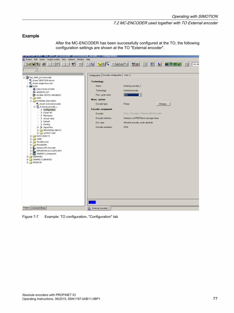
ExampleAfter the MC-ENCODER has been successfully configured at the TO, the following configuration settings are shown at the TO "External encoder".
Figure 7-7 Example: TO configuration, "Configuration" tab
Operating with SIMOTION7.2 MC-ENCODER used together with TO External encoder
Absolute encoders with PROFINET IO Operating Instructions, 06/2015, 6SN1197-0AB11-0BP1 77

Figure 7-8 Example: TO configuration, "Encoder configuration" tab
Operating with SIMOTION7.2 MC-ENCODER used together with TO External encoder
Absolute encoders with PROFINET IO 78 Operating Instructions, 06/2015, 6SN1197-0AB11-0BP1

Figure 7-9 Example: TO configuration, "Units" tab
Using the velocity actual value NIST from MC-ENCODERThe TO "External encoder" can calculate its internal velocity actual values as follows:
● From the internal position actual values
● From the external velocity value NIST_B of the MC-ENCODER
Using the expert list of the TO, you parameterize which velocity actual value is used in TO.
ExampleThe following screenshot shows the setting options using the TO parameter "encoderValueType". In this particular example, the following values are relevant:
[0]: ROTARY_SYSTEM The velocity is calculated in the TO from the position.
[4]: POSITION_AND_PROFIDRIVE_ENCODER_NISTB The velocity is taken from the en‐coder signal NIST_B.
Operating with SIMOTION7.2 MC-ENCODER used together with TO External encoder
Absolute encoders with PROFINET IO Operating Instructions, 06/2015, 6SN1197-0AB11-0BP1 79

Figure 7-10 Configuring the velocity source at the TO "External encoder"
Operating with SIMOTION7.2 MC-ENCODER used together with TO External encoder
Absolute encoders with PROFINET IO 80 Operating Instructions, 06/2015, 6SN1197-0AB11-0BP1

7.3 MC-ENCODER used directly from AWPThe following steps are necessary in order to use the MC-ENCODER directly from a SIMOTION user program as sensor:
The general procedure for creating and configuring MC-ENCODER in HW Config is provided in the chapter Configuration (Page 43) and chapter Operating with STEP7 (Page 53)
Configuring MC-ENCODER in HW Config
Access via telegram 860You can freely select the settings corresponding to the requirements of your particular application.
The simplest option of accessing the position supplied from the MC-ENCODER from the user program is by using telegram 860. If you use telegram 860, the user program does not have to use any control or status word when transferring the pure position. Further, the user program does not have to generate or monitor a sign-of-life, as telegram 860 has no sign-of-life monitoring. To simplify the position calculation in the user program, parameterizable help functions for scaling as well as to set a preset position value are available in the MC-ENCODER.
Access using telegrams 81, 82, 83, 84If you control the MC-ENCODER using telegrams 81, 82, 83 or 84, then in the user program, you must program the control and status words, where relevant, also sign-of-life counting and monitoring according to the standard MC-ENCODER profile or PROFIdrive profile.
Accessing cyclic dataIn order to access the cyclic data in the telegram, create one IO variable each in the address list on the SIMOTION device for each signal used in the input and output data of the telegram.
As logical address, use the basis address of submodule 1.2 from HW Config and the relevant byte offset of the signal in the telegram.
Operating with SIMOTION7.3 MC-ENCODER used directly from AWP
Absolute encoders with PROFINET IO Operating Instructions, 06/2015, 6SN1197-0AB11-0BP1 81

Example
Figure 7-11 Variable list for MC-ENCODER cyclic data in SIMOTION Scout
Operating with SIMOTION7.3 MC-ENCODER used directly from AWP
Absolute encoders with PROFINET IO 82 Operating Instructions, 06/2015, 6SN1197-0AB11-0BP1

7.4 Online parameter access
Online parameter access via the parameter channelTo access the parameters of the MC-ENCODER online, the encoder has the standard parameter channel. For the encoder, the access point to this parameter channel is at the MAP submodule (module 1, submodule 1.1) via the data record with index 0xB02E.
Access to the parameter channel is realized via the non-cyclic communication channel, and is therefore possible from the controller as well as from a supervisor. The access protocol for the parameter channel is standardized in the PROFIdrive profile.
LiteratureRefer to the following documentation for details:
Additional literature (Page 101) [2]
You can find a detailed description of the access protocol in the following documentation:
Additional literature (Page 101) [3b]
Online parameter access using SIMOTION system functionsTo simplify online parameter access, SIMOTION provides the appropriate system functions. These system functions can be generally used for the encoder, independent of whether the MC-ENCODER is interconnected with a TO – or is directly controlled by the user program.
The following SIMOTION system functions are available for simple online access to the parameters of the MC-ENCODER:
● _readDriveParameter: reading the value of an individual parameter
● _readDriveMultiParameter: reading the values of several parameters at the same time
● _writeDriveParameter: writing the value of an individual parameter
LiteratureYou can find a detailed description of the system functions in the following documentation:
Additional literature (Page 101) [3c / 3d]
As logical address for the parameter channel, enter the address of the MAP submodule of the encoder (submodule 1.1).
The parameters available on the MC-ENCODER for the online access can be taken from the chapter Parameterizing the communication interface (Page 49)
Operating with SIMOTION7.4 Online parameter access
Absolute encoders with PROFINET IO Operating Instructions, 06/2015, 6SN1197-0AB11-0BP1 83

ExampleST Program to read the reference parameters for the speed actual value in signal NIST_A or NIST_B:
INTERFACE PROGRAM readParaRefSpeed; // Motion Task.END_INTERFACEIMPLEMENTATION VAR_GLOBAL refSpeed : REAL := 0.0; readP2000 : structretreaddriveparameter; END_VAR PROGRAM readParaRefSpeed readP2000:=_readdriveparameter( logaddress := 256, parameternumber := 2000, nextcommand := WHEN_COMMAND_DONE, Commandid := _getCommandId( ) ); IF ((readP2000.functionResult = 0) AND
(readP2000.parameterResult = 0)) THEN // Conversion to real. refSpeed := BIGBYTEARRAY_TO_ANYTYPE (byteArray :=
readP2000.data); END_if; END_PROGRAMEND_IMPLEMENTATION
Operating with SIMOTION7.4 Online parameter access
Absolute encoders with PROFINET IO 84 Operating Instructions, 06/2015, 6SN1197-0AB11-0BP1

Troubleshooting/FAQs 88.1 FAQ
Why don’t I obtain position values?According to the encoder profile it is necessary to set bit 10 to "1" in stw2 and bit 13 in g1_stw1.
Figure 8-1 Restore the encoder profile
Why doesn't the neighboring detection work?The encoder supports the LLDP protocol, but it is necessary to use the latest version of STEP7 or SIMOTION Scout. The flag "Device replacement without replacement medium" must be active in the Properties window under General.
What has to be done if an encoder has to be replaced by a new one?See answer: Why doesn't the neighboring detection work?
What is the easiest way to set the preset value?Set the preset value in the Hardware Manager from STEP7 or SIMOTION Scout. That preset value will then be transmitted to the encoder during the starting phase. To activate it, it is necessary to set bit 12 to "1". In the screenshot above it should send 3000 instead of 2000.
Why can I not set the preset value or the other parameters?It is only possible to set the parameters in class 3 with activated class 4 functionality. If necessary, it is important to use class 4 or to activate the class 4 functionality in the Hardware Manager.
Absolute encoders with PROFINET IO Operating Instructions, 06/2015, 6SN1197-0AB11-0BP1 85

When using the D410, the error "Synchronization error between PROFIBUS and PROFINET" popped up. What must I to do?
Both systems have to use the same cycle time. If the PROFINET cycle time is 1 ms then the PROFIBUS must use the same time. See the next screenshot with the settings for 1 ms.
Figure 8-2 Synchronization between PROFIBUS and PROFINET
Troubleshooting/FAQs8.1 FAQ
Absolute encoders with PROFINET IO 86 Operating Instructions, 06/2015, 6SN1197-0AB11-0BP1

Technical Data 99.1 Electrical data
DataPower supply 10 – 30 V DC (absolute limits)Power consumption Max. 4 wattsEMC Interference emission: EN 61000-6-4
Immunity: EN 61326-1Bus connection EthernetTransmission rate 10/100 MbitsAccuracy ± 1 LSB (± 0.0439 °)Speed Max. 5,000 rpm (valid code)Cycle time 1... 100 msElectrical life > 105 hParameter storage cycles 50 millionConformity class C (IRT communication, …), B, A (RT communication)Addressing Programmable IP address and network parameters
Absolute encoders with PROFINET IO Operating Instructions, 06/2015, 6SN1197-0AB11-0BP1 87
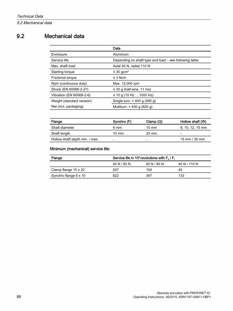
9.2 Mechanical data
DataEnclosure AluminumService life Depending on shaft type and load – see following tableMax. shaft load Axial 40 N, radial 110 NStarting torque ≤ 30 gcm2
Frictional torque ≤ 3 NcmRpm (continuous duty) Max. 12,000 rpm Shock (EN 60068-2-27) ≤ 30 g (half-sine, 11 ms)Vibration (EN 60068-2-6) ≤ 10 g (10 Hz ... 1000 Hz)Weight (standard version)Net (incl. packaging)
Single turn: ≈ 400 g (590 g)Multiturn: ≈ 430 g (620 g)
Flange Synchro (F) Clamp (Q) Hollow shaft (W)Shaft diameter 6 mm 10 mm 8, 10, 12, 15 mmShaft length 10 mm 20 mm -Hollow shaft depth min. / max. - - 15 mm / 30 mm
Minimum (mechanical) service life:
Flange Service life in 108 revolutions with Fa / Fr
40 N / 60 N 40 N / 80 N 40 N / 110 NClamp flange 10 x 20 247 104 40Synchro flange 6 x 10 822 347 133
Technical Data9.2 Mechanical data
Absolute encoders with PROFINET IO 88 Operating Instructions, 06/2015, 6SN1197-0AB11-0BP1

9.3 Environmental conditions
DataWorking temperature range - 40 ... + 85 °CStorage temperature range - 40 ... + 85 °CRelative humidity Up to 98% (without condensation) Degree of protection DIN 40050 Housing side: IP 67
Shaft side: IP 64
Technical Data9.3 Environmental conditions
Absolute encoders with PROFINET IO Operating Instructions, 06/2015, 6SN1197-0AB11-0BP1 89

Technical Data9.3 Environmental conditions
Absolute encoders with PROFINET IO 90 Operating Instructions, 06/2015, 6SN1197-0AB11-0BP1

Mechanical Drawings 1010.1 Synchro flange
Overview
Figure 10-1 Syncro flange
Absolute encoders with PROFINET IO Operating Instructions, 06/2015, 6SN1197-0AB11-0BP1 91

10.2 Clamp flange
Overview
Figure 10-2 Clamp flange
Mechanical Drawings10.2 Clamp flange
Absolute encoders with PROFINET IO 92 Operating Instructions, 06/2015, 6SN1197-0AB11-0BP1

10.3 Hollow shaft
Overview
Figure 10-3 Hallow shaft
NoteMounting instructions
The clamp ring should only be tightened after the shaft of the drive element has been inserted into the hollow shaft.
The diameter of the hollow shaft can be reduced to 12 mm, 10 mm or 8 mm using a reducing adapter (these are included in the scope of supply). These reducing adapters are simply inserted into the hollow shaft.
Maximum radial and axial misalignment of the drive shaft:
Axial Radialstatic ± 0.3 mm ± 0.5 mmdynamic ± 0.1 mm ± 0.2 mm
Mechanical Drawings10.3 Hollow shaft
Absolute encoders with PROFINET IO Operating Instructions, 06/2015, 6SN1197-0AB11-0BP1 93

Mechanical Drawings10.3 Hollow shaft
Absolute encoders with PROFINET IO 94 Operating Instructions, 06/2015, 6SN1197-0AB11-0BP1

Accessories 1111.1 Accessories and Documentation
Description TypeSpring disk coupling 6 mm/ 6 mm
6 mm/ 5 mm6FX2001-7KF106FX2001-7KF06
Connecting cable, Ethernet PAM4/RJ45 Straight 5 m 6XV1871-5TH50Connecting cable, power PAM5 2 m Shielded 6XV1801-5DH50Coupling ** Drilling: Ø 10 mm 6FX2001-7KS10Clamp disk ** Set = 1 pcs 6FX2001-7KP01Operating Instructions * Installation / configuration manual,
English6SN1197-0AB11-0BP0
GSDML file *
Additional information about the accessories is provided in the Catalog:
"SIMOTION & SINAMICS PM 21", Part 7: Measuring systems
* This can be downloaded free of charge from MDM, see: Hotline and Internet addresses (Page 3)
** Can only be used for full shaft
We do not assume responsibility for technical inaccuracies or omissions. Specifications are subject to change without notice.
Absolute encoders with PROFINET IO Operating Instructions, 06/2015, 6SN1197-0AB11-0BP1 95

11.2 Ordering descriptionThe order designation consists of a combination of alphanumeric characters, the machine-readable product designation MLFB. When placing an order, it is sufficient just to specify the unique MLFB.
The MLFB consists of three blocks that are separated by hyphens. The first block has seven characters and designates the product family and size of the primary or secondary section. In the second block, further design features are encoded, such as length and speed. The third block is provided for additional data.
Note that not every theoretical combination is possible in practice.
Accessories11.2 Ordering description
Absolute encoders with PROFINET IO 96 Operating Instructions, 06/2015, 6SN1197-0AB11-0BP1

11.3 Models / ordering description
Overview
Accessories11.3 Models / ordering description
Absolute encoders with PROFINET IO Operating Instructions, 06/2015, 6SN1197-0AB11-0BP1 97

Accessories11.3 Models / ordering description
Absolute encoders with PROFINET IO 98 Operating Instructions, 06/2015, 6SN1197-0AB11-0BP1

Appendix AA.1 Glossary
Term Explanations10Base-T Transmission line with 10 Mbit data transmission rate.100Base-T Transmission line with 100 Mbit data transmission rate.Auto crossing Allow to use straight or crossover wiring.Auto negotiation Is an Ethernet procedure by which two connected devices choose common transmission param‐
eters, such as speed and duplex mode.AWP User program running on the PLC or SIMOTION.Baud rate Transmission rate; it display the transmission bits per second.Binary Numeric system with value 0 or 1.BMP PROFIdrive "Bau Mode Parameter Access" channel defined in PROFIdrive Profile, standard for
online Parameter access (Access Point Data Record 0xB02E).CAT5 Terminations for transmission rates up to 100 Mbit.DCP.Hello On Fast Start up the encoder will register to the IO-Controller with the "DCP.Hello"-Service.EMC Electromagnetic compatibility, there are rules to verifying devices.Ethernet Ethernet is a computer network technology based on frames.Endless shaft (Rotary axis) solves the problem with non binary values for revolutions.Fast Ethernet Transmission technology with 100 Mbit transmission rate.Fast starting Optimized start time for PROFINET (< 1s).Flash Internal memory, saved data will be available after power down.GSDML Generic Station Description Markup Language: XML based description language. Contains all
available parameters, classes, … Generic Station Description Markup Language: XML based description language. Contains all available parameters, classes.
Implicit Messaging IO Connection: communication between IO-controller and IO-device.IP address Allows a computer to be logically addressed in a network.IRT Isochronous Real Time (Ethernet).LLDP Link Layer Discovery Protocol.MAC address Worldwide explicit address of a device. The encoder uses three MAC Addresses: one for internal
interface and two for the ports. The basic MAC Address is stamped on the type plate.Mbit Transmission rate or baud rate, million bits per second.MAP Module Access Point. This MAP submodule contains at least the mandatory Parameter Access
Point (PAP) which is mapped to a dedicated Record Data Object.OSI-Model The Open System Interconnection reference model is a open layer model for the organization of
a communication.PDEV Physical device. Not all PLCs support several sub slots. Then select in the product tree Customized
- otherwise ProfileV4.x.PZD Process Data: Process data part of a PPO.Rotary axis See -> Endless shaft.Switch A switch is an electronic device to connect computers e.g. network segments in a local network.
Unlike a hub, a switch uses stacks to avoid network collisions.
Absolute encoders with PROFINET IO Operating Instructions, 06/2015, 6SN1197-0AB11-0BP1 99

Term ExplanationsTCP The Transmission Control Protocol is a connection orientated transmission protocol, in a network.UDP User Datagram Protocol is used to send data that does not need to be transferred in a reliable
way.
AppendixA.1 Glossary
Absolute encoders with PROFINET IO 100 Operating Instructions, 06/2015, 6SN1197-0AB11-0BP1

A.2 Additional literature
[1] Encoder ProfileProfile EncoderVersion 4LEER1, December 2008PROFIBUS Nutzerorganisation e.V.Haid- und Neu-Strasse 7, D-76131 Karlsruhehttp://www.profibus.comOrder number 3LEER162
[2] PROFIdrive ProfileProfile Drive TechnologyVersion V4LEER1, May 2006,PROFIBUS Nutzerorganisation e.V.Haid-und-Neu-Strasse 7, D-76131 Karlsruhehttp://www.profibus.comOrder number 3LEER172
[3] SIMOTION SCOUT Communication System Manual [3a] Chapter: PROFIdrive; PROFIdrive overview [3b] Chapter: PROFIdrive; acyclic communication (Base Mode Parameter Access) [3c] Chapter: PROFIdrive; acyclic communication (Base Mode Parameter Access); system
commands in SIMOTION [3d] Chapter: PROFIdrive; acyclic communication (Base Mode Parameter Access); rules
for the use of _readRecord und _writeRecord
AppendixA.2 Additional literature
Absolute encoders with PROFINET IO Operating Instructions, 06/2015, 6SN1197-0AB11-0BP1 101

AppendixA.2 Additional literature
Absolute encoders with PROFINET IO 102 Operating Instructions, 06/2015, 6SN1197-0AB11-0BP1


![PROFINET IO bus interface, PROFINET IO [BU 2400]...PROFINET IO bus interface – Supplementary manual options for NORD - Frequency Inverters 6 BU 2400 en-4319 List of illustrations](https://static.fdocuments.us/doc/165x107/60f041c8833abd61704a1c6f/profinet-io-bus-interface-profinet-io-bu-2400-profinet-io-bus-interface-a.jpg)