Operating Guide 1000 Series Dispensers - unifr.ch · Operating Guide 1000 Series Dispensers ......
28
Operating Guide 1000 Series Dispensers ® A NORDSON COMPANY In the US: 800-556-3484 In the UK: 0800 585733 In Mexico: 001-800-556-3484 1000XL 1000D •
-
Upload
truongduong -
Category
Documents
-
view
215 -
download
0
Transcript of Operating Guide 1000 Series Dispensers - unifr.ch · Operating Guide 1000 Series Dispensers ......

Operating Guide1000 Series Dispensers
®
A NORDSON COMPANY
In the US: 800-556-3484 In the UK: 0800 585733 In Mexico: 001-800-556-3484
1000XL 1000D•

The 1000 Series dispensers provide years of trouble-free, produc-tive service. This Operating Guide will help you maximize theusefulness of your new dispenser.
Please spend a few minutes to become familiar with the controls andfeatures of your new dispenser. Follow our recommended testingprocedures. Review the helpful information we have included basedon over 30 years of industrial dispensing experience.
Most questions you will have are answered in this Guide. However,if you need assistance, please do not hesitate to contact EFD or yourauthorized EFD distributor.
In the US , call 800-556-3484.
In Mexico, call 001-800-556-3484.In the UK, ring free 0800 585733.
Introduction
The EFD PledgeWe pledge that you will be completely satisfied with our products.We endeavor to ensure that every EFD product is produced to ourno-compromise quality standards.
If you feel that you are not receiving all the support you require,or if you have any questions or comments, I invite you to write or callme personally.
Our goal is to build not only the finest equipment and components,but also to build long-term customer relationships founded onsuperb quality, service, value and trust. John Carter, President
☎

Getting Started ............................................................................. 4Specifications
First Steps .................................................................................... 5Unpacking the Dispenser and Activating your Ten Year No-fault Warranty
1000XL - Hookup ...................................................................... 6-7
1000XL - Setup for Testing ....................................................... 8-9
1000D - Hookup .................................................................... 10-11
1000D - Setup for Testing ..................................................... 12-13
Testing the 1000 Series Dispensers ..................................... 14-15Making Timed Deposits
Changing Deposit Size
Drawing Stripes
ULTRA Dispensing System................................................... 16-17
How to Use the Vacuum Control ........................................... 18-191000XL only
Loading the Barrel Reservoirs............................................... 20-21
Now, Test Your Fluid .................................................................. 22
Troubleshooting ......................................................................... 23
1000XL and 1000D Schematic & Parts ...................................... 24
1000 Series Programmable Timer ............................................. 25
Suggestions & Reminders .......................................................... 26
Components Reorder ................................................................. 27
Ten Year No-fault Warranty ....................................................... 28
Meets applicable CSA and CE requirements.
Reference CSA LR File Number 84105
Contents
This manual is for the express and sole use of EFDdispenser purchasers and users, and no portion of thismanual may be reproduced in any form.
EFD, ULTRA System, LV Barrier, SmoothFlow,ZeroDraft, SafetyLok, SnapLok and DispenStand aretrademarks of EFD Inc. ©2004 EFD Inc.

We have organized this Guide to provide setup and testing proce-dures for the 1000XL and 1000D dispensers.
If you have the 1000XL, first review pages 6 - 9 which illustrate howto hook up the dispenser and what the controls do.
For the 1000D, review pages 10 - 13.
Next, pages 14 - 15 show how to dispense the thick, paste-like testmaterial included in the Test Kit. These instructions are common toboth 1000 Series dispensers.
Finally, pages 18 - 19 illustrate how to dispense low-viscosity liquidusing the vacuum control provided on the 1000XL.
The rest of the information in this Guide applies to both of the 1000Series dispensers.
1000 Series SpecificationsInput voltage: Selectable
100/120/220 VAC50/60 Hz 16/13 VA
Internal voltage: 24 VDC
Foot-pedal voltage: 9 VDC
Air input: 80 to 100 psi(5.5 to 6.9 bar)
Air output: 0 to 100 psi(0 to 6.9 bar)
Cycle rate: > 600/minute
Time repeat: ±0.1%
Initiation: maintained or momentary
Time Range: programmable (seconds)0.005 to 0.04 sec.0.01 to 1.0 sec.0.1 to 10 sec.0.2 to 20 sec.0.3 to 31 sec.
1000XL10⅜ x 8½ x 2⅝ 5 lb 12 oz26.4 x 21.6 x 6.7 cm 2.63 kg
1000D8⅝ x 8½ x 2⅝ 4 lb 12 oz21.9 x 21.6 x 6.7 cm 2.18 kg
Getting Started

First: Unpack and use the checklist enclosed with the Dispenser Kitto identify all items. If there is any discrepancy, please call usimmediately.
Second: Power and compressed plant air should be available wherethe dispenser is to be set up. Air pressure should be between 80 and100 psi (5.5 to 6.9 bar). (Bottled nitrogen can be used.) If you arenot using an EFD five-micron filter regulator #2000F755, be certainyour plant air is properly filtered and dry.
Check voltage label to be certain it agrees with the available power.
Third: Now is a good time to ACTIVATE your extended Ten YearNo-fault Warranty. Please fill in and return the postage-paidWarranty card. Or, if you prefer, call the appropriate toll-free numberlisted below, provide the serial number of your dispenser andrespond to a few short questions.
In the US , call 800-556-3484.
In Mexico, call 001-800-556-3484.In the UK, ring free 0800 585733.
☎
First Steps

❻
❶
❺
Check voltage labelon dispenser
Plant air, 125 psi maximum toregulator. Output from regulatorshould be a minimum of 80 psi,maximum of 100 psi.
❷
❸
❹
Bluetest fluid
Male quick-connect,insert and twist to lock
❼
Powercord
Air inputhose
Foot pedalassembly
Adapterassembly 1000XL

1000
XL
1000XL -- Hookup❶ Connect the air input hose to a plant air source. Set plant air supply
within 80 to 100 psi (5.5 to 6.9 bar). Where required, use an EFDfive-micron filter regulator #2000F755 (see Warranty).
❷ Attach the air input hose coupling to the dispenser. Pull back metalring to attach to dispenser.
❸ Plug in the polarized foot pedal connector.
❹ Check the voltage label on the input voltage selector cartridge. Tochange the voltage, remove the voltage selector from the car-tridge, rotate it and position the correct voltage to show through thecartridge window. Replace the cartridge into the power cordreceptacle and insure that both sides snap securely into position.
Install the power cord.
❺ Attach the 10cc barrel pre-filled with blue, nontoxic test fluid(included with the dispenser) to the 10cc adapter head.
❻ Take the 10cc adapter assembly (#5150 on the adapter head) andinsert the black, male quick-connect into the air output fitting on thefront panel and turn clockwise to lock. Place the barrel in the barrelstand.
❼ During the initial testing, you will not use the vacuum control. Keepthis control shut off (turned completely clockwise—do not force).
220
120
100
Spare fuse
Voltage valueCartridge window(check voltage indicated)

CONTROLS and CONNECTIONS
54
Voltage selector andfuse cartridge
Air inputVacuum transducerair exhaust port
Cover screw
Power inputreceptacle
Barrelvacuum control Vacuum gauge
Air outputquick-connect
Powerswitch
2 1
Air pressure regulator
3
6Timerbypass
7
Time controlAir gauge
Cycle LED
220

1000
XL
1000XL -- Setup for TestingPower switch 6 should be off.
The amount of material dispensed each cycle depends on thecombination of air pressure, time of air pulse, viscosity of materialand dispensing tip size.
The first step is to remove the tip cap from the pre-filled barrel of bluetest material (twist and pull). Replace it with an 18 gage (green)tapered dispensing tip. Press the tip on and twist clockwise to lock.
Pull out air pressure regulator knob 1 until it "clicks" into the unlockedposition. Turn clockwise to adjust the air pressure to 30 psi (2.1 bar)for the initial tests.
Always set the pressure desired by turning the air regulator knob 1clockwise. To reduce the pressure, turn the knob counterclockwiseuntil the air gauge 2 reads a lower pressure than desired. Thenincrease and stop at desired pressure. Push knob in to lock.
Set the time control 3 to #7. Dispense cycle time increases from0.01 second minimum to 1.0 second as knob is turned clockwise.
Be sure vacuum control 4 is shut off. In the initial tests, the vacuumpressure gauge 5 will indicate zero pressure. You may notice theneedle on this gauge (when turned off) will jump slightly after eachcycle. This is normal.
Press power switch 6 to turn on the dispenser. It will light green.
Press timer bypass switch 7. It will light yellow. In this operationmode, the timer will be bypassed to fill the dispensing tip before youbegin testing. A continuous flow of material will occur as long as thefoot pedal is pressed.
Please continue to page 14 for test procedures.

❶
Plant air, 125 psi maximum toregulator. Output from regulatorshould be a minimum of 80 psi,maximum of 100 psi.
❷
❺
Check voltage labelon dispenser
❸
❻
Bluetest fluid
❹
Male quick-connect,insert and twist to lock
Powercord
Air inputhose
Foot pedalassembly
Adapterassembly
1000D
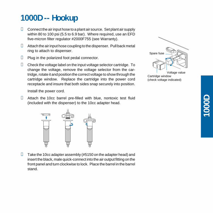
1000D -- Hookup❶ Connect the air input hose to a plant air source. Set plant air supply
within 80 to 100 psi (5.5 to 6.9 bar). Where required, use an EFDfive-micron filter regulator #2000F755 (see Warranty).
❷ Attach the air input hose coupling to the dispenser. Pull back metalring to attach to dispenser.
❸ Plug in the polarized foot pedal connector.
❹ Check the voltage label on the input voltage selector cartridge. Tochange the voltage, remove the voltage selector from the car-tridge, rotate it and position the correct voltage to show through thecartridge window. Replace the cartridge into the power cordreceptacle and insure that both sides snap securely into position.
Install the power cord.
❺ Attach the 10cc barrel pre-filled with blue, nontoxic test fluid(included with the dispenser) to the 10cc adapter head.
❻ Take the 10cc adapter assembly (#5150 on the adapter head) andinsert the black, male quick-connect into the air output fitting on thefront panel and turn clockwise to lock. Place the barrel in the barrelstand.
1000
D
220
120
100
Spare fuse
Voltage valueCartridge window(check voltage indicated)

CONTROLS and CONNECTIONS
Cover screw
Air outputquick-connect
Powerswitch
2 1
Air pressure regulator
3
4Timer bypass5
Time controlAir gauge
CycleLED
220
Air inputSolenoid Power inputreceptacle
Foot pedal receptacle
Voltage selectorand fuse cartridge

Power switch 4 should be off.
The amount of material dispensed each cycle depends on thecombination of air pressure, time of air pulse, viscosity of materialand dispensing tip size.
The first step is to remove the tip cap from the pre-filled barrel of bluetest material (twist and pull). Replace it with the 18 gage (green)tapered dispensing tip. Press the tip on and twist to lock.
Pull out air pressure regulator knob 1 until it "clicks" into the unlockedposition. Turn clockwise to adjust the air pressure to 30 psi (2.1 bar)for the initial tests.
Always set the pressure desired by turning the air regulator knob 1clockwise. To reduce the pressure, turn the knob counterclockwiseuntil the air gauge 2 reads a lower pressure than desired. Thenincrease and stop at desired pressure. Push knob in to lock.
Set the time control 3 to #7. Dispense cycle time increases from 0.01second minimum to 1.0 second as knob is turned clockwise.
Press power switch 4 to turn on the dispenser. It will light green.
Press timer bypass switch 5. It will light yellow. In this operationmode, the timer will be bypassed to fill the dispensing tip before youbegin testing. A continuous flow of material will occur as long as thefoot pedal is pressed.
Please continue to page 14 for test procedures.
1000D -- Setup for Testing
1000
D
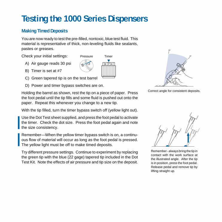
Making Timed Deposits
You are now ready to test the pre-filled, nontoxic, blue test fluid. Thismaterial is representative of thick, non-leveling fluids like sealants,pastes or greases.
Check your initial settings:
A) Air gauge reads 30 psi
B) Timer is set at #7
C) Green tapered tip is on the test barrel
D) Power and timer bypass switches are on.
Holding the barrel as shown, rest the tip on a piece of paper. Pressthe foot pedal until the tip fills and some fluid is pushed out onto thepaper. Repeat this whenever you change to a new tip.
With the tip filled, turn the timer bypass switch off (yellow light out).
Use the Dot Test sheet supplied, and press the foot pedal to activatethe timer. Check the dot size. Press the foot pedal again and notethe size consistency.
Remember—When the yellow timer bypass switch is on, a continu-ous flow of material will occur as long as the foot pedal is pressed.The yellow light must be off to make timed deposits.
Try different pressure settings. Continue to experiment by replacingthe green tip with the blue (22 gage) tapered tip included in the DotTest Kit. Note the effects of air pressure and tip size on the deposit.
Correct angle for consistent deposits.
Remember - always bring the tip incontact with the work surface atthe illustrated angle. After the tipis in position, press the foot pedal.Release pedal and remove tip bylifting straight up.
Testing the 1000 Series Dispensers
TimerPressure
230 7 68
45°
80°

Changing Deposit Size, Drawing Stripes
The dot size is determined by the tip diameter, the air pressureoutput setting and the pulse time. For large dots, use a large tip,higher pressure and more time. Normally, you want to use as shorta time pulse as possible. To increase the dot size, slightly increasethe air pressure output, or increase the tip size, or both.
Use the convenient Dot Test sheet included.
Dot Test with Green Tapered Tip
First, follow the settings illustrated on the left, and you will get dotsabout the sizes shown. Try other times and pressures to see howeasy it is to get just the dot size you want.
Dot Test with Blue Tapered Tip
These tests show the effect of using a smaller diameter tip.
Replace the green tip with the blue (22 gage) tapered tip. Now, turnon the timer bypass switch and press the foot pedal to fill the tip.Then, turn off the timer bypass switch (yellow light out) and press thefoot pedal.
Making Stripes
Keep the settings at Test G (shown to the left) and turn on the timerbypass switch (yellow light on). With the tip in contact with the testsheet, press and hold down the foot pedal while drawing a line forbeading or striping.
Blue Tip Settings
Test Pressure Time Dot Size
F 30 psi #6
G 20 psi #6
H 20 psi #3
I 15 psi #3
J 10 psi #3
Green Tip Settings
Test Pressure Time Dot Size
A 30 psi #7
B 20 psi #7
C 20 psi #3
D 15 psi #3
E 10 psi #3

If you dispense thick fluids, several problems mayoccur. First, the repetitive air cycles can boretunnels through non-leveling fluids, causingspitting and inconsistent deposits. Second, thickfluids contain trapped air that leads to droolingand oozing.
These problems are eliminated by using theSmoothFlow™ piston. That's because the whitepistons prevent tunneling by providing a barrier tothe pulsed-air cycles, and prevent oozing byresponding to the pressure of trapped air with aslight suck-back movement after the dispensecycle.
The white piston is used for most fluids.
However, if you are applying RTV silicone andfind that the piston bounces and causes stringing,switch to the orange, flat wall piston.
The SmoothFlow™ pistons make barrel fillingeasier, too. As you load the fluid in, air is trappedin the bottom and throughout the fluid. Simplyinsert a SmoothFlow™ piston and gently pressdown on the fluid as far as possible. This actionforces out most of the air and results in consistentdeposits.
Advanced Dispensing System
For Thick Fluids
Air PressureOFF
Air PressureON
No dripor ooze.
TM

For Thin Fluids
Fumescannotescape.
SmoothFlow™ pistonprevents fluid backflow.
For Watery-thin Fluids
Blue LV Barrier™ forimproved control ofvery low viscosityfluids.
Note: If you choose not to use the piston,please refer to page 19 for instructions.
If you use low to medium viscosity fluids, the whiteSmoothFlow™ piston has several advantages.
First, vacuum adjustment is much less sensitive.Second, the piston prevents fumes from the fluidbeing exhausted into the work environment. Third,the piston prevents fluid backflow into the dis-penser if the barrel is inadvertently turned upsidedown. Fourth, using the piston makes it easy andsafe to change tips without dripping.
Note: If you use watery-thin fluids such as solvents,cyanoacrylates and anaerobics, specify the ULTRASystem™ with the blue LV Barrier™. Available onlyin 10cc size.

How to Use the Vacuum Control (1000XL only)
InsertSmoothFlow™
piston.
Removeorangeend cap.
Removetip cap.
The vacuum control allows low viscosity fluids, even water, to beconsistently dispensed without dripping between cycles. The vacuumexerts a negative pressure on the fluid in the barrel and preventsdripping.
For these tests, you will use the test barrel with the clear fluid.
1. While holding the barrel upright in one hand, remove the orangeend cap and insert the white SmoothFlow™ piston. Carefullypress the piston down to contact the liquid.
Be sure to push it far enough to remove all air, but not into thefluid, since this will force the fluid up along the sides of the piston.
2. Attach the barrel to the 10cc adapter. Snap the safety clip tightlyclosed to prevent any dripping or bubbling. Remove the tip capand attach the 25 gage (red) tip.
3. Set air pressure at 5 psi and timer to #5, then turn on timer bypass.
4. With the barrel pointing downward over a container, press thefoot pedal to fill the tip.
5. Turn off the timer bypass switch (yellow light out).
6. If a drop begins to form at the end of the tip, slowly turn thevacuum control knob counterclockwise to stop the drop fromgrowing. Wipe the tip and slowly adjust vacuum. Normally, only1 to 2 psi of vacuum pressure is necessary.
7. Take the barrel and place the tip on the test sheet. Press the footpedal and release. Check the deposit. Increase or decrease byadjusting pressure or time.

If you choose not to use the piston, please follow these instruc-tions carefully:
1. While holding the barrel upright in one hand, twist on anorange tip cap. Using the small funnel supplied, fill about2/3 full with your liquid.
2. Open the safety clip and attach the barrel to the 10cc adapter.
3. Close the safety clip as tight as possible.
4. Increase vacuum by turning vacuum control knob counter-clockwise and set to 1.5 on the vacuum pressure gauge.
5. Then, without tipping the barrel upside down, remove the tipcap and attach the 25 gage (red) tip.
6. Open the safety clip. Your material may begin to bubble.Reduce vacuum by turning vacuum control knob clockwise.
7. If a drop begins to form at the end of the tip, slowly turn thevacuum control knob counterclockwise to stop the drop fromgrowing. Wipe the tip and adjust vacuum as necessary.
Now the fluid is in proper balance. It does not bubble or drip.
Repeat tests as before, keeping the air pressure low and adjust-ing the time for different deposit sizes. Contact EFD if you haveany questions.
In the US , call 800-556-3484.
In Mexico, call 001-800-556-3484.In the UK, ring free 0800 585733.
☎
Do not tip the barrel upside downor lay flat. This will cause theliquid to run into the dispenser.
When changing tipsor attaching a tip cap,snap the safety clipcompletely closed toprevent any drippingor bubbling.
Three things to rememberIf you do not use the piston whendispensing thin fluids:
Use an EFD filter trap (#1000FLT-Y).This filter trap will impede the flowshould the low viscosity liquid besucked back towards the dispenser.
Open
Closed

Loading the Barrel ReservoirsCaution: Do not completely fill barrels. The optimum fill is a maximum2/3 of the barrel capacity and 1/2 of the barrel capacity when usingthe LV Barrier™.
If the fluid you are dispensing is pourable, take the barrel, twist on atip cap and pour your fluid in. If appropriate, insert the SmoothFlow™
piston (see page 13). Carefully press the piston down until it contactsthe fluid. The barrel is now ready for use.
If you are dispensing solvents, cyanoacrylates or anaerobics, usethe LV Barrier™. Place barrier in the top of the barrel reservoir. Allowair between barrier and fluid. Do not contact the barrier to the fluid.
If your fluid is thick or non-leveling, you can spoon it into the barrelwith a spatula. Or, if the fluid comes packed in a 1/10 gallon cartridge,try loading the barrel with a caulking gun. Then, press in theSmoothFlow™ piston to move the fluid to the bottom of the barrel andto remove trapped air.
2/3MaximumFill
WhiteSmoothFlow™
piston.
LV Barrier™
Fill procedure forwatery-thin fluids.
1/2 maximum fill
Fill procedure withcaulking gun.
Air
Fill procedure forpourable fluids.

EFD offers productive alternatives to traditional barrel-loading meth-ods. Here are a few suggestions that can help keep your work areaclean, save time and reduce the chance of entrapped air in the fluid.
1. You could use the EFD #920BL barrel loader. Pack the fluid intothe 12 ounce cartridge as shown. Then place the pre-filledcartridge into the barrel loader. Using air pressure, the barrelloader fills the barrel (with piston) from the bottom up.
If the fluid comes packed in a 1/10 gallon (300 ml.) caulking typecartridge, use the EFD #930BL barrel loader.
2. If you receive frozen epoxies or other fluids in medical typesyringes with a manual plunger, request our luer-to-luer fitting#2160 to transfer the material.
Please call an EFD Product Specialist for additional assistance.
Filling the cartridgefor the barrel loader.
2/3MaximumFill
EFD #920BL Barrel Loader(Specify #930BL for pre-filled 1/10 gallon caulking tubes)
Barrel Rack#905BR for 3cc and 5cc barrels#910BR for 10cc, 30cc and 55cc barrels
#2160 Luer-to-luer fitting

Barrel Reservoir Selection
Remember, each barrel must use the proper size adapter head. Fivesizes of barrels and four sizes of adapter heads (30cc and 55ccbarrels use the same size adapter head) are provided with thisdispenser—3cc, 5cc, 10cc, 30cc and 55cc.
The most comfortable size barrel is the 10cc. But if you plan to makevery small dots, we recommend the 5cc or even the 3cc size. Forlarge dots or encapsulating work, use the 30cc or 55cc size.
If you find you need more reservoir capacity than 55cc, consider the2 1/2, 6 or 12 ounce cartridges. Contact EFD for assistance andspecific recommendations based on your application.
Tip Selection
The EFD 5100 Component Kit included with the dispenser containsa complete selection of disposable tips.
The appropriate tip for your application will increase assemblyproduction. Refer to the enclosed booklet with the Component Kit forhelpful recommendations.
Time and Pressure Settings
When establishing settings for your material, keep the time as shortas possible, the tip as large as possible and air pressure as neededto produce the dot size you require.
Rule of Thumb: Start with a short pulse time. Use the dispensing tipsize appropriate for the size dot required. Vary air pressure. Formore output, gradually increase pressure.
Caution: Use of high air pressure with low viscosity material and asmall gage tip can expel the material some distance.
All components are quality producedin a silicone-free environment by
EFD in the USA.
Now, test your fluid.
RFO
IFI DERCE T
AIR
NISTUD
LE
SU
MadeMadein
U.S.A.U.S.A.

☎
1. Check voltage at wall outlet.
2. Check fuse. Replace #7111E.
3. Unplug from wall, remove top cover, visually inspect for any looseor shorted connections.
1. Switch module must be replaced.
1. Unplug input power cord.
2. Check foot pedal connection, foot pedal and internal switch.
1. Check dispensing tip, barrel and material for possible clogging.
2. Check air gauge to be sure air pressure is not varying.
3. Check to see if there are air bubbles in the material beingdispensed.
1. Check to be sure timer bypass switch is off (yellow light out).
2. Check DIP switch positions (see page 25).
Note: The EFD timer is very reliable. Most questions about the timerare resolved by simply turning the timer bypass switch off (yellowlight out).
1. Use SmoothFlow™ pistons or LV Barriers™ to prevent this. (Seepages 16-17.)
2. If it occurs, attach an empty barrel, put timer bypass switch on, putbarrel in a cup and press the pedal to expel the sucked-back fluid.
3. If problem cannot be corrected, contact an EFD Product Specialistfor assistance. Dispensers can be returned to EFD for repair.
If you have any problems, we will correct them immediately. Pleasedo not hesitate to contact EFD or your authorized EFD distributor.
In the US , call 800-556-3484.
In Mexico, call 001-800-556-3484.In the UK, ring free 0800 585733.
NO POWER
POWER, BUT NO LIGHT
POWER, LIGHT, BUTMACHINE DOES NOT OPERATE
INCONSISTENT DOTS
TIMER SEEMS INOPERATIVE
MATERIAL SUCK-BACK
Troubleshooting

Model 1000D
Model 1000XL
Schematic and Parts1000D and 1000XLReplacement Parts List
1. 2024-160 1/4" OD x .160" ID tubing
2. 2-2031-1000 Transformer assembly multi input
3. 2-2017A-24XL Foot pedal receptacle
4. 2169 Fitting 1/8 NPT x 1/8 NPT elbow brass
5. 2088 Fitting 1/8 NPT x 1/4 barb brass
6. 2-2006-24PR Programmable timer
7. 2001C 0 to 100 psi (0 to 7.0 bar) gauge
8. 2081A Male mini air-coupler panel mount
9. 2087 Fitting 1/8 NPT x 1/4 barb elbow brass
10. 2-2007-XL Potentiometer assembly
11. 2008A Time control knob
12. 2-2003-1000 24 VDC solenoid assembly
13. 2010-A24 Power switch 115 VAC
14. 2-2011-24 1000XL timer bypass switch assembly
15. 2019 Dispenser end panel
16. 2-2004B Quick-connect assembly
17. 2089 Fitting 1/8 NPT x 1/4 barb tee brass
18. 7111E Fuse .160A
19. 2014XL Input power receptacle
20. 2002SCR Replacement screen for regulator*
21. 2009-A24 Power cord American*
22. 2009-E24 Power cord European*
23. 2015A Foot pedal assembly*
24. 2033 Dispense indicator LED*
25. 1000INP-AKIT Air input hose*
26. 2-2002 1000D regulator assembly 0 to 100 psi (0 to 7.0 bar)
27. 2-2002-XL 1000XL regulator assembly 0 to 100 psi(0 to 7.0 bar)
28. 2001B 0 to 15 psi (0 to1.0 bar) gauge
29. 2178 Fitting 1/8 NPT x 1/4 barb elbow brass
30. 2-2170LV Vacuum transducer assembly
31. 2-2176-XL Barrel vacuum control assembly
32. 2036 Fitting 1/8 NPT x 1/4 barb brass
33. 2083 Gauge restrictor
34. 2084 Air restrictor
35. 7108 1000D muffler
* Not Shown
Input AirRegulated AirVacuum
31
34
2
8
19
2728
517
7
15
32
9
9
12930
18
3
4
1016
1413
1
29
33
11
29
6
1413
17
19
2
26
8
7
5
15
912
35
6
9
18
4
10
16
3
1
11

The heart of each 1000 Series dispenser is the EFD advanced solid-state, digital timer with programmable time ranges and choice ofMomentary (press the foot pedal once) or Maintained (hold footpedal down during time cycle) initiation modes.
This unique timer is located inside the dispenser. To access, removethe two cover screws and slide the cover off the dispenser.
Caution: Always disconnect the power cord before removing thecover.
The DIP switch that controls the timer has been set at the factory fora time range of 0.01 to 1.0 second, with the initiation set toMOMENTARY contact. (See top diagram.)
Experience shows this is the most often used initiation mode andtime range.
For larger deposits that require longer time, it may be advantageousto set the initiation to MAINTAINED contact. The operator must thenkeep the foot pedal pressed throughout the time cycle.
Four time ranges are provided so that you can have fine-timeadjustment in the range you select.
For extremely small dots of low viscosity, watery fluids, you may wantto select the 0.005 to 0.04 second range. For slow filling, a longertime range will provide the time that's needed for flow control.
DIP Switch Settings
④ ON = Maintained pedal contact
④ OFF = Momentary pedal contact
ON
1 2 3 4ON
ON
ON
ON
ON
1 2 3 4
1 2 3 4
1 2 3 4
1 2 3 4
1 2 3 4
② ④ ON0.1-10 secondsMaintained
① ② ③ ON0.3-31 secondsMomentary
① ② ③ OFF0.005-0.04 secondMomentary
③ ON0.01-1.0 secondMomentary
② ON0.1-10 secondsMomentary
① ON0.2-20 secondsMomentary
Programmable Timer
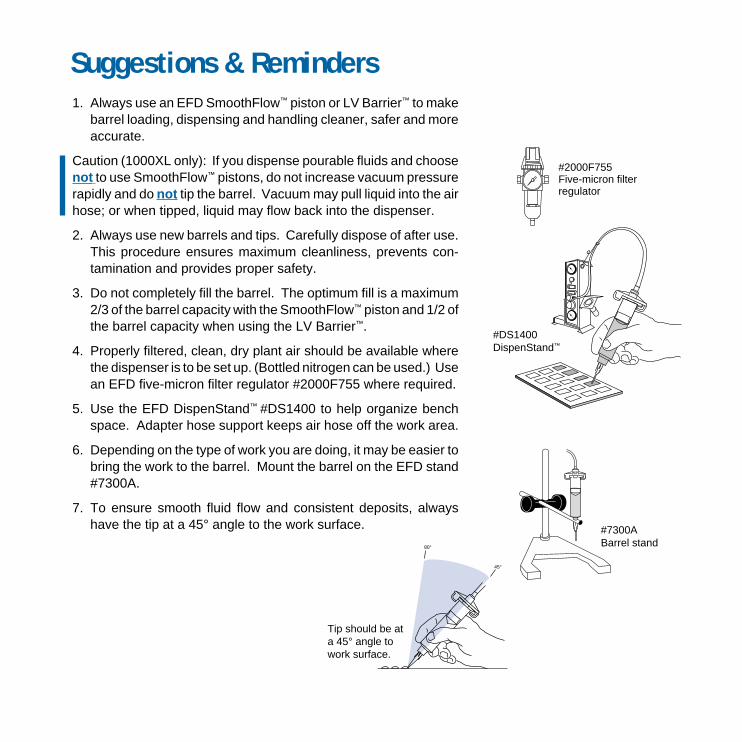
#2000F755Five-micron filterregulator
1. Always use an EFD SmoothFlow™ piston or LV Barrier™ to makebarrel loading, dispensing and handling cleaner, safer and moreaccurate.
Caution (1000XL only): If you dispense pourable fluids and choosenot to use SmoothFlow™ pistons, do not increase vacuum pressurerapidly and do not tip the barrel. Vacuum may pull liquid into the airhose; or when tipped, liquid may flow back into the dispenser.
2. Always use new barrels and tips. Carefully dispose of after use.This procedure ensures maximum cleanliness, prevents con-tamination and provides proper safety.
3. Do not completely fill the barrel. The optimum fill is a maximum2/3 of the barrel capacity with the SmoothFlow™ piston and 1/2 ofthe barrel capacity when using the LV Barrier™.
4. Properly filtered, clean, dry plant air should be available wherethe dispenser is to be set up. (Bottled nitrogen can be used.) Usean EFD five-micron filter regulator #2000F755 where required.
5. Use the EFD DispenStand™ #DS1400 to help organize benchspace. Adapter hose support keeps air hose off the work area.
6. Depending on the type of work you are doing, it may be easier tobring the work to the barrel. Mount the barrel on the EFD stand#7300A.
7. To ensure smooth fluid flow and consistent deposits, alwayshave the tip at a 45° angle to the work surface.
Suggestions & Reminders
45°
80°
#DS1400DispenStand™
#7300ABarrel stand
Tip should be ata 45° angle towork surface.

ULTRA System™ Dispensing ComponentsFor complete selection and technical details, please refer to EFD Catalog and price list.
Smooth-flow tapered tipsMolded polyethylene with UV block. Packaged(50) tips per see-through box with covers for easypart identification.
gage ID tapered color
14 .063" 5114TT-B olive16 .047" 5116TT-B grey18 .033" 5118TT-B green20 .023" 5120TT-B pink22 .016" 5122TT-B blue25 .010" 5125TT-B red
General-purpose precision tipsAll EFD dispensing tips incorporate the uniqueSafetyLok™ color-coded polypropylene hubs.Packaged (50) tips per see-through box for easypart identification.
gage ID 1/2" length hub color
14 .061" 5114-B olive15 .054" 5115-B amber18 .033" 5118-B green20 .024" 5120-B pink21 .020" 5121-B purple22 .016" 5122-B blue23 .013" 5123-B orange25 .010" 5125-B red27 .008" 5127-B clear30 .006" 5130-B lavender
Barrel adapter assembliesMolded one-piece, yellow, SnapLok™ adapterhead with Buna N O-ring, flexible 5/32" ODhose, male quick-connect and safety clip.
size with 3-ft hose with 6-ft hose
3cc 1000Y5148 1000Y5148-65cc 1000Y5149 1000Y5149-610cc 1000Y5150 1000Y5150-630cc/55cc 1000Y5152 1000Y5152-6
ULTRA System™ barrels /pistonsIndustrial-grade ZeroDraft™ barrels and whiteSmoothFlow™ pistons are molded silicone-freeby EFD. Each box contains the same quantityof ZeroDraft™ barrels and white SmoothFlow™
pistons. UV-block light-block sets/
size clear amber black box
3cc 5109CP-B 5109AP-B 5109UP-B 505cc 5110CP-B 5110AP-B 5110UP-B 4010cc 5111CP-B 5111AP-B 5111UP-B 3030cc 5112CP-B 5112AP-B 5112UP-B 2055cc 5113CP-B 5113AP-B n/a 15
LV Barrier™ ULTRA SystemDesigned specifically for dispensing low vis-cosity fluids including solvents, cyanoacrylatesand anaerobics. Each box contains the samequantity of ZeroDraft™ barrels and blue LVBarriers™.
size clear sets/box
10cc 5111LV-B 3 0
©2004 EFD Inc. 1000-MAN
Sales and service of EFD dispensers anddispensing components is available throughEFD authorized distributors in over 30 coun-tries. Please contact EFD U.S.A. for specificnames and addresses.
Printed on recycled paper
Unit 14, Apex Business Centre, Boscombe RoadDunstable, Bedfordshire LU5 4SB UKTelephone: (0) 1582 666334 Fax: (0) 1582 664227Freephone: 0800 585733 From Ireland: 00800 8272 9444e-mail: [email protected]
Headquarters: 977 Waterman Avenue, East Providence, RI 02914-1378 USAToll free: 800-556-3484 Mexico: 001-800-556-3484Telephone: +1-401-434-1680 Fax: +1-401-431-0237e-mail: [email protected] www.efd-inc.com
®
A NORDSON COMPANY
All components of EFD dispensers are warranted to the original end user for ten yearsfrom date of purchase.
Within the period of this warranty, EFD will repair or replace free of charge anydefective component, regardless of fault, on return of the part, or the completedispenser, prepaid to the factory.
In no event shall any liability or obligation of EFD arising from this warranty exceedthe purchase price of the equipment. Before using, user shall determine the suitabilityof the product for his intended use, and user assumes all risk and liability whatsoeverin connection therewith. This warranty is valid only when clean, dry, filtered air is used.
EFD makes no warranty whatsoever of merchantability or fitness for a particu-lar purpose. In no event shall EFD be liable for incidental or consequentialdamages.
EFD Ten Year No-fault Warranty