Operating and Maintenance of MAX Air EDGE Data Center Cabinets
53
Operating and Maintenance of MAX Air EDGE Data Center Cabinets
Transcript of Operating and Maintenance of MAX Air EDGE Data Center Cabinets

Operating and Maintenance of MAX Air EDGE Data Center Cabinets
2. Contents
1. Cover2. Contents 33. General Information 43.1 Save these instructions 43.2 Intended users 43.3 Legal information concerning the
operating instructions4
3.4 Copyright 43.5 Revision Rev. 43.6 Proper use 53.7 Precautionary measures 53.8 Safety Instructions 53.9 Symbols in these operating 53.10 instructions 53.11 Important safety instructions 63.12 Service and technical staff 73.13 RoHS compliance 74. Transport and handling 84.1 Scope of delivery of Front Cooler 84.2 Transport 84.3 Unpacking 96. COMPONENTS 116.1 Components of CAN-BREEZE 116.2 Components of Fan Unit 117. UNITS INSTALLATION 127.1 UNIT INSTALLATION 127.1.1 FACTORY-SUPPLIED ACCESSORIES 127.1.2 INITIAL CHECK 138. DRAIN PIPING 138.1 GENERAL 138.2 DRAIN PIPE CONNECTION 149. ELECTRICAL WIRING 169.1 ELECTRICAL WIRING CONNECTION
FOR INDOOR UNIT16
9.2 SETTINGS OF DIP SWITCHES 1710. MAINTENANCE 19
10.1 TAKE OUT THE FILTER 1910.2 CLEAN THE FILTER 2010.3 RESET OF FILTER INDICATION 2011. OUTDOOR UNIT 2111.1 Important Notice 2112. TRANSPORTATION AND HANDLING 2313. BEFORE OPERATION 2314. AUTOMATIC CONTROLS 2415. BASIC TROUBLESHOOTING 2516. NAME OF PARTS OUTDOOR UNIT 2717. UNIT INSTALLATION 2917.1 OUTDOOR UNIT INSTALLATION 2917.2 Installation space 3017.3 Installation place provision 3218. REFRIGERANT PIPING &
REFRIGERANT CHARGE34
18.1 PIPING MATERIALS 3418.2 SUSPENSION OF REFRIGERANT
PIPING35
18.3 PIPING CONNECTION FOR OUTDOOR UNIT
36
18.4 Refrigerant charge 4118.5 Caution of the pressure by check joint 4118.6 Refrigerant Charging Quantity 4118.7 ELECTRICAL WIRING CONNECTION
FOR OUTDOOR UNITS42
18.7.3 Setting of DIP Switches for Outdoor Unit 4318.7.4 System installation DIP Switch Setting 4519. TEST RUNNING 4719.1 TEST RUN PROCEDURE BY REMOTE
CONTROL SWITCH (PC-ART EXAMPLE)
49
19.2 TEST RUN FROM OUTDOOR UNIT SIDE
50
20. Specifi cations 5221. TROUBLESHOOTING 53

3. General Information3.1 Save these instructions
This manual contains important instructions that must be followed during the installation of thisequipment.
3.2 Intended usersThis manual is intended fo for Signamax authorized contractors. It provides component specifi cations and instructions for installing and commissioning the equipment.
3.3 Legal information concerning the operating instructions
We reserve the right to make changes in content. Signamax is not responsible for mistakes of the execution of the provided documentation. Liability for indirect damages which occur through the delivery or use of this documentation is excluded to the extent allowable by law.
3.4 CopyrightThe distribution and duplication of this document and the disclosure and use of its contents are prohibited unless expressly authorised.Offenders will be liable for damages. All rights created by a patent grant or registration of a utility model or design are reserved.
3.5 Revision Rev.v3 November 2017
www.signamax.com MAX Air Data Center Technical Manual | 3
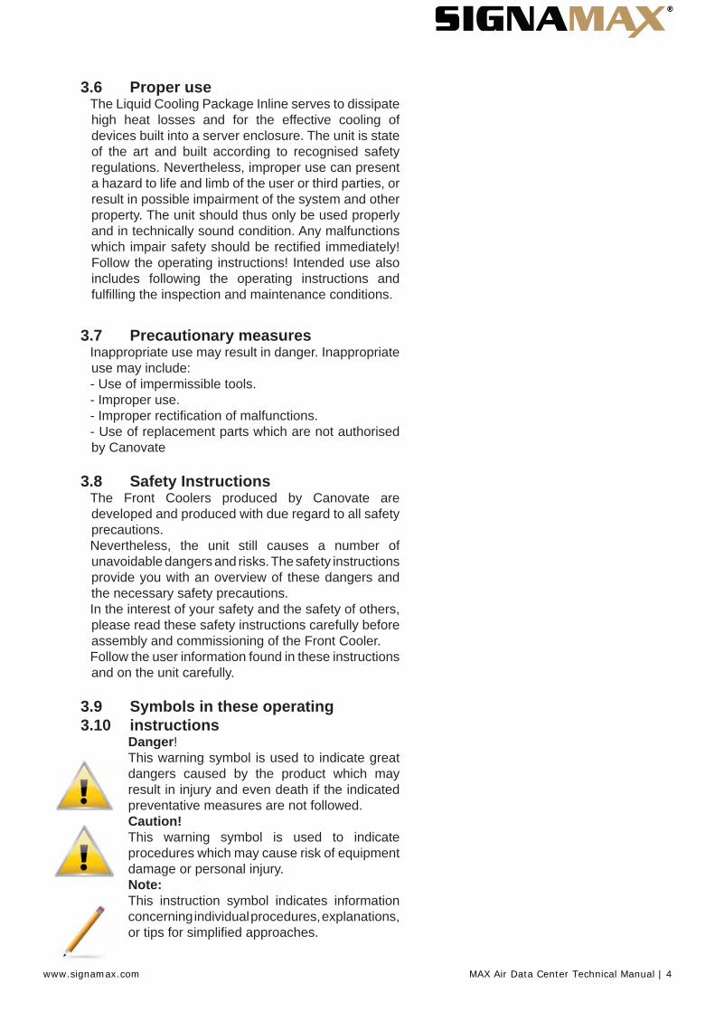
3.6 Proper useThe Liquid Cooling Package Inline serves to dissipate high heat losses and for the effective cooling of devices built into a server enclosure. The unit is state of the art and built according to recognised safety regulations. Nevertheless, improper use can present a hazard to life and limb of the user or third parties, or result in possible impairment of the system and other property. The unit should thus only be used properly and in technically sound condition. Any malfunctions which impair safety should be rectifi ed immediately! Follow the operating instructions! Intended use also includes following the operating instructions and fulfi lling the inspection and maintenance conditions.
3.7 Precautionary measuresInappropriate use may result in danger. Inappropriate use may include:- Use of impermissible tools.- Improper use.- Improper rectifi cation of malfunctions.- Use of replacement parts which are not authorisedby Canovate
3.8 Safety InstructionsThe Front Coolers produced by Canovate are developed and produced with due regard to all safety precautions.Nevertheless, the unit still causes a number of unavoidable dangers and risks. The safety instructions provide you with an overview of these dangers and the necessary safety precautions.In the interest of your safety and the safety of others, please read these safety instructions carefully before assembly and commissioning of the Front Cooler.Follow the user information found in these instructions and on the unit carefully.
3.9 Symbols in these operating 3.10 instructions
Danger!This warning symbol is used to indicate great dangers caused by the product which may result in injury and even death if the indicated preventative measures are not followed.Caution!This warning symbol is used to indicate procedures which may cause risk of equipment damage or personal injury.Note:This instruction symbol indicates information concerning individual procedures, explanations, or tips for simplifi ed approaches.
www.signamax.com MAX Air Data Center Technical Manual | 4
3.11 Important safety instructions
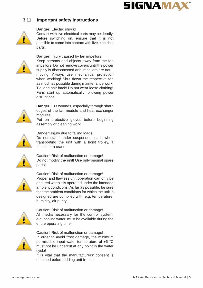
Danger! Electric shock!Contact with live electrical parts may be deadly.Before switching on, ensure that it is not possible to come into contact with live electrical parts.
Danger! Injury caused by fan impellors!Keep persons and objects away from the fan impellors! Do not remove covers until the power supply is disconnected and impellors are notmoving! Always use mechanical protection when working! Shut down the respective fan as much as possible during maintenance work! Tie long hair back! Do not wear loose clothing!Fans start up automatically following power disruptions!
Danger! Cut wounds, especially through sharp edges of the fan module and heat exchanger modules!Put on protective gloves before beginning assembly or cleaning work!
Danger! Injury due to falling loads!Do not stand under suspended loads when transporting the unit with a hoist trolley, a forklift, or a crane.
Caution! Risk of malfunction or damage!Do not modify the unit! Use only original spare parts!
Caution! Risk of malfunction or damage!Proper and fl awless unit operation can only be ensured when it is operated under the intended ambient conditions. As far as possible, be sure that the ambient conditions for which the unit is designed are complied with, e.g. temperature, humidity, air purity.
Caution! Risk of malfunction or damage!All media necessary for the control system, e.g. cooling water, must be available during theentire operating time.
Caution! Risk of malfunction or damage!In order to avoid frost damage, the minimum permissible input water temperature of +6 °C must not be undercut at any point in the water cycle!It is vital that the manufacturers’ consent is obtained before adding anti-freeze!
www.signamax.com MAX Air Data Center Technical Manual | 5
Caution! Risk of malfunction or damage!During storage and transportation below freezing point, the water cycle should be drained completely using compressed air!
Caution! Risk of malfunction or damage!Only set the temperature control setpoint as low as is strictly necessary, since the danger of condensation through undercutting the dew point increases with a falling water inlet temperature!Ensure that the enclosure is sealed on all sides, particularly at the cableentry (condensation)!
3.12 Service and technical staffThe installation, commissioning, maintenance and repair of this unit may only be carried out by qualifi ed mechanical and electro-technical trained personnel.Only properly instructed personnel may carry out service on a unit while in operation.
3.13 RoHS complianceFront Cooler fulfi ls the requirements of EU directive 2002/ 95/EC on the Restriction of Use of Certain Hazardous Substances in Electrical and Electronic Equipment (RoHS) of 13 February, 2014.Note:Corresponding information concerning the RoHS directive is provided by our fi rm on the Internet at www.canovate.com
www.signamax.com MAX Air Data Center Technical Manual | 6
4. Transport and handling4.1 Scope of delivery of Front Cooler
The scope of delivery of a Front Cooler includes:
Qty. Parts
Front Cooler, ready for connection
11111114
Accessories:Pipe fi tting condensate pumpCondensate hose for condensate pumpCondensate hose emergency overfl owSealing stripConnection plugCable tie and spreading anchorJumper for connection plug (strain relief for connection cable)Eyebolts
1 Assembly instructions
4.2 TransportThe Front Cooler is delivered shrink-wrapped on a pallet.
Caution!Because of its height and small base, the Front Cooler
is subject to tipping. Risk of toppling, especially after the unit is removed from the pallet!
Caution!Transport of the Front Cooler without a pallet:- Use only suitable and technically sound liftinggear and load-bearing devices with suffi cientload capacity.
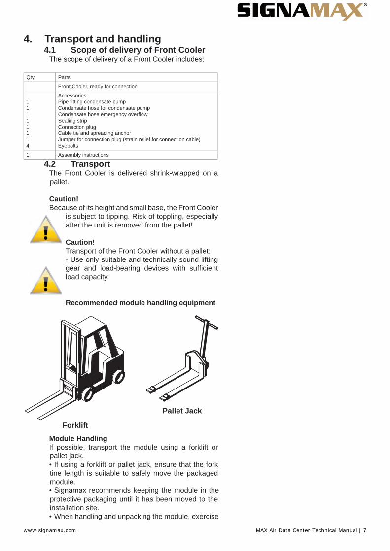
Recommended module handling equipment
Forklift
Pallet Jack
Module HandlingIf possible, transport the module using a forklift or pallet jack.• If using a forklift or pallet jack, ensure that the forktine length is suitable to safely move the packagedmodule.• Signamax recommends keeping the module in theprotective packaging until it has been moved to theinstallation site.• When handling and unpacking the module, exercise
www.signamax.com MAX Air Data Center Technical Manual | 7

great care to prevent damage.• Do not lift the module any higher than 6” (152mm)while moving it. If it must be lifted higher than6” (152mm), exercise great care and keep allpersonnel who are not helping move the moduleat least 20’ (5m) away from the module.• The Front Cooler ships with four outrigger-stylewheels to permit rolling it into position. Signamaxrecommends using a forklift or pallet jack to move theFront Cooler as near as practical to its installation sitebefore removing it from the shipping pallet.
4.3 UnpackingUpon arrival of the module and before unpacking, verify that the labeled equipment matches the bill of lading. Carefully inspect all items for either visible or concealed damage. Damage should be immediately reported to the carrier and a damage claim filed with a copy sent to your Signamax sales representative. If you later find any concealed damage, report it to both the shipping company and your chosen disrtibrutuon outlet.
Check to be sure all required assemblies and parts have been received.
The Front Cooler is shipped in protective packaging and secured to a pallet (see Figure 5). Do not remove these protective items from the Front Cooler before it is at the installation location. When unpacking and handling the Front Cooler, exercise extra care to prevent damage.
CautionRisk of sudden refrigerant discharge. Can cause loss of charge and minor injury.If the optional pre-charged option is chosen, the Front Cooler module is shipped with a full charge of R-134a refrigerant under pressure. Do not removethe pipe caps or plugs before the module is ready forconnection to Front Cooler Piping.
Supply and return fi ttings on the pre-charg ed Front Cooler modules are one-shot couplings.Do not disconnect one-shot couplings after they have been connected. Disconnection will release pressurized R-134a refrigerant from the Front Cooler.
Recyclable PackagingAll material used to package this module is recyclable. Please save for future use or dispose of the material appropriately.
WARNING : Risk of top-heavy module falling over. Can cause equipment damage, injury and death. Read all of the following instructions before attempting to move, lift, remove packaging from the module, or
www.signamax.com MAX Air Data Center Technical Manual | 8

preparing module for installation.Use extreme caution and care when moving and installing this unit. Use lifting equipment that is rated for the weight of the unit by an OSHA-certifi ed rating organization. Personnel should be properly trained and qualifi ed to move and rig equipment
CAUTION: Risk of sharp edges, splinters and exposed fasteners. Can cause personal injury.Only properly trained personnel wearing appropriate safety headgear, gloves, shoes and glasses should attempt to move, lift, remove packaging from, or prepare module for installation
NOTICE :Risk of overhead interference. Can cause module or structure damage.The module may be too tall to fi t through a doorway while on the skid. Measure the module and doorway heights and refer to the installation plans before moving the module to verify clearances.
NOTICE: Risk of improper storage. Can cause module damage.Keep the module indoors and protected from dampness, freezing temperatures and contactdamage.
NOTICE :Risk of damage from forklift. Improper handling with the forklift can cause exterior and/or underside damage.Keep tines of the forklift level and at a height suitable to fi t below the pallet.
Domestic Packaging1. Remove the exterior stretch-wrap packaging fromaround the module, exposing the protective cornerand side packaging planks.2. Remove corner and side packaging planks fromthe module, exposing the bag over the module.Remove the bag when ready to install the FrontCooler.
Planks at the corners and on the sides protect the Front Cooler during shipping
Remove the Stabilizers at the corners
Exterior stretch wrapping surrounds other protective shipping features
www.signamax.com MAX Air Data Center Technical Manual | 9
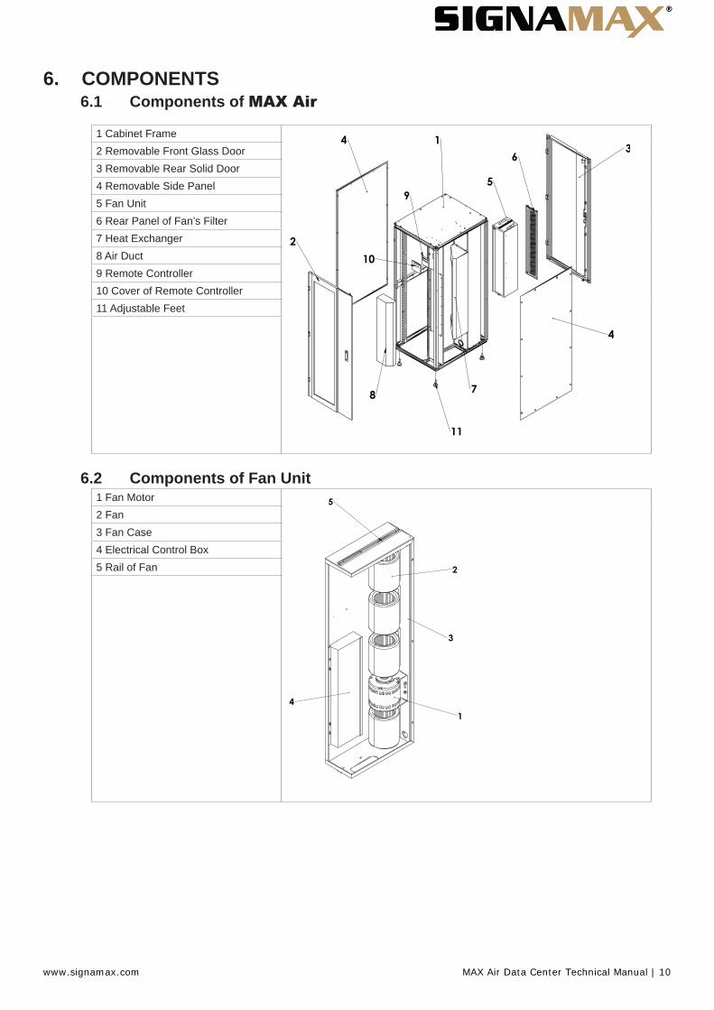
6. COMPONENTS6.1 Components of MAX Air
1 Cabinet Frame2 Removable Front Glass Door3 Removable Rear Solid Door4 Removable Side Panel5 Fan Unit6 Rear Panel of Fan’s Filter7 Heat Exchanger8 Air Duct9 Remote Controller10 Cover of Remote Controller11 Adjustable Feet
6.2 Components of Fan Unit1 Fan Motor2 Fan3 Fan Case4 Electrical Control Box5 Rail of Fan
www.signamax.com MAX Air Data Center Technical Manual | 10
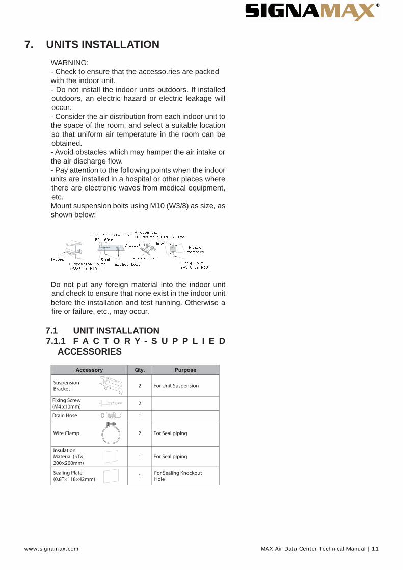
7. UNITS INSTALLATIONWARNING:- Check to ensure that the accesso.ries are packedwith the indoor unit.- Do not install the indoor units outdoors. If installedoutdoors, an electric hazard or electric leakage willoccur.- Consider the air distribution from each indoor unit tothe space of the room, and select a suitable locationso that uniform air temperature in the room can beobtained.- Avoid obstacles which may hamper the air intake orthe air discharge fl ow.- Pay attention to the following points when the indoorunits are installed in a hospital or other places wherethere are electronic waves from medical equipment,etc.Mount suspension bolts using M10 (W3/8) as size, asshown below:
�
�
�
�������������
�� � ������������������������������ �
� �� ��������������������������������
���� ��!��������"��#�$����� �
��!�����
%�!�������������&'�����
��(�������������������������
)���
Do not put any foreign material into the indoor unit and check to ensure that none exist in the indoor unitbefore the installation and test running. Otherwise a fi re or failure, etc., may occur.
7.1 UNIT INSTALLATION7.1.1 F A C T O R Y - S U P P L I E D
ACCESSORIES
www.signamax.com MAX Air Data Center Technical Manual | 11

7.1.2 INITIAL CHECKIndoor unit with proper clearance around it for operation and maintenance working space, as shown below
(mm)
Min. 40
Min.400
Min
.50
0 Min. 8
Min. 300Min. 300
Check down slope pitch of drain piping is following the specifi cation indicate in chapter ‘Drain Piping’
8. DRAIN PIPING8.1 GENERAL
CAUTION:- Do not create an upper-slope or rise for the drainpiping, since drain water will fl ow back to the unitandleakage to the room will occur when the unitoperation is stopped.Incorrect: Upward Slope
Incorrect: Risin g Part
INCORRECT
Do not connect the drain pipe with sanitary or sewagepiping or any other drainage piping.- When the common drain piping is connectedwith other indoor units, the connected position ofeach indoor unit must be higher than the commonpiping.The pipe size of the common drain pipe mustbe large enough according to the unit size andnumber of unit.
Common Drain Piping
1/25~1/100 Down Slope Drain Piping connection
CORRECT
Drain piping will require insulating if the drain is installed in a location where condensation forming onthe outside of drain pipe may drop and cause damage. The insulation for the drain pipe must be selected to insure vapor sealing and prevent condensation forming.
www.signamax.com MAX Air Data Center Technical Manual | 12
Drain trap should be installed next to indoor unit. Thistrap must be designed to good practice and be checked with water (charged) and tested for correct fl ow. Do not tie or clamp the drain pipe and refrigerant pipe together.
NOTE:Install drainage in accordance with national and localcodes.
After performing drain piping work and electrical wiring, check to ensure that water fl ows smoothly as in the following procedure:
Checking Unit without Drain-up Mechanism- Pour approximately 1.8 liters of water into the drainpan.- Check to ensure that the water fl ows smoothly orwhether no water leakage occurs. When water cannotbe found at the end of the drain piping, pour anotherapproximately 1.8 liters of water into the drain pan.
NOTE:Pay attention to the thickness of the insulation when the left side piping is performed. If it is too thick, piping can not be installed in the unit.
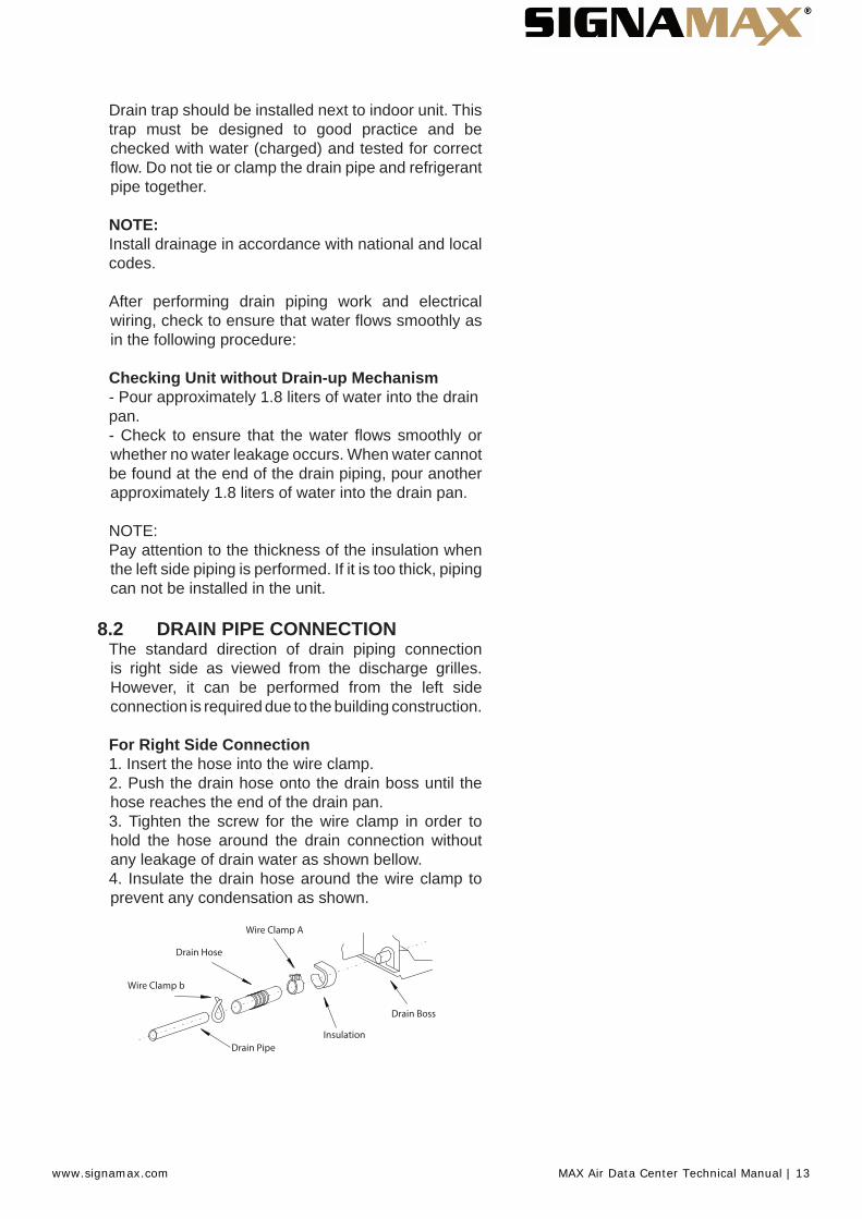
8.2 DRAIN PIPE CONNECTIONThe standard direction of drain piping connection is right side as viewed from the discharge grilles. However, it can be performed from the left side connection is required due to the building construction.
For Right Side Connection1. Insert the hose into the wire clamp.2. Push the drain hose onto the drain boss until thehose reaches the end of the drain pan.3. Tighten the screw for the wire clamp in order tohold the hose around the drain connection withoutany leakage of drain water as shown bellow.4. Insulate the drain hose around the wire clamp toprevent any condensation as shown.
Wire Clamp A
Drain Hose
Drain PipeInsulation
Drain Boss
Wire Clamp b
www.signamax.com MAX Air Data Center Technical Manual | 13

For Left Side Connection
Drain Boss
Drain Plug Rear Side
Fastener Band
Drain Plug
Insulation Plug
Fan Runner Fan Motor
Remove the drain plug of the left-side drain boss asindicated in the following procedure.1. Cut the fastener.2. Remove the insulation material.3. Remove the drain plug.4. Insert the drain plug into the right-side and drainboss using a driver as shown below.
Driver Drain Plug Drain Connection
Unit Side
5. After inserting the drain plug into the right-side drainboss, seal the jointed part by using a water-proofchloride type sealing material and secure it with afastener.
Seal Material
Plug
6. Wrap the insulation material around the drainconnection.7. Connect the drain hose to the left side drainconnection using the same procedure as for the rightside drain connection.
Connecting a Drain Piping1. Prepare a polyvinyl chloride (PVC) tube with anouter diameter of 26mm. (VP20)2. Pay attention to the position of the drain pipe. Keepthe down-slope, 1/25 to 1/100. Do not create an upperslope or rise for the drain piping.3. Seal the connecting part of the drain pipe by usingthe water-proof chloride type sealing material.4. Wrap the insulation material around the connectingpart perfectly.5. Fasten the drain pipe to the connecting part usingthe factory-supplied clamp.
www.signamax.com MAX Air Data Center Technical Manual | 14

Drain HoseInsulation (field su pplied)
Secure Downward Slope
ClampInsulation
6. Do not connect the drain pipe with sanitary sewageor any other drainage pipe.7. When installing the pipe, do not tie the drain pipeand refrigerant pipe together. Tie the drain pipe asshown below
Band Band
Rear Side piping Rear Side piping
8. After completing the drain pipe work, pour waterinto the drain pan and check to ensure that waterfl ows smoothly
9. ELECTRICAL WIRING9.1 ELECTRICAL WIRING CONNECTIONFOR INDOOR UNIT
CAUTION:Use twisted shielded pair cable or shield pair cablefor transmission wires between the indoor and theoutdoor units, and connect the shielded part to theearth screw in the electrical box of the indoor unit asshown below.Single phase connection
Remote Control (PC-ART)
Transmission Wires
Power supply wires (Single phase)
Earth Screw
www.signamax.com MAX Air Data Center Technical Manual | 15

The electrical wiring connection for the indoor unit is shown below.1. Connect the cable of the remote control switch tothe terminals A and B in electrical box through theconnecting hole in the cabinet, as shown below.2. Connect the power supply and ground wires to theterminals in the electrical box.3. Connect the wires between the indoor unit and theoutdoor unit to the terminals 1 and 2 in the electricalbox, as shown below:
Cord clamp
RCS (Optional)
Electrical Box
Grille
Knockout hole for wirings
Transmission wires
Power wires
RCS (Optional) Connector
9.2 SETTINGS OF DIP SWITCHESQuantity and Position of Dip SwitchesDips switches position is the following:
DSW6
DSW5DSW4
DSW3
DSW7
RSW1
RSW2
CAUTION:Before setting dips switches, fi rstly turn off power source and set the position of the dips switches. If theswitches are set without turning off the power source,the contents of the setting are invalid.
DSW3: Capacity Code SettingNo setting is required, due to setting before shipment. This dip switch is utilized for setting the capacity code which corresponds to the Horse Power of the indoor unit.
HP 1.8 2.0 2.3 2.5
Setting Position
ON
1 2 3 4
ON
1 2 3 4
ON
1 2 3 4
ON
1 2 3 4
3.0 4.0 5.0 6.0
Setting Position
ON
1 2 3 4
ON
1 2 3 4
ON
1 2 3 4
ON
1 2 3 4
www.signamax.com MAX Air Data Center Technical Manual | 16

DSW6 and RSW1: Unit No. SettingThe below fi gure indicates the position before shipment.
DSW6 RSW1
ON
1 2 3 4 5 6
Here is set DSW6 and RSW1 before shipment up to 63 can be set.
Ex. Setting nº16 RSW1
ON
1 2 3 4 5 6
Indication Use flathead driver
Nº 1 PIN is on Fix to 6
DSW5 and RSW2: Refrigerant Cycle No. SettingSetting is required. Setting position before shipment in
DSW5 RSW2
ON
1 2 3 4 5 6
Here is set DSW5 and RSW2 before shipment up to 63 can be set.
Ex. Setting 5 system RSW2
ON
1 2 3 4 5 6All pins are OFF
Fix to 5
DSW4: Unit Model Code SettingNo setting is required. This switch is utilized for setting the model code which corresponds to the indoor unit type.
Indoor Unit Model DSW4 Setting
RPC ON
1 2 3 4
www.signamax.com MAX Air Data Center Technical Manual | 17
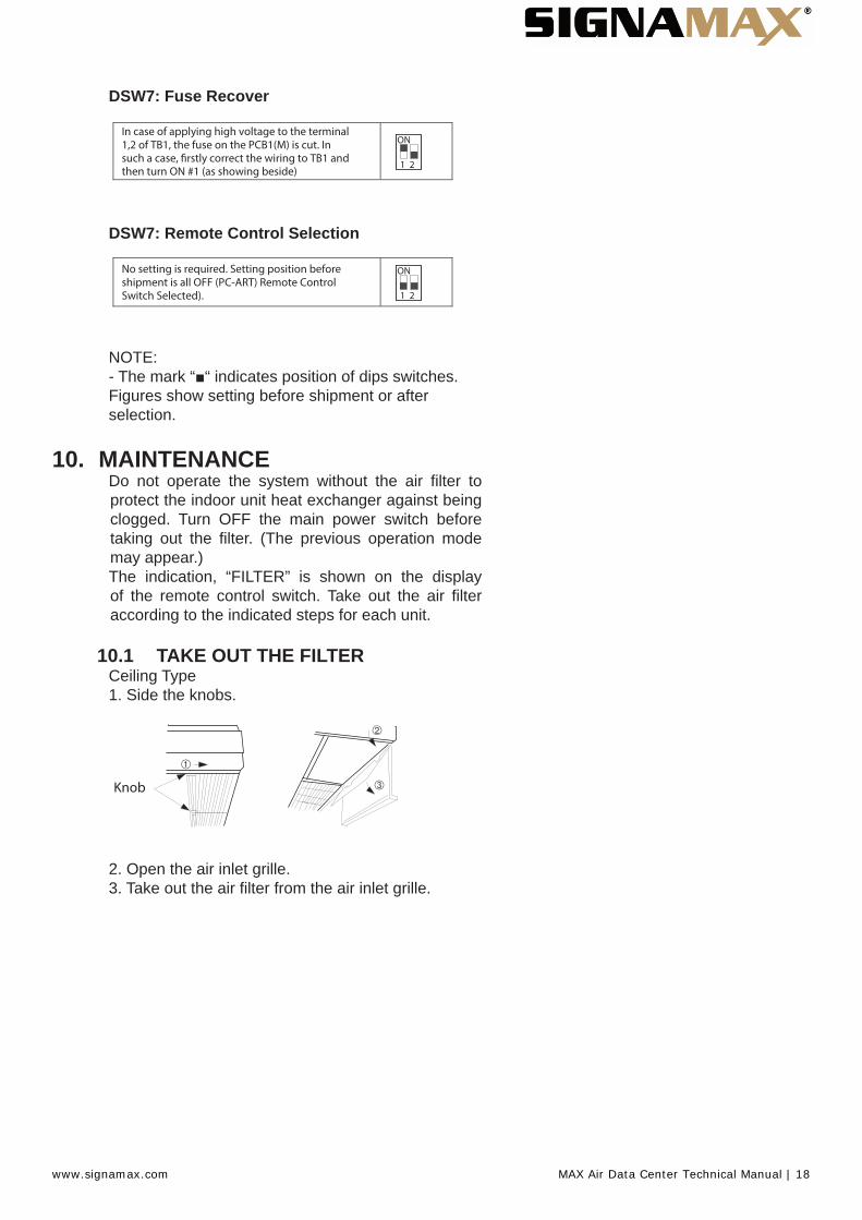
DSW7: Fuse Recover
In case of applying high voltage to the terminal 1,2 of TB1, the fuse on the PCB1(M) is cut. In such a case, firstly correct the wiring to TB1 and then turn ON #1 (as showing beside)
ON
1 2
DSW7: Remote Control Selection
No setting is required. Setting position before shipment is all OFF (PC-ART) Remote Control Switch Selected).
ON
1 2
NOTE:- The mark “■“ indicates position of dips switches.Figures show setting before shipment or afterselection.
10. MAINTENANCEDo not operate the system without the air fi lter toprotect the indoor unit heat exchanger against being clogged. Turn OFF the main power switch before taking out the fi lter. (The previous operation mode may appear.)The indication, “FILTER” is shown on the display of the remote control switch. Take out the air fi lter according to the indicated steps for each unit.
10.1 TAKE OUT THE FILTERCeiling Type1. Side the knobs.
Knob
2. Open the air inlet grille.3. Take out the air fi lter from the air inlet grille.
www.signamax.com MAX Air Data Center Technical Manual | 18

10.2 CLEAN THE FILTER
Clean the air fi lter according to the following steps:1. Use a vacuum cleaner or let water fl ow onto the airfi lter for removing the dirt from the air fi lter.
CAUTION:Do not use hot water higher than approximately 40ªC2. Dry the air fi lter in the shade after shaking offmoisture.3. Do not use cleaner or other chemicals
10.3 RESET OF FILTER INDICATIONAfter cleaning the air fi lter, press the “RESET” button. The FILTER indication will disappear and the next fi lter cleaning time is set.
www.signamax.com MAX Air Data Center Technical Manual | 19

11. OUTDOOR UNIT11.1 Important Notice
• No part of this manual may be reproduced withoutwritten permission.• If you have any questions, contact yourauthorized service contractor of Signamax products.• This manual gives a common description andinformation for this air conditioner which you operateas well as for other models.• Check and make sure that the explanations of eachpart of this manual correspond to your air conditionermodel.• Refer to the models codifi cation to con fi rm the main characteristics of your system.• Signal words (DANGER, WARNING andCAUTION) are used to identify levels of hazardseriousness. Defi nitions for identifying hazard levels are provided below with their respective signalwords.• It is assumed that this unit will be operated andserviced by English speaking people. If this is not thecase, the customer should add safety, caution andoperating signs in the native language of the personal.• This air conditioner has been designed for thefollowing temperature. Operate the air conditionerwithin this range:
TemperatureMaximum Minimum
Cooling Mode
Indoor 32°C DB/23°C WB 21°C DB/15°C WB
Outdoor 46 ºC DB -5 °C DB
Heating Mode
Indoor 27 °C DB 15 °C DB
Outdoor 15 °C WB -20 °C WB
DB: Dry Bulb Temperature WB: Wet Bulb Temperature
These operations modes are controlled by the remote control switch.• This manual should be considered as a permanentpart of the air conditioner. This manual gives acommon description and information for this airconditioner which you operate as well as for othermodels.
DANGERPressure Vessel and Safety Device: This air conditioner is equipped with a high pressure vessel under PED (Pressure Equipment Directive). The pressure vessel has been designed and tested before shipment according to PED. Also, in order to prevent the system from an abnormal pressure, a high pressure switch, which needs no fi eld adjustment, is
www.signamax.com MAX Air Data Center Technical Manual | 20
utilized in the refrigeration system.Therefore, this air conditioner is protected from abnormal pressures. However, if abnormally high pressure is applied to the refrigeration cycle including the high pressure vessel(s), it will result in serious injury or death due to explosion of the pressure vessel.Do not apply a pressure higher than the following pressure to the system, by modifying or changing the high pressure switch.
CAUTIONThis unit is designed for commercial and light industrial application.If installed in house hold appliance, it could cause electromagnetic interference.
Start-up and Operation: Check to ensure that all the stop valves are fully opened and no obstacle exists at the inlet/outlet sides before start-up and during the operation.
Maintenance: Periodically check the high pressure side pressure.If the pressure is higher than the maximum allowable pressure, stop the system and clean the heat exchanger or remove the cause.
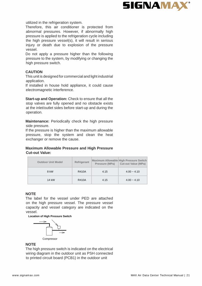
Maximum Allowable Pressure and High Pressure Cut-out Value:
Outdoor Unit Model Refrigerant Maximum Allowable Pressure (MPa)
High Pressure Switch Cut-out Value (MPa)
8 kW R410A 4.15 4.00 ~ 4.10
14 kW R410A 4.15 4.00 ~ 4.10
NOTEThe label for the vessel under PED are attached on the high pressure vessel. The pressure vessel capacity and vessel category are indicated on the vessel.
Location of High Pressure Switch
Compressor
NOTEThe high pressure switch is indicated on the electrical wiring diagram in the outdoor unit as PSH connected to printed circuit board (PCB1) in the outdoor unit
www.signamax.com MAX Air Data Center Technical Manual | 21
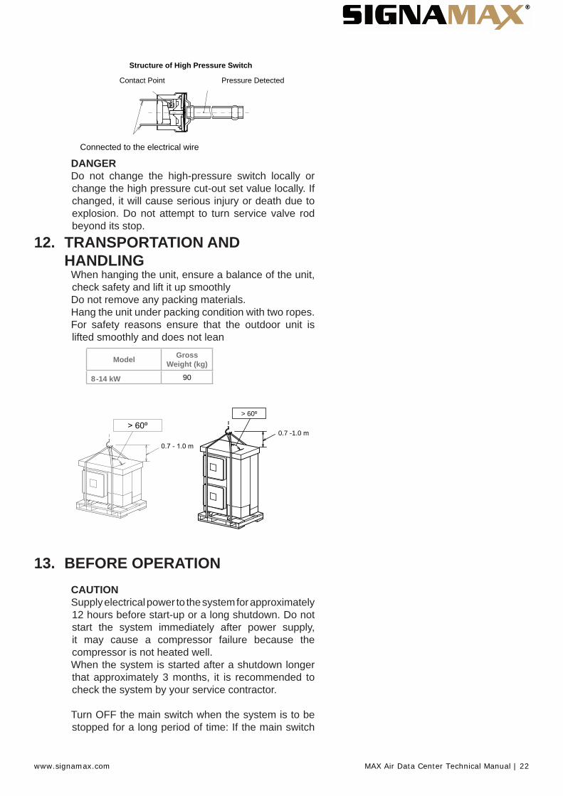
Structure of High Pressure Switch
Contact Point Pressure Detected
Connected to the electrical wire
DANGERDo not change the high-pressure switch locally or change the high pressure cut-out set value locally. If changed, it will cause serious injury or death due to explosion. Do not attempt to turn service valve rod beyond its stop.
12. TRANSPORTATION ANDHANDLING
When hanging the unit, ensure a balance of the unit, check safety and lift it up smoothlyDo not remove any packing materials.Hang the unit under packing condition with two ropes.For safety reasons ensure that the outdoor unit is lifted smoothly and does not lean
Gross Weight (kg)Model
8-14 kW 90
0.7 -1.0 m
> 60º
13. BEFORE OPERATIONCAUTIONSupply electrical power to the system for approximately 12 hours before start-up or a long shutdown. Do not start the system immediately after power supply, it may cause a compressor failure because the compressor is not heated well.When the system is started after a shutdown longer that approximately 3 months, it is recommended to check the system by your service contractor.
Turn OFF the main switch when the system is to be stopped for a long period of time: If the main switch
www.signamax.com MAX Air Data Center Technical Manual | 22

is not turned OFF, electricity will be used, because the oil heater is always energised during compressor stopping.Make sure that the outdoor unit is not covered with snow or ice.If covered, remove it by using hot water (approximately 50°C). If the water temperature is higher that 50 °C, it will cause damage to plastic parts.
14. AUTOMATIC CONTROLSThe system is equipped with the following functions.Three minute guardThe compressor remains off for at least 3 minutes once it has stopped. If the system is started within approximately 3 minutes after it has stopped, the RUN indicator is activated. However, the cooling operation or the heating operation remains off and does not start until after 3 minutes has elapsed.Operation may stop for 6 minutes maximum to protect compressor.Frost prevention during cooling operationWhen the system is operated in a low temperature room, the cooling operation may be changed to fan operation for a while to avoid frost formation on the indoor heat exchanger.Automatic restart after power failureIf the power supply is interrupted for short periods of time (up to 2 seconds) the Remote Control switch will retain the settings and the unit will restart when the power is restored. If Automatic Restart is required after periods of lost power supply in excess of 2 seconds please contact your distributor (optional function).
Slow air control during heating operationCan be setting than when the compressor is stopped while the thermostat is OFF, or the system is performing the automatic defrosting operation, the fan speed is set at the slow position.Automatic defrosting cycleWhen the heating operation is stopped by pressing RUN/STOP switch, frosting on the outdoor unit is checked and the defrosting operation may be performed for the maximum of 10 minutes.Prevention of overload operationWhen the outdoor temperature is too high during heating operation, heating operation is stopped due to activation of the outdoor thermistor until the temperature becomes low.Hot start during heating operationTo prevent cold air discharge, the fan speed is controlled from the slow position to the set position according to the discharge air temperature. At this time the lover is fi xed horizontally.
www.signamax.com MAX Air Data Center Technical Manual | 23

15. BASIC TROUBLESHOOTINGCAUTIONWhen water leakage from the indoor unit occurs, stop the operation and contact your contractorWhen you smell or white smoke occurs from the unit, stop the system and contact your contractor.This is not abnormal• Sound from deforming PartDuring system starting or stopping, and abradingsound might be heard. However, this is due to thermaldeformation of plastic parts. It is not abnormal.• Refrigerant Flow SoundWhile the system is being started or stopping, soundfrom the refrigerant fl ow may be heard.• Smells from Indoor UnitSmell adheres on indoor unit after a long period oftime. Clean the air fi lter and panels or make a goodventilation.• Steam from Outdoor Heat ExchangerDuring defrosting operation, ice on the outdoor heatexchanger is melted, resulting in making steam.• Dew on Air PanelWhen the cooling operation continues for a longperiod of time under high humidity conditions (higherthan 27°C DB/80% R.H.), dew can form on the airpanel.• Dew on CabinetWhen the cooling operation continues for a longperiod of timer (higher than 27°C DB/80% R.H.), dewcan form on the cabinet.
• Sound for the indoor unit heat exchangerDuring the cooling operation, a sound may be heardfrom the indoor unit heat exchanger due to waterfreezing or melting.
No operationCheck whether the SET TEMPERATURE is set at the correct temperature.Not cooling well or heating well-- Check for obstruction of air fl ow of the outside or inside units.-- Check if too much heat source exists in the room.-- Check if the air fi lter is clogged with dust.-- Check to see if the doors or windows are opened or not.-- Check if the temperature condition is not within the operating range.Abnormal swing louver’s positionCheck if the four louver’s position at the air outlet are in same
www.signamax.com MAX Air Data Center Technical Manual | 24
position.If trouble still remains...If the trouble still remains even after checking the above items, contact your service contractor and inform the following data:-- Unit Model Name-- Content of Trouble-- Alarm Code no. on Liquid Crystal Display
NOTEExcept for a long period of shutdown, keep the main switch ON, since the oil heater is energised when the compressor is stopped.
www.signamax.com MAX Air Data Center Technical Manual | 25

16. NAME OF PARTS OUTDOOR UNITNo. Part Name
1 Compressor
2 Accumulator
3 Heat exchanger
4 Propeller fan
5 Fan motor
6 Strainer
7 Distributor
8 Reversing valve
9 Micro-computer control expansion valve
10 Solenoid valve for hot gas
11 Stop valve for gas line
12 Stop valve for liquid line
13 Check Joint
14 Electrical box
15 High pressure switch for protection
17 Pressure switch for control
18 Silencer
19 Crankcase heater
20 Vibration absorbing rubber (3pcs.)
21 Air outlet
22 Air inlet
www.signamax.com MAX Air Data Center Technical Manual | 26

A
B
CDF
F
E
Mark Part nameA Gas line refrigerant piping connectionB Liquid line refrigerant piping connectionC Outdoor unitD Ambient thermistorE Discharge gas thermistorF Pipe thermistor
No Part name1 Compressor2 Heat exchanger3 Accumulator4 Micro-Computer control expansion valve5 Reversing valve6 Solenoid valve for gas bypass7 Strainer8 Distributor9 Check joint10 High pressure switch for protection11 Pressure switch for control12 Stop valve for gas line13 Stop valve for liquid line14 Silencer
R410A 4.15 MPa
or cooling for heatingConnection by Connection by
welding Gas refrigerant Leakage test pressure
www.signamax.com MAX Air Data Center Technical Manual | 27

17. UNIT INSTALLATION17.1 OUTDOOR UNIT INSTALLATION
CAUTIONTransport the products as close to the installation location as practical before unpacking.Do not put any material on the products.Apply four lifting wires on to the outdoor, when lifting it by craneCAUTION• Install the outdoor unit with suffi cient clearancearound it for operation and maintenance as shown inthe next fi gures. Install the outdoor unit where goodventilation is available• Do not install the outdoor unit where is a highlevel of oil mist, salty air or sulphurous atmosphere.• Install the outdoor unit as far as practical (beingat least 3 meters) from electromagnetic wave radiator(such as medical equipment).• For cleaning, use noninfl ammable andnontoxic cleaning liq- uid. Use of infl ammable agentmay cause explosion or fi re.• Work with suffi cient ventilation, for working inan enclosed space may cause oxygen defi ciency.Toxic gas may be pro- duced when cleaning agent isheated to high temperature by, e.g., being exposed tofi re.• Cleaning liquid shall be collected after cleaning.• Pay attention not to clamp cables whenattaching the service cover to avoid electric shock orfi re.C A U T I O NKeep clearance between the units of more than100mm, and avoid obstacles that may hamper airintake, when installing more than one units together.Install the outdoor unit in the shade or not exposedto direct sun- shine or direct radiation from hightemperature heat source.Do not install the Outdoor Unit in a space where aseasonal wind directly blows to the Outdoor fan.Check to ensure that the foundation is fl at, level andsuffi ciently strong.Install the unit in a restricted area not accessible bythe general public Aluminium fi ns have very sharpedges. Pay attention to the fi ns to avoid injury
www.signamax.com MAX Air Data Center Technical Manual | 28
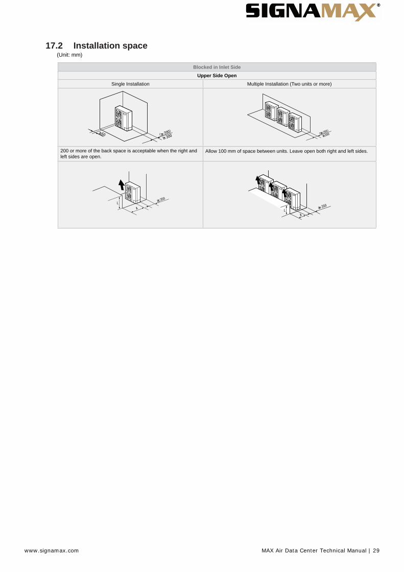
17.2 Installation space(Unit: mm)
Blocked in Inlet SideUpper Side Open
Single Installation Multiple Installation (Two units or more)
200 or more of the back space is acceptable when the right and left sides are open.
Allow 100 mm of space between units. Leave open both right and left sides.
www.signamax.com MAX Air Data Center Technical Manual | 29
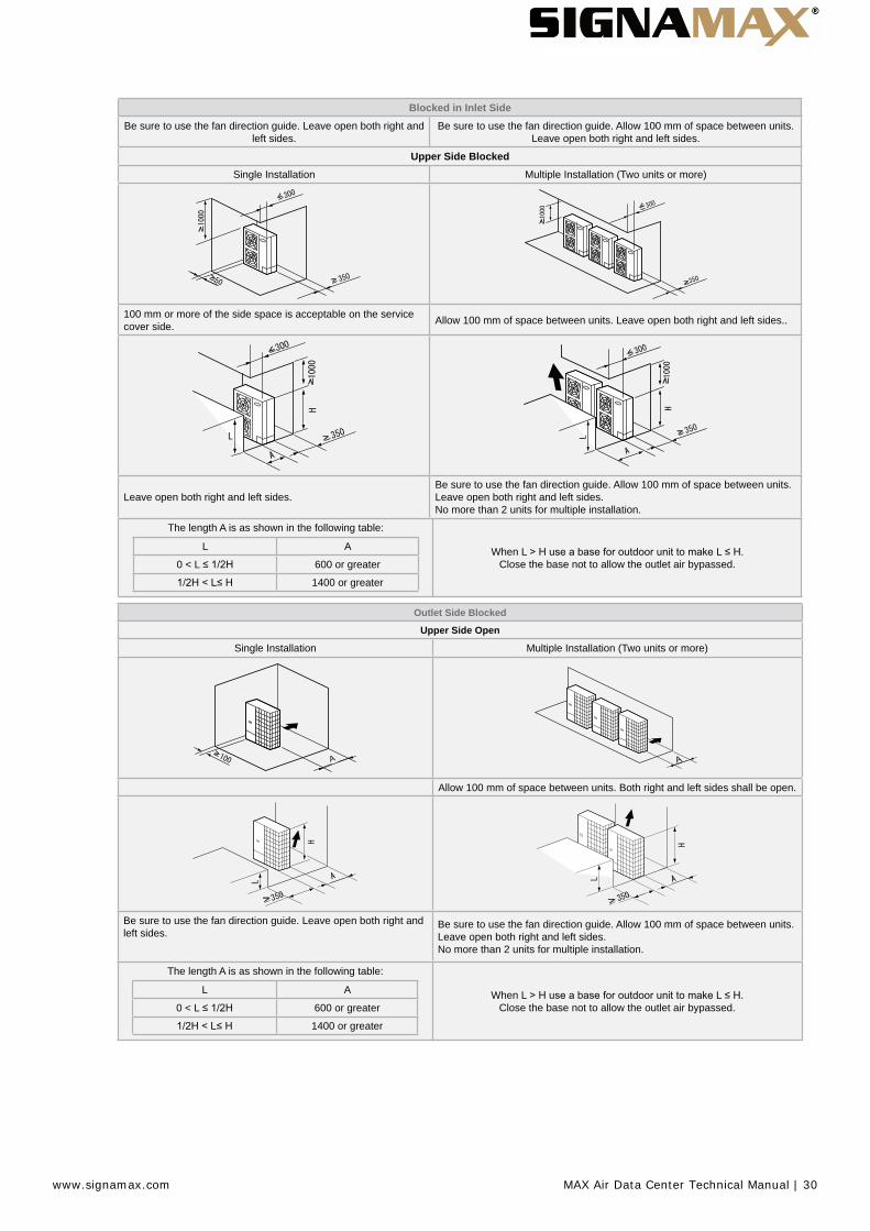
Blocked in Inlet SideBe sure to use the fan direction guide. Leave open both right and
left sides.Be sure to use the fan direction guide. Allow 100 mm of space between units.
Leave open both right and left sides.
Upper Side BlockedSingle Installation Multiple Installation (Two units or more)
100 mm or more of the side space is acceptable on the service cover side. Allow 100 mm of space between units. Leave open both right and left sides..
Leave open both right and left sides.Be sure to use the fan direction guide. Allow 100 mm of space between units. Leave open both right and left sides. No more than 2 units for multiple installation.
The length A is as shown in the following table:
L A
0 < L 600 or greater
1400 or greater
When L L Close the base not to allow the outlet air bypassed.
Outlet Side Blocked
Upper Side Open
Single Installation Multiple Installation (Two units or more)
Allow 100 mm of space between units. Both right and left sides shall be open.
Be sure to use the fan direction guide. Leave open both right and left sides.
Be sure to use the fan direction guide. Allow 100 mm of space between units. Leave open both right and left sides. No more than 2 units for multiple installation.
The length A is as shown in the following table:
L A
0 < L 600 or greater
1400 or greater
When L L Close the base not to allow the outlet air bypassed.
www.signamax.com MAX Air Data Center Technical Manual | 30

17.3 Installation place provisionConcrete Foundation1 Foundation could be on fl at and is recommended be 100-300 mm higher than ground level.2 Install a drainage around foundation for smooth drain3 When installing the outdoor unit fi x the unit by anchor bolts of M10.4 When installing the unit on a roof or a veranda, drain water sometimes turns to ice on a cold morning. Therefore, avoid draining in an area that people often use because it is slippery.
* Space for downward piping space
Nº Description1 Outdoor Unit
2
3 Mortar Hole (Ø100xDepth 150)
4 Anchor Bolt M10 (Ø12.5 Hole)
5 Drainage (Wide 100xDepth 150)
6 Drainage
7 Vibration-proof rubber
N O T EWhen the mark * dimension is secured, piping work from bottom side is easy without interference of foundation.
5 The whole of the base of the outdoor unit should be installed on a foundation. When using vibration-proof mat, it should also be positioned the same way. When installing the outdoor unit on a fi eld supplied frame, use metal plates to adjust the frame width for stable installation as shown in below fi gure.
www.signamax.com MAX Air Data Center Technical Manual | 31
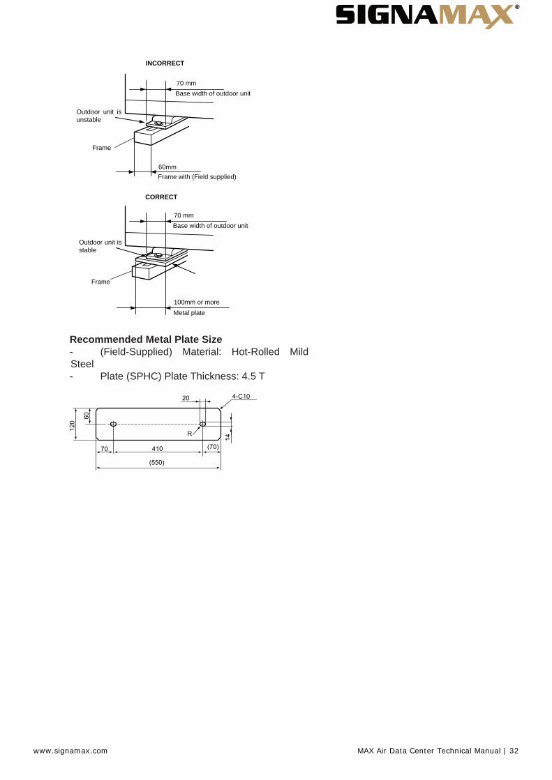
70 mmBase width of outdoor unit
Outdoor unit is unstable
Frame
60mmFrame with (Field supplied)
INCORRECT
CORRECT
Outdoor unit is stable
70 mmBase width of outdoor unit
Frame
100mm or moreMetal plate
Recommended Metal Plate Size- (Field-Supplied) Material: Hot-Rolled MildSteel- Plate (SPHC) Plate Thickness: 4.5 T
www.signamax.com MAX Air Data Center Technical Manual | 32
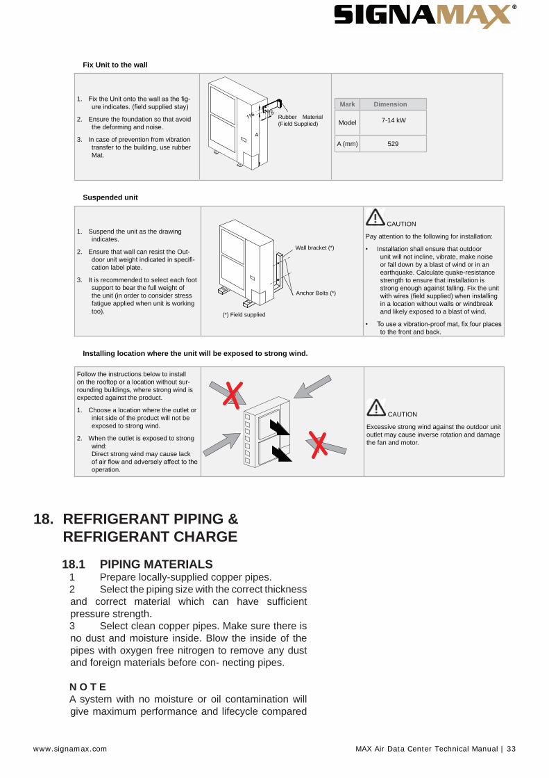
Fix Unit to the wall
1. -
2. Ensure the foundation so that avoid the deforming and noise.
3. In case of prevention from vibration transfer to the building, use rubber Mat.
Rubber Material (Field Supplied)
Mark Dimension
Model 7-14 kW
A (mm) 529
Suspended unit
1. Suspend the unit as the drawing indicates.
2. Ensure that wall can resist the Out--
cation label plate.
3. It is recommended to select each foot support to bear the full weight of the unit (in order to consider stress fatigue applied when unit is working too).
Wall bracket (*)
Anchor Bolts (*)
(*) Field supplied
CAUTION
Pay attention to the following for installation:
Installation shall ensure that outdoor unit will not incline, vibrate, make noise or fall down by a blast of wind or in an earthquake. Calculate quake-resistance strength to ensure that installation is strong enough against falling. Fix the unit
in a location without walls or windbreak and likely exposed to a blast of wind.
to the front and back.
Installing location where the unit will be exposed to strong wind.
Follow the instructions below to install on the rooftop or a location without sur-rounding buildings, where strong wind is expected against the product.
1. Choose a location where the outlet or inlet side of the product will not be exposed to strong wind.
2. When the outlet is exposed to strong wind: Direct strong wind may cause lack
operation.
CAUTION
Excessive strong wind against the outdoor unit outlet may cause inverse rotation and damage the fan and motor.
18. REFRIGERANT PIPING &REFRIGERANT CHARGE
18.1 PIPING MATERIALS1 Prepare locally-supplied copper pipes.2 Select the piping size with the correct thickness and correct material which can have suffi cient pressure strength.3 Select clean copper pipes. Make sure there is no dust and moisture inside. Blow the inside of the pipes with oxygen free nitrogen to remove any dust and foreign materials before con- necting pipes.
N O T EA system with no moisture or oil contamination will give maximum performance and lifecycle compared
www.signamax.com MAX Air Data Center Technical Manual | 33
to that of a poorly prepared system. Take particular care to ensure all copper piping is clean and dry internally.There is no refrigerant in the cycle of the indoor unit.
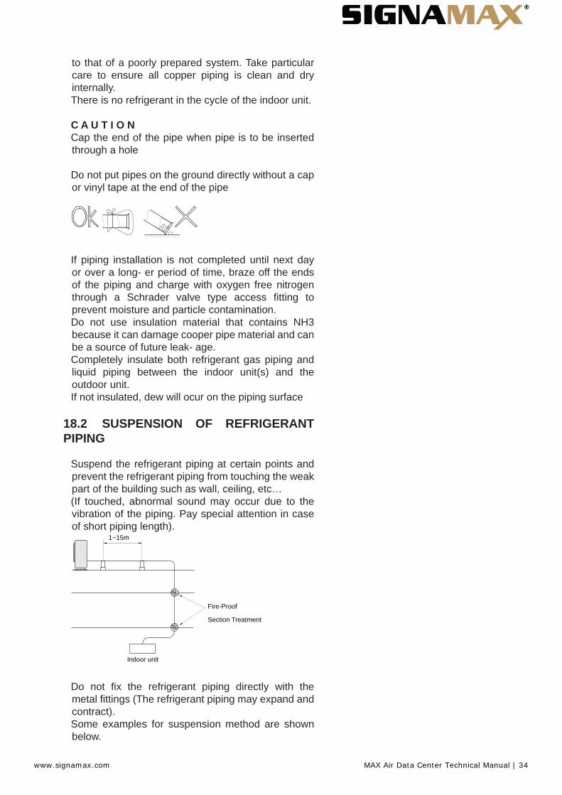
C A U T I O NCap the end of the pipe when pipe is to be inserted through a hole
Do not put pipes on the ground directly without a cap or vinyl tape at the end of the pipe
If piping installation is not completed until next day or over a long- er period of time, braze off the ends of the piping and charge with oxygen free nitrogen through a Schrader valve type access fi tting to prevent moisture and particle contamination.Do not use insulation material that contains NH3 because it can damage cooper pipe material and can be a source of future leak- age.Completely insulate both refrigerant gas piping and liquid piping between the indoor unit(s) and the outdoor unit.If not insulated, dew will ocur on the piping surface
18.2 SUSPENSION OF REFRIGERANT PIPING
Suspend the refrigerant piping at certain points and prevent the refrigerant piping from touching the weak part of the building such as wall, ceiling, etc…(If touched, abnormal sound may occur due to the vibration of the piping. Pay special attention in case of short piping length).
1~15m
Indoor unit
Fire-Proof
Section Treatment
Do not fi x the refrigerant piping directly with the metal fi ttings (The refrigerant piping may expand and contract).Some examples for suspension method are shown below.
www.signamax.com MAX Air Data Center Technical Manual | 34

For Suspending Heavies
For piping along the wall
For instant installation work
18.3 PIPING CONNECTION FOR OUTDOOR UNIT
1 The pipes can be connected from 4 directions. Make holes in the piping cover or cabinet for taking out pipes. Take the pip- ing cover away from the unit, and make holes by cutting along the guideline at the rear of the cover or punching with a driver. Remove the burr with a cutter, and place a insulation (fi eld supplied) to protect cables and pipes
(picture as example)
No Description1 Rear side piping work2 Pipe Cover3 Right side piping work4 Bottom side piping work (Knock out hole)5 Front side piping work6 Piping work7 Stop Valve8 Removing Direction for Service Cover
C A U T I O NNotes to open/close the service cover:• Remove the screws following the instructionsto the above fi gure.• Slowly press down the cover.NOTEHold the cover with a hand to remove screws as thecover may fall down.
www.signamax.com MAX Air Data Center Technical Manual | 35
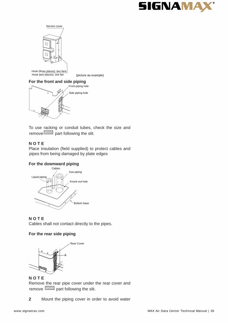
Service cover
Hook (three places): two fansHook (two places): one fan (picture as example)
For the front and side pipingFront piping hole
Side piping hole
To use racking or conduit tubes, check the size and remove part following the slit.
N O T EPlace insulation (fi eld supplied) to protect cables and pipes from being damaged by plate edges
For the downward piping
Gas piping
Knock-out hole
Bottom base
Cables
Liquid piping
N O T ECables shall not contact directly to the pipes.
For the rear side piping
Rear Cover
N O T ERemove the rear pipe cover under the rear cover and remove part following the slit.
2 Mount the piping cover in order to avoid water
www.signamax.com MAX Air Data Center Technical Manual | 36

entering into the unit. Seal the holes where pipes and wires are inserted, by using a insulation (fi eld-supplied).3 If the fi eld-supplied piping is connected with stop valves di- rectly, it is recommended use a tube bender.4 Check to ensure that the stop valves are closed completely before connecting pipes.5 Connect the fi eld supplied refrigerant pipes to the indoor unit and outdoor unit. Apply the oil thinly at the seat fl are nut and pipe before tightening.
The required tightening torque is as follows:
Pipe Size Tightening Torque (Nm)Ø 6.35 mm (1/4) 20Ø 9.53 mm (3/8) 40Ø 12.70 mm (1/2) 60Ø 15.88 mm (5/8) 80Ø 19.05 mm (3/4) 100
6 After connecting the refrigerant piping, seal the open space between knockout hole and refrigerant pipes by using insula- tion material
Unit Side
Nº Description
1 Insulation Material
2 Insulation Material
3 Field Supplied
4 Insulation Material
7 Operation of stop valve should be performed according to the fi gure below.Close before shipment
Outdoor unit stop valveSpindle Type
8-14 kW
1
2
3
4
www.signamax.com MAX Air Data Center Technical Manual | 37
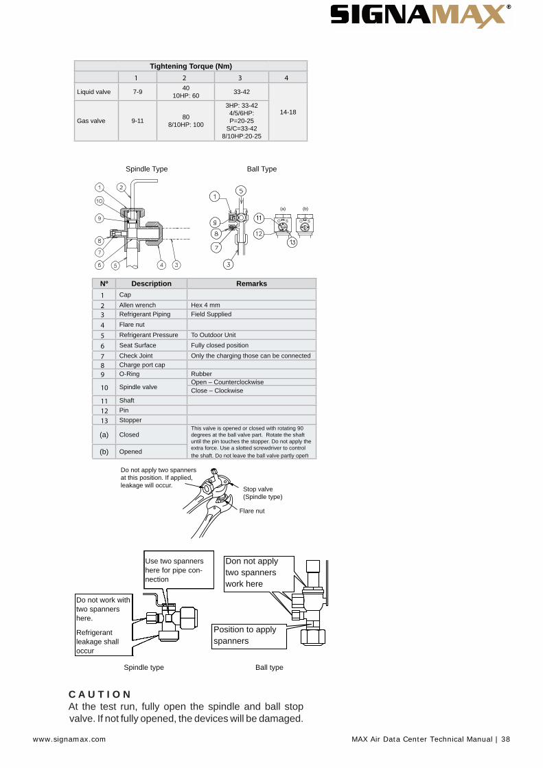
Tightening Torque (Nm)1 2 3 4
Liquid valve 7-9 40 10HP: 60 33-42
14-18Gas valve 9-11 80
8/10HP: 100
3HP: 33-42 4/5/6HP: P=20-25
S/C=33-42 8/10HP:20-25
Spindle Type Ball Type
(a) (b)
Nº Description Remarks1 Cap
2 Allen wrench Hex 4 mm3 Refrigerant Piping Field Supplied
4 Flare nut
5 Refrigerant Pressure To Outdoor Unit
6 Seat Surface Fully closed position
7 Check Joint Only the charging those can be connected8 Charge port cap9 O-Ring Rubber
10 Spindle valveOpen – CounterclockwiseClose – Clockwise
11 Shaft
12 Pin
13 Stopper
(a) ClosedThis valve is opened or closed with rotating 90 degrees at the ball valve part. Rotate the shaft until the pin touches the stopper. Do not apply the extra force. Use a slotted screwdriver to control the shaft. Do not leave the ball valve partly open(b) Opened
Do not apply two spanners at this position. If applied, leakage will occur. Stop valve
(Spindle type)
Flare nut
Use two spanners here for pipe con-nection
Do not work with two spanners here.
Refrigerant leakage shall occur
Position to apply spanners
Don not apply two spanners work here
Spindle type Ball type
C A U T I O NAt the test run, fully open the spindle and ball stop valve. If not fully opened, the devices will be damaged.
www.signamax.com MAX Air Data Center Technical Manual | 38
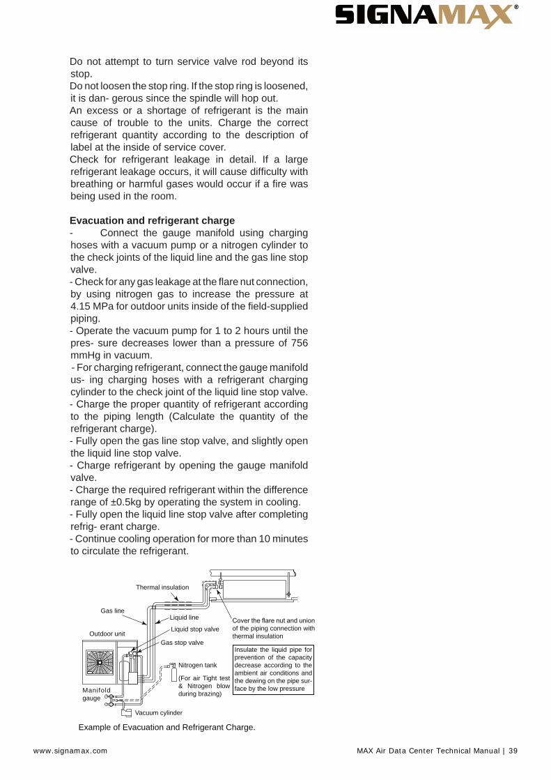
Do not attempt to turn service valve rod beyond its stop.Do not loosen the stop ring. If the stop ring is loosened, it is dan- gerous since the spindle will hop out.An excess or a shortage of refrigerant is the main cause of trouble to the units. Charge the correct refrigerant quantity according to the description of label at the inside of service cover.Check for refrigerant leakage in detail. If a large refrigerant leakage occurs, it will cause diffi culty with breathing or harmful gases would occur if a fi re was being used in the room.
Evacuation and refrigerant charge- Connect the gauge manifold using charginghoses with a vacuum pump or a nitrogen cylinder tothe check joints of the liquid line and the gas line stopvalve.- Check for any gas leakage at the fl are nut connection, by using nitrogen gas to increase the pressure at4.15 MPa for outdoor units inside of the fi eld-suppliedpiping.- Operate the vacuum pump for 1 to 2 hours until thepres- sure decreases lower than a pressure of 756mmHg in vacuum.- For charging refrigerant, connect the gauge manifold us- ing charging hoses with a refrigerant chargingcylinder to the check joint of the liquid line stop valve.- Charge the proper quantity of refrigerant accordingto the piping length (Calculate the quantity of therefrigerant charge).- Fully open the gas line stop valve, and slightly openthe liquid line stop valve.- Charge refrigerant by opening the gauge manifoldvalve.- Charge the required refrigerant within the differencerange of ±0.5kg by operating the system in cooling.- Fully open the liquid line stop valve after completingrefrig- erant charge.- Continue cooling operation for more than 10 minutesto circulate the refrigerant.
Thermal insulation
Gas line
of the piping connection with thermal insulation
Liquid line
Liquid stop valve
Gas stop valve
Nitrogen tank
(For air Tight test & Nitrogen blow during brazing)
Vacuum cylinder
Manifold gauge
Outdoor unit
Insulate the liquid pipe for prevention of the capacity decrease according to the ambient air conditions and the dewing on the pipe sur-face by the low pressure
Example of Evacuation and Refrigerant Charge.
www.signamax.com MAX Air Data Center Technical Manual | 39

18.4 Refrigerant chargeCAUTIONDo not charge OXYGEN, ACETYLENE, or other fl ammable and poisonous gases into the refrigerant because an explosion can occur. It is recommended that oxygen free nitrogen be charged for these types of tests cycle when performing a leakage test or an airtight test. These types of gases are extremely dangerous, Insulate the unions and fl are-nuts at the piping connection part completely.Insulate the liquid piping completely to avoid a decrease of performance;if not, it will cause sweating on the surface of the pipe.Charge refrigerant correctly. Overcharging or insuffi cient charging could cause a compressor failure. Check for refrigerant leakage in detail. If a large refrigerant leakage occurred, it would cause diffi culty with breathing or harmful gases would occur if a fi re were being used in the room.If the fl are nut is tigthened too hard, the fl are nut may crack after a long time and cause refrigerant leakage.
18.5 Caution of the pressure by check joint
When the pressure is measured, use the check joint of gas stop valve (A), and use the check joint of liquid piping (B) in the fi gure below.At that time, connect the pressure gauge according to the following table because of high pressure side and low pressure side changes by operation mode.
NOTEBe careful that refrigerant and oil do not splash to the electrical parts at removing the charge hoses.
C
B
A
The gas stayed at O-ring
sc rew pa r t i s opened
and may make sound
.pac eht gnivomer nehw
However, i t is not gas
leakage.
18.6 Refrigerant Charging QuantityOutdoor Units has been charged with refrigerant for 30m of actual piping length. An additional refrigerant charged is required in systems with actual piping length longer than 30m.1 Determine an additional refrigerant quantity according to the following procedure, and charge it into the system. 2 Record the additional refrigerant quantity to facilitate service activities thereafter.
www.signamax.com MAX Air Data Center Technical Manual | 40

CAUTIONWhen charging refrigerant accurately measure refrigerant to be charged.Overcharging or undercharging of refrigerant can cause compressor troubleIn case of actual piping length less than 5 m, consult your distributor.
18.7 ELECTRICAL WIRING CONNECTION FOR OUTDOOR UNITS
The electrical wiring connection for the outdoor unit isshown in fi gure below:
8-14 kW
Pow
er s
uppl
y 1~
230
V
Con
trol c
able
(5V
)
Table for Terminal Connection between unitsWiring System Units type Connection of
terminalsPower Supply DC inverter O.U. to O.U.
L1 to L1, L2 to L2, L3 to L3, N to N
I.U. to I.U.L1 to L1, N to N)
Operating DC inverter O.U. to I.U. or I.U. toI.U. 1 to1, 2 to 2
Remote Control DC inverter I.U. to I.U. A to A, B to B
www.signamax.com MAX Air Data Center Technical Manual | 41

18.7.3 Setting of DIP Switches for Outdoor Unit
Quantity and Position of DIP Switches. The location is as follows:
DSW1: For Test Run
Factory setting
DSW2: Optional Function Setting
Factory setting
Optional function setting
Optional function setting
1 2 4 6
ON
www.signamax.com MAX Air Data Center Technical Manual | 42
1 2 3 4 5 6
ON
1 2 3 4 5 6 1 2 3 4 5 6
ON
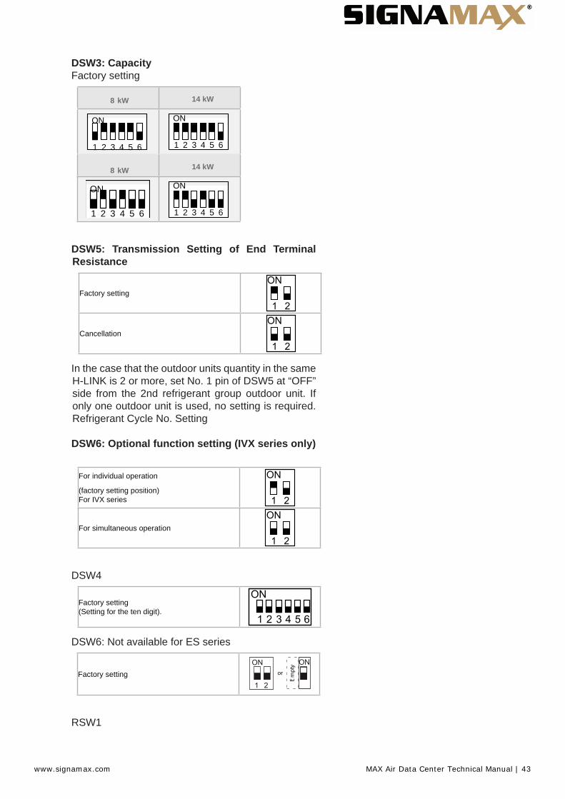
DSW3: CapacityFactory setting
8 kW
ON
1 2 3 4 5 6
8 kW
ON
14 kW
14 kW
DSW5: Transmission Setting of End Terminal Resistance
Factory setting
Cancellation
In the case that the outdoor units quantity in the same H-LINK is 2 or more, set No. 1 pin of DSW5 at “OFF”side from the 2nd refrigerant group outdoor unit. Ifonly one outdoor unit is used, no setting is required.Refrigerant Cycle No. Setting
DSW6: Optional function setting (IVX series only)
For individual operation
(factory setting position) For IVX series
For simultaneous operation
DSW4
Factory setting (Setting for the ten digit).
DSW6: Not available for ES series
Factory setting
tpm
Ey
or
RSW1
www.signamax.com MAX Air Data Center Technical Manual | 43

Factory setting
(Setting for the last digit).
0987 654321
1 2
DSW5
1 2
DSW5
1 2
DSW5
1 2
DSW5
( H-LINK) ( H-LINK) ( H-LINK)
18.7.4 System installation DIP Switch Setting
Dip Switch Setting of Indoor PCB and Outdoor PCB for H-LINK IIIt is required to set dip switches of every indoor unit and outdoor unit and match of the transmission circuit impedance.• Dip Switch Setting Example:
www.signamax.com MAX Air Data Center Technical Manual | 44
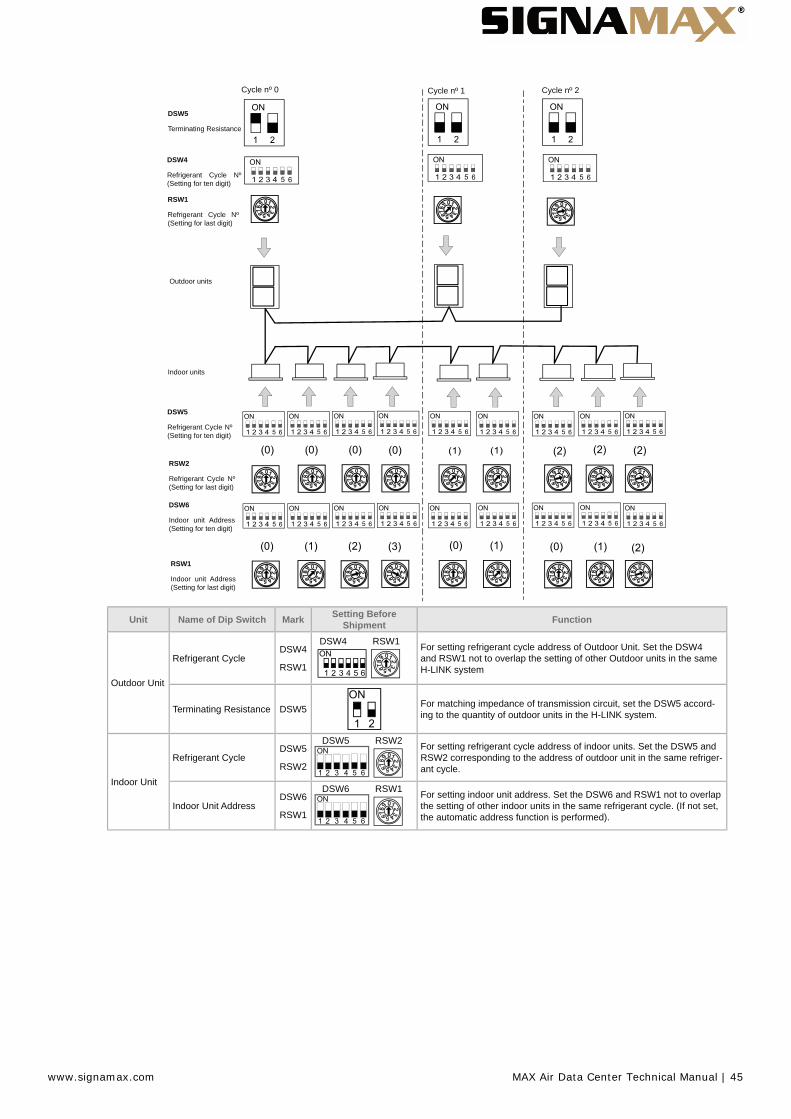
Cycle nº 0
DSW5
Terminating Resistance
DSW4
Refrigerant Cycle Nº (Setting for ten digit)
RSW1
Refrigerant Cycle Nº (Setting for last digit)
Outdoor units
Indoor units
DSW5
Refrigerant Cycle Nº (Setting for ten digit)
RSW2
Refrigerant Cycle Nº (Setting for last digit)
DSW6
Indoor unit Address (Setting for ten digit)
RSW1
Indoor unit Address (Setting for last digit)
Cycle nº 1 Cycle nº 2
Unit Name of Dip Switch Mark Setting Before Shipment Function
Outdoor Unit
Refrigerant CycleDSW4
RSW1
DSW4 RSW1 For setting refrigerant cycle address of Outdoor Unit. Set the DSW4 and RSW1 not to overlap the setting of other Outdoor units in the same H-LINK system
Terminating Resistance DSW5 For matching impedance of transmission circuit, set the DSW5 accord-ing to the quantity of outdoor units in the H-LINK system.
Indoor Unit
Refrigerant CycleDSW5
RSW2
DSW5 RSW2 For setting refrigerant cycle address of indoor units. Set the DSW5 and RSW2 corresponding to the address of outdoor unit in the same refriger-ant cycle.
Indoor Unit AddressDSW6
RSW1
DSW6 RSW1 For setting indoor unit address. Set the DSW6 and RSW1 not to overlap the setting of other indoor units in the same refrigerant cycle. (If not set, the automatic address function is performed).
www.signamax.com MAX Air Data Center Technical Manual | 45
19. TEST RUNNINGWhen installation is completed, perform test runaccording to the following procedure, and hand over the system to the customer. Perform test run regarding indoor units one by one in order, and confi rm that the electrical wiring and the refrigerant piping are correctly connected.Test run should be performed according to the Test Run Proce- dure on next page.
C A U T I O NDo not operate the system until all the check points have been cleared:• Check to ensure that the electrical resistanceis more than 1 MΩ, by measuring the resistancebetween ground and the terminal of the electricalparts. If not, do not operate the sys- tem until theelectrical leakage is found and repaired. Do notimpress the voltage on the terminals for transmission1 and 2.• Check to ensure that the stop valves of theoutdoor unit are fully opened, and then start thesystem.• Check to ensure that the switch on the mainpower source has been ON for more than 12 hours,to warm the compressor oil by the oil heaterPay attention to the following items while the systemis running:• Do not touch any of the parts by hand at thedischarge gas side, since the compressor chamberand the pipes at the dis- charge side are heatedhigher than 90°C.• DO NOT PUSH THE BUTTON OF THEMAGNETIC SWITCH(ES), it will cause a seriousaccident.• Do not touch any electrical components formore than three minutes after turning OFF the mainswitch• Confi rm that the gas line stop valve and theliquid line stop valve are fully open.• Confi rm that the leakage of the refrigerant doesnot exist. The fl are nuts are sometimes loosened byvibration during trans- portation.• Check that the refrigerant piping and theelectrical wiring con- form to the same system.• Confi rm that the dip switch setting on theprinted circuit board of the indoor units and theoutdoor units are correct.• Check whether or not the electrical wiring ofthe indoor units and the outdoor units are connectedas shown in the chapter Electrical Wiring.
www.signamax.com MAX Air Data Center Technical Manual | 46
19.1 TEST RUN PROCEDURE BY REMOTE CONTROL SWITCH (PC-ART EXAMPLE)
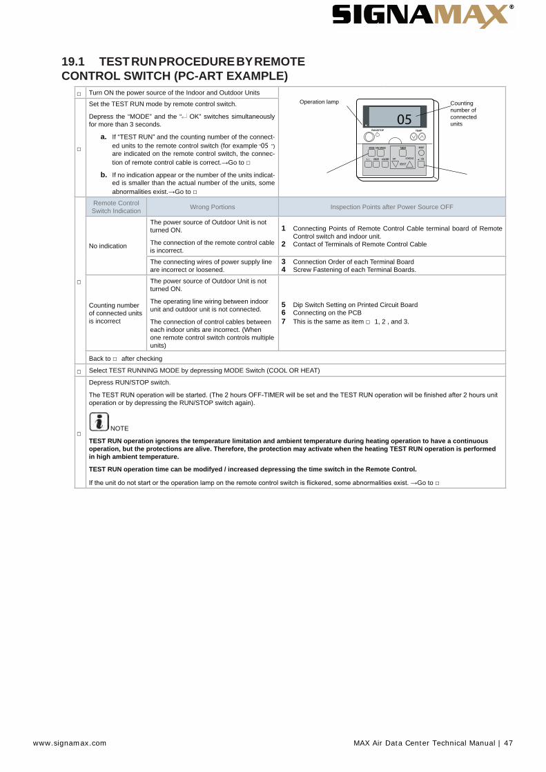
Turn ON the power source of the Indoor and Outdoor UnitsCounting number of connected units05
Operation lampSet the TEST RUN mode by remote control switch.
Depress the “MODE” and the “ OK” switches simultaneously for more than 3 seconds.
a. If “TEST RUN” and the counting number of the connect-ed units to the remote control switch (for example “05 ”)are indicated on the remote control switch, the connec-tion of remote control cable is correct. Go to
b. If no indication appear or the number of the units indicat-ed is smaller than the actual number of the units, someabnormalities exist. Go to
Remote Control Switch Indication Wrong Portions Inspection Points after Power Source OFF
No indication
The power source of Outdoor Unit is not turned ON.
The connection of the remote control cable is incorrect.
1 Connecting Points of Remote Control Cable terminal board of Remote Control switch and indoor unit.
2 Contact of Terminals of Remote Control Cable
The connecting wires of power supply line are incorrect or loosened.
3 Connection Order of each Terminal Board4 Screw Fastening of each Terminal Boards.
Counting number of connected units is incorrect
The power source of Outdoor Unit is not turned ON.
The operating line wiring between indoor unit and outdoor unit is not connected.
The connection of control cables between each indoor units are incorrect. (When one remote control switch controls multiple units)
5 Dip Switch Setting on Printed Circuit Board6 Connecting on the PCB7 This is the same as item 1, 2 , and 3.
Back to after checking
Select TEST RUNNING MODE by depressing MODE Switch (COOL OR HEAT)
Depress RUN/STOP switch.
operation or by depressing the RUN/STOP switch again).
NOTE
TEST RUN operation ignores the temperature limitation and ambient temperature during heating operation to have a continuous operation, but the protections are alive. Therefore, the protection may activate when the heating TEST RUN operation is performed in high ambient temperature.
TEST RUN operation time can be modifyed / increased depressing the time switch in the Remote Control.
Go to
www.signamax.com MAX Air Data Center Technical Manual | 47

6
Remote Control Switch Indication Unit Condition Wrong Portions Inspection Points after
Power Source OFF
-ers. (1 time/1 sec.) And the Unit No. and Alarm The unit does not start.
The power source of Outdoor Unit in not turned ON.
The connecting wires of operating line are incorrect or loosened.
1 Connecting Order of each Terminal Board.
2 Screw fastening of each Terminal Boards.
N O T ERecovering method of FUSE for oper-ating circuit. There is a fuse (FUSE4 on Indoor Unit PCB1, EF1 on Outdoor Unit PCB1) to protect operating cir-cuit on the PCB, when the power lines are connected to operating lines. If fuse is melted, operating circuit can be recovered once by setting the dip switch on the PCB as shown in 7
-ers. (1 time/2 sec.) The unit does not start.
Remote control cable is broken.
Contact of connectors is not good.
The connection of remote control cable is incorrect
This is the same as item 3 1 and 2
Indication of Flicker except above
The unit does not start, or start once and then stops
The connection of thermistor or other connectors are incorrect. Tripping of protector exists, or else.
Check by the abnormality mode table in the Technical Catalogue (Do it by serv-ice people).
The operation lamp Flickers. (1 Time/1s)
Unit No. 00 , Alarm Code and Unit Code E00
The unit does not start.The connection of the remote control cable between Indoor Units is incorrect.
Check by the abnormality mode table in the Technical Catalog (Do it by service people).
Back to 1 after checking
7
Instructions fot the recovery when the fuse of the transmission circuit is blown out:
1 Correct the wiring to the terminal board.2 Set the 1st pin of DSW7 on the indoor unit PCB to ON.
19.2 TEST RUN FROM OUTDOOR UNIT SIDE
The procedure of test run from outdoor unit side is indicated be- low. Setting of this DIP switch is available with the power source ON.Setting of Dip Switch (Before Shipment)
DSW1Switch for setting of Serivice Operation and Function
1 Test Run2 COOL/HEAT
Setting ON: Heat Operation3 OFF (Fixed)4 Manual Compressor stop
C A U T I O N• Do not touch any other electrical parts whenoperating switch-es on the PCB• Do not attach or detach service cover whenthe power source for the outdoor unit is ON and theoutdoor unit is operated.• Turn all DIP switches of DSW1 OFF when thetest run opera- tion is completed.
www.signamax.com MAX Air Data Center Technical Manual | 48

Operation Dip Switch Setting Operation Remarks
Test Run
1 Setting of Operation Mode:
Cooling: Set DSW1-2 OFF.
Heating: Set DSW1-2 ON.
2 Starting Test Run:
Set DSW1-1 ON and the operation is started after a few ~20 seconds.
Cooling Heating
1 The indoor unit automatically start to operate when the test run of the outdoor unit is set.
2 The ON/OFF operation can be per-formed from the remote control switch or DSW1-1 of the outdoor unit.
3 Continuous operation during 2 hours is performed without Thermo-OFF.
N O T ETEST RUN operation time can be increased depressing the time switch in the Remote Control.If is setting DSW1-3 ON, cool-ing/heating intermediate season mode is activaded.
Take care that the indoor units start op-eration in accord with the test run opera-tion of the outdoor unit.The test run is started from the outdoorunit and stopped from the remote con-trol switch, the test run function of theremote control switch is cancelled. How-ever, the test run function of the outdoorunit is not cancelledIn case that the plural indoor units areconnected with one remote controlswitch, all the units start test run opera-tion at the same time, therefore, turn thepower source OFF for the indoor unitsnot to operate test run. In this case, the“TEST RUN” indication of the remote
abnormal.The setting of DSW1 is not requiredfor the test run from the remote controlswitch.
Manual OFF of Compressor
1 Setting:
Compressor Manual OFF:
Set DSW1-4 ON.
Compressor ON:
Set DSW1-4 OFF.
1 When DSW1-4 is ON during com-pressor operation, the compressor stops to operate immediately and the indoor unit is under the condition of Thermo-OFF.
2 When DSW1-4 is OFF, the com-pressor starts to operate after the can-cellation of 3-minutes guard.
Do not repeat compressor ON/OFF fre-quently.
Manual Defrost
1 Manual Defrost Operation Starts
Press PSW1 for more than 3 seconds during heating operation, the defrost operation is started after 2 minutes.This function is not available within 5 minutes after starting heating operation
2 Manual Defrost Operation Finishes
Defrost operation is automatically ended and the heating operation is started.
1 Defrost operation is available re-gardless of frosting condition and total time of heating operation.
2 Defrost operation in not performed when the temperature of outdoor heat exchanger is higher than 10°C, high pressure is higher than 3.3 MPa (33kgf/cm2G) or Thermo-OFF.
Do not repeat defrost operation frequent-ly.
www.signamax.com MAX Air Data Center Technical Manual | 49

20. Specifi cations
Outdoor Unit 8 kW 14 kWPower supply 230V / 1Ph / 50Hz 230V / 1Ph / 50HzNominal Cooling Capacity (min - max) kW 7.1 (3.2 - 8.0) 12.5 (5.7 - 14.0)UK Cooling Capacity (sensible) (4) kW 7.7 (6.2) 13.2 (9.5)Minimum - Maximum Indoor Units* 1 - 2 1 - 4Minimum - Maximum connected capacity* 90%-110% 90% - 115%Seasonal Efficiency SEER (2) 5.31 n/a
Energy Efficiency Class A -Annual Energy Consumption kWh/yr 469 n/a
Seasonal Efficiency SCOP (2) (Average Climate) 4.07 n/aEnergy Efficiency Class A+ -
Annual Energy Consumption kWh/yr 1912 n/aNominal Load Efficiency EER / COP(3) 3.14 / 4.00 3.16 / 3.88
Energy Class (Cool/Heat) B / A B / ADimensions (H x W x D) mm 600x792x300 800x950x370Weight Kg 44 79
Piping diameter (Liquid / Gas)Inch 3/8 / 5/8 3/8 / 5/8mm 9.53 / 15.88 9.53 / 15.88
Minimum Piping Length m 5 5Maximum Piping Length / Height Difference m 50 / 30 75 / 30Working Range (cooling / heating) °C -5°C~46(db)°C / -20°C~15(wb)°C
* Restrictions apply please refer to Technical Catalogue(1) Sound power level is the A-weighted sound power level [dB(A)] measured at standard rated
conditions for the “cooling” mode operation in accordance to EN12102 (2) Data calculated in accordance to prEN14825 and the Commission Communication 2012/C 172/01(3) Nominal load efficiency (Cooling 35°C/27°C, Heating 7°C/20°C)(2, 3 & 4) Data specified includes connection to RCI-FSN3 indoor unit
Indoor Unit 7 kW
Nominal Cooling Capacity (1) kW 7.1
Noise Level (sound pressure) (L / M / H)(2) dB(A) 42/45/48
Noise level (sound power) dB(A) 65
Air flow cooling mode (L / M / H) m3/h 900/1020/1260
Included Condensate Pump no
Drain Diameter (ext) 25mm
Piping Diameter (Liquid / Gas)Inch 3/8 / 5/8
mm 9.53 / 15.88
Power Input W 170
Power supply 230V / 1Ph / 50Hz
Recommended fuse size A 5
14 kW
14.0
41/46/49
65
1260/1680/2100
no
25mm
3/8 / 5/8
9.53 / 15.88
230
230V / 1Ph / 50Hz
5
(1) Cooling: Internal ambient 27°C (19°C WB) - Ambient 35°C; Refrigerant piping length 7.5m, level difference 0m.(2) Sound pressure level measured at 1.5 meters below the unit (measured in anechoic room)
www.signamax.com MAX Air Data Center Technical Manual | 50

21. TROUBLESHOOTINGAlarm Code Indication of Remote Control Switch:
Abnormal Indoor Unit No.
Abnormal Ref. Cycle No. Alarm Code Model Code
Connected No. of Indoor Units
Alarm Code
Model Code
Indication Model
Heat-Pump
COOL MED ADDS. RN
A/C ALARM
Indicated for a sec-ond alter-
natelyCOOL MED ADDS. RN
A/C ALARM
InverterMulti (Set-Free)Cooling OnlyOthers2, 3 and 4 indoor units system
P
www.signamax.com MAX Air Data Center Technical Manual | 51

Code No. Category Content of Abnormality Leading Cause
01 Indoor Unit Tripping of Protection Device Failure of Fan Motor, Drain Discharge, PCB, Relay, Float Switch Activated
02 Outdoor Unit Tripping of Protection Device Activation of PSH, Locked Motor
03Transmission
Abnormality between Indoor (or Outdoor) and Outdoor (or Indoor)
Incorrect Wiring, Failure of PCB, Tripping of Fuse, Power Supply OFF
04 Abnormality between Inverter and Control PCB Failure in Transmission between PCBs for Inverter
05 Power Supply Abnormality power supply Abnormal wave form of power supply.
06 Voltage Drop Voltage Drop by Excessively Low or High Volt-age to Outdoor Unit
-ity of Power Supply Wiring
07Cycle
Decrease in Discharge Gas Superheat Excessive Refrigerant Charge, Expansion Valve Open Lock
08 Increase in Discharge Gas Temperature Close Lock
11
Sensor on Indoor Unit
Inlet Air Thermistor
Failure of Thermistor, Sensor, Connection.12 Outlet Air Thermistor
13 Freeze Protection Thermistor
14 Gas Piping Thermistor
19 Tripping of Protection Device for Fan Motor Failure of Fan Motor
20
Sensor on Outdoor Unit
Compressor Thermistor
Failure of Thermistor, Sensor, Connection
(Incorrect Wiring, disconnecting wiring, breaking wire, short circuit)
21 High Pressure Sensor
22 Out+door Air Thermistor
24 Evaporating Thermistor
31
System
Incorrect Setting of Outdoor and Indoor Unit Incorrect Setting of Capacity Code.
35 Incorrect Setting in Indoor Unit No. -tions.
38 Abnormality of Protective Circuit in Outdoor Unit Failure of Indoor Unit PCB. Incorrect wiring. Connection to PCB in Indoor Unit.
45
Pressure
Activation of High Pressure Increase Protection Device
Overload Operation (Clogging, Short-Pass), Pipe Clogging, Exces-sive Refrigerant, Inert Gas Mixing
47 Activation of Low Pressure Decrease Protection Device
Stoppage by Excessively Decrease of evaporating Temperature (Te < -35ºC) is activated 3 times in one hour, Locked Motor in Heat-ing Operation.
48
Inverter
Activation of overload protection Failure of IPM or PCB2, heat exchanger clogged, locked compres-sor, EVI/EVO failure or overcharge.
51 Abnormality of Current Sensor for Inverter Failure of Control PCB, Inverter Module.
53 Protection Activation of Transistor Module Transistor Module Abnormality. Failure of Compressor, clogging of Heat Exchanger.
54 Inverter Fin Temperature Increase
Abnormal Inverter Fin Thermistor.
Clogging of Heat Exchanger
Abnormal Outdoor Fan
55 Inverter Module Abnormality Failure of Inverter Module.
57 Outdoor Fan Fan Motor AbnormalityDisconnected wire of Incorrect wiring between Control PCB and Inverter PCB.
Incorrect Wiring or Fan Motor Abnormality
b1 Indoor unit No. setting
Incorrect address No. Setting or refrigerant cycle Over 64 indoor units setting by No. or indoor unit address.
EE Compressor Compressor protection alarm Failure of compressor.
www.signamax.com MAX Air Data Center Technical Manual | 52

www.signamax.com
CONNECT WITH US
Signamax Corporate999 NW 159th Dr, Miami, FL 33169 800.446.2377
Bibra Lake, WA 6163 AustraliaT: +61 89 202 800E: [email protected]
INDIAA-74 FIEE Complex, OKHLAIndust. Park Phase II NewDelhi, 110020IndiaT: +91 114 106 9843E: [email protected]
AUSTRALIA8 Port Kembla Dr, Perth,
MIDDLE EASTNo 3 Reviera Hotel, Baniyas Rd, Deira, DubaiUnited Arab Emirates T: +97 155 424 2722 E: [email protected]
SOUTH EAST ASIA 55 UBI Ave 1,#02-10 UBI 55 Singapore, 408935 T: +65 6925 5798 E:[email protected]
CANADA2-975 Bleams Rd, Kitchener,Ontario CanadaN2E3Z5T: +1 519 570 3911 E:[email protected]
MALAYSIASuite 1.2, 1st Floor Bangunan THK No.2A Jalan 243 Seksyen 51a46100 Petaling Jaya, Selangor, Malaysia T: +60 3-7873 7317 E: [email protected]
SRI LANKA49 Sri Jinarathana Rd Colombo 2,Sri LankaT: +94 114 792 100 E: [email protected]
UK7-10 Chandos Street,London, W1G 9DQUnited KingdomT: +44 20 358 22933E: [email protected]
International Sales Offices: