Operating and Installation Instructions Ventilation Hood steel housing ... Air venting ... – 1)...
52
Operating and Installation Instructions Ventilation Hood To prevent accidents and damage to the appliance, you must read these instructions before installing the appliance and using it for the first time. en-US M.-Nr. 10 118 580
-
Upload
nguyenngoc -
Category
Documents
-
view
217 -
download
0
Transcript of Operating and Installation Instructions Ventilation Hood steel housing ... Air venting ... – 1)...

Operating and Installation InstructionsVentilation Hood
To prevent accidents and damage to the appliance, you must readthese instructions before installing the appliance and using it for the firsttime.
en-US M.-Nr. 10 118 580

Contents
2
IMPORTANT SAFETY INSTRUCTIONS ................................................................ 4
Caring for the environment ................................................................................ 13
Description of functions ..................................................................................... 14Con@ctivity 2.0 function........................................................................................ 15
Guide to the appliance ........................................................................................ 16
Operation (Automatic mode) .............................................................................. 18Cooking with Con@ctivity 2.0 (Automatic mode) .................................................. 18Temporarily exiting Automatic mode..................................................................... 20Resuming Automatic mode................................................................................... 20
Operation (Manual mode) ................................................................................... 21Cooking without Con@ctivity 2.0 (Manual mode) ................................................. 21Turning on the fan.................................................................................................. 21Selecting the power level ...................................................................................... 21Selecting the Delayed shut down time.................................................................. 21Turning off the fan ................................................................................................. 21Turning the overhead lighting on/off...................................................................... 22Power management .............................................................................................. 22
Operation (Automatic and Manual modes) ....................................................... 23Filter saturation indicator....................................................................................... 23
Adjusting the filter saturation indicator for grease filters.................................. 23Checking the filter saturation indicator............................................................. 24
Adjusting the height of the canopy ....................................................................... 24
Cleaning and care ............................................................................................... 25Stainless steel housing.......................................................................................... 25Grease filters ......................................................................................................... 26
Installation............................................................................................................ 29Before installation.................................................................................................. 29Installation parts .................................................................................................... 29Appliance dimensions ........................................................................................... 30Distance between cooktop and ventilation hood (S)............................................. 31Installation recommendations ............................................................................... 32Structural support ................................................................................................. 32Removing the protective film................................................................................. 32
Air venting ............................................................................................................ 42Condensate trap.................................................................................................... 43

Contents
3
Electrical connection .......................................................................................... 44Grounding Instructions.......................................................................................... 44
Activating Con@ctivity 2.0 .................................................................................. 45Installation of the Con@ctivity 2.0 stick................................................................. 45Activating the Con@ctivity 2.0 function................................................................. 45
Activating the ventilation hood......................................................................... 45Activating the cooktop ..................................................................................... 46Activation failed................................................................................................ 46
Deactivating Con@ctivity 2.0................................................................................. 46
Service and warranty .......................................................................................... 47Location of the data plate ..................................................................................... 47
Technical data ..................................................................................................... 48
IMPORTANT SAFETY INSTRUCTIONS
4
READ AND SAVE THESE INSTRUCTIONS
This appliance complies with current safety requirements.Improper use of the appliance can lead to personal injury andmaterial damage.
Read all instructions before installing or using the appliance for thefirst time. Only use the appliance for its intended purpose.
Keep these operating instructions in a safe place and pass themon to any future user.
Use
CAUTION: For General Ventilating Use Only. Do Not Use ToExhaust Hazardous Or Explosive Materials And Vapors.
This appliance is intended for residential use only. Use only asdescribed in these operating instructions.
This ventilation hood is designed for domestic use and for use insimilar residential environments.
This ventilation hood is not intended for outdoor use.
It must only be used to extract and clean vapors produced duringcooking. Any other use occurs at the owner's own risk.
This appliance is suitable for installation above gas or electriccooking surfaces.
Persons who lack physical, sensory or mental abilities, orexperience with the appliance should not use it without supervisionor instruction by a responsible person.

IMPORTANT SAFETY INSTRUCTIONS
5
Children
As with any appliance, close supervision is necessary when usedby children.
Please supervise children in the vicinity of the hood and do not letthem play with it.
Danger of suffocation! Ensure that any plastic wrappings, bags,etc. are disposed of safely and kept out of the reach of children.
Technical safety
WARNING: TO REDUCE THE RISK OF FIRE, ELECTRIC SHOCK,OR INJURY TO PERSONS, OBSERVE THE FOLLOWING:
– Use this appliance only in the manner intended by themanufacturer. If you have questions, contact Miele.
– Before servicing or cleaning the appliance, switch power off at theservice panel and lock the service disconnecting means toprevent power from being switched on accidentally. If the servicedisconnecting means cannot be locked, securely fasten aprominent warning device, such as a tag, to the service panel.
Installation, repair and maintenance work should be performed bya Miele authorized service technician in accordance with nationaland local safety regulations and the provided installationinstructions. Contact Miele’s Technical Service Department forexamination, repair or adjustment. Repairs and other work byunauthorized persons could be dangerous and may void thewarranty.
A damaged ventilation hood can be dangerous. Always check forvisible signs of damage. Never use a damaged ventilation hood.

IMPORTANT SAFETY INSTRUCTIONS
6
Be certain your appliance is properly installed and grounded by aqualified technician. To guarantee the electrical safety of thisappliance, continuity must exist between the appliance and aneffective grounding system. It is imperative that this basic safetyrequirement be met. If there is any doubt, have the electrical systemof the house checked by a qualified electrician.
Reliable and safe operation of this hood can only be guaranteed ifit has been connected to the electrical supply.
To avoid damaging the ventilation hood, make sure that theconnection data (voltage and frequency) on the data platecorrespond to the building's power supply before connecting theappliance. When in doubt, consult a qualified electrician.
Do not use a power bar or extension cord to connect theventilation hood to electricity. These are a fire hazard and do notguarantee the required level of appliance safety.
To ensure safe operation, only use the ventilation hood after it hasbeen properly installed.
This ventilation hood may not be used in non-stationary locations(e.g. on a ship).
Adequate ventilation must be provided when the hood is operatedsimultaneously with devices that burn gas or other fuels.
Only open the housing as described in the enclosed "Installationdiagram" and in the "Cleaning and care" section of this manual.Under no circumstances should any other parts of the housing beopened.Tampering with electrical connections or components andmechanical parts is highly dangerous to the user and can causeoperation faults.
Defective components should be replaced by Miele original partsonly. Only with these parts can the manufacturer guarantee thesafety of the appliance.

IMPORTANT SAFETY INSTRUCTIONS
7
During installation, maintenance, and repair work, the ventilationhood must be disconnected from the electrical supply. It is onlycompletely isolated from the electricity supply if one of the followingapplies:
– The circuit breakers on the electrical service panel are tripped.
– The screw-type fuses on the electrical service panel have beenremoved.
– The power cable (if present) has been unplugged from the socket(pull the plug not the cord).

IMPORTANT SAFETY INSTRUCTIONS
8
Proper use
WARNING: TO REDUCE THE RISK OF A COOKTOP GREASEFIRE:
– a) Never leave surface units unattended at high settings. Boiloverscause smoking and greasy spillovers may ignite. Heat oils slowlyon low or medium settings.
– b) Always turn the hood on when cooking at a high heat.
– c) Clean the ventilation hood frequently. Grease should not beallowed to accumulate on the fan or filter.
– d) Use the proper pan size. Always use cookware appropriate forthe size of the cooking area.
Never use an open flame beneath the ventilation hood.To avoid the risk of fire, do not flambé or grill over an open flame.When turned on, the ventilation hood will draw any flames into thefilter. Fat deposits may ignite.
WARNING: TO REDUCE THE RISK OF INJURY TO PERSONS INTHE EVENT OF A COOKTOP GREASE FIRE, OBSERVE THEFOLLOWING*:
– a) SMOTHER FLAMES with a close fitting lid, cookie sheet, ormetal tray then turn off the burner. BE CAREFUL TO PREVENTBURNS. If the flames do not go out immediately, EVACUATE ANDCALL THE FIRE DEPARTMENT.
– b) NEVER PICK UP A FLAMING PAN - You may be burned.
– c) DO NOT USE WATER, including wet dishcloths or towels - aviolent steam explosion will result.
– d) Use a fire extinguisher ONLY if:– 1) You have a class ABC extinguisher, and you know how to operate it.
– 2) The fire is small and contained in the area where it started.
– 3) The fire department is being called.
– 4) You can fight the fire with your back to an exit.
*Based on "Kitchen Fire Safety Tips" published by NFPA.

IMPORTANT SAFETY INSTRUCTIONS
9
The ventilation hood may become damaged if exposed toexcessive heat from a gas cooktop.
– When using the ventilation hood over a gas cooktop, ensure thatany burners in use are always covered by cookware. Turn burnersoff when removing the cookware, even if doing so for just a shorttime.
– Select cookware that is suitable for the size of the burner.
– Adjust the flame so that it never extends up the sides of thecookware.
– Avoid overheating the cookware (e.g., when cooking with a wok).
Always turn the ventilation hood on whenever a burner is in use toprevent damage from condensation.
Overheated oils and fats can ignite and set the ventilation hood onfire.When cooking with oils or fats, do not leave pots, pans or fryersunattended. Never leave an electric grill unattended when grilling.
Fat and debris deposits impair the proper functioning of theventilation hood.To ensure that cooking vapors are properly cleaned, never use theventilation hood without the grease filters in place.
There is a risk of fire if cleaning is not completed according to theinstructions in this manual.
Please note that the heat rising from the stovetop during cookingcan cause the ventilation hood to become very hot.Do not touch the housing or the grease filters until the ventilationhood has cooled down.

IMPORTANT SAFETY INSTRUCTIONS
10
Proper installation
WARNING: TO REDUCE THE RISK OF FIRE, ELECTRIC SHOCK,OR INJURY TO PERSONS, OBSERVE THE FOLLOWING:
– a) Installation work and electrical wiring must be done by qualifiedperson(s) in accordance with all applicable codes and standards,including fire-rated construction.
– b) Sufficient air is needed for combustion and exhausting of gasesthrough the flue (chimney of fuel burning equipment to preventback drafting. Follow the heating equipment manufacturer’sguideline and safety standards such as those published by theNational Fire Protection Association (NFPA) and the AmericanSociety for Heating, Refrigeration and Air Conditioning Engineers(ASHRAE), and the local code authorities.
– c) When cutting or drilling into the wall or ceiling, do not damageelectrical wiring and other hidden utilities.
– d) Ducted hoods must always be vented to the outdoors.
– e) Do not use this hood with any solid-state speed control device.
To determine whether a ventilation hood may be operated aboveyour cooking appliance, please refer to the information provided bythe appliance's manufacturer.
Safety regulations prohibit the installation of a ventilation hoodabove solid fuel stoves.
Insufficient distance between the cooking appliance and theventilation hood can result in damage to the hood.The minimum safety distances between the appliance and thebottom of the ventilation hood specified in the "Installation" sectionmust be maintained, unless the appliance's manufacturer hasindicated that a greater distance is required.If more than one cooking appliance is used beneath the ventilationhood, and if different minimum safety distances apply for theseappliances, you should use the greater distance.

IMPORTANT SAFETY INSTRUCTIONS
11
Be sure to observe the information contained in the "Installation"section when mounting the ventilation hood.
Metal parts can have sharp edges which may cause injury.Wear gloves to protect your hands from being cut.
When installing the exhaust duct, only use pipes or tubes made ofnon-flammable material. These can be obtained from your Mieledealer or from Miele Technical Service.
Exhaust air should not be vented into a chimney or vent flue whichis otherwise in use and should not be channeled into ducting whichventilates rooms with fuel-burning installations.
If exhaust air is to be extracted into a chimney or vent flue nolonger used for other purposes, be sure to comply with all applicableregulations.
WARNING: TO REDUCE THE RISK OF FIRE USE ONLY METALDUCTWORK.
Cleaning and care
Never use a steam cleaner to clean the ventilation hood.The steam can reach the electrical components and cause a shortcircuit.
Accessories
Use only genuine original Miele parts. If parts or accessories fromother manufacturers are used, the warranty will become void.

IMPORTANT SAFETY INSTRUCTIONS
12
FCC Declaration of Conformity
These devices comply with FCC Rules Part 15. This equipmenthas been tested and found to be in compliance with the limits for aClass B digital device, pursuant to Part 15 of the FCC Rules ofOperation and is subject to the following conditions:These devices may not cause harmful interference.These devices must accept any interference received, includinginterference that may cause undesired operation.
FCC Radiation Exposure Statement
This equipment complies with FCC radiation exposure limits setforth for an uncontrolled environment. This equipment should beinstalled and operated with minimum distance 8" (20 cm) betweenthe radiator and your body.
Industry Canada Statement
This digital apparatus does not exceed the Class B limits forRadio Noise Emissions from digital apparatus set out in the RadioInterference Regulations of the Canadian Department ofCommunications.
Complies with Canadian ICES-003 Class B specifications.

Caring for the environment
13
Disposal of the packingmaterialThe cardboard box and packingmaterials protect the appliance duringshipping. They have been designed tobe biodegradable and recyclable.
Ensure that any plastic wrappings,bags, etc. are disposed of safely andkept out of the reach of children.Danger of suffocation!
Disposal of your old applianceDo not dispose of this appliance withyour household waste.
Old appliances may contain materialsthat can be recycled. Please contactyour local recycling authority about thepossibility of recycling these materials.
Before discarding an old applianceensure that it presents no danger tochildren while being stored for disposal.Unplug it from the outlet, cut off itspower cord and remove any doors toprevent hazards.

Description of functions
14
The following functions are available onyour ventilation hood, depending on themodel:
Vented mode
The air is drawn in and cleaned by thegrease filters and directed outside.
Non-return flap
A non-return flap in the ductingprevents the exchange of inside andoutside air from occurring when theventilation hood is not in use.The flap is closed when the ventilationhood is turned off.When the ventilation hood is turned on,the non-return flap opens so that theexhaust air can be transported outsidewithout any obstruction.
A non-return flap has been providedwith the hood in case your ducting doesnot have one. It is inserted into theoutlet duct collar of the fan.

Description of functions
15
Con@ctivity 2.0 functionAutomatic control
This hood features a communicationfunction which enables the automaticcontrol of the hood based on theoperational status of a Miele inductioncooktop.
To enable the communication function,the cooktop must be equipped with thecorresponding Con@ctivity 2.0 stick .
Please refer to the installationinstructions for the Con@ctivity 2.0stick to determine whether connectionto your cooktop is possible.
There must be radio contact betweenthe cooktop and the hood for you to beable to use the Con@ctivity 2.0 function(see "Activating Con@ctivity 2.0").
The cooktop transmits informationabout its operational status to the hoodusing a radio signal.
– When a burner is turned on, thecooktop lighting on the hood turns onautomatically. After a brief delay, theventilation hood fan also comes on.
– During cooking, the hoodautomatically selects the fan levelbased on the number of burners inoperation and their power levels.
– Once you have turned off thecooktop, the fan and the lighting willturn off automatically after apredetermined delay.
Detailed information about this functioncan be found under "Operation."

Guide to the appliance
16
5 151 2 3 IS

Guide to the appliance
17
a Telescopic chimney
b Chimney
c Height-adjustable canopy
d Control panel
e Grease filters
f Spacer frameThe spacer frame creates a shadow gap between the chimney and the ceiling.The hood can be installed with or without the spacer frame.
g Overhead lighting
h Overhead lighting button
i On/Off button for fan
j Fan power selection
k Delayed shut down button
l Operating hours button
m Controls for raising and lowering the canopy

Operation (Automatic mode)
18
When Con@ctivity 2.0 is active, thehood always operates in Automaticmode (see "Activating [email protected]").
See "Cooking without Con@ctivity 2.0"for information on manually operatingthe hood.
Cooking with Con@ctivity 2.0(Automatic mode) Turn on a burner to the desired power
setting.
Overhead cooktop lighting.
After a few seconds, the fan will comeon, briefly operating at power level 2before immediately switching to level 1.
The hood selects the fan levelautomatically during cooking.
This level is determined by the totaloutput of the cooktop, i.e. the numberof burners in operation and the powersettings selected.
If you select a higher power settingon the cooktop or switch on multipleburners, the hood will switch to ahigher fan level.
If you select a lower power setting onthe cooktop or turn off a burner, thehood will accordingly switch to alower fan level.
Examples for fan levels 1 to 4
Reaction timeChanging the power setting on thecooktop does not lead to an immediateincrease or decrease in cooking vapors.For this reason, the hood reacts with aslight delay.
Delays can also result from the fact thatthe cooktop transmits the information tothe hood in intervals.
The reaction time can vary from a fewseconds to a couple of minutes.

Operation (Automatic mode)
19
Cooking process If, for example, you switch on a
burner at the highest power setting toheat cookware in preparation forsearing and then reduce the powerlevel after approx. 60 to 90 seconds,a cooking process is recognized.
The hood turns on automatically and,after the cooktop power level has beenreduced, switches back to fan level 3,where it remains for approx. 5 minutes.
After this, the fan level is once againdetermined by the Con@ctivity function.
You can also manually select adifferent fan level before then.
Deactivation Turn off all burners.
Over the next few minutes, theventilation hood fan setting willdecrease one level at a time until thehood eventually turns off.
This helps to neutralize any lingeringvapors and odors in the air.
– From the intensive setting, the fanimmediately switches to level 3.
– If the fan is operating at level 3, it willswitch to level 2 after approx. 1minute.
– From level 2, the fan switches to level1 after 2 minutes.
– After 2 minutes at level 1, the fanautomatically turns off.
– After another 30 seconds, theoverhead cooktop lighting turns off.
The cooking process is now finished.

Operation (Automatic mode)
20
Temporarily exiting AutomaticmodeTo temporarily exit the Automatic modewhen cooking:
Manually select a different fan level,or
Manually turn the hood off, or
Activate the Delayed shut downfunction on the ventilation hood.The fan turns off after the delay timeselected, and the lighting will remainon.
The ventilation hood functions can nowbe operated manually (see "Cookingwithout Con@ctivity 2.0").
Resuming Automatic modeThe ventilation hood resumesAutomatic mode:
If the ventilation hood has not beenused for a period of approx. 5minutes after the manual selection ofa fan level, or
If the manually selected fan levelonce again matches the automaticsetting, or
If the ventilation hood fan and thecooktop have been turned off for atleast 30 seconds.Automatic mode will resume the nexttime the cooktop is turned on.
If you wish to manually operate theventilation hood for a completecooking process, turn on theventilation hood fan before turningon the cooktop.If the ventilation hood and thecooktop have been turned off for atleast 30 seconds after you havefinished cooking, Automatic modewill resume the next time the cooktopis turned on.
Operation (Manual mode)
21
Cooking without [email protected] (Manual mode)The hood can be operated manually if:
– The Con@ctivity 2.0 function is notactivated.
– You have temporarily deactivated theCon@ctivity 2.0 function (see"Temporarily exiting Automaticmode").
Turning on the fan Press the On/Off button .
The fan turns on at level 2. The symbol and 2 will light up in the fanlevel display.
Selecting the power levelPower levels 1 to 3 can be used for lightto heavy cooking vapors and odors.
For strong vapors and odors that aretemporarily produced when cooking,e.g. during searing, select the IS levelas an intensive setting.
Press the "" button for a lowerpower level or the "" button toselect a higher level.
Reducing power of the intensivesetting
If power management is activated(default setting), the fan automaticallyswitches back to level 3 after 5 minutes.
Selecting the Delayed shutdown timeIt is a good idea to let the fan run for afew more minutes after cooking in orderto neutralize any lingering vapors andodors in the air.With the Delayed shut down function, itis possible to have the fan automaticallyshut off after a predetermined period oftime.
After you have finished cooking,press the Delayed shut down button5 15
– Once: fan turns off after 5 minutes (5lights up).
– Twice: fan turns off after 15 minutes(15 lights up).
– If you press the Delayed shut downbutton 515 again, the fan remainsturned on (515 goes out).
Turning off the fan Press the On/Off button to turn the
fan off.
The symbol will go out.

Operation (Manual mode)
22
Turning the overhead lightingon/offThe overhead lighting can be turned onand off separately from the fan.
To do so, press the button.
The symbol is lit when the overheadlighting is turned on.
Power managementThe ventilation hood features a powermanagement system to help saveenergy. The fan power level is reducedand the lighting is turned offautomatically.
– If the intensive setting is selected, thefan automatically switches to level 3after 5 minutes.
– If the fan is set to level 3, 2 or 1, itswitches back one fan setting after 2hours and then in 30-minute intervalsuntil the fan eventually switches off.
– If the overhead lighting is on, itautomatically turns off after 12 hours.
Turning power management On/Off
You can deactivate the powermanagement.This can result in increased electricityconsumption.
Turn off the fan and the lighting.
Press and hold the Delayed shutdown button 5 15 for approx. 10seconds until 1 appears in the fanlevel display.
Then, press the following buttons inorder:
– The lighting button ,
– Followed by the "" button and then
– The lighting button again.
If power management is turned on, the1 and IS indicators will be continuouslylit.If it is turned off, 1 and IS will flash.
Press the "" button to turn powermanagement off.
The 1 and IS indicators will flash.
To turn it on, press the "" button.
The 1 and IS indicators are constantlylit.
Confirm the setting by pressing theDelayed shut down button 5 15.
All the indicator lights go out.
If the new setting is not confirmedwithin 4 minutes, the hood reverts tothe previous setting.

Operation (Automatic and Manual modes)
23
Filter saturation indicatorThe number of hours the hood hasbeen in operation is stored in appliancememory.
When the grease filter symbol , lightsup, the filter saturation indicator issignaling that the filters need to becleaned or changed. Additionalinformation about cleaning andchanging the filters and resetting thefilter saturation indicator can be foundunder "Cleaning and care."
Adjusting the filter saturationindicator for grease filters
You can set the filter saturationindicator to suit your cooking habits.
The factory default setting is an intervalof 30 hours.
– Select a shorter time (20 hours) if youoften fry foods.
– We also recommend a shortercleaning interval if you only cookoccasionally. This will prevent greasebuildup from hardening and makingcleaning more difficult.
– Select a longer cleaning interval of 40or 50 hours if you use very little fatwhen cooking.
Press the On/Off button to turn thefan off.
Press the Delayed shut down button515 and the filter saturation button at the same time.
The grease filter symbol on the filtersaturation button and one of the fanpower level indicators will flash.
Fan power level indicators 1 to IS showthe current time setting:
Indicator 1 ............................... 20 hours
Indicator 2 ............................... 30 hours
Indicator 3 ............................... 40 hours
Indicator IS .............................. 50 hours
Press the "" symbol for a shorteroperating time, or the "" symbol toselect a longer operating time.
Confirm the selection by pressing thefilter saturation indicator .
All the indicator lights will go out.
If the setting is not confirmed within 4minutes, the ventilation hoodautomatically reverts to the old setting.

Operation (Automatic and Manual modes)
24
Checking the filter saturationindicator
Before the set operating time has runout, you can check what percentage ofthe time has elapsed.
Press the On/Off button to turn thefan on.
Press and hold the operating hoursbutton :
The grease filter symbol lights up.
One or more of the fan power levelindicators will flash simultaneously.
The number of flashing indicatorsshows the elapsed operating hours as apercentage.
Indicator 1 .................................... 25%
Indicators 1 and 2 ......................... 50%
Indicators 1 to 3 ........................... 75%
Indicators 1 to IS ........................ 100%
The elapsed operating hours remainstored in the memory when the hoodis turned off or if power to theappliance is lost.
Adjusting the height of thecanopyThe height adjustment feature on thecanopy can be used to:
– adapt the height of the hood to suitthe installation conditions.
– adjust the working area underneaththe hood to the height of the user.
– maximize steam extraction bylowering the steam during particularlyintensive cooking.
– create more working space above thecooktop by raising the canopy whenrequired.
The canopy can be raised or loweredby pressing the controls briefly.
Pressing one of the controls againstops the canopy.
If it is not stopped, the canopy willautomatically be raised or lowered to itsfullest extent.
Repeated use of the heightadjustment feature over severalminutes will cause it to cut out.It can be used again after a pause.

Cleaning and care
25
Stainless steel housing
General information
The surfaces and control buttons aresusceptible to scratching andchipping.Observe the following cleaninginstructions.
Clean all surfaces and control buttonsusing warm water and liquid dishsoap. Apply with a sponge cloth.
Make sure that no water gets into theinterior of the hood.Only use a damp cloth to clean thehood, especially in the control panelarea.
After cleaning, dry the surfaces with asoft cloth.
Avoid the following:
– Cleaners containing soda, acid orchloride, or cleaners containingsolvents
– Abrasive sponges, e.g. pot scourersor sponges which have beenpreviously used with abrasivecleaning agents.
Special instructions for stainlesssteel surfaces
(does not apply to control buttons)
Stainless steel surfaces can also becleaned using a non-abrasivestainless steel cleaner, available fromMiele.
To prevent the surfaces from quicklybecoming dirty again, we recommendtreating them with a stainless steelcare conditioner.Apply sparingly over the entire areausing a soft cloth.
Special instructions for RAL colorfinish housing
(special order)
Observe the general cleaninginstructions contained in this chapter.
Minor scratches on the surface areinevitable when cleaning the housing.Depending on the lighting in thekitchen, this may negatively affect theappliance's appearance.

Cleaning and care
26
Important for the controls
Do not leave dirt and debris on thebuttons for any length of time.Otherwise they may becomediscolored or damaged.Remove any dirt or debrisimmediately.
Observe the general cleaninginstructions contained in this chapter.
Do not use a stainless steel cleanerto clean the control buttons.
Grease filtersThe reusable metal grease filters in theappliance remove the solid particlescontained in kitchen vapors (fat, dust,etc.), thereby preventing the ventilationhood from becoming dirty.
A dirty filter is a fire hazard!
Cleaning intervals
Over longer periods of time, fat buildupon the grease filter hardens and makescleaning more difficult. Therefore, werecommend cleaning the grease filtersonce every 3-4 weeks.
By illuminating the grease filter symbol,the filter saturation counter remindsyou to regularly clean the grease filters.
You can adjust the interval of the filtersaturation counter to match yourcooking habits (see "Operation").
Removing the grease filters
During removal, the filter may drop tothe ground.This can result in damage to the filterand the cooktop.During cleaning, be sure to hold thefilter securely.

Cleaning and care
27
To remove a grease filter, release thelocking clip. Then, open the filter to a45° angle, unhook it, and remove itfrom the hood.
Cleaning the grease filters by hand
Clean the filters with a soft nylonbrush in a mild solution of hot waterand dish soap. Do not use undiluteddish soap.
Unsuitable cleaning agents
Unsuitable cleaners can cause damageto the filter surfaces if used regularly.Do not use any of the following:
– Lime removers
– Abrasive powders or abrasive liquids
– Aggressive all-purpose cleaners anddegreaser sprays
– Oven sprays
Cleaning the grease filters in thedishwasher
Place the filters as upright as possiblein the lower basket. Ensure that thespray arm is not obstructed.
Use a common dishwashingdetergent.
Select a program with a washtemperature between 120°F (50°C)and 150°F (65°C). In a Mieledishwasher use the "Normal"program.
Depending on the detergent used,cleaning the filters in a dishwashermay cause the inside filter surfaces tobecome discolored. However, this willnot affect the functioning of the filtersin any way.

Cleaning and care
28
After cleaning
After cleaning, leave the filters on anabsorbent surface to dry.
When removing the filters forcleaning, also clean off anyaccessible oil or fat buildup from thehousing. Doing so will prevent a firehazard.
Reinstall the grease filters. Wheninserting the filters, make sure thatthe locking clip is facing down.
If the filters have been installedincorrectly, you can insert a smallscrewdriver into the slit to disengagethe locking clip.
Resetting the filter saturation counterfor the grease filters
Once cleaning is complete, the filtersaturation counter must be reset.
While the fan is turned on, press thefilter saturation indicator forapprox. 3 seconds until 1 is the onlyindicator flashing.
The grease filter symbol goes out.
When cleaning the grease filters beforethe full operating time has elapsed:
Press the filter saturation indicator for approx. 6 seconds until 1 isthe only indicator flashing.

Installation
29
Before installation
Before installing the appliance,read all of the information containedin this chapter and also in the"IMPORTANT SAFETYINSTRUCTIONS" section.
Installation parts
4 screws, 6 ⁹/₁₆" x 4 ⁵/₁₆" (7 x 110mm) and
4 plugs, ³/₈" x 3 ¹/₈" (10 x 80 mm)for securing the hood to the ceiling.
The screws and plugs are designedfor use in solid ceilings only.The plugs must only be usedtogether with the included 6 9/16" x4 5/16" (7 x 110 mm) screws. Forother types of ceiling construction,alternative fixings will be required.Make sure the ceiling is able to takethe weight of the hood.
4 telescopic extension piece holdersfor aligning and securing the telescopicchimney
4 screws M³/₁₆" x ⁵/₁₆" (M4 x 8.5 mm)for securing the telescopic extensionpiece holders.
14 screws M³/₁₆" x ⁵/₁₆" (M4 x 8 mm)for securing the spacer frame andsecuring the hood to the installationframe.
1 screw M³/₁₆" x ⁵/₈" (M4 x 16 mm)for securing the chimney.

Installation
30
Appliance dimensions
a Mounting area for the exhaust ducting and power cable. In recirculation mode,only the power cord is required.
b Alternative installation with spacer frame
c A power cord is required to connect the hood to the outlet in the ceiling. Withextraction mode flexible ducting is also required.
Exhaust connection 6" (150 mm)

Installation
31
Distance between cooktop and ventilation hood (S)
Provided a larger distance is not given by the manufacturer of the cooktop,follow the minimum safety distances between a cooktop and the bottom of thehood.Please also observe the information contained in the "IMPORTANT SAFETYINSTRUCTIONS" section.
Minimum distance S
Cooking appliance Mieleappliance
Non-Mieleappliance
Electric Cooktops 24" (610 mm)
Electric Barbeques and Fryers 26" (660 mm)
Multiburner Gas Cooktops ≤ 43,000 BTU/hr (12.6 kW), no burner > 15,000 BTU/hr (4.5 kW).
26" (660 mm) 30" (760 mm)
Multiburner Gas Cooktops ≤ 73,800 BTU/hr (21.6 kW), no burner > 16,500 BTU/hr (4.8 kW)
30" (760 mm)
Multiburner Gas Cooktops > 73,800 BTU/hr (21.6 kW), or one of the burners > 16,500 BTU/hr (4.8 kW)
Not possible
Single Burner Gas Cooktops ≤ 20,500 BTU/hr (6 kW)
26" (660 mm) 30" (760 mm)
Single Burner Gas Cooktops > 20,500 BTU/hr (6 kW)≤ 27,600 BTU/hr (8.1 kW)
30" (760 mm)
Single Burner Gas Cooktops > 27,600 BTU/hr (8.1 kW)
Not possible
The fully lowered canopy must not go below the minimum distances given.The height range for the appliance can be extended or limited by moving thelimit switch (see "Installation").

Installation
32
Installation recommendations– When selecting an installation height,
always take the user height intoconsideration. Users should haveample space to work comfortably onthe cooktop and reach the ventilationhood controls with ease.
– Please note that the greater thedistance from the cooktop, the lesseffective the hood is at drawing in thecooking vapors.
– To achieve optimal vapor extraction,make sure that the hood covers thecooktop. The hood should bepositioned centrally over the cooktop,not to the side or rear.
– The cooktop should be no wider thanthe hood. Preferably, it should benarrower for better extraction.
– The mounting area must be easilyaccessible. The ventilation hoodshould be easy to reach anddisassemble in case a service call isnecessary. This should be taken intoconsideration when planning theposition of cabinetry, shelves,ceilings or decorative elements in thevicinity of the ventilation hood.
Structural support
The hood must be attached to rigidstructural framing that is supportedin its entirety by the ceiling joists, orto the ceiling joists directly. Do notattach the plate directly to the ceilingwith anchors, toggle bolts, etc.
Removing the protective filmThe housing components are coveredby a protective film to prevent themfrom damage during transport.
Please remove this film beforeinstalling the housing components. Itcan be peeled off easily without anyadditional tools.
Installation
33
8 5/8"
220 mm
8 5/8"220 mm
dai3435aus
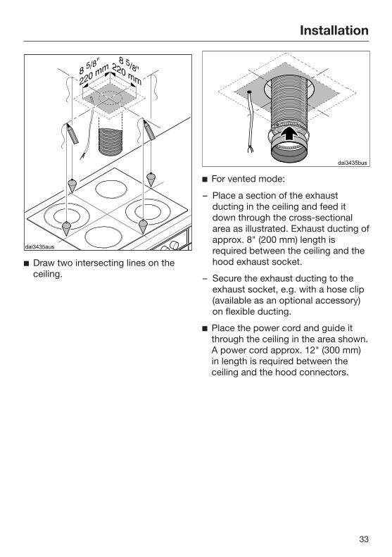
Draw two intersecting lines on theceiling.
For vented mode:
– Place a section of the exhaustducting in the ceiling and feed itdown through the cross-sectionalarea as illustrated. Exhaust ducting ofapprox. 8" (200 mm) length isrequired between the ceiling and thehood exhaust socket.
– Secure the exhaust ducting to theexhaust socket, e.g. with a hose clip(available as an optional accessory)on flexible ducting.
Place the power cord and guide itthrough the ceiling in the area shown.A power cord approx. 12" (300 mm)in length is required between theceiling and the hood connectors.

Installation
34
Use a knife to release the fourspacers and the two covers from thespacer frame supplied.
Use the spacer frame as a drillingtemplate. Place it on the ceiling withthe arrows pointing forwards. Usingthe notches, align the spacer frameon the intersecting lines and makepencil marks for the drill holes.
Drill four holes ³/₈" (10 mm),approx. 4 ¹/₂" (115 mm) deep for theplugs supplied.
Place the four plugs in the holes andscrew in the four screws so that theyprotrude by approx. 1 ³/₁₆" (30 mm).

Installation
35
Loosen the two telescopic extensionpiece holders from the installationframe.
The spacer frame can be installedbetween the chimney and the ceiling.This creates a shadow which gives theillusion of a gap between the ceiling andthe chimney. This is useful if the ceilingis not level or is uneven. The hood isaligned vertically with the spacerssupplied. Visual irregularities betweenthe chimney and the ceiling are thenconcealed by the shadow.
If you wish to install the hood with thespacer frame, remove the four insertsfrom the fixing holes.

Installation
36
Mount the spacer frame onto theinstallation frame.
Hang the hood on the four screws,making sure the controls are at thefront.
If using the spacer frame, place thetwo covers into the fixing holes.

Installation
37
Align the installation frame andsecure it with the screws.The spacers, which were removedfrom the spacer frame at the start,can be used to align the hoodvertically.
Place the exhaust ducting onto theexhaust socket.
Connect the power cord. See"Electrical connection."

Installation
38
Remove the grease filters from thehood.
Remove the safety screw for thetower on the inside of the frame.
Push the tower and the telescopicextension piece upwards and bendthe retaining tabs outwards again toprevent the tower and telescopicextension piece from slipping downagain.

Installation
39
Fit the four telescopic extensionpiece holders between the tower andthe telescopic extension piece. Theinternal telescopic extension piecerests on the clamps. When thescrews are tightened, the telescopicextension piece holders spread outand push the telescopic extensionpiece upwards.
Tighten the screws only until the topedge of the telescopic extensionpiece is evenly aligned with theceiling or the spacer frame.
When the canopy is lowered, the safetydistance to the cooker may not beexceeded (see "Appliancedimensions"). The height range for theappliance can be extended or limited bymoving the limit switch.
Press the button.
The canopy will be lowered to its fullestextent.
Check the distance to the cooker.
If the safety distance is undershot, thelimit switch must be readjusted.
Loosen the top limit switch.

Installation
40
Move the canopy to the requiredheight by pressing the button andstop it by pressing the or button.
Screw on the limit switch oppositethe guide. Hold the chimney securely, bend
back the retaining tabs and carefullylower it.
The chimney will locate in the cut-out inthe canopy.

Installation
41
1x T20 M4x16
Insert the safety screw on the inside.
Carefully remove the protective foilfrom the grease filters.
Reinsert the grease filters.

Air venting
42
WARNING: Danger of toxic fumes.Gas cooking appliances releasecarbon monoxide that can beharmful or fatal if inhaled.To reduce the risk of fire and toproperly exhaust air, the exhaustgases extracted by the hood shouldbe vented outside of the buildingonly.Do not vent exhaust air into spaceswithin walls or ceilings or in attics,crawl spaces or garages.To reduce the risk of fire, only usemetal ductwork.Please read and follow the"IMPORTANT SAFETYINSTRUCTIONS" to reduce the riskof personal injury. Follow all localbuilding codes when installing thehood.
Only use smooth pipes or flexibleduct hoses made from non-combustible materials for exhaustductwork.
To achieve the greatest possible airextraction with the lowest noise levels,please note the following:
– The diameter of the exhaust ductshould not be less than 6" (150 mm).
– If flat exhaust ducts are used, thecross section should not be smallerthan that of the exhaust connector.
– The exhaust duct should be as shortand straight as possible.
– If elbows are needed, make sure theyhave a large radius.
– The exhaust duct itself must not bekinked or compressed.
– Make sure that all connections aresecure and airtight.
Remember that any constriction ofthe airflow will reduce extractionperformance and increase operatingnoise.
If the exhaust duct is to be routedthrough an outside wall, werecommend installing a telescopicwall vent or a rooftop vent (availableas an optional accessory).
If the exhaust air is conveyed into anexhaust air chimney, the inletconnector must face the flowdirection.
When installing the exhaust ducthorizontally, a minimum slope of ¹/₈ inch per foot must be maintained toprevent condensate from flowing intothe ventilation hood.
If the exhaust duct is to be routedthrough cool rooms, ceilings, etc., thetemperatures in these different areasmay differ greatly. Therefore watercondensation must be consideredand the exhaust duct will need to beinsulated.

Air venting
43
Condensate trap
In addition to insulating the exhaustduct, we recommend installing acondensate trap to collect andevaporate any condensate which mightaccumulate.Condensate traps are available forexhaust ducts with a diameter of5" (125 mm) or 6" (150 mm).
When installing a condensate trap,make sure that it is positionedvertically and, if possible, directlyabove the hood outlet duct collar.The arrow on the housing indicatesthe direction of airflow.

Electrical connection
44
WARNING: TO REDUCE THE RISKOF FIRE, ELECTRIC SHOCK, ORINJURY TO PERSONS, OBSERVETHE FOLLOWING:All electrical work should beperformed by a qualified electricianin strict accordance with nationalregulations (for USA: ANSI-NFPA 70)and local safety regulations.Installation, repairs and other workby unqualified persons could bedangerous.Ensure that power to the appliance isOFF while installation or repair workis performed.Verify that the voltage, load andcircuit rating information found onthe data plate (located behind thebaffle filters), match the householdelectrical supply before installing thehood.Use only with ventilation hood cord-connection kits that have beeninvestigated and found acceptablefor use with this model hood.If there is any question concerningthe electrical connection of thisappliance to your power supply,please consult a licensed electricianor call Miele’s Technical ServiceDepartment.
WARNING: THIS APPLIANCE MUSTBE GROUNDED
Grounding Instructions
WARNING - Improper grounding canresult in a risk of electric shock.This appliance must be grounded. Inthe event of an electrical shortcircuit, grounding reduces the risk ofelectric shock by providing a path ofleast resistance.plug.If there is any doubt, have theelectrical system of the housechecked by a qualified electrician.
To increase security before themachine is installed, it isrecommended to install a protectiveswitch (30 mA).
The hood must be hard wiredaccordingly:Black/Red wire: connect to L1 (live)White wire: connect to N (neutral)Green wire: connect to GND (ground)
Activating Con@ctivity 2.0
45
Installation of the [email protected] stickIn order for you to be able to use theCon@ctivity 2.0 function, the cooktopmust be equipped with a [email protected] stick.
See the relevant installationinstructions of the Con@ctivity 2.0stick.
Activating the Con@ctivity 2.0functionTo use the Con@ctivity 2.0 function, theradio link between the cooktop and theventilation hood must be activated.
Both appliances must be installed andoperational.
Wireless connection must be activatedon the ventilation hood and the cooktopat the same time. Activation on theventilation hood is described below. Activation on the cooktop is describedin the relevant operating and installationinstructions. Please refer to theoperating instructions before starting.Activate the ventilation hood first, thenthe cooktop.
Activating the ventilation hood
The cooktop and ventilation hoodmust be turned off.
Press and hold the delayed shutdownbutton 515 for approx. 10 secondsuntil the 1 indicator appears in the fanlevel display.
Then, press the following buttons inorder:
– The button
– Followed by the button
– And then the lighting button .
The hood is in log on / log off mode.
If the wireless connection is activated, 2and 3 will light up at the same time. If there is no wireless connection, 2 and3 will flash constantly (Con@ctivity 2.0is already activated or a remote controlis logged on).
To activate Con@ctivity 2.0, press the"" button.
The search for a wireless connectionwill start.
As this is happening, activate thecooktop.

Activating Con@ctivity 2.0
46
Activating the cooktop
While the ventilation hood issearching for a wireless connection,start activation on the cooktop.More information can be found in theoperating instructions for thecooktop.
When the cooktop registers thatconnection has been established,confirm activation on the ventilationhood with the delayed shut-downbutton 515. All indicators will goout.
Confirm activation on the cooktop.
The Con@ctivity 2.0 function is nowready for use.
If you do not confirm within 4 minutes,activation will be canceled.
You only need to carry out theactivation procedure once. If theappliances are disconnected from theelectricity supply, for example during aloss of power, they will still remainactivated.
Activation failed
If a wireless connection cannot beestablished despite activation of theCon@ctivity function on theventilation hood and cooktop, thefunction must first be deactivated andthen reactivated on both appliances.
Deactivating Con@ctivity 2.0 Deactivation on the ventilation hood
is carried out in the same way asactivation, by selecting instead of.
To deactivate the burner, please referto the corresponding operatinginstructions.
Please keep in mind that disabling theconnection will also disable anyremote control function being used.The remote control must then bereactivated.

Service and warranty
47
For faults that you cannot resolve onyour own, please contact your Mieledealer or Miele Technical Service.
The telephone number for Miele is listedat the back of these instructions.
When contacting Miele, please state themodel and serial number of yourventilation hood.These can be found on the data plate.
Location of the data plateThe data plate is visible once you haveremoved the grease filters.
WarrantyFor further information, please refer toyour warranty booklet.

Technical data
48
Fan motor 350 W
Height adjustment motor 150 W
LED cooktop lighting 4 x 3 W
Total connected load 512 W
Voltage, frequency 120 V AC, 60 Hz
Fuse rating 15 A
Weight 107.8 lbs (49 kg)
ContainsFCC ID: 2ACUWEI8800IC: 5669C-EI8800
This device complies with Part 15 of the FCC Rules and with Industry Canadalicence-exempt RSS standard(s). Operation is subject to the following twoconditions: (1) this device may not cause harmful interference, and (2) this devicemust accept any interference received, including interference that may causeundesired operation.


9 Independence WayPrinceton, NJ 08540Phone:Fax:www.mieleusa.com
U.S.A.Miele, Inc.
National Headquarters
Please have the model and serial numberof your appliance available whencontacting Technical Service.
CanadaImporterMiele Limited
Headquarters and Miele Centre
800-843-7231609-419-4298
Technical Service & SupportPhone:Fax:[email protected]
161 Four Valley DriveVaughan, ON L4K 4V8www.miele.ca
800-999-1360888-586-8056
Customer Care CentrePhone:
800-565-6435905-532-2272
International HeadquartersMiele & Cie. KGCarl-Miele-Straße 2933332 GüterslohGermany

M.-Nr. 10 118 580 / 03en-US
DA 424V-6