OPERA T ING MANUAL SQM-160
144
O P E R A T I N G M A N U A L SQM-160 ™ Multi-Film Rate/Thickness Monitor PN 074-511-P1E Cover Page
Transcript of OPERA T ING MANUAL SQM-160

O P E R A T I N G M A N U A L
SQM-160™
Multi-Film Rate/Thickness MonitorPN 074-511-P1E
Cover Page


www.inficon.com [email protected]©2015 INFICON
®
O P E R A T I N G M A N U A L
PN 074-511-P1E
Title Page
SQM-160™
Multi-Film Rate/Thickness Monitor

Trademarks
The trademarks of the products mentioned in this manual are held by the companies that produce them.
INFICON® is a trademark of INFICON Inc.
SQM-160™ and INFICON® are trademarks of INFICON GmbH.
Visual Basic®, Windows®, and Excel® are registered trademarks of Microsoft Corporation.
Java® is a registered trademarks of Oracle and/or its affiliates.
Inconel® is a registered trademark of Inco Alloys International, Huntington, WV.
All other brand and product names are trademarks or registered trademarks of their respective companies.
Disclaimer
The information contained in this manual is believed to be accurate and reliable. However, INFICON assumes no responsibility for its use and shall not be liable for any special, incidental, or consequential damages related to the use of this product.
Due to our continuing program of product improvements, specifications are subject to change without notice.
Copyright
©2015 All rights reserved. Reproduction or adaptation of any part of this document without permission is unlawful.


WARRANTY AND LIABILITY - LIMITATION: Seller warrants the products manufactured by it, or by an affiliated company and sold by it, and described on the reverse hereof, to be, for the period of warranty coverage specified below, free from defects of materials or workmanship under normal proper use and service. The period of warranty coverage is specified for the respective products in the respective Seller instruction manuals for those products but shall not be less than two (2) years from the date of shipment thereof by Seller. Seller's liability under this warranty is limited to such of the above products or parts thereof as are returned, transportation prepaid, to Seller's plant, not later than thirty (30) days after the expiration of the period of warranty coverage in respect thereof and are found by Seller's examination to have failed to function properly because of defective workmanship or materials and not because of improper installation or misuse and is limited to, at Seller's election, either (a) repairing and returning the product or part thereof, or (b) furnishing a replacement product or part thereof, transportation prepaid by Seller in either case. In the event Buyer discovers or learns that a product does not conform to warranty, Buyer shall immediately notify Seller in writing of such non-conformity, specifying in reasonable detail the nature of such non-conformity. If Seller is not provided with such written notification, Seller shall not be liable for any further damages which could have been avoided if Seller had been provided with immediate written notification.
THIS WARRANTY IS MADE AND ACCEPTED IN LIEU OF ALL OTHER WARRANTIES, EXPRESS OR IMPLIED, WHETHER OF MERCHANTABILITY OR OF FITNESS FOR A PARTICULAR PURPOSE OR OTHERWISE, AS BUYER'S EXCLUSIVE REMEDY FOR ANY DEFECTS IN THE PRODUCTS TO BE SOLD HEREUNDER. All other obligations and liabilities of Seller, whether in contract or tort (including negligence) or otherwise, are expressly EXCLUDED. In no event shall Seller be liable for any costs, expenses or damages, whether direct or indirect, special, incidental, consequential, or other, on any claim of any defective product, in excess of the price paid by Buyer for the product plus return transportation charges prepaid.
No warranty is made by Seller of any Seller product which has been installed, used or operated contrary to Seller's written instruction manual or which has been subjected to misuse, negligence or accident or has been repaired or altered by anyone other than Seller or which has been used in a manner or for a purpose for which the Seller product was not designed nor against any defects due to plans or instructions supplied to Seller by or for Buyer.
This manual is intended for private use by INFICON® Inc. and its customers. Contact INFICON before reproducing its contents.
NOTE: These instructions do not provide for every contingency that may arise in connection with the installation, operation or maintenance of this equipment. Should you require further assistance, please contact INFICON.
Warranty
www.inficon.com [email protected]


PN
074
-511
-P1E
SQM-160 Operating Manual
Table Of Contents
Cover Page
Title Page
Trademarks
Disclaimer
Copyright
Declaration Of Conformity
Warranty
Chapter 1Introduction and Specifications
1.1 Introduction. . . . . . . . . . . . . . . . . . . . . . . . . . . . . . . . . . . . . . . . . . . . . . . . . . 1-1
1.1.1 Related Manuals. . . . . . . . . . . . . . . . . . . . . . . . . . . . . . . . . . . . . . . . . . . . . . 1-2
1.2 Instrument Safety . . . . . . . . . . . . . . . . . . . . . . . . . . . . . . . . . . . . . . . . . . . . . 1-2
1.2.1 Definition of Notes, Cautions, and Warnings . . . . . . . . . . . . . . . . . . . . . . . . 1-2
1.2.2 General Safety Information. . . . . . . . . . . . . . . . . . . . . . . . . . . . . . . . . . . . . . 1-3
1.2.3 Earth Ground . . . . . . . . . . . . . . . . . . . . . . . . . . . . . . . . . . . . . . . . . . . . . . . . 1-4
1.3 How To Contact INFICON . . . . . . . . . . . . . . . . . . . . . . . . . . . . . . . . . . . . . . 1-4
1.3.1 Returning SQM-160 . . . . . . . . . . . . . . . . . . . . . . . . . . . . . . . . . . . . . . . . . . . 1-5
1.4 Specifications . . . . . . . . . . . . . . . . . . . . . . . . . . . . . . . . . . . . . . . . . . . . . . . . 1-5
1.4.1 Measurement . . . . . . . . . . . . . . . . . . . . . . . . . . . . . . . . . . . . . . . . . . . . . . . . 1-5
1.4.2 Film Parameters . . . . . . . . . . . . . . . . . . . . . . . . . . . . . . . . . . . . . . . . . . . . . . 1-6
1.4.3 System Parameters . . . . . . . . . . . . . . . . . . . . . . . . . . . . . . . . . . . . . . . . . . . 1-6
1.4.4 Digital I/O . . . . . . . . . . . . . . . . . . . . . . . . . . . . . . . . . . . . . . . . . . . . . . . . . . . 1-7
1.4.5 General Specifications . . . . . . . . . . . . . . . . . . . . . . . . . . . . . . . . . . . . . . . . . 1-7
1.5 Unpacking and Inspection . . . . . . . . . . . . . . . . . . . . . . . . . . . . . . . . . . . . . . 1-8
1.6 Configurations and Accessories . . . . . . . . . . . . . . . . . . . . . . . . . . . . . . . . . . 1-8
1.6.1 SQM-160 Configurations . . . . . . . . . . . . . . . . . . . . . . . . . . . . . . . . . . . . . . . 1-8
1.6.2 Accessories . . . . . . . . . . . . . . . . . . . . . . . . . . . . . . . . . . . . . . . . . . . . . . . . . 1-9
1.6.2.1 Oscillator Kits . . . . . . . . . . . . . . . . . . . . . . . . . . . . . . . . . . . . . . . . . . . . . . . . 1-9
1.6.2.2 Rack Mounting Options . . . . . . . . . . . . . . . . . . . . . . . . . . . . . . . . . . . . . . . . 1-9
1.6.2.3 Sensors . . . . . . . . . . . . . . . . . . . . . . . . . . . . . . . . . . . . . . . . . . . . . . . . . . . 1-10
Chapter 2Installation
2.1 Installation Requirements . . . . . . . . . . . . . . . . . . . . . . . . . . . . . . . . . . . . . . . 2-1
2.1.1 Parts Requirements . . . . . . . . . . . . . . . . . . . . . . . . . . . . . . . . . . . . . . . . . . . 2-1
TOC - 1

PN
074
-511
-P1E
SQM-160 Operating Manual
2.1.2 Ground Requirements . . . . . . . . . . . . . . . . . . . . . . . . . . . . . . . . . . . . . . . . . 2-2
2.1.3 Establishing Earth Ground . . . . . . . . . . . . . . . . . . . . . . . . . . . . . . . . . . . . . . 2-3
2.2 Rack Mounting Procedure . . . . . . . . . . . . . . . . . . . . . . . . . . . . . . . . . . . . . . 2-3
2.2.1 Full Rack Extender . . . . . . . . . . . . . . . . . . . . . . . . . . . . . . . . . . . . . . . . . . . . 2-3
2.2.1.1 Inventory. . . . . . . . . . . . . . . . . . . . . . . . . . . . . . . . . . . . . . . . . . . . . . . . . . . . 2-3
2.2.1.2 Installation . . . . . . . . . . . . . . . . . . . . . . . . . . . . . . . . . . . . . . . . . . . . . . . . . . 2-4
2.2.2 Rack Adapter . . . . . . . . . . . . . . . . . . . . . . . . . . . . . . . . . . . . . . . . . . . . . . . . 2-8
2.2.2.1 Inventory. . . . . . . . . . . . . . . . . . . . . . . . . . . . . . . . . . . . . . . . . . . . . . . . . . . . 2-8
2.2.2.2 Installation . . . . . . . . . . . . . . . . . . . . . . . . . . . . . . . . . . . . . . . . . . . . . . . . . . 2-8
2.3 Rear Panel Interfaces. . . . . . . . . . . . . . . . . . . . . . . . . . . . . . . . . . . . . . . . . 2-11
2.4 System Connections . . . . . . . . . . . . . . . . . . . . . . . . . . . . . . . . . . . . . . . . . 2-12
2.4.1 Sensor Connections . . . . . . . . . . . . . . . . . . . . . . . . . . . . . . . . . . . . . . . . . . 2-13
2.5 I/O Connections . . . . . . . . . . . . . . . . . . . . . . . . . . . . . . . . . . . . . . . . . . . . . 2-14
Chapter 3Operation
3.1 Introduction. . . . . . . . . . . . . . . . . . . . . . . . . . . . . . . . . . . . . . . . . . . . . . . . . . 3-1
3.2 Front Panel Controls . . . . . . . . . . . . . . . . . . . . . . . . . . . . . . . . . . . . . . . . . . 3-1
3.3 Menu Selection. . . . . . . . . . . . . . . . . . . . . . . . . . . . . . . . . . . . . . . . . . . . . . . 3-3
3.4 Film Menu. . . . . . . . . . . . . . . . . . . . . . . . . . . . . . . . . . . . . . . . . . . . . . . . . . . 3-4
3.5 System Menu . . . . . . . . . . . . . . . . . . . . . . . . . . . . . . . . . . . . . . . . . . . . . . . . 3-6
3.6 Sensor Selection . . . . . . . . . . . . . . . . . . . . . . . . . . . . . . . . . . . . . . . . . . . . . 3-9
3.7 Sensor Frequency . . . . . . . . . . . . . . . . . . . . . . . . . . . . . . . . . . . . . . . . . . . 3-10
3.8 Sensor Tooling . . . . . . . . . . . . . . . . . . . . . . . . . . . . . . . . . . . . . . . . . . . . . . 3-11
3.9 Display Units . . . . . . . . . . . . . . . . . . . . . . . . . . . . . . . . . . . . . . . . . . . . . . . 3-12
3.10 Crystal Life . . . . . . . . . . . . . . . . . . . . . . . . . . . . . . . . . . . . . . . . . . . . . . . . . 3-12
3.11 Zero Thickness. . . . . . . . . . . . . . . . . . . . . . . . . . . . . . . . . . . . . . . . . . . . . . 3-13
3.12 Shutter Operation . . . . . . . . . . . . . . . . . . . . . . . . . . . . . . . . . . . . . . . . . . . . 3-13
3.13 Dual Sensors . . . . . . . . . . . . . . . . . . . . . . . . . . . . . . . . . . . . . . . . . . . . . . . 3-13
3.14 Rate Sampling . . . . . . . . . . . . . . . . . . . . . . . . . . . . . . . . . . . . . . . . . . . . . . 3-14
3.15 Time Setpoint . . . . . . . . . . . . . . . . . . . . . . . . . . . . . . . . . . . . . . . . . . . . . . . 3-15
3.16 Thickness Setpoint . . . . . . . . . . . . . . . . . . . . . . . . . . . . . . . . . . . . . . . . . . . 3-16
3.17 Simulate Mode . . . . . . . . . . . . . . . . . . . . . . . . . . . . . . . . . . . . . . . . . . . . . . 3-17
3.18 Defaulting the Memory . . . . . . . . . . . . . . . . . . . . . . . . . . . . . . . . . . . . . . . . 3-17
3.19 Relay Operation . . . . . . . . . . . . . . . . . . . . . . . . . . . . . . . . . . . . . . . . . . . . . 3-18
3.20 Analog Output Configuration . . . . . . . . . . . . . . . . . . . . . . . . . . . . . . . . . . . 3-18
3.21 Depositing a Film . . . . . . . . . . . . . . . . . . . . . . . . . . . . . . . . . . . . . . . . . . . . 3-19
TOC - 2

PN
074
-511
-P1E
SQM-160 Operating Manual
Chapter 4SQM-160 Comm Software
4.1 Introduction. . . . . . . . . . . . . . . . . . . . . . . . . . . . . . . . . . . . . . . . . . . . . . . . . . 4-1
4.2 Installation . . . . . . . . . . . . . . . . . . . . . . . . . . . . . . . . . . . . . . . . . . . . . . . . . . 4-1
4.2.1 Update of an Older Version of SQM-160 Comm . . . . . . . . . . . . . . . . . . . . . 4-2
4.3 Start the SQM-160 V2 Comm software. . . . . . . . . . . . . . . . . . . . . . . . . . . . . 4-3
4.4 Main Window . . . . . . . . . . . . . . . . . . . . . . . . . . . . . . . . . . . . . . . . . . . . . . . . 4-4
4.4.1 Menu Bar Functions . . . . . . . . . . . . . . . . . . . . . . . . . . . . . . . . . . . . . . . . . . . 4-5
4.4.1.1 File Menu . . . . . . . . . . . . . . . . . . . . . . . . . . . . . . . . . . . . . . . . . . . . . . . . . . . 4-6
4.4.1.2 Edit Menu . . . . . . . . . . . . . . . . . . . . . . . . . . . . . . . . . . . . . . . . . . . . . . . . . . . 4-7
4.4.1.3 View Menu . . . . . . . . . . . . . . . . . . . . . . . . . . . . . . . . . . . . . . . . . . . . . . . . . . 4-7
4.4.1.4 Help Menu . . . . . . . . . . . . . . . . . . . . . . . . . . . . . . . . . . . . . . . . . . . . . . . . . . 4-7
4.4.2 Main Window Control Functions. . . . . . . . . . . . . . . . . . . . . . . . . . . . . . . . . . 4-8
4.5 Data Log Window . . . . . . . . . . . . . . . . . . . . . . . . . . . . . . . . . . . . . . . . . . . . . 4-9
4.5.1 Log File Pane . . . . . . . . . . . . . . . . . . . . . . . . . . . . . . . . . . . . . . . . . . . . . . . 4-10
4.5.2 Duration Pane. . . . . . . . . . . . . . . . . . . . . . . . . . . . . . . . . . . . . . . . . . . . . . . 4-11
4.5.3 Time Range Pane. . . . . . . . . . . . . . . . . . . . . . . . . . . . . . . . . . . . . . . . . . . . 4-11
4.5.4 Sampling Interval Pane . . . . . . . . . . . . . . . . . . . . . . . . . . . . . . . . . . . . . . . 4-11
4.6 Films Window . . . . . . . . . . . . . . . . . . . . . . . . . . . . . . . . . . . . . . . . . . . . . . . 4-11
4.7 System Parameters Window . . . . . . . . . . . . . . . . . . . . . . . . . . . . . . . . . . . 4-15
4.8 Communications Setup Window. . . . . . . . . . . . . . . . . . . . . . . . . . . . . . . . . 4-17
4.8.1 Establishing Communications . . . . . . . . . . . . . . . . . . . . . . . . . . . . . . . . . . 4-18
4.8.2 Command Field . . . . . . . . . . . . . . . . . . . . . . . . . . . . . . . . . . . . . . . . . . . . . 4-20
4.9 Configure Graph(s) Window. . . . . . . . . . . . . . . . . . . . . . . . . . . . . . . . . . . . 4-21
4.10 Help Menu . . . . . . . . . . . . . . . . . . . . . . . . . . . . . . . . . . . . . . . . . . . . . . . . . 4-23
Chapter 5Communications
5.1 Introduction. . . . . . . . . . . . . . . . . . . . . . . . . . . . . . . . . . . . . . . . . . . . . . . . . . 5-1
5.1.1 RS-232 Serial Port . . . . . . . . . . . . . . . . . . . . . . . . . . . . . . . . . . . . . . . . . . . . 5-1
5.1.2 USB Port. . . . . . . . . . . . . . . . . . . . . . . . . . . . . . . . . . . . . . . . . . . . . . . . . . . . 5-2
5.1.3 Ethernet Port . . . . . . . . . . . . . . . . . . . . . . . . . . . . . . . . . . . . . . . . . . . . . . . . 5-2
5.1.3.1 How to Set Up the Network Protocol on the Computer . . . . . . . . . . . . . . . . 5-2
5.1.3.1.1 Accessing Network Settings in Windows XP . . . . . . . . . . . . . . . . . . . . . . . . 5-3
5.1.3.1.2 Accessing Network Settings in Windows 7 and Windows 8 . . . . . . . . . . . . . 5-6
5.1.3.2 How to change the SQM-160 IP address . . . . . . . . . . . . . . . . . . . . . . . . . . . 5-8
5.2 SQM-160 Comm Software . . . . . . . . . . . . . . . . . . . . . . . . . . . . . . . . . . . . . . 5-9
5.3 SQM-160 Communications Protocol . . . . . . . . . . . . . . . . . . . . . . . . . . . . . . 5-9
5.3.1 Command Packet (Host to SQM-160 Message) . . . . . . . . . . . . . . . . . . . . . 5-9
5.3.2 Response Packet (SQM-160 to Host Message). . . . . . . . . . . . . . . . . . . . . 5-10
TOC - 3

PN
074
-511
-P1E
SQM-160 Operating Manual
5.3.3 Calculating the CRC. . . . . . . . . . . . . . . . . . . . . . . . . . . . . . . . . . . . . . . . . . 5-11
5.4 Commands . . . . . . . . . . . . . . . . . . . . . . . . . . . . . . . . . . . . . . . . . . . . . . . . . 5-12
5.4.1 Command: @ . . . . . . . . . . . . . . . . . . . . . . . . . . . . . . . . . . . . . . . . . . . . . . . 5-13
5.4.2 Command: A . . . . . . . . . . . . . . . . . . . . . . . . . . . . . . . . . . . . . . . . . . . . . . . 5-13
5.4.3 Command: B . . . . . . . . . . . . . . . . . . . . . . . . . . . . . . . . . . . . . . . . . . . . . . . 5-15
5.4.4 Command: C . . . . . . . . . . . . . . . . . . . . . . . . . . . . . . . . . . . . . . . . . . . . . . . 5-16
5.4.5 Command: D . . . . . . . . . . . . . . . . . . . . . . . . . . . . . . . . . . . . . . . . . . . . . . . 5-17
5.4.6 Command: J . . . . . . . . . . . . . . . . . . . . . . . . . . . . . . . . . . . . . . . . . . . . . . . . 5-17
5.4.7 Command: L. . . . . . . . . . . . . . . . . . . . . . . . . . . . . . . . . . . . . . . . . . . . . . . . 5-17
5.4.8 Command: M . . . . . . . . . . . . . . . . . . . . . . . . . . . . . . . . . . . . . . . . . . . . . . . 5-18
5.4.9 Command: N . . . . . . . . . . . . . . . . . . . . . . . . . . . . . . . . . . . . . . . . . . . . . . . 5-18
5.4.10 Command: O . . . . . . . . . . . . . . . . . . . . . . . . . . . . . . . . . . . . . . . . . . . . . . . 5-18
5.4.11 Command: P . . . . . . . . . . . . . . . . . . . . . . . . . . . . . . . . . . . . . . . . . . . . . . . 5-19
5.4.12 Command: R . . . . . . . . . . . . . . . . . . . . . . . . . . . . . . . . . . . . . . . . . . . . . . . 5-19
5.4.13 Command: S . . . . . . . . . . . . . . . . . . . . . . . . . . . . . . . . . . . . . . . . . . . . . . . 5-19
5.4.14 Command: T. . . . . . . . . . . . . . . . . . . . . . . . . . . . . . . . . . . . . . . . . . . . . . . . 5-20
5.4.15 Command: U . . . . . . . . . . . . . . . . . . . . . . . . . . . . . . . . . . . . . . . . . . . . . . . 5-20
5.4.16 Command: W . . . . . . . . . . . . . . . . . . . . . . . . . . . . . . . . . . . . . . . . . . . . . . . 5-20
5.4.17 Command: Y . . . . . . . . . . . . . . . . . . . . . . . . . . . . . . . . . . . . . . . . . . . . . . . 5-21
5.4.18 Command: Z. . . . . . . . . . . . . . . . . . . . . . . . . . . . . . . . . . . . . . . . . . . . . . . . 5-21
5.5 CRC Examples. . . . . . . . . . . . . . . . . . . . . . . . . . . . . . . . . . . . . . . . . . . . . . 5-22
5.5.1 Visual Basic® 5/6 . . . . . . . . . . . . . . . . . . . . . . . . . . . . . . . . . . . . . . . . . . . . 5-22
5.5.2 Java® . . . . . . . . . . . . . . . . . . . . . . . . . . . . . . . . . . . . . . . . . . . . . . . . . . . . . 5-24
5.5.3 C++. . . . . . . . . . . . . . . . . . . . . . . . . . . . . . . . . . . . . . . . . . . . . . . . . . . . . . . 5-25
Chapter 6 Troubleshooting and Maintenance
6.1 Troubleshooting Guide . . . . . . . . . . . . . . . . . . . . . . . . . . . . . . . . . . . . . . . . . 6-1
6.2 Maintenance. . . . . . . . . . . . . . . . . . . . . . . . . . . . . . . . . . . . . . . . . . . . . . . . 6-12
6.3 Spare Parts . . . . . . . . . . . . . . . . . . . . . . . . . . . . . . . . . . . . . . . . . . . . . . . . 6-12
6.4 Persistent Crystal Fail Indication . . . . . . . . . . . . . . . . . . . . . . . . . . . . . . . . 6-13
Chapter 7Calibration Procedures
7.1 Importance of Density, Tooling and Z-Ratio. . . . . . . . . . . . . . . . . . . . . . . . . 7-1
7.2 Determining Density . . . . . . . . . . . . . . . . . . . . . . . . . . . . . . . . . . . . . . . . . . . 7-1
7.3 Determining Tooling . . . . . . . . . . . . . . . . . . . . . . . . . . . . . . . . . . . . . . . . . . . 7-2
7.4 Laboratory Determination of Z-Ratio . . . . . . . . . . . . . . . . . . . . . . . . . . . . . . 7-3
TOC - 4
PN
074
-511
-P1E
SQM-160 Operating Manual
Chapter 8Measurement and Theory
8.1 Basics . . . . . . . . . . . . . . . . . . . . . . . . . . . . . . . . . . . . . . . . . . . . . . . . . . . . . . 8-1
8.1.1 Monitor Crystals . . . . . . . . . . . . . . . . . . . . . . . . . . . . . . . . . . . . . . . . . . . . . . 8-2
8.1.2 Period Measurement Technique . . . . . . . . . . . . . . . . . . . . . . . . . . . . . . . . . 8-4
8.1.3 Z-match Technique. . . . . . . . . . . . . . . . . . . . . . . . . . . . . . . . . . . . . . . . . . . . 8-6
Appendix AMaterial Table
A.1 Introduction. . . . . . . . . . . . . . . . . . . . . . . . . . . . . . . . . . . . . . . . . . . . . . . . . .A-1
TOC - 5

PN
074
-511
-P1E
SQM-160 Operating Manual
This page is intentionally blank.
TOC - 6

PN
074
-511
-P1E
SQM-160 Operating Manual
Chapter 1Introduction and Specifications
1.1 Introduction
Figure 1-1 SQM-160 multi-film rate/thickness monitor
SQM-160™ uses proven INFICON® quartz crystal sensor technology to measure rate and thickness in a thin film deposition process. Two sensor inputs are standard and four additional sensor inputs are optional. Two recorder outputs provide both analog rate and thickness signals.
Sensor inputs are assigned to different materials, averaged for accurate deposition control in large systems or configured for a dual sensor. The rate sampling mode allows a shuttered sensor to extend sensor life in high rate processes. Rate displays of 0.1 Å/s or 0.01 Å/s are user-selectable. In addition, frequency or mass displays can be selected. Four relay outputs allow SQM-160 to control source or sensor shutters, signal time and thickness setpoints, and signal crystal failure. Digital inputs allow external signals to start/stop and zero readings.
SQM-160 comes with an RS-232 port and Windows® software that allows instrument setup from a computer. The software can be used to set and store all parameters, operate SQM-160, and save process data in a .txt file that can be imported into Excel®. Universal Serial Bus (USB) or Ethernet options add to the communications flexibility.
1 - 1
PN
074
-511
-P1E
SQM-160 Operating Manual
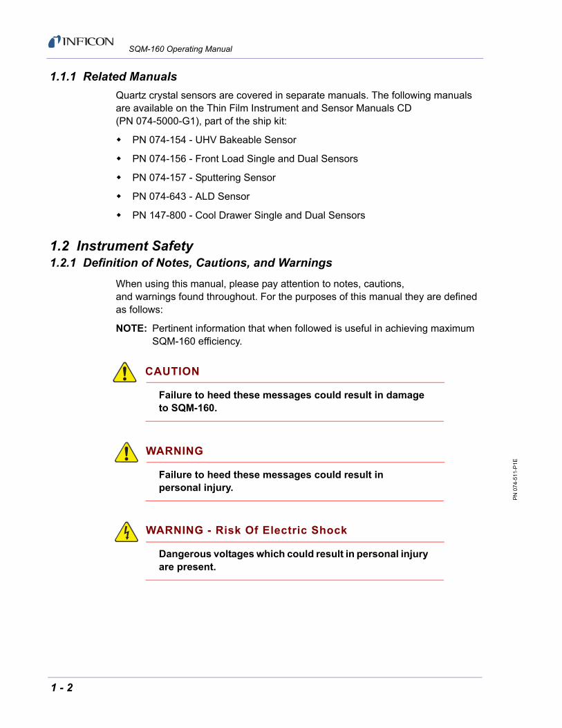
1.1.1 Related Manuals
Quartz crystal sensors are covered in separate manuals. The following manuals are available on the Thin Film Instrument and Sensor Manuals CD (PN 074-5000-G1), part of the ship kit:
PN 074-154 - UHV Bakeable Sensor
PN 074-156 - Front Load Single and Dual Sensors
PN 074-157 - Sputtering Sensor
PN 074-643 - ALD Sensor
PN 147-800 - Cool Drawer Single and Dual Sensors
1.2 Instrument Safety1.2.1 Definition of Notes, Cautions, and Warnings
When using this manual, please pay attention to notes, cautions, and warnings found throughout. For the purposes of this manual they are defined as follows:
NOTE: Pertinent information that when followed is useful in achieving maximum SQM-160 efficiency.
CAUTION
Failure to heed these messages could result in damage to SQM-160.
WARNING
Failure to heed these messages could result in personal injury.
WARNING - Risk Of Electric Shock
Dangerous voltages which could result in personal injury are present.
1 - 2

PN
074
-511
-P1E
SQM-160 Operating Manual
1.2.2 General Safety Information
WARNING
Do not open the SQM-160 case. Refer all maintenance to qualified personnel.
There are no user-serviceable components within the SQM-160 case. Dangerous voltages may be present whenever the power cable or external input/relay connectors are present.
WARNING
SQM-160 contains delicate circuitry, susceptible to transient power line voltages. Disconnect the power cable whenever making any interface connections.
Refer all maintenance to qualified personnel.
1 - 3

PN
074
-511
-P1E
SQM-160 Operating Manual
1.2.3 Earth Ground
SQM-160 is connected to earth ground through a sealed three-core (three-conductor) power cable, which must be plugged into a socket outlet with a protective earth terminal. Extension cables must always have three conductors including a protective earth terminal.
WARNING
Never interrupt the protective earth circuit.
This symbol indicates where the protective earth ground is connected inside SQM-160.
Never unscrew or loosen this connection.
Disconnecting the protective earth terminal or interrupting the protective earth circuit, whether inside or outside of SQM-160, may render SQM-160 dangerous.
1.3 How To Contact INFICONWorldwide customer support information is available under Support >> Support Worldwide at www.inficon.com.
Sales and Customer Service
Technical Support
Repair Service
When experiencing a problem with SQM-160, please have the following information readily available:
The Sales Order or Purchase Order number of the SQM-160 purchase
The version of SQM-160 firmware
The version of Windows operating system
A description of the problem
An explanation of any corrective action that may have already been attempted
The exact wording of any error messages that may have been received
1 - 4

PN
074
-511
-P1E
SQM-160 Operating Manual
1.3.1 Returning SQM-160
Do not return any component of SQM-160 to INFICON before speaking with a Customer Support Representative and obtaining a Return Material Authorization (RMA) number. SQM-160 will not be serviced without an RMA number.
Packages delivered to INFICON without an RMA number will be held until the customer is contacted. This will result in delays in servicing SQM-160.
If returning SQM-160 with a crystal sensor or another component potentially exposed to process materials, prior to being given an RMA number, a completed Declaration Of Contamination (DOC) form will be required. DOC forms must be approved by INFICON before an RMA number is issued. INFICON may require that the component be sent to a designated decontamination facility, not to the factory.
1.4 Specifications1.4.1 Measurement
Sensor Inputs . . . . . . . . . . . . . . . . . . Two standard, Four additional (optional)
Measurement Frequency Range . . . 6.5 to 1.0 MHz (adjustable)
Reference Frequency Accuracy . . . . 0.002%
Reference Frequency Stability . . . . . ±2 ppm (total, 0 to 50°C)
Thickness Display Resolution . . . . . 1 Å
Frequency Resolution1. . . . . . . . . . . Standard: ±0.30 Hz @ 6 MHz High Resolution option: ±0.03 Hz @ 6 MHz
Thickness and RateResolution/Measurement2 . . . . . . . . Standard: ±0.37 Å
High Resolution option: ±0.037 Å
Measurement Interval. . . . . . . . . . . . 0.10 to 2.0 s (adjustable)
1Resolution given for 0.10 s measurement interval
2Tooling/Density = 100/1, fundamental frequency = 6 MHz, 0.10 s measurement interval
1 - 5

PN
074
-511
-P1E
SQM-160 Operating Manual
1.4.2 Film Parameters
Stored Films . . . . . . . . . . . . . . . . . . . 99
Density . . . . . . . . . . . . . . . . . . . . . . . 0.50 to 99.99 g/cm3
Tooling . . . . . . . . . . . . . . . . . . . . . . . 10 to 399%
Z-Ratio . . . . . . . . . . . . . . . . . . . . . . . 0.10 to 10.00
Final Thickness . . . . . . . . . . . . . . . . 0.000 to 9999 kÅ
Thickness Setpoint . . . . . . . . . . . . . . 0.000 to 9999 kÅ
Time Setpoint . . . . . . . . . . . . . . . . . . 0:00 to 99:59 mm:ss
Sample/Hold. . . . . . . . . . . . . . . . . . . 0 to 5999 s
Sensor Average . . . . . . . . . . . . . . . . 1 to 6, depending on sensors installed
1.4.3 System Parameters
Measurement Period . . . . . . . . . . . . 0.10 to 2.00 s
Simulate Mode . . . . . . . . . . . . . . . . . On/Off
Display Mode . . . . . . . . . . . . . . . . . . Thickness in kÅ (THCK)Thickness in µm (NANM)Frequency in Hz (FREQ)Mass in µg/cm2 (MASS)
Rate Resolution . . . . . . . . . . . . . . . . 0.01 Å/s (HI)0.1 Å/s (LO)
Measurement Filter . . . . . . . . . . . . . 1 to 20 readings
Relay 2 Mode . . . . . . . . . . . . . . . . . . Time Setpoint (TIME)Dual Sensor Shutter (DUAL)Sensor 2 Shutter (SNS2)
Relay (1 to 4) . . . . . . . . . . . . . . . . . . Normally Open (nO)/Normally Closed (nC)
Rate Sampling . . . . . . . . . . . . . . . . . On/Off
RS-232 Baud Rate . . . . . . . . . . . . . . 2.4, 4.8, 9.6, 19.2, 38.4, 57.6, 115.2 kbps
Etch Mode . . . . . . . . . . . . . . . . . . . . On/Off
Crystal Tooling (1 to 6) . . . . . . . . . . . 10 to 399%
Frequency Min/Max . . . . . . . . . . . . . 1.0 to 6.4 MHz/1.1 to 6.5 MHz
Analog Output Bounds
Rate Min/Max . . . . . . . . . . . . . . . -99 to 999 Å/s
Thickness Min/Max. . . . . . . . . . . 0.0 to -9999 kÅ
1 - 6

PN
074
-511
-P1E
SQM-160 Operating Manual
1.4.4 Digital I/O
Digital Inputs. . . . . . . . . . . . . . . . . . . 4
Functions . . . . . . . . . . . . . . . . . . . . . Open Shutter, Close Shutter, Zero Thickness, Zero Time
Input Rating . . . . . . . . . . . . . . . . . . . 5 V (dc), non-isolated
Relay Outputs. . . . . . . . . . . . . . . . . . 4
Functions . . . . . . . . . . . . . . . . . . . . . Shutter, Sample/Hold or Thickness Setpoint, Dual Sensor Shutter or Time Setpoint, Crystal Fail
Relay Rating. . . . . . . . . . . . . . . . . . . 30 V (rms) or 30 V (dc), 2 A maximum
1.4.5 General Specifications
Mains Power Supply. . . . . . . . . . . . . 100 to 240 V (ac), ±10% nominal, 50/60 Hz
Fuse . . . . . . . . . . . . . . . . . . . . . . . . . 5 x 20 mm, 500 mA, 250 V time lag
Power Consumption . . . . . . . . . . . . . 20 W
Temporary Overvoltages . . . . . . . . . Short Term: 1440 V, <5 sLong Term: 490 V, >5 s
Operating Environment . . . . . . . . . . 0 to 50°C (32 to 122°F)0 to 80% RH non-condensing0 to 2000 mIndoor Use OnlyClass 1 Equipment (Grounded Type)Suitable for Continuous OperationOrdinary Protection (not protected against harmful ingress of moisture)Pollution Degree 2Installation (Overvoltage) Category IIfor transient overvoltages
Storage Environment . . . . . . . . . . . . -10 to 60°C (14 to 140°F)
Rack Dimensions (HxWxD) . . . . . . . 8.85 x 21.26 x 19.68 cm (3.48 x 8.37 x 7.75 in.)
Weight . . . . . . . . . . . . . . . . . . . . . . . 2.7 kg (6 lb.)
1 - 7

PN
074
-511
-P1E
SQM-160 Operating Manual
1.5 Unpacking and Inspection
1 Remove SQM-160 from its packaging.
2 Carefully examine SQM-160 for damage that may have occurred during shipping. It is especially important to note obvious rough handling on the exterior of the container. Immediately report any damage to the carrier as well as to INFICON.
3 Turn ON SQM-160.
4 Refer to the invoice and take inventory (see section 1.6). Do not discard the packing materials before verifying inventory and power.
5 To install and set up, see Chapter 2, Installation.
6 For additional information or technical assistance, contact INFICON (refer to section 1.3 on page 1-4).
1.6 Configurations and Accessories1.6.1 SQM-160 Configurations
SQM-160 . . . . . . . . . . . . . . . . . . . . . . . . .SQM160-X-X-X
Consult the figure below for possible configurations.
Figure 1-2 SQM-160 configurations
NOTE: All configurations ship with Thin Film Instrument and Sensor Manuals CD (PN 074-5000-G1), which contains the SQM-160 Operating Manual (PN 074-511), SQM-160 Comm software, and sensor manuals.
1 - 8

PN
074
-511
-P1E
SQM-160 Operating Manual
1.6.2 Accessories
1.6.2.1 Oscillator Kits
Each sensor requires an oscillator kit to interface with the controller:
3 m (10 ft.) Oscillator Kit . . . . . . . . . . . . . PN 783-500-109-10
7.6 m (25 ft.) Oscillator Kit . . . . . . . . . . . PN 783-500-109-25
15.2 m (50 ft.) Oscillator Kit . . . . . . . . . . PN 783-500-109-50
22.8 m (75 ft.) Oscillator Kit . . . . . . . . . . PN 783-500-109-75
Each oscillator kit includes:
Oscillator, PN 783-500-013
15.2 cm (6 in.) BNC cable, PN 782-902-011
One of the following BNC cables:
3 m (10 ft.) BNC Cable . . . . . . . . PN 782-902-012-10
7.6 m (25 ft.) BNC Cable . . . . . . PN 782-902-012-25
15.2 m (50 ft.) BNC Cable . . . . . PN 782-902-012-50
22.8 m (75 ft.) BNC Cable . . . . . PN 782-902-012-75
NOTE: These oscillator kits are designed for use with the standard in-vacuum cables which range in length from 15.2 cm (6 in.) to 78.1 cm (30.75 in.).
1.6.2.2 Rack Mounting Options
Rack mount kits allow one or two SQM-160 instruments to be installed in a standard 48.3 cm (19 in.) rack.
Full Rack Extender (one SQM-160) . . . . PN 782-900-008
Rack Adapter (two SQM-160s) . . . . . . . PN 782-900-014
See section 2.2, Rack Mounting Procedure, on page 2-3, for installation instructions.
1 - 9

PN
074
-511
-P1E
SQM-160 Operating Manual
1.6.2.3 Sensors
Front Load Single Sensor . . . . . . . . . . . SL-XXXXX
Front Load Dual Sensor . . . . . . . . . . . . . DL-AXXX
Cool Drawer Single Sensor . . . . . . . . . . CDS-XXFXX
Cool Drawer Dual Sensor . . . . . . . . . . . CDD-XFXX
Sputtering Sensor. . . . . . . . . . . . . . . . . . 750-618-G1
UHV Bakeable Sensor . . . . . . . . . . . . . . BK-AXF
ALD Sensor . . . . . . . . . . . . . . . . . . . . . . 750-713-G4750-717-G2750-717-G4
NOTE: X indicates user-selectable option (see www.inficon.com for Sensor Datasheets).
NOTE: All shuttered sensors require a feedthrough with an air line and a solenoid valve (PN 750-420-G1).
NOTE: Multi-crystal (rotary) sensor should not be used with SQM-160.
1 - 10

PN
074
-511
-P1E
SQM-160 Operating Manual
Chapter 2Installation
2.1 Installation Requirements
2.1.1 Parts Requirements
SQM-160 Monitor
One or more crystal sensor/feedthrough(s)
One oscillator kit for each crystal sensor
Quartz crystals appropriate for the application
CAUTION
To maintain proper SQM-160 performance, use only the 15.2 cm (6 in.) BNC cable, included in the oscillator kit, to connect the oscillator to the crystal sensor.
The in-vacuum cable (Front Load and Sputtering Sensors) or electrical conduit tube (Cool Drawer, ALD, and UHV Bakeable Sensors) should not exceed 78.1 cm (30.75 in.).
2 - 1

PN
074
-511
-P1E
SQM-160 Operating Manual
2.1.2 Ground Requirements
Use low impedance cables or straps to connect the chassis of all control components to a common ground point on the vacuum chamber. The common ground point must be connected to the earth ground (see section 2.1.3 for the earth ground requirement).
Solid copper straps are recommended where RF is present. Use a strap of the shortest possible length, minimum width of 12.7 mm (0.5 in.), and approximately 0.56 mm (0.022 in.) thick. This is particularly important in high-noise e-beam systems (see Figure 2-1 for the recommended grounding method).
The oscillator is grounded to SQM-160 and crystal sensor through the BNC cables.
The crystal sensor is typically grounded to the wall of the vacuum system. If the sensor feedthrough is not properly grounded to earth through the vacuum system, connect a copper strap between the feedthrough and the common ground point on the vacuum system.
Figure 2-1 System grounding diagram
Earth Vacuum System
Ground
Oscillator
Sensor Feedthrough
SQM-160
3-Conductor
Copper Straps toCommon Ground
and CablesPower Cable
2 - 2

PN
074
-511
-P1E
SQM-160 Operating Manual
2.1.3 Establishing Earth Ground
WARNING - Risk Of Electric Shock
Follow local electrical regulations and codes.
1 Install two 3 m (10 ft.) long copper-clad steel ground rods into the soil, spaced at least 1.9 m (6.2 ft.) apart. The ideal distance between the rods is 6 m (20 ft.) (twice the rod length).
2 Pour a solution of magnesium sulfate or copper sulfate around each rod to reduce resistance to earth ground.
3 Test the ground rods using a ground resistance tester specifically designed for that purpose.NOTE: Do not use a common ohmmeter.
4 After verifying that a good earth ground has been achieved, connect the rods together using solid copper straps at least 76 mm (3 in.) wide and approximately 0.9 to 1.3 mm (0.05 in.) thick, keeping the strap as short as possible.NOTE: Do not use braided wire. Use a solid copper strap.
2.2 Rack Mounting Procedure
SQM-160 is designed to mount in a standard 48.3 cm (19 in.) rack using optional rack mount kits or can be used on a benchtop.
Two rack mount kits are available:
Full Rack Extender (PN 782-900-008)
Rack Adapter (PN 782-900-014)
2.2.1 Full Rack Extender
The optional Full Rack Extender (PN 782-900-008) mounts a single SQM-160 into a full-width 48.3 cm (19 in.) rack space.
2.2.1.1 Inventory
Two rack mount ears
Two large black aluminum panels
Two small black aluminum panels
Two hex shoulder screws
Eight small flat-head screws
Four large flat-head screws
2 - 3

PN
074
-511
-P1E
SQM-160 Operating Manual
2.2.1.2 Installation
1 Assemble the Extender
Use the eight small flat-head screws to connect the two small black aluminum panels and two large black aluminum panels (see Figure 2-2).
Figure 2-2 Assembly of extender
Small flat head screws
2 - 4

PN
074
-511
-P1E
SQM-160 Operating Manual
2 Install Hex Shoulder Screws
From inside the extender, thread two hex shoulder screws on one side, closest to the front of SQM-160. Continue to thread the screws until the threads are completely exposed (see Figure 2-3 and Figure 2-4).
Figure 2-3 Installing hex shoulder screws - inside view
Figure 2-4 Installing hex shoulder screws - overall view
2 - 5

PN
074
-511
-P1E
SQM-160 Operating Manual
3 Attach the Extender
Align the extender with SQM-160 to fit the rack. The hex shoulder screws installed in step 2 need to align with the two large threaded holes in SQM-160. Tighten the hex shoulder screws to secure the extender to SQM-160 (see Figure 2-5).
Figure 2-5 Attach extender to SQM-160
2 - 6

PN
074
-511
-P1E
SQM-160 Operating Manual
4 Install the Rack Mount Ears
Using the four large flat-head screws provided, install the rack mount ears onto the outer ends of the instrument assembly. Install one rack mount ear to SQM-160, and the other to the extender (see Figure 2-6 and Figure 2-7).
Figure 2-6 Installing rack mount ears
Figure 2-7 Full Rack Extender final assembly
5 Mount SQM-160
Slide the completed assembly (refer to Figure 2-7) into an empty 2U rack-mount space (8.9 cm [3.5 in.] H x 48.3 cm [19 in.] W). Secure the assembly with four rack screws (not provided).
Flat head screws
2 - 7

PN
074
-511
-P1E
SQM-160 Operating Manual
2.2.2 Rack Adapter
The optional Rack Adapter (PN 782-900-014) mounts two SQM-160 or CI-100 instruments side-by-side in a full-width 48.3 cm (19 in.) rack space.
2.2.2.1 Inventory
Two rack mount ears
Two rear mount couplers
Four 4-40 pan-head screws with washers
Four flat-head screws
2.2.2.2 Installation
1 Locate and Remove the Appropriate Rear Panel Screws. Align the two instruments side-by-side, as though installed in the rack. Remove the two adjacent sets of screws on the rear panel (see Figure 2-8).
NOTE: These screws are no longer needed and may be discarded, or kept for other uses.
Figure 2-8 Locating the SQM-160 rear panel screws
Remove
2 - 8

PN
074
-511
-P1E
SQM-160 Operating Manual
2 Install the Rear Mount Couplers
Using the four pan-head screws and washers provided, install one side of each rear mount coupler to each instrument (see Figure 2-9). Do not fully tighten the screws until all screws are installed.
Figure 2-9 Rear mount coupler installation
Pan head screws
2 - 9

PN
074
-511
-P1E
SQM-160 Operating Manual
3 Install the Rack Mount Ears
Using the four flat-head screws provided, install the rack mount ears on the outer ends of the instrument assembly (see Figure 2-10). One rack mount ear should be installed on each instrument (see Figure 2-11).
Figure 2-10 Rack mount ear installation
Figure 2-11 Rack Adapter final assembly
4 Mount the SQM-160 Assembly
Slide the completed assembly (refer to Figure 2-11) into an empty 2U rack mount space (8.9 cm [3.5 in.] H), 48.3 cm [19 in.] W). Secure the assembly with four rack screws (not provided).
Flat head screws
2 - 10

PN
074
-511
-P1E
SQM-160 Operating Manual
2.3 Rear Panel Interfaces
Figure 2-12 Rear panel
Sensor 1/Sensor 2
BNC connection to the oscillators for sensors 1 and 2 (see section 2.4.1 for detailed information on sensor connections).
Rate Out/Thick Out
Provides 0 to 5 V (dc) analog outputs for rate and thickness readings. Rate and thickness output values are an average of all sensors in use for the active film (see section 3.20, Analog Output Configuration, on page 3-18 for details on how to set the analog output scale).
Relay I/O
Connects 4 relays and 4 digital inputs to external devices (see section 2.5 on page 2-14 relay I/O pinout and function information). Detailed programming information for relay functions can be found in Chapter 3.
RS-232
Connection to computer for programming and data acquisition (see Chapter 5, Communications).
USB/Ethernet
Optional connection to computer USB or Ethernet port for programming and data acquisition (see Chapter 5, Communications).
Optional Sensor Card (3 to 6)
Provides four additional sensor measurement channels.
Measurement ground terminal useful for common system and cable grounding.
Sensor 1 Sensor 2
RS-232 Option Card
Relay I/OThick OutRate Out
3Sensor
4 5 6
USB/Ethernet
2 - 11

PN
074
-511
-P1E
SQM-160 Operating Manual
Power Connector and Fuse
Receptacle for mains power. SQM-160 contains a universal power supply capable of accepting 100 to 240 V (ac) input at 50/60 Hz.
Fuse is 5 x 20 mm, 500 mA, 250 V time lag (PN 062-0105).
WARNING - Risk Of Electric Shock
Use a removable power cable only of the specified type and rating, attached to a properly grounded receptacle.
ON/OFF Switch (I/O)
Turns the SQM-160 power ON(I) or OFF(O).
2.4 System Connections
See Figure 2-13 for a simple vacuum system diagram.
WARNING - Risk Of Electric Shock
Maintain adequate insulation and physical separation of sensor and I/O wiring from hazardous voltages.
Figure 2-13 Typical vacuum system wiring
Sensor
Relay I/O
Option Card
Rate Out Thick OutSensor 2Sensor 1
RS-232 43 65
Sensor
In-Vacuum
Feedthrough
15.2 cm (6 in.)
Oscillator3 m (10 ft.) BNC Cable
Ground Wire
SQM-160 Monitor
BNC Cable
Cable
2 - 12

PN
074
-511
-P1E
SQM-160 Operating Manual
Sensor
Holds the quartz crystal used to measure rate and thickness. Crystals must routinely be replaced. Refer to the appropriate sensor operating manual for installation and maintenance instructions particular to that sensor.
In-Vacuum Cable
Connects the sensor to the feedthrough.
Feedthrough
Provides isolation between vacuum and atmosphere for electrical connections, water, air, and/or purge gas tubes.
15.2 cm (6 in.) BNC Cable
Provides a flexible connection from the feedthrough to the oscillator.
Oscillator
Contains the electronics to operate the quartz crystal. The length from the oscillator to the crystal should be under 1 m (40 in.).
3 m (10 ft.) BNC Cable
Connects the oscillator to SQM-160. Lengths up to 22.8 m (75 ft.) are acceptable.
Ground Wire
A wire, preferably a solid copper ground strap, that connects the earth-grounded vacuum system to SQM-160 ground terminal (refer to section 2.1.2, Ground Requirements, on page 2-2).
2.4.1 Sensor Connections
1 Connect one end of the oscillator cable (PN 782-902-012-XX) to any SQM-160 sensor connectors.
2 Connect the other end of the oscillator cable to the BNC connector on the oscillator labeled Control Unit.
3 Connect one end of the 15.2 cm (6 in.) BNC cable (PN 782-902-011) to the BNC connector on the oscillator labeled Sensor.
4 Connect the other end of the 15.2 cm (6 in.) BNC cable to the BNC connector on the feedthrough.
5 Install a new 5 or 6 MHz crystal into the sensor.
NOTE: Refer to the sensor operating manual for crystal installation instructions.
2 - 13
PN
074
-511
-P1E
SQM-160 Operating Manual
CAUTION
To maintain proper SQM-160 performance, use only the 15.2 cm (6 in.) BNC cable, included in the oscillator kit, to connect the oscillator to crystal sensor.
The in-vacuum cable (Front Load and Sputtering Sensors) or electrical conduit tube (Cool Drawer, ALD, and UHV Bakeable Sensors) should not exceed 78.1 cm (30.75 in.).
WARNING - Risk Of Electric Shock
Maintain adequate insulation and physical separation of sensor, I/O, and wiring from hazardous voltages.
6 Turn ON SQM-160, using the ON/OFF switch.
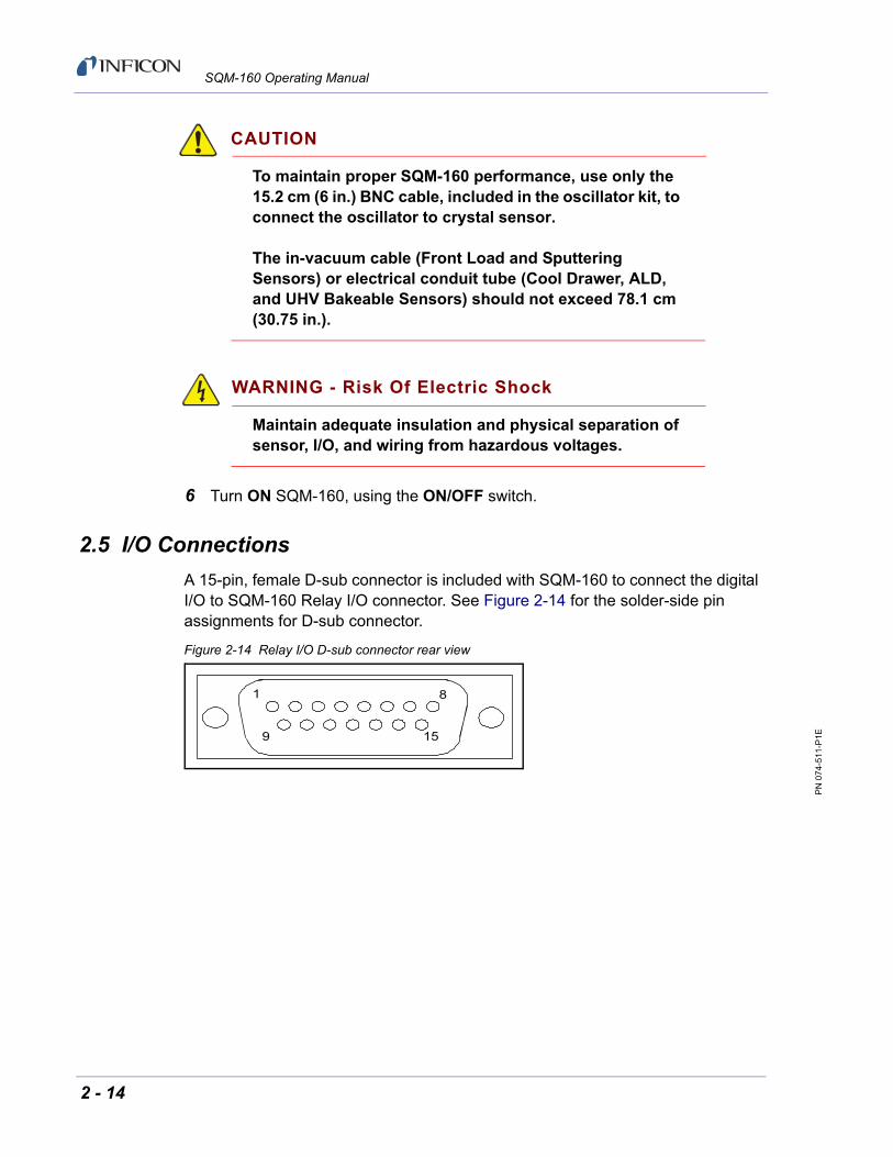
2.5 I/O Connections
A 15-pin, female D-sub connector is included with SQM-160 to connect the digital I/O to SQM-160 Relay I/O connector. See Figure 2-14 for the solder-side pin assignments for D-sub connector.
Figure 2-14 Relay I/O D-sub connector rear view
1 8
9 15
2 - 14

PN
074
-511
-P1E
SQM-160 Operating Manual
WARNING
The inputs are not isolated. The voltage level applied must be limited between 0 and +5 V (dc), with respect to ground.
WARNING
Output relays are rated for 30 V (rms) or 30 V (dc), at 2 A maximum. Provide proper fusing and adequate wiring insulation and separation in case the limits are exceeded.
Table 2-1 Pin functions and descriptions
Pins Function Description
1,2Relay 1
Crystal Fail Relay Activates when all enabled sensors have failed.
3,4Relay 2
Time Setpoint, Dual Sensor, or Sensor 2 Shutter Relay
If RL2 in the System menu is set to:
TIME - Relay 2 activates when time counts down to zero from the programmed Time Setpoint value (see section 3.15 on page 3-15).
DUAL - Relay 2 activates when Sensor 1 fails (see section 3.13 on page 3-13).
SNS2 - Relay 2 activates when the Shutter button is pressed when Sensor 2 is programmed for the active film.
5,6Relay 3
Shutter Relay Controlled by the Shutter button on the front panel. Activated when the Shutter Open indicator is illuminated.
If SNS2 is selected for RL2 in the System menu, the shutter relay activates only if Sensor 1 is programmed for the active film.
7,8Relay 4
Sampling or Thickness Setpoint
If Sampling is ON in the System menu, Relay 4 activates during Sample and open during Hold (see section 3.14 on page 3-14).
If Sampling is OFF, Relay 4 activates when Thickness Setpoint is reached.
9 Zero Time Input Grounding this pin zeroes the setpoint time.
10 Zero Thick Input Grounding this pin zeroes the thickness display.
11 Close Shutter Input Grounding this pin opens the shutter relay.
12 Open Shutter Input Grounding this pin closes the shutter relay.
13,14,15 Ground
2 - 15

PN
074
-511
-P1E
SQM-160 Operating Manual
This page is intentionally blank.
2 - 16

PN
074
-511
-P1E
SQM-160 Operating Manual
Chapter 3Operation
3.1 Introduction
This chapter details the operation of the SQM-160 menus and front panel controls.
3.2 Front Panel Controls
Figure 3-1 SQM-160 front panel
Display 1
Displays Rate/Thickness or Frequency in normal operation.
If multiple sensors are being used and Time is displayed on Display 2, the average of the sensors is displayed. Rotate the Control Knob to display each individual sensor readings.
Displays the setup parameter name in Program mode.
Display 2
Displays deposition Time during normal operation.
When using the Control Knob to display individual sensor readings on Display 1, the sensor number corresponding to reading in Display 1 is displayed on Display 2.
Displays setup parameter values in Program mode.
Display 2
Crystal Status
Indicators
ControlKnob
ControlSection
SetpointIndicators
ConfigurationSection
Display 1
3 - 1

PN
074
-511
-P1E
SQM-160 Operating Manual
Control Section
Zero . . . . . . . . . . . . . . . . . . . . . . . . . Press to zero the thickness reading.
Xtal Life . . . . . . . . . . . . . . . . . . . . . . Press to toggle display between Crystal Life and Rate/Thickness readings.
Shutter. . . . . . . . . . . . . . . . . . . . . . . Press to activate/deactivate shutter relay.
Open/Closed indicator . . . . . . . . . . Displays the status of the shutter relay.
Configuration Section
Program . . . . . . . . . . . . . . . . . . . . . Press to enter/exit Program mode.
Clear . . . . . . . . . . . . . . . . . . . . . . . . Press to cancel a change and return the displayed parameter to original value.
Prev . . . . . . . . . . . . . . . . . . . . . . . . . Press to move to previous parameter. Saves the current setting. If pressed immediately after entering Program mode, allows access to System parameters.
Next . . . . . . . . . . . . . . . . . . . . . . . . . Press to move to next parameter. Saves the current setting.
Setpoint Indicators
Illuminates when the indicated setpoint is reached.
Crystal Status Indicators
Illuminates when the crystal is active and operating properly.
Flashes when an active crystal fails.
Extinguishes when the crystal is not being used.
Control Knob
Used to adjust values or scroll through menu selections.
Press the Control Knob to save the current setting and display the next setting.
Press the Control Knob to enable or disable a sensor channel when editing Sensor Average.
3 - 2

PN
074
-511
-P1E
SQM-160 Operating Manual
3.3 Menu Selection
Two menus provide control for programming SQM-160.
The Film menu customizes each stored film.
The System menu sets values that apply to all films.
The Configuration section of SQM-160 front panel contains four buttons used to access the Program menus. Within the Program menus, the Control Knob also adjusts values and selects menu options. In Program mode, Display 1 indicates the parameter to be changed. Display 2 indicates the value of the selected parameter.
NOTE: If Crystal Life is displayed on SQM-160 display, press Xtal Life to return to normal Rate/Thickness or Frequency display.
To enter the Film menu, press Program. SQM-160 displays the currently selected film. First rotate and then press the Control Knob or Next to select a different film and display the first parameter for the selected film.
To enter the System menu, press Program then press Prev.
Figure 3-2 SQM-160 front panel
Press Next tomove through the
Film menu
Press Prev thenNext to move through
the System menu
PressProgramto access
menus
Display 1
Display 2
Control Knob
3 - 3

PN
074
-511
-P1E
SQM-160 Operating Manual
3.4 Film Menu
The Film menu aids in programming SQM-160 for the materials that will be deposited. Ninety-nine films can be stored, but only one film is active at any time.
1 Press Program to enter Program mode.
2 Rotate the Control Knob to select the desired Film (1 to 99).
3 Press the Control Knob or Next to display the parameters for the selected film.
NOTE: This will set the active film and should not be done while running. Press Program to abort with no change.
4 Press Next or Prev to select other parameters in the Film menu. The selected parameter is seen on Display 1 (refer to Figure 3-2).
5 Rotate the Control Knob to edit the parameter value displayed on Display 2 (refer to Figure 3-2).
6 Press the Control Knob, Next, or Prev to save the displayed value and move to the next material parameter. Press Clear to abandon the change and return to the original value.
7 Press Program to exit the Film menu and return to Normal mode.
NOTE: Figure 3-3 and Table 3-1 detail the parameters available in the Film menu. Instructions for setting specific parameters are detailed in later sections of this chapter.
Figure 3-3 Film menu
ProgramFilm 1
Film 99
- DENSITY- TOOLING- Z-FACTOR- FINL THK- THK SET *- TIME SET *- SAMPLE *- HOLD *- SENS AVG *
- 1- 2- 3
- 6
Film Selection Film Menu Sub-Menu
NOTE: Depending on System menu parameters, selections marked with a *may not be available (see Table 3-1).
- 4- 5
3 - 4

PN
074
-511
-P1E
SQM-160 Operating Manual
Table 3-1 Film menu
Display Description Range Default Units
DENSITY Density of the material being deposited (see Appendix A for common material densities).
0.50 to 99.99 1.00 g/cm3
TOOLING Overall Tooling Factor for this film (see section 3.8 on page 3-11).
10 to 399 100 %
Z-FACTOR Z-Ratio of the material being deposited (see Appendix A for common material Z-Ratios).
0.10 to 9.999 1.0
FINL THK Programmed Final Thickness of deposited material. Illuminates Final Thk indicator when reached.
0.000 to 9999 0.500 kÅ
THK SET Thickness value that activates the Thickness Setpoint relay (Relay 4) and illuminates Thk SP indicator. Not available when Sampling is ON in System menu.
0.000 to 9999 0.000 kÅ
TIME SET Elapsed time that activates the Time Setpoint relay (Relay 2) and illuminates Time SP indicator. Not available when Relay 2 (RL2) is set to DUAL or SNS2 in the System menu.
0:00 to 99:59 0:00 mm:ss
SAMPLE The time for the sensor shutter to remain open when Sampling is enabled in the System menu (see section 3.14 on page 3-14). Not available when Sampling is disabled in System menu.
0 to 5999 0 s
HOLD The time for the sensor shutter to remain closed when Sampling is enabled in the System menu (see section 3.14 on page 3-14). Not available when Sampling is disabled in System menu.
0 to 5999 0 s
SENS AVG Enable/disable crystals for the selected film (see section 3.6 on page 3-9). Not available when Relay 2 (RL2) is set to DUAL in the System menu.
Enabled/
Disabled
Ch1 Enabled
3 - 5
PN
074
-511
-P1E
SQM-160 Operating Manual
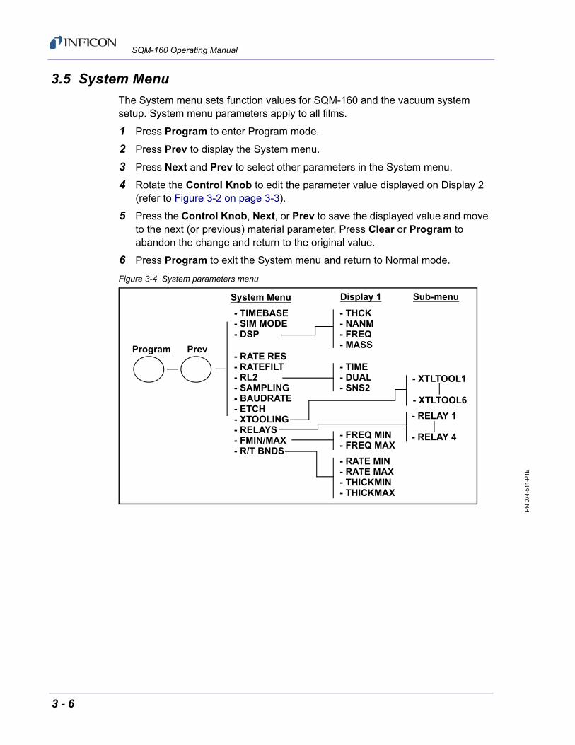
3.5 System Menu
The System menu sets function values for SQM-160 and the vacuum system setup. System menu parameters apply to all films.
1 Press Program to enter Program mode.
2 Press Prev to display the System menu.
3 Press Next and Prev to select other parameters in the System menu.
4 Rotate the Control Knob to edit the parameter value displayed on Display 2 (refer to Figure 3-2 on page 3-3).
5 Press the Control Knob, Next, or Prev to save the displayed value and move to the next (or previous) material parameter. Press Clear or Program to abandon the change and return to the original value.
6 Press Program to exit the System menu and return to Normal mode.
Figure 3-4 System parameters menu
Program Prev
- TIMEBASE- SIM MODE- DSP
- RATE RES- RATEFILT- RL2- SAMPLING- BAUDRATE- ETCH- XTOOLING- RELAYS- FMIN/MAX- R/T BNDS
- THCK - NANM- FREQ- MASS
- TIME- DUAL- SNS2
- FREQ MIN- FREQ MAX
- XTLTOOL1
- XTLTOOL6
- RELAY 1
- RELAY 4
System Menu Display 1
- RATE MIN- RATE MAX- THICKMIN- THICKMAX
Sub-menu
3 - 6

PN
074
-511
-P1E
SQM-160 Operating Manual
Table 3-2 System menu
Display Description Range Default Units
TIMEBASE Time required for a measurement.Longer times yield higher accuracy.
0.10 to 2.00
Increments by 0.05 s
0.25 s
SIM MODE Simulates sensor inputs and frequency/rate readings.
On/Off Off
DSP Selects the value to display on Display 1:
Rate/Thickness in Angstroms
Rate/Thickness in Nanometers
Frequency
Mass
See section 3.9 on page 3-12 for details.
THCK/NANM/FREQ/MASS
THCK
RATE RES Sets rate resolution to 0.01 (high) or 0.1 Å/s (low).
HI/LO LO
RATEFILT Number of rate readings averaged. 1 to 20 8
RL2 Selects the function of Relay 2:
TIME causes Relay 2 to activate when time setpoint is reached (see section 3.15 on page 3-15).
DUAL causes Relay 2 to activate a dual sensor shutter when Sensor 1 fails (see section 3.13 on page 3-13).
SNS2 causes Relay 2 to activate a sensor shutter when Sensor 2 is assigned to a film.
TIME/DUAL/SNS2
Time
SAMPLING When Sampling is ON, the sensor shutter periodically samples the rate, then closes the shutter. SQM-160 holds the same rate reading until the next sample period (see section 3.14 on page 3-14). Sample and Hold times are set in the Film menu (refer to section 3.4).
On/Off Off
BAUDRATE Serial baud rate to computer. 2.40/4.80/9.60/19.20/38.40/57.60/115.2
19.20 kbps
ETCH Sets rate negative for etching. On/Off Off
XTOOLING Tooling value assigned to each sensor. See section 3.8, Sensor Tooling, on page 3-11.
10 to 399 100 %
3 - 7

PN
074
-511
-P1E
SQM-160 Operating Manual
RELAYS Assigns normally open or normally closed operation for each relay.
NOTE: All relays are open with power OFF.
nO/nC nO
FMIN/MAX Sub-menu sets minimum and maximum crystal frequencies (see section 3.7 on page 3-10).
Min: 1.00 to 6.40
Max: 1.10 to 6.50
5.00
6.10
MHz
R/T BNDS Rate and Thickness Bounds sub-menu for analog outputs (see section 3.20 on page 3-18).
See below
RATE MIN Deposition rate for zero output (0 V). Must be set lower than RATE MAX.
-99 to 999 0 Å/s
RATE MAX Deposition rate for full-scale output (+5 V(dc)). Must be set higher than RATE MIN.
-99 to 999 100 Å/s
THICKMIN Thickness for zero output (0 V). Must be set lower than THICKMAX.
0.000 to 9999 0.000 kÅ
THICKMAX Thickness for full scale output (+5 V (dc)). Must be set higher than THICKMIN.
0.000 to 9999 1.000 kÅ
Table 3-2 System menu (continued)
Display Description Range Default Units
3 - 8

PN
074
-511
-P1E
SQM-160 Operating Manual
3.6 Sensor Selection
SQM-160 comes standard with two sensor inputs. Four additional sensors are available by adding a Sensor Option Card. A specific sensor can be assigned to each film, or multiple sensors can be assigned to a film for sensor averaging. The averaging option provides more uniform coverage of the deposition area and provides backup sensor capability. If one of the sensors assigned to a film fails, that sensor is automatically removed from rate/thickness calculations.
NOTE: If Relay 2 (RL2) is set to DUAL in the System menu, Sensors 1 and 2 are set as a primary/secondary sensor pair and sensor averaging is disabled (see section 3.13 on page 3-13 for information on dual sensors).
To assign a sensor, or sensors, to a film:
1 Press Program to enter Program mode.
2 Use the Control Knob to scroll to the desired film (1 to 99).
3 Press the Control Knob or Next to enter the Film menu for the selected film and set the selected film as the active film.
4 Press Next until SENS AVG is displayed.
5 Rotate the Control Knob to display each sensor in Display 2.
6 Press the Control Knob to toggle the indicated sensor On/Off.
The Crystal Status indicators indicate the sensor status for each sensor:
If the indicator is extinguished, the sensor is disabled.
If the indicator is illuminated, the sensor is enabled and SQM-160 is receiving valid readings.
If the indicator is blinking, the sensor is enabled, but SQM-160 is not receiving valid readings (crystal fail) (see Chapter 6, Troubleshooting and Maintenance).
7 Continue selecting sensors until the Crystal Status indicators indicate the desired setup.
8 Press Program to exit the Film menu and return to Normal mode.
9 Rotate the Control Knob to display each enabled sensor reading on Display 1.
When an individual sensor number is displayed in Display 2, the number in Display 1 is the individual reading for that sensor.
When time is displayed in Display 2, the number in Display 1 is the average of all assigned sensors.
3 - 9

PN
074
-511
-P1E
SQM-160 Operating Manual
3.7 Sensor Frequency
Sensor Minimum and Maximum frequencies establish the operating range for the sensing quartz crystals. Both values are used to determine the % life that is displayed in Xtal Life mode.
When the sensor frequency reads below the minimum or above the maximum, SQM-160 indicates a sensor failure (crystal fail) with a flashing Crystal Status indicator.
To set sensor minimum and maximum frequencies:
1 Press Program to enter Program mode.
2 Press Prev to enter the System menu.
3 Press Next until FMIN/FMAX displays on Display 1.
4 Press the Control Knob to display FREQ MIN on Display 1.
5 Rotate the Control Knob to edit the minimum operating frequency on Display 2 (typically 5.0 MHz for a 6 MHz crystal).
6 Press the Control Knob to accept the minimum value and display FREQ MAX on Display 1.
7 Rotate the Control Knob to edit the maximum operating frequency on Display 2 (typically 6.0 or 6.1 MHz for a 6 MHz crystal).
8 Press the Control Knob to accept the maximum value.
9 Press Program to exit the System menu and return to Normal mode.
Crystals sometimes fail unexpectedly, or exhibit erratic frequency shifts (mode hopping) before total failure. Depending on the material, crystals may fail well before the typical 5 MHz minimum. If the crystals consistently fail early, set FREQ MIN to a value higher than 5 MHz to provide a Crystal Life warning that is consistent with actual failure.
A sensor crystal with an initial value that exceeds the maximum frequency will also cause a flashing Crystal Status indicator. The maximum frequency can be set slightly above the nominal values with no effect on accuracy.
3 - 10
PN
074
-511
-P1E
SQM-160 Operating Manual
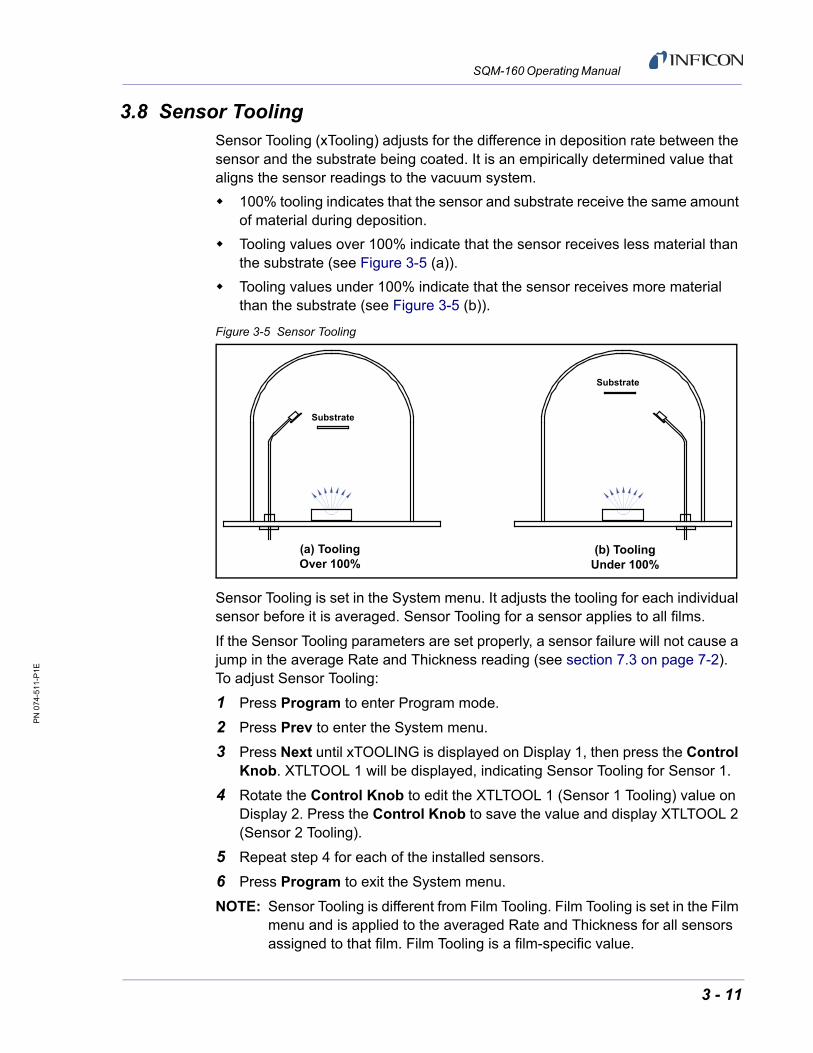
3.8 Sensor ToolingSensor Tooling (xTooling) adjusts for the difference in deposition rate between the sensor and the substrate being coated. It is an empirically determined value that aligns the sensor readings to the vacuum system.
100% tooling indicates that the sensor and substrate receive the same amount of material during deposition.
Tooling values over 100% indicate that the sensor receives less material than the substrate (see Figure 3-5 (a)).
Tooling values under 100% indicate that the sensor receives more material than the substrate (see Figure 3-5 (b)).
Figure 3-5 Sensor Tooling
Sensor Tooling is set in the System menu. It adjusts the tooling for each individual sensor before it is averaged. Sensor Tooling for a sensor applies to all films.
If the Sensor Tooling parameters are set properly, a sensor failure will not cause a jump in the average Rate and Thickness reading (see section 7.3 on page 7-2). To adjust Sensor Tooling:
1 Press Program to enter Program mode.
2 Press Prev to enter the System menu.
3 Press Next until xTOOLING is displayed on Display 1, then press the Control Knob. XTLTOOL 1 will be displayed, indicating Sensor Tooling for Sensor 1.
4 Rotate the Control Knob to edit the XTLTOOL 1 (Sensor 1 Tooling) value on Display 2. Press the Control Knob to save the value and display XTLTOOL 2 (Sensor 2 Tooling).
5 Repeat step 4 for each of the installed sensors.
6 Press Program to exit the System menu.
NOTE: Sensor Tooling is different from Film Tooling. Film Tooling is set in the Film menu and is applied to the averaged Rate and Thickness for all sensors assigned to that film. Film Tooling is a film-specific value.
(a) ToolingOver 100%
(b) ToolingUnder 100%
Substrate
Substrate
3 - 11

PN
074
-511
-P1E
SQM-160 Operating Manual
3.9 Display Units
SQM-160 can display crystal measurements in several different units.
To select the display units:
1 Press Program to enter Program mode.
2 Press Prev to enter the System menu.
3 Press Next until DSP... is displayed on Display 1.
4 Rotate the Control Knob to select the desired display mode:
THCK — Rate in Å/s, Thickness in kÅ
NANM — Rate in nm/s, Thickness in µm
MASS — Rate in ng/cm2/s, Mass in µg/cm2
FREQ — Frequency in Hz
NOTE: When NANM is selected a lowercase n is displayed between the rate and thickness values. When MASS is selected a lowercase m is displayed between the rate and thickness values.
5 Press the Control Knob, Next, or Prev to accept the choice.
6 Press Program to exit the System menu and return to Normal mode.
NOTE: The Display Units setting does not affect data returned through remote communications or analog outputs.
3.10 Crystal Life
SQM-160 calculates the crystal life value based on the current frequency compared to the FMIN/FMAX values set in the System menu (refer to section 3.5 on page 3-6 and section 3.7 on page 3-10). A new crystal should indicate between 95 and 100% crystal life.
To display the remaining crystal life for the sensors used by the currently active film:
1 Press Xtal Life.
2 The sensor is displayed on Display 1 and the % remaining life is displayed on Display 2.
3 Rotate the Control Knob to display the % life of other sensors active for the selected film.
4 Press Xtal Life again to return to normal rate/thickness or frequency display.
NOTE: Program mode is not available while the crystal life display is active.
3 - 12

PN
074
-511
-P1E
SQM-160 Operating Manual
NOTE: Usable crystal life depends on the material being evaporated and other process characteristics. Rate noise and other failure modes may be observed before the crystal life value reaches 0%.
3.11 Zero ThicknessBefore starting each film deposition, reset the SQM-160 Thickness value to zero. To zero Thickness, press Zero on the front panel Control section.
In addition to zeroing Thickness, pressing Zero has the following effects:
The Time display is reset to the programmed value and starts counting down.
The Thickness and Time Setpoint relays deactivate.
The Time SP, Thk SP, and Final Thk indicators extinguish.
3.12 Shutter Operation
The SQM-160 Shutter button controls a relay (Relay 3) that is normally connected to the source shutter. To activate or deactivate the Shutter relay, press Shutter.
The Open and Closed indicators illuminate to indicate the shutter status.
NOTE: If Relay 2 (RL2) is set to SNS2 in the System menu, the operation of the Shutter relay changes slightly. In this case, Relay 3 will activate only if Sensor 1 is assigned to the active film. If Sensor 2 is assigned to the active film, Relay 2 will activate instead.
3.13 Dual Sensors
Dual sensors provide a backup (secondary) crystal should the primary crystal fail. When Relay 2 (RL2) is programmed for DUAL in the System menu, SQM-160 will automatically switch to Sensor 2 when Sensor 1 readings stop or become erratic. Relay 2 will activate when Sensor 2 is in operation to actuate a dual sensor shutter.
To program SQM-160 for dual sensors:
1 Press Program to enter Program mode.
2 Press Prev to enter the System menu.
3 Press Next until RL2 is displayed on Display 1.
4 Rotate the Control Knob clockwise to select DUAL sensor function.
5 Press the Control Knob to accept the value.
6 Press Program to exit the System menu and return to Normal mode.
7 In the Film menu, assign only Sensor 1 to the film. The backup Sensor 2 is automatically assigned internally.
3 - 13

PN
074
-511
-P1E
SQM-160 Operating Manual
NOTE: Relay 2 is a multi-function relay. Relay 2 can be programmed as a dual sensor shutter, it will activate when a programmed time has elapsed, or as a Sensor 2 shutter relay. The function of Relay 2 is set in the System menu RL2 parameter (refer to section 3.5 on page 3-6 for more information about SQM-160 System parameters or see section 3.19 on page 3-18 for more information about SQM-160 relay functions).
3.14 Rate SamplingWith Rate Sampling enabled, SQM-160 opens a sensor shutter for a fixed time in order to sample the rate. SQM-160 then closes the shutter and for a fixed time. While the shutter is closed (Hold mode), SQM-160 calculates thickness based on the last sampled rate.
NOTE: Rate sampling can significantly extend crystal life in high deposition rate and long processes. However, unless the process is very stable, the thickness calculation during Hold mode may be incorrect. Do not use rate sampling if the rates vary during deposition.
To program SQM-160 for Rate Sampling:
1 Press Program to enter Program mode.
2 Press Prev to enter the System menu.
3 Press Next until SAMPLING is displayed on Display 1.
4 Rotate the Control Knob clockwise to set SAMPLING to ON.
5 Press the Control Knob to accept the value.
6 Press Program to exit the System menu and return to Normal mode.
7 Press Program to return to Program mode.
8 Rotate the Control Knob to select the desired film (1 to 99), then press the Control Knob or Next to display the Film menu for the selected film.
9 Press Next until SAMPLE is displayed on Display 1.
10 Rotate the Control Knob to edit the SAMPLE value displayed on Display 2. Press the Control Knob to accept the SAMPLE value and display HOLD.
NOTE: SAMPLE is the amount of time the sensor shutter will remain open.
11 Rotate the Control Knob to edit the HOLD value displayed on Display 2. Press the Control Knob to accept the HOLD value.
NOTE: HOLD is the amount of time the sensor shutter will remain closed. The displayed Rate during this time is the last sampled rate.
12 Press Program to exit the Film menu and return to Normal mode.
3 - 14

PN
074
-511
-P1E
SQM-160 Operating Manual
NOTE: Relay 4 is a dual function relay. It can be programmed either for Rate Sampling or as a Thickness Setpoint relay (see section 3.16, Thickness Setpoint, on page 3-16 or refer to section 2.5, I/O Connections, on page 2-14 for relay wiring). This relay cannot be programmed for more than one function.
3.15 Time Setpoint
The Time Setpoint provides a convenient way to signal a timed event when Relay 2 (RL2) is set to TIME in the System menu. After a programmed time period (TIME SET), the Time SP indicator illuminates and Relay 2 activates. Relay 2 will deactivate and the time will reset when Zero is pressed.
To program the Time Setpoint:
1 Press Program to enter Program mode.
2 Press Prev to enter the System menu.
3 Press Next until RL2 is displayed on Display 1.
4 Rotate the Control Knob clockwise to select TIME. Press the Control Knob to accept the value.
5 Press Program to exit the System menu and return to Normal mode.
6 Press Program to return to Program mode.
7 Rotate the Control Knob to select the desired film (1 to 99), then press the Control Knob or Next to display the Film menu for the selected film.
8 Press Next until TIME SET is displayed on Display 1.
9 Rotate the Control Knob to edit the TIME SET value displayed on Display 2 and press the Control Knob to accept the value.
10 Press Program to exit the Film menu and return to Normal mode.
NOTE: Relay 2 is a multi-function relay. It can be programmed as a dual sensor shutter to activate when a programmed time has elapsed, or as a Sensor 2 shutter relay. The function of Relay 2 is set in the System menu RL2 parameter (refer to section 3.5 on page 3-6 for more information about SQM-160 System parameters or see section 3.19 on page 3-18 for more information about SQM-160 relay functions).
3 - 15

PN
074
-511
-P1E
SQM-160 Operating Manual
3.16 Thickness Setpoint
The Time Setpoint provides a convenient way to signal a thickness based event when SAMPLING is set to OFF in the System menu. When the programmed thickness is reached, the Thick SP indicator illuminates and Relay 4 deactivates. Press Zero to deactivate the relay and zero thickness.
NOTE: Thickness Setpoint is independent of Final Thickness, which always closes the source shutter.
To program the Thickness Setpoint:
1 Press Program to enter Program mode.
2 Press Prev to enter the System menu.
3 Press Next until SAMPLING is displayed on Display 1.
4 Rotate the Control Knob clockwise to set SAMPLING to OFF. Press the Control Knob to accept the value.
5 Press Program to exit the System menu and return to Normal mode.
6 Press Program to return to Program mode.
7 Rotate the Control Knob to select the desired film (1 to 99), then press the Control Knob or Next to display the Film menu for the selected film.
8 Press Next until THK SET, not FINL THK, is displayed on Display 1.
9 Rotate the Control Knob to edit the THK SET value displayed on Display 2. Press the Control Knob to accept the value.
10 Press Program to exit the Film menu and return to Normal mode.
NOTE: Relay 4 is a dual function relay. It can be programmed either for Rate Sampling or for as a Thickness Setpoint relay (see section 3.14, Rate Sampling, on page 3-14 or refer to section 2.5, I/O Connections, on page 2-14 for relay wiring). This relay cannot be programmed for more than one function.
3 - 16

PN
074
-511
-P1E
SQM-160 Operating Manual
3.17 Simulate Mode
In Simulate mode, SQM-160 simulates attached sensors and provides a simplified way to become familiar with the SQM-160 front panel controls and programming. It is possible to open or close the shutter to simulate deposition, zero readings, and display crystal life. It is also possible to test the Time and Thickness Setpoint relays and indicators.
To enter Simulate mode:
1 Press Program to enter Program mode.
2 Press Prev to enter the System menu.
3 Press Next until SIM MODE is displayed on Display 1.
4 Rotate the Control Knob to set SIM MODE to ON or OFF.
5 Press the Control Knob to accept the value.
6 Press Program to exit the System menu and return to Normal mode.
3.18 Defaulting the Memory
CAUTION
Performing this procedure will default SQM-160 to factory settings and delete all parameters set by the user. Do not perform this procedure before creating a backup configuration file using SQM-160 Comm software.
1 Turn ON SQM-160. Immediately press and hold the buttons described in either 1a or 1b, depending on the SQM-160 firmware version.
NOTE: The buttons must be pressed and held immediately after positioning the ON/OFF switch to ON or the procedure will not work.
1a To clear only Film parameters:
Press and hold ZERO + XTAL LIFE + SHUTTER while SQM-160 turns ON. Continue holding and proceed to step 2.
1b To clear only System parameters (firmware version v4.10 and higher):
Press and hold ZERO + XTAL LIFE + SHUTTER + CONTROL KNOB while SQM-160 turns ON. Continue holding and proceed to step 2.
2 Continue to hold the buttons from 1a or 1b until ERROR 00 is displayed, briefly followed by SQM-160 operating display. If parameters have not been defaulted and ERROR 00 did not display, return to step 1.
3 Turn SQM-160 OFF, then ON. SQM-160 should now turn ON without displaying errors.
3 - 17

PN
074
-511
-P1E
SQM-160 Operating Manual
NOTE: Defaulting the SQM-160 memory can also be done using the SQM-160 Comm software (see section 4.6 on page 4-11).
3.19 Relay Operation
The four SQM-160 relays are physically single-pole, normally-open (1FormA) relays. Each relay can be programmed to act as either normally-open or normally-closed during SQM-160 operation.
NOTE: All relays will open if SQM-160 is turned OFF or loses power (refer to section 2.5 on page 2-14 for relay wiring).
To set the relay operating mode:
1 Press Program to enter Program mode.
2 Press Prev to enter the System menu.
3 Press Next until RELAYS displays on Display 1.
4 Press the Control Knob to display Relay 1 on Display 1.
5 Rotate the Control Knob to select nO (normally open) or nC (normally closed). Press the Control Knob to accept the value and display the next relay.
6 Repeat step 4 for each of the four relays.
7 Press Program to exit the System menu and return to Normal mode.
3.20 Analog Output Configuration
SQM-160 features analog outputs that will produce a 0 to 5 V (dc) representative of the current rate or thickness. Analog outputs must be set to match the device that will be attached to the Rate or Thickness output.
To set up the analog outputs in the System menu:
1 Press Program to enter Program mode.
2 Press Prev to enter the System menu.
3 Press Next until R/T BNDS is displayed on Display 1.
4 Press the Control Knob to display RATE MIN on Display 1.
5 Rotate the Control Knob to set the RATE MIN value appropriately for a 0 V (dc) output.
6 Press the Control Knob to save the value and display RATE MAX on Display 1.
7 Rotate the Control Knob to set the RATE MAX value appropriately for a 5 V (dc) output.
8 Press the Control Knob to save the value and display THICKMIN on Display 1.
3 - 18
PN
074
-511
-P1E
SQM-160 Operating Manual
9 Repeat steps 5 to 8 to adjust the Thickness output values (THICKMIN and THICKMAX).
10 Press Program to exit the System menu and return to Normal mode. (Refer to section 3.5 on page 3-6 for more information on setting SQM-160 System parameters.)
3.21 Depositing a Film
After all Film and System menu parameters are entered, it is possible to deposit a film. Follow the procedure below to begin deposition.
1 Verify Sensor Operation
Verify that the Crystal Status indicator(s) for the measuring sensor(s) is illuminated and not flashing.
2 Display Rate/Thickness
Display 1 should display Rate on the left and Thickness on the right.
If the Crystal Life display mode is active, press the Xtal Life button to return to Normal mode.
If the Program mode is active, press Program to return to Normal mode.
3 Zero Thickness
If needed, press Zero to zero the Thickness reading.
4 Start Deposition
Apply power to the source evaporation supply. If the SQM-160 shutter relay is connected (refer to section 2.5 on page 2-14), press Shutter to open the source shutter and begin deposition.
Rate and Thickness displays should display non-zero values. If the Rate and Thickness displays continue to display zero, check the system setup to ensure evaporation is occurring and deposition material is reaching the sensor.
If the display is erratic or noisy, refer to the troubleshooting information found in Chapter 6 or the sensor operating manual.
If the rate and thickness readings do not match expectations, refer to section 3.4 on page 3-4 for information on setting Film parameters (Density, Z-Ratio (Z-Factor), Film Tooling) and section 3.8 on page 3-11 for information on setting Sensor Tooling.
3 - 19

PN
074
-511
-P1E
SQM-160 Operating Manual
This page is intentionally blank.
3 - 20

PN
074
-511
-P1E
SQM-160 Operating Manual
Chapter 4SQM-160 Comm Software
4.1 Introduction
SQM-160 Comm software communicates with SQM-160 to allow remote instrument setup and data logging.
Features include:
Selecting a Film on SQM-160, then opening the shutter to start deposition.
Viewing SQM-160 readings in both numerical and graphical format.
Storing SQM-160 log data in a spreadsheet-compatible format.
Creating and storing an unlimited number of film setups.
Downloading films to and uploading films from SQM-160.
Modifying the SQM-160 system setup parameters.
NOTE: This chapter discusses the functionality of SQM-160 Comm V2 software version 2.60. Previous versions of SQM-160 Comm software may differ in form and function. Refer to an older manual revision for information about previous software versions.
Consult Chapter 5, Communications for information on connecting to an SQM-160 and establishing communication with this program.
4.2 Installation
The following instructions are for installation of SQM-160 Comm software.
1 Click Windows Explorer or File Explorer >> Computer >> (CD drive letter:) INFICON Technical Documentation>> SQM160 Monitor.
2 Double-click SQM 160 V2 v2.6.0 Setup.exe.
3 The InstallShield Wizard will display.
4 Click Next.
5 Select I accept the terms in the license agreement.
6 Click Next.
7 Click Next to accept the default installation location or click Change to change the installation folder).
8 Click Install to start the software installation.
4 - 1

PN
074
-511
-P1E
SQM-160 Operating Manual
9 Click Finish. The INFICON USB Installer - InstallShield Wizard window will display.
10 Click Next.
11 Select I accept the terms in the license agreement.
12 Click Next.
13 Enter User Name and Organization information.
14 Click Next.
15 Click Install.
16 Click Finish. The INFICON Thinfilm USB Device Driver Driver Installer window will display.
17 Click Next.
18 Click Finish.
4.2.1 Update of an Older Version of SQM-160 Comm
If an older version of SQM-160 Comm software is being updated:
1 Navigate to Windows Control Panel >> Programs.
2 In Programs, select SQM-160 Comm and click Uninstall to remove the old version of SQM-160 Comm software.
3 Install the latest version of SQM-160 Comm software (refer to section 4.2).
NOTE: It may be necessary to remove previously installed USB drivers for the new drivers to install correctly. This is done using steps 1 to 3 above to uninstall any INFICON USB drivers or Silicon Laboratories USB drivers. Silicon Laboratories USBXpress Device (Driver Removal) is a common driver for previous devices.
4 - 2

PN
074
-511
-P1E
SQM-160 Operating Manual
4.3 Start the SQM-160 V2 Comm software.
For Windows 7
Click Windows Start icon >> All Programs >> INFICON >> SQM-160 Comm V2.
or
Double click the SQM-160 Comm V2 shortcut icon on the desktop.
For Windows 8
In the Start window, click the SQM-160 Comm V2 icon.
If the SQM-160 Comm V2 icon is not visible:
Click Search >> Apps.
Type SQM-160 in the Search box.
Click the SQM-160 Comm V2 icon.
The SQM-160 Comm Main window will display (see Figure 4-1).
4 - 3

PN
074
-511
-P1E
SQM-160 Operating Manual
4.4 Main Window
The Main window displays and graphs process data and allows navigation to other windows for editing process parameters (see Figure 4-1).
Figure 4-1 SQM-160 Comm Main window - online
On program startup, SQM-160 Comm software attempts to find an SQM-160 using the last communications port settings. It may take a few seconds to establish a connection. At this time, Initializing... will be displayed at the bottom of the Main window.
If SQM-160 Comm software is able to connect to SQM-160, the SQM-160 firmware version is displayed at the top of the Main window and On Line - Ready is displayed at the bottom of the Main window (refer to Figure 4-1).
4 - 4
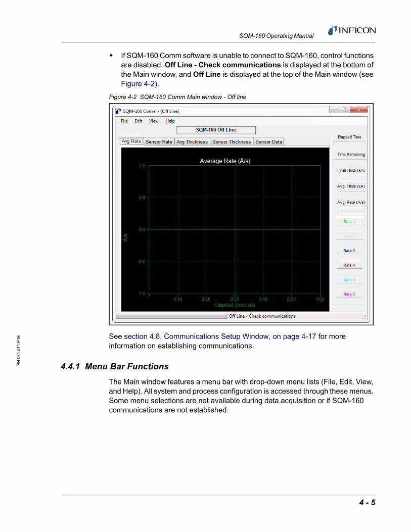
PN
074
-511
-P1E
SQM-160 Operating Manual
If SQM-160 Comm software is unable to connect to SQM-160, control functions are disabled, Off Line - Check communications is displayed at the bottom of the Main window, and Off Line is displayed at the top of the Main window (see Figure 4-2).
Figure 4-2 SQM-160 Comm Main window - Off line
See section 4.8, Communications Setup Window, on page 4-17 for more information on establishing communications.
4.4.1 Menu Bar Functions
The Main window features a menu bar with drop-down menu lists (File, Edit, View, and Help). All system and process configuration is accessed through these menus. Some menu selections are not available during data acquisition or if SQM-160 communications are not established.
4 - 5

PN
074
-511
-P1E
SQM-160 Operating Manual
4.4.1.1 File Menu
Data Log . . . . . . . . . . . . . . . . . . . . . Opens the Data Log window for configuration of the SQM-160 Data Log function (see section 4.5 on page 4-9).
Print . . . . . . . . . . . . . . . . . . . . . . . . . Prints the Sensor Data tab, Avg Rate tab, Sensor Rate tab, Avg Thickness tab, and Sensor Thickness tab. When initially clicked, opens the Print window for configuration of printers and printing preferences.
NOTE: Print will not display the Print window a second time while SQM-160 Comm software is open. Exit and open SQM-160 Comm software to display the Print window for editing configuration of printers and printing preferences.
Screen Image to File
Current View to JPG. . . . . . . . . . . . Saves a screenshot of the currently opened tab in .jpg format to the selected folder. If a folder has not been selected using Select JPG Folder, images will be saved to the INFICON SQM-160 directory.
All Views to JPGs . . . . . . . . . . . . . . Saves a screenshot of all tabs in .jpg format to the selected folder. If a folder has not been selected using Select JPG Folder, images will be saved to the INFICON SQM-160 directory.
Select JPG Folder . . . . . . . . . . . . . Allows for selection of a default save location for all Screen Image files.
Exit. . . . . . . . . . . . . . . . . . . . . . . . . . Exits the program.
4 - 6

PN
074
-511
-P1E
SQM-160 Operating Manual
4.4.1.2 Edit Menu
Films . . . . . . . . . . . . . . . . . . . . . . . . Opens the Films window for editing of Film parameters (see section 4.6 on page 4-11).
System. . . . . . . . . . . . . . . . . . . . . . . Opens the System Parameters window for editing of System parameters (see section 4.7 on page 4-15).
Communications . . . . . . . . . . . . . . Opens the SQM-160 Comm Setup menu for editing of remote communications settings (see section 4.8 on page 4-17).
Graph Settings . . . . . . . . . . . . . . . . Opens the Configure Graph(s) window for editing of graph settings (see section 4.9 on page 4-21).
4.4.1.3 View Menu
The View menu selects which graph is viewed and also what information is displayed on right side of the Main window. A check mark indicates the currently selected information. Graph selection can also be done by clicking on the tabs at the top of each graph (see section 4.4.2).
Average Rate Graph . . . . . . . . . . . . Displays a graph of the average rate of all active sensors.
Sensor Rates Graph . . . . . . . . . . . . Displays a graph of the individual rate of each active sensor.
Average Thickness Graph . . . . . . . Displays a graph of the average thickness of all active sensors.
Sensor Thickness Graph . . . . . . . . Displays a graph of the individual thickness of each active sensor.
Sensor Rates Display. . . . . . . . . . . Displays individual sensor rates in Å/s on the right side of the Main window.
Sensor Thickness Display . . . . . . . Displays individual sensor thicknesses in kÅ on the right side of the Main window.
Sensor Frequency Display . . . . . . Displays individual sensor frequencies in Hz on the right side of the Main window.
4.4.1.4 Help Menu
About . . . . . . . . . . . . . . . . . . . . . . . . Displays the SQM-160 About window (see section 4.10 on page 4-23).
Help . . . . . . . . . . . . . . . . . . . . . . . . . Function not available.
4 - 7

PN
074
-511
-P1E
SQM-160 Operating Manual
4.4.2 Main Window Control Functions
Film . . . . . . . . . . . . . . . . . . . . . . . . . This drop-down list selects the film on SQM-160 that will be used for rate/thickness measurements.
Start/Stop . . . . . . . . . . . . . . . . . . . . Starts or stops SQM-160 data acquisition. Graphing and display of readings from SQM-160 starts/stops immediately when this control is toggled. When data logging is configured (see section 4.5), logging begins when Start is clicked.
Open/Close Shutter . . . . . . . . . . . . Toggles the SQM-160 shutter relay. Opening the shutter automatically starts SQM-160 data acquisition. However, closing the shutter does not automatically stop data acquisition.
Zero . . . . . . . . . . . . . . . . . . . . . . . . . Zeros the thickness reading on SQM-160.
The following Main window features display readings from SQM-160:
Graph & Sensor Data Tabs . . . . . . Displays readings from SQM-160. Use the tabs to select the desired type of information to display.
Avg Rate . . . . . . . . . . . . . . . . . . . . . Displays a graph of the average rate of all active sensors.
Sensor Rate . . . . . . . . . . . . . . . . . . Displays a graph of the individual rate of each active sensor.
Avg Thickness . . . . . . . . . . . . . . . . Displays a graph of the average thickness of all active sensors.
Sensor Thickness . . . . . . . . . . . . . Displays a graph of the individual thickness of each active sensor.
Sensor Data . . . . . . . . . . . . . . . . . . Displays average and individual sensor rate, thickness, and frequency in a table format.
Elapsed Time . . . . . . . . . . . . . . . . . Displays the elapsed time since Start was clicked.
Time Remaining . . . . . . . . . . . . . . . Displays the calculated deposition time remaining based on the current thickness, current rate, and final thickness setpoint.
4 - 8

PN
074
-511
-P1E
SQM-160 Operating Manual
Final Thickness . . . . . . . . . . . . . . . The desired deposition thickness for the selected film. Final thickness can be edited in the Film window (see section 4.6 on page 4-11).
Average Thickness . . . . . . . . . . . . . The current film thickness, based on the average of all sensors assigned to the selected film.
Average Rate. . . . . . . . . . . . . . . . . . The current deposition rate, based on the average of all sensors assigned to the selected film.
Rate 1 to 6 . . . . . . . . . . . . . . . . . . . . The individual sensor rate readings.
NOTE: Rate 1 to 6 can be replaced with Thickness 1 to 6 or Frequency 1 to 6 using the View menu (refer to section 4.4.1.3 on page 4-7).
4.5 Data Log Window
SQM-160 Comm software has the ability to log data to a .txt file at user-specified time intervals. Click File >> Data Log on the Main window to display the Data Log window. The Data Log window configures the SQM-160 Comm software data logging function (see Figure 4-3).
NOTE: Once configured, data logging will not begin until Start is clicked.
Figure 4-3 Data Log window
4 - 9

PN
074
-511
-P1E
SQM-160 Operating Manual
Data is saved in tab delimited .txt file format for easy viewing or importing into a spreadsheet (see Table 4-1).
4.5.1 Log File Pane
Select the type of log file, filename and location for the data log, or view the currently saved data log.
None . . . . . . . . . . . . . . . . . . . . . . . . Data logging is disabled.
Overwrite. . . . . . . . . . . . . . . . . . . . . The log file will be overwritten each time data logging is started with Start or Open Shutter on the Main window.
Append . . . . . . . . . . . . . . . . . . . . . . Data is added to the end of the log file each time data logging is started with Start or Open Shutter.
By Run # . . . . . . . . . . . . . . . . . . . . . A new log file is created each time logging is started. The run number is added to the end of each filename.
New . . . . . . . . . . . . . . . . . . . . . . . . . Displays a file open dialog box to allow selection or creation of a new log file and/or path.
View . . . . . . . . . . . . . . . . . . . . . . . . . Displays the current log file using the default Windows text file viewer.
Table 4-1 Data in tab delimited .txt file format
Start: Date: 9/10/2013 Time: 14:04:41 Film: ALUM
Time AvgThk AvgRate Thk1 Rate1 ......
0.00 0.000 1.10 0.000 1.10
0.50 0.000 1.11 0.000 1.11
1.00 0.001 1.10 0.001 1.10
1.50 0.001 1.10 0.001 1.10
2.00 0.002 1.10 0.002 1.10
.....
End: Date: 9/10/2013 Time: 14:04:44 Film: ALUM
4 - 10

PN
074
-511
-P1E
SQM-160 Operating Manual
4.5.2 Duration Pane
Select the duration of the data log.
Unlimited . . . . . . . . . . . . . . . . . . . . Allows the data log to continue as indefinitely.
Range . . . . . . . . . . . . . . . . . . . . . . . The log will start and end according to the Time Range settings (see section 4.5.3).
4.5.3 Time Range Pane
Set the start and end time for the data log.
NOTE: Settings in the Time Range pane are only available if Range is selected in the Duration pane.
Start Time . . . . . . . . . . . . . . . . . . . . The elapsed time when data logging begins. Set the value in hours, minutes, and seconds.
End Time . . . . . . . . . . . . . . . . . . . . . The elapsed time when data logging ends. Set the value in hours, minutes, and seconds.
4.5.4 Sampling Interval Pane
The Sampling Interval is the elapsed time between data log entries in minutes and seconds. An interval value of zero causes data to be logged as quickly as possible. This time will vary depending on system configuration.
4.6 Films Window
Click Edit >> Films on the Main window to display the Films window. This window allows films to be created, edited, and saved to a file or transferred to/from SQM-160. The films are stored in an SQM-160 configuration file in an Extensible Markup Language (XML) format, Monitor.xml, in the SQM-160 Comm software program directory by default.
The name of the .xml file being used to store films is displayed at the top of the Films menu. Films uploaded from SQM-160 are stored automatically in a file named UploadData.xml.
4 - 11

PN
074
-511
-P1E
SQM-160 Operating Manual
Figure 4-4 Films window
Data Base . . . . . . . . . . . . . . . . . . . . Click to create a new configuration file, save the current setting to a new or existing configuration file, or open an existing configuration file.
Films List . . . . . . . . . . . . . . . . . . . . Lists the films (1 to 99) available for editing and download. Click Upload Al <- to update the Films List with films currently stored in SQM-160.
Close . . . . . . . . . . . . . . . . . . . . . . . . Exits the Films window and saves changes to the current .xml file.
Upload Al <- . . . . . . . . . . . . . . . . . . Reads films stored in SQM-160 to the Films List and automatically saves the read films to the file UploadData.xml.
DnLoad All -> . . . . . . . . . . . . . . . . . Saves all films to SQM-160.
NOTE: Clicking DnLoad All -> will overwrite any films stored in SQM-160.
Download -> . . . . . . . . . . . . . . . . . . Saves the film parameters currently displayed to SQM-160.
NOTE: Clicking Download -> will overwrite any films stored in SQM-160.
Defaults . . . . . . . . . . . . . . . . . . . . . . Resets film and system parameters to default values.
Add Material . . . . . . . . . . . . . . . . . . Enter a new material into the Materials list.
4 - 12

PN
074
-511
-P1E
SQM-160 Operating Manual
The following editable film parameters pertain to the selected film in the Films List.
Film Name . . . . . . . . . . . . . . . . . . . . The name that is displayed in the Films List and in the SQM-160 Film menu. Names are limited to eight alphanumeric characters. No special characters are allowed.
NOTE: While SQM-160 does not allow spaces or lowercase characters in film names (see section 5.4.2 on page 5-13), it is acceptable to enter spaces and lowercase characters using SQM-160 Comm software. SQM-160 Comm software will convert characters to the correct format when downloading to SQM-160.
Final Thickness . . . . . . . . . . . . . . . The desired film thickness setpoint. When the Final Thickness is reached, the SQM-160 shutter relay deactivates (closes the source shutter) and Final Thk indicator illuminates on the SQM-160 front panel. Values from 0 to 9999 kÅ are valid.
Thick Setpoint. . . . . . . . . . . . . . . . . A thickness setpoint that closes the Thickness Setpoint relay and illuminates the Thk SP indicator on the SQM-160 front panel. This does not affect the source shutter. Values from 0 to 9999 kÅ are valid.
Time Setpoint . . . . . . . . . . . . . . . . . Elapsed time that closes the Time Setpoint relay and illuminates the Time SP indicator on the SQM-160 front panel. Values from 00:00 to 99:59 mm:ss are valid.
Tooling. . . . . . . . . . . . . . . . . . . . . . . Film Tooling Factor. Correction for differences in material deposited on the substrate and material deposited on the sensor(s). Film Tooling Factor applies to all sensors used for the selected film. Values from 10 to 399 are valid.
NOTE: The System Parameters window (see section 4.7 on page 4-15) contains tooling corrections for individual sensors. Consult Chapter 7, Calibration Procedures for more details on setting tooling factors.
4 - 13

PN
074
-511
-P1E
SQM-160 Operating Manual
Material . . . . . . . . . . . . . . . . . . . . . . List of available materials. Materials named UnitMat# are unknown materials uploaded from SQM-160. Selecting a material in this list updates Density and Z factor parameters with stored values for that material.
Density . . . . . . . . . . . . . . . . . . . . . . Density of the selected material. Values from 0.5 to 99.99 g/cm3 are valid.
Z Factor (Z-Ratio) . . . . . . . . . . . . . . Z-Ratio of the selected material. Values of 0.10 to 10.00 are valid.
NOTE: Density and Z-Ratio is listed for many common materials in the Material Table on page A-1. See section 7.4 on page 7-3 for information on determining the Z-Ratio experimentally for unknown materials.
Sensors . . . . . . . . . . . . . . . . . . . . . . Selects the sensors that are used in calculating rate/thickness for this film. If more than one sensor is selected, the average reading of the selected sensors is used to determine rate and thickness.
4 - 14

PN
074
-511
-P1E
SQM-160 Operating Manual
4.7 System Parameters Window
Click Edit >> System on the Main window to display the System Parameters window. This window allows system parameters to be sent to or read from a connected SQM-160. These parameters appear in the SQM-160 System menu (refer to section 3.5 on page 3-6). System parameters are not saved in the .xml configuration file (refer to section 4.6 on page 4-11).
Figure 4-5 System Parameters menu
Read. . . . . . . . . . . . . . . . . . . . . . . . . Reads the System Parameters from SQM-160.
Send. . . . . . . . . . . . . . . . . . . . . . . . . Sends the current System Parameters to SQM-160.
Close . . . . . . . . . . . . . . . . . . . . . . . . Exits the System Parameters window.
NOTE: Changes will not be saved unless Send is clicked before Close.
Selections:
Simulate Mode . . . . . . . . . . . . . . . . Select to enable Simulate Mode. In Simulate Mode, SQM-160 simulates sensor inputs and deposition rates (for test purposes only).
Etch Mode . . . . . . . . . . . . . . . . . . . . Select to enable Etch Mode. Sets the rate and thickness to negative values for etching applications.
4 - 15

PN
074
-511
-P1E
SQM-160 Operating Manual
High Rate Res. . . . . . . . . . . . . . . . . Select to enable high rate resolution display (0.01 Å/s). Clear to use low rate resolution display (0.1 Å/s).
NOTE: Using High Rate Resolution does not increase the internal precision of SQM-160. This option only affects the number of displayed digits.
Display Thickness . . . . . . . . . . . . . When selected, DSP on the SQM-160 System menu is set to THCK. If DSP is set to NANM, FREQ, or MASS, Display Thickness is cleared.
NOTE: This parameter cannot be cleared from SQM-160 Comm software. It can only be read from SQM-160, selected if cleared, and written to SQM-160.
Filter . . . . . . . . . . . . . . . . . . . . . . . . The number of readings averaged for the rate display. Values of 1 to 20 are valid. A value of 1 indicates no averaging.
NOTE: The number of readings averaged per second is dependent on the Timebase setting.
Timebase. . . . . . . . . . . . . . . . . . . . . The time for a single measurement. Values of 0.10 to 2.0 seconds are valid.
Min. Frequency . . . . . . . . . . . . . . . . The minimum expected crystal frequency, typically 5 MHz for a 6 MHz crystal. Frequency readings below the minimum generate a crystal fail error. Values of 1.0 to 6.0 MHz are valid.
Max. Frequency . . . . . . . . . . . . . . . The maximum expected crystal frequency, typically 6 MHz for a 6 MHz crystal. Frequency readings above the maximum generate a crystal fail error. Values of 4.0 to 6.5 MHz are valid.
X Tooling . . . . . . . . . . . . . . . . . . . . . Tooling value assigned to each sensor. Applies to all films. Values of 10 to 399 are valid.
Analog Out . . . . . . . . . . . . . . . . . . . Sets the full and zero output values for rate and thickness analog outputs. Min (Zero output) is the value for 0 V (dc) and Max (full scale output) is the value for +5 V (dc).
4 - 16

PN
074
-511
-P1E
SQM-160 Operating Manual
Min Thickness. . . . . . . . . . . . . . . . . Thickness for zero output (0 V (dc)). Values of 0.000 to 9999 kÅ are valid.
Max Thickness . . . . . . . . . . . . . . . . Thickness for full scale output (+5 V (dc)). Values of 0.000 to 9999 kÅ are valid.
Min. Rate . . . . . . . . . . . . . . . . . . . . . Rate for zero output (0 V (dc)). Values of 0.0 to 999.0 Å/s are valid.
Max. Rate. . . . . . . . . . . . . . . . . . . . . Rate for full scale output (+5 V (dc)). Values of 0.0 to 999.0 Å/s are valid.
4.8 Communications Setup Window
Click Edit >> Communications on the Main window to display the SQM-160 Comm Setup window. The Comm Setup window allows for setup and troubleshooting of the SQM-160 remote communications connection.
Figure 4-6 Comm Setup window
Comm Port . . . . . . . . . . . . . . . . . . . Select method of communication: RS-232, USB, or Ethernet.
RS-232 . . . . . . . . . . . . . . . . . . . . . . . Select communications port connected to SQM-160 and baud rate. Baud rate must equal the BAUDRATE setting in the SQM-160 System menu (refer to section 3.5 on page 3-6).
USB . . . . . . . . . . . . . . . . . . . . . . . . . Select the connected SQM-160 (for example, 91102).
4 - 17

PN
074
-511
-P1E
SQM-160 Operating Manual
Ethernet. . . . . . . . . . . . . . . . . . . . . . Enter the Port number and Address for network communications (for example, Port 2101, Address 192.168.1.200).
Close . . . . . . . . . . . . . . . . . . . . . . . . Exits SQM-160 Comm Setup window and saves communications settings.
Find . . . . . . . . . . . . . . . . . . . . . . . . . Click to establish communications with SQM-160 using the selected communications method.
Command . . . . . . . . . . . . . . . . . . . . Enter a remote command and click Send to send to SQM-160 (see Chapter 5 for more information on remote commands).
Response . . . . . . . . . . . . . . . . . . . . Displays the response to the command in the Command field after Send is clicked.
Send . . . . . . . . . . . . . . . . . . . . . . . . Click to send communication command entered in the Command field. The response (or error) is displayed in the Response field.
4.8.1 Establishing Communications
To connect SQM-160 to a computer, a 9-pin male to 9-pin female straight-through RS-232 cable, USB cable, or Ethernet cable is required. An RS-232 cable is supplied with each SQM-160.
To establish communications using RS-232:
Verify SQM-160 is turned on and connected to the computer with a straight-through cable.
Select RS-232 in the Comm Port pane of the SQM-160 Comm Setup window.
Select the port number to match the computer port to which the RS-232 cable is attached.
Select the Baud rate of the software equal to the BAUDRATE setting in the SQM-160 System menu.
Click Find to test the connection. If communication is established successfully, Found SQM-160 Ver. x.xx is displayed at the bottom of the SQM-160 Comm Setup window.
4 - 18

PN
074
-511
-P1E
SQM-160 Operating Manual
To establish communications using USB:
Verify SQM-160 is turned on and connected to the computer with a standard USB cable.
Select USB in the Comm Port pane of the SQM-160 Comm Setup window.
Click Find to test the connection. If communication is established successfully, Found SQM-160 Ver. x.xx is displayed at the bottom of the SQM-160 Comm Setup window.
To establish communications using Ethernet:
Verify SQM-160 is turned on and connected to the computer with a standard (straight) Ethernet cable.
Establish the appropriate computer network protocol (see section 5.1.3.1 on page 5-2).
Select Ethernet in the Comm Port pane of the SQM-160 Comm Setup window.
Enter the appropriate Port and IP address for the specific SQM-160 being connected. The default address is 192.168.1.200 and Port is 2101.
Click Find to test the connection. If communication is established successfully, Found SQM-160 Ver. x.xx is displayed at the bottom of the SQM-160 Comm Setup window.
NOTE: More detailed information about the various communications protocols can be found in section 5.1 on page 5-1.
4 - 19

PN
074
-511
-P1E
SQM-160 Operating Manual
4.8.2 Command Field
In the SQM-160 Comm Setup window, the Command field provides a command/response interface for testing SQM-160 remote commands (see Figure 4-7).
The remote communications protocol and commands are detailed in section 5.3, SQM-160 Communications Protocol, on page 5-9.
Figure 4-7 Command and response example
To use the Command field, insert only the Message (see section 5.3.1 on page 5-9). This does not include the Sync, Length, or CRC characters. In the example in Figure 4-7, the @ command is used, so only the ASCII @ is entered in the Command field. SQM-160 Comm software automatically calculates and sends the Sync, Length, and CRC characters.
The Response field displays the communications response message from SQM-160 after sending a command using the Command field. The Response message in ASCII does not include Sync, Length, Message Status, or CRC characters.
4 - 20

PN
074
-511
-P1E
SQM-160 Operating Manual
4.9 Configure Graph(s) WindowClick Edit >> Graph Settings on the Main window to display the Configure Graph(s) window. This provides access to graph axis and grid settings.
Figure 4-8 Configure Graph(s) window
OK . . . . . . . . . . . . . . . . . . . . . . . . . . Click to save changes and exit the Configure Graph(s) window.
Cancel . . . . . . . . . . . . . . . . . . . . . . . Click to cancel changes and exit the Configure Graph(s) window.
Apply . . . . . . . . . . . . . . . . . . . . . . . . Click to apply changes without exiting the Configure Graph(s) window.
The Configure Graph(s) window includes a settings tab for each graph type (Avg Rate, Sensor Rate, Avg Thickness, and Sensor Thickness) and a tab for settings common to all graphs.
The following are available in the Common tab.
X Axis Width . . . . . . . . . . . . . . . . . . Sets the total displayed width of the graph,in minutes and seconds. Values from 1:00 to 120:59 mm:ss are valid.
X Text Interval . . . . . . . . . . . . . . . . . Sets the amount of time between X axis labels. Values from 0 to 480 seconds are valid.
X Axis Scrolling . . . . . . . . . . . . . . . Sets how much blank area is introduced immediately when the graph scrolls (25, 50, 75, or 100%).
Line Colors . . . . . . . . . . . . . . . . . . . Sets the color for each line that appears on the graph.
4 - 21

PN
074
-511
-P1E
SQM-160 Operating Manual
The following are available on the Avg Rate, Sensor Rate, Avg Thickness, and Sensor Thickness tabs.
Y Axis Range
Y Axis Min . . . . . . . . . . . . . . . . . . . . Sets the minimum value displayed on the Y axis of the graph, in Å/s or kÅ (for Rate or Thickness). Values from -10.00 to 100.00 are valid for Rate graphs and values from -100.00 to 100.00 are valid for Thickness graphs.
Y Axis Max . . . . . . . . . . . . . . . . . . . Sets the maximum value displayed on the Y axis of the graph, in Å/s or kÅ (for Rate or Thickness). Values from 0.00 to 100.00 are valid.
Axis Ticks
X Step . . . . . . . . . . . . . . . . . . . . . . . Sets the interval between X axis tick marks, in seconds. Values from 0 to 100 are valid.
Y Step . . . . . . . . . . . . . . . . . . . . . . . Sets the interval between Y axis tick marks, in Å/s or kÅ (for Rate or Thickness). Values from 0.00 to 100.00 are valid.
Visible . . . . . . . . . . . . . . . . . . . . . . . Select, to make tick marks visible. Clear, to make remove tick marks from the graph.
Graph Grid
X Spacing . . . . . . . . . . . . . . . . . . . . Sets the interval between X axis grid lines, in seconds. Values from 0 to 100 are valid.
Y Spacing . . . . . . . . . . . . . . . . . . . . Sets the interval between Y axis grid lines, in Å/s or kÅ (for Rate or Thickness). Values from 0.00 to 100.00 are valid.
Visible . . . . . . . . . . . . . . . . . . . . . . . Select to make grid lines visible. Clear to remove grid lines from the graph.
Solid Line Y = 0. . . . . . . . . . . . . . . . Select to display a solid line where Y = 0. Clear to display a dashed line where Y = 0.
Graph Title . . . . . . . . . . . . . . . . . . . Enter the title of the graph to be displayed on the Main screen.
4 - 22

PN
074
-511
-P1E
SQM-160 Operating Manual
4.10 Help Menu
Click Help >> About on the Main window to display the About window, which provides program revision installation information (see Figure 4-9).
Figure 4-9 About window
NOTE: Help >> Help does not have an assigned function.
4 - 23

PN
074
-511
-P1E
SQM-160 Operating Manual
This page is intentionally blank.
4 - 24

PN
074
-511
-P1E
SQM-160 Operating Manual
Chapter 5Communications
5.1 Introduction
SQM-160 offers the following types of data communications hardware ports.
Bit serial RS-232 port (standard)
Ethernet port (optional)
USB port (optional)
Both the host and server must have the same form of communications equipment and complementary setup. For serial communications, the baud rates and data word format must match.
The word format for bit serial lines (RS-232) is comprised of ten signal bits: eight data bits, one start bit, one stop bit, and no parity. The eight data bits contain a byte of information or character whose ASCII value ranges from 0 to 255.
5.1.1 RS-232 Serial Port
RS-232 serial communications are accomplished through an industry standard 9-pin female connector found on the SQM-160 rear panel (refer to Figure 2-12 on page 2-11). A mating male connector is required to attach a host interface. The host and SQM-160 can be separated by up to 15.2 m (50 ft.) using multiconductor shielded data cable.
For successful communications, the baud rate of the host and SQM-160 must match. Available baud rate options are: 2,400, 4,800, 9,600, 19,200, 38,400, 57,600, and 115,200 bps.
SQM-160 is configured as DCE (Data Communication Equipment).
NOTE: Unpredictable RS-232 hardware/software combinations may occasionally cause a command to not be recognized by SQM-160. Consequently, all communications should include an automatic retry procedure. If a command sent via RS-232 does not produce a response from SQM-160 within three seconds, it should be sent again.
5 - 1

PN
074
-511
-P1E
SQM-160 Operating Manual
5.1.2 USB Port
USB drivers are installed automatically with installation of the SQM-160 Comm software. Once the drivers are installed, Windows will find and install SQM-160 automatically when connected to a USB port.
NOTE: If SQM-160 is not found, it is possible to manually install the device from the 074-5000-G1 INFICON Thin Film Instrument and Sensor Manuals CD using the USB Installer v1.8.0 Setup file.
In the event an unsigned driver window displays during installation, click Continue anyway. Successful communication can be confirmed using the SQM-160 Comm software (refer to section 4.8, Communications Setup Window, on page 4-17).
5.1.3 Ethernet Port
For Ethernet communications, SQM-160 uses the static IP address 192.168.1.200. The optional Ethernet port supports only the Standard Ethernet TCP/IP protocol. SQM-160 will communicate using TCP/IP on TCP port number 2101.
The interface supports static addressing. DHCP is not supported. Ethernet parameters allow the IP address and the net mask to be set. A standard Ethernet cable is required to connect SQM-160 through a network or hub connection.
5.1.3.1 How to Set Up the Network Protocol on the Computer
An Internet Protocol (IP) address defines the computer on the Internet. Most computers are configured to automatically obtain the IP address from a server. Some computers will auto-configure and work with either straight or crossover Ethernet cable.
To communicate directly with SQM-160, the IP address must be manually configured on the computer, and the computer and SQM-160 must be connected with an Ethernet cable. To manually configure the IP address:
Follow section 5.1.3.1.1 for instructions to access network settings in Windows XP. Follow section 5.1.3.1.2 for instructions to access network settings in Windows 7 and Windows 8.
NOTE: The above instructions will set two values—the IP address and the Subnet mask—which may prohibit access to the Internet. If these values already contain information, make a record of the information for use in restoring the Internet connection.
NOTE: If the computer only has one Ethernet port (one network connection), setting the computer for direct communications will prohibit it from accessing the Internet until the setting is reversed.
5 - 2

PN
074
-511
-P1E
SQM-160 Operating Manual
SQM-160 ships with a pre-assigned address of 192.168.1.200. To communicate directly with SQM-160 from a computer, the computer must also be assigned a 192.168.1.xxx address, but cannot be set to 192.168.1.200. The examples in section 5.1.3.1.1 and section 5.1.3.1.2 use the address 192.168.1.201 for the computer. The Subnet mask 255.255.0.0 is sufficient.
5.1.3.1.1 Accessing Network Settings in Windows XP
1 Select Network Connections from either the Windows Start menu or from the Control Panel (see Figure 5-1).
Figure 5-1 Accessing Network Connections
2 Select the Local Area Connection to be changed, right-click, and select Properties (see Figure 5-2).
Figure 5-2 Local Area Connection Properties
5 - 3

PN
074
-511
-P1E
SQM-160 Operating Manual
3 On the General tab, select Internet Protocol (TCP/IP) and click the Properties button (see Figure 5-3).
Figure 5-3 Internet Protocol (TCP/IP) Properties
5 - 4

PN
074
-511
-P1E
SQM-160 Operating Manual
4 Select Use the following IP address, enter the IP address and Subnet mask (see Figure 5-4) and click OK. With this selection, the computer is assigned an IP address for communicating with SQM-160.
Figure 5-4 Entering the IP Address and Subnet mask
5 Click OK in all open dialog boxes to close out the Internet Protocol setup for the Local Area Connection. Open the SQM-160 software and confirm communications (refer to section 4.8 on page 4-17).
5 - 5

PN
074
-511
-P1E
SQM-160 Operating Manual
5.1.3.1.2 Accessing Network Settings in Windows 7 and Windows 8
1 Open the Control Panel (Start >> Control Panel) and Select Network and Sharing Center.
2 Click Change adapter settings on the left side panel (see Figure 5-5). This will open the Network Connections window.
Figure 5-5 Network and Sharing Center
3 In the Network Connections window, right-click on the appropriate Local Area Connection and click Properties (see Figure 5-6).
Figure 5-6 Network Connections window
5 - 6

PN
074
-511
-P1E
SQM-160 Operating Manual
4 In the Local Area Connection Properties, select Internet Protocol Version 4 (TCP/IPv4) and click Properties (see Figure 5-7).
Figure 5-7 Local Area Connection Properties
5 - 7

PN
074
-511
-P1E
SQM-160 Operating Manual
5 Select Use the following IP address, then enter the IP address and Subnet mask (see Figure 5-8) and click OK. With this selection, the computer is assigned an IP address to use when communicating with SQM-160.
Figure 5-8 Entering the IP Address and Subnet mask
6 Click OK in all open dialog boxes to exit the Internet Protocol setup for the Local Area Connection. Open the SQM-160 Comm software and confirm communications (see section 4.8 on page 4-17).
5.1.3.2 How to change the SQM-160 IP address
The IP address can be changed using the Dgdiscvr program installed in the SQM-160 directory (typically C:/Program Files/INFICON/SQM-160 Comm) during SQM-160 Comm software installation.
To change the IP address:
1 Run dgdiscvr.exe and find SQM-160.
2 Double-click on SQM-160.
3 Enter User Name: root and Password: dbps.
4 Click Login.
5 Click Configuration, Network, and Set.
6 Change IP=192.168.1.200 to the new IP address.
7 Click Apply, then Log Out. The new IP address is now configured.
5 - 8

PN
074
-511
-P1E
SQM-160 Operating Manual
5.2 SQM-160 Comm Software
SQM-160 Comm software is on the Thin Film Instrument and Sensor Manuals CD (PN 074-5000-G1) that ships with SQM-160. This program provides real-time instrument control and process data logging. Data can be graphed and saved in a spreadsheet format.
For more information and installation instructions on SQM-160 Comm software, refer to Chapter 4.
5.3 SQM-160 Communications Protocol
SQM-160 communicates with a host computer using an ASCII based protocol.
SQM-160 defaults to 19,200 baud, 8 data bits, and no parity. The baud rate can be changed in the SQM-160 System menu, but is always 8 data bits with no parity.
5.3.1 Command Packet (Host to SQM-160 Message)
<Sync character> <Length character> <Message> <CRC1><CRC2>
Sync . . . . . . . . . . . . . . . . . . . . . . . . . The Sync character is an exclamation point (!). When this character is received, the communications for that packet is reset. The Sync character is not included in the CRC calculation.
NOTE: The Sync character (!) is reserved for the Sync usage, and cannot be used (sent) in any of the following message characters. It always marks the start of a new packet.
Length . . . . . . . . . . . . . . . . . . . . . . . This is based on the decimal number of characters in the packet (excluding the Sync, Length, and CRC characters). This character has a decimal 34 added to it so there cannot be a Sync character (!) embedded in the packet.
NOTE: The maximum value for length should not exceed 190 (or 224 including the added 34).
Message . . . . . . . . . . . . . . . . . . . . . Command (see section 5.4).
CRC . . . . . . . . . . . . . . . . . . . . . . . . . .Cyclic Redundancy Check (CRC) is a method to verify there are no errors in the packet. See section 5.3.3 on page 5-11 for detailed instructions to calculate the CRC and section 5.5 on page 5-22 for code examples.
5 - 9

PN
074
-511
-P1E
SQM-160 Operating Manual
5.3.2 Response Packet (SQM-160 to Host Message)
<Sync character><Length character><Response Status character><Response Message><CRC1><CRC2>
Sync. . . . . . . . . . . . . . . . . . . . . . . . . The Sync character is an exclamation point (!). Anytime this character is received, the communications for that packet is reset. The Sync character is not included in the CRC calculation.
Length . . . . . . . . . . . . . . . . . . . . . . . This is based on the decimal number of characters in the packet (excluding the Sync, Length, and CRC characters). The response Length character has a decimal 35 added to the decimal count value instead of 34 like the Length character of the command packet.
Response Status . . . . . . . . . . . . . . This character indicates the status of the Command Packet message (see Table 5-1).
Response Message . . . . . . . . . . . . Command Response as received usingthe protocol described in section 5.3 on page 5-9.
CRC . . . . . . . . . . . . . . . . . . . . . . . . . Cyclic Redundancy Check (CRC) is a method to verify there are no errors in the packet. See section 5.3.3 for detailed instructions to calculate the CRC and section 5.5 on page 5-22 for code examples.
Table 5-1 Response Status
Response Status Meaning
A Command understood, normal response
C Invalid command
D Problem with data in command
5 - 10

PN
074
-511
-P1E
SQM-160 Operating Manual
5.3.3 Calculating the CRC
The following algorithm is used to compute the Cyclic Redundancy Check (CRC):
NOTE: The Sync character and CRC are not included in the CRC calculation. All other characters should be included.
1 The CRC register (16 bits) is initialized to hexadecimal 3FFF.
2 Each 8 bit character in the packet is examined and added to the CRC in the following manner (excluding the Sync character):
2a The character byte is exclusive OR’d (XOR) with the least significant byte of the CRC register with the result replaced in the CRC register least significant byte. The most significant byte remains unchanged (one time per character byte).
2b Perform the following loop eight times:
2bi Preserve state of least significant bit (LSB) of the CRC register, named Cy.
2bii The CRC register is shifted one bit position to the right with a zero shifted into the most significant bit (MSB).
2biii If bit position 0 has a value of 1 before each shift (Cy=1), the CRC is exclusive OR’d with hexadecimal 2001 with the result replaced in the CRC register.
3 Mask the contents of the CRC register by logical AND with 3FFF hexadecimal and save the result into the CRC register.
4 The CRC register contains 14 significant bits. This is split into two pieces of 7 bits each to send at the end of the packet as CRC1 and CRC2. A decimal 34 (hexadecimal 22) is added to each CRC piece in order to avoid there being an embedded sync character.
4a Extract by masking with hexadecimal 7F the LSB 6 to 0 of the CRC register and add a decimal 34 (hexadecimal 22). This is CRC1.
4b Extract bits 13 to 7 of the CRC register, shift right seven times, and add a decimal 34 (hexadecimal 22). This is CRC2.
CRC code examples can be found in section 5.5, CRC Examples, on page 5-22.
NOTE: CRC1 and CRC2 in the sent/received examples are decimal values 34 to 161 (see section 5.4).
5 - 11

PN
074
-511
-P1E
SQM-160 Operating Manual
5.4 Commands
SQM-160 uses several command types.
Query . . . . . . . . . . . . . . . . . . . . . . . . Returns the requested information about parameter settings from SQM-160.
Update . . . . . . . . . . . . . . . . . . . . . . . Updates parameters in SQM-160.
Remote . . . . . . . . . . . . . . . . . . . . . . Performs an action.
Status . . . . . . . . . . . . . . . . . . . . . . . Reads system status information.
Several commands can act as more than one command type, depending on how they are sent. For example, the A command can be used to query or update Film parameters.
NOTE: In the command details below, an underscore (_) indicates a space in the sent message.
Table 5-2 SQM-160 commands
Command Command Type Parameters Set/Returned or Function
@ Query SQM-160 Version
A Query/Update Film Parameters
B Query/Update System 1 Parameters
C Query/Update System 2 Parameters
D Update Set Active Film
J Query Number of Installed Sensor Channels
L Status Current Sensor Rate
M Status Current Average Rate
N Status Current Sensor Thickness
O Status Current Average Thickness
P Status Current Sensor Frequency
R Status Crystal Life
S Remote Zero Average Thickness and Rate
T Remote Zero Time
U Remote/Status Toggle Source Shutter Open/CloseQuery Source Shutter State
W Status Rate, Thickness, Frequency
Y Status Power-Up Reset Flag State
Z Update Default All Parameters
5 - 12

PN
074
-511
-P1E
SQM-160 Operating Manual
5.4.1 Command: @
Command Type . . . . . . . . . . . . . . . . Query
Description . . . . . . . . . . . . . . . . . . . . Returns the firmware version number.
Command Structure . . . . . . . . . . . . . @
Parameters. . . . . . . . . . . . . . . . . . . . None
Example:
Sent . . . . . . . . . . . . . . . . . . . . . . !#@(79)(55)
Received. . . . . . . . . . . . . . . . . . . !0AMON_Ver_4.13(85)(119)
5.4.2 Command: A
Command Type . . . . . . . . . . . . . . . . Query/Update
Description . . . . . . . . . . . . . . . . . . . . Query or update Film parameters. Available parameters include Film Name, Density, Film Tooling, Z-Ratio, Final Thickness, Thickness Setpoint, Time Setpoint, and Sensor Average.
Command Structure
Query . . . . . . . . . . . . . . . . . . . . . A<Film number>?
Update . . . . . . . . . . . . . . . . . . . . A<Film number><Film name>_ <Density>_<Film Tooling>_<Z-factor>_ <Final Thickness>_<Thickness Setpoint>_ <Time Setpoint>_<Sensor Average>
Parameters
Film number . . . . . . . . . . . . . . . . 1 to 99, 0 queries or updates current film
Encoded as an ASCII character (decimal 49 to 147).
Film name. . . . . . . . . . . . . . . . . . 8-character film name. Must be all uppercase alphabetic or numeric 0 to 9. No special characters except underscore (_) can be used to embed spaces. The first space delimits the name field, if less than eight characters.
Density . . . . . . . . . . . . . . . . . . . . 0.50 to 99.99 (g/cm3)
Film Tooling . . . . . . . . . . . . . . . . 10 to 399 (%)
Z-Ratio . . . . . . . . . . . . . . . . . . . . 0.10 to 9.999
Final Thickness. . . . . . . . . . . . . . 0.000 to 9999.000 (kÅ)
5 - 13

PN
074
-511
-P1E
SQM-160 Operating Manual
Thickness Setpoint . . . . . . . . . . . 0.000 to 9999 (kÅ)
Time Setpoint . . . . . . . . . . . . . . . 0:00 to 99:59 (mm:ss)
Sent/received in integer seconds (0 to 5999).
Sensor Average . . . . . . . . . . . . . The decimal equivalent of a binary number indicating which sensors are active for the Film. Each set bit indicates an active sensor. See Table 5-3 for Bit/Sensor correlations.
Example: Decimal 12 = 00 1100 binary indicating sensors 3 and 4 are set for the Film.
Example (query)
Sent . . . . . . . . . . . . . . . . . . . . . . !%A1?(46)(149)
Received . . . . . . . . . . . . . . . . . . !0AFILM 1____1.00_100__1.000_33.380__ 0.000_0_1(79)(59)
Example (update)
Sent . . . . . . . . . . . . . . . . . . . . . . !KA1GOLD_____1.23_150_1.23_1.234_ 1.234_0_12(140)(40)
Received . . . . . . . . . . . . . . . . . . !$A(53)(151)
NOTE: Film name should not contain more than two consecutive spaces within the eight character limit.
Table 5-3 Sensor average bit assignments
Value Bit Sensor number
1 0 1
2 1 2
4 2 3
8 3 4
16 4 5
32 5 6
5 - 14

PN
074
-511
-P1E
SQM-160 Operating Manual
5.4.3 Command: B
Command Type . . . . . . . . . . . . . . . . Query/Update
Description . . . . . . . . . . . . . . . . . . . . Query or update System 1 parameters. Available parameters include Time Base, Simulate Mode, Display Mode, Rate Resolution, Rate Filter, and Crystal Tooling for each sensor.
Command Structure
Query . . . . . . . . . . . . . . . . . . . . . B?
Update . . . . . . . . . . . . . . . . . . . . B_<Time Base>_<Simulate Mode>_ <Frequency Mode>_<Rate Resolution>_<Rate Filter>_ <Crystal Tooling1>_ <Crystal Tooling2>_ <Crystal Tooling3>_ <Crystal Tooling4>_ <Crystal Tooling5>_ <Crystal Tooling6>_
Parameters
Time Base. . . . . . . . . . . . . . . . . . 0.10 to 2.00 (s).
Simulate Mode . . . . . . . . . . . . . . 0 or 1. 0 indicates simulate is OFF. 1 indicates simulate is ON.
Display Mode . . . . . . . . . . . . . . . 0 to 3, indicating the format of the Rate/Thickness display. See Table 5-4 for number/display correlations.
.
Rate Resolution . . . . . . . . . . . . . 0 or 1. 0 indicates low display resolution (0.1 Å/s). 1 indicates high display resolution (0.01 Å/s).
Rate Filter . . . . . . . . . . . . . . . . . . 1 to 20 (readings)
Crystal Tooling . . . . . . . . . . . . . . 10 to 399 (%). Must be set for each sensor (integer values).
Table 5-4 Display mode number codes
Display Mode Number
Rate,Thickness Format
0 Å/s, kÅ
1 nm/s, µm
2 Frequency only (Hz)
3 ng/cm2/s, µg/cm2
5 - 15

PN
074
-511
-P1E
SQM-160 Operating Manual
Example (query)
Sent . . . . . . . . . . . . . . . . . . . . . . !$B?(93)(116)
Received . . . . . . . . . . . . . . . . . . . !JA_0.10_1_0_0_1_100_100_100_100_100_ 100_(119)(50)
Example (update)
Sent . . . . . . . . . . . . . . . . . . . . . . !HB_0.25_1_0_0_8_100_100_100_100_ 100_100(80)(68)
Received . . . . . . . . . . . . . . . . . . !$A(53)(151)
5.4.4 Command: C
Command Type . . . . . . . . . . . . . . . . Query/Update
Description . . . . . . . . . . . . . . . . . . . . Query or update System 2 parameters. Available parameters include Minimum Frequency, Maximum Frequency, Minimum Rate, Maximum Rate, Minimum Thickness, Maximum Thickness, and Etch Mode.
Command Structure
Query . . . . . . . . . . . . . . . . . . . . . C?
Update . . . . . . . . . . . . . . . . . . . . C_<Min Frequency>_<Max Frequency>_ <Min Rate>_<Max Rate>_<Min Thickness>_ <Max Thickness>_ <Etch Mode>
Parameters
Min Frequency . . . . . . . . . . . . . . 1.000 to 6.400 (MHz)
Max Frequency. . . . . . . . . . . . . . 1.100 to 6.500 (MHz)
Min Rate . . . . . . . . . . . . . . . . . . . -99 to 999 (Å/s)
Max Rate . . . . . . . . . . . . . . . . . . -99 to 999 (Å/s)
Min Thickness . . . . . . . . . . . . . . 0.000 to 9999 (kÅ)
Max Thickness . . . . . . . . . . . . . . 0.000 to 9999 (kÅ)
Etch Mode . . . . . . . . . . . . . . . . . 0 or 1. 0 indicates Etch Mode is OFF. 1 indicates Etch Mode is ON.
Example (query)
Sent . . . . . . . . . . . . . . . . . . . . . . !$C?(103)(47)
Received . . . . . . . . . . . . . . . . . . !LA_4.000_6.000_0.000_100.000_0.000_
1.000_0(86)(120)
Example (update)
Sent . . . . . . . . . . . . . . . . . . . . . . !IC_5.000_6.000_0.000_10.00_0.000_ 10.00_0(146)(41)
Received . . . . . . . . . . . . . . . . . . !$A(53)(151)
5 - 16

PN
074
-511
-P1E
SQM-160 Operating Manual
5.4.5 Command: D
Command Type . . . . . . . . . . . . . . . . Update
Description . . . . . . . . . . . . . . . . . . . . Update the active Film.
Command Structure . . . . . . . . . . . . . D<Film number>
Parameters
Film number . . . . . . . . . . . . . . . . 1 to 99
Encoded as an ASCII character (decimal 49 to 147).
Example
Sent . . . . . . . . . . . . . . . . . . . . . . !$D1(93)(145)
Received. . . . . . . . . . . . . . . . . . . !$A(53)(151)
5.4.6 Command: J
Command Type . . . . . . . . . . . . . . . . Query
Description . . . . . . . . . . . . . . . . . . . . Query the number of channels installed. The number of channels will be either an ASCII two or six.
Command Structure . . . . . . . . . . . . . J
Parameters. . . . . . . . . . . . . . . . . . . . None
Example
Sent . . . . . . . . . . . . . . . . . . . . . . !#J(79)(56)
Received. . . . . . . . . . . . . . . . . . . !%A6(118)(134)
5.4.7 Command: L
Command Type . . . . . . . . . . . . . . . . Status
Description . . . . . . . . . . . . . . . . . . . . Read the current Rate for a sensor.
Command Structure . . . . . . . . . . . . . L<Sensor number>?
Parameters
Sensor Number . . . . . . . . . . . . . 1 to 6
Example
Sent . . . . . . . . . . . . . . . . . . . . . . !%L1?(133)(123)
Received. . . . . . . . . . . . . . . . . . . !*A_0.00_(91)(100)
5 - 17

PN
074
-511
-P1E
SQM-160 Operating Manual
5.4.8 Command: M
Command Type . . . . . . . . . . . . . . . . Status
Description . . . . . . . . . . . . . . . . . . . . Read the current Average Rate.
Command Structure . . . . . . . . . . . . . M
Parameters. . . . . . . . . . . . . . . . . . . . None
Example
Sent . . . . . . . . . . . . . . . . . . . . . . !#M(142)(138)
Received . . . . . . . . . . . . . . . . . . !*A_0.00_(91)(100)
5.4.9 Command: N
Command Type . . . . . . . . . . . . . . . . Status
Description . . . . . . . . . . . . . . . . . . . . Read the current Thickness for a sensor.
Command Structure . . . . . . . . . . . . . N<Sensor number>
Parameters
Sensor Number . . . . . . . . . . . . . 1 to 6
Example
Sent . . . . . . . . . . . . . . . . . . . . . . !$N1(93)(81)
Received . . . . . . . . . . . . . . . . . . !+A_0.000_(74)(111)
5.4.10 Command: O
Command Type . . . . . . . . . . . . . . . . Status
Description . . . . . . . . . . . . . . . . . . . . Read the current Average Thickness.
Command Structure . . . . . . . . . . . . . O
Parameters. . . . . . . . . . . . . . . . . . . . None
Example
Sent . . . . . . . . . . . . . . . . . . . . . . !#O(143)(57)
Received . . . . . . . . . . . . . . . . . . !+A_0.000_(74)(111)
5 - 18

PN
074
-511
-P1E
SQM-160 Operating Manual
5.4.11 Command: P
Command Type . . . . . . . . . . . . . . . . Status
Description . . . . . . . . . . . . . . . . . . . . Read the current Frequency for a sensor.
Command Structure . . . . . . . . . . . . . P<Sensor number>
Parameters
Sensor number . . . . . . . . . . . . . . 1 to 6
Example
Sent . . . . . . . . . . . . . . . . . . . . . . !$P1(90)(145)
Received. . . . . . . . . . . . . . . . . . . !/A5500110.056(147)(45)
5.4.12 Command: R
Command Type . . . . . . . . . . . . . . . . Status
Description . . . . . . . . . . . . . . . . . . . . Read the Crystal Life for a sensor.
Command Structure . . . . . . . . . . . . . R<Sensor number>
Parameters
Sensor number . . . . . . . . . . . . . . 1 to 6
Example
Sent . . . . . . . . . . . . . . . . . . . . . . !$R1(105)(114)
Received. . . . . . . . . . . . . . . . . . . !*A_50.01(134)(76)
5.4.13 Command: S
Command Type . . . . . . . . . . . . . . . . Remote
Description . . . . . . . . . . . . . . . . . . . . Zero Average Thickness and Rate. This also sets all active Sensor Rates and Thicknesses to zero.
Command Structure . . . . . . . . . . . . . S
Parameters. . . . . . . . . . . . . . . . . . . . None
Example
Sent . . . . . . . . . . . . . . . . . . . . . . !#S(142)(143)
Received. . . . . . . . . . . . . . . . . . . !$A(53)(151)
5 - 19

PN
074
-511
-P1E
SQM-160 Operating Manual
5.4.14 Command: T
Command Type . . . . . . . . . . . . . . . . Remote
Description . . . . . . . . . . . . . . . . . . . . Zero Time
Command Structure . . . . . . . . . . . . . T
Parameters. . . . . . . . . . . . . . . . . . . . None
Example
Sent . . . . . . . . . . . . . . . . . . . . . . !#T(79)(53)
Received . . . . . . . . . . . . . . . . . . !$A(53)(151)
5.4.15 Command: U
Command Type . . . . . . . . . . . . . . . . Status/Remote
Description . . . . . . . . . . . . . . . . . . . . Open/close the Source Shutter or read the Source Shutter state.
Command Structure
Query . . . . . . . . . . . . . . . . . . . . . U?
Remote. . . . . . . . . . . . . . . . . . . . U<Shutter Status>
Parameters
Shutter Status. . . . . . . . . . . . . . . 0 or 1. 0 closes the shutter. 1 opens the shutter.
Example (Status)
Sent . . . . . . . . . . . . . . . . . . . . . . !$U?(91)(84)
Received . . . . . . . . . . . . . . . . . . !%A0(118)(135)
Example (Remote Open Shutter)
Sent . . . . . . . . . . . . . . . . . . . . . . !$U1(90)(113)
Received . . . . . . . . . . . . . . . . . . !$A(53)(151)
5.4.16 Command: W
Command Type . . . . . . . . . . . . . . . . Status
Description . . . . . . . . . . . . . . . . . . . . Read the Rate (Å/s), Thickness (Å), and Frequency (Hz) for each sensor simultaneously.
Command Structure . . . . . . . . . . . . . W
Parameters. . . . . . . . . . . . . . . . . . . . None
5 - 20

PN
074
-511
-P1E
SQM-160 Operating Manual
Example
Sent . . . . . . . . . . . . . . . . . . . . . . !#W(143)(53)
Received. . . . . . . . . . . . . . . . . . . !\xC4A00.00_07.10_3076.190_ 5497894.642_07.10_3076.190_ 5498079.900_00.00_00.000_5500330.115_00.00_00.000_5500440.030_00.00_ 00.000_5500550.070_00.00_00.000_ 5500660.115_(38)(71)
NOTE: Ignore the first 00.00 in the response.
5.4.17 Command: Y
Command Type . . . . . . . . . . . . . . . . Status
Description . . . . . . . . . . . . . . . . . . . . Read the status of the Power-Up Reset flag. The Power-Up Reset flag is set while SQM-160 turns on, and stays set until the status of the RS-232 interface is read. After the flag is read, it is reset and will not be set again until SQM-160 is power cycled.
Command Structure . . . . . . . . . . . . . Y
Parameters. . . . . . . . . . . . . . . . . . . . None. In the response, 0 indicates the Power-Up Reset flag has been RESET. 1 indicates the Power-Up Reset flag is SET.
Example
Sent . . . . . . . . . . . . . . . . . . . . . . !#Y(142)(144)
Received. . . . . . . . . . . . . . . . . . . !%A1(55)(60)!%A0(118)(135)
5.4.18 Command: Z
Command Type . . . . . . . . . . . . . . . . Update
Description . . . . . . . . . . . . . . . . . . . . Default all film and system parameters.
Command Structure . . . . . . . . . . . . . Z
Parameters. . . . . . . . . . . . . . . . . . . . None
Example
Sent . . . . . . . . . . . . . . . . . . . . . . !#Z(78)(144)
Received. . . . . . . . . . . . . . . . . . . !$A(53)(151)
5 - 21

PN
074
-511
-P1E
SQM-160 Operating Manual
5.5 CRC Examples
This section includes examples of code for calculating the CRC in Visual Basic, Java, and C++. Instructions for calculating the CRC are located in section 5.3.3 on page 5-11.
5.5.1 Visual Basic® 5/6Public Sub CalcChkSumByte(ByRef ByData() As Byte, ByRef byCRC() As Byte)
Dim CRC As Integer Dim TmpCRC As Integer Dim LastIndex As Long Dim i As Integer Dim j As Integer LastIndex = UBound(ByData()) ' Avoid on length messages If ByData(1) > 0 Then ' Set 14 bit CRC to all ones CRC = &H3FFF For j = 1 To LastIndex - 2 ' XOR current character with CRC CRC = CRC Xor ByData(j) ' Go thru lower 8 bits of CRC For i = 1 To 8 ' Save CRC before shift TmpCRC = CRC ' Shift right one bit CRC = Shri(CRC, 1) If (TmpCRC And 1) = 1 Then ' If LSB is 0 (before shift), XOR with hex 2001 CRC = CRC Xor &H2001 End If Next i Next j ' Be sure we still have 14 bits CRC = CRC And &H3FFF byCRC(0) = (LoByte(CRC) And &H7F) + 34 byCRC(1) = (LoByte(Shri(CRC, 7)) And &H7F) + 34 Else ' Empty message byCRC(0) = 0 byCRC(1) = 0 End IfEnd Sub
5 - 22

PN
074
-511
-P1E
SQM-160 Operating Manual
Public Function LoByte(ByVal intNumber As Integer) As Byte ' Comments : Returns the low byte of the passed integer ' Parameters: intNumber - integer value for which to return the low byte ' Returns : byte ' Source : Total VB SourceBook 6 '
On Error GoTo PROC_ERR
LoByte = intNumber And &HFF&
PROC_EXIT: Exit Function
PROC_ERR: MsgBox "Error: " & Err.Number & ". " & Err.Description, , _ "LoByte" Resume PROC_EXIT
End Function
Public Function Shri( _ ByVal lngValue As Long, _ ByVal bytPlaces As Byte) _ As Integer ' Comments : Shifts a long Value right the selected number of places ' Parameters: lngValue - integer Value to shift ' bytPlaces - number of places to shift ' Returns : Shifted value ' Source : Total VB SourceBook 6 '
Dim lngDivisor As Long On Error GoTo PROC_ERR ' if we are shifting 16 or more bits, then the result is always zero If bytPlaces >= 16 Then Shri = 0 Else lngDivisor = 2 ^ bytPlaces Shri = Int(IntToLong(lngValue) / lngDivisor) End If PROC_EXIT: Exit Function
5 - 23

PN
074
-511
-P1E
SQM-160 Operating Manual
PROC_ERR: MsgBox "Error: " & Err.Number & ". " & Err.Description, , _ "Shri" Resume PROC_EXIT
End Function
5.5.2 Java®
private short calcCRC(byte[] str) { short crc = 0; short tmpCRC; int length = 1 + str[1] - 34; if (length > 0) {
crc = (short) 0x3fff; for (int jx = 1; jx <= length; jx++) { crc = (short) (crc ^ (short) str[jx]);
for (int ix = 0; ix < 8; ix++) { tmpCRC = crc; crc = (short) (crc >> 1); if ((tmpCRC & 0x1) == 1) { crc = (short) (crc ^ 0x2001); } } crc = (short) (crc & 0x3fff); } } return crc; }
private byte crcHigh(short crc) { byte val = (byte) (((crc >> 7) & 0x7f) + 34); return val; }private byte crcLow(short crc) { byte val = (byte) ((crc & 0x7f) + 34); return val; }
5 - 24

PN
074
-511
-P1E
SQM-160 Operating Manual
5.5.3 C++class CRC14{public:
CRC14(void) { crc = 0x0;};
public:short crc;
public:short calcCRC( unsigned char * str){int length = (str != NULL) ? 1 + str[1] - 34 : 0;
if (length > 0) {
crc = (short) 0x3fff; for (int jx = 1; jx <= length; jx++) { crc = (short) (crc ^ (short) str[jx]);
for (int ix = 0; ix < 8; ix++) { short tmpCRC = crc; crc = (short) (crc >> 1); if ((tmpCRC & 0x1) == 1) { crc = (short) (crc ^ 0x2001); } } crc = (short) (crc & 0x3fff); } } return crc; }
unsigned char crc2() { unsigned char val = (unsigned char) (((crc >> 7) & 0x7f) + 34); return val; }
unsigned char crc1() { unsigned char val = (unsigned char) ((crc & 0x7f) + 34); return val; }
};
5 - 25

PN
074
-511
-P1E
SQM-160 Operating Manual
This page is intentionally blank.
5 - 26

PN
074
-511
-P1E
SQM-160 Operating Manual
Chapter 6Troubleshooting and Maintenance
6.1 Troubleshooting Guide
If SQM-160 does not function as expected, or appears to have diminished performance, the following Symptom/Cause/Remedy chart may be helpful (see Table 6-1). Additional troubleshooting information can be found in the operating manuals for sensors, located on the Thin Film Instrument and Sensor Manuals CD. If the problem cannot be resolved, contact INFICON (refer to section 1.3, How To Contact INFICON, on page 1-4).
CAUTION
There are no user-serviceable components within the SQM-160 case.
Refer all maintenance to qualified personnel.
Table 6-1 Symptom/Cause/Remedy chart
SYMPTOM CAUSE REMEDY
SQM-160 does not turn on. Power cable is not plugged into SQM-160 or rear panel power switch is not on.
Connect power cable.
Set the rear panel power switch to position 1 (ON).
Incorrect line voltage. Line voltage must be within SQM-160 line voltage specification (refer to section 1.4.5 on page 1-7).
Fuse open. Remove the fuse drawer from the power inlet and examine both fuses, or use an ohmmeter to check the fuses. Replace open fuses with the specified fuse (refer to section 1.4.5 on page 1-7).
SQM-160 is malfunctioning. Contact INFICON service department (refer to section 1.3 on page 1-4).
SQM-160 “locks up.” Covers/panels not installed or not secured.
Install and securely fasten all covers and panels.
6 - 1
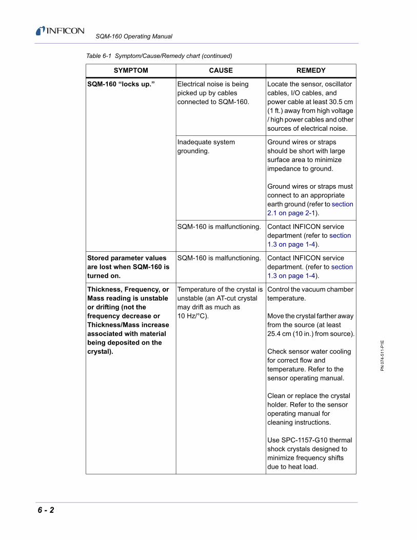
PN
074
-511
-P1E
SQM-160 Operating Manual
SQM-160 “locks up.” Electrical noise is being picked up by cables connected to SQM-160.
Locate the sensor, oscillator cables, I/O cables, and power cable at least 30.5 cm (1 ft.) away from high voltage / high power cables and other sources of electrical noise.
Inadequate system grounding.
Ground wires or straps should be short with large surface area to minimize impedance to ground.
Ground wires or straps must connect to an appropriate earth ground (refer to section 2.1 on page 2-1).
SQM-160 is malfunctioning. Contact INFICON service department (refer to section 1.3 on page 1-4).
Stored parameter values are lost when SQM-160 is turned on.
SQM-160 is malfunctioning. Contact INFICON service department. (refer to section 1.3 on page 1-4).
Thickness, Frequency, or Mass reading is unstable or drifting (not the frequency decrease or Thickness/Mass increase associated with material being deposited on the crystal).
Temperature of the crystal is unstable (an AT-cut crystal may drift as much as 10 Hz/°C).
Control the vacuum chamber temperature.
Move the crystal farther away from the source (at least 25.4 cm (10 in.) from source).
Check sensor water cooling for correct flow and temperature. Refer to the sensor operating manual.
Clean or replace the crystal holder. Refer to the sensor operating manual for cleaning instructions.
Use SPC-1157-G10 thermal shock crystals designed to minimize frequency shifts due to heat load.
Table 6-1 Symptom/Cause/Remedy chart (continued)
SYMPTOM CAUSE REMEDY
6 - 2

PN
074
-511
-P1E
SQM-160 Operating Manual
Thickness, Frequency, or Mass reading is unstable or drifting (not the frequency decrease or Thickness/Mass increase associated with material being deposited on the crystal).
Humidity level on the crystal is changing. Moisture being absorbed or exuded from the crystal surface.
Avoid condensation by turning off cooling water to sensor before opening the vacuum chamber to air, and then flow heated water above the room dew point through the sensor when the chamber is open.
Crystal or crystal holder crystal seating surface scratched or dirty.
Replace crystal.
Clean the crystal seating surface inside the crystal holder or replace crystal holder. Refer to sensor operating manual for cleaning instructions.
Bad sensor/feedthrough, or bad in-vacuum cable, or bad BNC cable.
Use an ohmmeter to check electrical continuity and isolation of sensor/feedthrough, in-vacuum cable, and both BNC cables. Refer to the sensor operating manual for detailed troubleshooting information.
Excessive cable length between oscillator and crystal.
In-vacuum cable length should not exceed 78.1 cm (30.75 in.).
Use the 15.2 cm (6 in.) cable between oscillator and feedthrough.
Table 6-1 Symptom/Cause/Remedy chart (continued)
SYMPTOM CAUSE REMEDY
6 - 3

PN
074
-511
-P1E
SQM-160 Operating Manual
Thickness, Frequency, or Mass reading is unstable or drifting (not the frequency decrease or Thickness/Mass increase associated with material being deposited on the crystal).
SQM-160 or oscillator is malfunctioning.
Test the SQM-160 and oscillator using the oscillator test mode (see section 6.4 on page 6-13).
Substitute a known good SQM-160 (or other QCM).
Substitute a known good oscillator.
Substitute a PN 760-601-G2 Sensor Emulator or a known good sensor for the sensor.
Thickness, Frequency, or Mass reading deviates greatly from the expected value.
Excessive cable length between oscillator and crystal is causing self-oscillation at a frequency different than the crystal frequency.
In-vacuum cable length should not exceed 78.1 cm (30.75 in.).
Use the 15.2 cm (6 in.) cable between oscillator and feedthrough.
Bad sensor/feedthrough, or bad in-vacuum cable, or bad BNC cable.
Use an ohmmeter to check electrical continuity and isolation of sensor/feedthrough, in-vacuum cable, and both BNC cables. Refer to the sensor operating manual for detailed troubleshooting information.
SQM-160 or oscillator is malfunctioning.
Test the SQM-160 and oscillator using the oscillator test mode (see section 6.4 on page 6-13).
Substitute a known good SQM-160 (or other QCM).
Substitute a known good oscillator.
Substitute a PN 760-601-G2 Sensor Emulator or a known good sensor for the sensor.
Table 6-1 Symptom/Cause/Remedy chart (continued)
SYMPTOM CAUSE REMEDY
6 - 4

PN
074
-511
-P1E
SQM-160 Operating Manual
Crystal Status indicator is blinking, indicating Xtal fail.
Failed crystal, or no crystal in sensor.
Install a new crystal.
Two crystals were installed or crystal is upside down.
Remove extra crystal.
Reverse crystal orientation. Inspect crystal for scratches; if scratched, replace with new crystal.
Built-up material at crystal holder aperture is touching the crystal.
Clean or replace the crystal holder. Refer to the sensor operating manual for cleaning instructions.
Crystal frequency is not within the frequency range of SQM-160.
Use a crystal with starting frequency appropriate for SQM-160 frequency range.
Change the FMin/Max frequency settings in SQM-160.
Oscillator/sensor not connected to the Sensor channel corresponding to the blinking Crystal Status indicator.
Connect oscillator/sensor to all active Sensor channels.
Excessive cable length between oscillator and crystal.
In-vacuum cable length should not exceed 78.1 cm (30.75 in.).
Use the 15.2 cm (6 in.) cable between oscillator and feedthrough.
Table 6-1 Symptom/Cause/Remedy chart (continued)
SYMPTOM CAUSE REMEDY
6 - 5

PN
074
-511
-P1E
SQM-160 Operating Manual
Crystal Status indicator is blinking, indicating Xtal fail.
Bad sensor/feedthrough, or bad in-vacuum cable, or bad BNC cable.
Use an ohmmeter to check electrical continuity and isolation of sensor/feedthrough, in-vacuum cable, and both BNC cables. Refer to the sensor operating manual for detailed troubleshooting information.
Substitute known good BNC cables.
Substitute a known good in-vacuum cable.
Substitute a known good sensor/feedthrough.
Substitute a PN 760-601-G2 Sensor Emulator for the sensor.
SQM-160 or oscillator is malfunctioning.
Test the SQM-160 and oscillator using the oscillator test mode (see section 6.4 on page 6-13).
Substitute a known good SQM-160 (or other QCM).
Substitute a known good oscillator.
Substitute a PN 760-601-G2 Sensor Emulator for the sensor.
Table 6-1 Symptom/Cause/Remedy chart (continued)
SYMPTOM CAUSE REMEDY
6 - 6

PN
074
-511
-P1E
SQM-160 Operating Manual
Crystal Status indicator is blinking, indicating Xtal fail, during deposition before “normal” life of crystal is exceeded.
Crystal is being hit by small droplets of molten material from the evaporation source.
Use a shutter to shield the sensor during source conditioning.
Move the crystal farther away (at least 25.4 cm (10 in.)) from the source.
Damaged crystal or deposited material is causing stress to crystal.
Replace the crystal.
Use an Alloy crystal if appropriate for deposited material.
Material buildup on crystal holder is partially masking the crystal surface.
Clean or replace the crystal holder. Refer to the sensor operating manual for cleaning instructions.
Shutter is partially obstructing deposition flux or sensor is poorly positioned, causing uneven distribution of material on crystal.
Visually check crystal for an uneven coating, and if present, correct shutter or sensor positioning problem.
Crystal oscillation is weak due to excessive cable length between oscillator and crystal.
In-vacuum cable length should not exceed 78.1 cm (30.75 in.).
Use the 15.2 cm (6 in.) cable between oscillator and feedthrough.
Crystal Status indicator is blinking, indicating Xtal fail, when vacuum chamber is opened to air.
Crystal was near the end of its life; opening to air causes film oxidation, which increases film stress.
Replace the crystal.
Excessive moisture accumulation on the crystal.
Avoid condensation by turning off cooling water to sensor before opening the vacuum chamber to air, and then flow heated water above the room dew point through the sensor when the chamber is open.
Table 6-1 Symptom/Cause/Remedy chart (continued)
SYMPTOM CAUSE REMEDY
6 - 7

PN
074
-511
-P1E
SQM-160 Operating Manual
Rate reading, and Thickness, Frequency, or Mass reading are noisy.
Excessive cable length between oscillator and crystal.
In-vacuum cable length should not exceed 78.1 cm (30.75 in.).
Use the 15.2 cm (6 in.) cable between oscillator and feedthrough.
Electrical noise is being picked up by cables connected to SQM-160.
Locate the sensor, oscillator cables, I/O cables, communications cable, and power cable at least 30.5 cm (1 ft.) away from high voltage / high power cables and other sources of electrical noise.
Inadequate system grounding.
Ground wires or straps should be short with large surface area to minimize impedance to ground.
Ground wires or straps should connect to an appropriate earth ground (refer to section 2.1 on page 2-1).
Table 6-1 Symptom/Cause/Remedy chart (continued)
SYMPTOM CAUSE REMEDY
6 - 8

PN
074
-511
-P1E
SQM-160 Operating Manual
Thickness, Frequency, or Mass reading has large excursions during deposition.
Mode hopping due to damaged crystal.
Replace the crystal.
Crystal is near the end of its life.
Replace the crystal.
Scratches or foreign particles on the crystal holder crystal seating surface.
Clean the crystal seating surface inside the crystal holder or replace crystal holder. Refer to sensor operating manual for cleaning instructions.
Uneven coating onto crystal. A straight line from center of source to center of crystal should be perpendicular to face of crystal.
Particles on crystal. Replace crystal.
Remove source of particles.
Intermittent cables or connections.
Use an ohmmeter to check electrical continuity / isolation of sensor head, feedthrough, in-vacuum cable, and BNC cables. Refer to the sensor operating manual for detailed troubleshooting information.
Inadequate cooling of crystal. Check water flow rate and temperature for sensor cooling.
Thickness, Frequency, or Mass reading has large excursions during source warm-up or when source shutter is opened (usually causes Thickness reading to decrease) and after the termination of deposition (usually causes Thickness reading to increase).
Crystal not properly seated or crystal holder crystal seating surface is dirty.
Check crystal installation.
Clean the crystal seating surface inside the crystal holder or replace crystal holder. Refer to sensor operating manual for cleaning instructions.
Table 6-1 Symptom/Cause/Remedy chart (continued)
SYMPTOM CAUSE REMEDY
6 - 9

PN
074
-511
-P1E
SQM-160 Operating Manual
Thickness, Frequency, or Mass reading has large excursions during source warm-up or when source shutter is opened (usually causes Thickness reading to decrease) and after the termination of deposition (usually causes Thickness reading to increase).
Excessive heat input to the crystal.
If heat is due to radiation from the evaporation source, move sensor farther away (at least 25.4 cm (10 in.)) from source.
Use SPC-1157-G10 thermal shock crystals designed to minimize frequency shifts due to heat load.
Inadequate cooling of crystal. Check water flow rate and temperature for sensor cooling.
Crystal is being heated by electron flux.
Use a sputtering sensor for non-magnetron sputtering.
Crystal is being hit by small droplets of molten material from the evaporation source.
Use a shutter to shield the sensor during source conditioning.
Move the crystal farther away (at least 25.4 cm (10 in.)) from the source.
Intermittent connection occurring in sensor or feedthrough with thermal variation.
Use an ohmmeter to check electrical continuity / isolation of sensor head, feedthrough, and in-vacuum cable. Refer to the sensor operating manual for detailed troubleshooting information.
Table 6-1 Symptom/Cause/Remedy chart (continued)
SYMPTOM CAUSE REMEDY
6 - 10

PN
074
-511
-P1E
SQM-160 Operating Manual
Thickness reproducibility is poor.
Erratic evaporation flux characteristics.
Move sensor to a different location.
Check the evaporation source for proper operating conditions.
Ensure relatively constant pool height and avoid tunneling into the melt.
Assign multiple sensors to the source.
Material does not adhere well to the crystal.
Check for contamination on the crystal surface.
Evaporate an intermediate layer of appropriate material onto the crystal to improve adhesion.
Use gold, silver, or alloy crystals, as appropriate.
SQM-160 Comm software does not install correctly or does not function correctly.
Host computer has incompatible operating system or incompatible version of operating system.
Check that operating system and version are compatible with SQM-160 Comm software (refer to Chapter 4).
Communication cannot be established between the host computer and SQM-160.
Communications cable is not connected properly to SQM-160 or host computer.
Check cable connections.
Baud setting in SQM-160 is different than the baud setting in SQM-160 Comm software, or the wrong comm port is selected in SQM-160 Comm software.
Correct communications port settings (refer to section 3.5 on page 3-6 and section 4.8 on page 4-17).
SQM-160 Comm software version is not compatible with SQM-160 firmware version.
Contact INFICON technical support (refer to section 1.3 on page 1-4).
RS-232 communication issue.
RS-232 cable is not the correct type.
Use straight-through RS-232 cable (refer to section 5.1.1 on page 5-1).
Table 6-1 Symptom/Cause/Remedy chart (continued)
SYMPTOM CAUSE REMEDY
6 - 11

PN
074
-511
-P1E
SQM-160 Operating Manual
6.2 Maintenance
Routine maintenance is not required for SQM-160. Regular sensor maintenance procedures should be followed according to the sensor operating manual.
6.3 Spare Parts
Fuse . . . . . . . . . . . . . . . . . . . . . . . . . PN 062-0105
Oscillator . . . . . . . . . . . . . . . . . . . . . PN 783-500-013
BNC Cable (15.2 cm (6 in.)) . . . . . . . PN 782-902-011
BNC Cable (3.0 m (10 ft.)) . . . . . . . . PN 782-902-012-10
BNC Cable (7.6 m (25 ft.)) . . . . . . . . PN 782-902-012-25
BNC Cable (15.2 m (50 ft.)) . . . . . . . PN 782-902-012-50
BNC Cable (22.8 m (75 ft.)) . . . . . . . PN 782-902-012-75
USB communication issue. USB device driver is not installed correctly.
Refer to section 5.1.2 on page 5-2.
Ethernet communication issue.
Ethernet network settings in host computer are incorrect.
Refer to section 5.1.3 on page 5-2.
Ethernet IP address setting in SQM-160 Comm software does not match IP address of SQM-160 Ethernet module.
Change Ethernet module IP address or SQM-160 Comm software IP address(refer to section 5.1.3.2 on page 5-8).
Straight-through Ethernet cable is not auto-detected by an older host computer.
Use a cross-over Ethernet cable for a direct connection to a host computer that does not auto-detect cable type.
Table 6-1 Symptom/Cause/Remedy chart (continued)
SYMPTOM CAUSE REMEDY
6 - 12

PN
074
-511
-P1E
SQM-160 Operating Manual
6.4 Persistent Crystal Fail Indication
OSC-100 oscillators have a test feature to help isolate persistent crystal fail problems (see Figure 6-1). To activate the test feature, press the Push to Test button using a small, pointed object, such as a pen or a small screwdriver. This connects the internal test crystal to the circuit instead of the normal Sensor connector. If SQM-160 and the oscillator are functioning correctly, the Crystal Status indicator will stop blinking and illuminate while this button is depressed. Once the Push to Test button is released, the oscillator returns to normal operation and the internal test crystal is no longer in use.
If Crystal Status indicator stops blinking and illuminates while the Push to Test button is depressed, the problem has been isolated to be in the path between the oscillator and the sensor head. If the Crystal Status indicator continues to blink while the Push to Test button is depressed, the problem is either the programming of the sensor selection, in the electronics of the oscillator, or SQM-160.
Figure 6-1 OSC-100 oscillator
6 - 13

PN
074
-511
-P1E
SQM-160 Operating Manual
This page is intentionally blank.
6 - 14

PN
074
-511
-P1E
SQM-160 Operating Manual
Chapter 7Calibration Procedures
7.1 Importance of Density, Tooling and Z-Ratio
The quartz crystal microbalance is capable of precisely measuring the mass added to the face of the oscillating quartz crystal sensor. SQM-160 recognizes the density of this added material to allow conversion of the mass information into thickness. In some instances, where highest accuracy is required, it is necessary to make a density calibration (see section 7.2).
Because the flow of material from a deposition is not uniform, it is necessary to account for the different amount of material flow onto the sensor, compared to the substrates. This is accounted for by the Tooling parameter. Tooling can be experimentally established by following the guidelines in section 7.3 on page 7-2.
If the Z-Ratio is not known, it could be estimated from the procedures,outlined in section 7.4 on page 7-3.
7.2 Determining Density
NOTE: The bulk density values retrieved from Appendix A are sufficiently accurate for most applications.
To determine Density value:
1 Place a substrate (with proper masking for film thickness measurement) adjacent to the sensor, to ensure the same thickness will be accumulated on the crystal and substrate.
2 Set Density to the bulk value of the Film material or to an approximate value.
3 Set Z-Ratio to 1.000 and Tooling to 100%.
4 Place a new crystal in the sensor and make a short deposition (1000 to 5000 Å).
5 After deposition, remove the test substrate and measure the Film thickness with either a multiple beam interferometer or a stylus-type profilometer.
7 - 1

PN
074
-511
-P1E
SQM-160 Operating Manual
6 Determine the new Density value with equation [1]:
[1]
where:
D1 = Initial Density setting
Tx = Thickness reading on SQM-160
Tm = Measured thickness
7 A quick check of the calculated Density may be made. If the SQM-160 thickness has not been zeroed between the test deposition, enter the calculated Density. Program SQM-160 with the new Density value and observe whether the displayed thickness is equal to the measured thickness.
NOTE: Due to variations in source distribution and other system factors, it is recommended that a minimum of three separate evaporations be made, to obtain an average value for Density.
NOTE: Slight adjustment of Density may be necessary, in order to achieve Tx = Tm.
7.3 Determining Tooling
1 Place a test substrate in the system substrate holder.
2 Make a short deposition and determine actual thickness.
3 Calculate Tooling from the relationship in equation [2]:
[2]
where
Tm = Actual thickness at substrate holder
Tx = Thickness reading in SQM-160
TFi = Initial Tooling factor
4 Round percent tooling to the nearest 1%.
5 When entering this new value for Tooling into the program, if calculations are done properly, Tm will equal Tx.
NOTE: To account for variations in source distribution and other system factors, obtain an average value for Tooling, using a minimum of three separate evaporations.
Density g cm3 D1
Tx
Tm-------
=
Tooling (%) TFi
Tm
Tx-------
=
7 - 2

PN
074
-511
-P1E
SQM-160 Operating Manual
7.4 Laboratory Determination of Z-Ratio
A list of Z-Ratio values for materials commonly used are available in Appendix A. For other materials, Z-Ratio can be calculated from the following formula:
[3]
[4]
where:
df = Density (g/cm3) of deposited film
µf = Shear modulus (dynes/cm2) of deposited film
dq = Density of quartz (crystal) (2.649 g/cm3)
µq = Shear modulus of quartz (crystal) (3.32 x 10¹¹ dynes/cm2)
NOTE: The densities and shear moduli of many materials can be found in a number of handbooks.
Laboratory results indicate that Z-Ratio of materials in thin-film form are very close to the bulk values; however, for high stress producing materials, Z-Ratio values of thin films are slightly smaller than those of the bulk materials. For applications that require more precise calibration, the following direct method is suggested:
1 Establish the correct density value as described in section 7.2 on page 7-1.
2 Install a new crystal and record its starting Frequency, Fco.
3 Make a deposition on a test substrate such that the percent Crystal Life display will read approximately 50%, or near the end of crystal life for the particular material, whichever is smaller.
4 Stop the deposition and record the ending crystal Frequency Fc.
5 Remove the test substrate and measure the film thickness with either a multiple beam interferometer or a stylus-type profilometer.
Zdqq
dff------------
12---
=
Z 9.378 105
dff -12---
=
7 - 3

PN
074
-511
-P1E
SQM-160 Operating Manual
6 Using the Density value from step 1 and the recorded values for Fco and Fc, adjust the Z-Ratio value in thickness equation [5] to bring the calculated thickness value into agreement with the actual thickness.
If the calculated value of thickness is greater than the actual thickness, increase the Z-Ratio value.
If the calculated value of thickness is less than the actual thickness, decrease the Z-Ratio value.
[5]
where:
Tf = Thickness of deposited film (kÅ)
Fco = Starting frequency of the sensor crystal (Hz)
Fc = Final frequency of the sensor crystal (Hz)
Fq = Nominal blank frequency = 6045000 (Hz)
z = Z-Ratio of deposited film material
Zq = Specific acoustic impedance of quartz = 8765000 (kg/(m2*s))
p = Density of deposited film (g/cm3)
For multiple layer deposition (for example, two layers), the Z-Ratio used for the second layer is determined by the relative thickness of the two layers. For most applications, the following three rules will provide reasonable accuracies:
If the thickness of layer 1 is large compared to layer 2, use material 1 Z-Ratio for both layers.
If the thickness of layer 1 is thin compared to layer 2, use material 2 Z-Ratio for both layers.
If the thickness of both layers is similar, use a value for Z-Ratio which is the weighted average of the two Z-Ratio values for deposition of layer 2 and subsequent layers.
Tf
Zq 104
2zp-------------------- 1
Fco-------- ATan zTan
Fco
Fq-----------
1
Fc----- ATan zTan
Fc
Fq---------
–
=
7 - 4

PN
074
-511
-P1E
SQM-160 Operating Manual
Chapter 8Measurement and Theory
8.1 Basics
The Quartz Crystal deposition Monitor (QCM) utilizes the piezoelectric sensitivity of a quartz monitor crystal to added mass. The QCM uses this mass sensitivity to control the deposition rate and final thickness of a vacuum deposition.
When a voltage is applied across the faces of a properly shaped piezoelectric crystal, the crystal is distorted and changes shape in proportion to the applied voltage. At certain discrete frequencies of applied voltage, a condition of sharp electro-mechanical resonance is encountered.
When mass is added to the face of a resonating quartz crystal, the frequency of these resonances are reduced. This change in frequency is very repeatable and is precisely understood for specific oscillating modes of quartz. This phenomenon is the basis of an indispensable measurement and process control tool that can easily detect the addition of less than an atomic layer of an adhered foreign material.
In the late 1950’s it was noted by Sauerbrey1,2 and Lostis3 that the change in frequency, DF = Fq-Fc, of a quartz crystal with coated (or composite) and uncoated frequencies, Fc and Fq respectively, is related to the change in mass from the added material, Mf , as follows:
[1]
where Mq is the mass of the uncoated quartz crystal. Simple substitutions lead to the equation used with the first frequency measurement instruments:
[2]
where the film thickness, Tf, is proportional (through K) to the frequency change, DF, and inversely proportional to the density of the film, df. The constant, K = Natdq/Fq
2; where dq (= 2.649 g/cm3) is the density of single crystal quartz and Nat (=166100 Hz cm) is the frequency constant of AT cut quartz.
1.G. Z. Sauerbrey, Phys. Verhand .8, 193 (1957)2.G. Z. Sauerbrey, Z. Phys. 155,206 (1959)3.P. Lostis, Rev. Opt. 38,1 (1959)
Mf
Mq------- F
Fq-----------=
TfK F
df----------------=
8 - 1

PN
074
-511
-P1E
SQM-160 Operating Manual
A crystal with a starting frequency of 6.0 MHz will display a reduction of its frequency by 2.27 Hz when 1 angstrom of Aluminum (density of 2.77 g/cm3) is added to its surface. In this manner, the thickness of a rigid adlayer is inferred from the precise measurement of the frequency shift of the crystal.
The quantitative knowledge of this effect provides a means of determining how much material is being deposited on a substrate in a vacuum system, a measurement that was not convenient or practical prior to this understanding.
8.1.1 Monitor Crystals
No matter how sophisticated the electronics surrounding it, the essential device of the deposition monitor is the quartz crystal. The quartz crystal in Figure 8-1 has a frequency response spectrum that is schematically displayed in Figure 8-2. The ordinate represents the magnitude of response, or current flow of the crystal, at the specified frequency.
Figure 8-1 Quartz resonator
The lowest frequency response is primarily a thickness shear mode that is called the fundamental. The characteristic movement of the thickness shear mode is for displacement to take place parallel to the major monitor crystal faces. In other words, the faces are displacement antinodes (see Figure 8-3).
The responses located slightly higher in frequency are called anharmonics; they are a combination of the thickness shear and thickness twist modes. The response at about three times the frequency of the fundamental is called the third quasiharmonic. There are also a series of anharmonics slightly higher in frequency associated with the quasiharmonic.
The monitor crystal design depicted in Figure 8-1 is the result of several significant improvements from the square crystals, with fully electroded plane parallel faces that were first used.
The first improvement implemented the use of circular crystals. The resulting increase in symmetry greatly reduces the number of allowed vibrational modes.
1.4 cm (0.55 in.)
R
+
8 - 2

PN
074
-511
-P1E
SQM-160 Operating Manual
The second set of improvements was to contour one face of the crystal and to reduce the size of the exciting electrode. These improvements have the effect of trapping the acoustic energy.
Reducing the electrode diameter limits the excitation to the central area. Contouring dissipates the energy of the traveling acoustic wave before it reaches the edge of the crystal. Energy is not reflected back to the center where it can interfere with other newly launched waves, essentially making a small crystal appear to behave as though it is infinite in extent.
With the crystal vibrations restricted to the center, it is practical to clamp the outer edges of the crystal to a holder, and not produce any undesirable effects. Contouring also reduces the intensity of response of the generally unwanted anharmonic modes; hence, the potential for an oscillator to sustain an unwanted oscillation is substantially reduced.
Figure 8-2 Frequency response spectrum
The use of an adhesion layer has improved the electrode-to-quartz bonding, reducing rate spikes caused by micro-tears between the electrode and the quartz, as film stress rises. These micro-tears leave portions of the deposited film unattached, and therefore unable to participate in the oscillation. These free portions are no longer detected, which prevents the consequential wrong thickness from being inferred.
The AT resonator is usually chosen for deposition monitoring, because at room temperature it can be made to exhibit a very small frequency change, due to temperature changes.
5.98
1 M
Hz
15 o
hm
6.15
3 M
Hz
50 o
hm6.
194
MH
z 40
ohm
6.33
3 M
Hz
142
ohm
6.33
7 M
Hz
105
ohm
6.34
8 M
Hz
322
ohm
6.41
9 M
Hz
350
ohm
17.7
92 M
Hz
278
ohm
17.9
57 M
Hz
311
ohm
18.1
33 M
Hz
350
ohm
Lo
g o
f re
lati
ve i
nte
ns
ity
(Ad
mit
tan
ce)
Frequency (in MHz)
110
1100
11000
6 7 17 18
8 - 3
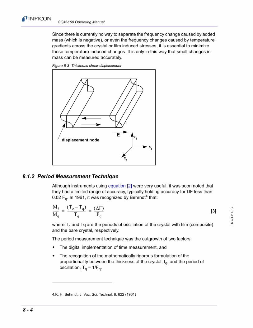
PN
074
-511
-P1E
SQM-160 Operating Manual
Since there is currently no way to separate the frequency change caused by added mass (which is negative), or even the frequency changes caused by temperature gradients across the crystal or film induced stresses, it is essential to minimize these temperature-induced changes. It is only in this way that small changes in mass can be measured accurately.
Figure 8-3 Thickness shear displacement
8.1.2 Period Measurement Technique
Although instruments using equation [2] were very useful, it was soon noted that they had a limited range of accuracy, typically holding accuracy for DF less than 0.02 Fq. In 1961, it was recognized by Behrndt4 that:
[3]
where Tc and Tq are the periods of oscillation of the crystal with film (composite) and the bare crystal, respectively.
The period measurement technique was the outgrowth of two factors:
The digital implementation of time measurement, and
The recognition of the mathematically rigorous formulation of the proportionality between the thickness of the crystal, Iq, and the period of oscillation, Tq = 1/Fq.
displacement nodeX
X
X
2
1
3
E
4.K. H. Behrndt, J. Vac. Sci. Technol. 8, 622 (1961)
Mf
Mq-------
Tc Tq– Tq
---------------------- F Fc
-----------= =
8 - 4

PN
074
-511
-P1E
SQM-160 Operating Manual
Electronically, the period measurement technique uses a second crystal oscillator, or reference oscillator, not affected by the deposition, which is usually much higher in frequency than the monitor crystal. This reference oscillator is used to generate small precision time intervals, which are used to determine the oscillation period of the monitor crystal. This is done by using two pulse accumulators:
The first is used to accumulate a fixed number of cycles, m, of the monitor crystal.
The second is turned on at the same time and accumulates cycles from the reference oscillator until m counts are accumulated in the first.
Since the frequency of the reference is stable and known, the time to accumulate the m counts is known to an accuracy equal to ±2/Fr where Fr is the reference oscillator frequency.
The period of the monitor crystal is (n/Fr)/m, where n is the number of counts in the second accumulator. The precision of the measurement is determined by the speed of the reference clock and the length of the gate time (set by the size of m). Increasing one or both of these leads to improved measurement precision.
Having a high frequency reference oscillator is important for rapid measurements (which require short gating times), low deposition rates, and low density materials. All of these require high time precision to resolve the small, mass-induced frequency shifts between measurements.
When the change of a monitor crystal frequency between measurements is small, that is, on the same order of size as the measurement precision, it is not possible to establish quality rate control. The uncertainty of the measurement injectsmore noise into the control loop, which can be counteracted only by longer time constants. Long time constants cause the correction of rate errors to be very slow, resulting in relatively long term deviations from the desired rate.
These deviations may not be important for some simple films, but can cause unacceptable errors in the production of critical films such as optical filters or very thin-layered superlattices grown at low rates.
In many cases, the desired properties of these films can be lost if the layer-to-layer reproducibility exceeds one, or two, percent. Ultimately, the practical stability and frequency of the reference oscillator limits the precision of measurement for conventional instrumentation.
8 - 5

PN
074
-511
-P1E
SQM-160 Operating Manual
8.1.3 Z-match Technique
After learning of fundamental work by Miller and Bolef 5, which rigorously treated the resonating quartz and deposited film system as a one-dimensional continuous acoustic resonator, Lu and Lewis6 developed the simplifying Z-match™ equation in 1972. Advances in electronics taking place at the same time, namely the micro-processor, made it practical to solve the Z-match equation in real-time.
Most deposition process controllers/monitors sold today use this sophisticated equation that takes into account the acoustic properties of the resonating quartz and film system (see equation [4]).
[4]
where Z=(dquq/dfuf)1/2 is the acoustic impedance ratio and uq and uf are the shear
moduli of the quartz and film, respectively.
Finally, there was a fundamental understanding of the frequency-to-thickness conversion that could yield theoretically correct results in a time frame that was practical for process control.
To achieve this new level of accuracy requires only that the user enter an additional material parameter, Z, for the film being deposited. This equation has been tested for a number of materials, and has been found to be valid for frequency shifts equivalent to Ff = 0.4Fq.
Keep in mind that equation [2] was valid to only 0.02Fq and equation [3] was valid only to ~0.05Fq.
5.J. G. Miller and D. I. Bolef, J. Appl. Phys. 39, 5815, 4589 (1968)6.C. Lu and O. Lewis, J Appl. Phys. 43, 4385 (1972)
Tf
Natdq
dfFcZ------------------ arctan Z tan
Fq Fc– Fq
------------------------- =
8 - 6

PN
074
-511
-P1E
SQM-160 Operating Manual
Appendix AMaterial Table
A.1 Introduction
The following Table A-1 represents the density and Z-Ratio for various materials. The list is alphabetical, by chemical formula.
WARNING
Some of these materials are toxic. Consult the material safety data sheet and safety instructions before use.
An * is used to indicate that a Z-Ratio has not been established for a certain material. A value of 1.000 is defaulted in these situations.
Table A-1 Material table
Formula Density Z-Ratio Material Name
Ag 10.500 0.529 silver
AgBr 6.470 1.180 silver bromide
AgCl 5.560 1.320 silver chloride
Al 2.700 1.080 aluminum
Al2O3 3.970 0.336 aluminum oxide
Al4C3 2.360 *1.000 aluminum carbide
AIF3 3.070 *1.000 aluminum fluoride
AIN 3.260 *1.000 aluminum nitride
AlSb 4.360 0.743 aluminum antimonide
As 5.730 0.966 arsenic
As2Se3 4.750 *1.000 arsenic selenide
Au 19.300 0.381 gold
B 2.370 0.389 boron
B203 1.820 *1.000 boron oxide
B4C 2.370 *1.000 boron carbide
BN 1.860 *1.000 boron nitride
Ba 3.500 2.100 barium
BaF2 4.886 0.793 barium fluoride
BaN2O6 3.244 1.261 barium nitrate
A - 1

PN
074
-511
-P1E
SQM-160 Operating Manual
BaO 5.720 *1.000 barium oxide
BaTiO3 5.999 0.464 barium titanate (tetr)
BaTiO3 6.035 0.412 barium titanate (cubic)
Be 1.850 0.543 beryllium
BeF2 1.990 *1.000 beryllium fluoride
BeO 3.010 *1.000 beryllium oxide
Bi 9.800 0.790 bismuth
Bi2O3 8.900 *1.000 bismuth oxide
Bi2S3 7.390 *1.000 bismuth trisulfide
Bi2Se3 6.820 *1.000 bismuth selenide
Bi2Te3 7.700 *1.000 bismuth telluride
BiF3 5.320 *1.000 bismuth fluoride
C 2.250 3.260 carbon (graphite)
C 3.520 0.220 carbon (diamond)
C8H8 1.100 *1.000 parlyene (union carbide)
Ca 1.550 2.620 calcium
CaF2 3.180 0.775 calcium fluoride
CaO 3.350 *1.000 calcium oxide
CaO-SiO2 2.900 *1.000 calcium silicate (3)
CaSO4 2.962 0.955 calcium sulfate
CaTiO3 4.100 *1.000 calcium titanate
CaWO4 6.060 *1.000 calcium tungstate
Cd 8.640 0.682 cadmium
CdF2 6.640 *1.000 cadmium fluoride
CdO 8.150 *1.000 cadmium oxide
CdS 4.830 1.020 cadmium sulfide
CdSe 5.810 *1.000 cadmium selenide
CdTe 6.200 0.980 cadmium telluride
Ce 6.780 *1.000 cerium
CeF3 6.160 *1.000 cerium (iii) fluoride
CeO2 7.130 *1.000 cerium (iv) dioxide
Co 8.900 0.343 cobalt
CoO 6.440 0.412 cobalt oxide
Table A-1 Material table (continued)
Formula Density Z-Ratio Material Name
A - 2

PN
074
-511
-P1E
SQM-160 Operating Manual
Cr 7.200 0.305 chromium
Cr2O3 5.210 *1.000 chromium (iii) oxide
Cr3C2 6.680 *1.000 chromium carbide
CrB 6.170 *1.000 chromium boride
Cs 1.870 *1.000 cesium
Cs2SO4 4.243 1.212 cesium sulfate
CsBr 4.456 1.410 cesium bromide
CsCI 3.988 1.399 cesium chloride
CsI 4.516 1.542 cesium iodide
Cu 8.930 0.437 copper
Cu2O 6.000 *1.000 copper oxide
Cu2S 5.600 0.690 copper (i) sulfide (alpha)
Cu2S 5.800 0.670 copper (i) sulfide (beta)
CuS 4.600 0.820 copper (ii) sulfide
Dy 8.550 0.600 dysprosium
DY2O3 7.810 *1.000 dysprosium oxide
Er 9.050 0.740 erbium
Er2O3 8.640 *1.000 erbium oxide
Eu 5.260 *1.000 europium
EuF2 6.500 *1.000 europium fluoride
Fe 7.860 0.349 iron
Fe2O3 5.240 *1.000 iron oxide
FeO 5.700 *1.000 iron oxide
FeS 4.840 *1.000 iron sulfide
Ga 5.930 0.593 gallium
Ga2O3 5.880 *1.000 gallium oxide (b)
GaAs 5.310 1.590 gallium arsenide
GaN 6.100 *1.000 gallium nitride
GaP 4.100 *1.000 gallium phosphide
GaSb 5.600 *1.000 gallium antimonide
Gd 7.890 0.670 gadolinium
Gd2O3 7.410 *1.000 gadolinium oxide
Ge 5.350 0.516 germanium
Table A-1 Material table (continued)
Formula Density Z-Ratio Material Name
A - 3

PN
074
-511
-P1E
SQM-160 Operating Manual
Ge3N2 5.200 *1.000 germanium nitride
GeO2 6.240 *1.000 germanium oxide
GeTe 6.200 *1.000 germanium telluride
Hf 13.090 0.360 hafnium
HfB2 10.500 *1.000 hafnium boride
HfC 12.200 *1.000 hafnium carbide
HfN 13.800 *1.000 hafnium nitride
HfO2 9.680 *1.000 hafnium oxide
HfSi2 7.200 *1.000 hafnium silicide
Hg 13.460 0.740 mercury
Ho 8.800 0.580 holmium
Ho2O3 8.410 *1.000 holmium oxide
In 7.300 0.841 indium
In2O3 7.180 *1.000 indium sesquioxide
In2Se3 5.700 *1.000 indium selenide
In2Te3 5.800 *1.000 indium telluride
InAs 5.700 *1.000 indium arsenide
InP 4.800 *1.000 indium phosphide
InSb 5.760 0.769 indium antimonide
Ir 22.400 0.129 iridium
K 0.860 10.189 potassium
KBr 2.750 1.893 potassium bromide
KCI 1.980 2.050 potassium chloride
KF 2.480 *1.000 potassium fluoride
KI 3.128 2.077 potassium iodide
La 6.170 0.920 lanthanum
La2O3 6.510 *1.000 lanthanum oxide
LaB6 2.610 *1.000 lanthanum boride
LaF3 5.940 *1.000 lanthanum fluoride
Li 0.530 5.900 lithium
LiBr 3.470 1.230 lithium bromide
LiF 2.638 0.778 lithium fluoride
LiNbO3 4.700 0.463 lithium niobate
Table A-1 Material table (continued)
Formula Density Z-Ratio Material Name
A - 4

PN
074
-511
-P1E
SQM-160 Operating Manual
Lu 9.840 *1.000 lutetium
Mg 1.740 1.610 magnesium
MgAl2O4 3.600 *1.000 magnesium aluminate
MgAl2O6 8.000 *1.000 spinel
MgF2 3.180 0.637 magnesium fluoride
MgO 3.580 0.411 magnesium oxide
Mn 7.200 0.377 manganese
MnO 5.390 0.467 manganese oxide
MnS 3.990 0.940 manganese (ii) sulfide
Mo 10.200 0.257 molybdenum
Mo2C 9.180 *1.000 molybdenum carbide
MoB2 7.120 *1.000 molybdenum boride
MoO3 4.700 *1.000 molybdenum trioxide
MoS2 4.800 *1.000 molybdenum disulfide
Na 0.970 4.800 sodium
Na3AIF6 2.900 *1.000 cryolite
Na5Al3F14 2.900 *1.000 chiolite
NaBr 3.200 *1.000 sodium bromide
NaCl 2.170 1.570 sodium chloride
NaCIO3 2.164 1.565 sodium chlorate
NaF 2.558 1.645 sodium fluoride
NaNO3 2.270 1.194 sodium nitrate
Nb 8.578 0.492 niobium (columbium)
Nb2O3 7.500 *1.000 niobium trioxide
Nb2O5 4.470 *1.000 niobium (v) oxide
NbB2 6.970 *1.000 niobium boride
NbC 7.820 *1.000 niobium carbide
NbN 8.400 *1.000 niobium nitride
Nd 7.000 *1.000 neodymium
Nd2O3 7.240 *1.000 neodymium oxide
NdF3 6.506 *1.000 neodymium fluoride
Ni 8.910 0.331 nickel
NiCr 8.500 *1.000 nichrome
Table A-1 Material table (continued)
Formula Density Z-Ratio Material Name
A - 5

PN
074
-511
-P1E
SQM-160 Operating Manual
NiCrFe 8.500 *1.000 Inconel
NiFe 8.700 *1.000 permalloy
NiFeMo 8.900 *1.000 supermalloy
NiO 7.450 *1.000 nickel oxide
P3N5 2.510 *1.000 phosphorus nitride
Pb 11.300 1.130 lead
PbCl2 5.850 *1.000 lead chloride
PbF2 8.240 0.661 lead fluoride
PbO 9.530 *1.000 lead oxide
PbS 7.500 0.566 lead sulfide
PbSe 8.100 *1.000 lead selenide
PbSnO3 8.100 *1.000 lead stannate
PbTe 8.160 0.651 lead telluride
Pd 12.038 0.357 palladium
PdO 8.310 *1.000 palladium oxide
Po 9.400 *1.000 polonium
Pr 6.780 *1.000 praseodymium
Pr2O3 6.880 *1.000 praseodymium oxide
Pt 21.400 0.245 platinum
PtO2 10.200 *1.000 platinum oxide
Ra 5.000 *1.000 radium
Rb 1.530 2.540 rubidium
RbI 3.550 *1.000 rubidium iodide
Re 21.040 0.150 rhenium
Rh 12.410 0.210 rhodium
Ru 12.362 0.182 ruthenium
S8 2.070 2.290 sulfur
Sb 6.620 0.768 antimony
Sb2O3 5.200 *1.000 antimony trioxide
Sb2S3 4.640 *1.000 antimony trisulfide
Sc 3.000 0.910 scandium
Sc2O3 3.860 *1.000 scandium oxide
Se 4.810 0.864 selenium
Table A-1 Material table (continued)
Formula Density Z-Ratio Material Name
A - 6

PN
074
-511
-P1E
SQM-160 Operating Manual
Si 2.320 0.712 silicon
Si3N4 3.440 *1.000 silicon nitride
SiC 3.220 *1.000 silicon carbide
SiO 2.130 0.870 silicon (ii) oxide
SiO2 2.648 1.000 silicon dioxide
Sm 7.540 0.890 samarium
Sm2O3 7.430 *1.000 samarium oxide
Sn 7.300 0.724 tin
SnO2 6.950 *1.000 tin oxide
SnS 5.080 *1.000 tin sulfide
SnSe 6.180 *1.000 tin selenide
SnTe 6.440 *1.000 tin telluride
Sr 2.600 *1.000 strontium
SrF2 4.277 0.727 strontium fluoride
SrO 4.990 0.517 strontium oxide
Ta 16.600 0.262 tantalum
Ta2O5 8.200 0.300 tantalum (v) oxide
TaB2 11.150 *1.000 tantalum boride
TaC 13.900 *1.000 tantalum carbide
TaN 16.300 *1.000 tantalum nitride
Tb 8.270 0.660 terbium
Tc 11.500 *1.000 technetium
Te 6.250 0.900 tellurium
TeO2 5.990 0.862 tellurium oxide
Th 11.694 0.484 thorium
ThF4 6.320 *1.000 thorium (iv) fluoride
ThO2 9.860 0.284 thorium dioxide
ThOF2 9.100 *1.000 thorium oxyfluoride
Ti 4.500 0.628 titanium
Ti203 4.600 *1.000 titanium sesquioxide
TiB2 4.500 *1.000 titanium boride
TiC 4.930 *1.000 titanium carbide
TiN 5.430 *1.000 titanium nitride
Table A-1 Material table (continued)
Formula Density Z-Ratio Material Name
A - 7
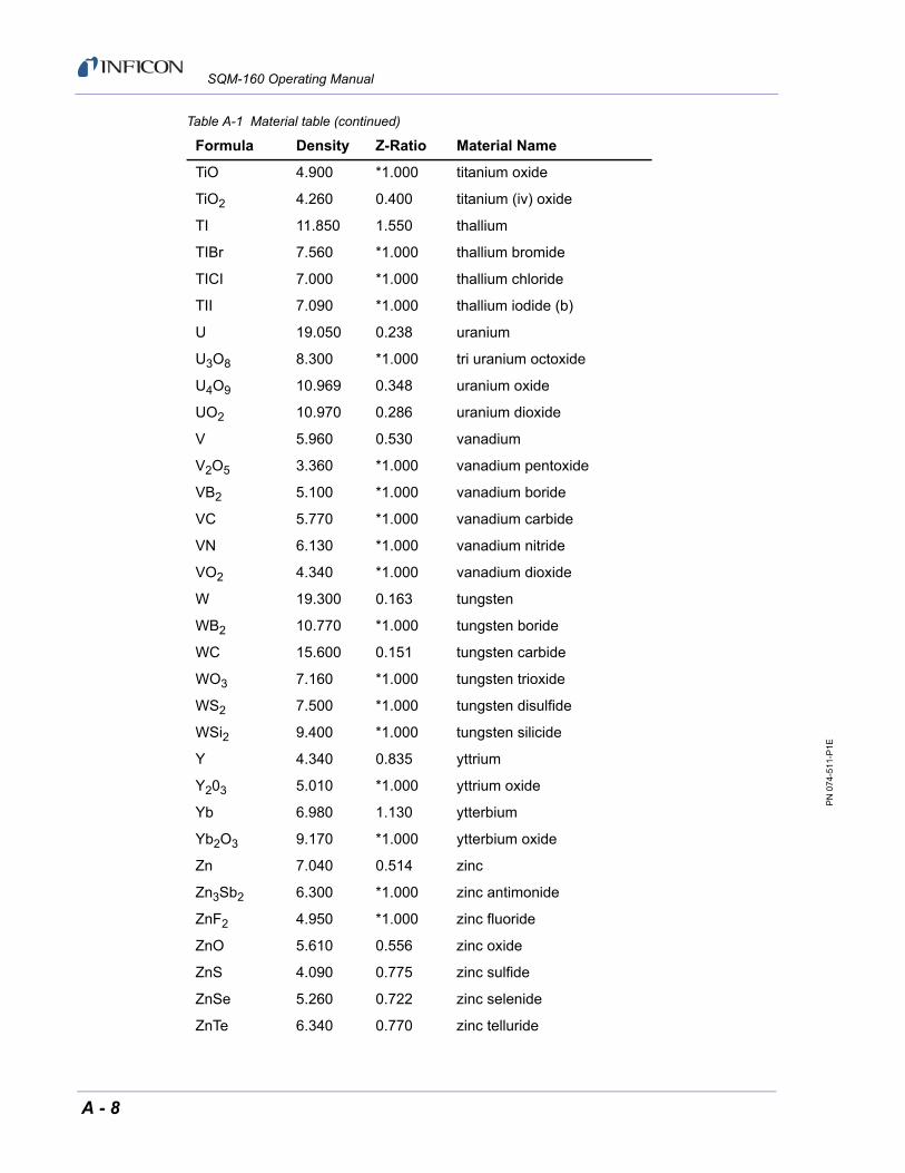
PN
074
-511
-P1E
SQM-160 Operating Manual
TiO 4.900 *1.000 titanium oxide
TiO2 4.260 0.400 titanium (iv) oxide
TI 11.850 1.550 thallium
TIBr 7.560 *1.000 thallium bromide
TICI 7.000 *1.000 thallium chloride
TII 7.090 *1.000 thallium iodide (b)
U 19.050 0.238 uranium
U3O8 8.300 *1.000 tri uranium octoxide
U4O9 10.969 0.348 uranium oxide
UO2 10.970 0.286 uranium dioxide
V 5.960 0.530 vanadium
V2O5 3.360 *1.000 vanadium pentoxide
VB2 5.100 *1.000 vanadium boride
VC 5.770 *1.000 vanadium carbide
VN 6.130 *1.000 vanadium nitride
VO2 4.340 *1.000 vanadium dioxide
W 19.300 0.163 tungsten
WB2 10.770 *1.000 tungsten boride
WC 15.600 0.151 tungsten carbide
WO3 7.160 *1.000 tungsten trioxide
WS2 7.500 *1.000 tungsten disulfide
WSi2 9.400 *1.000 tungsten silicide
Y 4.340 0.835 yttrium
Y203 5.010 *1.000 yttrium oxide
Yb 6.980 1.130 ytterbium
Yb2O3 9.170 *1.000 ytterbium oxide
Zn 7.040 0.514 zinc
Zn3Sb2 6.300 *1.000 zinc antimonide
ZnF2 4.950 *1.000 zinc fluoride
ZnO 5.610 0.556 zinc oxide
ZnS 4.090 0.775 zinc sulfide
ZnSe 5.260 0.722 zinc selenide
ZnTe 6.340 0.770 zinc telluride
Table A-1 Material table (continued)
Formula Density Z-Ratio Material Name
A - 8

PN
074
-511
-P1E
SQM-160 Operating Manual
Zr 6.490 0.600 zirconium
ZrB2 6.080 *1.000 zirconium boride
ZrC 6.730 0.264 zirconium carbide
ZrN 7.090 *1.000 zirconium nitride
ZrO2 5.600 *1.000 zirconium oxide
Table A-1 Material table (continued)
Formula Density Z-Ratio Material Name
A - 9

PN
074
-511
-P1E
SQM-160 Operating Manual
This page is intentionally blank.
A - 10