OpenScope MZ Reference Manual - robotshop.com · OpenScope MZ. The host computer will need a USB...
20
2/10/2018 OpenScope MZ Reference Manual [Reference.Digilentinc] https://reference.digilentinc.com/reference/instrumentation/openscope-mz/reference-manual 1/20 OpenScope MZ is an open source, multi-function, electronic instrumentation device that can be controlled using a computer or mobile device to acquire, analyze, visualize, and generate signals from circuits, sensors, and other electronic devices. OpenScope MZ makes it easy to generate analog and digital signals using the power supply, function generator and GPIO () and measure and visualize analog and digital signals using the oscilloscope and logic analyzer. Develop and debug circuits faster by generating stimuli and visualizing the response using OpenScope MZ. OpenScope MZ Reference Manual
Transcript of OpenScope MZ Reference Manual - robotshop.com · OpenScope MZ. The host computer will need a USB...

2/10/2018 OpenScope MZ Reference Manual [Reference.Digilentinc]
https://reference.digilentinc.com/reference/instrumentation/openscope-mz/reference-manual 1/20
OpenScope MZ is an open source, multi-function, electronic instrumentation device that can be controlled using a computer or mobiledevice to acquire, analyze, visualize, and generate signals from circuits, sensors, and other electronic devices. OpenScope MZ makes it easyto generate analog and digital signals using the power supply, function generator and GPIO () and measure and visualize analog and digitalsignals using the oscilloscope and logic analyzer. Develop and debug circuits faster by generating stimuli and visualizing the response usingOpenScope MZ.
OpenScope MZ Reference Manual

2/10/2018 OpenScope MZ Reference Manual [Reference.Digilentinc]
https://reference.digilentinc.com/reference/instrumentation/openscope-mz/reference-manual 2/20
(https://reference.digilentinc.com/_media/reference/instrumentation/openscope-mz/openscope_mz_5.png)

2/10/2018 OpenScope MZ Reference Manual [Reference.Digilentinc]
https://reference.digilentinc.com/reference/instrumentation/openscope-mz/reference-manual 3/20
2/10/2018 OpenScope MZ Reference Manual [Reference.Digilentinc]
https://reference.digilentinc.com/reference/instrumentation/openscope-mz/reference-manual 4/20

2/10/2018 OpenScope MZ Reference Manual [Reference.Digilentinc]
https://reference.digilentinc.com/reference/instrumentation/openscope-mz/reference-manual 5/20

2/10/2018 OpenScope MZ Reference Manual [Reference.Digilentinc]
https://reference.digilentinc.com/reference/instrumentation/openscope-mz/reference-manual 6/20

2/10/2018 OpenScope MZ Reference Manual [Reference.Digilentinc]
https://reference.digilentinc.com/reference/instrumentation/openscope-mz/reference-manual 7/20

2/10/2018 OpenScope MZ Reference Manual [Reference.Digilentinc]
https://reference.digilentinc.com/reference/instrumentation/openscope-mz/reference-manual 8/20

2/10/2018 OpenScope MZ Reference Manual [Reference.Digilentinc]
https://reference.digilentinc.com/reference/instrumentation/openscope-mz/reference-manual 9/20

2/10/2018 OpenScope MZ Reference Manual [Reference.Digilentinc]
https://reference.digilentinc.com/reference/instrumentation/openscope-mz/reference-manual 10/20
ConnectivityWiFi (802.11g)USB 2.0 (High Speed Required)
Oscilloscope2 Channels12-bit resolution per channel6.25 MS/s () sample rateFlat bandwidth up to 1 MHz () at ±0.5dB2 MHz () of bandwidth at -3dB1 MΩ of input impedance±20 V input voltage rangeMaximum buffer size of 32640 samples per channel
Arbitrary Waveform GeneratorSine, triangle, sawtooth, square and DC outputs10-bit resolution1 Hz () to 1 MHz () frequency3 V pk2pk output with ±1.5 V offset10 mA output current25000 sample buffer size
Logic Analyzer and GPIO ()10 Channels multiplexed between the Logic Analyzer and as general purpose IO3.3V CMOS logic for both the Logic Analyzer and GPIO ()7 mA source and 12 mA sink when used as GPIO ()Logic Analyzer has a sample rate of 10 MS/s ()Maximum buffer size of 32640 samples per channel for the Logic Analyzer
Power Supply2 Channels±4 V output voltage50 mA per channel
Other featuresTwo external triggersUSB powered device4 user LEDs
PIC32MZ2048EFG124 microcontroller
Features

2/10/2018 OpenScope MZ Reference Manual [Reference.Digilentinc]
https://reference.digilentinc.com/reference/instrumentation/openscope-mz/reference-manual 11/20
(https://reference.digilentinc.com/_detail/reference/instrumentation/openscope-mz/openscope_mz_hardware_block_diagram.png?id=reference%3Ainstrumentation%3Aopenscope-mz%3Areference-manual)
(https://reference.digilentinc.com/_detail/reference/instrumentation/openscope-mz/pinout_diagram.png?id=reference%3Ainstrumentation%3Aopenscope-mz%3Areference-manual)
OpenScope MZ J1 Header Pinout
Top Row Bottom Row
1 D8 (8) 2 UART_RX/PWM2 (P5)
3 D7 (7) 4 SPI_CS ()/UART_RTS/PWM1 (P4)
5 D6 (6) 6 SPI_CLK/UART_CTS (P3)

2/10/2018 OpenScope MZ Reference Manual [Reference.Digilentinc]
https://reference.digilentinc.com/reference/instrumentation/openscope-mz/reference-manual 12/20
OpenScope MZ J1 Header Pinout
Top Row Bottom Row
7 D5 (5) 8 SDI/SDO/UART_TX (P2)
9 D4 (4) 10 SDI/SDO (P1)
11 D3 (3) 12 INT ()/CLK2 (C2)
13 D2 (2) 14 DO10 (10)
15 D1 (1) 16 DO9 (9)
17 Trigger Input (T1) 18 Trigger Output (T0)
19 GND () (↓) 20 GND () (↓)
21 AWG1 (W1) 22 INT ()/CLK1 (C1)
23 DC Output 1 (V1) 24 DC Output 2 (V2)
25 GND () (↓) 26 GND () (↓)
27 AI2+/OSC2 (2+) 28 GND ()/AI2- (2-)
29 AI1+/OSC1 (1+) 30 GND ()/AI1- (1-)
(https://reference.digilentinc.com/_detail/reference/instrumentation/openscope-mz/openscopemz_walk_around.png?id=reference%3Ainstrumentation%3Aopenscope-mz%3Areference-manual)
OpenScope MZ uses the ADC () on the PIC32MZ to create a 2 channel oscilloscope with 12-bits of resolution per channel. Each channelhas a pair of analog inputs with a PWM output to facilitate the interleaving of the two inputs, one PWM to handle the input offset voltages,and one DMA channel at the second highest priority to transfer the measured data.
Walk Around the Board
Oscilloscope

2/10/2018 OpenScope MZ Reference Manual [Reference.Digilentinc]
https://reference.digilentinc.com/reference/instrumentation/openscope-mz/reference-manual 13/20
(https://reference.digilentinc.com/_detail/reference/instrumentation/openscope-mz/analog_input_schematic.png?id=reference%3Ainstrumentation%3Aopenscope-mz%3Areference-manual)
To ensure that the ADC () performs accurately, a 3 V reference with feedback must be assumed to be accurate with 0.1% resistors and 10%capacitors.
(https://reference.digilentinc.com/_detail/reference/instrumentation/openscope-mz/3v_ref_for_adc.png?id=reference%3Ainstrumentation%3Aopenscope-mz%3Areference-manual)
The oscilloscope has the following features:
2 Channels12 bits of resolution per channel6.25 MS/s () per channel2 MHz () bandwidth at -3 dBInput impedance of 1 MΩInput voltage range of ±20 VMaximum Buffer Size of 32640 samples per channel
Reduced from a maximum size of 32766 samples to account for ADC () warm-up and pre-trigger data, various delay timeroverrun sources, and a 4 byte reduction to prevent large DMA stalls when the maximum destination block size is used.
Function Generator

2/10/2018 OpenScope MZ Reference Manual [Reference.Digilentinc]
https://reference.digilentinc.com/reference/instrumentation/openscope-mz/reference-manual 14/20
The OpenScope MZ has a single channel 10 MS/s () 10-bit function generator. An R2R resistor ladder with 1% resistors is used in place ofa DAC (). Due to the nature of resistor ladders, it is possible to have a missing code for steps larger than 3 mV or encounter propagationdelays, most notably when switching between the values of 0x1FF and 0x200. The channel uses 10 IO pins on the PIC32MZ to generate theoutput through the resistor ladder and a DMA channel that is shared with the Logic Analyzer at the highest priority level to transfer dataand a PWM output to control the offset voltage level.
(https://reference.digilentinc.com/_detail/reference/instrumentation/openscope-mz/function_generator.png?id=reference%3Ainstrumentation%3Aopenscope-mz%3Areference-manual)
(https://reference.digilentinc.com/_detail/reference/instrumentation/openscope-mz/transmission_delay.png?id=reference%3Ainstrumentation%3Aopenscope-mz%3Areference-manual)
Digilent's WaveFormsLive (https://reference.digilentinc.com/reference/software/waveforms-live/start) supports a calibration option for thefunction generator where each voltage code is applied and then read via the feedback network; the 1000 best codes that most closely matchthe ideal values (i.e. every 3 mV) are saved in a lookup table for future use by the function generator.
2/10/2018 OpenScope MZ Reference Manual [Reference.Digilentinc]
https://reference.digilentinc.com/reference/instrumentation/openscope-mz/reference-manual 15/20
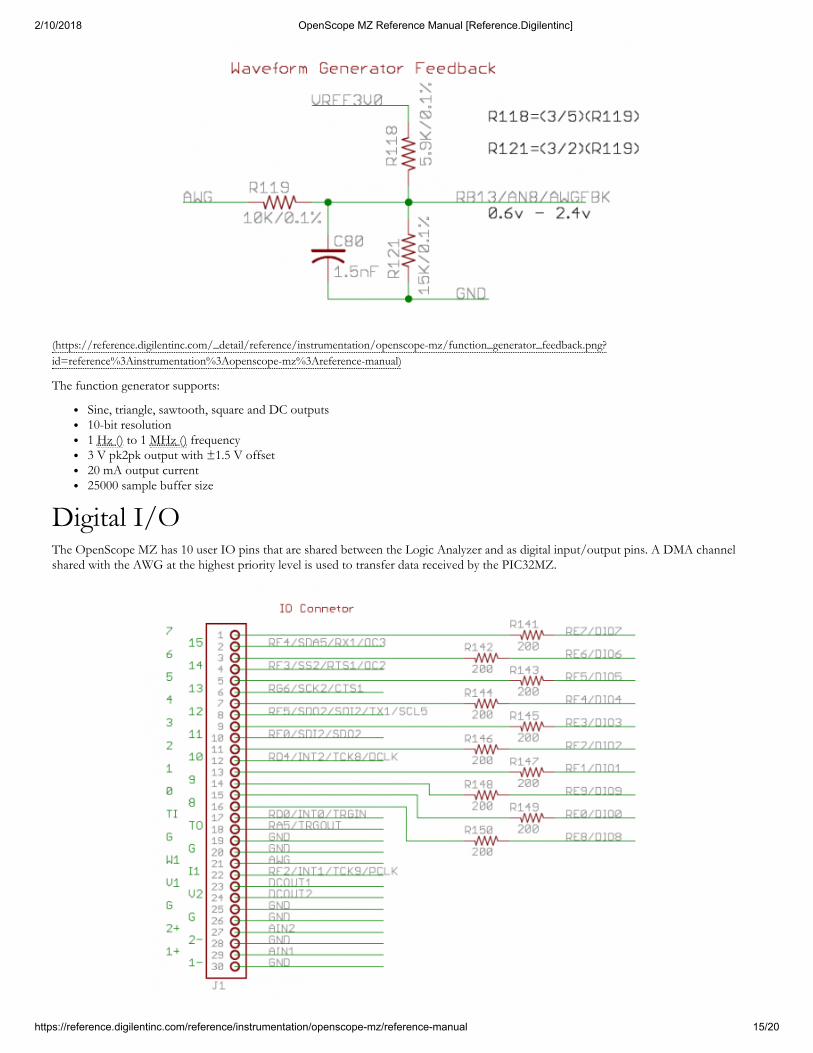
(https://reference.digilentinc.com/_detail/reference/instrumentation/openscope-mz/function_generator_feedback.png?id=reference%3Ainstrumentation%3Aopenscope-mz%3Areference-manual)
The function generator supports:
Sine, triangle, sawtooth, square and DC outputs10-bit resolution1 Hz () to 1 MHz () frequency3 V pk2pk output with ±1.5 V offset20 mA output current25000 sample buffer size
The OpenScope MZ has 10 user IO pins that are shared between the Logic Analyzer and as digital input/output pins. A DMA channelshared with the AWG at the highest priority level is used to transfer data received by the PIC32MZ.
Digital I/O

2/10/2018 OpenScope MZ Reference Manual [Reference.Digilentinc]
https://reference.digilentinc.com/reference/instrumentation/openscope-mz/reference-manual 16/20
(https://reference.digilentinc.com/_detail/reference/instrumentation/openscope-mz/io_pins.png?id=reference%3Ainstrumentation%3Aopenscope-mz%3Areference-manual)
10 Channels multiplexed between the Logic Analyzer and as general purpose IO3.3V CMOS logic7 mA source and 12 mA sink when used as GPIO ()Logic Analyzer has a sample rate of 10 MS/s ()Maximum buffer size of 32640 samples per channel for the logic analyzer
OpenScope MZ has two DC outputs that are driven by their own PWM output with a single PWM line for the DC offset. A gain circuit isimplmented on the OpenScope MZ to provide a voltage range of -4 V to 4 V for each channel. A feedback circuit is also present to allowfor calibration of the DC output.
(https://reference.digilentinc.com/_detail/reference/instrumentation/openscope-mz/dc_output_main.png?id=reference%3Ainstrumentation%3Aopenscope-mz%3Areference-manual)
(https://reference.digilentinc.com/_detail/reference/instrumentation/openscope-mz/dc_output_feedback.png?id=reference%3Ainstrumentation%3Aopenscope-mz%3Areference-manual)
2 channels±4 V50 mA per channel
A block diagram of how the OpenScope MZ communicates with the host is provided below:
DC Power Supplies
Communication with the host

2/10/2018 OpenScope MZ Reference Manual [Reference.Digilentinc]
https://reference.digilentinc.com/reference/instrumentation/openscope-mz/reference-manual 17/20
(https://reference.digilentinc.com/_detail/reference/instrumentation/openscope-mz/user_interface_communications.png?id=reference%3Ainstrumentation%3Aopenscope-mz%3Areference-manual)
OpenScope MZ uses an FTdI FT232RQ USB/Serial converter to handle the flow control between a host computer and a connectedOpenScope MZ. The host computer will need a USB 2.0 High Speed (or better) port to allow the OpenScope MZ to run at 1.25 MBaud(139 kB/s) and to negotiate 500 mA on the USB bus. Users may interact with the OpenScope MZ via a terminal in either Menu Mode orJSON Mode. A pair of DMA channels at the lowest priority are dedicated to the UART. If any other DMA channels stall out the UARTDMA, all communication with the host will cease.
The OpenScope MZ uses a MRF24WG0MA WiFi chip to enable wireless communication with a browser based UI, WaveFormsLive(https://reference.digilentinc.com/reference/software/waveforms-live/start) (WFL). The OpenScope MZ itself implements a simple HTTP Serverthat stores static web content on a μSD card and supports dynamic content implemented in the code through the Digilent deIP™ NetworkStack. More information about WFL and the Digilent Agent (https://reference.digilentinc.com/reference/software/digilent-agent/start) can befound on the OpenScope MZ Resource Center (https://reference.digilentinc.com/reference/instrumentation/openscope-mz/start).
8 out of 9 timers available on the PIC32MZ are utilized for the OpenScope MZ to trigger the ADCs, DMA transfers, PWM outputs, andtrigger delays. Two timers are dedicated to the ADC () channels, two are dedicated to the DC outputs, one for the DC offset, one for thefunction generator and logic analyzer, one for an external trigger, and one for the hardware protocol.
The PIC32MZ triggers are used to initiate and control all of the DMA transfers in the OpenScope MZ. When a trigger is enabled, a dataacquisition will run continuously before the trigger event because it is not known when the trigger event will occur. Data acquisition will alsocontinue to run until all post trigger data is collected. Due to data acquisition size limitations, it is not possible to measure a point of interestthat exists too far in advance prior to the trigger event. The reverse for a point of interest too far after a trigger event is also true.
Supported triggers for the oscilloscope are:
Rising or Falling Edge triggersRise/Fall time with lower and upper thresholdBy default WaveForms Live sets the lower threshold 30 mV below the upper threshold
Supported triggers for the logic analyzer are:
Rising, Falling or either Edge triggers
UART Interface
WiFi
Timers
Triggers

2/10/2018 OpenScope MZ Reference Manual [Reference.Digilentinc]
https://reference.digilentinc.com/reference/instrumentation/openscope-mz/reference-manual 18/20
Any of the 10 LA signal channels in any combinationPattern matching of the LA signal channels is not supported
8 out of 8 DMA channels available on the PIC32MZ are used on the OpenScope MZ. Two channels are dedicated to UART, a pair ofDMA channels are assigned to each interleaved ADC () channel for a total of four channels, one channel is shared between the functiongenerator and the logic analyzer and one dedicated to hardware protocol communication. All DMA channels can be triggered on anyinterrupt event and do not require the use of an ISR.
DMA is used to transfer data without utilizing the CPU by working in parallel with the CPU and has to ability to access peripherals and non-cached memory at much greater speeds. DMA cell transfers are serialized so care is taken in the OpenScope firmware to ensure thatmultiple channels are not triggered above 10 MT/s to prevent a high priority channel from stalling all other DMA channels.
9 PWM channels of the PIC32MZ are implemented on the OpenScope MZ. Two are used in the interleaving of the ADC () channels, threeare used for offsets for the AWG and both analog input channels, two are used for the DC outputs, and the remaining two used as offsetsfor the DC outputs.
The PWM outputs have 330 unique values ranging from 0 V to 3.3 V, with a step size of 10 mV. The internal clock runs at 100 MHz (),providing a PWM frequency of 303 kHz (). All of the analog designs on the OpenScope MZ are based on PWM values from 50 to 300 toallow some headroom for calibration.
The LEDs on the OpenScope MZ are used to indicate the current status of the OpenScope MZ hardware as follows:
Note: Firmware versions prior to 1.2.0 will not exhibit the LED () behavior described below.
Blue Off - Device is booting and not ready to use.Blue Flashing - Device is booted and ready to use but Wifi is not connected.Blue Solid - Device is booted and ready to use and Wifi is connected.
The three other LEDs blink the last octet of the OpenScope MZ's IP Address.Red Solid - Calibration or acquisition in progress.All user LEDs Solid - An error has occurred. Reboot the OpenScope MZ.When connected to a Wifi network the 3 user LEDs display the last octet of the OpenScope MZ's IP address by blinking the numberof times corresponding to that digit of the last octet in decimal. For example an OpenScope MZ with an IP address ending in '123'would blink LD1 once, LD2 twice and LD3 three times.
DMA
PWM
TroubleshootingLED Indicators

2/10/2018 OpenScope MZ Reference Manual [Reference.Digilentinc]
https://reference.digilentinc.com/reference/instrumentation/openscope-mz/reference-manual 19/20
First Name
Last Name
Email Address
Submit
Subscribe to our Newsletter
Xilinx UniversityProgram(https://store.digilentinc.com/partners/xilinx-university-program/)Technology Partners(https://store.digilentinc.com/technology-partners/)Distributors(https://store.digilentinc.com/our-distributors/)
Our Partners
Technical SupportForum(https://forum.digilentinc.com)Reference Wiki(https://reference.digilentinc.com)Contact Us(https://store.digilentinc.com/contact-us/)
Help
Videos(https://youtube.com/user/digilentinc)FAQ(https://resource.digilentinc.com/verify/faq)Store Info(https://store.digilentinc.com/store-info/)
Customer Info
About Us(https://store.digilentinc.com/ppageid=26)Shipping & Returns(https://store.digilentinc.com/returns/)Legal(https://store.digilentinc.com/lJobs(https://store.digilentinc.com/jInternships(https://store.digilentinc.com/i
Company Info
Connect With Us

2/10/2018 OpenScope MZ Reference Manual [Reference.Digilentinc]
https://reference.digilentinc.com/reference/instrumentation/openscope-mz/reference-manual 20/20
(https://twitter.com/digilentinc)
(https://www.facebook.com/Digilent)
(https://www.youtube.com/user/DigilentInc)
(https://instagram.com/digilentinc)
(https://github.com/digilent)
(https://www.reddit.com/r/digilent)
(https://www.linkedin.com/company/1454013)
(https://www.flickr.com/photos/127815101@N07)