Opening ceremony shaft for the Athens 2004...
11
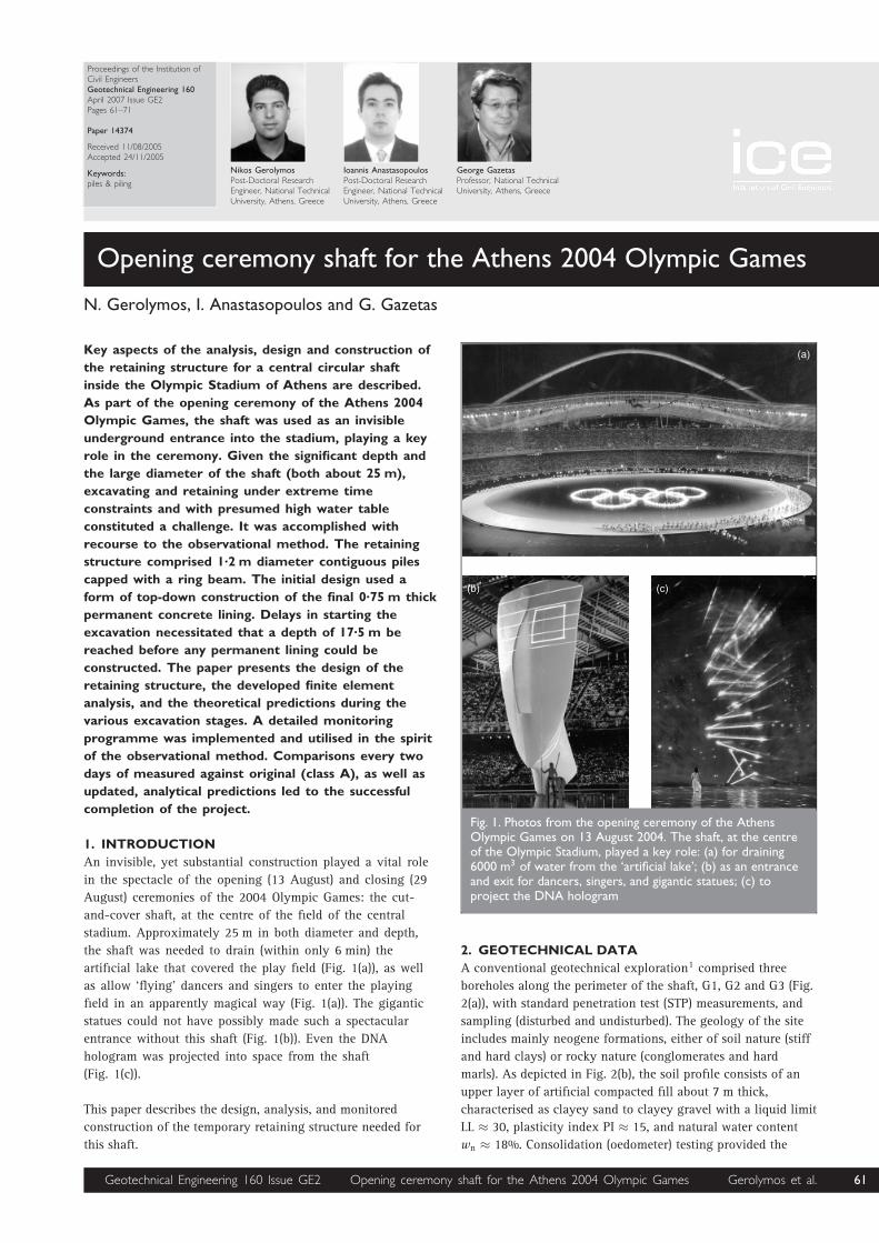
Proceedings of the Institution of Civil Engineers Geotechnical Engineering 160 April 2007 Issue GE2 Pages 61–71 Paper 14374 Received 11/08/2005 Accepted 24/11/2005 Keywords: piles & piling Nikos Gerolymos Post-Doctoral Research Engineer, National Technical University, Athens, Greece Ioannis Anastasopoulos Post-Doctoral Research Engineer, National Technical University, Athens, Greece George Gazetas Professor, National Technical University, Athens, Greece Opening ceremony shaft for the Athens 2004 Olympic Games N. Gerolymos, I. Anastasopoulos and G. Gazetas Key aspects of the analysis, design and construction of the retaining structure for a central circular shaft inside the Olympic Stadium of Athens are described. As part of the opening ceremony of the Athens 2004 Olympic Games, the shaft was used as an invisible underground entrance into the stadium, playing a key role in the ceremony. Given the significant depth and the large diameter of the shaft (both about 25 m), excavating and retaining under extreme time constraints and with presumed high water table constituted a challenge. It was accomplished with recourse to the observational method. The retaining structure comprised 1 . 2 m diameter contiguous piles capped with a ring beam. The initial design used a form of top-down construction of the final 0 . 75 m thick permanent concrete lining. Delays in starting the excavation necessitated that a depth of 17 . 5 m be reached before any permanent lining could be constructed. The paper presents the design of the retaining structure, the developed finite element analysis, and the theoretical predictions during the various excavation stages. A detailed monitoring programme was implemented and utilised in the spirit of the observational method. Comparisons every two days of measured against original (class A), as well as updated, analytical predictions led to the successful completion of the project. 1. INTRODUCTION An invisible, yet substantial construction played a vital role in the spectacle of the opening (13 August) and closing (29 August) ceremonies of the 2004 Olympic Games: the cut- and-cover shaft, at the centre of the field of the central stadium. Approximately 25 m in both diameter and depth, the shaft was needed to drain (within only 6 min) the artificial lake that covered the play field (Fig. 1(a)), as well as allow ‘flying’ dancers and singers to enter the playing field in an apparently magical way (Fig. 1(a)). The gigantic statues could not have possibly made such a spectacular entrance without this shaft (Fig. 1(b)). Even the DNA hologram was projected into space from the shaft (Fig. 1(c)). This paper describes the design, analysis, and monitored construction of the temporary retaining structure needed for this shaft. 2. GEOTECHNICAL DATA A conventional geotechnical exploration 1 comprised three boreholes along the perimeter of the shaft, G1, G2 and G3 (Fig. 2(a)), with standard penetration test (STP) measurements, and sampling (disturbed and undisturbed). The geology of the site includes mainly neogene formations, either of soil nature (stiff and hard clays) or rocky nature (conglomerates and hard marls). As depicted in Fig. 2(b), the soil profile consists of an upper layer of artificial compacted fill about 7 m thick, characterised as clayey sand to clayey gravel with a liquid limit LL 30, plasticity index PI 15, and natural water content w n 18%. Consolidation (oedometer) testing provided the Fig. 1. Photos from the opening ceremony of the Athens Olympic Games on 13 August 2004. The shaft, at the centre of the Olympic Stadium, played a key role: (a) for draining 6000 m 3 of water from the ‘artificial lake’; (b) as an entrance and exit for dancers, singers, and gigantic statues; (c) to project the DNA hologram Geotechnical Engineering 160 Issue GE2 Opening ceremony shaft for the Athens 2004 Olympic Games Gerolymos et al. 61
Transcript of Opening ceremony shaft for the Athens 2004...
Proceedings of the Institution ofCivil EngineersGeotechnical Engineering 160April 2007 Issue GE2Pages 61–71
Paper 14374
Received 11/08/2005Accepted 24/11/2005
Keywords:piles & piling
Nikos GerolymosPost-Doctoral ResearchEngineer, National TechnicalUniversity, Athens, Greece
Ioannis AnastasopoulosPost-Doctoral ResearchEngineer, National TechnicalUniversity, Athens, Greece
George GazetasProfessor, National TechnicalUniversity, Athens, Greece
Opening ceremony shaft for the Athens 2004 Olympic Games
N. Gerolymos, I. Anastasopoulos and G. Gazetas
Key aspects of the analysis, design and construction of
the retaining structure for a central circular shaft
inside the Olympic Stadium of Athens are described.
As part of the opening ceremony of the Athens 2004
Olympic Games, the shaft was used as an invisible
underground entrance into the stadium, playing a key
role in the ceremony. Given the significant depth and
the large diameter of the shaft (both about 25 m),
excavating and retaining under extreme time
constraints and with presumed high water table
constituted a challenge. It was accomplished with
recourse to the observational method. The retaining
structure comprised 1.2 m diameter contiguous piles
capped with a ring beam. The initial design used a
form of top-down construction of the final 0.75 m thick
permanent concrete lining. Delays in starting the
excavation necessitated that a depth of 17.5 m be
reached before any permanent lining could be
constructed. The paper presents the design of the
retaining structure, the developed finite element
analysis, and the theoretical predictions during the
various excavation stages. A detailed monitoring
programme was implemented and utilised in the spirit
of the observational method. Comparisons every two
days of measured against original (class A), as well as
updated, analytical predictions led to the successful
completion of the project.
1. INTRODUCTION
An invisible, yet substantial construction played a vital role
in the spectacle of the opening (13 August) and closing (29
August) ceremonies of the 2004 Olympic Games: the cut-
and-cover shaft, at the centre of the field of the central
stadium. Approximately 25 m in both diameter and depth,
the shaft was needed to drain (within only 6 min) the
artificial lake that covered the play field (Fig. 1(a)), as well
as allow ‘flying’ dancers and singers to enter the playing
field in an apparently magical way (Fig. 1(a)). The gigantic
statues could not have possibly made such a spectacular
entrance without this shaft (Fig. 1(b)). Even the DNA
hologram was projected into space from the shaft
(Fig. 1(c)).
This paper describes the design, analysis, and monitored
construction of the temporary retaining structure needed for
this shaft.
2. GEOTECHNICAL DATA
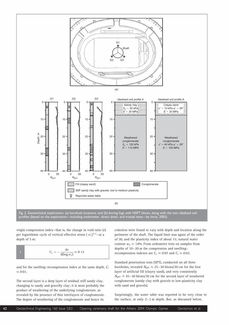
A conventional geotechnical exploration1 comprised three
boreholes along the perimeter of the shaft, G1, G2 and G3 (Fig.
2(a)), with standard penetration test (STP) measurements, and
sampling (disturbed and undisturbed). The geology of the site
includes mainly neogene formations, either of soil nature (stiff
and hard clays) or rocky nature (conglomerates and hard
marls). As depicted in Fig. 2(b), the soil profile consists of an
upper layer of artificial compacted fill about 7 m thick,
characterised as clayey sand to clayey gravel with a liquid limit
LL � 30, plasticity index PI � 15, and natural water content
wn � 18%. Consolidation (oedometer) testing provided the
����
���� ����
Fig. 1. Photos from the opening ceremony of the AthensOlympic Games on 13 August 2004. The shaft, at the centreof the Olympic Stadium, played a key role: (a) for draining6000 m3 of water from the ‘artificial lake’; (b) as an entranceand exit for dancers, singers, and gigantic statues; (c) toproject the DNA hologram
Geotechnical Engineering 160 Issue GE2 Opening ceremony shaft for the Athens 2004 Olympic Games Gerolymos et al. 61
virgin compression index—that is, the change in void ratio (e)
per logarithmic cycle of vertical effective stress ( � 9v)2,3—at adepth of 5 m:
Cc ¼ � de
d(log � 9v)� 0:131
and for the swelling–recompression index at the same depth, Cr� 0.01.
The second layer is a deep layer of residual stiff sandy clay,
changing to sandy and gravelly clay; it is most probably the
product of weathering of the underlying conglomerate, as
revealed by the presence of thin interlayers of conglomerate.
The degree of weathering of the conglomerate and hence its
cohesion were found to vary with depth and location along the
perimeter of the shaft. The liquid limit was again of the order
of 30, and the plasticity index of about 15; natural water
content wn � 14%. From oedometer tests on samples from
depths of 10–20 m the compression and swelling–
recompression indexes are Cc � 0.07 and Cr � 0.02.
Standard penetration tests (SPT), conducted on all three
boreholes, revealed NSPT � 25–30 blows/30 cm for the first
layer of artificial fill (clayey sand), and very consistently
NSPT > 45–50 blows/30 cm for the second layer of weathered
conglomerate (sandy clay with gravels to low-plasticity clay
with sand and gravels).
Surprisingly, the water table was reported to be very close to
the surface, at only 2–3 m depth. But, as discussed below,
� �� � �� � ���� �� ��
�� ���� ������������� ��
�����������������������������
� ��� � ���� ��! ��� �����"#��������""����
�� ���� ������������� ��
� ��� � ���� ��! ���
�����$����������#%&����"�����
'��������� �������
����� ������������(���� ��) ��*���(����! ���!�����������
+ ���� ��(�� ������
,�� ��! ���
,��� �����������"����������#-&
���������
."
.# .�
�����
."�
"�
#�
��
$�
/ ���0�!
.#�
"�
#�
��
$�
.��
"�
#�
��
$�
�
"�
#�
��
$�
�
"�
#�
��
$�
���
���
Fig. 2. Geotechnical exploration: (a) borehole locations, and (b) boring logs with NSPT blows, along with the two idealised soilprofiles (based on the exploration—including oedometer, direct shear, and triaxial tests—by Istria, 2003)
62 Geotechnical Engineering 160 Issue GE2 Opening ceremony shaft for the Athens 2004 Olympic Games Gerolymos et al.
the long-term interpretation
of this measurement was
questioned.
Strength characteristics were
obtained from a limited
number of conventional
laboratory test results of
direct shear and triaxial
compression (both CU and
UU type). Average properties
are used from the two
alternative idealised profiles
shown in Fig. 2: for the
artificial fill, cohesion c9 ¼10 kPa, friction angle �9 ¼298, and Young’s modulus of
elasticity E ¼ 30 MPa; for the
sandy clay, c9 ¼ 40 kPa, �9 ¼268, and E ¼ 100 MPa (soil
profile B).
Alternatively (soil profile A),
we assumed undrained soil
behaviour, with undrained
shear strength Su ¼ 50 kPa
and 120 kPa, for the first and
second layer respectively.
Young’s modulus of elasticity
was assigned values of E ¼35 MPa for the top layer and
E ¼ 115 MPa for the second layer. The selection of a constant
Young’s modulus with depth, E ¼ 115 MPa, for the second
layer is obviously a conservative approximation, as it is based
on a few indirect measurements at depth up to 15 m. A logical
alternative would be to take E as increasing linearly with
depth.4 A coefficient of lateral stress ‘at rest’, K0, of 0.50 was
assumed as the basic value in our analyses.
Finally, based on the results of in situ Maag tests,1 the
permeability k was evaluated to be of the order of 2 3 10�7
m/s and 5 3 10�8 m/s for the first (artificial fill) and second
(weathered conglomerate) layers respectively.
Admittedly, soil testing (in situ and in the laboratory) was not
‘state of the art’. All the above values of soil properties reflect
simply our best judgement: hence a broad parametric
investigation was unavoidably part of our analytical
exploration into possible scenarios of response.
3. EXCAVATION AND RETAINING ALTERNATIVES
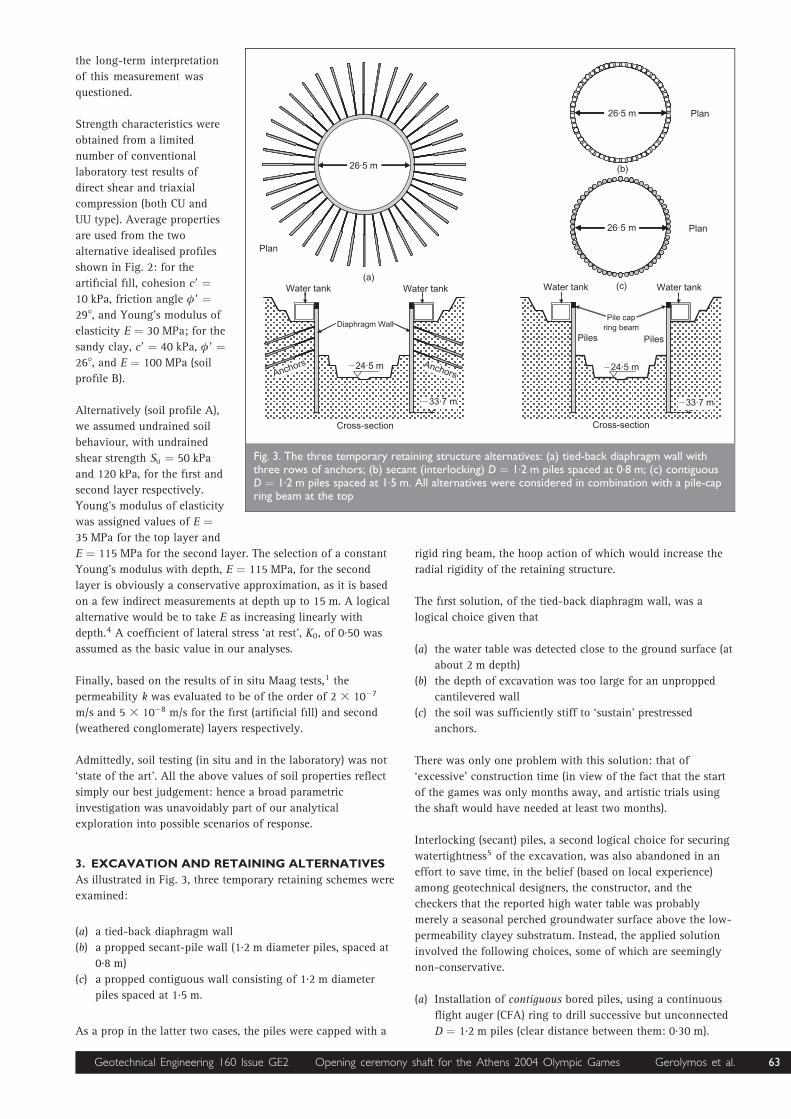
As illustrated in Fig. 3, three temporary retaining schemes were
examined:
(a) a tied-back diaphragm wall
(b) a propped secant-pile wall (1.2 m diameter piles, spaced at
0.8 m)
(c) a propped contiguous wall consisting of 1.2 m diameter
piles spaced at 1.5 m.
As a prop in the latter two cases, the piles were capped with a
rigid ring beam, the hoop action of which would increase the
radial rigidity of the retaining structure.
The first solution, of the tied-back diaphragm wall, was a
logical choice given that
(a) the water table was detected close to the ground surface (at
about 2 m depth)
(b) the depth of excavation was too large for an unpropped
cantilevered wall
(c) the soil was sufficiently stiff to ‘sustain’ prestressed
anchors.
There was only one problem with this solution: that of
‘excessive’ construction time (in view of the fact that the start
of the games was only months away, and artistic trials using
the shaft would have needed at least two months).
Interlocking (secant) piles, a second logical choice for securing
watertightness5 of the excavation, was also abandoned in an
effort to save time, in the belief (based on local experience)
among geotechnical designers, the constructor, and the
checkers that the reported high water table was probably
merely a seasonal perched groundwater surface above the low-
permeability clayey substratum. Instead, the applied solution
involved the following choices, some of which are seemingly
non-conservative.
(a) Installation of contiguous bored piles, using a continuous
flight auger (CFA) ring to drill successive but unconnected
D ¼ 1.2 m piles (clear distance between them: 0.30 m).
�� �
�#$1��!
���12�!
��� ������ ��� ������
�#$1��!
���12�!
���
���
,����3� ����� ,����3� �����
���
���
#%1��!
#%1��!
#%1��!
�� �
/������ !�����
��� ������ ��� ������
���
���
������� �������
�� ������� �� �!
Fig. 3. The three temporary retaining structure alternatives: (a) tied-back diaphragm wall withthree rows of anchors; (b) secant (interlocking) D ¼ 1.2 m piles spaced at 0.8 m; (c) contiguousD ¼ 1.2 m piles spaced at 1.5 m. All alternatives were considered in combination with a pile-capring beam at the top
Geotechnical Engineering 160 Issue GE2 Opening ceremony shaft for the Athens 2004 Olympic Games Gerolymos et al. 63
Maximum verticality tolerance of 1.5% in depth was
specified for pile installation. Their length: 9 m longer than
the depth of excavation.
(b) As prestressed anchors and struts were beyond
consideration, judged as time consuming choices, lateral
support of the piled wall was provided (indirectly but
efficiently) by a ring beam at the top of the piles. Its cross-
section was 1.20 m 3 1.20 m, and it played the role of a
substantial stiff prop. Moreover, to further save precious
time, a modified top-down construction sequence was to be
carried out. When excavation reached 9.5 m depth, the top
internal ring of the (final) permanent lining would be
constructed (from the top of the ring beam down to a depth
of 8.5 m). Then excavation would proceed, and
construction of the second internal permanent lining ring
would follow, and so on until completion.
(c) As leakage through soil between the (contiguous) piles
could not be prevented, to minimise the potential
groundwater hazard horizontal drainage pipes 10 cm in
diameter would be installed between the piles as densely as
the need arose with the progress of excavation. This would
relieve the water pressures to some extent and allow for
quick drainage (with sump pumps) from the bottom of the
excavation.
(d) Finally, in view of the several non-conservative choices
made, and the inherent uncertainties of the problem, the
observational method, as advocated by Peck in 1969 in the
Ninth Rankine Lecture,6 was implemented. (For recent
reviews of the method see refs 7 and 8.) A centrepiece of
the method was the installation of a reasonably
comprehensive monitoring system, described below. Key
response variables were measured as construction
proceeded, and were compared with the numerically
computed values. Modifications to the design and
construction were planned in advance, in case the most
unfavourable of the foreseeable deviations of the
measurements from the numerical predictions were to
occur.
4. STAGES OF SHAFT CONSTRUCTION
The original schedule of top-down construction had to be
slightly modified owing to some unforeseen delays. To save
time, excavation would now proceed to 17.5 m depth before
any internal lining was installed. Referring to Fig. 4, the most
important stages in the construction of the shaft were as
follows.
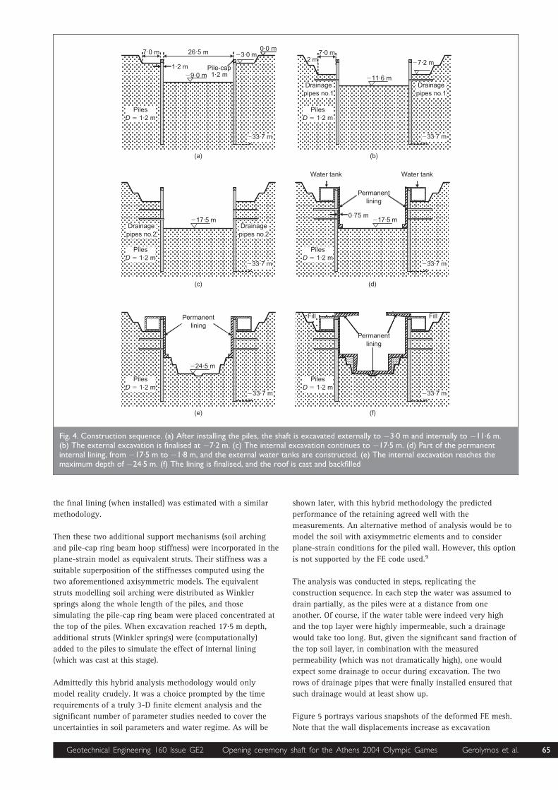
(a) Excavation to 1.5 m depth, followed by installation of the
piles to 33.7 m depth, and casting of the pile-cap ring
beam.
(b) External excavation to 3 m depth and internal to 9 m
depth. External excavation was required for placing the
water tanks (outside the shaft). Once the depth of 9 m was
reached it was originally planned to construct the 9 m high
internal (permanent) lining ring, in a kind of top-down
construction. Measurements and analysis suggested that
time could be saved without jeopardizing safety, if this
casting of internal lining were postponed for greater depth.
(c) External excavation finalised at 7.2 m depth; internal at
11.5 m depth.
(d) Installation of a first row of drainage pipes at 9 m depth;
internal excavation to 17.5 m depth.
(e) Construction of the reinforced concrete permanent internal
lining from bottom 17.5 m depth to top. (Construction in
two stages as originally planned, from 9 m depth to top,
and from 17.5 m to 9 m depth, would have caused a few
weeks’ delay.)
( f ) Excavation to the final depth of 24.5 m.
(g) Construction of the lower part of the internal permanent
lining along with the bottom slab.
(h) Construction of the retractable roof.
The only constraint in the design of the excavation and the
retaining system was to prevent yielding of the piles. This was
equivalent to a maximum pile deflection not greater than
about 3 cm.
5. ANALYSIS OF STAGED CONSTRUCTION
Despite the axial symmetry of the excavation, strictly speaking
the problem was not axisymmetric in mechanics terms, in view
of the fact that the piles were not in contact and hence they
could not transmit hoop forces (i.e. tangential forces along the
periphery). On the other hand, if (hypothetically) the radius of
the shaft were very large (compared with depth) the problem
could be reduced to a plane-strain piled-wall problem.
Obviously, reality lies somewhere between the plane-strain and
the axisymmetric idealisations. Also, the pile-cap ring beam at
the top is essentially under axisymmetric conditions, carrying
primarily hoop forces (i.e. axial compressive load).
So, from the analytical point of view, although things would
have been really straightforward with a diaphragm wall, and
even with a secant pile alternative (in first approximation), as
axisymmetric conditions would be reality, the chosen
supporting system necessitated a different methodology.
The analysis utilised the finite-element code PLAXIS.9 To
account for the aforementioned ‘semi’-axisymmetric nature of
the problem, we applied a hybrid methodology. The basic
analysis was conducted in plane strain, but after making two
simple intuitive corrections: (a) for arching (through several
axisymmetric finite element analyses as described below); and
(b) for the contribution of the hoop stiffness of the pile-cap
ring beam. In the basic analysis the soil was modelled through
three-noded plane-strain elements, and the piles as beams
connected to the soil through a Coulomb sliding interface. The
Mohr–Coulomb constitutive law was assumed for the soil, 4
and the piles were considered as elastic.
The aforementioned additional support afforded by the
axisymmetry of the excavation was estimated by conducting
(a) an axisymmetric analysis of the soil without the piles
(b) an axisymmetric analysis of the pile-cap ring beam
(c) an axisymmetric analysis of the internal permanent ring
lining.
For (a), full excavation to the maximum depth (24.5 m) was
considered. Then a uniform horizontal radial load of 1 kPa was
applied on the vertical excavation face. With the computed
horizontal displacement of the excavation face, we derived an
equivalent stiffness of the support, which included the
contribution of soil arching (due to axisymmetry). The effect of
the additional support provided by the pile-cap ring beam and
64 Geotechnical Engineering 160 Issue GE2 Opening ceremony shaft for the Athens 2004 Olympic Games Gerolymos et al.
the final lining (when installed) was estimated with a similar
methodology.
Then these two additional support mechanisms (soil arching
and pile-cap ring beam hoop stiffness) were incorporated in the
plane-strain model as equivalent struts. Their stiffness was a
suitable superposition of the stiffnesses computed using the
two aforementioned axisymmetric models. The equivalent
struts modelling soil arching were distributed as Winkler
springs along the whole length of the piles, and those
simulating the pile-cap ring beam were placed concentrated at
the top of the piles. When excavation reached 17.5 m depth,
additional struts (Winkler springs) were (computationally)
added to the piles to simulate the effect of internal lining
(which was cast at this stage).
Admittedly this hybrid analysis methodology would only
model reality crudely. It was a choice prompted by the time
requirements of a truly 3-D finite element analysis and the
significant number of parameter studies needed to cover the
uncertainties in soil parameters and water regime. As will be
shown later, with this hybrid methodology the predicted
performance of the retaining agreed well with the
measurements. An alternative method of analysis would be to
model the soil with axisymmetric elements and to consider
plane-strain conditions for the piled wall. However, this option
is not supported by the FE code used.9
The analysis was conducted in steps, replicating the
construction sequence. In each step the water was assumed to
drain partially, as the piles were at a distance from one
another. Of course, if the water table were indeed very high
and the top layer were highly impermeable, such a drainage
would take too long. But, given the significant sand fraction of
the top soil layer, in combination with the measured
permeability (which was not dramatically high), one would
expect some drainage to occur during excavation. The two
rows of drainage pipes that were finally installed ensured that
such drainage would at least show up.
Figure 5 portrays various snapshots of the deformed FE mesh.
Note that the wall displacements increase as excavation
�-1��!
��1��!
���12�!
#%1��!
"1#�!
21��!
�� 3���"1#�!
�"21��!
���12�!
���12�!
���
���
���
�1��!
���
�#$1��!
���12�!
� �
�""1%�!
�21#�!
���12�!
21��!#�!
���
�"21��!
���12�!
�12��!
�� �����"1#�!
�� �����"1#�!
�� �����"1#�!
�� �����"1#�!
�� �����"1#�!
�� �����"1#�!
/����� ��� ����4"
/����� ��� ����4"
/����� ��� ����4#
/����� ��� ����4#
�!�� �������
�!�� �������
�!�� �������
��� ������ ��� ������
'��� '���
Fig. 4. Construction sequence. (a) After installing the piles, the shaft is excavated externally to �3.0 m and internally to �11.6 m.(b) The external excavation is finalised at �7.2 m. (c) The internal excavation continues to �17.5 m. (d) Part of the permanentinternal lining, from �17.5 m to �1.8 m, and the external water tanks are constructed. (e) The internal excavation reaches themaximum depth of �24.5 m. (f) The lining is finalised, and the roof is cast and backfilled
Geotechnical Engineering 160 Issue GE2 Opening ceremony shaft for the Athens 2004 Olympic Games Gerolymos et al. 65
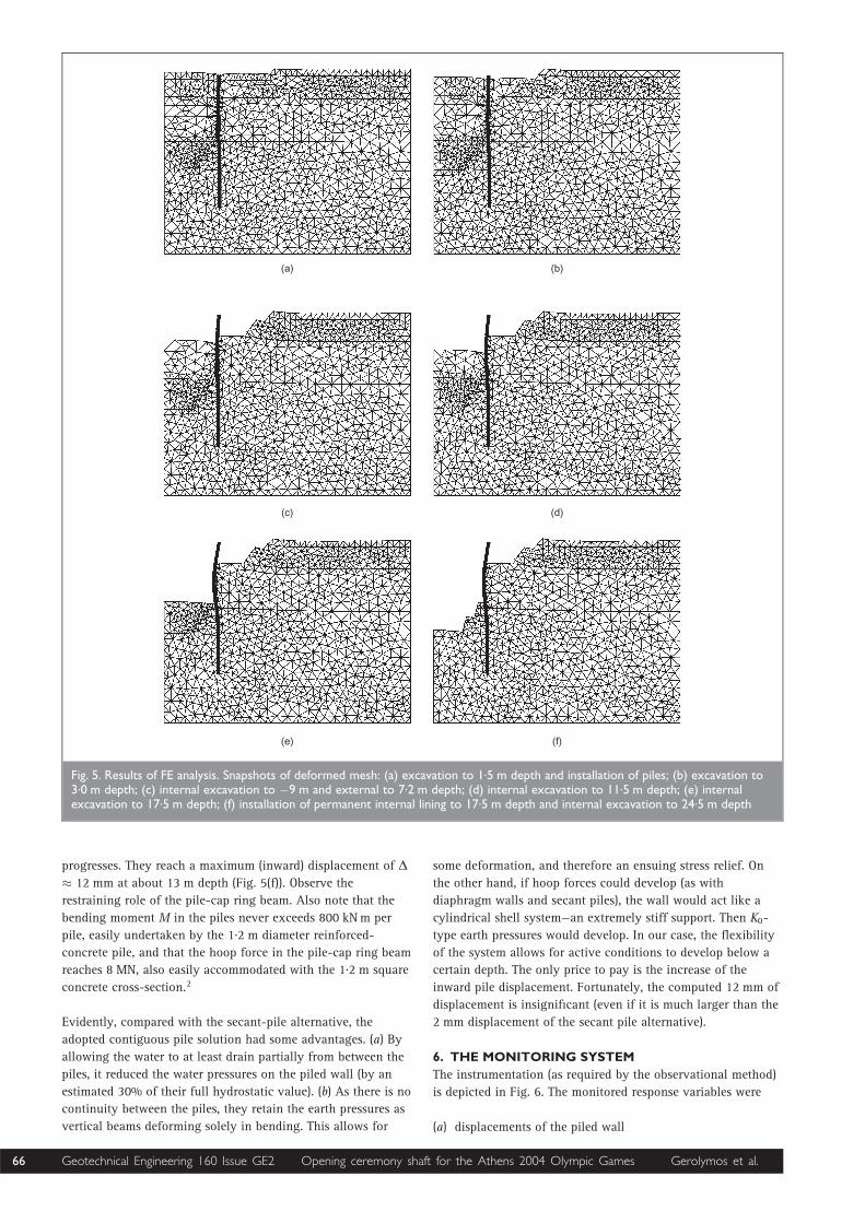
progresses. They reach a maximum (inward) displacement of ˜� 12 mm at about 13 m depth (Fig. 5(f)). Observe the
restraining role of the pile-cap ring beam. Also note that the
bending moment M in the piles never exceeds 800 kNm per
pile, easily undertaken by the 1.2 m diameter reinforced-
concrete pile, and that the hoop force in the pile-cap ring beam
reaches 8 MN, also easily accommodated with the 1.2 m square
concrete cross-section.2
Evidently, compared with the secant-pile alternative, the
adopted contiguous pile solution had some advantages. (a) By
allowing the water to at least drain partially from between the
piles, it reduced the water pressures on the piled wall (by an
estimated 30% of their full hydrostatic value). (b) As there is no
continuity between the piles, they retain the earth pressures as
vertical beams deforming solely in bending. This allows for
some deformation, and therefore an ensuing stress relief. On
the other hand, if hoop forces could develop (as with
diaphragm walls and secant piles), the wall would act like a
cylindrical shell system—an extremely stiff support. Then K0-
type earth pressures would develop. In our case, the flexibility
of the system allows for active conditions to develop below a
certain depth. The only price to pay is the increase of the
inward pile displacement. Fortunately, the computed 12 mm of
displacement is insignificant (even if it is much larger than the
2 mm displacement of the secant pile alternative).
6. THE MONITORING SYSTEM
The instrumentation (as required by the observational method)
is depicted in Fig. 6. The monitored response variables were
(a) displacements of the piled wall
��� ���
��� ���
� � ���
Fig. 5. Results of FE analysis. Snapshots of deformed mesh: (a) excavation to 1.5 m depth and installation of piles; (b) excavation to3.0 m depth; (c) internal excavation to �9 m and external to 7.2 m depth; (d) internal excavation to 11.5 m depth; (e) internalexcavation to 17.5 m depth; (f) installation of permanent internal lining to 17.5 m depth and internal excavation to 24.5 m depth
66 Geotechnical Engineering 160 Issue GE2 Opening ceremony shaft for the Athens 2004 Olympic Games Gerolymos et al.
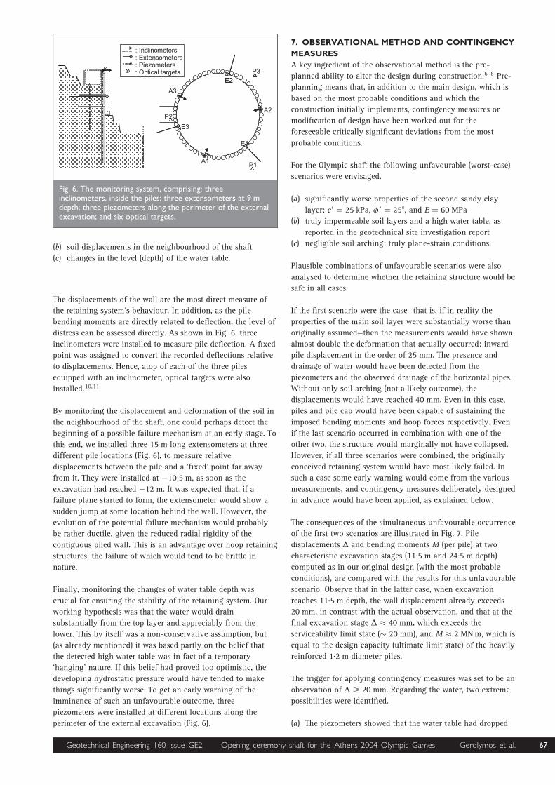
(b) soil displacements in the neighbourhood of the shaft
(c) changes in the level (depth) of the water table.
The displacements of the wall are the most direct measure of
the retaining system’s behaviour. In addition, as the pile
bending moments are directly related to deflection, the level of
distress can be assessed directly. As shown in Fig. 6, three
inclinometers were installed to measure pile deflection. A fixed
point was assigned to convert the recorded deflections relative
to displacements. Hence, atop of each of the three piles
equipped with an inclinometer, optical targets were also
installed.10,11
By monitoring the displacement and deformation of the soil in
the neighbourhood of the shaft, one could perhaps detect the
beginning of a possible failure mechanism at an early stage. To
this end, we installed three 15 m long extensometers at three
different pile locations (Fig. 6), to measure relative
displacements between the pile and a ‘fixed’ point far away
from it. They were installed at �10.5 m, as soon as the
excavation had reached �12 m. It was expected that, if a
failure plane started to form, the extensometer would show a
sudden jump at some location behind the wall. However, the
evolution of the potential failure mechanism would probably
be rather ductile, given the reduced radial rigidity of the
contiguous piled wall. This is an advantage over hoop retaining
structures, the failure of which would tend to be brittle in
nature.
Finally, monitoring the changes of water table depth was
crucial for ensuring the stability of the retaining system. Our
working hypothesis was that the water would drain
substantially from the top layer and appreciably from the
lower. This by itself was a non-conservative assumption, but
(as already mentioned) it was based partly on the belief that
the detected high water table was in fact of a temporary
‘hanging’ nature. If this belief had proved too optimistic, the
developing hydrostatic pressure would have tended to make
things significantly worse. To get an early warning of the
imminence of such an unfavourable outcome, three
piezometers were installed at different locations along the
perimeter of the external excavation (Fig. 6).
7. OBSERVATIONAL METHOD AND CONTINGENCY
MEASURES
A key ingredient of the observational method is the pre-
planned ability to alter the design during construction.6–8 Pre-
planning means that, in addition to the main design, which is
based on the most probable conditions and which the
construction initially implements, contingency measures or
modification of design have been worked out for the
foreseeable critically significant deviations from the most
probable conditions.
For the Olympic shaft the following unfavourable (worst-case)
scenarios were envisaged.
(a) significantly worse properties of the second sandy clay
layer: c9 ¼ 25 kPa, �9 ¼ 258, and E ¼ 60 MPa
(b) truly impermeable soil layers and a high water table, as
reported in the geotechnical site investigation report
(c) negligible soil arching: truly plane-strain conditions.
Plausible combinations of unfavourable scenarios were also
analysed to determine whether the retaining structure would be
safe in all cases.
If the first scenario were the case—that is, if in reality the
properties of the main soil layer were substantially worse than
originally assumed—then the measurements would have shown
almost double the deformation that actually occurred: inward
pile displacement in the order of 25 mm. The presence and
drainage of water would have been detected from the
piezometers and the observed drainage of the horizontal pipes.
Without only soil arching (not a likely outcome), the
displacements would have reached 40 mm. Even in this case,
piles and pile cap would have been capable of sustaining the
imposed bending moments and hoop forces respectively. Even
if the last scenario occurred in combination with one of the
other two, the structure would marginally not have collapsed.
However, if all three scenarios were combined, the originally
conceived retaining system would have most likely failed. In
such a case some early warning would come from the various
measurements, and contingency measures deliberately designed
in advance would have been applied, as explained below.
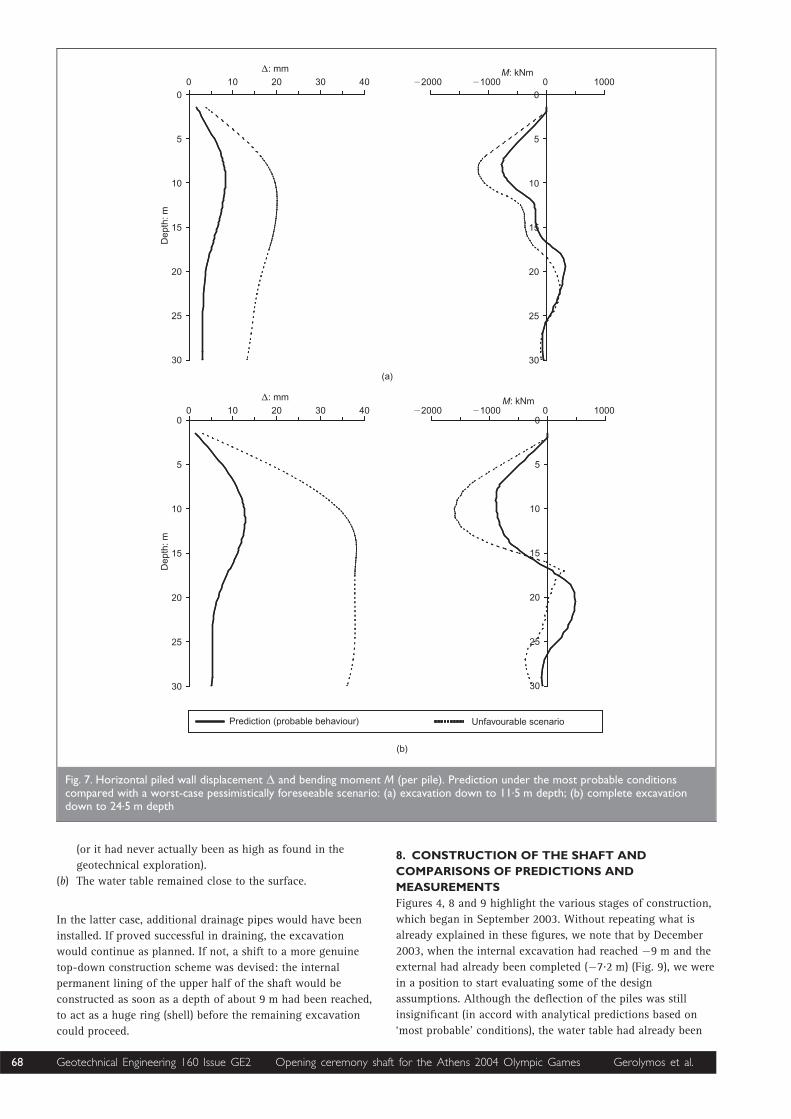
The consequences of the simultaneous unfavourable occurrence
of the first two scenarios are illustrated in Fig. 7. Pile
displacements ˜ and bending moments M (per pile) at two
characteristic excavation stages (11.5 m and 24.5 m depth)
computed as in our original design (with the most probable
conditions), are compared with the results for this unfavourable
scenario. Observe that in the latter case, when excavation
reaches 11.5 m depth, the wall displacement already exceeds
20 mm, in contrast with the actual observation, and that at the
final excavation stage ˜ � 40 mm, which exceeds the
serviceability limit state (� 20 mm), and M � 2 MNm, which is
equal to the design capacity (ultimate limit state) of the heavily
reinforced 1.2 m diameter piles.
The trigger for applying contingency measures was set to be an
observation of ˜ > 20 mm. Regarding the water, two extreme
possibilities were identified.
(a) The piezometers showed that the water table had dropped
��
�#
�"
5�
5#
5"
0��������! � ��0�56� ���! � ��0�� 7�! � ��0�8���������� �� �
#
"
5#
Fig. 6. The monitoring system, comprising: threeinclinometers, inside the piles; three extensometers at 9 mdepth; three piezometers along the perimeter of the externalexcavation; and six optical targets.
Geotechnical Engineering 160 Issue GE2 Opening ceremony shaft for the Athens 2004 Olympic Games Gerolymos et al. 67
(or it had never actually been as high as found in the
geotechnical exploration).
(b) The water table remained close to the surface.
In the latter case, additional drainage pipes would have been
installed. If proved successful in draining, the excavation
would continue as planned. If not, a shift to a more genuine
top-down construction scheme was devised: the internal
permanent lining of the upper half of the shaft would be
constructed as soon as a depth of about 9 m had been reached,
to act as a huge ring (shell) before the remaining excavation
could proceed.
8. CONSTRUCTION OF THE SHAFT AND
COMPARISONS OF PREDICTIONS AND
MEASUREMENTS
Figures 4, 8 and 9 highlight the various stages of construction,
which began in September 2003. Without repeating what is
already explained in these figures, we note that by December
2003, when the internal excavation had reached �9 m and the
external had already been completed (�7.2 m) (Fig. 9), we were
in a position to start evaluating some of the design
assumptions. Although the deflection of the piles was still
insignificant (in accord with analytical predictions based on
‘most probable’ conditions), the water table had already been
� ���������������� �� ��)����� 9���)������ ��� �����
���
���
�� ��
�0�!! �0��:!� "� #� �� $� �#��� �"��� � "���
�
�
"�
"�
#�
#�
/ �
��0�!
�
�
"�
"�
#�
#�
�� ��
�0�!! �0��:!� "� #� �� $� �#��� �"��� � "���
�
�
"�
"�
#�
#�
/ ���0�!
�
�
"�
"�
#�
#�
Fig. 7. Horizontal piled wall displacement ˜ and bending moment M (per pile). Prediction under the most probable conditionscompared with a worst-case pessimistically foreseeable scenario: (a) excavation down to 11.5 m depth; (b) complete excavationdown to 24.5 m depth
68 Geotechnical Engineering 160 Issue GE2 Opening ceremony shaft for the Athens 2004 Olympic Games Gerolymos et al.

��� ���
��� ���
Fig. 8. (a) At the end of September 2003 the soil surface was excavated to 1.5 m depth andinstallation of the piles begun. 1 December 2003: (b) external excavation finalised at 7.2 m depth(note ‘missing’ piece of the ring to make a temporary entrance and hence speed up the initialstage of excavation); (c) as hoped, the water table was not at 2 m depth but at 7 m depth onaverage, essentially coinciding with the bottom of the external excavation; (d) pile-cap ring still‘open’ at the location of the ramp
��� ���
���
���
Fig. 9. (a) 8 December 2003: the internal excavation had reached �11.6 m internally and the firstrow of drainage pipes had been installed at �9 m. (b) 12 December 2003: casting of the watertank along the external perimeter of the shaft has begun. (c) 20 December 2003: the ring beamis now in place. Closing of the gap in the pile cap made excavation to greater depth possiblewithout any further lateral support. (d) 2 January 2004: the excavation reaches �17.5 m insidethe shaft. Drainage from the pipes is minimal
Geotechnical Engineering 160 Issue GE2 Opening ceremony shaft for the Athens 2004 Olympic Games Gerolymos et al. 69
lowered substantially: on 1 December it was at about �7 m on
average (�6.5 m on the north side and �7.3 m on the south).
The piezometers were consistent with optical observations. One
thing that was appreciably different from the design was the
pile-cap ring beam. As seen in Fig. 8, the contractor was given
permission to leave a 4 m wide opening on the pile-cap ring
beam, as this would enable him to excavate at a faster rate.
However, an open beam does not transmit hoop forces:
therefore it does not act as a ring and cannot play the role of a
prop. Acceptance of this unsafe modification during the early
stages of excavation could be allowed only by a slight change
in the schedule of excavations so that the difference between
external and internal excavation remained merely 2 m.
Up to that point, construction had proceeded as anticipated.
After the first row of drainage pipes had been installed, it
became evident that the stiff sandy clay was either not very
wet, or was not draining fast. One of the contributing factors to
such behaviour was the fact that the water table was not as
high as originally found, but was actually just above the
interface between the upper artificial fill and the stiff clay.
Nevertheless, to be on the safe side, drainage pipes continued
to be installed.
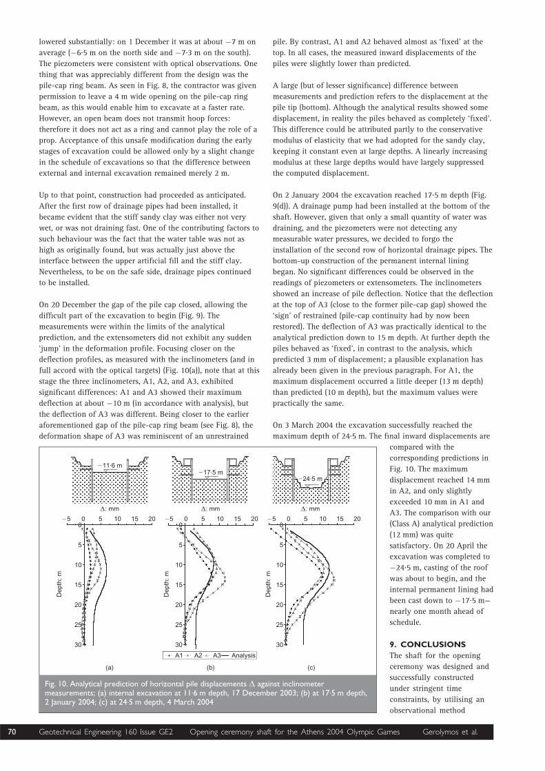
On 20 December the gap of the pile cap closed, allowing the
difficult part of the excavation to begin (Fig. 9). The
measurements were within the limits of the analytical
prediction, and the extensometers did not exhibit any sudden
‘jump’ in the deformation profile. Focusing closer on the
deflection profiles, as measured with the inclinometers (and in
full accord with the optical targets) (Fig. 10(a)), note that at this
stage the three inclinometers, A1, A2, and A3, exhibited
significant differences: A1 and A3 showed their maximum
deflection at about �10 m (in accordance with analysis), but
the deflection of A3 was different. Being closer to the earlier
aforementioned gap of the pile-cap ring beam (see Fig. 8), the
deformation shape of A3 was reminiscent of an unrestrained
pile. By contrast, A1 and A2 behaved almost as ‘fixed’ at the
top. In all cases, the measured inward displacements of the
piles were slightly lower than predicted.
A large (but of lesser significance) difference between
measurements and prediction refers to the displacement at the
pile tip (bottom). Although the analytical results showed some
displacement, in reality the piles behaved as completely ‘fixed’.
This difference could be attributed partly to the conservative
modulus of elasticity that we had adopted for the sandy clay,
keeping it constant even at large depths. A linearly increasing
modulus at these large depths would have largely suppressed
the computed displacement.
On 2 January 2004 the excavation reached 17.5 m depth (Fig.
9(d)). A drainage pump had been installed at the bottom of the
shaft. However, given that only a small quantity of water was
draining, and the piezometers were not detecting any
measurable water pressures, we decided to forgo the
installation of the second row of horizontal drainage pipes. The
bottom-up construction of the permanent internal lining
began. No significant differences could be observed in the
readings of piezometers or extensometers. The inclinometers
showed an increase of pile deflection. Notice that the deflection
at the top of A3 (close to the former pile-cap gap) showed the
‘sign’ of restrained (pile-cap continuity had by now been
restored). The deflection of A3 was practically identical to the
analytical prediction down to 15 m depth. At further depth the
piles behaved as ‘fixed’, in contrast to the analysis, which
predicted 3 mm of displacement; a plausible explanation has
already been given in the previous paragraph. For A1, the
maximum displacement occurred a little deeper (13 m depth)
than predicted (10 m depth), but the maximum values were
practically the same.
On 3 March 2004 the excavation successfully reached the
maximum depth of 24.5 m. The final inward displacements are
compared with the
corresponding predictions in
Fig. 10. The maximum
displacement reached 14 mm
in A2, and only slightly
exceeded 10 mm in A1 and
A3. The comparison with our
(Class A) analytical prediction
(12 mm) was quite
satisfactory. On 20 April the
excavation was completed to
�24.5 m, casting of the roof
was about to begin, and the
internal permanent lining had
been cast down to �17.5 m—
nearly one month ahead of
schedule.
9. CONCLUSIONS
The shaft for the opening
ceremony was designed and
successfully constructed
under stringent time
constraints, by utilising an
observational method
��� ��� ���
�""1%�!
�0�!!
�"21��!
�0�!!
�#$1��!
�0�!!
�� � � "� "� #� �� � � "� "� #� �� � � "� "� #�
�" �# �� ��������
�
�
"�
"�
#�
#�
��
�
�
"�
"�
#�
#�
��
�
�
"�
"�
#�
#�
��
/ ���0�!
/ ���0�!
/ ���0�!
Fig. 10. Analytical prediction of horizontal pile displacements ˜ against inclinometermeasurements; (a) internal excavation at 11.6 m depth, 17 December 2003; (b) at 17.5 m depth,2 January 2004; (c) at 24.5 m depth, 4 March 2004
70 Geotechnical Engineering 160 Issue GE2 Opening ceremony shaft for the Athens 2004 Olympic Games Gerolymos et al.
approach.6 The choice of the retaining system was the least
conservative for the prevailing soil and water conditions.2
The analysis of the system of contiguous piles capped with a
ring beam was not a rigorous truly three-dimensional
analysis, but a hybrid methodology devised to simulate the
effects of axisymmetry of the problem and of discontinuity
of the non-secant piled wall. A detailed monitoring
programme guided the staged construction. The
measurements, compared with Class A predictions with the
most probable soil conditions, verified the key design
assumptions and helped introduce some modifications in the
final design. The most unfavourable scenarios had been
analysed in advance, and appropriate contingency measures
had been studied. The shaft was completed on time, and
contributed to the magic of the opening ceremony of the
Olympic Games on 13 August 2004.
10. ACKNOWLEDGEMENTS
The authors would like to thank structural engineers Themis
Tsimonos and Makis Sykiotis, of Kanon Meletitiki S.A., for
their contribution on all aspects of this project, and the
construction team from the Actor–Themeliodomi joint venture
for their close cooperation and professionalism throughout this
project.
REFERENCES
1. ISTRIA S. A. Geotechnical Investigation for the Opening
Ceremony Shaft in the Olympic Stadium of Athens.
Technical Report, Athens, 2003.
2. CRAIG R. F. Soil Mechanics, 6th edn. Chapman & Hall,
London, 1998.
3. LAMBE T. W. and WHITMAN R. V. Soil Mechanics. John
Wiley & Sons, New York, 1969
4. WOOD D. M. Geotechnical Modelling. E & FN Spon, London,
2004.
5. PULLER M. J. Deep Excavations: A Practical Manual, 2nd
edn. Thomas Telford, London, 2003.
6. Peck R. B. Advantages and limitations of the observational
method in applied soil mechanics. Geotechnique, 1969, 19,
No. 2, 171–187.
7. NICHOLSON D. P. Preface to Geotechnique Symposium: the
observational method in geotechnical engineering.
Geotechnique, 1994, 44, No. 4, 613–618.
8. POWDERHAM A. J. An overview of the observational
method: development in cut and cover and bored
tunnelling projects. Geotechnique, 1994, 44, No. 4,
619–636.
9. PLAXIS. Brinkgreve & Vermeer, Delft, 1998.
10. DUNNICLIFF J. Geotechnical Instrumentation for Monitoring
Field Performance. Wiley Interscience, New York, 1993.
11. GEORGIANOU V. Geotechnical Instrumentation. G. Parisionos
Publishers, Athens, 2000.
What do you think?To comment on this paper, please email up to 500 words to the editor at [email protected]
Proceedings journals rely entirely on contributions sent in by civil engineers and related professionals, academics and students. Papersshould be 2000–5000 words long, with adequate illustrations and references. Please visit www.thomastelford.com/journals for authorguidelines and further details.
Geotechnical Engineering 160 Issue GE2 Opening ceremony shaft for the Athens 2004 Olympic Games Gerolymos et al. 71