OpenGL Insights - Penn Engineering - Welcome to the...
29
OpenGL Insights Edited by Patrick Cozzi and Christophe Riccio
Transcript of OpenGL Insights - Penn Engineering - Welcome to the...

OpenGL Insights
Edited by
Patrick Cozzi and Christophe Riccio
The ANGLE Project:Implementing OpenGL ES 2.0
on Direct3D
Daniel Koch and Nicolas Capens
39.1 Introduction
The Almost Native Graphics Layer Engine (ANGLE) project is an open-source im-plementation of OpenGL ES 2.0 for Windows. This chapter explores the challengesthat we encountered in the design of ANGLE and the solutions we implemented.
We begin the chapter by providing the motivation for ANGLE and some po-tential uses of it. We then delve into the implementation details and explore thedesign challenges that were involved in developing ANGLE. We discuss the featureset that ANGLE provides, including the standard OpenGL ES and EGL extensionsthat ANGLE supports, as well as some ANGLE-specific extensions [ANGLE 11].We also describe in detail some of the optimizations that were implemented to en-sure high performance and low overhead. We provide performance tips and guidancefor developers who may wish to use ANGLE directly in their own projects. We endwith some performance comparisons of WebGL implementations using ANGLE andnative Desktop OpenGL drivers.
39.2 Background
ANGLE is a conformant implementation of the OpenGL ES 2.0 specification[Khronos 11c] that is hardware-accelerated via Direct3D. ANGLE version 1.0.772was certified as compliant by passing the ES 2.0.3 conformance tests in October
543
39
544 VII Software Design
2011. ANGLE also provides an implementation of the EGL 1.4 specification[Khronos 11b].
TransGaming did the primary development for ANGLE and provides continuedmaintenance and feature enhancements. The development of ANGLE was spon-sored by Google to enable browsers like Google Chrome to run WebGL content onWindows computers that may not have OpenGL drivers [Bridge 10].
ANGLE is used as the default WebGL backend for both Google Chrome andMozilla Firefox on Windows platforms. Chrome, in fact, uses ANGLE for all graph-ics rendering, including for the accelerated Canvas2D implementation and for theNative Client sandbox environment.
In addition to providing an OpenGL ES 2.0 implementation for Windows, por-tions of the ANGLE shader compiler are used as a shader validator and translatorby WebGL implementations across multiple platforms. It is used on Mac OS X(Chrome, Firefox, and Safari), Linux (Chrome and Firefox), and in mobile variantsof the browsers. Having one shader validator helps to ensure that a consistent setof GLSL ES (ESSL) shaders are accepted across browsers and platforms. The shadertranslator is also used to translate shaders to other shading languages and to option-ally apply shader modifications to work around bugs or quirks in the native graphicsdrivers. The translator targets Desktop GLSL, Direct3D HLSL, and even ESSL fornative OpenGL ES 2.0 platforms.
Because ANGLE provides OpenGL ES 2.0 and EGL 1.4 libraries for Windows,it can be used as a development tool by developers who want to target applicationsfor mobile, embedded, set-top, and Smart TV–based devices. Prototyping and initialdevelopment can be done in the developer’s familiar Windows-based developmentenvironment before final on-device performance tuning. Portability tools such as theGameTree TV SDK [TransGaming 11] can further help to streamline this processby making it possible to run Win32 and OpenGL ES 2.0-based applications directlyon set-top boxes. ANGLE also provides developers with an additional option fordeploying production versions of their applications to the desktop, either for contentthat was initially developed on Windows, or for deploying OpenGL ES 2.0–basedcontent from other platforms such as iOS or Android.
39.3 Implementation
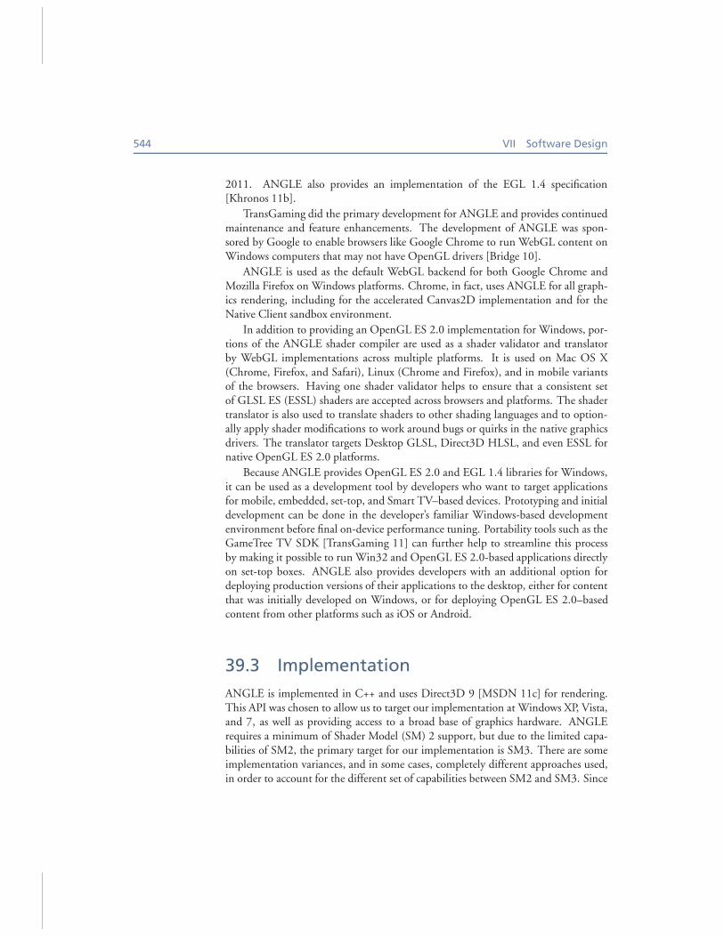
ANGLE is implemented in C++ and uses Direct3D 9 [MSDN 11c] for rendering.This API was chosen to allow us to target our implementation at Windows XP, Vista,and 7, as well as providing access to a broad base of graphics hardware. ANGLErequires a minimum of Shader Model (SM) 2 support, but due to the limited capa-bilities of SM2, the primary target for our implementation is SM3. There are someimplementation variances, and in some cases, completely different approaches used,in order to account for the different set of capabilities between SM2 and SM3. Since
39. The ANGLE Project: Implementing OpenGL ES 2.0 on Direct3D 545
SM3 is our primary target, the focus of this chapter is on the description of ourimplementation for this feature set.
The main challenge of implementing OpenGL ES on top of another graphicsAPI, such as Direct3D, is accounting for different conventions and capabilities. Somedifferences can be implemented in a straightforward manner, while others are muchmore involved.
This section begins with one of the most well-known differences between theAPIs: the differences in coordinate conventions. Dealing with these in a mathemat-ically sound manner is critical to achieving correct results. Next, we cover anotherkey aspect of the project: the translation of OpenGL ES shaders into their Direct3Dequivalents. Following this, we delve into handling data resources such as vertexbuffers and textures. Finally, we cover the finer details of the different API paradigmsand interfaces, tying the individual aspects into a complete OpenGL ES implemen-tation on top of Direct3D.
39.3.1 Coordinate Systems
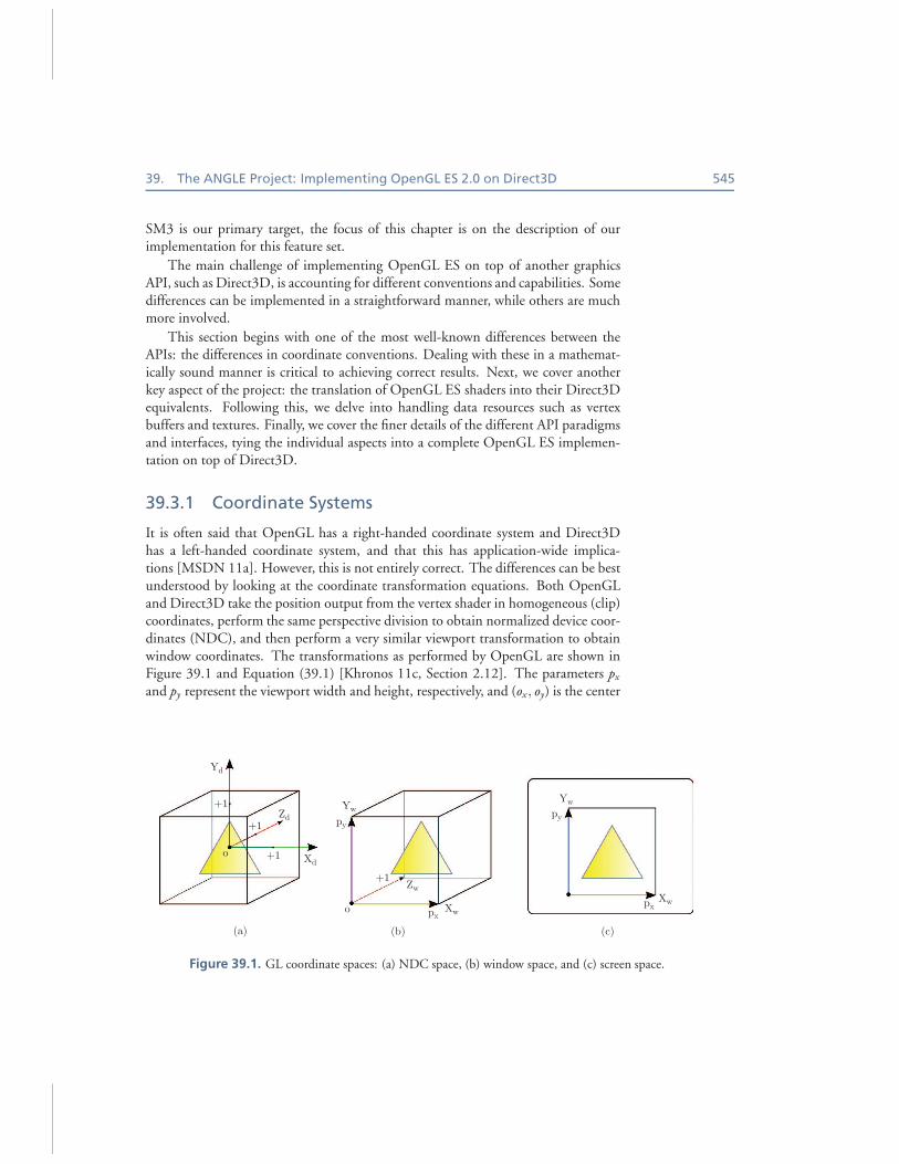
It is often said that OpenGL has a right-handed coordinate system and Direct3Dhas a left-handed coordinate system, and that this has application-wide implica-tions [MSDN 11a]. However, this is not entirely correct. The differences can be bestunderstood by looking at the coordinate transformation equations. Both OpenGLand Direct3D take the position output from the vertex shader in homogeneous (clip)coordinates, perform the same perspective division to obtain normalized device coor-dinates (NDC), and then perform a very similar viewport transformation to obtainwindow coordinates. The transformations as performed by OpenGL are shown inFigure 39.1 and Equation (39.1) [Khronos 11c, Section 2.12]. The parameters px
and py represent the viewport width and height, respectively, and (ox, oy) is the center
Yd
Zd
YwYw
Zw
Xw
py
px
Xwpx
py
Xd+1
+1
+1
o
+1
o
(a) (b) (c)
Figure 39.1. GL coordinate spaces: (a) NDC space, (b) window space, and (c) screen space.
546 VII Software Design
of the viewport (all measured in pixels):
xc
yc
zc
wc
vertex shader
clip coords
→
xd
yd
zd
=
xc/wc
yc/wc
zc/wc
perspective division
NDC coords
→ (39.1)
xw
yw
zw
=
px
2 xd + oxpy
2 yd + oyf −n
2zd +
n+f2
viewport transform
window coords
→
(
xs
ys
)
=
(
xw + xpos
yw + ypos
)
present transform
screen coords
.
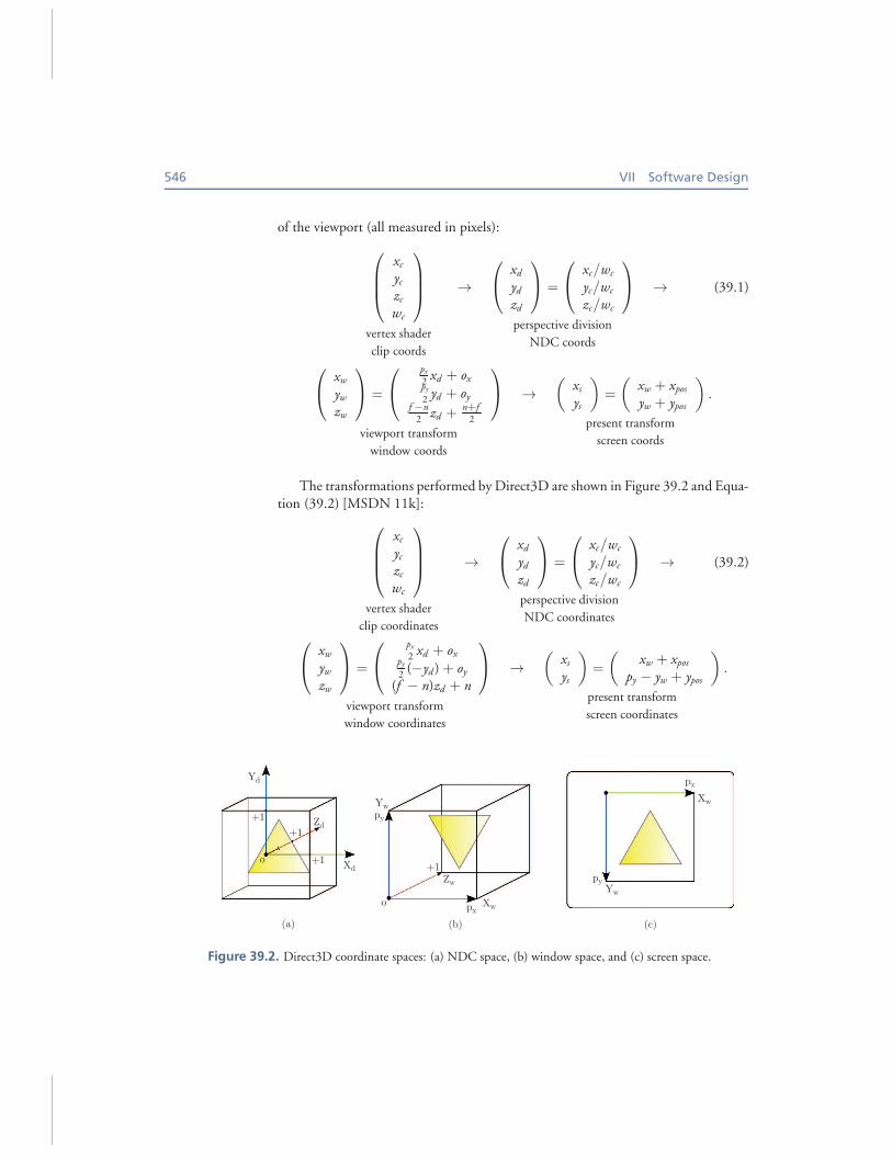
The transformations performed by Direct3D are shown in Figure 39.2 and Equa-tion (39.2) [MSDN 11k]:
xc
yc
zc
wc
vertex shader
clip coordinates
→
xd
yd
zd
=
xc/wc
yc/wc
zc/wc
perspective division
NDC coordinates
→ (39.2)
xw
yw
zw
=
px
2 xd + oxpy
2 (−yd ) + oy
(f − n)zd + n
viewport transform
window coordinates
→
(
xs
ys
)
=
(
xw + xpos
py − yw + ypos
)
present transform
screen coordinates
.
Yd
Zd
YwXw
Zw
Xw
py
px
Yw
py
px
Xd+1
+1
+1
o+1
o
(a) (b) (c)
Figure 39.2. Direct3D coordinate spaces: (a) NDC space, (b) window space, and (c) screen space.
39. The ANGLE Project: Implementing OpenGL ES 2.0 on Direct3D 547
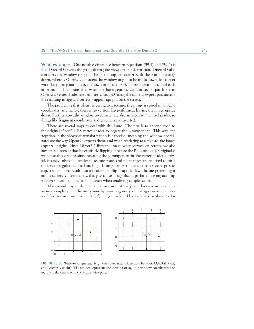
Window origin. One notable difference between Equations (39.1) and (39.2) isthat Direct3D inverts the y-axis during the viewport transformation. Direct3D alsoconsiders the window origin to be in the top-left corner with the y-axis pointingdown, whereas OpenGL considers the window origin to be in the lower-left cornerwith the y-axis pointing up, as shown in Figure 39.3. These operations cancel eachother out. This means that when the homogeneous coordinates output from anOpenGL vertex shader are fed into Direct3D using the same viewport parameters,the resulting image will correctly appear upright on the screen.
The problem is that when rendering to a texture, the image is stored in windowcoordinates, and hence, there is no vertical flip performed, leaving the image upsidedown. Furthermore, the window coordinates are also an input to the pixel shader, sothings like fragment coordinates and gradients are inverted.
There are several ways to deal with this issue. The first is to append code tothe original OpenGL ES vertex shader to negate the y-component. This way, thenegation in the viewport transformation is canceled, meaning the window coordi-nates are the way OpenGL expects them, and when rendering to a texture, the imageappears upright. Since Direct3D flips the image when viewed on screen, we alsohave to counteract that by explicitly flipping it before the Present call. Originally,we chose this option; since negating the y-component in the vertex shader is triv-ial, it easily solves the render-to-texture issue, and no changes are required to pixelshaders or regular texture handling. It only comes at the cost of an extra pass tocopy the rendered result into a texture and flip it upside down before presenting iton the screen. Unfortunately, this pass caused a significant performance impact—upto 20% slower—on low-end hardware when rendering simple scenes.
The second way to deal with the inversion of the y-coordinate is to invert thetexture sampling coordinate system by rewriting every sampling operation to usemodified texture coordinates: (s′, t ′) = (s, 1 − t). This implies that the data for
4
3
2
1
0
3
2
1
0
0 1 2 3 4
0 1 2
(ox, oy)(ox, oy)
3 4 5
Figure 39.3. Window origin and fragment coordinate differences between OpenGL (left)and Direct3D (right). The red dot represents the location of (0, 0) in window coordinates and(ox, oy) is the center of a 5 × 4 pixel viewport.
548 VII Software Design
regular textures must be stored in an upside down fashion. Cube maps are handledby additionally swapping the top (+Y) and bottom (−Y) faces. It also requires allpixel shader operations that use the window y-coordinate to be adjusted. This isthe solution currently implemented and is discussed further in Section 39.3.2. Thetexture inversions on upload are a potential source of inefficiency, but we alreadyswizzle and convert most texture data on load, so this does not add additional over-head. Another concern is that the modification of the texture coordinates turns theminto dependent texture reads. This could prevent prefetching of texture data on someGPU architectures, and the extra instructions add computational overhead. Fortu-nately, this does not appear to be a problem on most desktop GPUs, and we havenot observed negative effects due to these modifications.
The third way of solving this issue is to invert the rendering only when renderinginto a texture and using the shader unmodified when rendering to a window. Thisapproach could avoid the drawbacks of the first two methods, but it is not with-out additional implementation complexity. The shaders would have to be compileddifferently depending on the rendering destination and it could also affect the fillconvention. This approach is still under evaluation and might be implemented inthe future.
Winding order. Another interesting consequence of the difference in viewporttransformations between OpenGL and Direct3D is that the winding order of a tri-angle’s vertices is reversed. The winding order determines whether a triangle is con-sidered front facing or back facing and hence which primitives are culled. Since thewinding order is computed using window coordinates, the need to invert the cullingparameters also depends on whether or not the viewport transformation difference ishandled in the vertex shader.
Dithering. No specific dithering algorithm is required in OpenGL ES, only thatthe dithering algorithm depends solely on the fragment’s value and window coor-dinates. When the viewport is inverted, this has the potential to make the dither-ing algorithm also depend on the viewport height. However, if the identity func-tion is used, this dithering requirement is trivially fulfilled. Direct3D 9 does havea D3DRS DITHERENABLE render state, but dithering is typically no longer directlysupported on recent hardware.
Fill convention. One last interesting effect of the different viewport transforma-tions is that it also affects the fill convention. The fill convention is the rule thatdecides whether a pixel whose center is directly on a triangle’s edge is considered cov-ered by that triangle or not. This is vital to prevent adjoining triangles from fillingthe same pixels twice or leaving gaps. Direct3D enforces a top-left fill convention.OpenGL does not require a specific fill convention, only that a well-defined conven-tion is used consistently. Although ANGLE complies with this, it is worth notingthat the OpenGL specification does not guarantee exact pixel results. In particular,
39. The ANGLE Project: Implementing OpenGL ES 2.0 on Direct3D 549
screen-space rectangles should be aligned to pixel edges instead of pixel centers toavoid unexpected results.
Depth range. In addition to the window-origin differences, there is also a differ-ence in the depth range of the homogeneous coordinates that must be accounted for.OpenGL clips the z-coordinate to the [−1, 1] range and then transforms it to the[near, far] range specified with glDepthRangef. Direct3D uses the [0, 1] rangeinstead. Note again that, contrary to popular belief, the z-axis of OpenGL doesnot point out of the screen. Both OpenGL and Direct3D applications are free touse whichever coordinate system(s) they prefer, as long as the projection takes careof correctly transforming the camera-space coordinates into the intended clip-spacecoordinates. Since clipping takes place right after the vertex shader stage, we can ac-count for the differences by appending code to the original vertex shader that adjuststhe output z-coordinate. We will revisit this in Section 39.3.2.
Fragment coordinates. The numerical coordinates for pixel centers are also dif-ferent between OpenGL and Direct3D 9. In OpenGL, the pixel centers are locatedat half-pixel locations, and thus, the (x, y) fragment coordinate of the pixel closest tothe origin is (0.5, 0.5). In Direct3D 9, pixel centers are located at integral locations,and the location of the pixel closest to the origin is (0, 0). This also means that view-ports are not symmetric around the origin, as shown in Figure 39.3. This oddity hasbeen corrected in Direct3D 10, but for ANGLE on Direct3D 9, a half-pixel offset isrequired to adjust the fragment coordinates for this difference. This adjustment canalso be done at the output of the vertex shader stage, so in homogeneous coordinates,the half-pixel offset becomes ( 1
pxwc,
1py
wc).
39.3.2 Shader Compiler and Linker
The initial design of the OpenGL Shading Language was done by 3Dlabs. As partof their work, they developed and released an open-source GLSL compiler front-end and shader validator for the initial version of GLSL [3Dlabs 05]. This GLSLcompiler front-end was used as the starting point for ANGLE’s shader compiler andtranslator. The 3Dlabs compiler front-end was designed for Version 1.10 of theGLSL specification and thus needed to be adapted for the GLSL ES Version 1.00language [Khronos 11e]. The differences between GLSL 1.10 and GLSL ES 1.00are summed up in a student report from the Norwegian University of Science andTechnology [Ek 05].
Architecture. In OpenGL ES 2.0, individual vertex and fragment shaders arecompiled using glCompileShader and linked into a single program using glLinkProgram. With Direct3D 9, however, there is no explicit linking step between thevertex and pixel shaders (the Direct3D equivalent of the ESSL fragment shader).Vertex shader outputs and pixel shader inputs have to be assigned a “semantic”[MSDN 11j], essentially a register identifier, within the HLSL code itself, and they
550 VII Software Design
are implicitly linked when the shaders are made active. Since assigning matchingsemantics can only be done when both the vertex and pixel shaders are known, theactual HLSL compilation has to be deferred until link time. During the compilationcall, ANGLE can only translate the ESSL code into HLSL code, leaving the out-put and input declarations blank. Note that this is not unique to ANGLE, as otherOpenGL and OpenGL ES implementations also defer some of the compilation untillink time.
The ANGLE shader compiler component functions as either a translator or avalidator. It consists of two main components: the compiler front-end and the com-piler back-end. The compiler front-end consists of the preprocessor, lexer, parser,and abstract syntax tree (AST) generator. The lexer and parser are generated fromthe shading language grammar using the flex [Flex 08] and bison [FSF 11] tools.The compiler back-end consists of several output methods that convert the AST to adesired form of ‘object’ code. The forms of object code that are currently supportedare the HLSL, GLSL, or ESSL shader strings. The shader compiler can validateshaders against either the ESSL specification [Khronos 11e] or the WebGL specifica-tion [Khronos 11f]. ANGLE uses the former, and the web browsers use the latter.
During program object linking, the translated HLSL shaders from the “com-piled” vertex and fragment shaders are compiled into binary shader blobs. The shaderblobs include both the Direct3D 9 bytecode for the shaders and the semantic infor-mation required to map uniforms to constants. The D3DXGetShaderConstant
Table method is used to obtain the uniform information and define the mappingsbetween the uniform names and the vertex and pixel shader constant locations. Notethat ANGLE uses the Direct3D 10 shader compiler instead of the one included withD3DX9 because it comes as a separately updated DLL, produces superior shader as-sembly/binary code, and can handle complex shaders more successfully without run-ning out of registers or instruction slots. Unfortunately, there are still some shadersthat contain complex conditionals or loops with a high number of iterations that failto compile even with the Direct3D 10 compiler.
Shader translation. The translation of ESSL into HLSL is achieved by traversingthe AST and converting it back into a textual representation while taking the differ-ences between the languages into account. The AST is a tree structure representationof the original source code, so the basic process of turning each node into a stringis relatively straightforward. We also extended 3Dlabs’ definition of the AST andtheir traversing framework to preserve additional source information like variabledeclarations and precisions.
HLSL supports the same binary and unary operators as ESSL, but there aresome noteworthy differences in semantics. In ESSL, the first matrix componentsubscript accesses a column vector while the second subscript (if any) selects the row.With HLSL, this order is reversed. Furthermore, OpenGL constructs matrices fromelements specified in column-major order while Direct3D uses row-major order.These differences were addressed by transposing matrix uniforms. This also required

39. The ANGLE Project: Implementing OpenGL ES 2.0 on Direct3D 551
(un-)transposing matrices when used in binary operations. Although it may seem in-efficient to transpose matrices within the HLSL shader, at the assembly level it simplyresults in having multiply-add vector instructions instead of dot-product instructionsor vice versa. No noticeable performance impact was observed.
Another significant semantic difference between the two languages is the eval-uation of the ternary select operator (cond ? expr1 : expr2). With HLSL,both expressions are evaluated, and then the result of one of them is returned basedon the condition. ESSL adheres to the C semantics and only evaluates the expressionthat is selected by the condition. To achieve the ESSL semantics with HLSL, ternaryoperators are rewritten as if/else statements. Because ternary operators can be nestedand statements can contain multiple ternary operators, we implemented a separateAST traverser that hierarchically expands the ternary operators and assigns the re-sults to temporary variables that are then used in the original statement containingthe ternary operator. The logical binary Boolean AND (&&) and OR (‖) operatorsalso require short-circuited evaluation and can be handled in a similar manner.
To prevent temporary variables and differences in intrinsic function names fromcolliding with names used in the ESSL source, we “decorate” user-defined ESSLnames with an underscore. Reserved names in the ESSL code use the same gl
prefix in HLSL, while variables needed to implement or adjust for Direct3D-specificbehavior have a dx prefix.
Shader built-ins. The OpenGL ES shading language provides a number of built-in shader variables, inputs, and functions that are not directly provided by Direct3D’sHLSL or that require different semantics between the two languages.
The vertex shading language has no built-in inputs but instead supportsapplication-defined attribute variables that provide the values passed into a shaderon a per-vertex basis. The attributes are mapped directly to HLSL vertex shaderinputs using the TEXCOORD[#] semantics.
The varying variables form the interface between the vertex and fragment shaders.ESSL has no built-in varying variables and supports only application-defined vary-ings. These varyings are mapped to HLSL vertex shader outputs and pixel shaderinputs using the COLOR[#] semantics. In most cases, we could alternatively use theTEXCOORD[#] semantics, but these are treated differently for point-sprite rendering,so instead, we always use the COLOR[#] semantics for user-defined varyings. Theexception for this is in SM2, where variables with the COLOR[#] semantics have lim-ited range and precision, and thus we must use the TEXCOORD[#] semantic. For thisreason, we cannot directly support large points when using SM2.
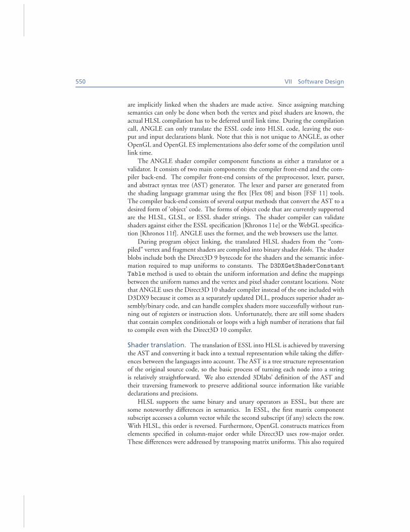
The vertex shading language has two built-in output variables: gl PointSize
and gl Position. The gl PointSize output controls the size at which a point israsterized. This is equivalent to the HLSL vertex shader PSIZE output semantic, butto meet the GL requirements, it must be clamped to the valid point size range. Thegl Position output determines the vertex position in homogeneous coordinates.This is similar to the HLSL vertex shader POSITION0 output semantic; however, we
552 VII Software Design
output.gl_PointSize = clamp(gl_PointSize , 1.0, ALIASED_POINT_SIZE_RANGE_MAX_SM3);
output.gl_Position.x = gl_Position.x - dx_HalfPixelSize.x * gl_Position.w;output.gl_Position.y = gl_Position.y - dx_HalfPixelSize.y * gl_Position.w;
output.gl_Position.z = (gl_Position.z + gl_Position.w) * 0.5;output.gl_Position.w = gl_Position.w;output.gl_FragCoord = gl_Position;
Listing 39.1. Vertex shader epilogue.
must account for several differences between Direct3D and OpenGL coordinates atthis point before we can use it. As described previously in Section 39.3.1, the x- andy-coordinates are adjusted by the half-pixel offset in screen space to account for thefragment coordinate differences, and the z-coordinate is adjusted to account for thedepth-range differences. Listing 39.1 shows the vertex shader epilogue that convertsthe ESSL shader to Direct3D semantics.
The fragment shading language has three built-in read-only variables: gl Frag
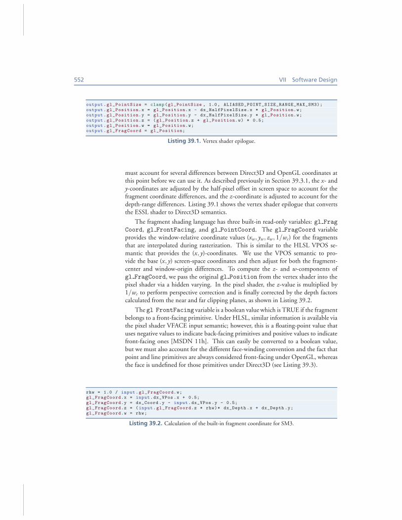
Coord, gl FrontFacing, and gl PointCoord. The gl FragCoord variableprovides the window-relative coordinate values (xw, yw, zw, 1/wc) for the fragmentsthat are interpolated during rasterization. This is similar to the HLSL VPOS se-mantic that provides the (x, y)-coordinates. We use the VPOS semantic to pro-vide the base (x, y) screen-space coordinates and then adjust for both the fragment-center and window-origin differences. To compute the z- and w-components ofgl FragCoord, we pass the original gl Position from the vertex shader into thepixel shader via a hidden varying. In the pixel shader, the z-value is multiplied by1/wc to perform perspective correction and is finally corrected by the depth factorscalculated from the near and far clipping planes, as shown in Listing 39.2.
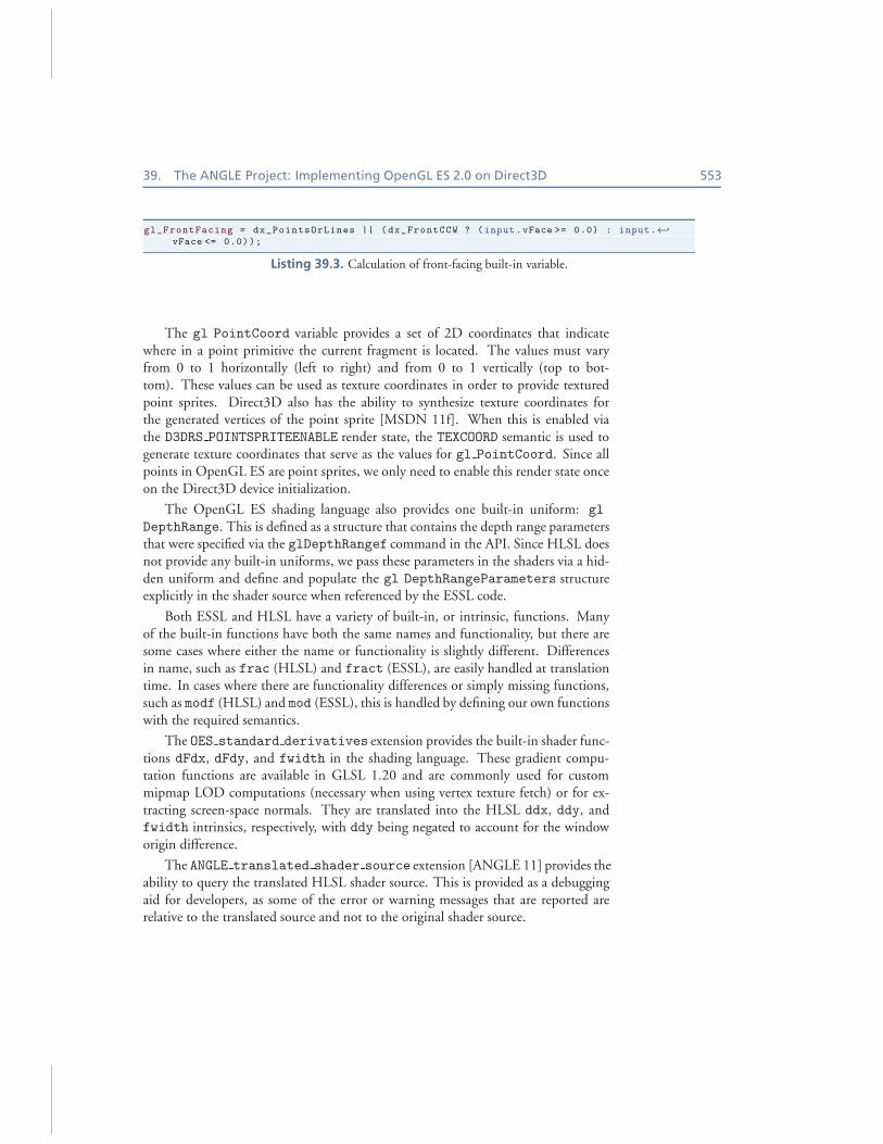
The gl FrontFacing variable is a boolean value which is TRUE if the fragmentbelongs to a front-facing primitive. Under HLSL, similar information is available viathe pixel shader VFACE input semantic; however, this is a floating-point value thatuses negative values to indicate back-facing primitives and positive values to indicatefront-facing ones [MSDN 11h]. This can easily be converted to a boolean value,but we must also account for the different face-winding convention and the fact thatpoint and line primitives are always considered front-facing under OpenGL, whereasthe face is undefined for those primitives under Direct3D (see Listing 39.3).
rhw = 1.0 / input.gl_FragCoord.w;gl_FragCoord.x = input.dx_VPos .x + 0.5;
gl_FragCoord.y = dx_Coord .y - input.dx_VPos .y - 0.5;gl_FragCoord.z = (input.gl_FragCoord.z * rhw)* dx_Depth .x + dx_Depth .y;
gl_FragCoord.w = rhw;
Listing 39.2. Calculation of the built-in fragment coordinate for SM3.
39. The ANGLE Project: Implementing OpenGL ES 2.0 on Direct3D 553
gl_FrontFacing = dx_PointsOrLines || (dx_FrontCCW ? (input.vFace >= 0.0) : input.←֓
vFace <= 0.0));
Listing 39.3. Calculation of front-facing built-in variable.
The gl PointCoord variable provides a set of 2D coordinates that indicatewhere in a point primitive the current fragment is located. The values must varyfrom 0 to 1 horizontally (left to right) and from 0 to 1 vertically (top to bot-tom). These values can be used as texture coordinates in order to provide texturedpoint sprites. Direct3D also has the ability to synthesize texture coordinates forthe generated vertices of the point sprite [MSDN 11f]. When this is enabled viathe D3DRS POINTSPRITEENABLE render state, the TEXCOORD semantic is used togenerate texture coordinates that serve as the values for gl PointCoord. Since allpoints in OpenGL ES are point sprites, we only need to enable this render state onceon the Direct3D device initialization.
The OpenGL ES shading language also provides one built-in uniform: gl
DepthRange. This is defined as a structure that contains the depth range parametersthat were specified via the glDepthRangef command in the API. Since HLSL doesnot provide any built-in uniforms, we pass these parameters in the shaders via a hid-den uniform and define and populate the gl DepthRangeParameters structureexplicitly in the shader source when referenced by the ESSL code.
Both ESSL and HLSL have a variety of built-in, or intrinsic, functions. Manyof the built-in functions have both the same names and functionality, but there aresome cases where either the name or functionality is slightly different. Differencesin name, such as frac (HLSL) and fract (ESSL), are easily handled at translationtime. In cases where there are functionality differences or simply missing functions,such as modf (HLSL) and mod (ESSL), this is handled by defining our own functionswith the required semantics.
The OES standard derivatives extension provides the built-in shader func-tions dFdx, dFdy, and fwidth in the shading language. These gradient compu-tation functions are available in GLSL 1.20 and are commonly used for custommipmap LOD computations (necessary when using vertex texture fetch) or for ex-tracting screen-space normals. They are translated into the HLSL ddx, ddy, andfwidth intrinsics, respectively, with ddy being negated to account for the windoworigin difference.
The ANGLE translated shader source extension [ANGLE 11] provides theability to query the translated HLSL shader source. This is provided as a debuggingaid for developers, as some of the error or warning messages that are reported arerelative to the translated source and not to the original shader source.
554 VII Software Design
39.3.3 Vertex and Index Buffers
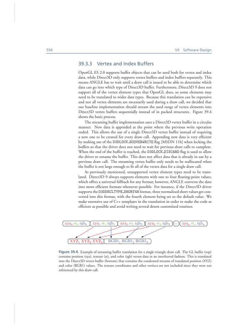
OpenGL ES 2.0 supports buffer objects that can be used both for vertex and indexdata, while Direct3D only supports vertex buffers and index buffers separately. Thismeans ANGLE has to wait until a draw call is issued to be able to determine whichdata can go into which type of Direct3D buffer. Furthermore, Direct3D 9 does notsupport all of the vertex element types that OpenGL does, so some elements mayneed to be translated to wider data types. Because this translation can be expensiveand not all vertex elements are necessarily used during a draw call, we decided thatour baseline implementation should stream the used range of vertex elements intoDirect3D vertex buffers sequentially instead of in packed structures. Figure 39.4shows the basic process.
The streaming buffer implementation uses a Direct3D vertex buffer in a circularmanner. New data is appended at the point where the previous write operationended. This allows the use of a single Direct3D vertex buffer instead of requiringa new one to be created for every draw call. Appending new data is very efficientby making use of the D3DLOCK NOOVERWRITE flag [MSDN 11b] when locking thebuffers so that the driver does not need to wait for previous draw calls to complete.When the end of the buffer is reached, the D3DLOCK DISCARD flag is used to allowthe driver to rename the buffer. This does not affect data that is already in use by aprevious draw call. The streaming vertex buffer only needs to be reallocated whenthe buffer is not large enough to fit all of the vertex data for a single draw call.
As previously mentioned, unsupported vertex element types need to be trans-lated. Direct3D 9 always supports elements with one to four floating-point values,which offers a universal fallback for any format; however, ANGLE converts the datainto more efficient formats whenever possible. For instance, if the Direct3D driversupports the D3DDECLTYPE SHORT4N format, three normalized short values get con-verted into this format, with the fourth element being set to the default value. Wemake extensive use of C++ templates in the translation in order to make the code asefficient as possible and avoid writing several dozen customized routines.
xyz0 st0 rgb0 xyz1 st1 rgb1 xyz2 st2 rgb2 xyzn stn rgbn ...
XYZ1 XYZ2 XYZ3 RGB11 RGB12 RGB13
xyz3 st3 rgb3
Figure 39.4. Example of streaming buffer translation for a single-triangle draw call. The GL buffer (top)contains position (xyz), texture (st), and color (rgb) vertex data in an interleaved fashion. This is translatedinto the Direct3D vertex buffer (bottom) that contains the condensed streams of translated position (XYZ)
and color (RGB1) values. The texture coordinates and other vertices are not included since they were notreferenced by this draw call.
39. The ANGLE Project: Implementing OpenGL ES 2.0 on Direct3D 555
Despite these optimizations, the streaming implementation is not optimal. Whendrawing the same geometry multiple times, the same data must be resent to the hard-ware on each draw call. To improve on this, ANGLE also features a static bufferimplementation. When the data in a GL buffer is not modified between draw calls,we can reuse the same Direct3D data from the previous draw call that used thisbuffer. This is achieved by associating a Direct3D vertex buffer with each OpenGLbuffer. Instead of streaming data into the global circular vertex buffer, it is streamedinto the static buffer on the first use. A cache keeps track of which vertex elementformats are stored in the static buffer and at which offset. The static buffer getsinvalidated when the OpenGL buffer is subsequently modified or when some for-mats specified by glVertexAttribPointer no longer match those in the cache.ANGLE takes the buffer usage parameter into account when determining whetheror not to initially attempt to place data in a static buffer. In our testing, we have alsofound that some applications set the usage flags incorrectly. Thus, we track whethera nonstatic buffer remains unmodified for a number of uses so it can be heuristicallypromoted to a static buffer if appropriate. Still, we recommend that applications usethe GL STATIC DRAW hint whenever they are certain a buffer will not be modifiedafter its first use in a draw call.
In addition to vertex array data specified via glVertexAttribPointer,OpenGL also supports current attribute values, i.e., attributes that remain constantduring a draw call. Direct3D does not have a similar concept. Even though the valuestays constant per draw call, using an actual Direct3D vertex shader constant wouldbe complicated because, in one draw call, an attribute can be specified by a vertexarray attribute while, in another draw call, it can use the current attribute, and thatwould require rewriting the Direct3D shader. Instead, we opted to implement cur-rent vertex attributes by using vertex buffers with only one element and a stride ofzero. When the current attribute value is modified, a whole new Direct3D buffer iscreated because some drivers do not correctly support updating dynamic buffers thatare used with a stride of zero.
ANGLE supports the OES element index uint extension, which providesthe ability to use 32-bit unsigned integer index buffers with glDrawElements.Without this extension, OpenGL ES only supports 8- and 16-bit unsigned indices.
39.3.4 Textures
There are some fundamental texture handling differences between OpenGL and Di-rect3D. In Direct3D 9, the texture format, usage, and shape (number of mipmaps)must all be declared at texture-object creation time and cannot change over the life-time of the object. In OpenGL, textures are defined one level at a time and in anylevel order; the usage is not known in advance, and the shape can change over timeas mipmaps are added. Furthermore, any or all levels of a texture can be redefined atany time with the glTexImage2D or glCopyTexImage2D commands.
556 VII Software Design
In order to handle the differences between Direct3D and OpenGL textures, theapplication-provided data for each level are stored in a system memory surface. Thecreation of the Direct3D texture is deferred until draw time when the shape and us-age of the texture are known. At Direct3D texture creation time, we must choosewhether the texture will be renderable or not. Under OpenGL, any texture canbecome renderable simply by attaching it to a framebuffer object. Creating all Di-rect3D textures as render targets can result in degraded performance and can leadto early out-of-memory situations since render target textures are typically pinnedto video memory and the driver is unable to page them out to system memory asnecessary. Since many textures are never used as render targets, the Direct3D tex-tures are created nonrenderable by default and are loaded with data from the sys-tem memory surfaces. This allows the driver to more effectively manage the texturememory. As a consequence of this, whenever a renderable version of a GL texture isrequired, we create a renderable Direct3D texture and migrate any existing data fromeither the nonrenderable Direct3D texture or from the system memory surfaces intothe renderable texture. We retain the system memory surfaces, which contain theapplication-provided texture data, as these continue to serve as staging areas for tex-ture updates via glTexSubImage2D. The system memory surfaces are also used toavoid reading back texture data from the graphics memory in the cases where thetexture is redefined.
Texture redefinition occurs whenever the format or dimensions of level 0 of atexture are changed. When this happens, any existing Direct3D backing texturemust be discarded. Ideally, the contents of any existing mip-levels of the texture atthat point are preserved in the system memory surfaces. These mip-images shouldbe kept because it is possible for the images to be used again if the texture is laterredefined in a way that is consistent with the original data. For example, consider atexture that has four levels with sizes 8 × 8, 4 × 4, 2 × 2, and 1 × 1. If level 0 isredefined as a 2×2 image, it could be used as a single-level texture with mip-filteringdisabled. If level 0 were once again redefined as an 8× 8 image with the same formatas originally used, this would once again result in a complete texture with four levels,and levels 1 through 3 would have the same data as before. This is the behaviorimplied by the specification, but not all drivers (including some versions of ANGLE)have correctly implemented image preservation on redefinition. Hence, portableapplications should not rely on this behavior; it is recommended that redefiningtextures be avoided, as this can cause expensive reallocations inside the driver.
OpenGL has recently introduced a new texture creation mechanism that allowsthe creation of immutable textures: ARB texture storage [Khronos 11d]. TheglTexStorage command is used to create a texture with a specific format, size, andnumber of levels. Once a texture has been defined by glTexStorage, the texturecannot be redefined and can only have its data specified by the gl*SubImage2D
commands or by render-to-texture. This new texture creation API is beneficial formany drivers, as it allows them to allocate the correct amount of memory up frontwithout having to guess how many mip-levels will be provided. ANGLE supports
39. The ANGLE Project: Implementing OpenGL ES 2.0 on Direct3D 557
EXT texture storage [ANGLE 11], an OpenGL ES version of this extension,in order to provide a more efficient texture implementation. With the shape andformat of the texture known at creation time, we can immediately create a Direct3Dtexture that corresponds to the GL texture. The system memory surfaces can beomitted because we can load the application-provided texture data directly into theDirect3D9 texture, and we do not have to preserve the system memory copies of thedata because TexStorage textures are immutable. The ANGLE texture usage
extension [ANGLE 11] further provides the ability to let the implementation knowthe expected usage of a texture. When it is known that a texture will be renderedinto, the usage parameter can be specified so that the implementation will know toallocate a renderable texture.
OpenGL also has the notion of incomplete textures. This occurs when insufficientlevels of a texture are present (based on the filter state), or when the formats or sizesare inconsistent between levels. When sampled in a shader, an incomplete texturealways returns the value (R,G,B,A) = (0, 0, 0, 1). Support for incomplete texturesis implemented by creating a 1-level 1 × 1 Direct3D texture of the appropriate typethat is bound to the sampler during a draw call.
Another texture difference between OpenGL ES and Direct3D 9 is the set of tex-ture formats that are supported. In addition, OpenGL applications typically supplythe texture data in an RGB(A) format, while Direct3D uses a BGR(A) componentorder for most format types. Because of the difference in component ordering andthe limited support for the Direct3D equivalents of some of the packed formats(e.g., the 4444, 5551, and 565 variants), we expand and swizzle texture data intothe D3DFMT A8R8G8B8 format at load time. The main exceptions are the lumi-nance and luminance-alpha unsigned byte texture formats, which are loaded directlyas D3DFMT L8 and D3DFMT A8L8 textures when natively supported. While we areloading the texture data, we must also flip the texture data vertically to account forthe window coordinate differences as described earlier.
To optimize the most common texture loading operations, SSE2 optimized codeis used when supported by the CPU. Similarly, glReadPixels requires flippingthe image and swizzling the color components, but since it is not expected to be aparticularly fast function (because it waits on the GPU to finish rendering), these op-erations are not yet optimized using SSE2. However, the EXT read format bgra
extension is provided in case the application does not require the components to beswizzled.
ANGLE supports a number of extensions that provide a wider range of textureand renderbuffer formats and related capabilities. OES texture npot provides sup-port for the full complement of mipmapping, minification filters, and repeat-basedwrap modes for nonpower of two textures. 8-bit per component RGB and RGBArenderbuffers (OES rgb8 rgba8), and BGRA textures (EXT texture format
BGRA8888, EXT read format bgra) provide support for 32-bpp rendering as wellas exposing formats that do not require conversions for performance reasons. The16- and 32-bit floating-point texture formats (OES texture half float, OES

558 VII Software Design
texture float), including support for linear filtering (OES texture half
float linear, OES texture float linear), are supported in order to pro-vide more precise texture data for algorithms that require it, particularly those thatalso make use of vertex textures. The DXT1 (EXT texture compression dxt1),DXT3 (ANGLE texture compression dxt3), and DXT5 (ANGLE texture
compression dxt5) compressed texture formats [ANGLE 11] are also providedto improve performance by using less texture bandwidth in the GPU and by reduc-ing system and video memory requirements.
39.3.5 Vertex Texture Fetch
OpenGL ES 2 provides the capability to support texture sampling in vertex shaders(also referred to as vertex texture fetch or VTF) although support for this is notmandated. VTF is often used for techniques such as displacement mapping wherea heightmap is stored in a texture and then used to adjust the position of the vertexbased on the value obtained from a texture lookup. In order to determine whetherVTF is supported on a particular implementation and device combination, the ap-plication must query the MAX VERTEX TEXTURE IMAGE UNITS limit. If the valuefor this limit is zero, VTF is not supported.
The initial implementation of ANGLE did not support vertex textures; however,support was later added as this was a highly sought-after feature. The potentialdifficulty with implementing VTF in ANGLE is that some SM3 hardware has nosupport for it, and on other hardware, it is only supported in a very limited form—typically only for 2D textures with 32-bit floating-point formats and only with pointfiltering. Unlike Direct3D 9, which exposes capabilities like this at a very granularlevel, OpenGL and OpenGL ES do not provide a way to limit what types of texturesor formats can be used with vertex texturing; it is required for all textures types andformats. With OpenGL, using a format or type that is not directly supported byhardware will cause vertex processing to fall back to software. With Direct3D 9, it ispossible to get a more complete set of vertex texture capabilities by enabling softwarevertex processing [MSDN 11g], but that is not without its own drawbacks. First,the Direct3D 9 device must be created with mixed vertex processing and that maynot perform as well as a pure hardware device. Next, in order to use a texture withsoftware vertex processing, the texture must be created in the scratch memory pool[MSDN 11b], necessitating additional copies of the texture data and ensuring thatthey are all kept in sync. Finally, software vertex processing is likely to be significantlyslower, and in many cases, developers would rather do without the functionality thanhave it available but executing in a software fallback.
Unlike SM3 hardware, SM4 (Direct3D 10 capable) hardware does provide fullsupport for vertex textures for all formats, for both 2D and cube textures, and withlinear filtering. Furthermore, these capabilities are also exposed via Direct3D 9 onthis hardware. As a result, ANGLE only exposes support for vertex texture fetchwhen it detects that it is running on SM4 hardware and can provide the full com-
39. The ANGLE Project: Implementing OpenGL ES 2.0 on Direct3D 559
plement of vertex texture functionality without falling back to software vertex pro-cessing. However, even though SM4 hardware supports 16 vertex texture samplers,the Direct3D 9 API only supports four vertex texture samplers, and thus, this is themaximum supported under ANGLE.
39.3.6 Primitive Types
Both OpenGL and Direct3D provide a number of different types of rendering prim-itives. They both include primitives for rendering points; line strips and lists; andtriangle strips, fans, and lists. OpenGL ES also provides an additional primitive typethat is not available under Direct3D 9: the line loop. Line loops are similar to linestrips with the addition of a closing line segment that is drawn between the last vertexvn and the first vertex v0. Thus, for a render call with n vertices, there are n− 1 linesegments drawn between vertices (vi−1, vi)|1 ≤ i ≤ n and a final line segment be-tween vertices (vn, v0). In ANGLE, this is implemented by drawing two line strips.The first draw call, either arrayed or indexed as specified by the original drawingcommand, renders the first n − 1 line segments via a line strip. The second drawcall renders the final line segment using a streaming index buffer that contains theindices of the last and first vertex from the original draw command.
Large points and wide lines are optional capabilities in OpenGL ES 2. Supportfor these must be queried by checking the maximum available point size range andline width range. Large points are often used for particle systems or other sprite-based rendering techniques, as they have a significant memory and bandwidth savingcompared to the fallback method of drawing two triangles forming a screen-alignedquadrilateral. ANGLE supports points with sizes up to a maximum of 64 pixels inorder to support point sprite rendering. Wide lines are used less frequently and, as ofthe time of writing, ANGLE does not support lines with width larger than one.
39.3.7 Masked Clears
Another OpenGL capability not directly supported by Direct3D is masked clear op-erations. Under Direct3D 9, the color, depth, and stencil masks do not apply to clearoperations, whereas they do in OpenGL. Thus, in cases where only some of the coloror stencil components are to be cleared, we implement the clear operation by drawinga quad the size of the framebuffer. As with glClear, the scissor test limits the areathat is affected by the draw command. One of the drawbacks to implementing theclear call via a draw operation is that the current state of the Direct3D device must bemodified. Since we do significant caching in order to minimize the state setup thatmust be done at draw time, this draw command has the potential to interfere withthat caching. In order to minimize the individual state changes that must be done,we preserve the current Direct3D rendering state in a stateblock, configure the statefor the clearing draw call, perform the draw, and then restore the previous state fromthe stateblock. In cases where masked clear operations are not required, we directlyuse the Direct3D 9 Clear call for performance.
560 VII Software Design
39.3.8 Separate Depth and Stencil Buffers
Framebuffer configuration in OpenGL ES allows applications to separately spec-ify depth and stencil buffers. Depth and stencil buffers are not separable in Di-rect3D, and thus, we are not able to support arbitrary mixing of depth and stencilbuffers. However, this is not uncommon for OpenGL or other OpenGL ES imple-mentations and can be disallowed by reporting GL FRAMEBUFFER UNSUPPORTED
when separate buffers are simultaneously bound to the depth and stencil bindingpoints. In order to provide support for simultaneous depth and stencil operation, theOES packed depth stencil extension is supported in ANGLE. This extensionprovides a combined depth and stencil surface internal format (DEPTH24 STENCIL8
OES) that can be used for renderbuffer storage. In order to use simultaneous depthand stencil operations, the application must attach the same packed depth-stencilsurface to both the depth and stencil attachment points of the framebuffer object.The packed depth-stencil format is also used internally for all formats that requireonly depth or stencil components, and the Direct3D pipeline is configured so thatthe unused depth or stencil components have no effect. Note that since ANGLE doesnot yet support depth textures, packed depth-stencil textures are also not supported.
39.3.9 Synchronization
The glFlush command is required to flush the GL command stream and cause itto finish execution in finite time. The flush command is implemented in ANGLEvia Direct3D 9 event queries [MSDN 11i]. In Direct3D 9, issuing an event queryand calling GetData with the D3DGETDATA FLUSH parameter causes the commandbuffer to be flushed in the driver, resulting in the desired effect.
The glFinish command is required to block until all previous GL commandshave completed. This can also be implemented using Direct3D event queries byissuing an event query and then polling until the query result is available.
ANGLE also supports the NV fence extension in order to provide finer-grainedsynchronization than is possible with only flush and finish. Fence objects are alsoimplemented via Direct3D 9 event queries as they have very similar semantics.
39.3.10 Multisampling
ANGLE does not currently expose any EGL multisample configurations. This isnot due to any inherent technical difficulty, but rather due to lack of demand forit. Support for multisampling is provided with multisampled renderbuffers. TheANGLE framebuffer multisample extension [ANGLE 11] is a subset of theEXT framebuffer multisample extension from OpenGL. It provides a mecha-nism to attach multisampled images to framebuffer objects and resolve the multisam-pled framebuffer object into a single-sampled framebuffer. The resolve destinationcan either be another application-created framebuffer object or the window-systemprovided one.
39. The ANGLE Project: Implementing OpenGL ES 2.0 on Direct3D 561
ANGLE also provides support for copying directly from one framebuffer toanother. The ANGLE framebuffer blit extension [ANGLE 11] is a subset ofthe EXT framebuffer blit extension from OpenGL. It adds support for separatedraw- and read-framebuffer attachment points and makes it possible to copy directlybetween images attached to framebuffer objects. glBlitFramebufferANGLE isimplemented via the Direct3D 9 StretchRect function and therefore has somefurther restrictions compared to the desktop version. In particular, color conver-sions, resizing, flipping, and filtering are not supported, and only whole depth andstencil buffers can be copied. glBlitFramebufferANGLE is also used to resolvemultisample framebuffers.
39.3.11 Multiple Contexts and Resource Sharing
ANGLE supports multiple OpenGL ES contexts as well as sharing objects betweencontexts as described in Appendix C of the OpenGL ES 2.0.25 specification[Khronos 11c]. The object types that can be shared are the resource-type objects:shader objects, program objects, vertex buffer objects, texture objects, and render-buffer objects. Framebuffer objects and fences are not shareable objects. The re-quirement to share framebuffer objects was removed from the OpenGL ES 2.0.25specification in order to be more compatible with OpenGL. In general, it is notdesirable to share container-type objects, as this makes change propagation and dele-tion behavior of the shared objects difficult to specify and tricky to implementand use correctly. Furthermore, there is little value to be had from sharing con-tainer objects since they are typically quite small and have no data associated withthem.
Shared contexts are specified at context creation time via the share context
parameter to eglCreateContext. As defined in the EGL 1.4 specification, a newlycreated context will share all shareable objects with the specified share context
and, by extension, with any other contexts with which share context alreadyshares. To implement these semantics, we have a resource manager class that isresponsible for creating, tracking, and deleting all shared objects. All nonsharedobjects, framebuffers and fences, are always managed directly by the context. Theresource manager can be shared between contexts. When a new, nonshared contextis created, a new resource manager is instantiated. When a shared context is created,it acquires the resource manager from the shared context. Since contexts can be de-stroyed in any order, the resource manager is reference counted and not directly tiedto any specific context.
Direct3D 9 does not have the concept of share groups like OpenGL. It is pos-sible to share individual resources between Direct3D 9Ex devices, but this func-tionality is only supported on Windows Vista and later. Thus, in order to shareresources between ANGLE’s GL contexts, the ES and EGL implementations onlymake use of a single Direct3D 9 device object. The device is created by and associ-ated with the EGL default display and made accessible to each of the GL contexts as
562 VII Software Design
necessary. In order to provide the required separation of state between GL contexts,we must completely transition the Direct3D state when we switch GL contexts. TheeglMakeCurrent call provides us with the opportunity to do this when the currentcontext is changed. With our state-caching mechanism, we simply need to mark allour cached state dirty at this point, and the necessary Direct3D state will be set forthe next draw command.
The current GL context and corresponding EGL display are tracked using thread-local storage (TLS). The TLS is used to hold a pointer to the GL context that haslast been made current on this thread via eglMakeCurrent. When a GL functioncall is made, the current GL context for the thread is obtained from the TLS, andthe command is dispatched to the GL context. If no GL context is presently currenton the thread, the GL command is silently ignored.
ANGLE supports creation of both window- and pbuffer–based EGL surfaces.Window surfaces are implemented by creating a windowed Direct3D 9 swapchainfor the EGL surface using the HWND window handle that is passed in to eglCreate
WindowSurface as the native window. The eglSwapBuffers command mapsto the swapchain’s Present method. Window resizing is handled by recreating theswapchain. Resizing can be detected either by registering a window handler for theWM SIZE message or by checking the window size at the swap buffer’s call. The pre-ferred method is via the window handler, but this does not work for windows thatwere created in a different process. Pbuffer surfaces, which are used purely for off-screen rendering and do not need to support swapping or resizing, are implementedusing Direct3D 9 render-target textures. The eglBindTexImage API can also beused to bind a pbuffer as a texture in order to access the contents of the pbuffer.
ANGLE also supports several EGL extensions that enable more efficient inte-gration with applications that use Direct3D directly, such as a browser that uses itinternally for the compositor or video decoding. These extensions provide a mecha-nism that allows textures to be shared between ANGLE’s Direct3D device and otherDirect3D devices. This also provides the ability to share images between processessince Direct3D resources can be shared across processes. The Direct3D 9 render-target textures that back the pbuffer surfaces can either be created from, or provide,a sharing handle [MSDN 11d]. In order to make use of this, we need a mechanismto provide or extract the Direct3D share handle via EGL.
The ANGLE surface d3d texture 2d share handle extension [ANGLE11] allows an application to obtain the Direct3D share handle from an EGL sur-face. This handle can then be used in another device to create a shared texture thatcan be used to display the contents of the pbuffer. Similarly, the ANGLE d3d share
handle client buffer extension [ANGLE 11] creates a pbuffer from a Direct3Dshare handle that is specified via eglCreatePbufferFromClientBuffer. Thisprovides the ability to have ES2 content rendered into a texture that has been createdby a different Direct3D device. When sharing a surface between Direct3D devicesin different processes, it is necessary to use event queries to ensure that rendering tothe surface has completed before using the shared resource in another device. From
39. The ANGLE Project: Implementing OpenGL ES 2.0 on Direct3D 563
the ANGLE side, this can be achieved with appropriate use of a fence or by callingglFinish to ensure that the desired operations have finished.
39.3.12 Context Loss
Direct3D 9 devices can, under various scenarios, become “lost” [MSDN 11e]. OnWindows XP, this can happen when the system has a power management event suchas entering sleep mode, or screen saver activation. On Window Vista and later, whenusing Direct3D 9Ex, device loss is much more infrequent but can still happen if thehardware hangs or when the driver is stopped [MSDN 11d]. When the device islost, resources that were located in graphics memory are lost, and rendering relatedoperations are ignored. To recover from a lost Direct3D device, the application mustrelease the video memory resources and reset the device.
Unextended OpenGL ES does not provide a mechanism to notify the applica-tion of a lost or reset device. EGL does have the EGL CONTEXT LOST error code thatcorresponds to the loss of a hardware device. By default, when a device loss occurs,ANGLE generates an out-of-memory error on GL calls, and the context-lost erroron EGL calls, to indicate that the context is in an undefined state. In both cases,the proper response is to destroy all the GL contexts, recreate the contexts, and thenrestore any state and objects as necessary. EGL surfaces do not need to be recreated,but their content is undefined. For details, see Section 2.6 of the EGL 1.4 specifica-tion [Khronos 11b]. WebGL applications should additionally follow the advice forHandling Context Lost [Khronos 11a].
ANGLE supports the EXT robustness extension [ANGLE 11], which is basedon the OpenGL ARB robustness extension [Khronos 11d], in order to providea better mechanism for reporting reset notifications. This extension provides aninexpensive query, glGetGraphicsResetStatusEXT, which applications can useto learn about context resets. After receiving a reset notification, the applicationshould continue to query the reset status until GL NO ERROR is returned, at whichpoint the contexts should be destroyed and recreated.
Applications must opt into receiving reset notifications at context creation timeby specifying the reset notification strategy attribute as defined in the EXT create
context robustness extension [ANGLE 11]. Note that even if an applicationdoes not opt into receiving reset notifications, or explicitly requests no reset notifi-cations, context loss and resets can still happen at any time. Applications should bemade capable of detecting and recovering from these events.
39.3.13 Resource Limits
The OpenGL ES 2.0 API is quite feature-rich; however, there are still some fea-tures that are optional or allow for wide variability between implementations. Theseinclude the number of vertex attributes, varying vectors, vertex uniform vectors,fragment uniform vectors, vertex texture image units, fragment texture image units,
564 VII Software Design
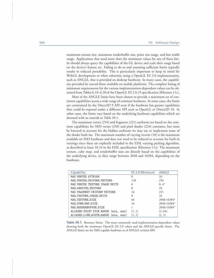
maximum texture size, maximum renderbuffer size, point size range, and line widthrange. Applications that need more than the minimum values for any of these lim-its should always query the capabilities of the GL device and scale their usage basedon the device’s feature set. Failing to do so and assuming sufficient limits typicallyresults in reduced portability. This is particularly important to keep in mind forWebGL development or when otherwise using a OpenGL ES 2.0 implementation,such as ANGLE, that is provided on desktop hardware. In many cases, the capabili-ties provided far exceed those available on mobile platforms. The complete listing ofminimum requirements for the various implementation-dependent values can be ob-tained from Tables 6.18–6.20 of the OpenGL ES 2.0.25 specification [Khronos 11c].
Most of the ANGLE limits have been chosen to provide a maximum set of con-sistent capabilities across a wide range of common hardware. In some cases, the limitsare constrained by the Direct3D 9 API even if the hardware has greater capabilitiesthat could be exposed under a different API such as OpenGL or Direct3D 10. Inother cases, the limits vary based on the underlying hardware capabilities which aredenoted with an asterisk in Table 39.1.
The maximum vertex (254) and fragment (221) uniforms are based on the com-mon capabilities for SM3 vertex (256) and pixel shader (224) constants, but mustbe lowered to account for the hidden uniforms we may use to implement some ofthe shader built-ins. The maximum number of varying vectors (10) is the maximumavailable on SM3 hardware and does not need to be reduced to account for built-invaryings since these are explicitly included in the ESSL varying packing algorithm,as described in Issue 10.16 in the ESSL specification [Khronos 11e]. The maximumtexture, cube map, and renderbuffer sizes are directly based on the capabilities ofthe underlying device, so they range between 2048 and 16384, depending on thehardware.
Capability ES 2.0 Minimum ANGLE
MAX VERTEX ATTRIBS 8 16MAX VERTEX UNIFORM VECTORS 128 254
MAX VERTEX TEXTURE IMAGE UNITS 0 0, 4*MAX VARYING VECTORS 8 10MAX FRAGMENT UNIFORM VECTORS 16 221MAX TEXTURE IMAGE UNITS 8 16
MAX TEXTURE SIZE 64 2048-16384*MAX CUBE MAP SIZE 16 2048-16384*MAX RENDERBUFFER SIZE 1 2048-16384*
ALIASED POINT SIZE RANGE (min, max) (1, 1) (1, 64)ALIASED LINE WIDTH RANGE (min, max) (1, 1) (1, 1)
Table 39.1. Resource limits. The most commonly used implementation-dependent values
showing both the minimum OpenGL ES 2.0 values and the ANGLE-specific limits. TheANGLE limits are for SM3-capable hardware as of ANGLE revision 889.
39. The ANGLE Project: Implementing OpenGL ES 2.0 on Direct3D 565
39.3.14 Optimizations
To ensure that ANGLE performs as closely as possible to a native implementationof OpenGL ES 2.0, we strive to avoid redundant or unnecessary work, both on theCPU side and on the GPU side.
Much of the effective rendering state is only known at the time of a draw call,so ANGLE defers making any Direct3D render-state changes until draw time. Forexample, Direct3D only supports explicitly setting culling for clockwise or coun-terclockwise vertex-winding orders while OpenGL indicates which winding order isconsidered front-facing by using glFrontFace. glCullFace determines whichof these sides should be culled, and GL CULL FACE enables or disables the actualculling. In theory, changing any of the glFrontFace, glCullFace, or GL CULL
FACE states would alter the corresponding Direct3D render state, but by deferringthis to the draw call, we reduce it to at most one change (per state) per draw call. Foreach related group of states, ANGLE keeps a “dirty” flag to determine whether theaffected Direct3D states should be updated.
OpenGL identifies resources by integer numbers (or “names”), while the im-plementation requires pointers to the actual objects. This means ANGLE containsseveral map containers that hold the associations between resource names and objectpointers. Since many object lookups are required per frame, this can cause a notice-able CPU hotspot. Fortunately the associations do not typically change very often,and for currently bound objects, the same name would be looked up many timesin a row. Thus, for the currently bound objects like programs and framebuffers, thepointer is cached and replaced or invalidated only when an action is performed whichmodifies the association.
ANGLE also keeps track of the textures, buffers, and shaders that are currentlyset on the Direct3D device. To avoid issues with cases where an object gets deletedand a new one coincidentally gets created at the same memory location, resources areidentified by a unique serial number instead of their pointer.
Another place caching plays a critical role in optimizing performance is in apply-ing the vertex attribute bindings. Direct3D 9 requires all attributes to be described ina vertex declaration. Creating and later disposing of this object takes up valuable timeand potentially prevents the graphics driver from minimizing internal state changes,so a cache was implemented to store the most recently used vertex declarations.
We also endeavor to minimize the GPU workload, both in terms of data transfersto/from the GPU and in terms of computational workload. As discussed earlier, wehave eliminated the overhead in flipping the rendered image at presentation time,added support for buffers with static usage, implemented mechanisms to minimizetexture reallocations, and used direct clear operations when masked clears are notrequired. We also optimize out the computation of any shader built-in variables thatare not used in the shaders.
It is important to note that while all these optimizations have made ANGLEmore complex, they have also significantly helped ensure that the underlying
566 VII Software Design
hardware, accessed through Direct3D, is used as efficiently as possible. Native driverimplementations of OpenGL and OpenGL ES also require many of the same opti-mizations and inherent complexity in order to achieve high performance in practice.
39.3.15 Recommended Practices
Throughout this chapter, we have touched on a variety of practices that should helpimprove the performance and portability of applications. While these recommenda-tions are targeted specifically at ANGLE’s implementation, we expect that many ofthese practices will also be applicable to other GL implementations:
• Always check for optional features and validate resource limits.
• Group objects in buffers based on data format (type and layout) and updatefrequency.
• Ensure that appropriate buffer usage flags are used.
• Use static buffers and fully specify the contents of buffers before draw time.
• Use separate buffers for index and vertex data.
• Use immutable textures when available. If EXT texture storage is notsupported, ensure that a complete texture is created and consistently defined.
• Avoid redefining the format or size of existing textures, and create a new tex-ture instead.
• Use the BGRA EXT / UNSIGNED BYTE texture format to minimize texture con-versions on load and for pixel readback.
• Use packed depth-stencil for combined depth and stencil support.
• Opt in to reset notifications, and handle context resets appropriately.
• Avoid masked clear operations.
• Avoid line loops by drawing closed line strips instead.
• Use fences instead of glFinish for finer synchronization control.
• Avoid using complex conditional statements and loops with a high maximumnumber of iterations in shaders.
39. The ANGLE Project: Implementing OpenGL ES 2.0 on Direct3D 567
39.3.16 Performance Results
At the time of this writing, there are no de facto benchmarks for WebGL. To correctlyinterpret performance results of applications and demos, one should first realize thatonce a draw call command reaches the GPU driver, there are, in theory, few funda-mental differences between OpenGL and Direct3D. For ANGLE, in particular, theESSL and HLSL shaders are largely equivalent, so the GPU performs essentially thesame operations. Therefore applications or demos with high numbers of vertices orhigh levels of overdraw do not really test the graphics API implementation but ratherthe hardware performance itself.
Potential differences in performance between ANGLE and native OpenGL im-plementations would stem mainly from the graphics commands issued between drawcalls (texture, buffer, and uniform updates), the setup work performed to translate aGL draw call into a Direct3D draw call, and the vertex-shader epilogue and pixel-shader prologues. Therefore, the applications and demos we chose to use for per-formance comparisons perform a relatively high number of draw calls, use varioustextures, and/or use nontrivial animations.
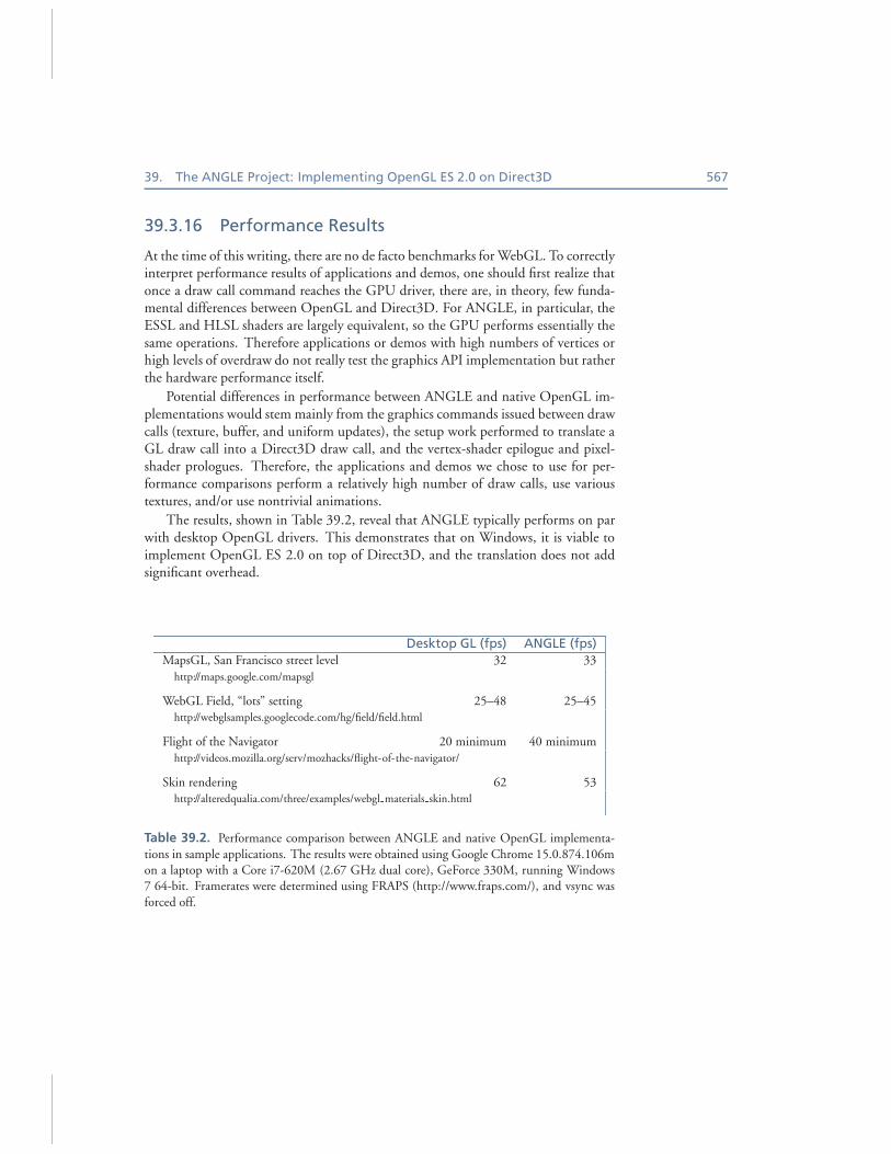
The results, shown in Table 39.2, reveal that ANGLE typically performs on parwith desktop OpenGL drivers. This demonstrates that on Windows, it is viable toimplement OpenGL ES 2.0 on top of Direct3D, and the translation does not addsignificant overhead.
Desktop GL (fps) ANGLE (fps)
MapsGL, San Francisco street level 32 33
http://maps.google.com/mapsgl
WebGL Field, “lots” setting 25–48 25–45http://webglsamples.googlecode.com/hg/field/field.html
Flight of the Navigator 20 minimum 40 minimum
http://videos.mozilla.org/serv/mozhacks/flight-of-the-navigator/
Skin rendering 62 53http://alteredqualia.com/three/examples/webgl materials skin.html
Table 39.2. Performance comparison between ANGLE and native OpenGL implementa-
tions in sample applications. The results were obtained using Google Chrome 15.0.874.106mon a laptop with a Core i7-620M (2.67 GHz dual core), GeForce 330M, running Windows7 64-bit. Framerates were determined using FRAPS (http://www.fraps.com/), and vsync was
forced off.
568 VII Software Design
39.4 Future Work
ANGLE is continuing to evolve, and there is future work to be done implementingnew features, improving performance, and resolving defects. Additional features thatcould be added include depth textures, wide lines, and multisample EGL configs.Areas for improving performance include target-dependent flipping of rendering,optimizations to texture loading and pixel readback, and bottlenecks as shown byprofiling applications. Another possible future direction for ANGLE’s developmentcould be to implement a Direct3D 11 back-end. This would allow us to supportfeatures not available in Direct3D 9, future versions of the OpenGL ES API, andfuture operating systems where Direct3D 9 is not ubiquitous.
39.5 Conclusion
This chapter explained the motivation behind ANGLE and described how it is cur-rently used in web browsers both as an OpenGL ES 2.0-based renderer and as ashader validator and translator. We discussed many of the challenging aspects ofthe implementation of this project, primarily in mapping between OpenGL andDirect3D, and explained how they were mastered. We discussed some of the opti-mizations we have made in our implementation in order to provide a conformantOpen GL ES 2.0 driver that is both competitive in performance and fully featured.The development of ANGLE is ongoing, and we welcome contributions.
39.6 Source Code
The source for the ANGLE Project is available from the Google Code repository.1
This repository includes the full source for the ANGLE libGLESv2 and libEGL li-braries as well as some small sample programs. The project can be built on Windowswith Visual C++ 2008 Express Edition or newer.
Acknowledgments We would like to acknowledge the contributions of our TransGam-
ing colleagues Shannon Woods and Andrew Lewycky, who were coimplementers of ANGLE.Thanks also to Gavriel State and others at TransGaming for initiating the project, and to Van-gelis Kokkevis and the Chrome team at Google for sponsoring and contributing extensions and
optimizations to ANGLE. Finally, we thank the Mozilla Firefox team and other communityindividuals for their contributions to the project.
1http://code.google.com/p/angleproject/
39. The ANGLE Project: Implementing OpenGL ES 2.0 on Direct3D 569
Bibliography
[3Dlabs 05] 3Dlabs. GLSL Demos and Source Code from the 3Dlabs OpenGL 2 Website. http://mew.cx/glsl/, 2005 (accessed November 27, 2011).
[ANGLE 11] ANGLE Project. ANGLE Project Extension Registry. https://code.google.com/p/angleproject/source/browse/trunk/extensions, 2011 (accessed November 27, 2011).
[Bridge 10] Henry Bridge. Chromium Blog: Introducing the ANGLE Project. http://
blog.chromium.org/2010/03/introducing-angle-project.html, March 18, 2010 (accessedNovember 27, 2011).
[Ek 05] Lars Andreas Ek, Øyvind Evensen, Per Kristian Helland, Tor Gunnar Houeland, andErik Stiklestad. “OpenGL ES Shading Language Compiler Project Report (TDT4290).”Department of Computer and Information Science at NTNU. http://www.idi.ntnu.no/emner/
tdt4290/Rapporter/2005/oglesslc.pdf, November 2005, (accessed November 27, 2011).
[FSF 11] Free Software Foundation. “Bison—GNU parser generator.” GNU Operating Sys-tem. http://www.gnu.org/s/bison/, May 15, 2011 (accessed November 27, 2011).
[MSDN 11a] Microsoft. Coordinate Systems (Direct3D 9) (Windows). http://msdn.microsoft.com/en-us/library/bb204853(VS.85).aspx, September 6, 2011 (accessed November 27,
2011).
[MSDN 11b] Microsoft. D3DUSAGE (Windows). http://msdn.microsoft.com/en-us/library/bb172625(VS.85).aspx, September 6, 2011 (accessed November 27, 2011).
[MSDN 11c] Microsoft. Direct3D 9 Graphics (Windows). http://msdn.microsoft.com/en-us/library/bb219837(VS.85).aspx, September 6, 2011 (accessed November 27, 2011).
[MSDN 11d] Microsoft. Feature Summary (Direct3D 9 for Windows Vista). http://msdn.microsoft.com/en-us/library/bb219800(VS.85).aspx, September 6, 2011 (accessedNovember 27, 2011).
[MSDN 11e] Microsoft. Lost Devices (Direct3D 9) (Windows). http://msdn.microsoft.com/en-us/library/bb174714(VS.85).aspx, September 6, 2011 (accessed November 27, 2011).
[MSDN 11f ] Microsoft. Point Sprites (Direct3D 9) (Windows). http://msdn.microsoft.com/en-us/library/bb147281(VS.85).aspx, September 6, 2011 (accessed November 27, 2011).
[MSDN 11g] Microsoft. Processing Vertex Data (Direct3D 9) (Windows). http://msdn.microsoft.com/en-us/library/bb147296(VS.85).aspx, September 6, 2011 (accessedNovember 27, 2011).
[MSDN 11h] Microsoft. ps 3.0 Registers (Windows). http://msdn.microsoft.com/en-us/library/bb172920(VS.85).aspx, September 6, 2011 (accessed November 27, 2011).
[MSDN 11i] Microsoft. Queries (DirectD9) (Windows). http://msdn.microsoft.com/en-us/library/bb147308(VS.85).aspx, September 6, 2011 (accessed November 27, 2011).
[MSDN 11j] Microsoft. Semantics (DirectX HLSL). http://msdn.microsoft.com/en-us/library/bb509647(VS.85).aspx, September 6, 2011 (accessed November 27, 2011).
[MSDN 11k] Microsoft. Viewports and Clipping (Direct3D 9) (Windows).http://msdn.microsoft.com/en-us/library/bb206341(VS.85).aspx, September 6, 2011(accessed November 27, 2011).
570 VII Software Design
[Flex 08] The Flex Project. “Flex: The Fast Lexical Analyzer.” Sourceforge. http://flex.sourceforge.net/, 2008 (accessed November 27, 2011).
[Khronos 11a] The Khronos Group. Handling Context Lost. http://www.khronos.org/webgl/wiki/HandlingContextLost, November 17, 2011 (accessed November 27, 2011).
[Khronos 11b] The Khronos Group. “Khronos Native Platform Graphics Interface (EGL
Version 1.4).” Khronos EGL API Registry. Edited by Jon Leech. http://www.khronos.org/registry/egl/specs/eglspec.1.4.20110406.pdf, April 6, 2011 (accessed November 27, 2011).
[Khronos 11c] The Khronos Group. OpenGL ES 2.0 Common Profile Specification (Version2.0.25). Edited by Aaftab Munshi and Jon Leech. http://www.khronos.org/registry/gles/specs/2.0/es full spec 2.0.25.pdf, November 2, 2010 (accessed November 27, 2011).
[Khronos 11d] The Khronos Group. OpenGL Registry. http://www.opengl.org/registry/, (ac-cessed November 27, 2011).
[Khronos 11e] The Khronos Group. “The OpenGL ES Shading Language (Version1.0.17).” Khronos OpenGL ES API Registry. Edited by Robert J. Simpson and JohnKessenich. http://www.khronos.org/registry/gles/specs/2.0/GLSL ES Specification 1.0.17.
pdf, May 12, 2009 (accessed November 27, 2011).
[Khronos 11f ] The Khronos Group. “WebGL Specification (Version 1.0).” Khronos WebGLAPI Registry. Edited by Chris Marrin. https://www.khronos.org/registry/webgl/specs/1.0/,
February 10, 2011 (accessed November 27, 2011).
[TransGaming 11] TransGaming. GameTree TV: Developers. http://gametreetv.com/
developers, 2011 (accessed November 27, 2011).