Open TX 2.1.8 How To - modelflying.co.uk Section 4... · Op Open TX Reference Section 4 2.1.7 How...
34
Op Open TX Reference Secon 4 2.1.7 How To Martin Phillips June 2016 How To...Page 1 Open TX How To ... How to Enter Bootloader Mode Page 2 How to Flash the EU LBT Firmware Page 3 How to Create a Sound File Page 7 How to Create a Text File Page 9 How to Use the Trainer Funcon Page 11 How to Record Transmier Sengs Page 15 How to Set Up a Flybarless Helicopter Page 16 How to Set Up a CCPM Helicopter Page 23 How to Create a Kill Switch Page 33 Open TX 2.1.8 How To ...
Transcript of Open TX 2.1.8 How To - modelflying.co.uk Section 4... · Op Open TX Reference Section 4 2.1.7 How...

Op
Open TX Reference Section 4
2.1.7 How To
Martin Phillips June 2016 How To...Page 1
Open TX How To ...
How to Enter Bootloader Mode Page 2
How to Flash the EU LBT Firmware Page 3
How to Create a Sound File Page 7
How to Create a Text File Page 9
How to Use the Trainer Function Page 11
How to Record Transmitter Settings Page 15
How to Set Up a Flybarless Helicopter Page 16
How to Set Up a CCPM Helicopter Page 23
How to Create a Kill Switch Page 33
Open TX 2.1.8 How To ...
Op
Open TX Reference Section 4
2.1.7 How To
Martin Phillips June 2016 How To...Page 2
Open TX How To ...
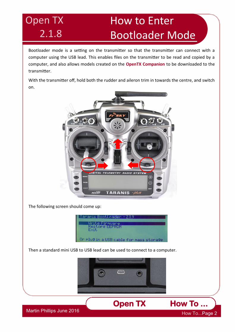
Bootloader mode is a setting on the transmitter so that the transmitter can connect with a
computer using the USB lead. This enables files on the transmitter to be read and copied by a
computer, and also allows models created on the OpenTX Companion to be downloaded to the
transmitter.
With the transmitter off, hold both the rudder and aileron trim in towards the centre, and switch
on.
The following screen should come up:
Then a standard mini USB to USB lead can be used to connect to a computer.
How to Enter Bootloader Mode
Open TX 2.1.8

Op
Open TX Reference Section 4
2.1.7 How To
Martin Phillips June 2016 How To...Page 3
Open TX How To ...
Warning: This method of flashing can only be undertaken if your transmitter uses the standard
battery. If you have replaced the standard NiMH battery with a LiPo battery, this can damage the
receiver.
1. On your computer find the copy of the SD Card (if not copy the SD card from the Taranis),
and check a sub-folder called FIRMWARES exists.
2. Go to the FrSky website http://www.frsky-rc.com/download/ and download the latest
firmware. This website screen is frequently changed, so do not assume it will look exactly
like this:
3. Above shows the XJT firmware (for the transmitter), the X4R, and the X6R/X8R. These are
the latest LBT (listen before talk) EU upgrades to meet EU regulations.
4. Go to your normal download folder, and with Windows 10, a right click on the appropriate
file will give the options to extract these files to a particular folder. Otherwise an unzip
program will be needed to unpack the files.
5. Select the FIRMWARES folder on your computer version of the SD card, and copy the XJT,
X4R and X6R/X8R to this folder.
6. These files will need to be copied to a similar folder on the actual SD card in the transmitter.
In OpenTX, with the transmitter in boot mode and connected to the computer, this can be
How to flash the EU LBT Firmware
Open TX 2.1.8
Op
Open TX Reference Section 4
2.1.7 How To
Martin Phillips June 2016 How To...Page 4
Open TX How To ...
achieved using the SD Card Synchronisation feature.
7. Next you will need to make a lead up to transfer the files. The easiest way is to use an
extension lead with plugs at one end and sockets at the other and swap the red and brown
pins at one end if using Spektrum colours, or the red and black for the Taranis telemetry
colours.
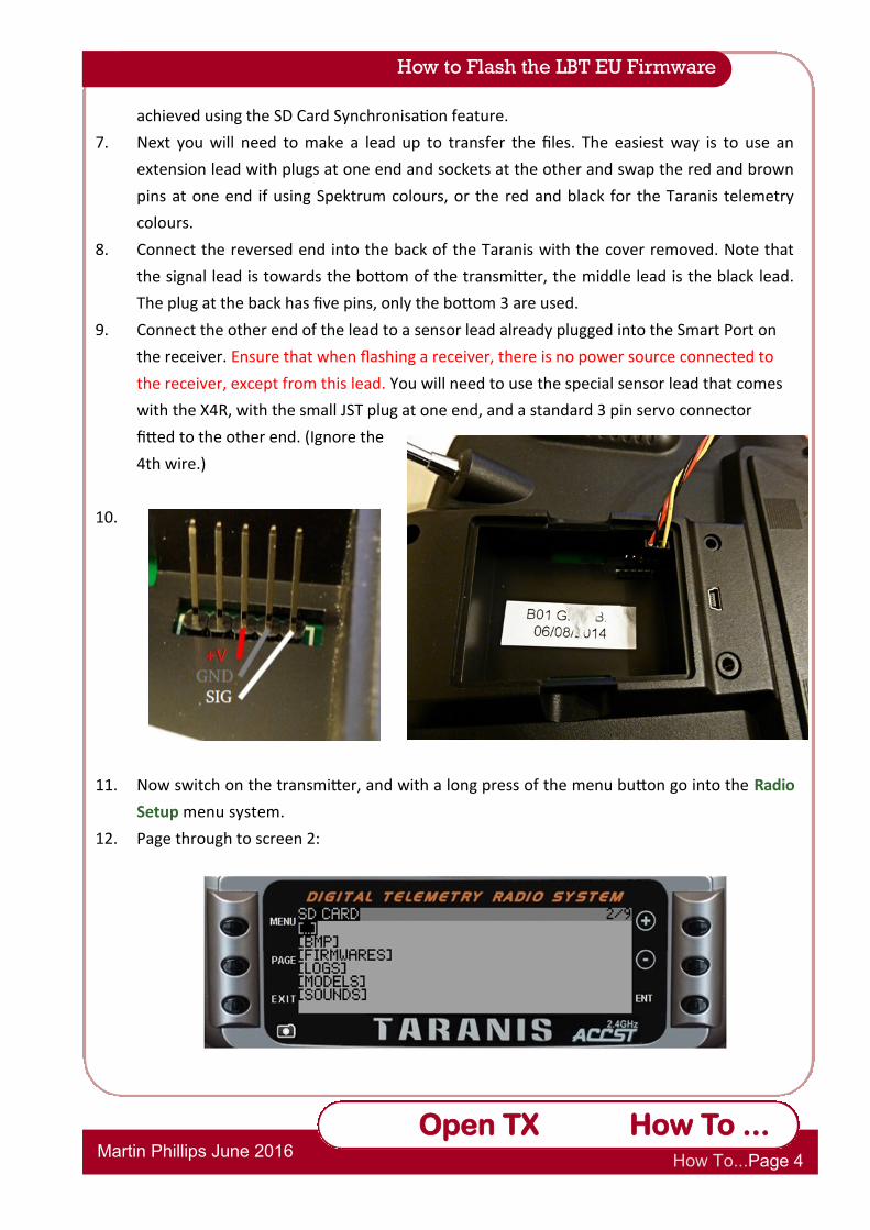
8. Connect the reversed end into the back of the Taranis with the cover removed. Note that
the signal lead is towards the bottom of the transmitter, the middle lead is the black lead.
The plug at the back has five pins, only the bottom 3 are used.
9. Connect the other end of the lead to a sensor lead already plugged into the Smart Port on
the receiver. Ensure that when flashing a receiver, there is no power source connected to
the receiver, except from this lead. You will need to use the special sensor lead that comes
with the X4R, with the small JST plug at one end, and a standard 3 pin servo connector
fitted to the other end. (Ignore the
4th wire.)
10.
11. Now switch on the transmitter, and with a long press of the menu button go into the Radio
Setup menu system.
12. Page through to screen 2:
How to Flash the LBT EU Firmware
Op
Open TX Reference Section 4
2.1.7 How To
Martin Phillips June 2016 How To...Page 5
Open TX How To ...
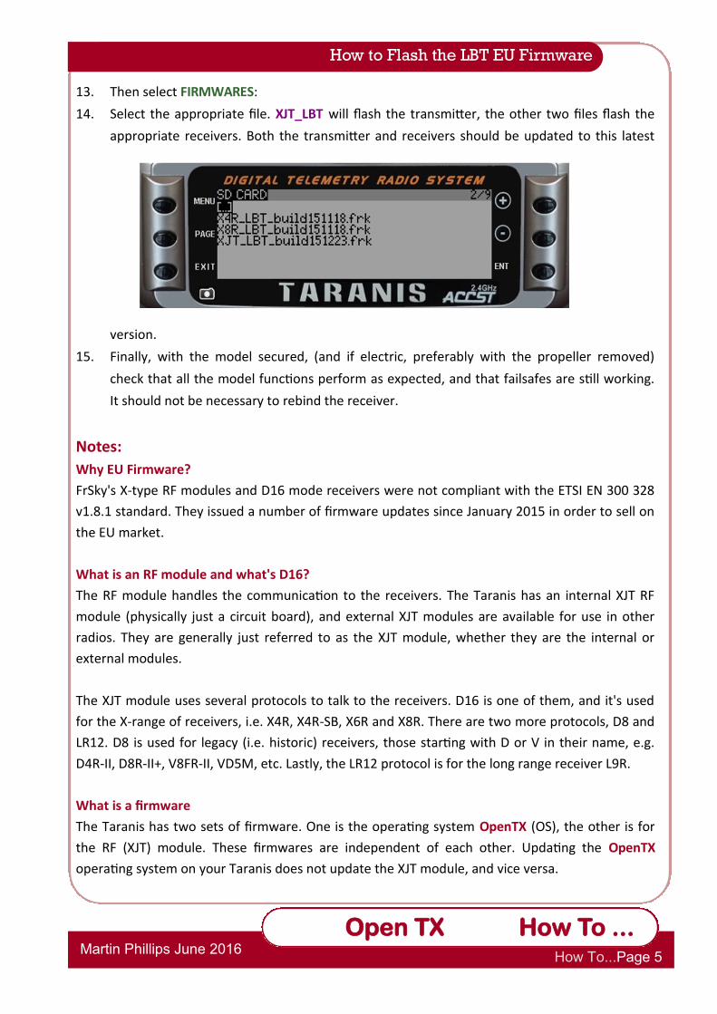
13. Then select FIRMWARES:
14. Select the appropriate file. XJT_LBT will flash the transmitter, the other two files flash the
appropriate receivers. Both the transmitter and receivers should be updated to this latest
version.
15. Finally, with the model secured, (and if electric, preferably with the propeller removed)
check that all the model functions perform as expected, and that failsafes are still working.
It should not be necessary to rebind the receiver.
Notes:
Why EU Firmware?
FrSky's X-type RF modules and D16 mode receivers were not compliant with the ETSI EN 300 328
v1.8.1 standard. They issued a number of firmware updates since January 2015 in order to sell on
the EU market.
What is an RF module and what's D16?
The RF module handles the communication to the receivers. The Taranis has an internal XJT RF
module (physically just a circuit board), and external XJT modules are available for use in other
radios. They are generally just referred to as the XJT module, whether they are the internal or
external modules.
The XJT module uses several protocols to talk to the receivers. D16 is one of them, and it's used
for the X-range of receivers, i.e. X4R, X4R-SB, X6R and X8R. There are two more protocols, D8 and
LR12. D8 is used for legacy (i.e. historic) receivers, those starting with D or V in their name, e.g.
D4R-II, D8R-II+, V8FR-II, VD5M, etc. Lastly, the LR12 protocol is for the long range receiver L9R.
What is a firmware
The Taranis has two sets of firmware. One is the operating system OpenTX (OS), the other is for
the RF (XJT) module. These firmwares are independent of each other. Updating the OpenTX
operating system on your Taranis does not update the XJT module, and vice versa.
How to Flash the LBT EU Firmware
Op
Open TX Reference Section 4
2.1.7 How To
Martin Phillips June 2016 How To...Page 6
Open TX How To ...
If you have a pre-2015 Taranis and buy new D16 mode receivers manufactured for sale in the EU,
you wouldn't be able to use them. You can't just update the OS to the latest version and expect it
to bind with your new receivers. It's important to understand the difference between the two
firmwares.
The Crucial Bit!
This is important, your XJT module and any D16 receivers must match. Either both have EU
firmwares, or both have non-EU firmwares. The D8 and LR12 mode receivers are not affected by
this choice. If you're sticking with EU firmwares, then make sure to upgrade both the XJT and D16
receivers to the LBT firmware. The latest LBT firmware (2016) fixes some issues present in older EU
firmwares.
Locked EU Transmitters
From June 2016, all new transmitters sold in the EU have to have the transmitting firmware locked
so it cannot be flashed with an earlier version. Therefore if using a mix of old and new, EU users
with new transmitters will have to use the LBT firmware. Note that this has nothing to do with the
OpenTX firmware, it is only the FrSky XJT firmware that is locked.
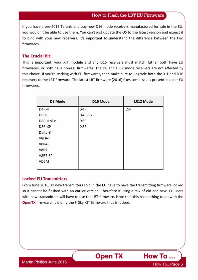
D8 Mode D16 Mode LR12 Mode
D4R-II
D6FR
D8R-II plus
D8R-XP
Delta-8
V8FR-II
V8R4-II
V8R7-II
V8R7-SP
VD5M
X4R
X4R-SB
X6R
X8R
L9R
How to Flash the LBT EU Firmware

Op
Open TX Reference Section 4
2.1.7 How To
Martin Phillips June 2016 How To...Page 7
Open TX How To ...
Sound files can be created for a variety of purposes. The can be used as warnings, for information
or to play background music. Spoken files can be created using a microphone on the computer or
a computer text-to-speech generator that will save the files. Sound files can also be spoken timed
commands. In fact a sound file can be anything from a sound effect to a full track of a song. It is
worth downloading the free Audacity program to manipulate the speech file, and get it in the
right format for OpenTX to use. It can also convert sound files to get sound levels right and
convert to mono, as OpenTx will not play stereo files correctly. Audacity can be a little
complicated, but readily usable for our basic requirements. There are different voices available in
most text-to-speech programs, and therefore these different voices can be used for different
types of messages.
Either go on line a select a text to speech program, or download one. Balabolka if it available is
quite a good program and has the added benefit that it will save in the right format for OpenTX
without having to use Audacity to convert it.
Here is a phrase to be used when the timer countdown gets to zero. It does produce the odd wry
smile down at the flying field.
Open TX
2.1.8
How to Create a
Sound File
Op
Open TX Reference Section 4
2.1.7 How To
Martin Phillips June 2016 How To...Page 8
Open TX How To ...
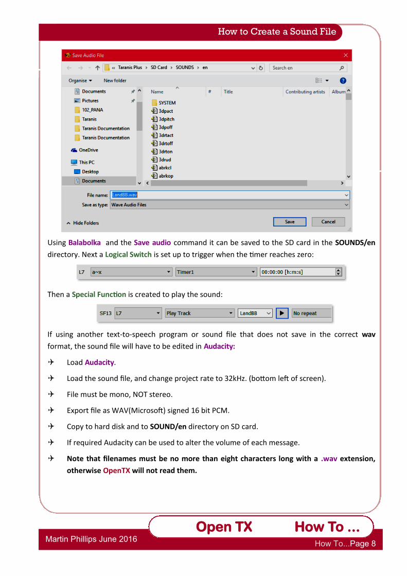
Using Balabolka and the Save audio command it can be saved to the SD card in the SOUNDS/en
directory. Next a Logical Switch is set up to trigger when the timer reaches zero:
Then a Special Function is created to play the sound:
If using another text-to-speech program or sound file that does not save in the correct wav
format, the sound file will have to be edited in Audacity:
Load Audacity.
Load the sound file, and change project rate to 32kHz. (bottom left of screen).
File must be mono, NOT stereo.
Export file as WAV(Microsoft) signed 16 bit PCM.
Copy to hard disk and to SOUND/en directory on SD card.
If required Audacity can be used to alter the volume of each message.
Note that filenames must be no more than eight characters long with a .wav extension,
otherwise OpenTX will not read them.
How to Create a Sound File
Op
Open TX Reference Section 4
2.1.7 How To
Martin Phillips June 2016 How To...Page 9
Open TX How To ...
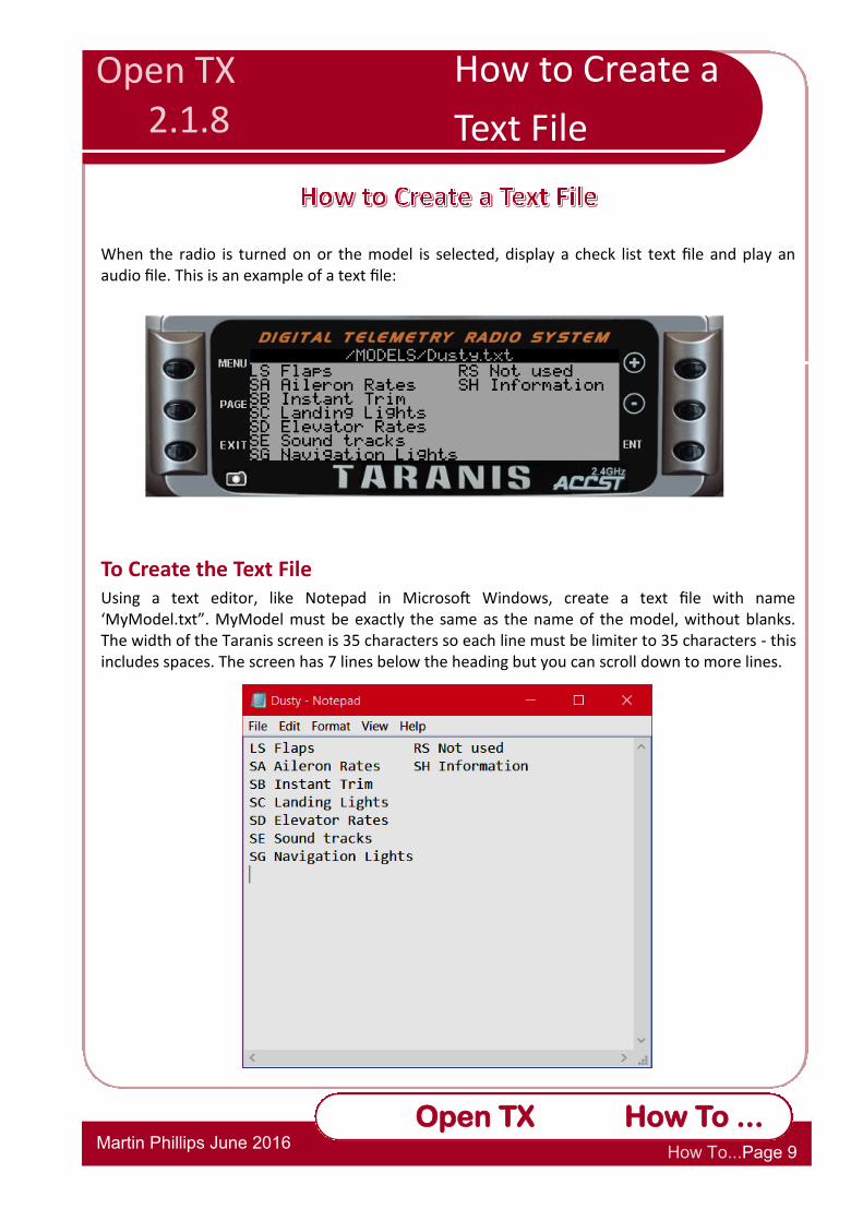
When the radio is turned on or the model is selected, display a check list text file and play an audio file. This is an example of a text file:
To Create the Text File Using a text editor, like Notepad in Microsoft Windows, create a text file with name ‘MyModel.txt”. MyModel must be exactly the same as the name of the model, without blanks. The width of the Taranis screen is 35 characters so each line must be limiter to 35 characters - this includes spaces. The screen has 7 lines below the heading but you can scroll down to more lines.
Open TX 2.1.8
How to Create a
Text File

Op
Open TX Reference Section 4
2.1.7 How To
Martin Phillips June 2016 How To...Page 10
Open TX How To ...
Information to include in the file:
Switch operation, e.g. flight modes, timer control
Slider operation, e.g. sound volume control
Pot operation
Telemetry data that is valid
Trainer setup
Pre-flight check list
Battery size
Reminders
Before the checklist will work, it must be enabled on the Model Editor Setup screen:
How to Create a Text File
Op
Open TX Reference Section 4
2.1.7 How To
Martin Phillips June 2016 How To...Page 11
Open TX How To ...
OpenTX has much flexibility for use with a buddy box system. The Taranis normally needs a
3.5mm mono jack lead to connect two transmitters together, however a stereo lead will work.
There are now some third party wireless modules available that fit in the module bay.
The basic buddy box concept is simple. There is a Master transmitter, which actually transmits to
the receiver, and a Slave transmitter where, if possible the RF signal is switched off. The Slave box
passes a copy of the output signal to the Master via the 2 core trainer cable. The Master sees these
inputs as Input Channels 1 – 16, if all are available on the Slave.
The inputs can be calibrated and scaled or multiplied. Each of the inputs is mapped to a joystick
and the mapping can include a weighting e.g. 125% and whether the signal is absolute (no master
input when the student is in control ) or additive where the master and the trainer signals are
added together and the resulting sum applied to the model. The second option sounds very clever
but having thought about it doesn’t really seem that useful.
The Taranis will buddy with other makes of transmitter too. Most Spektrums work although a few
will only work with a mono buddy lead. Buddying a Futaba to Taranis you will need a JR to Futaba
plug trainer lead.
Before Starting
Before you start you need to decide on some basic things:
If your Slave has dual rates will you use these with your student or will you use the dual rates
on the Master for both instructor and student?
You can configure the Master to take all of the flight control inputs from the buddy box or
just some of them. Initially control can be limited, with more control being added to the
program or via switches as the student progresses.
What control will you want to hand control across to the student? An obvious and simple
choice would be to use the spring loaded switch SH but you could use any of the other
physical or logical switches.
Open TX 2.1.8
How to Use the Trainer Function

Op
Open TX Reference Section 4
2.1.7 How To
Martin Phillips June 2016 How To...Page 12
Open TX How To ...
A Trainer System Using Two Taranis Transmitters.
Whether one uses just the two transmitters to set up the buddy system or presets some of the
functions first using the Companion does not matter.
1. Set up a new model on the Slave, taking note of the channel order, and setting the Trainer
Mode to slave.
How to Use the Trainer Function
Op
Open TX Reference Section 4
2.1.7 How To
Martin Phillips June 2016 How To...Page 13
Open TX How To ...
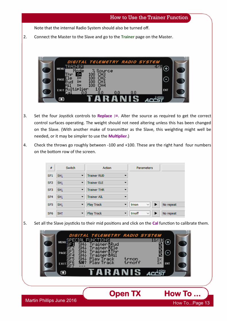
Note that the internal Radio System should also be turned off.
2. Connect the Master to the Slave and go to the Trainer page on the Master.
3. Set the four Joystick controls to Replace :=. Alter the source as required to get the correct
control surfaces operating. The weight should not need altering unless this has been changed
on the Slave. (With another make of transmitter as the Slave, this weighting might well be
needed, or it may be simpler to use the Multiplier.)
4. Check the throws go roughly between -100 and +100. These are the right hand four numbers
on the bottom row of the screen.
5. Set all the Slave joysticks to their mid positions and click on the Cal function to calibrate them.
How to Use the Trainer Function

Op
Open TX Reference Section 4
2.1.7 How To
Martin Phillips June 2016 How To...Page 14
Open TX How To ...
How to Use the Trainer Function
6. Decide on how control will be passed to the student. For this example switch H will be used
in the up position to give control of both joysticks to the student. Here also, voice
announcements are given.
Note, to disable any of the joysticks, simply unclick the
“enable” box on the right of the screen.
7. As always, check all the functions work as expected on
the model with it safely restrained, or the propeller
removed if it is electric.
Note: Other slave channels can be used with OpenTX if they are
available from the Slave transmitter. TR1 to TR16 are available
on both Inputs and Mixers. An extension of this could be to
have two pilots using two transmitters to control an elaborate
16 channel model, with, say, one pilot handling all the auxiliary

Op
Open TX Reference Section 4
2.1.7 How To
Martin Phillips June 2016 How To...Page 15
Open TX How To ...
How to Record Transmitter Settings
Once one has set up a few models on the transmitter, the switches and sliders used for each model
can get quite confusing. Ideally, keeping the same switches for the same functions is best, but this
is not always possible. This chart provides a simple paper method of keeping track of the
transmitter settings.
Open TX
2.1.8
How to Record
Transmitter Settings
Op
Open TX Reference Section 4
2.1.7 How To
Martin Phillips June 2016 How To...Page 16
Open TX How To ...
First, to understand how a flybarless (FLB) system works one needs to know how and what a flybar
does. A very simple explanation of a flybar function is to add stabilization to the rotor disc by
automatically changing the cyclic pitch angles of the rotor blades to help improve cyclic stability
and make cyclic control much more manageable. As the name suggests, FBL does away with the
flybar and with the help of electronic stabilization systems, "virtually" replaces the flybar (why
they are also called “virtual” or "electronic flybars").
The FBL helicopter is much easier to program using OpenTX because it does not require the
specialist helicopter functions of OpenTX. The following example is taken from a FBL helicopter, a
Blade 300X fitted with a Spektrum AR7200BX AS3X® (Artificial Stabilization - 3aXis) flybarless
system with built in receiver.
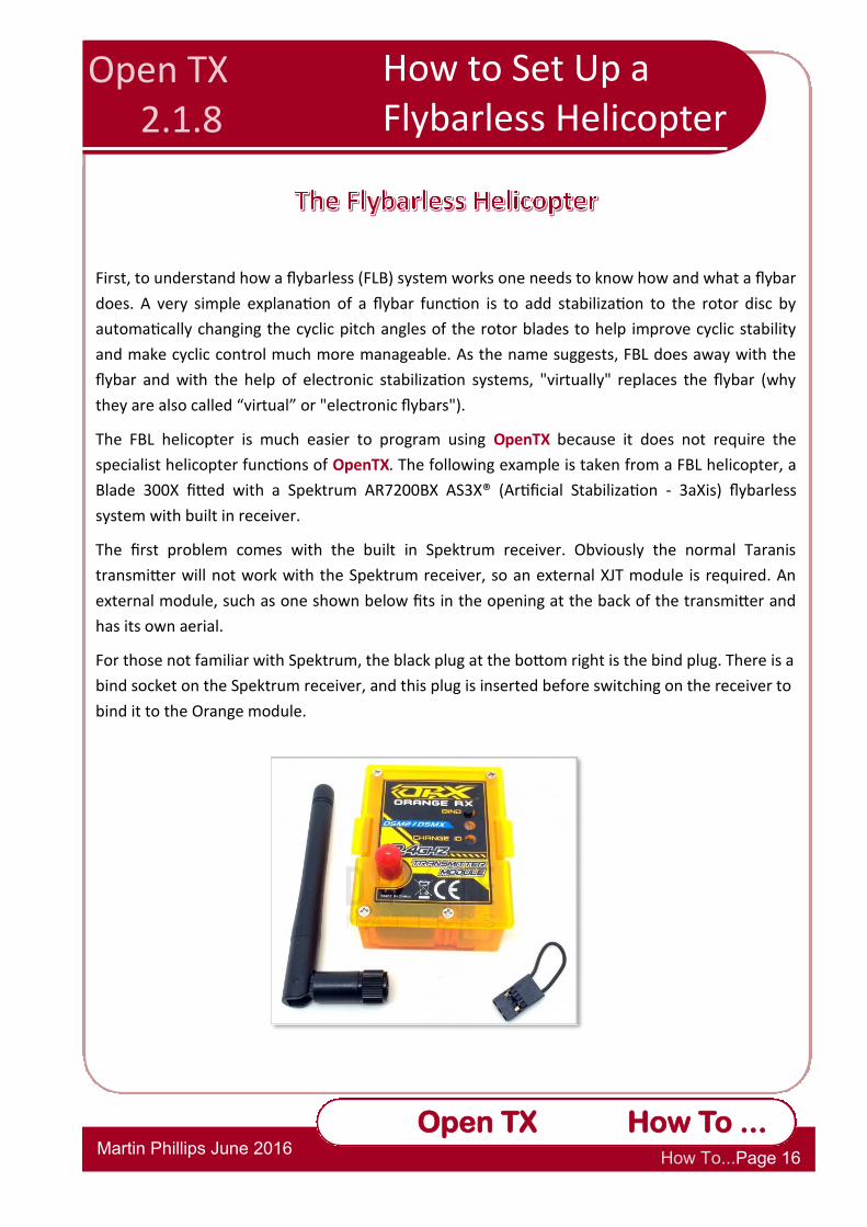
The first problem comes with the built in Spektrum receiver. Obviously the normal Taranis
transmitter will not work with the Spektrum receiver, so an external XJT module is required. An
external module, such as one shown below fits in the opening at the back of the transmitter and
has its own aerial.
For those not familiar with Spektrum, the black plug at the bottom right is the bind plug. There is a
bind socket on the Spektrum receiver, and this plug is inserted before switching on the receiver to
bind it to the Orange module.
How to Set Up a Helicopter Open TX 2.1.8
How to Set Up a Flybarless Helicopter
Op
Open TX Reference Section 4
2.1.7 How To
Martin Phillips June 2016 How To...Page 17
Open TX How To ...
How to Set up a Flybarless Helicopter
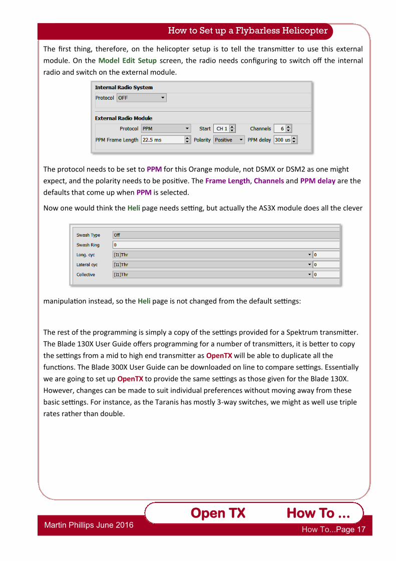
The first thing, therefore, on the helicopter setup is to tell the transmitter to use this external
module. On the Model Edit Setup screen, the radio needs configuring to switch off the internal
radio and switch on the external module.
The protocol needs to be set to PPM for this Orange module, not DSMX or DSM2 as one might
expect, and the polarity needs to be positive. The Frame Length, Channels and PPM delay are the
defaults that come up when PPM is selected.
Now one would think the Heli page needs setting, but actually the AS3X module does all the clever
manipulation instead, so the Heli page is not changed from the default settings:
The rest of the programming is simply a copy of the settings provided for a Spektrum transmitter.
The Blade 130X User Guide offers programming for a number of transmitters, it is better to copy
the settings from a mid to high end transmitter as OpenTX will be able to duplicate all the
functions. The Blade 300X User Guide can be downloaded on line to compare settings. Essentially
we are going to set up OpenTX to provide the same settings as those given for the Blade 130X.
However, changes can be made to suit individual preferences without moving away from these
basic settings. For instance, as the Taranis has mostly 3-way switches, we might as well use triple
rates rather than double.

Op
Open TX Reference Section 4
2.1.7 How To
Martin Phillips June 2016 How To...Page 18
Open TX How To ...
Blade 130X User Guide Settings
The transmitter is set to Mode 2.
The Blade User Guide for the Spektrum DX8 transmitter suggests:
1. Servo travel is 100. (Remember Spektrum servo travel is less than OpenTX. We will compensate for this later.)
2. There are no sub-trims set.
3. Elevator, rudder and pitch channels are reversed.
4. There are three flight modes, Normal, Stunt 1, and Stunt 2. No expo is set for any flight mode.
5. Dual rates are set at 100 for Normal mode, 85 for elevator, aileron and rudder in stunt modes 1 and 2.
6. Throttle and pitch curves are shown later, and there are no tail curves.
7. Timer is set to 4 minutes.
OpenTX Settings
Flight Mode: SE↑ Normal
SE- Idle-Up 1
SE↓ Idle-Up 2
Obviously the choice of switch is down to personal preferences.
Throttle cut: SF↑ Throttle cut enabled
SF↓ Throttle cut disabled Throttle joystick must be off before toggling the switch to enable the throttle.
Triple Rate: SD↑ High D/R
SD- Mid D/R
SD↓ Low D/R
Timer: Timer 1: Engine time. Count down starts once throttle opened and remains
above 25%.
Servos limit: Set to ±80% in order to match the Spektrum limits.
Curves: Curves are from the user guide.
Curve1 Normal throttle curve
Curve2 Idle-Up 1 throttle curve
Curve3 Idle-Up 2 throttle curve
Curve4 Normal pitch curve
Curve5 Idle-Up 1 & 2 pitch curve
How to Set up a Flybarless Helicopter

Op
Open TX Reference Section 4
2.1.7 How To
Martin Phillips June 2016 How To...Page 19
Open TX How To ...
1. Setting timers etc.
Timer 1 is set to count down from 4 minutes once the throttle is opened more than 25%.
2. The Flight Modes Screen
Three flight modes need setting, Normal, Idle-up 1 and Idle-up 2. Switch SE is used here. The Blade User Guide advises that no trims must be used as the AS3X receiver interprets those as signal inputs. These will need to be disabled in each of the Flight Modes screens.
One can alter the fade in times to suit personal preference.
How to Set up a Flybarless Helicopter

Op
Open TX Reference Section 4
2.1.7 How To
Martin Phillips June 2016 How To...Page 20
Open TX How To ...
3. The Inputs Screen
1. One must follow the Spektrum channel order, not, perhaps the one you normally use.
Spektrum is TAER. This does not have to be set on the General Edit Setup screen however.
2. The recommended Blade setup does not have expo, however this is down to personal
preference, and experimentation.
3. While these rates do not match the Blade User Guide, medium rates match the suggested
rates for Sport 1 and Sport 2. For normal mode, low rates provide a better setting for the
beginner. High rates matches the User Guide settings. Indeed, low rates could be changed
down to 50% for learning to hover.
4. While no expo is recommended in the Blade User Guide, this is very much down to personal
preference.
4. The Mixes Screen
The first three throttle settings are for the three flight modes. The last throttle setting links to a
logical switch, L2 to disable the throttle. Notice the Multiplex setting is set to Replace. This is very
important for the throttle cut to work correctly. Channel 5, the gyro, and channel 6, the pitch are
the standard channels for the Spektrum AS3X. Switch SC switches between heading hold and rate
mode for the gyro.
How to Set up a Flybarless Helicopter
Op
Open TX Reference Section 4
2.1.7 How To
Martin Phillips June 2016 How To...Page 21
Open TX How To ...
How to Set up a Flybarless Helicopter
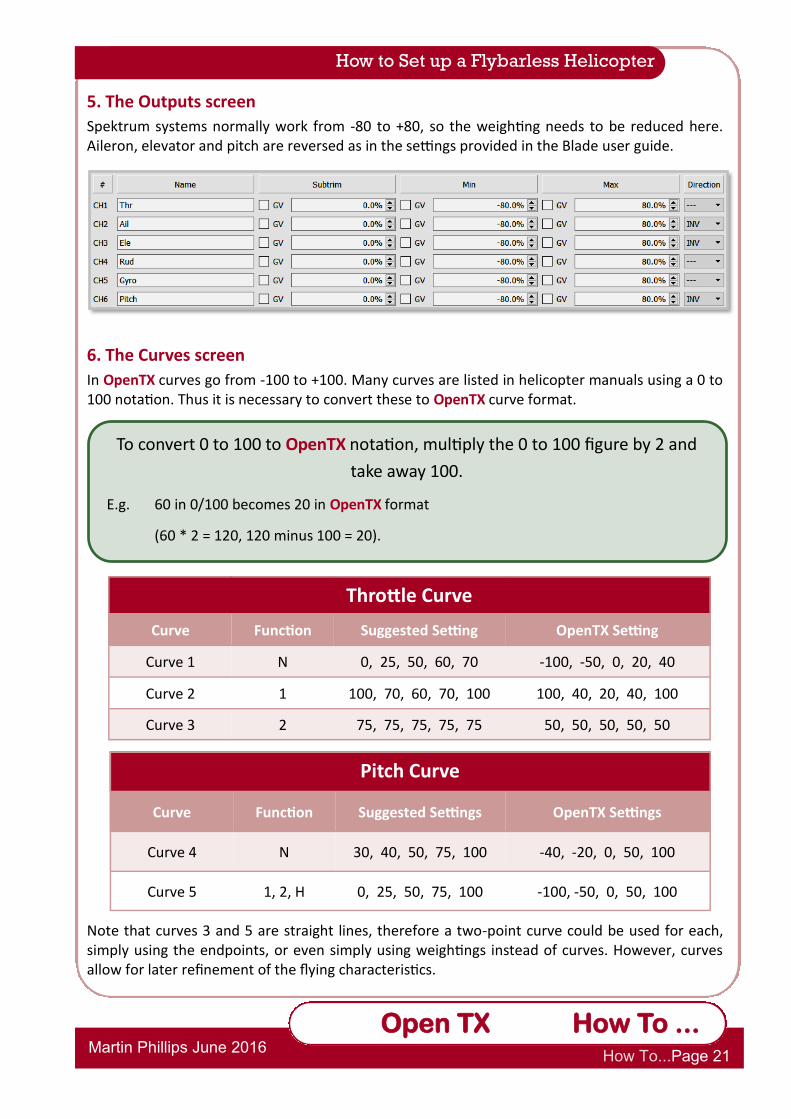
5. The Outputs screen
Spektrum systems normally work from -80 to +80, so the weighting needs to be reduced here. Aileron, elevator and pitch are reversed as in the settings provided in the Blade user guide.
6. The Curves screen
In OpenTX curves go from -100 to +100. Many curves are listed in helicopter manuals using a 0 to 100 notation. Thus it is necessary to convert these to OpenTX curve format.
Note that curves 3 and 5 are straight lines, therefore a two-point curve could be used for each, simply using the endpoints, or even simply using weightings instead of curves. However, curves allow for later refinement of the flying characteristics.
To convert 0 to 100 to OpenTX notation, multiply the 0 to 100 figure by 2 and
take away 100.
E.g. 60 in 0/100 becomes 20 in OpenTX format
(60 * 2 = 120, 120 minus 100 = 20).
Throttle Curve
Curve Function Suggested Setting OpenTX Setting
Curve 1 N 0, 25, 50, 60, 70 -100, -50, 0, 20, 40
Curve 2 1 100, 70, 60, 70, 100 100, 40, 20, 40, 100
Curve 3 2 75, 75, 75, 75, 75 50, 50, 50, 50, 50
Pitch Curve
Curve Function Suggested Settings OpenTX Settings
Curve 4 N 30, 40, 50, 75, 100 -40, -20, 0, 50, 100
Curve 5 1, 2, H 0, 25, 50, 75, 100 -100, -50, 0, 50, 100

Op
Open TX Reference Section 4
2.1.7 How To
Martin Phillips June 2016 How To...Page 22
Open TX How To ...
How to Set up a Flybarless Helicopter
7. Logical Switches and Special Functions
Having completed most of the basic setting up to match the Blade User Guide, logical switches
and special functions are used to provide a throttle cut and switch verbal feedback.
These logical switches provide a simple method of providing a throttle cut which cannot be
accidentally enabled when the throttle is not at a minimum.
SF1 puts a volume control on pot S2.
SF2 to SF4 give a voice alert for the three modes, though now sport 1 and sport 2 are called by
their more normal names, Idle Up 1 and Idle Up 2.
SF5 and SF6 give a voice alert for the motor arm/disarm.
SF7 to SF9 give a voice alert for the rates.
SF10 and SF11 give voice alerts for the gyro mode.
Finally, now the switches have been assigned, back on
the Setup screen the switch warnings can be set. It is
obviously very important to set SF, the motor disable
switch warning.
Op
Open TX Reference Section 4
2.1.7 How To
Martin Phillips June 2016 How To...Page 23
Open TX How To ...
This “How To” deals with setting up a CCPM electric helicopter. This example will be based on a 450 sized electric flybar helicopter with a 120° swash plate, and a mode 2 transmitter.
CCPM is an acronym that stands for Cyclic - Collective - Pitch - Mixing. This feature is only found on RC helicopters with collective pitch (as the name suggests), it doesn’t apply to fixed pitch helicopters. In the previous “How to”, the mixing for the three servos that control the collective were handled within the specialised gyro stabilized control system and combined receiver. This system handles all the clever mixing required to get the (usually) three servos linked to the swash plate to function correctly.
The complex collective cyclic pitch mixing for these three (or occasionally four) servos can also be handled by an appropriate transmitter. OpenTX offers excellent features to allow CCPM helicopters to be programmed, and thus a simple 6 channel receiver with a separate tail gyro can be utilised in the helicopter. The downside is that one needs to have a greater understanding of how such CCPM helicopters work, though maybe that is not really a downside, just a steeper learning curve. The positive side is, of course, the greater flexibility offered by OpenTX together with a better understanding of how that system works to be able to tune the helicopter more effectively.
The reader is advised to use this section in conjunction with Part 3 of the Reference Guide where the Heli page is covered in the Model Editor.
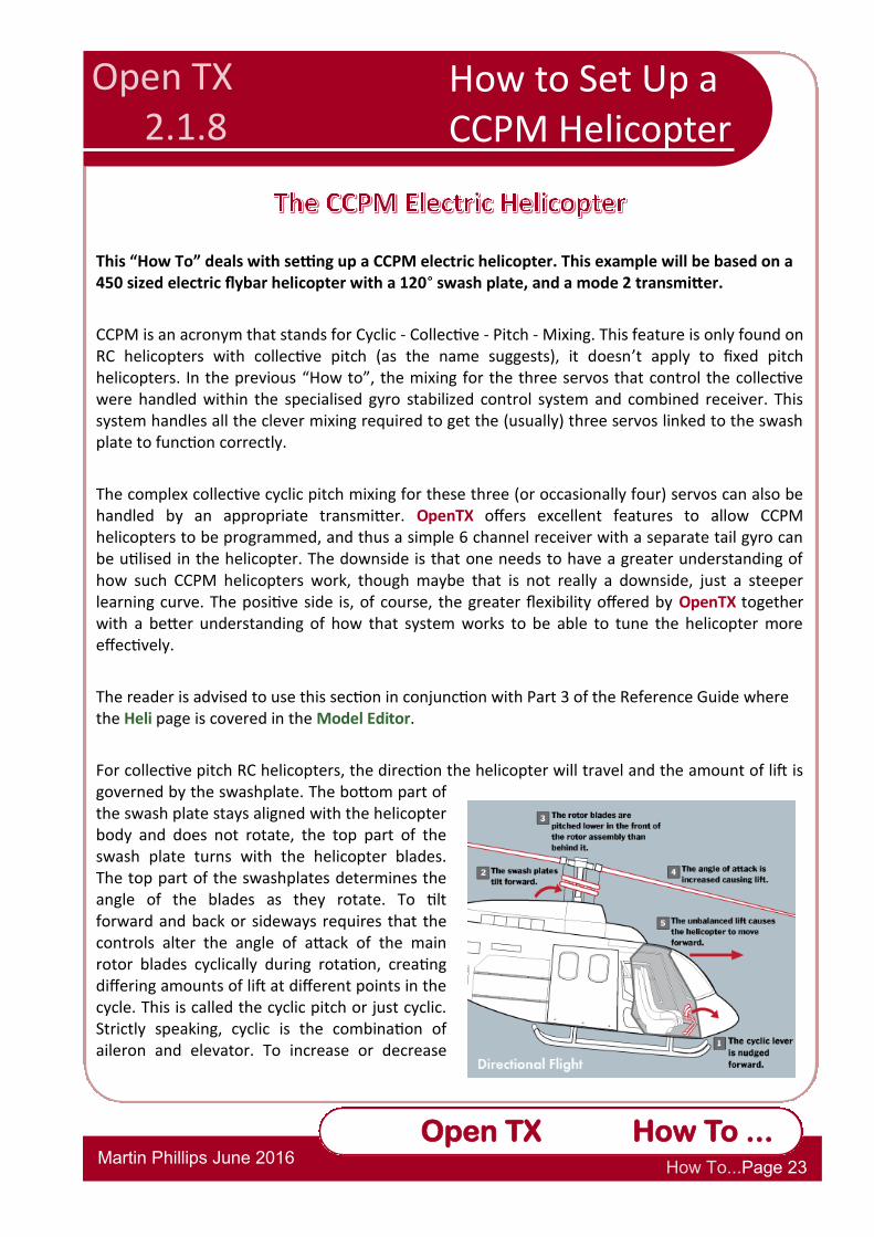
For collective pitch RC helicopters, the direction the helicopter will travel and the amount of lift is governed by the swashplate. The bottom part of the swash plate stays aligned with the helicopter body and does not rotate, the top part of the swash plate turns with the helicopter blades. The top part of the swashplates determines the angle of the blades as they rotate. To tilt forward and back or sideways requires that the controls alter the angle of attack of the main rotor blades cyclically during rotation, creating differing amounts of lift at different points in the cycle. This is called the cyclic pitch or just cyclic. Strictly speaking, cyclic is the combination of aileron and elevator. To increase or decrease
How to Set Up a Helicopter
Open TX 2.1.8
How to Set Up a CCPM Helicopter
Op
Open TX Reference Section 4
2.1.7 How To
Martin Phillips June 2016 How To...Page 24
Open TX How To ...
How to Set up a CCPM Helicopter
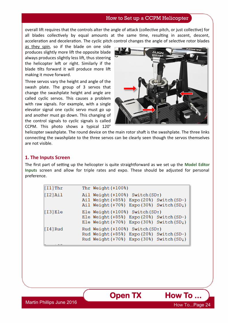
overall lift requires that the controls alter the angle of attack (collective pitch, or just collective) for all blades collectively by equal amounts at the same time, resulting in ascent, descent, acceleration and deceleration. The cyclic pitch control changes the angle of selective rotor blades as they spin, so if the blade on one side produces slightly more lift the opposite blade always produces slightly less lift, thus steering the helicopter left or right. Similarly if the blade tilts forward it will produce more lift making it move forward.
Three servos vary the height and angle of the swash plate. The group of 3 servos that change the swashplate height and angle are called cyclic servos. This causes a problem with raw signals. For example, with a single elevator signal one cyclic servo must go up and another must go down. This changing of the control signals to cyclic signals is called CCPM. This photo shows a typical 120° helicopter swashplate. The round device on the main rotor shaft is the swashplate. The three links connecting the swashplate to the three servos can be clearly seen though the servos themselves are not visible.
1. The Inputs Screen
The first part of setting up the helicopter is quite straightforward as we set up the Model Editor Inputs screen and allow for triple rates and expo. These should be adjusted for personal preference.
Op
Open TX Reference Section 4
2.1.7 How To
Martin Phillips June 2016 How To...Page 25
Open TX How To ...
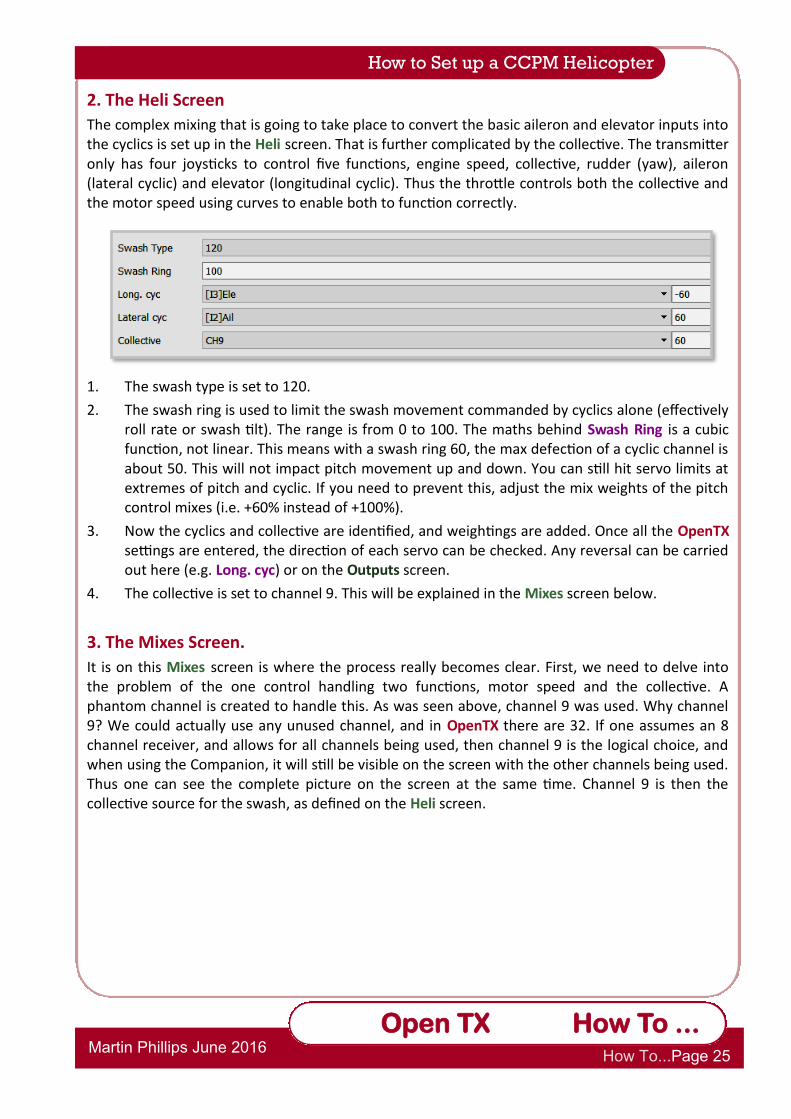
2. The Heli Screen
The complex mixing that is going to take place to convert the basic aileron and elevator inputs into the cyclics is set up in the Heli screen. That is further complicated by the collective. The transmitter only has four joysticks to control five functions, engine speed, collective, rudder (yaw), aileron (lateral cyclic) and elevator (longitudinal cyclic). Thus the throttle controls both the collective and the motor speed using curves to enable both to function correctly.
1. The swash type is set to 120.
2. The swash ring is used to limit the swash movement commanded by cyclics alone (effectively roll rate or swash tilt). The range is from 0 to 100. The maths behind Swash Ring is a cubic function, not linear. This means with a swash ring 60, the max defection of a cyclic channel is about 50. This will not impact pitch movement up and down. You can still hit servo limits at extremes of pitch and cyclic. If you need to prevent this, adjust the mix weights of the pitch control mixes (i.e. +60% instead of +100%).
3. Now the cyclics and collective are identified, and weightings are added. Once all the OpenTX settings are entered, the direction of each servo can be checked. Any reversal can be carried out here (e.g. Long. cyc) or on the Outputs screen.
4. The collective is set to channel 9. This will be explained in the Mixes screen below.
3. The Mixes Screen.
It is on this Mixes screen is where the process really becomes clear. First, we need to delve into the problem of the one control handling two functions, motor speed and the collective. A phantom channel is created to handle this. As was seen above, channel 9 was used. Why channel 9? We could actually use any unused channel, and in OpenTX there are 32. If one assumes an 8 channel receiver, and allows for all channels being used, then channel 9 is the logical choice, and when using the Companion, it will still be visible on the screen with the other channels being used. Thus one can see the complete picture on the screen at the same time. Channel 9 is then the collective source for the swash, as defined on the Heli screen.
How to Set up a CCPM Helicopter

Op
Open TX Reference Section 4
2.1.7 How To
Martin Phillips June 2016 How To...Page 26
Open TX How To ...
At first sight this looks complicated. There are three modes, switched using SE. There is normal mode, Idle 1 or sport flight, and idle 2 or 3D flight. Here, actual Flight Modes have not been programmed. On the throttle, each flight mode has a different curve. The weight is left at 100%. For the throttle, the weight is varied using the curves. Switch SF disables the motor, and the Multiplex is set to Replace (:=). Similarly channel 9 is programmed for the pitch. Each flight mode will also have its own associated pitch. Next, instead of assigning aileron, elevator and pitch to channel outputs 2, 3 and 4 which will control the three servos round the swash plate, assign CYC1, CYC2 and CYC3. OpenTX will do all the clever maths to ensure that each servo moves in the right proportions. What these do is mix aileron, elevator and pitch together and output signals for the servos on channels 2, 3 and 4. For 120° swash type, CYC1 is the servo in line with the helicopter from nose to tail.
Channel 6 controls the gyro function, either rate mode or heading hold. The handbook for the gyro will give appropriate weightings for this, though they will probably be in 1-100 format rather than the -100,to 100 OpenTX format.
How to Set up a CCPM Helicopter
Ensure CYC1 is the servo in line with the helicopter travel. CYC2 is CCW round from CYC1 and CYC3 is the matching pair to CYC3. If your swash points are the other way around (ie. CYC1 is South, not North), then reverse the aileron and elevator in the Heli-setup page. This way the pitch will still work correctly on the mix, just you have told the TX that the swash is backwards to the TX's expected swash orientation.

Op
Open TX Reference Section 4
2.1.7 How To
Martin Phillips June 2016 How To...Page 27
Open TX How To ...
4. The Curves Screen.
The starting point for the curves are the curve guidelines given in the helicopter handbook. Thus:
How to Set up a CCPM Helicopter
Throttle Curve
Curve Function Suggested Setting OpenTX Setting
Curve 1 N 0, 40, 60, 85, 100 -100, -20, 30, 70, 100
Curve 2 Idle 1 90, 85, 80, 85, 100 80, 70, 60, 70, 100
Curve 3 Idle 2 100, 80, 100 100, 60, 100
Op
Open TX Reference Section 4
2.1.7 How To
Martin Phillips June 2016 How To...Page 28
Open TX How To ...
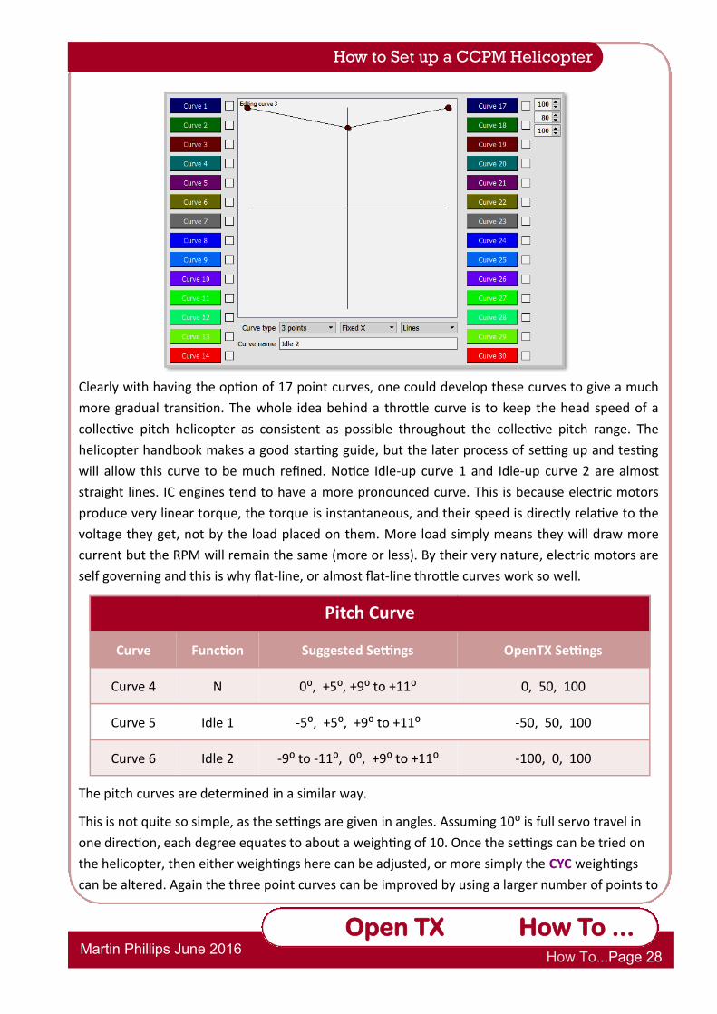
Clearly with having the option of 17 point curves, one could develop these curves to give a much
more gradual transition. The whole idea behind a throttle curve is to keep the head speed of a
collective pitch helicopter as consistent as possible throughout the collective pitch range. The
helicopter handbook makes a good starting guide, but the later process of setting up and testing
will allow this curve to be much refined. Notice Idle-up curve 1 and Idle-up curve 2 are almost
straight lines. IC engines tend to have a more pronounced curve. This is because electric motors
produce very linear torque, the torque is instantaneous, and their speed is directly relative to the
voltage they get, not by the load placed on them. More load simply means they will draw more
current but the RPM will remain the same (more or less). By their very nature, electric motors are
self governing and this is why flat-line, or almost flat-line throttle curves work so well.
The pitch curves are determined in a similar way.
This is not quite so simple, as the settings are given in angles. Assuming 10⁰ is full servo travel in
one direction, each degree equates to about a weighting of 10. Once the settings can be tried on
the helicopter, then either weightings here can be adjusted, or more simply the CYC weightings
can be altered. Again the three point curves can be improved by using a larger number of points to
How to Set up a CCPM Helicopter
Pitch Curve
Curve Function Suggested Settings OpenTX Settings
Curve 4 N 0⁰, +5⁰, +9⁰ to +11⁰ 0, 50, 100
Curve 5 Idle 1 -5⁰, +5⁰, +9⁰ to +11⁰ -50, 50, 100
Curve 6 Idle 2 -9⁰ to -11⁰, 0⁰, +9⁰ to +11⁰ -100, 0, 100

Op
Open TX Reference Section 4
2.1.7 How To
Martin Phillips June 2016 How To...Page 29
Open TX How To ...
How to Set up a CCPM Helicopter
Op
Open TX Reference Section 4
2.1.7 How To
Martin Phillips June 2016 How To...Page 30
Open TX How To ...
4. The Outputs Screen.
For now the Outputs screen is left blank. It may be needed once the actual helicopter is set up.
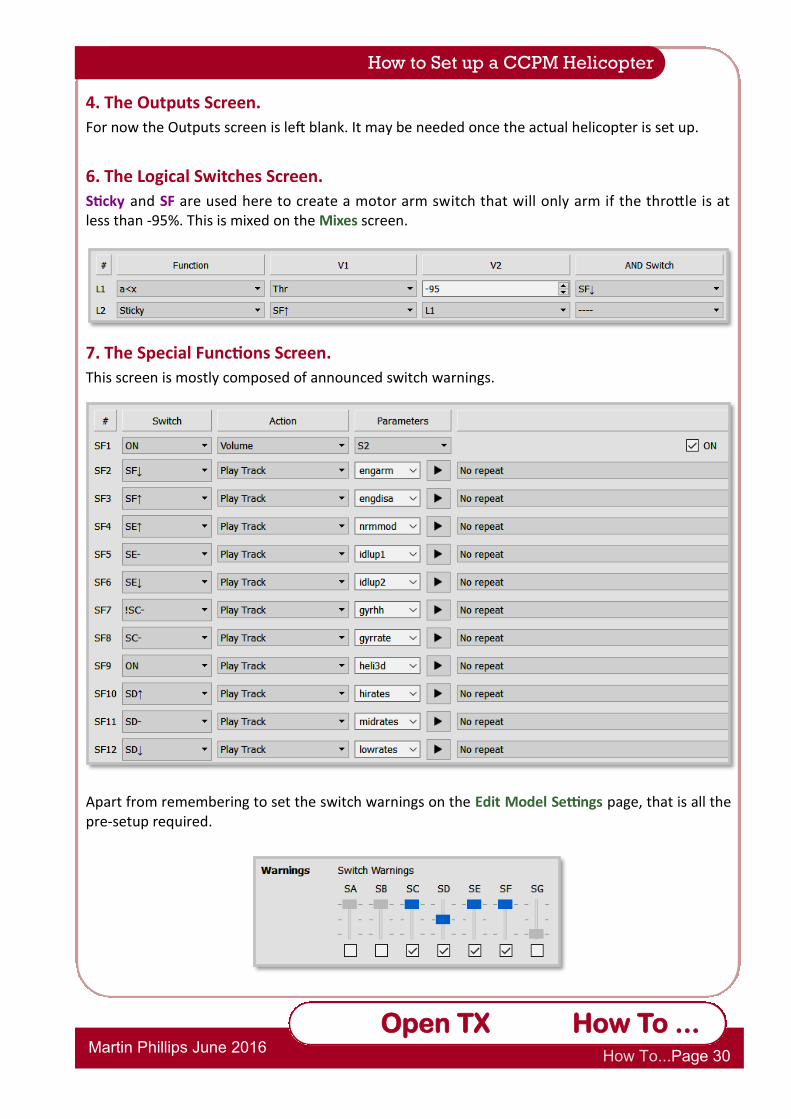
6. The Logical Switches Screen.
Sticky and SF are used here to create a motor arm switch that will only arm if the throttle is at less than -95%. This is mixed on the Mixes screen.
7. The Special Functions Screen.
This screen is mostly composed of announced switch warnings.
Apart from remembering to set the switch warnings on the Edit Model Settings page, that is all the pre-setup required.
How to Set up a CCPM Helicopter

Op
Open TX Reference Section 4
2.1.7 How To
Martin Phillips June 2016 How To...Page 31
Open TX How To ...
The following basic steps are to ensure CCPM works for the heli. The assumption is that the receiver is mounted on the heli and connected to the cyclic servos. The transmitter must be able to move the servos and you should be able to see the swash move. (i.e. receiver and servos must be powered on, servo horns attached and links to swash on).
1. Ensure the horns are near 90 degrees when at mid stick. (TH has linear pitch curve and you can use the monitor screen to ensure the transmitter is putting out 0 on Aileron, Elevator and Pitch channels). We can sub-trim them after mix correction is finished.
2. Next is "Find the odd one out". This is where you raise and lower the swash with pitch only and find which servo (if any) goes a different way. The servo that moves different to the others, invert/reverse in the servos screen. You will only need to reverse 1 servo. It does not matter if the swash goes up at lowest collective. This will be changed later if needed.
3. Ensure the elevator (nose-up/down) works the correct way. Centre the collective (swash middle) and pull back on the stick. If the front of the swash plate goes up good. If not, change the long. cyc. direction to INV in the swash menu on the Heli screen.
4. Now ensure the aileron (roll left/right) works the correct way. Centre the collective (swash middle) and roll to the right. If the swash tilts right good. If not, change the lateral cyc. direction to INV in the swash menu.
5. Next check the pitch. If up goes down, change the Coll. pitch direction to INV.
6. The swash ring setting on the screen is to ensure the servos are not sent beyond the limits and can be used to set a max swash tilt. This also has the effect of reducing the agility of the helicopter (as the swash cannot tilt as far).
7. Now that all the servos go in the correct direction you can use PPM centre on the 3 cyclic channels in the Servos screen to get the servo horns dead middle without limiting the end points. (Zero out cyc1, cyc2 and cyc3 temporarily to assist with this.)
8. Mechanically adjust the swash height to mid-travel by altering servo/swash pushrod lengths.
How to Set up a CCPM Helicopter
Cyclic 1
Channel 2
Cyclic 3
Channel 4
Cyclic 2
Channel 3
Nose

Op
Open TX Reference Section 4
2.1.7 How To
Martin Phillips June 2016 How To...Page 32
Open TX How To ...
How to Set up a CCPM Helicopter
9. Mechanically adjust the mid-collective pitch by altering swash/grip pushrod lengths.
10. Use the Servo page to adjust min and max servo values for cyclic servos to obtain desired min and max collective pitch (remove the zeroing out of cyc1, cyc2 and cyc3 first).
11. Test the cyclic pitch is as expected at min, mid and max collective pitch. Adjust by changing the collective weight and the cyclic weights.
12. Finally check the head speed to see if it is within the manufacturer’s suggested range. This can be done with a hand-held RPM sensor, but far more elegant is to use the FrSky RPM and temperature sensor, and then log the sensor during the first few flights. Remember, the aim is to keep the rotor speed as constant as possible in normal mode. The motor speed can be adjusted using the appropriate curve, developing it from the simple starting curve given earlier. If the speed is much too high or low to adjust using curves, then consider changing the gearing, or in extreme cases, using a battery with a higher or lower cell count.
13. On the subject of monitoring, the cell voltage and current consumption can also be monitored to check both current usage and to find the reasonable flying time.

Op
Open TX Reference Section 4
2.1.7 How To
Martin Phillips June 2016 How To...Page 33
Open TX How To ...
How to Set up a CCPM Helicopter How to Create a Kill Switch
Open TX 2.1.8
It is often useful to have a switch to disable the electric motor on a model. Simple disable switches are readily created, but are not foolproof. The aim here is to have a kill switch that is almost foolproof. The system starts off disabled, requires a switch (SE) to enable, and crucially cannot be accidently disabled whilst in flight. However, this last requirement does mean that an audible warning must to be used to notify whether the system is armed or not. Switch E in the mid position is used for the “on” state, and has to be moved to the SE↓ position for more than 2 seconds but less than 5. Similarly SE↓ is switched again for the same time to disarm. In both arm and disarm, the throttle has to be at -100.
The core of this kill switch is in the Logical Switches.
L1 tests that the throttle is off, and that switch E is not off. L3 provides the function to test that SE↓ has been moved for between 2 and 5 seconds, and L2 uses a sticky to switch between the “on” state and the “off” state. L2 is used as the control for the motor to be on or off.
This control is seen on the Mixes page where the throttle is set to minimum, and then replaced ( := ) with an active throttle when switch L2 becomes active.
Finally, audible warnings are set up in the Special Functions screen.
SF3 creates a bleep every second as a guide as to how long to hold the switch down. SF1 and SF2 are very necessary, as the motor will not disarm until the throttle is at a minimum and the switch sequence has been completed. The switch position cannot be relied on as a guide as to whether the motor is enabled. The physical switch E can be moved to any position but will have no effect without the other conditions being true. (The Amber voice pack is shown.)

Op
Open TX Reference Section 4
2.1.7 How To
Martin Phillips June 2016 How To...Page 34
Open TX How To ...
How to Create a Kill Switch
As an alternative, some might prefer to use the momentary switch, SH and toggle that for at least 2 seconds, but no more than 5. Personally I think this version is more elegant, however as a mode 2 flier I much prefer to have the throttle cut on the same side as the throttle, and secondly that single momentary action switch is very much in demand for other functions.
There is no change in the Mixes screen from the version show on the previous page:
Note:
Although a good idea to still do so, it is not necessary to have a switch warning for the kill switch.