OPEN SYSTEMS NETWORKING TCP/IP AND OSI · TCP/IP Has Strongly Influenced the Design of OSI Many of...
603
OPEN SYSTEMS NETWORKING TCP/IP AND OSI David M. Piscitello and A. Lyman Chapin Addison-Wesley Publishing Company Reading, Massachusetts Menlo Park, California New York Don Mills, Ontariao Wokingham, England Amsterdam Bonn Sydney Singapore Tokyo Madrid San Juan Paris Seoul Milan Mexico City Taipei
Transcript of OPEN SYSTEMS NETWORKING TCP/IP AND OSI · TCP/IP Has Strongly Influenced the Design of OSI Many of...
OPEN SYSTEMS NETWORKING
TCP/IP AND OSIDavid M. Piscitello and A. Lyman Chapin
Addison-Wesley Publishing Company
Reading, Massachusetts Menlo Park, California New YorkDon Mills, Ontariao Wokingham, England AmsterdamBonn Sydney Singapore Tokyo Madrid San Juan Paris Seoul Milan Mexico City Taipei

OPEN SYSTEMS NETWORKING

Addison-Wesley Professional Computing Series
Brian W. Kernighan, Consulting Editor
Ken Arnold/John Peyton, A C User’s Guide to ANSI C
Tom Cargill, C++ Programming Style
David A. Curry, UNIX® System Security: A Guide for Users and System Administrators
Scott Meyers, Effective C++: 50 Specific Ways to Improve Your Programs and Designs
Robert B. Murray, C++ Strategies and Tactics
Craig Partridge, Gigabit Networking
Radia Perlman, Interconnections: Bridges and Routers
David M. Piscitello/A. Lyman Chapin, Open Systems Networking: TCP/IP and OSI
Stephen A. Rago, UNIX® System V Network Programming
W. Richard Stevens, Advanced Programming in the UNIX® Environment
W. Richard Stevens, TCP/IP Illustrated, Volume 1

The publisher offers discounts on this book when ordered in quantity for specialsales. For more information please contact:
Corporate & Professional Publishing Group
Addison-Wesley Publishing Company
One Jacob Way
Reading, Massachusetts 01867
Library of Congress Cataloging-in-Publication DataPiscitello, David M.
Open systems networking : TCP/IP and OSI / David M. Piscitello and A.Lyman Chapin.
p. cm. - - (Addison-Wesley professional computing series)Includes bibliographical references and index.ISBN 0-201-56334-7 (alk. paper)1. OSI (Computer network standard) 2. TCP/IP (Computer network proto-
col) 3. Computer networks. I. Chapin, A. Lyman. II. Title. III. Series.TK5105.55.P57 1993004.6'2 - - dc20 93-17791
CIPCopyright © 1993 by Addison-Wesley Publishing Company
All rights reserved. No part of this publication may be reproduced, stored in aretrieval system, or transmitted, in any form, or by any means, electronic,mechanical, photocopying, recording, or otherwise, without the prior consent ofthe publisher. Printed in the United States of America. Published simultaneouslyin Canada.
Cover photo by Steven Hunt, The Image Bank
Text design by Carol Keller
ISBN 0-201-56334-7
Text printed on recycled and acid-free paper.
1 2 3 4 5 6 7 8 9 10 MU 96959493
First printing, August 1993
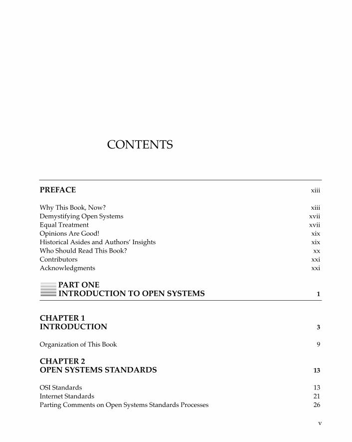
CONTENTS
v
PREFACE xiii
Why This Book, Now? xiiiDemystifying Open Systems xviiEqual Treatment xviiOpinions Are Good! xixHistorical Asides and Authors’ Insights xixWho Should Read This Book? xxContributors xxiAcknowledgments xxi
PART ONEINTRODUCTION TO OPEN SYSTEMS 1
CHAPTER 1INTRODUCTION 3
Organization of This Book 9
CHAPTER 2OPEN SYSTEMS STANDARDS 13
OSI Standards 13Internet Standards 21Parting Comments on Open Systems Standards Processes 26
PART TWOOPEN NETWORK ARCHITECTURES 31
CHAPTER 3CONCEPTS AND TERMINOLOGY OF OPEN SYSTEMS 33
Introduction 33Architectures 34Open Systems 35Architecture Wars 37Layers 37Terminology 45Entities 46Notation 47Services 47The Queue Model 50Connections and Connectionless 51What about Protocols? 54Protocol Headers and User Data 57Relating Service to Protocol 58Time-Sequence Diagrams 59A Final Fling with OSI Fundamentals 60Conclusion 61
CHAPTER 4THE LANGUAGES OF OPEN SYSTEMS 63
Introduction 63“Open” Languages—Breaking Language Barriers 64Data Representation 65Abstract Syntax Notation 68ASN.1 Data Types and Tags 69Modules 72Transfer Syntax—Basic Encoding Rules (BER) for ASN.1 73Do I Really Have to Deal with All This? 75Languages and the TCP/IP Community 76Conclusion 79
O P E N S Y S T E M S N E T W O R K I N G : T C P / I P A N D O S Ivi
C O N T E N T S vii
CHAPTER 5NAMES AND ADDRESSES 81
Names 82Addresses 88Registration Authorities 88Object Identifiers 96Conclusion 97
PART THREEUPPER LAYERS 99
CHAPTER 6OPEN SYSTEMS APPLICATIONS 101
Distributed Applications Services 106Conclusion 109
CHAPTER 7DIRECTORIES 111
The Telephony Model 112Directory System Principles 113Open System Directories 114The Domain Name System 115The OSI Directory 122The Directory Model 129The Relationship Between the OSI Directory and Message Handling Services 135The OSI Directory in the Internet 137Other Internet Directory Utilities 139Resource Location 141Conclusion 145
CHAPTER 8OPEN SYSTEMS MESSAGING: ELECTRONIC MAIL 147
OSI Message Handling System (X.400 MHS, MOTIS) 148
O P E N S Y S T E M S N E T W O R K I N G : T C P / I P A N D O S Iviii
Internet Mail 163Interworking between MHS and Internet Mail 172Conclusion 174
CHAPTER 9NETWORK MANAGEMENT 177
The Internet Approach: Keep It Simple 178OSI Common Management: Flexibility, At A Price 189Putting It All Together 205Where To from Here? 208Conclusion 211
CHAPTER 10“CORE” APPLICATION SERVICE ELEMENTS 213
Association-Control Service Element 214Reliable Transfer Service Element 223Remote Operations Service Element 232“Core ASE Wanna-bes” 243Conclusion 245
CHAPTER 11THE PRESENTATION AND SESSION LAYERS 247
Presentation Layer 247Session Layer 261Putting It All Together 281The Future of OSI Upper Layers 284Conclusion 285
PART FOURMIDDLE LAYERS 287
CHAPTER 12THE TRANSPORT LAYER 289
OSI’s Connection-oriented Transport Service 290
C O N T E N T S ix
TCP/IP’s Reliable Stream Service 291Interfaces to Transport Services 292Transport Addressing 300Five Classes of OSI Transport Protocol 301Conformance 309Comparing TP4 to TCP 310OSI Transport Connection Establishment 311Setting It All to UNIX 317Frozen References 320TCP Connection Establishment 320Normal Data Transfer in OSI Transport Protocol 325Reliability Mechanisms to Deal with the Real World 328Data Transfer in TCP—More of the Same 334Window Considerations for TP4 and TCP 337OSI’s Expedited Data 340TCP’s Urgent Data 341Timers and Open Transport Protocols 342Connection Release (Connection Refusal) in the OSI Transport Protocol 354Connection Release (Refusal) in TCP 356Datagram Transport Protocols—CLTP and UDP 358Conclusion 360
CHAPTER 13THE NETWORK LAYER 361
Architecture: The Internal Organization of the Network Layer 362Connection-oriented Network Service 372Connectionless Network Service 379Internetworking Protocols 383NL Protocol Identification in TCP/IP and Multiprotocol Environments 397Network Layer Addresses 398Conclusion 411
CHAPTER 14ROUTING 413
Source Routing and “Hop-by-Hop” Routing 414Routing Principles 415Routing Protocols 424Conclusion 465
O P E N S Y S T E M S N E T W O R K I N G : O S I & T C Px
CHAPTER 15DATA LINK AND PHYSICAL LAYERS 467
Taxonomy of Data Link Standards 468Point-to-Point Connection Standards 469Multiaccess Channel Standards 471Metropolitan Area Networks: FDDI and IEEE 802.6 DQDB 473Fast Packet Services and Technologies 482Very High Bandwidth as an Enabling Vehicle for OSI 500Conclusion 500
PART FIVETHE FUTURE OF OPEN SYSTEMS NETWORKING 503
CHAPTER 16MULTIPROTOCOL OPEN SYSTEMS 505
The Myth of “OSI Migration” 505OSI Is an Alternative, Not a Substitute 507OSI and TCP/IP Coexistence: Networking Détente 510Bringing OSI into a Network 520Are the Instrumentation and Expertise Available to Operate OSI Networks? 522Conclusion 522
CHAPTER 17AN ARCHITECTURAL ALTERNATIVE FOR THE INTERNET 525
What Is “the Internet”? 525A Naming-based Concept of Internet Connectivity 527
CHAPTER 18A READING FROM THE BOOK OF GENEBITS 533
APPENDIX ANETWORKING ACRONYMS 537
C O N T E N T S xi
APPENDIX BSOURCES 559
How and Where to Obtain Useful Information 559Information about TCP/IP and the Internet 560Information about OSI 564Authors’ Electronic Mail Addresses 566
REFERENCES 567
INDEX 587
PREFACE
Why This Book, Now?Open systems—in particular, Open Systems Interconnection (OSI) andTCP/IP1—are all the rage. There are plenty of books that discuss OSI andplenty more that discuss TCP/IP. However, despite the facts that thearchitecture and goals of OSI and TCP/IP are essentially the same, andthat they are really just currently popular manifestations of the same fun-damental principles and techniques, no previous book has examined thetwo in parallel. This book covers both Open Systems Interconnection andthe Internet architecture and protocols, commonly known as TCP/IP.There are many compelling reasons for examining these architectures inparallel, which is what this book intends to do.
TCP/IP Has Strongly Influenced the Design of OSI Many of the fea-tures and functions present in OSI trace their roots back to TCP/IP; forexample, OSI’s transport protocol class 4 and connectionless networkprotocol (CLNP) are functionally equivalent to TCP and IP. Furthermore,OSI’s application services—Message Handling System, File TransferAccess and Management, the Directory, and Virtual Terminal—are allattempts to improve upon their TCP/IP ancestors; the OSI MessageHandling System, for example, is intended to improve upon the highlysuccessful electronic-mail facilities provided in the TCP/IP protocol suiteby the Simple Mail Transfer Protocol by permitting facsimile, images, andvoice to accompany text in a mail envelope. The OSI Message Handling
xiii
1. Transmission control protocol (TCP) and internet protocol (IP) are the core protocolsof the Internet architecture.
O P E N S Y S T E M S N E T W O R K I N G : T C P / I P A N D O S Ixiv
System also provides a platform for Electronic Data Interchange and Of-fice Document Interchange, and the OSI Directory will provides a power-ful, object-oriented, global information base that can be accessed byhumans as well as by distributed applications such as electronic mail andnetwork file and resource management, building on services hithertoprovided by TCP/IP applications such as FINGER, WHOIS, and theDomain Name System.
OSI continues to profit from the experience accumulated duringmore than two decades of research on and real-world operation ofTCP/IP networks, recorded (since 1969) in an on-line document seriescalled the Internet requests for comments (RFCs). The RFCs constitute anarchive of networking experiences that are in many cases directly appli-cable to OSI protocol design and the deployment of OSI-based networksas well as to the TCP/IP world that has been their traditional focus. Thisis particularly true, for example, in the area of transport protocol opera-tion, in which OSI transport protocol class 4 and TCP share a commonparadigm of “reliability through retransmission.” OSI needs a researchplatform the likes of the Internet2 not only to test and draw interest to itsapplication services but to stress the limits of its routing and transportprotocols.
OSI Has Also Influenced TCP/IP TCP/IP’s open shortest path firstrouting protocol is derived from OSI’s intradomain intermediate systemto intermediate system routing protocol (which was itself an adaptationof a link-state routing protocol developed for IP under the auspices of theDefense Advanced Research Projects Agency). OSI’s data-definition lang-uage, Abstract Syntax Notation One, is used to define the Simple Net-work Management Protocol and its management information base. AndOSI’s Message Handling System and Directory are so promising thatthey are already operated over TCP/IP in large portions of the Internet.
OSI and TCP/IP Are Learning to Cooperate Government open systemsinterconnection profiles (GOSIPs) and other computer and communica-tion system procurement specifications mandate that OSI be introducedinto the networking environments of government (particularly defense)agencies in Europe and the United States. Mandates such as these, al-
2. The term Internet, with the initial I capitalized, refers to the worldwide interconnec-tion of a vast number of backbone, regional, and local (enterprise) networks that operateTCP/IP, OSI, and other protocols. The Internet is a constantly growing entity, andalthough it is difficult to determine its exact size, well over 1.5 million hosts are (at the timeof this writing) directly connected to the Internet using TCP/IP. A small, but growing,number of these hosts also use OSI protocols to connect to the Internet.
P R E F A C E xv
though highly criticized, have at least had the positive effect of causingdevelopers on both “sides” to work together. Although the relationshipbetween TCP/IP and OSI developers has ranged from quietly acrimo-nious to openly hostile in the past, the cold war is over (although, somehighly vocal pockets of resistance remain), a period of détente is ending,and a glasnost has begun, as both sides see the benefits of workingtogether. The number of “tweeners”—networking professionals whowork on standards and development in both the OSI and the TCP/IParenas—is growing, not because they think that it is important to coverall the political bases or because their positive self-image is enhanced bythe broad-mindedness implicit in such an arrangement, but because theessential technical and organizational problems of networking (particu-larly internetworking) are the same everywhere and do not divide cleanlyalong party lines. The increased cooperation in areas of mutual con-cern—including interdomain (policy-based) routing protocols, OSI inte-gration, and perhaps accredited standardization and government profil-ing of TCP/IP—will play an important role in the future of open systemsnetworking.
The History of OSI Is Significant—Yet Largely Unknown Havingread several books about OSI prior to undertaking this project, theauthors discovered that without the context of “having been there” toexplain some of the seemingly irrational behavior of the OSI standardsmakers—and to translate the often impenetrable “standardese” of OSI—existing books either leave a false impression of OSI or fail to leave anyimpression at all, since they merely coalesce, condense, and regurgitatethe OSI standards without separating what is important from what is not.The authors believe that one has a much better chance of understandinghow something works if one knows how it got to be that way, if someonepoints out the issues that have been overblown, and if the unlikely sce-narios are distinguished from the scenarios that are probable in real-world networks. The authors and contributors were present during themost significant periods of OSI standards development and remain activeas architects of a future, multiprotocol Internet. They are in a much betterposition to sort the standards wheat from chaff than those who firstencountered the issues only after the standards were published.
As Is the History of TCP/IP To a large extent, the history of TCP/IP isthe history of OSI. Those who are often perceived by the Internet com-munity to be the “rational core” of OSI standards developers were, forthe most part, weaned on TCP/IP: to the astonishment of some hard-core Internetters, they actually knew how to use and implement TCP/IP
O P E N S Y S T E M S N E T W O R K I N G : T C P / I P A N D O S Ixvi
and its applications before they became involved in the development ofOSI, but most important, they respected TCP/IP and appreciated theadvantages of continued cross-fertilization between OSI and TCP/IPtechnology.
A Multiprotocol Global Internet Is Coming! Open systems network-ing is the basis for the evolution of a truly global Internet. The signifi-cance of open systems networking cannot be understood by focusingattention on OSI or TCP/IP—or any “open” protocol architecture—in iso-lation. Only by examining both (eventually, all) of them in context canthe history and likely future of internetworking be understood.
From these observations come the objectives of this book: make OSIintelligible, relate it to TCP/IP, and in the process, reveal the stories—thewhys and wherefores—behind the standards. These objectives serve asthe major differentiator between this and many other books that appearto cover some of the same material. Open Systems Networking: TCP/IP andOSI is not simply a reiteration or regurgitation of the OSI and TCP/IPstandards, nor does it treat open systems networking as an adjunct to abook whose main purpose is to talk about data communications. Suchreference material already exists and is not sufficient.
Several OSI-related books are specialized. Rather than examine OSI ina detailed manner from top to bottom (more often, bottom to top), theyfocus on a specific area of OSI: upper layers, lower layers, perhaps a par-ticular OSI application such as the Message Handling System or theDirectory. These are valuable but often can’t serve as (nor do they pretendto be) a comprehensive primer. Open Systems Networking: TCP/IP and OSIattempts to present OSI and TCP/IP in a methodical, stepwise progres-sion, beginning with basic architectural principles, the application of thoseprinciples to specific services and protocols, and the behavior of computersystems that operate the protocols and form open networks.
Open Systems Networking: TCP/IP and OSI further departs from thenorm by adopting a “top-down,” user-oriented approach. Electronicmail, for example, is discussed in the following contexts: What does itdo? What does a network have to do to make it happen? How do thesefunctions appear in OSI and TCP/IP (and why do they appear in thatparticular way)? A consequence of applying the “top-down” approach isthat the text makes forward references (typically, toward more detailedexplanations of what has been described at a conceptual level); a benefitis that readers deal first with aspects of open systems networking at aconceptual level (what something is) and later with the specific details ofhow something actually works.
P R E F A C E xvii
Demystifying Open SystemsOSI and TCP/IP share concepts, even some culture, but they certainly donot share terminology! OSI and TCP/IP both suffer from “acrony-mania”;3 OSI, in particular, is far and away the most acronymaniacaltechnology yet inflicted on the world of networking. This book attemptsto translate OSI (and TCP/IP) architecture and terminology from “ISO-ese” to “plain-speak.” A major objective of Open Systems Networking:TCP/IP and OSI is to make it easier for readers to understand and applybasic networking concepts in the context of open systems. To someextent, the use of acronyms is unavoidable (as readers may already havenoted). In this book, the use of acronyms is as much as possible aban-doned in favor of more popular and accessible terminology; for example,the word packet or frame is preferred to the less intuitive OSI acronymPDU (which stands for “protocol data unit”).
Equal TreatmentOpen Systems Networking: TCP/IP and OSI compares and contrasts theOSI approach with the TCP/IP approach in what is intended to be anevenhanded and pragmatic fashion, taking sides on technical issueswhen appropriate but avoiding the political-party fervor with which thecomparison is often fraught. For example, if the question “What doesOSI’s MHS add to message handling that TCP/IP’s SMTP lacks?” isinterpreted as biased in favor of OSI, the balance is eventually restoredwhen the question “Why has SNMP, not CMIP, been so widely em-braced by the industry?” is also posed and answered.
In some areas, the book may appear to be almost chaotically neu-tral, suggesting, for example, that TCP/IP’s Simple Network Manage-ment Protocol might be used over OSI’s connectionless transport proto-col to manage OSI network resources or that the OSI Directory be usedover TCP/IP to provide an array of information services. Although thismight be interpreted as heresy (or at least disloyalty) by purists in theOSI and TCP/IP communities, the authors believe that it serves the usercommunity much better than orthodoxy, since it demonstrates that open
3. Acronymania \ 'ak-r -'nim-'ma-ne- , -ny \ n. [orig. Piscitello, D. 1991] madness over
acronyms; also rage or eager desire for anything related to acronyms; insane or morbidcraving for words formed from the initial letters of other words; mental disorder character-ized by high, uncontrolled excitement over the creation of an endless stream of wordsformed from the initial letters of other words (Decidedly not Webster’s . . .).
e ee
O P E N S Y S T E M S N E T W O R K I N G : T C P / I P A N D O S Ixviii
systems networking is about solving communications problems, not cre-ating or complicating them.
Notwithstanding the goal of equal treatment, readers will findmuch more information in this book about OSI than about TCP/IP, fortwo reasons. The first is the extent to which the OSI architecture—thefamous seven-layer model—has been adopted, even by its critics, as away to talk about open systems networking, even when the subject is notOSI. The concepts and terminology introduced by the OSI referencemodel have in many cases become the standard lingua franca of networkarchitecture, to such an extent that even a completely evenhanded treat-ment of OSI and another protocol suite is liable to sound like a treatise onOSI, with the other suite appearing to be short-shrifted. The authorsknow of no way, short of introducing yet a third “neutral” nomenclature,to avoid this and consequently have not tried to do so.
The second is the sheer volume of information that a truly completepresentation of the entirety of OSI and TCP/IP would represent, whichcould not possibly be contained within a single book such as this. Inthose cases in which it is simply not feasible to provide truly equal treat-ment to both the OSI and the TCP/IP variations of the same theme, theauthors have elected to describe the OSI side in detail and to compareand contrast the corresponding TCP/IP component with the moredetailed OSI description. This choice recognizes that a number of high-quality books describing TCP/IP are already widely available,4 and thatthe technical specifications of the components of TCP/IP are not onlyavailable electronically on the Internet (at no cost beyond the network-access cost of retrieving them from one of the Internet document ar-chives), but they are much easier to read and understand than their OSIcounterparts. To successfully plow through the piles of OSI specifications(which must be purchased, at significant cost, from national standardsorganizations such as the American National Standards Institute withoutlosing one’s way simply requires more experienced guidance . . . andmoney! The authors can, at least, provide the former.
4. Readers are encouraged to refer especially to Comer (1991), Stevens (1990), andPerlman (1992a).
P R E F A C E xix
Opinions Are Good!The “value-neutral” approach adopted in many recent textbook-styletreatments of OSI presents readers with the equivalent of an undifferen-tiated memory dump; by failing to distinguish between what is impor-tant and what isn’t, these books serve the objective purpose of presentingthe facts about OSI but make it very difficult for readers to understand it.A description of how each of the five OSI transport protocol classesworks is a fine thing, but without knowing why there are five classes(why not just one? if more than one, why five?), and without being toldthat only two of the classes are ever used in practice, readers are not likelyto come away with a very useful understanding of OSI transport ser-vices. The authors of Open Systems Networking: TCP/IP and OSI are in aposition to make informed value judgments and to present the informa-tion in a format that leads to understanding rather than suffocation: likehaving an intelligent debugger, if you will, rather than a core dump.
Historical Asides and Authors’ InsightsThe historical and anecdotal observations made throughout the text arebased on direct participation by the authors in the OSI and TCP/IP stan-dards processes for the past 15 years, including participation in theInternet Engineering Task Force (IETF), the Internet EngineeringSteering Group (IESG), and the Internet Architecture Board (IAB), aswell as in many of the national and international standards committees.Many of the historical observations (“asides”) concentrate on the stan-dards process or the results of that process; by convention, they are itali-cized and proceeded in the text by the symbol .
Readers familiar with The Open Book, by Dr. Marshall T. Rose,should not confuse these historical asides with the “soapboxes” used inMarshall’s book. The Open Book is enlivened considerably by the use ofsoapboxes on which Marshall perches deliberately provocative, “notstrictly objective” commentary on the material contained in the maintext. Much of this commentary expresses Marshall’s righteous indigna-tion at the follies and pedantry of OSI and the OSI standardizationprocess, claiming that since he wasn’t there, he doesn’t understand whatreally happened, but just look at the result! The net effect, of course, is tocreate and promote a pervasive negative impression about everythingthat carries the “OSI” label. (Some people, of course, believe that Mar-
✧AHA✧
O P E N S Y S T E M S N E T W O R K I N G : T C P / I P A N D O S Ixx
shall’s negative impression of OSI is richly deserved . . .)The purpose of the historical asides in Open Systems Networking:
TCP/IP and OSI is not to use “pen up” observations to take sides in a con-test between OSI and TCP/IP. The historical asides and authors’ insightsin this book do not rush to defend the OSI standards or the OSI stan-dards-making process; in fact, they are often indictments of bad decisionsthat led to bad standards, since they reveal how the decisions were made,exposing the inherent flaws in applying a committee consensus processto the development of technology. (In some cases, of course, the authorsthemselves are wholly or partly to blame, since they were there and mighthave known better; those asides can be read as rueful self-criticism.) Theasides and insights are also used to sort the good in OSI from the bad;often, criticism is accompanied by a recommended action—such as“Ignore this part of standard X,” or “Implement only these functions ofstandard Y”—or a forecast of what will really matter in the future. It isworth noting that the asides and insights are not confined to OSI; theshortcomings and missteps of the “working code and rough consensus”process applied in the Internet community bring TCP/IP under fire aswell. The authors have jostled the memories of several of the originalDARPA researchers to add an historical perspective of TCP/IP as well.
Who Should Read This Book?For networking neophytes, this book may serve as both a primer and aroad map; it answers questions such as “How does it work?,” “What isrelevant and what is not?,” and perhaps most important, “Why did theychoose to do it this way?” For experienced networking professionals,especially those familiar with TCP/IP, this book demystifies OSI and inthe process illustrates both its strengths and its weaknesses. For thoseinvolved in network planning and administration, especially in environ-ments in which TCP/IP and OSI coexistence, transition, and migrationare the buzzwords du jour, this book provides a basis for understandingnot only how OSI and TCP/IP work but how they might peacefully andproductively coexist in complex, multiprotocol internets, today andtomorrow.
Open Systems Networking: TCP/IP and OSI does not give an exhaus-tive explanation of the details of every protocol or service. The goal ofthis book is not to serve as the definitive “reader’s companion” for everyopen systems networking standard but to present and answer the “why”and “how” questions of building open networks. The book therefore
P R E F A C E xxi
includes only as much protocol detail as is necessary to facilitate under-standing; no one should expect to use it as a protocol implementationmanual. However, the book should enable the system designer to under-stand the way in which OSI and TCP/IP systems work and the way inwhich a specific set of concepts and terminology is used to define theprotocols. It should also assist anyone who has a fundamental under-standing of data communications and networking to understand andapply the principles and protocols of OSI and TCP/IP to satisfy real-world computer-networking requirements.
ContributorsThe authors are indebted to Lisa Phifer, Deirdre Kostick, Paul Francis(née Tsuchiya), and Yakov Rekhter, who made substantial contributionsto the chapters on network management and routing. Lisa also con-tributed to both the text and the historical insights provided in the chap-ters on the OSI upper layers and the application service elements. It is noexaggeration to say that her timely and diligent review greatly improvedthe quality of this book.
AcknowledgmentsNo project of this magnitude can succeed without the assistance offriends and family. Radia Perlman deserves credit for insisting that wewrite this book and then alternately encouraging and chiding us untilwe had. Among our friends in the Internet community, we wish tothank Stephen Crocker, Jon Postel, and Vinton Cerf for their technicalassistance and the contribution of anecdotal information on TCP/IP.Among the “tweeners,” our thanks go to Ross Callon, John Burruss,Christine Hemrick, Kaj Tesink, Nancy Hall, Rob Hagens, Steve Kille,Susan Hares, Mark Knopper, Hans-Werner Braun, Erik Huizer, andDavid Katz. We also wish to acknowledge our colleagues (past and pres-ent)—Jeff Rosenberg, Jim Hopkins, Gary Summers, Scott Stein, TracyCox, Larry Lang, Phil Karn, Ted Brunner, Kathy So, James Davin, DaveOran, Chuck Wade, John Day, Bud Emmons, and Al Grimstad—whothroughout our careers offered daily challenges and valuable insights,and enthusiastically supported our efforts. John Burruss, Radia Perlman,and Phil Almquist in particular deserve mention for having provided
O P E N S Y S T E M S N E T W O R K I N G : T C P / I P A N D O S Ixxii
excellent technical reviews of the original manuscript. We would certainly be remiss if we did not mention both the OSI
and Internet communities as well; for more than 15 years, they have pro-vided an immensely fertile testing ground for the formulation of network-ing ideas, and although the road has been somewhat rocky, we feel privi-leged to be a part of the process of developing networking technology.
Our wives and children demonstrated enormous patience and un-derstanding, and offered support and encouragement that was simplyremarkable. It will be difficult to repay the lost weekends and evenings,but a public acknowledgment of how much we love and appreciate themseems like a good start.
Finally, we’d like to thank Mark Taranto, who pounded the Byz-antine principles of real analysis and metric space into Dave’s head; hemay not have contributed specifically to this project, but it’s a good betthat Dave wouldn’t be writing a book with Lyman without having com-pleted his undergraduate degree in mathematics.

PA R T O N E
INTRODUCTION TO OPEN SYSTEMS
1 INTRODUCTION
Books that discuss computer communications invariably begin by draw-ing analogies between computer networking and earlier, landmarkinventions that have had a profound impact upon, perhaps even “revo-lutionized,” society. Andrew S. Tanenbaum compares the impact of com-puter networks to the mechanical systems accompanying the IndustrialRevolution, while Douglas E. Comer likens digital communications net-works to the great railroads of the nineteenth century. But neither theIndustrial Revolution nor the railroad has made as great an impact onhuman civilization as “the marriage of the engineering of telecommuni-cations to that of the computer industry” (Martin 1976, 2). Why? No pre-vious technology has advanced quite so rapidly and with such unboundedhorizons as the computer, and no previous technology has achieved any-thing close to the ubiquity of the modern telecommunications system.
James Martin accurately predicted that through this union, thetelecommunications system would aid distributed processing, and thecomputer would facilitate telephony switching. The actual chronology ofevents in fact exceeded Martin’s expectations, for shortly after his specu-lation in the mid-1970s, information processing was delivered to thedesktop. A decade marked by increased computer speed, memory, andstorage, accompanied by a proliferation of useful and distributed appli-cations, has fundamentally changed the way in which much of societyworks and interacts: we now send mail, do our banking, and exchangedocuments electronically, from our business places and our homes. Thischange in human behavior has affected the telecommunications systemmore profoundly than Martin forecast when he suggested that comput-ers would merely facilitate switching. It adds a level of sophistication to
3
O P E N S Y S T E M S N E T W O R K I N G : T C P / I P A N D O S I4
the equipment attached to the telephone network that could never havebeen achieved by a telephone handset with a 12-digit keypad. In additionto placing a voice call to conduct business, we increasingly seek toexchange images—files of immense size—and to animate them in theprocess, and we expect do so in milliseconds. In many respects, informa-tion has become as important a commodity to switch as voice. The tradi-tional voice and data networks will undergo profound changes in thenext decade, as both seek to integrate the services of the other.
Therein lies a problem with the marriage. As in the Houses ofMontague and Capulet, the parents of voice and data don’t get along.Rarely have computer and communications providers shared a commonset of beliefs and purposes. In the House of Telephony, data switching hashistorically been viewed as a second-tier service, incapable of ever achiev-ing the “cash-cow” status of voice, and therefore much less important tothe “bottom line.” In the House of Data, telephony providers have beencriticized as being intolerably slow to respond to the increasing demandfor bandwidth, willing only to focus on “dataphony,”1 and the data ser-vices offered by “common carriers” have historically been much less pow-erful and flexible than on-premises, local area networking alternatives.
Never have these differences of culture and philosophy been moreobvious than during the development of Open Systems Interconnection,during which the debates between the Houses of Voice and Data wereoften more religious and political than technical.2 This is perhaps be-cause, by the mid-1970s, the networking of computers had begun to looklike a lucrative new market opportunity rather than an amusing academ-ic toy. The notion of open systems networking became interesting to boththe voice and the data worlds at nearly the same time, for profit’s sakeand no other; and both the House of Data and the House of Voice wantedto secure as big a slice of the new pie as possible.
But what exactly is “open systems networking”? There are, ofcourse, many ways to answer this question. The answer certainly doesnot lie strictly within the reference model for Open Systems Interconnec-tion (ISO 7498, 1984), because architectures and protocols other than OSI
1. Dataphony is a term coined by Christine Hemrick, presently with Cisco Systems, todistinguish low-bandwidth, terminal-to-mainframe networking applications from high-bandwidth, distributed-processing applications—i.e., real data networking.2. OSI wasn’t the first pretext for these debates. The initial experience of the conflict forone of the authors can be traced back to the first time a Bell Telephone employee markedthe area surrounding a data access arrangement in a computer laboratory at a Burroughsdevelopment facility with red tape, plopped down a Bell modem and telephone, and said“Don’t touch!” Shortly thereafter, it was necessary to move the entire wall without disturb-ing the tape.
I N T R O D U C T I O N 5
are widely acknowledged as bases for open systems networking. Thepublication of the OSI reference model is noteworthy primarily becauseit represents an internationally recognized effort at codifying what con-stitutes “openness.” What is recorded in the OSI reference model as thedefinition of an open system is in fact far less significant than the eventsthat motivated—in the minds of some, provoked—an international inter-est in open systems networking.
Even at this late stage in the evolution of open systems networking,any attempt at defining open systems is highly subjective. For the purposesof this book, however, open systems networking implies or suggests thefollowing: multivendor, interoperable hardware and software systems,based on internationally recognized and publicly available documenta-tion (“standards”), which can be acquired “off the shelf” (as a standardrather than special-order product).
Why is everyone so excited about open systems? Some are excitedbecause the concept represents “safe networking”: protection from pro-prietary networking solutions that lock users into dependence on theproducts and services of a single vendor (and thereby place users at themercy of that vendor, in both an economic and a product- or feature-availability sense). Especially among government agencies that havespent millions of dollars (or the equivalent) on custom networking equip-ment, it is widely perceived that the enhanced interoperability broughtabout by openness and standards leads to a (desirable) highly competi-tive market, which will greatly reduce the cost of networking. Othershave an altogether different concern: single-vendor solutions are notinherently evil, but information technology and distributed processingtoday span so many markets that no single vendor provides hardwareand software solutions for every conceivable information technologyapplication, and by necessity, companies with diverse needs must pur-chase information technology products from many vendors. Finally,some believe that open systems networking is the only way to achievethe service ubiquity of telephony for data.
Open systems networking and its associated standardization pro-cesses are an enormous undertaking that encompasses far more thanestablishing guidelines for data communications and information tech-nology. Open systems standards have widely varying political and eco-nomic ramifications for users, equipment manufacturers, and networkproviders. For the network consumer, two very desirable effects of opensystems standardization are to enhance interoperability and to foster ahighly competitive market. For the vendor of a product line that intercon-nects via a proprietary networking technology, however, open systems
O P E N S Y S T E M S N E T W O R K I N G : T C P / I P A N D O S I6
standardization represents yet another opportunity for competitors to prycustomers away from the hard-won market share that it has nurtured onthat proprietary networking solution; the competitors, of course, view thisas a major benefit. Finally, for the communications carriers in certaincountries, standards are quite literally enforceable laws that govern the wayin which public network resources may be used; standards offer them themeans to extend their control over voice and postal services to data.
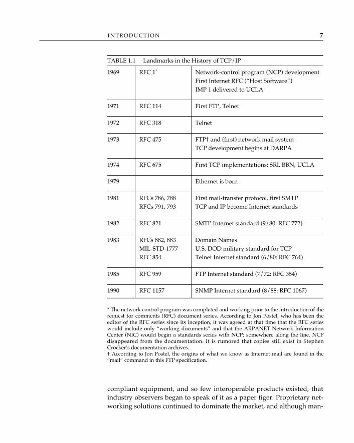
Today’s open systems have different origins as well. OSI was, fromthe beginning, intended to be the open systems networking solution.TCP/IP3 was not originally designed for such a lofty purpose; on thecontrary, it began as a private networking experiment conducted withinthe U.S. computer science research community and supported by theDepartment of Defense Advanced Research Projects Agency (ARPA),with a potential for military applications. The ARPANET may have beenthe first operational packet-switching network, but few of those whodesigned and installed the original four-node network4 in the fall of 1969anticipated that in just over two decades, from such a humble beginning,a global Internet of over 1.5 million computers and an estimated 5 millionusers would evolve. And yet practically everything we know about pack-et switching, and a good deal of what we know about distributed pro-cessing, has been affected by the research and experimentation associat-ed with the Internet. (A complete description of the history of TCP/IP isinappropriate here; for our purposes, it is sufficient to identify the land-mark achievements in the history of TCP/IP [see Table 1.1].)
TCP/IP evolved into an open systems networking alternative largelydue to the inability of the OSI standards developers to deliver the pro-mised goods in a timely fashion, for the standards kept coming, andmore were promised, but interoperable OSI implementations were hardto find. By 1984, so much hype had preceded the delivery of actual OSI-
3. The term TCP/IP is commonly used to refer either specifically to the transmissioncontrol protocol (TCP) and internet protocol (IP) or generally to the entire suite of protocolsthat have been developed by the Internet community to operate in conjunction with TCPand IP in the capital-I Internet (the global interconnection of networks running the TCP/IPprotocols) and in individual enterprise-specific “internets.”4. The four original sites were the University of California at Los Angeles (UCLA), theStanford Research Institute (SRI), the University of California at Santa Barbara (UCSB), andthe University of Utah. According to Stephen Crocker, one of the graduate students whoconnected the first host—a SIGMA VII—to the first ARPANET interface message processor(IMP) at UCLA, “An RFP was released in the summer of ‘68, and Bolt Beranek andNewman (BBN) won. The contract called for delivery of a four node network in fall ‘69with 50 (not 56) kilobit trunks. IMP 1 was delivered to UCLA prior to its scheduled deliv-ery date of 9/1/69. SRI, UCSB, and Utah followed at monthly intervals” (Stephen D.Crocker, personal correspondence, December 1991).
I N T R O D U C T I O N 7
compliant equipment, and so few interoperable products existed, thatindustry observers began to speak of it as a paper tiger. Proprietary net-working solutions continued to dominate the market, and although man-
TABLE 1.1 Landmarks in the History of TCP/IP
1969 RFC 1* Network-control program (NCP) developmentFirst Internet RFC (“Host Software”)IMP 1 delivered to UCLA
1971 RFC 114 First FTP, Telnet
1972 RFC 318 Telnet
1973 RFC 475 FTP† and (first) network mail systemTCP development begins at DARPA
1974 RFC 675 First TCP implementations: SRI, BBN, UCLA
1979 Ethernet is born
1981 RFCs 786, 788 First mail-transfer protocol, first SMTPRFCs 791, 793 TCP and IP become Internet standards
1982 RFC 821 SMTP Internet standard (9/80: RFC 772)
1983 RFCs 882, 883 Domain NamesMIL-STD-1777 U.S. DOD military standard for TCPRFC 854 Telnet Internet standard (6/80: RFC 764)
1985 RFC 959 FTP Internet standard (7/72: RFC 354)
1990 RFC 1157 SNMP Internet standard (8/88: RFC 1067)
* The network control program was completed and working prior to the introduction of therequest for comments (RFC) document series. According to Jon Postel, who has been theeditor of the RFC series since its inception, it was agreed at that time that the RFC serieswould include only “working documents” and that the ARPANET Network InformationCenter (NIC) would begin a standards series with NCP; somewhere along the line, NCPdisappeared from the documentation. It is rumored that copies still exist in StephenCrocker’s documentation archives.† According to Jon Postel, the origins of what we know as Internet mail are found in the“mail” command in this FTP specification.
O P E N S Y S T E M S N E T W O R K I N G : T C P / I P A N D O S I8
ufacturers’ marketing representatives talked a great deal about “con-forming to the OSI reference model,” their development groups man-aged to deliver only token products. The need for genuine open systemsremained unfilled and was growing. Gradually, TCP/IP ate OSI’s mid-eighties lunch, abetted in no small part by Dan Lynch’s highly successfulTCP/IP Implementers’ Workshops, which evolved into the even moresuccessful Interoperability Conferences and Exhibitions, sponsored byInterop, Inc. The first Implementers’ Workshop was held in Monterey,California, in August 1986; the first Interop conference was held in Mon-terey, in March 1987, and by 1992, the attendance at the now semiannualInterop exceeded 50,000. Interop allowed TCP/IP vendors to demon-strate real products operating in a multivendor environment on real net-works, while the OSI community endlessly debated the arcane merits offormal description techniques, conformance statements, and protocolimplementation conformance statements.
Interop was just one of many enabling vehicles for the success ofTCP/IP; the foremost was and remains the Internet infrastructure—theactual Internet, consisting of real networks and real systems—which facil-itates experimentation and research on a global scale.5 A grass-roots levelof cooperation permeates the Internet, linking academics, network pro-viders, and even the fiercest of competitors in the manufacturing sector:egos and company biases are frequently set aside to bring useful newtechnology into the Internet. This is the essence of what makes TCP/IPsuccessful today.
Still, OSI keeps coming. The promise is quietly, but inexorably,becoming a reality. All of the critical-path protocol standards have beencompleted, and OSI X.400 message handling and X.500 directory applica-tions are today operated over both pure-OSI stacks and hybrid stacks inenterprise networks and across the Internet. Real OSI products are nowdemonstrated alongside TCP/IP products at Interop as the industryattempts to shape the multiprotocol morass of today into the multiproto-col Internet of tomorrow.
Why has OSI failed to meet expectations? Unfortunately, OSI had tobe all things to all people. It had to accommodate the needs of the teletexand videotex services; integrated services digital network (ISDN); andthe government agencies and postal, telephone, and telegraph (PTT)
5. According to Larry Landweber, who keeps track of Internet connectivity throughoutthe world, 109 countries (as of summer 1992) have some sort of connectivity to the Internetthrough IP, BITNET, UUCP, OSI, or FIDONET links; of these, 46 countries have direct IPconnectivity (Landweber 1992).
I N T R O D U C T I O N 9
agencies of 20 or 30 countries. Practically every innovation that camealong in the early stages of OSI development had to be included, and thisgenerous policy of inclusion played to the detriment of OSI, compli-cating it in some cases beyond reason, creating uncertainties among pro-duct planners, and most important, sapping valuable expertise thatshould have been devoted to implementing and testing it.
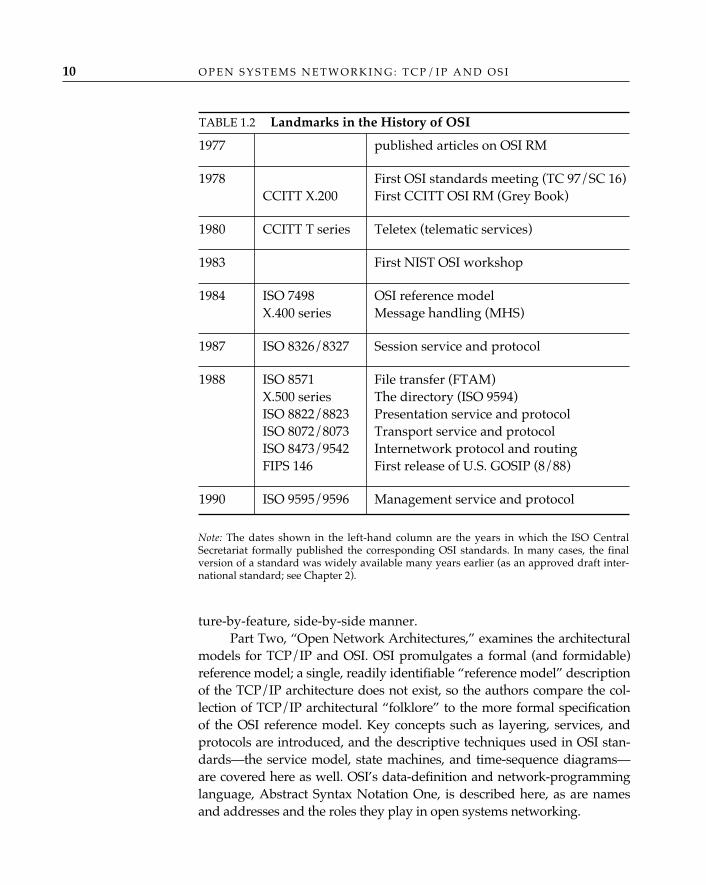
Despite these handicaps, OSI has managed to bring a variety ofvaluable new services to data networking: “white pages” directory ser-vices, a powerful network-programming language, multimedia messag-ing, and routing and addressing mechanisms that permit internets (andpotentially, the Internet) to be scaled up to very large size. These maysoon be appreciated as landmark achievements (see Table 1.2).
Open systems networking today is about OSI and TCP/IP, and per-haps other protocol stacks as well. Migration, evolution, and transitionfrom TCP/IP to OSI—marching orders from the 1980s—are regardednow as irrelevant strategies; the operative words for the 1990s (and be-yond) are coexistence and integration. The Internet is experimenting withOSI directory and message handling applications because they add value.Gateways are now provided between OSI and TCP/IP mail applicationsbecause they serve the community. OSI transport services provided byTCP and IP support OSI applications where OSI transport protocols haveyet to be deployed, and transport service bridges are used where neces-sary because it is a practical thing to do. Backbone and regional networksswitch OSI and TCP/IP datagrams, host implementations are becoming“dual-stack,” and SNMP is run over OSI because it all works. In theInternet, conformance takes a back seat to interoperability, and OSI willbe far more useful as part of the Internet than it has ever been on its own.
In Open Systems Networking: TCP/IP and OSI, the authors hope toprovide an understanding of how the components of TCP/IP and OSIwork, how they are similar and how they differ, how they came to bewhat they are today, and how they might play together in the future.There is much cause for optimism and enthusiasm, and the authors hopeto impart some of this to the readers.
Organization of This BookThe remainder of Part One, “Introduction to Open Systems,” describesthe OSI and TCP/IP standards processes (and their key participants),and establishes the convention of examining OSI and TCP/IP in a fea-
O P E N S Y S T E M S N E T W O R K I N G : T C P / I P A N D O S I10
ture-by-feature, side-by-side manner.Part Two, “Open Network Architectures,” examines the architectural
models for TCP/IP and OSI. OSI promulgates a formal (and formidable)reference model; a single, readily identifiable “reference model” descriptionof the TCP/IP architecture does not exist, so the authors compare the col-lection of TCP/IP architectural “folklore” to the more formal specificationof the OSI reference model. Key concepts such as layering, services, andprotocols are introduced, and the descriptive techniques used in OSI stan-dards—the service model, state machines, and time-sequence diagrams—are covered here as well. OSI’s data-definition and network-programminglanguage, Abstract Syntax Notation One, is described here, as are namesand addresses and the roles they play in open systems networking.
TABLE 1.2 Landmarks in the History of OSI
1977 published articles on OSI RM
1978 First OSI standards meeting (TC 97/SC 16)CCITT X.200 First CCITT OSI RM (Grey Book)
1980 CCITT T series Teletex (telematic services)
1983 First NIST OSI workshop
1984 ISO 7498 OSI reference modelX.400 series Message handling (MHS)
1987 ISO 8326/8327 Session service and protocol
1988 ISO 8571 File transfer (FTAM)X.500 series The directory (ISO 9594)ISO 8822/8823 Presentation service and protocolISO 8072/8073 Transport service and protocolISO 8473/9542 Internetwork protocol and routingFIPS 146 First release of U.S. GOSIP (8/88)
1990 ISO 9595/9596 Management service and protocol
Note: The dates shown in the left-hand column are the years in which the ISO CentralSecretariat formally published the corresponding OSI standards. In many cases, the finalversion of a standard was widely available many years earlier (as an approved draft inter-national standard; see Chapter 2).
I N T R O D U C T I O N 11
An architectural characteristic of open systems networks (as op-posed to proprietary networks) is the assumption of a set of generic, orgenerally available, applications that become building blocks (tools) forcreating more complex distributed systems. In OSI, these are called appli-cation service elements; in TCP/IP, simply “applications.” OSI and TCP/IPdiffer somewhat in the way in which applications are constructed. Thedifferences between OSI and TCP/IP application “service” architecturesare described in Part Three, “Upper Layers.” Three “daily-use” applica-tion services that are common to TCP/IP and OSI—electronic mail, direc-tories/information services, and network management—are presentedhere. An overview of the basic requirements of applications—synchro-nization, token control, connection management, activity management,remote operations, and reliable transfer—are introduced at a conceptuallevel here as well, so that readers have a general understanding of thesecapabilities to which they can refer when the specific mechanisms in thelayers that provide these capabilities (presentation and session) are dis-cussed later in the book.
Part Four, “Middle Layers,” examines how end-to-end data trans-port, internetworking, and routing are performed in OSI and TCP/IP.The similarities and differences that exist between OSI and TCP/IPtransport services, for example, are presented at a “bit level” of detail.The roots and history of the “connections versus datagrams” debate(which persists even today within the OSI community) are exposed hereas well. Rather than include an exhaustive recapitulation of readily avail-able information about existing point-to-point link and LAN technolo-gies at the data-link layer, Open Systems Networking: TCP/IP and OSIfocuses on emerging digital technologies that have been touted as broad-band6 platforms for advanced distributed applications: frame relay,FDDI, SMDS, and broadband ISDN.
Part Five, “The Future of Open Systems Networking,” attempts aHegelian synthesis of TCP/IP (thesis) and OSI (antithesis) by reviewingthe guidelines for, and politics of, building a multiprotocol Internet. Thispart describes the status of the Internet activities that are directed atexpanding the internetworking platform of the Internet to sustain itsremarkable growth and examines issues related to evolving the Internetfrom its current TCP/IP core to a system that supports internetworkingbased on OSI, XNS/IPX, and AppleTalk® as well.
6. With apologies to electrical engineers—in particular, those who are familiar with thenotion of broadband as it is applied in the world of local area networks—the term broad-band is used here in the telephony sense of the word; i.e., transmission rates in excess of 1megabit per second.
2 OPEN SYSTEMS STANDARDS
Both OSI and TCP/IP are guided by standards. The communities whodevelop standards for OSI and TCP/IP share some common practices.For example, both advance technology through a committee and consen-sus process using some form of parliamentary procedure. Both have ahierarchical infrastructure to coordinate work and enforce written (andunwritten) rules of conduct. Participation in both is international.
In other respects, these communities differ substantially, especiallywith respect to image and culture. To fully appreciate the differences,one must first understand the composition, scope, purpose, and practicesof each community.
OSI StandardsIn the late 1970s and early 1980s, the first OSI standards were developedunder Technical Committee 97 (TC 97), Information Processing, of theInternational Organization for Standardization (ISO).
Why the acronym for International Organization for Stan-dardization should be ISO, rather than IOS, is a mystery
even to standards-committee insiders. The French version of the organization’sname is Organisation Internationale de Normalisation, so the most commonexplanation for a mismatch between the name of an international standardsorganization and its acronym doesn’t apply in this case. The best explanationthe authors have heard is an analogy to the Go Children Slow traffic-sign con-
✧AHA✧
13
O P E N S Y S T E M S N E T W O R K I N G : T C P / I P A N D O S I14
vention: the most important word takes the place of honor (and in the case oftraffic signs, of motorists’ attention) in the middle.
As is the case with all ISO standards committees, the membershipof TC 97 was composed of the national standards bodies of those coun-tries that decided to participate: ANSI (the American National StandardsInstitute), for example, represented the United States; BSI (the BritishStandards Institute) represented the United Kingdom; AFNOR (theAssociation Française du Normalisation) represented France; and DIN(the Deutsches Institut für Normung) represented Germany. Within TC97, which represented primarily the interests of computer manufacturersand users, Subcommittee 16 (TC 97/SC 16) was created for the expresspurpose of working on the new area of open systems interconnection.
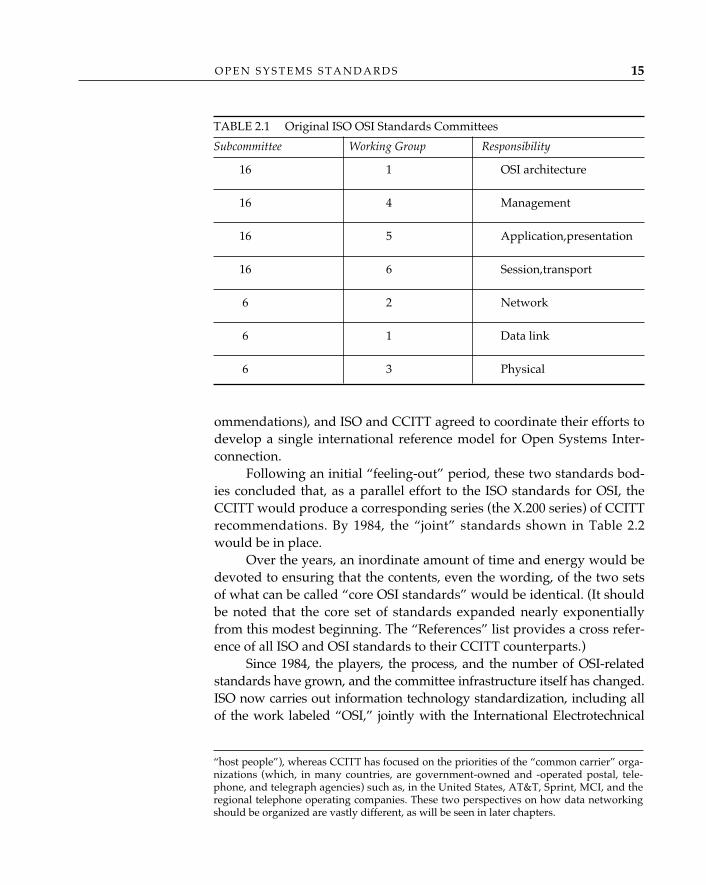
Within Subcommittee 16, the OSI reference model and generalarchitecture issues were studied in Working Group 1 (TC 97/SC 16/WG1), and “layer-specific” activities were directed to the following WGs:transport and session to WG 6, application and presentation to WG 5,and sometime later, management of OSI systems to WG 4. Althoughmost of OSI was brand new (and could therefore be assigned at will tothe brand-new Subcommittee 16), its scope also encompassed aspects oftelecommunications and data transmission for which standards workwas already well under way. Responsibility for developing OSI-relatedstandards for the network, data link, and physical layers were handedover to the existing Subcommittee 6 (Data Communications): physicalinterfaces to WG 3, data link layer to WG 1, and network layer to WG 2.This original committee structure for the development of OSI standardsis illustrated in Table 2.1.
At the time, ISO TC 97/SC 6 and Study Group VII (SG VII) of theInternational Telegraph and Telephone Consultative Committee(CCITT)1 worked closely on the development of public packet-switchingstandards (such as X.25, which is by far the best known). CCITT is aUnited Nations treaty organization and is composed primarily of tele-communication providers.2 CCITT SG VII had begun work on a messagehandling service (which would eventually become the X.400-series rec-
1. In this case, the acronym makes sense even though it does not correspond to theEnglish-language representation of the name: CCITT expands to the French Comité Consul-tatif International Télégraphique et Téléphonique. The name of this group changed to Inter-national Telecommunications Union-Telecommunications Standardization Sector in March 1993,whereupon CCITT was officially superseded by the acronym ITU-TS; throughout thisbook, however, we use the more familiar CCITT nomenclature.2. Although there is nothing in the charter of either organization that says so, ISO hashistorically focused on the priorities of computer equipment manufacturers and users (the
O P E N S Y S T E M S S T A N D A R D S 15
ommendations), and ISO and CCITT agreed to coordinate their efforts todevelop a single international reference model for Open Systems Inter-connection.
Following an initial “feeling-out” period, these two standards bod-ies concluded that, as a parallel effort to the ISO standards for OSI, theCCITT would produce a corresponding series (the X.200 series) of CCITTrecommendations. By 1984, the “joint” standards shown in Table 2.2would be in place.
Over the years, an inordinate amount of time and energy would bedevoted to ensuring that the contents, even the wording, of the two setsof what can be called “core OSI standards” would be identical. (It shouldbe noted that the core set of standards expanded nearly exponentiallyfrom this modest beginning. The “References” list provides a cross refer-ence of all ISO and OSI standards to their CCITT counterparts.)
Since 1984, the players, the process, and the number of OSI-relatedstandards have grown, and the committee infrastructure itself has changed.ISO now carries out information technology standardization, including allof the work labeled “OSI,” jointly with the International Electrotechnical
TABLE 2.1 Original ISO OSI Standards Committees
Subcommittee Working Group Responsibility
16 1 OSI architecture
16 4 Management
16 5 Application,presentation
16 6 Session,transport
6 2 Network
6 1 Data link
6 3 Physical
“host people”), whereas CCITT has focused on the priorities of the “common carrier” orga-nizations (which, in many countries, are government-owned and -operated postal, tele-phone, and telegraph agencies) such as, in the United States, AT&T, Sprint, MCI, and theregional telephone operating companies. These two perspectives on how data networkingshould be organized are vastly different, as will be seen in later chapters.
O P E N S Y S T E M S N E T W O R K I N G : T C P / I P A N D O S I16
Commission (IEC) in Joint Technical Committee 1 (ISO/IEC JTC 1), whichhas replaced TC 97. ISO/IEC still cooperates with CCITT. The TC 97Subcommittee 16 has been replaced by Subcommittee 21 (InformationRetrieval, Transfer, and Management for Open Systems Interconnection),and Subcommittee 6 has been renamed Telecommunications and Informa-tion Exchange between Systems. Typically, the participants in CCITT (offi-cially, the governments of countries that are signatories to the UnitedNations treaty that established the International TelecommunicationsUnion ITU) and ISO/IEC “national bodies” have their own national com-mittees, which submit national positions and contributions to the interna-tional standardization process represented by CCITT and ISO/IEC. In theUnited States, ANSI delegates the responsibility for actually producingstandards to accredited standards committees (ASCs): Accredited Stan-dards Committee X3 (Information Technology), for example, has responsi-bilities within the United States that are roughly equivalent to those of JointTechnical Committee 1, and within X3, X3T5 (OSI) and X3S3 (Data Com-munications) feed into SC 21 and SC 6, respectively. The ElectronicIndustries Association (EIA), Accredited Standards Committee T1 (Tele-communications), and the Institute of Electrical and Electronics Engineers(IEEE) also contribute to OSI standardization.
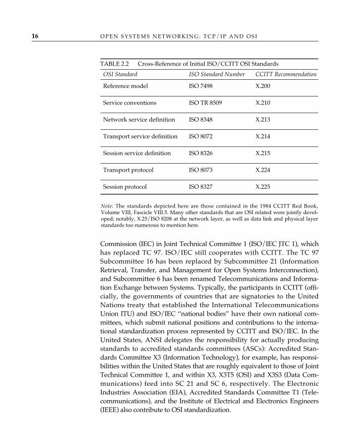
TABLE 2.2 Cross-Reference of Initial ISO/CCITT OSI Standards
OSI Standard ISO Standard Number CCITT Recommendation
Reference model ISO 7498 X.200
Service conventions ISO TR 8509 X.210
Network service definition ISO 8348 X.213
Transport service definition ISO 8072 X.214
Session service definition ISO 8326 X.215
Transport protocol ISO 8073 X.224
Session protocol ISO 8327 X.225
Note: The standards depicted here are those contained in the 1984 CCITT Red Book,Volume VIII, Fascicle VIII.5. Many other standards that are OSI related were jointly devel-oped; notably, X.25/ISO 8208 at the network layer, as well as data link and physical layerstandards too numerous to mention here.
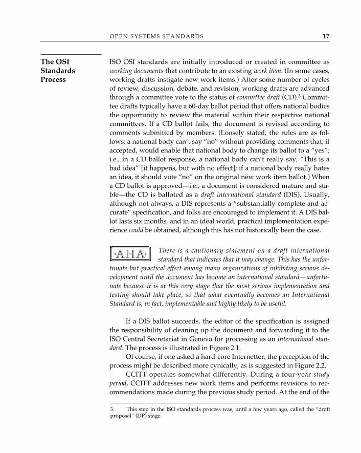
ISO OSI standards are initially introduced or created in committee asworking documents that contribute to an existing work item. (In some cases,working drafts instigate new work items.) After some number of cyclesof review, discussion, debate, and revision, working drafts are advancedthrough a committee vote to the status of committee draft (CD).3 Commit-tee drafts typically have a 60-day ballot period that offers national bodiesthe opportunity to review the material within their respective nationalcommittees. If a CD ballot fails, the document is revised according tocomments submitted by members. (Loosely stated, the rules are as fol-lows: a national body can’t say “no” without providing comments that, ifaccepted, would enable that national body to change its ballot to a “yes”;i.e., in a CD ballot response, a national body can’t really say, “This is abad idea” [it happens, but with no effect]; if a national body really hatesan idea, it should vote “no” on the original new work item ballot.) Whena CD ballot is approved—i.e., a document is considered mature and sta-ble—the CD is balloted as a draft international standard (DIS). Usually,although not always, a DIS represents a “substantially complete and ac-curate” specification, and folks are encouraged to implement it. A DIS bal-lot lasts six months, and in an ideal world, practical implementation expe-rience could be obtained, although this has not historically been the case.
There is a cautionary statement on a draft internationalstandard that indicates that it may change. This has the unfor-
tunate but practical effect among many organizations of inhibiting serious de-velopment until the document has become an international standard—unfortu-nate because it is at this very stage that the most serious implementation andtesting should take place, so that what eventually becomes an InternationalStandard is, in fact, implementable and highly likely to be useful.
If a DIS ballot succeeds, the editor of the specification is assignedthe responsibility of cleaning up the document and forwarding it to theISO Central Secretariat in Geneva for processing as an international stan-dard. The process is illustrated in Figure 2.1.
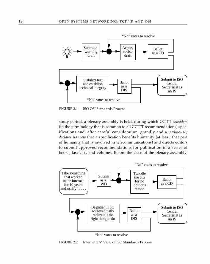
Of course, if one asked a hard-core Internetter, the perception of theprocess might be described more cynically, as is suggested in Figure 2.2.
CCITT operates somewhat differently. During a four-year studyperiod, CCITT addresses new work items and performs revisions to rec-ommendations made during the previous study period. At the end of the
✧AHA✧
O P E N S Y S T E M S S T A N D A R D S 17
The OSIStandardsProcess
3. This step in the ISO standards process was, until a few years ago, called the “draftproposal” (DP) stage.
O P E N S Y S T E M S N E T W O R K I N G : T C P / I P A N D O S I18
study period, a plenary assembly is held, during which CCITT considers(in the terminology that is common to all CCITT recommendations) spec-ifications and, after careful consideration, grandly and unanimouslydeclares its view that a specification benefits humanity (at least, that partof humanity that is involved in telecommunications) and directs editorsto submit approved recommendations for publication in a series ofbooks, fascicles, and volumes. Before the close of the plenary assembly,
FIGURE 2.1 ISO OSI Standards Process
FIGURE 2.2 Internetters’ View of ISO Standards Process
“No” votes to resolve
“No” votes to resolve
Submit aworking
draft
Argue,revisedraft
Ballotas a CD
Stabilize textand establish
technical integrity
Ballotas aDIS
Submit to ISOCentral
Secretariat asan IS
“No” votes to resolve
“No” votes to resolve
Ballotas a CD
Twiddlethe bitsfor no
obviousreason
Submitas aWD
Take somethingthat worked
in the Internetfor 10 years
and ossify it . . .
Be patient; ISOwill eventuallyrealize it’s the
right thing to do
Ballotas aDIS
Submit to ISOCentral
Secretariat asan IS
CCITT selects a pretty color for the entire series of books: thus far, pri-mary (yellow in 1980, red in 1984, blue in 1988) and secondary (orange in1976) colors have been selected. The 1992 recommendations will be pub-lished (sometime in 1993) in the White Books.
OSI standards offer choices in places where choices aren’t always best forguaranteeing the interoperability of different implementations—which ispresumably the purpose of having open systems in the first place.Shortly after it became evident that some of the choices in the OSI“stack” would result in serious noninteroperability, profile groups wereestablished to whittle down the number of implementation possibilitiesfrom a frighteningly large number of combinations to a manageable few.
Profiles are combinations of protocol and service standards with(almost) all options either prescribed or proscribed. There are:
• International standardized profiles (ISPs): ISO Technical Report10000 defines the framework and taxonomy of profiles for interna-tionally recognized (and recommended) stacks.
• Functional standards: The European Committee for Standardiza-tion/European Committee for Electrotechnical Standardization(CEN/CENELEC) develops profiles for the European EconomicCommunity (EEC).
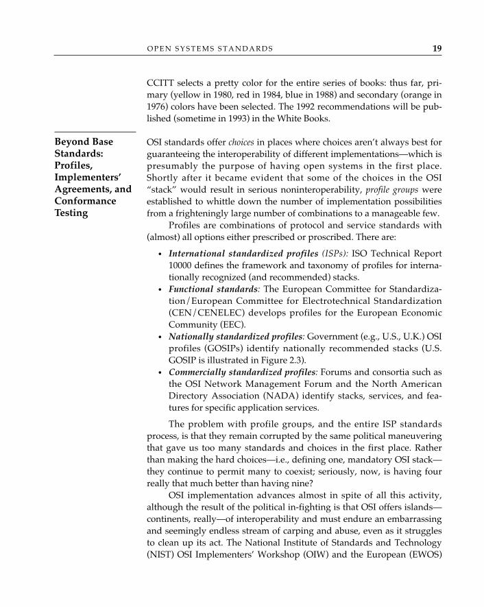
• Nationally standardized profiles: Government (e.g., U.S., U.K.) OSIprofiles (GOSIPs) identify nationally recommended stacks (U.S.GOSIP is illustrated in Figure 2.3).
• Commercially standardized profiles: Forums and consortia such asthe OSI Network Management Forum and the North AmericanDirectory Association (NADA) identify stacks, services, and fea-tures for specific application services.
The problem with profile groups, and the entire ISP standardsprocess, is that they remain corrupted by the same political maneuveringthat gave us too many standards and choices in the first place. Ratherthan making the hard choices—i.e., defining one, mandatory OSI stack—they continue to permit many to coexist; seriously, now, is having fourreally that much better than having nine?
OSI implementation advances almost in spite of all this activity,although the result of the political in-fighting is that OSI offers islands—continents, really—of interoperability and must endure an embarrassingand seemingly endless stream of carping and abuse, even as it strugglesto clean up its act. The National Institute of Standards and Technology(NIST) OSI Implementers’ Workshop (OIW) and the European (EWOS)
O P E N S Y S T E M S S T A N D A R D S 19
Beyond BaseStandards:Profiles,Implementers’Agreements, andConformanceTesting
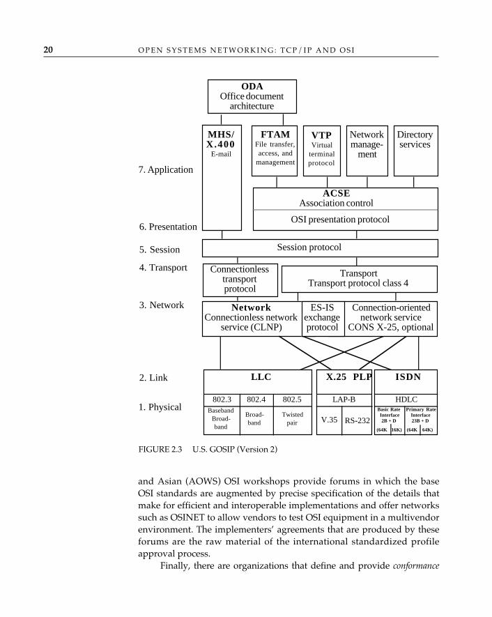
O P E N S Y S T E M S N E T W O R K I N G : T C P / I P A N D O S I20
and Asian (AOWS) OSI workshops provide forums in which the baseOSI standards are augmented by precise specification of the details thatmake for efficient and interoperable implementations and offer networkssuch as OSINET to allow vendors to test OSI equipment in a multivendorenvironment. The implementers’ agreements that are produced by theseforums are the raw material of the international standardized profileapproval process.
Finally, there are organizations that define and provide conformance
FIGURE 2.3 U.S. GOSIP (Version 2)
7. Application
6. Presentation
5. Session
4. Transport
3. Network
2. Link
1. PhysicalV.35 RS-232
ODA�Office document
architecture
MHS/X.400�
FTAM �File transfer,access, and
management
VTP �Virtual
terminalprotocol
Networkmanage-
ment
Directoryservices
ACSE�Association control
OSI presentation protocol
Session protocol
Connectionlesstransportprotocol
TransportTransport protocol class 4
Network �Connectionless network
service (CLNP)
ES-ISexchangeprotocol
Connection-orientednetwork service
CONS X-25, optional
LLC
802.3 802.4 802.5Baseband
Broad-band
Broad-band
Twistedpair
X.25 PLP
LAP-B HDLCPrimary Rate
Interface23B + D
Basic RateInterface2B + D
(64K 16K) (64K 64K)
ISDN
O P E N S Y S T E M S S T A N D A R D S 21
testing, a process in which vendors demonstrate compliance to an OSI pro-file and completeness of implementation against a “black-box” implemen-tation. Organizations like the Corporation for Open Systems (COS) andthe Standards Promotion and Applications Group (SPAG), although notstrictly the analogues of Underwriters’ Laboratory, provide such services.
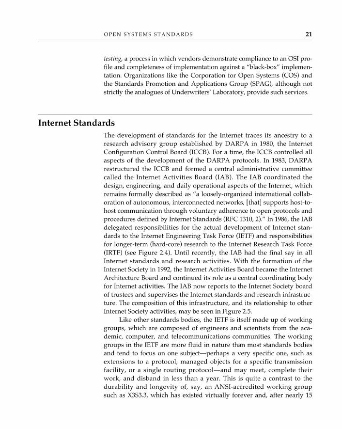
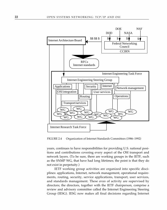
Internet Standards The development of standards for the Internet traces its ancestry to aresearch advisory group established by DARPA in 1980, the InternetConfiguration Control Board (ICCB). For a time, the ICCB controlled allaspects of the development of the DARPA protocols. In 1983, DARPArestructured the ICCB and formed a central administrative committeecalled the Internet Activities Board (IAB). The IAB coordinated thedesign, engineering, and daily operational aspects of the Internet, whichremains formally described as “a loosely-organized international collab-oration of autonomous, interconnected networks, [that] supports host-to-host communication through voluntary adherence to open protocols andprocedures defined by Internet Standards (RFC 1310, 2).” In 1986, the IABdelegated responsibilities for the actual development of Internet stan-dards to the Internet Engineering Task Force (IETF) and responsibilitiesfor longer-term (hard-core) research to the Internet Research Task Force(IRTF) (see Figure 2.4). Until recently, the IAB had the final say in allInternet standards and research activities. With the formation of theInternet Society in 1992, the Internet Activities Board became the InternetArchitecture Board and continued its role as a central coordinating bodyfor Internet activities. The IAB now reports to the Internet Society boardof trustees and supervises the Internet standards and research infrastruc-ture. The composition of this infrastructure, and its relationship to otherInternet Society activities, may be seen in Figure 2.5.
Like other standards bodies, the IETF is itself made up of workinggroups, which are composed of engineers and scientists from the aca-demic, computer, and telecommunications communities. The workinggroups in the IETF are more fluid in nature than most standards bodiesand tend to focus on one subject—perhaps a very specific one, such asextensions to a protocol, managed objects for a specific transmissionfacility, or a single routing protocol—and may meet, complete theirwork, and disband in less than a year. This is quite a contrast to thedurability and longevity of, say, an ANSI-accredited working groupsuch as X3S3.3, which has existed virtually forever and, after nearly 15
O P E N S Y S T E M S N E T W O R K I N G : T C P / I P A N D O S I22
years, continues to have responsibilities for providing U.S. national posi-tions and contributions covering every aspect of the OSI transport andnetwork layers. (To be sure, there are working groups in the IETF, suchas the SNMP WG, that have had long lifetimes; the point is that they donot exist in perpetuity.)
IETF working group activities are organized into specific disci-plines: applications, Internet, network management, operational require-ments, routing, security, service applications, transport, user services,and standards management. These areas of activity are supervised bydirectors; the directors, together with the IETF chairperson, comprise areview and advisory committee called the Internet Engineering SteeringGroup (IESG). IESG now makes all final decisions regarding Internet
$ $ $ $
CCIRN
Internet Architecture Board
DODDOE
NASANSF
Internet Research Task Force
Internet Engineering Steering Group
Internet Engineering Task Force
$$ $$ $
Federal NetworkingCouncil
RFCsInternet standards
Applications
OSI integration
Routing
Transport/services
Security Internet
User servicesNetwork management
Operations
WGWG
WG
WGWG
WG
WGWG
WG
WGWG WG
WG
WG
FIGURE 2.4 Organization of Internet Standards Committees (1986–1992)
standardization. The Internet Standards Organization (not to be con-fused with ISO!) is depicted in Figure 2.6.
TCP/IP remains a predominantly U.S.-influenced protocol suite.However, with the growth in popularity of TCP/IP, and with the in-creased interest in expanding the Internet to accommodate OSI, interna-tional organizations have demonstrated a keen interest in contributing tothe understanding, development, and deployment of internetworkingtechnology. RIPE (Réseaux IP Européens) is a forum in Europe that nur-tures expertise on IP networking. Working groups of RARE (RéseauxAssociés pour la Recherche Européene) assist the IETF in integrating OSIapplication services and protocols into the Internet. RARE is looselystructured along IETF/IESG/IAB lines of control. Much of the messagehandling, directory, and internetworking protocol (CLNP) field experi-ence obtained thus far on the Internet has been the result of cooperationbetween the IETF and RARE.
The core method of specification in the Internet is the request for comment(RFC). RFCs began as a means of documenting technical informationshortly after DARPA started the ARPANET project in 1969. The RFC“process” begins when an individual or a party (including an externalorganization) makes a document publicly available for comment; suchdocuments are called internet drafts. Internet drafts can be new ideas or
O P E N S Y S T E M S S T A N D A R D S 23
Internet Society Members(Individuals and organizations)
Board of Trustees* AdvisoryCouncil
ISOCSecretariat
Executive DirectorPublications
*OfficersPresidentVice-president (2)SecretaryTreasurer
InternetStandards & Research
Infrastructure
Committeeon Disaster
Relief
InternationalNetworkingConference
Committee onTechnologically
EmergingCountries
EditorialBoard
FIGURE 2.5 Internet Society Infrastructure
IETF “Friendsand Family”
The InternetStandardsProcess
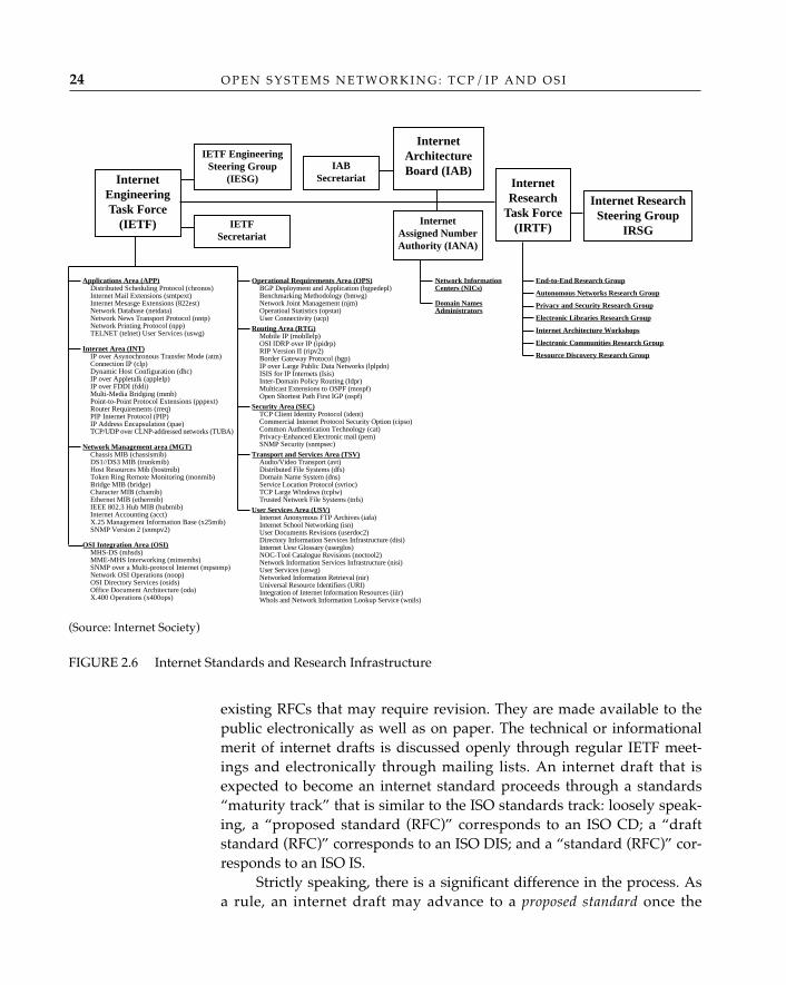
existing RFCs that may require revision. They are made available to thepublic electronically as well as on paper. The technical or informationalmerit of internet drafts is discussed openly through regular IETF meet-ings and electronically through mailing lists. An internet draft that isexpected to become an internet standard proceeds through a standards“maturity track” that is similar to the ISO standards track: loosely speak-ing, a “proposed standard (RFC)” corresponds to an ISO CD; a “draftstandard (RFC)” corresponds to an ISO DIS; and a “standard (RFC)” cor-responds to an ISO IS.
Strictly speaking, there is a significant difference in the process. Asa rule, an internet draft may advance to a proposed standard once the
O P E N S Y S T E M S N E T W O R K I N G : T C P / I P A N D O S I24
(Source: Internet Society)
FIGURE 2.6 Internet Standards and Research Infrastructure
InternetArchitectureBoard (IAB)
InternetResearch
Task Force(IRTF)
Internet ResearchSteering Group
IRSG
InternetEngineeringTask Force
(IETF)
IETF EngineeringSteering Group
(IESG)
IETFSecretariat
IABSecretariat
InternetAssigned NumberAuthority (IANA)
Applications Area (APP)Distributed Scheduling Protocol (chronos)Internet Mail Extensions (smtpext)Internet Mesasge Extensions (822est)Network Database (netdata)Network News Transport Protocol (nntp)Network Printing Protocol (npp)TELNET (telnet) User Services (uswg)
Internet Area (INT)IP over Asynochronous Transfer Mode (atm)Connection IP (clp)Dynamic Host Configuration (dhc)IP over Appletalk (applelp)IP over FDDI (fddi)Multi-Media Bridging (mmb)Point-to-Point Protocol Extensions (pppext)Router Requirements (rreq)PIP Internet Protocol (PIP)IP Address Encapsulation (ipae)TCP/UDP over CLNP-addressed networks (TUBA)
Network Management area (MGT)Chassis MIB (chassismib)DS1//DS3 MIB (trunkmib)Host Resources Mib (hostmib)Token Ring Remote Monitoring (monmib)Bridge MIB (bridge)Character MIB (chamib)Ethernet MIB (ethermib)IEEE 802.3 Hub MIB (hubmib)Internet Accounting (acct)X.25 Management Information Base (x25mib)SNMP Version 2 (snmpv2)
OSI Integration Area (OSI)MHS-DS (mhsds)MME-MHS Interworking (mimemhs)SNMP over a Multi-protocol Internet (mpsnmp)Network OSI Operations (noop)OSI Directory Services (osids)Office Document Architecture (oda)X.400 Operations (x400ops)
Operational Requirements Area (OPS)BGP Deployment and Application (bgpedepl)Benchmarking Methodology (bmwg)Network Joint Management (njm)Operatioal Statistics (opstat)User Connectivity (ucp)
Routing Area (RTG)Mobile IP (mobllelp)OSI IDRP over IP (ipidrp)RIP Version II (ripv2)Border Gateway Protocol (bgp)IP over Large Public Data Networks (lplpdn)ISIS for IP Internets (Isis)Inter-Domain Policy Routing (Idpr)Multicast Extensions to OSPF (mospf)Open Shortest Path First IGP (ospf)
Security Area (SEC)TCP Client Identity Protocol (ident)Commercial Internet Protocol Security Option (cipso)Common Authentication Technology (cat)Privacy-Enhanced Electronic mail (pem)SNMP Security (snmpsec)
Transport and Services Area (TSV)Audio/Video Transport (avt)Distributed File Systems (dfs)Domain Name System (dns)Service Location Protocol (svrioc)TCP Large Windows (tcplw)Trusted Network File Systems (tnfs)
User Services Area (USV)Internet Anonymous FTP Archives (iafa)Internet School Networking (isn)User Documents Revisions (userdoc2)Directory Information Services Infrastructure (disi)Internet Uesr Glossary (userglos)NOC-Tool Catalogue Revisions (noctool2)Network Information Services Infrastructure (nisi)User Services (uswg)Networked Information Retrieval (nir)Universal Resource Identifiers (URI)Integration of Internet Information Resources (iiir)Whols and Network Information Lookup Service (wnils)
Network InformationCenters (NICs)
Domain NamesAdministrators
End-to-End Research Group
Autonomous Networks Research Group
Privacy and Security Research Group
Electronic Libraries Research Group
Internet Architecture Workshops
Electronic Communities Research Group
Resource Discovery Research Group
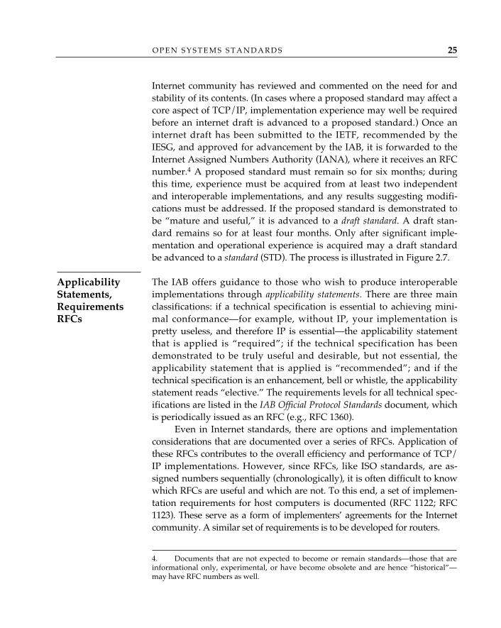
Internet community has reviewed and commented on the need for andstability of its contents. (In cases where a proposed standard may affect acore aspect of TCP/IP, implementation experience may well be requiredbefore an internet draft is advanced to a proposed standard.) Once aninternet draft has been submitted to the IETF, recommended by theIESG, and approved for advancement by the IAB, it is forwarded to theInternet Assigned Numbers Authority (IANA), where it receives an RFCnumber.4 A proposed standard must remain so for six months; duringthis time, experience must be acquired from at least two independentand interoperable implementations, and any results suggesting modifi-cations must be addressed. If the proposed standard is demonstrated tobe “mature and useful,” it is advanced to a draft standard. A draft stan-dard remains so for at least four months. Only after significant imple-mentation and operational experience is acquired may a draft standardbe advanced to a standard (STD). The process is illustrated in Figure 2.7.
The IAB offers guidance to those who wish to produce interoperableimplementations through applicability statements. There are three mainclassifications: if a technical specification is essential to achieving mini-mal conformance—for example, without IP, your implementation ispretty useless, and therefore IP is essential—the applicability statementthat is applied is “required”; if the technical specification has beendemonstrated to be truly useful and desirable, but not essential, theapplicability statement that is applied is “recommended”; and if thetechnical specification is an enhancement, bell or whistle, the applicabilitystatement reads “elective.” The requirements levels for all technical spec-ifications are listed in the IAB Official Protocol Standards document, whichis periodically issued as an RFC (e.g., RFC 1360).
Even in Internet standards, there are options and implementationconsiderations that are documented over a series of RFCs. Application ofthese RFCs contributes to the overall efficiency and performance of TCP/IP implementations. However, since RFCs, like ISO standards, are as-signed numbers sequentially (chronologically), it is often difficult to knowwhich RFCs are useful and which are not. To this end, a set of implemen-tation requirements for host computers is documented (RFC 1122; RFC1123). These serve as a form of implementers’ agreements for the Internetcommunity. A similar set of requirements is to be developed for routers.
O P E N S Y S T E M S S T A N D A R D S 25
ApplicabilityStatements,RequirementsRFCs
4. Documents that are not expected to become or remain standards—those that areinformational only, experimental, or have become obsolete and are hence “historical”—may have RFC numbers as well.
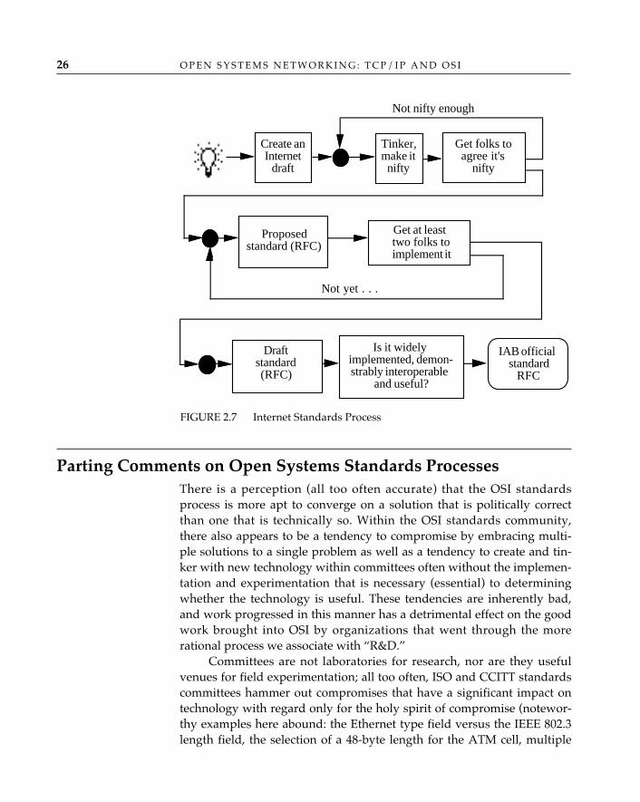
O P E N S Y S T E M S N E T W O R K I N G : T C P / I P A N D O S I26
Parting Comments on Open Systems Standards ProcessesThere is a perception (all too often accurate) that the OSI standardsprocess is more apt to converge on a solution that is politically correctthan one that is technically so. Within the OSI standards community,there also appears to be a tendency to compromise by embracing multi-ple solutions to a single problem as well as a tendency to create and tin-ker with new technology within committees often without the implemen-tation and experimentation that is necessary (essential) to determiningwhether the technology is useful. These tendencies are inherently bad,and work progressed in this manner has a detrimental effect on the goodwork brought into OSI by organizations that went through the morerational process we associate with “R&D.”
Committees are not laboratories for research, nor are they usefulvenues for field experimentation; all too often, ISO and CCITT standardscommittees hammer out compromises that have a significant impact ontechnology with regard only for the holy spirit of compromise (notewor-thy examples here abound: the Ethernet type field versus the IEEE 802.3length field, the selection of a 48-byte length for the ATM cell, multiple
Create anInternet
draft
Tinker,make itnifty
Not nifty enough
Proposedstandard (RFC)
Is it widelyimplemented, demon-strably interoperable
and useful?
IAB officialstandard
RFC
Draftstandard(RFC)
Get at leasttwo folks toimplement it
Get folks toagree it's
nifty
Not yet . . .
FIGURE 2.7 Internet Standards Process
O P E N S Y S T E M S S T A N D A R D S 27
transport protocols for conformance). Committees should confine theiractivities to evaluating proposals of some demonstrated merit, with theaim of selecting those that are most likely to solve real networking prob-lems. They should also contribute toward getting technology out of thelaboratory and into the marketplace.
The TCP/IP standards community does a better job at this than theOSI community (although this, too, is changing: as the availability of OSIproducts grows, and OSI networks grow as well, a competence in OSIoperations is slowly forming, and there is an increasing emphasis oninteroperability). In the Internet, whether it is OSI or TCP/IP or hybridsthereof, the community attempts to perpetuate the rich tradition andimage of “research and technology first.” Quite often, even internetdrafts have had some, albeit limited, field experience. And there is con-siderably less willingness to compromise in the TCP/IP community;here, there is more of a “winner-take-all” attitude, and those who havecompeting technologies often conduct what have become known asimplementation “bake-offs” to test the mettle of the alternatives. TheInternet has become a very good place for folks interested in acquiringOSI field experience.
The OSI standards community also suffers from an excessive con-cern for general applicability. Because of its international exposure, andpartly because some of the participants don’t know when to stop, OSImust support everything, and in a glorious and ultimate manner. In OSI,it often seems that solutions exhibit the properties of a gas, expanding tofill any container in which they are placed. In TCP/IP, solutions areoften more modest and incremental; you’ll never see the word simple ortrivial as part of the name of an OSI protocol, but Internet standardsdevelopers covet those modifiers and are proud to include them, when-ever possible, in the names of Internet standards.
Some of the differences between the two communities can also beattributed to size. In his defeat of the Spanish Armada in 1588, Sir FrancisDrake demonstrated that small and maneuverable corsairs could defeatsignificantly larger warships. The TCP/IP community has a similaradvantage over the OSI standards community. Although it is growing—and even today is facing some of the same difficulties that have faced theOSI standards community—the TCP/IP community has remained at avery manageable size, which allows standards makers considerable lati-tude in coming to closure on specific issues. OSI standards makers inher-ited the enormous bureaucracy that facilitated the construction of a globaltelephone service and established standards for mundane items such aswineglasses and prophylactics as well. A bake-off is a reasonable and
O P E N S Y S T E M S N E T W O R K I N G : T C P / I P A N D O S I28
eminently practical way to select a management or routing protocol partlybecause the community remains small enough that nearly everyone canunderstand and accept the results of a handful of implementations ontechnical merit alone. Bake-offs aren’t as easy to conduct when countriesthat have either recently or forever been at war are involved, especially ifthey happen to be proponents of competing technologies.
Another difference lies in composition; participation in internationalstandards making is expensive and time-consuming. Few members ofthe research community have the budget (or for that matter, the stomach)for standards work (even if more of them had, the politics of open sys-tems would remain an exasperating and significant deterrent); hence,only the big guns from the commercial sector and public providersattend.
It is also true that the stakes in standardization are different. For themoment, TCP/IP is a cash cow. From an economic standpoint, the entireTCP/IP community—network providers, equipment manufacturers, andend users—stands to profit by rapid closure on issues. At an internationallevel, however, what is profitable for one country may be unprofitablefor another, and hence, a national delegation, or community of delega-tions, attending an ISO or a CCITT meeting may have a stronger incen-tive to thwart or impede progress as a protectionist act than any vendorattending the IETF could imagine. To accommodate the needs of a largerand considerably more diverse community, OSI standards makers oftenhave little choice but to compromise in ways that in other circumstancesmight be considered incomprehensible.
There is also a difference in process. Here, the agility factor againplays in favor of the TCP/IP community. OSI is an international effort.The Internet community is largely a U.S. effort, and although the effort isbecoming more international in nature, there remains a decidedlyCaesarian attitude in the IETF—the governors of remote outposts areexpected to come to Rome to visit Caesar and not vice versa (this, too, ischanging, but slowly). Advancement of standards in OSI requires collab-oration and consensus across a very wide variety and number of individ-ual standards bodies. This translates into an overload of liaisons andmeetings. ISO/CCITT standards goers and doers have to attend dozensof meetings a year to get something done, if only to see the advancementof a standard through the process without any damaging results. ISOstandards preparation also involves translation among three languages(English, French, and Russian), which tends to slow things down—par-ticularly near the end of the process.
Finally, there is a difference in document distribution and availabilty.
O P E N S Y S T E M S S T A N D A R D S 29
TCP/IP standards are free. They can be obtained electronically throughthe Internet itself, 24 hours a day, or requests can be made for postaldelivery. There are on-line help facilities to get interested parties throughthe process. There are useful informational RFCs like the Hitchhiker’sGuide to the Internet (RFC 1118), and helpful information services organi-zations such as the Internet network information center (InterNIC).Furthermore, members of the Internet can use the existing network infra-structure to conduct useful work between meetings through mailing lists,using the very technology they standardize. ISO and CCITT standardsare difficult to identify, hard to acquire, challenging to read, and hideous-ly expensive. Consider that the full set of CCITT Blue Books is “discountpackaged” by resellers for approximately $3,000! Even the OSI MHSpackage alone costs $363. This simply doesn’t make sense: if standardsmakers want open systems, then they should be doing everything possi-ble to make standards freely available and easy to access. ISO andCCITT, and their associated national standards bodies (such as ANSI),are doing exactly the opposite. The Internet has the right idea. Inter-national standards organizations should wake up and smell the coffeebrewing.
PA R T T W O
OPEN NETWORK ARCHITECTURES
3CONCEPTS AND TERMINOLOGY OF OPEN SYSTEMS
IntroductionThroughout Open Systems Networking: TCP/IP and OSI, the terminologyand concepts of OSI are used to describe open systems architectures.Although its terminology is certainly original, most of the basic conceptsof OSI—the layered model, service definitions, hierarchical naming andaddressing, internetworking, and subnetworks—are derivative, havingbeen derived from principles that were established by other architec-tures, especially TCP/IP, and documented in different ways. The impor-tant contribution of OSI is not the concepts but the way in which theyhave been expressed in the form of a comprehensive “reference model”of open systems interconnection—the Basic Reference Model of OpenSystems Interconnection (ISO/IEC 7498: 1993).1 The use of the descriptivetools of the OSI architecture as the basis for describing the general opensystems principles of layering, naming and addressing, protocol specifi-cation, and service definition throughout this book recognizes not thatOSI as a whole is worthier than TCP/IP or other protocol suites but thatthe OSI architecture is widely known, and its terminology and conceptsare readily accepted as the basis for architectural descriptions.
The terminology and specification of TCP/IP present a strikingcontrast to OSI. The ARPA researchers (at the time they built it, DARPAwas actually ARPA) who built the first TCP/IP networks freely admitthat they were not terribly concerned with defining an architecturalmodel. Of course, over time, the urgency of formally documenting the
33
1. The new second edition of ISO/IEC 7498 will be published in 1993. It has alreadybeen published by CCITT as Recommendation X.200-1992.
O P E N S Y S T E M S N E T W O R K I N G : T C P / I P A N D O S I34
TCP/IP architecture has waned; unlike OSI, TCP/IP is defined by thereal networks (including the vast Internet) that implement it, not by therelatively few documents that describe it. Thus, although there are severallandmark journal articles that describe the architecture of TCP/IP(Cohen and Postel 1983; Cerf and Cain 1983) and a retrospective RFC(RFC 871), much of what is known about the architecture of TCP/IP re-mains folklore.2
This chapter avoids attributing basic architectural principles to anyparticular open systems architecture, focusing instead on the way inwhich those general principles are expressed by OSI and by TCP/IP. Itexamines the pleonastic3 terminology of OSI and compares it to the blue-collar language of TCP/IP and identifies the core set of terms and defini-tions that are used throughout this book. Readers will note that theauthors owe no strict allegiance to either OSI or TCP/IP. Although OSIand TCP/IP terms are used when protocol-specific terminology is neces-sary, the authors use what they believe to be the best terminology fromthe entire field of networking for the general discussion of the character-istics and principles that are common to both protocol suites.
ArchitecturesAn architecture is an abstract model of some part of the real world—inthis case, a model of the organization and behavior of networks consist-ing of interconnected, communicating computer systems and applica-tions. Because it is an abstraction, it is a useful device for describing con-cepts and relationships in a clear and concise fashion, without clutteringthe description with references to the characteristics of specific systemsor applications. The utility of such an architectural description dependson the power of the abstraction (how successfully the architecture ex-
2. In an electronic-mail exchange, Jon Postel assisted the authors’ archaeological dig forTCP/IP architectural artifacts but warned us that “any writing about the ARPANET proto-col architecture is after the fact (probably revisionist) history.” The authors interpret Jon’scomment not as an implication of TCP/IP writers in an Orwellian scheme to present adeliberately spin-controlled version of the architectural origins of TCP/IP but rather as arecognition that, for example, a paper written seven to ten years after the fact may perceivean “architectural principle” in what was really just good fortune or the result of a series ofhits and misses. In fact, of course, Jon Postel is the TCP/IP architecture; any attempt to“improve” the documentation of TCP/IP by replacing Jon with a document, however wellconstructed and thorough, would be an enormous step backward.3. At the risk of being accused of pedantry, the authors feel the word pleonastic, derivedfrom pleonasm, or “the use of more words than are necessary to express an idea,” is simplytoo accurate to eschew.
C O N C E P T S A N D T E R M I N O L O G Y O F O P E N S Y S T E M S 35
presses important concepts and relationships and suggests new ones)and on its relevance (how useful the architecture proves to be in thedevelopment of real systems and networks).
For designers and builders of networks and the distributed applica-tions that use them, the development of an architectural description ofthe environment in which the many individual components of their de-signs and implementations will interact serves two essential purposes.First, it creates a global conceptual framework within which the relation-ships among individual components can be studied and explored at acommon level of abstraction. This framework encourages broadly basedsolutions to problems, since it places each component in an abstract con-text that illuminates its interactions with other components. Second, itserves as the basis for formal descriptions of the characteristics of indi-vidual components, becoming a “global functional specification” for thedistributed environment. Like any functional specification, it establishesa common reference point for the behavior of the designs and implemen-tations that follow from it.
Open SystemsOpen systems are “open” by virtue of their mutual adherence to one ormore open systems standards, which specify those aspects of the behav-ior of an open system that are directly relevant to its ability to communi-cate with other open systems. There are many open system specificationsand standards, each of which belongs to a particular architecture (e.g.,OSI or TCP/IP). An architecture is typically described by a referencemodel, which expresses the organizing principles of the architecture (thereference points) and provides a framework (a model) within which thevarious services and protocols, and the relationships among them, maybe defined. Thus, for OSI, we have the OSI reference model (OSI RM);4 forTCP/IP, the Internet architectural model or, simply, the Internet archi-tecture.
The term architecture suggests an analogy between a referencemodel and the elements of the more familiar architecture of buildings. Abuilding-construction manual is concerned with generally applicabletruths about building: “The roof goes on the top, and the basement goes
4. Or simply RM for short. One often encounters the equivalent acronym ISORM, for“ISO reference model” (reflecting the provenance of both the OSI architecture and the asso-ciated standards), as in “ISORMites” (devout disciples and defenders of the OSI faith).
O P E N S Y S T E M S N E T W O R K I N G : T C P / I P A N D O S I36
on the bottom,” or “Plumbing is good.” This is just the accumulated wis-dom, or perhaps common sense, of the builder’s craft. A local buildingcode is much more specific: it specifies the use of a particular grade of 4-inch PVC pipe supported at no less than 1-foot intervals (etc.), or it man-dates conformance to an American Society for Testing Materials standardfor the flammability of roofing material. The blueprints for an officebuilding are even more specific: they specify, very precisely, every detailof the construction of an actual building, giving the length and placementof every piece of 4-inch PVC pipe and the brand name and stock numberof the roofing material.
The principles of construction that are collected in the manual areassumed to be universal. There are, however, a great many local buildingcodes, each of which “conforms” to the generally accepted principles ofconstruction. And within the jurisdiction of a single building code, analmost infinite variety of actual buildings can be constructed.
The OSI reference model describes both the general principles ofopen systems networking and the specific prescriptions for open systemsthat follow the OSI architecture. Like the building-construction manual,the OSI reference model collects “universal truths” about open systems:layers are good; internetworking accommodates many different types ofreal-world networks; addresses must be unambiguous. Like a buildingcode, the OSI reference model also defines an abstract model of an opensystem: not only are layers good, but OSI has seven of them; internet-working functions are in the network layer; and addresses in OSI are notonly unambiguous, they are constructed in a particular (hierarchical)fashion. However, just as a building code doesn’t describe any particularbuilding, the OSI reference model doesn’t describe any particular imple-mentation of a real open computer or communications system.
In fact, it could be argued that the scope of the OSI reference modelis even more limited than that of a building code, since it specifies onlythe externally visible behavior of an open system and carefully avoidsissues that are not directly relevant to the ability of the system to commu-nicate with other open systems. A building code might prescribe PVCpipe for drain lines in residential construction, although the requirementis actually for pipe with certain characteristics (thermal stability, resis-tance to corrosion, etc.), whether made of PVC or an equally suitablematerial. The OSI reference model specifically refrains from defining thecharacteristics of an open system, such as how to manage buffers or passinformation from one process to another, that are not relevant to theinterconnection of open systems. This restraint is essential, since suchrestrictions would be based on assumptions about the current state of the
C O N C E P T S A N D T E R M I N O L O G Y O F O P E N S Y S T E M S 37
art. In addition to reducing opportunities for competitive differentiationamong open system vendors, they might easily deter innovation in com-puter hardware and software design.
Architecture WarsThe “architecture wars” between OSI and TCP/IP involve primarily thebuilding-code aspects of open systems. Very few people get into argu-ments about whether or not plumbing is a good thing or whether or notit is useful to organize the functions of an architecture into layers; manyplumbing contractors, however, are quite willing to debate the merits ofcopper pipe over PVC, and similarly, network engineers will debatewhether security functions belong in the transport layer or the networklayer. Anyone associated with the construction business knows howmany different variations on the same basic theme can be captured bydifferent codes; nevertheless, buildings constructed according to codes inMassachusetts and Pennsylvania are (presumably) equally habitable.The differences between the OSI and the Internet architectural modelsare almost entirely variations on themes that are common to all open sys-tem architectures: layers, services, protocols, and other generally applic-able concepts from the open system cookbook.
LayersMany functions must be performed above the transmission media (the“wires”) to support useful communication between computer systems.For example, it is often necessary to ensure that the information sentfrom one computer to another arrives in order, uncorrupted, and with-out loss or duplication. If the two computers are physically attached todifferent transmission media (e.g., one to an Ethernet local area networkand another to a public, packet-switching network), it is also necessaryto define a function that selects a route and forwards data over multiple“hops” from source to destination. Additional functions encode and pre-serve the semantics and context of information as it is understood by adistributed application (a networked file service, electronic mail, or adirectory service) running on several communicating computer systems.
As an example, consider this partial list of the functions that mightbe performed by communicating computers (real-world open systems)
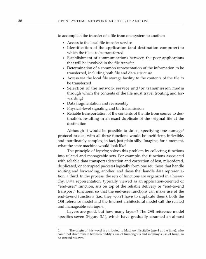
O P E N S Y S T E M S N E T W O R K I N G : T C P / I P A N D O S I38
to accomplish the transfer of a file from one system to another:
• Access to the local file transfer service• Identification of the application (and destination computer) to
which the file is to be transferred• Establishment of communications between the peer applications
that will be involved in the file transfer• Determination of a common representation of the information to be
transferred, including both file and data structure• Access via the local file storage facility to the contents of the file to
be transferred• Selection of the network service and/or transmission media
through which the contents of the file must travel (routing and for-warding)
• Data fragmentation and reassembly• Physical-level signaling and bit transmission• Reliable transportation of the contents of the file from source to des-
tination, resulting in an exact duplicate of the original file at thedestination
Although it would be possible to do so, specifying one humage5
protocol to deal with all these functions would be inefficient, inflexible,and inordinately complex; in fact, just plain silly. Imagine, for a moment,what the state machine would look like!
The principle of layering solves this problem by collecting functionsinto related and manageable sets. For example, the functions associatedwith reliable data transport (detection and correction of lost, misordered,duplicated, or corrupted packets) logically form one set; those that handlerouting and forwarding, another; and those that handle data representa-tion, a third. In the process, the sets of functions are organized in a hierar-chy. Data representation, typically viewed as an application-oriented or“end-user” function, sits on top of the reliable delivery or “end-to-endtransport” functions, so that the end-user functions can make use of theend-to-end functions (i.e., they won’t have to duplicate them). Both theOSI reference model and the Internet architectural model call the relatedand manageable sets layers.
Layers are good, but how many layers? The OSI reference modelspecifies seven (Figure 3.1), which have gradually assumed an almost
5. The origin of this word is attributed to Matthew Piscitello (age 4 at the time), whocould not discriminate between daddy’s use of humongous and mommy’s use of huge, sohe created his own.
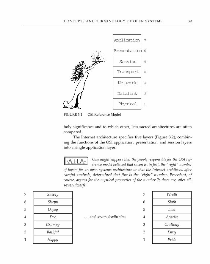
holy significance and to which other, less sacred architectures are oftencompared.
The Internet architecture specifies five layers (Figure 3.2), combin-ing the functions of the OSI application, presentation, and session layersinto a single application layer.
One might suppose that the people responsible for the OSI ref-erence model believed that seven is, in fact, the “right” number
of layers for an open systems architecture or that the Internet architects, aftercareful analysis, determined that five is the “right” number. Precedent, ofcourse, argues for the mystical properties of the number 7; there are, after all,seven dwarfs:
✧AHA✧
C O N C E P T S A N D T E R M I N O L O G Y O F O P E N S Y S T E M S 39
Application
Presentation
Session
Transport
Network
Data link
Physical
7
6
5
4
3
2
1
FIGURE 3.1 OSI Reference Model
7
6
5
4
3
2
1
7
6
5
4
3
2
1
Sneezy
Sleepy
Dopey
Doc
Grumpy
Bashful
Happy
Wrath
Sloth
Lust
Avarice
Gluttony
Envy
Pride
. . . and seven deadly sins:
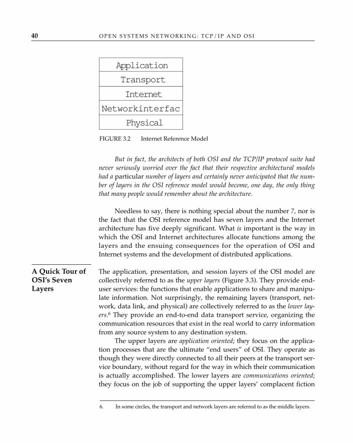
O P E N S Y S T E M S N E T W O R K I N G : T C P / I P A N D O S I40
But in fact, the architects of both OSI and the TCP/IP protocol suite hadnever seriously worried over the fact that their respective architectural modelshad a particular number of layers and certainly never anticipated that the num-ber of layers in the OSI reference model would become, one day, the only thingthat many people would remember about the architecture.
Needless to say, there is nothing special about the number 7, nor isthe fact that the OSI reference model has seven layers and the Internetarchitecture has five deeply significant. What is important is the way inwhich the OSI and Internet architectures allocate functions among thelayers and the ensuing consequences for the operation of OSI andInternet systems and the development of distributed applications.
The application, presentation, and session layers of the OSI model arecollectively referred to as the upper layers (Figure 3.3). They provide end-user services: the functions that enable applications to share and manipu-late information. Not surprisingly, the remaining layers (transport, net-work, data link, and physical) are collectively referred to as the lower lay-ers.6 They provide an end-to-end data transport service, organizing thecommunication resources that exist in the real world to carry informationfrom any source system to any destination system.
The upper layers are application oriented; they focus on the applica-tion processes that are the ultimate “end users” of OSI. They operate asthough they were directly connected to all their peers at the transport ser-vice boundary, without regard for the way in which their communicationis actually accomplished. The lower layers are communications oriented;they focus on the job of supporting the upper layers’ complacent fiction
A Quick Tour ofOSI’s SevenLayers
Application
Transport
Internet
Network interfac
Physical
FIGURE 3.2 Internet Reference Model
6. In some circles, the transport and network layers are referred to as the middle layers.
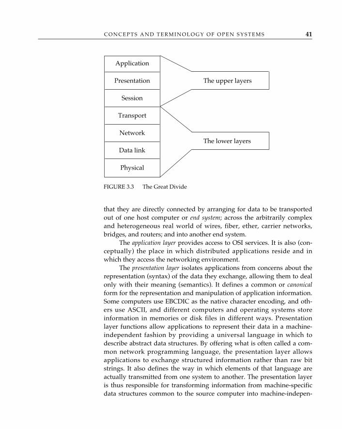
C O N C E P T S A N D T E R M I N O L O G Y O F O P E N S Y S T E M S 41
that they are directly connected by arranging for data to be transportedout of one host computer or end system; across the arbitrarily complexand heterogeneous real world of wires, fiber, ether, carrier networks,bridges, and routers; and into another end system.
The application layer provides access to OSI services. It is also (con-ceptually) the place in which distributed applications reside and inwhich they access the networking environment.
The presentation layer isolates applications from concerns about therepresentation (syntax) of the data they exchange, allowing them to dealonly with their meaning (semantics). It defines a common or canonicalform for the representation and manipulation of application information.Some computers use EBCDIC as the native character encoding, and oth-ers use ASCII, and different computers and operating systems storeinformation in memories or disk files in different ways. Presentationlayer functions allow applications to represent their data in a machine-independent fashion by providing a universal language in which todescribe abstract data structures. By offering what is often called a com-mon network programming language, the presentation layer allowsapplications to exchange structured information rather than raw bitstrings. It also defines the way in which elements of that language areactually transmitted from one system to another. The presentation layeris thus responsible for transforming information from machine-specificdata structures common to the source computer into machine-indepen-
FIGURE 3.3 The Great Divide
Application
Presentation
Session
Transport
Network
Data link
Physical
The upper layers
The lower layers
dent data structures for transmission, and from machine-independentdata structures for transmission to machine-specific data structures com-mon to the destination computer as data are received.
The session layer provides mechanisms for organizing and synchro-nizing the exchange of data between application processes. Session per-mits an application to mark its progress as it sends and receives data(synchronization points), provides ways for applications to control thedirection of information flow (turn management), coordinates multipleindependent exchanges (“activities”) within the overall context of a sin-gle session, and allows applications to inform each other about the occur-rence of errors and the steps to be taken to resynchronize part or all ofthe affected dialogue(s).
The transport layer provides “transparent transfer of data from asource end open system to a destination end open system” (ISO/IEC7498: 1993). Transport is responsible for creating and maintaining thebasic end-to-end connection between communicating open systems,ensuring that the bits delivered to the receiver are the same as the bitstransmitted by the sender: in the same order and without modification,loss, or duplication.
The network layer provides “a path between transport entities, reliev-ing the upper layers from dealing with the way in which data are trans-ferred from one end open system to another” (ISO/IEC 7498: 1993).Network determines the path or route that the data must take from origi-nal source to final destination and forwards the data over that route. Itprovides a service that is independent of the underlying transmissionmedia and includes all of the routing, relaying, and interworking functionsneeded to get from source to destination, regardless of the number or typeof transmission resources that may be used in tandem or in parallel.
The boundary between the transport and network layers wasoriginally conceived by early telephony-oriented OSI develop-
ers as a representation of the traditional regulatory boundary between customerpremises equipment (CPE) and a public carrier network: CPE contained trans-port and the upper layers, and the carrier network implemented the network andother lower-layer functions. This model assumed a pervasive global carrier net-work to which every end system was directly attached. The popularity of LANsand other privately deployed networks based on the concept of “internetwork-ing” had made this model obsolete even before the work on the OSI referencemodel was completed. The result is a network layer with an extensive internalstructure, containing both internetworking functions (which are independent of
✧AHA✧
O P E N S Y S T E M S N E T W O R K I N G : T C P / I P A N D O S I42
C O N C E P T S A N D T E R M I N O L O G Y O F O P E N S Y S T E M S 43
any particular network technology) and network-specific functions (which varydepending on the type of real-world network involved). The Internet architec-ture captures this distinction much more clearly, by defining separate “inter-net” and “network-interface” layers.
About all the OSI reference model can think of to say about the datalink layer is that it “provides for the control of the physical layer, anddetects and possibly corrects errors which may occur” (ISO/IEC 7498:1993). The data link layer couples to a particular physical access methodwhatever functions are necessary to recover bit-stream errors that maybe introduced during transmission (due to “noise,” clock jitter, cosmicrays, and other forms of signal interference).
The physical layer provides “mechanical, electrical, functional, andprocedural means to activate a physical connection for bit transmission . . .”(ISO/IEC 7498: 1993), which is OSI’s attempt to dress up the unvaryingrole of the physical layer in any network architecture: to transform bits ina computer system into electromagnetic (or equivalent) signals for a par-ticular transmission medium (wire, fiber, ether, etc.).
The data link and physical layers appear in the OSI referencemodel primarily for the sake of completeness (during the delib-
erations over the text of the reference model, it often seemed to the authors thatsomewhere, someone with considerable authority had declared, “Let there benothing in the world of communication for which OSI has no layer”). Sincethese two layers deal with functions that are so inherently specific to each indi-vidual networking technology, the layering principle of grouping together relat-ed functions is largely irrelevant. This has not, of course, prevented endlessarguments about whether there is or is not an addressing function in the datalink layer or whether medium access control for an IEEE 802 local area networkis a data link layer function or a physical layer function.
For most real network technologies, it is both impractical andunnecessary to determine where the boundary between these two layerslies or even whether to describe the functions of the real network as“data link layer functions” or “physical layer functions.” Since many realnetworks also include functions that are, from the technical standpoint ofthe OSI architecture, “in the network layer,” the TCP/IP model of realnetworks as simply individual network services is much better. OSI rec-ognized this after the fact by introducing what amounts to a codicil to its
✧AHA✧
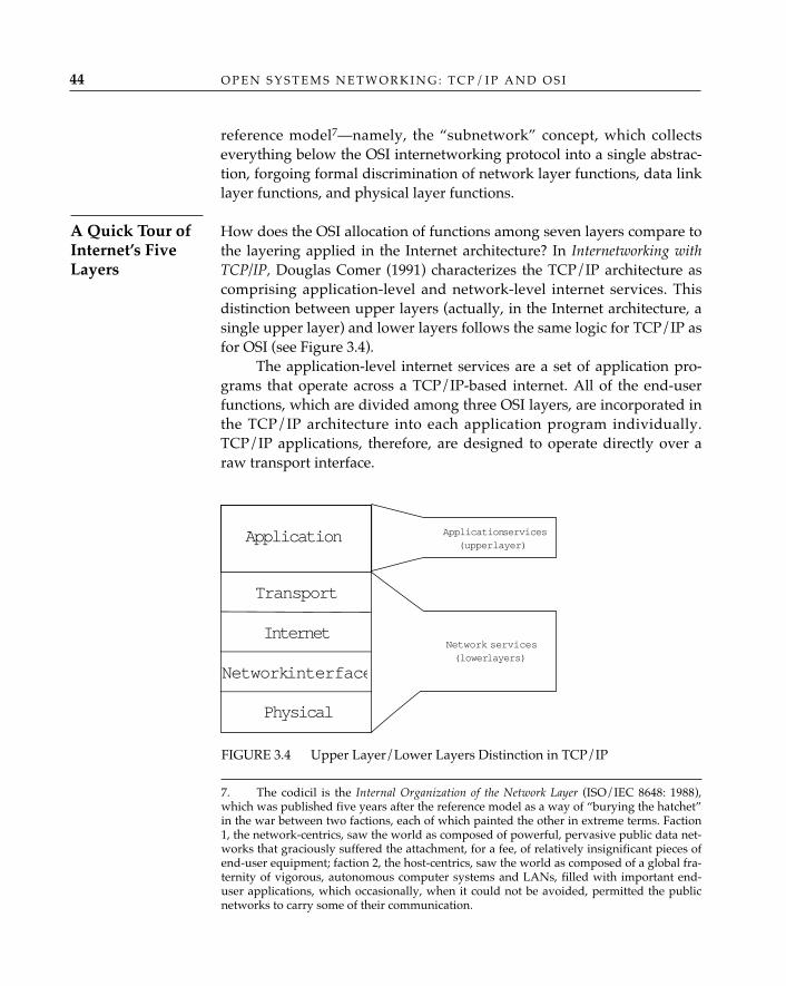
O P E N S Y S T E M S N E T W O R K I N G : T C P / I P A N D O S I44
reference model7—namely, the “subnetwork” concept, which collectseverything below the OSI internetworking protocol into a single abstrac-tion, forgoing formal discrimination of network layer functions, data linklayer functions, and physical layer functions.
How does the OSI allocation of functions among seven layers compare tothe layering applied in the Internet architecture? In Internetworking withTCP/IP, Douglas Comer (1991) characterizes the TCP/IP architecture ascomprising application-level and network-level internet services. Thisdistinction between upper layers (actually, in the Internet architecture, asingle upper layer) and lower layers follows the same logic for TCP/IP asfor OSI (see Figure 3.4).
The application-level internet services are a set of application pro-grams that operate across a TCP/IP-based internet. All of the end-userfunctions, which are divided among three OSI layers, are incorporated inthe TCP/IP architecture into each application program individually.TCP/IP applications, therefore, are designed to operate directly over araw transport interface.
A Quick Tour ofInternet’s FiveLayers
7. The codicil is the Internal Organization of the Network Layer (ISO/IEC 8648: 1988),which was published five years after the reference model as a way of “burying the hatchet”in the war between two factions, each of which painted the other in extreme terms. Faction1, the network-centrics, saw the world as composed of powerful, pervasive public data net-works that graciously suffered the attachment, for a fee, of relatively insignificant pieces ofend-user equipment; faction 2, the host-centrics, saw the world as composed of a global fra-ternity of vigorous, autonomous computer systems and LANs, filled with important end-user applications, which occasionally, when it could not be avoided, permitted the publicnetworks to carry some of their communication.
FIGURE 3.4 Upper Layer/Lower Layers Distinction in TCP/IP
Transport
Internet
Network interface
Physical
Application Application services(upper layer)
Network services(lower layers)
C O N C E P T S A N D T E R M I N O L O G Y O F O P E N S Y S T E M S 45
The network-level internet services correspond more or less directlyto the services provided by OSI’s lower layers. The OSI transport layerprovides much the same end-to-end communications service as theTCP/IP transport layer. OSI offers both virtual circuit (connection) anddatagram network layer services (see “Connections and Connectionless,”later in the chapter); TCP/IP offers only a datagram internetworking ser-vice. The network interface layer in the TCP/IP architecture correspondsto a combination of the OSI data link layer and the network-specific func-tions of the OSI network layer. The physical layer, of course, does whatthe physical layer must do.
The monolithic upper layer in the Internet architecture reflects thedeliberate involvement of the TCP/IP architecture in the way in whichdistributed applications are organized. In this respect, OSI provides amore comprehensive model. On the other hand, the correspondencebetween the lower layers of the Internet architecture and real-worldinternetworks is much clearer and more accurate than it is in the OSIcase. It has been suggested that OSI is the “better” model of distributedapplications and that TCP/IP is the “better” model for the networks thatsupport their communication.
TerminologyThe principles applied to the development of the OSI reference modelare similar to those of the TCP/IP architecture; unfortunately, the termi-nology is not. The OSI architects were convinced that none of the famil-iar terms of network engineering, freighted as they were with preexist-ing real-world connotations, would suffice for the highly formal and pre-cise descriptions they imagined for their reference model. The elusiveand mystifying world of “OSI-speak” was created to insulate the etherealand pure concept space of OSI from contamination by the existing net-works of mortals. The resulting terminology reads more like Germanexistentialism than Tanenbaum’s Computer Networks (1988).
OSI is unquestionably encumbered with too many obscure termswith confusing definitions. A definition is supposed to be “a brief andprecise description of a thing by its properties” (Thatcher and McQueen1977). OSI’s definitions are far from brief and are often imprecise; inmany cases, brevity and clarity are sacrificed for the sake of either preci-sion or political compromise. The language of TCP/IP (“Internet-ese”),on the other hand, is disarmingly accessible and bears a striking resem-blance to terms that one might use to describe real networks.
O P E N S Y S T E M S N E T W O R K I N G : T C P / I P A N D O S I46
Nevertheless, it is difficult to understand either OSI or TCP/IP with-out first becoming familiar with some of the most frequently used termi-nology. In some cases, readers need to be familiar with a term because itexpresses an important concept; in other cases, they need to be familiarwith a term because they will encounter it in the OSI standards and willotherwise be inappropriately intimidated by it. Since most of the difficultterminology belongs to OSI, most of what follows applies to that architec-ture; except where noted, the terminology of TCP/IP is intuitive.
The situation regarding terminology is similar to that inwhich Owl finds himself in the House at Pooh Corner:
Owl explained about the Necessary Dorsal Muscles. He had explained this to Poohand Christopher Robin once before, and had been waiting ever since for a chance todo it again, because it is a thing which you can easily explain twice before anybodyknows what you are talking about (Milne 1954).
EntitiesIn the OSI architecture, the service provided by a layer is, conceptually,the result of the collective activity of all the computer systems that partic-ipate in OSI. Each open system contains components (vertical slices) ofeach layer that OSI calls subsystems. A subsystem represents the function-ality of a single layer that is actually present in an individual open sys-tem. An open system therefore contains seven subsystems, each one cor-responding to one of the seven layers identified in Figure 3.1. Collectively,subsystems of the same rank form a layer.
All the functions present in a given subsystem may not be active atthe same time. For example, if a layer offers both a datagram and a virtual-circuit type of service, but only the datagram service is being used, thenonly the datagram-oriented functions of that layer are active. The activeelements within a subsystem are called entities.
In effect, an entity is the “stuff” inside a layer. Informally, the termslayer entity, entity, and layer are used interchangeably, with the under-standing that the formal meaning is “an active element within a hierar-chical division of an open system” (ISO/IEC 7498: 1993).
Given the multinational composition of the standards organi-zations responsible for OSI, it is not surprising that a great
deal of energy is expended in the selection of universally acceptable names for the
✧AHA✧
✧AHA✧
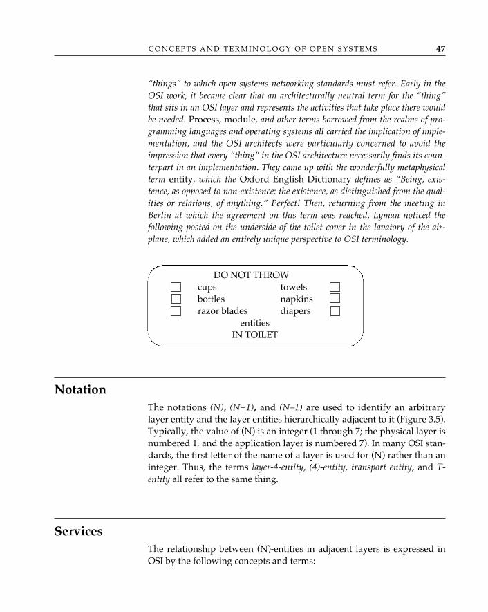
C O N C E P T S A N D T E R M I N O L O G Y O F O P E N S Y S T E M S 47
“things” to which open systems networking standards must refer. Early in theOSI work, it became clear that an architecturally neutral term for the “thing”that sits in an OSI layer and represents the activities that take place there wouldbe needed. Process, module, and other terms borrowed from the realms of pro-gramming languages and operating systems all carried the implication of imple-mentation, and the OSI architects were particularly concerned to avoid theimpression that every “thing” in the OSI architecture necessarily finds its coun-terpart in an implementation. They came up with the wonderfully metaphysicalterm entity, which the Oxford English Dictionary defines as “Being, exis-tence, as opposed to non-existence; the existence, as distinguished from the qual-ities or relations, of anything.” Perfect! Then, returning from the meeting inBerlin at which the agreement on this term was reached, Lyman noticed thefollowing posted on the underside of the toilet cover in the lavatory of the air-plane, which added an entirely unique perspective to OSI terminology.
NotationThe notations (N), (N+1), and (N–1) are used to identify an arbitrarylayer entity and the layer entities hierarchically adjacent to it (Figure 3.5).Typically, the value of (N) is an integer (1 through 7; the physical layer isnumbered 1, and the application layer is numbered 7). In many OSI stan-dards, the first letter of the name of a layer is used for (N) rather than aninteger. Thus, the terms layer-4-entity, (4)-entity, transport entity, and T-entity all refer to the same thing.
ServicesThe relationship between (N)-entities in adjacent layers is expressed inOSI by the following concepts and terms:
DO NOT THROWcups towelsbottles napkinsrazor blades diapers
entitiesIN TOILET

O P E N S Y S T E M S N E T W O R K I N G : T C P / I P A N D O S I48
• Each (N)-entity performs (N)-functions.• The (N+1)-entities assume that a well-defined set of (N)-facilities is
provided by (N)-entities.• The set of (N)-facilities that (N)-entities provide to (N+1)-entities is
called the (N)-service.
Thus, the transport layer performs transport functions and providesa set of transport facilities that constitute a transport service to the ses-sion layer. Similar terminology applies to the TCP/IP architecture; forexample, the TCP/IP internet layer provides a datagram service to thetransport layer.
OSI takes great pains to formally define services, and a service-defi-nition standard is provided for each layer. The purpose of the servicedefinition is to formally identify the functions to be performed (and thefacilities to be provided) by a layer, so that a protocol can be developedto provide a well-defined and manageable set of functions. The existenceof a formal (N)-layer service definition also assists in the design of layer(N+1), since it can be assumed that certain functions are already per-formed in layer (N) and (in theory) should not be duplicated at any layerabove (N). For example, if the transport service provides end-to-end reli-able delivery, the session layer should not.
Services provide a formal way to express the relationship that existsbetween an entity in one layer and an entity in a layer immediately aboveor below it. The OSI service model contains the following elements:
• A user of the service provided by layer (N) resides at layer (N+1),and is called an (N)-service-user.
(N)-entity
(N–1)-entity
(N+1)-entity
FIGURE 3.5 Entity Notation
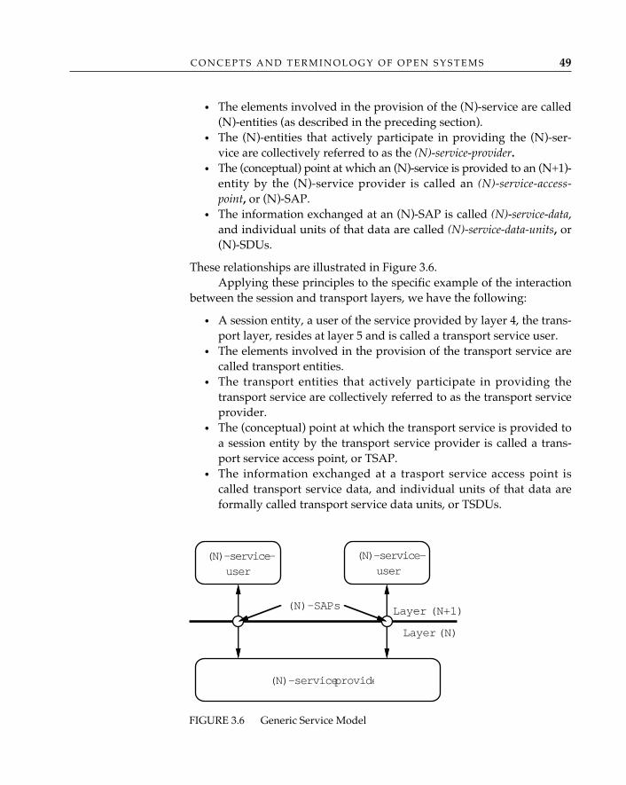
C O N C E P T S A N D T E R M I N O L O G Y O F O P E N S Y S T E M S 49
• The elements involved in the provision of the (N)-service are called(N)-entities (as described in the preceding section).
• The (N)-entities that actively participate in providing the (N)-ser-vice are collectively referred to as the (N)-service-provider.
• The (conceptual) point at which an (N)-service is provided to an (N+1)-entity by the (N)-service provider is called an (N)-service-access-point, or (N)-SAP.
• The information exchanged at an (N)-SAP is called (N)-service-data,and individual units of that data are called (N)-service-data-units, or(N)-SDUs.
These relationships are illustrated in Figure 3.6.Applying these principles to the specific example of the interaction
between the session and transport layers, we have the following:
• A session entity, a user of the service provided by layer 4, the trans-port layer, resides at layer 5 and is called a transport service user.
• The elements involved in the provision of the transport service arecalled transport entities.
• The transport entities that actively participate in providing thetransport service are collectively referred to as the transport serviceprovider.
• The (conceptual) point at which the transport service is provided toa session entity by the transport service provider is called a trans-port service access point, or TSAP.
• The information exchanged at a trasport service access point iscalled transport service data, and individual units of that data areformally called transport service data units, or TSDUs.
(N)-service provide
Layer (N+1)
Layer (N)
(N)-SAPs
(N)-service-user
(N)-service-user
FIGURE 3.6 Generic Service Model
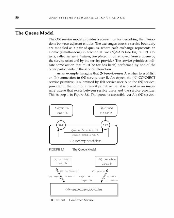
O P E N S Y S T E M S N E T W O R K I N G : T C P / I P A N D O S I50
The Queue ModelThe OSI service model provides a convention for describing the interac-tions between adjacent entities. The exchanges across a service boundaryare modeled as a pair of queues, where each exchange represents anatomic (simultaneous) interaction at two (N)-SAPs (see Figure 3.7). Ob-jects, called service primitives, are placed in or removed from a queue bythe service users and by the service provider. The service primitives indi-cate some action that must be (or has been) performed by one of theother participants in the service interaction.
As an example, imagine that (N)-service-user A wishes to establishan (N)-connection to (N)-service-user B. An object, the (N)-CONNECTservice primitive, is submitted by (N)-service-user A to the (N)-service-provider in the form of a request primitive; i.e., it is placed in an imagi-nary queue that exists between service users and the service provider.This is step 1 in Figure 3.8. The queue is accessible via A’s (N)-service-
Service provider
SAP SAP
Queue from A to B
Queue from B to A
Serviceuser A
Serviceuser B
(N)-service-provider
Layer (N+1)
Layer (N)
(1) Reques
(2) Indicat
(3) Respons(4) Confirmation
(N)-SAP B(N)-SAP A
(N)-service-user A
(N)-service-user B
FIGURE 3.7 The Queue Model
FIGURE 3.8 Confirmed Service
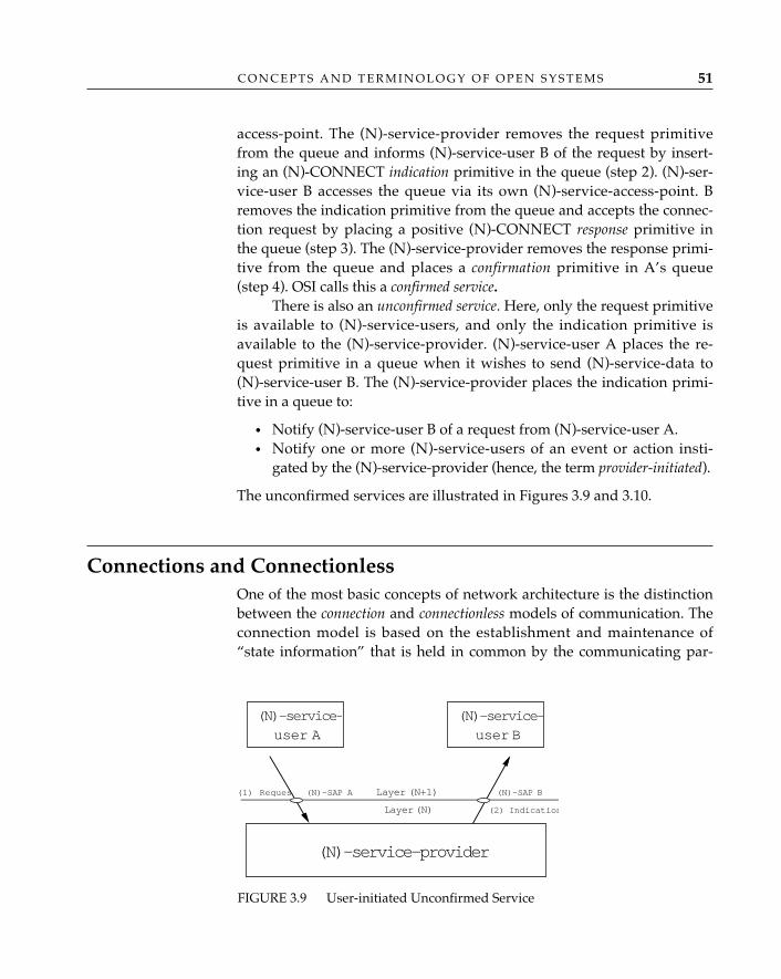
C O N C E P T S A N D T E R M I N O L O G Y O F O P E N S Y S T E M S 51
access-point. The (N)-service-provider removes the request primitivefrom the queue and informs (N)-service-user B of the request by insert-ing an (N)-CONNECT indication primitive in the queue (step 2). (N)-ser-vice-user B accesses the queue via its own (N)-service-access-point. Bremoves the indication primitive from the queue and accepts the connec-tion request by placing a positive (N)-CONNECT response primitive inthe queue (step 3). The (N)-service-provider removes the response primi-tive from the queue and places a confirmation primitive in A’s queue(step 4). OSI calls this a confirmed service.
There is also an unconfirmed service. Here, only the request primitiveis available to (N)-service-users, and only the indication primitive isavailable to the (N)-service-provider. (N)-service-user A places the re-quest primitive in a queue when it wishes to send (N)-service-data to(N)-service-user B. The (N)-service-provider places the indication primi-tive in a queue to:
• Notify (N)-service-user B of a request from (N)-service-user A.• Notify one or more (N)-service-users of an event or action insti-
gated by the (N)-service-provider (hence, the term provider-initiated).
The unconfirmed services are illustrated in Figures 3.9 and 3.10.
Connections and ConnectionlessOne of the most basic concepts of network architecture is the distinctionbetween the connection and connectionless models of communication. Theconnection model is based on the establishment and maintenance of“state information” that is held in common by the communicating par-
(N)-service-provider
Layer (N+1)
Layer (N)
(1) Reques
(2) Indication
(N)-SAP B(N)-SAP A
(N)-service-user A
(N)-service-user B
FIGURE 3.9 User-initiated Unconfirmed Service
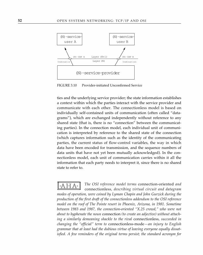
O P E N S Y S T E M S N E T W O R K I N G : T C P / I P A N D O S I52
ties and the underlying service provider; the state information establishesa context within which the parties interact with the service provider andcommunicate with each other. The connectionless model is based onindividually self-contained units of communication (often called “data-grams”), which are exchanged independently without reference to anyshared state (that is, there is no “connection” between the communicat-ing parties). In the connection model, each individual unit of communi-cation is interpreted by reference to the shared state of the connection(which captures information such as the identity of the communicatingparties, the current status of flow-control variables, the way in whichdata have been encoded for transmission, and the sequence numbers ofdata units that have not yet been mutually acknowledged). In the con-nectionless model, each unit of communication carries within it all theinformation that each party needs to interpret it, since there is no sharedstate to refer to.
The OSI reference model terms connection-oriented andconnectionless, describing virtual circuit and datagram
modes of operation, were coined by Lyman Chapin and John Gurzick during theproduction of the first draft of the connectionless addendum to the OSI referencemodel on the roof of The Pointe resort in Phoenix, Arizona, in 1981. Sometimebetween 1983 and 1987, the connection-oriented “X.25 crowd,” who were notabout to hyphenate the noun connection (to create an adjective) without attach-ing a similarly demeaning shackle to the rival connectionless, succeeded inchanging the “official” term to connectionless-mode—an injury to Englishgrammar that at least had the dubious virtue of leaving everyone equally dissat-isfied. A few reminders of the original terms persist; the standard acronym for
✧AHA✧
FIGURE 3.10 Provider-initiated Unconfirmed Service
Layer (N+1)
Layer (N)
(N)-SAP B(N)-SAP A
IndicationIndication
(N)-service-user A
(N)-service-user B
(N)-service-provider
C O N C E P T S A N D T E R M I N O L O G Y O F O P E N S Y S T E M S 53
the “connection-mode network service,” for example, is CONS, not CMNS, andthe title of ISO/IEC 8073 is “Connection-oriented Transport Protocol.”
A common mistake is to assume that either the connection modelor the connectionless model must be used uniformly throughout a net-work architecture; that is, if one layer is defined using the connectionmodel, then all the other layers must also use the connection model. Infact, the two models are complementary: it is appropriate to use the con-nection model to define a protocol in one layer (e.g., the transport layer)and the connectionless model to define a protocol in a different layer(e.g., the network layer), the combination of which can be used to pro-vide a connection-oriented (transport) service to a higher layer.
The TCP/IP and OSI architectures employ both models in all lay-ers, with one important exception: in TCP/IP, only the connectionlessmodel is used to define the services and protocols of the internet layer.The Internet architecture refers to the two models as simply “connec-tions” and “datagrams.” The OSI reference model, with its penchant for“precise” terminology, uses the terms connection-mode and connection-ori-ented for the connection model and the term connectionless-mode for theconnectionless model.
In the earliest work on OSI, communication between peer enti-ties was modeled exclusively in terms of connection-based
interactions, which were de rigueur among the telephony-oriented people8 whodominated early OSI standardization activity. Consequently, the assumptionthat a connection is a basic prerequisite for communication in OSI permeatedearly drafts of the reference model, and came to be perceived as a dominant andprerequisite feature of the OSI architecture. This widely held perception causedmany people who were familiar with the use of the connectionless model forinternetworking in TCP/IP and other architectures to dismiss OSI as applicableonly to X.25 and other connection-oriented networks. The pejorative associationof OSI with X.25 has been hard to shake, despite the fact that the connectionlessinternetworking model has been fully incorporated into the OSI architecture,
✧AHA✧
8. The temptation to attach a descriptive collective label to people with perspectives orbeliefs different from one’s own is usually irresistible, albeit deplorable; wherefore, thosewho came to OSI from traditional telephony backgrounds have been dubbed “wirestringers.” Wire stringers believe in connections (there being no such thing as “connection-less telephony”) and are skeptical of what they call “lossy datagrams”; internetworks builton the connectionless model were therefore dismissed as “academic toys.” Not surprisingly,computer nerds are as likely as normal people to succumb to petty variations on the LeeAtwater syndrome.
O P E N S Y S T E M S N E T W O R K I N G : T C P / I P A N D O S I54
and a complete set of protocols and services to support it has been defined andstandardized.
Communication using a connection proceeds through three distinctphases:
1. Connection establishment, during which the parties that intend tocommunicate negotiate and agree on the terms of their interactionand perform any necessary “setup” functions (such as the allocationof buffers, the establishment of underlying communication links,and the initialization of state variables).
2. Data transfer, during which information is exchanged according tothe rules established during connection establishment.
3. Connection release, during which the context established for commu-nication is dismantled (buffers freed, underlying links torn down,state data structures deallocated).
Connection-mode operation is based on the familiar model of a tele-phone conversation:
1. Dial the phone.2. Talk to the party at the other end.3. Hang up.
In contrast, connectionless communication has just one phase ofoperation: transmission of a single, self-contained unit of data in a pack-age that contains all relevant information. It is based on the equallyfamiliar model of the basic postal mail service: put all necessary informa-tion (address, return address, postage, “airmail” label, etc.) on the enve-lope and drop it in the mailbox slot.
Connectionless data transmission has been described disparingly as“send and pray”; but is more accurately described as “best-effort de-livery.” A service provider, be it a datagram network or a postal authority,wouldn’t last long if its users truly believed that packet or mail forwardingand delivery could only be accomplished through divine intervention.
What about Protocols?A protocol is a well-defined set of rules for what amounts to a “conversa-tion” between computer systems. The OSI architecture defines an [N]-protocol as “a set of rules and formats (semantic and syntactic) whichdetermines the communication behavior of (N)-entities in the perfor-mance of (N)-functions” (ISO/IEC 7498: 1993).
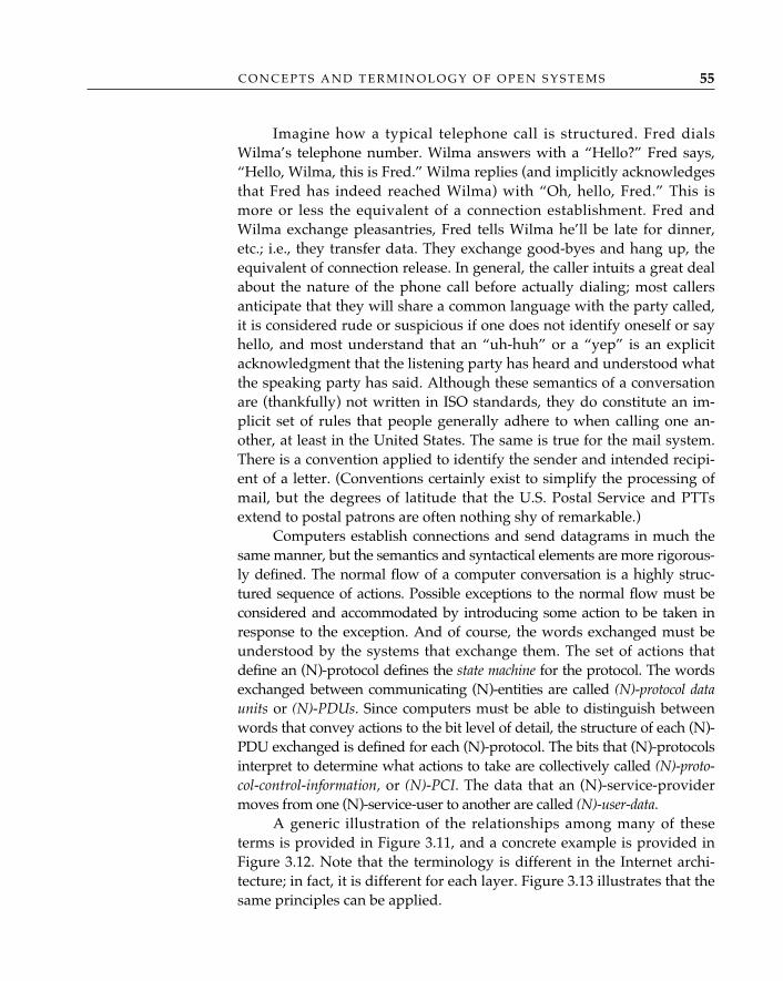
C O N C E P T S A N D T E R M I N O L O G Y O F O P E N S Y S T E M S 55
Imagine how a typical telephone call is structured. Fred dialsWilma’s telephone number. Wilma answers with a “Hello?” Fred says,“Hello, Wilma, this is Fred.” Wilma replies (and implicitly acknowledgesthat Fred has indeed reached Wilma) with “Oh, hello, Fred.” This ismore or less the equivalent of a connection establishment. Fred andWilma exchange pleasantries, Fred tells Wilma he’ll be late for dinner,etc.; i.e., they transfer data. They exchange good-byes and hang up, theequivalent of connection release. In general, the caller intuits a great dealabout the nature of the phone call before actually dialing; most callersanticipate that they will share a common language with the party called,it is considered rude or suspicious if one does not identify oneself or sayhello, and most understand that an “uh-huh” or a “yep” is an explicitacknowledgment that the listening party has heard and understood whatthe speaking party has said. Although these semantics of a conversationare (thankfully) not written in ISO standards, they do constitute an im-plicit set of rules that people generally adhere to when calling one an-other, at least in the United States. The same is true for the mail system.There is a convention applied to identify the sender and intended recipi-ent of a letter. (Conventions certainly exist to simplify the processing ofmail, but the degrees of latitude that the U.S. Postal Service and PTTsextend to postal patrons are often nothing shy of remarkable.)
Computers establish connections and send datagrams in much thesame manner, but the semantics and syntactical elements are more rigorous-ly defined. The normal flow of a computer conversation is a highly struc-tured sequence of actions. Possible exceptions to the normal flow must beconsidered and accommodated by introducing some action to be taken inresponse to the exception. And of course, the words exchanged must beunderstood by the systems that exchange them. The set of actions thatdefine an (N)-protocol defines the state machine for the protocol. The wordsexchanged between communicating (N)-entities are called (N)-protocol dataunits or (N)-PDUs. Since computers must be able to distinguish betweenwords that convey actions to the bit level of detail, the structure of each (N)-PDU exchanged is defined for each (N)-protocol. The bits that (N)-protocolsinterpret to determine what actions to take are collectively called (N)-proto-col-control-information, or (N)-PCI. The data that an (N)-service-providermoves from one (N)-service-user to another are called (N)-user-data.
A generic illustration of the relationships among many of theseterms is provided in Figure 3.11, and a concrete example is provided inFigure 3.12. Note that the terminology is different in the Internet archi-tecture; in fact, it is different for each layer. Figure 3.13 illustrates that thesame principles can be applied.
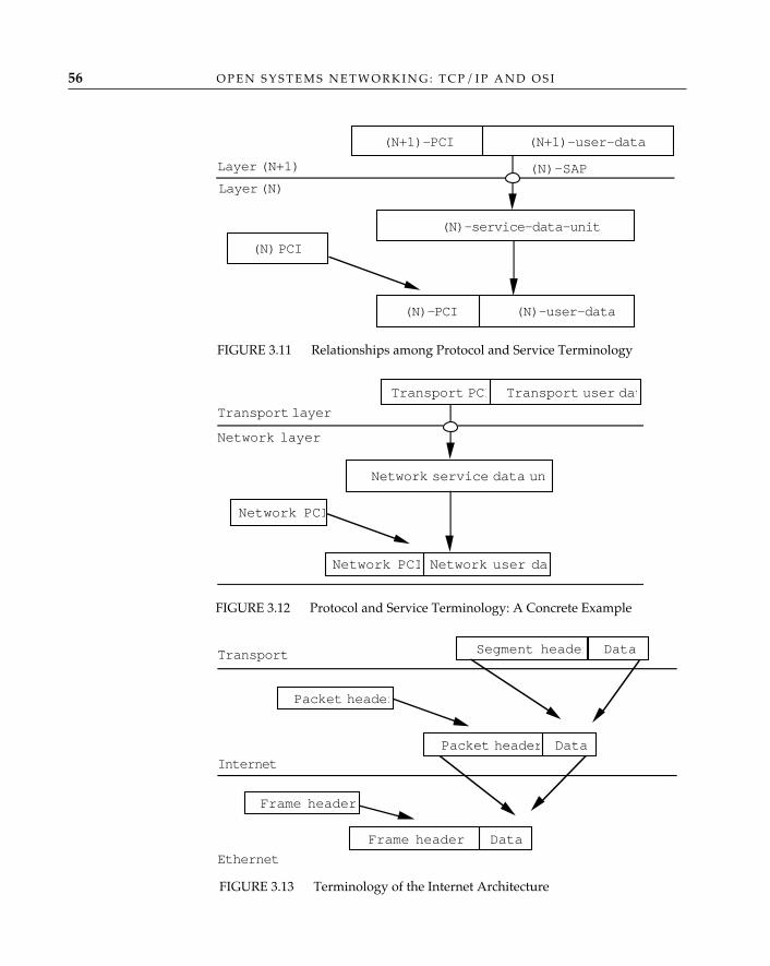
O P E N S Y S T E M S N E T W O R K I N G : T C P / I P A N D O S I56
(N+1)-PCI (N+1)-user-data
(N) PCI
(N)-service-data-unit
(N)-PCI (N)-user-data
Layer (N+1)
Layer (N)
(N)-SAP
FIGURE 3.11 Relationships among Protocol and Service Terminology
Transport PCI Transport user dat
Network PCI
Network service data un
Network user da
Transport layer
Network PCI
Network layer
FIGURE 3.12 Protocol and Service Terminology: A Concrete Example
Segment header Data
Frame header
Data
Packet header
Data
Transport
Internet
Ethernet
Packet header
Frame header
FIGURE 3.13 Terminology of the Internet Architecture
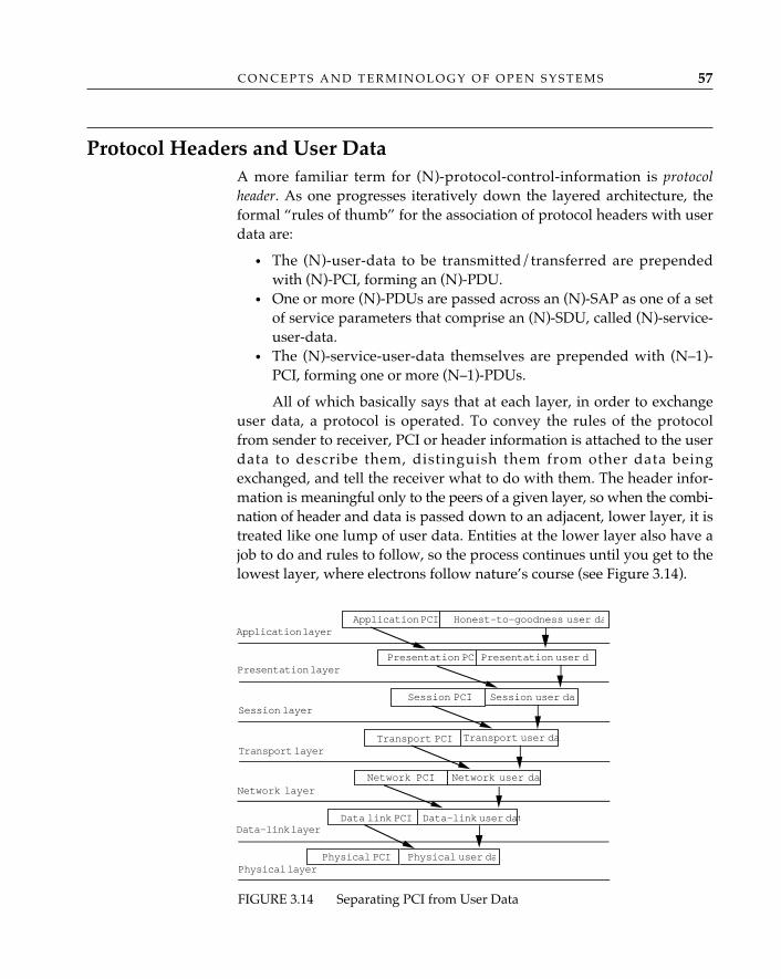
C O N C E P T S A N D T E R M I N O L O G Y O F O P E N S Y S T E M S 57
Protocol Headers and User DataA more familiar term for (N)-protocol-control-information is protocolheader. As one progresses iteratively down the layered architecture, theformal “rules of thumb” for the association of protocol headers with userdata are:
• The (N)-user-data to be transmitted/transferred are prependedwith (N)-PCI, forming an (N)-PDU.
• One or more (N)-PDUs are passed across an (N)-SAP as one of a setof service parameters that comprise an (N)-SDU, called (N)-service-user-data.
• The (N)-service-user-data themselves are prepended with (N–1)-PCI, forming one or more (N–1)-PDUs.
All of which basically says that at each layer, in order to exchangeuser data, a protocol is operated. To convey the rules of the protocolfrom sender to receiver, PCI or header information is attached to the userdata to describe them, distinguish them from other data beingexchanged, and tell the receiver what to do with them. The header infor-mation is meaningful only to the peers of a given layer, so when the combi-nation of header and data is passed down to an adjacent, lower layer, it istreated like one lump of user data. Entities at the lower layer also have ajob to do and rules to follow, so the process continues until you get to thelowest layer, where electrons follow nature’s course (see Figure 3.14).
Application PCI Honest-to-goodness user da
Session PCI Session user da
Presentation PCIPresentation user d
Transport user daTransport PCI
Network user daNetwork PCI
Data-link user datData link PCI
Physical user daPhysical PCI
Application layer
Presentation layer
Session layer
Transport layer
Network layer
Data-link layer
Physical layer
FIGURE 3.14 Separating PCI from User Data
O P E N S Y S T E M S N E T W O R K I N G : T C P / I P A N D O S I58
There are certainly those who would conclude that the developersof OSI were a bit too obsessed with protocol control information, andwry comments made during OSI standards meetings, such as “Remem-ber, we’re in the header business, not the data business . . . ,” provideanecdotal substantiation of this claim. OSI is by no means fit and trim.The expectation is that feature for feature, OSI brings enough that is newand helpful toward the goal of open distributed processing to encourageits development and use.
Relating Service to ProtocolThe relationship between a service and a protocol is straightforward: forevery primitive action, there is a related set of protocol exchanges thatenable the service provider to accomplish what it has been directed to doby its service users (or to notify its service users of exception situationsthat arise during the provision of service). This relationship is illustratedin Figure 3.15.
Note that for certain service primitives, there may be no explicitexchange of (N)-PDUs between the (N)-entities that comprise the (N)-ser-vice-provider. In this situation, the service primitive exchange models alocal action taken by a service user or the service provider; e.g., passinglocally significant parameters. For other service primitives, severalexchanges of (N)-PDUs might follow the issuance of one primitive re-quest before the associated indication is generated. In the data transferphase of the transport layer, for example, a transport PDU containingtransport user data is sent by the transport entity serving A to the trans-
(N)-SAPs
(N)-protocol(N)-entity (N)-entity
(N)-protocol
Layer (N+1)
Layer (N)
(N)-serviceuser
(N)-serviceuser
(N)-service-provider
FIGURE 3.15 Relating Service to Protocol
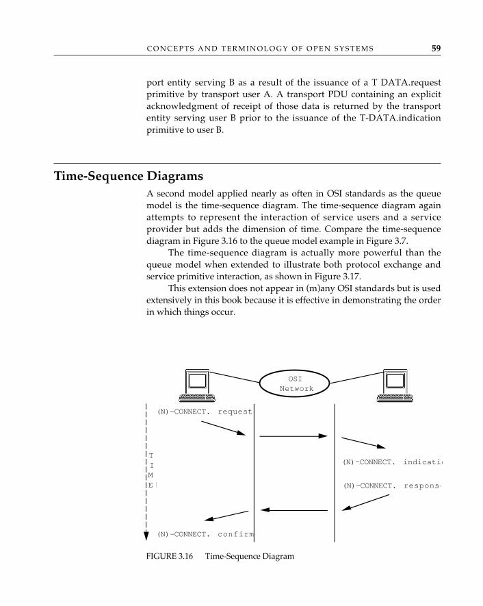
C O N C E P T S A N D T E R M I N O L O G Y O F O P E N S Y S T E M S 59
port entity serving B as a result of the issuance of a T DATA.requestprimitive by transport user A. A transport PDU containing an explicitacknowledgment of receipt of those data is returned by the transportentity serving user B prior to the issuance of the T-DATA.indicationprimitive to user B.
Time-Sequence DiagramsA second model applied nearly as often in OSI standards as the queuemodel is the time-sequence diagram. The time-sequence diagram againattempts to represent the interaction of service users and a serviceprovider but adds the dimension of time. Compare the time-sequencediagram in Figure 3.16 to the queue model example in Figure 3.7.
The time-sequence diagram is actually more powerful than thequeue model when extended to illustrate both protocol exchange andservice primitive interaction, as shown in Figure 3.17.
This extension does not appear in (m)any OSI standards but is usedextensively in this book because it is effective in demonstrating the orderin which things occur.
(N)-CONNECT. indicatio
(N)-CONNECT. response
(N)-CONNECT. request
(N)-CONNECT. confirm
TIME �
OSINetwork
FIGURE 3.16 Time-Sequence Diagram
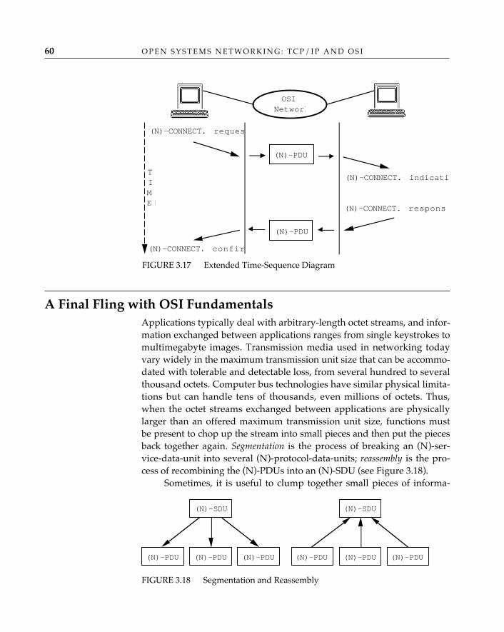
O P E N S Y S T E M S N E T W O R K I N G : T C P / I P A N D O S I60
A Final Fling with OSI FundamentalsApplications typically deal with arbitrary-length octet streams, and infor-mation exchanged between applications ranges from single keystrokes tomultimegabyte images. Transmission media used in networking todayvary widely in the maximum transmission unit size that can be accommo-dated with tolerable and detectable loss, from several hundred to severalthousand octets. Computer bus technologies have similar physical limita-tions but can handle tens of thousands, even millions of octets. Thus,when the octet streams exchanged between applications are physicallylarger than an offered maximum transmission unit size, functions mustbe present to chop up the stream into small pieces and then put the piecesback together again. Segmentation is the process of breaking an (N)-ser-vice-data-unit into several (N)-protocol-data-units; reassembly is the pro-cess of recombining the (N)-PDUs into an (N)-SDU (see Figure 3.18).
Sometimes, it is useful to clump together small pieces of informa-
(N)-CONNECT. reques
(N)-CONNECT. confir
TIME �
(N)-PDU
(N)-PDU
(N)-CONNECT. indicatio
(N)-CONNECT. respons
OSINetwork
FIGURE 3.17 Extended Time-Sequence Diagram
(N)-SDU
(N)-PDU (N)-PDU(N)-PDU
(N)-SDU
(N)-PDU(N)-PDU(N)-PDU
FIGURE 3.18 Segmentation and Reassembly
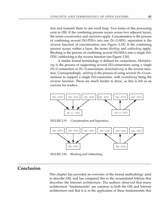
C O N C E P T S A N D T E R M I N O L O G Y O F O P E N S Y S T E M S 61
tion and transmit them in one swell foop. Two forms of this processingexist in OSI. If the combining process occurs across two adjacent layers,the terms concatenation and separation apply. Concatenation is the processof combining several (N)-PDUs into one (N–1)-SDU; separation is thereverse function of concatenation (see Figure 3.19). If the combiningprocess occurs within a layer, the terms blocking and unblocking apply.Blocking is the process of combining several (N)-SDUs into a single (N)-PDU; unblocking is the reverse function (see Figure 3.20).
A similar formal terminology is defined for connections. Multiplex-ing is the process of supporting several (N)-connections using a single(N–1) connection or (N–1)-association; demultiplexing is the reverse func-tion. Correspondingly, splitting is the process of using several (N–1)-con-nections to support a single (N)-connection, with recombining being thereverse function. These are much harder to draw, so this is left as anexercise for readers.
(N)-PDU (N)-PDU(N)-PDU(N)-PDU(N)-PDU(N)-PDU
(N–1)-SDU (N–1)-SDU
FIGURE 3.19 Concatenation and Separation
(N)-SDU
(N)-PDU (N)-PDU
(N)-SDU(N)-SDU(N)-SDU(N)-SDU(N)-SDU
FIGURE 3.20 Blocking and Unblocking
ConclusionThis chapter has provided an overview of the formal methodology usedto describe OSI, and has compared this to the accumulated folklore thatdescribes the Internet architecture. The authors observed that manyarchitectural “fundamentals” are common to both the OSI and Internetarchitectures and that it is in the application of these fundamentals that
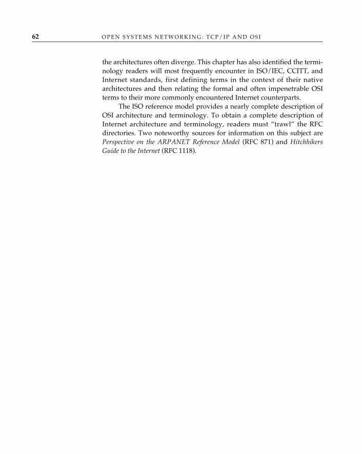
O P E N S Y S T E M S N E T W O R K I N G : T C P / I P A N D O S I62
the architectures often diverge. This chapter has also identified the termi-nology readers will most frequently encounter in ISO/IEC, CCITT, andInternet standards, first defining terms in the context of their nativearchitectures and then relating the formal and often impenetrable OSIterms to their more commonly encountered Internet counterparts.
The ISO reference model provides a nearly complete description ofOSI architecture and terminology. To obtain a complete description ofInternet architecture and terminology, readers must “trawl” the RFCdirectories. Two noteworthy sources for information on this subject arePerspective on the ARPANET Reference Model (RFC 871) and HitchhikersGuide to the Internet (RFC 1118).
4 THE LANGUAGES OFOPEN SYSTEMS
IntroductionTraditionally, data exchanged between applications across networks havebeen treated as arbitrarily long strings of “n-bit” bytes (typically, inTCP/IP and OSI, n = 8; hence, the term octet is used throughout). Appli-cations did not distinguish how data were represented as an end (user)form from the way they were transferred. This was (and remains) especial-ly true for the Internet application protocols, where the support of ASCIIas the principal character set for providing human-to-terminal interfacesevolved in such a fashion that ASCII became the de facto programming lan-guage used for defining commands and replies (protocols) for computer-to-computer applications such as electronic mail and file transfer.
Parallel to the development of the OSI protocols, a set of nonpropri-etary languages has been developed and standardized for open systemsto accommodate data representation (“abstract syntax notation”) and acorresponding encoding for data transfer (“transfer syntax”). They pro-vide a universal language for network application programming thatenables applications to exchange values of data without losing thesemantics of those data (how they are structured, what types of data arepresent in a complex data structure, how long the structure is). Theselanguages are covered in some detail in this chapter, as they illuminate anumber of differences in the approaches that have been applied to opensystems networking by the OSI and TCP/IP architectures. Readers willalso note that the languages ostensibly created for OSI have been appliedto more recently developed Internet applications, most notably in thearea of network management.
63
O P E N S Y S T E M S N E T W O R K I N G : T C P / I P A N D O S I64
Equally important to the study of languages are the practices ofnaming and addressing; the definition and representation of names arediscussed in this chapter, while the details of the overall naming andaddressing strategies of OSI and TCP/IP are described in Chapter 5. Asubpractice of naming—protocol identification (“protocol IDs”)—isdescribed in chapters in which this practice is relevant.
“Open” Languages—Breaking Language BarriersA computer vendor promoting a proprietary network architecture basedon its own products can define and use whatever terms it likes, namethings without worrying about conflicts or ambiguity, and document itswork using the descriptive notations and syntaxes that are most conve-nient for its technical writers and customer-training people. When youown the show, you can make the rules, and anyone who wants to partici-pate has to learn to speak your language. The architectural “languagebarrier” is a powerful argument for network homogeneity—one thatmany computer vendors have used to effectively exclude their competi-tors’ products from participation in networks based on their proprietaryarchitecture. Homogeneity, of course, is precisely the prison from whichthe open systems networking concept promises to release the buildersand users of networks. In order to do so, it must define and use terminol-ogy, naming schemes, and descriptive techniques—languages—that areuniversally understood.
It is hard to overemphasize the importance of languages in thedevelopment of open systems. During a meeting in 1988 of the
ISO/IEC standards committee concerned with network-layer standards(ISO/IEC JTC 1/SC 6/WG 2), the editor for one of the OSI routing protocolstandards, Dave Oran, was engaged in a discussion with another delegate aboutthe relationship between level-1 and level-2 intradomain routing. Across thetable, three Japanese delegates were following the discussion intently with thehelp of a Japanese-English dictionary. Repeatedly, Dave attempted to make whatseemed to him an obvious point; the other delegate continued to disagree withequal resolve. After several iterations, it suddenly dawned on Dave that theother delegate’s understanding of the situation was radically different from whathe had assumed, at which point he sat back and said, “Well, if that’s what youmean, then we’re really in deep sneakers!” During the brief silence that fol-lowed, one could hear the pages flipping in the dictionary as the Japanese dele-
✧AHA✧
T H E L A N G U A G E S O F O P E N S Y S T E M S 65
gates searched for the word sneakers; then a buzz of whispered consultationamong the three in Japanese and more page flipping to confirm that they hadindeed found the correct definition of sneakers. Finally, the head delegateturned to Dave and, with an expression of intense consternation, asked, “Excuseme, Mr. Editor, but please explain deep sneakers.”
The work of all the major international standards organizations, includingISO and CCITT, is conducted almost exclusively in English; non–English-speaking delegates are expected to either learn to cope in “English-as-a-second-language” mode or provide their own translations of documents (a dauntingprospect, considering the enormous amount of documentation that attends eventhe simplest standardization effort). The result is to give a significant practicaladvantage to native English speakers—and fluent non-native English speakers—in the formal standards-development process. In effect, ISO and CCITT haveadopted English as the “standard” language for standards development, with asignificant penalty for noncompliance.
Data RepresentationFive thousand years ago, the Sumerians, Babylonians, and Egyptiansencountered a problem conducting commerce in ancient Mesopotamia:although they generally agreed on the representation of simple numbers(1, 2, and 3) as recognizably similar stroke or cuneiform numerals, theydid not agree on the representation of larger numbers and did not (origi-nally) agree on syntactic markers for place value or the way in whichgraphic symbols for basic units (such as 10 and 60) should be composedto represent a numerical sum (such as the value “80” represented by thecomposition of symbols for 60 + 10 + 10). In the years since then, theproblem of unambiguously representing numerical and non-numericaldata has grown steadily worse, as the number of things demandingunambiguous representation has kept pace with the increasing complexi-ty of social and economic intercourse. The absolute literal-mindedness ofthe computer turned this problem into a genuine nightmare, but it tooknetworking to turn the problem into a nightmare of global proportions.
Although we have introduced a formal language and grammar—mathematics—the general issue of dealing with numbers has changedlittle since the time of ancient Mesopotamia. Even those who have hadlittle formal education in mathematics understand the notion of a wholenumber or an integer—no fractional parts, positives and negatives, re-member? Someone says “integer,” and we think {. . .–, –2, –1, 0, 1, 2, . . .}:
O P E N S Y S T E M S N E T W O R K I N G : T C P / I P A N D O S I66
517 is an integer, 67,190 is an integer, and Avogadro’s number1 is an inte-ger. We can pretty much grasp this without advanced degrees. Thenotion of integer in this context is abstract.
Generally speaking, programming languages such as C and Pascalhave a model of “integer” that is less abstract than the pure number-theoryconcept of “integer” but more abstract than the way in which a particularoperating system stores things that are labeled “integers” into containers(memory locations). Consider that when a mathematician says “integer,”she is dealing with the entire unconstrained concept of integer (abstract);but when a programmer says “integer” to the UNIX 4.2bsd C compiler bydeclaring a variable to be of type short, she gets a signed 15-bit containercapable of expressing “integer” values in the range –32,678 through32,767, and if she declares the variable to be of type unsigned long, shegets a 32-bit container capable of expressing “integer” values in the range0 through 232 – 1. These represent a more concrete syntax of integer—i.e.,one that is semantically bound to the machine and operating systemarchitecture on which the C program is compiled. And finally, when theC compiler generates machine-language instructions for a particular com-puter, the concept of “integer” is not even present—there is only the con-cept of binary numbers (a concrete representation) constrained to fit intocontainers of a certain size.
As a rule, when people discuss numbers, they don’t think of “con-tainers” for integers. Computers, and folks who program them, do (apreoccupation inherited in part from times when memory was a scarceand precious resource, and by today’s standards, outrageously expen-sive). Now, containers have built-in limitations on ranges of numbers; forexample, encoded in hexadecimal, the value “517” requires a 2-octet con-tainer; the value “67,190” requires 3 octets; and the value of Avogadro’snumber requires many. By and large, folks who program computers don’texpect ranges of values as broad as Avogadro’s number when they definedata constructs in programming languages like C and Pascal as part of theprocess of writing applications. Typically, they define containers thatappear to satisfy near- and modestly long-term needs. This is true forprotocols as well (protocol headers are, after all, merely another form ofdata structure). A version field of a protocol doesn’t appear to requiremore than an octet; heaven forbid we ever reach 255 versions of any sin-gle protocol and require yet another octet to encode version 256! On the
1. The number of atoms in a mole—the amount of any substance whose weight ingrams is numerically equal to its atomic or molecular weight. Avogadro’s number is 6.02 �1023.
T H E L A N G U A G E S O F O P E N S Y S T E M S 67
other hand, a 16-bit container for the window-size field of TCP, whichallowed for a 65,535-octet window, and the 32-bit sequence-number fieldseemingly satisfied long-term needs in the 1970s; with multimegabit,fiber “data pipes,” these containers are now generally regarded as toosmall.2
There is another complication when dealing with the representa-tion of numbers in computers and programming languages: even withinthe context of the same programming language, different machine archi-tectures may interpret a data structure in an entirely different manner.Take the int example. Compiling the same C program containing intdeclarations on two different machines may produce two differentresults: on a DEC PDP-11, an int without qualification is 16 bits, where-as on a VAX 11/780, an int without qualification is 32 bits, effectivelybegging the question of whether either interpretation matches the pro-grammer’s intent.
Of course, such problems extend beyond the world of whole num-bers; only some of the data we represent in computers are integers. Thevariation among machine architectures in their representation of morecomplicated data types—real numbers, complex numbers, characters,graphic strings—is even worse. This introduces yet another issue: how topreserve the semantics of information as well as the value when it isexchanged between two computers.
All of these factors make for pretty messy networking; clearly,there can be no networking of open systems without a standardized,machine-independent language in which it is possible to represent basicinformation elements in such a way that (1) the information can be inter-preted unambiguously in any context; (2) the values of data structurescan be, in principle, unbounded; and (3) the information can be con-veyed between computer systems without loss of semantics.
OSI captures the meaning (semantics) of data exchanged betweenopen systems (the abstract syntax) independently from the specificationand internal representation of that data in a computer (the concretesyntax) and the bit patterns used to transmit the data structure from onecomputer to another (the transfer syntax). The separation of abstract from
2. In RFC 1323, TCP Extensions for High Performance, Jacobson, Braden, and Bormandiscuss the problem of dealing with “long delay paths”—links with high bandwidth �delay products; over such links (e.g., SONET OC-3C [155 Mbps] and future gigabittranscontinental U.S. fiber links), the 32-bit sequence number can “wrap” dangerouslyclose to or faster than the 2-minute maximum segment limit assumed by TCP, and the 16-bit window size, which limits the effective bandwidth to 216/RTT (round-trip time) is insuf-ficient to “fill the pipe.” (Here, the U.S. transcontinental delay, approximately 60 millisec-onds, represents a hard-and-fast lower bound on RTT, which cannot be defied.)
O P E N S Y S T E M S N E T W O R K I N G : T C P / I P A N D O S I68
concrete and transfer syntax is significant in the sense that data can berepresented without concern for the container size for the data or themanner in which they are recorded in any given computer.
Abstract Syntax NotationAbstract Syntax Notation One (ASN.1 ISO/IEC 8824: 1987, which is equiva-lent to CCITT Recommendation X.208) is arguably the most widely acceptedlanguage for the representation of data for open systems networking.ASN.1 was originally developed as part of the work on OSI upper-layerstandards to serve as a uniform canonical representation of any data type(both predefined, or standardized, data types and user-defined data types),so that objects in the OSI environment—protocol headers, electronic-mailmessage headers and bodies, directory entries, management information,and virtual filestores—might be conveyed from one system to another in aform that could be understood without reference (adherence) to any specif-ic machine or operating system architecture. ASN.1 has since been adoptedas the specification language of choice by people working in areas otherthan OSI, including TCP/IP, despite the fact that it is frequently criticizedas expensive, in terms of processor cycles, to perform the transformationbetween a system’s native (hardware- and operating system–specific) rep-resentation of data and ASN.1.
Readers who are familiar with the terminology of database manage-ment will recognize ASN.1 as a data-description language. ISO/IEC 8824defines the language itself and the many predefined data types that it stan-dardizes. A companion standard, ISO/IEC 8825: 1987 (CCITT Recommen-dation X.209), defines basic encoding rules (BER) for encoding the abstractdata types of ASN.1 as actual bit streams that are exchanged by open sys-tems. Although the standards do not require the exclusive use of the ISO8825 basic encoding rules to encode ASN.1, in practice almost every encod-ing of ASN.1 is specified according to the basic encoding rules.
As a general-purpose data-description language, ASN.1 can be usedin many different ways. Its original use, especially in its earliest incarna-tion as CCITT X.409-1984, was to specify the contents of the headers ofthe OSI Message Handling System and upper-layer protocols; ASN.1descriptions are used to specify protocol data units, to define objects thatcan be used to manage network resources, and to define objects andobject attributes that can be registered and entered into a global databaseor directory. ASN.1 offers the equivalent of programming tools of gram-mar. Using ASN.1, one can construct arbitrarily complex data structures
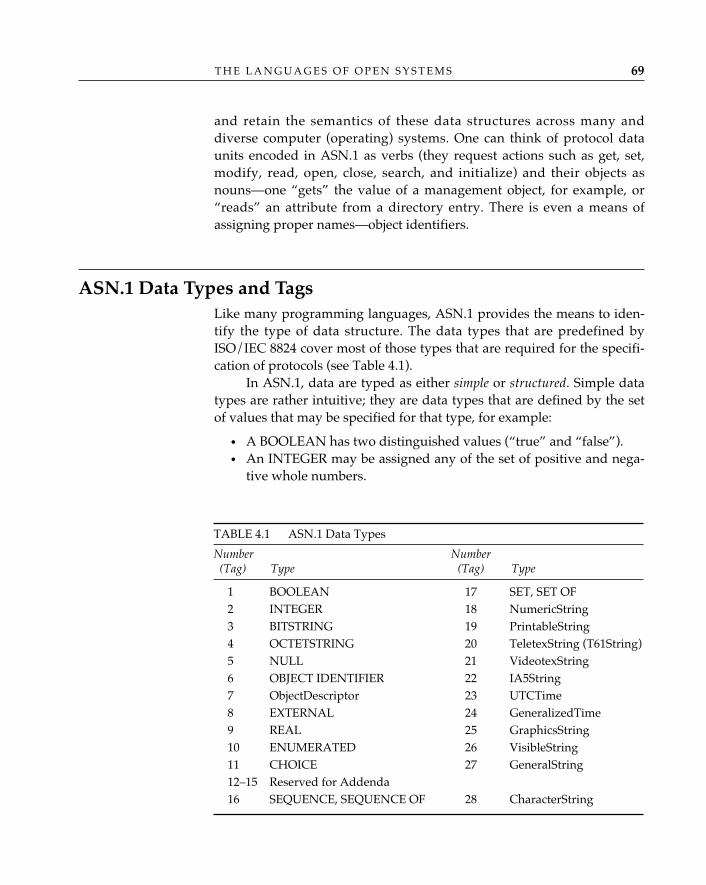
T H E L A N G U A G E S O F O P E N S Y S T E M S 69
and retain the semantics of these data structures across many anddiverse computer (operating) systems. One can think of protocol dataunits encoded in ASN.1 as verbs (they request actions such as get, set,modify, read, open, close, search, and initialize) and their objects asnouns—one “gets” the value of a management object, for example, or“reads” an attribute from a directory entry. There is even a means ofassigning proper names—object identifiers.
ASN.1 Data Types and TagsLike many programming languages, ASN.1 provides the means to iden-tify the type of data structure. The data types that are predefined byISO/IEC 8824 cover most of those types that are required for the specifi-cation of protocols (see Table 4.1).
In ASN.1, data are typed as either simple or structured. Simple datatypes are rather intuitive; they are data types that are defined by the setof values that may be specified for that type, for example:
• A BOOLEAN has two distinguished values (“true” and “false”). • An INTEGER may be assigned any of the set of positive and nega-
tive whole numbers.
TABLE 4.1 ASN.1 Data Types
Number Number(Tag) Type (Tag) Type
1 BOOLEAN 17 SET, SET OF2 INTEGER 18 NumericString3 BITSTRING 19 PrintableString4 OCTETSTRING 20 TeletexString (T61String)5 NULL 21 VideotexString6 OBJECT IDENTIFIER 22 IA5String7 ObjectDescriptor 23 UTCTime8 EXTERNAL 24 GeneralizedTime9 REAL 25 GraphicsString10 ENUMERATED 26 VisibleString11 CHOICE 27 GeneralString12–15 Reserved for Addenda16 SEQUENCE, SEQUENCE OF 28 CharacterString
O P E N S Y S T E M S N E T W O R K I N G : T C P / I P A N D O S I70
• A REAL may be assigned any of the members of the set of realnumbers—i.e., a number that can be stored in floating-point proces-sors and represented by the general formula mantissa � baseexponent.
• BITSTRING and OCTETSTRING may be composed of an orderedsequence of 0 or more bits and octets, respectively (and similarly forother character-string types—e.g., NumericString, Printable-String).
• The ever-interesting NULL may be assigned the singular value“null.”
• An ENUMERATED type is one for which a list of values is identi-fied as part of the type notation.
Structured data types are constructed from the simple data types.The availability of so many simple types alone provides for a wealth ofcombinatorial possibilities. Commonly used structured types are:
• SET, a fixed, unordered list of distinct types, some of which may beoptional.
• SET OF, an unordered list of zero or more of the same type.• SEQUENCE, a fixed, ordered list of distinct types.• SEQUENCE OF, an ordered list of zero or more of the same type.• CHOICE, like SET, a fixed, unordered list of distinct types, but in
which any instance of a CHOICE takes the value of one of the com-ponent types.
• The nefarious ANY, a CHOICE type bounded not by a list of dis-tinct types but by anything that can be defined using ASN.1, whichis often used to indicate “I dunno” or “for further study”.
Figure 4.1 provides examples of simple and structured data types.The OBJECT IDENTIFIER data type serves as the basis for a gener-
al-purpose naming scheme that can be used to identify anything that canusefully be represented in an open systems architecture as an “object.”As one might expect, there are a great many “things” in a network that canusefully be modeled as objects (borrowing at least some of the information-theoretical “object” model that has been used in, for example, object-orientedprogramming languages). Object identifiers (OIDs) serve as a uniform wayto refer unambiguously to any of these “things” (this is examined moreclosely in Chapter 5).
Each data type is assigned a unique numeric tag for unambiguousidentification within the domain of types. These are intended mainly formachine use, and they provide the data-stream identification of a datatype. There are four classes of tags. The UNIVERSAL tags are defined inISO/IEC 8824 and shown in Table 4.1. Tags that are assigned in otherOSI standards—e.g., tags that identify protocol data units of applications
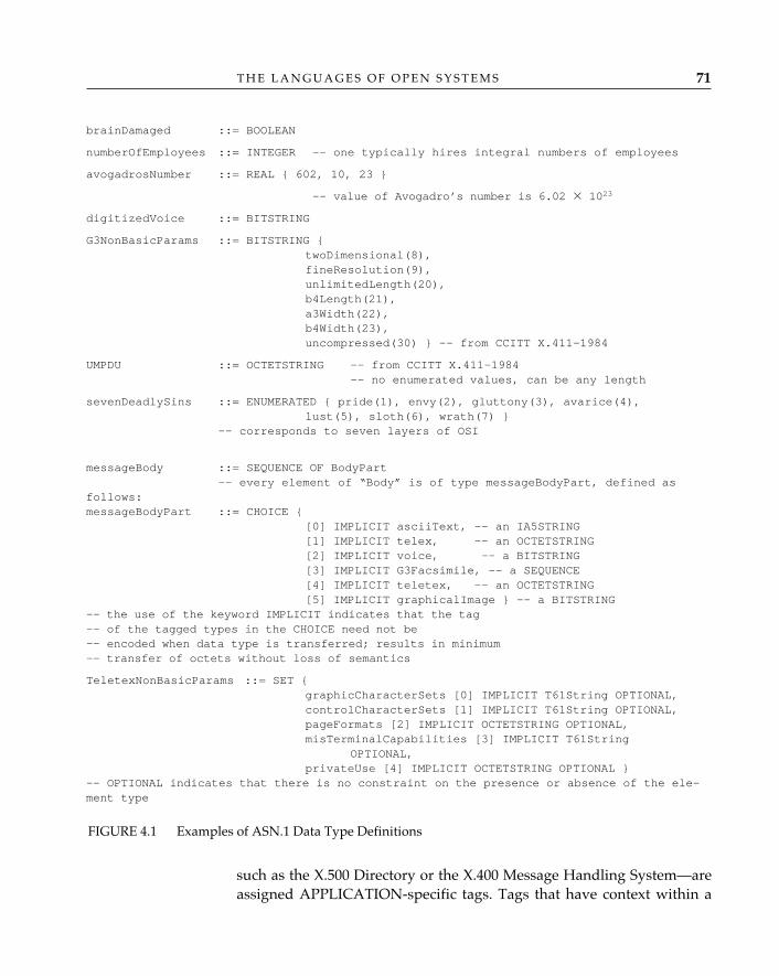
T H E L A N G U A G E S O F O P E N S Y S T E M S 71
such as the X.500 Directory or the X.400 Message Handling System—areassigned APPLICATION-specific tags. Tags that have context within a
brainDamaged ::= BOOLEAN
numberOfEmployees ::= INTEGER -- one typically hires integral numbers of employees
avogadrosNumber ::= REAL { 602, 10, 23 }
-- value of Avogadro’s number is 6.02 � 1023
digitizedVoice ::= BITSTRING
G3NonBasicParams ::= BITSTRING {twoDimensional(8),fineResolution(9),unlimitedLength(20),b4Length(21),a3Width(22),b4Width(23),uncompressed(30) } -— from CCITT X.411-1984
UMPDU ::= OCTETSTRING -- from CCITT X.411-1984-- no enumerated values, can be any length
sevenDeadlySins ::= ENUMERATED { pride(1), envy(2), gluttony(3), avarice(4), lust(5), sloth(6), wrath(7) }
-- corresponds to seven layers of OSI
messageBody ::= SEQUENCE OF BodyPart-- every element of “Body” is of type messageBodyPart, defined as
follows:messageBodyPart ::= CHOICE {
[0] IMPLICIT asciiText, -- an IA5STRING[1] IMPLICIT telex, -- an OCTETSTRING[2] IMPLICIT voice, -- a BITSTRING[3] IMPLICIT G3Facsimile, -- a SEQUENCE[4] IMPLICIT teletex, -- an OCTETSTRING[5] IMPLICIT graphicalImage } -- a BITSTRING
-- the use of the keyword IMPLICIT indicates that the tag -- of the tagged types in the CHOICE need not be-- encoded when data type is transferred; results in minimum-- transfer of octets without loss of semantics
TeletexNonBasicParams ::= SET {graphicCharacterSets [0] IMPLICIT T61String OPTIONAL,controlCharacterSets [1] IMPLICIT T61String OPTIONAL,pageFormats [2] IMPLICIT OCTETSTRING OPTIONAL,misTerminalCapabilities [3] IMPLICIT T61String
OPTIONAL,privateUse [4] IMPLICIT OCTETSTRING OPTIONAL }
-- OPTIONAL indicates that there is no constraint on the presence or absence of the ele-ment type
FIGURE 4.1 Examples of ASN.1 Data Type Definitions
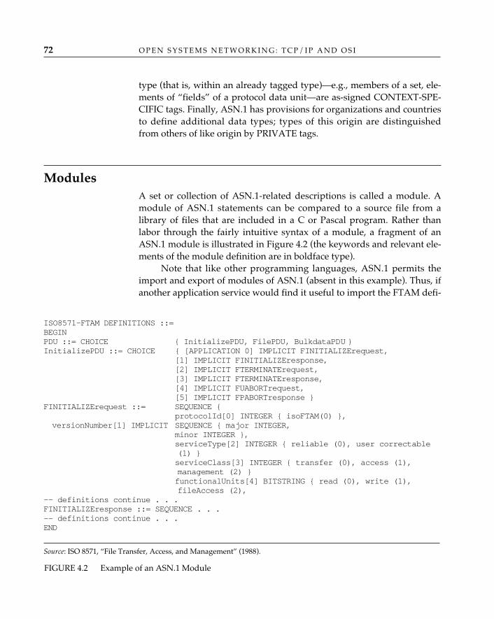
O P E N S Y S T E M S N E T W O R K I N G : T C P / I P A N D O S I72
type (that is, within an already tagged type)—e.g., members of a set, ele-ments of “fields” of a protocol data unit—are as-signed CONTEXT-SPE-CIFIC tags. Finally, ASN.1 has provisions for organizations and countriesto define additional data types; types of this origin are distinguishedfrom others of like origin by PRIVATE tags.
ModulesA set or collection of ASN.1-related descriptions is called a module. Amodule of ASN.1 statements can be compared to a source file from alibrary of files that are included in a C or Pascal program. Rather thanlabor through the fairly intuitive syntax of a module, a fragment of anASN.1 module is illustrated in Figure 4.2 (the keywords and relevant ele-ments of the module definition are in boldface type).
Note that like other programming languages, ASN.1 permits theimport and export of modules of ASN.1 (absent in this example). Thus, ifanother application service would find it useful to import the FTAM defi-
ISO8571-FTAM DEFINITIONS ::= BEGINPDU ::= CHOICE { InitializePDU, FilePDU, BulkdataPDU }InitializePDU ::= CHOICE { [APPLICATION 0] IMPLICIT FINITIALIZErequest,
[1] IMPLICIT FINITIALIZEresponse, [2] IMPLICIT FTERMINATErequest, [3] IMPLICIT FTERMINATEresponse, [4] IMPLICIT FUABORTrequest, [5] IMPLICIT FPABORTresponse }
FINITIALIZErequest ::= SEQUENCE {protocolId[0] INTEGER { isoFTAM(0) },
versionNumber[1] IMPLICIT SEQUENCE { major INTEGER, minor INTEGER }, serviceType[2] INTEGER { reliable (0), user correctable (1) } serviceClass[3] INTEGER { transfer (0), access (1), management (2) } functionalUnits[4] BITSTRING { read (0), write (1), fileAccess (2),
-- definitions continue . . .FINITIALIZEresponse ::= SEQUENCE . . . -- definitions continue . . .END
Source: ISO 8571, “File Transfer, Access, and Management” (1988).
FIGURE 4.2 Example of an ASN.1 Module
T H E L A N G U A G E S O F O P E N S Y S T E M S 73
nitions, it could do so rather than defining these same ASN.1 typesagain.
Note that in addition to a module reference or name, the DE-SCRIPTION statement may include an object identifier to provide a glob-ally unique identifier for this module. (Object identifiers are ratherunique ASN.1 simple types that provide a universal identification mech-anism and are covered under the general rubric of naming and address-ing; see Chapter 5.)
Transfer Syntax—Basic Encoding Rules (BER) for ASN.1 Constructing the bit-stream representation of the number 255 is a rela-tively simple task—eight binary 1s, and you don’t even have to worryabout the order of bit transmission. It is quite another issue to indicatealong with this bit-stream representation whether the originator of theseeight binary 1s intended that they be interpreted as the integer 255 or 1octet of a much larger integer or the “true” value of a BOOLEAN datatype or the mantissa of a real number. To preserve semantics of a datatype, to accommodate values of indefinite length, and to accommodatethe transmission of complex data structures in which component datatypes may be present or absent (OPTIONAL), encoding and transmittingthe value are simply not enough.
The bit patterns used to transmit ASN.1-encoded data types fromone computer to another—the transfer syntax—are defined in ISO/IEC8825: 1987, Specification of Basic Encoding Rules for Abstract Syntax NotationOne (ASN.1). There are three components to an encoding: the identifieror tag, the length, and the contents or value; the term TLV encoding isderived from the names of the fields of encodings (Rose 1990).
To say that the basic encoding rules are arcane is an understate-ment. Like so many aspects of OSI, the efficiency of BER has been com-promised by the perceived need for backward compatibility with itsancestor, CCITT X.409-1984. The identifier octets, which convey the typeclass and number (tag), are encoded in one of two manners. Bits 8 and 7of the initial identifier octet indicate the class—UNIVERSAL (00), APPLI-CATION (01), CONTEXT-SPECIFIC (10), or PRIVATE (11). Bit 6 identi-fies whether the data type is primitive (0) or constructed (1). The remain-ing bits of this octet contain the tag number if the number is in the range0 < tag number < 31:
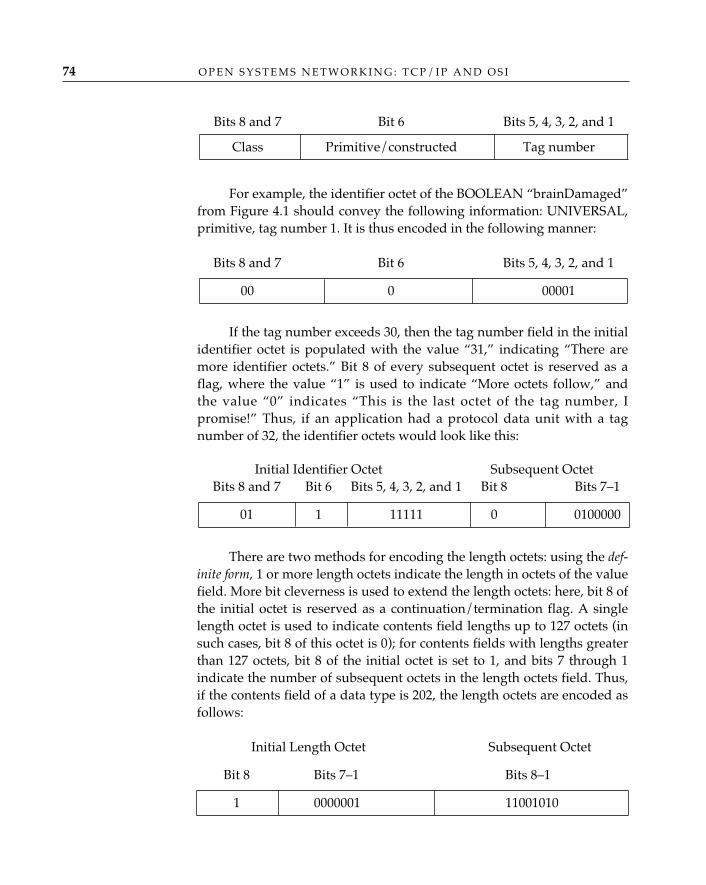
For example, the identifier octet of the BOOLEAN “brainDamaged”from Figure 4.1 should convey the following information: UNIVERSAL,primitive, tag number 1. It is thus encoded in the following manner:
If the tag number exceeds 30, then the tag number field in the initialidentifier octet is populated with the value “31,” indicating “There aremore identifier octets.” Bit 8 of every subsequent octet is reserved as aflag, where the value “1” is used to indicate “More octets follow,” andthe value “0” indicates “This is the last octet of the tag number, Ipromise!” Thus, if an application had a protocol data unit with a tagnumber of 32, the identifier octets would look like this:
There are two methods for encoding the length octets: using the def-inite form, 1 or more length octets indicate the length in octets of the valuefield. More bit cleverness is used to extend the length octets: here, bit 8 ofthe initial octet is reserved as a continuation/termination flag. A singlelength octet is used to indicate contents field lengths up to 127 octets (insuch cases, bit 8 of this octet is 0); for contents fields with lengths greaterthan 127 octets, bit 8 of the initial octet is set to 1, and bits 7 through 1indicate the number of subsequent octets in the length octets field. Thus,if the contents field of a data type is 202, the length octets are encoded asfollows:
Initial Length Octet Subsequent Octet
Bit 8 Bits 7–1 Bits 8–1
1 0000001 11001010
Bits 8 and 7 Bit 6 Bits 5, 4, 3, 2, and 1
00 0 00001
Bits 8 and 7 Bit 6 Bits 5, 4, 3, 2, and 1
Class Primitive/constructed Tag number
Initial Identifier Octet Subsequent OctetBits 8 and 7 Bit 6 Bits 5, 4, 3, 2, and 1 Bit 8 Bits 7–1
01 1 11111 0 0100000
O P E N S Y S T E M S N E T W O R K I N G : T C P / I P A N D O S I74
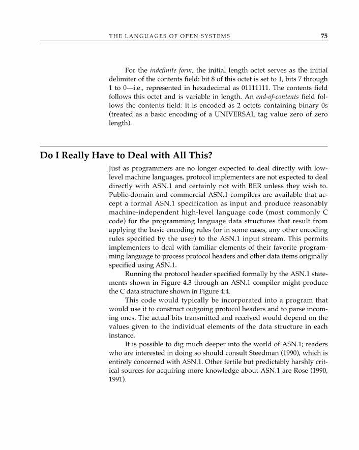
T H E L A N G U A G E S O F O P E N S Y S T E M S 75
For the indefinite form, the initial length octet serves as the initialdelimiter of the contents field: bit 8 of this octet is set to 1, bits 7 through1 to 0—i.e., represented in hexadecimal as 01111111. The contents fieldfollows this octet and is variable in length. An end-of-contents field fol-lows the contents field: it is encoded as 2 octets containing binary 0s(treated as a basic encoding of a UNIVERSAL tag value zero of zerolength).
Do I Really Have to Deal with All This?Just as programmers are no longer expected to deal directly with low-level machine languages, protocol implementers are not expected to dealdirectly with ASN.1 and certainly not with BER unless they wish to.Public-domain and commercial ASN.1 compilers are available that ac-cept a formal ASN.1 specification as input and produce reasonablymachine-independent high-level language code (most commonly Ccode) for the programming language data structures that result fromapplying the basic encoding rules (or in some cases, any other encodingrules specified by the user) to the ASN.1 input stream. This permitsimplementers to deal with familiar elements of their favorite program-ming language to process protocol headers and other data items originallyspecified using ASN.1.
Running the protocol header specified formally by the ASN.1 state-ments shown in Figure 4.3 through an ASN.1 compiler might producethe C data structure shown in Figure 4.4.
This code would typically be incorporated into a program thatwould use it to construct outgoing protocol headers and to parse incom-ing ones. The actual bits transmitted and received would depend on thevalues given to the individual elements of the data structure in eachinstance.
It is possible to dig much deeper into the world of ASN.1; readerswho are interested in doing so should consult Steedman (1990), which isentirely concerned with ASN.1. Other fertile but predictably harshly crit-ical sources for acquiring more knowledge about ASN.1 are Rose (1990,1991).
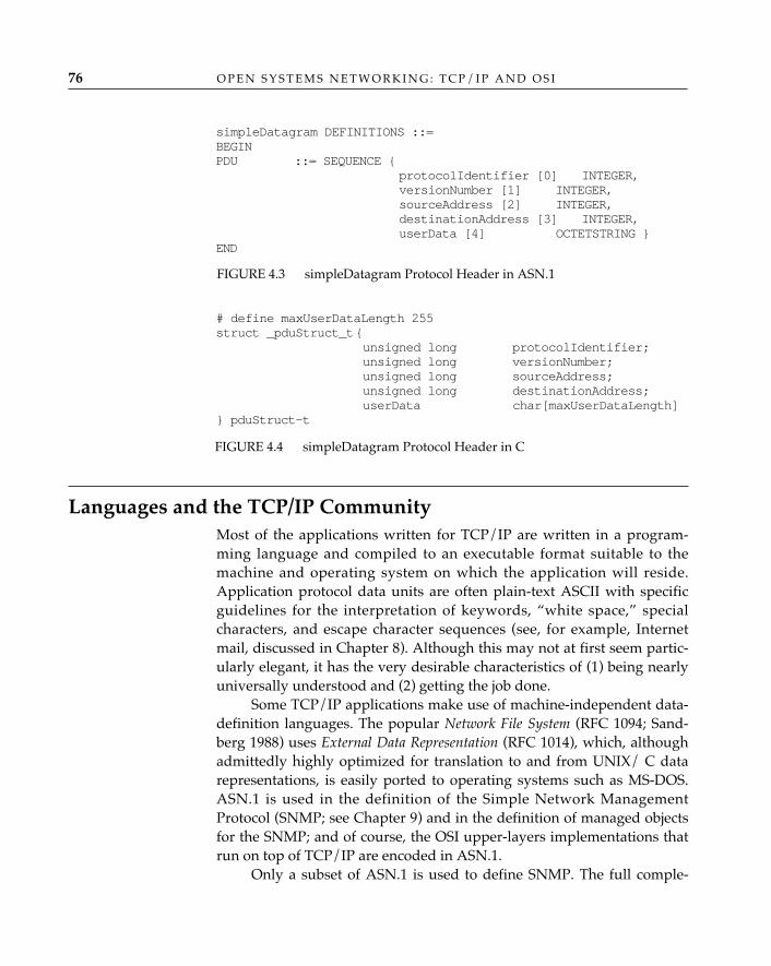
O P E N S Y S T E M S N E T W O R K I N G : T C P / I P A N D O S I76
Languages and the TCP/IP CommunityMost of the applications written for TCP/IP are written in a program-ming language and compiled to an executable format suitable to themachine and operating system on which the application will reside.Application protocol data units are often plain-text ASCII with specificguidelines for the interpretation of keywords, “white space,” specialcharacters, and escape character sequences (see, for example, Internetmail, discussed in Chapter 8). Although this may not at first seem partic-ularly elegant, it has the very desirable characteristics of (1) being nearlyuniversally understood and (2) getting the job done.
Some TCP/IP applications make use of machine-independent data-definition languages. The popular Network File System (RFC 1094; Sand-berg 1988) uses External Data Representation (RFC 1014), which, althoughadmittedly highly optimized for translation to and from UNIX/ C datarepresentations, is easily ported to operating systems such as MS-DOS.ASN.1 is used in the definition of the Simple Network ManagementProtocol (SNMP; see Chapter 9) and in the definition of managed objectsfor the SNMP; and of course, the OSI upper-layers implementations thatrun on top of TCP/IP are encoded in ASN.1.
Only a subset of ASN.1 is used to define SNMP. The full comple-
simpleDatagram DEFINITIONS ::=BEGINPDU ::= SEQUENCE {
protocolIdentifier [0] INTEGER, versionNumber [1] INTEGER,sourceAddress [2] INTEGER,destinationAddress [3] INTEGER,userData [4] OCTETSTRING }
END
FIGURE 4.3 simpleDatagram Protocol Header in ASN.1
# define maxUserDataLength 255struct _pduStruct_t{
unsigned long protocolIdentifier;unsigned long versionNumber;unsigned long sourceAddress;unsigned long destinationAddress;userData char[maxUserDataLength]
} pduStruct-t
FIGURE 4.4 simpleDatagram Protocol Header in C
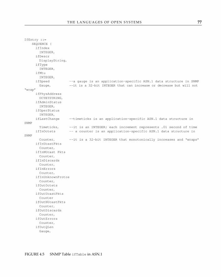
T H E L A N G U A G E S O F O P E N S Y S T E M S 77
IfEntry ::=SEQUENCE {ifIndexINTEGER,
ifDescrDisplayString,
ifTypeINTEGER,
ifMtuINTEGER,
ifSpeed --a gauge is an application-specific ASN.1 data structure in SNMPGauge, --it is a 32-bit INTEGER that can increase or decrease but will not
“wrap”ifPhysAddressOCTETSTRING,
ifAdminStatusINTEGER,
ifOperStatusINTEGER,
ifLastChange --timeticks is an application-specific ASN.1 data structure inSNMP
Timeticks, --it is an INTEGER; each increment represents .01 second of timeifInOctets -- a counter is an application-specific ASN.1 data structure in
SNMPCounter, --it is a 32-bit INTEGER that monotonically increases and “wraps”
ifInUcastPktsCounter,
ifInNUcast PktsCounter,
ifInDiscardsCounter,
ifInErrorsCounter,
ifInUnknownProtosCounter,
ifOutOctetsCounter,
ifOutUcastPktsCounter
ifOutNUcastPktsCounter,
ifOutDiscardsCounter,
ifOutErrorsCounter,
ifOutQLenGauge,
FIGURE 4.5 SNMP Table ifTable in ASN.1
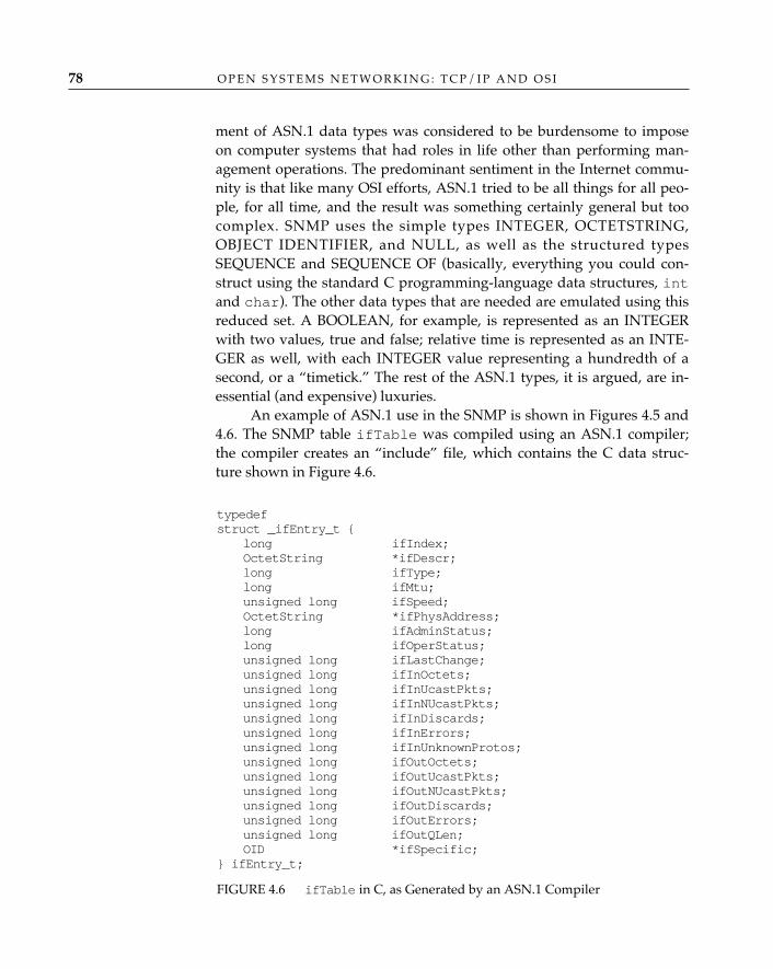
O P E N S Y S T E M S N E T W O R K I N G : T C P / I P A N D O S I78
ment of ASN.1 data types was considered to be burdensome to imposeon computer systems that had roles in life other than performing man-agement operations. The predominant sentiment in the Internet commu-nity is that like many OSI efforts, ASN.1 tried to be all things for all peo-ple, for all time, and the result was something certainly general but toocomplex. SNMP uses the simple types INTEGER, OCTETSTRING,OBJECT IDENTIFIER, and NULL, as well as the structured typesSEQUENCE and SEQUENCE OF (basically, everything you could con-struct using the standard C programming-language data structures, intand char). The other data types that are needed are emulated using thisreduced set. A BOOLEAN, for example, is represented as an INTEGERwith two values, true and false; relative time is represented as an INTE-GER as well, with each INTEGER value representing a hundredth of asecond, or a “timetick.” The rest of the ASN.1 types, it is argued, are in-essential (and expensive) luxuries.
An example of ASN.1 use in the SNMP is shown in Figures 4.5 and4.6. The SNMP table ifTable was compiled using an ASN.1 compiler;the compiler creates an “include” file, which contains the C data struc-ture shown in Figure 4.6.
typedefstruct _ifEntry_t {
long ifIndex;OctetString *ifDescr;long ifType;long ifMtu;unsigned long ifSpeed;OctetString *ifPhysAddress;long ifAdminStatus;long ifOperStatus;unsigned long ifLastChange;unsigned long ifInOctets;unsigned long ifInUcastPkts;unsigned long ifInNUcastPkts;unsigned long ifInDiscards;unsigned long ifInErrors;unsigned long ifInUnknownProtos;unsigned long ifOutOctets;unsigned long ifOutUcastPkts;unsigned long ifOutNUcastPkts;unsigned long ifOutDiscards;unsigned long ifOutErrors;unsigned long ifOutQLen;OID *ifSpecific;
} ifEntry_t;
FIGURE 4.6 ifTable in C, as Generated by an ASN.1 Compiler
T H E L A N G U A G E S O F O P E N S Y S T E M S 79
ConclusionThis chapter has described the formal way in which data are representedin OSI applications and the means by which not only the values of databut the semantics associated with them are transferred between distrib-uted applications. The authors have described only enough of ASN.1, thedata-definition language used in the development of OSI application ser-vices, to enable readers to understand some of the protocol examplesgiven in the text. Readers interested in the details and intricacies of ASN.1are encouraged to read Steedman (1990). This chapter has also describedthe way data are represented and manipulated by TCP/IP applicationsand how ASN.1 is applied in the Internet as well as the OSI community,but with an economy of data-type definitions (see also RFCs 1155, 1157,and 1213). And finally, the chapter has introduced the notion of objectidentification; in the following chapters, readers will appreciate theimportant role that object identifiers play in the open systems “namegame.”
5 NAMES AND ADDRESSES
John Schoch’s well-known differentiation of names, addresses, androutes (Schoch 1978) unintentionally spawned widespread misunder-standing of the role of naming in network architectures. It asserts thatnames and addresses are fundamentally different and that routes andaddresses are unrelated. In fact, anything that serves semantically toidentify is, by definition, a name. An address is simply a name with spe-cial properties: an address is also a name (of a point within a specifiedcoordinate system), but not all names are addresses. A route is not anidentifier at all, but a specification of a path from one point to another ina graph that represents the topology of a particular network at a particu-lar point in time.
To understand the role that they play in open systems networking,it is not important to recognize a high-level distinction between names ingeneral and the names of network locations (addresses). In this chapter,the discussion of “names” applies as well to the special class of namesthat are addresses. Routes, since they are not identifiers, are covered else-where (in Chapter 14). We also discuss the role of registration authoritiesin the administration of open system naming schemes and describe themost important classes of names and addresses (some of which are cov-ered, in much greater detail, in the chapters that describe the networkcomponents that actually use them).
81
O P E N S Y S T E M S N E T W O R K I N G : T C P / I P A N D O S I82
NamesThe importance of naming schemes should be intuitively obvious to any-one who has ever dealt with a large distributed system of any kind (suchas the postal mail system, a motor-vehicle registry, or a computer net-work). A naming scheme specifies the structure and significance ofnames and the way in which a name is allocated (selected from the set—the “name space”—of all possible names) and assigned (associated with,or “bound to,” the particular object for which it is the identifier).
A naming scheme may be characterized according to a number ofbasic criteria, including:
• Scope: whether a naming scheme is intended to apply globally to anentire class (or to entire classes) of objects or is intended to beunderstood only within and with respect to a particular local con-text
• User-friendliness: whether a name must be intelligible to and usableby a human user or is intended only for communication among“nonhuman” network elements
• Scale: the ability of a naming scheme to accommodate an increase inboth the number and (potentially) the internal complexity of namesas the size of the corresponding system increases
• Permanence: whether the binding of a name to an object is transient(and whether or not the name may be reassigned to another objectafter its association with one object has ended) or persistent (and ifthe latter, whether or not the name or some part of it must be regis-tered with a formal registration authority in order to ensure that itcan be used unambiguously throughout an open system)
The way in which a particular type of name will be used determinesthe importance of each of these criteria to the design of an appropriate nam-ing scheme. For example, a system of names for houses along a street(“street numbers”) will generally be designed for limited scope (the contextis provided by the street; different houses on different streets may have thesame street number without ambiguity); a high degree of user-friendliness(since human “users” will be writing these street numbers on envelopes;they should probably not, for example, start at 5,354,201 or some other largenumber); the ability to scale to at least the number of houses that might rea-sonably be built along the street, coupled with an assignment rule thatleaves enough space between adjacent house numbers to accommodate thefuture construction of new houses on side lots; and of course, permanence(for which the guarantor is often the town’s tax assessor).
The most straightforward way to keep track of the names that have beenallocated from a particular name space is simply to enumerate them in alist, in which each name appears once. If the number of names that havebeen allocated is “small enough,”1 this is also a perfectly practical way tokeep track of them and to advertise them if necessary (so as to make thenames, and their object bindings, known to potential users); but if thenumber grows too large, the cost of maintaining and distributing thesimple enumerated list of names eventually becomes excessive. How-ever, for a “flat” name space, from which names with no discerniblestructure are allocated, there is no alternative: every reference by nameto a set of objects must name every member of the set individually.
If the names associated with a particular name space do have a dis-cernible structure, however, they can be grouped accordingly. The struc-ture may be syntactic or semantic, or some combination. In the case ofstreet numbers, for example, it is common to allocate only odd numbersto houses along one side of the street and only even numbers to housesalong the other side, which creates a discrimination that is based on asemantic attribute of the house number. In order to make a statementabout the entire collection of houses on one side of the street, it is notnecessary to enumerate every house number; it is sufficient to refer to“the houses with odd [or “even,” as the case may be] house numbers.” Inlarge condominium complexes consisting of more than one building, it isalso common to name individual condominium units by means of a two-part identifier, the first part of which names the building and the secondpart of which names the unit within the building (such as “B-42” for unit42 in building B). The syntax of the name creates a discrimination thatallows the local fire department, for example, to determine which build-ing to train its hoses on without individually identifying all the unitscontained within that building (all of which, in the case of a building fire,share a common fate).
The second example illustrates the usefulness of hierarchy as a wayof structuring an address space. In a hierarchically structured namespace, individual names (and the objects to which they are bound) can beeffectively grouped into larger and larger aggregations based on someproperty of the objects that is reflected in a corresponding hierarchicalproperty of the name space. Such a structure, which is commonly repre-sented by an inverted tree diagram, makes it possible to refer to a collec-
N A M E S A N D A D D R E S S E S 83
Hierarchy
1. “Small enough” is, of course, a subjective measure; what is “small enough” for acomputer’s database-management system may be “too large” by far for a human adminis-trator with a clipboard.
tion of objects by giving just the name of the collection (the subset, or“subtree,” of the structure that contains all the objects that share a com-mon property of interest) rather than exhaustively naming the individualelements of the subset.
Although hierarchies are generally established according to criteriathat are related to some property of the named objects—their locationwithin a network, for example—they may also be established purely foradministrative convenience, without reference to any essential propertyof the named objects. It might be convenient, for example, to define ahierarchy within a hitherto flat name space in order to distribute the jobof allocating and assigning names among several managers, even thougha hierarchically structured name space does not confer any benefit withrespect to dealing with the named objects; in such a case, there is no prac-tical significance to the fact that the name of an object appears in one partof the hierarchy or another.
Occasionally, the desire to establish a hierarchical structure basedon the corresponding real-world organization of the named objects col-lides with an equally strong desire to establish a hierarchical structurebased on the administrative convenience of the registration authority orauthorities responsible for the task of managing the assignment ofnames. More often, however, there is a natural relationship between theway in which objects are organized (the practical hierarchy) and the wayin which their names are most readily managed (the administrative, ornaming, hierarchy).
The difficulty of managing a flat name space increases linearly withits size. The difficulty of managing a hierarchical name space can bemade to increase at a much slower rate by judicious selection of the hier-archy. As we will see in the chapters on the network layer (Chapter 13)and routing (Chapter 14), the selection of an appropriate hierarchy deter-mines whether or not a network architecture scales well—that is, whetherit supports a network that can continue to grow in size and extent or cre-ates practical upper bounds on size and extent that inhibit the network’sgrowth.
The OSI naming architecture is described in part 3 of the OSI referencemodel (ISO/IEC 7498-3: 1989), Naming and Addressing. In the layeredarchitecture of OSI, entities represent the active agents that operate withina layer to carry out its assigned functions (see Chapter 3); entities arenamed by entity titles, or simply titles. Service access points (SAPs) repre-sent the logical interfaces between adjacent layers, at which the lower-layer service is conceptually presented to and received by the upper layer.Service access points are named by service access point addresses.
O P E N S Y S T E M S N E T W O R K I N G : T C P / I P A N D O S I84
OSI NamingArchitecture
In principle, each of the seven layers of the OSI reference modelcontains named (“titled”) entities, and each of the six layer serviceboundaries (there is no application-layer service boundary) is speckledwith addressable service access points. In practice, however, the onlyimportant titles are those associated with entities in the application andnetwork layers: application entity titles (AE-titles), because they are thebasic unit of identification for OSI applications (the “end users” of an OSInetwork), and network entity titles (NETs), because routing informationis exchanged among network entities independent of any particular dataflow between network service access points. None of the other layerscontains entities that need to refer to each other independent of the ser-vice access points to which they provide access. The truly importantaddresses are the network, or network service access point (NSAP), ad-dress (which identifies individual hosts connected to the network), andthe subnetwork address (which identifies a point at which any system—host or router—is logically or physically attached to a real network).
Service access point addresses above the network layer are con-structed by simply concatenating a selector to the next-lower-layer serviceaccess point address. The selectors are used to accomplish a “fan-out” atthe layer service boundary to (potentially) multiple entities in the layerabove. The presentation address is the culmination of this process ofaddress composition—it identifies an application entity, which is as farup the stack as you can go in the OSI architecture. The presentationaddress is particularly significant as the point at which the names associ-ated with applications are coupled to the addresses that are used byOSI-defined services and protocols (see Chapters 7 and 11). Below thenetwork layer, the abstract concepts of “service access point” and “ser-vice access point address” bear only a forced and awkward relevance tothe technology-specific data link and physical components of real net-works and are best left unexplored.2
Since the ultimate sources and sinks of information in an OSI networkare application entities, every end-user interaction in an OSI environ-
N A M E S A N D A D D R E S S E S 85
2. This is an excellent example of the benefit of knowing what is and is not important!The ISO and CCITT committees concerned with data link–layer standards have spent end-less hours debating the existence and properties of data link addresses without coming toany satisfying conclusions that apply to the data link service in general (rather than to oneor more data link technologies in particular). This unproductive exercise has been pursuedbecause the groups involved failed to recognize a very basic point: that the concept of “ser-vice access point address” is not useful in the context of the data link service (notwith-standing the reference model mandate that all service boundaries have SAPs and all SAPshave addresses).
ApplicationEntity Titles
ment depends, at some point, on the identification of the participatingapplication entities by their application entity titles, and by implication,the presentation address associated with that title.
Prior to the development of the X.500-series standards for the OSIDirectory, the syntax of application entity titles was poorly defined.However, this caused very few problems because, in the absence of adirectory, the early end users of OSI were unlikely to make use of any ofthe application-layer features that would have required them to knowwhat an application entity title was. The ASN.1-encoded, generic form ofapplication entity title, contained in early drafts of the OSI standard forregistration authorities (ISO/IEC 9834-1: 1991), was both very simple andnot very useful:
AE-Title ::= SEQUENCE {AP-Title,AE-Qualifier }
The registration authority standard also defined an all-numeric formof application entity title, in which the application process title (AP-Title in the ASN.1 definition) part is syntactically an object identifier,and the application entity qualifier (AE-Qualifier) part is an integer:
AP-Title ::= IMPLICIT objectIdentifierAE-Qualifier ::= INTEGER
The agreements reached by ISO/IEC and CCITT on the 1988 (andsubsequent) directory standards (see Chapter 7) included the recognitionof two well-defined forms for the application entity title, one of which isthe object identifier form just shown. The other, much more useful, formis one in which the application entity title is syntactically equivalent to adirectory distinguished name:
AP-Title ::= RDNSequenceAE-Qualifier ::= RelativeDistinguishedName
A relative distinguished name sequence (RDNSequence) is just asequence of relative distinguished names of entries in the directory infor-mation tree; in this second form of application entity title, the applicationprocess title contains the relative distinguished names of the directoryentries from the root down to (but not including) the entry that repre-sents the application entity, and the application entity qualifier adds therelative distinguished name of the application entity entry itself. Thismakes it easy to list an application entity in the directory and to refer to itby a distinguished name that may be used as a valid title for the applica-tion entity.
O P E N S Y S T E M S N E T W O R K I N G : T C P / I P A N D O S I86
Recognizing that applications—even OSI applications—necessarilyreside in systems, and that people have become accustomed over theyears to thinking about applications as “running on” a particular com-puter system, the OSI naming scheme defines the concept of system title,the effect of which is to bring the decomposition of the application entitytitle, begun in the previous subsection, even closer to the real world.
The concept of system title is equivalent to the familiar concept ofhost name in TCP/IP; it is a permanent identifier for a particular OSI endsystem (host), and the identification of applications running on that endsystem can be based on it by further decomposing the application pro-cess title in either its object identifier form or its relative distinguishedname form:
Generic form:
AP-Title ::= SEQUENCE {System-Title,AP-Qualifier }
Form 1:
System-Title ::= RDNSequenceAP-Qualifier ::= RelativeDistinguishedName
Form 2:
System-Title ::= objectIdentifierAP-Qualifier ::= INTEGER
The entire process of application entity title formation can now betraced back to the registration of system titles, or host names. The distin-guished name form of an application entity title begins with a high-ordersequence of relative distinguished names registered (implicitly, as a sim-ple consequence of being entered in the directory information base, orexplicitly) by a system-title registration authority, to which another rela-tive distinguished name is concatenated to form an application processtitle, to which another relative distinguished name is concatenated toform an application entity title—et voilà! A similar process of concatena-tion of subidentifiers to a base system-title object identifier creates theobject identifier form of an application entity title.
By convention, registration authorities for system titles and appli-cation process titles require the simultaneous allocation of both forms(object identifier and relative distinguished name sequence), whichensures that the values of both forms are (1) interchangeably availablefor use (they appear, logically, in the same place in the register) and(2) protected from allocation as the value of any other title.
N A M E S A N D A D D R E S S E S 87
System Titles
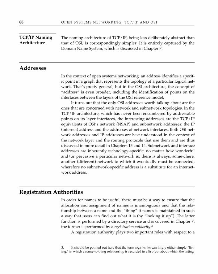
O P E N S Y S T E M S N E T W O R K I N G : T C P / I P A N D O S I88
The naming architecture of TCP/IP, being less deliberately abstract thanthat of OSI, is correspondingly simpler. It is entirely captured by theDomain Name System, which is discussed in Chapter 7.
AddressesIn the context of open systems networking, an address identifies a specif-ic point in a graph that represents the topology of a particular logical net-work. That’s pretty general, but in the OSI architecture, the concept of“address” is even broader, including the identification of points on theinterfaces between the layers of the OSI reference model.
It turns out that the only OSI addresses worth talking about are theones that are concerned with network and subnetwork topologies. In theTCP/IP architecture, which has never been encumbered by addressablepoints on its layer interfaces, the interesting addresses are the TCP/IPequivalents of OSI’s network (NSAP) and subnetwork addresses: the IP(internet) address and the addresses of network interfaces. Both OSI net-work addresses and IP addresses are best understood in the context ofthe network layer and the routing protocols that use them and are thusdiscussed in more detail in Chapters 13 and 14. Subnetwork and interfaceaddresses are inherently technology-specific: no matter how wonderfuland/or pervasive a particular network is, there is always, somewhere,another (different) network to which it eventually must be connected,wherefore no subnetwork-specific address is a substitute for an internet-work address.
Registration AuthoritiesIn order for names to be useful, there must be a way to ensure that theallocation and assignment of names is unambiguous and that the rela-tionship between a name and the “thing” it names is maintained in sucha way that users can find out what it is (by “looking it up”). The latterfunction is performed by a directory service and is covered in Chapter 7;the former is performed by a registration authority.3
A registration authority plays two important roles with respect to a
TCP/IP NamingArchitecture
3. It should be pointed out here that the term registration can imply either simple “list-ing,” in which a name-to-thing relationship is recorded in a list (but about which the listing
particular class of names: it administers the name space, managing theactual allocation of values from the name space and the assignment ofthose values to things that are entitled to be identified by a name of thatclass; and it maintains a record of the name-to-thing bindings that it hascreated. This record of bindings may then be incorporated into a directo-ry (see Chapter 7). It is important to recognize, however, that registrationand directories are separate systems (although in some cases, as we shallsee in our discussion of the Domain Name System in Chapter 7, they areinextricably linked). Registration may proceed whether or not there is adirectory in which the registered names are listed. A directory, however,implies at least an informal or implicit registration authority responsiblefor the names that appear in the directory.
In the OSI world, the way in which registration authorities operate isdefined by an international standard, ISO/IEC 9834-1: 1991, which is(intentionally) identical to CCITT Recommendation X.660. This standardspecifies a tree-structured name-registration hierarchy, within which in-dividual registration authorities operate, exercising hegemony over thatpart of the global name space that is represented by the subtree forwhich the authority is the root. The topmost levels of the registrationhierarchy are defined by ISO/IEC 8824 (CCITT X.208) and ISO/IEC9834-1 (CCITT X.660), which together specify the registration hierarchyshown in Figure 5.1.
In the world of open systems, there are a great many identifiertypes that must be registered in order to ensure that they can be usedunambiguously. In the OSI world, these include:
Document typesStandardized object identifiersVirtual Terminal profiles and control objects profilesAP titles and AE titlesAbstract syntaxes
N A M E S A N D A D D R E S S E S 89
agency makes no assertions of any kind), or ”formal registration,” in which the registeringagency not only records and lists a name-to-thing relationship but also confers “legitimacy”on it—guaranteeing, for instance, that the name is not bound to any other object or that theperson or organization registering the name has some legal right or entitlement that isexpressed by the fact that the name is registered with the agency. At this time, it is not clearwhich model of “registration” applies to the registration authorities that have been and arebeing formed in support of open systems networking. It is likely, however, that registrationauthorities established by international standards or, within countries, by national govern-ments or national standards organizations will operate in accordance with the “formal reg-istration” model but that the directory systems in which name-to-thing bindings are record-ed for others to “look up” will operate according to the “listing” model.
RegistrationAuthorityProcedures
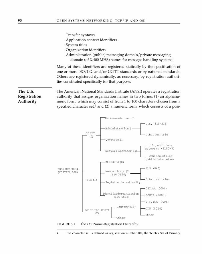
O P E N S Y S T E M S N E T W O R K I N G : T C P / I P A N D O S I90
Transfer syntaxesApplication context identifiersSystem titlesOrganization identifiersAdministration (public) messaging domain/private messaging
domain (of X.400 MHS) names for message handling systems
Many of these identifiers are registered statically by the specification ofone or more ISO/IEC and/or CCITT standards or by national standards.Others are registered dynamically, as necessary, by registration authori-ties constituted specifically for that purpose.
The American National Standards Institute (ANSI) operates a registrationauthority that assigns organization names in two forms: (1) an alphanu-meric form, which may consist of from 1 to 100 characters chosen from aspecified character set,4 and (2) a numeric form, which consists of a posi-
FIGURE 5.1 The OSI Name-Registration Hierarchy
Recommendation (0
U.S. (840)
Network operator (3)
Question (1
Administration (2
Identified organization (ISO 6523)
Member body (2(ISO 3166)
Registration authority
Standard (0)
Country (16)
Other
Joint ISO-CCITT(2)
ISO (1)
CCITT(0)
ISO/IEC 9834-(CCITT X.660)
U.S. (310–316)
Other countries
U.S. public datanetworks (3100–31
Other countries’public data networ
Other countries
OIW (0014)
GOSIP (0005)
OSInet (0004)
U.S. DOD (0006)
Other
The U.S.RegistrationAuthority
4. The character set is defined as registration number 102, the Teletex Set of Primary
tive decimal integer greater than or equal to 113,527 and less than 16 mil-lion. The numeric form may be obtained with or without a correspondingalphanumeric form, but the alphanumeric form is always accompaniedby (and in the register, associated with) a numeric form.
Many people have wondered why ANSI decided to begin theassignment of numeric organization names at the nonintuitive
value “113,527,” which is not, among other things, a power of 2 (or any otherinteresting number). Realizing that they had to specify some value as the start-ing point (and hoping to avoid conferring any special cachet on the recipients ofthe first few numbers by starting at, say, “1”), the members of the U.S. registra-tion authority committee were about to pick a “logical” number (“1,000,” per-haps, or “2,048”) when Jack Veenstra, the chairman of the committee, shouted“113,527!”—which was promptly dubbed the “Veenstra constant” and writteninto the registration authority procedures. Later, the members of the committeearranged for AT&T (Veenstra’s employer) to receive the numeric organizationname “113,527” in Jack’s honor.
An organization name may be used in several different ways toform unambiguous identifiers. The alphanumeric form is most oftenused as the organization name in an electronic-mail address (as, forexample, the value of the “organization” or “organizational unit” ele-ments of an X.400 originator/recipient address containing “/C = US”; seeChapter 8). The numeric form may be used as the value of the “organiza-tion” field in an OSI NSAP address constructed according to ANSIStandard X3.216-1992 (see Chapter 13) or as part of an object identifierprefix for constructing unambiguous object identifiers for organization-specific objects (such as, for example, organization-specific managementinformation base variables for use with a network management system).The registration authority does not specify or constrain the way in whichan organization name may be used, nor does it guarantee the legal rightof an organization to actually use the name. Only one guarantee comeswith an organization name obtained from ANSI’s registration authority:that ANSI has not previously assigned the same name to anyone elseand will not do so in the future.
Until recently, the U.S. name-registration authority conducted itsbusiness under the { iso (1) member-body (2) us (840) } arcof the registration hierarchy (see Figure 5.1), registering names for ANSI
✧AHA✧
N A M E S A N D A D D R E S S E S 91
Graphic Characters, of the ISO International Register of Character Sets to Be Used withEscape Sequences, plus the space character.
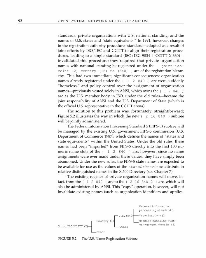
O P E N S Y S T E M S N E T W O R K I N G : T C P / I P A N D O S I92
standards, private organizations with U.S. national standing, and thenames of U.S. states and “state equivalents.” In 1991, however, changesin the registration authority procedures standard—adopted as a result ofjoint efforts by ISO/IEC and CCITT to align their registration proce-dures, leading to a single standard (ISO/IEC 9834 | CCITT X.660)—invalidated this procedure; they required that private organizationnames with national standing be registered under the { joint-iso-ccitt (2) country (16) us (840) } arc of the registration hierar-chy. This had two immediate, significant consequences: organizationnames already registered under the { 1 2 840 } arc were suddenly“homeless,” and policy control over the assignment of organizationnames—previously vested solely in ANSI, which owns the { 1 2 840 }arc as the U.S. member body in ISO, under the old rules—became thejoint responsibility of ANSI and the U.S. Department of State (which isthe official U.S. representative in the CCITT arena).
The solution to this problem was, fortunately, straightforward;Figure 5.2 illustrates the way in which the new { 2 16 840 } subtreewill be jointly administered.
The Federal Information Processing Standard 5 (FIPS-5) subtree willbe managed by the existing U.S. government FIPS-5 commission (U.S.Department of Commerce 1987), which defines the names of “states andstate equivalents” within the United States. Under the old rules, thesenames had been “imported” from FIPS-5 directly into the first 100 nu-meric name slots of the { 1 2 840 } arc; however, since no nameassignments were ever made under these values, they have simply beenabandoned. Under the new rules, the FIPS-5 state names are expected tobe available for use as the values of the stateOrProvince attribute inrelative distinguished names in the X.500 Directory (see Chapter 7).
The existing register of private organization names will move, in-tact, from the { 1 2 840 } arc to the { 2 16 840 2 } arc, which willalso be administered by ANSI. This “copy” operation, however, will notinvalidate existing names (such as organization identifiers and applica-
FIGURE 5.2 The U.S. Name-Registration Subtree
Joint ISO/CCITT (2)
Other
Country (16
U.S. (840
Other
Federal informationprocessing standard 5 (
Organizations (2)
Message handling systemanagement domain (3)
N A M E S A N D A D D R E S S E S 93
tion entity titles) that may already have been constructed using the { 12 840 } prefix; in effect, two equivalent prefixes will exist (in perpetu-ity) for currently registered organization names. New registrations willbe made only under the new { 2 16 840 2 } arc, and organizationspossessed of an “old” registration will be encouraged (but not required)to construct no new identifiers under the { 1 2 840 } arc but to usethe { 2 16 840 2 } arc instead.
The numeric organization names under { 2 16 840 2 } will beused as values of the “organization” field in the construction of NSAPaddresses with authority and format identifier values of 38 or 39 and aninitial domain identifier value of 840, according to American NationalStandard X3.210-1992, just as they were under the old rules (see Chapter13); this usage is not affected by the switch to a new subtree, since onlythe numeric organization name, without the qualifying { 1 2 840 } or{ 2 16 840 2 } prefix, is used in the construction of NSAP addresses.
Since the rule change covers only “private organization names withnational standing,” the existing mechanism for registering the names ofAmerican national standards under the { 1 2 840 } arc is unaffectedand will remain in place.
The creation of a new arc for message handling system manage-ment domain names recognizes the apparently unreconcilable differencebetween the general registration of organization names and the registra-tion of names that will be used as administration messaging domain andprivate messaging domain names for X.400 (see Chapter 8). This isunfortunate, since it means that organization names registered under theorganizations arc—including those names that have already been regis-tered under the “old rules”—cannot be used as administration messag-ing domain or private messaging domain names in an X.400 originator/recipient address unless they are also registered under the new messagehandling system management domain arc. The very different require-ments associated with the registration of organization names that areintended for use in an X.400 context make this situation unavoidable.
The designers of the original registration authority for theUnited States recognized that their general-purpose registry,
which permitted great flexibility in the formation of an acceptable organizationname (it could consist of up to 100 characters chosen from a very large characterset), could not enforce the constraints that might be applicable to the use forwhich a registered name was intended. Message handling system managementdomain names, for example, are constrained by CCITT Recommendation X.411to be no longer than 16 bytes and must be constructed from the “Printable-
✧AHA✧
String” character set defined by ISO/IEC 8824. They hoped, however, that theseadditional constraints could be observed in practice without creating applica-tion-specific registries for different types of organization name. The difficulties ofdoing so, at least in the case of organization names that will be used as MHSadministration or private domain names, have proved to be too great.
The United States is not, of course, the only country with a need to regis-ter names with national standing under the various arcs of the ISO/IEC9834 registration hierarchy. ANSI’s counterpart in the United Kingdom,the British Standards Institute, operates a similar U.K. Registration Au-thority (UKRA),5 which is governed by British Standard (BS) 7306 (1990).The U.K. registration authority is more specific than ANSI’s; whereasANSI hands out organization names that can be used for a wide varietyof purposes, BSI has elected to assign organization names that can onlybe used in the construction of OSI network-layer addresses (see Chapter13) and in fact the UKRA (see Chapter 13) includes the following specificdisclaimer: “Users of an X.400 service therefore obtain their O/R ad-dresses through mechanisms provided for that purpose, independentlyof any allocations that may be made under this standard.”
In the United States, ANSI operates the U.S. registration authority (inconjunction with the Department of State with respect to some of the arcsbelow { 2 16 840 }; see the subsection entitled “The U.S. RegistrationAuthority,” earlier in the chapter), but it is not the only organization regis-tering “national standing” identifiers. The U.S. General Services Admin-istration, acting for the National Institute of Standards and Technology(NIST), administers a GOSIP registration authority that assigns identi-fiers for use in two specific contexts:
1. GSA will provide U.S. government agencies with strings (all of whichbegin with the characters “GOV+”) that can be used in X.400 mailaddresses as part of constructed private management domain or orga-nization names, under a delegation from ANSI to NIST that is regis-tered as the arc { iso (1) member-body (2) us (840) gov (101) }.
2. GSA will provide, to anyone who asks, a numeric value that can beused in the administrative authority identifier field of U.S. GOSIPversion 2 NSAP addresses (see Chapter 13), under a delegation ofauthority from the ISO 6523 part of ISO’s subtree that is registered asthe arc { iso (1) identified-organization (3) NIST (5) }.
O P E N S Y S T E M S N E T W O R K I N G : T C P / I P A N D O S I94
The U.K.RegistrationAuthority
5. In fact, BSI has delegated the responsibility for actually operating the U.K.Registration Authority to the Electronics and Business Equipment Association.
The GOSIPRegistrationAuthority
Fortunately, these identifiers are in every case readily distinguish-able, in context, from identifiers registered with ANSI under other arcsof the registration hierarchy. ANSI has agreed not to allocate messagehandling system management domain names beginning with “GOV+”under its { 2 16 840 3 } arc, and the administrative authority identi-fier values allocated by GSA, although they are semantically equivalentto the organization field values allocated by ANSI, can appear only inNSAP addresses that follow the GOSIP version 2 format (with AFI = 47and IDI = 0005), whereas the org values can appear only in NSAPaddresses that follow ANSI Standard X3.216-1992.
In the Internet world, the list of names that are formally registered is(remarkably) even longer than it is for OSI. The Internet AssignedNumbers Authority (IANA) is responsible for assigning and registeringnames (which, in Internet jargon, are simply called “numbers,” sincethat’s what they are) of the following types:
Version numbersProtocol numbersPort numbersInternet multicast addressesThe Internet Ethernet address blockIP type-of-service parameter valuesIP time-to-live parameter valuesDomain Name System parameter valuesBOOTP parameter valuesNetwork management parameter valuesARPANET and MILNET logical addressesARPANET and MILNET link numbers and X.25 address mappingsIEEE 802 numbers of interestXNS protocol typesPRONET 80 type numbersEthernet numbers of interestEthernet vendor address componentsUNIX port numbersAddress resolution protocol parametersReverse address resolution protocol parametersDynamic reverse address resolution protocol parametersX.25 type numbersPublic data network numbersTELNET options
N A M E S A N D A D D R E S S E S 95
The InternetAssignedNumbersAuthority
O P E N S Y S T E M S N E T W O R K I N G : T C P / I P A N D O S I96
Mail encryption typesMachine namesSystem namesProtocol and service namesTerminal type names
These number registrations are published periodically in an Inter-net RFC entitled Assigned Numbers.
The preceding list does not include the most visible Internet regis-tration activity: the Internet registry, which assigns Internet networknumbers (the high-order part of a 32-bit Internet address, from whichindividual IP host numbers are generated). This activity is formally theresponsibility of the Internet Assigned Numbers Authority, but the actu-al assignment task has traditionally been carried out by the Internet’sNetwork Information Center (NIC). The Network Information Centerwas operated for many years by SRI International in Menlo Park, Cali-fornia, but was recently reassigned to Network Solutions, Inc., operatingunder contract to Government Systems, Inc. (GSI), operating under con-tract to the Defense Information Systems Agency (DISA, which was for-merly the Defense Communications Agency, or DCA).6 In most cases, apublic or commercial network operator (service provider) will apply tothe Internet registry for network numbers on behalf of its clients; in somecases, the registry preallocates blocks of numbers to a service provider,which is then free to further assign them to its clients as needed.
Object IdentifiersOf the data types predefined by the Abstract Syntax Notation One(ASN.1) standard (see Chapter 4), one—the OBJECT IDENTIFIER datatype—is particularly important to naming in OSI. The value of an objectidentifier names an information object; it is an ordered set of non-negative integer values whose root is defined in ISO/IEC 9834-1 andwhose branches or arcs are derived from the registration authoritiesdescribed earlier and depicted in Figure 5.2.
What are information objects? Applications and systems are objects.The documents that define OSI protocols and services are objects. OSIDirectory entries and attributes of those entries (see Chapter 7); X.400
6. If you followed all that, you might be qualified for a career in Internet name assign-ment; see Appendix D for the address and phone number of the Internet Network Inform-ation Center.
N A M E S A N D A D D R E S S E S 97
Message Handling System mail addresses (see Chapter 8); and the sets ofcounters, gauges, and status indicators used in the management of net-work resources by OSI’s Common Management Information Service andTCP/IP’s Simple Network Management Protocol (see Chapter 9) areamong the many things OSI considers objects. Essentially, anything in anetwork can be modeled as an object; among these, objects that require aname for unique and unambiguous identification are registered by anaming authority.
ConclusionThis chapter has described the roles names play in OSI and the formalcomposition of OSI addresses. (The roles of names in TCP/IP have inten-tionally been deferred to Chapter 7, where the Domain Name System isdiscussed, and the details of network addresses have been deferred toChapter 13, where OSI network service access point addresses and IPaddresses are discussed.) The names most relevant to understandinghow OSI applications identify each other for the purpose of conductinginformation exchange have been specified as well. The authors have alsoexplained that the means by which identifiers in general are guaranteeduniqueness is through the establishment of registration authorities recog-nized by ISO/CCITT and that a similar infrastructure exists for TCP/IP—i.e., the Internet Assigned Numbers Authority. The chapter concludedwith a discussion of the role played by object identifiers in the “namegame” and the relationship of this ASN.1 data type to name registration.

PA R T T H R E E
UPPER LAYERS
6 OPEN SYSTEMS APPLICATIONS
An architectural characteristic of open system networks (as opposed toproprietary networks) is the assumption of a set of generic, or generallyavailable, applications that serve as building blocks or “tools” for con-structing more complex distributed system applications. These are gener-ally regarded as “applications” in the TCP/IP world; in OSI, they arecalled distributed application services.
Distributed application services, whether OSI- or TCP/IP-based,share some characteristics in common. For example, irrespective ofwhether one describes a file transfer application that uses TCP/IP’s FileTransfer Protocol (FTP) or OSI’s File Transfer, Access, and Management(FTAM), the file transfer application will have at least the followingcharacteristics:
• An end-user interface that provides a human or another applicationwith the means to enter commands that direct the application tosend files to and receive files from a remote host, list or changedirectories, rename or delete files, move files from one directory toanother, etc. (There will also be a means for the application toinform the end user of the results of the actions, successful orfailed.)
• The means of performing input to and output from mass storagedevice(s) (disk-tape).
• The means of transferring the files and file-related informationbetween hosts.
Thus, for both OSI and TCP/IP, there are local and communica-tions components to every distributed or end-user application. The local
101
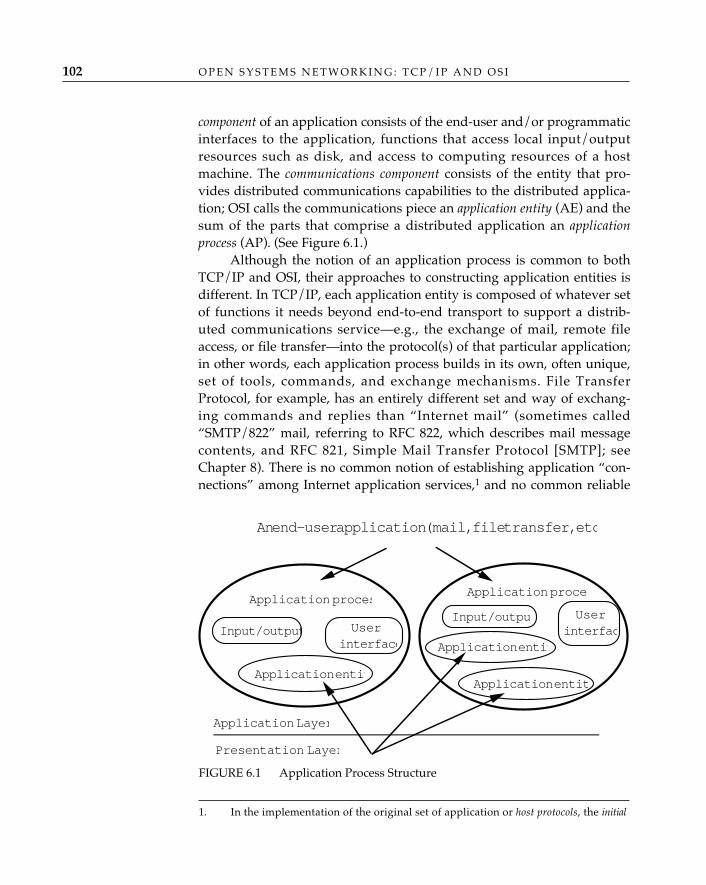
O P E N S Y S T E M S N E T W O R K I N G : T C P / I P A N D O S I102
component of an application consists of the end-user and/or programmaticinterfaces to the application, functions that access local input/outputresources such as disk, and access to computing resources of a hostmachine. The communications component consists of the entity that pro-vides distributed communications capabilities to the distributed applica-tion; OSI calls the communications piece an application entity (AE) and thesum of the parts that comprise a distributed application an applicationprocess (AP). (See Figure 6.1.)
Although the notion of an application process is common to bothTCP/IP and OSI, their approaches to constructing application entities isdifferent. In TCP/IP, each application entity is composed of whatever setof functions it needs beyond end-to-end transport to support a distrib-uted communications service—e.g., the exchange of mail, remote fileaccess, or file transfer—into the protocol(s) of that particular application;in other words, each application process builds in its own, often unique,set of tools, commands, and exchange mechanisms. File TransferProtocol, for example, has an entirely different set and way of exchang-ing commands and replies than “Internet mail” (sometimes called“SMTP/822” mail, referring to RFC 822, which describes mail messagecontents, and RFC 821, Simple Mail Transfer Protocol [SMTP]; seeChapter 8). There is no common notion of establishing application “con-nections” among Internet application services,1 and no common reliable
Application Layer
Presentation Layer
Application entit
Input/output
Application proces
An end-user application (mail, file transfer, etc
Application proce
Input/outpu
Application entit
Application entit
Userinterface
Userinterfac
FIGURE 6.1 Application Process Structure
1. In the implementation of the original set of application or host protocols, the initial
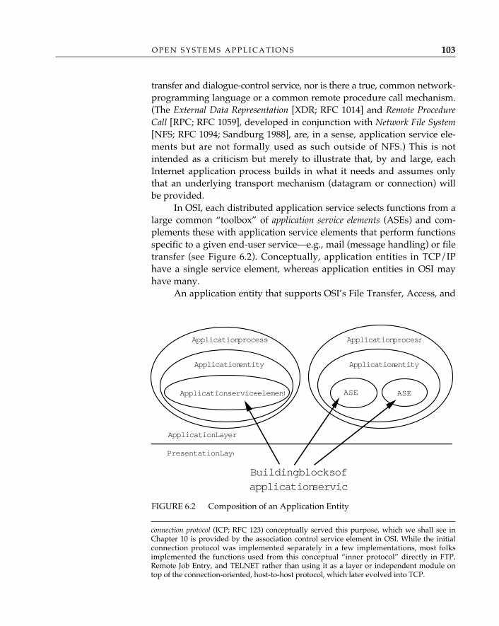
O P E N S Y S T E M S A P P L I C A T I O N S 103
transfer and dialogue-control service, nor is there a true, common network-programming language or a common remote procedure call mechanism.(The External Data Representation [XDR; RFC 1014] and Remote ProcedureCall [RPC; RFC 1059], developed in conjunction with Network File System[NFS; RFC 1094; Sandburg 1988], are, in a sense, application service ele-ments but are not formally used as such outside of NFS.) This is notintended as a criticism but merely to illustrate that, by and large, eachInternet application process builds in what it needs and assumes onlythat an underlying transport mechanism (datagram or connection) willbe provided.
In OSI, each distributed application service selects functions from alarge common “toolbox” of application service elements (ASEs) and com-plements these with application service elements that perform functionsspecific to a given end-user service—e.g., mail (message handling) or filetransfer (see Figure 6.2). Conceptually, application entities in TCP/IPhave a single service element, whereas application entities in OSI mayhave many.
An application entity that supports OSI’s File Transfer, Access, and
connection protocol (ICP; RFC 123) conceptually served this purpose, which we shall see inChapter 10 is provided by the association control service element in OSI. While the initialconnection protocol was implemented separately in a few implementations, most folksimplemented the functions used from this conceptual “inner protocol” directly in FTP,Remote Job Entry, and TELNET rather than using it as a layer or independent module ontop of the connection-oriented, host-to-host protocol, which later evolved into TCP.
FIGURE 6.2 Composition of an Application Entity
Application Layer
Application entity
Presentation Laye
Application process
Application entity
Application process
Application service element ASE ASE
Building blocks ofapplication servic
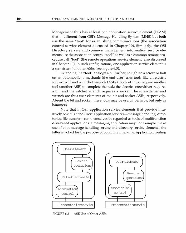
O P E N S Y S T E M S N E T W O R K I N G : T C P / I P A N D O S I104
Management thus has at least one application service element (FTAM)that is different from OSI’s Message Handling System (MHS) but bothuse the same “tool” for establishing communications (the associationcontrol service element discussed in Chapter 10). Similarly, the OSIDirectory service and common management information service ele-ments use the association-control “tool” as well as a common remote pro-cedure call “tool” (the remote operations service element, also discussedin Chapter 10). In such configurations, one application service element isa user element of other ASEs (see Figure 6.3).
Extending the “tool” analogy a bit further, to tighten a screw or bolton an automobile, a mechanic (the end user) uses tools like an electricscrewdriver and a ratchet wrench (ASEs); both of these require anothertool (another ASE) to complete the task: the electric screwdriver requiresa bit, and the ratchet wrench requires a socket. The screwdriver andwrench are thus user elements of the bit and socket ASEs, respectively.Absent the bit and socket, these tools may be useful, perhaps, but only ashammers.
Note that in OSI, application service elements that provide intu-itively obvious “end-user” application services—message handling, direc-tories, file transfer—can themselves be regarded as tools of multifunctiondistributed applications; a messaging application may, for example, makeuse of both message handling service and directory service elements, thelatter invoked for the purpose of obtaining inter–mail application routing
FIGURE 6.3 ASE Use of Other ASEs
Reliable transfer
User element
Remoteoperations
Associationcontrol
Presentation service Presentation service
User element
Remoteoperations
Associationcontrol
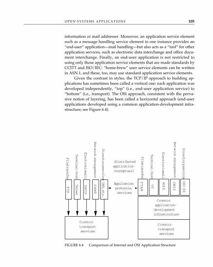
O P E N S Y S T E M S A P P L I C A T I O N S 105
information or mail addresser. Moreover, an application service elementsuch as a message handling service element in one instance provides an“end-user” application—mail handling—but also acts as a “tool” for otherapplication services, such as electronic data interchange and office docu-ment interchange. Finally, an end-user application is not restricted tousing only those application service elements that are made standards byCCITT and ISO/IEC: “home-brew” user service elements can be writtenin ASN.1, and these, too, may use standard application service elements.
Given the contrast in styles, the TCP/IP approach to building ap-plications has sometimes been called a vertical one: each application wasdeveloped independently, “top” (i.e., end-user application service) to“bottom” (i.e., transport). The OSI approach, consistent with the perva-sive notion of layering, has been called a horizontal approach (end-userapplications developed using a common application-development infra-structure; see Figure 6.4).
FIGURE 6.4 Comparison of Internet and OSI Application Structure
— etc. —
FTP
File transfer
Applicationprotocols,services
File transfer
Terminal-host
Terminal-host
Electronic mail
Electronic mail
Network management
Network management
Directory services
Directory services
DNS, etc.
SNMP
SMTP
Telnet
FTAM
VT
MHS
CMIP
OSI DS
(Distributedapplication—conceptual)
Commontransportservices
Commontransportservices
Commonapplication-developmentinfrastructure
O P E N S Y S T E M S N E T W O R K I N G : T C P / I P A N D O S I106
Distributed Application ServicesOSI is clearly not the exclusive distributed applications environment forall forms of distributed applications services. Applications developedover TCP/IP and other protocol suites tending toward “openness” satis-fy many essential end-user needs and are likely to continue to satisfythese needs along with OSI. This diversity is not a truly bad thing (seeChapter 17), since, historically, diversity and competition have often ledto improvements and landmark developments in computer communica-tions. It is also important to note that the applications-development infra-structure of OSI—the upper layers—may easily be ported over to existingtransport service infrastructures; this is especially true for TCP/IP, andthe success of enterprises of this sort is discussed in subsequent chapters.
The generality and flexibility of the OSI applications-develop-ment infrastructure is not without cost, and detractors continue
to berate it, criticizing it for its complexity (in both specification and implemen-tation) as well as the excessive processing and memory overhead that is associ-ated with operating distributed applications in this environment. Some of thiscriticism must be tempered by the fact that many of the existing implementa-tions are “first-generation,” and it is to be expected that further field and imple-mentation experience will yield leaner, faster software. Some of the criticism iswell-founded, and one can only hope that those who have implemented OSI-based applications will work to see that the standards are revised to correct majorshortcomings. Despite the criticism, OSI continues to be a catalyst for the devel-opment of protocol and service frameworks for interesting distributed services.
OSI’s applications-development infrastructure provides a convenientand multipurpose framework for the development of a wide range of dis-tributed applications; a sampling of these is described briefly in the follow-ing subsections. Some are variations on a familiar “theme”—electronic mail,file transfer, directories—whereas others are more forward-looking.
Electronic Mail and Message Handling System (MHS)—“E-mail” is theability to send and receive the electronic equivalent of written correspon-dence typically delivered through a postal agency. In addition to simpletextual mail messages, OSI message-handling services facilitate the elec-tronic exchange of documents that, in principal, can be comprised of fac-simile, graphics, or even speech or video. OSI’s Message Handling Systemis also likely to provide a distribution platform for office and electronicdocument exchange.
✧AHA✧
O P E N S Y S T E M S A P P L I C A T I O N S 107
Electronic Data Interchange (EDI)—The ability to exchange businessdocuments—e.g., standard “forms,” such as invoices, purchase orders,payment orders, and customs declarations/reports—is an internationalconcern, especially for the European Economic Community. OSI stan-dards for these forms are consistent with the United Nations/EDIFACTStandard, and the forms can be transferred using OSI’s Message Hand-ling System (see Chapter 8).
Office Document Architecture/Interchange (ODA/ODIF)—The abilityto exchange documents containing text and graphics—spreadsheets,page layouts from desktop-publishing applications, papers producedusing word-processing applications—between like and dissimilar appli-cations (e.g., from brand X word processor to brand Y) without losingany of the document’s contents is accommodated within OSI’s officedocument architecture, also known as the CCITT T.400-series Recom-mendations for document Transfer, Access, and Manipulation (DTAM).The office document architecture specifies document structures, inter-change formats, character content architectures, and content architec-tures for raster, tile raster, and geometric graphics (ISO/IEC 8613: 1989),in many parts).
Directory Services—Like the operator-assisted directory services offeredthrough the telephone network, this service includes the ability to matchnames with addressing information. In addition, OSI offers a compre-hensive registration and identification infrastructure that helps individuals,applications, and organizations acquire information (“attributes”) thatprovides a more detailed characterization of things (“objects”) that arenamed. The OSI Directory is expected to serve as a repository for infor-mation that characterizes people, applications, mail systems, manage-ment systems—virtually any information that one wishes to register andmake publicly available.
Distributed File Systems—The ability to access and manage file systemsmounted on remote computers is an integral part of distributed process-ing today. OSI offers new tools in this area and also an equivalent envi-ronment upon which to run existing and eminently popular tools such asNetwork File System.
Network Management—Network management provides the ability tomonitor the status and use of resources of a distributed processing envi-ronment—hosts, bridges, routers, the transmission facilities that inter-connect them, and software (application as well as protocol processes)resident on these machines—as well as the ability to detect, isolate, and
O P E N S Y S T E M S N E T W O R K I N G : T C P / I P A N D O S I108
circumvent problems that might arise in any of these network compo-nents. OSI has a comprehensive “common management” applicationsinfrastructure that provides monitoring, analysis, accounting, and diag-nostic services and more.
Remote Database Access—OSI provides a generic remote database arch-itecture—protocols and services—for client/server interactions (dialogue,transaction, and data-resource management) and also provides for a setof “specializations” that allow one to further define the parameters ofremote database access operations to accommodate a specific remotedatabase language—e.g., the standard query language SQL (ISO/IEC9579: 1992).
These are but a few of the areas of distributed processing and infor-mation technology that can use OSI. Of course, many of the capabilitiesOSI offers have easily identifiable TCP/IP counterparts. Applicationsbased on the Simple Mail Transfer Protocol (see Chapter 8) offer textualelectronic-mail correspondence similar to that offered via OSI’s MessageHandling System and, with recent extensions that are today experimen-tal, may enable multimedia messaging as well. The Domain Name Systemoffers a host name– to–IP address service similar to an application-name–to–presentation-address capability offered by the OSI Directory;other Internet applications—such as WHOIS, FINGER, Archie, the WideArea Information Service, and the WorldWideWeb—offer a variety of re-source locators and information services (see Chapter 7).
In certain application areas—messaging and directory services—many believe that OSI adds value to existing TCP/IP applications. Inother areas—for example, distributed file services and window-basedsystems—existing services like NFS are considered superior to applica-tion services developed specifically for OSI. In fact, the utility and wide-spread application of services such as NFS and the X Window Systemhave provided the basis for the development of conventions and eventu-ally standards for operating these applications over OSI stacks.
This is true in the area of network management as well. Althoughthere are those who believe that OSI’s “common management” is superiorin many ways to the Simple Network Management Protocol, applicationsbased on the SNMP are sufficiently popular that they are now used to man-age dual-stack (OSI and TCP/IP) internets (actually, the Simple NetworkManagement Protocol framework provides network management for large-scale internets that are IP- as well as XNS/IPX, AppleTalk-, and OSI-based).And recent extensions to the Simple Network Management Protocolarguably improve on an already useful and proven commodity.
O P E N S Y S T E M S A P P L I C A T I O N S 109
There are also areas where OSI will offer application services thatare to date not addressed in TCP/IP: OSI’s progress on transaction pro-cessing, office document architecture, and electronic data interchangestandards is followed with great interest by the Internet community.
ConclusionThis chapter has described how OSI and TCP/IP differ significantly intheir approaches to constructing distributed system applications. OSIasserts that distributed applications operate over a strict hierarchy of layersand are constructed from a common tool kit of standardized applicationservice elements; TCP/IP makes no such assertion, insisting only thatdistributed applications operate over a common end-to-end transportservice. Which approach is better? OSI’s is general and flexible, and itsemphasis on modularity and reuse of common mechanisms comportswell with current object-oriented models of application development;but generality costs, and as is the case with many aspects of OSI, the inef-ficiency of a too-literal implementation may outweigh the theoreticalbenefits. TCP/IP’s “apply to affected area as needed” approach is moreapplication-specific and may lead to the redundant implementation ofthe same function in many different applications; but in most cases, thegreater efficiency and performance of the resulting applications out-weigh the potentially greater inefficiency of application software devel-opment. It is interesting to observe that the most promising new work onthe implementation of the “upper layers” of OSI (see Chapter 11) com-bines the functions of the application, presentation, and session layersinto a common library of modules that are included—or not included—in applications, as each demands. This is yet another example of OSI’slearning and borrowing from TCP/IP—an exchange that takes place inboth directions much more readily (and frequently) than most peoplesuspect (or are willing to admit).
The remaining chapters in Part Three examine application servicesand upper layers in a “top-down” fashion. Although this may seem con-trary to the customary flow, a top-down approach has the advantage ofallowing readers to deal first with easily recognizable and practicalexamples of services encountered on a daily basis—the use of a tele-phone, a postal service, a telephone book, or directory assistance—andgradually learn the technical aspects of how equivalent “electronic” ser-vices are provided across complex internets. Thus, Part Three continues
O P E N S Y S T E M S N E T W O R K I N G : T C P / I P A N D O S I110
by providing a comparison of application services offered by both archi-tectures, focusing on function and high-level operation. Chapters 7, 8,and 9 examine three distributed application services—directories, elec-tronic messaging, and network management. These are chosen becausethey are popular and easily recognized distributed applications andbecause there is considerable overlap between the OSI and TCP/IP coun-terparts with respect to services offered. From this sampling, readers areexpected to gain an overall understanding of distributed processing inOSI and TCP/IP.
Chapter 10 examines three application service elements—associa-tion control, remote operations, and reliable transfer—that provideessential, or “core,” services for distributed applications in OSI, andChapter 11 describes the OSI presentation and session layers. A conse-quence of the rigid layering in the OSI upper layers is that many of thefunctions that an application may use or invoke are accessed throughapplication service elements but performed elsewhere in the architecture(e.g., in the session layer). Chapter 10 introduces such functions at a con-ceptual or metalevel, whereas Chapter 11 describes how these functionsare provided.
It should be noted that Chapters 10 and 11 diverge from the side-by-side analysis that is a convention elsewhere in the text, as the func-tions corresponding to the OSI upper layers are embedded in the Internetapplications described in Chapters 7, 8, and 9 on an “as-needed” basis.
7 DIRECTORIES
In a conversation with Richard Cambridge in 1755, Samuel Johnsonmade the now famous remark that “Knowledge is of two kinds. Weknow a subject ourselves, or we know where we can find informationupon it” (Boswell 1791). In a large network, it is neither possible nordesirable for every network element1 to know everything about everyother network element—impossible because there is too much to know,and undesirable because much of the information is constantly changing,and the more widely distributed it is, the more difficult it is to maintainsynchronization among all the many places in which it is replicated.
Since we cannot invest every network element with complete knowl-edge, we must provide a system whereby they “can find informationupon it.” This is the role of the network directory, which—as anyonewho has ever used a telephone directory might easily surmise—is simplya place to store lots of information about the elements of a network. Bydoing so, the network directory not only solves the problems of “There’stoo much information to store everywhere” and “The information changestoo often to be kept current everywhere” but also permits references tonetwork elements to be made indirectly, through the directory, by name,rather than by some other attribute (such as network address, geographiclocation, or organizational affiliation) that might not be as permanentlyor reliably attached to the element as its name.
111
1. Intuitively, we think of network elements as the computers—PCs, workstations,bridges, routers—that provide network and host services. In the context of directories,however, the notion is extended to applications, to users of the network, and even to morefundamental pieces of such network elements including the information stored in theseelements; in fact, very nearly every object we name within a network may be characterizedand accessed by the use of directories.
O P E N S Y S T E M S N E T W O R K I N G : T C P / I P A N D O S I112
Given such a general definition of directory, it is easy to imagine thenetwork directory as a general-purpose database system—and in princi-ple, it could be. In practice, however, the directory services that havebeen developed for open systems networking have been designed for themore specialized purpose of relating a particular class of names to a par-ticular set of attributes associated with them—for instance, mappingInternet host names (such as “nic.switch.ch”) to IP addresses (suchas “130.59.1.40”). In this chapter, we will concentrate on the opensystems directories whose core service is name-to-address mapping(although they provide other services as well): OSI’s X.500 Directory andthe Internet’s Domain Name System. However, we will also take a lookat a number of “directorylike” utilities and introduce the field of networkedinformation retrieval, which began with a directory model but has evolvedfar beyond it.
The basic function of a directory service is deceptively simple, butthe way in which directory services are used in open systems networks isnot. The telephony model of a directory is a good place to begin our dis-cussion of the design criteria for a network directory service, preciselybecause it is not a good model for such a service.
The Telephony ModelFor many people, the term directory suggests the local telephone compa-ny’s printed telephone directories and dial-up “directory assistance.”2
The telephone directory system is simple and straightforward: given thename and address of a telephone subscriber, it returns the subscriber’stelephone number (unless the subscriber has paid a surcharge to the tele-phone company for an “unlisted number”—in which case, the informa-tion is available only to duly authorized law–enforcement personnel).This service is possible because the telephone companies jointly andexclusively administer a common pool of telephone numbers, for whichthe boundaries of local jurisdiction are (with rare exceptions) well-established and universally accepted.
This directory service has three limitations that argue stronglyagainst its applicability to a worldwide open systems Internet. First, it is
2. Directory assistance was widely known as “information” until the telephone compa-nies, for which providing “information” is an expensive gratuity to customers who are “toolazy to look it up in the book,” successfully stamped out the familiar term in favor of onethat subtly suggests infirmity on the part of the user.
D I R E C T O R I E S 113
able to provide a telephone number only when given the subscriber’sname and address. Lacking either a complete name or a sufficientlydetailed set of attributes to disambiguate entries for the same name inthe same locality, no other information that characterizes or distinguish-es an individual can be used to facilitate a query. (Some printed directo-ries, such as the yellow pages, may contain additional information providedby the subscriber; this is not always accessible “on-line” through directoryassistance. For example, it is possible to ask for “a florist in Horsham”and obtain the name and telephone number of at least one in that city,but it is unlikely that an operator will be able to tell you whether theflorist is a member of FTD or Teleflora, or which credit cards the floristaccepts.) Second, it is not uniformly accessible. In order to obtain directoryassistance, one must first know the appropriate country, city, and/orarea codes, as well as the number for directory assistance itself, and con-struct one’s query according to the appropriate local conventions—forexample, in the appropriate local language. Third, the telephone direc-tories—particularly the printed versions—are typically distributed nomore frequently than once a year and thus inevitably contain a signifi-cant amount of incorrect (outdated) information.
The telephone directory system benefits enormously from a keyfeature of the telephone network: the fact that there is a direct relation-ship between the hierarchical structure of telephone numbers (with theircountry, city, area, and exchange components) and the geographic loca-tion hierarchy within which the telephone subscribers live. Data net-works typically do not share this characteristic, despite being organizedhierarchically. The corporate network of a large multinational company,for example, is likely to be organized according to the company’s operatinghierarchy (divisions, departments, cost centers, etc.), which may placethe London and Hong Kong sales offices close together and the sales andpersonnel departments geographically colocated in Hong Kong far apart.Further, the affiliations and service relationships of data networks are (todate) neither as uniform nor as tightly regulated as telephony networks.
Directory System PrinciplesGiven that the simple telephony model is not appropriate for a large-scale network directory, what are the characteristics that such a directoryshould have?
• Both the directory database and the mechanisms for operating on it
O P E N S Y S T E M S N E T W O R K I N G : T C P / I P A N D O S I114
must be distributed; the size of the database and the frequency withwhich directory information must be updated preclude centralization.
• However, the directory must appear to its users to be a single, con-sistent database. The same query, originating from any point in thenetwork, should return the same information.3
• The directory must be organized hierarchically, so that the respon-sibility for managing the information in the directory can be dele-gated to different organizations as self-contained “subtrees.” Thehierarchy must be extensible, since the way in which organizationsallocate and apportion responsibility among and within themselvesin a large open systems network is certain to change over time.
• The directory must be organized in such a way that it is possible toformulate unambiguous queries; that is, it must not be the case thattwo different information elements contained in the directory can-not be distinguished by the directory’s query mechanism.
• Because the directory for a large-scale network is necessarily itself alarge-scale distributed system, it must not be application-specific—that is, it must be capable of storing information about objects formany (ideally, all) of the applications for which the network isused. This argues strongly for a directory information model basedon the definition of object classes (families of objects sharing certaincharacteristics) and attributes (information about an object thateither describes the object or distinguishes it from other objects), sothat two different applications that refer to the same type of objectdo not require that the directory store two separate (application-specific) sets of information about the same objects.
Open System DirectoriesThe world of open systems networking has produced two large-scale,open directory systems. The Domain Name System (DNS) is the established
3. Actually, the consistency requirements for a network directory are not as stringentas they typically are for a distributed database system. It is reasonable and acceptable, afteran update, for the directory to exhibit local inconsistencies for some period of time until thechange has propagated throughout the system. A directory query is almost never an end initself but is followed by an attempt to use the information obtained, with a strong likeli-hood that the inconsistency will be exposed. Since the directory query and the subsequentnetwork access based on it are not synchronized, it matters little whether the informationchanged before or after the directory query if it changes before the information is actuallyused.
D I R E C T O R I E S 115
Internet directory, and the OSI Directory, which is also known as “X.500”(after the first of the set of CCITT Recommendations that defines it) isboth the standard for OSI networks and a candidate for use within theInternet (although not necessarily as a replacement for the DomainName System).
The OSI Directory is deliberately comprehensive; it is intended tocapture the relationship between an arbitrary name and an arbitrary listof attributes for virtually any network application. The Domain NameSystem is—particularly in practice—more narrowly focused: it associatesthe names of two specific resources (electronic mailboxes and Internethosts) with two specific corresponding pieces of information about them(mail server addresses and IP addresses, respectively), although itsdesign permits extension to other uses. Although the generality of theOSI Directory invites its application to other problems—it is used, forexample, to store universal document identifiers for some of the networkedinformation retrieval projects described at the end of this chapter—weare concerned here primarily with its deployment as a traditional “namelookup” service in both OSI networks and the multiprotocol Internet.
The Domain Name SystemIn the beginning, there were just four nodes in the only Internet around(the ARPANET), and maintaining a table of mappings from host name tonetwork address was not a problem. In the early years of the ARPANET,growth was modest, and the host-name–to–address mappings weremaintained by the Network Information Center (NIC) in a single file(hosts.txt), which was periodically retrieved (by using electronic filetransfer or, in extreme cases, by requesting a magnetic or even papertape) by each host or site administrator and loaded into each hostattached to the network. Each host would then search through the filewhenever it needed to find the network address for a named host.
This system worked well while the ARPANET was small, but as itgrew, and as the composition of the network changed, the bandwidthconsumed by the periodic and increasingly frequent electronic file trans-fers to retrieve the hosts.txt file from the NIC, and the disconnect be-tween site administrators’ management of their local names and ad-dresses and the appearance of changes in the NIC’s definitivehosts.txt file, made it clear that the centralized scheme was impracti-cal and that an alternative would have to be found.
The Domain Name System began as a class project at the University
of California at Berkeley and has, in recent years, been released by theBerkeley UNIX group as part of the Berkeley Software Distribution. PaulMockapetris—first at Berkeley and later at the Information SciencesInstitute of the University of Southern California—conceived an alterna-tive to hosts.txt based on (1) a distributed database containing gener-alized resource records and (2) a naming scheme based on hierarchicallystructured domain names. His original design was published in November1983 in RFCs 882 and 883; after experience with several implementations,the Domain Name System (DNS) was formally specified in RFCs 1034 and1035 in November 1987.
The deployment of DNS in the Internet is, to say the least, nonuni-form. Different versions of BIND—the Berkeley Interactive Name Demon,the UNIX software for name resolution—are bundled with differentreleases of UNIX software, and host-name lookups are done in a varietyof different ways, depending on the vendor and on individual site phi-losophy. Some networks—including, for example, the entire U.S. federalMILNET—have decided not to use DNS and to rely instead on the oldhosts.txt file for host-name–to–IP-address translation for the simplereason that there is no DNS security model to support the authenticationof users and providers of DNS services. Nevertheless, DNS is one of themost important services in the Internet, and most of the strategic plansfor the evolution of the Internet and the TCP/IP architecture depend onthe near-universal deployment of DNS or a successor.
The DNS is a distributed system, with distribution based on theconcept of delegated authority for the administration of individual do-mains and subdomains. This means that local system administratorsmaintain files containing information about their local hosts and net-works, and this information is made available to users of the DNSthrough name servers that are locally configured and maintained.
The DNS name space is hierarchical, consisting of a set of nesteddomains, each of which represents an administratively related set ofInternet hosts. Directly below the root of the hierarchy is a set of top-leveldomains, which originally referred to logical parts of the U.S. ARPANET:
arpa: for the U.S. Department of Defense Advanced ResearchProjects Agency itself
com: for commercial organizationsedu: for educational institutionsgov: for U.S. nonmilitary government agenciesmil: for U.S. military agencies
O P E N S Y S T E M S N E T W O R K I N G : T C P / I P A N D O S I116
Domain Names
D I R E C T O R I E S 117
net: for organizations directly involved in the provision andsupport of ARPANET and its services
org: for “other” organizations
With the expansion of the modern Internet outside the UnitedStates, additional top-level domains have been added, corresponding toindividual countries; for example, au, ca, us, uk, se.
These country-code domain names are normally chosen from thetwo-letter codes registered in ISO 3166, Codes for the Representation ofNames of Countries (ISO 3166: 1988).
The introduction of country-code domain names came aboutnot because the DNS architects believed that it was the right
way to register domains in countries outside of the United States but becausethey could not convince most of the non-U.S. network and site administratorsthat the established com, edu, and other domains were not exclusively forU.S.-based organizations. The introduction of country-code top-level domains inparallel with the old nongeographic domains has led to some interesting anom-alies. RARE,4 for example, administers the domain rare.nl under the top-level domain for the Netherlands; RIPE,5 which is organizationally affiliatedwith RARE, administers ripe.net. In the United States, the Corporation forNational Research Initiatives (which operates the IETF secretariat, among otherthings) operates nri.reston.va.us; Bolt Beranek and Newman (whichbuilt the first IMPs and routers for the ARPANET, among other things) oper-ates bbn.com. Observing the benign chaos with which the original top-leveldomain scheme has been infected by the introduction of country-code domains,Paul Mockapetris introduced the int top-level domain—for which Paul is theadministrator—specifically for “people who don’t understand that org isn’tjust for U.S. organizations.”
Below the top-level domains, names are constructed hierarchicallyby identifying subdomains, sub-subdomains, and so on to (in principle)any desired depth, until the final name (at a leaf of the tree; see Figure7.1) completes the identification of an individual Internet host. Thus,within the top-level domain uk, the subdomain ac.uk is administeredon behalf of U.K. academic institutions; within ac.uk, the subdomainucl.ac.uk is administered by University College, London; and within
✧AHA✧
4. Réseaux Associés pour la Recherche Européene. RARE is the principal sponsor and coor-dinator of academic and research networking in Europe.5. Réseaux IP Européens (literally, “Research IP for Europe”).
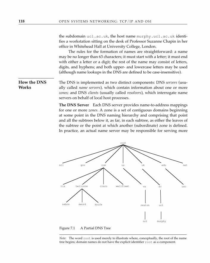
the subdomain ucl.ac.uk, the host name murphy.ucl.ac.uk identi-fies a workstation sitting on the desk of Professor Suzanne Chapin in heroffice in Whitehead Hall at University College, London.
The rules for the formation of names are straightforward: a namemay be no longer than 63 characters; it must start with a letter; it must endwith either a letter or a digit; the rest of the name may consist of letters,digits, and hyphens; and both upper- and lowercase letters may be used(although name lookups in the DNS are defined to be case-insensitive).
The DNS is implemented as two distinct components: DNS servers (usu-ally called name servers), which contain information about one or morezones; and DNS clients (usually called resolvers), which interrogate nameservers on behalf of local host processes.
The DNS Server—Each DNS server provides name-to-address mappingsfor one or more zones. A zone is a set of contiguous domains beginningat some point in the DNS naming hierarchy and comprising that pointand all the subtrees below it, as far, in each subtree, as either the leaves ofthe subtree or the point at which another (subordinate) zone is defined.In practice, an actual name server may be responsible for serving more
O P E N S Y S T E M S N E T W O R K I N G : T C P / I P A N D O S I118
How the DNSWorks
root
com edu
bellcore
sabre sword knife
ciscotis
govmil net
wellfleet
ukus
va
reston
nri
ac
ucl
usc
murphy
Figure 7.1 A Partial DNS Tree
Note: The word root is used merely to illustrate where, conceptually, the root of the nametree begins; domain names do not have the explicit identifier root as a component.
D I R E C T O R I E S 119
than one zone and will generally also serve the reverse in-addr.arpazones (see “‘Reverse’ Lookups,” later in the chapter) that correspond toits local domains.
Secondary name servers can be identified for each zone, so that nameresolution for that zone is not cut off when the primary name server, orthe links to it, are lost.
The DNS Resolver—A DNS name server not only stores and managesinformation about domains; it also responds to queries concerning thatinformation from client processes or resolvers. A resolver is typically a setof library routines that are invoked by an application program when itneeds to resolve a name reference. In BSD UNIX, for example, the rou-tines are gethostbyname and gethostbyaddr. The resolver takes thename and uses it to query either a local table6 (if the reference is to alocally maintained name or to a name that the resolver has maintained ina local cache) or one or more DNS servers for corresponding resourcerecords.
The resolver’s most significant task is to formulate a proper query.Since the DNS works with fully qualified names, this may involve a bitof interpretation on the part of the resolver, which may be presented byits user with a name that is not fully qualified. Some resolvers abdicatethis responsibility entirely and are capable of looking up only the namestring exactly as provided by the user. Others are able to recognize a lessthan fully qualified name and supply the missing high-order domainspecification automatically (defaulting, for example, to the domain inwhich the user’s own host resides).
Clients and servers use a common format for DNS queries andreplies. Basically, a client provides a unique identifier (so it can later matchresponses to queries) and poses a number of questions the server shouldattempt to resolve. In the case of name-to-address lookups, each questionis an entry of the form {query domain name, type, class}; in this example,the domain name to be resolved is provided, the query type is set to avalue indicating that the client is looking for an IP address, and the queryclass is set to a value indicating which object class (Internet domainnames) is to be interrogated. The server returns a similarly formatted
6. Many resolvers have sophisticated methods of caching domain names, to reducedelay in resolving DNS queries. A frequent practice is to request and copy an entire DNSserver’s name information, then periodically send consistency-check inquiries to the DNSserver. Two benefits are introduced when hosts practice caching: first, the processing of aDNS inquiry is faster, because there is no DNS client/server (protocol) interaction; second,if a server becomes unreachable, the local resolver can continue to satisfy lookups usingthe cache.
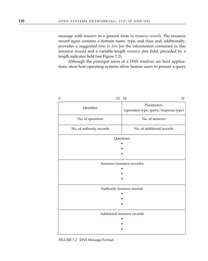
O P E N S Y S T E M S N E T W O R K I N G : T C P / I P A N D O S I120
message with answers in a general form (a resource record). The resourcerecord again contains a domain name, type, and class and, additionally,provides a suggested time to live for the information contained in thisresource record and a variable-length resource data field, preceded by alength indicator field (see Figure 7.2).
Although the principal users of a DNS resolver are host applica-tions, most host operating systems allow human users to present a query
ParametersIdentifier
(operation type, query/response type)
No. of questions No. of answers
No. of authority records No. of additional records
Questions•••
Answers (resource records)•••
Authority resource records•••
Additional resource records•••
0 15 16 31
FIGURE 7.2 DNS Message Format
directly, using, for example, a command such as the UNIX nslookup,which, in the SunOS version, looks like this:
% /usr/etc/nslookupDefault Server: nameserver.bbn.comAddress: 128.89.1.2
> nic.ddn.milServer: nameserver.bbn.comAddress: 128.89.1.2
Name: nic.ddn.milAddress: 192.112.36.5
>exit
Most Internet applications, including common ones like FTP andTELNET, accept a domain name from the user and call a resolver inter-nally, so it is rarely necessary for a user to query the DNS directly (exceptout of curiosity and perhaps to trouble-shoot networking problems).
A special domain within the domain name space, in-addr.arpa, pro-vides a mechanism for performing “reverse” lookups—that is, finding thename associated with a given address. The entries in the in-addr. arpadomain are constructed by reversing the order of the components of a net-work number (the first 1, 2, or 3 bytes of an IP address, depending onwhether the address is a class-A, class-B, or class-C address; see Chapter13), and appending the in-addr.arpa domain name. Thus, for example,the entry for BBN’s class-B network number, 128.89.0.0, would be89.128.in-addr.arpa; a lookup on this entry would return thedomain name bbn.com. Individual host systems, such as the Macintoshon the desk in Lyman Chapin’s office at BBN, appear as subdomains of thenetwork-number domain; for example, 224.16.89.128.in-addr.arpa.
The DNS also plays an important role in electronic-mail service (seeChapter 8). A host acting as a mail transfer agent must know the hostname and IP address of the host to which a mail message is to be deliveredbefore it attempts the delivery. It extracts the domain name part from thedestination mail address (again, see Chapter 8), and creates a query with aquestion of query type MX (for “mail exchange”). The DNS server returnsan answer with one or more MX resource records. Each MX record identi-fies a host to which mail may be forwarded, with each host domain nameaccompanied by an indication of how desirable it is to use this host for for-warding mail relative to others in the list (a preference field).
D I R E C T O R I E S 121
Mail Exchange
“Reverse”Lookups
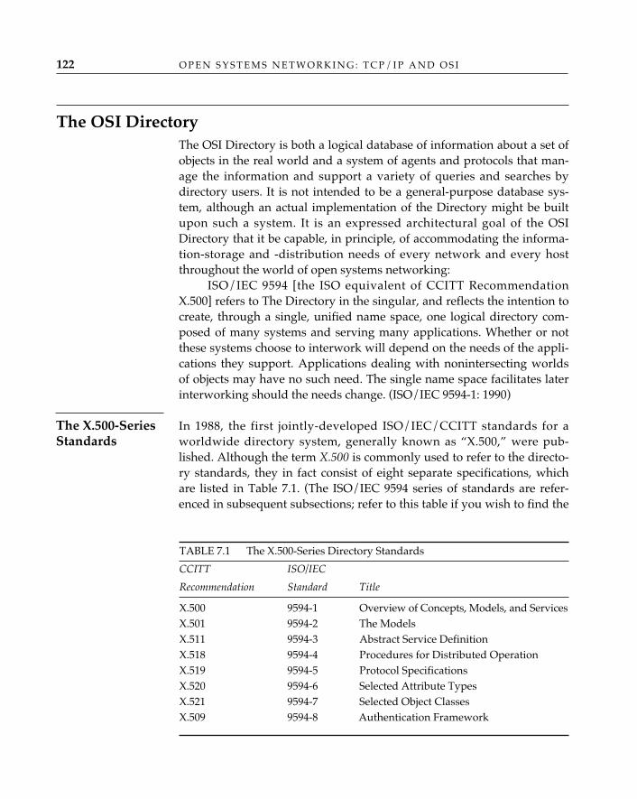
The OSI DirectoryThe OSI Directory is both a logical database of information about a set ofobjects in the real world and a system of agents and protocols that man-age the information and support a variety of queries and searches bydirectory users. It is not intended to be a general-purpose database sys-tem, although an actual implementation of the Directory might be builtupon such a system. It is an expressed architectural goal of the OSIDirectory that it be capable, in principle, of accommodating the informa-tion-storage and -distribution needs of every network and every hostthroughout the world of open systems networking:
ISO/IEC 9594 [the ISO equivalent of CCITT RecommendationX.500] refers to The Directory in the singular, and reflects the intention tocreate, through a single, unified name space, one logical directory com-posed of many systems and serving many applications. Whether or notthese systems choose to interwork will depend on the needs of the appli-cations they support. Applications dealing with nonintersecting worldsof objects may have no such need. The single name space facilitates laterinterworking should the needs change. (ISO/IEC 9594-1: 1990)
In 1988, the first jointly-developed ISO/IEC/CCITT standards for aworldwide directory system, generally known as “X.500,” were pub-lished. Although the term X.500 is commonly used to refer to the directo-ry standards, they in fact consist of eight separate specifications, whichare listed in Table 7.1. (The ISO/IEC 9594 series of standards are refer-enced in subsequent subsections; refer to this table if you wish to find the
O P E N S Y S T E M S N E T W O R K I N G : T C P / I P A N D O S I122
The X.500-SeriesStandards
TABLE 7.1 The X.500-Series Directory Standards
CCITT ISO/IEC
Recommendation Standard Title
X.500 9594-1 Overview of Concepts, Models, and ServicesX.501 9594-2 The ModelsX.511 9594-3 Abstract Service DefinitionX.518 9594-4 Procedures for Distributed OperationX.519 9594-5 Protocol SpecificationsX.520 9594-6 Selected Attribute TypesX.521 9594-7 Selected Object ClassesX.509 9594-8 Authentication Framework
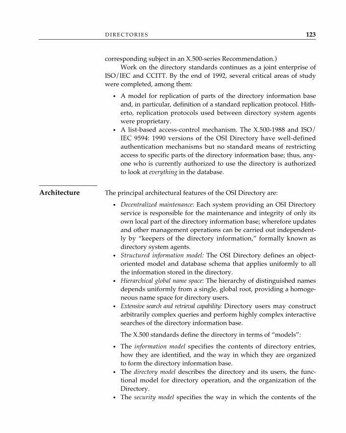
corresponding subject in an X.500-series Recommendation.)Work on the directory standards continues as a joint enterprise of
ISO/IEC and CCITT. By the end of 1992, several critical areas of studywere completed, among them:
• A model for replication of parts of the directory information baseand, in particular, definition of a standard replication protocol. Hith-erto, replication protocols used between directory system agentswere proprietary.
• A list-based access-control mechanism. The X.500-1988 and ISO/IEC 9594: 1990 versions of the OSI Directory have well-definedauthentication mechanisms but no standard means of restrictingaccess to specific parts of the directory information base; thus, any-one who is currently authorized to use the directory is authorizedto look at everything in the database.
The principal architectural features of the OSI Directory are:
• Decentralized maintenance: Each system providing an OSI Directoryservice is responsible for the maintenance and integrity of only itsown local part of the directory information base; wherefore updatesand other management operations can be carried out independent-ly by “keepers of the directory information,” formally known asdirectory system agents.
• Structured information model: The OSI Directory defines an object-oriented model and database schema that applies uniformly to allthe information stored in the directory.
• Hierarchical global name space: The hierarchy of distinguished namesdepends uniformly from a single, global root, providing a homoge-neous name space for directory users.
• Extensive search and retrieval capability: Directory users may constructarbitrarily complex queries and perform highly complex interactivesearches of the directory information base.
The X.500 standards define the directory in terms of “models”:
• The information model specifies the contents of directory entries,how they are identified, and the way in which they are organizedto form the directory information base.
• The directory model describes the directory and its users, the func-tional model for directory operation, and the organization of theDirectory.
• The security model specifies the way in which the contents of the
D I R E C T O R I E S 123
Architecture
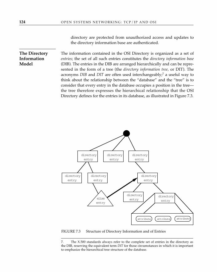
directory are protected from unauthorized access and updates tothe directory information base are authenticated.
The information contained in the OSI Directory is organized as a set ofentries; the set of all such entries constitutes the directory information base(DIB). The entries in the DIB are arranged hierarchically and can be repre-sented in the form of a tree (the directory information tree, or DIT). Theacronyms DIB and DIT are often used interchangeably;7 a useful way tothink about the relationship between the “database” and the “tree” is toconsider that every entry in the database occupies a position in the tree—the tree therefore expresses the hierarchical relationship that the OSIDirectory defines for the entries in its database, as illustrated in Figure 7.3.
O P E N S Y S T E M S N E T W O R K I N G : T C P / I P A N D O S I124
The DirectoryInformationModel
7. The X.500 standards always refer to the complete set of entries in the directory asthe DIB, reserving the equivalent term DIT for those circumstances in which it is importantto emphasize the hierarchical tree structure of the database.
directoryentry
directoryentry
directoryentry
directoryentry
directoryentry
directoryentry
directoryentry
directoryentry
attribute attribute attribute
aliasentry
FIGURE 7.3 Structure of Directory Information and of Entries
D I R E C T O R I E S 125
Directory Entries and Attributes—The ASN.1 encoding of a directoryentry is:
Attribute ::=SEQUENCE {
type AttributeType,values SET OF AttributeValue }
AttributeType ::= OBJECT IDENTIFIER
AttributeValue ::= ANY
Each directory entry consists of a set of attributes, each of whichconsists of an attribute type, which identifies the class of informationgiven by the attribute, and one or more corresponding attribute values,which are particular instances of that class of information (see Figure7.4). An entry may not contain more than one attribute of a given type.
What sort of things are attributes? Virtually anything that describesan object for which a directory entry is created. Some attribute types are
FIGURE 7.4 Directory Entries and Attributes
..
..
DIBEntry
Attributetype
Attributevalue(s)
Attribute
Attribute value(s
Attributevalue
Attributevalue
Distinguishedattributevalue
EntryEntryEntry
Attribute Attribute Attribute
O P E N S Y S T E M S N E T W O R K I N G : T C P / I P A N D O S I126
internationally standardized. A set of “selected attribute types,” consid-ered by the standards committees to be widely applicable, is provided inISO/IEC 9594-6: 1990; they include:
• Labeling attribute types: Common Name, Surname, Serial Number• Geographic attribute types: Country Name, Locality Name, State or
Province Name, Street Address• Organizational attribute types: Organization Name, Organizational
Unit, Title• Postal-addressing attribute types: Postal Address, Postal Code, Post
Office Box, Physical Delivery Office Name• Telecommunications-addressing attribute types: Telephone Number,
Telex Number, Teletex Terminal Identifier, Facsimile TelephoneNumber, X.121 address, ISDN Number, Registered Address
• OSI application attribute types: Presentation Address, SupportedApplication Context
This is but a sampling. Other attributes are defined by nationaladministrative authorities or private organizations. For example, it is per-fectly appropriate to imagine a set of attributes for the medical profes-sion, including residency or attending physician attributes (where? howmany years? under whom? area[s] of specialization? publications, honorsreceived, recommendations, evaluations, hours of practice?) and mal-practice attributes (insurance carrier, annual premium, suits pending,suits settled). In other words, you can assume that organizations or indi-viduals can create an attribute type for anything they wish to use to dis-tinguish an individual or an object from another of its class.
In order to ensure that attribute types are assigned in such a waythat each is distinct from all other assigned types, they are identified byan object identifier. The syntax (and hence, the data type) of attribute val-ues for a particular attribute type is specified when the attribute type isdefined.
An attribute value assertion (AVA) is a proposition—which may betrue, false, or undefined—concerning the value(s) (or in some cases, onlythe distinguished values; see the following paragraphs) of an entry; it isusually expressed as a sequence of one or more statements of the formAttributeType = AttributeValue.
Directory Names—At most, one of the values of an attribute may be des-ignated as a distinguished value—in which case, the value appears in therelative distinguished name (RDN) of the entry. Every entry has a uniquerelative distinguished name, which consists of a set of attribute valueassertions (each of which is true) concerning the distinguished values of
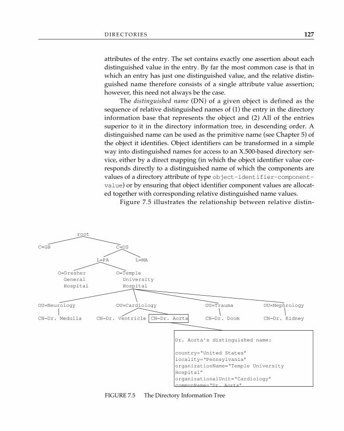
root
C=GB C=US
L=PA L=MA
O=Dresher O=TempleGeneral UniversityHospital Hospital
OU=Neurology OU=Cardiology OU=Trauma OU=Nephrology
CN=Dr. Medulla CN=Dr. Ventricle CN=Dr. Aorta CN=Dr. Doom CN=Dr. Kidney
D I R E C T O R I E S 127
attributes of the entry. The set contains exactly one assertion about eachdistinguished value in the entry. By far the most common case is that inwhich an entry has just one distinguished value, and the relative distin-guished name therefore consists of a single attribute value assertion;however, this need not always be the case.
The distinguished name (DN) of a given object is defined as thesequence of relative distinguished names of (1) the entry in the directoryinformation base that represents the object and (2) All of the entriessuperior to it in the directory information tree, in descending order. Adistinguished name can be used as the primitive name (see Chapter 5) ofthe object it identifies. Object identifiers can be transformed in a simpleway into distinguished names for access to an X.500-based directory ser-vice, either by a direct mapping (in which the object identifier value cor-responds directly to a distinguished name of which the components arevalues of a directory attribute of type object-identifier-component-value) or by ensuring that object identifier component values are allocat-ed together with corresponding relative distinguished name values.
Figure 7.5 illustrates the relationship between relative distin-
FIGURE 7.5 The Directory Information Tree
Dr. Aorta’s distinguished name:
country=“United States”locality=“Pennsylvania”organizationName=“Temple UniversityHospital”organizationalUnit=“Cardiology”commonName=“Dr. Aorta”
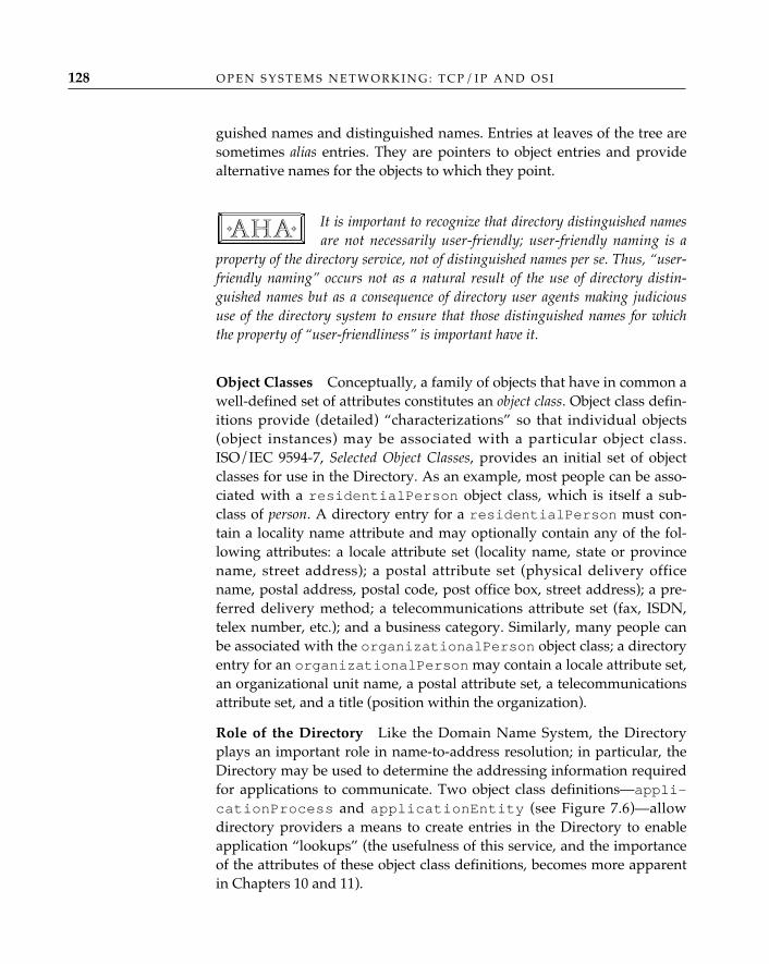
O P E N S Y S T E M S N E T W O R K I N G : T C P / I P A N D O S I128
guished names and distinguished names. Entries at leaves of the tree aresometimes alias entries. They are pointers to object entries and providealternative names for the objects to which they point.
It is important to recognize that directory distinguished namesare not necessarily user-friendly; user-friendly naming is a
property of the directory service, not of distinguished names per se. Thus, “user-friendly naming” occurs not as a natural result of the use of directory distin-guished names but as a consequence of directory user agents making judicioususe of the directory system to ensure that those distinguished names for whichthe property of “user-friendliness” is important have it.
Object Classes—Conceptually, a family of objects that have in common awell-defined set of attributes constitutes an object class. Object class defin-itions provide (detailed) “characterizations” so that individual objects(object instances) may be associated with a particular object class.ISO/IEC 9594-7, Selected Object Classes, provides an initial set of objectclasses for use in the Directory. As an example, most people can be asso-ciated with a residentialPerson object class, which is itself a sub-class of person. A directory entry for a residentialPerson must con-tain a locality name attribute and may optionally contain any of the fol-lowing attributes: a locale attribute set (locality name, state or provincename, street address); a postal attribute set (physical delivery officename, postal address, postal code, post office box, street address); a pre-ferred delivery method; a telecommunications attribute set (fax, ISDN,telex number, etc.); and a business category. Similarly, many people canbe associated with the organizationalPerson object class; a directoryentry for an organizationalPerson may contain a locale attribute set,an organizational unit name, a postal attribute set, a telecommunicationsattribute set, and a title (position within the organization).
Role of the Directory—Like the Domain Name System, the Directoryplays an important role in name-to-address resolution; in particular, theDirectory may be used to determine the addressing information requiredfor applications to communicate. Two object class definitions—appli-cationProcess and applicationEntity (see Figure 7.6)—allowdirectory providers a means to create entries in the Directory to enableapplication “lookups” (the usefulness of this service, and the importanceof the attributes of these object class definitions, becomes more apparentin Chapters 10 and 11).
✧AHA✧
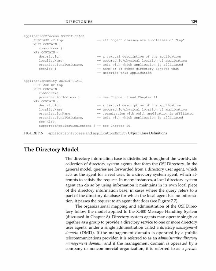
D I R E C T O R I E S 129
The Directory Model
The directory information base is distributed throughout the worldwidecollection of directory system agents that form the OSI Directory. In thegeneral model, queries are forwarded from a directory user agent, whichacts as the agent for a real user, to a directory system agent, which at-tempts to satisfy the request. In many instances, a local directory systemagent can do so by using information it maintains in its own local pieceof the directory information base; in cases where the query refers to apart of the directory database for which the local agent has no informa-tion, it passes the request to an agent that does (see Figure 7.7).
The organizational mapping and administration of the OSI Direc-tory follow the model applied to the X.400 Message Handling System(discussed in Chapter 8). Directory system agents may operate singly ortogether as a group to provide a directory service to one or more directoryuser agents, under a single administration called a directory managementdomain (DMD). If the management domain is operated by a publictelecommunications provider, it is referred to as an administrative directorymanagement domain, and if the management domain is operated by acompany or noncommercial organization, it is referred to as a private
applicationProcess OBJECT-CLASSSUBCLASS of top -- all object classes are subclasses of “top”MUST CONTAIN {
commonName }MAY CONTAIN {
description, -- a textual description of the applicationlocalityName, -- geographic/physical location of applicationorganizationalUnitName, -- unit with which application is affiliatedseeAlso } -- name(s) of other directory objects that
-- describe this application
applicationEntity OBJECT-CLASSSUBCLASS OF topMUST CONTAIN {
commonName,presentationAddress } -- see Chapter 5 and Chapter 11
MAY CONTAIN {description, -- a textual description of the applicationlocalityName, -- geographic/physical location of applicationorganizationName, -- organization with which application is affiliatedorganizationalUnitName, -- unit with which application is affiliatedsee Also,supportedApplicationContext } -- see Chapter 10
FIGURE 7.6 applicationProcess and applicationEntity Object Class Definitions
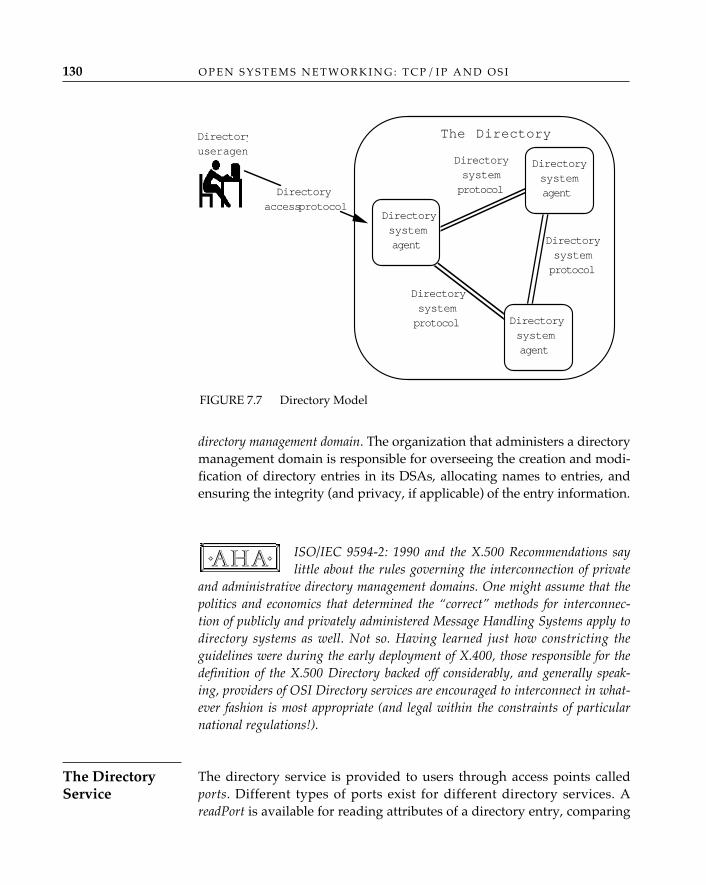
O P E N S Y S T E M S N E T W O R K I N G : T C P / I P A N D O S I130
directory management domain. The organization that administers a directorymanagement domain is responsible for overseeing the creation and modi-fication of directory entries in its DSAs, allocating names to entries, andensuring the integrity (and privacy, if applicable) of the entry information.
ISO/IEC 9594-2: 1990 and the X.500 Recommendations saylittle about the rules governing the interconnection of private
and administrative directory management domains. One might assume that thepolitics and economics that determined the “correct” methods for interconnec-tion of publicly and privately administered Message Handling Systems apply todirectory systems as well. Not so. Having learned just how constricting theguidelines were during the early deployment of X.400, those responsible for thedefinition of the X.500 Directory backed off considerably, and generally speak-ing, providers of OSI Directory services are encouraged to interconnect in what-ever fashion is most appropriate (and legal within the constraints of particularnational regulations!).
The directory service is provided to users through access points calledports. Different types of ports exist for different directory services. AreadPort is available for reading attributes of a directory entry, comparing
✧AHA✧
FIGURE 7.7 Directory Model
Directoryuser agent
The Directory
Directorysystemprotocol
Directorysystemagent
Directorysystemagent
Directorysystemagent
Directoryaccess protocol
Directorysystemprotocol
Directorysystemprotocol
The DirectoryService
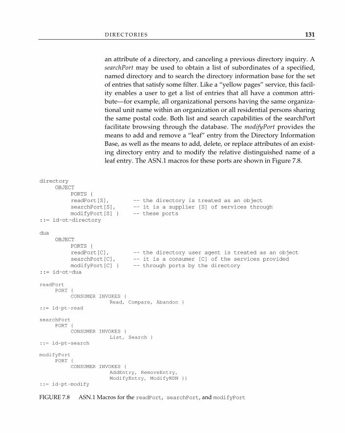
an attribute of a directory, and canceling a previous directory inquiry. AsearchPort may be used to obtain a list of subordinates of a specified,named directory and to search the directory information base for the setof entries that satisfy some filter. Like a “yellow pages” service, this facil-ity enables a user to get a list of entries that all have a common attri-bute—for example, all organizational persons having the same organiza-tional unit name within an organization or all residential persons sharingthe same postal code. Both list and search capabilities of the searchPortfacilitate browsing through the database. The modifyPort provides themeans to add and remove a “leaf” entry from the Directory InformationBase, as well as the means to add, delete, or replace attributes of an exist-ing directory entry and to modify the relative distinguished name of aleaf entry. The ASN.1 macros for these ports are shown in Figure 7.8.
D I R E C T O R I E S 131
FIGURE 7.8 ASN.1 Macros for the readPort, searchPort, and modifyPort
directoryOBJECT
PORTS {readPort[S], -- the directory is treated as an object searchPort[S], -- it is a supplier [S] of services throughmodifyPort[S] } -- these ports
::= id-ot-directory
duaOBJECT
PORTS {readPort[C], -- the directory user agent is treated as an objectsearchPort[C], -- it is a consumer [C] of the services providedmodifyPort[C] } -- through ports by the directory
::= id-ot-dua
readPortPORT {
CONSUMER INVOKES {Read, Compare, Abandon }
::= id-pt-read
searchPortPORT {
CONSUMER INVOKES {List, Search }
::= id-pt-search
modifyPortPORT {
CONSUMER INVOKES {AddEntry, RemoveEntry,ModifyEntry, ModifyRDN }}
::= id-pt-modify
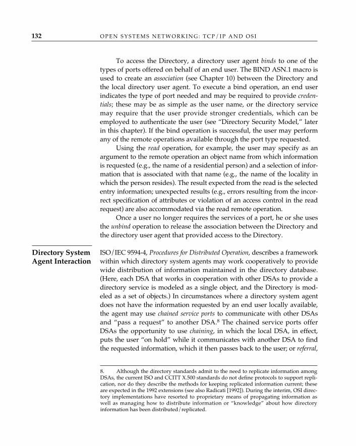
O P E N S Y S T E M S N E T W O R K I N G : T C P / I P A N D O S I132
To access the Directory, a directory user agent binds to one of thetypes of ports offered on behalf of an end user. The BIND ASN.1 macro isused to create an association (see Chapter 10) between the Directory andthe local directory user agent. To execute a bind operation, an end userindicates the type of port needed and may be required to provide creden-tials; these may be as simple as the user name, or the directory servicemay require that the user provide stronger credentials, which can beemployed to authenticate the user (see “Directory Security Model,” laterin this chapter). If the bind operation is successful, the user may performany of the remote operations available through the port type requested.
Using the read operation, for example, the user may specify as anargument to the remote operation an object name from which informationis requested (e.g., the name of a residential person) and a selection of infor-mation that is associated with that name (e.g., the name of the locality inwhich the person resides). The result expected from the read is the selectedentry information; unexpected results (e.g., errors resulting from the incor-rect specification of attributes or violation of an access control in the readrequest) are also accommodated via the read remote operation.
Once a user no longer requires the services of a port, he or she usesthe unbind operation to release the association between the Directory andthe directory user agent that provided access to the Directory.
ISO/IEC 9594-4, Procedures for Distributed Operation, describes a frameworkwithin which directory system agents may work cooperatively to providewide distribution of information maintained in the directory database.(Here, each DSA that works in cooperation with other DSAs to provide adirectory service is modeled as a single object, and the Directory is mod-eled as a set of objects.) In circumstances where a directory system agentdoes not have the information requested by an end user locally available,the agent may use chained service ports to communicate with other DSAsand “pass a request” to another DSA.8 The chained service ports offerDSAs the opportunity to use chaining, in which the local DSA, in effect,puts the user “on hold” while it communicates with another DSA to findthe requested information, which it then passes back to the user; or referral,
Directory SystemAgent Interaction
8. Although the directory standards admit to the need to replicate information amongDSAs, the current ISO and CCITT X.500 standards do not define protocols to support repli-cation, nor do they describe the methods for keeping replicated information current; theseare expected in the 1992 extensions (see also Radicati [1992]). During the interim, OSI direc-tory implementations have resorted to proprietary means of propagating information aswell as managing how to distribute information or “knowledge” about how directoryinformation has been distributed/replicated.
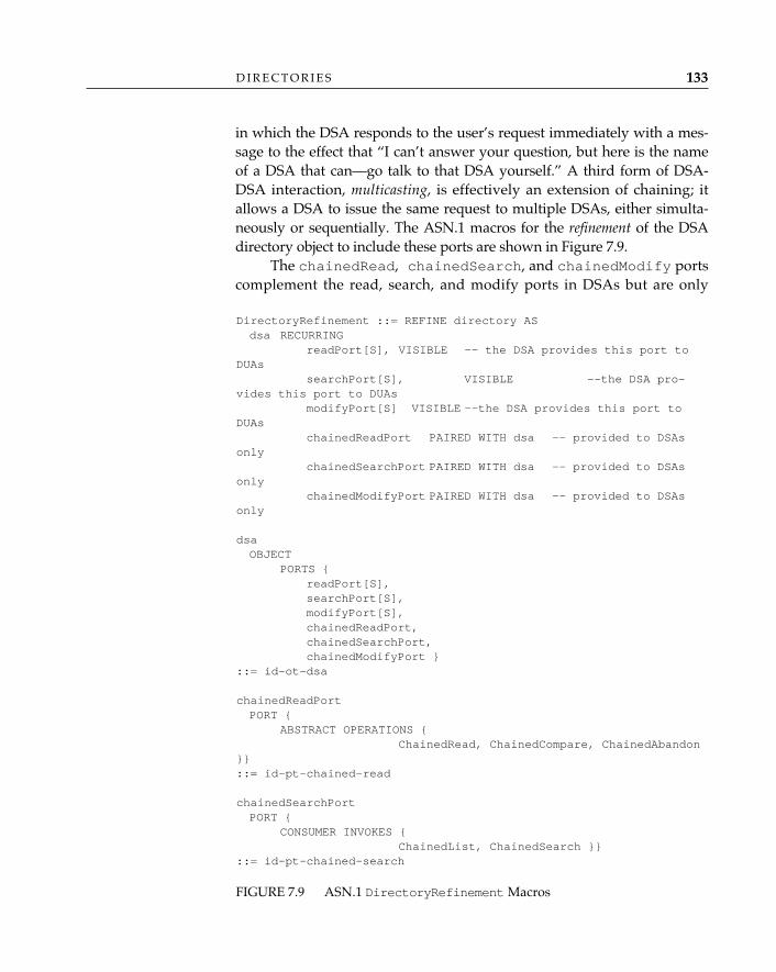
in which the DSA responds to the user’s request immediately with a mes-sage to the effect that “I can’t answer your question, but here is the nameof a DSA that can—go talk to that DSA yourself.” A third form of DSA-DSA interaction, multicasting, is effectively an extension of chaining; itallows a DSA to issue the same request to multiple DSAs, either simulta-neously or sequentially. The ASN.1 macros for the refinement of the DSAdirectory object to include these ports are shown in Figure 7.9.
The chainedRead, chainedSearch, and chainedModify portscomplement the read, search, and modify ports in DSAs but are only
D I R E C T O R I E S 133
DirectoryRefinement ::= REFINE directory ASdsa RECURRING
readPort[S], VISIBLE -- the DSA provides this port toDUAs
searchPort[S], VISIBLE --the DSA pro-vides this port to DUAs
modifyPort[S] VISIBLE --the DSA provides this port toDUAs
chainedReadPort PAIRED WITH dsa -- provided to DSAsonly
chainedSearchPort PAIRED WITH dsa -- provided to DSAsonly
chainedModifyPort PAIRED WITH dsa -- provided to DSAsonly
dsaOBJECT
PORTS {readPort[S],searchPort[S],modifyPort[S],chainedReadPort,chainedSearchPort,chainedModifyPort }
::= id-ot-dsa
chainedReadPortPORT {
ABSTRACT OPERATIONS {ChainedRead, ChainedCompare, ChainedAbandon
}}::= id-pt-chained-read
chainedSearchPortPORT {
CONSUMER INVOKES {ChainedList, ChainedSearch }}
::= id-pt-chained-search
FIGURE 7.9 ASN.1 DirectoryRefinement Macros
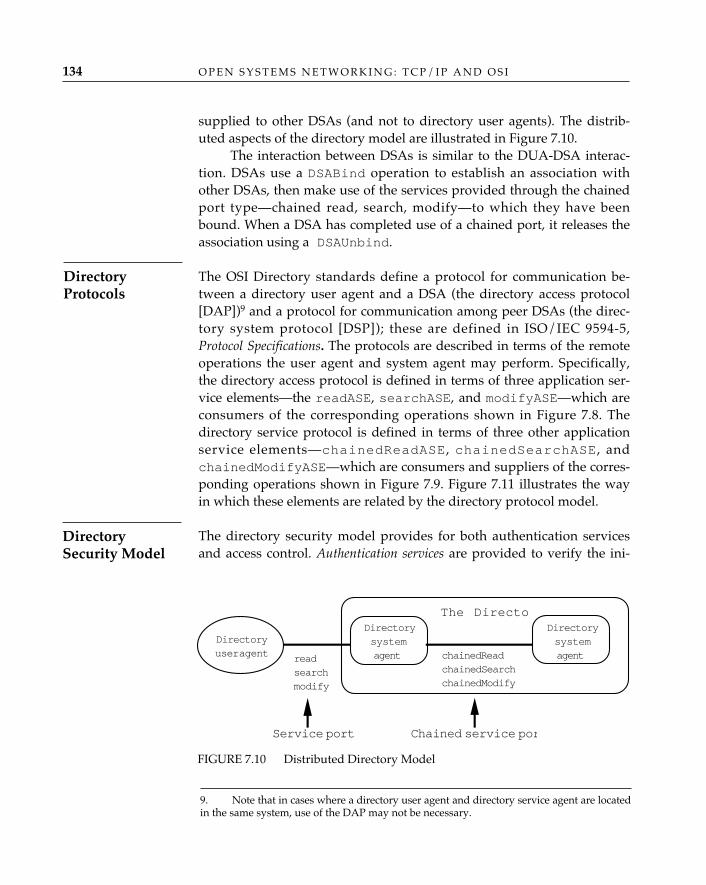
O P E N S Y S T E M S N E T W O R K I N G : T C P / I P A N D O S I134
supplied to other DSAs (and not to directory user agents). The distrib-uted aspects of the directory model are illustrated in Figure 7.10.
The interaction between DSAs is similar to the DUA-DSA interac-tion. DSAs use a DSABind operation to establish an association withother DSAs, then make use of the services provided through the chainedport type—chained read, search, modify—to which they have beenbound. When a DSA has completed use of a chained port, it releases theassociation using a DSAUnbind.
The OSI Directory standards define a protocol for communication be-tween a directory user agent and a DSA (the directory access protocol[DAP])9 and a protocol for communication among peer DSAs (the direc-tory system protocol [DSP]); these are defined in ISO/IEC 9594-5,Protocol Specifications. The protocols are described in terms of the remoteoperations the user agent and system agent may perform. Specifically,the directory access protocol is defined in terms of three application ser-vice elements—the readASE, searchASE, and modifyASE—which areconsumers of the corresponding operations shown in Figure 7.8. Thedirectory service protocol is defined in terms of three other applicationservice elements—chainedReadASE, chainedSearchASE, andchainedModifyASE—which are consumers and suppliers of the corres-ponding operations shown in Figure 7.9. Figure 7.11 illustrates the wayin which these elements are related by the directory protocol model.
The directory security model provides for both authentication servicesand access control. Authentication services are provided to verify the ini-
9. Note that in cases where a directory user agent and directory service agent are locatedin the same system, use of the DAP may not be necessary.
DirectoryProtocols
FIGURE 7.10 Distributed Directory Model
Directoryuser agent
Directorysystemagent
Directorysystemagentread
searchmodify
chainedReadchainedSearchchainedModify
The Directo
Service port Chained service por
DirectorySecurity Model
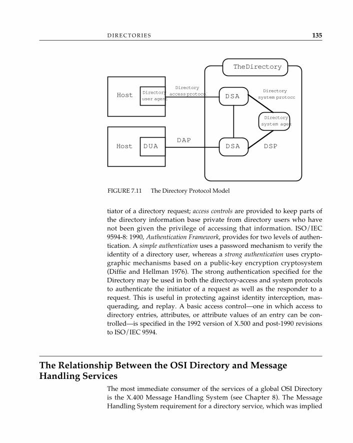
tiator of a directory request; access controls are provided to keep parts ofthe directory information base private from directory users who havenot been given the privilege of accessing that information. ISO/IEC9594-8: 1990, Authentication Framework, provides for two levels of authen-tication. A simple authentication uses a password mechanism to verify theidentity of a directory user, whereas a strong authentication uses crypto-graphic mechanisms based on a public-key encryption cryptosystem(Diffie and Hellman 1976). The strong authentication specified for theDirectory may be used in both the directory-access and system protocolsto authenticate the initiator of a request as well as the responder to arequest. This is useful in protecting against identity interception, mas-querading, and replay. A basic access control—one in which access todirectory entries, attributes, or attribute values of an entry can be con-trolled—is specified in the 1992 version of X.500 and post-1990 revisionsto ISO/IEC 9594.
The Relationship Between the OSI Directory and MessageHandling Services
The most immediate consumer of the services of a global OSI Directoryis the X.400 Message Handling System (see Chapter 8). The MessageHandling System requirement for a directory service, which was implied
D I R E C T O R I E S 135
FIGURE 7.11 The Directory Protocol Model
DSA
DSA
Host
DUADAP
DSP
The Directory
Directory
user agent
Directory
access protocol
Host
Directory
system protoco
Directory
system agent
O P E N S Y S T E M S N E T W O R K I N G : T C P / I P A N D O S I136
but not stated in the 1984 version of the X.400-series Recommendations,is explicit in the 1988 and later versions. In the 1984 version, the origina-tor/recipient (O/R) name used to identify the sources and destinations ofmail messages could be only one thing: an O/R address. In the 1988 andlater versions of the standard, an O/R name can be either an O/Raddress (as before) or a directory name (that is, a distinguished name inthe context of the X.500 Directory). The 1988 and later versions requirethat a directory service be either directly or indirectly accessible to themessage transfer systems of a message handling system.
A message handling system is likely to make use of a directory sys-tem for at least the following services:
• User-friendly O/R names: If the O/R names for mail users may onlybe O/R addresses, users must deal directly (and frequently!) withlengthy, cumbersome, and pedantic strings such as /c=us/admd=mcimail/prmd=nermc/o=bbn/s=Chapin/g=Lyman.If, on the other hand, a relative distinguished name in the Directorymay be used as an O/R name, then mail users may deal directlywith much friendlier (for one thing, shorter!) strings, such as“Lyman Chapin” (a clear improvement). In this example (andassuming that the Directory has been properly configured to placethe “Lyman Chapin” relative distinguished name at the appropriateplace in the directory information tree), a distinguished name entrywould appear in the directory for c=us@o=nermc@ou=bbn@commonName=Lyman Chapin, which can be transformed in astraightforward (and standardized) way into an O/R address.
• Expansion of distribution lists: When multiple recipients of electronicmail are combined in a distribution list, the name of the list canappear as the O/R name in a mail message. The Directory can beemployed to support the use of a user-friendly directory name,rather than an O/R address, for a distribution list, in the same wayas it supports the use of directory names for individual messagerecipients. It can also be used to support the expansion of a distri-bution list by the message transfer agents responsible for it, sincethe Directory can store all the O/R addresses for the message recip-ients included in a distribution list under the single relative distin-guished name of the distribution list.
• Message Handling System user searches: A Message Handling Systemuser who lacks sufficient information about a message re-cipient toproperly address a message may—outside of the Message HandlingSystem itself—use the search capabilities of the Directory to find themissing information (for example, the recipient’s full “common
D I R E C T O R I E S 137
name”) based on whatever partial information the user may have(such as, perhaps, the recipient’s first name and phone number).
The components of the X.400 Message Handling System use theDirectory in the same way as any other Directory user; there are no spe-cial protocols linking X.400 components to X.500 DUAs or DSAs. Thedirectory service required by the 1988 and later X.400 standards need not,therefore, be provided by X.500, nor indeed by any “global” directory.Each Message Handling System component deals with a local DUA orDUA equivalent, and no formal coupling between the Message HandlingSystem and the Directory is required as a matter of conformance to thestandards.
The OSI Directory in the InternetThe X.500 Directory is potentially far more powerful and comprehensivethan the patchwork combination of hosts.txt files, Domain NameSystem, and other information services and locators that are currentlyused to perform directorylike functions in the Internet. Since the ap-proval of the 1988 X.500 Directory Recommendations, there has beenconsiderable interest in the use of the OSI Directory in the TCP/IPInternet.10 A very large number of “pilot” projects—experiments in theuse of the OSI Directory service in the Internet—are today operationaland interconnected. They share a common global root directory main-tained at the University of London Computer Centre by the PARADISEproject.
PARADISE, the COSINE X.500 Directory service pilot, was launched inNovember 1990 to coordinate an international directory service for theEuropean research and development community. PARADISE providessome services itself, such as a user interface to the directory service, and as ofNovember 1991, also serves as a link between national pilots in the 18 coun-tries that are participating in COSINE. PARADISE is managed by UniversityCollege, London, and involves the University of London Computer Centre,X-Tel Services, and a group of public service providers, including PTTTelecom in the Netherlands, PTT Switzerland, and Telecom Finland.
PARADISE
10. The use of the term TCP/IP Internet here is intentional; it refers to the use of the OSIDirectory to maintain information about the traditional TCP/IP protocol suite in theInternet, in addition to its use to maintain information about OSI protocols that may besupported by a multiprotocol Internet.
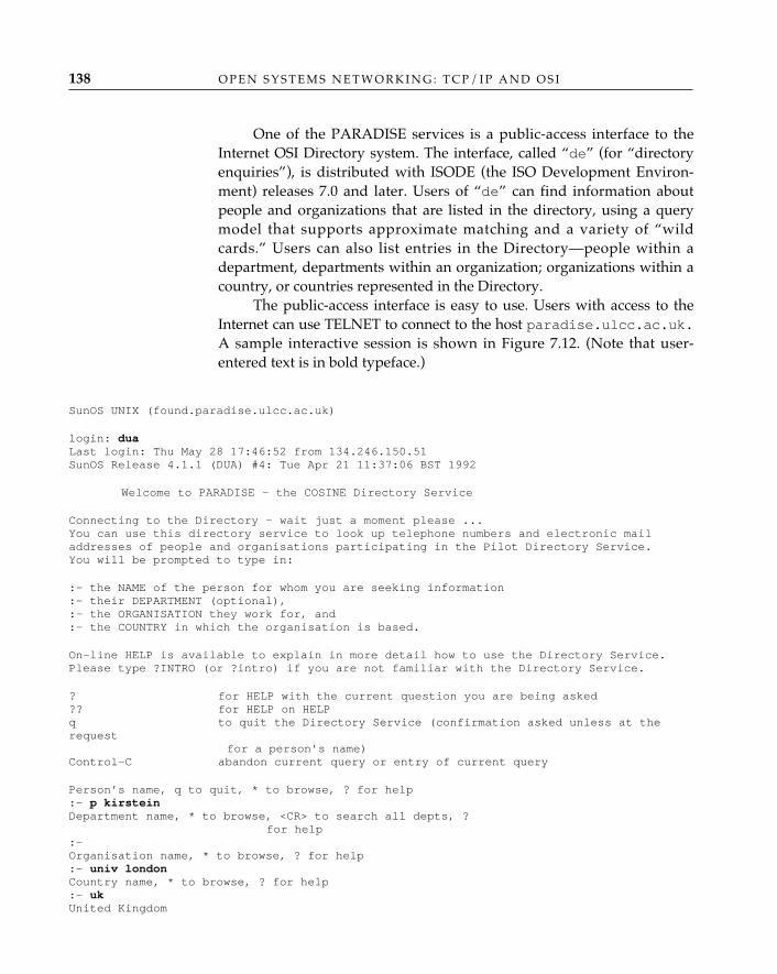
One of the PARADISE services is a public-access interface to theInternet OSI Directory system. The interface, called “de” (for “directoryenquiries”), is distributed with ISODE (the ISO Development Environ-ment) releases 7.0 and later. Users of “de” can find information aboutpeople and organizations that are listed in the directory, using a querymodel that supports approximate matching and a variety of “wildcards.” Users can also list entries in the Directory—people within adepartment, departments within an organization; organizations within acountry, or countries represented in the Directory.
The public-access interface is easy to use. Users with access to theInternet can use TELNET to connect to the host paradise.ulcc.ac.uk.A sample interactive session is shown in Figure 7.12. (Note that user-entered text is in bold typeface.)
SunOS UNIX (found.paradise.ulcc.ac.uk)
login: duaLast login: Thu May 28 17:46:52 from 134.246.150.51SunOS Release 4.1.1 (DUA) #4: Tue Apr 21 11:37:06 BST 1992
Welcome to PARADISE - the COSINE Directory Service
Connecting to the Directory - wait just a moment please ...You can use this directory service to look up telephone numbers and electronic mailaddresses of people and organisations participating in the Pilot Directory Service. You will be prompted to type in:
:- the NAME of the person for whom you are seeking information:- their DEPARTMENT (optional),:- the ORGANISATION they work for, and:- the COUNTRY in which the organisation is based.
On-line HELP is available to explain in more detail how to use the Directory Service.Please type ?INTRO (or ?intro) if you are not familiar with the Directory Service.
? for HELP with the current question you are being asked?? for HELP on HELPq to quit the Directory Service (confirmation asked unless at therequest
for a person’s name)Control-C abandon current query or entry of current query
Person’s name, q to quit, * to browse, ? for help:- p kirsteinDepartment name, * to browse, <CR> to search all depts, ?
for help:-Organisation name, * to browse, ? for help:- univ londonCountry name, * to browse, ? for help:- ukUnited Kingdom
O P E N S Y S T E M S N E T W O R K I N G : T C P / I P A N D O S I138
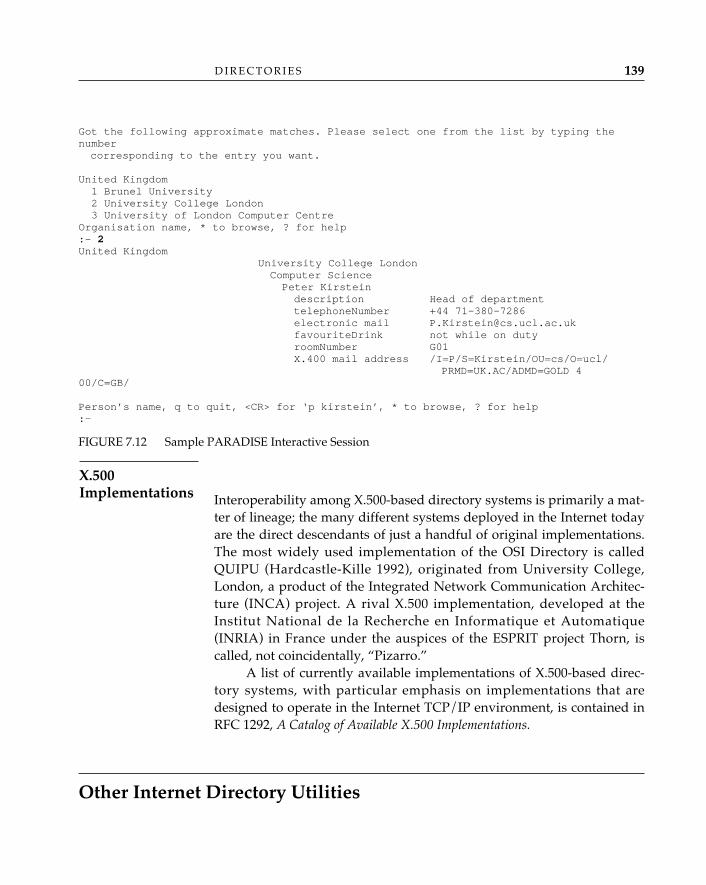
D I R E C T O R I E S 139
Got the following approximate matches. Please select one from the list by typing thenumber corresponding to the entry you want.
United Kingdom1 Brunel University2 University College London3 University of London Computer Centre
Organisation name, * to browse, ? for help:- 2United Kingdom
University College LondonComputer SciencePeter Kirsteindescription Head of departmenttelephoneNumber +44 71-380-7286electronic mail [email protected] not while on dutyroomNumber G01X.400 mail address /I=P/S=Kirstein/OU=cs/O=ucl/
PRMD=UK.AC/ADMD=GOLD 400/C=GB/
Person’s name, q to quit, <CR> for ‘p kirstein’, * to browse, ? for help:-
FIGURE 7.12 Sample PARADISE Interactive Session
Interoperability among X.500-based directory systems is primarily a mat-ter of lineage; the many different systems deployed in the Internet todayare the direct descendants of just a handful of original implementations.The most widely used implementation of the OSI Directory is calledQUIPU (Hardcastle-Kille 1992), originated from University College,London, a product of the Integrated Network Communication Architec-ture (INCA) project. A rival X.500 implementation, developed at theInstitut National de la Recherche en Informatique et Automatique(INRIA) in France under the auspices of the ESPRIT project Thorn, iscalled, not coincidentally, “Pizarro.”
A list of currently available implementations of X.500-based direc-tory systems, with particular emphasis on implementations that aredesigned to operate in the Internet TCP/IP environment, is contained inRFC 1292, A Catalog of Available X.500 Implementations.
Other Internet Directory Utilities
X.500Implementations
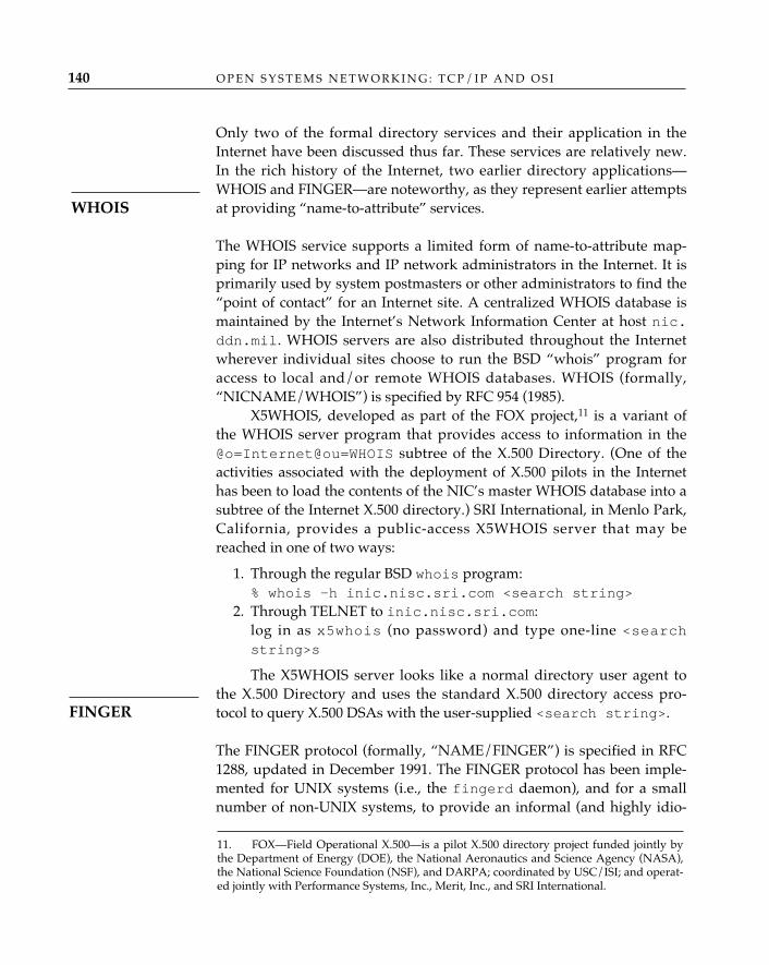
Only two of the formal directory services and their application in theInternet have been discussed thus far. These services are relatively new.In the rich history of the Internet, two earlier directory applications—WHOIS and FINGER—are noteworthy, as they represent earlier attemptsat providing “name-to-attribute” services.
The WHOIS service supports a limited form of name-to-attribute map-ping for IP networks and IP network administrators in the Internet. It isprimarily used by system postmasters or other administrators to find the“point of contact” for an Internet site. A centralized WHOIS database ismaintained by the Internet’s Network Information Center at host nic.ddn.mil. WHOIS servers are also distributed throughout the Internetwherever individual sites choose to run the BSD “whois” program foraccess to local and/or remote WHOIS databases. WHOIS (formally,“NICNAME/WHOIS”) is specified by RFC 954 (1985).
X5WHOIS, developed as part of the FOX project,11 is a variant ofthe WHOIS server program that provides access to information in the@o=Internet@ou=WHOIS subtree of the X.500 Directory. (One of theactivities associated with the deployment of X.500 pilots in the Internethas been to load the contents of the NIC’s master WHOIS database into asubtree of the Internet X.500 directory.) SRI International, in Menlo Park,California, provides a public-access X5WHOIS server that may bereached in one of two ways:
1. Through the regular BSD whois program:% whois -h inic.nisc.sri.com <search string>
2. Through TELNET to inic.nisc.sri.com:log in as x5whois (no password) and type one-line <searchstring>s
The X5WHOIS server looks like a normal directory user agent tothe X.500 Directory and uses the standard X.500 directory access pro-tocol to query X.500 DSAs with the user-supplied <search string>.
The FINGER protocol (formally, “NAME/FINGER”) is specified in RFC1288, updated in December 1991. The FINGER protocol has been imple-mented for UNIX systems (i.e., the fingerd daemon), and for a smallnumber of non-UNIX systems, to provide an informal (and highly idio-
O P E N S Y S T E M S N E T W O R K I N G : T C P / I P A N D O S I140
WHOIS
FINGER
11. FOX—Field Operational X.500—is a pilot X.500 directory project funded jointly bythe Department of Energy (DOE), the National Aeronautics and Science Agency (NASA),the National Science Foundation (NSF), and DARPA; coordinated by USC/ISI; and operat-ed jointly with Performance Systems, Inc., Merit, Inc., and SRI International.
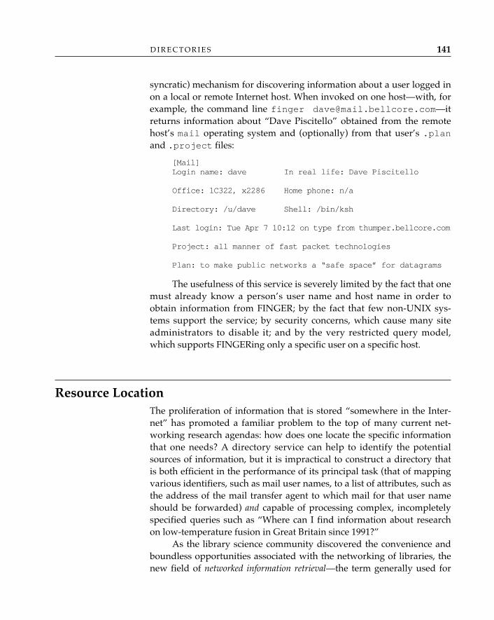
syncratic) mechanism for discovering information about a user logged inon a local or remote Internet host. When invoked on one host—with, forexample, the command line finger [email protected]—itreturns information about “Dave Piscitello” obtained from the remotehost’s mail operating system and (optionally) from that user’s .planand .project files:
[Mail] Login name: dave In real life: Dave Piscitello
Office: 1C322, x2286 Home phone: n/a
Directory: /u/dave Shell: /bin/ksh
Last login: Tue Apr 7 10:12 on type from thumper.bellcore.com
Project: all manner of fast packet technologies
Plan: to make public networks a “safe space” for datagrams
The usefulness of this service is severely limited by the fact that onemust already know a person’s user name and host name in order toobtain information from FINGER; by the fact that few non-UNIX sys-tems support the service; by security concerns, which cause many siteadministrators to disable it; and by the very restricted query model,which supports FINGERing only a specific user on a specific host.
Resource LocationThe proliferation of information that is stored “somewhere in the Inter-net” has promoted a familiar problem to the top of many current net-working research agendas: how does one locate the specific informationthat one needs? A directory service can help to identify the potentialsources of information, but it is impractical to construct a directory thatis both efficient in the performance of its principal task (that of mappingvarious identifiers, such as mail user names, to a list of attributes, such asthe address of the mail transfer agent to which mail for that user nameshould be forwarded) and capable of processing complex, incompletelyspecified queries such as “Where can I find information about researchon low-temperature fusion in Great Britain since 1991?”
As the library science community discovered the convenience andboundless opportunities associated with the networking of libraries, thenew field of networked information retrieval—the term generally used for
D I R E C T O R I E S 141
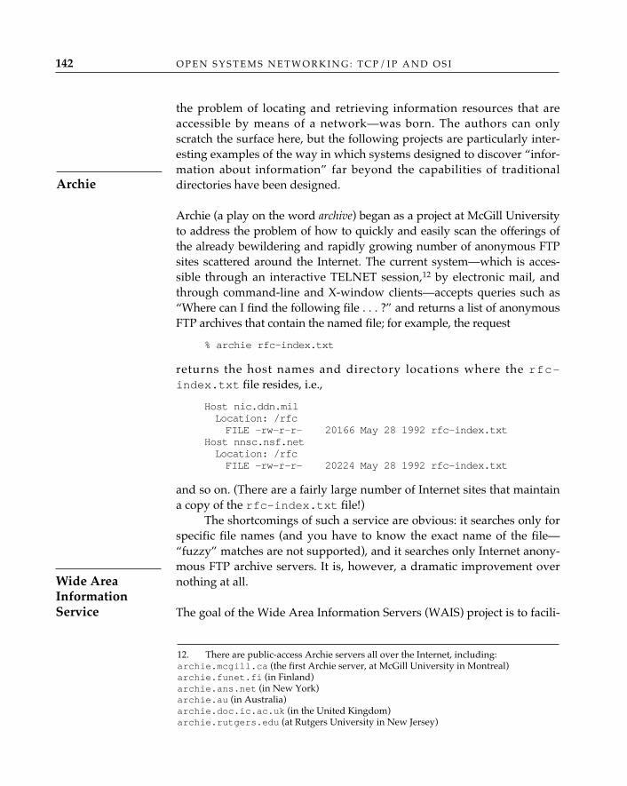
O P E N S Y S T E M S N E T W O R K I N G : T C P / I P A N D O S I142
the problem of locating and retrieving information resources that areaccessible by means of a network—was born. The authors can onlyscratch the surface here, but the following projects are particularly inter-esting examples of the way in which systems designed to discover “infor-mation about information” far beyond the capabilities of traditionaldirectories have been designed.
Archie (a play on the word archive) began as a project at McGill Universityto address the problem of how to quickly and easily scan the offerings ofthe already bewildering and rapidly growing number of anonymous FTPsites scattered around the Internet. The current system—which is acces-sible through an interactive TELNET session,12 by electronic mail, andthrough command-line and X-window clients—accepts queries such as“Where can I find the following file . . . ?” and returns a list of anonymousFTP archives that contain the named file; for example, the request
% archie rfc-index.txt
returns the host names and directory locations where the rfc-index.txt file resides, i.e.,
Host nic.ddn.milLocation: /rfcFILE -rw-r-r- 20166 May 28 1992 rfc-index.txt
Host nnsc.nsf.netLocation: /rfcFILE -rw-r-r- 20224 May 28 1992 rfc-index.txt
and so on. (There are a fairly large number of Internet sites that maintaina copy of the rfc-index.txt file!)
The shortcomings of such a service are obvious: it searches only forspecific file names (and you have to know the exact name of the file—“fuzzy” matches are not supported), and it searches only Internet anony-mous FTP archive servers. It is, however, a dramatic improvement overnothing at all.
The goal of the Wide Area Information Servers (WAIS) project is to facili-
Archie
12. There are public-access Archie servers all over the Internet, including:archie.mcgill.ca (the first Archie server, at McGill University in Montreal)archie.funet.fi (in Finland)archie.ans.net (in New York)archie.au (in Australia)archie.doc.ic.ac.uk (in the United Kingdom)archie.rutgers.edu (at Rutgers University in New Jersey)
Wide AreaInformationService
tate the growth of a distributed system of information servers and clientsbased on the ANSI standard bibliographic search and retrieval protocol(ANSI Z39.50-1988). WAIS is a much more ambitious undertaking thanArchie; it is a general-purpose search and retrieval system with two sig-nificant characteristics:
1. It uses the standard Z39.50 protocol to search documents and docu-ment indexes stored in a wide variety of repositories (not justInternet anonymous FTP archives).
2. It supports a unique, user-oriented search model that closelymatches the searching strategy with which people are alreadyfamiliar: (a) start with a few key words or phrases; (b) see whatWAIS retrieves; (c) tell WAIS which of the retrieved articles, or sec-tions of articles, are most relevant to the subject of your search andask it to search again using your selections as models; and (d)repeat the process until you’ve found what you want.
The “search from a good example” strategy makes WAIS a verypowerful tool, since it not only provides appropriate feedback to the userduring the search but also permits the scope or even the original purposeof the search to be changed, iteratively and interactively, as the searchproceeds. WAIS also has a built-in accounting system: the client searchscreens include an explicit “cost” field, which presents both a statementof what it costs (or would cost) to make a particular query and a runningdecremented count of “how much money you have left.”
WAIS uses Z39.50 over TCP/IP, modem, OSI, and other networks;the motivation for using a standard protocol is to eventually be able towork with a wide variety of standard bibliographic search and retrievalsystems that are being developed by the library science community. Itwas originally developed at Thinking Machines Corp. in Cambridge,Massachusetts, by Brewster Kahle, who turned it over to the WAISClearinghouse at the nonprofit Center for Communications Research atResearch Triangle Park near Charlotte, North Carolina.
A simple WAIS public-access interface is supported by the NSFnetNetwork Services Center; connect using TELNET to nnsc.nsf.net andlog in as wais, with no password.
The “WorldWideWeb” project is an ambitious attempt to make all on-line information readily accessible to users as a “web” of documents andlinks among them. It was originally developed in 1989 by Tim Berners-Lee, Robert Cailliau, and Jean-François Groff at CERN for use by thehigh-energy physics community but has expanded far beyond its origi-
D I R E C T O R I E S 143
WorldWideWeb
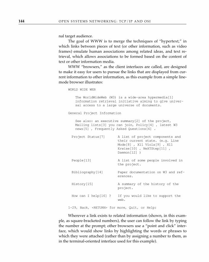
nal target audience.The goal of WWW is to merge the techniques of “hypertext,” in
which links between pieces of text (or other information, such as videoframes) emulate human associations among related ideas, and text re-trieval, which allows associations to be formed based on the content oftext or other information media.
WWW “browsers,” as the client interfaces are called, are designedto make it easy for users to pursue the links that are displayed from cur-rent information to other information, as this example from a simple line-mode browser illustrates:
WORLD WIDE WEB
The WorldWideWeb (W3) is a wide-area hypermedia[1] information retrieval initiative aiming to give univer-sal access to a large universe of documents.
General Project Information
See also: an executive summary[2] of the project, Mailing lists[3] you can join, Policy[4] , latest W3 news[5] , Frequently Asked Questions[6] .
Project Status[7] A list of project components and their current state. (e.g. Line Mode[8] , X11 Viola[9] , X11 Erwise[10] , NeXTStep[11] , Daemon[12] )
People[13] A list of some people involved in the project.
Bibliography[14] Paper documentation on W3 and ref-erences.
History[15] A summary of the history of the project.
How can I help[16] ? If you would like to support the web.
1-29, Back, <RETURN> for more, Quit, or Help:
Wherever a link exists to related information (shown, in this exam-ple, as square-bracketed numbers), the user can follow the link by typingthe number at the prompt; other browsers use a “point and click” inter-face, which would show links by highlighting the words or phrases towhich they were attached (rather than by assigning a number to them, asin the terminal-oriented interface used for this example).
O P E N S Y S T E M S N E T W O R K I N G : T C P / I P A N D O S I144

D I R E C T O R I E S 145
ConclusionThe Domain Name System is used in the Internet today principally toperform a mapping from some form of name to an Internet (IP) address.As the Internet evolves to a multiprotocol environment, it is desirablethat the DNS and/or other directory systems evolve to a system in whichthe information returned by a name-based query includes multiprotocol(not just IP) addresses, other names, security parameters, protocol-stackinformation, and other “attributes.” The desire to generalize DNS isquickly tempered by the realization that the basic “name-to-address”translation is a fundamental and real-time operation, that it lies in thecritical path for real-time applications, and that it cannot be generalizedat the expense of efficiency. By contrast, the “name-to-arbitrary-object/attribute-list” translation is not as time-critical, and the OSI Directoryaccommodates this aspect of directory services nicely, with the potentialfor providing a platform for many if not all of the information andresource locators mentioned earlier. One of the issues the Internet com-munity faces as the Internet becomes ever more multiprotocol in natureis how to evolve DNS alongside X.500 Directory services. DNS simplycan’t—and won’t—go away: the fact that the X.500 architecture does notcurrently break out the two different classes of “directory” capabilitynicely makes it difficult to “simply use X.500” in situations in which aname must be matched with an Internet address very quickly. The DNS,however, is expanding to accommodate OSI network addressing, andalthough it is easy to speculate how X.500 might evolve so that it servestwo different purposes—real-time name-to-address translation (the func-tion of the DNS) and non–real-time white pages and yellow pages ser-vices (both to human users and to distributed-system applications)—itappears that both directory applications will play important roles in theInternet.
8OPEN SYSTEMS MESSAGING: ELECTRONIC MAIL
“E-mail”—the ability to send and receive the electronic equivalent of writ-ten correspondence typically delivered through a postal agency—is themost popular and powerful distributed application in use today. It is usedfor personal correspondence; with the creation of mailing lists, it is usedfor electronic “conferencing” and it can be used to post large documentsto mailing lists for review. In many cases, it is a convenient alternative tofile transfer. For those individuals who have no other file-transfer mecha-nisms available—i.e., those who may have only terminal access to a net-work—this form of messaging is not only convenient, it is an essentialmeans of acquiring electronic documentation.
The postal service is the obvious paradigm for electronic mail: onecomposes mail, places it in an envelope, addresses the envelope, andpasses it to a postal handler—a carrier, a mailbox, or a postal worker sta-tioned at a service window in a post office. The postal handler is one ofmany “handlers” in the postal delivery system who will attempt to deliverthe mail to the addressee identified on the envelope. Both OSI andInternet mail follow this basic model, although the mechanisms, proto-cols, and message formats of the two mail systems are different.
What is “mailed” through a postal service is not limited to personalcorrespondence; in addition to letters, people mail bills, invoices, andother business “forms”; photographs; books and catalogs—in short, allsorts of “stuff.” Similarly, electronic mail has evolved from the basic trans-fer of textual mail messages to encompass a variety of electronicallyencoded messages, including facsimile, graphic images, office documentsand forms, digitized voice, telex, and potentially even more. The OSIMessage Handling System and the Internet’s Simple Mail Transfer
147
O P E N S Y S T E M S N E T W O R K I N G : T C P / I P A N D O S I148
Protocol (SMTP) with recently defined extensions make electronic mail apowerful medium as well.
OSI Message Handling System (X.400 MHS, MOTIS)The OSI Message Handling System is defined in the CCITT X.400 seriesrecommendations; the ISO standards reference MHS by the less familiarname Message-Oriented Text-Interchange System (MOTIS) (ISO/IEC 10021:1990, in many parts). They describe essentially the same functionalmodel: a distributed system that provides end users with the ability tosend and receive electronic messages.1
The distributed system that comprises the OSI MHS has the follow-ing functional entities:
• An end user, identified by an originator/recipient name (O/Rname). The end user employs the message handling service to com-pose, send, and receive messages.
• A user agent (UA), an entity that provides an end user with the abili-ty to compose and send messages and also delivers messages to anend user. User agents typically offer some form of local message“management” as well—that is, an end user is customarily providedwith the ability to store copies of messages sent/received locally(i.e., in folders, or directories, for subsequent retrieval) and to re-ceive notifications that mail has arrived (the notorious biff y inUNIX).
• Message transfer agents (MTAs), which forward messages from theoriginator to the recipient UAs. Where circumstances prevent theimmediate delivery of a message to a recipient, MTAs often providetemporary storage of messages and will repeatedly attempt todeliver a message for some predetermined period of time. (There-after, the message will be discarded, and the mail system will at-tempt to notify the originator of the failure.) The conceptual modelfor “store-and-forward” messaging is illustrated in Figure 8.1.
• MTAs combine to form the message transfer system (MTS), and thedistributed system composed of the UAs and MTAs is the MessageHandling System (MHS). (See Figure 8.2).
1. ISO/IEC 10021 and the 1988 CCITT X.400 Recommendations are nearly identical.The earlier model for message handling services X.400-1984 is now obsolete; however, asthere remain many implementations of the 1984 version in use today, both are describedhere.
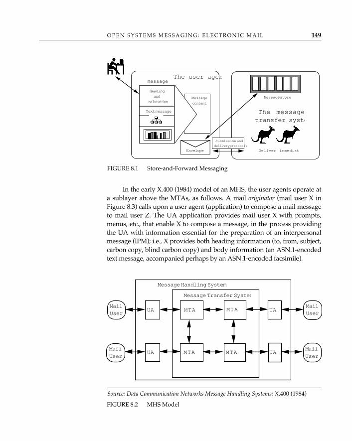
O P E N S Y S T E M S M E S S A G I N G : E L E C T R O N I C M A I L 149
In the early X.400 (1984) model of an MHS, the user agents operate ata sublayer above the MTAs, as follows. A mail originator (mail user X inFigure 8.3) calls upon a user agent (application) to compose a mail messageto mail user Z. The UA application provides mail user X with prompts,menus, etc., that enable X to compose a message, in the process providingthe UA with information essential for the preparation of an interpersonalmessage (IPM); i.e., X provides both heading information (to, from, subject,carbon copy, blind carbon copy) and body information (an ASN.1-encodedtext message, accompanied perhaps by an ASN.1-encoded facsimile).
FIGURE 8.1 Store-and-Forward Messaging
message
Text message
Headingand
salutationMessagecontent
Envelope
MessageThe user agen
Message store
The messagetransfer syste
Deliver immediat
Submission and
delivery protocols
FIGURE 8.2 MHS Model
MTA UA
MailUser
MailUser
MailUser
UAMailUser
MTA MTA
MTA
UAUA
Message Transfer System
Message Handling System
Source: Data Communication Networks Message Handling Systems: X.400 (1984)
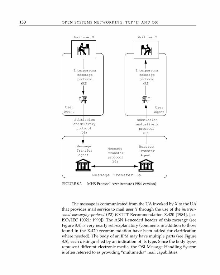
O P E N S Y S T E M S N E T W O R K I N G : T C P / I P A N D O S I150
The message is communicated from the UA invoked by X to the UAthat provides mail service to mail user Y through the use of the interper-sonal messaging protocol (P2) (CCITT Recommendation X.420 [1984], [seeISO/IEC 10021: 1990]). The ASN.1-encoded header of this message (seeFigure 8.4) is very nearly self-explanatory (comments in addition to thosefound in the X.420 recommendation have been added for clarificationwhere needed). The body of an IPM may have multiple parts (see Figure8.5), each distinguished by an indication of its type. Since the body typesrepresent different electronic media, the OSI Message Handling Systemis often referred to as providing “multimedia” mail capabilities.
Mail user Z
Interpersonamessageprotocol(P2)
UserAgent
MessageTransferAgent
Messagetransferprotocol(P1)
Message Transfer Sy
Mail user X
Interpersonamessageprotocol(P2)
UserAgent
Submissionand deliveryprotocol(P3)
Submissionand deliveryprotocol(P3)
MessageTransferAgent
FIGURE 8.3 MHS Protocol Architecture (1984 version)
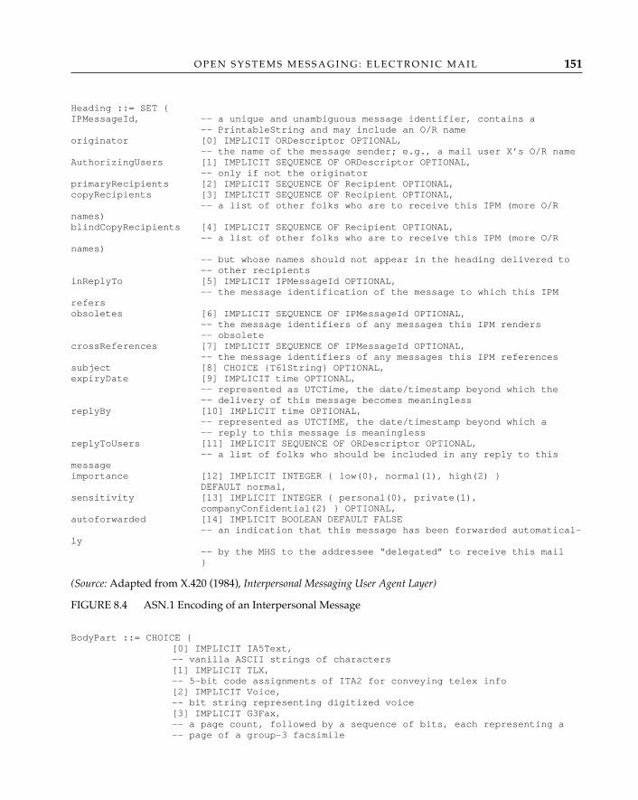
O P E N S Y S T E M S M E S S A G I N G : E L E C T R O N I C M A I L 151
Heading ::= SET {IPMessageId, -- a unique and unambiguous message identifier, contains a
-- PrintableString and may include an O/R nameoriginator [0] IMPLICIT ORDescriptor OPTIONAL,
-- the name of the message sender; e.g., a mail user X’s O/R nameAuthorizingUsers [1] IMPLICIT SEQUENCE OF ORDescriptor OPTIONAL,
-- only if not the originatorprimaryRecipients [2] IMPLICIT SEQUENCE OF Recipient OPTIONAL,copyRecipients [3] IMPLICIT SEQUENCE OF Recipient OPTIONAL,
-- a list of other folks who are to receive this IPM (more O/Rnames)blindCopyRecipients [4] IMPLICIT SEQUENCE OF Recipient OPTIONAL,
-- a list of other folks who are to receive this IPM (more O/Rnames)
-- but whose names should not appear in the heading delivered to-- other recipients
inReplyTo [5] IMPLICIT IPMessageId OPTIONAL,-- the message identification of the message to which this IPM
refersobsoletes [6] IMPLICIT SEQUENCE OF IPMessageId OPTIONAL,
-- the message identifiers of any messages this IPM renders -- obsolete
crossReferences [7] IMPLICIT SEQUENCE OF IPMessageId OPTIONAL,-- the message identifiers of any messages this IPM references
subject [8] CHOICE {T61String} OPTIONAL,expiryDate [9] IMPLICIT time OPTIONAL,
-- represented as UTCTime, the date/timestamp beyond which the-- delivery of this message becomes meaningless
replyBy [10] IMPLICIT time OPTIONAL,-- represented as UTCTIME, the date/timestamp beyond which a-- reply to this message is meaningless
replyToUsers [11] IMPLICIT SEQUENCE OF ORDescriptor OPTIONAL,-- a list of folks who should be included in any reply to this
messageimportance [12] IMPLICIT INTEGER { low(0), normal(1), high(2) }
DEFAULT normal,sensitivity [13] IMPLICIT INTEGER { personal(0), private(1),
companyConfidential(2) } OPTIONAL,autoforwarded [14] IMPLICIT BOOLEAN DEFAULT FALSE
-- an indication that this message has been forwarded automatical-ly
-- by the MHS to the addressee “delegated” to receive this mail}
(Source: Adapted from X.420 (1984), Interpersonal Messaging User Agent Layer)
FIGURE 8.4 ASN.1 Encoding of an Interpersonal Message
BodyPart ::= CHOICE {[0] IMPLICIT IA5Text,-- vanilla ASCII strings of characters[1] IMPLICIT TLX,-- 5-bit code assignments of ITA2 for conveying telex info[2] IMPLICIT Voice,-- bit string representing digitized voice[3] IMPLICIT G3Fax,-- a page count, followed by a sequence of bits, each representing a -- page of a group-3 facsimile

O P E N S Y S T E M S N E T W O R K I N G : T C P / I P A N D O S I152
[4] IMPLICIT TIF0,-- a document encoded according to T.73 text-interchange format-- (used by group-4 fax class-1 terminals)[5] IMPLICIT TTX,-- body part is a teletex document (sequence of T61 charstrings)[6] IMPLICIT Videotex,-- body part is a videotex document (T.100- or T.101-encoded)[7] NationallyDefined,[8] IMPLICIT Encrypted,-- a body part that has been subjected to encryption[9] IMPLICIT ForwardedIPMessage,-- a body part where an IPM has been subsumed within an IPM[10] IMPLICIT SFD,-- character-encoded information organized as a sequence of -- paragraphs, the details of which are specified in CCITT -- Recommendation X.420, called a “simple formatted document”[11] IMPLICIT TIF1-- a document encoded according to T.73 text-interchange format-- (used by group-4 fax class-2 and -3 terminals)}
(Source: Adapted from X.420 (1984), Interpersonal Messaging User Agent Layer)
FIGURE 8.5 IPM Body Types
Continuing with the example in Figure 8.3, the UA invoked by mailuser X logs onto a message transfer agent and submits the interpersonalmessage through a series of service requests. Using the abstract LOGONservice, the user agent provides the MTA with the name of the mail origi-nator and a password to validate the UA. (In some electronic-mail appli-cations, the end user provides log-on information once, at applicationstart-up.) Once validated, the user agent invokes the message-submissionservice (SUBMIT) to transfer messages to one or more recipients. In prac-tice, the detailed operation of the message-submission service is hiddenfrom the end user. Although user interfaces differ across E-mail applica-tions, many offer a menu of mail-creation operations (create new message,forward message, reply to message, attach file); once a message is com-posed, the user may queue it for submission or send it immediately, oftenby the simple act of hitting a “send” key or clicking on an equivalent “but-ton.” The E-mail application composes the information needed to submitthe message to the message transfer system for the mail user (recipient,message content and content type, options such as deferred delivery time,priority, and delivery notice). If the MTA is remote from the UA—i.e., theUA cannot communicate with the MTA via a local (Interprocess commu-nication) interface—the interpersonal message is forwarded to the MTAin a submissionEnvelope, one of a set of message protocol data units
2. At the time of publication of the X.400 (1984) Recommendations, the application-
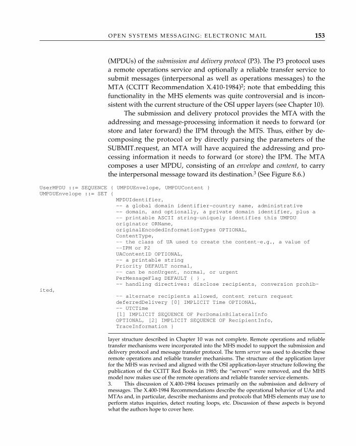
O P E N S Y S T E M S M E S S A G I N G : E L E C T R O N I C M A I L 153
(MPDUs) of the submission and delivery protocol (P3). The P3 protocol usesa remote operations service and optionally a reliable transfer service tosubmit messages (interpersonal as well as operations messages) to theMTA (CCITT Recommendation X.410-1984)2; note that embedding thisfunctionality in the MHS elements was quite controversial and is incon-sistent with the current structure of the OSI upper layers (see Chapter 10).
The submission and delivery protocol provides the MTA with theaddressing and message-processing information it needs to forward (orstore and later forward) the IPM through the MTS. Thus, either by de-composing the protocol or by directly parsing the parameters of theSUBMIT.request, an MTA will have acquired the addressing and pro-cessing information it needs to forward (or store) the IPM. The MTAcomposes a user MPDU, consisting of an envelope and content, to carrythe interpersonal message toward its destination.3 (See Figure 8.6.)
UserMPDU ::= SEQUENCE { UMPDUEnvelope, UMPDUContent }UMPDUEnvelope ::= SET {
MPDUIdentifier,-- a global domain identifier—country name, administrative -- domain, and optionally, a private domain identifier, plus a-- printable ASCII string—uniquely identifies this UMPDUoriginator ORName,originalEncodedInformationTypes OPTIONAL,ContentType,-- the class of UA used to create the content—e.g., a value of --IPM or P2UAContentID OPTIONAL,-- a printable stringPriority DEFAULT normal,-- can be nonUrgent, normal, or urgentPerMessageFlag DEFAULT { } ,-- handling directives: disclose recipients, conversion prohib-
ited, -- alternate recipients allowed, content return requestdeferredDelivery [0] IMPLICIT Time OPTIONAL,-- UTCTime[1] IMPLICIT SEQUENCE OF PerDomainBilateralInfo OPTIONAL, [2] IMPLICIT SEQUENCE OF RecipientInfo, TraceInformation }
layer structure described in Chapter 10 was not complete. Remote operations and reliabletransfer mechanisms were incorporated into the MHS model to support the submission anddelivery protocol and message transfer protocol. The term server was used to describe theseremote operations and reliable transfer mechanisms. The structure of the application layerfor the MHS was revised and aligned with the OSI application-layer structure following thepublication of the CCITT Red Books in 1985; the “servers” were removed, and the MHSmodel now makes use of the remote operations and reliable transfer service elements.3. This discussion of X.400-1984 focuses primarily on the submission and delivery ofmessages. The X.400-1984 Recommendations describe the operational behavior of UAs andMTAs and, in particular, describe mechanisms and protocols that MHS elements may use toperform status inquiries, detect routing loops, etc. Discussion of these aspects is beyondwhat the authors hope to cover here.
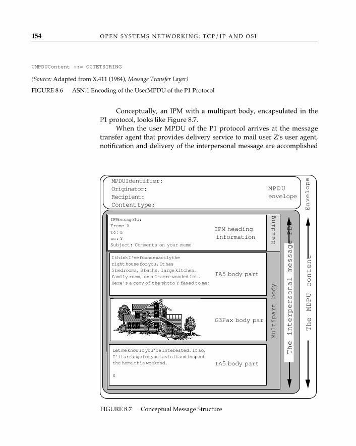
O P E N S Y S T E M S N E T W O R K I N G : T C P / I P A N D O S I154
UMPDUContent ::= OCTETSTRING
(Source: Adapted from X.411 (1984), Message Transfer Layer)
FIGURE 8.6 ASN.1 Encoding of the UserMPDU of the P1 Protocol
Conceptually, an IPM with a multipart body, encapsulated in theP1 protocol, looks like Figure 8.7.
When the user MPDU of the P1 protocol arrives at the messagetransfer agent that provides delivery service to mail user Z’s user agent,notification and delivery of the interpersonal message are accomplished
FIGURE 8.7 Conceptual Message Structure
IPMessageId:
From: X
To: Z
cc: Y
Subject: Comments on your memo
IPM headinginformation
IA5 body part
I think I've found exactly the
right house for you. It has
5 bedrooms, 3 baths, large kitchen,
family room, on a 1-acre wooded lot.
Here's a copy of the photo Y faxed to me:
G3Fax body part
IA5 body part
Let me know if you're interested. If so,
I'll arrange for you to visit and inspect
the home this weekend.
�
X
Multipart body
MPDUIdentifier:Originator:Recipient:Content type:
Heading
The interpersonal message PDU
MPDUenvelope
The MDPU content
Envelope
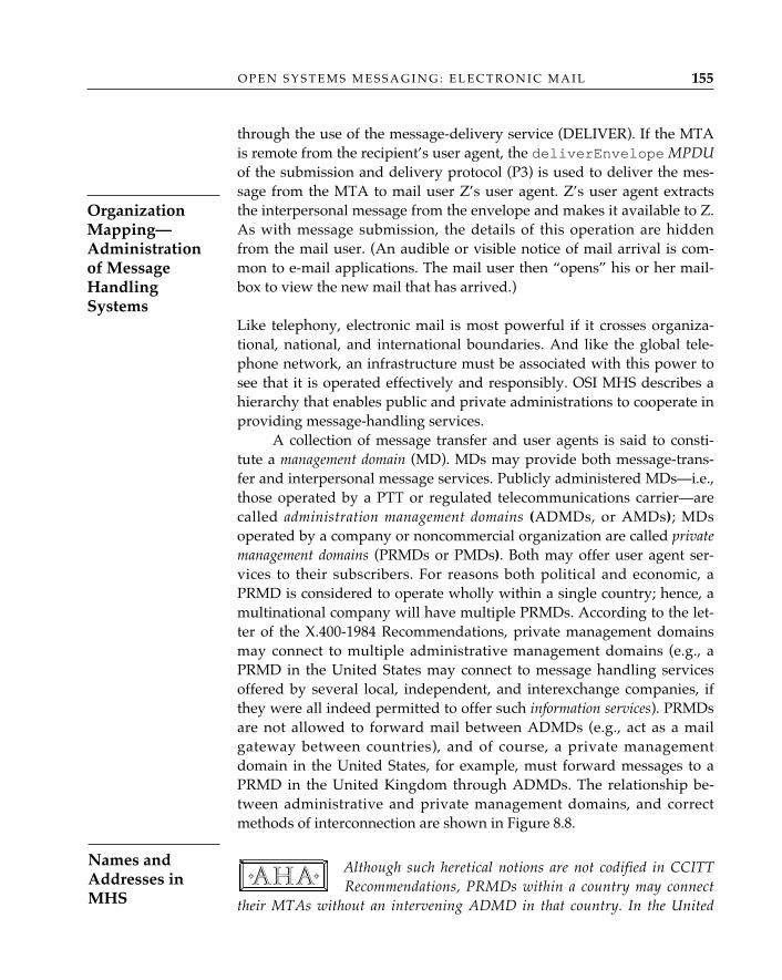
through the use of the message-delivery service (DELIVER). If the MTAis remote from the recipient’s user agent, the deliverEnvelope MPDUof the submission and delivery protocol (P3) is used to deliver the mes-sage from the MTA to mail user Z’s user agent. Z’s user agent extractsthe interpersonal message from the envelope and makes it available to Z.As with message submission, the details of this operation are hiddenfrom the mail user. (An audible or visible notice of mail arrival is com-mon to e-mail applications. The mail user then “opens” his or her mail-box to view the new mail that has arrived.)
Like telephony, electronic mail is most powerful if it crosses organiza-tional, national, and international boundaries. And like the global tele-phone network, an infrastructure must be associated with this power tosee that it is operated effectively and responsibly. OSI MHS describes ahierarchy that enables public and private administrations to cooperate inproviding message-handling services.
A collection of message transfer and user agents is said to consti-tute a management domain (MD). MDs may provide both message-trans-fer and interpersonal message services. Publicly administered MDs—i.e.,those operated by a PTT or regulated telecommunications carrier—arecalled administration management domains (ADMDs, or AMDs); MDsoperated by a company or noncommercial organization are called privatemanagement domains (PRMDs or PMDs). Both may offer user agent ser-vices to their subscribers. For reasons both political and economic, aPRMD is considered to operate wholly within a single country; hence, amultinational company will have multiple PRMDs. According to the let-ter of the X.400-1984 Recommendations, private management domainsmay connect to multiple administrative management domains (e.g., aPRMD in the United States may connect to message handling servicesoffered by several local, independent, and interexchange companies, ifthey were all indeed permitted to offer such information services). PRMDsare not allowed to forward mail between ADMDs (e.g., act as a mailgateway between countries), and of course, a private managementdomain in the United States, for example, must forward messages to aPRMD in the United Kingdom through ADMDs. The relationship be-tween administrative and private management domains, and correctmethods of interconnection are shown in Figure 8.8.
Although such heretical notions are not codified in CCITTRecommendations, PRMDs within a country may connect
their MTAs without an intervening ADMD in that country. In the United
✧AHA✧
O P E N S Y S T E M S M E S S A G I N G : E L E C T R O N I C M A I L 155
OrganizationMapping—Administrationof MessageHandlingSystems
Names andAddresses inMHS
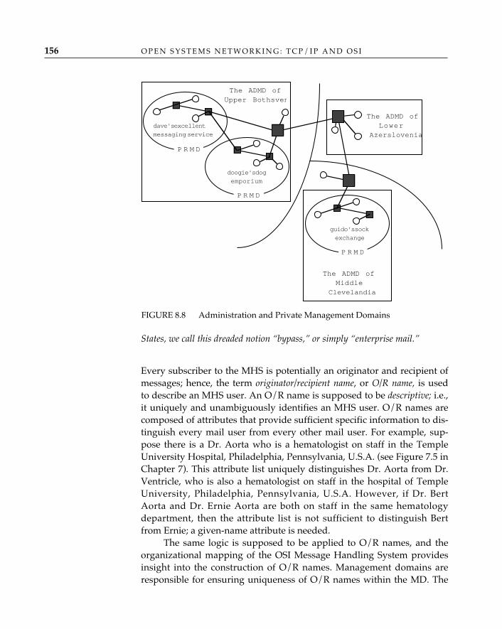
O P E N S Y S T E M S N E T W O R K I N G : T C P / I P A N D O S I156
States, we call this dreaded notion “bypass,” or simply “enterprise mail.”
Every subscriber to the MHS is potentially an originator and recipient ofmessages; hence, the term originator/recipient name, or O/R name, is usedto describe an MHS user. An O/R name is supposed to be descriptive; i.e.,it uniquely and unambiguously identifies an MHS user. O/R names arecomposed of attributes that provide sufficient specific information to dis-tinguish every mail user from every other mail user. For example, sup-pose there is a Dr. Aorta who is a hematologist on staff in the TempleUniversity Hospital, Philadelphia, Pennsylvania, U.S.A. (see Figure 7.5 inChapter 7). This attribute list uniquely distinguishes Dr. Aorta from Dr.Ventricle, who is also a hematologist on staff in the hospital of TempleUniversity, Philadelphia, Pennsylvania, U.S.A. However, if Dr. BertAorta and Dr. Ernie Aorta are both on staff in the same hematologydepartment, then the attribute list is not sufficient to distinguish Bertfrom Ernie; a given-name attribute is needed.
The same logic is supposed to be applied to O/R names, and theorganizational mapping of the OSI Message Handling System providesinsight into the construction of O/R names. Management domains areresponsible for ensuring uniqueness of O/R names within the MD. The
FIGURE 8.8 Administration and Private Management Domains
doogie's dog
emporium
P R M D
dave's excellent
messaging service
P R M D
The ADMD ofUpper Bothsven
The ADMD ofMiddle
Clevelandia
The ADMD ofLower
Azerslovenia
guido's sock
exchange
P R M D
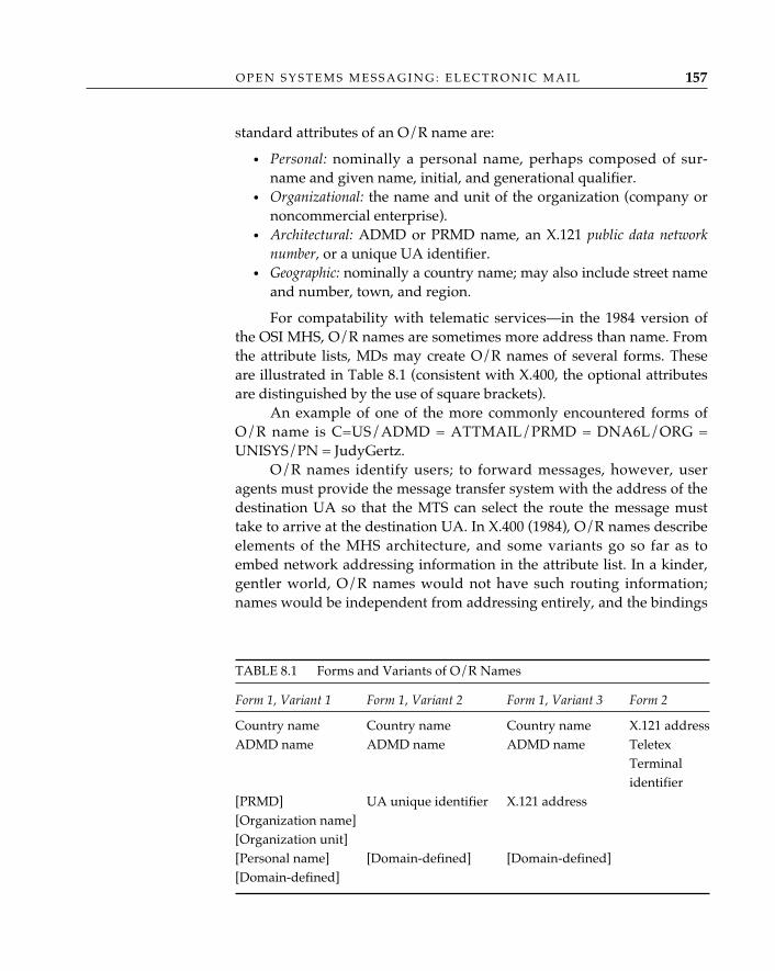
standard attributes of an O/R name are:
• Personal: nominally a personal name, perhaps composed of sur-name and given name, initial, and generational qualifier.
• Organizational: the name and unit of the organization (company ornoncommercial enterprise).
• Architectural: ADMD or PRMD name, an X.121 public data networknumber, or a unique UA identifier.
• Geographic: nominally a country name; may also include street nameand number, town, and region.
For compatability with telematic services—in the 1984 version ofthe OSI MHS, O/R names are sometimes more address than name. Fromthe attribute lists, MDs may create O/R names of several forms. Theseare illustrated in Table 8.1 (consistent with X.400, the optional attributesare distinguished by the use of square brackets).
An example of one of the more commonly encountered forms ofO/R name is C=US/ADMD = ATTMAIL/PRMD = DNA6L/ORG =UNISYS/PN = JudyGertz.
O/R names identify users; to forward messages, however, useragents must provide the message transfer system with the address of thedestination UA so that the MTS can select the route the message musttake to arrive at the destination UA. In X.400 (1984), O/R names describeelements of the MHS architecture, and some variants go so far as toembed network addressing information in the attribute list. In a kinder,gentler world, O/R names would not have such routing information;names would be independent from addressing entirely, and the bindings
O P E N S Y S T E M S M E S S A G I N G : E L E C T R O N I C M A I L 157
TABLE 8.1 Forms and Variants of O/R Names
Form 1, Variant 1 Form 1, Variant 2 Form 1, Variant 3 Form 2
Country name Country name Country name X.121 addressADMD name ADMD name ADMD name Teletex
Terminal identifier
[PRMD] UA unique identifier X.121 address[Organization name][Organization unit][Personal name] [Domain-defined] [Domain-defined][Domain-defined]
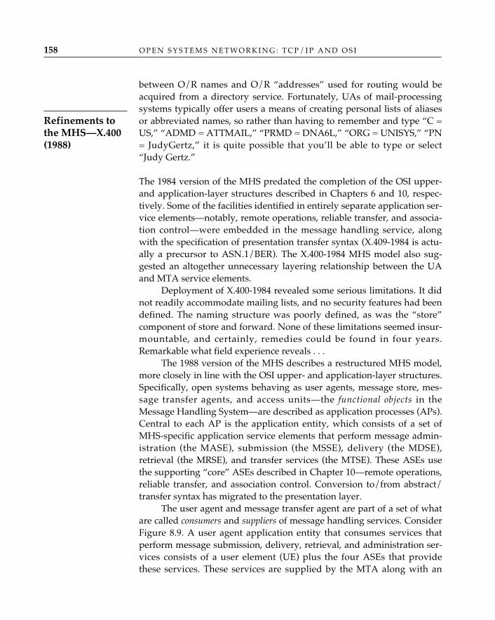
O P E N S Y S T E M S N E T W O R K I N G : T C P / I P A N D O S I158
between O/R names and O/R “addresses” used for routing would beacquired from a directory service. Fortunately, UAs of mail-processingsystems typically offer users a means of creating personal lists of aliasesor abbreviated names, so rather than having to remember and type “C =US,” “ADMD = ATTMAIL,” “PRMD = DNA6L,” “ORG = UNISYS,” “PN= JudyGertz,” it is quite possible that you’ll be able to type or select“Judy Gertz.”
The 1984 version of the MHS predated the completion of the OSI upper-and application-layer structures described in Chapters 6 and 10, respec-tively. Some of the facilities identified in entirely separate application ser-vice elements—notably, remote operations, reliable transfer, and associa-tion control—were embedded in the message handling service, alongwith the specification of presentation transfer syntax (X.409-1984 is actu-ally a precursor to ASN.1/BER). The X.400-1984 MHS model also sug-gested an altogether unnecessary layering relationship between the UAand MTA service elements.
Deployment of X.400-1984 revealed some serious limitations. It didnot readily accommodate mailing lists, and no security features had beendefined. The naming structure was poorly defined, as was the “store”component of store and forward. None of these limitations seemed insur-mountable, and certainly, remedies could be found in four years.Remarkable what field experience reveals . . .
The 1988 version of the MHS describes a restructured MHS model,more closely in line with the OSI upper- and application-layer structures.Specifically, open systems behaving as user agents, message store, mes-sage transfer agents, and access units—the functional objects in theMessage Handling System—are described as application processes (APs).Central to each AP is the application entity, which consists of a set ofMHS-specific application service elements that perform message admin-istration (the MASE), submission (the MSSE), delivery (the MDSE),retrieval (the MRSE), and transfer services (the MTSE). These ASEs usethe supporting “core” ASEs described in Chapter 10—remote operations,reliable transfer, and association control. Conversion to/from abstract/transfer syntax has migrated to the presentation layer.
The user agent and message transfer agent are part of a set of whatare called consumers and suppliers of message handling services. ConsiderFigure 8.9. A user agent application entity that consumes services thatperform message submission, delivery, retrieval, and administration ser-vices consists of a user element (UE) plus the four ASEs that providethese services. These services are supplied by the MTA along with an
Refinements tothe MHS—X.400(1988)
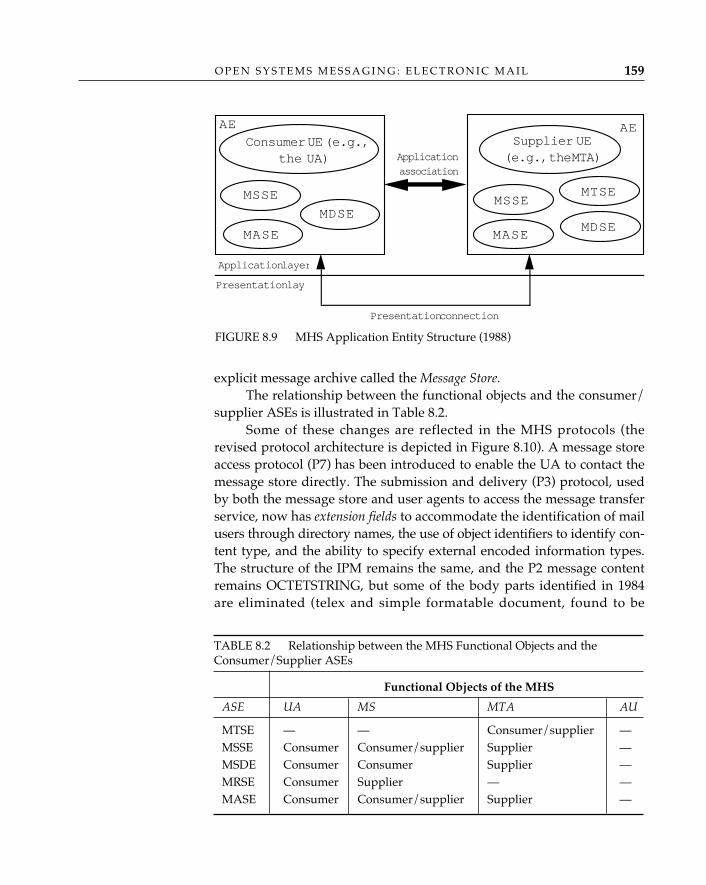
O P E N S Y S T E M S M E S S A G I N G : E L E C T R O N I C M A I L 159
explicit message archive called the Message Store.The relationship between the functional objects and the consumer/
supplier ASEs is illustrated in Table 8.2.Some of these changes are reflected in the MHS protocols (the
revised protocol architecture is depicted in Figure 8.10). A message storeaccess protocol (P7) has been introduced to enable the UA to contact themessage store directly. The submission and delivery (P3) protocol, usedby both the message store and user agents to access the message transferservice, now has extension fields to accommodate the identification of mailusers through directory names, the use of object identifiers to identify con-tent type, and the ability to specify external encoded information types.The structure of the IPM remains the same, and the P2 message contentremains OCTETSTRING, but some of the body parts identified in 1984are eliminated (telex and simple formatable document, found to be
FIGURE 8.9 MHS Application Entity Structure (1988)
Consumer UE (e.g.,the UA)
MSSE
MDSE
MASE
Supplier UE(e.g., the MTA)
MSSE
MDSE
MTSE
MASE
Applicationassociation
Application layer
Presentation lay
Presentation connection
AE AE
TABLE 8.2 Relationship between the MHS Functional Objects and theConsumer/Supplier ASEs
Functional Objects of the MHS
ASE UA MS MTA AU
MTSE — — Consumer/supplier —MSSE Consumer Consumer/supplier Supplier —MSDE Consumer Consumer Supplier —MRSE Consumer Supplier — —MASE Consumer Consumer/supplier Supplier —
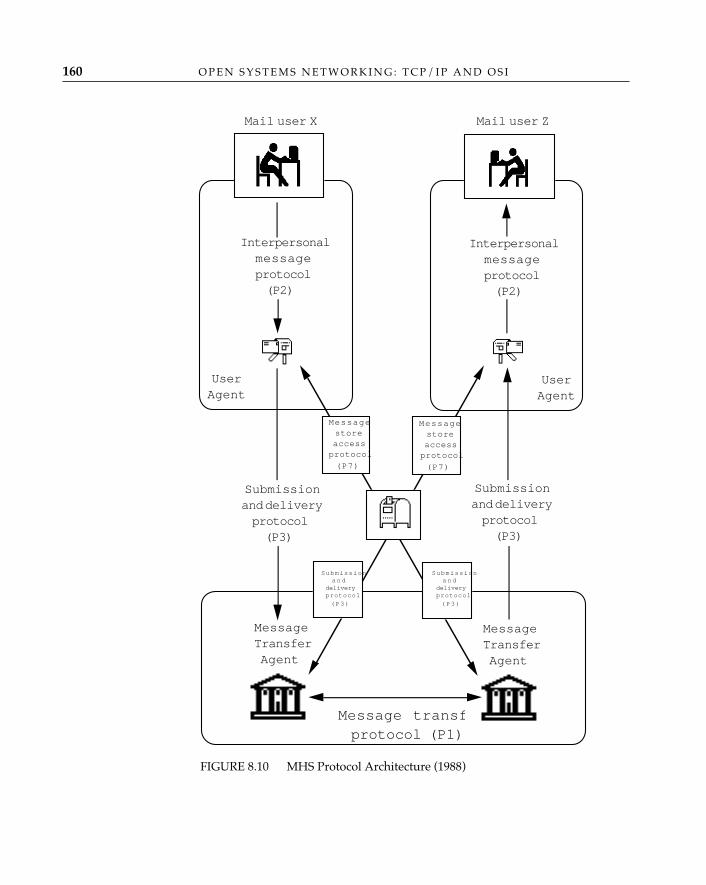
O P E N S Y S T E M S N E T W O R K I N G : T C P / I P A N D O S I160
Mail user Z
Interpersonalmessageprotocol(P2)
UserAgent
Mail user X
Interpersonalmessageprotocol(P2)
UserAgent
Submissionand deliveryprotocol(P3)
Submissionand deliveryprotocol(P3)
MessageTransferAgent
Message transfprotocol (P1)
MessageTransferAgent
Messagestoreaccessprotocol
(P7)
Messagestoreaccessprotocol
(P7)
Submissionand
deliveryprotocol
(P3)
Submissionand
deliveryprotocol
(P3)
FIGURE 8.10 MHS Protocol Architecture (1988)
O P E N S Y S T E M S M E S S A G I N G : E L E C T R O N I C M A I L 161
redundant). A new value for the content type (22) is defined to distin-guish X.420-1988–encoded contents from ones that are entirely consistentwith content types that might have been generated using X.420-1984. (Insuch cases, the value of this data type remains 2.)
X.400-1988 introduces new functionality as well. It is now possibleto create distribution lists and, within this context, closed user groups.Distribution lists provide mail users with the ability to send messages toa group of mail users using a single O/R name (which is the name of thelist). A mail user who is authorized to send mail to a distribution listsends a single message to the distribution-list O/R name; the messagetransfer system sees that a copy of this message is forwarded to all mem-bers of the list (this process is called expansion). Typically, a single usermanages the distribution list and is responsible for adding members toand removing members from the list. The distribution list identifies therecipients of messages but imposes no restrictions on who may post mes-sages to the distribution-list O/R name, once that name is discovered bya nonmember. An administrator of a distribution list may also limit whois allowed to send messages to that list (the constituency of who maypost messages to a distribution list is called a closed user group).
X.400-1988 provides a means of introducing privacy to electronicmail. Using the security mechanisms developed for the X.500 Directory, apublic-key encryption system can be used to generate an electronic signa-ture. The means of decoding the signature are understood only by thecommunicating parties and the public-key administrator. With the signa-ture, a recipient can, for example, authenticate the origin of a message,verify the integrity of the message content, and authenticate the messagepartner (peer). Using mechanisms also recommended in X.509, a messagecan be encrypted and thus kept confidential. (A thorough discussion ofthe security aspects of X.400-1988 is provided in Plattner et al. 1991.)
X.400-1988 introduces the use of X.500 directory names as a complemen-tary way of identifying mail users (O/R names as composed in X.400-1984 can still be used). Directory distinguished names, which can beentirely free of “addressing” attributes, can be used by the UA to accessthe MS or MTA, and between the MS and an MTA as well; for routingbetween MTAs, however, a directory name-to-UA address mappingmust be performed. Specifically, either the user agent of the originator ofa message or the first message transfer agent on the path from the origi-nator to the recipient must perform the directory name to O/R addressmapping by querying the OSI Directory whenever the originator uses adirectory name rather than an O/R address. Such mappings can be regis-
MHS and theDirectory
tered in the OSI Directory by the administrator of a managementdomain; thereafter, MTAs may search the OSI Directory for the name-address mapping. The name-to-address mappings may also be modifiedby an administrator if, for example, a mail user moves from one manage-ment domain to another. If directory naming is done independently ofUA addressing, the migration of the mail user from one managementdomain to another is entirely transparent to all other mail users.
Message Handling System use of the OSI Directory is not limited toname-address resolution. MHS elements may use the OSI Directory toexpand distribution lists (i.e., to obtain the UA addresses of all the UAsthat provide service to members of the list) and to learn what servicesand functions MHS components support.
In configurations in which an MTA is remote from a UA, the submission anddelivery protocol (P3) provides the means by which an MTA and the useragent accomplish what would otherwise be signaled across a local interface,perhaps in something as simple as a procedure call; i.e., the UA invokes oper-ations at the MTA (literally “store and forward the message”), and similarly,the MTA delivers messages to the UA (deliver it to the user). In OSI, proce-dure calls that are performed across a distributed interface (i.e., across an OSIconnection between two applications) are called remote operations.
Interpersonal messages containing graphic, digitized voice, or fac-simile body parts can be quite large. Generally speaking, if communicationbetween UAs and MTAs is disrupted during the transfer of a large mes-sage, restarting from the beginning of the message is time-consuming and,in some cases, expensive. For such messages, the ability to provide check-points during message transfer so that UAs and MTAs can recover from(temporary) communications failures, resynchronize to a common point torestart, and continue from that point with a minimum amount of retrans-mission is an important aspect of message forwarding and delivery. In OSIthis is called reliable transfer. OSI provides both reliable transfer and remoteoperations capabilities as part of the communications toolbox described inChapter 10, ‘Core’ Application Service Elements. In the 1984 version of theMHS, remote operations and reliable transfer were embedded in X.400(1988), the MHS application service elements make use of the remote oper-ations and reliable transfer services provided by the core ASEs to operatethe MHS protocols.
By the time the 1988 version of MHS was available, a modest but grow-
O P E N S Y S T E M S N E T W O R K I N G : T C P / I P A N D O S I162
MHS Use ofRemoteOperations andReliable TransferFacilities
Interworkingbetween X.400(1984) and X.400(1988)
4. The mechanisms to assist in negotiating the correct OSI upper layer protocol envi-ronment are described in Chapter 10.
O P E N S Y S T E M S M E S S A G I N G : E L E C T R O N I C M A I L 163
ing installed base of 1984 implementations existed. Eventually, these willgo away. However, with the extensions to the MHS and protocols, withthe introduction of new naming conventions, and in particular, with theconsiderable modifications to the OSI upper layers over which MHSwould operate, a fair number of incompatibilities exist.4
From the perspective of the 1988 MHS user, interconnecting 1988and 1984 MHS implementations is a process, however temporary, oflowering one’s expectations and is called downgrading. The extensionsintroduced in the 1988 version were done so that the MHS would runwithout them (they are encoded as additional elements of protocol).X.419-1988 Appendix B notes that unless the extension is marked as criti-cal for transfer or critical for delivery, it can simply be deleted; other-wise, “downgrading” cannot be performed, and message forwarding/delivery will fail. (A particularly disappointing aspect of downgrading isthat it prevents the use of the security features.) Directory names cannotbe used, and X.419-1988 suggests that downgrading be accomplished bydeleting the directory name and the O/R address. The Internet commu-nity has spent considerable time and effort piloting the use of X.400 andhas some practical solutions to dealing with “downgrading.” As a gener-al approach, RFC 1328 suggests the use of a domain-defined attribute,always a standard O/R name as defined in RFC 1327.
RFC 1328 also suggests several alternatives that may be appliedwhen dealing with the issue of downgrading interpersonal messages.Depending on gateways and their configuration, it will in some cases benecessary to downgrade from an X.400-1988 content type to one con-forming to X.400-1984. In such circumstances, only protocol controlinformation and addressing that can be parsed by a 1984 MHS imple-mentation can remain in the IPM that is to be forwarded. Body-part con-version is another story. Five scenarios exist:
• Some of the information encoded in the 1988 body part is lost.• The 1988 body part is converted without loss (not always in the “a
miracle occurs” category, but close).• Conversion is simply not possible, and the message must be dis-
carded.• The body part can be discarded and replaced with a (typically IA5
text) message.• The body part can be encapsulated as an external 1984 body part.
Although these scenarios paint a somewhat bleak picture whendowngrading, the net effect is more positive. Mail users on 1984 MHSmay still exchange primarily textual messages with 1988 MHS mailusers. The bottom line on downgrading: avoid it if possible.
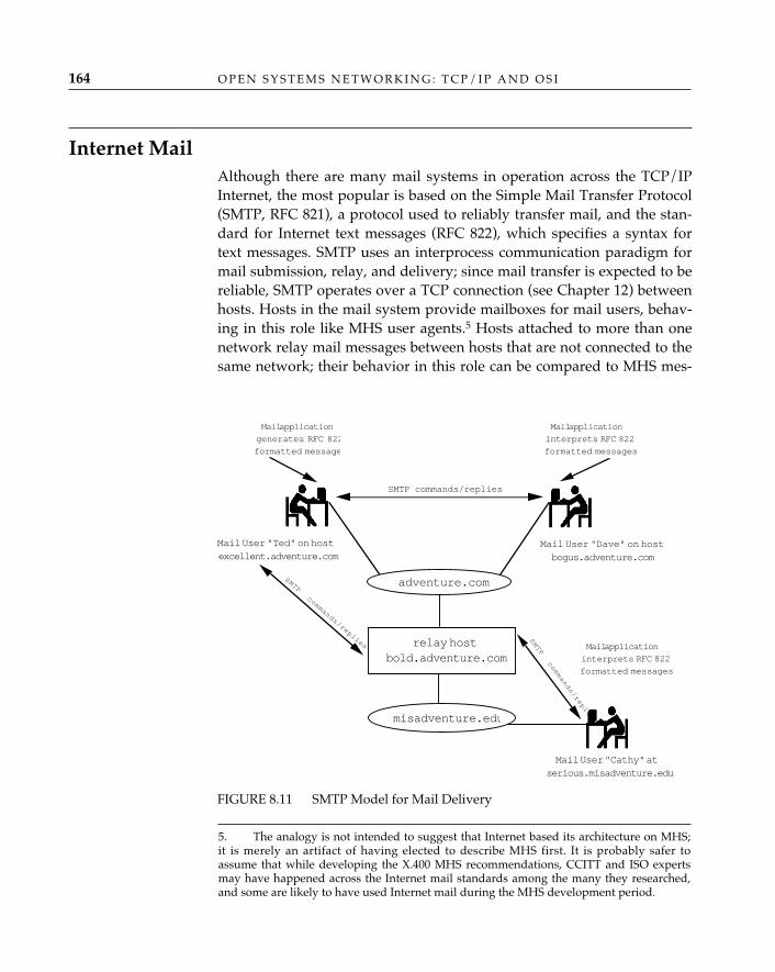
O P E N S Y S T E M S N E T W O R K I N G : T C P / I P A N D O S I164
Internet MailAlthough there are many mail systems in operation across the TCP/IPInternet, the most popular is based on the Simple Mail Transfer Protocol(SMTP, RFC 821), a protocol used to reliably transfer mail, and the stan-dard for Internet text messages (RFC 822), which specifies a syntax fortext messages. SMTP uses an interprocess communication paradigm formail submission, relay, and delivery; since mail transfer is expected to bereliable, SMTP operates over a TCP connection (see Chapter 12) betweenhosts. Hosts in the mail system provide mailboxes for mail users, behav-ing in this role like MHS user agents.5 Hosts attached to more than onenetwork relay mail messages between hosts that are not connected to thesame network; their behavior in this role can be compared to MHS mes-
5. The analogy is not intended to suggest that Internet based its architecture on MHS;it is merely an artifact of having elected to describe MHS first. It is probably safer toassume that while developing the X.400 MHS recommendations, CCITT and ISO expertsmay have happened across the Internet mail standards among the many they researched,and some are likely to have used Internet mail during the MHS development period.
FIGURE 8.11 SMTP Model for Mail Delivery
Mail User "Ted" on hostexcellent.adventure.com
Mail application
generates RFC 822
formatted message
Mail User "Dave" on hostbogus.adventure.com
SMTP commands/replies
Mail application
interprets RFC 822
formatted messages
adventure.com
relay hostbold.adventure.com
misadventure.edu
SMTP commands/replies
SMTP commands/replies
Mail application
interprets RFC 822
formatted messages
Mail User "Cathy" atserious.misadventure.edu
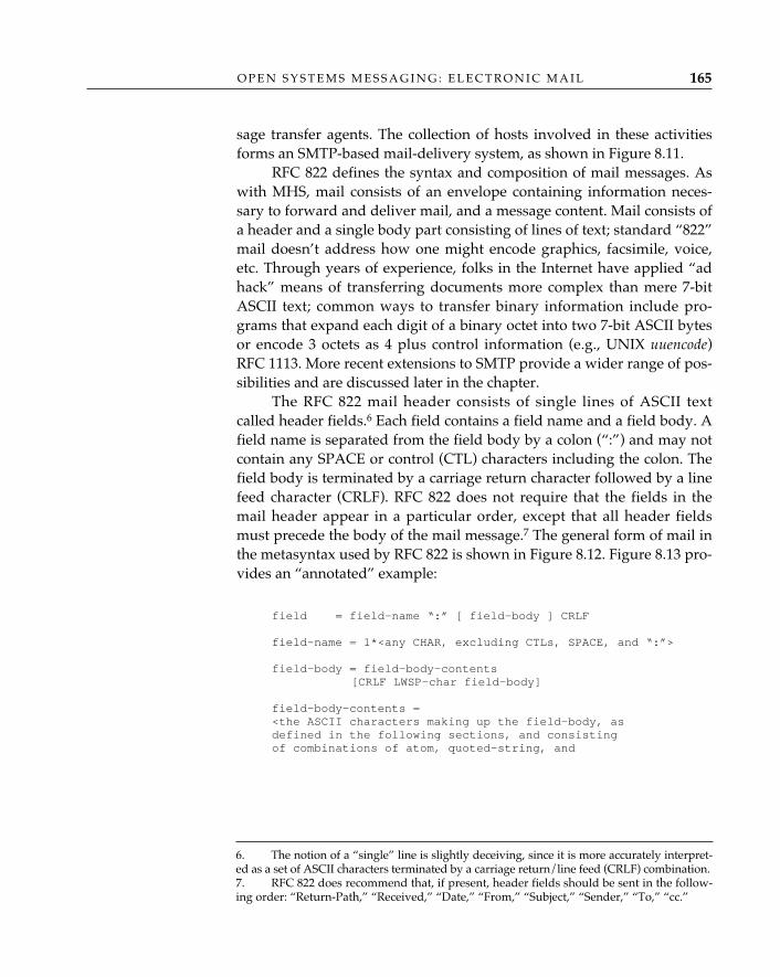
O P E N S Y S T E M S M E S S A G I N G : E L E C T R O N I C M A I L 165
sage transfer agents. The collection of hosts involved in these activitiesforms an SMTP-based mail-delivery system, as shown in Figure 8.11.
RFC 822 defines the syntax and composition of mail messages. Aswith MHS, mail consists of an envelope containing information neces-sary to forward and deliver mail, and a message content. Mail consists ofa header and a single body part consisting of lines of text; standard “822”mail doesn’t address how one might encode graphics, facsimile, voice,etc. Through years of experience, folks in the Internet have applied “adhack” means of transferring documents more complex than mere 7-bitASCII text; common ways to transfer binary information include pro-grams that expand each digit of a binary octet into two 7-bit ASCII bytesor encode 3 octets as 4 plus control information (e.g., UNIX uuencode)RFC 1113. More recent extensions to SMTP provide a wider range of pos-sibilities and are discussed later in the chapter.
The RFC 822 mail header consists of single lines of ASCII textcalled header fields.6 Each field contains a field name and a field body. Afield name is separated from the field body by a colon (“:”) and may notcontain any SPACE or control (CTL) characters including the colon. Thefield body is terminated by a carriage return character followed by a linefeed character (CRLF). RFC 822 does not require that the fields in themail header appear in a particular order, except that all header fieldsmust precede the body of the mail message.7 The general form of mail inthe metasyntax used by RFC 822 is shown in Figure 8.12. Figure 8.13 pro-vides an “annotated” example:
field = field-name “:” [ field-body ] CRLF
field-name = 1*<any CHAR, excluding CTLs, SPACE, and “:”>
field-body = field-body-contents[CRLF LWSP-char field-body]
field-body-contents =<the ASCII characters making up the field-body, asdefined in the following sections, and consistingof combinations of atom, quoted-string, and
6. The notion of a “single” line is slightly deceiving, since it is more accurately interpret-ed as a set of ASCII characters terminated by a carriage return/line feed (CRLF) combination.7. RFC 822 does recommend that, if present, header fields should be sent in the follow-ing order: “Return-Path,” “Received,” “Date,” “From,” “Subject,” “Sender,” “To,” “cc.”
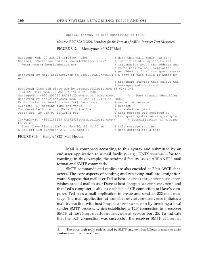
O P E N S Y S T E M S N E T W O R K I N G : T C P / I P A N D O S I166
special tokens, or else consisting of text>
(Source: RFC 822 (1982), Standard for the Format of ARPA Internet Text Messages)
FIGURE 8.12 Metasyntax of “822” Mail
Replied: Wed, 20 Jan 93 16:16:04 -0500 % date this mail reply was sentReplied: “Christine Hemrick <[email protected]>” % identifies who replied to mailReturn-Path: [email protected] % information about the address and
% route back to mail originator,% provided by final transport system
Received: by mail.bellcore.com;id 9301202023.AA05391 % a copy of this field is added byeach
% transport service that relays the% message—used for trace
Received: from ash.cisco.com by breeze.bellcore.com (5.61/1.34)id AA06912; Wed, 20 Jan 93 15:20:49 -0500
Message-Id: <[email protected]>. % unique message identifierReceived: by ash.cisco.com; Wed, 20 Jan 93 12:20:44 -0800From: Christine Hemrick <[email protected]> % sender of messageSubject: RE: meeting time and venue % subjectTo: [email protected] (Dave Piscitello) % intended recipientDate: Wed, 20 Jan 93 12:20:43 PST % time message was received by
% transport system serving recipientIn-Reply-To: <[email protected]>; % identification of messageto which from “Dave Piscitello” at Jan 20, 93 11:25 am % this message replies
X-Mailer: ELM [version 2.2 PL16 mips 1] % user-defined field name
FIGURE 8.13 Sample “822” Mail Header
Mail is composed according to this syntax and submitted by anend-user application to a mail facilitiy—e.g., UNIX sendmail—for for-warding; in this example, the sendmail facility uses “ARPANET” mailformat and SMTP commands.
SMTP commands and replies are also encoded as 7-bit ASCII char-acters. The core aspects of sending and receiving mail are straightfor-ward. Suppose that mail user Ted at host “excellent.adventure.com”wishes to send mail to user Dave at host “bogus.adventure.com” andthat Ted’s computer is able to establish a TCP connection to Dave’s com-puter. Ted uses a mail application to create and send an 822 mail mes-sage. The mail application at excellent.adventure.com initiates amail transaction with host bogus.adventure.com by invoking a localsender SMTP process, which establishes a TCP connection to a receiverSMTP at host bogus.adventure.com at service port 25. To indicatethat the TCP connection was successful, the receiver SMTP at bogus.
8. The three-digit reply code is used by SMTP; any text that follows is meant to assistpostmasters . . . or humor them.
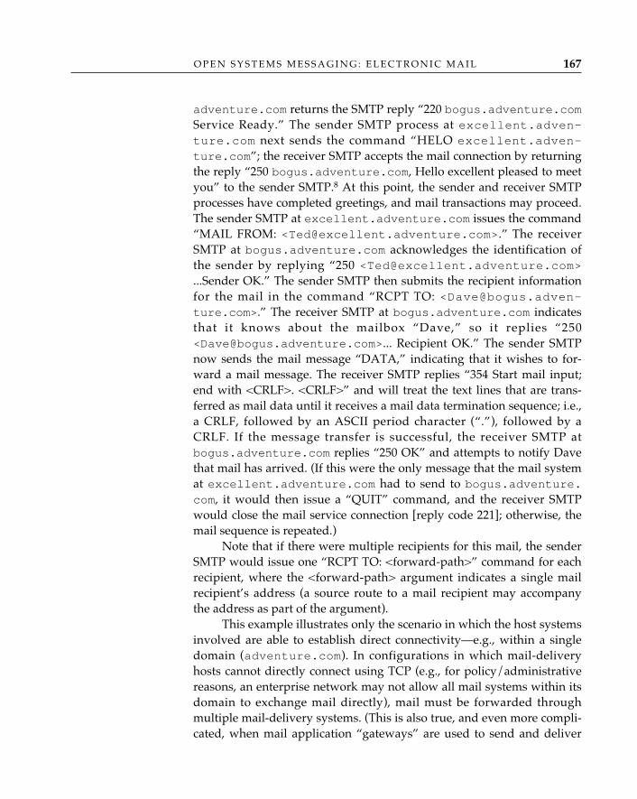
O P E N S Y S T E M S M E S S A G I N G : E L E C T R O N I C M A I L 167
adventure.com returns the SMTP reply “220 bogus.adventure.comService Ready.” The sender SMTP process at excellent.adven-ture.com next sends the command “HELO excellent.adven-ture.com”; the receiver SMTP accepts the mail connection by returningthe reply “250 bogus.adventure.com, Hello excellent pleased to meetyou” to the sender SMTP.8 At this point, the sender and receiver SMTPprocesses have completed greetings, and mail transactions may proceed.The sender SMTP at excellent.adventure.com issues the command“MAIL FROM: <[email protected]>.” The receiverSMTP at bogus.adventure.com acknowledges the identification ofthe sender by replying “250 <[email protected]>...Sender OK.” The sender SMTP then submits the recipient informationfor the mail in the command “RCPT TO: <[email protected]>.” The receiver SMTP at bogus.adventure.com indicatesthat it knows about the mailbox “Dave,” so it replies “250<[email protected]>... Recipient OK.” The sender SMTPnow sends the mail message “DATA,” indicating that it wishes to for-ward a mail message. The receiver SMTP replies “354 Start mail input;end with <CRLF>. <CRLF>” and will treat the text lines that are trans-ferred as mail data until it receives a mail data termination sequence; i.e.,a CRLF, followed by an ASCII period character (“.”), followed by aCRLF. If the message transfer is successful, the receiver SMTP atbogus.adventure.com replies “250 OK” and attempts to notify Davethat mail has arrived. (If this were the only message that the mail systemat excellent.adventure.com had to send to bogus.adventure.com, it would then issue a “QUIT” command, and the receiver SMTPwould close the mail service connection [reply code 221]; otherwise, themail sequence is repeated.)
Note that if there were multiple recipients for this mail, the senderSMTP would issue one “RCPT TO: <forward-path>” command for eachrecipient, where the <forward-path> argument indicates a single mailrecipient’s address (a source route to a mail recipient may accompanythe address as part of the argument).
This example illustrates only the scenario in which the host systemsinvolved are able to establish direct connectivity—e.g., within a singledomain (adventure.com). In configurations in which mail-deliveryhosts cannot directly connect using TCP (e.g., for policy/administrativereasons, an enterprise network may not allow all mail systems within itsdomain to exchange mail directly), mail must be forwarded throughmultiple mail-delivery systems. (This is also true, and even more compli-cated, when mail application “gateways” are used to send and deliver

O P E N S Y S T E M S N E T W O R K I N G : T C P / I P A N D O S I168
mail between mail users operating over different mail systems—e.g.,MHS and Internet mail, discussed later in this chapter.) Suppose, for ex-ample, that Ted tries to send mail to Cathy’s mailbox at serious. mis-adventure.edu, and excellent.adventure.com must relay mailthrough bogus.adventure.com to do so. The sequence of mail com-mands and replies might be as shown in Figure 8.14.
SMTP Process Command/Reply{excellent.adventure.com is the source host, and bold.adventure.com the relay host,seeFigure 8.11}sender (opens TCP connection to host bold.adventure.com)receiver 220 bold.adventure.com Service Readysender HELO excellent.adventure.comreceiver 250 bogus.adventure.com, Hello excellent pleased to meet yousender MAIL FROM: <[email protected]>receiver 250 <[email protected]>...Sender OKsender RCPT TO: <@bold.adventure.com: [email protected]>receiver 250 <@bold.adventure.com:
[email protected]... Recipient OKsender DATAreceiver 354 Start mail input; end with <CRLF>.<CRLF>sender Date: 14 MAY 1993 10:10:11 sender From: [email protected] Subject: reschedule conference time & venuesender To: [email protected] I have a conflict; can we reschedule to Tuesday at 9 am?sendersender .receiver 250 OKsender QUITreceiver 221 excellent.adventure.com Service closing transmission channel{relay host bold.adventure.com now becomes the sender, and destination host serious.misad-venture.
edu, the receiver}
sender (opens TCP connection to host serious.misadventure.edureceiver 220 serious.misadventure.edu Service Readysender HELO bold.adventure.comreceiver 250 serious.misadventure.edusender MAIL FROM: <@bold.adventure.com: [email protected]>receiver 250 OKsender RCPT TO: <[email protected]>receiver 250 OKsender DATAreceiver 354 Start mail input; end with <CRLF>.<CRLF>sender Received: from excellent.adventure.com by
[email protected]; 14 MAY 1993 10:11:45sender Date: 14 MAY 1993 10:10:11 sender From: [email protected] Subject: reschedule conference time & venuesender To: [email protected] I have a conflict; can we reschedule to Tuesday at 9 am?sender
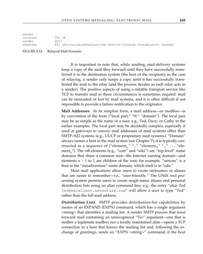
O P E N S Y S T E M S M E S S A G I N G : E L E C T R O N I C M A I L 169
sender .receiver 250 OKsender QUITreceiver 221 serious.misadventure.edu Service closing transmission channel
FIGURE 8.14 Relayed Mail Scenario
It is important to note that, while sending, mail-delivery systemskeep a copy of the mail they forward until they have successfully trans-ferred it to the destination system (the host of the recipient); in the caseof relaying, a sender only keeps a copy until it has successfully trans-ferred the mail to the relay (and the process iterates as each relay acts asa sender). The positive aspects of using a reliable transport service likeTCP to transfer mail in these circumstances is sometimes negated: mailcan be misrouted or lost by mail systems, and it is often difficult if notimpossible to provide a failure notification to the originator.
Mail Addresses—In its simplest form, a mail address—or mailbox—isby convention of the form {“local part,” “@,” “domain”}. The local partmay be as simple as the name of a user; e.g., Ted, Dave, or Cathy in theearlier examples. The local part may be decidedly complex, especially ifused at gateways to convey mail addresses of mail systems other thanSMTP/822 systems (e.g., UUCP or proprietary mail systems). “Domain”always names a host in the mail system (see Chapter 7); it is typically con-structed as a sequence of {“element1,” “.,” “element2,” “.,” . . . “ele-mentn”}. The nth elements (e.g., “com” and “edu”) are “top-level” namedomains that share a common root—the Internet naming domain—andelements n – 1 to 1 are children of the root; for example, “serious” is ahost in the “misadventure” name domain, which itself is in “edu.”
Most mail applications allow users to create nicknames or aliasesthat are easier to remember—i.e., “user-friendly.” The UNIX mail pro-cessing system permits users to create single-name aliases and personaldistribution lists using an alias command line; e.g., the entry “alias [email protected]” will allow a user to type “Ted”rather than the full mail address.
Distribution Lists—SMTP provides distribution-list capabilities bymeans of an EXPAND (EXPN) command, which has a single argument<string> that identifies a mailing list. A sender SMTP process that mustforward mail containing an unrecognized “To:” argument—one that isneither a legitimate mailbox nor a locally maintained alias—opens a TCPconnection to a host that knows the mailing list and, following the ex-change of greetings, sends an “EXPN <string>” command; if the host
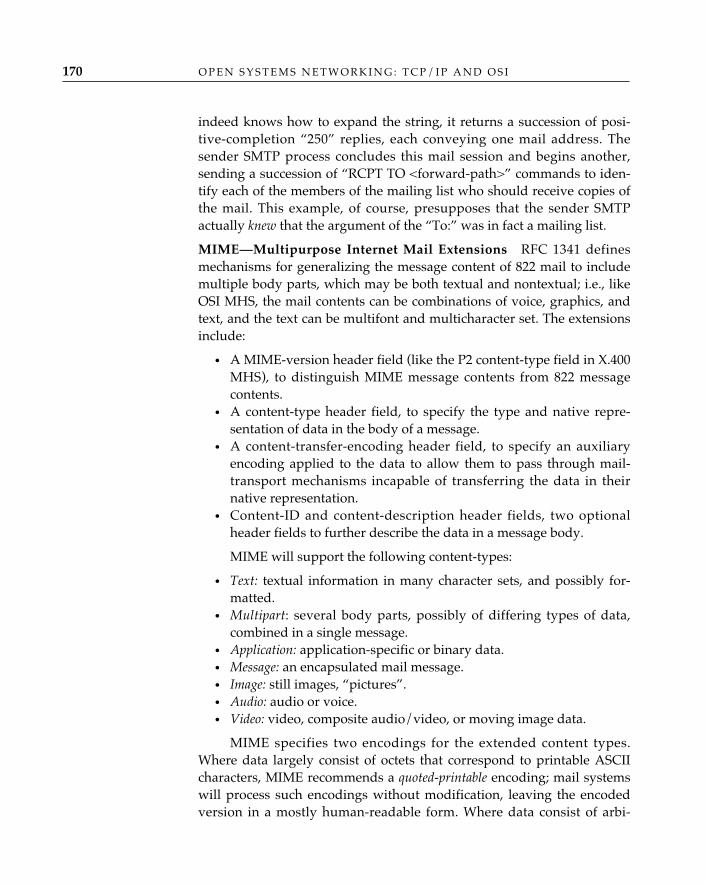
O P E N S Y S T E M S N E T W O R K I N G : T C P / I P A N D O S I170
indeed knows how to expand the string, it returns a succession of posi-tive-completion “250” replies, each conveying one mail address. Thesender SMTP process concludes this mail session and begins another,sending a succession of “RCPT TO <forward-path>” commands to iden-tify each of the members of the mailing list who should receive copies ofthe mail. This example, of course, presupposes that the sender SMTPactually knew that the argument of the “To:” was in fact a mailing list.
MIME—Multipurpose Internet Mail Extensions—RFC 1341 definesmechanisms for generalizing the message content of 822 mail to includemultiple body parts, which may be both textual and nontextual; i.e., likeOSI MHS, the mail contents can be combinations of voice, graphics, andtext, and the text can be multifont and multicharacter set. The extensionsinclude:
• A MIME-version header field (like the P2 content-type field in X.400MHS), to distinguish MIME message contents from 822 messagecontents.
• A content-type header field, to specify the type and native repre-sentation of data in the body of a message.
• A content-transfer-encoding header field, to specify an auxiliaryencoding applied to the data to allow them to pass through mail-transport mechanisms incapable of transferring the data in theirnative representation.
• Content-ID and content-description header fields, two optionalheader fields to further describe the data in a message body.
MIME will support the following content-types:
• Text: textual information in many character sets, and possibly for-matted.
• Multipart: several body parts, possibly of differing types of data,combined in a single message.
• Application: application-specific or binary data. • Message: an encapsulated mail message. • Image: still images, “pictures”.• Audio: audio or voice.• Video: video, composite audio/video, or moving image data.
MIME specifies two encodings for the extended content types.Where data largely consist of octets that correspond to printable ASCIIcharacters, MIME recommends a quoted-printable encoding; mail systemswill process such encodings without modification, leaving the encodedversion in a mostly human-readable form. Where data consist of arbi-
O P E N S Y S T E M S M E S S A G I N G : E L E C T R O N I C M A I L 171
trary octet strings, MIME recommends Base64, a variant of the encodingscheme from RFC 1113; briefly, and proceeding from left to right, 24 bitsare grouped together, represented as output strings of four encoded 6-bitcharacters, and then translated into a single alphabetic character fromthe base-64 ASCII set.
MIME also describes extensions that permit the use of charactersets other than ASCII in text tokens of 822 header fields such as “Subject”or “Comments,” within a comment delimited by “(” and “),” and in aword or phrase in a “From,” “To,” or “cc” header field. Both the headerand body contents extensions are intended to be compatible with exist-ing mail implementations. MIME uses the mail header fields defined inRFC 822, leaving the field names intact and in ASCII, but extends theencoding of the field body by introducing the notion of an encoded word,which, although transparent to mail systems that do not implementMIME, conveys semantics in addition to the header field—e.g., a charac-ter set and encoding. Specifically, an encoded word begins and endswith an ASCII “=, ”and three arguments—character set, encoding, andencoded text—are bounded by an ASCII “?” (there are thus always four“?”s) and terminated by a SPACE or new line. The character sets includeUS-ASCII and the ISO/IEC 8859 (1987) ISO 8859 family of character sets.Like the MIME message body parts, the encoding is either an ASCII “B,”for Base64, or “Q,” for “quoted-printable.” The encoded text is any print-able ASCII character string. (Using “Q,” however, there are some con-straints; i.e., you cannot embed a “?” or SPACE in the string, and othercharacters—“/,” “|,” “<,” “>,” and “@”—are illegal in header fields,where they are significant.) Thus, using encoded text in the field body ofthe “To:” header field in the following fashion
To: =?ISO8859-1?Q?Andr=E9_?= Pirard <[email protected]>
allows one to encode the name “André Pirard” without sacrificing theaccent mark over the e. The loss of transparency in field bodies is smallin comparison to the gain for mail users who benefit from the extensions.
MIME is a promising and valuable method of enhancing the inter-working between Internet mail and the OSI Message Handling System:with it, the multimedia aspects of MHS can be extended to environmentswhere Internet mail is preferred.
RFC 1113, Privacy Enhancement for Internet Electronic Mail: Part I—MessageEncipherment and Authentication Procedures, describes how to provide con-fidentiality, authentication, and message integrity as-surance using cryp-tographic techniques on messages exchanged between originator and
Security
recipient user agent processes in environments where RFC 822 mail mes-sages are used. Like many extensions to TCP/IP applications having alarge embedded base, privacy-enhanced mail (PEM) is designed so thatthe mail-transfer agents—SMTP processes or any message-transfer sys-tem that supports RFC 822 mail message formats—aren’t affected by thedeployment of the extensions. PEM provides data confidentiality (protec-tion against unauthorized disclosure of a message and certain mail head-er fields); sender authentication (corroboration that the originator of amail message is indeed who he or she claims to be); message integrity(proof that the message has not been tampered with); and if asymmetrickey management is used, nonrepudiation of message origin (proof of theintegrity and origin of the message). These privacy facilities are providedby encoding a set of header fields to carry the cryptographic controlinformation and an encrypted message and conveying these as the textportion of an RFC 822-formatted mail message (the encrypted message isencoded in printable form). (See also RFC 1422, Privacy Enhancement forInternet Electronic Mail: Part II—Certificate-based Key Management, RFC-1423, Privacy Enhancement for Internet Electronic Mail: Part III—Algorithms,Modes, and Identifiers, and RFC 1424, Privacy Enhancement for InternetElectronic Mail: Part IV—Key Certification and Related Services, whichsupercede RFCs 1113, 1114, and 1115.)
Interworking between MHS and Internet MailIn general, interworking between mail applications involves any or all ofthe following:
• Mail address translation—e.g., from OSI MHS O/R names to Inter-net mailbox addresses.
• Protocol mapping—e.g., from RFC 822 Internet text message formatto an X.400 interpersonal message (P2), or SMTP to X.400 messagetransfer access protocol (P1).
• Message content handling—the preservation of content type of allmessage content parts supported in one message transfer system toanother—e.g., the preservation of the text content of an RFC 822message across an X.400 MHS as content type 2.
Much of the useful work in interworking between OSI MHS andInternet mail systems has been performed in the IETF message-handlingworking groups and documented by Steve Hardcastle-Kille (RFC 987,RFC 1026, RFC 1137, RFC 1327), who has also done extensive work in the
O P E N S Y S T E M S N E T W O R K I N G : T C P / I P A N D O S I172
O P E N S Y S T E M S M E S S A G I N G : E L E C T R O N I C M A I L 173
development of mail interworking for the U.K. academic community,which uses the Joint Network Team or Grey Book mail system (Kille1984a, 1984b). The most recent proposed standard, RFC 1327, definesinterworking or mapping between X.400-1988 and RFC 822, with back-ward compatibility with earlier mappings to X.400-1984–based mail sys-tems.
A comparison between Figures 8.4 and 8.13 suggests that the“header information” used when composing electronic mail in these twosystems is quite similar. The mappings between the RFC 822 messageheader and the interpersonal message system protocol (P2) described inX.420-1988 when an 822 message system is the point of mail origin areaccomplished by mapping the RFC 822 header into an extension field inthe IPM. When an X.400 MHS is the point of mail origin, mappings areaccomplished by (1) mapping existing RFC 822 header fields onto corre-sponding IPMS protocol information and (2) introducing extensionheader fields where required. Currently, multipart bodies are supported,but with some loss of information; with MIME extensions, however, it isanticipated that further investigation into interworking between MIMEand the OSI MHS will yield mappings that will preserve multipart mes-sages, as well as messages containing multimedia body parts.
Mapping of an RFC 822 mail address is onto an X.400 O/R address.The simplest incarnation of this mapping assumes that the country,ADMD, PRMD, organization, and organizational unit attributes in anO/R address are present; these are mapped to elements in the domainpart of an 822 address. The personal name is mapped to the local or userpart. For example, it isn’t that difficult to see how the following e-mailaddresses can be converted into equivalent O/R addresses:
[email protected] [email protected] = “GB” C = “US”ADMD = “GOLD 400” ADMD = “ATTCOM”PRMD = “ac” PRMD = “va”O = “UCL” O = “reston”OU = “cs” OU = “nri”PN = “S.Kille” S = “mdavies”
Of course, when attributes corresponding to local and domain partsare absent or ambiguous—e.g., a mail address of the form“[email protected]” or “[email protected]”—things get stickier. RFC 1327 devotesconsiderable attention to the details of providing gateway mappings
O P E N S Y S T E M S N E T W O R K I N G : T C P / I P A N D O S I174
between complex RFC 822 addresses and O/R addresses and also describesmethods of mapping between directory names and RFC 822 addresses.
RFC 1327 is unlikely to be the last of the 822-to-MHS interworkingdocuments; the current incarnation of interworking does not yet addresssecurity extensions or dealing with different and multiple message con-tent types. These are likely to be more important as field experience withX.400-1988, MIME, and privacy-enhanced mail increases. In any event,don’t be surprised if you begin to receive via your Internet mailer mailheaders such as those shown in Figure 8.15.
From [email protected] Tues May 18 07:27:58 1993Return-Path: <[email protected]@sabre.bellcore.com>X400-Received: by mta mhs-relay.cs.wisc.edu in /PRMD=XNREN/ADMD= /C=US/;
Relayed; Tues, 18 May 1993 06:21:04 +0000X400-Received: by /PRMD=uninett/ADMD= /C=no/; Relayed;
Tues, 18 May 1993 06:18:10 +0000X400-Received: by /PRMD=uninett/ADMD= /C=no/; Relayed;
Tues, 18 May 1993 06:18:06 +0000Date: Tues, 18 May 1993 06:18:06 +0000X400-Originator: [email protected]: non-disclosure:;X400-Mts-Identifier: [/PRMD=uninett/ADMD= /C=no/;930518131806]X400-Content-Type: P2-1984 (2)Content-Identifier: 2483Conversion: ProhibitedFrom: Alf Hansen <[email protected]>To: Erik Huizer <[email protected]> (IPM Return Requested)Cc: dave <[email protected]> (IPM Return Requested),skh <[email protected]> (IPM Return Requested),“Kevin.E.Jordan” <[email protected]> (IPM Return Requested),
“S.Kille” <[email protected]> (IPM Return Requested),“Harald.T.Alvestrand” <[email protected]> (IPM Return Requested),sjt <[email protected]> (IPM Return Requested),Megan Davies <[email protected]> (IPM Return Requested)
In-Reply-To: <[email protected]>Subject: Re: Boston IETF schedulingStatus: RO
Erik,. . .
FIGURE 8.15 822 Headers from an 822–MHS Relay
ConclusionThis chapter has examined the electronic mail and message handling ser-vices of OSI and the Internet. The evolution of the OSI MHS functionalmodel and protocol architecture was traced from the 1984 version to that
O P E N S Y S T E M S M E S S A G I N G : E L E C T R O N I C M A I L 175
described in X.400-1988. (Readers should note that the inability on thepart of standards makers to arrive at a consensus on the OSI application-layer structure in 1984 introduced perturbations not only in the MHSarchitecture but in the entire OSI upper-layer architecture; these are dis-cussed in Chapters 10 and 11.) The 1988 version of the OSI MHS is a sub-stantial improvement over its 1984 ancestor, providing a useful, scalable,and secure framework for multimedia messaging.
SMTP/822, or “Internet mail,” has evolved from a humble text-onlyplatform to a message handling service that is seemingly feature for fea-ture the equal of OSI MHS by the introduction of privacy enhanced mailand MIME. When PEM was introduced, and MIME shortly thereafter,hard-line Internetters were quick to proclaim X.400 dead, while equallyhard-line OSI types dismissed these SMTP extensions as yet another hack.There is, in fact, more posturing than truth in such statements. Readersare asked to consider whether it is really important that there be a winneror whether the true benefit of having two equally powerful message-han-dling services is that interworking between them will result in a consider-ably more robust and globally interconnected electronic mail system.
9 NETWORK MANAGEMENT
Why all the interest in network management, and why all the effort? Partof the answer lies in the ever-increasing importance of networks andinternetworking. Today, the phrase mission critical applies not just to net-works that support space-exploration applications but also to those thatsupport sales, airline and hotel reservation systems, health care, com-modity and stock exchanges, commerce, and finance. Nearly every busi-ness depends on the health of its network to remain in operation. Likethe dial tone in the voice network, the availability of facilities for datacommunications is now taken for granted, and there is an increasedincentive to keep networks healthy.
Part of the answer lies in the actual number and size of networks.Data network operation is no longer a matter of managing one site, withone vendor’s equipment and one vendor’s proprietary managementtools. And increasingly, as enterprises connect their networks to shareinformation, “operations” crosses administrative boundaries as well.
These observations address the question “why all the interest?” Theanswer to the question “why all the effort?” lies in the fact that untilrecently, with only a handful of noteworthy exceptions, managementand diagnostic tools for data networks were either proprietary or home-brewed. There is thus both opportunity and incentive for those who wishto become involved in a new technology that can be put to practical usein a short time frame.
The OSI and Internet communities have each developed technolo-gies to solve the problem of network management. The Internet ap-proach is based on a management protocol called Simple Network Man-agement Protocol (SNMP), designed with the philosophy apparent from
177
its name: keep it simple. The OSI approach is based on a managementprotocol called Common Management Information Protocol (CMIP), alsodesigned with the philosophy apparent from its name: provide a com-mon protocol flexible enough to solve all problems.
This fundamental difference in design philosophies created the pre-dictable result. SNMP was designed and deployed quickly, solving theimmediate problem of managing the Internet and then moving beyond toother networking environments. CMIP took longer to design, and itsdeployment is slowed both by its inherent complexity and by the marketsuccess of SNMP. Nevertheless, both SNMP and CMIP technologies existtoday and will likely continue to be deployed in future network- and sys-tems-management products. And it is also true that these two manage-ment models do not address the entirety of the issues related to networkmanagement. It is therefore advisable to explore what each tool has tooffer and to construct complete management solutions that solve real-world user needs based on whatever combination of technologies isappropriate.
The Internet Approach: Keep It SimpleWhile the Internet remained a modest collection of hosts, gateways, andusers, network management was an “ad hack” practice, and home-brewmanagement, abetted by the sturdy ICMP “ping” facility, was the norm.As the Internet grew both in size and in importance to its users, and asTCP/IP-based internetworking expanded outside the research communi-ty, the need for network management capabilities grew. By 1988, re-search and experimentation by the Internet community led to the defini-tion of two management systems and associated management protocols:the High-Level Entity Management System (HEMS) (Partridge and Trewitt1988; RFC 1021; RFC 1022) and the Simple Network Management Protocol(RFC 1157).
Both of these management protocols were designed to operate overthe TCP/IP protocol suite. However, because of a strong desire on thepart of U.S. government agencies to have a graceful transition fromTCP/IP to OSI, the research community agreed to abandon the longer-term HEMS effort in favor of a management framework based on OSICMIP standards (the trials, travails, and tragedy of OSI Common Man-agement over TCP/IP are discussed later in this chapter).
SNMP was initially viewed as an interim step on the road to thelonger-term OSI solution; of course, nothing is ever truly interim. SNMP
O P E N S Y S T E M S N E T W O R K I N G : T C P / I P A N D O S I178
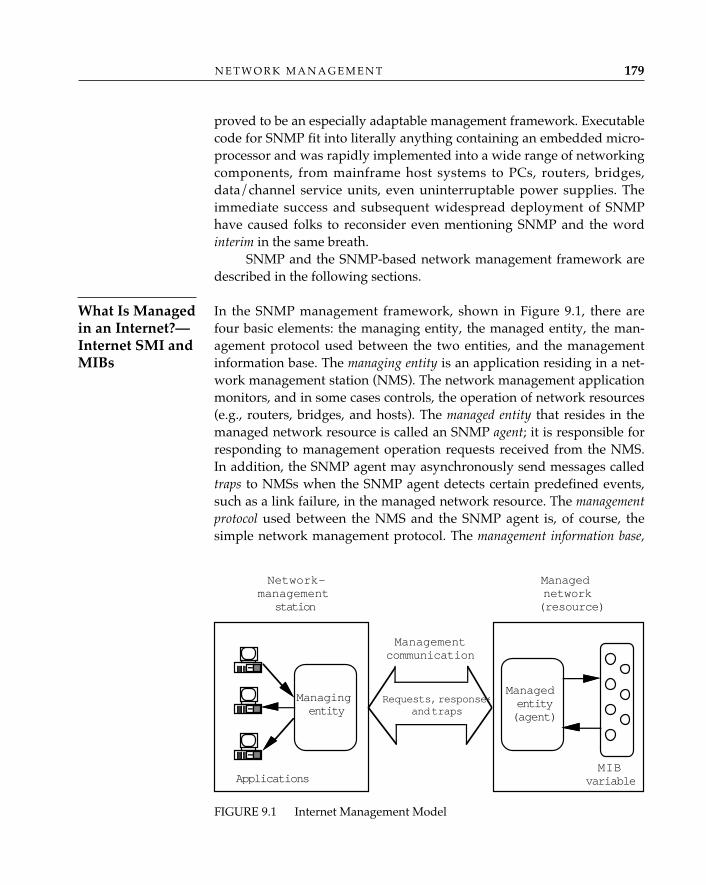
proved to be an especially adaptable management framework. Executablecode for SNMP fit into literally anything containing an embedded micro-processor and was rapidly implemented into a wide range of networkingcomponents, from mainframe host systems to PCs, routers, bridges,data/channel service units, even uninterruptable power supplies. Theimmediate success and subsequent widespread deployment of SNMPhave caused folks to reconsider even mentioning SNMP and the wordinterim in the same breath.
SNMP and the SNMP-based network management framework aredescribed in the following sections.
In the SNMP management framework, shown in Figure 9.1, there arefour basic elements: the managing entity, the managed entity, the man-agement protocol used between the two entities, and the managementinformation base. The managing entity is an application residing in a net-work management station (NMS). The network management applicationmonitors, and in some cases controls, the operation of network resources(e.g., routers, bridges, and hosts). The managed entity that resides in themanaged network resource is called an SNMP agent; it is responsible forresponding to management operation requests received from the NMS.In addition, the SNMP agent may asynchronously send messages calledtraps to NMSs when the SNMP agent detects certain predefined events,such as a link failure, in the managed network resource. The managementprotocol used between the NMS and the SNMP agent is, of course, thesimple network management protocol. The management information base,
N E T W O R K M A N A G E M E N T 179
What Is Managedin an Internet?—Internet SMI andMIBs
FIGURE 9.1 Internet Management Model
Managednetwork(resource)
Managementcommunication
Requests, responsesand traps
Managingentity
Managedentity(agent)
MIBvariableApplications
Network-management
station
O P E N S Y S T E M S N E T W O R K I N G : T C P / I P A N D O S I180
or MIB, is a logical store of information used to support network man-agement (RFC 1213).
SNMP-based network management is based on a philosophy ofkeeping the required management overhead and functionality at a mini-mum for both the network and the managed resources (this is referred toin The Simple Book as the Fundamental Axiom of Network Management[Rose 1991]). In the SNMP model, the network-management station isexpected to perform more network management–related processing thanthe managed resource since (1) the network management station’s primaryjob is to support network management, and (2) generally speaking, thenetwork management station and its users have a clearer understandingof the “big picture” of the network than any individual managed re-source. The NMS usually has applications that may show maps of themanaged network, chart various statistics (received/sent packets, errorpackets, etc.), and notify an operator of errors via audible or visiblealarms. The NMS may even perform some rules-based analysis—alsohyped as artificial intelligence or applied learning—to help the networkmanager maintain the network and resolve network problems.
The managed network resource’s primary function is not networkmanagement: routers should route, bridges should bridge, and hostsshould host applications. For these resources, network managementshould be secondary. In the SNMP model, the agent is expected to devoteless to network management processing than the NMS, and typically per-forms management operations in response to requests from the NMS.With SNMP, network management is based on the NMS polling theagents in a network for information; it is expected that generating re-sponses to polls should impose less processing at a managed resourcethan the often computationally complex process of diagnosing problems.
SNMP-based network management further refines the notion ofpolling by applying a network management paradigm known as trap-directed polling. In trap-directed polling, the NMS polls an SNMP agent inresponse to an asynchronously generated alarm called a trap message1 itreceives from the SNMP agent (as opposed to continually polling forinformation from the SNMP agent or expecting the SNMP agent todownload information on a regular basis). Trap-directed polling relievesthe SNMP agent from the burden of monitoring for thresholds or main-taining schedules for downloads, and relieves the network of the trafficcaused by frequent polling for information. Trap messages, however, are
1. The trap message indicates that a noteworthy event has occurred; e.g., a link hasfailed, a link has been restored, or a managed resource has re-booted.
not delivered reliably, so it is not advisable to eliminate polling in theSNMP management model and rely solely on event notifications for di-rection. A prudent management practice is to poll for information thatdescribes the operational status of all managed resources, in a “round-robin” fashion.
Polling is useful for some aspects of network management—espe-cially fault detection, isolation, and recovery—but there are other occa-sions when large amounts of network data must be collected for subse-quent review and analysis. Frequent requests for large amounts of net-work data impose a heavy load on managed resources, and are discour-aged. Polling can indeed be a two-edged sword; if it is applied incorrectly,by polling too frequently, network managers (especially those with newtools) can figuratively bring a network or managed resource to its knees.
One network manager the authors know tried polling networkresources for eight pieces of information on every interface
every 30 seconds. The managed network resources were spending more timeresponding to network management queries than to routing network traffic. Atthe end of a day of intensive polling, the network manager had a gigabyte of net-work information, a network with lousy performance, and very irritable users.With a little more experience, the network manager now polls for less informa-tion less frequently.
The initial Internet efforts focused on three aspects of network manage-ment: defining the minimum set of information that is useful and neces-sary for managing the Internet and its components; identifying how thatset of information would be defined; and finally, the management proto-col itself.
The management information base (MIB) is the logical store of in-formation used to support network management of the Internet. Thegoal in designing the MIB was to identify a minimal set of useful infor-mation that could be implemented quickly without unduly burdeningthe managed network resources. The first MIB (or MIB I) was describedin RFC 1066 in 1988. MIB I contained 114 objects, or types/pieces of infor-mation that were viewed as essential for managing TCP/IP-based net-works. After additional work and experimentation, some objects weredeleted and new objects were added to the MIB, which is now calledMIB II (RFC 1213).
MIB II contains over 170 objects organized into nine groups: system,
✧AHA✧
N E T W O R K M A N A G E M E N T 181
The ManagementInformation Base
O P E N S Y S T E M S N E T W O R K I N G : T C P / I P A N D O S I182
interfaces, ip, icmp, tcp, udp, egp, transmission, and snmp (RFC 1213). Thesystem group includes general information on the managed networkresource; examples include system name and location. The interfacesgroup contains information relevant to specific interfaces on a managedresource; examples include interface index, interface type, and interfacedescription. The ip, icmp, tcp, udp, egp, and snmp groups contain informa-tion relevant to the protocols, such as counts of protocol packets sent andreceived.
The transmission group is one of the extension mechanisms thatallow graceful addition of network management information to MIB II. Itis structured to allow for addition of MIB subsets (called modules) specificto transmission media. For example, MIB modules for access to the digi-tal transmission facilities of the telephony network (DS1- and DS3-basedaccess; see Chapter 15) are defined in separate RFCs but are consideredto exist as branches of the MIB II transmission group. Other examples ofmedia-specific transmission MIB modules include the token-ring andtoken-bus LANs, FDDI, the SMDS interface protocol, and frame-relaymodules (again, see Chapter 15). This modularity in the MIB structure isone mechanism for supporting the various, changing technologies thatunderlie the Internet, while leaving the fabric of network managementunchanged.
Even with all the information identified in MIB II and in the trans-mission MIBs, more information is available for information-hungry net-work managers. Managed objects that are applicable to a specific ven-dor’s products or protocols may be identified and posted electronicallyas enterprise-specific MIBs. “It’s raining MIBs” is a phrase frequentlyused to describe the tremendous growth in the number of MIBs availablefor SNMP-based network management.
Why are there so many MIBs and so many objects to manage?Engineers rather than network operators have traditionally
composed MIB modules. All too often enamored with their (well, our) technolo-gies, they (we) get carried away. As one participant in the IEEE 802.6 subcom-mittee once suggested, they (we) “count everything that moves, and even thingsthat don’t move, just to be sure that they stay in the same place.” Staff at theNSF Network Operations Center have often suggested that “any more than six[objects] is too many.” A downside of having so many objects to keep track of isthat the essence of SNMP management is ultimately compromised; despite goodintentions, managed resources are spending too much time counting things!
✧AHA✧
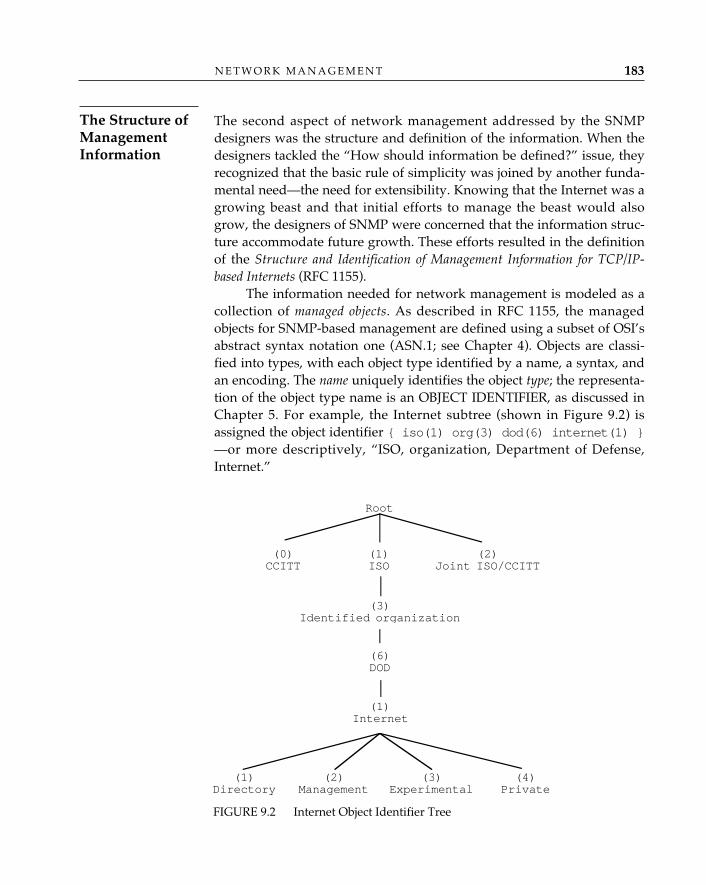
The second aspect of network management addressed by the SNMPdesigners was the structure and definition of the information. When thedesigners tackled the “How should information be defined?” issue, theyrecognized that the basic rule of simplicity was joined by another funda-mental need—the need for extensibility. Knowing that the Internet was agrowing beast and that initial efforts to manage the beast would alsogrow, the designers of SNMP were concerned that the information struc-ture accommodate future growth. These efforts resulted in the definitionof the Structure and Identification of Management Information for TCP/IP-based Internets (RFC 1155).
The information needed for network management is modeled as acollection of managed objects. As described in RFC 1155, the managedobjects for SNMP-based management are defined using a subset of OSI’sabstract syntax notation one (ASN.1; see Chapter 4). Objects are classi-fied into types, with each object type identified by a name, a syntax, andan encoding. The name uniquely identifies the object type; the representa-tion of the object type name is an OBJECT IDENTIFIER, as discussed inChapter 5. For example, the Internet subtree (shown in Figure 9.2) isassigned the object identifier { iso(1) org(3) dod(6) internet(1) }—or more descriptively, “ISO, organization, Department of Defense,Internet.”
N E T W O R K M A N A G E M E N T 183
The Structure ofManagementInformation
FIGURE 9.2 Internet Object Identifier Tree
Root
(0)CCITT
(1)ISO
(2)Joint ISO/CCITT
(3)Identified organization
(6)DOD
(1)Internet
(1)Directory
(2)Management
(3)Experimental
(4)Private
O P E N S Y S T E M S N E T W O R K I N G : T C P / I P A N D O S I184
Under the Internet subtree, there are four nodes: directory (1), man-agement (2), experimental (3), and private (4). The MIB II standardobjects for SNMP-based management are defined in the managementbranch. Proposed objects are classified under the experimental branch,and objects appropriate for specific products are defined in the privatebranch. By allocating the fourth branch to “private,” the SNMP designersprovided a mechanism for extending the naming structure to includeinformation that was pertinent to specific products but not required forgeneral use in the Internet or for network management. It is under theprivate node that companies attempt to distinguish their agents fromtheir competitors’ by identifying even more objects to manage!
The syntax is an ASN.1 data structure used to describe a particularobject type. Examples of syntax include INTEGER, OCTETSTRING, andNULL. The encoding identifies how instances or specific occurrences of anobject type are specified using the syntax.
It is the object instances, not object types, that are of interest duringnetwork management operations. When an interface is causing network-ing problems, a network manager needs to know specifically whichinterface is misbehaving, not just that an interface object type exists. Theinstance is identified by its object type name and an instance identifier,which is specified in the MIB containing that object. For example, in theinterfaces table—the ifTable group of MIB II (RFC 1213)—instances areidentified by ifIndex, which is a unique integer value assigned to eachinterface. The instance is depicted as the object identifier with the gener-alized format x.y, where x refers to the object type identifier and y is theinstance identifier (Rose 1991). Consider, for example, the objectifOperStatus of the interfaces table of MIB II. The ifOperStatusvalue indicates the status—up, down, or testing—of an interface. For thisexample, assume that the network manager has received a trap messageindicating a link-down condition on interface 7 and that the networkmanager wants to verify the operational status of the interface. The objectidentifier for ifOperStatus—or the “x” part of x.y—is { iso(1)org(3) dod(6) internet(1) mgmt(2) mib-2(1) inter-faces(2) ifTable(2) ifEntry(1) ifOperStatus(8) },numerically represented as “1.3.6.1.2.1.2.2.1.8.” The object identifier forthe specific instance, interface 7, is “1.3.6.1.2.1.2.2.1.8.7.” The NMS pollsthe router’s SNMP agent for the value of this instance using this objectidentifier; the SNMP agent responds with a value indicating that theinterface-7 operational status is down. (Note: The pairing of the name ofan object or a variable with the variable’s value is called a variable bind-ing, or VarBind.) Based on this knowledge, the network manager would
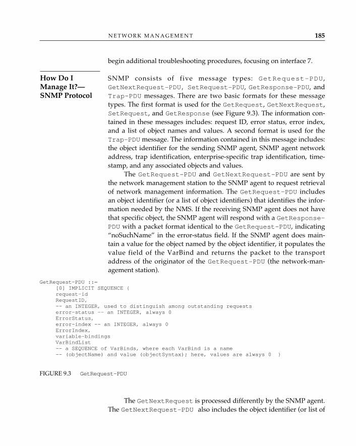
N E T W O R K M A N A G E M E N T 185
begin additional troubleshooting procedures, focusing on interface 7.
SNMP consists of five message types: GetRequest-PDU ,GetNextRequest-PDU, SetRequest-PDU, GetResponse-PDU, andTrap-PDU messages. There are two basic formats for these messagetypes. The first format is used for the GetRequest, GetNextRequest,SetRequest, and GetResponse (see Figure 9.3). The information con-tained in these messages includes: request ID, error status, error index,and a list of object names and values. A second format is used for theTrap-PDU message. The information contained in this message includes:the object identifier for the sending SNMP agent, SNMP agent networkaddress, trap identification, enterprise-specific trap identification, time-stamp, and any associated objects and values.
The GetRequest-PDU and GetNextRequest-PDU are sent bythe network management station to the SNMP agent to request retrievalof network management information. The GetRequest-PDU includesan object identifier (or a list of object identifiers) that identifies the infor-mation needed by the NMS. If the receiving SNMP agent does not havethat specific object, the SNMP agent will respond with a GetResponse-PDU with a packet format identical to the GetRequest-PDU, indicating“noSuchName” in the error-status field. If the SNMP agent does main-tain a value for the object named by the object identifier, it populates thevalue field of the VarBind and returns the packet to the transportaddress of the originator of the GetRequest-PDU (the network-man-agement station).
GetRequest-PDU ::=[0] IMPLICIT SEQUENCE {request-idRequestID,-- an INTEGER, used to distinguish among outstanding requestserror-status -- an INTEGER, always 0ErrorStatus,error-index -- an INTEGER, always 0ErrorIndex,variable-bindingsVarBindList-- a SEQUENCE of VarBinds, where each VarBind is a name -- (objectName) and value (objectSyntax); here, values are always 0 }
FIGURE 9.3 GetRequest-PDU
The GetNextRequest is processed differently by the SNMP agent.The GetNextRequest-PDU also includes the object identifier (or list of
How Do IManage It?—SNMP Protocol
O P E N S Y S T E M S N E T W O R K I N G : T C P / I P A N D O S I186
object identifiers) for the requested information; however, the SNMPagent will respond to a GetNextRequest-PDU with the next lexico-graphical instance in relation to the sent object identifier. The GetNextRequest-PDU is referred to as the “powerful GetNext operator” (in par-ticular, see Rose [1991]) because of this feature and the relative ease of itsimplementation.2
The SetRequest-PDU is used by the network management stationto request that the value of an object instance be changed by the SNMPagent. For example, the network management station may use a Set-Request-PDU to request an update to a routing table entry or to changethe desired status of an interface to “testing.” For sets, the SNMP agentdesigners and implementers must do additional work to identify the cor-rect combination of information needed from the NMS for the set and toensure that the set is performed correctly in the managed resource. Uponcompletion of the set operation, the SNMP agent returns aGetResponse-PDU with the value in the VarBind indicating the resultof the set operation.3
There are security concerns related to SNMP; for example, changesto values of configuration-related managed objects, introduced either bymalicious intrusion or by error, can disrupt the performance of a net-work, even bring it to a halt, and monitoring of network managementtraffic can reveal user behavior patterns and perhaps help an intruderidentify critical (frequently used) resources. (The security aspects of SNMPare discussed later in this chapter.) For these reasons, the set operation isconsidered the “least simple” of the SNMP management operations.
The Trap-PDU, unlike the GetRequest-PDU and GetNextRequest-PDU messages, is initiated by the SNMP agent. A small num-ber of predefined events, which are identified in MIB modules, are trig-gers for the SNMP agent to send the Trap-PDU message to authorizednetwork management stations. RFC 1157, “SNMP,” defines five trap mes-sages: cold start, warm start, link up, link down, and authentication fail-ure (i.e., attempts by an unrecognized NMS to get or set values of man-aged ob-jects); others have been identified in enterprise-specific MIBs.After the event is detected by the SNMP agent, it makes a “best-effort”
2. If the SNMP agent does not have a “next lexicographical instance” to return, then aGetResponse message indicating the “noSuchName” error will be returned.3. Note that since SNMP is datagram-based, the GetResponse-PDU may be lost; i.e.,the NMS may receive no confirmation of the completion of the set operation. To determinethe results of a set operation, implementations are likely to run a timer following anattempt at a set operation; if the time expires and no GetReponse-PDU has arrived, theNMS will issue a GetRequest-PDU to determine the value of the object upon which theset operation was performed.
N E T W O R K M A N A G E M E N T 187
attempt to notify the NMS. The underlying transport protocols (e.g.,UDP, TCP) determine whether the network will attempt resends, etc., totransport the message to the destination. (Note that the recommendedtransport for SNMP, User Datagram Protocol [UDP], is an unreliabledatagram protocol and that, typically, there are neither retransmissionsnor notifications of loss of a Trap message.)
Examples of Trap-Directed Polling—When an SNMP agent in a routerdetects that it can no longer send or receive traffic across a physical inter-face, it sends a link-down trap to the network management station. Afterreceiving the trap at the NMS, a network operator will initiate trouble-resolution steps—or follow a “recipe” of actions—to identify the sourceof the problem. First, the operator may use the NMS application to pollfor the interface’s operational status to verify that the status of the inter-face is indeed “down” (i.e., the NMS will send a GetRequest-PDUrequesting the value of the object ifOperStatus in MIB II and mayreceive a GetResponse-PDU with the value of ifOperStatus set to“down”). If the operator elects to diagnose the fault in a “bottom-up”fashion, she may poll for physical-layer information from the transmis-sion MIB for this particular interface type. For example, if this were a1.544-Mbps link based on the DS1 signal, the operator might request val-ues from the DS1 configuration table (RFC 1232), which contains informa-tion on the alarm and loopback states of an interface, and the DS1 currenttable, which contains counts of DS1-related errors (RFC 1232). If thesepolls yielded information that isolated the fault to the satisfaction of thenetwork operator, the NMS might proceed by calling in a trouble reportto the telephone company; if not, the NMS might continue polling forerrors until the reason for the error condition is found.
Note that although fault isolation can be trap-directed, it need notbe so; in fact, since there are no guarantees that Trap messages will bedelivered, NMS applications often rely on repeated polling of one ormore specific objects—e.g., the ifOperStatus—and monitor for achange in value. In practice, more than a handful of NMS applicationsstill rely on an echo packet or a ping facility to determine loss of reacha-bility to a managed resource; if the ifOperStatus changes, or the echorequests fail to elicit an echo reply after a given number of attempts, theNMS application informs the operator that the status of a managedresource has changed or cannot be determined, and the operator willthen proceed with the troubleshooting previously described.
The network-management applications in the NMS may automatesome of the protocol exchanges with the SNMP agent so that the net-
work operator does not have to manually initiate polling for trouble reso-lution. Also, some applications automatically monitor the status of themanaged network resources. For example, some SNMP-based applica-tions can display the managed network as a diagram of links and nodes.The links and nodes are shown in different colors to indicate their status;some applications show links that have gone “down” in red and linksthat are “up” in green. These applications generally poll the SNMPagents for the ifOperStatus values of the relevant interfaces on a regu-lar basis (or alternatively, use ping). The ifOperStatus values are thenused as the variable to determine the color changes for the maps. Thisallows for proactive monitoring of the network while minimizing thetraffic exchange required across the network. Other applications allowthe network manager to select statistics to be displayed in a graph. Theoutput graphically depicts trends in error and usage counts, allowing thenetwork manager to develop a clearer notion of trends.
SNMP is an application-level protocol. To avoid forced retransmissionsand to minimize the use of network bandwidth, SNMP was originallyspecified to run over the user datagram protocol, a connectionless trans-port protocol in the TCP/IP suite (see Chapter 12). Use of SNMP hasexpanded outside of TCP/IP-based networks. Standards for its use overother transport protocols such as AppleTalk, IPX, and OSI’s connection-less transport protocol—the so-called SNMP “over foo”4 effort—havebeen developed and are discussed later in this chapter.
The current, “community-string–based” SNMP offers what is known as atrivial authentication service. A community string is an OCTETSTRINGthat provides an authentication service similar to passwords. If thereceiving SNMP entity “knows” the community string received in anSNMP message, the message is considered authentic. Implementationsare also encouraged to check that the IP address received in the SNMPmessage is the correct IP address for that community string.
There are four main security concerns with community-string–based SNMP: message modification, unauthorized monitoring of mes-sages, masquerades, and replay. Each of these concerns is related to theresults of unauthorized access and possible changes to network-manage-ment information that may harm the functions of the network or a man-aged network resource.
To address these concerns, the Internet community has specified an
O P E N S Y S T E M S N E T W O R K I N G : T C P / I P A N D O S I188
SNMP and theProtocol Stack
Security andSNMP
4. Literally, “SNMP over anything.”
N E T W O R K M A N A G E M E N T 189
enhancement to the SNMP protocol that provides for additional securityfeatures (RFC 1351; RFC 1352; RFC 1353). The secure SNMP described inthis enhancement provides four security services: data-origin authentica-tion, data-integrity verification, privacy, and protection from replay.
One of the challenges in defining the secure SNMP protocols was toleave the basic SNMP messages unchanged. The designers accomplishedthis by identifying procedures that left the basic packets intact andadded “wrappers” containing the enhanced security-related informationto the message formats. Obviously, even with the basic packet headersleft unchanged, there are some changes to SNMP to accommodate thesecurity features. These changes involve the use of SNMP parties, a data-authentication algorithm, a data-privacy algorithm, and loosely synchro-nized clocks. Instead of using community strings, secure SNMP usesSNMP parties. An SNMP party represents a role that an SNMP entitytakes when performing SNMP management operations. Associated witheach SNMP party is a set of information specific to that party; this infor-mation includes SNMP party identifier, transport address, acceptablemessage size, and secret keys for the protocols. The secure SNMP proto-col provides for use of both an authentication protocol and a privacyprotocol for protecting SNMP messages. Currently, the message digest 5(MD5) algorithm (RFC 1321) is suggested for the authentication protocol,and the U.S. national data-encryption standard (DES) is suggested foruse as the privacy protocol. However, the structure of the protocols ismodular, and alternate authentication and privacy protocols may beused. The secure SNMP documents outline a system using private keyswith placeholders established for future public-key system use. Thesecure SNMP documents also outline a mechanism for key managementusing SNMP.
OSI Common Management: Flexibility, At A PriceISO began developing a network management extension to the OSI refer-ence model in the early 1980s, but did not complete this initial design phaseuntil almost a decade later. Many factors contributed to this delay, but per-haps the single biggest factor was that—unlike the authors of SNMP, whohad a mutual, clearly defined objective (“manage the Internet”)—the many,varied ISO members who developed CMIP had no single, common objec-tive. As is the case with so many ISO standards, the OSI NetworkManagement Framework (ISO/IEC 7498-4: 1989) describes a model that isincredibly general and can essentially mean almost anything to anyone.
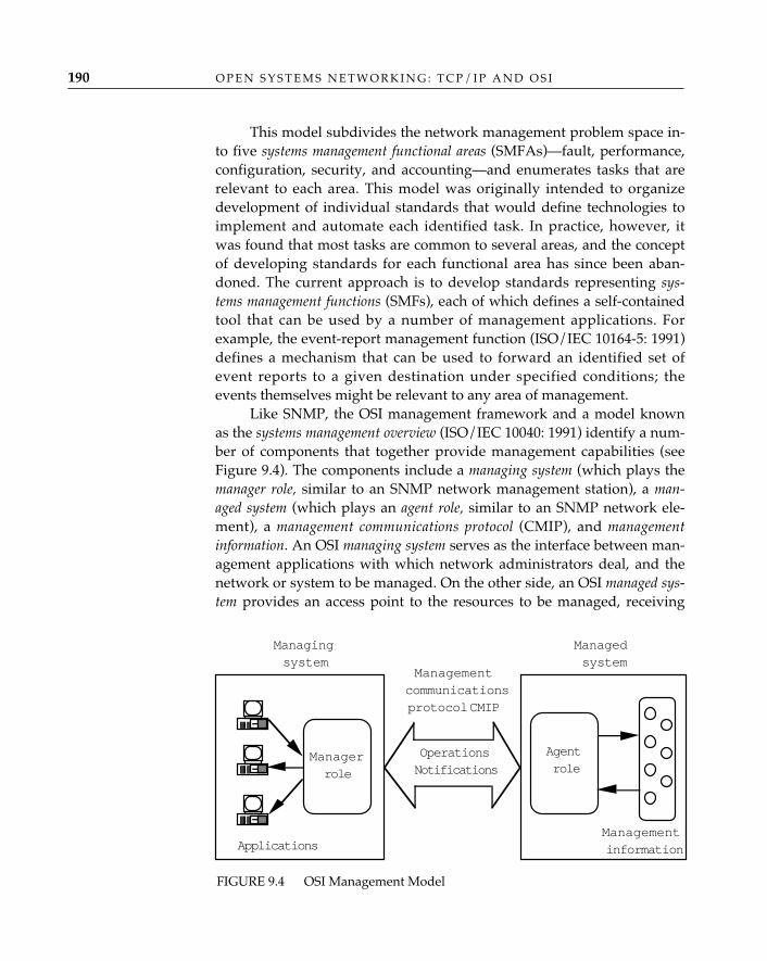
O P E N S Y S T E M S N E T W O R K I N G : T C P / I P A N D O S I190
This model subdivides the network management problem space in-to five systems management functional areas (SMFAs)—fault, performance,configuration, security, and accounting—and enumerates tasks that arerelevant to each area. This model was originally intended to organizedevelopment of individual standards that would define technologies toimplement and automate each identified task. In practice, however, itwas found that most tasks are common to several areas, and the conceptof developing standards for each functional area has since been aban-doned. The current approach is to develop standards representing sys-tems management functions (SMFs), each of which defines a self-containedtool that can be used by a number of management applications. Forexample, the event-report management function (ISO/IEC 10164-5: 1991)defines a mechanism that can be used to forward an identified set ofevent reports to a given destination under specified conditions; theevents themselves might be relevant to any area of management.
Like SNMP, the OSI management framework and a model knownas the systems management overview (ISO/IEC 10040: 1991) identify a num-ber of components that together provide management capabilities (seeFigure 9.4). The components include a managing system (which plays themanager role, similar to an SNMP network management station), a man-aged system (which plays an agent role, similar to an SNMP network ele-ment), a management communications protocol (CMIP), and managementinformation. An OSI managing system serves as the interface between man-agement applications with which network administrators deal, and thenetwork or system to be managed. On the other side, an OSI managed sys-tem provides an access point to the resources to be managed, receiving
FIGURE 9.4 OSI Management Model
Managedsystem
Managementcommunicationsprotocol CMIP
OperationsNotifications
Managerrole
Agentrole
ManagementinformationApplications
Managingsystem
and carrying out management operations directed at specific resourcesand forwarding notifications that indicate events pertaining to those re-sources. The resources themselves are modeled as managed objects; thecollection of all managed objects (conceptual) is known as the manage-ment information base (MIB).
Although these OSI concepts are similar to those describedpreviously for SNMP, the details and usage can be quite differ-
ent, as the authors show in this chapter. In fact, most of the difference—andhence, the debate between “simple” and “common” management—lies neither inthe concepts nor in the protocol bits; rather, it lies in the management paradigm.
Like the designers of SNMP, the architects of OSI management also rec-ognized that the resources to be managed were many and varied andthat a common representation would be necessary to manage them in amultivendor environment. The challenge was again to find a method of ab-stractly representing resources in a manner that would allow for com-mon understanding but also facilitate vendor extension and future en-hancement. The resulting approach, defined in the management informa-tion model (ISO/IEC 10165-1: 1991) and based on object-oriented technol-ogy and techniques, is extremely flexible; flexibility, however, does notcome without cost.
Using the management information model, resources such as sys-tems, protocol layer entities, and devices are modeled as managed objectclasses. Each managed object class has a number of properties that aremade visible over the management interface. Properties include:
• Attributes: detailed information that is known (or that might be con-figured) about the resource
• Notifications: significant events that might occur during the lifetimeof the resource
• Operations: management requests that can be performed on theresource
• Behavior: rules that describe the way the resource can be managed
These properties are encapsulated in a single, self-contained defini-tion that is assigned an object class identifier. This identifier—which maybe an OBJECT IDENTIFIER, as described in Chapter 5, or a simple inte-ger—serves as the target or source of all CMIP data units. Each property—attribute, notification, or operation—is also assigned a unique identifierto be included in CMIP data units.
✧AHA✧
N E T W O R K M A N A G E M E N T 191
What Do IManage?—OSIManagementInformationModel andGDMO
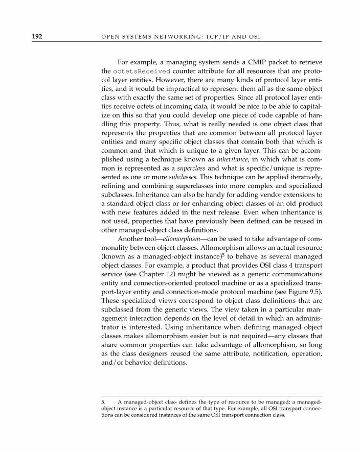
O P E N S Y S T E M S N E T W O R K I N G : T C P / I P A N D O S I192
For example, a managing system sends a CMIP packet to retrievethe octetsReceived counter attribute for all resources that are proto-col layer entities. However, there are many kinds of protocol layer enti-ties, and it would be impractical to represent them all as the same objectclass with exactly the same set of properties. Since all protocol layer enti-ties receive octets of incoming data, it would be nice to be able to capital-ize on this so that you could develop one piece of code capable of han-dling this property. Thus, what is really needed is one object class thatrepresents the properties that are common between all protocol layerentities and many specific object classes that contain both that which iscommon and that which is unique to a given layer. This can be accom-plished using a technique known as inheritance, in which what is com-mon is represented as a superclass and what is specific/unique is repre-sented as one or more subclasses. This technique can be applied iteratively,refining and combining superclasses into more complex and specializedsubclasses. Inheritance can also be handy for adding vendor extensions toa standard object class or for enhancing object classes of an old productwith new features added in the next release. Even when inheritance isnot used, properties that have previously been defined can be reused inother managed-object class definitions.
Another tool—allomorphism—can be used to take advantage of com-monality between object classes. Allomorphism allows an actual resource(known as a managed-object instance)5 to behave as several managedobject classes. For example, a product that provides OSI class 4 transportservice (see Chapter 12) might be viewed as a generic communicationsentity and connection-oriented protocol machine or as a specialized trans-port-layer entity and connection-mode protocol machine (see Figure 9.5).These specialized views correspond to object class definitions that aresubclassed from the generic views. The view taken in a particular man-agement interaction depends on the level of detail in which an adminis-trator is interested. Using inheritance when defining managed objectclasses makes allomorphism easier but is not required—any classes thatshare common properties can take advantage of allomorphism, so longas the class designers reused the same attribute, notification, operation,and/or behavior definitions.
5. A managed-object class defines the type of resource to be managed; a managed-object instance is a particular resource of that type. For example, all OSI transport connec-tions can be considered instances of the same OSI transport connection class.
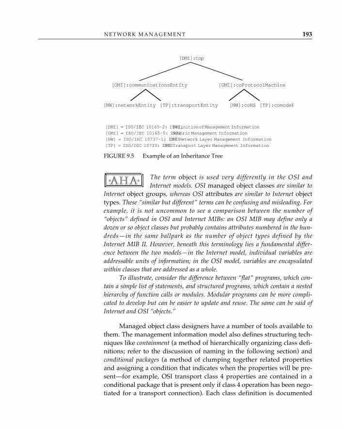
N E T W O R K M A N A G E M E N T 193
The term object is used very differently in the OSI andInternet models. OSI managed object classes are similar to
Internet object groups, whereas OSI attributes are similar to Internet objecttypes. These “similar but different” terms can be confusing and misleading. Forexample, it is not uncommon to see a comparison between the number of“objects” defined in OSI and Internet MIBs: an OSI MIB may define only adozen or so object classes but probably contains attributes numbered in the hun-dreds—in the same ballpark as the number of object types defined by theInternet MIB II. However, beneath this terminology lies a fundamental differ-ence between the two models—in the Internet model, individual variables areaddressable units of information; in the OSI model, variables are encapsulatedwithin classes that are addressed as a whole.
To illustrate, consider the difference between “flat” programs, which con-tain a simple list of statements, and structured programs, which contain a nestedhierarchy of function calls or modules. Modular programs can be more compli-cated to develop but can be easier to update and reuse. The same can be said ofInternet and OSI “objects.”
Managed object class designers have a number of tools available tothem. The management information model also defines structuring tech-niques like containment (a method of hierarchically organizing class defi-nitions; refer to the discussion of naming in the following section) andconditional packages (a method of clumping together related propertiesand assigning a condition that indicates when the properties will be pre-sent—for example, OSI transport class 4 properties are contained in aconditional package that is present only if class 4 operation has been nego-tiated for a transport connection). Each class definition is documented
✧AHA✧
[DMI]:top���
[GMI]:communicationsEntity [GMI]:coProtocolMachine��
[NW]:networkEntity [TP]:transportEntity [NW]:coNS [TP]:comodeP
[DMI] = ISO/IEC 10165-2: 1991,Definition of Management Information�
[GMI] = ISO/IEC 10165-5: 1992Generic Management Information�
[NW] = ISO/IEC 10737-1: 1993OSI Network Layer Management Information�
[TP] = ISO/IEC 10733: 1993OSI Transport Layer Management Information
FIGURE 9.5 Example of an Inheritance Tree
O P E N S Y S T E M S N E T W O R K I N G : T C P / I P A N D O S I194
using a format called Guidelines for the Definition of Managed Objects, orGDMO (ISO/IEC 10165-4: 1991).
GDMO contains a number of templates—blank forms that are filled into represent specific managed object classes and their properties. TheOBJECT CLASS template lists the packages that make up the class. ThePACKAGE template lists the properties included in the package. Eachproperty is defined using an ATTRIBUTE, ATTRIBUTE GROUP, NOTIFI-CATION, ACTION, PARAMETER, or BEHAVIOR template. Containmentrelationships between classes are represented using a NAME BINDINGtemplate. The filled-in GDMO templates define how the object class and itsproperties are represented in CMIP data units. For example, the ATTRI-BUTE template that defines octetsReceived refers to an ASN.1 typecalled “Count,” which is defined as an ASN.1 INTEGER (ISO/IEC 10165-2:1991). A CMIP request packet that retrieves the octetsReceivedattribute (identified by its OBJECT IDENTIFIER) causes the agent to returna CMIP response packet containing the octetsReceived attribute, theOID, and an INTEGER value. Unlike the Internet structure of managementinformation, the OSI guidelines allow any ASN.1 type to be used whendefining managed object class properties.
The object-oriented philosophy of subclassing/allomorphism andreuse described in the OSI management information model has beenused to define many resource-specific MIBs in GDMO format. Unlike theInternet community, which initially developed MIB I to manage theresources of the Internet, ISO has not focused its MIB6 developmentefforts on managing OSI stack resources. Initial MIBs, such as the OSINetwork Management Forum Library, published in 1990, were de-veloped based on preliminary versions of the Guidelines for the Definitionof Managed Objects. The Definition of Management Information (DMI;ISO/IEC 10165-2: 1991) and Generic Managed Information (GMI; ISO/IECCD 10165-5: 1992), published in 1992, were the first MIBs based on thefinal (IS) version of the GDMO; these might be considered the ISO equiv-alent of Internet MIB II (RFC 1213) because they provide the foundationon which all other resource-specific MIBs are built. For example, theDefinition of Management Information defines an object class called “Top,”which is the ultimate superclass—it contains attributes that are inheritedby all other managed object classes. The “definitions” and generic man-
6. In this chapter and throughout the industry, the term MIB is often used to refer to acollection of definitions. ISO standards have no single term for this concept, although man-agement information library is often used. ISO/IEC 7498-4: 1989 defines the term MIB as aconceptual collection of management information.
aged information model also define object classes such as “System” and“Network,” which are positioned at the top of the managed object treevisible to each agent. Now that the underlying management informationmodel and GDMO standards have been published, dozens of resource-specific MIBs are expected to appear by the end of 1993. The first ofthese—the OSI transport- and network-layer MIBs (ISO/IEC 10737-1:1992 and ISO/IEC 10733: 1992)—have already been completed.
As might be expected with a general model and format, the man-agement information model and GDMO are being used by a wide vari-ety of organizations throughout the industry, including standards bodies(ISO, CCITT, ANSI, IEEE, even the IETF), consortia (OSF, UI, X/Open),implementers’ workshops (OIW), procurement specifiers (NIST, U.S. AirForce), and vendors (telecom, datacom, systems). In the absence of a sin-gle governing body like the IETF, it is more difficult to keep track ofMIBs under development, where they are published, how they are regis-tered, etc. To address this problem, management information catalogs arebeing developed to provide both paper and on-line listings for publish-ing organizations, MIBs, and object classes. Also, since any registrationauthority can provide object identifiers for GDMO-based MIBs, mostorganizations act as their own registration authority; other MIB definersuse a public registration service, such as that provided by the OSI/NMForum.
ISO GDMO-based MIB development got off to a slow start,but all signs indicate that an “MIB explosion” will occur in
the 1993–94 time frame as the industry enters the “publish or perish” phase.Because MIBs to some extent dictate the choice of management protocol, avail-ability of Internet MIBs for many technologies may already have locked OSImanagement out of some potential markets (most notably, management of devicescritical for internetworking, such as routers and bridges). Thus, the eventualmarket success of OSI management rides largely on the ability of MIB definers topublish a comprehensive set of implementable GDMO-based MIBs—quickly!
Given an MIB that defines what you want to manage, the next obviousquestion is “How do I manage it?” In the traditional ISO style, the au-thors of the Common Management Information Service (ISO/IEC 9595: 1990)answered this question by defining a set of abstract service primitivesand parameters. CMIS can be thought of as a collection of function callsor methods that can be invoked to perform operations on or receive noti-fications from managed-object classes. The CMIS services are: M-GET,
✧AHA✧
N E T W O R K M A N A G E M E N T 195
How Do IManage It?—CMIP/CMIS andSMFs
M-SET, M-EVENT-REPORT, M-CREATE, M-DELETE, M-ACTION, andM-CANCEL-GET.
• The CMIS M-GET service can be used to retrieve the attributes ofnetwork and system resources—for example, to get the octets-Received counter attribute. This is similar to the “service” that isprovided when the SNMP Getrequest-PDU, GetResponse-PDU,and GetNextRequest-PDU messages are used.
• The CMIS M-SET service can be used to modify attributes—forexample, to configure OSI transport layer timer values. This is simi-lar to the service provided via the SNMP SetRequest-PDU (andcorresponding) GetRequest-PDU, GetResponse-PDU.
• The CMIS M-EVENT-REPORT can be used to signal a noteworthyoccurrence—for example, an excessive number of retransmissionsoccurring in the OSI transport layer. This is similar to the SNMPtrap message.
• The CMIS M-CREATE and M-DELETE services allow the manager torequest that managed-object instances be added or removed—forexample, an event-forwarding discriminator might be created to con-trol the flow of events from the agent to the manager (more on thissubject later in the chapter). There are no comparable SNMP mes-sages, although MIB designers may define tables in which rows canbe added or deleted using the SNMP SetRequest-PDU message.
• The CMIS M-ACTION service allows a manager to request that anyarbitrary operation be performed on or by a resource—for example,an ACTION might be used to activate or deactivate protocol layerentities. There are no comparable SNMP messages, although, again,MIB designers might provide a variable that, when set, would initi-ate an operation.
• The CMIS M-CANCEL-GET service allows a previously requestedM-GET to be aborted; the reason for this will become obvious laterin the chapter, when multiple replies are discussed. There is nocomparable SNMP message.
Each service primitive is converted into protocol data units by thecommon management information protocol specification (ISO/IEC 9596-1:1990);7 Figure 9.6 illustrates the CMIP GET packet, which is used to con-vey the semantics of the M-GET service.
O P E N S Y S T E M S N E T W O R K I N G : T C P / I P A N D O S I196
7. CMIS and CMIP version 1 were published in 1989, vendor experimentation began, afew show demos were held, and defects discovered during this process were reflected in
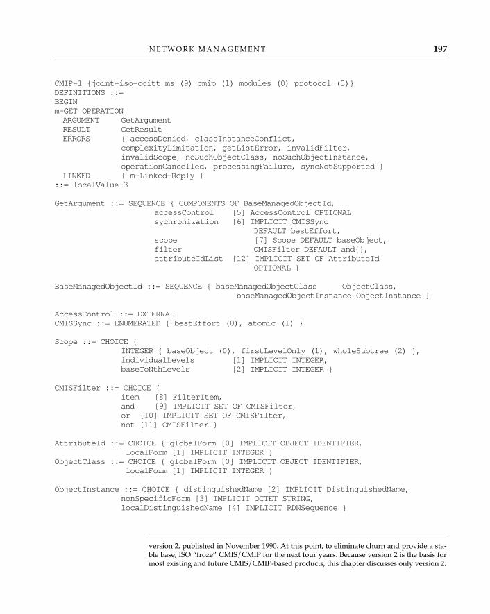
N E T W O R K M A N A G E M E N T 197
CMIP-1 {joint-iso-ccitt ms (9) cmip (1) modules (0) protocol (3)}DEFINITIONS ::=BEGINm-GET OPERATIONARGUMENT GetArgumentRESULT GetResultERRORS { accessDenied, classInstanceConflict,
complexityLimitation, getListError, invalidFilter,invalidScope, noSuchObjectClass, noSuchObjectInstance,operationCancelled, processingFailure, syncNotSupported }
LINKED { m-Linked-Reply }::= localValue 3
GetArgument ::= SEQUENCE { COMPONENTS OF BaseManagedObjectId,accessControl [5] AccessControl OPTIONAL,sychronization [6] IMPLICIT CMISSync
DEFAULT bestEffort,scope [7] Scope DEFAULT baseObject,filter CMISFilter DEFAULT and{},attributeIdList [12] IMPLICIT SET OF AttributeId
OPTIONAL }
BaseManagedObjectId ::= SEQUENCE { baseManagedObjectClass ObjectClass,baseManagedObjectInstance ObjectInstance }
AccessControl ::= EXTERNALCMISSync ::= ENUMERATED { bestEffort (0), atomic (1) }
Scope ::= CHOICE { INTEGER { baseObject (0), firstLevelOnly (1), wholeSubtree (2) },individualLevels [1] IMPLICIT INTEGER,baseToNthLevels [2] IMPLICIT INTEGER }
CMISFilter ::= CHOICE {item [8] FilterItem,and [9] IMPLICIT SET OF CMISFilter,or [10] IMPLICIT SET OF CMISFilter,not [11] CMISFilter }
AttributeId ::= CHOICE { globalForm [0] IMPLICIT OBJECT IDENTIFIER,localForm [1] IMPLICIT INTEGER }
ObjectClass ::= CHOICE { globalForm [0] IMPLICIT OBJECT IDENTIFIER,localForm [1] IMPLICIT INTEGER }
ObjectInstance ::= CHOICE { distinguishedName [2] IMPLICIT DistinguishedName,nonSpecificForm [3] IMPLICIT OCTET STRING,localDistinguishedName [4] IMPLICIT RDNSequence }
version 2, published in November 1990. At this point, to eliminate churn and provide a sta-ble base, ISO “froze” CMIS/CMIP for the next four years. Because version 2 is the basis formost existing and future CMIS/CMIP-based products, this chapter discusses only version 2.
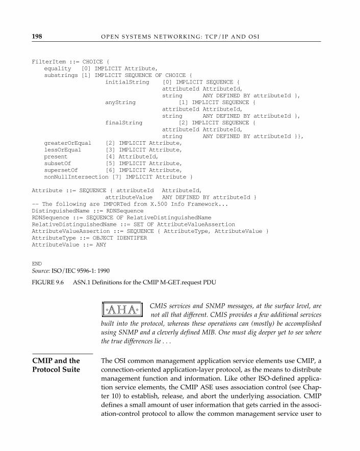
FilterItem ::= CHOICE {equality [0] IMPLICIT Attribute,substrings [1] IMPLICIT SEQUENCE OF CHOICE {
initialString [0] IMPLICIT SEQUENCE {attributeId AttributeId,string ANY DEFINED BY attributeId },
anyString [1] IMPLICIT SEQUENCE {attributeId AttributeId,string ANY DEFINED BY attributeId },
finalString [2] IMPLICIT SEQUENCE {attributeId AttributeId,string ANY DEFINED BY attributeId }},
greaterOrEqual [2] IMPLICIT Attribute,lessOrEqual [3] IMPLICIT Attribute,present [4] AttributeId,subsetOf [5] IMPLICIT Attribute,supersetOf [6] IMPLICIT Attribute,nonNullIntersection [7] IMPLICIT Attribute }
Attribute ::= SEQUENCE { attributeId AttributeId,attributeValue ANY DEFINED BY attributeId }
-- The following are IMPORTed from X.500 Info Framework...DistinguishedName ::= RDNSequence RDNSequence ::= SEQUENCE OF RelativeDistinguishedName RelativeDistinguishedName ::= SET OF AttributeValueAssertion AttributeValueAssertion ::= SEQUENCE { AttributeType, AttributeValue }AttributeType ::= OBJECT IDENTIFERAttributeValue ::= ANY
ENDSource: ISO/IEC 9596-1: 1990
FIGURE 9.6 ASN.1 Definitions for the CMIP M-GET.request PDU
CMIS services and SNMP messages, at the surface level, arenot all that different. CMIS provides a few additional services
built into the protocol, whereas these operations can (mostly) be accomplishedusing SNMP and a cleverly defined MIB. One must dig deeper yet to see wherethe true differences lie . . .
The OSI common management application service elements use CMIP, aconnection-oriented application-layer protocol, as the means to distributemanagement function and information. Like other ISO-defined applica-tion service elements, the CMIP ASE uses association control (see Chap-ter 10) to establish, release, and abort the underlying association. CMIPdefines a small amount of user information that gets carried in the associ-ation-control protocol to allow the common management service user to
✧AHA✧
O P E N S Y S T E M S N E T W O R K I N G : T C P / I P A N D O S I198
CMIP and theProtocol Suite
negotiate what the association is to be used for, but otherwise relies onthe normal association-control routine to set up management dialogues.The Systems Management Overview (ISO/IEC 10040: 1991) defines a singleapplication context that is used between management application serviceelements (see Chapter 10). When used over a full OSI stack, CMIPassumes reliable data transfer, allowing managers and agents to goabout their business without worrying about detecting loss or retrans-mission. Insulation from the transmission characteristics of the underly-ing network has many benefits—management applications and agentsdon’t need to be fine-tuned to “behave nicely” in each installation, andalternative transport mechanisms can be used with minimum disruption(for example, vendors deploy CMIP over proprietary transports as wellas OSI). However, as noted in the discussion of SNMP and UDP, connec-tion-oriented transport implies unsolicited retransmission, which can becostly—perhaps even fatal in times of network crisis, and more overheadfor brief management exchanges or interrogations (i.e., one must estab-lish a connection, exchange requests and responses, and tear down aconnection, as opposed to “simply” using datagrams).
OSI common management uses the invoke/result paradigm of remoteoperations; the CMIP protocol relies on an application service elementcalled remote operations (see Chapter 10). Every CMIS request maps to aremote operations service. The CMIP data units also map into remoteoperations protocol data units. These can be thought of as “envelopes”into which CMIP data units are inserted for transmission. CMIS alsomakes use of the linked-reply facility defined by remote operations tocover the case in which multiple replies are generated in response to asingle invoke (see Chapter 10). Because CMIP is built on top of remoteoperations, CMIS can be used in synchronous or asynchronous modes,as described in Chapter 10.
All CMIS operations are directed to a particular resource by includ-ing in the request a managed object class ID and a managed-objectinstance name. The managed object class can be an OBJECT IDENTIFIER(global form) or a simple integer (local form), although the “local form”can only be used when the manager and agent have a common under-standing—for example, to reduce overhead when using CMIP to managea private or proprietary network. The managed object instance name canbe either an X.500-style distinguished name, a local distinguished name(LDN), or a simple OCTETSTRING (limited to use in a well-defined con-text). Recall from Chapter 7 that distinguished names (DNs) are com-posed of a sequence of relative distinguished names (RDNs); each RDN
N E T W O R K M A N A G E M E N T 199
CMIP andRemoteOperations

O P E N S Y S T E M S N E T W O R K I N G : T C P / I P A N D O S I200
consists of an attribute value assertion (AVA) containing an attribute IDand value. This syntax allows unambiguous names to be constructed inany multivendor environment by using something called a containmenttree, an example of which is shown in Figure 9.7.
The containment tree organizes managed-object classes into a hier-archy, with the containing class being called the “superior” and the con-tained class being called the “subordinate.” Each instance in the tree hasits own name, unique within the context of its superior—this is the RDN.By concatenating all RDNs in a branch of the tree, you can derive a glob-ally unique distinguished name that identifies one and only one man-aged object instance. A local distinguished name is the name derivedfrom concatenating all RDNs in a branch of the subtree contained by the“System” managed object class.
Internet naming is based on statically defined object identi-fiers, whereas OSI naming is based on dynamically generated
distinguished names. Internet naming is always local to the agent, whereas OSInaming may be local to the system (LDN) or global (DN). As might be expected,OSI naming is more general and flexible than Internet naming, but at a cost—DNs and LDNs are typically longer than OIDs and, hence, more expensive toconstruct, process, and transmit.
✧AHA✧
Root�
[DMI]:System��
[TP]:TransportSubsystem��
[TP]:comodePM [TP]:tSAP��
[TP]:transportConnection .
Note: Names for an instance of the transportConnection managed object class: RDN = { Id = "1," Value = "A" } LDN = { TransportSubsystem RDN + comodePM RDN + transportConnection RDN } DN = { System RDN + LDN }
FIGURE 9.7 Example of a Containment Tree
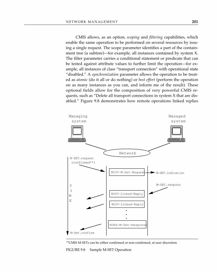
N E T W O R K M A N A G E M E N T 201
CMIS allows, as an option, scoping and filtering capabilities, whichenable the same operation to be performed on several resources by issu-ing a single request. The scope parameter identifies a part of the contain-ment tree (a subtree)—for example, all instances contained by system X.The filter parameter carries a conditional statement or predicate that canbe tested against attribute values to further limit the operation—for ex-ample, all instances of class “transport connection” with operational state“disabled.” A synchronization parameter allows the operation to be treat-ed as atomic (do it all or do nothing) or best effort (perform the operationon as many instances as you can, and inform me of the result). Theseoptional fields allow for the composition of very powerful CMIS re-quests, such as “Delete all transport connections in system X that are dis-abled.” Figure 9.8 demonstrates how remote operations linked replies
Network
Managingsystem
Managedsystem
M-SET.request(confirmed**)
M-Set.confirm
M-SET.indication
M-SET.respons
ROIV-M-Set-Request
ROIV-Linked-Reply
ROIV-Linked-Reply
RORS-M-Set-Response
TIME
•••
FIGURE 9.8 Sample M-SET Operation
**CMIS M-SETs can be either confirmed or non-confirmed, at user discretion
might be used by CMIP to return the results of such an operation, onereply per managed object instance (linked replies and parent-child opera-tions are discussed in Chapter 10). In the figure, a managing system callsupon a managed system to perform the sequence of change operationsassociated with the M-SET.request “delete transport connections in yoursystem that are disabled.” A single CMIS request is transferred by invok-ing remote operations. The M-SET.request is conveyed in a remote opera-tions packet (in the figure, the ROIV-M-Set-Request packet). As theagent at the managed system deletes each transport connection (eachmanaged-object instance), a successful result is returned using remoteoperations linked replies (in Figure 9.8, one ROIV-Linked-Reply pack-et would be returned for each deleted managed-object instance). Thecompletion of the management operation would be signaled back to themanaging system by the arrival of a remote operations (successful) resultpacket (in Figure 9.8, the RORS-M-Set-Response).
CMIS scoping and filtering provide capabilities that go beyondthe “all-powerful” SNMP GetNext but have been criticized as
costly to implement and support. This is one example of a key philosophical dif-ference between the authors of SNMP and CMIP—SNMP places the burden ofmanagement operations on the network management station, whereas CMIPallows for distribution of the load between manager and agent. It is important tonote that CMIP does not require load distribution—it can be implementedwithout scoping or filtering capability. Further, it can be argued that scopingand filtering must be provided for somewhere and that providing this capabilityas part of the management protocol simplifies management application develop-ment and reduces network management traffic. With SNMP, the managementapplication issues many GetNext messages, sifts through the results, and figuresout what is really of interest; with CMIP, the management application issues asingle scoped M-GET, and the agent does the sifting, returning only the inter-esting stuff. Finally, it is impossible to provide the same semantics without scop-ing and filtering—attribute values change, and testing them as close to theresource as possible minimizes (but does not eliminate) temporal flux.
System management functions (SMFs) provide tools—protocols andmanaged object classes—to implement routine management tasks com-mon to many applications. The initial batch of SMFs, published in late1991, provide the following services:
• The Object-Management Function (ISO/IEC 10164-1: 1991) provides
✧AHA✧
O P E N S Y S T E M S N E T W O R K I N G : T C P / I P A N D O S I202
SystemManagementFunctions
N E T W O R K M A N A G E M E N T 203
pass-through services corresponding to all CMIS operations,8
and a few common notifications: attributeValueChange,objectCreation, and objectDeletion. These notifications aredefined in ISO/IEC 10165-2: 1991 and appear in many GDMO-stylemanaged object classes.
• The State Management Function (ISO/IEC 10164-2: 1991) providesa few common state attributes and a common notification that canbe used to signal changes in state. For example, most resources canbe operational or disabled, some allow administrative control overuse of the resource, and some can tell whether or not they are inuse. The SMF allows this information to be represented in the sameway, in any managed object class, allowing common managementapplications to be developed to monitor and manage the status ofany resource.
• The Attributes For Representing Relationships Function (ISO/IEC10164-3: 1991) provides common relationship attributes and a changenotification that allow the interrelationship between managed ob-ject classes and instances to be captured in a consistent manner.
• The Alarm-Reporting Function (ISO/IEC 10164-4: 1991) defines com-mon notifications to signal faults detected by the agent system.Again, common representation of this information facilitates devel-opment of common fault monitoring applications.
• The Event Report Management Function (ISO/IEC 10164-5: 1991) andlog control function (ISO/IEC 10164-6: 1991) allow managers to con-trol which notifications will be sent as CMIS M-EVENT-REPORTsor logged by the agent system.
Many other SMFs are currently available or under development,including those aimed at security, performance, and accounting manage-ment. For example, Objects and Attributes for Access Control (ISO/IEC10164-9: 1991) allows security to be provided at the management objectclass, instance, and even operation level.
The event report and log control functions enable manager controlby using object-oriented techniques. For example, the event report man-agement function allows a manager to turn event forwarding on or off ortemporarily suspend it, to specify primary and backup destinations to
8. Basing management applications and agents on the object management function(OMF) pass-through services is intended to insulate them from the underlying protocol(CMIP) and therefore allow substitution (for example, to use a local RPC mechanisminstead). In practice, it turns out that there is another big advantage to using OMF insteadof CMIS—OMF allows an implementation to conform to only the agent “half” of CMIS,whereas CMIP requires support for both roles.
which the events should be sent, to indicate dates and times duringwhich forwarding should be enabled, and to specify detailed filters thatcan be used to selectively forward only a few events. Similarly, the logcontrol function allows control over logging of notifications at the agentsystem, for subsequent retrieval by the manager.
Another key philosophical difference between OSI and Internetmanagement is event handling. As mentioned previously,
SNMP uses (but does not rely upon) trap-directed polling, in which only afew critical events are detected by the SNMP agent, to be supplemented by peri-odic or trap-initiated polling by the SNMP NMS. On the other hand, OSI mightbe considered event-driven (recall that CMIP operates over a transport connec-tion; hence, the delivery of events is reliable). GDMO-based managed objectclasses tend to be defined with a number of notifications intended to signalchanges in the resource. The event report and log control functions provide man-agement control over forwarding and logging so that every little notificationdoesn’t end up being transmitted or stored. The end result is enormous flexibilityfor managers and thus for the management application—network or systemadministrators can pick and choose what they want to poll for and what theywant to be notified about. And—you guessed it—an enormous cost for theagent, which must detect, filter, throw away, store, and/or forward these notifi-cations. Cost can be reduced by clever implementations that propagate filter cri-teria back into the resources themselves and pragmatic MIB design (use condi-tional packages to allow implementation flexibility, avoid notifying about any-thing and everything you can think of ). Finally, it is possible to use CMIP in apolling mode, without being event-driven. In fact, most initial implementationsof CMIP did just this, for the sake of simplicity—and because the event reportand log control functions (ISO/IEC 10164-5: 1991; ISO/IEC 10164-6: 1991)were completed after CMIP (ISO/IEC 9596-1: 1990).
It is impossible to conclude any discussion of OSI without mentioninginternational standardized profiles (ISPs) for CMIP. International standard-ized profiles identify a collection of base standards, select options con-tained within the standards, and specify pragmatic constraints (for ex-ample, limiting field lengths; see Chapter 2). Because OSI standards arelayered and have so many options, ISPs are necessary to enable vendorsand users to build and buy products that can interoperate. For OSI man-agement, final ISPs are available for CMIP, and draft ISPs are availablefor the system-management functions. For example, the Enhanced Man-agement Communication profile (ISO/IEC 11183-3: 1992) specifies detailed
✧AHA✧
O P E N S Y S T E M S N E T W O R K I N G : T C P / I P A N D O S I204
Profiles
requirements for CMIP, ROSE, ACSE, presentation, and session proto-cols. The Basic Management Communication profile (ISO/IEC ISP 11183-3:1992) specifies similar requirements but excludes scoping and filteringfeatures. Any vendor providing a CMIP-based product today can beexpected to claim conformance to one or both of these profiles.
Putting It All TogetherHaving discussed the capabilities that Internet and OSI managementASEs have to offer, it is certainly appropriate to mention that, by andlarge, network and systems administrators really don’t care a whit aboutmanagement paradigms, robustness, elegance, or which “ASE” they use(if, in fact, they even know what an ASE is). They care about managingtheir enterprise. Today more than ever before, it is vital to provide“plug-and-play” technologies that work together to solve customer prob-lems. Some of the strategies that have thus far been developed for inte-gration, coexistence, and migration of management technologies arementioned in the following subsections.
Over the past few years, there have been several attempts to “bridge thegap” between CMIP and SNMP, including the following:
• CMIP for TCP/IP-based internets (RFC 1095) was originally intendedas a long-term management solution for the Internet. CMOTdefined the use of CMIP/ROSE/ACSE over a specialized versionof the OSI presentation layer (RFC 1085) over TCP/IP. Thisapproach has since been discarded by the Internet community fol-lowing a network-management “bake-off.”
At a point during the parallel development of SNMP andCMOT at which no further progress could be made in commit-
tee, the SNMP and CMOT camps decided to end the debate with a bake-off. Itwas jointly agreed that following several months of development, the implemen-tation worthiness of the two proposals would provide the final input. Accordingto Internet folklore, the SNMP camp was able to demonstrate multiple, interop-erable implementations, and the CMOT camp had none.
• More recently, the IETF considered a full-blown CMIP for theInternet (RFC 1189), which would eventually obsolete the original
✧AHA✧
N E T W O R K M A N A G E M E N T 205
Mix-and-MatchProtocols: SNMPover Foo, CMIPfor the Internet
CMOT effort. This approach glued the entire OSI CMIP upper-layerstack (down through session) onto TCP/IP using RFC 1006. AGDMO-based version of the Internet MIB II, called the OIM MIB II(RFC 1214) was to be developed. This MIB was intended to allowmanagement of Internet resources using CMIP protocols. Thisactivity came under IESG review in the spring of 1992, and theworking group was disbanded due to inactivity. Members of theX/Open and OSI Network Management Forum expect to produce aCMIP over TCP/IP using RFC 1006 as described earlier; however,RFC 1214 will be abandoned in favor of the CMIP profiles men-tioned in the preceding subsection.
• “SNMP over OSI” (RFC 1418) and, more recently, “SNMP over Foo”(read “anything”) RFCs have been developed by the IETF to glueSNMP over non-UDP/TCP transport technologies. This approachallows a single management protocol (SNMP) to be used in virtual-ly any networking environment. The MIBs are different from thosedeveloped for CMIP, but for multiprotocol networks, and for thoseconfigurations where SNMP agents cannot be reached using UDP,these extensions are expected to serve the Internet community quitewell.
• Although little standards activity is involved, CMIP network man-agement systems vendors, cognizant of the market availability ofcommunications equipment that supports SNMP agents, havedeveloped proxy elements in their CMIP-based products to gatherinformation and alarms from SNMP agents and integrate them intothe management capabilities they offer.
It is possible, and in some circumstances, quite pragmatic, to offer “dual-stack” products, which provide for concurrent application use of morethan one technology (OSI and TCP/IP). In fact, “dual stack” is increasinglybecoming “multistack,” in which supporting technologies are not limitedto Internet and OSI protocols but include RPC-based communication envi-ronments and the like. When more than one technology is used, applica-tions can be insulated from this fact by using a common, transparent appli-cation programming interface (API). For example, the X/Open managementprotocols API provides programmatic interfaces to both SNMP and CMIPand makes some attempt at limited transparency, at least for services thatare common to both management protocols—for example, anmp_get_request “C” function call is provided that can initiate an SNMPGet message, a CMIS M-GET.request, or perhaps even a local RPC query.
O P E N S Y S T E M S N E T W O R K I N G : T C P / I P A N D O S I206
Dual-StackApproach: HideIt Under the API
N E T W O R K M A N A G E M E N T 207
Unfortunately, the way in which a MIB is defined often precludesapplication transparency—for example, a MIB that uses CMIS M-ACTIONcannot be managed using SNMP unless it has been translated to anInternet SMI-style MIB and a gateway function is built to map between thetwo MIBs below the level of the API. This approach is currently undergoingspecification and development by consortia such as X/Open and theOSI/NM Forum.
Like most tools, network management isn’t very useful if it’s not de-ployed. As a practical consideration, the authors and advocates of SNMPcarefully guarded the protocol and management framework against thesort of meddling that caused the OSI common management effort tobecome bogged down in definition so that it could be widely deployedas quickly as possible. The advent of the secure SNMP enhancements,however compatible with the present SNMP standards, clearly called forrevisions to existing implementations. This posed a problem of no smallmeasure to the SNMP community: there were other minor deficienciesthat the Internet community would eventually wish to address, and thethought of two revisions and accompanying transitions was, to say theleast, troublesome. Following a March 1992 IESG call for contributionson the future of network management for the Internet, a proposal for aSimple Management Protocol was presented to the IETF in August 1992.The proposal, currently a set of seven Internet drafts, provides a strategyfor coexistence with the current SNMP, addresses some of the identifiedweaknesses of the SNMP framework, and claims to improve SNMP per-formance. SMP uses the secure SNMP enhancements but, as an out-growth of implementation experience, it has exposed and consequentlysolved some operational problems encountered. (The result is that SMPimplementations deviate from the secure SNMP RFCs, and the changesthe SMP introduces to secure SNMP are now under consideration in theIETF; once approved, the secure SNMP RFCs will be made historical,and there will be only one transition for internetwork management; i.e.,from SNMP version 1 to the eventual SMP/SNMPv2 RFCs.)
The more visible SMP enhancements to the SNMP include a changein the composition of the Trap message (it is now identical in structure tothe other SNMP data units). A new message type, dubbed the “awe-some” GetBulk operator, improves the way an SNMP manager retrieveslarge numbers of managed objects. A large set of error codes has beenidentified to improve exception reporting. Transport mappings of theSMP onto OSI, AppleTalk, and Novell/IPX as well as the recommendedUDP are provided. There are also a considerable number of changes to
On the Horizon:SimpleManagementProtocol (SMP) . . .or Is That“SNMPv2”?
O P E N S Y S T E M S N E T W O R K I N G : T C P / I P A N D O S I208
the structure of management information, including some new datatypes (enumerated BITSTRING and 64-bit counters, an OSI networkaddress data type). Finally, and notably, an Inform Request message hasbeen introduced, with an accompanying MIB, to be used for manager-to-manager communications; the InformRequest-PDU can be used as anacknowledged event notification and to transfer information betweennetwork management stations. Network management stations can thusoperate in a dual role—manager of resources as well as a resource or sub-ordinate to other NMSs. A very fortuitous side effect of the timing of theintroduction of SMP is that extensions for security, as well as improve-ments both desired and necessary, can be incorporated into existingimplementations in a single version change, and with a well-definedcoexistence plan.
During recent deliberations about SMP, an IETF memberpreferring anonymity suggested that SMP “is kinda like a
datagram version of CMIP, but without scoping and filtering.” Indeed, SMPseems to have addressed many of the much-ballyhooed shortcomings and defi-ciencies, and it will likely refuel the SNMP versus CMIP fire. If the existingbase of SNMP agent implementations can be upgraded quickly, and the claims ofimproved and more robust functionality are warranted, SMP as SNMP version2 will extend the market lead it currently holds over CMIP. Given that transportmappings are provided to allow SNMP to operate over OSI, AppleTalk, andNovell/IPX, and taking into consideration the practical difficulties of managinga multiprotocol Internet, the argument that there exists a single managementframework to manage all aspects of a diverse Internet may be a bit prematureand somewhat overstated, but it remains compelling.
Where To from Here?Most of the attention paid to network management is focused on themanagement protocols—SNMP and CMIP—and frameworks. However,if you ask a network administrator about products based on these proto-cols, you will find that although having standard protocols for networkmanagement is important, daily operations staff are still concerned thatmany aspects of network operations remain unattended, and networkadministrators will quickly tell you that reachability programs like ping,traceroute, netstat, and similar utilities continue to be important compo-nents of daily network operations.
✧AHA✧
N E T W O R K M A N A G E M E N T 209
The UNIX ping command uses the echo request datagram of theInternet control message protocol (ICMP; see Chapter 13) to evoke anecho reply datagram from a designated host on a TCP/IP network. It isby far the most commonly used fault-isolation tool. Ping provides ameans of determining whether a host is “IP-reachable” and is useful forobtaining (a coarse measure of) round-trip times; many network man-agement stations use ping in an automated fashion to monitor networkconnectivity.9 An OSI version of echo/ping is described in RFC 113910
and will be incorporated as two new packet types (request and reply) inthe second edition of ISO/IEC 8473, the OSI Connectionless Network LayerProtocol (CLNP; see Chapter 13), providing OSI network operations folkswith a tool whose features are equivalent to the ICMP-based ping.
Traceroute is a program that determines the route an IP packetwould follow from a source to a designated host by issuing a series ofuser datagram protocol (UDP) packets directed to a bogus destinationport and with the internet protocol “time to live” set to intentionally smallvalues, to elicit error messages from gateways that are attempting to for-ward the UDP packet. A gateway that receives the UDP packet but cannotforward it because its time to live has expired must return an ICMP errormessage “time exceeded.” From these messages, the traceroute programconstructs a list of gateways that comprise the route between the senderand the destination. The “probes” begin with a time to live of 1 andincrease by 1 until an ICMP message “port unreachable” is returned, indi-cating that the host has been reached, but the specified port is an incorrectone. Traceroute is an effective diagnostic tool for network operations; acompanion OSI traceroute program has been developed by members ofthe Network OSI Operations (NOOP) group within the IETF.
Network administrators are also quick to point out that there is toomuch effort directed at “managing everything that moves . . . ,” and MIBmania has left vendors with little alternative but to continue to focustheir efforts on the development of new MIBs. At the agent level, MIBmania increases the management burden; equally problematic is thatadditional MIB development in network management applications isperformed at the expense of creating better diagnostic aids and applica-
9. It is interesting to note that in the manual pages of some UNIX OSs, automatingping is discouraged; for example, the manual page for ping that accompanies theMACHTen UNIX® system from Tenon Intersystems says ping “should be used primarilyfor manual fault isolation. Because of the load it could impose on the network, it is unwiseto use ping during normal operations or from automated scripts.”10. This RFC is soon to be obsoleted; the replacement RFC will eliminate one of the twoelective ways to ping and align exactly with the ISO standard.

O P E N S Y S T E M S N E T W O R K I N G : T C P / I P A N D O S I210
tions that “heal” networks without manual intervention. There is alsoaltogether too much effort directed at simply presenting information tonetwork administrators in the jazziest manner; graphic user interfacesaside, most of the network management systems today offer little to sim-plify the task of managing. SNMP and CMIP can provide solicited eventsor traps, but all too often, a human must still intervene to identify andsolve the underlying real-world problem. Tools now exist to measurenetwork utilization, but more and better tools are needed to assist in net-work analysis and capacity planning and provisioning.
If you are in network operations, before getting all worked upabout which protocol you use, be forewarned: you won’t be giving upyour pager any time soon.
A closing commentary on SNMP versus CMIP: It should beapparent that entirely different perspectives and mind-sets
drove and still drive SNMP and CMIP. CMIP is to a large extent telephony-drivenand based on a telco view of the composition of packet and fast-packet networks.This view is inherited in part from telephony operations and managing voiceconnections. In this view, switching systems are comprised of two components:the switching or network elements and computers that are used to managegroups of network elements, called supervisory systems. Supervisory systemsare themselves managed by yet another and typically more centralized tier ofoperations systems. In this environment, the OSI common managementframework is imposed between the supervisory and operations systems (the man-agement framework and protocol used between supervisory systems and networkelements is often proprietary). The popular term for this is management ofmanagers. In theory, the network elements—the equivalent of routers andbridges of the public networks—don’t bear the burden of CMIP/CMIS (in prac-tice, counting and reporting often take their toll). From this example, it can beseen that advocates of OSI common management may have based their frame-work on the assumption that the managed resources themselves do an awful lotof management. In SNMP, which was developed with a datagram internetwork-ing paradigm in mind, there is an assumption that management is not the prin-cipal function of the managed resource—routers, bridges, and hosts all have betterthings to do with their CPU/links/memory than manage themselves, and somanagement overhead for these resources should be small (in fact, it can beargued that left to manage themselves, they would inevitably miss the bigger pic-ture of the network and screw up). Is this insight enough to appreciate the differ-ences? Hardly enough to fully appreciate them, but enough to start.
✧AHA✧
M A N A G E M E N T A P P L I C A T I O N S E R V I C E E L E M E N T S 211
ConclusionThis chapter has compared the “simple” network management frame-work for the Internet to OSI’s “common” management approach. BothSNMP and CMIP base services on interactions between a manager andits agents and, by extension, interactions between managers. Both modelmanagement information in an object-oriented fashion and use abstractsyntax notation one for object typing, identification, and encoding. Thesimilarities end there. Through examples, the authors demonstrated thatthe management paradigms of SNMP and CMIP are vastly different andshowed how SNMP attempts to place the burden of network manage-ment on the managing side, while CMIP distributes the burden betweena manager and its agents. It was suggested that this difference is partlyattributable to what the Internet (traditionally and decidedly a data com-munity) and OSI (strongly influenced by the telephony community) inter-pret as managed network resources. Finally, the chapter called readers’attention to the fact that even after one decides which management frame-work is best for his or her networking environment, there are other,equally important management tools to consider and briefly describedwhat TCP/IP and OSI offer as management instrumentation to comple-ment network management protocols.
10 “CORE” APPLICATION SERVICE ELEMENTS
Open any toolbox—irrespective of whether it belongs to a plumber, acarpenter, an electrician, or an automobile mechanic—and you will finda common, or “core,” set of tools: subtleties aside, a pair of pliers, a screw-driver, and a wrench are useful and necessary tools, whether the applica-tion is plumbing, carpentry, electrical work, or automotive repair. In gen-eral, distributed applications also rely on a set of core capabilities; i.e.,service elements that provide:
• The ability to initiate and terminate communications across a net-work (in this case, the OSI networking environment) and to ascer-tain prior to attempting to transmit data that the called applicationhas all the facilities and capabilities required to interpret and oper-ate on the data about to be sent. In OSI, the association control serviceelement (ACSE) provides these capabilities.
• The ability to structure conversations between distributed applica-tions (for example, providing the ability for applications operatingover a full-duplex connection to “take turns”) and the ability for anapplication to recover from disruption of underlying communica-tions services without loss of data (for example, providing the abilityfor peer applications to indicate “Yes, I heard what you said up tothe point where we were disconnected, and I’ve committed it tomemory [written it down]”). In OSI, the reliable transfer service ele-ment (RTSE) provides application access to the complement of dia-logue control capabilities offered in OSI: activity and turn manage-ment, synchronization, and resynchronization.
• The ability to perform functions at remote computers (remote oper-
213
O P E N S Y S T E M S N E T W O R K I N G : T C P / I P A N D O S I214
ations, remote procedure calls). In OSI, the remote operations serviceelement (ROSE) enables an application operating at one computer torequest or direct an application operating at a second computer (ormultiple computers) to share part of the processing burden. Con-ceptually, a remote operation might say, “Do this for me andinform me of the result when you’ve completed the task,” or “Dothis for me while I go off and do something equally important.Don’t interrupt me unless something goes wrong.”
These application service elements are the nucleus of an OSI appli-cation tool kit. (Readers are left with the exercise of determining whichapplication service element corresponds to the pair of pliers, the screw-driver, and the wrench.)
Identifying only these application service elements as “core”elements is admittedly subjective. OSI tried to do so formally
in the early stages of application layer standardization and failed because no con-sensus could be reached. In theory, the set of basic application service elements isopen-ended; many others—notably, commitment, concurrency, and recovery(CCR); remote database access (RDA); and message handling—might eventuallybe included. Association control, reliable transfer, and remote operations, however,are likely to be included in nearly everyone’s view; the treatment of “core” appli-cation service elements in this chapter, then, represents a minimalist’s view.
Association-Control Service ElementThe association control service element is included in all application con-text specifications1 and is used to form a connection (called an association)between application entities. In fact, the facilitating aspects of establishingan association—notably, the exchange of naming information (especiallyapplication entity titles) and negotiation of the facilities that the commu-nicating applications will need in order to communicate—are ACSE’sprimary role.
It is useful to continue with the analogy of association control’splaying the role of a facilitator in OSI application-to-application commu-
✧AHA✧
1. Technically speaking, the ACSE service definition strongly suggests this, stating that“it is expected that the ACSE will be included in all application context specifications”(ISO/IEC 8649: 1988). The OSI application layer structure standard (ISO/IEC 9545: 1989),written a year later, states that the ACSE “is a necessary part of AEs.” The reason for thisambiguity is revealed in a later discussion of modes of ACSE operation.
nications. In creating an application association, the association controlservice element truly facilitates a conference session; it identifies:
• Who will be talking (which application entities)• What subjects will be discussed (which application service ele-
ments)• The language(s) that will be spoken during the conference session
(what abstract syntaxes will be exchanged)• The “props” required for the conference session (what the presen-
tation and session connections should look like)
Once it has established an association between two or more appli-cation entities, the association control service element fades into thebackground, reappearing only to assist in closing the conference session(and in extreme cases, to interrupt or cancel it).
The formal mechanisms for establishing an application association aredescribed in a service definition (ISO/IEC 8649: 1988) and a protocolspecificaiton (ISO/IEC 8650: 1988). There are four association control ser-vices: A-ASSOCIATE provides “connection” establishment, A-RELEASEprovides an orderly “disconnect,” and the A-P-ABORT and A-U-ABORTservices offer provider- and user-initiated disruptive “disconnects.”Formally speaking, in establishing an association, 30 parameters aredefined for the A-ASSOCIATE service. Simplified greatly, applicationentities use the parameters of the A-ASSOCIATE service primitives toidentify:
• Themselves• The application context required for this association• The presentation context required for this association• Presentation service requirements• Session service requirements
(The complete set of A-ASSOCIATE service parameters is presentedin Table 10.1.)
To invoke the service, an association control user (a.k.a. the re-quester) issues an A-ASSOCIATE.request primitive. The requester may beanother standard application service element or a user element. In thenormal mode of ACSE operation, association control uses some of the para-meters passed in this request to construct the A-ASSOCIATE.requestpacket (in Figure 10.1, the AARQ APDU); most of the parameters con-veyed in the AARQ APDU are identifiers. Application entities identifythemselves through the exchange of their names—their application entity
“ C O R E ” A P P L I C A T I O N S E R V I C E E L E M E N T S 215
The ACSEService andProtocol
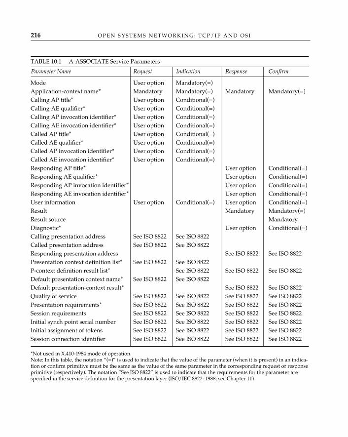
O P E N S Y S T E M S N E T W O R K I N G : T C P / I P A N D O S I216
TABLE 10.1 A-ASSOCIATE Service Parameters
Parameter Name Request Indication Response Confirm
Mode User option Mandatory(=)Application-context name* Mandatory Mandatory(=) Mandatory Mandatory(=)Calling AP title* User option Conditional(=)Calling AE qualifier* User option Conditional(=)Calling AP invocation identifier* User option Conditional(=)Calling AE invocation identifier* User option Conditional(=)Called AP title* User option Conditional(=)Called AE qualifier* User option Conditional(=)Called AP invocation identifier* User option Conditional(=)Called AE invocation identifier* User option Conditional(=)Responding AP title* User option Conditional(=)Responding AE qualifier* User option Conditional(=)Responding AP invocation identifier* User option Conditional(=)Responding AE invocation identifier* User option Conditional(=)User information User option Conditional(=) User option Conditional(=)Result Mandatory Mandatory(=)Result source MandatoryDiagnostic* User option Conditional(=)Calling presentation address See ISO 8822 See ISO 8822Called presentation address See ISO 8822 See ISO 8822Responding presentation address See ISO 8822 See ISO 8822Presentation context definition list* See ISO 8822 See ISO 8822P-context definition result list* See ISO 8822 See ISO 8822 See ISO 8822Default presentation context name* See ISO 8822 See ISO 8822Default presentation-context result* See ISO 8822 See ISO 8822Quality of service See ISO 8822 See ISO 8822 See ISO 8822 See ISO 8822Presentation requirements* See ISO 8822 See ISO 8822 See ISO 8822 See ISO 8822Session requirements See ISO 8822 See ISO 8822 See ISO 8822 See ISO 8822Initial synch point serial number See ISO 8822 See ISO 8822 See ISO 8822 See ISO 8822Initial assignment of tokens See ISO 8822 See ISO 8822 See ISO 8822 See ISO 8822Session connection identifier See ISO 8822 See ISO 8822 See ISO 8822 See ISO 8822
*Not used in X.410-1984 mode of operation.Note: In this table, the notation “(=)” is used to indicate that the value of the parameter (when it is present) in an indica-tion or confirm primitive must be the same as the value of the same parameter in the corresponding request or responseprimitive (respectively). The notation “See ISO 8822” is used to indicate that the requirements for the parameter arespecified in the service definition for the presentation layer (ISO/IEC 8822: 1988; see Chapter 11).
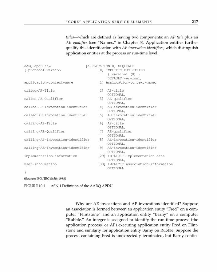
“ C O R E ” A P P L I C A T I O N S E R V I C E E L E M E N T S 217
titles—which are defined as having two components: an AP title plus anAE qualifier (see “Names,” in Chapter 5). Application entities furtherqualify this identification with AE invocation identifiers, which distinguishapplication entities at the process or run-time level.
AARQ-apdu ::= [APPLICATION 0] SEQUENCE{ protocol-version [0] IMPLICIT BIT STRING
{ version1 (0) }DEFAULT version1,
application-context-name [1] Application-context-name,
called-AP-Title [2] AP-titleOPTIONAL,
called-AE-Qualifier [3] AE-qualifierOPTIONAL,
called-AP-Invocation-identifier [4] AE-invocation-identifierOPTIONAL,
called-AE-Invocation-identifier [5] AE-invocation-identifierOPTIONAL,
calling-AP-Title [6] AP-titleOPTIONAL,
calling-AE-Qualifier [7] AE-qualifierOPTIONAL,
calling-AP-Invocation-identifier [8] AE-invocation-identifierOPTIONAL,
calling-AE-Invocation-identifier [9] AE-invocation-identifierOPTIONAL,
implementation-information [29] IMPLICIT Implementation-dataOPTIONAL,
user-information [30] IMPLICIT Association-informationOPTIONAL
}
(Source: ISO/IEC 8650: 1988)
FIGURE 10.1 ASN.1 Definition of the AARQ APDU
Why are AE invocations and AP invocations identified? Supposean association is formed between an application entity “Fred” on a com-puter “Flintstone” and an application entity “Barny” on a computer“Rubble.” An integer is assigned to identify the run-time process (theapplication process, or AP) executing application entity Fred on Flint-stone and similarly for application entity Barny on Rubble. Suppose theprocess containing Fred is unexpectedly terminated, but Barny contin-
O P E N S Y S T E M S N E T W O R K I N G : T C P / I P A N D O S I218
ues. When Fred is resurrected as a new run-time process, new invocationidentifiers are assigned so that in subsequent communications, Barnywill know that it is communicating with a different process than beforeand hence can determine that the interruption in communication wasdue to a run-time process failure at Flintstone. Conversely, if communi-cation between Fred and Barny is interrupted, and both processes contin-ue, once communication is restored between Flintstone and Rubble, bothapplication entities will be able to recognize that they are communicatingwith the same invocation of their peer.
A singularly important parameter passed in the A-ASSOCIATE.re-quest primitive is the application context name. The application contextname identifies the set of application service elements required by thedistributed application initiating this communication.
The information passed to ACSE in the A-ASSOCIATE. requestprimitive is used to construct a corresponding A-ASSOCIATE request pro-tocol data unit. The ASN.1 definition of this PDU is given in Figure 10.1.
An application that uses the directory system protocol (described inChapter 7), for example, uses the association control service element and aset of defined remote operations. The application context directorySys-temAC that describes this is “named” by the OBJECT IDENTIFIER id-ac-directorySystemAC; the ASN.1 definition for this application con-text is:
directorySystemACAPPLICATION-CONTEXTAPPLICATION SERVICE ELEMENTS {aCSE}BIND DSABindUNBIND DSAUnbindREMOTE OPERATIONS {rOSE}OPERATIONS OF {chainedReadASE, chainedSearchASE,chainedModifyASE}ABSTRACT SYNTAXES {id-as-acse, id-as-directorySystemAS}::= {id-ac-directorySystemAC}
Thus, when creating an association between two (directory) appli-cation processes that wish to use the directory system protocol, the re-questing application entity assigns the information object applica-tion-context-name (one of the data in the AARQ APDU, shown inFigure 10.1) the value of the OBJECT IDENTIFIER id-ac-directorySystemAC. Using the application context name, the called applicationentity determines the set of application service elements that must beavailable to support this distributed application.
The requester also identifies the abstract syntaxes (modules of
“ C O R E ” A P P L I C A T I O N S E R V I C E E L E M E N T S 219
ASN.1 “code”; note that this, too, is derived from the application con-text), the presentation services that are required, and the presentationaddress of the called association-control user (a.k.a. the “accepter“) in theA-ASSOCIATE.request primitive. These parameters are not conveyed toa remote association control “peer” using the association control proto-col. They are submitted in the A-ASSOCIATE.request by the requester sothat the association control service provider can make appropriaterequests when establishing a presentation connection to support the dis-tributed application; they are used to compose a P-CONNECT.requestprimitive (see Chapter 11).
Why should the association control service user have knowl-edge of both the presentation and session service requirements,
and why must these be indicated in an A-ASSOCIATE.request? Part of the rea-son lies in the parallel development of the CCITT X.400 Message HandlingSystem recommendations and the OSI upper layers. CCITT had developed mes-sage handling standards with the understanding that the T.62 protocol devel-oped for teletex would be used at the session layer. What Marshall Rosedescribes in a “soapbox” as “largely hysterical reasons” were simply political:accommodating the perceived (exaggerated) “embedded base” of teletex termi-nals in X.400 was considered “strategic,” and T.62 functions were effectively“grandfathered” into the OSI session layer, rendering moot any argument aboutcorrect placement of these functions elsewhere.
What would have been a “correct” solution? There are at least two schoolsof thought on this subject: (1) the session and presentation functions are in thewrong layers and should have been identified as application layer functions inthe first place, perhaps to the extreme of eliminating the session layer entirely;and (2) the functions of the upper layers are not inherently hierarchical, and acomplete rethinking of the upper layers was appropriate. In fact, aspects of bothschools of thought exist: the pass-through of presentation and session require-ments is a concession to the first school of thought (the application layer ulti-mately controls what goes on in the session layer, and where the protocol oper-ates is a formality) and the definition of application service elements in the OSIApplication Layer Structure standard is a concession to the second school ofthought (you have building blocks in the application layer).
Association control and presentation connection processing are“piggybacked”: the association control APDUs for A-ASSOCIATE, A-RELEASE, and A-U-ABORT are conveyed as user data in correspondingpresentation service primitives (P-CONNECT, P-RELEASE, and P-U-ABORT, respectively). The sequence of primitives and application proto-
✧AHA✧
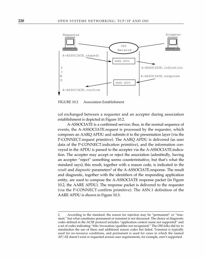
O P E N S Y S T E M S N E T W O R K I N G : T C P / I P A N D O S I220
col exchanged between a requester and an accepter during associationestablishment is depicted in Figure 10.2.
A-ASSOCIATE is a confirmed service; thus, in the normal sequence ofevents, the A-ASSOCIATE.request is processed by the requester, whichcomposes an AARQ APDU and submits it to the presentation layer (via theP-CONNECT.request primitive). The AARQ APDU is delivered (as userdata of the P-CONNECT.indication primitive), and the information con-veyed in the APDU is passed to the accepter via the A-ASSOCIATE.indica-tion. The accepter may accept or reject the association (admittedly, havingan accepter “reject” something seems counterintuitive, but that’s what thestandard says); this result, together with a reason code, is indicated in theresult and diagnostic parameters2 of the A-ASSOCIATE.response. The resultand diagnostic, together with the identifiers of the responding applicationentity, are used to compose the A-ASSOCIATE response packet (in Figure10.2, the AARE APDU). The response packet is delivered to the requester(via the P-CONNECT.confirm primitive). The ASN.1 definition of theAARE APDU is shown in Figure 10.3.
2. According to the standard, the reason for rejection may be “permanent” or “tran-sient,” but what constitutes permanent or transient is not discussed. The choice of diagnosticcodes defined in the ACSE protocol includes “application context name not supported” anda set of codes indicating “title/invocation/qualifier not recognized.” The OSI folks did try tostandardize the use of these and additional reason codes but failed. Transient is typicallyused for no-resource conditions, and permanent is used for cases in which the namedAP/AE doesn’t exist or requested session user requirements, for example, aren’t supported.
A-ASSOCIATE.request
A-ASSOCIATE.indication
A-ASSOCIATE.response
A-ASSOCIATE.confirm
TIME
AccepterRequester
OSINetwork
AARE APDU
AARQ APDU
FIGURE 10.2 Association Establishment
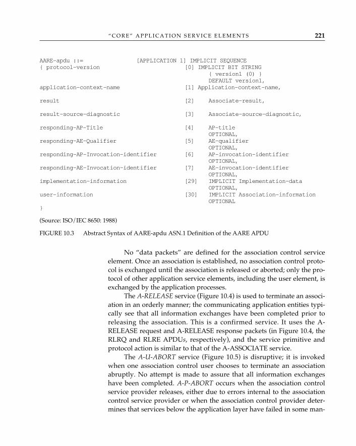
“ C O R E ” A P P L I C A T I O N S E R V I C E E L E M E N T S 221
AARE-apdu ::= [APPLICATION 1] IMPLICIT SEQUENCE{ protocol-version [0] IMPLICIT BIT STRING
{ version1 (0) }DEFAULT version1,
application-context-name [1] Application-context-name,
result [2] Associate-result,
result-source-diagnostic [3] Associate-source-diagnostic,
responding-AP-Title [4] AP-titleOPTIONAL,
responding-AE-Qualifier [5] AE-qualifierOPTIONAL,
responding-AP-Invocation-identifier [6] AP-invocation-identifierOPTIONAL,
responding-AE-Invocation-identifier [7] AE-invocation-identifierOPTIONAL,
implementation-information [29] IMPLICIT Implementation-dataOPTIONAL,
user-information [30] IMPLICIT Association-informationOPTIONAL
}
(Source: ISO/IEC 8650: 1988)
FIGURE 10.3 Abstract Syntax of AARE-apdu ASN.1 Definition of the AARE APDU
No “data packets” are defined for the association control serviceelement. Once an association is established, no association control proto-col is exchanged until the association is released or aborted; only the pro-tocol of other application service elements, including the user element, isexchanged by the application processes.
The A-RELEASE service (Figure 10.4) is used to terminate an associ-ation in an orderly manner; the communicating application entities typi-cally see that all information exchanges have been completed prior toreleasing the association. This is a confirmed service. It uses the A-RELEASE request and A-RELEASE response packets (in Figure 10.4, theRLRQ and RLRE APDUs, respectively), and the service primitive andprotocol action is similar to that of the A-ASSOCIATE service.
The A-U-ABORT service (Figure 10.5) is disruptive; it is invokedwhen one association control user chooses to terminate an associationabruptly. No attempt is made to assure that all information exchangeshave been completed. A-P-ABORT occurs when the association controlservice provider releases, either due to errors internal to the associationcontrol service provider or when the association control provider deter-mines that services below the application layer have failed in some man-
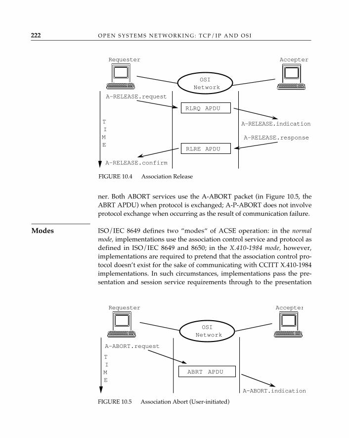
ner. Both ABORT services use the A-ABORT packet (in Figure 10.5, theABRT APDU) when protocol is exchanged; A-P-ABORT does not involveprotocol exchange when occurring as the result of communication failure.
ISO/IEC 8649 defines two “modes“ of ACSE operation: in the normalmode, implementations use the association control service and protocol asdefined in ISO/IEC 8649 and 8650; in the X.410-1984 mode, however,implementations are required to pretend that the association control pro-tocol doesn’t exist for the sake of communicating with CCITT X.410-1984implementations. In such circumstances, implementations pass the pre-sentation and session service requirements through to the presentation
O P E N S Y S T E M S N E T W O R K I N G : T C P / I P A N D O S I222
Modes
FIGURE 10.5 Association Abort (User-initiated)
A-ABORT.request
A-ABORT.indication
ABRT APDU
TIME
AccepterRequester
OSINetwork
FIGURE 10.4 Association Release
A-RELEASE.request
A-RELEASE.indication
A-RELEASE.response
A-RELEASE.confirm
RLRQ APDU
TIME
AccepterRequester
OSINetwork
RLRE APDU
“ C O R E ” A P P L I C A T I O N S E R V I C E E L E M E N T S 223
layer and use only the presentation kernel (see Chapter 11). No associa-tion control protocol is exchanged; the mode of operation is conveyedduring the presentation connection establishment (see Chapter 11).
Only a handful of the parameters of the A-ASSOCIATE service areused in the case of X.410-1984 mode (those that are not marked with “*”in Table 10.1). The conformance statement for the association control pro-tocol says that either or both modes must be implemented.
The X.410-1984 mode of operation is named after the 1984version of the CCITT X.400 Message Handling System re-
commendations. The history behind the existence of two modes of ACSE opera-tion is simple. In 1983, the CCITT was in the process of completing its recom-mendations for message handling services; at the time, however, the dispositionof function between the application and presentation layers of the message han-dling architecture was still a subject of great debate in the ISO OSI community.Since leap years were historically “publish or perish” times for CCITT—themember organizations had to agree upon recommendations during a plenarysession or wait another four years for the next plenary—it was determined thatthe best interests of the CCITT community would not be served by waiting forthe OSI upper layer organization to be completed. Applying the changesthroughout the MHS architecture could be done in 1988, with only the smallissue of “backward compatibility” to consider—and how hard could that be?
Reliable Transfer Service ElementThere are very few occasions when you have the luxury of reading abook uninterrupted, or “cover to cover.” More often than not, you findtime to read several pages, perhaps a chapter or two, but inevitably, yourreading time will be interrupted, or you’ll fall asleep. You might dog-earthe last page read or use a bookmark to locate the point where youshould continue when you once again find time to read. You do so be-cause you would certainly prefer to continue reading from the pagewhere you left off rather than begin again from page 1. In such situa-tions, you and the book have formed an association, and your use of abookmark, for example, provides a synchronization point (or “check-point”). Similarly, if you engage in a telephone conversation with some-one and your call is unexpectedly disconnected, you redial and typicallycontinue, or recover, the conversation from the point at which you wereinterrupted. Again, you and the party you call are engaged in a (voice)
✧AHA✧
O P E N S Y S T E M S N E T W O R K I N G : T C P / I P A N D O S I224
application, and your ability to remember the last subject under discus-sion serves as a synchronization point in the conversation in the eventthat the underlying telephone connection fails. In both examples, largeamounts of information are exchanged between communicating entities.And although the two forms of dialogue illustrated differ—the first ismonologue, the latter two-way alternate—there is a strong incentive inboth cases to avoid repetition.
End users of applications that exchange large amounts of data—multimedia message handling, image transfer/retrieval, office or elec-tronic document interchange, plain old bulk file transfer—share thisincentive; they don’t want to “start from scratch” if network connectionsfail. It wastes time and resources and is potentially costly. The reliabletransfer service element (RTSE) (ISO/IEC 9066-1: 1989; ISO/IEC 9066-2:1989) provides services that enable application entities to (1) synchronizeand later recover from (temporary) communications failures betweenend systems with a minimum amount of retransmission, and (2) conductboth monologue and two-way alternate conversations without having todeal directly with the mechanics of providing such services.
The reliable transfer service element relieves the user from havingto worry about the details of association establishment and release. Thisservice does not provide low-level control of associations the way thatassociation control does; rather, it initiates and terminates an associationfor a reliable transfer service user with the primary purpose of transfer-ring data. The reliable transfer service effectively bundles several layersof service features into a single service. Using the RTSE primitives, a reli-able transfer service user can:
• Coordinate information exchange within an association (turn man-agement)
• Confirm that a remote reliable transfer service user has receivedand secured data before sending more data (synchronization)
• Recover from the temporary loss of a presentation connection• Ensure that an association is closed without loss of any information
that might have been in transit when the close was requested (thepopular term for this mechanism is graceful close)
The foregoing can be accomplished with three simple service requests:RT-OPEN, RT-TRANSFER, and RT-CLOSE.
As an example, consider a medical-imaging service, one that en-ables physicians to retrieve X rays or magnetic resonance images (MRIs)from a central database across a network providing application-to-appli-cation throughput of 1 Mbps. MRIs are very large, measurable in mega-
bytes of data. In a worst-case scenario—all but the last 1,000-byte frag-ment of the image is transferred, and the network connection fails —retransmission of a 10-megabyte (80-megabits) MRI “from scratch” couldcause nearly 80 additional seconds of delay in the transfer. Now, a physi-cian’s time is precious, and such delays might not be tolerated. The reli-able transfer service could be used by this medical-imaging service ele-ment to assure that the precise image is delivered to the physician with-out excessive retransmission. In this example, retransmission couldbegin from the point of failure (the last 1,000 bytes), and the delay wouldbe greatly reduced.
The reliable transfer process, from request to completion of trans-fer, is composed of the functions discussed in the following sections.
A physician makes a request for an MRI from a remote image database.The user element of the remote image database application invokes theRT-OPEN service, which uses the Association-Control Service Element toform an association between the computer hosting the database and thephysician’s local computer (see Figure 10.6). Note that in this example, theinformation object .application-context-name of the AARQ APDUwould be assigned the OID value for the association context name of themythical MRI application “davesExcellentMRIs.” Since the origin andlocation of this name information are not obvious, let’s consider the exam-ple a bit further. Suppose “Dave’s Excellent Software” is a U.S.-based com-pany, and suppose further that the firm decides to obtain a globallyunique identifier from the U.S. registration authority (see Chapter 5). Theorganization identifier is given the alphanumeric representation of“davesExcellent” and assigned a numeric value of “22345.” When Dave’sExcellent Software develops the MRI application, it uses the branch of theobject identification tree iso (1) member-body (2) US (840)davesExcellent (22345) to uniquely identify application entities,abstract syntaxes, application context names, etc., for its applications.Thus, depending on how the company decided to write ASN.1 definitionsfor its applications, the application context name of the applicationdavesExcellentMRIs might look like this:
davesExcellent-MRIs-ac OBJECT IDENTIFIER::= { iso (1) member-body (2) US (840) davesExcellent (22345)
MRIs (01) applicationContext (03) }
This application context name identifies the user element3 and, by impli-
“ C O R E ” A P P L I C A T I O N S E R V I C E E L E M E N T S 225
AssociationEstablishment
3. The term user element refers to the consumer of ASE services. (ISO/IEC 7498-1: 1993).
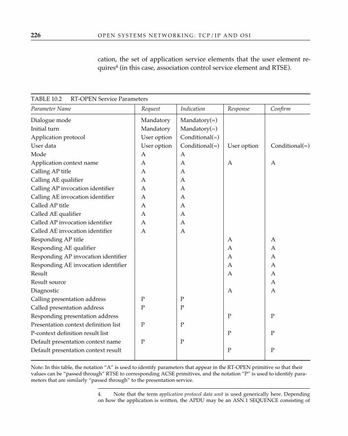
O P E N S Y S T E M S N E T W O R K I N G : T C P / I P A N D O S I226
cation, the set of application service elements that the user element re-quires4 (in this case, association control service element and RTSE).
TABLE 10.2 RT-OPEN Service Parameters
Parameter Name Request Indication Response Confirm
Dialogue mode Mandatory Mandatory(=)Initial turn Mandatory Mandatory(=)Application protocol User option Conditional(=)User data User option Conditional(=) User option Conditional(=)Mode A AApplication context name A A A ACalling AP title A ACalling AE qualifier A ACalling AP invocation identifier A ACalling AE invocation identifier A ACalled AP title A ACalled AE qualifier A ACalled AP invocation identifier A ACalled AE invocation identifier A AResponding AP title A AResponding AE qualifier A AResponding AP invocation identifier A AResponding AE invocation identifier A AResult A AResult source ADiagnostic A ACalling presentation address P PCalled presentation address P PResponding presentation address P PPresentation context definition list P PP-context definition result list P PDefault presentation context name P PDefault presentation context result P P
Note: In this table, the notation “A” is used to identify parameters that appear in the RT-OPEN primitive so that theirvalues can be “passed through” RTSE to corresponding ACSE primitives, and the notation “P” is used to identify para-meters that are similarly “passed through” to the presentation service.
4. Note that the term application protocol data unit is used generically here. Dependingon how the application is written, the APDU may be an ASN.1 SEQUENCE consisting of
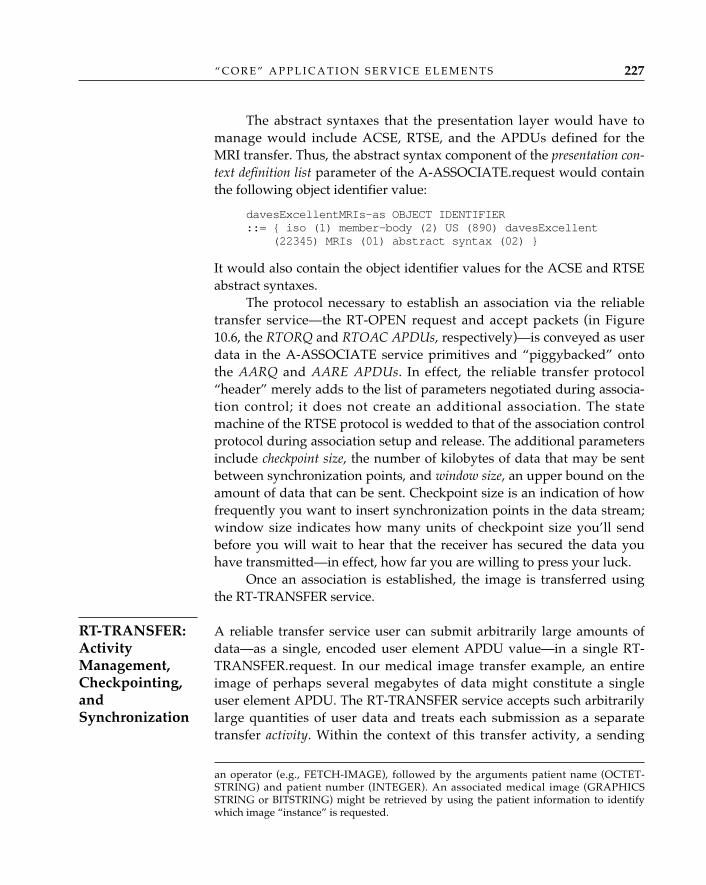
The abstract syntaxes that the presentation layer would have tomanage would include ACSE, RTSE, and the APDUs defined for theMRI transfer. Thus, the abstract syntax component of the presentation con-text definition list parameter of the A-ASSOCIATE.request would containthe following object identifier value:
davesExcellentMRIs-as OBJECT IDENTIFIER ::= { iso (1) member-body (2) US (890) davesExcellent
(22345) MRIs (01) abstract syntax (02) }
It would also contain the object identifier values for the ACSE and RTSEabstract syntaxes.
The protocol necessary to establish an association via the reliabletransfer service—the RT-OPEN request and accept packets (in Figure10.6, the RTORQ and RTOAC APDUs, respectively)—is conveyed as userdata in the A-ASSOCIATE service primitives and “piggybacked” ontothe AARQ and AARE APDUs. In effect, the reliable transfer protocol“header” merely adds to the list of parameters negotiated during associa-tion control; it does not create an additional association. The statemachine of the RTSE protocol is wedded to that of the association controlprotocol during association setup and release. The additional parametersinclude checkpoint size, the number of kilobytes of data that may be sentbetween synchronization points, and window size, an upper bound on theamount of data that can be sent. Checkpoint size is an indication of howfrequently you want to insert synchronization points in the data stream;window size indicates how many units of checkpoint size you’ll sendbefore you will wait to hear that the receiver has secured the data youhave transmitted—in effect, how far you are willing to press your luck.
Once an association is established, the image is transferred usingthe RT-TRANSFER service.
A reliable transfer service user can submit arbitrarily large amounts ofdata—as a single, encoded user element APDU value—in a single RT-TRANSFER.request. In our medical image transfer example, an entireimage of perhaps several megabytes of data might constitute a singleuser element APDU. The RT-TRANSFER service accepts such arbitrarilylarge quantities of user data and treats each submission as a separatetransfer activity. Within the context of this transfer activity, a sending
“ C O R E ” A P P L I C A T I O N S E R V I C E E L E M E N T S 227
an operator (e.g., FETCH-IMAGE), followed by the arguments patient name (OCTET-STRING) and patient number (INTEGER). An associated medical image (GRAPHICSSTRING or BITSTRING) might be retrieved by using the patient information to identifywhich image “instance” is requested.
RT-TRANSFER:ActivityManagement,Checkpointing,andSynchronization
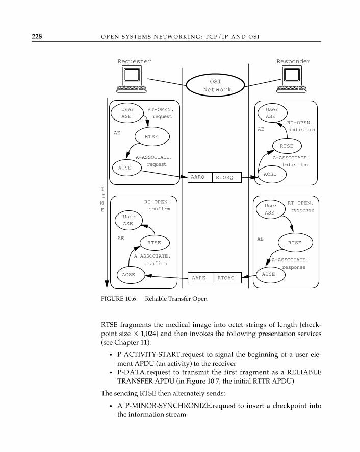
O P E N S Y S T E M S N E T W O R K I N G : T C P / I P A N D O S I228
RTSE fragments the medical image into octet strings of length {check-point size � 1,024} and then invokes the following presentation services(see Chapter 11):
• P-ACTIVITY-START.request to signal the beginning of a user ele-ment APDU (an activity) to the receiver
• P-DATA.request to transmit the first fragment as a RELIABLETRANSFER APDU (in Figure 10.7, the initial RTTR APDU)
The sending RTSE then alternately sends:
• A P-MINOR-SYNCHRONIZE.request to insert a checkpoint intothe information stream
FIGURE 10.6 Reliable Transfer Open
A-ASSOCIATE.request
ACSE
RT-OPEN.request
RTSE
ResponderRequester
OSINetwork
UserASE
AE
AARQ RTORQ
A-ASSOCIATE.indication
ACSE
RT-OPEN.indication
RTSE
UserASE
AE
TIME
A-ASSOCIATE.response
ACSE
RT-OPEN.response
RTSE
UserASE
AE
AARE RTOAC
A-ASSOCIATE.confirm
ACSE
RT-OPEN.confirm
RTSE
UserASE
AE
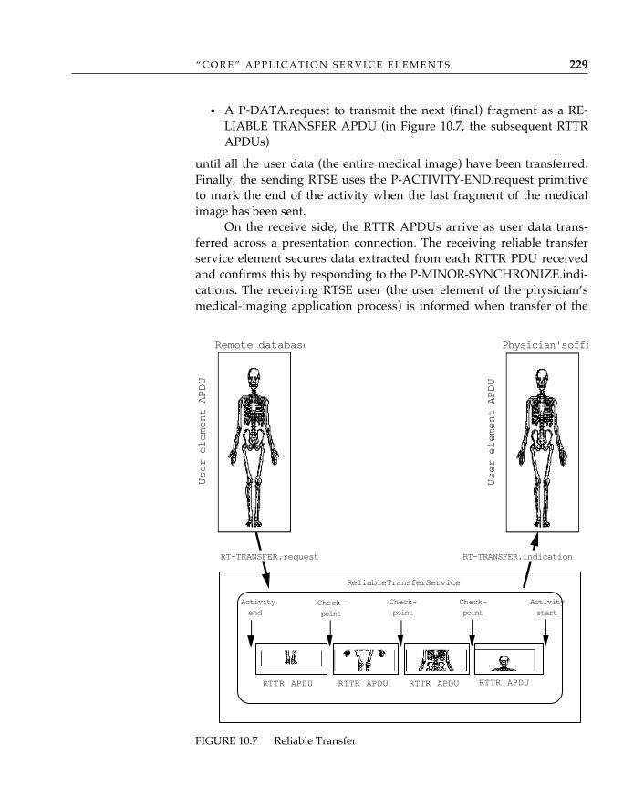
“ C O R E ” A P P L I C A T I O N S E R V I C E E L E M E N T S 229
• A P-DATA.request to transmit the next (final) fragment as a RE-LIABLE TRANSFER APDU (in Figure 10.7, the subsequent RTTRAPDUs)
until all the user data (the entire medical image) have been transferred.Finally, the sending RTSE uses the P-ACTIVITY-END.request primitiveto mark the end of the activity when the last fragment of the medicalimage has been sent.
On the receive side, the RTTR APDUs arrive as user data trans-ferred across a presentation connection. The receiving reliable transferservice element secures data extracted from each RTTR PDU receivedand confirms this by responding to the P-MINOR-SYNCHRONIZE.indi-cations. The receiving RTSE user (the user element of the physician’smedical-imaging application process) is informed when transfer of the
FIGURE 10.7 Reliable Transfer
RT-TRANSFER.request
User element APDU
Activity
start
Activity
endCheck-
point
RTTR APDURTTR APDU RTTR APDU RTTR APDU
RT-TRANSFER.indication
User element APDU
Reliable Transfer Service
Remote database Physician's offi
Check-
point
Check-
point
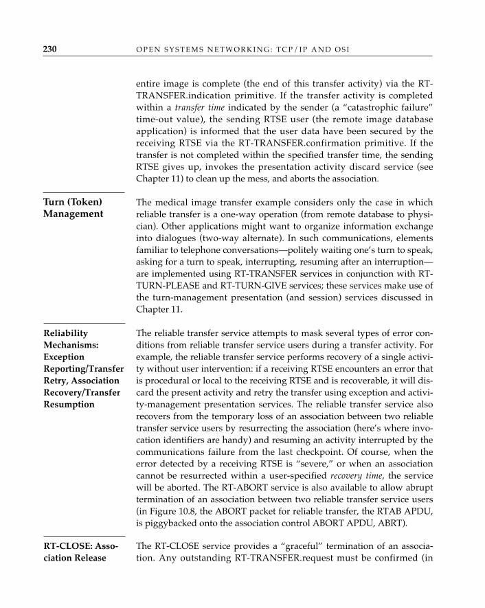
entire image is complete (the end of this transfer activity) via the RT-TRANSFER.indication primitive. If the transfer activity is completedwithin a transfer time indicated by the sender (a “catastrophic failure”time-out value), the sending RTSE user (the remote image databaseapplication) is informed that the user data have been secured by thereceiving RTSE via the RT-TRANSFER.confirmation primitive. If thetransfer is not completed within the specified transfer time, the sendingRTSE gives up, invokes the presentation activity discard service (seeChapter 11) to clean up the mess, and aborts the association.
The medical image transfer example considers only the case in whichreliable transfer is a one-way operation (from remote database to physi-cian). Other applications might want to organize information exchangeinto dialogues (two-way alternate). In such communications, elementsfamiliar to telephone conversations—politely waiting one’s turn to speak,asking for a turn to speak, interrupting, resuming after an interruption—are implemented using RT-TRANSFER services in conjunction with RT-TURN-PLEASE and RT-TURN-GIVE services; these services make use ofthe turn-management presentation (and session) services discussed inChapter 11.
The reliable transfer service attempts to mask several types of error con-ditions from reliable transfer service users during a transfer activity. Forexample, the reliable transfer service performs recovery of a single activi-ty without user intervention: if a receiving RTSE encounters an error thatis procedural or local to the receiving RTSE and is recoverable, it will dis-card the present activity and retry the transfer using exception and activi-ty-management presentation services. The reliable transfer service alsorecovers from the temporary loss of an association between two reliabletransfer service users by resurrecting the association (here’s where invo-cation identifiers are handy) and resuming an activity interrupted by thecommunications failure from the last checkpoint. Of course, when theerror detected by a receiving RTSE is “severe,” or when an associationcannot be resurrected within a user-specified recovery time, the servicewill be aborted. The RT-ABORT service is also available to allow abrupttermination of an association between two reliable transfer service users(in Figure 10.8, the ABORT packet for reliable transfer, the RTAB APDU,is piggybacked onto the association control ABORT APDU, ABRT).
The RT-CLOSE service provides a “graceful” termination of an associa-tion. Any outstanding RT-TRANSFER.request must be confirmed (in
O P E N S Y S T E M S N E T W O R K I N G : T C P / I P A N D O S I230
Turn (Token)Management
ReliabilityMechanisms:ExceptionReporting/TransferRetry, AssociationRecovery/TransferResumption
RT-CLOSE: Asso-ciation Release
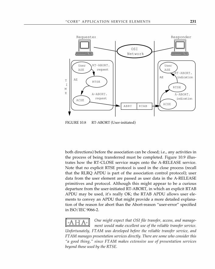
“ C O R E ” A P P L I C A T I O N S E R V I C E E L E M E N T S 231
both directions) before the association can be closed; i.e., any activities inthe process of being transferred must be completed. Figure 10.9 illus-trates how the RT-CLOSE service maps onto the A-RELEASE service.Note that no explicit RTSE protocol is used in the close process (recallthat the RLRQ APDU is part of the association control protocol); userdata from the user element are passed as user data in the A-RELEASEprimitives and protocol. Although this might appear to be a curiousdeparture from the user-initiated RT-ABORT, in which an explicit RTABAPDU may be used, it’s really OK; the RTAB APDU allows user ele-ments to convey an APDU that might provide a more detailed explana-tion of the reason for abort than the Abort-reason “user-error” specifiedin ISO/IEC 9066-2.
One might expect that OSI file transfer, access, and manage-ment would make excellent use of the reliable transfer service.
Unfortunately, FTAM was developed before the reliable transfer service, andFTAM manages presentation services directly. There are some who consider this“a good thing,” since FTAM makes extensive use of presentation servicesbeyond those used by the RTSE.
✧AHA✧
FIGURE 10.8 RT-ABORT (User-initiated)
A-ABORT.request
ACSE
RT-ABORT.request
RTSE
ResponderRequester
OSINetwork
UserASE
AE
ABRT
A-ABORT.indication
ACSE
RT-ABORT.indication
RTSE
UserASE
AETIME
RTAB
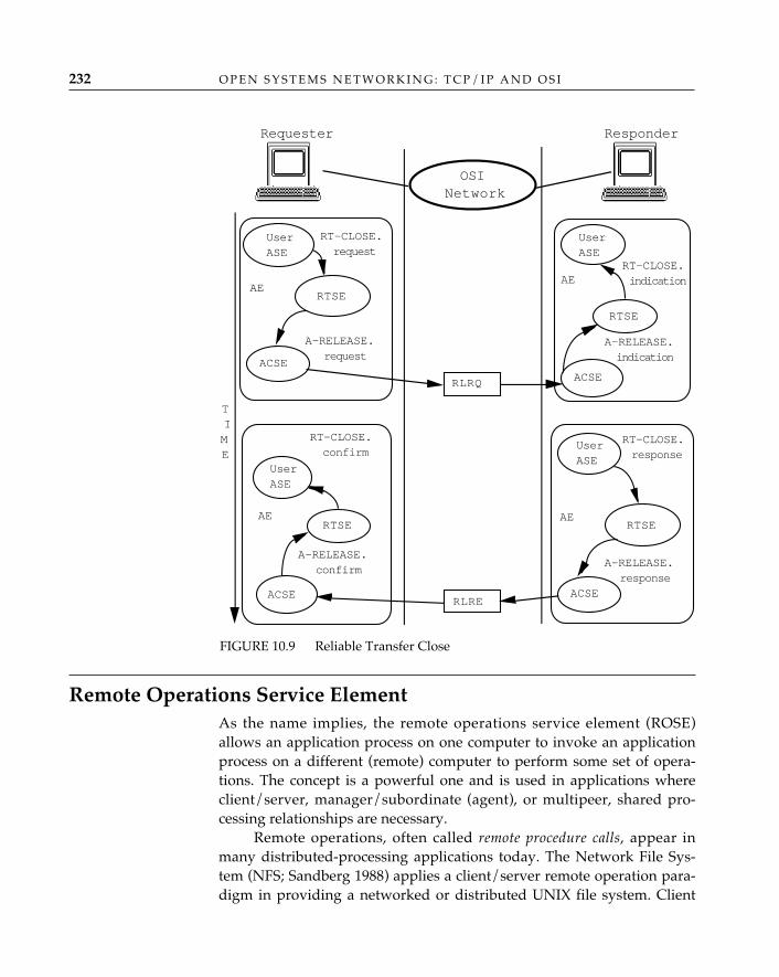
O P E N S Y S T E M S N E T W O R K I N G : T C P / I P A N D O S I232
Remote Operations Service Element As the name implies, the remote operations service element (ROSE)allows an application process on one computer to invoke an applicationprocess on a different (remote) computer to perform some set of opera-tions. The concept is a powerful one and is used in applications whereclient/server, manager/subordinate (agent), or multipeer, shared pro-cessing relationships are necessary.
Remote operations, often called remote procedure calls, appear inmany distributed-processing applications today. The Network File Sys-tem (NFS; Sandberg 1988) applies a client/server remote operation para-digm in providing a networked or distributed UNIX file system. Client
FIGURE 10.9 Reliable Transfer Close
A-RELEASE.request
ACSE
RT-CLOSE.request
RTSE
ResponderRequester
OSINetwork
UserASE
AE
RLRQ
A-RELEASE.indication
ACSE
RT-CLOSE.indication
RTSE
UserASE
AE
TIME
A-RELEASE.response
ACSE
RT-CLOSE.response
RTSE
UserASE
AE
RLRE
A-RELEASE.confirm
ACSE
RT-CLOSE.confirm
RTSE
UserASE
AE
“ C O R E ” A P P L I C A T I O N S E R V I C E E L E M E N T S 233
workstations (often diskless) invoke the services of a “disk-full” computer,called a file server, to read information from, and write information to,long-term storage. Network management applications based on OSIcommon management use remote operations to invoke the services ofsubordinate or agent applications that run on manageable network re-sources to isolate and correct faults, configure those resources, and col-lect management information through some set of management opera-tions. And both the OSI Message Handling System and the OSI Directory(see Chapters 7 and 8) make extensive use of remote operations in thesomewhat similar user agent/transfer agent relationships.
Some distributed operating system applications—e.g., DUNE (Al-beri and Pucci 1987), LOCUS (Walker et al. 1983)—apply the client/server paradigm to a group of networked computers, whereas other dis-tributed operating systems behave as if they were a single “monster”multiprocessor, multitasking (super)computer, with each computer pos-sessing the ability to pass off a task or procedure to another, less busycomputer and each having “equal access” to the others’ resources (CPU,disk, etc.).
Just as the reliable transfer service element simplifies the process ofreliable data transfer between computer systems, the remote operationsservice element simplifies the process of distributing operations acrossmultiple computer systems. Like RTSE, ROSE relieves user elementsfrom having to worry about the details of association establishment andrelease (it either invokes association control itself or allows the reliabletransfer service element to do so) and bundles several layers of servicefeatures into a single service. Within the context of an association, ROSEallows an application process on a local computer to invoke an applica-tion process on a remote computer and request that it perform an opera-tion. The operations themselves are treated as ASE services and aredefined as abstract syntaxes in standard application service elements likethe MHS and Directory ASEs or in user-programmed application serviceelements. (Remote operations in OSI thus operate on abstract rather thanconcrete data types.) OSI collectively labels the set of ASE services avail-able to a user element of an application entity an operations interface(Figure 10.10).
In the figure, each “user ASE” represents some remote operation(s)the user element may invoke. The user element may use the ACSEdirectly to establish associations between itself and other user elements.The user element may optionally use the reliable transfer service elementto handle association control and reliable transfer if information transferbetween user elements would benefit from this additional facility.
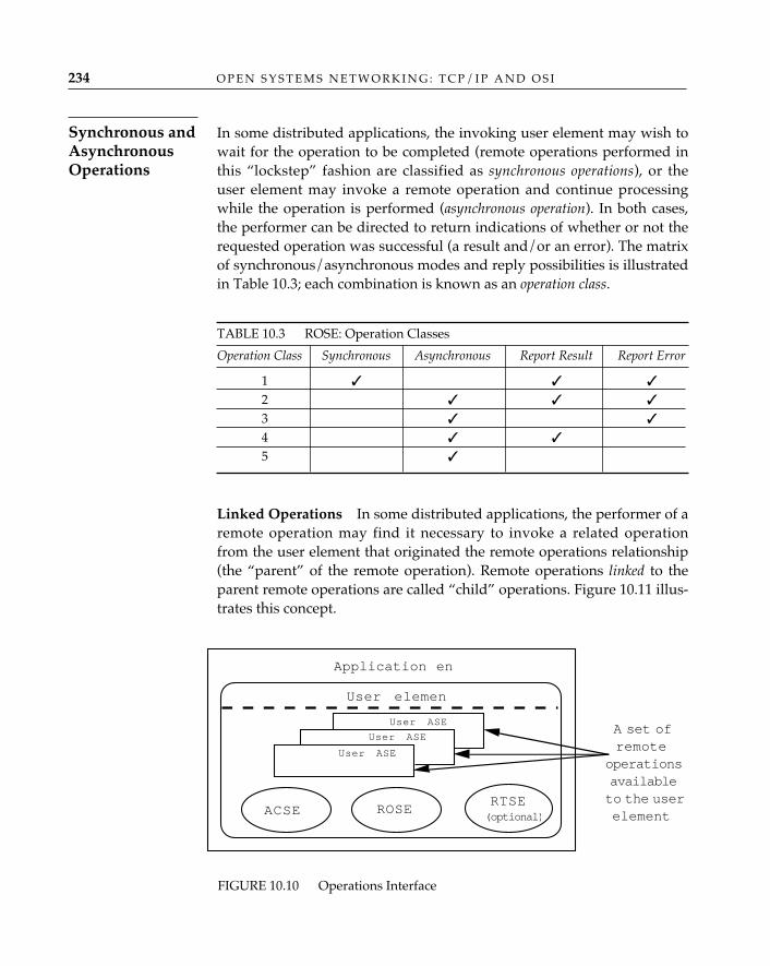
In some distributed applications, the invoking user element may wish towait for the operation to be completed (remote operations performed inthis “lockstep” fashion are classified as synchronous operations), or theuser element may invoke a remote operation and continue processingwhile the operation is performed (asynchronous operation). In both cases,the performer can be directed to return indications of whether or not therequested operation was successful (a result and/or an error). The matrixof synchronous/asynchronous modes and reply possibilities is illustratedin Table 10.3; each combination is known as an operation class.
TABLE 10.3 ROSE: Operation Classes
Operation Class Synchronous Asynchronous Report Result Report Error
1 ✓ ✓ ✓
2 ✓ ✓ ✓
3 ✓ ✓
4 ✓ ✓
5 ✓
Linked Operations—In some distributed applications, the performer of aremote operation may find it necessary to invoke a related operationfrom the user element that originated the remote operations relationship(the “parent” of the remote operation). Remote operations linked to theparent remote operations are called “child” operations. Figure 10.11 illus-trates this concept.
O P E N S Y S T E M S N E T W O R K I N G : T C P / I P A N D O S I234
Synchronous andAsynchronousOperations
FIGURE 10.10 Operations Interface
Application ent
ACSE ROSERTSE(optional)
User ASEA set ofremote
operationsavailableto the userelement
User elemen
User ASE
User ASE
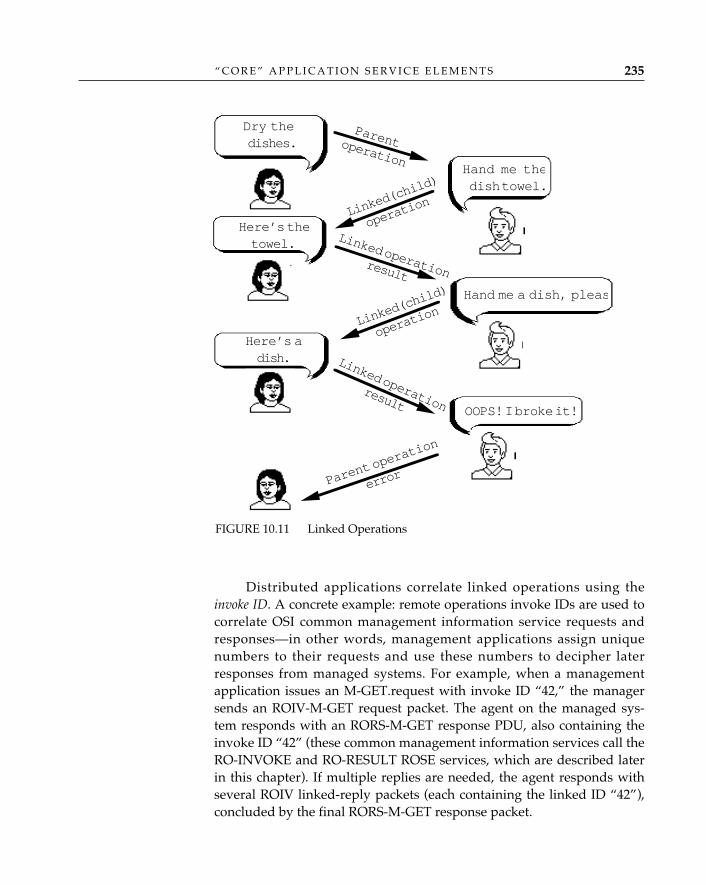
Distributed applications correlate linked operations using theinvoke ID. A concrete example: remote operations invoke IDs are used tocorrelate OSI common management information service requests andresponses—in other words, management applications assign uniquenumbers to their requests and use these numbers to decipher laterresponses from managed systems. For example, when a managementapplication issues an M-GET.request with invoke ID “42,” the managersends an ROIV-M-GET request packet. The agent on the managed sys-tem responds with an RORS-M-GET response PDU, also containing theinvoke ID “42” (these common management information services call theRO-INVOKE and RO-RESULT ROSE services, which are described laterin this chapter). If multiple replies are needed, the agent responds withseveral ROIV linked-reply packets (each containing the linked ID “42”),concluded by the final RORS-M-GET response packet.
“ C O R E ” A P P L I C A T I O N S E R V I C E E L E M E N T S 235
FIGURE 10.11 Linked Operations
Dry thedishes.
Hand me thedish towel.
Hand me a dish, pleas
OOPS! I broke it!
Parentoperation
Linked
(child
)
operat
ion
Linked operationresult
Parent
operat
ion
error
Linked
(child
)
operat
ion
Linked operationresult
Here’s thetowel.
Here’s adish.
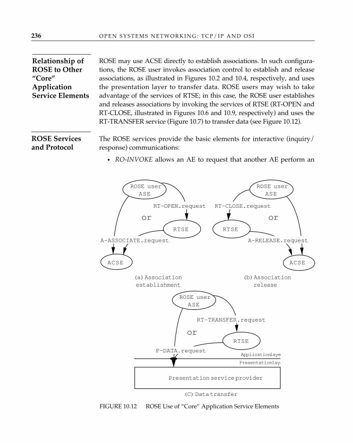
O P E N S Y S T E M S N E T W O R K I N G : T C P / I P A N D O S I236
ROSE may use ACSE directly to establish associations. In such configura-tions, the ROSE user invokes association control to establish and releaseassociations, as illustrated in Figures 10.2 and 10.4, respectively, and usesthe presentation layer to transfer data. ROSE users may wish to takeadvantage of the services of RTSE; in this case, the ROSE user establishesand releases associations by invoking the services of RTSE (RT-OPEN andRT-CLOSE, illustrated in Figures 10.6 and 10.9, respectively) and uses theRT-TRANSFER service (Figure 10.7) to transfer data (see Figure 10.12).
The ROSE services provide the basic elements for interactive (inquiry/response) communications:
• RO-INVOKE allows an AE to request that another AE perform an
ROSE Servicesand Protocol
Relationship ofROSE to Other“Core”ApplicationService Elements
FIGURE 10.12 ROSE Use of “Core” Application Service Elements
ROSE userASE
RT-OPEN.request
or
ACSE
RTSE
A-ASSOCIATE.request
ROSE userASE
RT-CLOSE.request
or
ACSE
RTSE
A-RELEASE.request
(a) Associationestablishment
(b) Associationrelease
ROSE userASE
RT-TRANSFER.request
or
Presentation service provider
RTSE
P-DATA.requestApplication layer
Presentation laye
(C) Data transfer
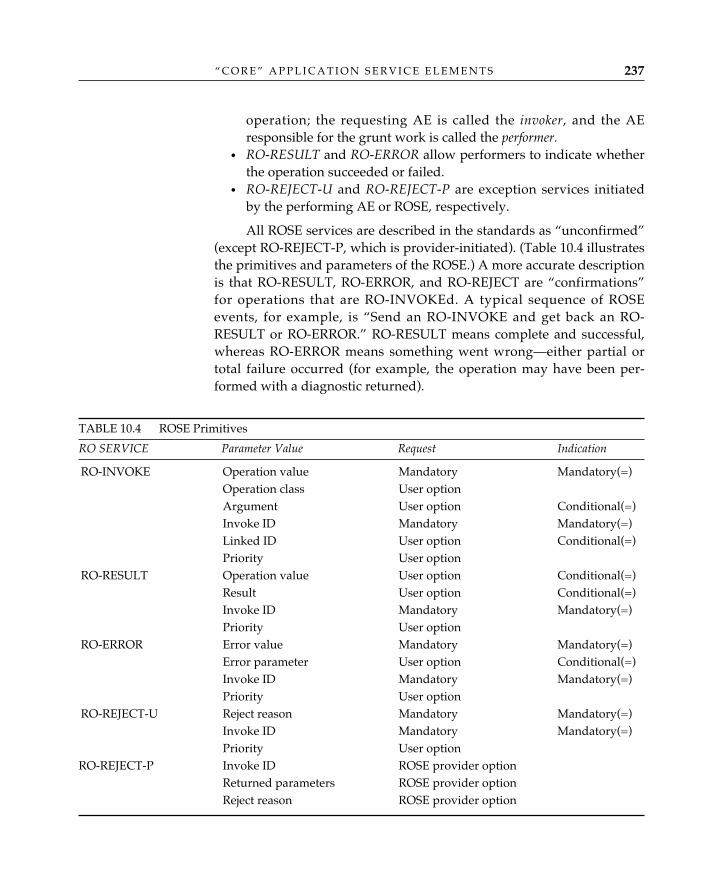
“ C O R E ” A P P L I C A T I O N S E R V I C E E L E M E N T S 237
operation; the requesting AE is called the invoker, and the AEresponsible for the grunt work is called the performer.
• RO-RESULT and RO-ERROR allow performers to indicate whetherthe operation succeeded or failed.
• RO-REJECT-U and RO-REJECT-P are exception services initiatedby the performing AE or ROSE, respectively.
All ROSE services are described in the standards as “unconfirmed”(except RO-REJECT-P, which is provider-initiated). (Table 10.4 illustratesthe primitives and parameters of the ROSE.) A more accurate descriptionis that RO-RESULT, RO-ERROR, and RO-REJECT are “confirmations”for operations that are RO-INVOKEd. A typical sequence of ROSEevents, for example, is “Send an RO-INVOKE and get back an RO-RESULT or RO-ERROR.” RO-RESULT means complete and successful,whereas RO-ERROR means something went wrong—either partial ortotal failure occurred (for example, the operation may have been per-formed with a diagnostic returned).
TABLE 10.4 ROSE Primitives
RO SERVICE Parameter Value Request Indication
RO-INVOKE Operation value Mandatory Mandatory(=)Operation class User optionArgument User option Conditional(=)Invoke ID Mandatory Mandatory(=)Linked ID User option Conditional(=)Priority User option
RO-RESULT Operation value User option Conditional(=)Result User option Conditional(=)Invoke ID Mandatory Mandatory(=)Priority User option
RO-ERROR Error value Mandatory Mandatory(=)Error parameter User option Conditional(=)Invoke ID Mandatory Mandatory(=)Priority User option
RO-REJECT-U Reject reason Mandatory Mandatory(=)Invoke ID Mandatory Mandatory(=)Priority User option
RO-REJECT-P Invoke ID ROSE provider optionReturned parameters ROSE provider optionReject reason ROSE provider option
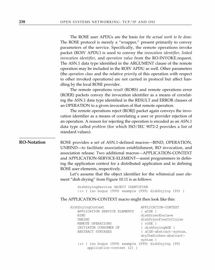
O P E N S Y S T E M S N E T W O R K I N G : T C P / I P A N D O S I238
The ROSE user APDUs are the basis for the actual work to be done.The ROSE protocol is merely a “wrapper,” present primarily to conveyparameters of the service. Specifically, the remote operations invokepacket (ROIV APDU) is used to convey the invocation identifier, linkedinvocation identifier, and operation value from the RO-INVOKE.request.The ASN.1 data type identified in the ARGUMENT clause of the remoteoperation may be included in the ROIV APDU as well. Other parameters(the operation class and the relative priority of this operation with respectto other invoked operations) are not carried in protocol but affect han-dling by the local ROSE provider.
The remote operations result (RORS) and remote operations error(ROER) packets convey the invocation identifier as a means of correlat-ing the ASN.1 data type identified in the RESULT and ERROR clauses ofan OPERATION to a given invocation of that remote operation.
The remote operations reject (RORJ) packet again conveys the invo-cation identifier as a means of correlating a user or provider rejection ofan operation. A reason for rejecting the operation is encoded as an ASN.1data type called problem (for which ISO/IEC 9072-2 provides a list ofstandard values).
ROSE provides a set of ASN.1-defined macros—BIND, OPERATION,UNBIND—to facilitate association establishment, RO invocation, andassociation release. Two additional macros—APPLICATION-CONTEXTand APPLICATION-SERVICE-ELEMENT—assist programmers in defin-ing the application context for a distributed application and in definingROSE user elements, respectively.
Let’s assume that the object identifier for the whimsical user ele-ment “dish drying” from Figure 10.11 is as follows:
dishDryingService OBJECT IDENTIFIER::= { iso bogus (999) example (999) dishDrying (99) }
The APPLICATION-CONTEXT macro might then look like this:
dishDryingContext APPLICATION-CONTEXTAPPLICATION SERVICE ELEMENTS { aCSE }BIND dishDryerEnslaveUNBIND dishDryerFreeToCruiseREMOTE OPERATIONS { rOSE }INITIATOR CONSUMER OF { dishDryingASE }ABSTRACT SYNTAXES { aCSE-abstract-syntax,
dryTheDishes-abstract-syntax }
::= { iso bogus (999) example (999) dishDrying (99)application-context (2) }
RO-Notation
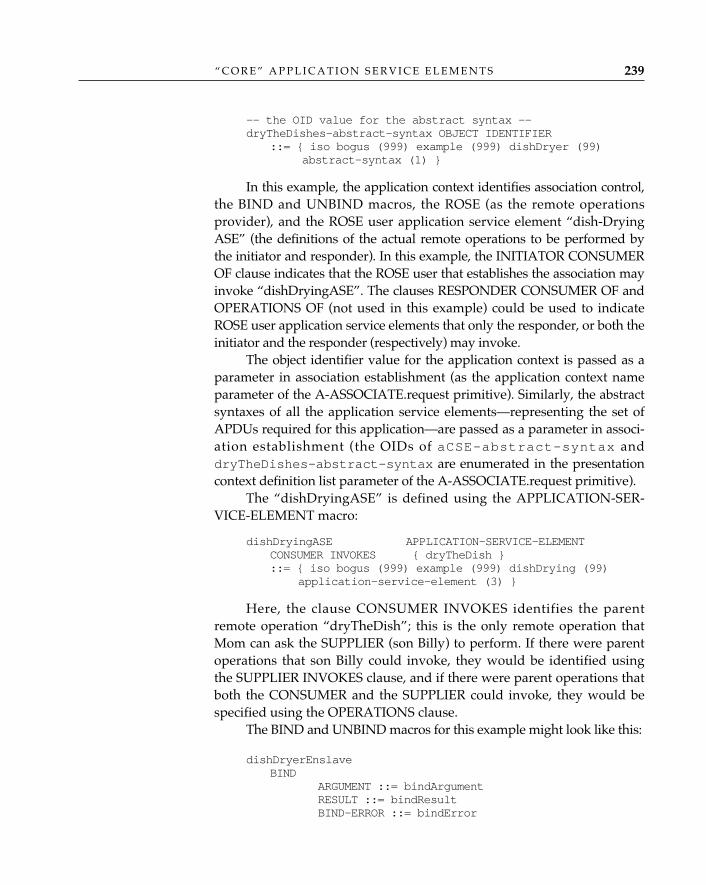
“ C O R E ” A P P L I C A T I O N S E R V I C E E L E M E N T S 239
-- the OID value for the abstract syntax --dryTheDishes-abstract-syntax OBJECT IDENTIFIER
::= { iso bogus (999) example (999) dishDryer (99) abstract-syntax (1) }
In this example, the application context identifies association control,the BIND and UNBIND macros, the ROSE (as the remote operationsprovider), and the ROSE user application service element “dish-DryingASE” (the definitions of the actual remote operations to be performed bythe initiator and responder). In this example, the INITIATOR CONSUMEROF clause indicates that the ROSE user that establishes the association mayinvoke “dishDryingASE”. The clauses RESPONDER CONSUMER OF andOPERATIONS OF (not used in this example) could be used to indicateROSE user application service elements that only the responder, or both theinitiator and the responder (respectively) may invoke.
The object identifier value for the application context is passed as aparameter in association establishment (as the application context nameparameter of the A-ASSOCIATE.request primitive). Similarly, the abstractsyntaxes of all the application service elements—representing the set ofAPDUs required for this application—are passed as a parameter in associ-ation establishment (the OIDs of aCSE-abstract-syntax anddryTheDishes-abstract-syntax are enumerated in the presentationcontext definition list parameter of the A-ASSOCIATE.request primitive).
The “dishDryingASE” is defined using the APPLICATION-SER-VICE-ELEMENT macro:
dishDryingASE APPLICATION-SERVICE-ELEMENTCONSUMER INVOKES { dryTheDish }::= { iso bogus (999) example (999) dishDrying (99)
application-service-element (3) }
Here, the clause CONSUMER INVOKES identifies the parentremote operation “dryTheDish”; this is the only remote operation thatMom can ask the SUPPLIER (son Billy) to perform. If there were parentoperations that son Billy could invoke, they would be identified usingthe SUPPLIER INVOKES clause, and if there were parent operations thatboth the CONSUMER and the SUPPLIER could invoke, they would bespecified using the OPERATIONS clause.
The BIND and UNBIND macros for this example might look like this:
dishDryerEnslaveBIND
ARGUMENT ::= bindArgumentRESULT ::= bindResultBIND-ERROR ::= bindError
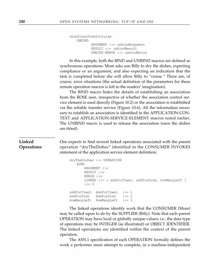
O P E N S Y S T E M S N E T W O R K I N G : T C P / I P A N D O S I240
dishDryerFreeToCruiseUNBIND
ARGUMENT ::= unbindArgumentRESULT ::= unbindResultUNBIND-ERROR ::= unbindError
In this example, both the BIND and UNBIND macros are defined assynchronous operations: Mom asks son Billy to dry the dishes, expectingcompliance or an argument, and also expecting an indication that thetask is completed before she will allow Billy to “cruise.” There are, ofcourse, error situations (the actual definition of the parameters for theseremote operation macros is left to the readers’ imagination).
The BIND macro hides the details of establishing an associationfrom the ROSE user, irrespective of whether the association control ser-vice element is used directly (Figure 10.2) or the association is establishedvia the reliable transfer service (Figure 10.6). All the information neces-sary to establish an association is identified in the APPLICATION-CON-TEXT and APPLICATION-SERVICE-ELEMENT macros noted earlier.The UNBIND macro is used to release the association (once the dishesare dried).
One expects to find several linked operations associated with the parentoperation “dryTheDishes” identified in the CONSUMER INVOKESstatement of the application service element definition:
dryTheDishes ::= OPERATIONBIND
ARGUMENT ::= RESULT ::= ERROR ::= LINKED ::= { askForTowel, askForDish, howManyLeft }::= 0
askForTowel AskForTowel ::= 1askForDish AskForDish ::= 2howManyLeft HowManyLeft ::= 3
The linked operations identify work that the CONSUMER (Mom)may be called upon to do by the SUPPLIER (Billy). Note that each parentOPERATION may have local or globally unique values; i.e., the data typeof operations may be INTEGER (as illustrated) or OBJECT IDENTIFIER.The linked operations are identified within the context of the parentoperation.
The ASN.1 specification of each OPERATION formally defines thework a performer must attempt to complete, in a machine-independent
LinkedOperations
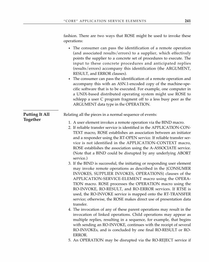
“ C O R E ” A P P L I C A T I O N S E R V I C E E L E M E N T S 241
fashion. There are two ways that ROSE might be used to invoke theseoperations:
• The consumer can pass the identification of a remote operation(and associated results/errors) to a supplier, which effectivelypoints the supplier to a concrete set of procedures to execute. Theinput to these concrete procedures and anticipated replies(results/errors) accompany this identification (the ARGUMENT,RESULT, and ERROR clauses).
• The consumer can pass the identification of a remote operation andaccompany this with an ASN.1-encoded copy of the machine-spe-cific software that is to be executed. For example, one computer ina UNIX-based distributed operating system might use ROSE toschlepp a user C program fragment off to a less busy peer as theARGUMENT data type in the OPERATION.
Relating all the pieces in a normal sequence of events:
1. A user element invokes a remote operation via the BIND macro. 2. If reliable transfer service is identified in the APPLICATION-CON-
TEXT macro, ROSE establishes an association between an initiatorand a responder using the RT-OPEN service. If reliable transfer ser-vice is not identified in the APPLICATION-CONTEXT macro,ROSE establishes the association using the A-ASSOCIATE service.(Note that a BIND could be disrupted by any underlying ABORTservice.)
3. If the BIND is successful, the initiating or responding user elementmay invoke remote operations as described in the {CONSUMERINVOKES, SUPPLIER INVOKES, OPERATIONS} clauses of theAPPLICATION-SERVICE-ELEMENT macro using the OPERA-TION macro. ROSE processes the OPERATION macro using theRO-INVOKE, RO-RESULT, and RO-ERROR services. If RTSE isused, the RO-INVOKE service is mapped onto the RT-TRANSFERservice; otherwise, the ROSE makes direct use of presentation datatransfer.
4. The invocation of any of these parent operations may result in theinvocation of linked operations. Child operations may appear asmultiple replies, resulting in a sequence, for example, that beginswith sending an RO-INVOKE, continues with the receipt of severalRO-INVOKEs, and is concluded by one final RO-RESULT or RO-ERROR.
5. An OPERATION may be disrupted via the RO-REJECT service if
Putting It AllTogether
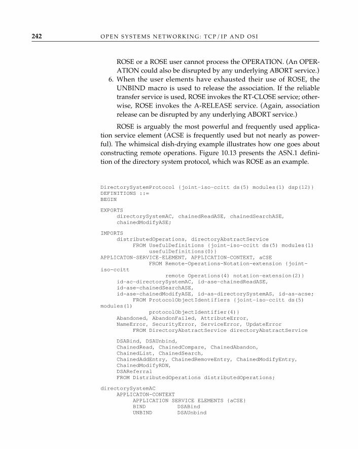
O P E N S Y S T E M S N E T W O R K I N G : T C P / I P A N D O S I242
ROSE or a ROSE user cannot process the OPERATION. (An OPER-ATION could also be disrupted by any underlying ABORT service.)
6. When the user elements have exhausted their use of ROSE, theUNBIND macro is used to release the association. If the reliabletransfer service is used, ROSE invokes the RT-CLOSE service; other-wise, ROSE invokes the A-RELEASE service. (Again, associationrelease can be disrupted by any underlying ABORT service.)
ROSE is arguably the most powerful and frequently used applica-tion service element (ACSE is frequently used but not nearly as power-ful). The whimsical dish-drying example illustrates how one goes aboutconstructing remote operations. Figure 10.13 presents the ASN.1 defini-tion of the directory system protocol, which was ROSE as an example.
DirectorySystemProtocol {joint-iso-ccitt ds(5) modules(1) dsp(12)}DEFINITIONS ::=BEGIN
EXPORTSdirectorySystemAC, chainedReadASE, chainedSearchASE,chainedModifyASE;
IMPORTSdistributedOperations, directoryAbstractService
FROM UsefulDefinitions {joint-iso-ccitt ds(5) modules(1)usefulDefinitions(0)}
APPLICATON-SERVICE-ELEMENT, APPLICATION-CONTEXT, aCSEFROM Remote-Operations-Notation-extension {joint-
iso-ccitt remote Operations(4) notation-extension(2)}
id-ac-directorySystemAC, id-ase-chainedReadASE,id-ase-chainedSearchASE,id-ase-chainedModifyASE, id-as-directorySystemAS, id-as-acse;
FROM ProtocolObjectIdentifiers {joint-iso-ccitt ds(5)modules(1)
protocolObjectIdentifier(4)}Abandoned, AbandonFailed, AttributeError,NameError, SecurityError, ServiceError, UpdateError
FROM DirectoryAbstractService directoryAbstractService
DSABind, DSAUnbind,ChainedRead, ChainedCompare, ChainedAbandon,ChainedList, ChainedSearch,ChainedAddEntry, ChainedRemoveEntry, ChainedModifyEntry,ChainedModifyRDN,DSAReferralFROM DistributedOperations distributedOperations;
directorySystemACAPPLICATON-CONTEXT
APPLICATION SERVICE ELEMENTS {aCSE}BIND DSABindUNBIND DSAUnbind
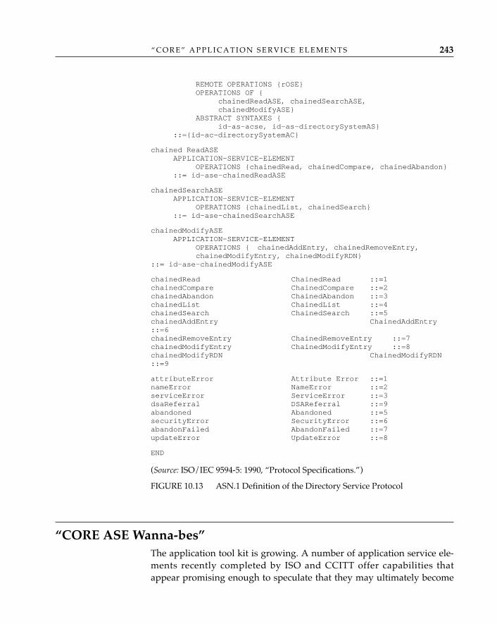
“ C O R E ” A P P L I C A T I O N S E R V I C E E L E M E N T S 243
REMOTE OPERATIONS {rOSE}OPERATIONS OF {
chainedReadASE, chainedSearchASE,chainedModifyASE}
ABSTRACT SYNTAXES {id-as-acse, id-as-directorySystemAS}
::={id-ac-directorySystemAC}
chained ReadASEAPPLICATION-SERVICE-ELEMENT
OPERATIONS {chainedRead, chainedCompare, chainedAbandon}::= id-ase-chainedReadASE
chainedSearchASEAPPLICATION-SERVICE-ELEMENT
OPERATIONS {chainedList, chainedSearch}::= id-ase-chainedSearchASE
chainedModifyASEAPPLICATION-SERVICE-ELEMENT
OPERATIONS { chainedAddEntry, chainedRemoveEntry,chainedModifyEntry, chainedModifyRDN}
::= id-ase-chainedModifyASE
chainedRead ChainedRead ::=1chainedCompare ChainedCompare ::=2chainedAbandon ChainedAbandon ::=3chainedList ChainedList ::=4chainedSearch ChainedSearch ::=5chainedAddEntry ChainedAddEntry::=6chainedRemoveEntry ChainedRemoveEntry ::=7chainedModifyEntry ChainedModifyEntry ::=8chainedModifyRDN ChainedModifyRDN::=9
attributeError Attribute Error ::=1nameError NameError ::=2serviceError ServiceError ::=3dsaReferral DSAReferral ::=9abandoned Abandoned ::=5securityError SecurityError ::=6abandonFailed AbandonFailed ::=7updateError UpdateError ::=8
END
(Source: ISO/IEC 9594-5: 1990, “Protocol Specifications.”)
FIGURE 10.13 ASN.1 Definition of the Directory Service Protocol
“CORE ASE Wanna-bes”The application tool kit is growing. A number of application service ele-ments recently completed by ISO and CCITT offer capabilities thatappear promising enough to speculate that they may ultimately become
O P E N S Y S T E M S N E T W O R K I N G : T C P / I P A N D O S I244
members of the “core.” Although it is beyond the scope of this book toaddress every application service element, there is a growing number ofapplication service elements that one might classify as “core ASE wanna-bes.” In the area of transaction processing, for example, there are threecandidates. The OSI commitment, concurrency, and recovery (ISO/IEC 9804:1990; ISO/IEC 9805: 1990), distributed transaction processing (ISO/IEC DIS10026: 1992), and remote database access (ISO/IEC DIS 9579: 1992) servicesprovide ways to associate a sequence of operations (a transaction or anatomic action) performed on remotely accessed data, such that either theentire sequence of operations must be performed on the data or theeffects of all the operations must be undone. This “all or none” character-istic is referred to as atomicity. Assuring that the effects of the operationsleave the data in either the original or the revised state (but no other) iscalled consistency. Another characteristic of processing a transaction isdata isolation: from the time a transaction is initiated until it is completed,all data involved in the transaction may not be accessed by any othertransaction.
A final characteristic of transaction processing is that once the dataare changed, the changes endure failures of any subsequent transactionperformed on the data. For example, if a transaction “foo” succeeds andresults in a counter’s value being changed from 1 to 2, the subsequentfailure of a transaction “bar” cannot “undo” the effect of “foo” by leavingthe counter with a value other than 2.
Commitment concurrency and recovery, transaction processing,and remote database access service elements are enabling vehicles fordistributed-processing applications such as electronic banking (automat-ed teller machines), point-of-sale inventory control, purchasing usingdebit cards, electronic brokering, and remote database access.
Early in the development of the OSI application layer, the termscommon application service elements (CASE) and specific application serviceelements (SASE) were abandoned because no consensus could be reachedon what criteria should be used to distinguish what was common fromwhat was specific. This problem exists only if you persist in believingthat the classification of an application service element is something stat-ic rather than dynamic. The true measure of whether an application ser-vice element is among the “core” set of application tools is how exten-sively it is used. Although the OSI Message Handling System and theDirectory may be considered specific end-user applications today, in thefuture—as standards for office document management, banking, elec-tronic data interchange, document filing and retrieval, and electroniclibrary applications emerge—these, too, may become “core ASEs.”
“ C O R E ” A P P L I C A T I O N S E R V I C E E L E M E N T S 245
ConclusionThis chapter concludes the discussion of the application layer. It hasexamined the most frequently used application service elements—ACSE,RTSE, and ROSE—and illustrated how these ASEs provide services, indi-vidually and collectively, to the application service elements described inChapters 7, 8, and 9. In the process, the authors have attempted todemonstrate the modularity of the OSI application layer and the flexibili-ty afforded a user element (a specific application service) when a set ofgeneral-purpose mechanisms are made available to a developer of dis-tributed application services.
The presentation and session layers collaborate to provide many of thedistributed-processing capabilities presented to user elements by the ser-vice elements of the application layer; for this reason, they are discussedtogether.
Presentation LayerChapter 4 describes how ASN.1 provides the application programmerwith a tool for creating data structures that are syntactically independentfrom the way in which data are stored in a computer and from the wayin which they are transferred between computer systems. Transformingthese abstract syntaxes into “concrete” data structures appropriate for agiven operating system (e.g., UNIX, DOS, VMS, MVS) is typically han-dled by tools such as ASN.1 compilers. The task of preserving the seman-tics of the data exchanged between a sender and receiver across an OSInetwork is handled by the presentation layer, which performs the trans-formations from the local (concrete) syntax used by each application entityto a common transfer syntax. This leads us to the discussion of the notionof a presentation context set.
The presentation layer is responsible for managing the transfer syntaxesassociated with the set of abstract syntaxes that will be used by applica-tion entities as they exchange information across a presentation connec-tion. As part of presentation connection establishment, application enti-ties must be sure that the presentation layer can support a transfer syntax
11 THE PRESENTATION AND SESSION LAYERS
247
Context SetDefinition
O P E N S Y S T E M S N E T W O R K I N G : T C P / I P A N D O S I248
for every abstract syntax required by the distributed-processing applica-tion(s) that will use this connection. A presentation context definition list,consisting of a presentation context identifier and an abstract syntaxname, is created by the application entity that initiates the presentationconnection establishment. The responding application entity determineswhether the list is complete and whether it can be supported, on a “per-entry” basis. The set of presentation contexts resulting from this negotia-tion is called the defined context set (DCS).1
The presentation service (ISO/IEC 8882: 1988) is presented in terms ofthe facilities it provides. The connection establishment (P-CONNECT) andconnection termination facilities (P-RELEASE, P-U-ABORT, P-P-ABORT)provide presentation connection management between communicatingapplication entities. Within the context established for a presentationconnection, and through the use of the context management facility (P-ALTER-CONTEXT), the presentation layer preserves the semantics ofdata as they are transferred between applications.
In OSI, certain functions reflected by application service elementsare performed in the session layer—e.g., token management, synchro-nization, and checkpointing. When these session layer services areinvoked, and because the rigid layering prescribed by the OSI referencemodel does not allow one to “skip layers,” the presentation layer is seem-ingly “in the way.” The presentation layer does not provide the servicedirectly but instead passes these service primitives between the applica-tion and session layers; thus, the so-called pass-throughs were born. Forapplications that require direct manipulation of session services, the pre-sentation layer offers applications “pass-through” facilities to servicesoffered by the session layer. Collectively identified under the rubric dia-logue control, they consist of 21 services that directly reflect session layertoken management, activity management, data synchronization, andexception reporting services.
(The complete set of primitives and parameters of the presentationservice is illustrated in Table 11.1.)
Note that although the presentation layer service primitives suggestthat the presentation layer has some active role in providing activity andtoken management, synchronization, and exception services, this is not
PresentationService
1. A default context is always known by the presentation service provider and the ser-vice users. The need for a default context arises (once again) from the need to support theX.410-1984 mode of the OSI Message Handling System; when no presentation protocol isexchanged, the default context is assumed. The default context name may also be passed as aparameter during presentation connection establishment.
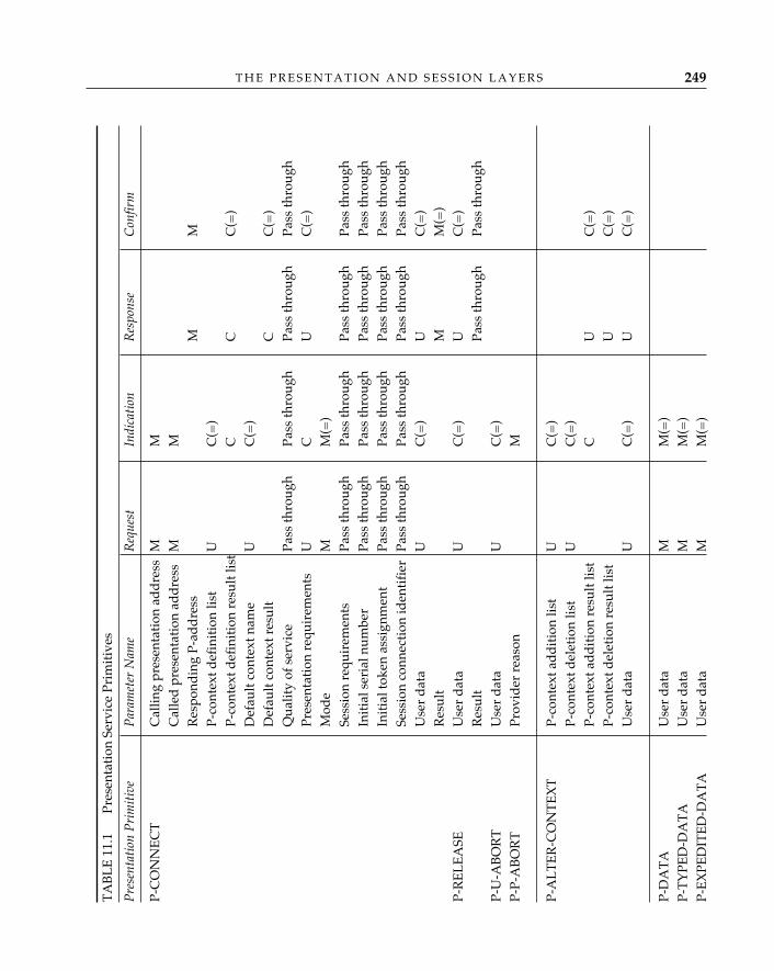
T H E P R E S E N T A T I O N A N D S E S S I O N L A Y E R S 249
TA
BL
E 1
1.1
P
rese
ntat
ion
Serv
ice
Prim
itiv
es
Pre
sent
atio
n P
rim
itiv
eP
aram
eter
Nam
eR
eque
stIn
dica
tion
Res
pons
eC
onfir
m
P-C
ON
NE
CT
Cal
ling
pres
enta
tion
ad
dre
ssM
MC
alle
d p
rese
ntat
ion
add
ress
MM
Res
pond
ing
P-ad
dre
ssM
MP-
cont
ext d
efin
itio
n lis
tU
C(=
)P-
cont
ext d
efin
itio
n re
sult
list
CC
C(=
)D
efau
lt c
onte
xt n
ame
UC
(=)
Def
ault
con
text
res
ult
CC
(=)
Qua
lity
of s
ervi
cePa
ss th
roug
hPa
ss th
roug
hPa
ss th
roug
hPa
ss th
roug
hPr
esen
tati
on r
equi
rem
ents
UC
UC
(=)
Mod
eM
M(=
)Se
ssio
n re
quir
emen
tsPa
ss th
roug
hPa
ss th
roug
hPa
ss th
roug
hPa
ss th
roug
hIn
itia
l ser
ial n
umbe
rPa
ss th
roug
hPa
ss th
roug
hPa
ss th
roug
hPa
ss th
roug
hIn
itia
l tok
en a
ssig
nmen
tPa
ss th
roug
hPa
ss th
roug
hPa
ss th
roug
hPa
ss th
roug
hSe
ssio
n co
nnec
tion
iden
tifi
erPa
ss th
roug
hPa
ss th
roug
hPa
ss th
roug
hPa
ss th
roug
hU
ser
dat
aU
C(=
)U
C(=
)R
esul
tM
M(=
)P-
RE
LE
ASE
Use
r d
ata
UC
(=)
UC
(=)
Res
ult
Pass
thro
ugh
Pass
thro
ugh
P-U
-AB
OR
TU
ser
dat
aU
C(=
)P-
P-A
BO
RT
Prov
ider
rea
son
M
P-A
LT
ER
-CO
NT
EX
TP-
cont
ext a
dd
itio
n lis
tU
C(=
)P-
cont
ext d
elet
ion
list
UC
(=)
P-co
ntex
t ad
dit
ion
resu
lt li
stC
UC
(=)
P-co
ntex
t del
etio
n re
sult
list
UC
(=)
Use
r d
ata
UC
(=)
UC
(=)
P-D
AT
AU
ser
dat
aM
M(=
)P-
TY
PED
-DA
TA
Use
r d
ata
MM
(=)
P-E
XPE
DIT
ED
-DA
TA
Use
r d
ata
MM
(=)
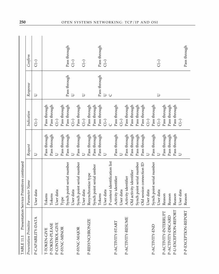
O P E N S Y S T E M S N E T W O R K I N G : T C P / I P A N D O S I250T
AB
LE
11.
1
Pre
sent
atio
n Se
rvic
e Pr
imit
ives
con
tinu
ed
Pre
sent
atio
n P
rim
itiv
eP
aram
eter
Nam
eR
eque
stIn
dica
tion
Res
pons
eC
onfir
m
P-C
APA
BIL
ITY
-DA
TA
Use
r d
ata
U
C(=
)U
C(=
)
T-T
OK
EN
-GIV
ET
oken
sPa
ss th
roug
hPa
ss th
roug
hP-
TO
KE
N-P
LE
ASE
Tok
ens
Pass
thro
ugh
Pass
thro
ugh
P-C
ON
TR
OL
-GIV
EU
ser
dat
aU
C(=
)P-
SYN
C-M
INO
RT
ype
Pass
thro
ugh
Pass
thro
ugh
Sync
h po
int s
eria
l num
ber
Pass
thro
ugh
Pass
thro
ugh
Pass
thro
ugh
Pass
thro
ugh
Use
r d
ata
U
C(=
) U
C(=
)P-
SYN
C-M
AJO
RSy
nch
poin
t ser
ial n
umbe
rPa
ss th
roug
hPa
ss th
roug
hU
ser
dat
aU
C(=
)U
C(=
)P-
RE
SYN
CH
RO
NIZ
ER
esyn
chro
nize
type
Pass
thro
ugh
Pass
thro
ugh
Sync
h po
int s
eria
l um
ber
Pass
thro
ugh
Pass
thro
ugh
Tok
ens
Pass
thro
ugh
Pass
thro
ugh
Pass
thro
ugh
Pass
thro
ugh
Use
r d
ata
UC
(=)
UC
(=)
P-co
ntex
t id
enti
fica
tion
list
CC
P-A
CT
IVIT
Y-S
TA
RT
Act
ivit
y id
enti
fier
Pass
thro
ugh
Pass
thro
ugh
Use
r d
ata
UC
(=)
P-A
CT
IVIT
Y-R
ESU
ME
Act
ivit
y id
enti
fier
Pass
thro
ugh
Pass
thro
ugh
Old
act
ivit
y id
enti
fier
Pass
thro
ugh
Pass
thro
ugh
Sync
h po
int s
eria
l num
ber
Pass
thro
ugh
Pass
thro
ugh
Old
ses
sion
con
nect
ion
IDPa
ss th
roug
hPa
ss th
roug
hU
ser
dat
aU
C(=
)P-
AC
TIV
ITY
-EN
DSy
nch
poin
t ser
ial n
umbe
rPa
ss th
roug
hPa
ss th
roug
hU
ser
dat
aU
C
(=)
UC
(=)
P-A
CT
IVIT
Y-I
NT
ER
RU
PTR
easo
nPa
ss th
roug
hPa
ss th
roug
hP-
AC
TIV
ITY
-DIS
CA
RD
Rea
son
Pass
thro
ugh
Pass
thro
ugh
P-U
-EX
CE
PTIO
N-R
EPO
RT
Rea
son
Pass
thro
ugh
Pass
thro
ugh
Use
r d
ata
UC
(=)
P-P-
EX
CE
PTIO
N-R
EPO
RT
Rea
son
Pass
thro
ugh
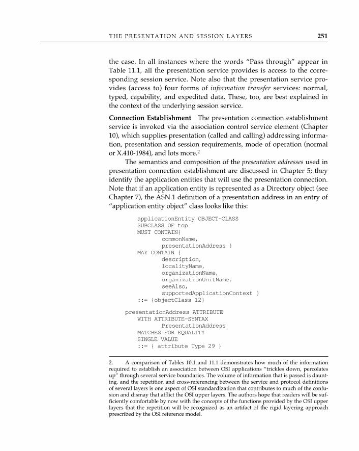
T H E P R E S E N T A T I O N A N D S E S S I O N L A Y E R S 251
the case. In all instances where the words “Pass through” appear inTable 11.1, all the presentation service provides is access to the corre-sponding session service. Note also that the presentation service pro-vides (access to) four forms of information transfer services: normal,typed, capability, and expedited data. These, too, are best explained inthe context of the underlying session service.
Connection Establishment—The presentation connection establishmentservice is invoked via the association control service element (Chapter10), which supplies presentation (called and calling) addressing informa-tion, presentation and session requirements, mode of operation (normalor X.410-1984), and lots more.2
The semantics and composition of the presentation addresses used inpresentation connection establishment are discussed in Chapter 5; theyidentify the application entities that will use the presentation connection.Note that if an application entity is represented as a Directory object (seeChapter 7), the ASN.1 definition of a presentation address in an entry of“application entity object” class looks like this:
applicationEntity OBJECT-CLASSSUBCLASS OF topMUST CONTAIN{
commonName, presentationAddress }
MAY CONTAIN {description, localityName,organizationName,organizationUnitName,seeAlso, supportedApplicationContext }
::= {objectClass 12}
presentationAddress ATTRIBUTEWITH ATTRIBUTE-SYNTAX
PresentationAddressMATCHES FOR EQUALITYSINGLE VALUE::= { attribute Type 29 }
2. A comparison of Tables 10.1 and 11.1 demonstrates how much of the informationrequired to establish an association between OSI applications “trickles down, percolatesup” through several service boundaries. The volume of information that is passed is daunt-ing, and the repetition and cross-referencing between the service and protocol definitionsof several layers is one aspect of OSI standardization that contributes to much of the confu-sion and dismay that afflict the OSI upper layers. The authors hope that readers will be suf-ficiently comfortable by now with the concepts of the functions provided by the OSI upperlayers that the repetition will be recognized as an artifact of the rigid layering approachprescribed by the OSI reference model.
O P E N S Y S T E M S N E T W O R K I N G : T C P / I P A N D O S I252
PresentationAddress ::= SEQUENCE {pSelector [0] OCTET STRING OPTIONAL,sSelector [1] OCTET STRING OPTIONAL,tSelector [2] OCTET STRING OPTIONAL,nAddresses [3] SET SIZE (1...MAX) OF OCTET STRING }
(Source: ISO/IEC 9594-6: 1990), “Selected Attribute Types.”
Presentation requirements are identified in terms of functional units, alogical grouping of services somehow distinct from facilities. There arethree presentation functional units:
• The kernel consists of connection establishment, release, abort, andnormal information transfer (P-DATA service only).
• The context management facility provides the ability to alter thedefined context set (to add or delete a presentation context).
• The context restoration facility, used in conjunction with the resyn-chronization service, allows the defined context set to be recordedat specified points during data transfer. If the presentation connec-tion is resurrected following a temporary failure, the DCS can berestored to one known at the specified “restart” point (i.e., to onethat both presentation users remember).
Session requirements, also identified in terms of functional units, rep-resent a checklist of the session services that will be used by the distrib-uted applications. They are provided in the P-CONNECT primitives (seeTable 11.1) so that they can be used in the negotiation of a session con-nection to support the distributed application.
The grouping of presentation services into both facilities andfunctional units is an artifact of the CCITT/ISO “mind-meld.”
CCITT speaks of services in terms of facilities, and initially, the presentation ser-vice was described in these terms. Later, when CCITT and ISO attempted tomerge several notions of the session layer into a single “service,” the term func-tional unit was introduced to better describe the relationship between seeminglydisjoint services. Although the presentation service is initially described in termsof facilities, the term is abandoned midway through ISO/IEC 8822 and neverused again.
In the normal mode of operation, these parameters are conveyed inthe connect presentation packet and the negotiated parameter values arereturned in the connect presentation accept packet (in Figure 11.1, the CPand CPA PPDUs, respectively). Recall from Chapter 10, however, that no
✧AHA✧
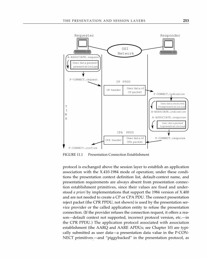
T H E P R E S E N T A T I O N A N D S E S S I O N L A Y E R S 253
protocol is exchanged above the session layer to establish an applicationassociation with the X.410-1984 mode of operation; under these condi-tions the presentation context definition list, default-context name, andpresentation requirements are always absent from presentation connec-tion establishment primitives, since their values are fixed and under-stood a priori by implementations that support the 1984 version of X.400and are not needed to create a CP or CPA PDU. The connect presentationreject packet (the CPR PPDU, not shown) is used by the presentation ser-vice provider or the called application entity to refuse the presentationconnection. (If the provider refuses the connection request, it offers a rea-son—default context not supported, incorrect protocol version, etc.—inthe CPR PPDU.) The application protocol associated with associationestablishment (the AARQ and AARE APDUs; see Chapter 10) are typi-cally submitted as user data—a presentation data value in the P-CON-NECT primitives,—and “piggybacked” in the presentation protocol, as
FIGURE 11.1 Presentation Connection Establishment
A-ASSOCIATE.request
A-ASSOCIATE.indication
A-ASSOCIATE.response
P-CONNECT.confirm
User data passed t
presentation laye
TIME
ResponderRequester
User data of
CP packet
P-CONNECT.request
CP header
User data receivedfrom presentation lay
P-CONNECT.indication
User data passedto presentation laye
P-CONNECT.responseUser data of
CPA packetCPA header
OSINetwork
CP PPDU
CPA PPDU
O P E N S Y S T E M S N E T W O R K I N G : T C P / I P A N D O S I254
illustrated in Figure 11.1.Many of the parameters used by association control during presen-
tation connection establishment are really intended for use in sessionconnection establishment. Among these are session requirements, sessionconnection identifier, initial assignment of tokens, and initial synch-pointserial number. These are used to negotiate a “proper” session connec-tion—one that ensures that all the tools required for communication arepresent. For example, if the reliable transfer service element is used by anapplication process, synchronization services and activity managementwould be included in the session requirements.
Release and Abort Services—The presentation layer provides applica-tion entities with access to the orderly (nondestructive) release serviceoffered by the session layer; parameters passed in the P-RELEASE ser-vice primitives (user data and result, see Table 11.1) are used in the corre-sponding session release service primitive. In the normal mode of opera-tion, the application protocol used to support the A-RELEASE service ispassed directly as user data to the S-RELEASE service; no explicit presen-tation protocol is used. (In Figure 11.2, the RLRQ and RLRE APDUs areconveyed as user data in the session finish packet, the FN SPDU.)
The abort service operates in much the same manner as the presen-tation release service. The application protocol used to support the A-ABORT service is conveyed as user data in P-U-ABORT primitives andsubsequently transferred in the abort release user packet (in Figure 11.3,the ARU PPDU). The presentation provider may also abort the presenta-tion connection if a protocol error is detected; here, the abort releaseprovider packet (the ARP PPDU, not shown) is sent by the presentationentity that detected the error. (This, of course, begs the question ofwhether the presentation entity that generated an erroneous packetremains capable of interpreting the ARP packet, but it does provide clo-sure.)
Context Set Negotiation—When a presentation connection is establishedfor a single application service element—the message transfer service ele-ment of the OSI Message-Handling System, for example—the negotiationprocess is a formality: all entries in the presentation-context definition listshould be supported. When an attempt is made to allow two or moreapplication service elements to share a single presentation connection,the situation becomes more complex. If, for example, the initiating userelement wants to allow both the Directory and the common managementinformation service to operate over a single presentation connection, butthe responder doesn’t support the directory service, the responder can
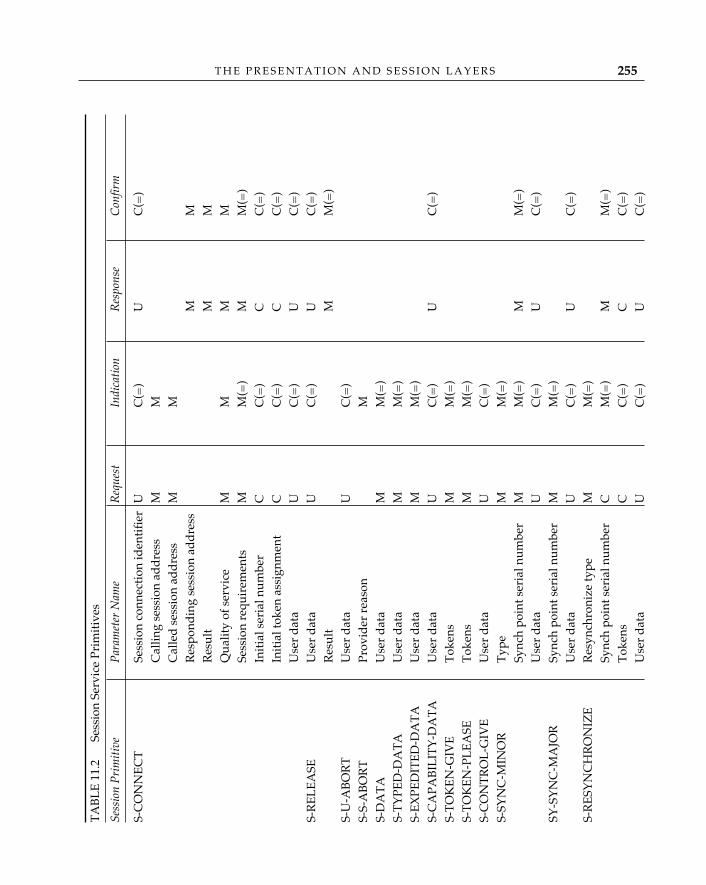
T H E P R E S E N T A T I O N A N D S E S S I O N L A Y E R S 255
TA
BL
E 1
1.2
S
essi
on S
ervi
ce P
rim
itiv
es
Sess
ion
Pri
mit
ive
Par
amet
er N
ame
Req
uest
Indi
cati
onR
espo
nse
Con
firm
S-C
ON
NE
CT
Sess
ion
conn
ecti
on id
enti
fier
UC
(=)
UC
(=)
Cal
ling
sess
ion
add
ress
MM
Cal
led
ses
sion
ad
dre
ssM
MR
espo
ndin
g se
ssio
n ad
dre
ssM
MR
esul
tM
MQ
ualit
y of
ser
vice
MM
MM
Sess
ion
requ
irem
ents
MM
(=)
MM
(=)
Init
ial s
eria
l num
ber
CC
(=)
CC
(=)
Init
ial t
oken
ass
ignm
ent
CC
(=)
CC
(=)
Use
r d
ata
UC
(=)
UC
(=)
S-R
EL
EA
SEU
ser
dat
aU
C(=
)U
C(=
)R
esul
tM
M(=
)S-
U-A
BO
RT
Use
r d
ata
UC
(=)
S-S-
AB
OR
TPr
ovid
er r
easo
nM
S-D
AT
AU
ser
dat
aM
M(=
)S-
TY
PED
-DA
TA
Use
r d
ata
MM
(=)
S-E
XPE
DIT
ED
-DA
TA
Use
r d
ata
MM
(=)
S-C
APA
BIL
ITY
-DA
TA
Use
r d
ata
UC
(=)
UC
(=)
S-T
OK
EN
-GIV
ET
oken
sM
M(=
)S-
TO
KE
N-P
LE
ASE
Tok
ens
MM
(=)
S-C
ON
TR
OL
-GIV
EU
ser
dat
aU
C(=
)S-
SYN
C-M
INO
RT
ype
MM
(=)
Sync
h po
int s
eria
l num
ber
MM
(=)
MM
(=)
Use
r d
ata
UC
(=)
UC
(=)
SY-S
YN
C-M
AJO
RSy
nch
poin
t ser
ial n
umbe
rM
M(=
)U
ser
dat
aU
C(=
)U
C(=
)S-
RE
SYN
CH
RO
NIZ
ER
esyn
chro
nize
type
MM
(=)
Sync
h po
int s
eria
l num
ber
CM
(=)
MM
(=)
Tok
ens
CC
(=)
CC
(=)
Use
r d
ata
UC
(=)
UC
(=)
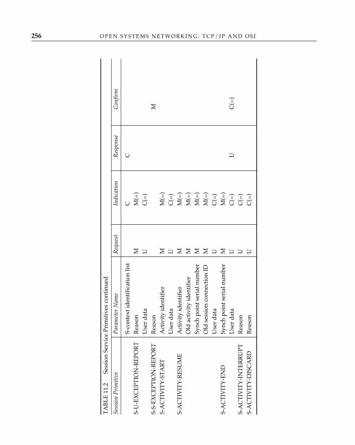
O P E N S Y S T E M S N E T W O R K I N G : T C P / I P A N D O S I256
TA
BL
E 1
1.2
S
essi
on S
ervi
ce P
rim
itiv
es c
onti
nued
Sess
ion
Pri
mit
ive
Par
amet
er N
ame
Req
uest
Indi
cati
onR
espo
nse
Con
firm
S-co
ntex
t id
enti
fica
tion
list
CC
S-U
-EX
CE
PTIO
N-R
EPO
RT
Rea
son
MM
(=)
Use
r d
ata
UC
(=)
S-S-
EX
CE
PTIO
N-R
EPO
RT
Rea
son
MS-
AC
TIV
ITY
-ST
AR
TA
ctiv
ity
iden
tifi
erM
M(=
)U
ser
dat
aU
C(=
)S-
AC
TIV
ITY
-RE
SUM
EA
ctiv
ity
iden
tifi
erM
M(=
)O
ld a
ctiv
ity
iden
tifi
erM
M(=
)Sy
nch
poin
t ser
ial n
umbe
rM
M(=
)O
ld s
essi
on c
onne
ctio
n ID
MM
(=)
Use
r d
ata
UC
(=)
S-A
CT
IVIT
Y-E
ND
Sync
h po
int s
eria
l num
ber
MM
(=)
Use
r d
ata
UC
(=)
UC
(=)
S-A
CT
IVIT
Y-I
NT
ER
RU
PTR
easo
nU
C(=
)S-
AC
TIV
ITY
-DIS
CA
RD
Rea
son
UC
(=)
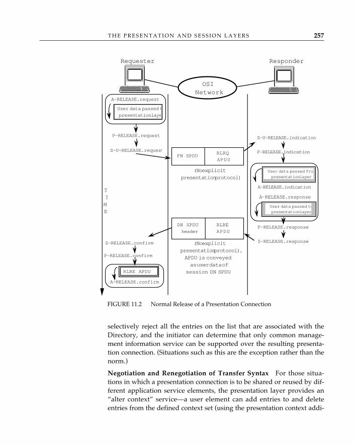
T H E P R E S E N T A T I O N A N D S E S S I O N L A Y E R S 257
selectively reject all the entries on the list that are associated with theDirectory, and the initiator can determine that only common manage-ment information service can be supported over the resulting presenta-tion connection. (Situations such as this are the exception rather than thenorm.)
Negotiation and Renegotiation of Transfer Syntax—For those situa-tions in which a presentation connection is to be shared or reused by dif-ferent application service elements, the presentation layer provides an“alter context” service—a user element can add entries to and deleteentries from the defined context set (using the presentation context addi-
FIGURE 11.2 Normal Release of a Presentation Connection
A-RELEASE.request
P-RELEASE.confirm
User data passed t
presentation laye
TIME
ResponderRequester
RLRQ
APDU
P-RELEASE.request
FN SPDU
User data receivedfrom presentation lay
P-RELEASE.indication
User data passedto presentation laye
A-RELEASE.indication
A-RELEASE.response
P-RELEASE.responseRLRE
APDU
DN SPDU
header
OSINetwork
(No explicitpresentation protocol),APDU is conveyedas user data of
session DN SPDU
S-U-RELEASE.request
S-RELEASE.confirm
RLRE APDU
A-RELEASE.confirm
(No explicitpresentation protocol)
S-U-RELEASE.indication
User data passed frompresentation layer
User data passed topresentation layer
S-RELEASE.response
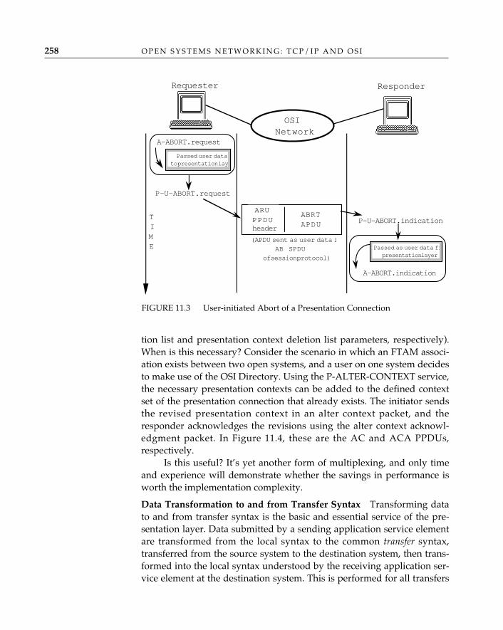
O P E N S Y S T E M S N E T W O R K I N G : T C P / I P A N D O S I258
tion list and presentation context deletion list parameters, respectively).When is this necessary? Consider the scenario in which an FTAM associ-ation exists between two open systems, and a user on one system decidesto make use of the OSI Directory. Using the P-ALTER-CONTEXT service,the necessary presentation contexts can be added to the defined contextset of the presentation connection that already exists. The initiator sendsthe revised presentation context in an alter context packet, and theresponder acknowledges the revisions using the alter context acknowl-edgment packet. In Figure 11.4, these are the AC and ACA PPDUs,respectively.
Is this useful? It’s yet another form of multiplexing, and only timeand experience will demonstrate whether the savings in performance isworth the implementation complexity.
Data Transformation to and from Transfer Syntax—Transforming datato and from transfer syntax is the basic and essential service of the pre-sentation layer. Data submitted by a sending application service elementare transformed from the local syntax to the common transfer syntax,transferred from the source system to the destination system, then trans-formed into the local syntax understood by the receiving application ser-vice element at the destination system. This is performed for all transfers
A-ABORT.request
A-ABORT.indication
Passed user datato presentation lay
TIME
ResponderRequester
ABRTAPDU
P-U-ABORT.request
ARUPPDU P-U-ABORT.indication
OSINetwork
(APDU sent as user data i
AB SPDU
of session protocol)
header
Passed as user data frpresentation layer
FIGURE 11.3 User-initiated Abort of a Presentation Connection
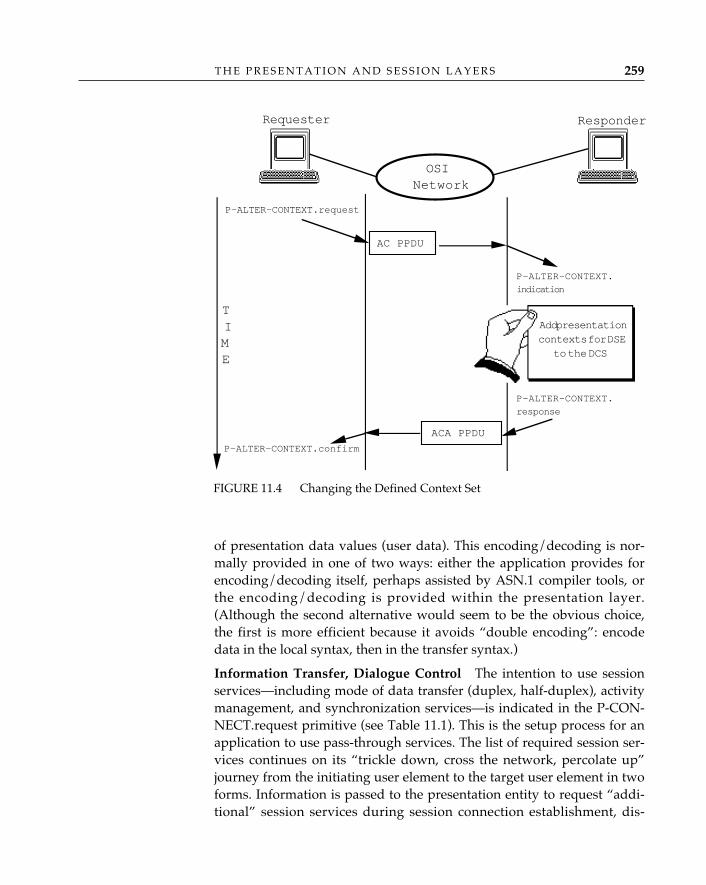
T H E P R E S E N T A T I O N A N D S E S S I O N L A Y E R S 259
of presentation data values (user data). This encoding/decoding is nor-mally provided in one of two ways: either the application provides forencoding/decoding itself, perhaps assisted by ASN.1 compiler tools, orthe encoding/decoding is provided within the presentation layer.(Although the second alternative would seem to be the obvious choice,the first is more efficient because it avoids “double encoding”: encodedata in the local syntax, then in the transfer syntax.)
Information Transfer, Dialogue Control—The intention to use sessionservices—including mode of data transfer (duplex, half-duplex), activitymanagement, and synchronization services—is indicated in the P-CON-NECT.request primitive (see Table 11.1). This is the setup process for anapplication to use pass-through services. The list of required session ser-vices continues on its “trickle down, cross the network, percolate up”journey from the initiating user element to the target user element in twoforms. Information is passed to the presentation entity to request “addi-tional” session services during session connection establishment, dis-
FIGURE 11.4 Changing the Defined Context Set
P-ALTER-CONTEXT.request
AC PPDU
P-ALTER-CONTEXT.
response
P-ALTER-CONTEXT.confirm
ACA PPDU
P-ALTER-CONTEXT.
indication
ResponderRequester
OSINetwork
Add presentationcontexts for DSE
to the DCS
TIME
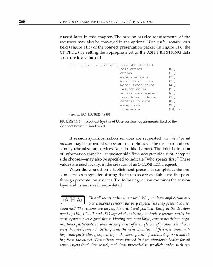
O P E N S Y S T E M S N E T W O R K I N G : T C P / I P A N D O S I260
cussed later in this chapter. The session service requirements of therequester may also be conveyed in the optional User session requirementsfield (Figure 11.5) of the connect presentation packet (in Figure 11.6, theCP PPDU) by setting the appropriate bit of the ASN.1 BITSTRING datastructure to a value of 1.
User-session-requirements ::= BIT STRING {half-duplex (0),duplex (1),expedited-data (2),minor-synchronize (3),major-synchronize (4),resynchronize (5),activity-management (6),negotiated-release (7),capability-data (8),exceptions (9),typed-data (10) }
(Source: ISO/IEC 8823: 1988)
FIGURE 11.5 Abstract Syntax of User-session-requirements field of theConnect Presentation Packet
If session synchronization services are requested, an initial serialnumber may be provided (a session user option; see the discussion of ses-sion synchronization services, later in this chapter). The initial directionof information transfer—requester side first, accepter side first, accepterside chooses—may also be specified to indicate “who speaks first.” Thesevalues are used locally, in the creation of an S-CONNECT.request.
When the connection establishment process is completed, the ses-sion services negotiated during that process are available via the pass-through presentation services. The following section examines the sessionlayer and its services in more detail.
This all seems rather unnatural. Why not have application ser-vice elements perform the very capabilities they present to user
elements? The reasons are largely historical and political. Early in the develop-ment of OSI, CCITT and ISO agreed that sharing a single reference model foropen systems was a good thing. Having two very large, consensus-driven orga-nizations participate in joint development of a single set of protocols and ser-vices, however, was not. Setting aside the issue of cultural differences, coordinat-ing—and particularly, sequencing—the development of standards proved daunt-ing from the outset. Committees were formed in both standards bodies for allseven layers (and then some), and these proceeded in parallel; under such cir-
✧AHA✧
T H E P R E S E N T A T I O N A N D S E S S I O N L A Y E R S 261
cumstances, it turned out to be impossible to define standards using a top-downor bottom-up approach. At first, coordination seemed a minor inconvenience; theOSI RM, after all, was there to guide all the standards committees. But the OSIRM itself was revised on several occasions to accommodate “pre-OSI” CCITTrecommendations such as the T.62 session protocol for teletex communicationsand the X.25 packet-level protocol. The result? Functions that arguably shouldlie in the application layer were assigned to the session layer because the X.400MHS recommendations were “ready to ship” before the application layer struc-ture was completed (see Chapter 8).
How bad is the resultant upper-layer architecture? Although pass-throughs preserve architectural purity, they are inconvenient: application ser-vice elements pass parameters for session in procedure calls to presentation,which copies or passes pointers to the same parameters in procedure calls to ses-sion, resulting in what one OSI implementer describes as “silly little no-oppass-through routines, slowing down the whole stack. . . .”3 Exaggerated? Onlyin the sense that in the overall performance of OSI implementations, this isprobably not the killer. An alternative? OSI might have adopted the “tool-kit”philosophy from the application-layer structure earlier in the process, but that’sanother case of “hindsight.”
Session LayerInformation exchange between computer systems can be viewed as hav-ing two fundamental components. The first is information transfer: mov-ing the information from its origin or source to its destination. In OSI(and TCP/IP), this aspect of information transfer is the responsibility ofthe transport service. Now, the transport service moves data betweenopen systems transparently; that is, the transport service is only responsi-ble for the transfer of an unstructured or “raw” bit stream of informationfrom one open system to another, and it doesn’t know or care whereapplication data begin and end. Applications, however, do. The secondfundamental component—preserving the structure of data defined bycommunicating application processes—belongs to the session service(ISO/IEC 8326: 1987). Thus, in addition to the expected connection man-agement services—connection establishment, release, and abort—the ses-sion layer provides application processes with the synchronization,checkpointing, and resynchronization mechanisms to organize and
3. From an electronic-mail conversation about the presentation layer with Lisa Phifer.
O P E N S Y S T E M S N E T W O R K I N G : T C P / I P A N D O S I262
impose structure on data exchanged. These are collectively referred to asdialogue-control facilities.
A further aspect of transport service transparency is that the trans-port service isn’t expected to know or care whether transport serviceusers take turns sending data or do so simultaneously, or even whetherconsecutive data are submitted by the same application. The responsibilityfor maintaining control of the conversation(s) that take place betweencommunicating application processes also belongs to the session service.The session layer provides application processes with the followingmechanisms to control the conversations, or dialogues, conducted by com-municating application processes:
• Facilities that enable applications to “take turns” exchanging dataor otherwise influence information exchange. The coordination of ahalf-duplex method of information exchange, synchronization ser-vices, and activity management services are governed by theassignment of tokens. Token-based facilities also enable applicationprocesses to coordinate the “graceful” release of associations; theyenable applications to make sure that all information transfers arecomplete before their communication is terminated (if this was theway they chose to behave).
• Facilities that allow application processes to conduct severalexchanges in the context of a single session connection. Since theunit of application exchange is called an activity (see Chapter 10),the facilities that enable applications to “distinguish between differ-ent pieces of logical work” (ISO/IEC 8326: 1987) are collectivelyreferred to as activity management.
There are more than 20 session services (see Table 11.2). For identificationduring connection negotiation and also for convenient identification byother standards (notably the presentation service, where session servicerequirements must be indicated by application entities during associationestablishment), session services that are related are logically grouped intofunctional units. Each functional unit is examined separately in the follow-ing sections.
The Kernel Functional Unit—The kernel functional unit consists of ses-sion connection establishment; “normal” data transfer (half- or full-duplex); graceful, or orderly, release; and user- and provider-initiatedabort services. All session connections require use of the kernel. Duringconnection establishment, the availability of the session services requiredby the application entities that will use the session connection is deter-
Session Services
T H E P R E S E N T A T I O N A N D S E S S I O N L A Y E R S 263
mined by the session service users (the presentation entities). There are actually four steps associated with the session functional
unit negotiation process, and the actions performed are best described byexamining the OSI upper layers together:
1. Formally, the calling application entity invokes the association con-trol, in the process identifying the application’s session require-ments for communication (see Chapter 10); these are “trickleddown” to the presentation entity in the P-CONNECT.request andto the session entity in the S-CONNECT.request. In practice, thismight be implemented as a series of procedure calls within an“association/connection management” module, with each callpassing as a “user data” parameter the protocol data unit(s) of thehigher-layer entity. Armed with the cascaded set of CONNECT.request packets, the calling session entity establishes a transportconnection (see Chapter 12), and a session connect packet (a CNSPDU) is constructed and submitted to the transport layer in a datarequest. If shorter than 512 octets, the connect presentation packet(the CP PPDU) is conveyed in the user data parameter of the ses-sion connect packet; if between 513 and 10,240 octets, it is conveyedin the extended user data parameter of the session connect packet(available in session version 2 only). Otherwise, only the first 10,240octets of the CP PPDU are sent in the extended user data parameterof the CN SPDU, followed by one or more connect data overflowpackets (CDO SPDUs). (Note that Figure 11.6 and this discussionshow only the scenario in which everything fits in a single CNSPDU.)
2. The called session entity receives the CN SPDU, parses it, and gen-erates an S-CONNECT.indication, passing among the parametersthe set of session functional units indicated by the called presenta-tion entity (and encoded in the CN SPDU), and session service userdata (containing the CP PPDU). The called presentation entityextracts the connect presentation packet (the CP PPDU) and usesthe encoded data to generate a P-CONNECT.indication (see Figure11.1 and the accompanying text). The user session requirementsfrom the calling application entity are identified to the called appli-cation entity in the indication (“percolating up” of parameters). Thecalled application entity may make adjustments to user sessionrequirements, based on (a) options left for the called applicationentity (for example, the calling application entity might have pro-posed both half- and full-duplex modes of transfer, effectively say-
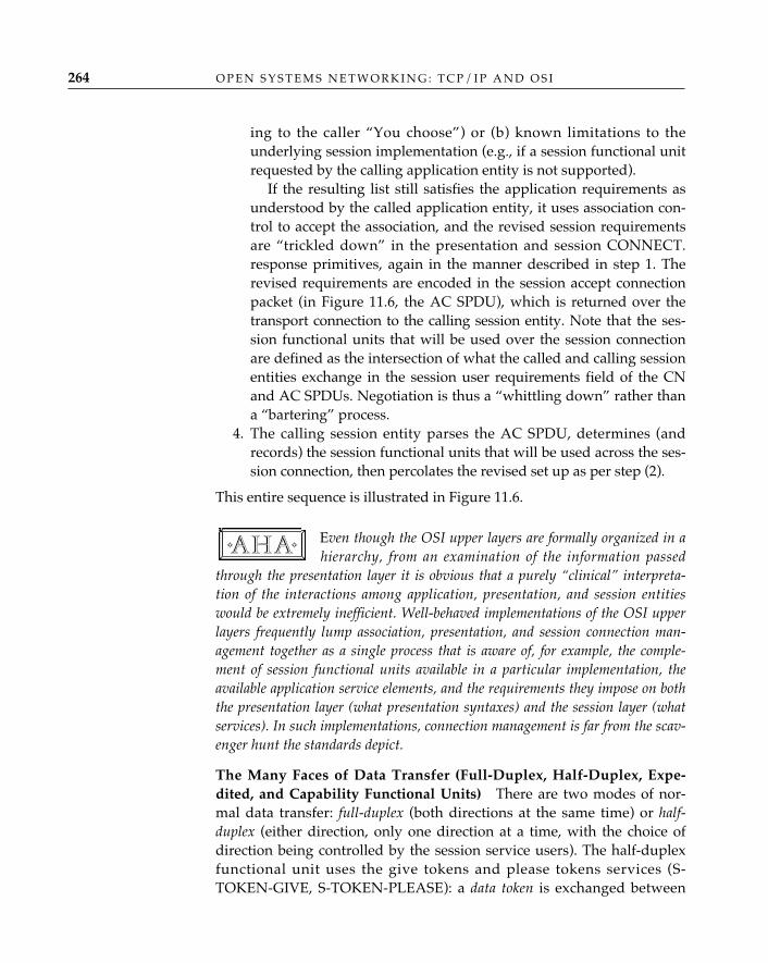
O P E N S Y S T E M S N E T W O R K I N G : T C P / I P A N D O S I264
ing to the caller “You choose”) or (b) known limitations to theunderlying session implementation (e.g., if a session functional unitrequested by the calling application entity is not supported).
If the resulting list still satisfies the application requirements asunderstood by the called application entity, it uses association con-trol to accept the association, and the revised session requirementsare “trickled down” in the presentation and session CONNECT.response primitives, again in the manner described in step 1. Therevised requirements are encoded in the session accept connectionpacket (in Figure 11.6, the AC SPDU), which is returned over thetransport connection to the calling session entity. Note that the ses-sion functional units that will be used over the session connectionare defined as the intersection of what the called and calling sessionentities exchange in the session user requirements field of the CNand AC SPDUs. Negotiation is thus a “whittling down” rather thana “bartering” process.
4. The calling session entity parses the AC SPDU, determines (andrecords) the session functional units that will be used across the ses-sion connection, then percolates the revised set up as per step (2).
This entire sequence is illustrated in Figure 11.6.
Even though the OSI upper layers are formally organized in ahierarchy, from an examination of the information passed
through the presentation layer it is obvious that a purely “clinical” interpreta-tion of the interactions among application, presentation, and session entitieswould be extremely inefficient. Well-behaved implementations of the OSI upperlayers frequently lump association, presentation, and session connection man-agement together as a single process that is aware of, for example, the comple-ment of session functional units available in a particular implementation, theavailable application service elements, and the requirements they impose on boththe presentation layer (what presentation syntaxes) and the session layer (whatservices). In such implementations, connection management is far from the scav-enger hunt the standards depict.
The Many Faces of Data Transfer (Full-Duplex, Half-Duplex, Expe-dited, and Capability Functional Units)—There are two modes of nor-mal data transfer: full-duplex (both directions at the same time) or half-duplex (either direction, only one direction at a time, with the choice ofdirection being controlled by the session service users). The half-duplexfunctional unit uses the give tokens and please tokens services (S-TOKEN-GIVE, S-TOKEN-PLEASE): a data token is exchanged between
✧AHA✧
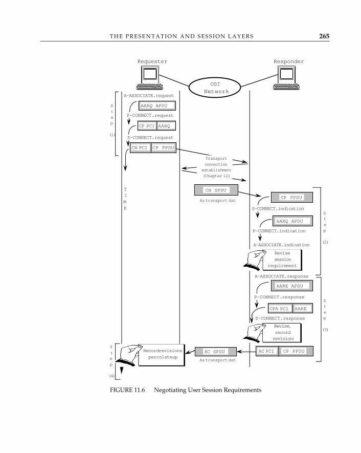
T H E P R E S E N T A T I O N A N D S E S S I O N L A Y E R S 265
FIGURE 11.6 Negotiating User Session Requirements
A-ASSOCIATE.request
A-ASSOCIATE.indication
AARQ APDU
TIME
ResponderRequester
AARQ
P-CONNECT.request
CP PCI
AARQ APDU
AARE APDU
OSINetwork
S-CONNECT.request
CP PPDUCN PCI
Transport
connection
establishment
(Chapter 12)
CN SPDU
S-CONNECT.indication
CP PPDU
P-CONNECT.indication
As transport data
A-ASSOCIATE.response
P-CONNECT.response
AARE
CP PPDUAC PCI
CPA PCI
S-CONNECT.response
AC SPDU
As transport data
Revisesession
requirements
Record revisionspercolate up
Revise,recordrevisions
S
t
e
p
�
(1)
S
t
e
p
�
(2)
S
t
e
p
�
(4)
S
t
e
p
�
(3)
O P E N S Y S T E M S N E T W O R K I N G : T C P / I P A N D O S I266
the two communicating session service users to control the direction ofinformation flow.
The notion of token-based data transfer is a pretty simple one: ifyou hold a token, you can use the service governed by that token (in thiscase, you can use the normal session data service); if you don’t have thedata token, you can request it using the please tokens service, or you canwait until the data token is yielded via the give tokens service, but youcan’t use the normal session data service until you hold the data token.
There are several ways to bypass the data token. In addition to thenormal data transfer service, there is an expedited data transfer service.Expedited data are uninhibited by token/flow control but extremely lim-ited in size (a mere 14 bytes). Originally, this data service was perceivedto facilitate virtual terminal services, but outside of this, it’s not especiallyuseful, particularly since virtually nothing can be BER-encoded in 14 orfewer bytes. Typed data transfer can be used even if you don’t hold thedata token; it’s sort of a “token be damned, I’m sending data” service. Ofcourse, restrictions apply: the typed data service is available only whenthe half-duplex mode is selected. It is used by commitment, concurrency,and recovery (ISO/IEC 9804: 1990) and the Virtual Terminal (VT; ISO/IEC 9040: 1990). CCR uses typed data to request a restart, whereasVirtual Terminal uses typed data to switch VT profiles. Both CCR and VTuse the half-duplex mode and clearly find occasions when it might havebeen wiser to use full-duplex, if only to have it available for exceptioncases. (This probably argues strongly for having standardized a full-duplex-only session service rather than a full-duplex service plus a half-duplex service with a patchwork exception service.)
A fourth data functional unit, capability data, is best understood, andonly applicable, in the context of activity management.
Activity Management Functional Unit—Chapter 10 discusses how theRT-TRANSFER service accepts arbitrarily large user data from a user ele-ment and treats each submission as a separate transfer activity (an indi-vidual application protocol data unit). At the session layer, the activityconcept is preserved: APDUs submitted to the presentation layer in P-DATA.requests can be distinguished as individual activities by using theservices that comprise the activity management functional unit. In particu-lar, activity services are used to identify the beginning and end of anactivity (S-ACTIVITY-START, S-ACTIVITY-END), to interrupt and laterresume an activity (S-ACTIVITY-INTERRUPT, S-ACTIVITY-RESUME),and to discard an ongoing activity, (a transfer that for some reason hasbecome expendable and can be trashed [S-ACTIVITY-DISCARD]).
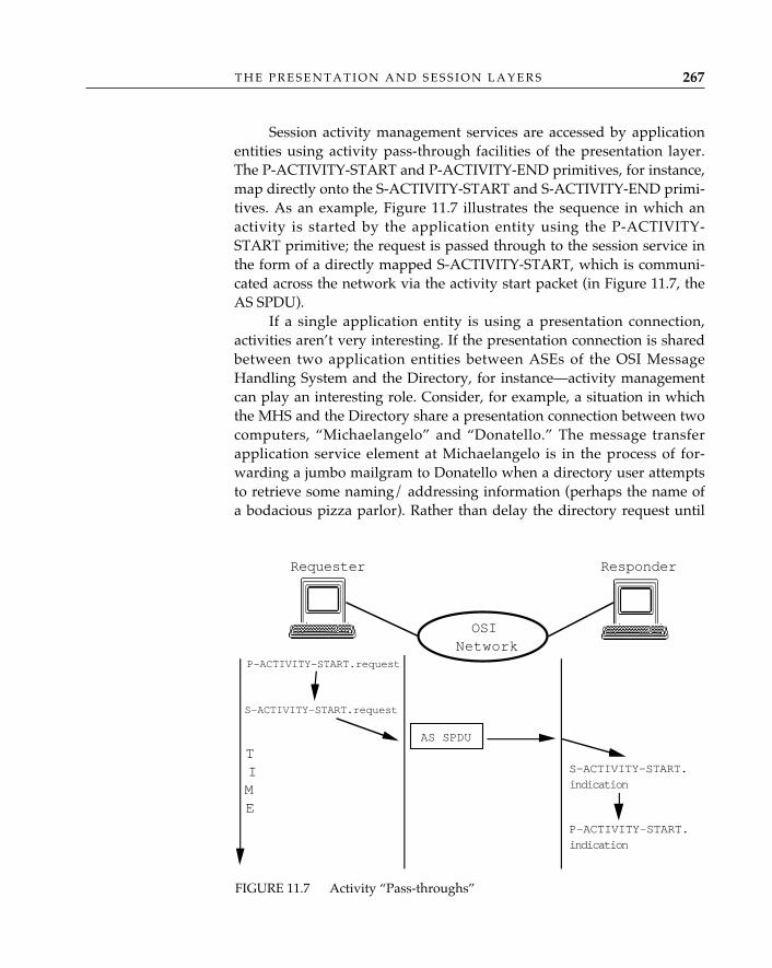
T H E P R E S E N T A T I O N A N D S E S S I O N L A Y E R S 267
Session activity management services are accessed by applicationentities using activity pass-through facilities of the presentation layer.The P-ACTIVITY-START and P-ACTIVITY-END primitives, for instance,map directly onto the S-ACTIVITY-START and S-ACTIVITY-END primi-tives. As an example, Figure 11.7 illustrates the sequence in which anactivity is started by the application entity using the P-ACTIVITY-START primitive; the request is passed through to the session service inthe form of a directly mapped S-ACTIVITY-START, which is communi-cated across the network via the activity start packet (in Figure 11.7, theAS SPDU).
If a single application entity is using a presentation connection,activities aren’t very interesting. If the presentation connection is sharedbetween two application entities between ASEs of the OSI MessageHandling System and the Directory, for instance—activity managementcan play an interesting role. Consider, for example, a situation in whichthe MHS and the Directory share a presentation connection between twocomputers, “Michaelangelo” and “Donatello.” The message transferapplication service element at Michaelangelo is in the process of for-warding a jumbo mailgram to Donatello when a directory user attemptsto retrieve some naming/ addressing information (perhaps the name ofa bodacious pizza parlor). Rather than delay the directory request until
FIGURE 11.7 Activity “Pass-throughs”
AS SPDU
ResponderRequester
OSINetwork
S-ACTIVITY-START.request
P-ACTIVITY-START.request
P-ACTIVITY-START.indication
S-ACTIVITY-START.indication
TIME
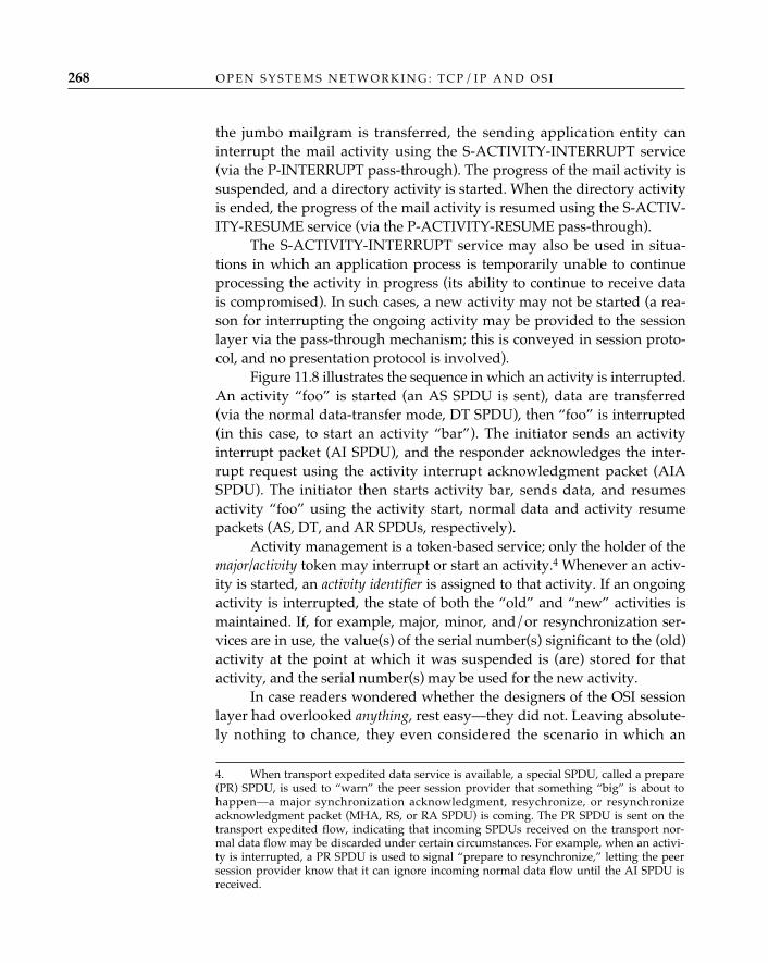
O P E N S Y S T E M S N E T W O R K I N G : T C P / I P A N D O S I268
the jumbo mailgram is transferred, the sending application entity caninterrupt the mail activity using the S-ACTIVITY-INTERRUPT service(via the P-INTERRUPT pass-through). The progress of the mail activity issuspended, and a directory activity is started. When the directory activityis ended, the progress of the mail activity is resumed using the S-ACTIV-ITY-RESUME service (via the P-ACTIVITY-RESUME pass-through).
The S-ACTIVITY-INTERRUPT service may also be used in situa-tions in which an application process is temporarily unable to continueprocessing the activity in progress (its ability to continue to receive datais compromised). In such cases, a new activity may not be started (a rea-son for interrupting the ongoing activity may be provided to the sessionlayer via the pass-through mechanism; this is conveyed in session proto-col, and no presentation protocol is involved).
Figure 11.8 illustrates the sequence in which an activity is interrupted.An activity “foo” is started (an AS SPDU is sent), data are transferred(via the normal data-transfer mode, DT SPDU), then “foo” is interrupted(in this case, to start an activity “bar”). The initiator sends an activityinterrupt packet (AI SPDU), and the responder acknowledges the inter-rupt request using the activity interrupt acknowledgment packet (AIASPDU). The initiator then starts activity bar, sends data, and resumesactivity “foo” using the activity start, normal data and activity resumepackets (AS, DT, and AR SPDUs, respectively).
Activity management is a token-based service; only the holder of themajor/activity token may interrupt or start an activity.4 Whenever an activ-ity is started, an activity identifier is assigned to that activity. If an ongoingactivity is interrupted, the state of both the “old” and “new” activities ismaintained. If, for example, major, minor, and/or resynchronization ser-vices are in use, the value(s) of the serial number(s) significant to the (old)activity at the point at which it was suspended is (are) stored for thatactivity, and the serial number(s) may be used for the new activity.
In case readers wondered whether the designers of the OSI sessionlayer had overlooked anything, rest easy—they did not. Leaving absolute-ly nothing to chance, they even considered the scenario in which an
4. When transport expedited data service is available, a special SPDU, called a prepare(PR) SPDU, is used to “warn” the peer session provider that something “big” is about tohappen—a major synchronization acknowledgment, resychronize, or resynchronizeacknowledgment packet (MHA, RS, or RA SPDU) is coming. The PR SPDU is sent on thetransport expedited flow, indicating that incoming SPDUs received on the transport nor-mal data flow may be discarded under certain circumstances. For example, when an activi-ty is interrupted, a PR SPDU is used to signal “prepare to resynchronize,” letting the peersession provider know that it can ignore incoming normal data flow until the AI SPDU isreceived.
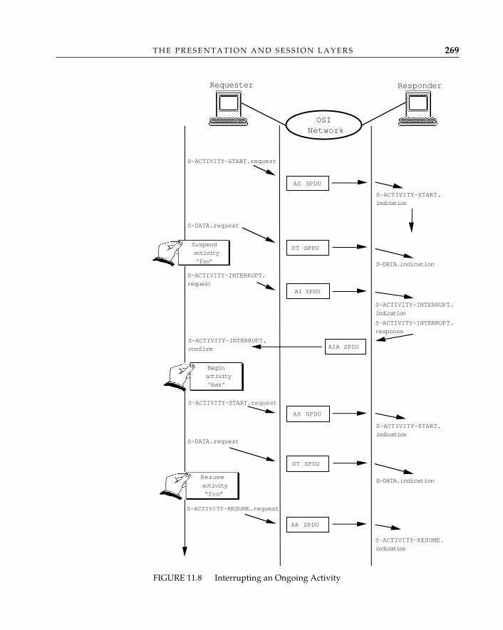
T H E P R E S E N T A T I O N A N D S E S S I O N L A Y E R S 269
S-ACTIVITY-INTERRUPT.
response
AS SPDU
ResponderRequester
OSINetwork
S-ACTIVITY-START.request
S-ACTIVITY-START.
indication
S-DATA.request
DT SPDU
S-DATA.indication
S-ACTIVITY-INTERRUPT.
requestAI SPDU
Suspend
activity
"foo"
S-ACTIVITY-INTERRUPT.
confirm AIA SPDU
Begin
activity
"bar"
S-ACTIVITY-INTERRUPT.
indication
AS SPDU
S-ACTIVITY-START.request
S-ACTIVITY-START.
indicationS-DATA.request
DT SPDU
S-DATA.indicationResume
activity
“foo”
S-ACTIVITY-RESUME.request
AR SPDU
S-ACTIVITY-RESUME.
indication
FIGURE 11.8 Interrupting an Ongoing Activity
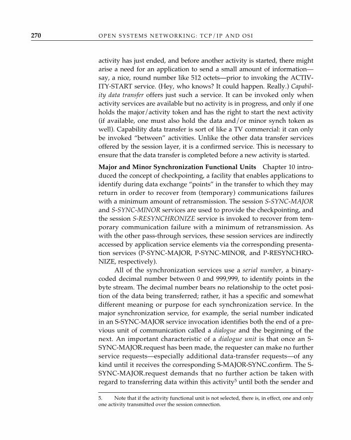
O P E N S Y S T E M S N E T W O R K I N G : T C P / I P A N D O S I270
activity has just ended, and before another activity is started, there mightarise a need for an application to send a small amount of information—say, a nice, round number like 512 octets—prior to invoking the ACTIV-ITY-START service. (Hey, who knows? It could happen. Really.) Capabil-ity data transfer offers just such a service. It can be invoked only whenactivity services are available but no activity is in progress, and only if oneholds the major/activity token and has the right to start the next activity(if available, one must also hold the data and/or minor synch token aswell). Capability data transfer is sort of like a TV commercial: it can onlybe invoked “between” activities. Unlike the other data transfer servicesoffered by the session layer, it is a confirmed service. This is necessary toensure that the data transfer is completed before a new activity is started.
Major and Minor Synchronization Functional Units—Chapter 10 intro-duced the concept of checkpointing, a facility that enables applications toidentify during data exchange “points” in the transfer to which they mayreturn in order to recover from (temporary) communications failureswith a minimum amount of retransmission. The session S-SYNC-MAJORand S-SYNC-MINOR services are used to provide the checkpointing, andthe session S-RESYNCHRONIZE service is invoked to recover from tem-porary communication failure with a minimum of retransmission. Aswith the other pass-through services, these session services are indirectlyaccessed by application service elements via the corresponding presenta-tion services (P-SYNC-MAJOR, P-SYNC-MINOR, and P-RESYNCHRO-NIZE, respectively).
All of the synchronization services use a serial number, a binary-coded decimal number between 0 and 999,999, to identify points in thebyte stream. The decimal number bears no relationship to the octet posi-tion of the data being transferred; rather, it has a specific and somewhatdifferent meaning or purpose for each synchronization service. In themajor synchronization service, for example, the serial number indicatedin an S-SYNC-MAJOR service invocation identifies both the end of a pre-vious unit of communication called a dialogue and the beginning of thenext. An important characteristic of a dialogue unit is that once an S-SYNC-MAJOR.request has been made, the requester can make no furtherservice requests—especially additional data-transfer requests—of anykind until it receives the corresponding S-MAJOR-SYNC.confirm. The S-SYNC-MAJOR.request demands that no further action be taken withregard to transferring data within this activity5 until both the sender and
5. Note that if the activity functional unit is not selected, there is, in effect, one and onlyone activity transmitted over the session connection.
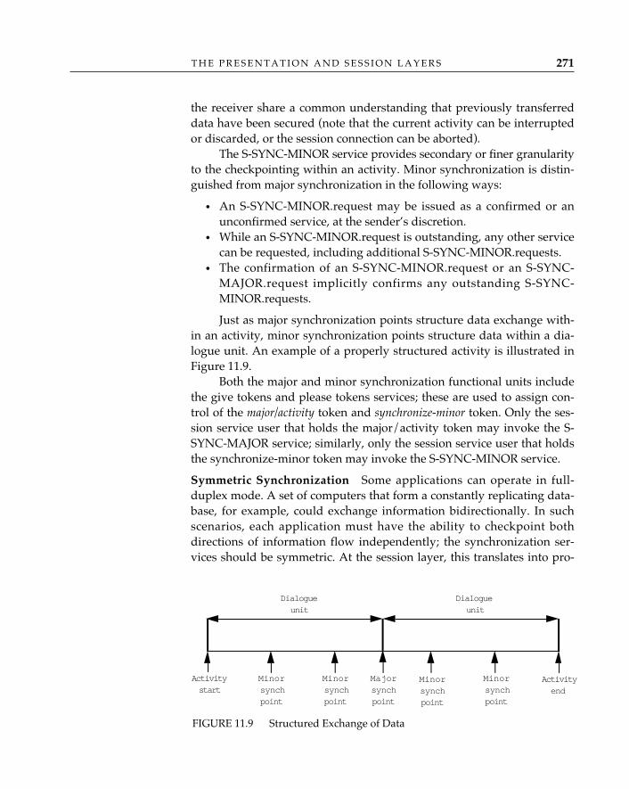
T H E P R E S E N T A T I O N A N D S E S S I O N L A Y E R S 271
the receiver share a common understanding that previously transferreddata have been secured (note that the current activity can be interruptedor discarded, or the session connection can be aborted).
The S-SYNC-MINOR service provides secondary or finer granularityto the checkpointing within an activity. Minor synchronization is distin-guished from major synchronization in the following ways:
• An S-SYNC-MINOR.request may be issued as a confirmed or anunconfirmed service, at the sender’s discretion.
• While an S-SYNC-MINOR.request is outstanding, any other servicecan be requested, including additional S-SYNC-MINOR.requests.
• The confirmation of an S-SYNC-MINOR.request or an S-SYNC-MAJOR.request implicitly confirms any outstanding S-SYNC-MINOR.requests.
Just as major synchronization points structure data exchange with-in an activity, minor synchronization points structure data within a dia-logue unit. An example of a properly structured activity is illustrated inFigure 11.9.
Both the major and minor synchronization functional units includethe give tokens and please tokens services; these are used to assign con-trol of the major/activity token and synchronize-minor token. Only the ses-sion service user that holds the major/activity token may invoke the S-SYNC-MAJOR service; similarly, only the session service user that holdsthe synchronize-minor token may invoke the S-SYNC-MINOR service.
Symmetric Synchronization—Some applications can operate in full-duplex mode. A set of computers that form a constantly replicating data-base, for example, could exchange information bidirectionally. In suchscenarios, each application must have the ability to checkpoint bothdirections of information flow independently; the synchronization ser-vices should be symmetric. At the session layer, this translates into pro-
FIGURE 11.9 Structured Exchange of Data
Activityend
Activitystart
Majorsynchpoint
Minorsynchpoint
Dialogueunit
Dialogueunit
Minorsynchpoint
Minorsynchpoint
Minorsynchpoint
O P E N S Y S T E M S N E T W O R K I N G : T C P / I P A N D O S I272
viding a capability for both session service users to insert checkpointsinto their “send” flow. When symmetric synchronization is used, a ses-sion entity maintains two serial numbers—one to checkpoint what itsends and one to checkpoint what it receives. ISO/IEC 8326 Addendum1: 1987 and ISO/IEC 8327 Addendum 1: 1987 identify the extensions tothe major and minor synchronization services to accommodate symmet-ric synchronization. Basically, two serial numbers are identified/ negoti-ated/exchanged at connect time and during activity start or re-sume. Thevalues of both serial numbers are used to identify a major synchroniza-tion point or an activity end/interrupt. If resynchronization services areselected, resynchronization can be invoked independently on eitherdirection of information flow or simultaneously (here, both serial num-bers must be provided).
The original session service and protocol standards weredesigned to be compatible with the CCITT Recommendation
T.62 session protocol for Teletex services, and the agreement between ISO andthe CCITT was that the 1984 X.215/X.225 recommendations and the ISO/IEC8326/8327 session standards would contain identical text. Now, T.62 sessionservices were designed to operate in a half-duplex mode. Since only one of thesession service users transferred data at a time, there was a need for only one ses-sion synchronization serial number. When full-duplex operations were intro-duced into the session standard, a second serial number was required to enablesession service users to control each direction of information flow independently—to operate minor synchronization and resynchronization services. This is all welland good, but the timing of this “discovery” was unfortunate. Since CCITTclosed the 1984 study period while symmetric synchronization was still understudy, the Red Book versions of the CCITT recommendations and the ISO ses-sion standards were published without it. Symmetric synchronization servicesand protocol were introduced as addenda to the session service (ISO/IEC 8326Addendum 1: 1987) and protocol (ISO/IEC 8327 Addendum 1: 1987) and in the1988 Blue Book recommendations.
Resynchronize Functional Unit—The S-RESYNCHRONIZE service isused to:
• Recover from temporary loss of a transport connection with a mini-mum of retransmission. Here, the restart option is indicated in theS-RESYNCHRONIZE.request and conveyed in the session resyn-chronize packets.
• Discard or abandon data hitherto associated with the current dia-logue unit.
✧AHA✧

T H E P R E S E N T A T I O N A N D S E S S I O N L A Y E R S 273
• Set the synchronization-point serial number to any valid value.
In all forms of the S-RESYNCHRONIZE service, the requester maypropose a (new) assignment for the available tokens (or it may indicatethat the accepter is allowed to assign token ownership). In the case of a“restart” request, the requester indicates the serial number at which therestart is to commence; it is effectively saying, “I’m confident that thetransfer state is reliable to up to this point; let’s resume transfer here.” Theaccepter sets the lowest serial number to which a synchronization pointconfirmation is expected; it also sets the next serial number expected to therestart serial number indicated in the session resynchronize (restart) pack-et (RS-r SPDU). At this point, the accepter has modified its state machineto reflect that of the requester, so it sends a resynchronize (restart)acknowledgment packet (the RA-r SPDU). Upon receiving the RA-rSPDU, the requester may retransmit data (see Figure 11.10). The acceptermay discard any data secured and associated with a serial number greaterthan the serial number indicated as the restart serial number; from therequester’s perspective, these are “suspect” or unconfirmed data.
In the case of an “abandon” request, the requester does not send aserial number, since it’s effectively saying, “Let’s start over.” In responseto the session resynchronize (abandon) packet (the RS-a SPDU), theaccepter returns a session resynchronize (abandon) acknowledgmentpacket (the RA-a SPDU), discards all data of this dialogue unit that werepreviously secured, and awaits “new” transfer. In this case, the accepterexpects to proceed as if resynchronization hadn’t happened at all. Theserial number indicated in the next major/minor synchronizationrequest will be the “next expected serial number” indicated in the RS-aSPDU, and the lowest serial number to which a resynchronization restartmay be set becomes 0.
In the case of a “set” request, the requester selects any valid serialnumber and sends this in an RS-s SPDU. The accepter sets the nextexpected serial number to the value received in the RS-s SPDU, andreturns an RA-s SPDU. Following receipt of the RA-s SPDU and confir-mation of the S-RESYNCHRONIZE.request, the requester will use the“set value” in subsequent synchronization requests, and the lowest serialnumber to which a resynchronization restart may be set becomes 0.
Like the major and minor synchronization services, applicationentities access the session resynchronization service via a pass-throughservice of the presentation layer (P-RESYNCHRONIZE).
Exceptions Functional Unit—Considering how complicated the sessionprotocol can be, it seems only fitting that a service was designed to allow
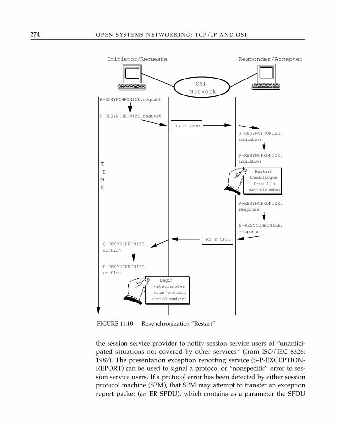
O P E N S Y S T E M S N E T W O R K I N G : T C P / I P A N D O S I274
the session service provider to notify session service users of “unantici-pated situations not covered by other services” (from ISO/IEC 8326:1987). The presentation exception reporting service (S-P-EXCEPTION-REPORT) can be used to signal a protocol or “nonspecific” error to ses-sion service users. If a protocol error has been detected by either sessionprotocol machine (SPM), that SPM may attempt to transfer an exceptionreport packet (an ER SPDU), which contains as a parameter the SPDU
FIGURE 11.10 Resynchronization “Restart”
P-RESYNCHRONIZE.
indication
S-RESYNCHRONIZE.
response
RS-r SPDU
Responder/AccepterInitiator/Requester
OSINetwork
S-RESYNCHRONIZE.request
P-RESYNCHRONIZE.request
S-RESYNCHRONIZE.
indication
S-RESYNCHRONIZE.
confirm
RS-r SPDU
Restart
the dialogue
from this
serial number
P-RESYNCHRONIZE.
confirm
Begin
data transfer
from "restart
serial number"
P-RESYNCHRONIZE.
response
TIME
T H E P R E S E N T A T I O N A N D S E S S I O N L A Y E R S 275
that the session protocol machine has identified as objectionable.Following an indication of this sort, the session service users are encour-aged to resynchronize, interrupt or discard the current activity, or abortthe session connection. (Note that only if the transfer and interpretationof the ER SPDU are successful will both session service users receive anindication that an exception condition has been detected.)
An exception reporting service is also available to the session ser-vice users. If a session service user encounters an exception condition, itcan issue an S-U-EXCEPTION.request. The local session protocolmachine will attempt to transfer an exception data packet (an ED SPDU)to the remote SPM containing an indication of the sort of physical, emo-tional, or psychological problem the requester is experiencing. If the EDSPDU arrives and can be processed, an S-U-EXCEPTION.indication maybe generated.
Although it is possible to attempt to resynchronize, interrupt,or discard the current activity, or even yield tokens to a session
service user that thinks it can solve the problem if only it could send data, it’sgenerally a good idea for the session service user to follow exception servicerequests with an abort. Dynamic, self-recovering protocol implementations arehard to find.
Negotiated Release Functional Unit—The negotiated release functionalunit consists of orderly release and the give tokens and please tokens ser-vices. The orderly release service (S-RELEASE) resembles the gracefulclose offered by TCP (see Chapter 12); both session service users cooper-ate to ensure that all data in transit have been delivered (acknowledged)before the session connection is closed. Orderly release is influenced bythe release token; if an S-RELEASE.indication arrives and the release tokenis available, the accepter may refuse to release the connection (once againbelying the term accepter). This situation might occur when a mail appli-cation “foo” has nothing more to send to its peer “bar” and wishes torelease the association, but “bar” still has messages to forward to “foo”.
Orderly release is initiated using the S-RELEASE.request serviceprimitive. A session finish packet (an FN SPDU) is sent to the accepter; ifthe accepter agrees to close the session connection, it returns a sessiondisconnect packet (DN SPDU), confirming the S-RELEASE. A transportdisconnect parameter in the DN SPDU may be used to indicate whetherthe transport connection hitherto supporting this session connection is tobe reused, and the session protocol machine will proceed according to
✧AHA✧
O P E N S Y S T E M S N E T W O R K I N G : T C P / I P A N D O S I276
what is indicated. If the accepter wishes to maintain the session connec-tion, it responds to the FN SPDU with, appropriately, a session not fin-ished packet (NF SPDU), resulting in a rejection of the S-RELEASE ser-vice. This is permitted only if the negotiated release functional unit wasaccepted when the session was established.
Abort Services—The session abort service (S-U-ABORT) of the kernelfunctional unit supports the abort services of the association control ser-vice element and the presentation layer. What more can one say? Anapplication entity has observed that things have gone to hell in a hand-basket and indicates that it wants to tear down the connection. The pre-sentation abort service (S-P-ABORT) is used to indicate that somethingdisastrous has occurred in or below the session layer; the protocol imple-mentation is broken, for example, or the transport connection has discon-nected. If the latter is true, the session layer initiates an S-P-ABORT.indi-cation to notify the presentation layer.
Most of the descriptions of the session protocol have been vicious andunkind. Regrettably, they are deserved, and no amount of historical per-spective can alter the fact that the session protocol, from encoding tooperation, is neither elegant nor efficient.6 In version 1, there are 29 statesin the protocol machine, further complicated by 75 predicates—and thisdoesn’t take into account additions to accommodate unlimited user data(ISO/IEC 8327 Addendum 2: 1987) or symmetric synchronization(ISO/IEC 8327 Addendum 1: 1987). The encoding of the session protocolitself is a “fixed-field format” lover’s worst nightmare. For starters, allsession protocol data units have the following components:
Session Protocol
6. Upon first examination, it almost appears that its creators were a divided camp, halfinsisting on a “TLV” approach similar to ASN.1, the other half insisting on specification bythe bits and bytes “as we’ve always done it in the lower layers.” The true reason is notnearly this simple. The session protocol is arguably the worst example of design by com-mittee; faced with multiple base documents to consider (one from ECMA [ECMA75], onefrom CCITT [CCITT T.62], others too embarrassing to mention), confronted with a commit-ment to align OSI and the CCITT Teletex protocols, and expected to come to closure on astandard prior to the completion of the 1984 CCITT study period, the committee collapsedunder pressure and, “in the spirit of compromise,” adopted a combination (not quite theunion) of the services of the documents under consideration. At the service level, this was asizable enough pill to swallow; the ramifications to the protocol (of course, everyone insist-ed on perpetuating their own bits as well) were nearly ruinous.
A single octet; identifies the type of SPDUA single octet; specifies the length of the SPDU in octetsAn individual or a group parameter (variable-length)(Variable-length)
SPDU identifier (SI)Length indicator (LI)Parameter identifier (PI)User information
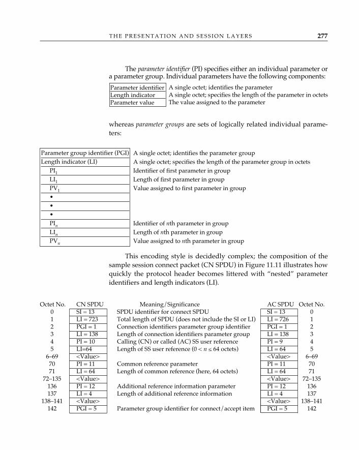
T H E P R E S E N T A T I O N A N D S E S S I O N L A Y E R S 277
The parameter identifier (PI) specifies either an individual parameter ora parameter group. Individual parameters have the following components:
whereas parameter groups are sets of logically related individual parame-ters:
This encoding style is decidedly complex; the composition of thesample session connect packet (CN SPDU) in Figure 11.11 illustrates howquickly the protocol header becomes littered with “nested” parameteridentifiers and length indicators (LI).
Octet No. CN SPDU Meaning/Significance AC SPDU Octet No.0 SI = 13 SPDU identifier for connect SPDU SI = 13 01 LI = 723 Total length of SPDU (does not include the SI or LI) LI = 726 12 PGI = 1 Connection identifiers parameter group identifier PGI = 1 23 LI = 138 Length of connection identifiers parameter group LI = 138 34 PI = 10 Calling (CN) or called (AC) SS user reference PI = 9 45 LI=64 Length of SS user reference (0 < n ≤ 64 octets) LI = 64 5
6–69 <Value> <Value> 6–6970 PI = 11 Common reference parameter PI = 11 7071 LI = 64 Length of common reference (here, 64 octets) LI = 64 71
72–135 <Value> <Value> 72–135136 PI = 12 Additional reference information parameter PI = 12 136137 LI = 4 Length of additional reference information LI = 4 137
138–141 <Value> <Value> 138–141142 PGI = 5 Parameter group identifier for connect/accept item PGI = 5 142
A single octet; identifies the parameterA single octet; specifies the length of the parameter in octetsThe value assigned to the parameter
Parameter identifier Length indicator Parameter value
A single octet; identifies the parameter groupA single octet; specifies the length of the parameter group in octetsIdentifier of first parameter in groupLength of first parameter in groupValue assigned to first parameter in group
Identifier of nth parameter in groupLength of nth parameter in groupValue assigned to nth parameter in group
Parameter group identifier (PGI)Length indicator (LI)
PI1
LI1
PV1
•••PIn
LIn
PVn
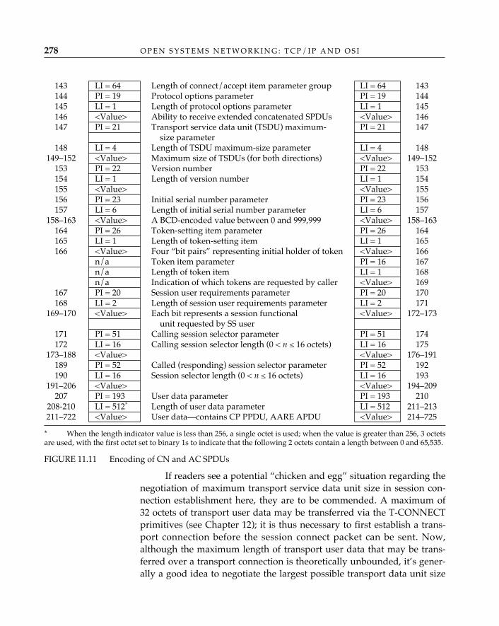
O P E N S Y S T E M S N E T W O R K I N G : T C P / I P A N D O S I278
143 LI = 64 Length of connect/accept item parameter group LI = 64 143144 PI = 19 Protocol options parameter PI = 19 144145 LI = 1 Length of protocol options parameter LI = 1 145146 <Value> Ability to receive extended concatenated SPDUs <Value> 146147 PI = 21 Transport service data unit (TSDU) maximum- PI = 21 147
size parameter148 LI = 4 Length of TSDU maximum-size parameter LI = 4 148
149–152 <Value> Maximum size of TSDUs (for both directions) <Value> 149–152153 PI = 22 Version number PI = 22 153154 LI = 1 Length of version number LI = 1 154155 <Value> <Value> 155156 PI = 23 Initial serial number parameter PI = 23 156157 LI = 6 Length of initial serial number parameter LI = 6 157
158–163 <Value> A BCD-encoded value between 0 and 999,999 <Value> 158–163164 PI = 26 Token-setting item parameter PI = 26 164165 LI = 1 Length of token-setting item LI = 1 165166 <Value> Four “bit pairs” representing initial holder of token <Value> 166
n/a Token item parameter PI = 16 167n/a Length of token item LI = 1 168n/a Indication of which tokens are requested by caller <Value> 169
167 PI = 20 Session user requirements parameter PI = 20 170168 LI = 2 Length of session user requirements parameter LI = 2 171
169–170 <Value> Each bit represents a session functional <Value> 172–173unit requested by SS user
171 PI = 51 Calling session selector parameter PI = 51 174172 LI = 16 Calling session selector length (0 < n ≤ 16 octets) LI = 16 175
173–188 <Value> <Value> 176–191189 PI = 52 Called (responding) session selector parameter PI = 52 192190 LI = 16 Session selector length (0 < n ≤ 16 octets) LI = 16 193
191–206 <Value> <Value> 194–209207 PI = 193 User data parameter PI = 193 210
208-210 LI = 512* Length of user data parameter LI = 512 211–213211–722 <Value> User data—contains CP PPDU, AARE APDU <Value> 214–725
* When the length indicator value is less than 256, a single octet is used; when the value is greater than 256, 3 octetsare used, with the first octet set to binary 1s to indicate that the following 2 octets contain a length between 0 and 65,535.
FIGURE 11.11 Encoding of CN and AC SPDUs
If readers see a potential “chicken and egg” situation regarding thenegotiation of maximum transport service data unit size in session con-nection establishment here, they are to be commended. A maximum of32 octets of transport user data may be transferred via the T-CONNECTprimitives (see Chapter 12); it is thus necessary to first establish a trans-port connection before the session connect packet can be sent. Now,although the maximum length of transport user data that may be trans-ferred over a transport connection is theoretically unbounded, it’s gener-ally a good idea to negotiate the largest possible transport data unit size
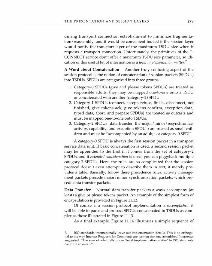
T H E P R E S E N T A T I O N A N D S E S S I O N L A Y E R S 279
during transport connection establishment to minimize fragmenta-tion/reassembly, and it would be convenient indeed if the session layerwould notify the transport layer of the maximum TSDU size when itrequests a transport connection. Unfortunately, the primitives of the T-CONNECT service don’t offer a maximum TSDU size parameter, so idi-cation of this useful bit of information is a local implementation matter.7
A Word about Concatenation— Another truly confusing aspect of thesession protocol is the notion of concatenation of session packets (SPDUs)into TSDUs. SPDUs are categorized into three groups:
1. Category-0 SPDUs (give and please tokens SPDUs) are treated asresponsible adults; they may be mapped one-to-one onto a TSDUor concatenated with another (category-2) SPDU.
2. Category-1 SPDUs (connect, accept, refuse, finish, disconnect, notfinished, give tokens ack, give tokens confirm, exception data,typed data, abort, and prepare SPDUs) are treated as outcasts andmust be mapped one-to-one onto TSDUs.
3. Category-2 SPDUs (data transfer, the major/minor/resynchronize,activity, capability, and exception SPDUs) are treated as small chil-dren and must be “accompanied by an adult,” or category-0 SPDU.
A category-0 SPDU is always the first session packet in a transportservice data unit. If basic concatenation is used, a second session packetmay be appended to the first if it comes from the set of category-2SPDUs, and if extended concatenation is used, you can piggyback multiplecategory-2 SPDUs. Here, the rules are so complicated that the sessionprotocol doesn’t even attempt to describe them in text; it merely pro-vides a table. Basically, follow these precedence rules: activity manage-ment packets precede major/minor synchronization packets, which pre-cede data transfer packets.
Data Transfer— Normal data transfer packets always accompany (atleast) a give or please tokens packet. An example of the simplest form ofencapsulation is provided in Figure 11.12.
Of course, if a session protocol implementation is accomplished, itwill be able to parse and process SPDUs concatenated in TSDUs as com-plex as those illustrated in Figure 11.13.
As a final example, Figure 11.14 illustrates a simple sequence of
7. ISO standards internationally leave out implementation details. This is so orthogo-nal to the way Internet Requests for Comments are written that one astonished Internettersuggested, “The sum of what falls under ‘local implementation matter’ in ISO standardscould fill an ocean.”
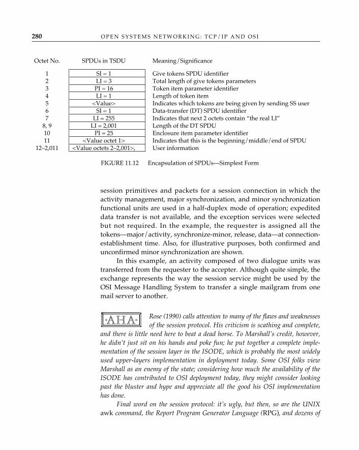
O P E N S Y S T E M S N E T W O R K I N G : T C P / I P A N D O S I280
session primitives and packets for a session connection in which theactivity management, major synchronization, and minor synchronizationfunctional units are used in a half-duplex mode of operation; expediteddata transfer is not available, and the exception services were selectedbut not required. In the example, the requester is assigned all thetokens—major/activity, synchronize-minor, release, data—at connection-establishment time. Also, for illustrative purposes, both confirmed andunconfirmed minor synchronization are shown.
In this example, an activity composed of two dialogue units wastransferred from the requester to the accepter. Although quite simple, theexchange represents the way the session service might be used by theOSI Message Handling System to transfer a single mailgram from onemail server to another.
Rose (1990) calls attention to many of the flaws and weaknessesof the session protocol. His criticism is scathing and complete,
and there is little need here to beat a dead horse. To Marshall’s credit, however,he didn’t just sit on his hands and poke fun; he put together a complete imple-mentation of the session layer in the ISODE, which is probably the most widelyused upper-layers implementation in deployment today. Some OSI folks viewMarshall as an enemy of the state; considering how much the availability of theISODE has contributed to OSI deployment today, they might consider lookingpast the bluster and hype and appreciate all the good his OSI implementationhas done.
Final word on the session protocol: it’s ugly, but then, so are the UNIXawk command, the Report Program Generator Language (RPG), and dozens of
✧AHA✧
Octet No. SPDUs in TSDU Meaning/Significance
1 SI = 1 Give tokens SPDU identifier2 LI = 3 Total length of give tokens parameters3 PI = 16 Token item parameter identifier4 LI = 1 Length of token item5 <Value> Indicates which tokens are being given by sending SS user6 SI = 1 Data-transfer (DT) SPDU identifier7 LI = 255 Indicates that next 2 octets contain “the real LI”
8, 9 LI = 2,001 Length of the DT SPDU10 PI = 25 Enclosure item parameter identifier11 <Value octet 1> Indicates that this is the beginning/middle/end of SPDU
12–2,011 <Value octets 2–2,001>, User information
FIGURE 11.12 Encapsulation of SPDUs—Simplest Form
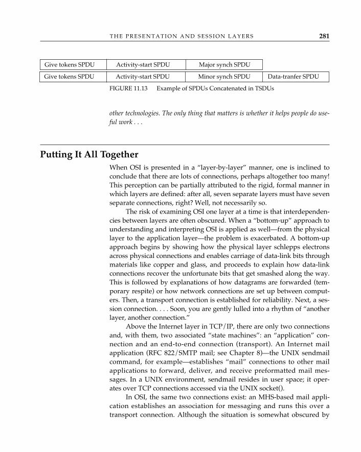
T H E P R E S E N T A T I O N A N D S E S S I O N L A Y E R S 281
other technologies. The only thing that matters is whether it helps people do use-ful work . . .
Putting It All TogetherWhen OSI is presented in a “layer-by-layer” manner, one is inclined toconclude that there are lots of connections, perhaps altogether too many!This perception can be partially attributed to the rigid, formal manner inwhich layers are defined: after all, seven separate layers must have sevenseparate connections, right? Well, not necessarily so.
The risk of examining OSI one layer at a time is that interdependen-cies between layers are often obscured. When a “bottom-up” approach tounderstanding and interpreting OSI is applied as well—from the physicallayer to the application layer—the problem is exacerbated. A bottom-upapproach begins by showing how the physical layer schlepps electronsacross physical connections and enables carriage of data-link bits throughmaterials like copper and glass, and proceeds to explain how data-linkconnections recover the unfortunate bits that get smashed along the way.This is followed by explanations of how datagrams are forwarded (tem-porary respite) or how network connections are set up between comput-ers. Then, a transport connection is established for reliability. Next, a ses-sion connection. . . . Soon, you are gently lulled into a rhythm of “anotherlayer, another connection.”
Above the Internet layer in TCP/IP, there are only two connectionsand, with them, two associated “state machines”: an “application” con-nection and an end-to-end connection (transport). An Internet mailapplication (RFC 822/SMTP mail; see Chapter 8)—the UNIX sendmailcommand, for example—establishes “mail” connections to other mailapplications to forward, deliver, and receive preformatted mail mes-sages. In a UNIX environment, sendmail resides in user space; it oper-ates over TCP connections accessed via the UNIX socket().
In OSI, the same two connections exist: an MHS-based mail appli-cation establishes an association for messaging and runs this over atransport connection. Although the situation is somewhat obscured by
FIGURE 11.13 Example of SPDUs Concatenated in TSDUs
Give tokens SPDU Activity-start SPDU Major synch SPDU
Give tokens SPDU Activity-start SPDU Minor synch SPDU Data-tranfer SPDU
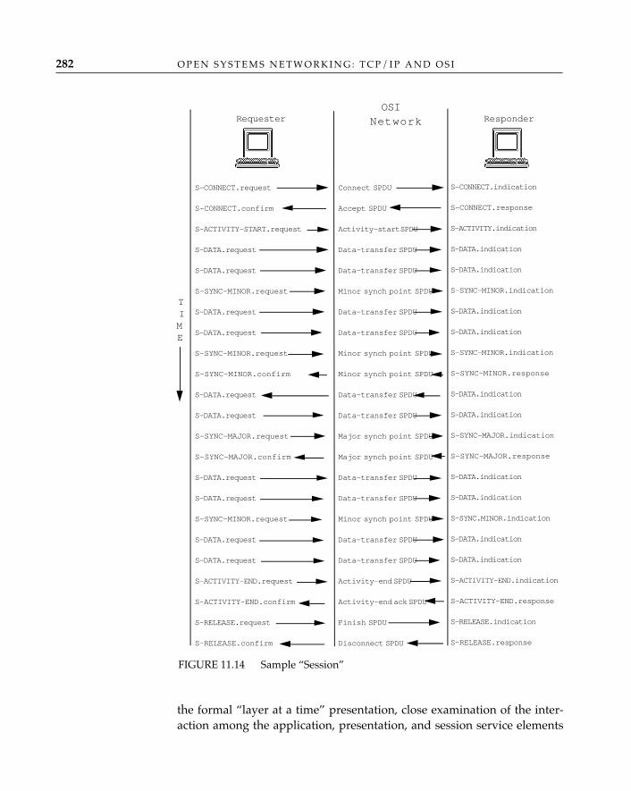
O P E N S Y S T E M S N E T W O R K I N G : T C P / I P A N D O S I282
the formal “layer at a time” presentation, close examination of the inter-action among the application, presentation, and session service elements
Requester Responder
S-CONNECT.request�S-CONNECT.confirm�S-ACTIVITY-START.request�S-DATA.request�S-DATA.request�S-SYNC-MINOR.request�S-DATA.request�S-DATA.request�S-SYNC-MINOR.request�S-SYNC-MINOR.confirm�S-DATA.request�S-DATA.request�S-SYNC-MAJOR.request�S-SYNC-MAJOR.confirm�S-DATA.request�S-DATA.request�S-SYNC-MINOR.request�S-DATA.request�S-DATA.request�S-ACTIVITY-END.request�S-ACTIVITY-END.confirm�S-RELEASE.request�S-RELEASE.confirm�
Connect SPDU�Accept SPDU�Activity-start SPDU�Data-transfer SPDU�Data-transfer SPDU�Minor synch point SPDU�Data-transfer SPDU�Data-transfer SPDU�Minor synch point SPDU�Minor synch point SPDU�Data-transfer SPDU�Data-transfer SPDU�Major synch point SPDU�Major synch point SPDU�Data-transfer SPDU�Data-transfer SPDU�Minor synch point SPDU�Data-transfer SPDU�Data-transfer SPDU�Activity-end SPDU�Activity-end ack SPDU�Finish SPDU�Disconnect SPDU
S-CONNECT.indication�S-CONNECT.response�S-ACTIVITY.indication�S-DATA.indication�S-DATA.indication�S-SYNC-MINOR.indication�S-DATA.indication�S-DATA.indication�S-SYNC-MINOR.indication�S-SYNC-MINOR.response�S-DATA.indication�S-DATA.indication�S-SYNC-MAJOR.indication�S-SYNC-MAJOR.response�S-DATA.indication�S-DATA.indication�S-SYNC.MINOR.indication�S-DATA.indication�S-DATA.indication�S-ACTIVITY-END.indication�S-ACTIVITY-END.response�S-RELEASE.indication�S-RELEASE.response
OSINetwork
TIME
FIGURE 11.14 Sample “Session”
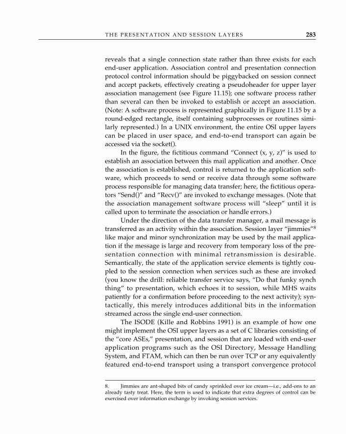
T H E P R E S E N T A T I O N A N D S E S S I O N L A Y E R S 283
reveals that a single connection state rather than three exists for eachend-user application. Association control and presentation connectionprotocol control information should be piggybacked on session connectand accept packets, effectively creating a pseudoheader for upper layerassociation management (see Figure 11.15); one software process ratherthan several can then be invoked to establish or accept an association.(Note: A software process is represented graphically in Figure 11.15 by around-edged rectangle, itself containing subprocesses or routines simi-larly represented.) In a UNIX environment, the entire OSI upper layerscan be placed in user space, and end-to-end transport can again beaccessed via the socket().
In the figure, the fictitious command “Connect (x, y, z)” is used toestablish an association between this mail application and another. Oncethe association is established, control is returned to the application soft-ware, which proceeds to send or receive data through some softwareprocess responsible for managing data transfer; here, the fictitious opera-tors “Send()” and “Recv()” are invoked to exchange messages. (Note thatthe association management software process will “sleep” until it iscalled upon to terminate the association or handle errors.)
Under the direction of the data transfer manager, a mail message istransferred as an activity within the association. Session layer “jimmies”8
like major and minor synchronization may be used by the mail applica-tion if the message is large and recovery from temporary loss of the pre-sentation connection with minimal retransmission is desirable.Semantically, the state of the application service elements is tightly cou-pled to the session connection when services such as these are invoked(you know the drill: reliable transfer service says, “Do that funky synchthing” to presentation, which echoes it to session, while MHS waitspatiently for a confirmation before proceeding to the next activity); syn-tactically, this merely introduces additional bits in the informationstreamed across the single end-user connection.
The ISODE (Kille and Robbins 1991) is an example of how onemight implement the OSI upper layers as a set of C libraries consisting ofthe “core ASEs,” presentation, and session that are loaded with end-userapplication programs such as the OSI Directory, Message HandlingSystem, and FTAM, which can then be run over TCP or any equivalentlyfeatured end-to-end transport using a transport convergence protocol
8. Jimmies are ant-shaped bits of candy sprinkled over ice cream—i.e., add-ons to analready tasty treat. Here, the term is used to indicate that extra degrees of control can beexercised over information exchange by invoking session services.
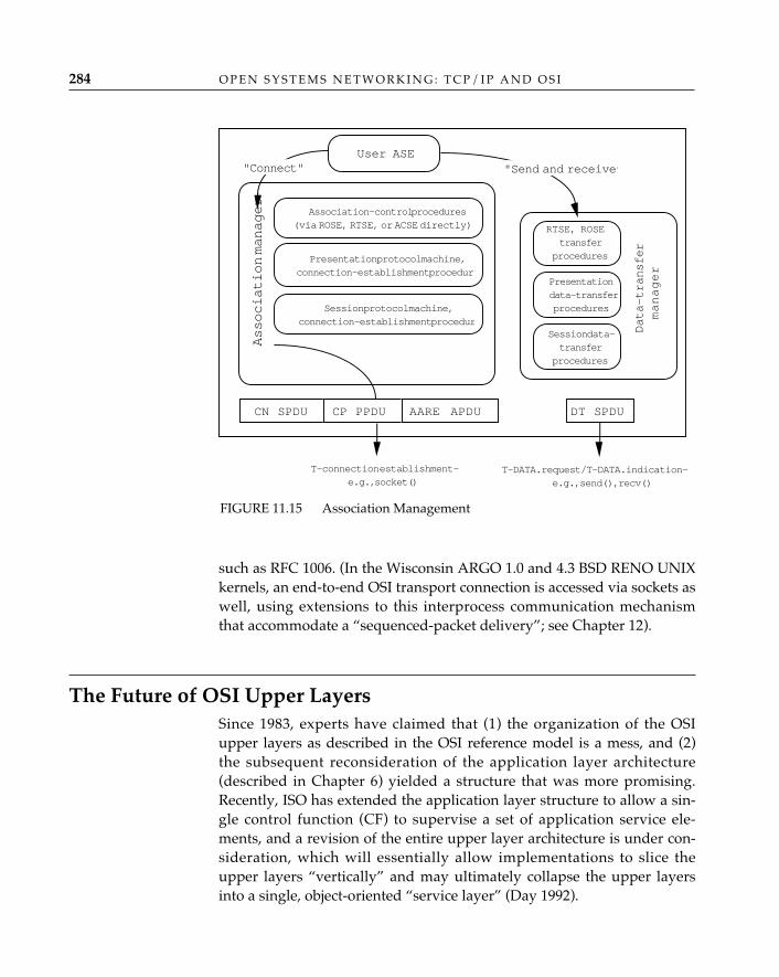
O P E N S Y S T E M S N E T W O R K I N G : T C P / I P A N D O S I284
such as RFC 1006. (In the Wisconsin ARGO 1.0 and 4.3 BSD RENO UNIXkernels, an end-to-end OSI transport connection is accessed via sockets aswell, using extensions to this interprocess communication mechanismthat accommodate a “sequenced-packet delivery”; see Chapter 12).
The Future of OSI Upper LayersSince 1983, experts have claimed that (1) the organization of the OSIupper layers as described in the OSI reference model is a mess, and (2)the subsequent reconsideration of the application layer architecture(described in Chapter 6) yielded a structure that was more promising.Recently, ISO has extended the application layer structure to allow a sin-gle control function (CF) to supervise a set of application service ele-ments, and a revision of the entire upper layer architecture is under con-sideration, which will essentially allow implementations to slice theupper layers “vertically” and may ultimately collapse the upper layersinto a single, object-oriented “service layer” (Day 1992).
FIGURE 11.15 Association Management
Association manager
Association-control procedures(via ROSE, RTSE, or ACSE directly)
Presentation protocol machine,connection-establishment procedur
Session protocol machine,connection-establishment procedur
"Connect"
CN SPDU CP PPDU AARE APDU
T-connection establishment—e.g., socket( )
User ASE"Send and receive”
Presentationdata-transferprocedures
Session data-transfer
procedures
Data-transfer
manager
DT SPDU
T-DATA.request/T-DATA.indication—e.g., send(), recv()
RTSE, ROSEtransfer
procedures
T H E P R E S E N T A T I O N A N D S E S S I O N L A Y E R S 285
The extended application layer structure (XALS) and revised OSIupper layer architecture under study in ISO define application serviceobjects (ASOs) that will contain multiple application service elements,some of these formed by grouping session functional units into applica-tion service elements and eliminating the session layer entirely. Theexisting presentation layer functionality will be subsumed within a newassociation control service element, which will offer an A-DATA service,and the presentation layer will be removed from the OSI reference modelas well. The extended A2CSE (ASO association control service element)will then be bolted directly on top of the transport layer.
These changes affect a number of OSI standards, including the ref-erence model, and they won’t happen overnight. The currentwisdom/optimism is that these moves will resolve some of the frequentlycriticized upper layer implementation difficulties. OSI upper layer imple-mentations are criticized for having considerable overhead. The ISODE7.0 implementation, for example, binds the entire session service libraryto each application process at run time; a possible result of rearchitectingthe upper layer structure might be that future OSI-basedprograms/processes would be smaller, since the new ASOs would haveonly a subset of session functional units (basic synchronization and basiccombined subsets rise from the ashes!).
There is, of course, a downside to these proposals; namely, thetremendous impact they would have on the few daring vendors
that have ventured forth into OSI upper layers product deployment. Since, forreasons of efficiency already noted, OSI upper layer implementations tend to beclosely coupled with the application service element, reorganization and reimple-mentation will be painful. Also, eliminating a layer of protocol header will wreakhavoc on interoperability—the original and continuing goal of OSI, remem-ber?—and require an extensive migration and coexistence plan. The moral?Prototype and measure, until a truly worthwhile “skinny-stack” approachemerges that supports a business case for transition from existing OSI upperlayers to the new world.
ConclusionThis chapter concludes the discussion of the OSI upper layers. Havingfirst examined application services at a conceptual and “features” levelin Chapters 7, 8, and 9 (introducing directories, e-mail, and networkmanagement), the authors then discussed the service elements on which
✧AHA✧
O P E N S Y S T E M S N E T W O R K I N G : T C P / I P A N D O S I286
distributed applications rely to provide such end services—in particular,application connection establishment, remote operations, and reliabletransfer. This chapter has demonstrated how certain functions that appli-cation service elements provide to user elements or “specific” applicationservice elements—the checkpointing, turn management, and activity man-agement services that constitute reliable transfer—are performed at thesession layer and how these are accessed via “pass-through” servicesprovided by the presentation layer. Having completed a layer-by-layerdescription of the OSI upper layers, the authors “put it all together” anddiscussed how the existence of seven layers is not a mandate for (at least)seven connections—the interdependencies between the OSI upper layersmay be exploited in prudent implementations, and everything in OSI“from session and above” can be implemented as a single connection.The chapter concludes with some insights into how implementationexperience and hindsight may contribute to future refinements in the OSIupper layer structure.

PA R T F O U R
MIDDLE LAYERS
12 THE TRANSPORT LAYER
The transport layer is the basic end-to-end building block of host networking.Everything above the transport layer is distributed-application–oriented;everything below the transport layer is transmission-network–oriented. Inthe work on OSI, the upper layers have tended to be the province of peoplewith a computer systems (particularly operating systems) background; thelower layers, of people with an electrical engineering (particularly transmis-sion systems) background. The imperfect alignment of the very differentperspectives of the “computer people” and the “telecommunications peo-ple” has led to the definition of five different classes of transport protocol inOSI, each one tailored to a particular vision of the way in which hosts areproperly interconnected by networks. The work on TCP/IP, on the otherhand, was carried out by a relatively small group of people who managedto avoid being identified as “upper layer” or “lower layer” until long afterthe fact. This group agreed on a single model for network interconnectionand defined a single transport protocol (TCP).
The OSI reference model explains the purpose of the transport layerin the following terms:
“To provide transparent transfer of data between session entities andrelieve them from any concern with the detailed way in which reliable andcost effective transfer of data is achieved.”“To optimize the use of available network service to provide the perfor-mance required by each session entity at minimum cost.”“To provide transmission of an independent, self-contained transport-ser-vice-data-unit from one transport-service-access-point to another in a sin-gle service access.” (ISO/IEC 7498: 1993)
In plain-speak, this means that the OSI transport layer provides a
289
O P E N S Y S T E M S N E T W O R K I N G : T C P / I P A N D O S I290
reliable data pipe for the upper layers as part of a connection-orientedservice, and simple datagram delivery as part of a connectionless service.In the TCP/IP protocol suite, the reliable connection-oriented service isprovided by the transmission control protocol [TCP] and the simple data-gram service by the user datagram protocol UDP. During connection-ori-ented operation, the data stream submitted to the transport layer bytransport user A must be delivered to transport user B without loss.There may be no duplication of any of the octets in the data stream, andthe octets must be delivered in the same order as that in which they weresubmitted (end-to-end sequence control). The transport layer must alsoprovide end-to-end error detection and recovery: the detection of (andrecovery from) errors introduced into the data stream by the network(data corruption).
In both connection-oriented and connectionless modes, the trans-port layer must also do what it can to optimize the use of the network’sresources, given quality of service objectives specified by the transportusers. For example, if a local session entity requests a transport connec-tion to a remote host, and the transport layer recognizes that a networkconnection already exists to that host, and the quality of service objectivesfor both the existing and newly requested transport connections can besatisfied, the local transport entity can decide to multiplex both transportconnections onto a single network connection.
Some applications transfer large amounts of data and don’t wantany of those data lost; they want reliable transport connections. For someapplications, however, loss of individual data elements is either irrelevantor annoying but not disruptive; and some applications prefer to providereliability themselves. For these applications, the reliability provided bytransport connections is redundant, and the connectionless transport ser-vice is the better choice. The first part of this chapter describes the connec-tion-oriented transport services and protocols of OSI and TCP/IP indetail; their connectionless counterparts are described much more briefly(since they are much simpler) at the end of the chapter.
OSI’s Connection-oriented Transport ServiceThe OSI transport service definition (ISO/IEC 8072: 1993) identifies thefunctions associated with the connection-oriented transport service(COTS), the transport service primitives and parameters used to definethe service, and the parameters used to define transport quality of service.
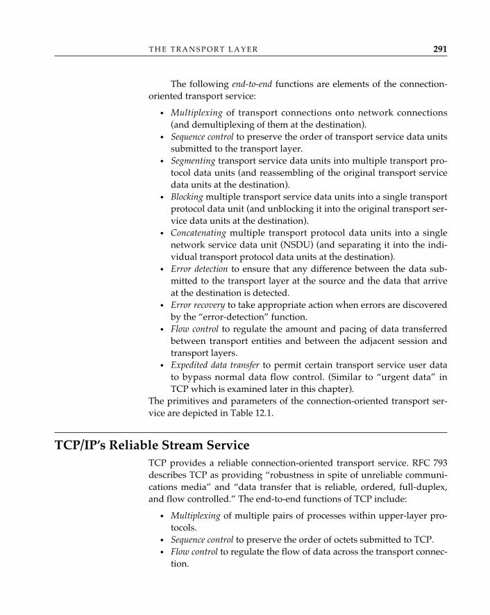
T H E T R A N S P O R T L A Y E R 291
The following end-to-end functions are elements of the connection-oriented transport service:
• Multiplexing of transport connections onto network connections(and demultiplexing of them at the destination).
• Sequence control to preserve the order of transport service data unitssubmitted to the transport layer.
• Segmenting transport service data units into multiple transport pro-tocol data units (and reassembling of the original transport servicedata units at the destination).
• Blocking multiple transport service data units into a single transportprotocol data unit (and unblocking it into the original transport ser-vice data units at the destination).
• Concatenating multiple transport protocol data units into a singlenetwork service data unit (NSDU) (and separating it into the indi-vidual transport protocol data units at the destination).
• Error detection to ensure that any difference between the data sub-mitted to the transport layer at the source and the data that arriveat the destination is detected.
• Error recovery to take appropriate action when errors are discoveredby the “error-detection” function.
• Flow control to regulate the amount and pacing of data transferredbetween transport entities and between the adjacent session andtransport layers.
• Expedited data transfer to permit certain transport service user datato bypass normal data flow control. (Similar to “urgent data” inTCP which is examined later in this chapter).
The primitives and parameters of the connection-oriented transport ser-vice are depicted in Table 12.1.
TCP/IP’s Reliable Stream ServiceTCP provides a reliable connection-oriented transport service. RFC 793describes TCP as providing “robustness in spite of unreliable communi-cations media” and “data transfer that is reliable, ordered, full-duplex,and flow controlled.” The end-to-end functions of TCP include:
• Multiplexing of multiple pairs of processes within upper-layer pro-tocols.
• Sequence control to preserve the order of octets submitted to TCP.• Flow control to regulate the flow of data across the transport connec-
tion.
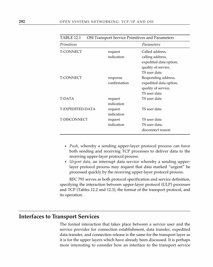
O P E N S Y S T E M S N E T W O R K I N G : T C P / I P A N D O S I292
• Push, whereby a sending upper-layer protocol process can forceboth sending and receiving TCP processes to deliver data to thereceiving upper-layer protocol process.
• Urgent data, an interrupt data service whereby a sending upper-layer protocol process may request that data marked “urgent” beprocessed quickly by the receiving upper-layer protocol process.
RFC 793 serves as both protocol specification and service definition,specifying the interaction between upper-layer protocol (ULP) processesand TCP (Tables 12.2 and 12.3), the format of the transport protocol, andits operation.
Interfaces to Transport ServicesThe formal interaction that takes place between a service user and theservice provider for connection establishment, data transfer, expediteddata transfer, and connection release is the same for the transport layer asit is for the upper layers which have already been discussed. It is perhapsmore interesting to consider how an interface to the transport service
TABLE 12.1 OSI Transport Service Primitives and Parameters
Primitives Parameters
T-CONNECT request Called address,indication calling address,
expedited data option,quality of service,TS user data
T-CONNECT response Responding address,confirmation expedited data option,
quality of service,TS user data
T-DATA request TS user dataindication
T-EXPEDITED-DATA request TS user dataindication
T-DISCONNECT request TS user dataindication TS user data,
disconnect reason
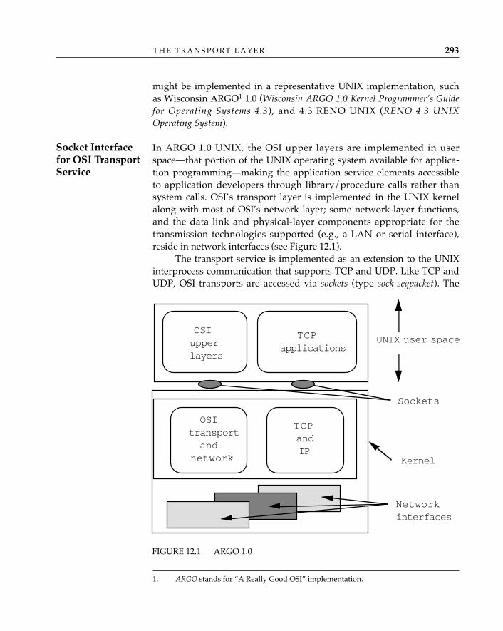
might be implemented in a representative UNIX implementation, suchas Wisconsin ARGO1 1.0 (Wisconsin ARGO 1.0 Kernel Programmer’s Guidefor Operating Systems 4.3), and 4.3 RENO UNIX (RENO 4.3 UNIXOperating System).
In ARGO 1.0 UNIX, the OSI upper layers are implemented in userspace—that portion of the UNIX operating system available for applica-tion programming—making the application service elements accessibleto application developers through library/procedure calls rather thansystem calls. OSI’s transport layer is implemented in the UNIX kernelalong with most of OSI’s network layer; some network-layer functions,and the data link and physical-layer components appropriate for thetransmission technologies supported (e.g., a LAN or serial interface),reside in network interfaces (see Figure 12.1).
The transport service is implemented as an extension to the UNIXinterprocess communication that supports TCP and UDP. Like TCP andUDP, OSI transports are accessed via sockets (type sock-seqpacket). The
T H E T R A N S P O R T L A Y E R 293
Socket Interfacefor OSI TransportService
1. ARGO stands for “A Really Good OSI” implementation.
FIGURE 12.1 ARGO 1.0
OSIupperlayers
TCPapplications
UNIX user space
Sockets
OSItransportand
network
TCPandIP
Kernel
Networkinterfaces
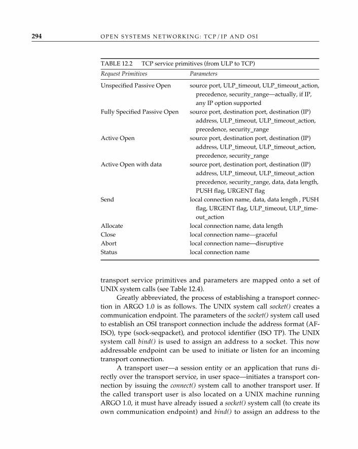
O P E N S Y S T E M S N E T W O R K I N G : T C P / I P A N D O S I294
transport service primitives and parameters are mapped onto a set ofUNIX system calls (see Table 12.4).
Greatly abbreviated, the process of establishing a transport connec-tion in ARGO 1.0 is as follows. The UNIX system call socket() creates acommunication endpoint. The parameters of the socket() system call usedto establish an OSI transport connection include the address format (AF-ISO), type (sock-seqpacket), and protocol identifier (ISO TP). The UNIXsystem call bind() is used to assign an address to a socket. This nowaddressable endpoint can be used to initiate or listen for an incomingtransport connection.
A transport user—a session entity or an application that runs di-rectly over the transport service, in user space—initiates a transport con-nection by issuing the connect() system call to another transport user. Ifthe called transport user is also located on a UNIX machine runningARGO 1.0, it must have already issued a socket() system call (to create itsown communication endpoint) and bind() to assign an address to the
TABLE 12.2 TCP service primitives (from ULP to TCP)
Request Primitives Parameters
Unspecified Passive Open source port, ULP_timeout, ULP_timeout_action,precedence, security_range—actually, if IP, any IP option supported
Fully Specified Passive Open source port, destination port, destination (IP) address, ULP_timeout, ULP_timeout_action, precedence, security_range
Active Open source port, destination port, destination (IP) address, ULP_timeout, ULP_timeout_action, precedence, security_range
Active Open with data source port, destination port, destination (IP) address, ULP_timeout, ULP_timeout_action precedence, security_range, data, data length, PUSH flag, URGENT flag
Send local connection name, data, data length , PUSH flag, URGENT flag, ULP_timeout, ULP_time-out_action
Allocate local connection name, data lengthClose local connection name—gracefulAbort local connection name—disruptiveStatus local connection name
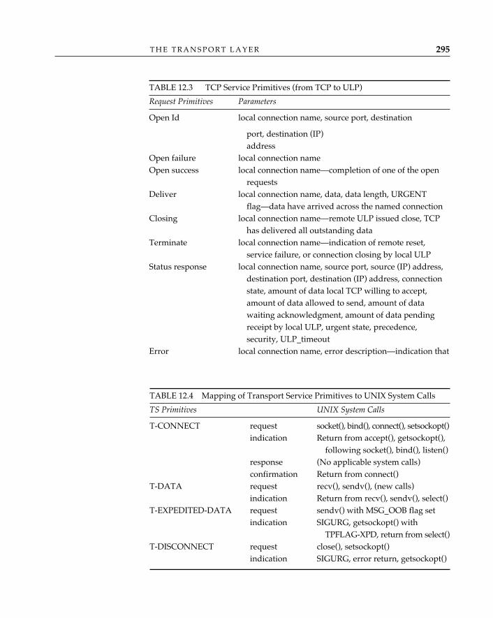
T H E T R A N S P O R T L A Y E R 295
TABLE 12.3 TCP Service Primitives (from TCP to ULP)
Request Primitives Parameters
Open Id local connection name, source port, destination
port, destination (IP) address
Open failure local connection nameOpen success local connection name—completion of one of the open
requestsDeliver local connection name, data, data length, URGENT
flag—data have arrived across the named connectionClosing local connection name—remote ULP issued close, TCP
has delivered all outstanding dataTerminate local connection name—indication of remote reset,
service failure, or connection closing by local ULPStatus response local connection name, source port, source (IP) address,
destination port, destination (IP) address, connection state, amount of data local TCP willing to accept, amount of data allowed to send, amount of data waiting acknowledgment, amount of data pending receipt by local ULP, urgent state, precedence, security, ULP_timeout
Error local connection name, error description—indication that
TABLE 12.4 Mapping of Transport Service Primitives to UNIX System Calls
TS Primitives UNIX System Calls
T-CONNECT request socket(), bind(), connect(), setsockopt()indication Return from accept(), getsockopt(),
following socket(), bind(), listen()response (No applicable system calls)confirmation Return from connect()
T-DATA request recv(), sendv(), (new calls)indication Return from recv(), sendv(), select()
T-EXPEDITED-DATA request sendv() with MSG_OOB flag setindication SIGURG, getsockopt() with
TPFLAG-XPD, return from select()T-DISCONNECT request close(), setsockopt()
indication SIGURG, error return, getsockopt()
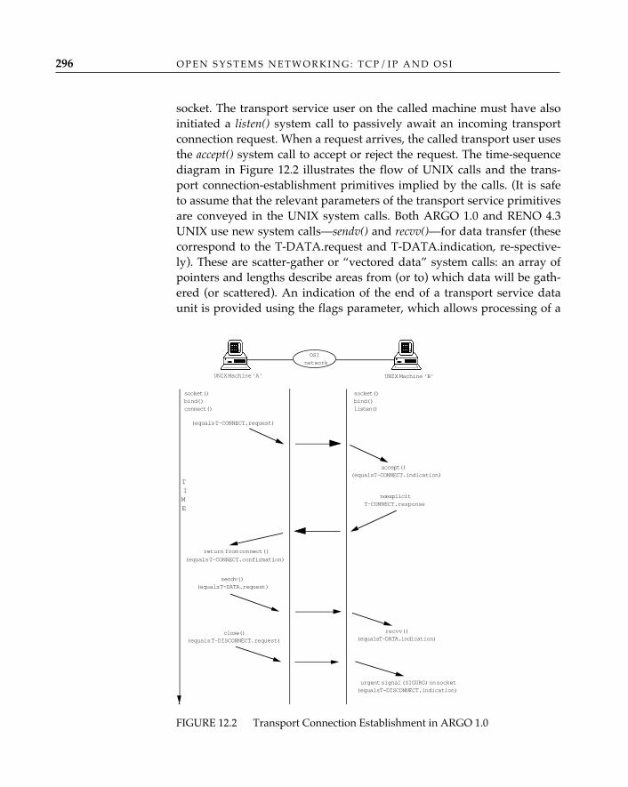
O P E N S Y S T E M S N E T W O R K I N G : T C P / I P A N D O S I296
socket. The transport service user on the called machine must have alsoinitiated a listen() system call to passively await an incoming transportconnection request. When a request arrives, the called transport user usesthe accept() system call to accept or reject the request. The time-sequencediagram in Figure 12.2 illustrates the flow of UNIX calls and the trans-port connection-establishment primitives implied by the calls. (It is safeto assume that the relevant parameters of the transport service primitivesare conveyed in the UNIX system calls. Both ARGO 1.0 and RENO 4.3UNIX use new system calls—sendv() and recvv()—for data transfer (thesecorrespond to the T-DATA.request and T-DATA.indication, re-spective-ly). These are scatter-gather or “vectored data” system calls: an array ofpointers and lengths describe areas from (or to) which data will be gath-ered (or scattered). An indication of the end of a transport service dataunit is provided using the flags parameter, which allows processing of a
FIGURE 12.2 Transport Connection Establishment in ARGO 1.0
socket()bind()connect()
(equals T-CONNECT.request)
socket()bind()listen()
(equals T-CONNECT.indication)accept()
no explicitT-CONNECT.response
return from connect()
(equals T-CONNECT.confirmation)
UNIX Machine 'A' UNIX Machine 'B'
OSInetwork
sendv()(equals T-DATA.request)
recvv()(equals T-DATA.indication)
close()(equals T-DISCONNECT.request)
urgent signal (SIGURG) on socket(equals T-DISCONNECT.indication)
TIME
transport service data unit to span multiple system calls. A sending userprocess distinguishes transport expedited data from normal data by set-ting the MSG_OOB flag in the sendv() call; the receiver is notified of thearrival of expedited data via a UNIX signal mechanism (SIGURG, inter-preted as an “urgent condition on the socket”). User processes initiatetransport connection release using the close() system call. An applicationprocess is notified of a peer transport user (or transport provider) initiat-ed release via an urgent condition on the socket (or via an error return onother primitives), whereupon the socket is closed.
Like sockets, the X/OPEN Transport Interface (XTI) offers a program-matic interface to OSI transport protocols. Specifically, the X/OPENTransport Interface allows transport users (user processes) to requesttransport classes 0, 2, and 4 over network connections and transport class4 over network datagrams. The X/OPEN Transport Interface supportstransport protocol class selection, expedited data, quality of service,orderly release, and variable-length transport addresses and supportsboth synchronous and asynchronous communication. With synchronouscommunication, the calling transport user attempts to connect and waitsfor an accept; similarly, a called transport user will wait and listen for anincoming transport connection (passive). With asynchronous communica-tion, the calling transport user attempts to connect and goes off to doother things until notified that the transport connection has been accept-ed (active); a transport user awaiting an incoming transport connectionmay listen as a background activity and attend to other operations.
Synchronous communication is the default mode of communica-tion for the t_connect() system call. The transport connection-establish-ment process is similar to the UNIX socket interface: a transport user cre-ates a transport endpoint using the t_open() system call, then binds atransport address to the endpoint using the t_bind() system call. Anactive open is invoked via the t_connect() system call, followed by a callto poll() with time-out value to await confirmation. A passive open isinvoked via the t_listen() system call. All active processes must create alistening endpoint; a separate responding endpoint is created for eachtransport connection. A listening transport user accepts an incomingtransport connection by invoking the t_accept() system call; to reject anincoming transport connection, a listening transport user returns a t_snd-dis() system call rather than the t_accept().
If the transport connection is accepted, the transport usersexchange data using the t_snd() and t_rcv() system calls. In the synchro-nous mode, a sending transport user waits if flow is constrained; in the
T H E T R A N S P O R T L A Y E R 297
The X/OPENTransportInterface
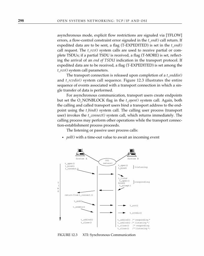
O P E N S Y S T E M S N E T W O R K I N G : T C P / I P A N D O S I298
asynchronous mode, explicit flow restrictions are signaled via [TFLOW]errors, a flow-control constraint error signaled in the t_snd() call return. Ifexpedited data are to be sent, a flag (T-EXPEDITED) is set in the t_snd()call request. The t_rcv() system calls are used to receive partial or com-plete TSDUs; if a partial TSDU is received, a flag (T-MORE) is set, reflect-ing the arrival of an end of TSDU indication in the transport protocol. Ifexpedited data are to be received, a flag (T-EXPEDITED) is set among thet_rcv() system call parameters.
The transport connection is released upon completion of a t_snddis()and t_rcvdis() system call sequence. Figure 12.3 illustrates the entiresequence of events associated with a transport connection in which a sin-gle transfer of data is performed.
For asynchronous communication, transport users create endpointsbut set the O_NONBLOCK flag in the t_open() system call. Again, boththe calling and called transport users bind a transport address to the end-point using the t–bind() system call. The calling user process (transportuser) invokes the t_connect() system call, which returns immediately. Thecalling process may perform other operations while the transport connec-tion-establishment process proceeds.
The listening or passive user process calls:
• poll() with a time-out value to await an incoming event
t_open()
t_connect()
t_open()
t_listen
t_accept(
return from t_connect()
System A System B
t_bind()t_bind(
t_snd()
t_rcv()t_snddis()
t_rcvdis()
}listening
t_open()bind() }responding
t_unbind()t_close()
t_unbind() /* responding *t_unbind() /* listening */t_close() /* responding *t_close() /* listening */
OSInetwork
TIME
FIGURE 12.3 XTI: Synchronous Communication
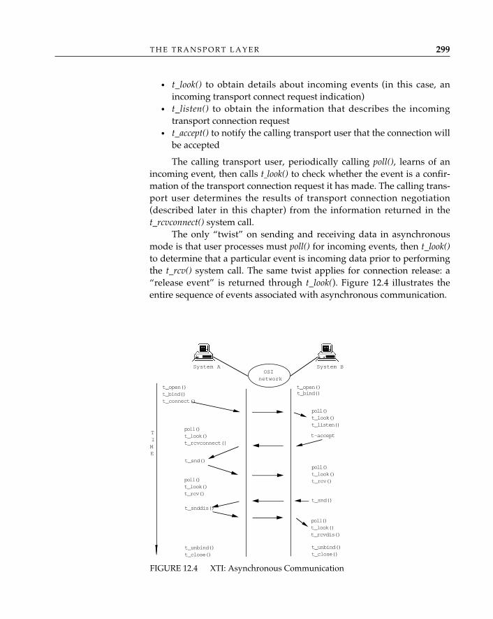
T H E T R A N S P O R T L A Y E R 299
• t_look() to obtain details about incoming events (in this case, anincoming transport connect request indication)
• t_listen() to obtain the information that describes the incomingtransport connection request
• t_accept() to notify the calling transport user that the connection willbe accepted
The calling transport user, periodically calling poll(), learns of anincoming event, then calls t–look() to check whether the event is a confir-mation of the transport connection request it has made. The calling trans-port user determines the results of transport connection negotiation(described later in this chapter) from the information returned in thet_rcvconnect() system call.
The only “twist” on sending and receiving data in asynchronousmode is that user processes must poll() for incoming events, then t_look()to determine that a particular event is incoming data prior to performingthe t_rcv() system call. The same twist applies for connection release: a“release event” is returned through t_look(). Figure 12.4 illustrates theentire sequence of events associated with asynchronous communication.
t_open()t_bind()t_connect()
t_open()
poll()t_look()t_listen()
t-acceptpoll()t_look()t_rcvconnect()
System A System B
t_bind()
t_snd()poll()t_look()t_rcv()
t_snddis()
poll()t_look()t_rcvdis()
t_unbind()t_close()
t_unbind()t_close()
poll()t_look()t_rcv()
t_snd()
OSInetwork
TIME
FIGURE 12.4 XTI: Asynchronous Communication
O P E N S Y S T E M S N E T W O R K I N G : T C P / I P A N D O S I300
Transport AddressingIn the set of UNIX system calls used to establish interprocess communi-cation between TCP/IP applicatons, a set of Internet port numbers is usedto differentiate users of the stream and datagram services provided bythe transport layers. There are, for example, well-known or “assigned”numbers for the Internet standard applications servers (e.g., FTP, SMTP,SNMP, TELNET). For OSI-based interprocess communication in UNIX,ARGO 1.0 uses a separate address space, transport service access point iden-tifiers,2 to name the interface between the transport service users and thetransport entities in the kernel. Like ports, transport service access pointidentifiers are a particularly important set of names, since they are oftenvisible to program interfaces such as the UNIX socket.
The parameters of the socket() system call used to establish an OSItransport connection include the address family/format (AF-ISO), type(sock-seqpacket), and protocol identifier (ISO TP). The transport serviceaccess point identifier assigned to a socket using the bind() system callusually takes the following form:
struct sockaddr_iso {short siso_family; /* address family is iso */u_short siso_tsuffix; /* the TSAP identifier */struct iso_addr siso_addr; /* the NSAP address */char siso_zero[2]; /* unused */
}
The transport service access point address is represented as the con-catenation of the network service access point address and a transportselector. The C programming-language data structure and the data struc-ture used to assign an Internet port/address when establishing a socket(type stream) are very similar; e.g.:
struct sockaddr_in {short sin_family; /* address family is internet */u_short sin_port; /* the internet port */struct in_addr sin_addr; /* the IP address, a.b.c.d */char sin_zero[8]; /* unused */
}
In TCP/IP, ports identify upper-level protocol entities or processes,
2. The full address of a transport service access point consists of a network serviceaccess point address and a transport service access point identifier. The term “transport ser-vice access point address” refers to this full address; where only the identifier part (some-times called a “transport selector”) is meant, the term “transport service access point identi-fier” or simply “transport identifier” will be used.
and pairs of endpoints identify TCP connections. Specifically, the pair {IPaddress, port number} roughly corresponds to the OSI transport serviceaccess point address, which is the pair {network service access pointaddress, transport selector}, and two of these {IP address, port number}pairs uniquely identify a TCP connection. Internet port number assign-ment follows a client/server paradigm. A server process binds to a well-known port number and listens at {server-IP-address, well known-tcp-port} for connection requests from any source; i.e., from {any-IP-address,any-port}. A client process binds to {client-tcp-port, client-IP-address},where client-tcp-port is dynamically allocated from unused ports on theclient’s system. When a client process initially connects to a serverprocess, the endpoints of the transport connection are {client-IP-address,client-tcp-port} and {server-IP-address, well known-tcp-port}, but whenthe server accepts an incoming request, it creates a second socket andbinds the incoming call to this new socket; the resulting endpoints of thetransport connection are {client-IP-address, client-tcp-port} and {server-IP-address, server-tcp-port}. Once the server process has mapped thetransport connection onto this new pair of endpoints, it continues to lis-ten at {server-IP-address, server-tcp-port} for requests from any source;i.e., from {any-IP-address, any-port}.
Internet port numbers are always 16 bits. OSI allows for variable-lengthtransport service access point identifiers, up to a maximum length of 64octets. ARGO 1.0 accommodates the assignment of extended transportidentifiers through the use of the getsockopt() or setsockopt() system callsfollowing the call to bind(). Another difference between OSI transportservice access point identifiers and Internet port numbers is that, gener-ally speaking, a set of Internet port numbers are globally and uniquelyassigned to represent a well-known application; transport service accesspoint identifiers are frequently derived from the presentation addressattribute of an application entity title (see Chapters 5, 7, and 11).
Five Classes of OSI Transport ProtocolThe Connection Oriented Transport Protocol Specification (ISO/IEC 8073:1986) defines five classes of procedures for the connection-oriented OSItransport protocol. The transmission control protocol (TCP), on the otherhand, has no concept of “class”; it simply defines one standard way inwhich to provide a connection-oriented transport service.
The answer to the question “why five classes of transport protocol
T H E T R A N S P O R T L A Y E R 301
A Comparison ofInternet Portsand OSI TSAPAs
in OSI?” lies not in the transport layer but in the network layer. If one’smodel of the world has end-user equipment (hosts) attached to specificindividual networks, then one is likely to design a separate transportprotocol for each individual network, optimized for the particular char-acteristics of that network. If one’s model of the world has end-userequipment attached to a global internet, consisting of an arbitrary num-ber of interconnected individual networks, then one is likely to design asingle transport protocol that provides an end-to-end service withrespect to the internet as a whole and makes few (if any) assumptionsabout the characteristics of individual networks (which, as part of theinternet, are not individually visible to the transport protocol). Each ofthe OSI transport protocol classes 0 through 3 is intended to be used witha particular type of connection-oriented network, according to the proba-bility of signaled and unsignaled errors on that network. Class 4, likeTCP, is intended to be used in internets and is not defined with respect toany particular network type.
Class 0 is designed to have “minimum functionality.” It provides onlythe functions necessary to establish a transport connection, transfer data(well, it can segment transport service data units), and report protocolerrors. Class 0 relies on the underlying network connection to provide allof the end-to-end capabilities of the transport layer, including sequenc-ing, flow control, and error detection. It was designed with the expecta-tion that the underlying network connection would provide a virtuallyerror-free data-transfer service; for example, in those subnetworks inwhich a protocol such as CCITT X.25-1984 is used. Class 0 does not pro-vide multiplexing capabilities, and it is so resolutely simple that it doesnot even have its own disconnection procedures: when the underlyingnetwork connection goes away, transport class 0 goes with it.
Class 0 adds no value whatsoever to the underlying networkservice, which is just the way some network service providers
like it. (“Our network service is absolutely splendid. How could you end userspossibly imagine that any further work is necessary on your part to obtain a reli-able end-to-end connection?”) Class 0 is equivalent to the transport protocoldefined for the CCITT Teletex service; it persists because it has been written intothe CCITT X.400-series recommendations for message handling systems as therequired protocol class for connection to public network messaging systems.3
✧AHA✧
O P E N S Y S T E M S N E T W O R K I N G : T C P / I P A N D O S I302
Class 0: TheSimple Class
3. The CCITT X-series recommendations differ from ISO standards in that each servicedefinition identifies precisely the protocol that must be used to provide the service; e.g., the
Class 0 does have one redeeming feature: it is used to create an OSItransport service on TCP/IP networks, enabling OSI applications to runover TP/IP. RFC 1006, ISO Transport Services on Top of the TCP, specifies awidely used convention for operating OSI applications over TCP/IP net-works. TCP, complemented by a simple 4-octet packetization protocol,provides the essence of the connection-oriented OSI network serviceacross TCP/IP networks (in fact, it does so better than the OSI connec-tion-oriented network protocol, X.25), and OSI transport protocol class 0provides two service features—the transfer of transport addresses andtransport service data unit delimiting—to complete the OSI transportservice.
Transport class 1 is a small improvement over class 0, providing error re-covery following a failure signaled by the network service, expediteddata, and an explicit transport connection release (distinct from networkconnection release). Class 1 could almost be called “the apologist’s trans-port protocol.” It recognizes that no connection-oriented network in thereal world is truly perfect. Where class 0 says, “Trust me, the network willnever do anything bad,” class 1 says, “The network will never do any-thing bad without telling me about it, and if it does, I’ll take care of it.”
Several error recovery procedures are included in class 1:
• Retention until acknowledgment: Following a signaled failure, copiesof outstanding transport protocol data units are retained untilreceipt of an indication that the remote transport entity is alive, atwhich time resynchronization procedures are invoked.
• Reassignment after failure: If the underlying network connection sig-nals a Disconnect, class 1 can map the existing transport connectiononto a new network connection.
• Resynchronization: Following a recoverable failure signaled by thenetwork connection (e.g., a reset; see Chapter 13) or a reassignmentafter failure, both transport entities retransmit unacknowledgedtransport protocol data units and resynchronize the data stream.
Class 1 can recover only from errors explicitly signaled by the net-work service provider. Errors not detected and reported by the networkservice provider will also go undetected by the transport protocol.
T H E T R A N S P O R T L A Y E R 303
Class 1: The BasicError RecoveryClass
CCITT Recommendation T.70 for teletex terminals must be used to provide the OSI trans-port service when connecting to a public MHS. ISO service-definition standards describeonly the features of a service, implying that a number of protocols might be used to pro-vide that service.
The experts who introduced class 0 were quite pleased about having iden-tified a minimally functional, low-overhead transport protocol until theyrealized that they had failed to consider one very important aspect of sub-scriber access to an X.25 public data network: for economy, subscribersoften multiplex data streams from more than one piece of data terminalequipment over a single network connection provided by an X.25 networkto maximize use of the throughput available over that network connection.The most obvious way to correct this oversight would have been to extendthe functionality of class 0. Class 0 “protectionists,” while acknowledgingthat multiplexing was useful, argued for stability and consistency betweenthe ISO transport protocol standard and CCITT Recommendation T.70, thetransport protocol for teletex terminals. (It should also be noted that thefolks who work for carrier networks were not as keenly interested in mul-tiplexing as were end users.) Thus was born Class 2.
The following functions are present in class 2:
• Reference numbers enable two communicating transport entities todistinguish the transport protocol data units associated with onetransport connection from those associated with a different trans-port connection.
• Explicit flow control, when selected, allows the transport entities toregulate the amount and pacing of data transferred between them.
• Expedited data transfer permits the transmission of up to 16 octets ofuser data that are not subject to normal flow-control procedures.
• Extended transport protocol data unit numbering, when selected, allowstransport entities to use a larger sequence number space (31-bit,rather than the normal 7-bit) for transport protocol data unit num-bering and acknowledgments. This increases the number of trans-port protocol data units that a sender can transmit (the “send win-dow”) before it must wait for explicit acknowledgment of receptionby the receiver. Normally, the use of a larger window increasesthroughput. Increasing the size of the sequence number space is alsonecessary to eliminate the possibility of sequence numbers “wrap-ping”; for example, if the sequence space were {1 . . . 10}, and a win-dow of 15 were allowed, a sender could transmit packets in se-quence {1 . . . 10, 1, 2, 3, 4, 5}. Receiving this sequence of packets, thereceiver would be unable to determine whether the second transportprotocol data unit received containing the sequence number 1 was aduplicate of a transport protocol data unit received earlier withsequence number 1 or a new transport protocol data unit with thesame “wrapped” sequence number.
O P E N S Y S T E M S N E T W O R K I N G : T C P / I P A N D O S I304
Class 2: TheMultiplexingClass
Curiously, class 2 adds only those functions necessary to supportmultiplexing; in particular, the error-detection capabilities of class 1 aremissing from class 2.4
When the work on OSI transport-layer standards began in the late 1970s,most of the people involved approached the job with a particular type ofnetwork in mind—an X.25 packet-switching network, for example, or anX.21 circuit-switching network—each of which suggested differentdesign criteria for a corresponding transport protocol. Lacking the inter-networking perspective of the people who designed TCP/IP, the ISOexperts proceeded to deal with each of the available network services ona case-by-case basis, accommodating differences in reliability and fea-tures not by designing a single, highly resilient, and competent transportprotocol but by introducing one after another.
So it came to pass that yet another group of experts studied theexisting set of transport protocols and—feeling either remorse, concern,or both—decided that at least one transport protocol should combine allof the features of the existing transport protocols. Class 3 represents theunion of the functions and capabilities of classes 0 through 2 and thensome; the transport protocol standard describes class 3 as having “. . . thecharacteristics of Class 2 plus the ability to recover from network discon-nect or reset.” Specifically, transport protocol class 3 provides the multi-plexing functions of class 2 plus the error recovery functions of class 1.
Implicit in the design of the first four OSI transport protocol classes is theassumption that any errors that might occur in the transfer of data acrossa network connection will be detected by the network service providerand signaled to the transport entities. Prior to the introduction of class 4,transport protocol design was based on a “network-centric” view of theworld: like the dial tone in the telephone system, the OSI network servicewould in all configurations be provided by one or more common carri-ers, and service uniformity and homogeneity would be the rule ratherthan the exception. Further, compelling political and economic argu-ments existed that made perpetuating the notion that the bulk of end-to-end functionality could be provided at the network layer a standardsimperative.
T H E T R A N S P O R T L A Y E R 305
4. Many implementers who are initially appalled by the fact that there are five distinctclasses of transport protocol in OSI comfort themselves with the assumption that at leastthey will be able to implement them by incrementally adding functions to lower classes tocreate successively higher ones. They are truly aghast when they discover that this is notthe case.
Class 3: The ErrorRecovery andMultiplexingClass
Class 4: TheError-Detectionand RecoveryClass
Technically speaking, the “network is everything” school of thoughtviews the service provided from network entry to network exit as havingend-to-end significance. In implementation and practice, however, the net-working protocols and interworking among those protocols in fact pro-vide only edge-to-edge significance. As will be seen in Chapter 13, the pro-vision of network services, like all human endeavor, is fallible, and vari-ability exists. This is particularly true when multiple providers anddiverse technologies are involved in the process. Humans tolerate vari-ability in the voice network because they intuitively apply error-detec-tion and recovery mechanisms; computers lack intuition, so the protocolsthey use to transfer data must be designed to recognize a variety of fail-ures and recover from them. Until the introduction of transport protocolclass 4 (generally referred to as “TP4”), many of the necessary reliabilityfunctions were absent.
Several years prior to the OSI transport standardization effort,research in the United States questioned the premise that reliability couldbe assured by establishing uniformity across all networking services.Practical experience gained in the implementation and use of researchnetworks such as the U.S. Department of Defense Advanced ResearchProjects Agency (DARPA) Internet Research Project (RFC 791), theLivermore Interactive Network Communication System (LINCS; Watson1982), and the Ethernet-oriented architecture developed at the Xerox PaloAlto Research Center (Xerox Corporation 1981) demonstrated the bene-fits of incorporating all end-to-end reliability functions into a single pro-tocol that operated in host computers (end systems) and relying on thenetwork to perform only the functions essential to the forwarding anddelivery of information from source to destination. Since the transportlayer takes nothing for granted in this model, the variability of servicequality among interconnected networks becomes a non-issue. An entirelydifferent axiom was espoused: “Sadly, it is a fact of networking life that bitsget smashed, octets and packets arrive out of order, some arrive twice, and somedo not arrive at all.” Host protocols must therefore be prepared to dealwith these problems. From this “host-centric” school of thought, trans-port protocols such as TCP and OSI transport protocol class 4 emerged.
The OSI transport protocol standard describes class 4 as having “. . .the functionality of class 3 plus the ability to detect and recover from lost,duplicated, or out of sequence transport protocol data units.” This issomewhat misleading, since the mechanisms to provide reliability inclass 4 differ substantially from those in class 3. It is more accurate to saythat transport protocol class 4 provides the multiplexing functions ofclass 2 and explicit flow control, plus error detection and error recovery
O P E N S Y S T E M S N E T W O R K I N G : T C P / I P A N D O S I306
T H E T R A N S P O R T L A Y E R 307
based on the “positive acknowledgment and retransmission” paradigmof TCP. The functions of TP4 include those of class 2 plus:
• A checksum computed on the transport header and user data. A 16-bit arithmetic checksum based on Fletcher (1982) is computed todetect bit-level errors in the data stream.
• Resequencing, which enables a receiver to determine when transportprotocol data units have arrived out of order and provides a meansof correctly ordering the octet stream before passing it up to thetransport service user.
• Inactivity control, which enables a transport connection to survivethe (temporary) unsignaled loss of network layer connectivity.
• Splitting and recombining, which enable a transport connection totransfer data simultaneously over multiple network connections toincrease throughput or provide resiliency from single network con-nection failure.
• Detection and recovery of lost and duplicate transport protocol dataunits.
TP4 is genetically closer to TCP, Xerox’s RTP, and their proprietarynetworking relatives (e.g., the reliable transports in Digital EquipmentCorporation’s DECnet and Burroughs Network Architecture) than the“Tinkertoy” classes that do not provide an actual end-to-end transport ser-vice. Later in this chapter we will demonstrate just how similar TCP andTP4 are.
Having five transport protocols to choose from is clearly a problem forboth implementers and users. The way in which the OSI standard de-scribes how to choose which of the transport protocols to use in a givenconfiguration only adds to the confusion. So how do you choose one? Thetransport protocol standard recommends that a transport protocol class bechosen to support a given transport connection based on the type of net-work connection available at the time of connection establishment and thequality of service requested by the transport service user. Since no meaning-ful guidelines for the specification or interpretation of quality of serviceparameters have ever been produced for OSI, class selection relies almostentirely on the underlying network type. The standard identifies threetypes of network connection:
1. Type A: a network connection with an acceptable residual error rateand an acceptable rate of signaled errors.
2. Type B: a network connection with an acceptable residual error ratebut an unacceptable rate of signaled errors.
How Do YouChoose the RightOne?
3. Type C: a network connection with an unacceptable residual errorrate.5
This, of course, begs the question of how the service quality of net-work connections can be known in advance. Good question, and also oneleft unanswered by the standard. Like Pilate, the transport protocol stan-dard washes its hands of the responsibility, saying only that “It isassumed that each transport entity is aware of the quality of service pro-vided by particular network connections . . . .” An immediate reaction byany right-thinking individual is that this is a joke. It is impossible toimagine how any individual host could know a priori the type and char-acteristics of all the network connections that might be available to con-nect to all the host machines in a small, private network, much less aglobal OSI network! The transport standard’s assumption of this naturebelies the notion of typing altogether, since it is meaningful only if ser-vice uniformity is assumed across every possible set of interconnectednetworks. (Such uniformity cannot be guaranteed even in the globalvoice network, which is far more homogenous than any conceivableglobal data network.)
In fact, the typing of network connections was merely a conve-nient premise for the existence of multiple transport protocol
classes, which served a different purpose altogether. The political realities of thetime demanded that each of several existing public network services be character-ized within OSI as having at least the potential to be the cornerstone of the per-vasive worldwide network, connecting all hosts everywhere. Each of these must,perforce, have its own specially optimized transport protocol. But since compro-mise and consensus are supposed to be the essence of standardization, it wouldhardly do to have several separate incompatible standards. The solution was totalk not about specific existing networks but about “types” of networks, withwhich different “classes” of a single protocol standard could be associated.Achieving this “compromise” made some of the standards developers veryhappy, while creating a legacy of confusion and incompatibility for OSI imple-menters and users. Thankfully, at least one of the five classes was based on thepractical realization that all of these subnetworks—along with LANs, MANs,spaghetti-nets, and future-nets—would someday be interconnected.
✧AHA✧
O P E N S Y S T E M S N E T W O R K I N G : T C P / I P A N D O S I308
5. In the early stages of OSI transport protocol development, only the connection-ori-ented network service existed. The connectionless network service and a corresponding ad-dendum to the transport protocol describing how to operate transport protocol class 4 wereintroduced later. For reasons unknown, networks that offered a connectionless service wereconsidered to offer service functionally equivalent to type-C NCs.
T H E T R A N S P O R T L A Y E R 309
The whole notion of typing network connections was myopic, ill-advised,and ultimately destructive. Ironically, by insisting on a menu of “tailor-made”transport protocols, the “network-centric” individuals who had compellingpolitical and economic motivations to promote a uniform network service accom-plished just the opposite, exposing how diverse even publicly provided networkservices were!
ConformanceWhat happens when you have more than one choice of protocol? In thecase of OSI transport, every delegation, liaison body, even individualswithin delegations championed a different protocol. It was popular, forexample, but not mandatory, to champion the protocol that one’s delega-tion introduced. The phrase “spirit of compromise” was at first eagerlyembraced and subsequently worn extremely thin during the joint ISO/CCITT meetings at which the issue of determining the conformance clausefor the OSI transport protocol was discussed.
Combinations were popular, especially if the combination includedthe protocol one championed. In fact, once combinations were recog-nized as instrumental in proceeding, the joint committees quickly agreedto eliminate two of the possible combinations (support none and supportall). Eventually, it became clear that under no circumstances would thenetwork-centric community agree to abandon support for TP0, and hellwould freeze over before the host-centric community would consideranything other than TP4 sufficient for its purposes. The resultant confor-mance clause is a travesty, a status quo ante openum: To claim confor-mance to the standard, you must implement class 0 or class 2 or both.Further, if you implement class 1, you must implement class 0. If youimplement class 3 or class 4, you must implement class 2. Confused?There’s more. You can operate only class 4 over the connectionless net-work service.
The solution? If you are implementing OSI transport for usewith an internetworking protocol (such as CLNP), it’s easy—
class 4 is the only class that will work at all over a connectionless network ser-vice. To cover all possible cases, including those in which your system will oper-ate directly over a connection-oriented network (such as an X.25 network) withno internetwork protocol, implement classes 0, 2, and 4. It’s no big deal addingclasses 0 and 2, since both are no-brainers. Notwithstanding what must have
✧AHA✧
O P E N S Y S T E M S N E T W O R K I N G : T C P / I P A N D O S I310
seemed like good arguments in their favor at the time, classes 1 and 3 have nomodern constituency and can safely be ignored. If you are an end user, and youcare about reliability, you should insist on class 4; tell your vendors “No discus-sion—just do it.”
Comparing TP4 to TCPA 1985 study performed jointly by the U.S. Defense CommunicationsAgency and the National Academy of Sciences (National Academy ofSciences Report 1985) concludes that TCP and TP4 are functionallyequivalent and provide essentially similar services. Table 12.5 comparesthe functions provided by the two protocols.
Table 12.5 Comparison of TP4 and TCP Functions
Function TCP TP4
Data transfer Streams BlocksFlow control Octets SegmentsError detection6 Checksum ChecksumError correction Retransmission RetransmissionAddressing 16-bit ports Variable TSAPAInterrupt service Urgent data Expedited dataSecurity Not available Variable in TPPrecedence Not available 16 bits in TPConnection termination Graceful Nongraceful
6. The TCP and TP4 checksum functions are both intended to detect errors that may beintroduced into the data stream between two transport users, but they do not operate in thesame way. The TP4 checksum computation is carried out on the transport packet (headerand user data) only, and it may be disabled (by explicitly selecting the “nonuse of check-sum” option during connection establishment; the default is to use checksums). The TCPchecksum is carried out on the combination of the transport packet (header and user data)and a prepended “pseudoheader” consisting of the source and destination IP addresses, theIP PROTO field, and the TCP segment length, and it may not be disabled. The TP4 check-sum is also slightly more complicated (both to generate at the sender and to verify at thereceiver) than the TCP checksum, although the additional complexity does not make TP4significantly more resistant to undetected errors than TCP. An excellent discussion of howto efficiently implement the TP4 checksum is contained in Sklower (1989); a similar analysisfor TCP may be found in RFC 1071, Clark (1989), and RFC 1141.
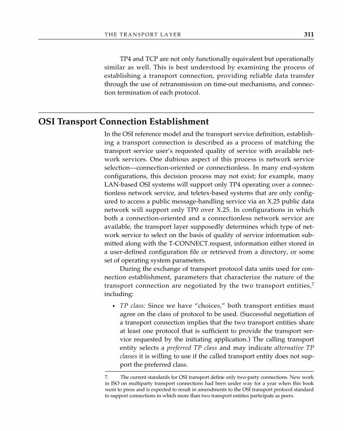
T H E T R A N S P O R T L A Y E R 311
TP4 and TCP are not only functionally equivalent but operationallysimilar as well. This is best understood by examining the process ofestablishing a transport connection, providing reliable data transferthrough the use of retransmission on time-out mechanisms, and connec-tion termination of each protocol.
OSI Transport Connection EstablishmentIn the OSI reference model and the transport service definition, establish-ing a transport connection is described as a process of matching thetransport service user’s requested quality of service with available net-work services. One dubious aspect of this process is network serviceselection—connection-oriented or connectionless. In many end-systemconfigurations, this decision process may not exist; for example, manyLAN-based OSI systems will support only TP4 operating over a connec-tionless network service, and teletex-based systems that are only config-ured to access a public message-handling service via an X.25 public datanetwork will support only TP0 over X.25. In configurations in whichboth a connection-oriented and a connectionless network service areavailable, the transport layer supposedly determines which type of net-work service to select on the basis of quality of service information sub-mitted along with the T-CONNECT.request, information either stored ina user-defined configuration file or retrieved from a directory, or someset of operating system parameters.
During the exchange of transport protocol data units used for con-nection establishment, parameters that characterize the nature of thetransport connection are negotiated by the two transport entities,7
including:
• TP class: Since we have “choices,” both transport entities mustagree on the class of protocol to be used. (Successful negotiation ofa transport connection implies that the two transport entities shareat least one protocol that is sufficient to provide the transport ser-vice requested by the initiating application.) The calling transportentity selects a preferred TP class and may indicate alternative TPclasses it is willing to use if the called transport entity does not sup-port the preferred class.
7. The current standards for OSI transport define only two-party connections. New workin ISO on multiparty transport connections had been under way for a year when this bookwent to press and is expected to result in amendments to the OSI transport protocol standardto support connections in which more than two transport entities participate as peers.
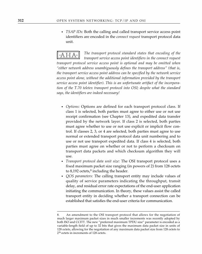
• TSAP IDs: Both the calling and called transport service access pointidentifiers are encoded in the connect request transport protocol dataunit.
The transport protocol standard states that encoding of thetransport service access point identifiers in the connect request
transport protocol service access point is optional and may be omitted when“either network address unambiguously defines the transport address” (that is,the transport service access point address can be specified by the network serviceaccess point alone, without the additional information provided by the transportservice access point identifier). This is an unfortunate artifact of the incorpora-tion of the T.70 teletex transport protocol into OSI; despite what the standardsays, the identifiers are indeed necessary!
• Options: Options are defined for each transport protocol class. Ifclass 1 is selected, both parties must agree to either use or not usereceipt confirmation (see Chapter 13), and expedited data transferprovided by the network layer. If class 2 is selected, both partiesmust agree whether to use or not use explicit or implicit flow con-trol. If classes 2, 3, or 4 are selected, both parties must agree to usenormal or extended transport protocol data unit numbering and touse or not use transport expedited data. If class 4 is selected, bothparties must agree on whether or not to perform a checksum ontransport data packets and which checksum algorithm they willuse.
• Transport protocol data unit size: The OSI transport protocol uses afixed maximum packet size ranging (in powers of 2) from 128 octetsto 8,192 octets,8 including the header.
• QOS parameters: The calling transport entity may include values ofquality of service parameters indicating the throughput, transitdelay, and residual error rate expectations of the end-user applicationinitiating the communication. In theory, these values assist the calledtransport entity in deciding whether a transport connection can beestablished that satisfies the end-user criteria for communication.
✧AHA✧
O P E N S Y S T E M S N E T W O R K I N G : T C P / I P A N D O S I312
8. An amendment to the OSI transport protocol that allows for the negotiation ofmuch larger maximum packet sizes in much smaller increments was recently adopted byboth ISO and CCITT. The new ”preferred maximum TPDU size” parameter is encoded as avariable-length field of up to 32 bits that gives the maximum data packet size in units of128 octets, allowing for the negotiation of any maximum data packet size from 128 octets to236 octets in increments of 128 octets.
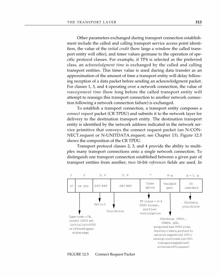
T H E T R A N S P O R T L A Y E R 313
Other parameters exchanged during transport connection establish-ment include the called and calling transport service access point identi-fiers, the value of the initial credit (how large a window the called trans-port entity will offer), and timer values germane to the operation of spe-cific protocol classes. For example, if TP4 is selected as the preferredclass, an acknowledgment time is exchanged by the called and callingtransport entities. This timer value is used during data transfer as anapproximation of the amount of time a transport entity will delay follow-ing reception of a data packet before sending an acknowledgment packet.For classes 1, 3, and 4 operating over a network connection, the value ofreassignment time (how long before the called transport entity willattempt to reassign this transport connection to another network connec-tion following a network connection failure) is exchanged.
To establish a transport connection, a transport entity composes aconnect request packet (CR TPDU) and submits it to the network layer fordelivery to the destination transport entity. The destination transportentity is identified by the network address indicated in the network ser-vice primitive that conveys the connect request packet (an N-CON-NECT.request or N-UNITDATA.request; see Chapter 13). Figure 12.5shows the composition of the CR TPDU.
Transport protocol classes 2, 3, and 4 provide the ability to multi-plex many transport connections onto a single network connection. Todistinguish one transport connection established between a given pair oftransport entities from another, two 16-bit references fields are used. In
FIGURE 12.5 Connect Request Packet
LI CR CDT DST-REF
Type code = CR,credit (CDT) setinitially to 0000or offered upperwidow edge
1 2 3, 4 5, 6 7
SRC REF
Set to 0
Variablepart
8–p
Classoption
Your choice
TP class = 0–4TPDU format,and flow-
control option
Checksum (TP4),TSAPA, QOS,
proposed max TPDU size,version, timers, protectionetwork expedited (TP1)?receipt confirmation(TP1
transport expedited?alternate TP classes?
TSuser data
p + 1, q
32 octets,your choice
-
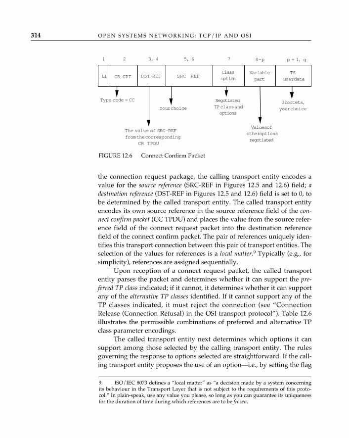
O P E N S Y S T E M S N E T W O R K I N G : T C P / I P A N D O S I314
the connection request package, the calling transport entity encodes avalue for the source reference (SRC-REF in Figures 12.5 and 12.6) field; adestination reference (DST-REF in Figures 12.5 and 12.6) field is set to 0, tobe determined by the called transport entity. The called transport entityencodes its own source reference in the source reference field of the con-nect confirm packet (CC TPDU) and places the value from the source refer-ence field of the connect request packet into the destination referencefield of the connect confirm packet. The pair of references uniquely iden-tifies this transport connection between this pair of transport entities. Theselection of the values for references is a local matter.9 Typically (e.g., forsimplicity), references are assigned sequentially.
Upon reception of a connect request packet, the called transportentity parses the packet and determines whether it can support the pre-ferred TP class indicated; if it cannot, it determines whether it can supportany of the alternative TP classes identified. If it cannot support any of theTP classes indicated, it must reject the connection (see “ConnectionRelease (Connection Refusal) in the OSI transport protocol”). Table 12.6illustrates the permissible combinations of preferred and alternative TPclass parameter encodings.
The called transport entity next determines which options it cansupport among those selected by the calling transport entity. The rulesgoverning the response to options selected are straightforward. If the call-ing transport entity proposes the use of an option—i.e., by setting the flag
LI CR CDT DST-REF
Type code = CC
1 2 3, 4 5, 6 7
SRC -REF
The value of SRC-REFfrom the corresponding
CR TPDU
Variablepart
8–p
Classoption
Your choice
NegotiatedTP class andoptions
Values ofother optionsnegotiated
TSuser data
p + 1, q
32 octets,your choice
FIGURE 12.6 Connect Confirm Packet
9. ISO/IEC 8073 defines a “local matter” as “a decision made by a system concerningits behaviour in the Transport Layer that is not subject to the requirements of this proto-col.” In plain-speak, use any value you please, so long as you can guarantee its uniquenessfor the duration of time during which references are to be frozen.
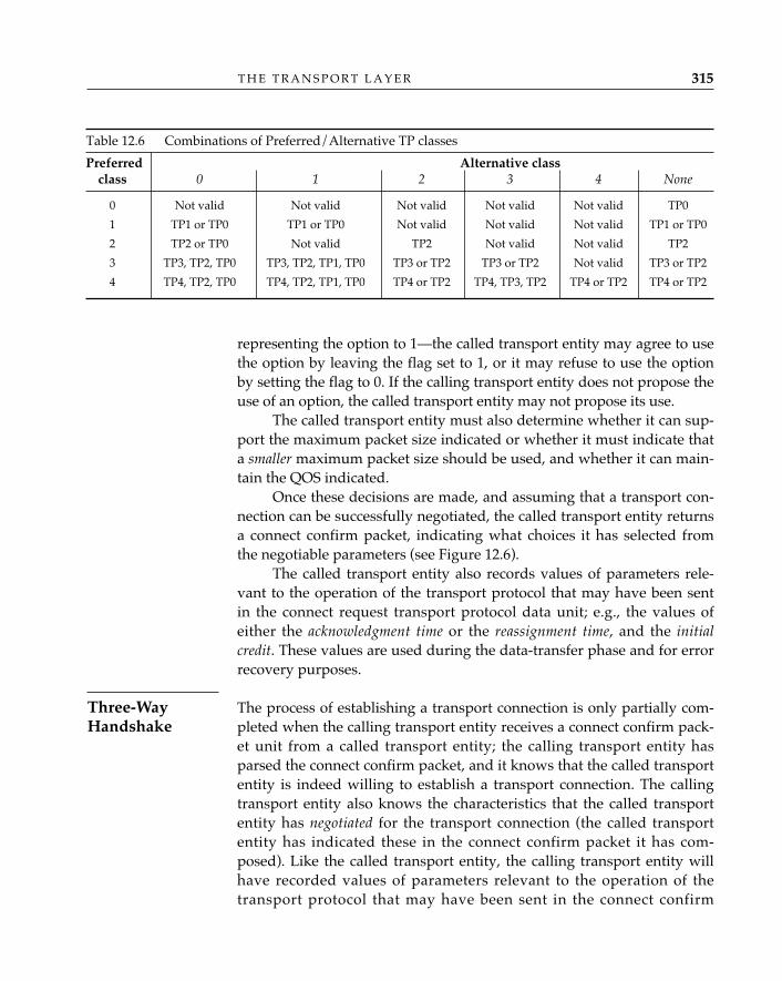
representing the option to 1—the called transport entity may agree to usethe option by leaving the flag set to 1, or it may refuse to use the optionby setting the flag to 0. If the calling transport entity does not propose theuse of an option, the called transport entity may not propose its use.
The called transport entity must also determine whether it can sup-port the maximum packet size indicated or whether it must indicate thata smaller maximum packet size should be used, and whether it can main-tain the QOS indicated.
Once these decisions are made, and assuming that a transport con-nection can be successfully negotiated, the called transport entity returnsa connect confirm packet, indicating what choices it has selected fromthe negotiable parameters (see Figure 12.6).
The called transport entity also records values of parameters rele-vant to the operation of the transport protocol that may have been sentin the connect request transport protocol data unit; e.g., the values ofeither the acknowledgment time or the reassignment time, and the initialcredit. These values are used during the data-transfer phase and for errorrecovery purposes.
The process of establishing a transport connection is only partially com-pleted when the calling transport entity receives a connect confirm pack-et unit from a called transport entity; the calling transport entity hasparsed the connect confirm packet, and it knows that the called transportentity is indeed willing to establish a transport connection. The callingtransport entity also knows the characteristics that the called transportentity has negotiated for the transport connection (the called transportentity has indicated these in the connect confirm packet it has com-posed). Like the called transport entity, the calling transport entity willhave recorded values of parameters relevant to the operation of thetransport protocol that may have been sent in the connect confirm
T H E T R A N S P O R T L A Y E R 315
Table 12.6 Combinations of Preferred/Alternative TP classes
Preferred Alternative classclass 0 1 2 3 4 None
0 Not valid Not valid Not valid Not valid Not valid TP0
1 TP1 or TP0 TP1 or TP0 Not valid Not valid Not valid TP1 or TP0
2 TP2 or TP0 Not valid TP2 Not valid Not valid TP2
3 TP3, TP2, TP0 TP3, TP2, TP1, TP0 TP3 or TP2 TP3 or TP2 Not valid TP3 or TP2
4 TP4, TP2, TP0 TP4, TP2, TP1, TP0 TP4 or TP2 TP4, TP3, TP2 TP4 or TP2 TP4 or TP2
Three-WayHandshake
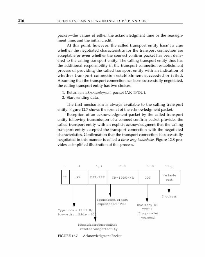
O P E N S Y S T E M S N E T W O R K I N G : T C P / I P A N D O S I316
packet—the values of either the acknowledgment time or the reassign-ment time, and the initial credit.
At this point, however, the called transport entity hasn’t a cluewhether the negotiated characteristics for the transport connection areacceptable or even whether the connect confirm packet has been deliv-ered to the calling transport entity. The calling transport entity thus hasthe additional responsibility in the transport connection-establishmentprocess of providing the called transport entity with an indication ofwhether transport connection establishment succeeded or failed.Assuming that the transport connection has been successfully negotiated,the calling transport entity has two choices:
1. Return an acknowledgment packet (AK TPDU).2. Start sending data.
The first mechanism is always available to the calling transportentity. Figure 12.7 shows the format of the acknowledgment packet.
Reception of an acknowledgment packet by the called transportentity following transmission of a connect confirm packet provides thecalled transport entity with an explicit acknowledgment that the callingtransport entity accepted the transport connection with the negotiatedcharacteristics. Confirmation that the transport connection is successfullynegotiated in this manner is called a three-way handshake. Figure 12.8 pro-vides a simplified illustration of this process.
FIGURE 12.7 Acknowledgment Packet
LI AK DST-REF
Type code = AK 0110,low-order nibble = 0000
1 2 3, 4 5–8 9–10
YR-TPDU-NR
Identifies requested TC atremote transport entity
Variablepart
11–p
CDT
Sequence no. of nextexpected DT TPDU How many DT
TPDUsI’m gonna letyou send
Checksum
T H E T R A N S P O R T L A Y E R 317
Relevant information encoded in the acknowledgment packet in-cludes:
• Destination reference, which contains the value of the calling trans-port entity’s reference number.
• Your transport protocol data unit number (YR-TPDU-NR), which con-tains the value of the next expected sequence number (n), implicitlyacknowledging the receipt of all transport protocol data packets upto and including sequence number n–1 (modulo 27 arithmetic ifnormal formats, modulo 231 if extended formats). Sequence num-bers are used in the data-transfer phase of a transport connection todistinguish packets containing normal data from one another andto assist in determining whether data packets have arrived in orderor have been lost or duplicated. The OSI transport protocol beginsevery transport connection with an initial sequence number of 0;since no data have yet been transferred, YR-TPDU-NR here con-tains a value of 1.
• CDT contains the initial credit allocated by the calling transport entityto the called transport entity (the number of transport protocol datapackets I’ll allow you to send before you must wait for me toacknowledge that I’ve received them).
• Other parameters, including a checksum computed on the acknow-ledgment packet and an acknowledgment sequence number (see“Normal Data Transfer in OSI transport protocols,” later in thischapter).
A second mechanism is available for situations in which the calledtransport entity has indicated a non-0 initial credit value in the connec-tion packet. The calling transport entity then has the option of immedi-ately sending any normal or expedited transport service user data wait-ing for transfer; the first data packet (DT TPDU) or expedited data packet(ED TPDU) received by the called transport entity in this case is inter-preted as a completion of the three-way handshake (again, refer toFigure 12.8).
Setting It All to UnixIf one were to trace the OSI transport connection-establishment processthrough the UNIX system calls described earlier in this chapter and theassociated transport protocol state machine, then trace the packets thattraversed the network while the process took place, and assuming that
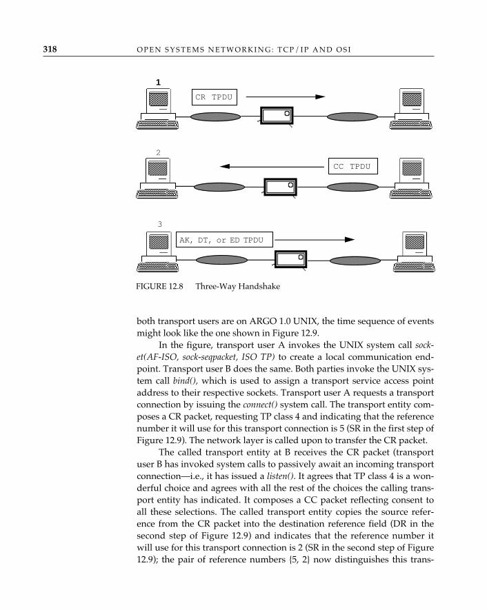
O P E N S Y S T E M S N E T W O R K I N G : T C P / I P A N D O S I318
both transport users are on ARGO 1.0 UNIX, the time sequence of eventsmight look like the one shown in Figure 12.9.
In the figure, transport user A invokes the UNIX system call sock-et(AF-ISO, sock-seqpacket, ISO TP) to create a local communication end-point. Transport user B does the same. Both parties invoke the UNIX sys-tem call bind(), which is used to assign a transport service access pointaddress to their respective sockets. Transport user A requests a transportconnection by issuing the connect() system call. The transport entity com-poses a CR packet, requesting TP class 4 and indicating that the referencenumber it will use for this transport connection is 5 (SR in the first step ofFigure 12.9). The network layer is called upon to transfer the CR packet.
The called transport entity at B receives the CR packet (transportuser B has invoked system calls to passively await an incoming transportconnection—i.e., it has issued a listen(). It agrees that TP class 4 is a won-derful choice and agrees with all the rest of the choices the calling trans-port entity has indicated. It composes a CC packet reflecting consent toall these selections. The called transport entity copies the source refer-ence from the CR packet into the destination reference field (DR in thesecond step of Figure 12.9) and indicates that the reference number itwill use for this transport connection is 2 (SR in the second step of Figure12.9); the pair of reference numbers {5, 2} now distinguishes this trans-
1
CR TPDU
CC TPDU
2
3
AK, DT, or ED TPDU
FIGURE 12.8 Three-Way Handshake
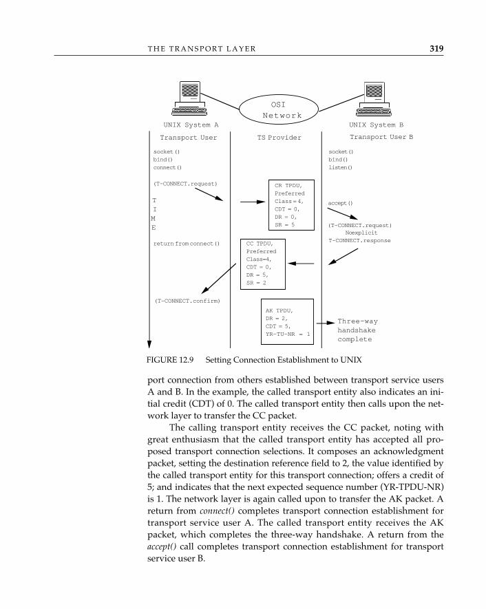
T H E T R A N S P O R T L A Y E R 319
port connection from others established between transport service usersA and B. In the example, the called transport entity also indicates an ini-tial credit (CDT) of 0. The called transport entity then calls upon the net-work layer to transfer the CC packet.
The calling transport entity receives the CC packet, noting withgreat enthusiasm that the called transport entity has accepted all pro-posed transport connection selections. It composes an acknowledgmentpacket, setting the destination reference field to 2, the value identified bythe called transport entity for this transport connection; offers a credit of5; and indicates that the next expected sequence number (YR-TPDU-NR)is 1. The network layer is again called upon to transfer the AK packet. Areturn from connect() completes transport connection establishment fortransport service user A. The called transport entity receives the AKpacket, which completes the three-way handshake. A return from theaccept() call completes transport connection establishment for transportservice user B.
FIGURE 12.9 Setting Connection Establishment to UNIX
Transport User B
socket ()bind()connect()
(T-CONNECT.request)
(T-CONNECT.request)No explicit
T-CONNECT.response
CR TPDU,PreferredClass = 4,CDT = 0,DR = 0,SR = 5
CC TPDU,PreferredClass=4,CDT = 0,DR = 5,SR = 2
return from connect()
(T-CONNECT.confirm)
AK TPDU,DR = 2,CDT = 5,YR-TU-NR = 1
Transport User TS Provider
socket()bind()listen()
accept()
Three-wayhandshakecomplete
TIME
OSINetwork
UNIX System BUNIX System A
O P E N S Y S T E M S N E T W O R K I N G : T C P / I P A N D O S I320
Frozen ReferencesAn important consideration when using references is providing a mecha-nism to avoid reuse of a reference to identify a new transport connectionwhile a packet associated with a previous use of the same reference maystill be “trollicking”10 along a network connection or bounding its wayalong as a connectionless NPDU. A reference would be reused when thevalue of the 16-bit reference counter “wraps” in modulo 2 arithmetic;although the circumstances under which this might occur seem extraor-dinary, betting the ranch that it won’t isn’t a very good idea. A procedurecalled frozen references offers some guidance to the implementer on howto deal with this phenomenon. In TP4, one way to bound the time (L) tofreeze a reference is to wait a minimum of the computed or estimatedround-trip time—the sum of the time required to transfer an NSDU fromthe local transport entity to the remote transport entity (MLR) and backagain (MRL)—plus the value of acknowledgment time the remote transportentity indicated in the CR transport protocol data unit (AR), plus thevalue of what is known as the persistence time (R), which is how long thelocal transport entity will try to resend an unacknowledged transportprotocol data unit before “giving up.” The formula is:
L = MLR + MRL + R + AR
Like all simple things, however, this formula has its weaknesses(see “Timers and Open Transport Protocols,” later in this chapter). Inpractice, this value of L may be too large; better too large, however, thantoo small! One must remember the purpose of the timer and choose avalue that can be lived with.
TCP Connection EstablishmentThe synchronize stream (SYN) process of TCP is functionally equivalent toconnection establishment in the OSI transport protocol. TCP operates asa pair of independent streams of (octets of) data between upper-layerprotocols. The synchronization process establishes the beginning of thebyte stream in both directions of information flow. During SYN process-
10. “Trollicking” is derived from the word trundle, meaning “to roll on little wheels; tobowl along,” and frollicking, meaning “dancing, playing tricks, or frisking about.” Anytransport packets remaining in a network connection during a “frozen references” timeperiod clearly could only be there to cause mischief . . .
T H E T R A N S P O R T L A Y E R 321
ing, information is exchanged between TCP processes that is similar tothe information negotiated (or implied) during OSI transport connectionestablishment:
• Addressing: The named sockets (source and destination port addresses)for the upper-layer protocol pairs that will use the TCP connectionare exchanged during the SYN phase.
• Initial sequence number (ISN): All OSI transport protocol classesbegin a transport connection using an initial sequence number of 0.TCP offers greater latitude, allowing TCP entities to identify theinitial octet sequence number in the SYN segment.
• Data offset: contains the number of 32-bit words in the TCP segmentheader; and therefore points to the first octet of user data.
• Window: Similar to OSI TP’s credit, the value in the window fieldindicates the number of bytes of information the originator of theSYN is willing to accept.
• Checksum: A 16-bit arithmetic checksum is computed on the headerand data of all TCP segments.
• Maximum segment size (MSS): Upper-layer protocols negotiate themaximum transport segment size (in octets). The default value onthe Internet for TCP maximum segment size is 536 bytes (RFC879).11
Unlike OSI’s transport protocol, all TCP segments have the sameformat.12 Figure 12.10 illustrates the encodings of fields significant for theSYN segment.
Many of the option facilities negotiated in OSI TP connection estab-lishment are nonoptions in TCP. For example, urgent data—the closestthing to OSI’s expedited data transfer—is a service that is always avail-able in TCP connections. TCP always uses explicit flow control. TCP isonly operated over a datagram service. And TCP wouldn’t know receiptconfirmation if it were bitten by the warty little beast.
To confirm the establishment of a TCP segment, the responding
11. Extensions to TCP by Van Jacobson, R. Braden, and D. Borman (RFC 1323) describehow large segment sizes and windows are negotiated by TCPs; like the amendment to theOSI transport protocol, this mechanism allows TCP entities to negotiate and use very largeTCP packets, necessary for networks that exhibit high bandwidth but have long round-tripdelays. Van Jacobson and company have colloquially termed such transmission facilities“long fat networks (LFNs),” pronounced “elephan(t)s.” 12. The Internet convention for illustrating protocol headers in its standards is to depictthe fields in 32-bit sequences. In this chapter, the authors have elected to draw both OSItransport protocol and TCP headers according to ISO conventions (with apologies to theInternet community).
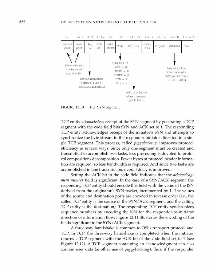
O P E N S Y S T E M S N E T W O R K I N G : T C P / I P A N D O S I322
TCP entity acknowledges receipt of the SYN segment by generating a TCPsegment with the code field bits SYN and ACK set to 1. The respondingTCP entity acknowledges receipt of the initiator’s SYN and attempts tosynchronize the byte stream in the responder-initiator direction in a sin-gle TCP segment. This process, called piggybacking, improves protocolefficiency in several ways. Since only one segment must be created andtransmitted to accomplish two tasks, less processing is devoted to proto-col composition/decomposition. Fewer bytes of protocol header informa-tion are required, so less bandwidth is required. And since two tasks areaccomplished in one transmission, overall delay is improved.
Setting the ACK bit in the code field indicates that the acknowledg-ment number field is significant. In the case of a SYN/ACK segment, theresponding TCP entity should encode this field with the value of the ISNderived from the originator’s SYN packet, incremented by 1. The valuesof the source and destination ports are encoded in reverse order (i.e., thecalled TCP entity is the source of the SYN/ACK segment, and the callingTCP entity is the destination). The responding TCP entity synchronizessequence numbers by encoding the ISN for the responder-to-initiatordirection of information flow. Figure 12.11 illustrates the encoding of thefields significant to the SYN/ACK segment.
A three-way handshake is common to OSI’s transport protocol andTCP. In TCP, the three-way handshake is completed when the initiatorreturns a TCP segment with the ACK bit of the code field set to 1 (seeFigure 12.12). A TCP segment containing an acknowledgment can alsocontain user data (another use of piggybacking); thus, if the responder
FIGURE 12.10 TCP SYN Segment
Internet portnumbers ofapplication
Initial sequencenumber (ISN),
initiator direction
URGENT=0ACK = 0PUSH = 0RESET = 0SYN = 1FIN = 0
Initial windowadvertisementby initiator
Sourceport
Destport
Seqno.
Ackno.
Dataoffset
Code WindowCheck-sum
Urgent Options Pad
1, 3, 4 5–8 9–12 13 14 15, 16 17, 18 19, 20 21–p p + 1, q
Max seg sizeWindow scale
SACK permitted(RFC 1323)
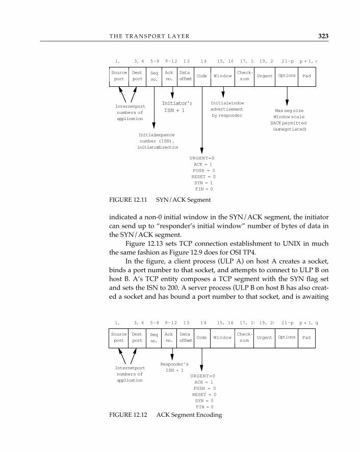
T H E T R A N S P O R T L A Y E R 323
indicated a non-0 initial window in the SYN/ACK segment, the initiatorcan send up to “responder’s initial window” number of bytes of data inthe SYN/ACK segment.
Figure 12.13 sets TCP connection establishment to UNIX in muchthe same fashion as Figure 12.9 does for OSI TP4.
In the figure, a client process (ULP A) on host A creates a socket,binds a port number to that socket, and attempts to connect to ULP B onhost B. A’s TCP entity composes a TCP segment with the SYN flag setand sets the ISN to 200. A server process (ULP B on host B has also creat-ed a socket and has bound a port number to that socket, and is awaiting
FIGURE 12.11 SYN/ACK Segment
Internet portnumbers ofapplication
Initial sequencenumber (ISN),initiator direction
URGENT=0ACK = 1PUSH = 0RESET = 0SYN = 1FIN = 0
Initial windowadvertisementby responder
Sourceport
Destport
Seqno.
Ackno.
Dataoffset
Code WindowCheck-sum
Urgent Options Pad
1, 3, 4 5–8 9–12 13 14 15, 16 17, 18 19, 20 21–p p + 1, q
Max seg sizeWindow scale
SACK permitted(as negotiated)
Initiator’sISN + 1
FIGURE 12.12 ACK Segment Encoding
Internet portnumbers ofapplication
URGENT=0ACK = 1PUSH = 0RESET = 0SYN = 0FIN = 0
Sourceport
Destport
Seqno.
Ackno.
Dataoffset
Code WindowCheck-sum
Urgent Options Pad
1, 3, 4 5–8 9–12 13 14 15, 16 17, 18 19, 20 21–p p + 1, q
Responder’sISN + 1
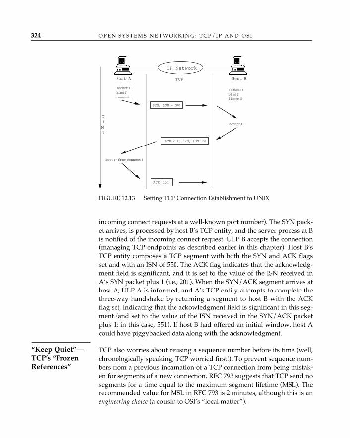
incoming connect requests at a well-known port number). The SYN pack-et arrives, is processed by host B’s TCP entity, and the server process at Bis notified of the incoming connect request. ULP B accepts the connection(managing TCP endpoints as described earlier in this chapter). Host B’sTCP entity composes a TCP segment with both the SYN and ACK flagsset and with an ISN of 550. The ACK flag indicates that the acknowledg-ment field is significant, and it is set to the value of the ISN received inA’s SYN packet plus 1 (i.e., 201). When the SYN/ACK segment arrives athost A, ULP A is informed, and A’s TCP entity attempts to complete thethree-way handshake by returning a segment to host B with the ACKflag set, indicating that the ackowledgment field is significant in this seg-ment (and set to the value of the ISN received in the SYN/ACK packetplus 1; in this case, 551). If host B had offered an initial window, host Acould have piggybacked data along with the acknowledgment.
TCP also worries about reusing a sequence number before its time (well,chronologically speaking, TCP worried first!). To prevent sequence num-bers from a previous incarnation of a TCP connection from being mistak-en for segments of a new connection, RFC 793 suggests that TCP send nosegments for a time equal to the maximum segment lifetime (MSL). Therecommended value for MSL in RFC 793 is 2 minutes, although this is anengineering choice (a cousin to OSI’s “local matter”).
O P E N S Y S T E M S N E T W O R K I N G : T C P / I P A N D O S I324
FIGURE 12.13 Setting TCP Connection Establishment to UNIX
socket ()bind()connect(
socket()bind()listen()
accept()
SYN, ISN = 200
ACK 201, SYN, ISN 550
return from connect(
ACK 551
Host A Host BTCP
TIME
IP Network
“Keep Quiet”—TCP’s “FrozenReferences”
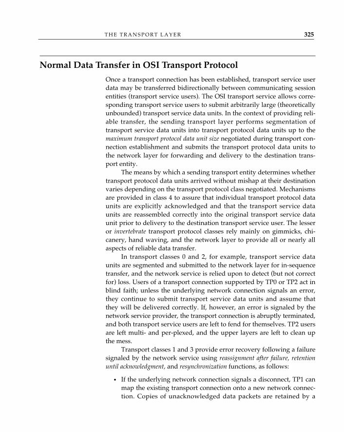
T H E T R A N S P O R T L A Y E R 325
Normal Data Transfer in OSI Transport Protocol
Once a transport connection has been established, transport service userdata may be transferred bidirectionally between communicating sessionentities (transport service users). The OSI transport service allows corre-sponding transport service users to submit arbitrarily large (theoreticallyunbounded) transport service data units. In the context of providing reli-able transfer, the sending transport layer performs segmentation oftransport service data units into transport protocol data units up to themaximum transport protocol data unit size negotiated during transport con-nection establishment and submits the transport protocol data units tothe network layer for forwarding and delivery to the destination trans-port entity.
The means by which a sending transport entity determines whethertransport protocol data units arrived without mishap at their destinationvaries depending on the transport protocol class negotiated. Mechanismsare provided in class 4 to assure that individual transport protocol dataunits are explicitly acknowledged and that the transport service dataunits are reassembled correctly into the original transport service dataunit prior to delivery to the destination transport service user. The lesseror invertebrate transport protocol classes rely mainly on gimmicks, chi-canery, hand waving, and the network layer to provide all or nearly allaspects of reliable data transfer.
In transport classes 0 and 2, for example, transport service dataunits are segmented and submitted to the network layer for in-sequencetransfer, and the network service is relied upon to detect (but not correctfor) loss. Users of a transport connection supported by TP0 or TP2 act inblind faith; unless the underlying network connection signals an error,they continue to submit transport service data units and assume thatthey will be delivered correctly. If, however, an error is signaled by thenetwork service provider, the transport connection is abruptly terminated,and both transport service users are left to fend for themselves. TP2 usersare left multi- and per-plexed, and the upper layers are left to clean upthe mess.
Transport classes 1 and 3 provide error recovery following a failuresignaled by the network service using reassignment after failure, retentionuntil acknowledgment, and resynchronization functions, as follows:
• If the underlying network connection signals a disconnect, TP1 canmap the existing transport connection onto a new network connec-tion. Copies of unacknowledged data packets are retained by a
sending transport entity until a new network connection is opened.The retained packets are then retransmitted by the sending transportentity (remember, information flow across a transport connection isbidirectional, so both parties may act as senders) and explicitlyacknowledged by the receiver, thus resynchronizing the informationflow of the transport connection.13
• If the underlying network connection signals an error (a reset),transport entities retransmit unacknowledged data packets to re-synchronize the data streams in both directions (over the same net-work connection).
Remember, these Mickey Mouse mechanisms are considered to besufficient because acceptable levels of service quality are purportedly pro-vided by the network service; in the real world, they are probably ade-quate when both transport service users subscribe to the same public net-work provider or are attached to the same physical subnetwork. Sinceyou can’t be too careful these days, it’s better to practice “safe network-ing” than to deny the possibility of network connection failures and say,“Well, it won’t happen to me.”
A major concern in maintaining service quality in a network is seeingthat information flows into the network at a manageable rate. Just as ahighway can handle only so many automobiles before traffic initiallyslows and then comes to a stop, networks can only switch a finite num-ber of packets before experiencing similar congestion. To prevent trafficjams on major California highways surrounding Los Angeles, for exam-ple, traffic signals are positioned on the entrance ramps. These allowautomobiles to enter the roadway at intervals that vary according to theamount of traffic already present on the roadway. By regulating the flowof automobiles onto the roadway, congestion is temporarily avoided.14
Of course, roads are rarely built to handle peak loads (rush hours), andunder these conditions, highway congestion inevitably occurs (some-times the traffic lights at entranceways are turned off, a visible sign ofsurrender or congestion collapse).
Similar techniques are used in networks to avoid congestion. The
O P E N S Y S T E M S N E T W O R K I N G : T C P / I P A N D O S I326
13. Copies of connect request and connect confirm TPDUs—and for reasons unknown,TPDUs used for connection release (DR and DC TPDUs)—are retained in the samefashionto permit completion of transport connection establishment or release if the net-work connection disconnects during that phase of operation. 14. Los Angelenos may deny that this works at all, but the fault lies in the fact that con-gestion-avoidance mechanisms have been applied to highways that have existed in a con-gested state for decades.
Flow Control
T H E T R A N S P O R T L A Y E R 327
rate of information flow into a network (incoming packets) is regulatedaccording to the network’s ability to switch packets. Flow control is aclassic networking problem, and a variety of flow-control techniques havebeen employed to avoid congestion. Of these, OSI employs both implicitand explicit flow-control techniques in its transport protocol classes.
In a public network service, users subscribe to and expect a certainrate of throughput (often, a negotiated quality of service characteristic);thus, it is no surprise to find that transport classes 0 and 1 are designedto rely entirely on the network service provider to regulate the flow oftransport protocol data units. This implicit flow control15 is straightfor-ward (and autocratic): the sending transport entity submits transportprotocol data units to the network service (in the form of NSDUs); thenetwork layer accepts the NSDUs and forwards them at a rate it chooses,typically one consistent with maintaining some degree of uniform ser-vice quality for all subscribers. Transport service users continue to sub-mit transport service data units, and TP0 and TP1 faithfully continue tocreate transport protocol data units and submit them to the networklayer until the local buffer pool allocated to the transport layer isexhausted. TP0 and TP1 then halt and accept no transport service dataunits from the session layer; the effect of halting percolates through theupper layers and has the same back-pressure effect on information flowthat (gradually) closing a faucet has on the flow of water. Normal userdata cease to flow out of the end system until the back-pressure condi-tion is eased; i.e., until the network layer accepts a sufficient numberfrom the queue of previously submitted NSDUs to allow the flow ofinformation to continue.
A shortcoming of this form of flow control is that although the net-work layer is somewhat insulated from congestion, an end systemreceiving packets has no explicit means of indicating that it cannot acceptpackets at the incoming rate. TP0 and TP1 again rely upon the networkservice to deal with this situation; protocols used to provide the OSI con-nection-oriented network service (e.g., X.25) have facilities that enable anend system to signal that it is temporarily unable to receive incomingpackets (there are no explicit network service primitives to signal “con-gestion”; how the transport layer indicates an “unable to receive” state isa local matter).
Flow control is no less important in private internets; the mecha-nisms, however, are more democratic. All transport entities are expected
15. Implicit flow control is optionally available in TP2 and must be negotiated duringconnection establishment.
O P E N S Y S T E M S N E T W O R K I N G : T C P / I P A N D O S I328
to participate in an explicit flow-control process. TP4, for example, uses asliding window mechanism; very simply stated, this form of flow controlproceeds as follows:
1. Each transport entity indicates a number of data packets that it isable to receive; this is called the credit (CDT). The initial credit valueis exchanged during connection establishment. During data trans-fer, CDT is added to the value of the highest sequence numberacknowledged (called the lower window edge [LWE], initially 0) tocreate the send window. This sum is called the upper window edge(UWE).
2. A sending transport entity sends a number of transport protocoldata units equal to the credit, then waits for an explicit acknowledg-ment packet before continuing to send.
3. Upon reception of an acknowledgment packet, a sending transportentity extracts the value of the sequence number (YR-TPDU-NR)from the AK packet and uses this value as the new LWE; it alsoextracts the value of CDT from the AK packet and adds this to thenew LWE to determine the new UWE.
As steps 2 and 3 are repeated, the sequence numbers are incrementedusing modulo 2 arithmetic, and the send window “slides.” By increasingor decreasing the value of CDT, the size of the send window increases ordecreases. This is also called opening or closing the send window.
Different policies are applied to determine the appropriate value ofCDT. One simple policy for determining the initial value of CDT is todivide the number of bytes of buffer space available for the receiver sideof the transport protocol by the maximum transport protocol data unitsize to yield an integer value for CDT; for example, if there are 4,096octets of receive buffer available, and the maximum transport protocoldata unit size negotiated for this transport connection is 1,024, then CDTcould be set initially to 4.
Reliability Mechanisms to Deal with the Real WorldOf the OSI transport protocol classes, only TP4 was developed to dealwith real-world situations in which, despite the best efforts exerted bythe network layer, bad things happen to transport protocol data units ontheir way from source to destination: specifically, transport protocol dataunits may get lost, multiple copies of the same transport protocol dataunit may be delivered, transport protocol data units may be delivered to
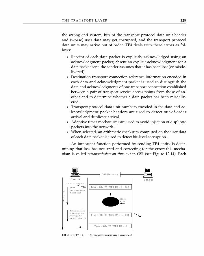
T H E T R A N S P O R T L A Y E R 329
the wrong end system, bits of the transport protocol data unit headerand (worse) user data may get corrupted, and the transport protocoldata units may arrive out of order. TP4 deals with these errors as fol-lows:
• Receipt of each data packet is explicitly acknowledged using anacknowledgment packet; absent an explicit acknowledgment for adata packet sent, the sender assumes that it has been lost (or misde-livered).
• Destination transport connection reference information encoded ineach data and acknowledgment packet is used to distinguish thedata and acknowledgments of one transport connection establishedbetween a pair of transport service access points from those of an-other and to determine whether a data packet has been misdeliv-ered.
• Transport protocol data unit numbers encoded in the data and ac-knowledgment packet headers are used to detect out-of-orderarrival and duplicate arrival.
• Adaptive timer mechanisms are used to avoid injection of duplicatepackets into the network.
• When selected, an arithmetic checksum computed on the user dataof each data packet is used to detect bit-level corruption.
An important function performed by sending TP4 entity is deter-mining that loss has occurred and correcting for the error; this mecha-nism is called retransmission on time-out in OSI (see Figure 12.14). Each
T-DATA.reques
Type = DT, YR-TPDU-NR = 1, EOT
Retransmissiontimer expires;resend packet;restart timer T1
Type = DT, YR-TPDU-NR = 1, EOTStartretransmissiontimer (T1)
Type = AK, YR-TPDU-NR = 2
User A User B
TIME
BlackHole
OSI Network
FIGURE 12.14 Retransmission on Time-out
O P E N S Y S T E M S N E T W O R K I N G : T C P / I P A N D O S I330
time a TP4 entity sends a DT transport protocol data unit, it runs aretransmission timer (T1); if the explicit acknowledgment of receipt of thedata packet is not received by the sender prior to the expiration of the T1timer, the sender assumes that the data packet is lost and retransmits it.
The detailed manner in which the sender and receiver cooperate toachieve reliability through retransmission is best understood by examin-ing each separately.
Like the lesser transport protocol classes, the sending TP4 transport enti-ty segments transport service data units into data packets (if necessary);the data packets are often a fixed size (except the last segment of a pack-et), up to the maximum packet size negotiated during connection estab-lishment.16 A sequence number is assigned to each data packet (YR-TPDU-NR in Figure 12.14); the initial value of the YR-TPDU-NR field isalways 0, and YR-TPDU-NR is incremented by 1 for all subsequent datapackets transferred in the transport connection. The combination of DST-REF and YR-TPDU-NR is used to differentiate transport protocol dataunits of different transport connections multiplexed between the samepair of transport entities. If multiple transport protocol data units arerequired to transfer a single transport service data unit, the end of trans-port service data unit (EOT) bit in the data packet header is set to 0 in allbut the packet containing the final segment of the transport service dataunit (indicating that there are more user data to come); the EOT bit is setto 1 in the data packet containing the final segment of the transport ser-vice data unit (see Figure 12.15).
Initially, the sending TP4 entity may send one or more data packets,up to the value indicated in the CDT field of
• The connect request packet if the sender was the responder duringconnection establishment.
• The connect confirm packet if the sender was the initiator duringconnection establishment.
The sender retains a copy of each data packet sent. It also maintainsinformation about the number of transport protocol data units it has sent,as well as the sequence numbers of those packets, and the sequence numberof the next data packet the receiver expects17 (the lower window edge).
Sender TP4Responsibilities
16. In practice, the maximum packet size should be less than or equal to the maximumNSDU size offered by the network layer between the source and destination end systems.17. Sequence numbers in acknowledgment packets are interpreted as meaning “Iacknowledge receipt of all data packets, in sequence, up to but not including the sequencenumber indicated in the YR-TPDU-NR field.”
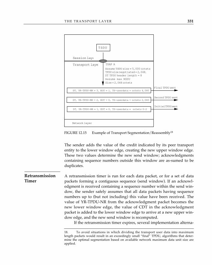
The sender adds the value of the credit indicated by its peer transportentity to the lower window edge, creating the new upper window edge.These two values determine the new send window; acknowledgmentscontaining sequence numbers outside this window are as-sumed to beduplicates.
A retransmission timer is run for each data packet, or for a set of datapackets forming a contiguous sequence (send window). If an acknowl-edgment is received containing a sequence number within the send win-dow, the sender safely assumes that all data packets having sequencenumbers up to (but not including) this value have been received. Thevalue of YR-TPDU-NR from the acknowledgment packet becomes thenew lower window edge, the value of CDT in the acknowledgmentpacket is added to the lower window edge to arrive at a new upper win-dow edge, and the new send window is recomputed.
If the retransmission timer expires, several implementation alterna-
T H E T R A N S P O R T L A Y E R 331
FIGURE 12.15 Example of Transport Segmentation/Reassembly18
TSDU
Assume TSDU size = 5,000 octetsTPDU size negotiated = 2,048,DT TPDU header length = 8
DT, YR-TPDU-NR = 1, EOT = 0, TS-userdata = octets 0–2
DT, YR-TPDU-NR = 2, EOT = 0, TS-userdata = octets 2,040–
DT, YR-TPDU-NR = 3, EOT = 1, TS-userdata = octets 4,080–
Session laye
Transport layer
Final TPDU sent
Second TPDU sent
Initial TPDU sent
TSAP A
Network layer
Assume max NSDUSize = 2,048 octets
18. To avoid situations in which dividing the transport user data into maximumlength packets would result in an exceedingly small “final” TPDU, algorithms that deter-mine the optimal segmentation based on available network maximum data unit size areapplied.
RetransmissionTimer
O P E N S Y S T E M S N E T W O R K I N G : T C P / I P A N D O S I332
tives are available to the sender; for example, it can update the lowerwindow edge and retransmit only the data packet whose YR-TPDU-NRis equal to the value of the lower window edge, or it can retransmit all ora part of the reevaluated send window (from new lower window edge toold upper window edge). (The value of the retransmission timer is dis-cussed separately; see “Timers and Open Transport Protocols,” later inthis chapter.)
The primary responsibilities of the receiver are to explicitly acknowledgecorrect receipt of individual data packets using an acknowledgmentpacket, correctly reassemble data packets into transport service dataunits (when necessary), and deliver transport service data units to thecalled transport service user. Acknowledgment packets are generated
• Upon successful receipt and processing of a data packet. • When advertised credit is reached (the window is full).• To allocate credit; i.e., to increase or reduce the upper window edge
(to open or close the window) and thus identify the number of datapackets the receiver is willing to handle. (Often, the initial value is asimple calculation of available receive buffer size divided by thenegotiated maximum packet size.)
A receiver TP4 entity also returns an acknowledgment packet upon
• Receipt of a duplicate data packet. • Expiration of the window timer (see “Timers and Open Transport
Protocols”).
When the receiver determines that a transport service data unit isarriving in segments (multiple data packets), it must also worry aboutcorrect reassembly of the transport service data unit. The retransmissionprocedures assure that the sender will resend data packets the receiverdoes not acknowledge (they were not received or were received andfailed the checksum computation), and the receiver weeds out duplicatedata packets using the TPDU numbering and reference fields of the datapacket, but transport protocol data packets may still arrive out of order.One possible strategy that a receiver may use to correctly order datapackets that have arrived out of order is to maintain
• An in-order list, containing data packets units of a partially reas-sembled transport service data unit that arrive in sequence.
• An out-of-order list, containing data packets of a partially reassem-bled transport service data unit that arrive out of sequence.
• A next expected transport protocol data unit number (NEXT-EX-
Receiver TP4Responsibilities
T H E T R A N S P O R T L A Y E R 333
PECTED-TPDU-NR) variable, containing the value of the nextexpected TPDU sequence number (i.e., the sequence number of thedata packet that would sequentially follow the last data packet inthe in-order list).
When a data packet arrives, if the value of YR-TPDU-NR transportprotocol data unit NR is not the same as the value of next expected trans-port protocol data unit number, the receiver adds this data packet to theout-of-order list, in order with respect to the rest of that list. If a datapacket arrives and the value of YR-TPDU-NR is the same as the value ofnext expected transport protocol data unit number, the receiver adds the datapacket to the tail of the in-order list, checks the out-of-order list for oneor more data packets that follow the newly arrived data packet insequence, and moves these to the in-order list. If at any time in this pro-cess a data packet is encountered containing the final segment of thetransport service data unit (EOT = 1), the process is stopped; otherwise,the receiver adjusts next expected transport protocol data unit number to con-tain the value of the sequence transport protocol data unit number of thenext expected data packet. Alternatively, the receiver can maintain onlyan in-order list and discard without explicitly acknowledging any datapackets received out of order; the sender will dutifully retransmit thesedata packets according to the retransmission on time-out procedures.
The receiver has an explicit mechanism—setting the value ofCDT—for controlling the number of transport protocol data units it isexpected to be able to receive at a given time. The receiver can increaseor decrease credit (open or close the send window) as necessary to exer-cise some control over the way its local resources are used. Suppose, forexample, that a transport implementation has 64K of buffer space. If amaximum packet size of 1K is negotiated for a transport connection, atheoretical credit of 64 is available; anticipating that multiple transportconnections to multiple destinations may be established, an implementa-tion may allocate an initial credit of 8 for up to eight transport connec-tions, then reduce the credit for all transport connections as additionaltransport connections share the buffer space. (It is expected that somerational value for the maximum number of concurrent transport connec-tions is applied in all implementations; certainly, here, the value must beless than 65!)
Like data packets, acknowledgment packets can also be lost, duplicated,corrupted, or delivered out of order. Failing to correct these errors fordata packets will corrupt user data; failing to correct these errors for
SequencingAcknowledgmentPackets in OSITP4
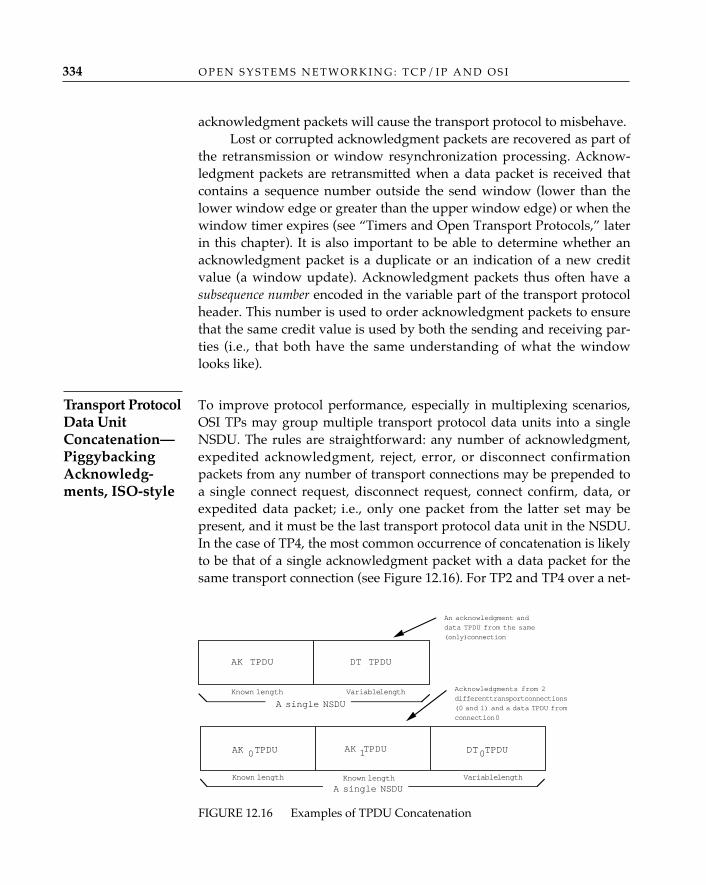
acknowledgment packets will cause the transport protocol to misbehave. Lost or corrupted acknowledgment packets are recovered as part of
the retransmission or window resynchronization processing. Acknow-ledgment packets are retransmitted when a data packet is received thatcontains a sequence number outside the send window (lower than thelower window edge or greater than the upper window edge) or when thewindow timer expires (see “Timers and Open Transport Protocols,” laterin this chapter). It is also important to be able to determine whether anacknowledgment packet is a duplicate or an indication of a new creditvalue (a window update). Acknowledgment packets thus often have asubsequence number encoded in the variable part of the transport protocolheader. This number is used to order acknowledgment packets to ensurethat the same credit value is used by both the sending and receiving par-ties (i.e., that both have the same understanding of what the windowlooks like).
To improve protocol performance, especially in multiplexing scenarios,OSI TPs may group multiple transport protocol data units into a singleNSDU. The rules are straightforward: any number of acknowledgment,expedited acknowledgment, reject, error, or disconnect confirmationpackets from any number of transport connections may be prepended toa single connect request, disconnect request, connect confirm, data, orexpedited data packet; i.e., only one packet from the latter set may bepresent, and it must be the last transport protocol data unit in the NSDU.In the case of TP4, the most common occurrence of concatenation is likelyto be that of a single acknowledgment packet with a data packet for thesame transport connection (see Figure 12.16). For TP2 and TP4 over a net-
O P E N S Y S T E M S N E T W O R K I N G : T C P / I P A N D O S I334
Transport ProtocolData UnitConcatenation—PiggybackingAcknowledg-ments, ISO-style
Variable length
An acknowledgment and
data TPDU from the same
(only) connection
0AK TPDU AK TPDU1 0DT TPDU
Known lengthKnown length
Acknowledgments from 2
different transport connections
(0 and 1) and a data TPDU from
connection 0
A single NSDU
DT TPDUAK TPDU
Known length Variable length
A single NSDU
FIGURE 12.16 Examples of TPDU Concatenation
T H E T R A N S P O R T L A Y E R 335
work connection, concatenation has additional benefits: one can, forexample, concatenate acknowledgments from different transport connec-tions with a single data packet, send a single large NSDU, and save“turnaround time.” Compared to the TCP piggyback mechanisms, inwhich one need only set the TCP acknowledgment AK flag to true andpopulate the TCP acknowledgment sequence number, this admittedly isoverhead and overkill—another demonstration that flexibility costs.
Data Transfer in TCP—More of the SameTCP’s name for retransmission on time-out is positive acknowledgment andretransmission. Mechanisms exist in TCP for detecting and correcting thesame set of errors as in TP4. What distinguishes TCP from TP4 in datatransfer is encoding rather than functionality; for example:
• TCP transfers octet streams, not fixed blocks of user data. The 32-bit sequence number in a TCP segment represents the number ofthe octet in the stream, not the number of the TCP packet.
• The TCP acknowledgment number indicates the next expectedoctet, as opposed to the next expected TCP segment.
• The acknowledgment flag may be set to true to indicate that theacknowledgment sequence number (and window) is significant indata segments in the return stream (piggybacking).
• The 16-bit TCP window indicates in octets the amount of data thereceiver is willing to accept in the next TCP segment(s); this valueis added to the acknowledgment sequence number to determinethe send window. Thus, window is TCP’s octet equivalent of TP4’scredit.
• A push bit in the code field of the TCP segment may be used todecrease delay; i.e., its use overrides TCP’s attempt to fill a maxi-mum segment sized packet before sending. (Although it can bemisused, push is not intended to be a delimiter of segments as isOSI’s EOT bit.)
Figure 12.17 depicts two TCP scenarios—successful transfer with pos-itive acknowledgment and loss followed by retransmission. Many of thesender and receiver responsibilities and strategies described for TP4 were
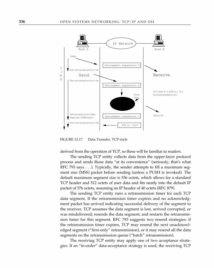
O P E N S Y S T E M S N E T W O R K I N G : T C P / I P A N D O S I336
derived from the operation of TCP, so these will be familiar to readers.The sending TCP entity collects data from the upper-layer protocol
process and sends those data “at its convenience” (seriously, that’s whatRFC 793 says . . .). Typically, the sender attempts to fill a maximum seg-ment size (MSS) packet before sending (unless a PUSH is invoked). Thedefault maximum segment size is 536 octets, which allows for a standardTCP header and 512 octets of user data and fits neatly into the default IPpacket of 576 octets, assuming an IP header of 40 octets (RFC 879).
The sending TCP entity runs a retransmission timer for each TCPdata segment. If the retransmission timer expires and no acknowledg-ment packet has arrived indicating successful delivery of the segment tothe receiver, TCP assumes the data segment is lost, arrived corrupted, orwas misdelivered; resends the data segment; and restarts the retransmis-sion timer for this segment. RFC 793 suggests two resend strategies: ifthe retransmission timer expires, TCP may resend the next unacknowl-edged segment (“first-only” retransmission), or it may resend all the datasegments on the retransmission queue (“batch” retransmission).
The receiving TCP entity may apply one of two acceptance strate-gies. If an “in-order” data-acceptance strategy is used, the receiving TCP
FIGURE 12.17 Data Transfer, TCP-style
SEND
Data segment, sequence no. 71
Data segment, sequence no. 71
Run retransmission time
Receive
ACK no. 1225
(Or user B's ACK no. 713could have been lost)
Host A Host B
Run retransmission time
Data segment, sequence no. 22
RECEIVERetransmission timerexpires; SEND again
TIME
Black
Hole
Run retransmission time
IP Network
Send
T H E T R A N S P O R T L A Y E R 337
entity accepts only data that arrive in octet-sequence order and discardsall other data. The receiving TCP entity returns an acknowledgment tothe sender and makes the octet stream available to the upper-layer proto-col process as it arrives. If an “in-window” data-acceptance strategy isemployed, the receiving TCP entity maintains segments containingoctets that arrive out of order separately from those that have arrived inorder and examines newly arrived data segments to determine whetherthe next expected octet in the ordered stream of octets has arrived. If so,the receiving TCP entity adds this segment’s worth of octets to the end ofthe octet stream that had previously arrived in order and looks at theout-of-order stream to see whether additional octets may now be ap-pended to the end of the in-order stream. The TCP entity returns anacknowledgment and makes the accumulated stream of in-order octetsavailable to the upper-layer protocol process.
An explicit acknowledgment is returned in a TCP segment (poten-tially “piggybacked” with data flowing in the opposite direction). Theacknowledgment sequence number X indicates that all octets up to but notincluding X have been received, and the next octet expected is atsequence number X. The segment window indicates the number of octetsthe receiver is willing to accept (beginning with sequence number X).Acknowledgment packets reflect only what has been received in se-quence; they do not acknowledge data packets that arrived successfullybut out of sequence.
When an acknowledgment packet arrives, the sending TCP entitymay choose to resend all unacknowledged data from sequence number Xup to the maximum permitted by the segment window. In theory, apply-ing the “batch” retransmission strategy results in more traffic but possiblyless delay. The sending TCP entity may resend only the data segmentcontaining the first unacknowledged octet. This negates a large windowand may increase delay, but it is preferred because it introduces less traf-fic into the network. Batch retransimssion strategies are generally regard-ed as bad ideas, since their excessive retransmission of segments is likelyto contribute to network congestion.
Window Considerations for TP4 and TCPManaging the send and receive windows is critical to the performance ofOSI and TCP networks. Every network has a finite forwarding capacity,and absent constant monitoring of network “busy-ness,” transport enti-ties can easily submit packets faster than the network can forward and
O P E N S Y S T E M S N E T W O R K I N G : T C P / I P A N D O S I338
deliver them, even if they are all dutifully abiding by the windows adver-tised for their respective transport connections (this is simply a case inwhich the sum of the advertised windows exceeds the capacity of the net-work). Networks that become too busy or congested do unkind thingssuch as discard packets. Since congestion has the undesirable effect ofcausing retransmission (either because delays increase and transport enti-ties presume loss and retransmit or because the network is in fact discard-ing packets due to congestion) and retransmission results in delay, it isimportant that transport implementations try their best not to retransmitunless they are very sure they must. On the other hand, too much cautionwill also cause delay; an overly conservative retransmission timer willwait too long before causing genuinely lost packets to be retransmitted.The trick, evidently, is to wait long enough, but not too long.
A number of different mechanisms are available to deal with thisconundrum, most of them applicable to both TCP and TP4. One of themost successful is called “slow-start” (Jacobson 1988). Slow-start is a sim-ple mechanism and follows a simple philosophy: as new transport con-nections are established, they shouldn’t upset the equilibrium that mayexist in a network by transmitting large amounts of data right away. Inother words, transport connections should not be opened with large win-dows (or credits); rather, the window (or credit) should initially be smalland should grow as evidence of the network’s ability to handle morepackets is returned in the form of acknowledgments for each packet sent.Slow-start recognizes that a receiver advertises a window or credit of acertain size based on the receiver’s ability to handle incoming packets,which is closely related to the availability of buffers and processingcycles at the receiver but has nothing whatsoever to do with congestionin the network. It does not follow, therefore, that the most appropriatestrategy for the sender is to immediately fill the window offered by thereceiver; the sender must also take into account the effect of its behavioron the network.19 Slow-start couples flow control (ensuring that a sender
19. A variation of the familiar “tragedy of the commons” applies to the behavior ofhosts sending traffic into an internetwork, since most of the algorithms that have beendevised for congestion avoidance and control in internetworks depend on a “good networkcitizen” collaboration among host transport protocol implementations to globally maxi-mize the traffic that can be handled by the network without congestion collapse. Anunscrupulous host can attempt to take advantage of its well-behaved neighbors by deliber-ately sending traffic into the network at a rate that would produce serious congestion butfor the willingness of other hosts to “back off” as the overall network load rises. This prob-lem has been addressed by a combination of legislation (the Internet standards require, forexample, that all Internet TCP implementations use Jacobson’s slow-start algorithm) andnegative reinforcement (operating the internetwork in such a way that “selfish host
T H E T R A N S P O R T L A Y E R 339
does not send faster than its receiver can receive) with congestion control(ensuring that the traffic generated by all senders does not overwhelmthe capacity of the network).20
A transport implementation using slow-start maintains two win-dows that govern the rate at which it sends packets: the normal “usable”window (the difference between the window or credit offered by thereceiver and the amount of outstanding [unacknowledged] data that arealready in the window) and a separate “congestion” window, which is arunning estimate of how much data can be sent without congesting thenetwork. The transport protocol then uses the congestion window, ratherthan the usable window, to control the rate at which it sends new data.(Correct operation of the transport protocol requires, of course, that thesize of the congestion window never exceed the size of the usable win-dow.)
Slow-start divides the lifetime of a transport connection into “phases.”The first phase begins when the connection is established. The conges-tion window at the beginning of a phase is always set to 1 packet (forTCP, this is the maximum segment size; for OSI transport, 1 transportprotocol data unit); thereafter, as long as no packets are lost, the conges-tion window is increased by 1 packet every time an acknowledgmentpacket is received, subject to an upper bound of either the current usablewindow (which the congestion window must never exceed) or the cur-rent “slow-start threshold” (which is half the value of the congestionwindow at the end of the previous phase). This has the effect of openingthe congestion window rapidly21 until a threshold (or absolute upperbound) is reached or a packet loss occurs (which suggests that the win-dow may have been opened too far).
The detection of a packet loss, which triggers retransmission of thelost data, ends a phase. The next phase begins with the congestion win-dow back at 1 and a new slow-start threshold of half the congestion-win-dow value that was in effect when packet loss terminated the previous
behavior is punished—for example, by using “fair queuing” in routers, so that individualhosts see the effects of congestion [dropped packets and increased transit delay] caused bytheir own traffic as well as by the total traffic load on the network).20. It is important to understand that flow control is strictly an element of the host-to-host transport protocol (in which the network does not participate), whereas congestioncontrol has both host-based and network-based elements.21. The congestion window value grows exponentially during this part of the slow-startprocedure, since every time a window of N data packets is sent, N ackowledgments arereceived in return, increasing the window by N (1 for each acnowledgment); starting at N =1, the progression (assuming there is no packet loss) is 1, 2, 4, 8 . . . .
O P E N S Y S T E M S N E T W O R K I N G : T C P / I P A N D O S I340
phase.22 This “be more conservative next time” strategy, which halves themaximum congestion window every time a packet is lost, would by itselfeventually shrink the window to 1 packet—solving the congestion prob-lem, to be sure, but also reducing the transport protocol to an inefficientsend-and-wait mode of operation. To avoid this, slow-start is paired witha strategy that Jacobson (1988) calls “congestion avoidance,” whichallows the congestion window to grow past the threshold—but muchmore slowly. After the congestion window has reached the slow-startthreshold, it is incremented by its reciprocal (rather than by 1) each timean acknowledgment packet arrives.
The slow-start/congestion-avoidance algorithm has been widelyimplemented in TCP but has only recently found its way into TCP’scounterpart in OSI, TP4. In OSI networks based on TP4 and the connec-tionless network protocol CLNP, it is also possible to detect and signalnetwork congestion by using the congestion experienced flag in the QOSMaintenance field of the CLNP header (see Chapter 13) and the basecredit-management and retransmission strategies on the work of Raj Jain(1985, 1986a, 1986b, 1990); in fact, Jacobson’s congestion-avoidance strate-gy is nearly identical to Jain’s, which differs primarily in its use of asmaller window-shrinking factor when congestion is signaled.
OSI’s Expedited DataOSI transport expedited data is an entirely separate data flow packet. It isnot subject to normal data flow control and has its own packet type,acknowledgment, and sequence space (see Figure 12.18). In theory, trans-port expedited data is used when user data of great urgency must betransferred. Expedited data reminds one of the childhood practice of cut-ting ahead in line: an expedited data packet is placed at the head of theoutbound queue, and although it is not expected to overtake any previ-ously submitted data packets, it must be delivered before any data pack-et is submitted after it. Expedited data can cut in line, but it may not real-ly be processed with the urgency it expects and may well end up beingtransferred no more quickly than if it had been submitted as normal data.
Expedited data is highly constrained. Only one expedited data packet
22. The actual formula for calculating the new threshold value is not really as simpleas “half the old threshold,” but it is close enough for the purposes of this discussion. Notall the details (such as doubling the value of the retransmission timers for unacknowledgedpackets waiting in the window when a phase-ending packet loss occurs) are covered here;implementers should see Jacobson (1988) and Zhang (1991).
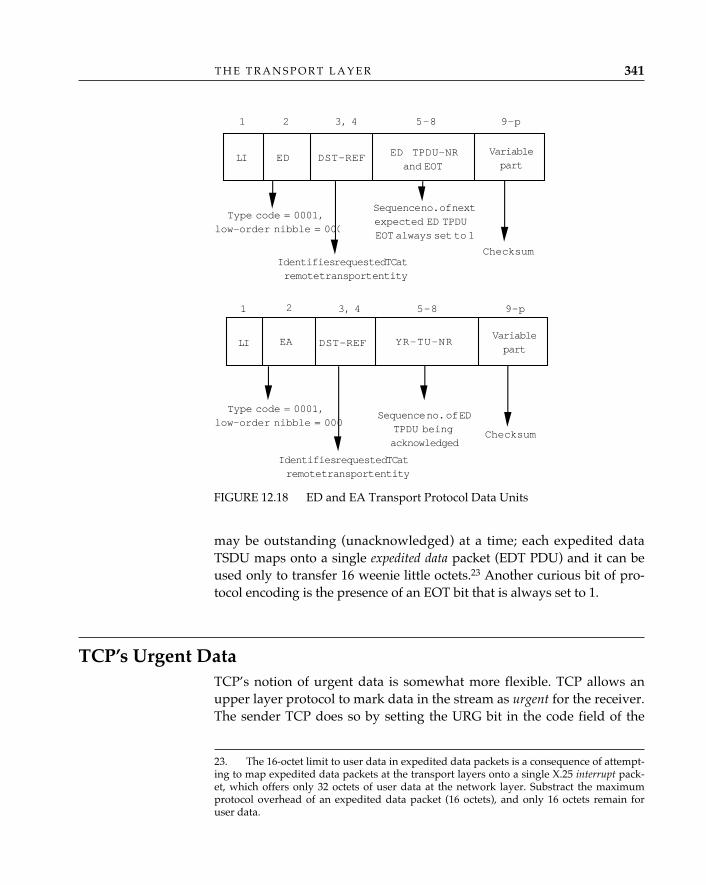
T H E T R A N S P O R T L A Y E R 341
may be outstanding (unacknowledged) at a time; each expedited dataTSDU maps onto a single expedited data packet (EDT PDU) and it can beused only to transfer 16 weenie little octets.23 Another curious bit of pro-tocol encoding is the presence of an EOT bit that is always set to 1.
TCP’s Urgent DataTCP’s notion of urgent data is somewhat more flexible. TCP allows anupper layer protocol to mark data in the stream as urgent for the receiver.The sender TCP does so by setting the URG bit in the code field of the
23. The 16-octet limit to user data in expedited data packets is a consequence of attempt-ing to map expedited data packets at the transport layers onto a single X.25 interrupt pack-et, which offers only 32 octets of user data at the network layer. Substract the maximumprotocol overhead of an expedited data packet (16 octets), and only 16 octets remain foruser data.
FIGURE 12.18 ED and EA Transport Protocol Data Units
LI ED DST-REF
Type code = 0001,low-order nibble = 000
1 2 3, 4 5–8 9–p
ED TPDU-NRand EOT
Identifies requested TC atremote transport entity
Variablepart
Sequence no. of nextexpected ED TPDUEOT always set to 1
Checksum
LI EA DST-REF
Type code = 0001,low-order nibble = 000
1 2 3, 4 5–8 9–p
YR-TU-NR
Identifies requested TC atremote transport entity
Sequence no. of EDTPDU beingacknowledged
Checksum
Variablepart
O P E N S Y S T E M S N E T W O R K I N G : T C P / I P A N D O S I342
TCP segment to 1, indicating that the URGENT field is significant. Thevalue of the URGENT field represents the number of priority deliveryoctets in this TCP segment (and perhaps in subsequent segments, if thenumber of octets in this segment is less than the value of the currentfield). This value is added to the segment sequence number to assist thereceiver TCP in identifying the last octet of urgent data. When the TCPsegment containing the URG bit arrives, the receiver TCP notifies theupper-layer protocol that urgent data are coming. Although not explicit-ly stated in RFC 793, it is assumed that the upper-layer protocol willbegin processing the urgent data; when the last octet of urgent dataarrives, the receiving TCP delivers the urgent data in the TCP segmentand notifies the upper-layer protocol that normal data transfer hasresumed. (It has been suggested that the urgent data capability is rough-ly equivalent to the session layer’s activity interrupt or capability data ser-vices. Some say this is a stretch.)
Timers and Open Transport ProtocolsThe most fundamental thing you can say about TP4 and TCP is that theyare timer-based: to operate correctly, both protocols rely on the certaintythat either an expected event will occur or a timer will expire. This char-acteristic is responsible for the robustness and flexibility of both of theseprotocols. The dependence on timers, however, means that the perfor-mance of TP4 or TCP is highly sensitive to the choice of timer values andto the way in which the values of different timers are related. It’s not ter-ribly difficult to choose reasonably good (initial) timer values or to buildimplementations that can dynamically adjust them, but the consequencesof choosing bad values, or building implementations that either cannotadapt or adapt inappropriately, are much more serious with TP4 andTCP than they are with protocols that do not depend as heavily ontimers.
The OSI transport protocol specification provides rudimentaryguidelines for establishing initial values for some of the many timers thattransport class 4 relies on for correct operation. If network-service behav-ior were uniform and stable, these guidelines might be sufficient. Unfor-tunately, the behavior of real-world networks is anything but uniformand stable. The practice of adjusting timer values to react correctly tochange in the behavior of networks is fundamental to correct and effi-cient transport implementations, be they OSI TP4 or TCP. What must betaken into consideration for many of these timers is described in a gener-
al way in the following subsections and is, for the most part, applicableto all retransmission and timer-based transport protocols.
Almost every TP4 packet (or TCP segment) must be either explicitly orimplicitly acknowledged. When a transport packet is first assembled andtransmitted, it is associated with a retransmission timer. If the expectedacknowledgment of the packet is not received before the timer expires,the packet is retransmitted and the timer is restarted (using either thesame or a different value for the time-out period); when the acknowledg-ment is received, the timer is canceled. Until the acknowledgment isreceived (or the transmission attempt is abandoned after “too many re-tries”), the sending system must retain enough information to be able toretransmit the original packet if necessary. Dealing with timers andtimer-generated events and holding information about packets for someperiod after they have been sent represent a significant load on theresources of a TP4 or TCP-based system. One of the most importantgoals of an efficient transport protocol implementation is therefore tominimize this overhead.
The basic problem with retransmission timers is choosing the righttime-out interval. An overly sensitive timer will cause the unnecessaryretransmission—duplication—of packets that were in fact received andacknowledged correctly; a sluggish timer will respond too slowly to theactual loss of a packet or its acknowledgment, increasing the delay asso-ciated with error detection and recovery. Ideally, a retransmission timershould expire only when it is actually the case that a packet or its ac-knowledgment has been lost or discarded. In practice, however, there isno way to be certain whether or not this has happened—that’s why thetimers are there.
The realistic goal is to pick (or dynamically approach) a time-outinterval that allows the protocol to recover quickly when a packet hasbeen lost (the timer value must not be too large) but reduces below someacceptable threshold the number of occasions on which a packet that wasin fact correctly received is retransmitted because the acknowledgmentdid not arrive before the expiration of the time-out interval (the timervalue must not be too small). In any environment in which the loss orcorruption of packets is not a rare occurrence, the performance of TP4and TCP is extremely sensitive to these timer values.
The internet over which TP4 and TCP operates may contain pathswith very different delay and throughput characteristics, which maychange dramatically during the lifetime of a transport connection, andthe timer-based behavior of the transport implementation at the other
T H E T R A N S P O R T L A Y E R 343
RetransmissionTimer
end of a transport connection cannot be completely predetermined. Be-cause of this variability, one cannot simply pick an “average” value forany retransmission timer (except in very limited, static configurations);there will always be configurations in which the protocol will not operateat all with such a static value, much less operate efficiently. These timersmust adapt dynamically to the actual, observed (or inferred) delay char-acteristics of each individual transport connection.
The timer-value problem has two parts. To maximize performance,the interval between the initial transmission of a packet and its firstretransmission should be tuned as finely as possible, with an adaptivegranularity small enough to keep the value close to its theoretical ideal.To ensure that the protocol will nevertheless operate correctly when theattempt to maximize performance leads to the choice of a much-too-smallinitial timer value for the connection-establishment phase and to allow itto cope with sudden, relatively large transient or persistent changes inend-to-end delay during the data-transfer phase, the interval must beincreased for the second and subsequent retransmissions (when neces-sary) in such a way that a sufficiently large interval is allowed to expirebefore the transmission attempt is deliberately abandoned (“too manyretries”).
If it were possible to periodically measure the actual end-to-end delaybetween two transport connection endpoints, the corresponding retrans-mission timer values could be adjusted up or down accordingly. Unfor-tunately, TP4’s normal data packets and their acknowledgments cannotalways be used for delay measurement, since a single acknowledgmentpacket can acknowledge more than one data packet, and the use of aselective acknowledgment strategy by the receiver can artificially skewround-trip delay measurements. TP4 expedited data packets, which mustbe acknowledged immediately and individually, could be used for thispurpose, but the expedited data option is not always selected, and evenwhen it is, there is no guarantee that expedited data will flow regularlyenough (or in some cases, even over the same path) to provide the neces-sary dynamic delay information.
Although it is not feasible to obtain a direct measurement of end-to-end delay, the first part of the timer-value problem can be solved suc-cessfully by using a trial-and-error technique that adjusts the timer valuebased on observed retransmission behavior: crank the retransmissiontime-out interval down until the number of retransmissions per measure-ment interval starts to climb and then gently bump the time-out valueback up until the number of retransmissions drops just below some
O P E N S Y S T E M S N E T W O R K I N G : T C P / I P A N D O S I344
Choosing andAdjustingRetransmissionTimer Values
T H E T R A N S P O R T L A Y E R 345
acceptable threshold. When the number of retransmissions rises abovethe threshold, the retransmission interval is increased; when it dropsbelow the threshold, the interval is decreased. The goal is to maintain anequilibrium just below the threshold.24
This “adaptive retransmission” scheme assumes that “false” re-transmissions caused by a too-short retransmission time-out interval canbe distinguished from “real” retransmissions caused by the actual loss ofdata packets—that when the retransmission interval is reduced below acertain threshold, the resulting increase in the number of “false” retrans-missions will be detectable against the fluctuating background of “real”retransmissions. Since there is no objective way to determine whetherany individual retransmission is “real” or “false,” this scheme dependson recognizing patterns in the observed retransmission behavior that canbe related to deliberate adjustments of the retransmission time-out inter-val. The basic technique, described earlier, is simply to raise the time-outvalue when the number of retransmissions increases and lower it whenthe number of retransmissions decreases, in an attempt to keep the num-ber of retransmissions at some “optimal” level (the threshold).
For most real-world configurations, this basic technique is muchtoo simplistic. It works only if changes in round-trip delay are the onlysignificant cause of changes in the number of retransmissions per mea-surement interval; the “threshold” number of ”real” retransmissionsmust be known in advance and must not change significantly. Evenwhen these conditions are met, the retransmission timer value will oscil-late whether or not the retransmission behavior changes, unless a longi-tudinal damping function is used to stabilize it. There are a number ofways to improve the basic adaptive retransmission scheme. A smooth-ing function that accounts for recent history (one or two measurementintervals back) can be used to damp oscillation of the time-out valuearound the threshold. A simple first-order smoothing function mightoperate to ensure that the time-out value is adjusted only when a changein retransmission behavior has persisted for two or more consecutivemeasurement intervals. A second-order function (which accounts forchanges in the rate of change of the number of retransmissions) can beused to damp oscillations even further, depending on how widely thenumber of “real” retransmissions is expected to fluctuate and on howfirmly these oscillations must be damped to provide acceptable perfor-
24. Although they are discussed separately in this chapter, the dynamic adjustment ofretransmission timers and the sliding window flow-control strategy (introduced earlier)will be closely coupled in any actual transport protocol implementation.
O P E N S Y S T E M S N E T W O R K I N G : T C P / I P A N D O S I346
mance. No damping function, however, can prevent performance-killinginflation of the re-transmission time-out interval or of the “threshold”number of retransmissions that are interpreted as “real” (and thereforeacceptable).
Consider, for example, the following scenario. A change in the char-acteristics of the end-to-end path over which packets are flowing causesan increase in the number of packets that are lost and/or corrupted; thiscauses a corresponding increase in the number of packets that must beretransmitted. These are “real” retransmissions, but neither of the trans-port protocol machines involved has any way of knowing this; as far asthey can tell, the observed increase in the number of retransmissionsmight just as well be caused by premature expiration of the re-transmis-sion timer due to an increase in the end-to-end transit delay. If this condi-tion persists, the retransmission time-out will be adjusted upward untilthe number of retransmissions per measurement interval stops increas-ing (if the condition disappears fast enough, and the number of retrans-missions drops back to its former level within the granularity of thedamping function, the retransmission time-out will not be changed). Theincrease in the number of retransmissions had nothing to do with thevalue of the retransmission timer, but the adaptive retransmission algo-rithm thinks that its action in raising the time-out value is responsible forhalting the increase in the number of retransmissions (because when thetime-out interval was raised, the increase in the number of retransmis-sions stopped—Piaget would love this algorithm). If the algorithm’sanalysis goes no further than this, the time-out interval will stabilize at anew (higher) value and will be driven back down only if the number ofretransmissions starts to decline. Just when efficient retransmissionbehavior is most important (to minimize the adverse effects of theincrease in the number of lost and/or corrupted packets), the retransmis-sion time-out interval is inflated, increasing the time it takes the protocolto recover from errors. This is not good.
In principle, the retransmission time-out interval should be adjustedonly to account for changes in transit delay; changing the time-out inter-val will not affect the number of retransmissions that are due to othercauses (such as a change in the number of lost or corrupted packets). Butbecause it is not possible to distinguish “real” retransmissions (due toloss and/or corruption of packets) from “false” ones (due to prematureretransmission timer expiration, caused by a mismatch between the time-out value and the actual end-to-end transit delay), the inflation justdescribed cannot be prevented. It can, however, be corrected after it hasoccurred by making the basic adaptive retransmission algorithm more
T H E T R A N S P O R T L A Y E R 347
sophisticated. When the number of retransmissions per measurementinterval changes spontaneously, the algorithm has no choice but tochange the retransmission timer value accordingly (damping small oscil-lations). When the number of retransmissions is stable, however, thealgorithm can deliberately alter the retransmission time-out: increase itto see whether the number drops or decrease it to see whether the num-ber rises. By periodically challenging a stable timer value, the algorithmcan correct inflation of the time-out interval and can also correct a too-short time-out interval that is producing an unnecessarily high (but sta-ble, and therefore unprovocative) number of retransmissions.
Adapting retransmission timer values to cope with variable delay iscertainly not unique to OSI; it has been observed and managed in TCPnetworks for many years. In RFC 793, it is recommended that theretransmission time-out be based on round-trip time (RTT), which is com-puted by recording the time elapsed between sending a data segmentand receiving the corresponding acknowledgment and by sampling fre-quently. The algorithm used to compute the round-trip time is:
smoothedRoundTripTime = (å* oldRoundTripTime) + ((1 – å)*newRoundTripTime)
where å, a weighting factor, is selected such that 0 < å < 1.A small å responds to delay quickly; a large å, slowly. The time-out
value should be greater than the round-trip time but within reason; forexample:
time-out = minimum(upperBound,ß*smoothedRoundTripTime)
where ß, a delay variance factor, is selected such that 1.3 < ß < 2.
Some deficiences have been identified and corrected in this initialalgorithm. Karn and Partridge (1987) observed that retransmitted seg-ments cause ambiguities in the round-trip time computation; specifically,if the sender cannot determine whether the acknowledgment corre-sponds to an original data packet or a retransmission, it cannot deter-mine the correct round-trip time for that packet. The Karn/Partridgealgorithm computes the round-trip time only for packets that are notretransmitted and increases the retransmission timer by a multiplicativefactor (2 is suggested) each time a segment is retransmitted.
Further study showed that limiting ß in the manner described inRFC 793 will fail if delays vary widely, and Jacobson (1988) proposesthat estimates for both the average round-trip time and the varianceshould be provided and that the estimated variance be used in place of ß.These algorithms work as well in TP4 implementations as in TCP imple-mentations.
During OSI transport connection establishment, two timers govern there-transmission of the connect request and connect confirm packets.These packets are sent out before there has been any opportunity toobserve or infer the end-to-end round-trip delay; and in general, no reli-able “pregenerated” information about the probable delay to a given des-tination is available (although when it is, it can be used to guide theselection of initial CR and CC timer values). The end-to-end delay over asingle subnetwork (link) might be anywhere from 1 or 2 milliseconds (fora LAN) to 250 milliseconds (for a satellite link), and there could be almostany number of these links, in various combinations, in the actual end-to-end path. The round-trip delay also includes processing time in the twoend systems and in an unpredictable number of intermediate (gateway)systems. Under these circumstances, the probability of correctly guessingthe optimal timer value (or even something acceptably close to it) is verysmall.
There is an alternative to simply picking a timer value at random.As long as the retransmission interval is increased substantially for sec-ond and subsequent retransmissions (when necessary), a very small ini-tial time-out value (on the order of 250–500 milliseconds) can be used.This will give good performance when the actual delay is small (and con-figurations with small end-to-end delay are precisely the ones in whichhigh performance is likely to be most important). The possible unneces-sary retransmission of one or more connect request or connect confirmpackets when the actual delay is larger than the small initial value chosenfor the timer is usually acceptable, occurring as it does only during theconnection-establishment phase. Incrementally backing off the retrans-mission timer each time it expires (using, for example, a 500-millisecondincrement) and setting the “maximum number of retries” threshold fairlyhigh (at 15, for example) can ensure that very few (if any) connection-establishment attempts are abandoned (timed out) prematurely (see“Backing Off for Subsequent Retransmissions,” later in this section).
A simple way to pick a starting value for an adaptive data packet re-transmission scheme is to measure, during the connection-establishmentphase, the delay between sending a connect request and receiving thecorresponding connect confirm (or at the other end, between sending aconnect confirm and receiving the corresponding acknowledgment orfirst data packet). Because the connect request and/or connect confirmpackets may be retransmitted, and because processing delays associatedwith connection establishment are usually greater than those associatedwith normal data flow, this value cannot be used as a constant for the
O P E N S Y S T E M S N E T W O R K I N G : T C P / I P A N D O S I348
Connection-EstablishmentTimers
DataRetransmissionTimer Value
data packet retransmission time-out value; it is likely to be accurateenough, however, to ensure that an adaptive retransmission algorithmquickly converges on a satisfactory value. An adaptive retransmissionscheme is most useful either when no prior information about the round-trip delay variance is available or when the available information sug-gests that the delay variance could be large. When it is possible to expectthat the delay variance will be relatively small, better performance can beobtained from a well-chosen constant value for the data retransmissiontime-out value, based on a slight overestimate of the expected maximumround-trip delay (this is especially true for operation of TP4 over a net-work connection). The retransmission timer associated with expediteddata packet can be managed in the same way as the timer associatedwith normal data packets.
No matter how cleverly the initial value for a retransmission timer ischosen, there will be circumstances in which the timer expires, the asso-ciated packet is retransmitted, and the timer must be reset. A simpleapproach to choosing a new timer value is to reuse the initial value. Thisapproach will produce a series of retransmissions at evenly spaced inter-vals, which will terminate when the retransmission timer is canceled bythe arrival of an appropriate acknowledgment or the maximum numberof retries is reached. If the initial time-out value is not too far off themark, or the maximum number of retries parameter is very large, thisapproach will work. If the initial time-out value is much too short, how-ever, either the maximum number of retries will be exhausted before anyacknowledgment has had time to arrive, or a large number of unneces-sarily retransmitted packets will be pumped out of the sending systembefore the acknowledgment arrives. In the former case, the transportconnection or connection-establishment attempt will be aborted whenthe sender’s give-up timer expires (the value of the give-up timerdepends on the retransmission timer value and the maximum number ofretries, as discussed in the following subsection). In the latter case, adap-tation of the initial time-out interval (as described earlier) will eventuallycorrect the problem for data packets, but the situation will persist forconnect request and connect confirm packets, for which no adaptiveadjustment of the retransmission timer value is possible.
Using an equal-interval approach to retransmission constrains thechoice of an initial retransmission timer value: if the two pathological sit-uations just described are to be avoided, the time-out interval cannot bereduced below a certain “safety threshold.” In configurations in whichthe mean transit delay is low but the delay variance is relatively high,
T H E T R A N S P O R T L A Y E R 349
Backing Off forSubsequentRetransmissions
O P E N S Y S T E M S N E T W O R K I N G : T C P / I P A N D O S I350
this constraint limits the effective performance of the protocol.25
An algorithm that backs off geometrically for each retransmissionrather than linearly eliminates this constraint. When a packet is firsttransmitted, the corresponding retransmission timer is set to the appro-priate initial value for that packet (which is either a constant, for connectrequest and connect confirm packets, or a dynamic value determined byan adaptive retransmission scheme, for data packets). If this timer ex-pires, the packet is retransmitted, and the retransmission timer is set to avalue that is the sum of the initial value and a fixed increment (the “back-off” increment). If this timer expires, the packet is again retransmitted,and the retransmission timer is set to a value that is the sum of the initialvalue and twice the back-off increment. This continues until the timer iscanceled by the arrival of a suitable acknowledgment (or the transmis-sion attempt is abandoned after “too many retries”). Each retransmissioninterval is therefore longer than the one before it. When the retransmis-sion interval is increased in this way after each retransmission, the partialsums that represent the accumulated time since the first transmission of apacket grow geometrically rather than linearly. This allows a transportprotocol to recover quickly from the choice of a too-small initial timervalue, without falling into either of the two traps described earlier. Theinitial retransmission interval can be made as small as necessary toachieve good performance, relying on the geometric algorithm to backthe value off safely if something goes wrong.
For the algorithm just described, the aggregate retransmission timeis a function of the constant parameters for the maximum number ofretries and the back-off increment. Without making the function too com-plicated, we can also allow the first-retransmission interval to be differ-ent from the back-off increment. Letting x be the maximum number ofretries, y the interval between the initial transmission of a data packetand its first retransmission, and z the fixed increment by which theretransmission time is increased for each retransmission after the first,we obtain the following formula:
aggregate = y(x + 1) + [zx(x + 1)/2]
Note: The value of y for data packet retransmission will changedynamically if an adaptive retransmission scheme is used.
As an example, assume an implementation that has chosen x = 5,
25. If the delay variance is low, the probability of either of the two pathological condi-tions occurring is also low, and the “safety threshold” can be set as low as necessary toavoid this performance limit.
y = 500 milliseconds, and z = 1 second. At most, 18 seconds will elapsebetween the first transmission of a packet and the expiration of the lastretransmission timer (“too many retries”). This value sets a lower boundon the value of the give-up timer.
Associated with each OSI transport connection is a “give-up” timer,which is started (or restarted) whenever the first incarnation of a datapacket is sent out (that is, it is not reset when a data packet is retransmit-ted, as is the data packet retransmission timer). Whenever an acknowl-edgment covering all outstanding data packets is received, the give-uptimer is canceled.26
The give-up timer establishes an upper bound on the amount oftime that can elapse between the first transmission of a packet and thereceipt of an acknowledgment that covers that transport protocol dataunit. The expectation of an acknowledgment can remain unfulfilled forno more than the give-up time-out interval before TP4 decides that itspeer is either dead, disabled, or malfunctioning; if the give-up timerexpires, the corresponding transport connection is torn down.
The give-up timer value should be large enough so that it includesany reasonable combination of end-to-end processing and transmissiondelays (including the maximum number of retransmissions). It must,however, be less than the value of the reference timer in all other trans-port protocol machines with which a given implementation will commu-nicate, to ensure that no retransmission can occur after a remote peer hasdecided that it is safe to reuse a transport connection reference (see“Reference Timer,” later in this section). When, for whatever reason, atransport protocol machine stops receiving the packets that are beingsent by its peer, the operation of the give-up timer in the sending systemensures that the sender will not inject a packet into the pipe that might (ifthe pipe eventually clears) arrive at the receiver after the expiration ofthe receiver’s reference timer.
The value of the give-up timer must be greater than the maximumaggregate data retransmission time and less than the value of the referencetimer in all other transport systems. In the example described in the previoussubsection, the aggregate data retransmission time is 18 seconds. A typicalreference timer value (again, see “Reference Timer”) is 100 seconds. Withinthese bounds, a reasonable give-up timer value would be 40 seconds.
T H E T R A N S P O R T L A Y E R 351
Give-Up Timer
26. Whenever the expedited data option is implemented, there are actually two separategive-up timers: one for normal data TPDUs and one for expedited data TPDUs. They oper-ate independently, but in the same way.
O P E N S Y S T E M S N E T W O R K I N G : T C P / I P A N D O S I352
On every transport connection, each of the two transport protocolmachines involved must regularly demonstrate both existence and sanityto its peer, by sending a correctly formed packet. This is true whether ornot the peers have any user data to exchange; in the absence of data flow,the peers exchange acknowledgment packets in response to the expira-tion of their window timers (discussed later in this section). The protocoldepends on this “I’m OK, you’re OK” form of phatic communion tomaintain connectivity and to detect its loss. Silence, therefore, is anabnormal (and eventually fatal) condition.
The inactivity timer detects silence. It is started when a connectionis first established and is reset whenever any valid packet is received forthat connection. It expires, therefore, only when a period of silence haspersisted for long enough that the local transport protocol machine mustassume that its peer has either died or become disabled. The expiration ofan inactivity timer results in termination of the corresponding transportconnection.
The value of the inactivity timer is chosen to reflect the most appro-priate compromise between the desire to keep a sick transport connectionopen as long as there is a reasonable hope that it can be revived (withinthe “quality of service” constraints, if any, specified by the transportuser) and the desire to recognize a genuinely dead connection as quicklyas possible. Since the value of the window timer is directly related to thevalue of the inactivity timer in all other transport implementations, theinactivity timer value must be chosen carefully.
Whenever there is two-way data traffic on a transport connection, thecorresponding flow of acknowledgments in both directions ensures thatboth transport machines have up-to-date window (flow-control) infor-mation. If data packets flow in only one direction, or if there are no datapackets flowing in either direction (there are no user data to send, or oneor both of the transport protocol machines has closed its receive win-dow), this information must be exchanged by some other mechanism.
The window timer generates a flow of acknowledgment packetsthat depends only on the existence and health of the sending transportprotocol machine; even when there is no need to acknowledge a datapacket, an acknowledgment packet will be sent at regular intervals as thewindow timer expires. This serves two essential purposes: it prevents theremote peer’s inactivity timer from expiring in response to a long stretchof silence (that is, it convinces the remote peer that its partner is still aliveand well), and it conveys up-to-date window information (credit), whichmay change whether or not there is current data traffic. To understand
Inactivity Timer
Window Timer
the importance of the latter function, consider that when a receive win-dow closes, a potential sender—which can’t send into a closed window,of course, and therefore will not be getting new acknowledgments as aresult of having sent new data—will never learn that the receive windowhas reopened unless the receiver sends an “unprovoked” acknowledg-ment containing a new credit.
Because one of the roles of the window timer is to prevent the expi-ration of the inactivity timer in a remote peer, its value must be chosenwith respect to the value of the inactivity timer in other transport proto-col machines. Since acknowledgments, like other packets, can be lost, thevalue of the inactivity timer is usually chosen to allow one or two “win-dow” acknowledgments to be generated and lost without risking expira-tion of the inactivity timer. A typical value for the window timer allowsfor three window time-outs within an interval that is slightly smallerthan the inactivity time-out interval.
When an OSI transport connection is closed (normally or abnormally), areference timer is started; until it expires, the local connection referencenumber that was used for the old connection cannot be reused for a newone. The reference timer ensures that a new connection based on a previ-ously used connection reference number cannot be opened until it is cer-tain that all packets generated during the lifetime of the old connectionhave disappeared.
The reference timer is designed to cope with situations such as theone described in the following scenario. Two transport protocol ma-chines establish a transport connection and start exchanging data pack-ets. At some point, congestion in the path between the two transportpeers causes a data packet (and its subsequent retransmissions) to bedelayed long enough for the give-up timer in the sending transport pro-tocol machine to expire, terminating the connection. Eventually, however,the congestion clears, and the packet (and/or one or more of its retrans-missions) arrives at its destination. If the reference number that was usedfor the original transport connection has been reused in the interim toestablish a new connection, the late-arriving packet could be (mis)inter-preted as belonging to the new connection.
It is important to note that no value of the reference timer is largeenough to guarantee, by itself, that the confusion just described cannotarise. It is also necessary for the underlying internetwork protocol tooperate in such a way that internetwork protocol data units, which carrypackets, are discarded after a specific “packet lifetime” is exceeded. TheOSI connectionless network protocol includes this function (see Chapter
T H E T R A N S P O R T L A Y E R 353
Reference Timer
O P E N S Y S T E M S N E T W O R K I N G : T C P / I P A N D O S I354
13). A local system-management function must ensure that the referencetime-out value associated with each transport connection is greater thanthe packet lifetime specified in the network protocol packets that carrydata for that transport connection.
Approximately 216 reference numbers are available for use withtransport connection endpoints associated with a single NSAP (network)address. Most transport implementations—assuming that even under themost extreme circumstances, it will take at least a couple of millisecondsto set up and tear down a transport connection—will use a value of about27 or 28 seconds for the reference timer. If it is very important to recoverthe local system resources dedicated to a transport connection quicklyafter the connection is closed, a smaller value will be used. A value of 100seconds is about the lowest that can be used safely in a general-purposeimplementation.
Connection Release (Connection Refusal) in the OSI TransportProtocol
There are actually two circumstances that dictate the release of an OSItransport connection. The first, connection refusal, occurs when the calledtransport entity cannot satisfy one or more of the conditions of transportconnection establishment conveyed in the connection request packet, orwhen the connect request packet received is in error. To refuse a trans-port connection, the called transport entity composes and returns a dis-connect request packet (DR TPDU) (Figure 12.19) containing the reason forrefusing the connection. The expected reasons for refusing a connectionare identified (negotiation failed, reference overflow, transport serviceaccess point address unknown), and several more creative reasons forrefusing a connection are provided (congestion at transport serviceaccess point, session entity not attached to transport service access point).
If the connection is refused due to an inability to parse the connectrequest packet, the called transport entity returns an error packet (ERTPDU), indicating the reason for refusal. This form of connection refusaltypically reflects an error in implementation (e.g., an invalid parameteror parameter value was encountered) or detection of a bit-level error as aresult of computing the checksum on the connect request packet. All ofthe octets of the connect request packet that caused the rejection arereturned in the variable part of the error packet.
Connection release is an extremely mundane phase of operation. To
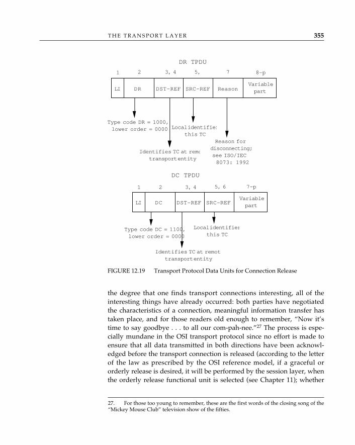
T H E T R A N S P O R T L A Y E R 355
the degree that one finds transport connections interesting, all of theinteresting things have already occurred: both parties have negotiatedthe characteristics of a connection, meaningful information transfer hastaken place, and for those readers old enough to remember, “Now it’stime to say goodbye . . . to all our com-pah-nee.”27 The process is espe-cially mundane in the OSI transport protocol since no effort is made toensure that all data transmitted in both directions have been acknowl-edged before the transport connection is released (according to the letterof the law as prescribed by the OSI reference model, if a graceful ororderly release is desired, it will be performed by the session layer, whenthe orderly release functional unit is selected (see Chapter 11); whether
27. For those too young to remember, these are the first words of the closing song of the“Mickey Mouse Club” television show of the fifties.
FIGURE 12.19 Transport Protocol Data Units for Connection Release
LI DR DST-REF SRC-REF ReasonVariablepart
1 2 3, 4 5, 7 8–p
Identifies TC at remotransport entity
Type code DR = 1000,lower order = 0000 Local identifier
this TCReason for
disconnecting;see ISO/IEC8073: 1992
DR TPDU
LI DC DST-REF SRC-REFVariablepart
1 2 3, 4 5, 6 7–p
Identifies TC at remottransport entity
Type code DC = 1100,lower order = 0000
Local identifierthis TC
DC TPDU
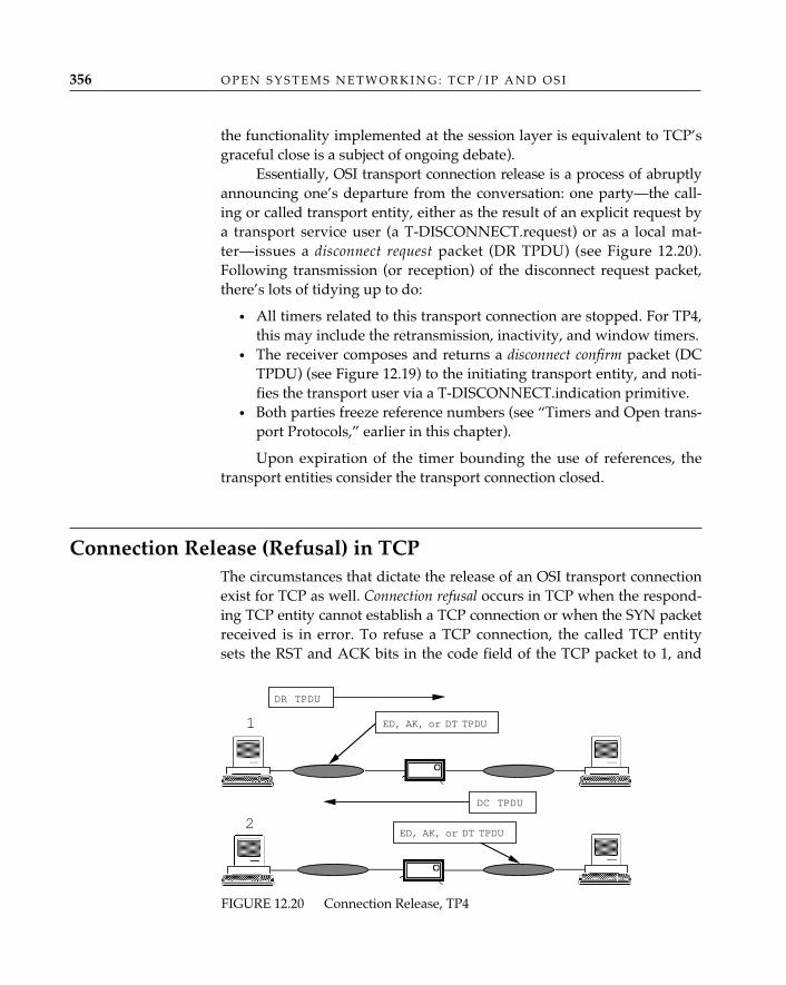
O P E N S Y S T E M S N E T W O R K I N G : T C P / I P A N D O S I356
the functionality implemented at the session layer is equivalent to TCP’sgraceful close is a subject of ongoing debate).
Essentially, OSI transport connection release is a process of abruptlyannouncing one’s departure from the conversation: one party—the call-ing or called transport entity, either as the result of an explicit request bya transport service user (a T-DISCONNECT.request) or as a local mat-ter—issues a disconnect request packet (DR TPDU) (see Figure 12.20).Following transmission (or reception) of the disconnect request packet,there’s lots of tidying up to do:
• All timers related to this transport connection are stopped. For TP4,this may include the retransmission, inactivity, and window timers.
• The receiver composes and returns a disconnect confirm packet (DCTPDU) (see Figure 12.19) to the initiating transport entity, and noti-fies the transport user via a T-DISCONNECT.indication primitive.
• Both parties freeze reference numbers (see “Timers and Open trans-port Protocols,” earlier in this chapter).
Upon expiration of the timer bounding the use of references, thetransport entities consider the transport connection closed.
Connection Release (Refusal) in TCPThe circumstances that dictate the release of an OSI transport connectionexist for TCP as well. Connection refusal occurs in TCP when the respond-ing TCP entity cannot establish a TCP connection or when the SYN packetreceived is in error. To refuse a TCP connection, the called TCP entitysets the RST and ACK bits in the code field of the TCP packet to 1, and
FIGURE 12.20 Connection Release, TP4
DR TPDU
DC TPDU
ED, AK, or DT TPDU
ED, AK, or DT TPDU
2
1
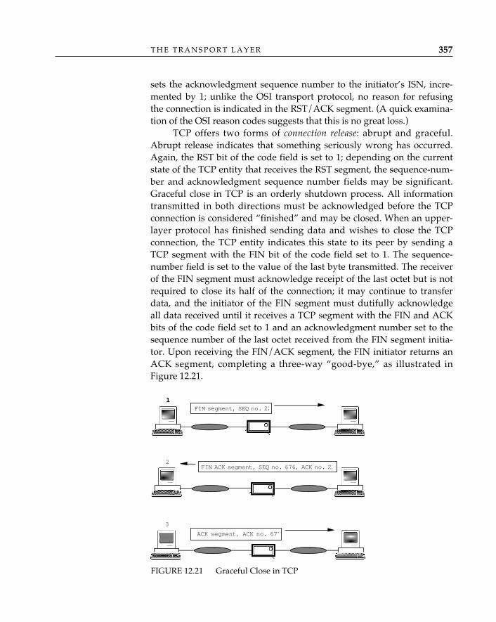
T H E T R A N S P O R T L A Y E R 357
sets the acknowledgment sequence number to the initiator’s ISN, incre-mented by 1; unlike the OSI transport protocol, no reason for refusingthe connection is indicated in the RST/ACK segment. (A quick examina-tion of the OSI reason codes suggests that this is no great loss.)
TCP offers two forms of connection release: abrupt and graceful.Abrupt release indicates that something seriously wrong has occurred.Again, the RST bit of the code field is set to 1; depending on the currentstate of the TCP entity that receives the RST segment, the sequence-num-ber and acknowledgment sequence number fields may be significant.Graceful close in TCP is an orderly shutdown process. All informationtransmitted in both directions must be acknowledged before the TCPconnection is considered “finished” and may be closed. When an upper-layer protocol has finished sending data and wishes to close the TCPconnection, the TCP entity indicates this state to its peer by sending aTCP segment with the FIN bit of the code field set to 1. The sequence-number field is set to the value of the last byte transmitted. The receiverof the FIN segment must acknowledge receipt of the last octet but is notrequired to close its half of the connection; it may continue to transferdata, and the initiator of the FIN segment must dutifully acknowledgeall data received until it receives a TCP segment with the FIN and ACKbits of the code field set to 1 and an acknowledgment number set to thesequence number of the last octet received from the FIN segment initia-tor. Upon receiving the FIN/ACK segment, the FIN initiator returns anACK segment, completing a three-way “good-bye,” as illustrated inFigure 12.21.
FIGURE 12.21 Graceful Close in TCP
1FIN segment, SEQ no. 22
FIN ACK segment, SEQ no. 676, ACK no. 222
3
ACK segment, ACK no. 677
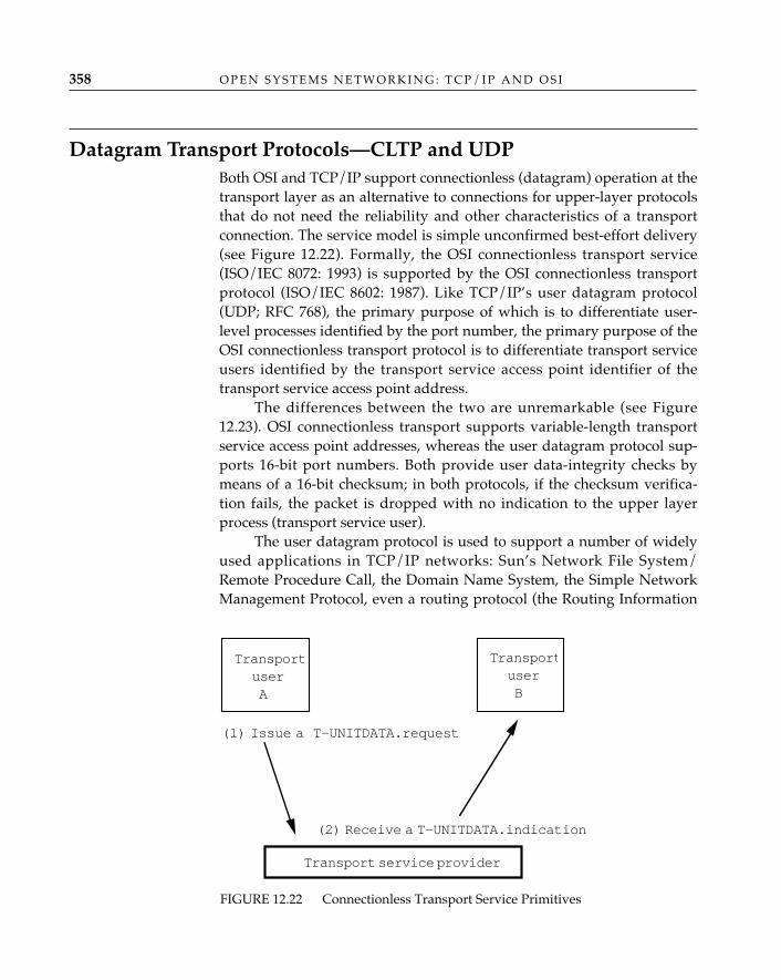
O P E N S Y S T E M S N E T W O R K I N G : T C P / I P A N D O S I358
Datagram Transport Protocols—CLTP and UDPBoth OSI and TCP/IP support connectionless (datagram) operation at thetransport layer as an alternative to connections for upper-layer protocolsthat do not need the reliability and other characteristics of a transportconnection. The service model is simple unconfirmed best-effort delivery(see Figure 12.22). Formally, the OSI connectionless transport service(ISO/IEC 8072: 1993) is supported by the OSI connectionless transportprotocol (ISO/IEC 8602: 1987). Like TCP/IP’s user datagram protocol(UDP; RFC 768), the primary purpose of which is to differentiate user-level processes identified by the port number, the primary purpose of theOSI connectionless transport protocol is to differentiate transport serviceusers identified by the transport service access point identifier of thetransport service access point address.
The differences between the two are unremarkable (see Figure12.23). OSI connectionless transport supports variable-length transportservice access point addresses, whereas the user datagram protocol sup-ports 16-bit port numbers. Both provide user data-integrity checks bymeans of a 16-bit checksum; in both protocols, if the checksum verifica-tion fails, the packet is dropped with no indication to the upper layerprocess (transport service user).
The user datagram protocol is used to support a number of widelyused applications in TCP/IP networks: Sun’s Network File System/Remote Procedure Call, the Domain Name System, the Simple NetworkManagement Protocol, even a routing protocol (the Routing Information
FIGURE 12.22 Connectionless Transport Service Primitives
TransportuserA
TransportuserB
Transport service provider
(2) Receive a T-UNITDATA.indication
(1) Issue a T-UNITDATA.request
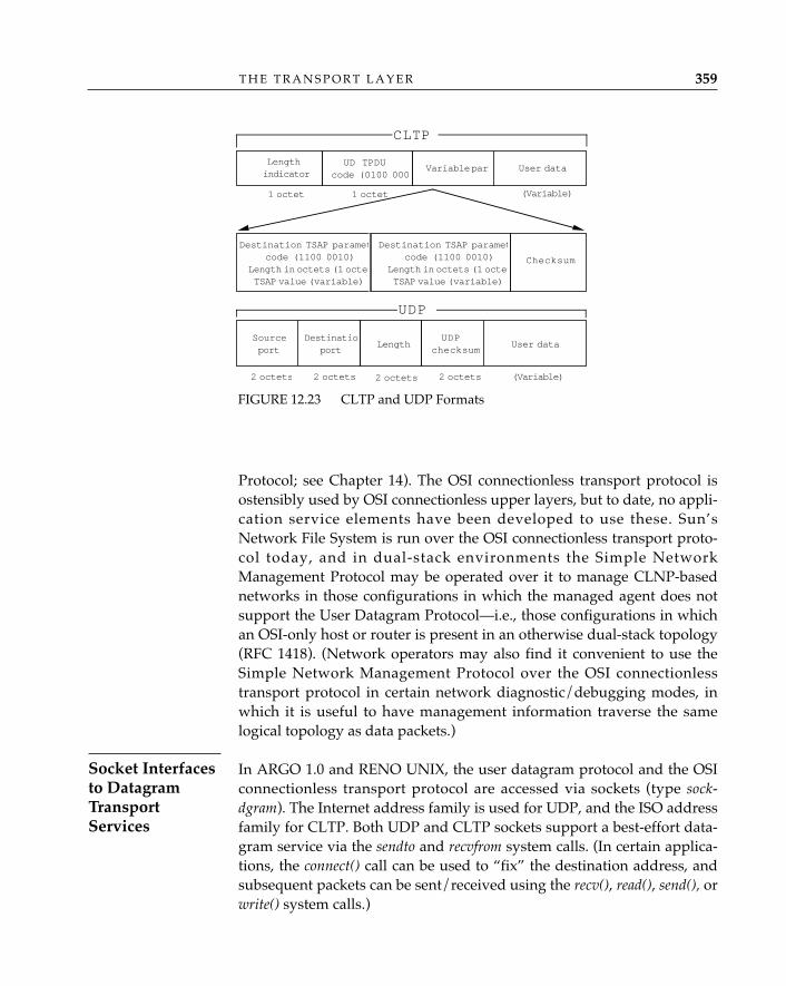
T H E T R A N S P O R T L A Y E R 359
Protocol; see Chapter 14). The OSI connectionless transport protocol isostensibly used by OSI connectionless upper layers, but to date, no appli-cation service elements have been developed to use these. Sun’sNetwork File System is run over the OSI connectionless transport proto-col today, and in dual-stack environments the Simple NetworkManagement Protocol may be operated over it to manage CLNP-basednetworks in those configurations in which the managed agent does notsupport the User Datagram Protocol—i.e., those configurations in whichan OSI-only host or router is present in an otherwise dual-stack topology(RFC 1418). (Network operators may also find it convenient to use theSimple Network Management Protocol over the OSI connectionlesstransport protocol in certain network diagnostic/debugging modes, inwhich it is useful to have management information traverse the samelogical topology as data packets.)
In ARGO 1.0 and RENO UNIX, the user datagram protocol and the OSIconnectionless transport protocol are accessed via sockets (type sock-dgram). The Internet address family is used for UDP, and the ISO addressfamily for CLTP. Both UDP and CLTP sockets support a best-effort data-gram service via the sendto and recvfrom system calls. (In certain applica-tions, the connect() call can be used to “fix” the destination address, andsubsequent packets can be sent/received using the recv(), read(), send(), orwrite() system calls.)
FIGURE 12.23 CLTP and UDP Formats
Checksum
Lengthindicator
UD TPDUcode (0100 000
Variable part User data
1 octet 1 octet (Variable)
Destination TSAP parametcode (1100 0010)
Length in octets (1 octetTSAP value (variable)
User data
(Variable)
UDPchecksum
Length
2 octets 2 octets
Destinationport
Sourceport
2 octets2 octets
Destination TSAP parametcode (1100 0010)
Length in octets (1 octetTSAP value (variable)
UDP
CLTP
Socket Interfacesto DatagramTransportServices
O P E N S Y S T E M S N E T W O R K I N G : T C P / I P A N D O S I360
ConclusionThe transport layer plays the same critical role in both the OSI andTCP/IP architectures: it defines the concept of “host” or “end system,” inwhich applications live, and distinguishes these end-user hosts from sys-tems that are concerned only with the “intermediate” functions (routing,relaying, switching, and transmission) of networking. As it is typicallydeployed at a real boundary between facilities belonging to end usersand facilities belonging to the network, transport is the host’s opportunityto ensure that its applications get the data pipe that they want, regardlessof what the network is prepared to provide. The OSI transport protocolfudges this a bit by defining classes 0 through 3 in such a way that theend-to-end reliability seen by applications in fact depends very much onwhat the network is able to provide; but class 4, and TCP, support a gen-uinely network-independent transport service, which can be provided asreliably over connectionless internets as over connection-oriented net-works. For applications that do not require the reliability of a transportconnection, OSI and TCP/IP provide connectionless (transport data-gram) alternatives as separate protocols.
Much has been written about the differences between TCP and theOSI class-4 transport protocol in an effort to prove that one or the other is“better.” There is ample fuel for this debate: TCP is octet-sequenced, TP4is packet-sequenced; TCP has graceful close, TP4 does not; TCP’s portnumbers are fixed at 16 bits, TP4’s are variable-length. The list is long,but it contains no “killer argument” in favor of either protocol. Readersinterested in pursuing this question will find a convincing argument forthe essential irrelevance of this “which is better?” debate in Chapin (1990).
Like all the other OSI layers, the network layer provides both connection-less and connection-oriented services. The upper layers and transportprovide these two types of service to satisfy a broad range of applicationand end-user needs. This is universally recognized as a “good thing.” Inthe network layer, the presence of two types of service is generally con-sidered to be a “bad thing.” The reason for this is simple: everythingabove the network layer is host-specific and can be tailored to suit a par-ticular application running among some set of mutually consenting hostswithout affecting the communications of other hosts using the sameinternetwork; the network layer, however, provides the fundamentalconnectivity without which no communication of any kind can takeplace among hosts. Most people agree that having one type of service atthe network layer would be preferable to having two; as always, though,the problem stems from having to decide which one.1
The TCP/IP architecture, which from the beginning was based onan “internetworking” model of the network layer,2 avoided this contro-versy entirely; the TCP/IP network layer is exclusively connectionless.3
13 THE NETWORK LAYER
361
1. There are people who attempt to justify a “diversity of needs” at the network layer,but their sense of what constitutes interoperability is quite different from ours.2. The best (and certainly the most succinct) description of the fundamental architec-tural premise of the TCP/IP network layer is the one that Vint Cerf uses to describe theTCP/IP internetworking model: “I P on everything.”3. The requirement to support new types of service in the Internet, such as real-timeservice for voice and video, may change the traditional “datagrams-only” model of theTCP/IP network layer. The new concept of a “flow,” which is neither a connection nordatagrams, promises to make the TCP/IP network layer a bit more complicated (but also abit more useful) in the near future (Partridge 1992).
The issues surrounding a “choose one” decision at the networklayer were of such a highly charged political, economic, and emotionalnature that convergence on a single networking solution for OSI was,and remains, a pipe dream. Compounding the problem, there is no gen-erally recognized way to interwork between connection-oriented andconnectionless networks. ISO/IEC 8648: 1987, Internal Organization of theNetwork Layer, does not provide a solution; however, demystifying itscontents does provide meaningful insight into the problem, so it is a logi-cal place to begin.
Architecture: The Internal Organization of the Network LayerIt is virtually impossible to understand the purpose and contents of theInternal Organization of the Network Layer standard without a historicalperspective. In the abstract, the OSI network layer provides the switchingfabric over which end systems communicate. The notion of a single, opennetworking environment for data is a powerful one, since it implies avery broad scale of connectivity. In fact, it is not hard to imagine (andeven easier to desire) an open data network that is as ubiquitous as thevoice network.
The postal, telephone, and telegraph (PTT) administrations of manynational governments4 have long been committed to standards as pro-cessed for telephony under the CCITT. A strong political incentive existedat the time of OSI network-layer standards development to institute asingle, uniform network service standard for data. Publicly, advocates ofthis network-centric view claimed that a single service, modeled after thevoice network, would scale well—the voice network certainly did. A frame-work for multiorganizational administration existed for nasty issues likeaddressing and interworking. Moreover, they continued, similar servicecharacteristics could be expected irrespective of the location of the sourceand target applications. Privately, these parties hoped that by bringingcomputer communications further under the administration of the PTTs,they would “contracept” further expansion of the private networkingoffered by large multinational computer vendors. By so doing, theyhoped to promote the interests of their native (especially European) com-
O P E N S Y S T E M S N E T W O R K I N G : T C P / I P A N D O S I362
4. Some countries, including the United States and the United Kingdom, do not have a sin-gle “national” public network agency. To accommodate these countries, the CCITT consid-ers that recognized private operating agencies (RPOAs), such as British Telecom and AT&T,have standing equivalent to the PTTs of countries with national public network agencies.

puter vendors and strengthen both their own domestic and internationalmarkets. In short, they hoped to expand the market for public network-ing services, helping their home computer companies in the process.
OSI network-layer development also began when data communica-tion was, by today’s standards, in its infancy. Turnkey remote job entryand terminal-to-mainframe communications were the principal applica-tions. Local area networks were fledgling and pricey technologies. On-premises terminal connectivity was achieved by a hodgepodge of largelyproprietary asynchronous “poll-select” technologies, and wide-areabandwidth was expensive, even for modest kilobit-rate services, soapplications (and end users) were made to tolerate delay. Compared toeven the smallest of today’s regional TCP/IP networks, private network-ing was a small-scale, predominantly mainframe-to-mainframe enter-prise, and the wide area network was the center of the universe.
When the price of local area network (LAN) technology dropped,the “public network is everything” paradigm was shattered forever. On-premises bandwidth was cheap and plentiful; applications and process-ing were distributed among large numbers of increasingly powerful yetsmaller computers, initially across local area networks, but soon acrosshigher-bandwidth wide area services. Thus, two paradigms for networkservice—local area network and wide area network—collided preciselyat the time of the development of standards for the OSI network layer.
Renegades from the community of local area network equipmentmanufacturers and consumers rose to challenge the network-centricview of the world. Unlike voice service, they argued, for which the ser-vice characteristics necessary to support the primary application (speech)have remained constant for a century, the characteristics of network ser-vices necessary for computer-to-computer communications vary widelyfrom application to application. Terminal access to remote computersrequires only low bandwidth and can tolerate delay, whereas networkedfile services like Sun’s Network File System (Sandberg 1988) require highbandwidth and low delay, but only for short periods or bursts. Otherapplications (electronic mail, file transfer) have requirements somewherebetween these extremes.
Applications also have varying requirements for data integrity, reli-ability in data transfer, and other characteristics. The local area networkproponents argued that true distributed applications needed LAN-likecharacteristics across a wide area. These can best be provided by adopt-ing the internetworking protocol concepts demonstrated in the DefenseAdvanced Research Projects Agency experiments and deployed in pro-prietary architectures such as Xerox Network Systems (XNS), Digital
T H E N E T W O R K L A Y E R 363
Network Architecture (DNA), and Burroughs Network Architecture(BNA). Privately, vendors of host computers, routers, and other comput-er-communications equipment hoped to use OSI as a means of penetrat-ing hitherto single-vendor “closed-shop” environments held by theindustry giants: in an open platform, smaller, nimbler manufacturerscould compete for market share by specializing rather than offering acomprehensive micro-to-mainframe line of computers. The industrygiants contributed their proprietary solutions to universal networkingproblems in an attempt to ease the inevitable transition. Computer ven-dors big and small—hereafter referred to as host-centrics—had a commonobjective: they wanted a solution that would enable them to sell morecommunications as well as host equipment.
The OSI network layer is thus where net-worlds collide. Two substan-tially different views of the way in which network service should be pro-vided had been defined. Champions for both causes stepped forward,lines were drawn in the sand, and battles ensued. The Internal Organiza-tion of the Network Layer was to become the demilitarized zone of the”police action“ initiated to unify the OSI network layer. Within this stan-dard, it was expected that differences would be reconciled and a frame-work for interconnectivity would be defined.
The Internal Organization of the Network Layer began as a microarchi-tecture document for the OSI network layer. It was to provide a functionaldescription of the network layer that related the OSI architectural modelof the network layer to the ”real-world“ networks, switches (routers andbridges, but also carrier network packet switches), and host computersthat comprised the OSI environment (for a historical perspective, seeHemrick [1984]). It was gradually transformed into a means of describinghow to retrofit the OSI reference model view of the network layer ontoexisting real-world networks.
All discussions concerning “architecture” begin with the seeminglyinnocent question, “What is X?” Questions of this nature are the
very essence of why, in many OSI standards meetings, a great deal is said and lit-tle is done. The ISO group responsible for producing the Internal Organizationof the Network Layer spent no less than three meetings fine-tuning the defini-tion of a subnetwork so that all parties could point to their individual “collec-tion of equipment and physical media which forms an autonomous whole andwhich can be used to interconnect real systems for purposes of communication”(ISO/IEC 8648: 1987) and say, “Now that’s a real subnetwork.”
✧AHA✧
O P E N S Y S T E M S N E T W O R K I N G : T C P / I P A N D O S I364
The Internal Organization of the Network Layer spends lots of timeexplaining the real world. Real subnetworks, particularly those that pro-vide a public service tariffed by a common carrier, have a specific proto-col that data terminal equipment (DTE) uses to access the packet-switchingequipment of the public network provider; such protocols are called sub-network access protocols (SNAcPs). Local area network medium accesscontrol (MAC) protocols, accompanied by logical link control (LLC) pro-cedures and protocol, can also be said to be subnetwork accessprotocols.5 There are consequently many subnetwork access protocols inthe real world, providing a wide range of subnetwork services; in fact,creation of subnetwork access protocols is something of an annual eventin the standards community.
Most or all of the subnetwork access protocols used in real-worldsubnetworks don’t provide the OSI network service: some functions—forexample, the ability to convey the very long and variable-length OSI net-work service access point addresses—were neither anticipated nor pro-vided for in protocols such as CCITT Recommendation X.25-1980 or theTCP/IP internet protocol (RFC 791).
The proposition put forth in the Internal Organization of the NetworkLayer is that the (presumably small) discrepancy between the OSI net-work service and the service provided by each subnetwork can be fixedby adding functionality to “enhance” the subnetworks and the equip-ment connecting them (and connected to them) in one of several ways.
One alternative is to pile functions and protocols on top of each individualsubnetwork access protocol, one by one, so that each one is elevated to thelevel of the OSI network service. This is a case-by-case solution; hence, theterm hop by hop. This method involves identifying those elements of theOSI network service that are missing from a given subnetwork access pro-tocol and adding them. According to this strategy, if subnetwork A couldprovide all of the OSI network service features except the ability to signal aRESET, one could incorporate a RESET capability into subnetwork A’ssubnetwork access protocol, and the enhanced subnetwork A would thenbe capable of providing the OSI network service. If another subnetwork,B, could provide all but the ability to convey OSI network-layer address-ing, one could extend the addressing capabilities of subnetwork B’s sub-
T H E N E T W O R K L A Y E R 365
Hop-by-HopHarmonization
5. By the time the ISO network-layer committee decided upon the term subnetworkaccess protocol, all of the straightforward acronyms containing the letters SNA were taken. Inparticular, it was obviously inappropriate to use SNA protocol, and the IEEE 802.1 commit-tee had only recently devised the logical link control subnetwork access protocol(LLC/SNAP); hence, it was necessary to include a lowercase c in ISO’s acronym.
network access protocol, and the enhanced subnetwork B would then becapable of providing the OSI network service as well. One could thenplug subnetworks A and B together, and real end systems attached tosubnetwork A could use the OSI network service to communicate withreal end systems attached to subnetwork B.
In the real world, making modifications (“enhancements”) to everysubnetwork access protocol would require changes in far too many endsystems, and end-user reaction to such an effort would be ugly indeed(Q: “Why did it take God only six days to create the world?” A: “Hedidn’t have to worry about the installed base . . .”). Better to pile stuff ontop of a handful of the most important network protocols to make themsupport the OSI network service, which is exactly what ISO and CCITTdid. The Internal Organization of the Network Layer prescribes the use of aprotocol between the transport protocol and the subnetwork access proto-col to convey the missing elements of the OSI network service. As anexample, the ability to carry big addresses was missing from the 1980version of the X.25 packet-level protocol; specifically, the called and call-ing address fields of the call request packet were too small to conveyjumbo OSI network service access point addresses. Oh so clever bit-twid-dlers devised a way to employ the call user data facilities field of the callrequest packet to convey OSI network service access point addresses andother missing elements of the OSI connection-oriented network service,and thus extend the life of the data circuit-terminating equipment (DCE)in those public networks in which X.25-1984 availability was not immi-nent. Since the use of this particular technique was unique to X.25-1980,and similar techniques could be devised to operate over other existingsubnetwork access protocols with shortcomings, the notion of a subnet-work-dependent convergence protocol (SNDCP) was born. (See Figure 13.1.)
In theory, this process could be applied to all subnetworks overwhich the OSI network service might be provided; in the extreme case, allthe subnetworks in the world. Thus, the degree to which this approachcan be successfully applied is directly related to just how many subnet-work access protocols one must modify and how many subnetwork-de-pendent convergence protocols one must create; i.e., how heterogeneous theexisting subnetwork environment is. Since the network-centrics’ view ofthe world was that there was considerable homogeneity among carrier datanetworks, this seemed to them that the number would be manageablysmall.
Host-centrics approach the problem of subnetwork interconnection witha radically different perspective. The host-centric view of the problem
O P E N S Y S T E M S N E T W O R K I N G : T C P / I P A N D O S I366
InternetworkingProtocol Approach
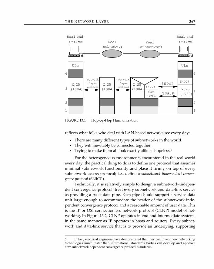
reflects what folks who deal with LAN-based networks see every day:
• There are many different types of subnetworks in the world.• They will inevitably be connected together.• Trying to make them all look exactly alike is hopeless.6
For the heterogeneous environments encountered in the real worldevery day, the practical thing to do is to define one protocol that assumesminimal subnetwork functionality and place it firmly on top of everysubnetwork access protocol; i.e., define a subnetwork independent conver-gence protocol (SNICP).
Technically, it is relatively simple to design a subnetwork-indepen-dent convergence protocol: treat every subnetwork and data-link serviceas providing a basic data pipe. Each pipe should support a service dataunit large enough to accommodate the header of the subnetwork-inde-pendent convergence protocol and a reasonable amount of user data. Thisis the IP or OSI connectionless network protocol (CLNP) model of net-working. In Figure 13.2, CLNP operates in end and intermediate systemsin the same manner as IP operates in hosts and routers. Every subnet-work and data-link service that is to provide an underlying, supporting
T H E N E T W O R K L A Y E R 367
FIGURE 13.1 Hop-by-Hop Harmonization
Realsubnetwor
4
3
2
1
ULs
4
3
2
1
SNDCP
Real endsystem
Real endsystem
ULs
Realsubnetwork
Network
layer
protocol
SNAcP
X.25(1984)
SNDCF
SNDCFX.25(1984)
X.25
(1980)
Network
layer
protocolX.25(1984) X.25
(1980)
6. In fact, electrical engineers have demonstrated that they can invent new networkingtechnologies much faster than international standards bodies can develop and approvenew subnetwork dependent convergence protocol standards.
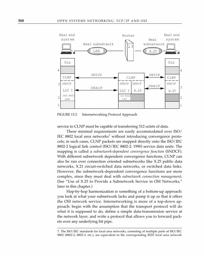
service to CLNP must be capable of transferring 512 octets of data. These minimal requirements are easily accommodated over ISO/
IEC 8802 local area networks7 without introducing convergence proto-cols; in such cases, CLNP packets are mapped directly onto the ISO/IEC8802-2 logical link control (ISO/IEC 8802-2: 1990) service data units. Themapping is called a subnetwork-dependent convergence function (SNDCF).With different subnetwork dependent convergence functions, CLNP canalso be run over connection oriented subnetworks like X.25 public datanetworks, X.21 circuit-switched data networks, or switched data links.However, the subnetwork-dependent convergence functions are morecomplex, since they must deal with subnetwork connection management.(See “Use of X.25 to Provide a Subnetwork Service in OSI Networks,”later in this chapter.)
Hop-by-hop harmonization is something of a bottom-up approach:you look at what your subnetwork lacks and pump it up so that it offersthe OSI network service. Internetworking is more of a top-down ap-proach: begin with the assumption that the transport protocol will dowhat it is supposed to do, define a simple data-transmission service atthe network layer, and write a protocol that allows you to forward pack-ets over any underlying bit pipe.
O P E N S Y S T E M S N E T W O R K I N G : T C P / I P A N D O S I368
FIGURE 13.2 Internetworking Protocol Approach
Real subnetwork
4
3
2
1
ULs
4
3
2
1
SNACP
X.25
Real endsystem
Real endsystem
ULs
Realsubnetwork
SNICP
SNAcP
LAN X.25
SNICP
LLC 1
CLNPCLNP CLNP
SNDCF
X.25
SNDCF SNDCF
Router
ISO 8802
LANISO 8802LAN
LLC 1
SNDCF
7. The ISO/IEC standards for local area networks, consisting of multiple parts of ISO/IEC8802 (8802-2, 8802-3, etc.), are equivalent to the corresponding IEEE local area network
Although the use of CLNP to provide a uniform connectionlessnetwork service over any combination of underlying “sub”net-
works seems natural to anyone familiar with the internetworking architecturethat underlies the TCP/IP Internet (and many vendor-proprietary networks), itwas politically naive to propose it as an alternative to hop-by-hop harmonizationin the early years of OSI development. Why? The answer may be found in thephrase “placing it firmly and uniformly on top of every subnetwork access pro-tocol,” which suggests that those subnetwork access protocols—the pride andjoy, not to mention the economic staples, of many large public network serviceproviders—are somehow deficient, not up to the demands of providing the OSInetwork service. To recognize themselves as providers only of edge-to-edge ser-vice (from subnetwork entry-point to subnetwork exit point) rather than end-to-end service (from end user to end user), the public networks would have had toabandon their claims of networking omnipresence and omniscience. Naturally,they were initially unwilling to do this. With hindsight, however, it can be seenthat their reluctance to recognize the importance of internetworking delayed thecompletion of work on the OSI network layer for at least five years and is one ofthe reasons why OSI networking today is more of a “missed opportunity” than areality.
As if to prove that history repeats itself even in fields with the compara-tively brief history of networking, the basic mistake of many X.25 proponents ofthe late 1970s—believing that a single network technology could be extrapolatedinto a monolithic global data network—is being replayed in the 1990s by someextremist proponents of asynchronous transfer mode (ATM), who argue that“internetworking” is obsolete, because they can build a worldwide ATM-every-where wide area network that will “seamlessly” interconnect ATM local areanetworks, and there won’t be any need to have Ethernets, token rings, fiber-dis-tributed data interfaces, or any other “old” network technology. And nothingbetter will ever be invented. Ever. Really.
Before we close the subject of OSI network layer architecture, it will beuseful to examine the issues that can be debated when political hats areremoved and the technical pros and cons of connection-oriented net-works and datagram networks are examined.
Network connections generally have the following characteristics:
• Once a network connection is established, all data packets travelalong the same path. Network connections thus offer low routing
✧AHA✧
T H E N E T W O R K L A Y E R 369
Connections orConnectionless?
standards, consisting of multiple parts of IEEE 802 (802.2, 802.3, etc.).
overhead, but they are not resilient; if one link in the path breaks,the connection is broken.
• Network connections provide fixed paths with guaranteed qualityof service characteristics (bandwidth, delay, residual error rate);during connection establishment, resources are reserved at each“hop” to minimize quality of service variability. Although this isgood for the established network connections, the reserved re-sources cannot be used by or for other network connections whilean established network connection is idle.
• Network connection state must be maintained at every intermediate“hop.”
• Network connection-establishment overhead is unacceptable forbursty data. Some applications require very high bandwidth for avery brief spurt or “burst.” For example, if a user of a distributedfile service attempts to retrieve a file from a remote server across alocal area network, that user wants the read completed as quicklyas if the file were stored locally (see Sandberg, 1988). The networkservice must exhibit both high throughput and low latency.Network connection establishment is more time-consuming thansending a datagram and in these circumstances is ill-advised; con-sider how difficult it might be for a file server to reserve a virtualcircuit having the bandwidth necessary to read a 4-megabyte file insome measure of milliseconds and do so for many clients.
Connectionless data transfer has its own set of strengths and weak-nesses:
• Datagrams are a best-effort delivery; reliability mechanisms, if re-quired, must be provided at the transport layer.
• State machine handling of datagrams at intermediate hops is greatlysimplified when compared to network connections.
• Since each packet is routed independently, routing overhead isimposed at each hop. In most routing systems, however, routing isadaptive in the face of failures.
• Resources are used as needed (no resource reservation per networkconnection); however, to minimize quality of service variability,multilevel congestion-management mechanisms and possibly typeof service routing may be required.
• There is no connection setup. Resources are allocated as needed or“on demand.” Connectionless data transfer is better suited for sup-porting bursty data applications.
A colleague (Winston Edmond, who works with one of the authors
O P E N S Y S T E M S N E T W O R K I N G : T C P / I P A N D O S I370
at Bolt Beranek and Newman) has suggested a useful thumbnail descrip-tion of the difference between datagrams and connections:
• Datagrams: The hosts don’t tell the network anything about the traf-fic they are about to send. In this case, the best the network can dois to monitor the dynamic behavior of the hosts and hope that pasthistory is a guide to future behavior (and that the network designerhas provisioned the network so as to accommodate most, if not all,such behavior).
• Connections: The hosts tell the network what they want to do andask for guarantees (bandwidth, maximum delay, maximum errorrate, etc.). In this case, there is an actual setup phase during whichthe required resources are allocated (if possible; explicit connectionsetup also provides the network with the opportunity to refuse ser-vice entirely in situations in which it cannot provide the requestedguarantees), and the success or failure of the setup is reported tothe hosts before actual data exchange begins.
(Edmond goes on to compare these two types of network servicewith a hybrid called “flows,” in which the hosts tell the network whatthey are about to do but don’t ask for any guarantees—thereby enablingthe network to improve somewhat its otherwise poorly informed antici-pation of their future behavior without forcing it to preallocate its re-sources in order to be sure of meeting static per-connection performancecriteria. See Partridge [1992] for a discussion of “flows.”)
There are more pros and cons for both types of service, to be sure.Some of these are bit niggling (e.g., datagrams require more “headerstuff” than network connections once the connection is established) andsome religious (but we’ve always offered connections!). Although notexhaustive, these lists provide readers with enough insight to appear tobe “in the know” the next time the issue of “connections or datagrams”comes up during polite dinner conversation.
The “Connections versus Connectionless” standoff is oftencited as the ultimate tragi-comedy in OSI. But although the
OSI environment is certainly partitioned into connection-oriented and connec-tionless worlds at the network layer, and different transport protocols are usedover both types of network service, there remains hope for reunification. Severalalternatives exist:
• Build network relays. These are truly awful beasts. They constrain topolo-gies, and are difficult to build. And they most often rely on the operation
✧AHA✧
T H E N E T W O R K L A Y E R 371
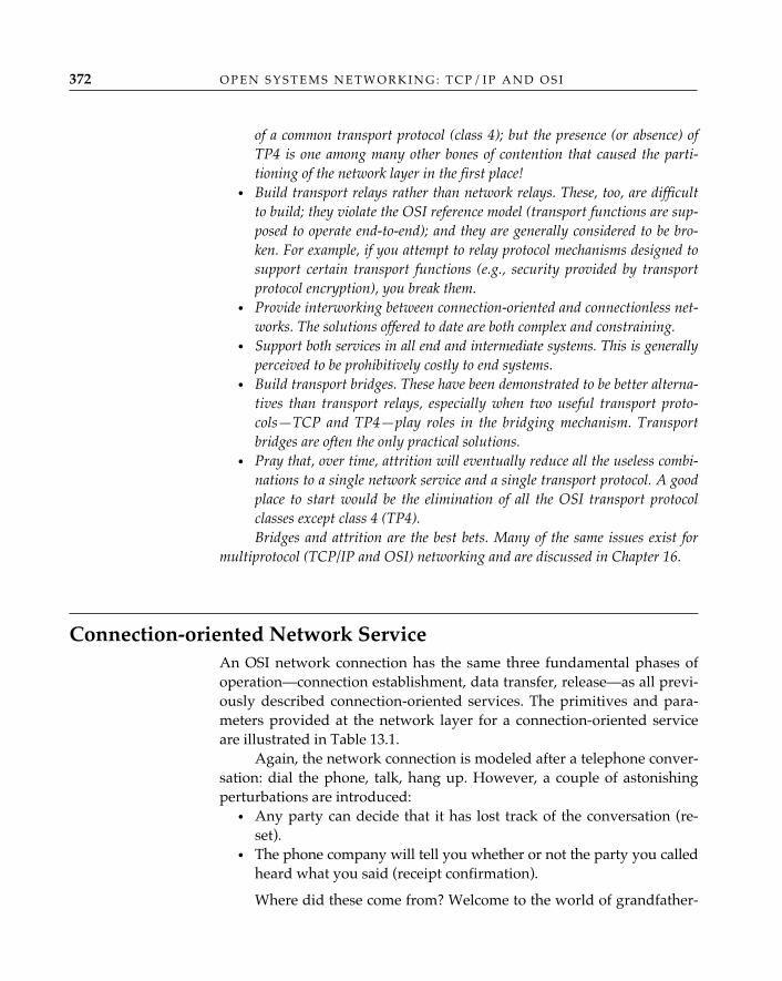
of a common transport protocol (class 4); but the presence (or absence) ofTP4 is one among many other bones of contention that caused the parti-tioning of the network layer in the first place!
• Build transport relays rather than network relays. These, too, are difficultto build; they violate the OSI reference model (transport functions are sup-posed to operate end-to-end); and they are generally considered to be bro-ken. For example, if you attempt to relay protocol mechanisms designed tosupport certain transport functions (e.g., security provided by transportprotocol encryption), you break them.
• Provide interworking between connection-oriented and connectionless net-works. The solutions offered to date are both complex and constraining.
• Support both services in all end and intermediate systems. This is generallyperceived to be prohibitively costly to end systems.
• Build transport bridges. These have been demonstrated to be better alterna-tives than transport relays, especially when two useful transport proto-cols—TCP and TP4—play roles in the bridging mechanism. Transportbridges are often the only practical solutions.
• Pray that, over time, attrition will eventually reduce all the useless combi-nations to a single network service and a single transport protocol. A goodplace to start would be the elimination of all the OSI transport protocolclasses except class 4 (TP4).Bridges and attrition are the best bets. Many of the same issues exist for
multiprotocol (TCP/IP and OSI) networking and are discussed in Chapter 16.
Connection-oriented Network ServiceAn OSI network connection has the same three fundamental phases ofoperation—connection establishment, data transfer, release—as all previ-ously described connection-oriented services. The primitives and para-meters provided at the network layer for a connection-oriented serviceare illustrated in Table 13.1.
Again, the network connection is modeled after a telephone conver-sation: dial the phone, talk, hang up. However, a couple of astonishingperturbations are introduced:
• Any party can decide that it has lost track of the conversation (re-set).
• The phone company will tell you whether or not the party you calledheard what you said (receipt confirmation).
Where did these come from? Welcome to the world of grandfather-
O P E N S Y S T E M S N E T W O R K I N G : T C P / I P A N D O S I372
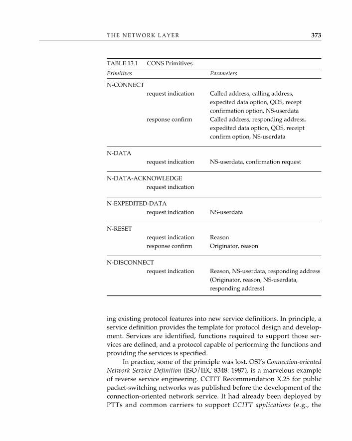
ing existing protocol features into new service definitions. In principle, aservice definition provides the template for protocol design and develop-ment. Services are identified, functions required to support those ser-vices are defined, and a protocol capable of performing the functions andproviding the services is specified.
In practice, some of the principle was lost. OSI’s Connection-orientedNetwork Service Definition (ISO/IEC 8348: 1987), is a marvelous exampleof reverse service engineering. CCITT Recommendation X.25 for publicpacket-switching networks was published before the development of theconnection-oriented network service. It had already been deployed byPTTs and common carriers to support CCITT applications (e.g., the
T H E N E T W O R K L A Y E R 373
TABLE 13.1 CONS Primitives
Primitives Parameters
N-CONNECTrequest indication Called address, calling address,
expecited data option, QOS, receptconfirmation option, NS-userdata
response confirm Called address, responding address,expedited data option, QOS, receiptconfirm option, NS-userdata
N-DATArequest indication NS-userdata, confirmation request
N-DATA-ACKNOWLEDGErequest indication
N-EXPEDITED-DATArequest indication NS-userdata
N-RESETrequest indication Reasonresponse confirm Originator, reason
N-DISCONNECTrequest indication Reason, NS-userdata, responding address
(Originator, reason, NS-userdata,responding address)
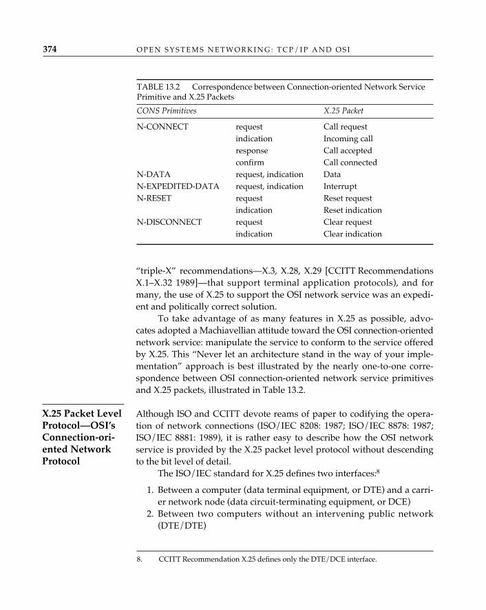
“triple-X” recommendations—X.3, X.28, X.29 [CCITT RecommendationsX.1–X.32 1989]—that support terminal application protocols), and formany, the use of X.25 to support the OSI network service was an expedi-ent and politically correct solution.
To take advantage of as many features in X.25 as possible, advo-cates adopted a Machiavellian attitude toward the OSI connection-orientednetwork service: manipulate the service to conform to the service offeredby X.25. This “Never let an architecture stand in the way of your imple-mentation” approach is best illustrated by the nearly one-to-one corre-spondence between OSI connection-oriented network service primitivesand X.25 packets, illustrated in Table 13.2.
Although ISO and CCITT devote reams of paper to codifying the opera-tion of network connections (ISO/IEC 8208: 1987; ISO/IEC 8878: 1987;ISO/IEC 8881: 1989), it is rather easy to describe how the OSI networkservice is provided by the X.25 packet level protocol without descendingto the bit level of detail.
The ISO/IEC standard for X.25 defines two interfaces:8
1. Between a computer (data terminal equipment, or DTE) and a carri-er network node (data circuit-terminating equipment, or DCE)
2. Between two computers without an intervening public network(DTE/DTE)
O P E N S Y S T E M S N E T W O R K I N G : T C P / I P A N D O S I374
X.25 Packet LevelProtocol—OSI’sConnection-ori-ented NetworkProtocol
TABLE 13.2 Correspondence between Connection-oriented Network ServicePrimitive and X.25 Packets
CONS Primitives X.25 Packet
N-CONNECT request Call requestindication Incoming callresponse Call acceptedconfirm Call connected
N-DATA request, indication DataN-EXPEDITED-DATA request, indication InterruptN-RESET request Reset request
indication Reset indicationN-DISCONNECT request Clear request
indication Clear indication
8. CCITT Recommendation X.25 defines only the DTE/DCE interface.
TheDTE/DCEphysical interface can be leased or switched. The DTE/DTE physical interface can be a leased line, a switched circuit, or a local areanetwork (ISO/IEC 8881: 1989). Both virtual-circuit and permanent virtual-circuit modes of operation are accommodated. In the virtual-circuit modeof operation, a connection must be set up, used, and disconnected. With apermanent virtual-circuit arrangement, a subscriber has facilities andresources permanently assigned between two DTEs by a carrier (the callis “always there”). These alternatives are illusrated in Figure 13.3.
Figure 13.4 illustrates (in the abstract) the three phases of a networkconnection established across a switched (VC mode of operation) X.25circuit.9 An N-CONNECT.request primitive causes DTE A to issue anX.25 call request packet. The DCE receives this request, and the networkconstructs a path between DTE A and DTE B, allocating and reservingresources of packet switches that comprise the path along the way. The
T H E N E T W O R K L A Y E R 375
FIGURE 13.3 X.25 Interfaces
DTEA
DTEB
DCE DCE
Virtual circuit (VC)
or permanent
virtual circuit (PVC
DTEA
DTEB
(e.g., a PDN)
Leased line, dial-up, LAN
X.25PLP
X.25PLP
X.25PLP
X.25PLP
9. The procedures for operating the X.25 packet-level protocol between DTEs withoutan intervening public network are virtually identical. This description covers only thoseaspects of X.25 VC operation relevant to the packet level of operation. At the data-linklevel, both leased-line and circuit-switched access to a DCE are provided by many carriernetworks. CCITT Recommendation X.32 describes additional packet-level considerations(e.g., user identification) typically required for switched access to a public network.
terminus DCE issues an incoming call packet to DTE B, which causes anN-CONNECT.indication. DTE B issues a call-accepted packet, and DTE Aeventually receives a call-connected packet from the DCE. All X.25 datapackets exchanged during this virtual call are forwarded along the pathcreated by the DCEs during network connection establishment. When thenetwork service user at DTE A elects to close the network connection, itissues an N-DISCONNECT.request, causing DTE A to issue a clear requestpacket. This is processed by the DCE and results in the generation of aclear indication packet to DTE B. DTE B acknowledges receipt of the clearindication by returning a clear confirmation packet. This packet eventuallymakes its way back to DTE A, causing the generation of an N-DISCON-NECT.confirmation. Network connection disconnection is described inISO/IEC 8348 as “unconditional and possibly destructive” (honest, this iswhat it says, you can look it up).
During the data phase, the X.25 packet level protocol providessequence control, flow control, expedited data (using the interrupt facilityand packets), and error notification. Reset, carefully distinguished as afeature rather than an error notification, offers a means by which a net-work connection ”can be returned to a defined state and the activities oftwo network service users synchronized.”10 Reset can be network serviceprovider– or network service user–initiated. Negotiation and use of theD-bit facility enables the receipt confirmation function of the OSI networkservice. Receipt confirmation allows a network service user to requestend-to-end acknowledgment of the delivery of data it is transmitting. Inits implementation, receipt confirmation signals to the network serviceuser that the X.25 data packets transmitted have been acknowledged.Although this is a clear violation of the OSI reference model (the internalmachinations of an [N]-layer protocol should be hidden from an [N]-ser-vice user), the facility was “grandfathered” into the OSI connection-ori-ented network service over the protests of purists, largely because it wasa tariffed facility.
When a connectionless network service is provided to communicatingtransport entities in OSI, the X.25 packet-level protocol plays the role of a
O P E N S Y S T E M S N E T W O R K I N G : T C P / I P A N D O S I376
Use of X.25 toProvide a Subnet-work Service inOSI Networks
10. ISO/IEC 8348 does not provide a definition of “defined state,” nor does it describewhat activities the network service users “synchronize.” From personal experience, we maysay that defined state is “Some of your data are lost; I hope someone was keeping track . . .”The synchronization activities are transport protocol–dependent; for example, upon receiptof a reset indication, transport classes 0 and 2 give up and disconnect (big help . . .), butclasses 1 and 3 initiate resynchronization procedures (see Chapter 12). TP4 is completelyresilient to reset indication, treating it like any other error . . . er, feature.
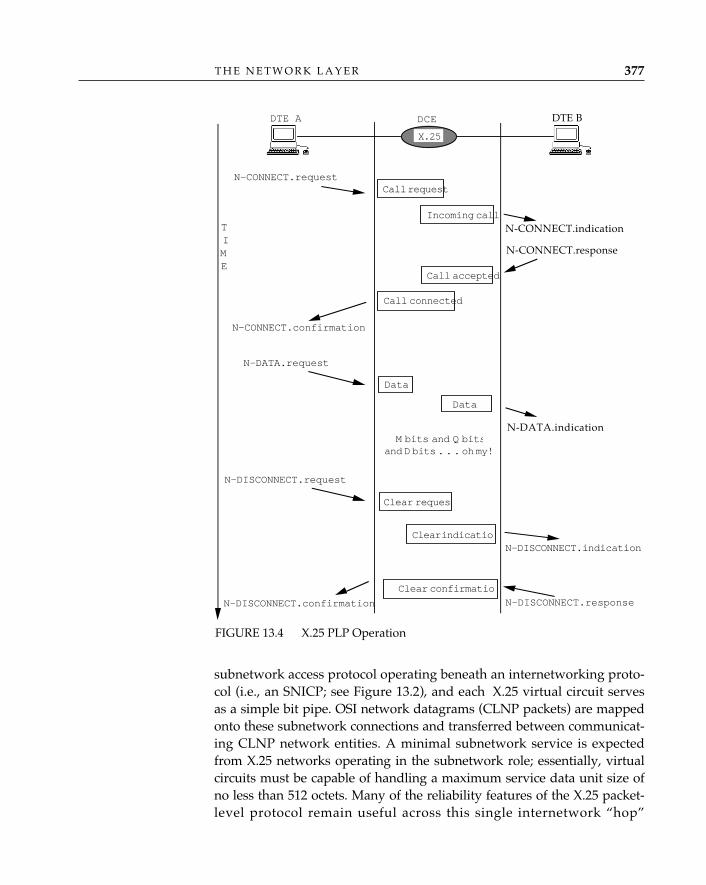
subnetwork access protocol operating beneath an internetworking proto-col (i.e., an SNICP; see Figure 13.2), and each X.25 virtual circuit servesas a simple bit pipe. OSI network datagrams (CLNP packets) are mappedonto these subnetwork connections and transferred between communicat-ing CLNP network entities. A minimal subnetwork service is expectedfrom X.25 networks operating in the subnetwork role; essentially, virtualcircuits must be capable of handling a maximum service data unit size ofno less than 512 octets. Many of the reliability features of the X.25 packet-level protocol remain useful across this single internetwork “hop”
T H E N E T W O R K L A Y E R 377
N-CONNECT.response
N-CONNECT.indication
DTE B
N-DATA.indication
Call request
Incoming call
DTE A DCE
N-CONNECT.request
Call accepted
Call connected
N-CONNECT.confirmation
X.25
Data
N-DATA.request
M bits and Q bitsand D bits . . . oh my!
Data
Clear request
Clear indicationN-DISCONNECT.indication
N-DISCONNECT.request
N-DISCONNECT.responseN-DISCONNECT.confirmation
Clear confirmation
TIME
FIGURE 13.4 X.25 PLP Operation
(although the authors know of no implementations that make use ofreceipt confirmation when X.25 plays this role), but unnecessary. WhenX.25 virtual circuits are used to provide a subnetwork service to CLNP,subnetwork-dependent convergence functions specific to X.25 are used toset up, transfer data over, and tear down “subnetwork connections”between communicating CLNP network entities. The subnetwork connec-tion-management functions for X.25 are described in ISO/IEC 8473 (thestandard for CLNP), and the description is generic enough to apply to afamily of switched, connection-oriented network services, including pack-et-mode Integrated Services Digital Networks (ISDN), Frame Relay, andnew “cell-relay” services (see Chapter 15).
Subnetwork connection management begins as a relatively simpleprocess. To send a CNLP packet across an X.25 public data network, forexample, an X.25 virtual circuit must be established. If the CNLP packetis the first to be sent to a particular destination reachable via the X.25public data network, the X.25 call-setup procedures must be initiated(connection establishment) and a virtual circuit must be established.Subsequent CLNP packets can be sent over the same virtual circuit.11 Theprocess is relatively simple if there is no cause to tear down the X.25 vir-tual circuit; if, however, there is a cost associated with X.25 call duration(for example, one is charged for how long one remains on a telephoneregardless of whether one talks constantly or not), it may be more eco-nomical to tear down the virtual circuit when there are no longer anydata to send (trading the cost of call duration for the cost of call setup thenext time a packet must be sent to that destination). Determining when totear down the X.25 virtual circuit is tricky; like telephones, the virtual cir-cuit is full-duplex, and one party may think the conversation has endedwhile the party at the other end still has something to say. Timers are rec-ommended to impose a maximum idle time on a virtual circuit; i.e., theexpiration of a timer indicates that neither party has said anything for awhile, so it’s presumably safe to clear the virtual circuit. But timers alonedo not entirely solve the problem of synchronization, which may requireadditional protocol interaction on behalf of the parties sharing the virtualcircuit (i.e., one computer would ask permission to tear down the call,and would only do so if granted by its peer).
In the Internet architecture, X.25 is not considered to be a protocol of the
O P E N S Y S T E M S N E T W O R K I N G : T C P / I P A N D O S I378
11. Can be, but need not be; the standards permit considerable flexibility in the way inwhich virtual circuits are managed, so as to accommodate the wide variety of tariffs thatgovern the use of public networks.
TCP/IP Use ofX.25
network layer. X.25 is one of many network interfaces on top of which IPis run. Both DTE/DTE and DTE/DCE modes of operation are supported(Defense Communications Agency 1983; RFC 877). A more recentInternet RFC describes multiprotocol interconnection over X.25 andISDN in the packet mode (RFC 1356). It doesn’t change X.25’s role inTCP/IP; rather, it corrects some of the errors and ambiguities in the RFC877 text and aligns it with ISO and CCITT standards that have been writ-ten since RFC 877 was published. One important change to the IP encap-sulation is that RFC 1356 recommends an increase in the allowed IP data-gram maximum transmission unit from 576 to 1,600 octets, to facilitatelocal area network interconnection.
Connectionless Network ServiceBoth OSI and TCP/IP support a connectionless network service: OSI asan alternative to network connections and TCP/IP as the only game intown (TCP/IP networking can use connections to transfer IP datagrams,but IP offers only a connectionless service to its users). The OSI stan-dards attach great importance to the way in which transport connectionsare bound to network connections when the OSI connection-orientednetwork service is used, because in OSI, the connection-oriented networkservice represents, in fact, an attempt to perform some of the functions ofthe transport layer in the network layer. When the connectionless net-work service of OSI or TCP/IP is used, the coupling of connections is notan issue, and neither service attempts to pass any of the connection-ori-ented features that may be present in underlying subnetworks throughto the transport layer.
OSI’s connectionless network service (CLNS) (ISO/IEC 8348: 1993)is a best-effort-delivery service. Like a letter one submits to the postal ser-vice, each network service data unit submitted to the OSI connectionlessnetwork service contains all the addressing and service quality informa-tion necessary to forward the packet from its source to its destination,over potentially many intermediate “hops” along the way (see Figure 13.5).
The details of the OSI connectionless network service can be found inISO/IEC 8348. A “datagram” primitive (N-UNITDATA) is used todescribe the process of submitting user data to and receiving user datafrom the connectionless network service provider (see Table 13.3). Theservice definition is quite simple; after all, how much can one say about adatagram?
T H E N E T W O R K L A Y E R 379
Datagram Servicein OSI
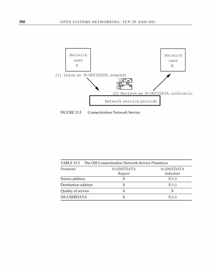
O P E N S Y S T E M S N E T W O R K I N G : T C P / I P A N D O S I380
FIGURE 13.5 Connectionless Network Service
Network service provide
(1) Issue an N-UNITDATA.request
NetworkuserA
NetworkuserB
(2) Recieve an N-UNITDATA.indication
TABLE 13.3 The OSI Connectionless Network Service Primitives
Parameter N-UNITDATA N-UNITDATARequest Indication
Source address X X (=)
Destination address X X (=)
Quality of service X X
NS-USERDATA X X (=)
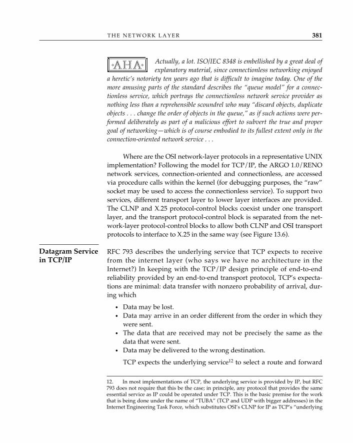
Actually, a lot. ISO/IEC 8348 is embellished by a great deal ofexplanatory material, since connectionless networking enjoyed
a heretic’s notoriety ten years ago that is difficult to imagine today. One of themore amusing parts of the standard describes the “queue model” for a connec-tionless service, which portrays the connectionless network service provider asnothing less than a reprehensible scoundrel who may “discard objects, duplicateobjects . . . change the order of objects in the queue,” as if such actions were per-formed deliberately as part of a malicious effort to subvert the true and propergoal of networking—which is of course embodied to its fullest extent only in theconnection-oriented network service . . .
Where are the OSI network-layer protocols in a representative UNIXimplementation? Following the model for TCP/IP, the ARGO 1.0/RENOnetwork services, connection-oriented and connectionless, are accessedvia procedure calls within the kernel (for debugging purposes, the “raw”socket may be used to access the connectionless service). To support twoservices, different transport layer to lower layer interfaces are provided.The CLNP and X.25 protocol-control blocks coexist under one transportlayer, and the transport protocol-control block is separated from the net-work-layer protocol-control blocks to allow both CLNP and OSI transportprotocols to interface to X.25 in the same way (see Figure 13.6).
RFC 793 describes the underlying service that TCP expects to receivefrom the internet layer (who says we have no architecture in theInternet?) In keeping with the TCP/IP design principle of end-to-endreliability provided by an end-to-end transport protocol, TCP’s expecta-tions are minimal: data transfer with nonzero probability of arrival, dur-ing which
• Data may be lost.• Data may arrive in an order different from the order in which they
were sent.• The data that are received may not be precisely the same as the
data that were sent.• Data may be delivered to the wrong destination.
TCP expects the underlying service12 to select a route and forward
✧AHA✧
T H E N E T W O R K L A Y E R 381
Datagram Servicein TCP/IP
12. In most implementations of TCP, the underlying service is provided by IP, but RFC793 does not require that this be the case; in principle, any protocol that provides the sameessential service as IP could be operated under TCP. This is the basic premise for the workthat is being done under the name of “TUBA” (TCP and UDP with bigger addresses) in theInternet Engineering Task Force, which substitutes OSI’s CLNP for IP as TCP’s “underlying
a packet based on the globally unique address it provides. The underly-ing service must also be capable of transferring maximum TCP segmentsize of at least 536 octets (see RFC 879).
RFC 793 also formally describes the send and receive operations.For send (NET_SEND), TCP submits the following parameters to theunderlying service:
• Source and destination addresses• Protocol identifier (identifying the service user as TCP)• Type-of-service indicators—precedence, reliability, delay, through-
put• A “don’t fragment” indicator• A recommended “time to live” value• The length of the data being sent, in octets• A data identifier that distinguishes this unit of data from others
sent by the same upper-layer protocol (TCP user)• Options—a selection from the menu of options offered by IP or an
equivalent underlying service• Data
O P E N S Y S T E M S N E T W O R K I N G : T C P / I P A N D O S I382
service” but keeps all the other TCP/IP protocols. A description of TUBA may be found inRFC 1347 and in Ford (1993), which is part of a special issue of IEEE Network magazinedevoted to protocols that are proposed as successors to IP in the Internet.
OSIupperlayers
TCPapplications
UNIX user space
Sockets
OSItransportprotocols
TCPandIP Kernel
Networkinterfaces
CLNPX.25
SNDC F
X.25 driver
Figure 13.6 OSI Network Layer in a Representative UNIX Implementation
For a receive operation (NET_DELIVER), TCP receives the follow-ing parameters from the underlying service:
• Source and destination addresses• Protocol identifier• Type-of-service indicators—precedence, reliability, delay, through-
put• The length of the data received in octets• Options selected by the sender• Data
In a TCP/IP implementation, only one transport–to–lower-layerinterface is required (see Figure 13.6).
Internetworking ProtocolsOSI’s CLNP (ISO/IEC 8473: 1993) is functionally identical to the Inter-net’s IP (RFC 791), so the two internetworking protocols—subnetwork-independent convergence protocols in Internal Organization of the NetworkLayer jargon—can be discussed in parallel. Both CLNP and IP are best-effort-delivery network protocols. Bit niggling aside, they are virtuallyidentical. The major difference between the two is that CLNP accommo-dates variable-length addresses, whereas IP supports fixed, 32-bitaddresses. Table 13.4 compares the functions of CLNP to those of IP.Figures 13.7 and 13.8 illustrate the header formats of CLNP and IP,respectively.
The functions performed by the two protocols are also closely relat-ed as indicated in the following subsection (see also Postel, Sunshine,and Cohen [1981] and Piscitello and Chapin [1984]).
Header Composition Function—This function13 interprets the Ns-UNIT-DATA.request parameters and constructs the corresponding CLNP dataunit. In IP, this amounts to IP’s processing the upper-layer protocol’ssend (NET-SEND) parameters and constructing the corresponding data-gram.
Header Decomposition Function—This function interprets the header
T H E N E T W O R K L A Y E R 383
13. CLNP has a silly protocol function called “header format analysis,” which amounts toexamining the first octet of the protocol (the network-layer protocol identifier, or NLPID) todetermine whether CLNP or the brain-damaged “inactive network layer protocol” is present.The inactive network layer protocol is an abomination; a single octet of 0 may be encoded inthe NLPID field to denote “There’s no network layer protocol present.”
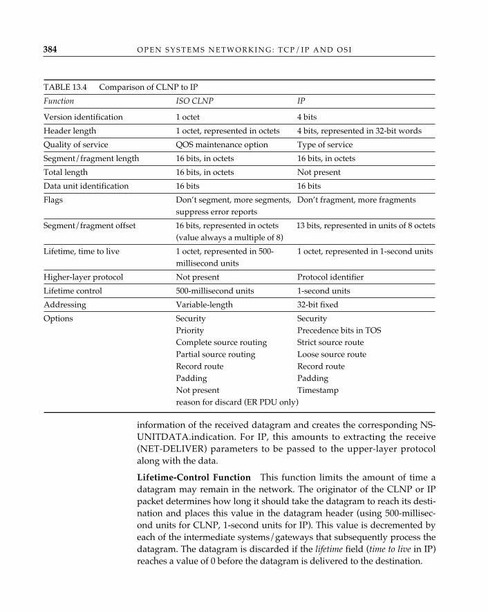
information of the received datagram and creates the corresponding NS-UNITDATA.indication. For IP, this amounts to extracting the receive(NET-DELIVER) parameters to be passed to the upper-layer protocolalong with the data.
Lifetime-Control Function—This function limits the amount of time adatagram may remain in the network. The originator of the CLNP or IPpacket determines how long it should take the datagram to reach its desti-nation and places this value in the datagram header (using 500-millisec-ond units for CLNP, 1-second units for IP). This value is decremented byeach of the intermediate systems/gateways that subsequently process thedatagram. The datagram is discarded if the lifetime field (time to live in IP)reaches a value of 0 before the datagram is delivered to the destination.
O P E N S Y S T E M S N E T W O R K I N G : T C P / I P A N D O S I384
TABLE 13.4 Comparison of CLNP to IP
Function ISO CLNP IP
Version identification 1 octet 4 bits
Header length 1 octet, represented in octets 4 bits, represented in 32-bit words
Quality of service QOS maintenance option Type of service
Segment/fragment length 16 bits, in octets 16 bits, in octets
Total length 16 bits, in octets Not present
Data unit identification 16 bits 16 bits
Flags Don’t segment, more segments, Don’t fragment, more fragmentssuppress error reports
Segment/fragment offset 16 bits, represented in octets 13 bits, represented in units of 8 octets(value always a multiple of 8)
Lifetime, time to live 1 octet, represented in 500- 1 octet, represented in 1-second unitsmillisecond units
Higher-layer protocol Not present Protocol identifier
Lifetime control 500-millisecond units 1-second units
Addressing Variable-length 32-bit fixed
Options Security SecurityPriority Precedence bits in TOSComplete source routing Strict source routePartial source routing Loose source routeRecord route Record routePadding PaddingNot present Timestampreason for discard (ER PDU only)
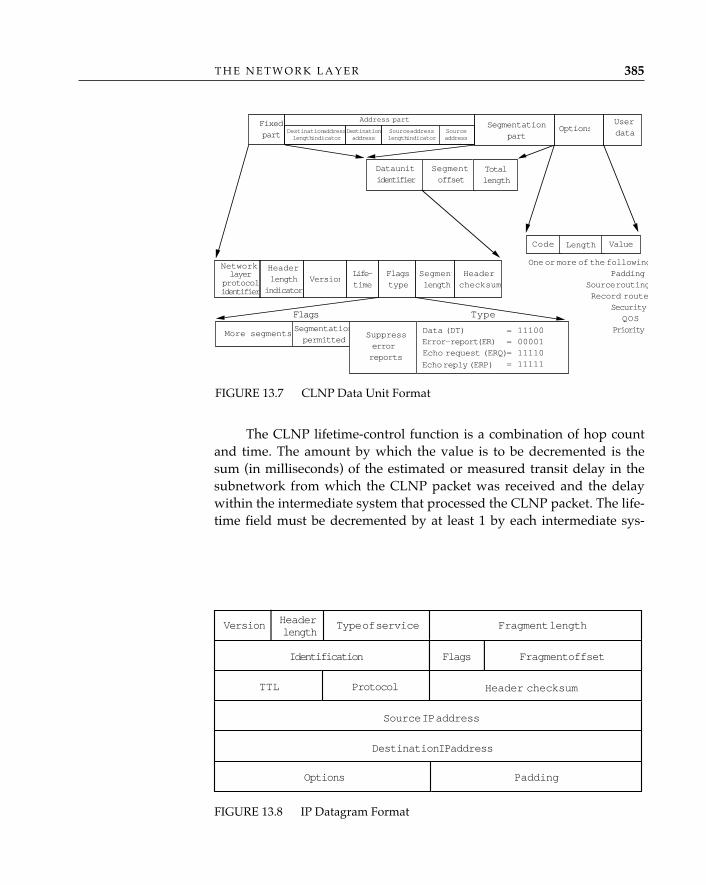
The CLNP lifetime-control function is a combination of hop countand time. The amount by which the value is to be decremented is thesum (in milliseconds) of the estimated or measured transit delay in thesubnetwork from which the CLNP packet was received and the delaywithin the intermediate system that processed the CLNP packet. The life-time field must be decremented by at least 1 by each intermediate sys-
T H E N E T W O R K L A Y E R 385
FIGURE 13.7 CLNP Data Unit Format
Headerchecksum
Userdata
Fixedpart
Options
NetworkSegmentlength
Data unitidentifier
Segmentoffset
Totallength
Segmentationpermitted
More segments
SA
Segmentationpart
Code Length Value
One or more of the followingPadding
Source routingRecord route
SecurityQOS
Priority
Source addresslength indicator
Sourceaddress
Destinationaddress
Destination addresslength indicator
Address part
Flagstype
Life-time
VersionHeaderlength
indicator
layerprotocolidentifier
Data (DT)Error-report (ER)Echo request (ERQ)
Echo reply (ERP)
= 11100= 00001= 11110= 11111
Flags Type
Suppresserrorreports
FIGURE 13.8 IP Datagram Format
Type of service Fragment length
Identification
Source IP address
Destination IP address
Options Padding
Version Headerlength
Flags Fragment offset
TTL Protocol Header checksum
tem.14 IP’s time to live (TTL) operates on a time basis; the upper-layerprotocol provides a maximum datagram lifetime in 1-second unitsamong the send parameters submitted to the datagram service.
Route PDU and Forward PDU Functions—The route PDU functiondetermines the network entity to which the datagram must be forwardedand the underlying service (i.e., the link) over which the datagram mustbe sent to reach this “next hop.” The forward PDU function submits thedatagram to the underlying service selected by the route PDU functionfor transmission to the next hop (it is here that subnetwork-dependentconvergence functions might be invoked—for example, to establish anX.25 virtual circuit to transmit the CLNP packet).
Header Error-Detection Function—This function protects intermediatesystems from undetected (bit) errors in the protocol-control informationof each datagram. An example of such an error is the misdelivery of adatagram as a result of the corruption of the destination address field. A16-bit arithmetic checksum based on Fletcher (1982) is employed in theCLNP; a similar mechanism protects the IP header from transmissionerrors.
The rules for processing the CLNP header checksum are as follows:
• Generate the checksum only once, when the initial packet is created.• Check it at each intermediate system, using a separate algorithm
from the one used for checksum generation.• Do not recompute the checksum, but adjust it (again, using a sepa-
rate algorithm) when modifying the header. (Fields of the CLNPheader may be modified by an intermediate system when it per-forms lifetime control and segmentation and when it performs cer-tain optional functions, such as recording of route or setting thecongestion-experienced bit in the QOS maintenance option.)
The rules for processing the IP header checksum are the same asthose for CLNP: generate the checksum when the IP segment is createdand check it at each router. In IP, the checksum is either adjusted withoutfull recomputation (as for CLNP) if only the time to live field in the head-er is changed, or completely recomputed if any other header fields arechanged.
Segmentation/Fragmentation Functions—The terms segmentation andfragmentation both refer to the process whereby an IP or a CLNP packet of
O P E N S Y S T E M S N E T W O R K I N G : T C P / I P A N D O S I386
14. Appendix B of ISO/IEC 8473 provides reasonable implementation guidelines for deter-mining datagram lifetime and reassembly lifetime control.
size N is broken up into smaller pieces if and when it becomes necessary totransmit the packet over a subnetwork for which the maximum packet sizeis less than N. The OSI standards prefer segmentation and the TCP/IP stan-dards fragmentation, but in most of what follows, the two terms (and othervariations of the roots segment and fragment) are used interchangeably.
Segmentation is the process of composing two or more new derivedCLNP packets—segments—from an initial CLNP packet.15 Segmen-tation can be performed only if the segmentation-permitted flag is set to1; otherwise, an intermediate system that receives a CLNP packet requir-ing segmentation must discard that packet.
CLNP segments are identified as being from the same initial packetwhen they have the same source and destination address pair and thesame data unit identifier. The value of the total length field in all segmentsof a given initial packet remains the same as the value originally speci-fied in the initial packet. This value may be used by a system to allocatebuffer space for the entire CLNP packet regardless of which segment(the first, any of the middle ones, or the last) is received first. The segmentoffset of each CLNP segment is set to the octet at which the segmentbegins with respect to the beginning of the initial packet (see Figure13.9). The more segments flag is set to 0 if the final octet of the initial pack-et is contained in this segment; otherwise, it is set to 1.
All header information from an initial CLNP packet except the val-ues of the segment length, segment offset, and checksum fields is copiedinto the header of all segments derived from that packet by fragmenta-tion. The value of the checksum field must be adjusted to reflect thechanges in the values of the segmentation part of the CLNP header, life-time field reductions, and changes to options (if any).
The IP fragmentation process is nearly identical to CLNP segmenta-tion. The protocol header of a fragment is copied or derived from theoriginal IP datagram, including its options. IP fragmentation can be per-formed only if the don’t fragment flag is set to may fragment (0); otherwise,a gateway that receives an IP datagram requiring fragmentation mustdiscard it. Fragments are identified as being from the same IP datagramwhen they have the same values for the following fields: datagram iden-
T H E N E T W O R K L A Y E R 387
15. The “initial” CLNP packet is the one constructed by the original sender of the packetin the source end system. When an incoming packet is broken up into segments for trans-mission over the “next-hop” subnetwork, each segment is transmitted as a CLNP packet,which becomes the “incoming” packet at the next-hop system on the path—where it mayhave to be fragmented again. An “initial” packet, therefore, really means either the initialpacket emitted by the source or any incoming packet (datagram or datagram segment) thatis “initial” with respect to the operation of CLNP in the system to which it is “incoming.”
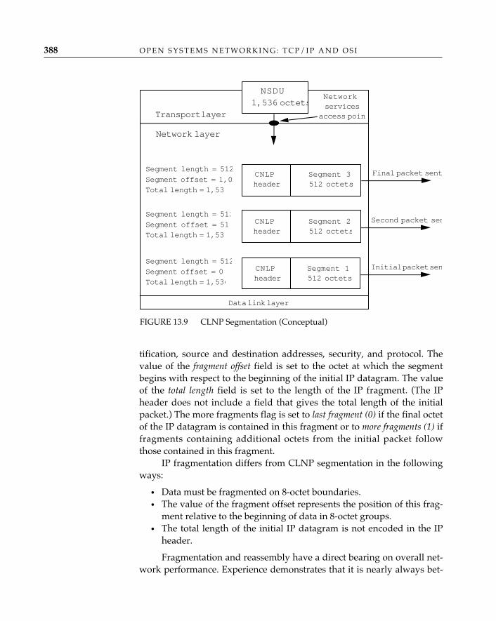
tification, source and destination addresses, security, and protocol. Thevalue of the fragment offset field is set to the octet at which the segmentbegins with respect to the beginning of the initial IP datagram. The valueof the total length field is set to the length of the IP fragment. (The IPheader does not include a field that gives the total length of the initialpacket.) The more fragments flag is set to last fragment (0) if the final octetof the IP datagram is contained in this fragment or to more fragments (1) iffragments containing additional octets from the initial packet followthose contained in this fragment.
IP fragmentation differs from CLNP segmentation in the followingways:
• Data must be fragmented on 8-octet boundaries.• The value of the fragment offset represents the position of this frag-
ment relative to the beginning of data in 8-octet groups.• The total length of the initial IP datagram is not encoded in the IP
header.
Fragmentation and reassembly have a direct bearing on overall net-work performance. Experience demonstrates that it is nearly always bet-
O P E N S Y S T E M S N E T W O R K I N G : T C P / I P A N D O S I388
CNLPheader
Segment 1512 octets
Segment length = 512
Segment offset = 0
Total length = 1,536
CNLPheader
Segment 2512 octets
Segment length = 512
Segment offset = 51
Total length = 1,53
CNLPheader
Segment 3512 octets
Segment length = 512
Segment offset = 1,02
Total length = 1,53
Transport layer
Network layer
NSDU1,536 octets
Final packet sent
Networkservices
access poin
Second packet sen
Initial packet sen
Data link layer
FIGURE 13.9 CLNP Segmentation (Conceptual)
ter for the source end system to compose and send one large datgramrather than lots of little “micrograms,” but a poorly implemented frag-mentation strategy can cause serious problems if that large initial packetmust later be fragmented to cross a subnetwork that cannot swallow itwhole (Kent and Mogul 1987). CLNP implementers can benefit by study-ing and extracting the directly relevant information recorded during thenearly 20 years of practical experience in implementing IP and observingits behavior. For example, Clark discusses IP datagram reassembly algo-rithms in RFC 815. Clark also provides a marvelous explanation of howtransport and internetwork protocols can be efficiently implemented inRFC 817. And the host and gateway requirements documents RFC 1122and RFC 1009 provide Internet guidelines for the implementation offragmentation and reassembly procedures.
Discard and Error-reporting Functions—As a last resort, both CLNPand IP discard datagrams when things go bad; e.g., when
• A protocol error is detected.• A checksum computation fails to yield the value indicated in the
checksum field of the datagram header.• Buffers are not available to store the datagram.• A datagram arrives that must be segmented (fragmented) before it
may be forwarded, but the flag settings don’t allow segmentation(fragmentation).
• Conditions for processing options cannot be satisfied.• The lifetime of a datagram expires. • The time allotted for reassembly of a datagram expires.
The “Internet Control Message Protocol” (ICMP; RFC 792) providesan elaborate mechanism for reporting errors in IP datagram processingat hosts and gateways.16 Equivalent functions are provided for CLNPusing a reason for discard option conveyed in the CLNP error report. ICMPmessages are encapsulated in IP datagrams and are distinguished fromother upper-layer protocols conveyed in IP datagrams by the value 1 inthe protocol (PROTO) field, whereas CLNP error reports are distin-guished from CLNP data packets by assigning a value of 1 to the typefield of the CLNP header.
ICMP messages and CLNP error reports are both datagrams, anddelivery of these messages is not guaranteed; generation of error-reportmessages, however, is mandatory in both protocols when certain errors
T H E N E T W O R K L A Y E R 389
16. Error reporting is not the only function of ICMP; see “TCP/IP and OSI ControlMessages” later in this chapter.
occur. The header of a discarded CLNP packet and as much of the dataas can be accommodated without segmentation is returned in the CLNPerror report. Similarly, every ICMP error message includes the IP headerand at least the first 8 data octets of the IP datagram that caused theerror. More than 8 octets may be sent, so long as the ICMP datagramlength remains less than or equal to 576 octets.
The errors reported by ICMP and CLNP are compared in Table13.5; for TCP/IP, however, it is always useful to refer to “Requirementsfor Internet Hosts—Communication Layers” (RFC 1122) for the precisecircumstances that precipitate the generation of an ICMP error message.
The process of generating error reports and ICMP messages is vir-tually the same. One never generates an error message about an erroroccurring during the processing of a CLNP error report or an ICMP mes-sage. ICMP messages are generated only when an error is detected in thefragment whose fragment offset is set to 0 (the first chunk of the data-gram); since no such restriction is explicitly stated in CLNP, one shouldconclude that it is appropriate to generate an error report PDU about anerror occurring in any segment of a CLNP data unit.
Options—Both CLNP and IP have lots of options. The sets of optionsdefined for the two protocols are virtually identical, but the processing isslightly different (as, of course, are the bits). Table 13.6 compares CLNPand IP options, and provides a brief explanation.
The composition of CLNP error reports is affected by the optionspresent in the discarded CLNP data packet; specifically, the CLNP errorreport must have the
• Same priority and QOS maintenance (if these options are support-ed).
• Same security. If this option is not supported, the CLNP errorreport should not be generated.
• Reversed complete source route. If this option is not supported, theCLNP error report should not be generated.
Padding, partial source routing and record route may be specifiedby the intermediate system generating the CLNP error report if theseoptions are supported.
ICMP and IP are completely independent protocols; however,which options from the discarded IP datagram are copied into the data-gram that conveys the ICMP error message datagrams remains an issuein the Internet Engineering Task Force. Currently, the IP datagram that isused to carry an ICMP message must set type of service to 0, and anyICMP message returned in response to a packet that contains an IP secu-
O P E N S Y S T E M S N E T W O R K I N G : T C P / I P A N D O S I390
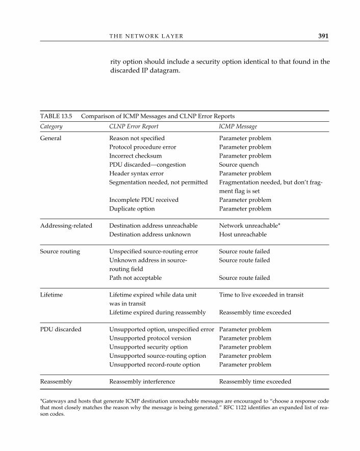
rity option should include a security option identical to that found in thediscarded IP datagram.
T H E N E T W O R K L A Y E R 391
TABLE 13.5 Comparison of ICMP Messages and CLNP Error Reports
Category CLNP Error Report ICMP Message
General Reason not specified Parameter problemProtocol procedure error Parameter problemIncorrect checksum Parameter problemPDU discarded—congestion Source quenchHeader syntax error Parameter problemSegmentation needed, not permitted Fragmentation needed, but don’t frag-
ment flag is setIncomplete PDU received Parameter problemDuplicate option Parameter problem
Addressing-related Destination address unreachable Network unreachable*Destination address unknown Host unreachable
Source routing Unspecified source-routing error Source route failedUnknown address in source- Source route failedrouting fieldPath not acceptable Source route failed
Lifetime Lifetime expired while data unit Time to live exceeded in transitwas in transitLifetime expired during reassembly Reassembly time exceeded
PDU discarded Unsupported option, unspecified error Parameter problemUnsupported protocol version Parameter problemUnsupported security option Parameter problemUnsupported source-routing option Parameter problemUnsupported record-route option Parameter problem
Reassembly Reassembly interference Reassembly time exceeded
*Gateways and hosts that generate ICMP destination unreachable messages are encouraged to “choose a response codethat most closely matches the reason why the message is being generated.” RFC 1122 identifies an expanded list of rea-son codes.
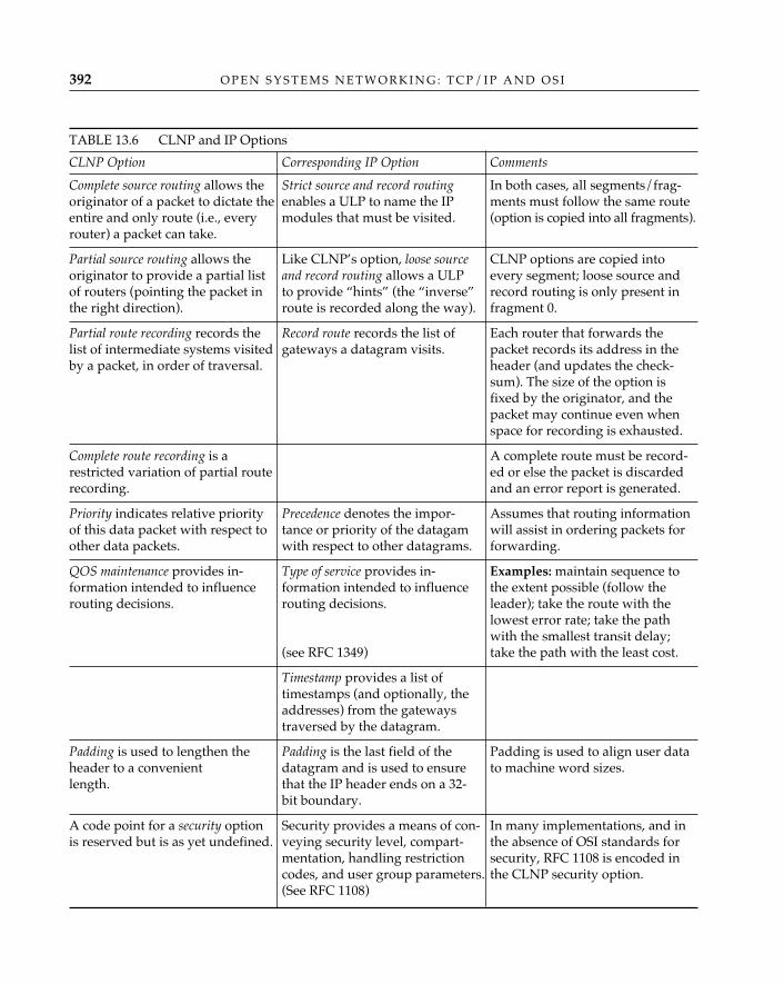
O P E N S Y S T E M S N E T W O R K I N G : T C P / I P A N D O S I392
TABLE 13.6 CLNP and IP Options
CLNP Option Corresponding IP Option Comments
Complete source routing allows the Strict source and record routing In both cases, all segments/frag-originator of a packet to dictate the enables a ULP to name the IP ments must follow the same route entire and only route (i.e., every modules that must be visited. (option is copied into all fragments).router) a packet can take.
Partial source routing allows the Like CLNP’s option, loose source CLNP options are copied intooriginator to provide a partial list and record routing allows a ULP every segment; loose source andof routers (pointing the packet in to provide “hints” (the “inverse” record routing is only present inthe right direction). route is recorded along the way). fragment 0.
Partial route recording records the Record route records the list of Each router that forwards the list of intermediate systems visited gateways a datagram visits. packet records its address in theby a packet, in order of traversal. header (and updates the check-
sum). The size of the option is fixed by the originator, and the packet may continue even when space for recording is exhausted.
Complete route recording is a A complete route must be record-restricted variation of partial route ed or else the packet is discarded recording. and an error report is generated.
Priority indicates relative priority Precedence denotes the impor- Assumes that routing information of this data packet with respect to tance or priority of the datagam will assist in ordering packets for other data packets. with respect to other datagrams. forwarding.
QOS maintenance provides in- Type of service provides in- Examples: maintain sequence to formation intended to influence formation intended to influence the extent possible (follow the routing decisions. routing decisions. leader); take the route with the
lowest error rate; take the path with the smallest transit delay;
(see RFC 1349) take the path with the least cost.
Timestamp provides a list of timestamps (and optionally, the addresses) from the gateways traversed by the datagram.
Padding is used to lengthen the Padding is the last field of the Padding is used to align user data header to a convenient datagram and is used to ensure to machine word sizes.length. that the IP header ends on a 32-
bit boundary.
A code point for a security option Security provides a means of con- In many implementations, and inis reserved but is as yet undefined. veying security level, compart- the absence of OSI standards for
mentation, handling restriction security, RFC 1108 is encoded in codes, and user group parameters. the CLNP security option.(See RFC 1108)
ICMP defines messages other than error reports. The source quench mes-sage serves as a coarse congestion-notification mechanism, providingrouters with the means to tell hosts to reduce the rate at which they aresending IP packets. The same function is accomplished in OSI using aCLNP error report with the reason for discard field set to the value thatmeans “congestion experienced.” The ICMP echo request and echo replymessages are useful in determining whether a remote IP entity is “aliveand well.” A host issues an echo request and determines from the receiptof a corresponding echo reply message that the remote IP entity is able toprocess IP (and ICMP) packets. This is accomplished in a nearly identicalmanner in OSI using CLNP echo request and echo reply packets, whichhave been adopted as part of the second edition of ISO/IEC 8473. TheICMP redirect message is used by router A when it receives an IP data-gram from a host “foo” and determines from its local routing informa-tion that router B offers a better (shorter) path to the destination IPaddress “bar.” Router A will forward the original datagram toward itsdestination and also return a redirect message advising foo to forwardfuture packets destined for bar to router B. (Redirection is accomplishedin OSI through the use of the end-system to intermediate-system routingprotocol, which is described in Chapter 14.) ICMP also offers a timestamprequest and reply function, which is used to determine round-trip-timesacross an internet, and an information request and reply function, whichmay be used by a host to determine its IP network number. (Currently,OSI has no corresponding capabilities defined for CLNP.)
IONL was Pandora’s box . . .ISO/IEC 8880 explains what to do once you’ve opened it!
The Internal Organization of the Network Layer describes the relation-ships among the real-world components that might be used (individual-ly or collectively) to provide the OSI network service. In a rash momentof pragmatism, it was decided that far too many combinations of real-
T H E N E T W O R K L A Y E R 393
OSI ProtocolCombinations
TCP/IP and OSIControlMessages
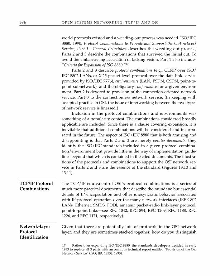
world protocols existed and a weeding-out process was needed. ISO/IEC8880: 1990, Protocol Combinations to Provide and Support the OSI networkService, Part 1—General Principles, describes the weeding-out process;Parts 2 and 3 describe the combinations that survived the initial cut. Toavoid the embarrassing accusation of lacking vision, Part 1 also includes“Criteria for Expansion of ISO 8880.”17
Parts 2 and 3 describe protocol combinations (e.g., CLNP over ISO/IEC 8802 LANs, or X.25 packet level protocol over the data link serviceprovided by ISO/IEC 7776), environments (LAN, PSDN, CSDN, point-to-point subnetwork), and the obligatory conformance for a given environ-ment. Part 2 is devoted to provision of the connection-oriented networkservice, Part 3 to the connectionless network service. (In keeping withaccepted practice in OSI, the issue of interworking between the two typesof network service is finessed.)
Inclusion in the protocol combinations and environments wassomething of a popularity contest. The combinations considered broadlyapplicable are included. Since there is a clause covering expansion, it isinevitable that additional combinations will be considered and incorpo-rated in the future. The aspect of ISO/IEC 8880 that is both amusing anddisappointing is that Parts 2 and 3 are merely pointer documents: theyidentify the ISO/IEC standards included in a given protocol combina-tion/environment but provide little in the way of implementation guide-lines beyond that which is contained in the cited documents. The illustra-tions of the protocols and combinations to support the OSI network ser-vice in Parts 2 and 3 are the essence of the standard (Figures 13.10 and13.11).
The TCP/IP equivalent of OSI’s protocol combinations is a series ofmuch more practical documents that describe the mundane but essentialdetails of IP encapsulation and other idiosyncratic behavior associatedwith IP protocol operation over the many network interfaces (IEEE 802LANs, Ethernet, SMDS, FDDI, amateur packet-radio link-layer protocol,point-to-point links—see RFC 1042, RFC 894, RFC 1209, RFC 1188, RFC1226, and RFC 1171, respectively).
Given that there are potentially lots of protocols in the OSI networklayer, and they are sometimes stacked together, how do you distinguish
O P E N S Y S T E M S N E T W O R K I N G : T C P / I P A N D O S I394
TCP/IP ProtocolCombinations
Network-layerProtocolIdentification
17. Rather than expanding ISO/IEC 8880, the standards developers decided in early1993 to replace all 3 parts with an omnibus technical report entitled “Provision of the OSINetwork Service” (ISO/IEC 13532: 1993).
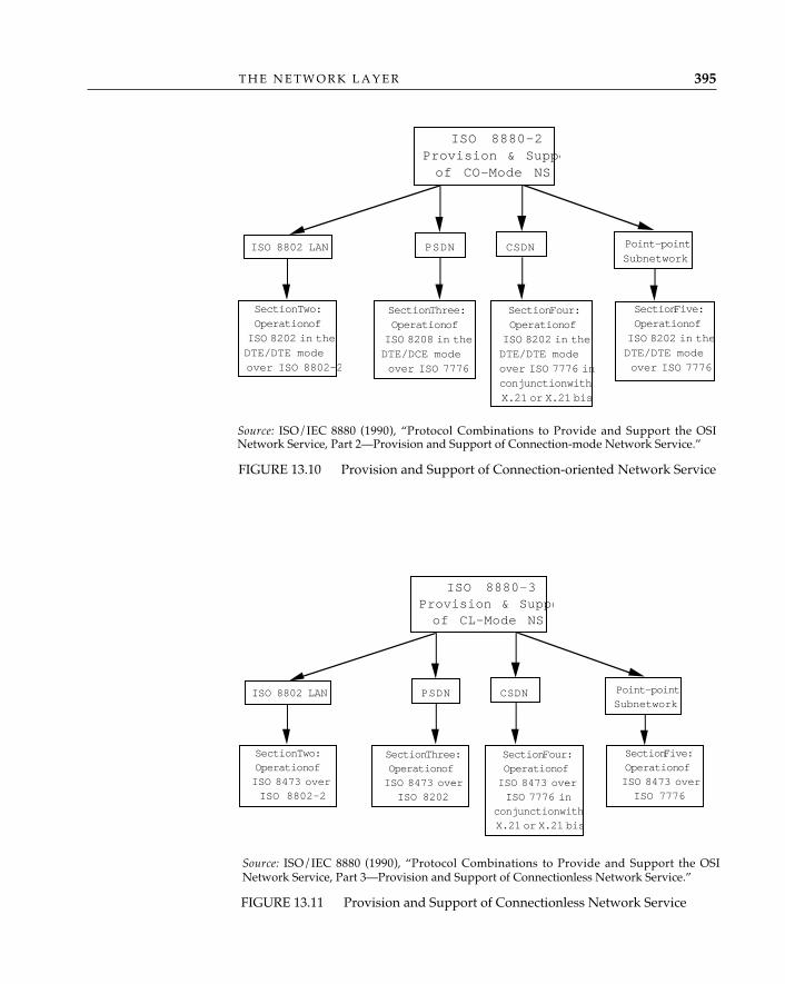
T H E N E T W O R K L A Y E R 395
FIGURE 13.11 Provision and Support of Connectionless Network Service
ISO 8802 LAN PSDN CSDN Point-pointSubnetwork
Section Two:Operation ofISO 8473 overISO 8802-2
Section Three:Operation ofISO 8473 over
ISO 8202
Section Four:Operation ofISO 8473 overISO 7776 in
conjunction withX.21 or X.21 bis
Section Five:Operation ofISO 8473 overISO 7776
ISO 8880-3Provision & Suppoof CL-Mode NS
Source: ISO/IEC 8880 (1990), “Protocol Combinations to Provide and Support the OSINetwork Service, Part 3—Provision and Support of Connectionless Network Service.”
Source: ISO/IEC 8880 (1990), “Protocol Combinations to Provide and Support the OSINetwork Service, Part 2—Provision and Support of Connection-mode Network Service.”
FIGURE 13.10 Provision and Support of Connection-oriented Network Service
ISO 8802 LAN PSDN CSDN Point-pointSubnetwork
Section Two:Operation of
ISO 8202 in theDTE/DTE modeover ISO 8802-2
Section Three:Operation ofISO 8208 in theDTE/DCE modeover ISO 7776
Section Four:Operation ofISO 8202 in theDTE/DTE modeover ISO 7776 inconjunction withX.21 or X.21 bis
Section Five:Operation ofISO 8202 in theDTE/DTE modeover ISO 7776
ISO 8880-2Provision & Suppoof CO-Mode NS
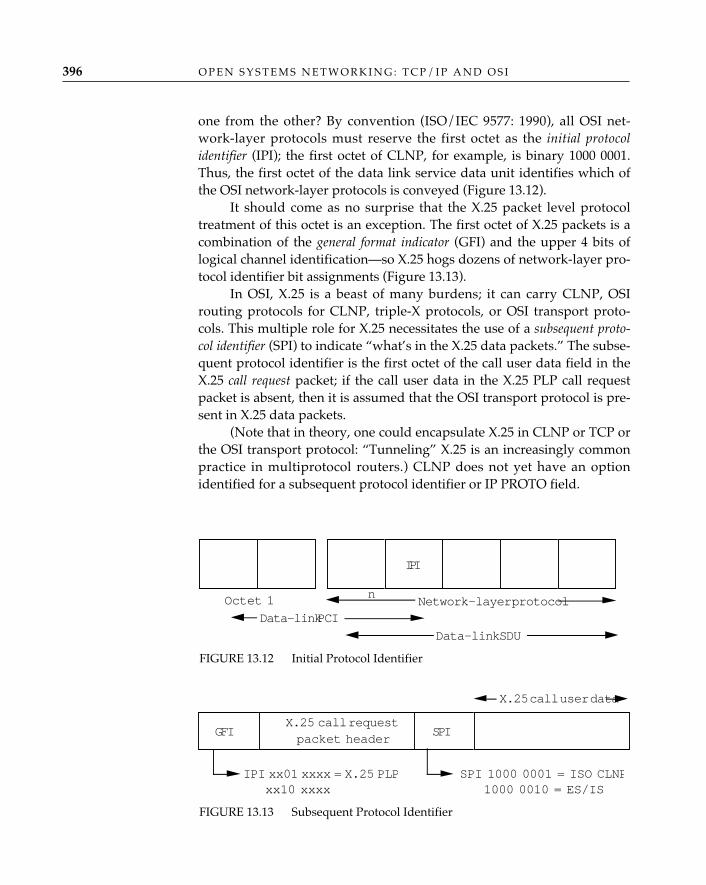
one from the other? By convention (ISO/IEC 9577: 1990), all OSI net-work-layer protocols must reserve the first octet as the initial protocolidentifier (IPI); the first octet of CLNP, for example, is binary 1000 0001.Thus, the first octet of the data link service data unit identifies which ofthe OSI network-layer protocols is conveyed (Figure 13.12).
It should come as no surprise that the X.25 packet level protocoltreatment of this octet is an exception. The first octet of X.25 packets is acombination of the general format indicator (GFI) and the upper 4 bits oflogical channel identification—so X.25 hogs dozens of network-layer pro-tocol identifier bit assignments (Figure 13.13).
In OSI, X.25 is a beast of many burdens; it can carry CLNP, OSIrouting protocols for CLNP, triple-X protocols, or OSI transport proto-cols. This multiple role for X.25 necessitates the use of a subsequent proto-col identifier (SPI) to indicate “what’s in the X.25 data packets.” The subse-quent protocol identifier is the first octet of the call user data field in theX.25 call request packet; if the call user data in the X.25 PLP call requestpacket is absent, then it is assumed that the OSI transport protocol is pre-sent in X.25 data packets.
(Note that in theory, one could encapsulate X.25 in CLNP or TCP orthe OSI transport protocol: “Tunneling” X.25 is an increasingly commonpractice in multiprotocol routers.) CLNP does not yet have an optionidentified for a subsequent protocol identifier or IP PROTO field.
O P E N S Y S T E M S N E T W O R K I N G : T C P / I P A N D O S I396
FIGURE 13.12 Initial Protocol Identifier
IPI
Octet 1 Network-layer protocolData-link PCI
Data-link SDU
n
GFI SPIX.25 call requestpacket header
IPI xx01 xxxx = X.25 PLPxx10 xxxx
SPI 1000 0001 = ISO CLNP1000 0010 = ES/IS
X.25 call user data
FIGURE 13.13 Subsequent Protocol Identifier
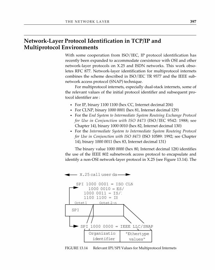
Network-Layer Protocol Identification in TCP/IP andMultiprotocol Environments
With some cooperation from ISO/IEC, IP protocol identification hasrecently been expanded to accommodate coexistence with OSI and othernetwork-layer protocols on X.25 and ISDN networks. This work obso-letes RFC 877. Network-layer identification for multiprotocol internetscombines the scheme described in ISO/IEC TR 9577 and the IEEE sub-network access protocol (SNAP) technique.
For multiprotocol internets, especially dual-stack internets, some ofthe relevant values of the initial protocol identifier and subsequent pro-tocol identifier are :
• For IP, binary 1100 1100 (hex CC, Internet decimal 204)• For CLNP, binary 1000 0001 (hex 81, Internet decimal 129)• For the End System to Intermediate System Routeing Exchange Protocol
for Use in Conjunction with ISO 8473 (ISO/IEC 9542: 1988; seeChapter 14), binary 1000 0010 (hex 82, Internet decimal 130)
• For the Intermediate System to Intermediate System Routeing Protocolfor Use in Conjunction with ISO 8473 (ISO 10589: 1992; see Chapter14), binary 1000 0011 (hex 83, Internet decimal 131)
The binary value 1000 0000 (hex 80, Internet decimal 128) identifiesthe use of the IEEE 802 subnetwork access protocol to encapsulate andidentify a non-OSI network-layer protocol in X.25 (see Figure 13.14). The
T H E N E T W O R K L A Y E R 397
X.25 call user dat
SPI 1000 0001 = ISO CLN 1000 0010 = ES/
SPI
1000 0011 = IS/I1100 1100 = IP
Organizationidentifier
"Ethertypevalues"
SPI 1000 0000 = IEEE LLC/SNAP
Octet 1 Octet 2-n
FIGURE 13.14 Relevant IPI/SPI Values for Multiprotocol Internets
IEEE 802 SNAP is a five-octet header consisting of an organization identifi-er, which is set to the value of the Internet Ethernet address block num-ber (see RFC 1340, Assigned Numbers), and the ethertype value that identi-fies the encapsulated protocol (e.g., IP, ARP).
Network Layer AddressesNetwork-layer addresses identify the hosts (end systems) attached
to TCP/IP and OSI networks. IP and OSI network service access point(NSAP) addresses share several common attributes:
• They are globally unique—address administrations and policiesexist to ensure that no two host machines use the same networkaddress.
• They accommodate (and prescribe) hierarchies, which enablegroups of hosts to be associated with a specific domain (and possi-bly subdomains within that domain).
• They convey information that is used to determine routes betweenhosts, across potentially many (sub)networks.
Network addressing in the Internet accommodates a single networkservice; network addressing in OSI must accommodate not only multiplenetwork services but a very large number of public numbering and pri-vate addressing plans. In the following subsections, readers should con-sider how Internet and OSI network addressing are influenced by differ-ences in scope and in the expectations that have been imposed on them.
The Internet network address is more commonly called the “IP address.”It consists of 32 bits, some of which are allocated to a high-order network-number part and the remainder of which are allocated to a low-order host-number part. The distribution of bits—how many form the network num-ber, and how many are therefore left for the host number—can be donein one of three different ways, giving three different classes of IP address(see Figure 13.15).18
The network number identifies a real subnetwork, and the hostnumber identifies a physical interface to that subnetwork. Whereas theOSI network-layer address identifies the abstract service access point
O P E N S Y S T E M S N E T W O R K I N G : T C P / I P A N D O S I398
Internet (IP)Addresses
18. In fact, there are two other IP address classes which are not discussed here; class-D addresses,which begin with the bit pattern 1110, are reserved for IP multicasting, and class-E addresses, whichbegin with the bit pattern 1111, are reserved for experimental use.
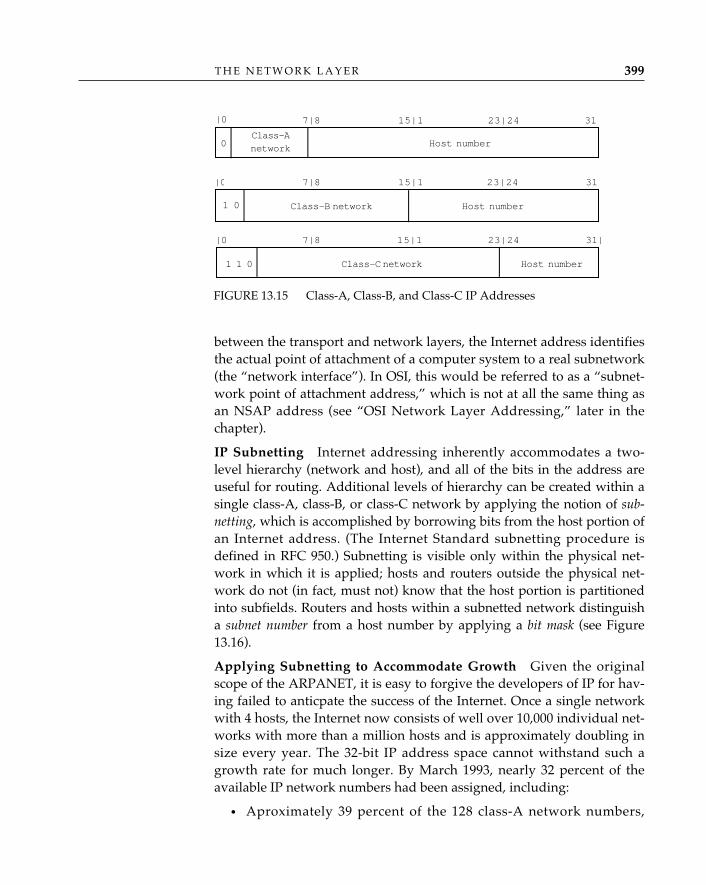
between the transport and network layers, the Internet address identifiesthe actual point of attachment of a computer system to a real subnetwork(the “network interface”). In OSI, this would be referred to as a “subnet-work point of attachment address,” which is not at all the same thing asan NSAP address (see “OSI Network Layer Addressing,” later in thechapter).
IP Subnetting—Internet addressing inherently accommodates a two-level hierarchy (network and host), and all of the bits in the address areuseful for routing. Additional levels of hierarchy can be created within asingle class-A, class-B, or class-C network by applying the notion of sub-netting, which is accomplished by borrowing bits from the host portion ofan Internet address. (The Internet Standard subnetting procedure isdefined in RFC 950.) Subnetting is visible only within the physical net-work in which it is applied; hosts and routers outside the physical net-work do not (in fact, must not) know that the host portion is partitionedinto subfields. Routers and hosts within a subnetted network distinguisha subnet number from a host number by applying a bit mask (see Figure13.16).
Applying Subnetting to Accommodate Growth—Given the originalscope of the ARPANET, it is easy to forgive the developers of IP for hav-ing failed to anticpate the success of the Internet. Once a single networkwith 4 hosts, the Internet now consists of well over 10,000 individual net-works with more than a million hosts and is approximately doubling insize every year. The 32-bit IP address space cannot withstand such agrowth rate for much longer. By March 1993, nearly 32 percent of theavailable IP network numbers had been assigned, including:
• Aproximately 39 percent of the 128 class-A network numbers,
T H E N E T W O R K L A Y E R 399
FIGURE 13.15 Class-A, Class-B, and Class-C IP Addresses
0Class-Anetwork Host number
1 0 Class-B network Host number
Host number1 1 0 Class-C network
|0 7|8 3115|1 23|24
|0
7|8
7|8
|0 15|1
15|1 23|24
23|24
31
31|
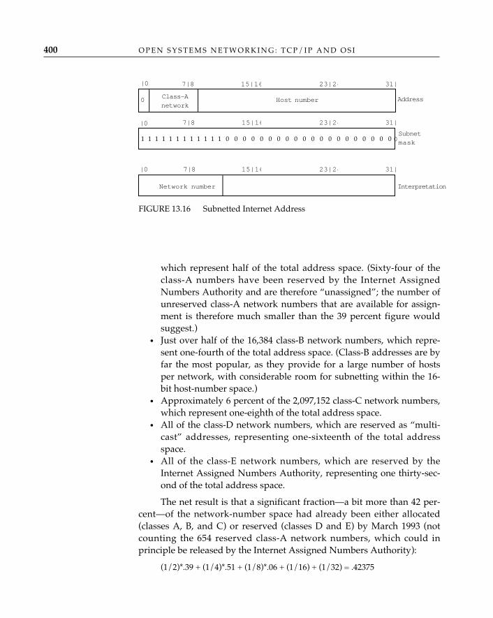
which represent half of the total address space. (Sixty-four of theclass-A numbers have been reserved by the Internet AssignedNumbers Authority and are therefore “unassigned”; the number ofunreserved class-A network numbers that are available for assign-ment is therefore much smaller than the 39 percent figure wouldsuggest.)
• Just over half of the 16,384 class-B network numbers, which repre-sent one-fourth of the total address space. (Class-B addresses are byfar the most popular, as they provide for a large number of hostsper network, with considerable room for subnetting within the 16-bit host-number space.)
• Approximately 6 percent of the 2,097,152 class-C network numbers,which represent one-eighth of the total address space.
• All of the class-D network numbers, which are reserved as “multi-cast” addresses, representing one-sixteenth of the total addressspace.
• All of the class-E network numbers, which are reserved by theInternet Assigned Numbers Authority, representing one thirty-sec-ond of the total address space.
The net result is that a significant fraction—a bit more than 42 per-cent—of the network-number space had already been either allocated(classes A, B, and C) or reserved (classes D and E) by March 1993 (notcounting the 654 reserved class-A network numbers, which could inprinciple be released by the Internet Assigned Numbers Authority):
(1/2)*.39 + (1/4)*.51 + (1/8)*.06 + (1/16) + (1/32) = .42375
O P E N S Y S T E M S N E T W O R K I N G : T C P / I P A N D O S I400
FIGURE 13.16 Subnetted Internet Address
0 Class-Anetwork
Host number
7|8 31|15|16
Address
Subnetmask1 1 1 1 1 1 1 1 1 1 1 1 0 0 0 0 0 0 0 0 0 0 0 0 0 0
23|24
|0
InterpretationNetwork number
|0
|0 7|8 15|16 23|24 31|
7|8 15|16 23|24 31|
1 1 1 1 1 1 1 1 1 1 1 1 0 0 0 0 0 0 0 0 0 0 0 0 0 0 0 0 0 0 0 0
Clearly, we cannot continue to assign new IP network numbers atan annual growth rate of 100 percent for much longer! Fortunately, thereappears to be at least a short-term solution to the problem, based on theobservation that the depletion of the IP network-number space has beenartificially accelerated by a mismatch between the number of hosts pernetwork allowed by the fixed class-B and class-C partitions (64K and 8K,respectively) and the number of hosts that are typically attached to real-world networks (something in between, but often much smaller than64K). One way to add years to the life of the existing IP address space isto extend the practice of IP subnetting and take advantage of the largenumber of unassigned class-C network numbers. An RFC in progressrecommends that the rigidly fixed octet boundaries that define the threeclasses of IP address be broken (ignored) and that more flexible bit-levelmasks be used to distinguish the network number from the host number.This “classless” interdomain routing (CIDR) strategy would permitblocks of contiguous class-C network numbers to be assigned to sites thatwould ordinarily need a class-B network number (to accommodate morethan 256 hosts). Although this strategy clearly does not increase the totalsupply of network numbers, it encourages more efficient (denser) use ofthe host-number space associated with each network number (or set ofcontiguous network numbers), thereby slowing the rate at which newnetwork numbers must be assigned.
By itself, the assignment of a block of class-C network numbersrather than a single class-B network number creates a problem that ispotentially much worse than the problem it attempts to solve: if routersmust advertise each of the class-C network numbers individually, the“not enough addresses” problem has been solved at the expense of creat-ing a new “too many routes” problem. Internet routers cannot efficientlymaintain the very large routing tables that would result from the adver-tisement of many tens of thousands of networks. The classless interdo-main routing scheme therefore requires the development and deploy-ment of interdomain routing protocols that summarize (“aggregate”)routing advertisements, so that a single routing table entry can be main-tained for a set of networks that share a common IP network-numberprefix and routing metrics (see Chapter 14). Rather than maintaining anentry for each network number (as would be the case with current inter-domain protocols), sites with multiple contiguous class-C network num-bers would be routed in the interdomain system using a single routingtable entry.
It is in fact necessary for this aggregation to occur recursively at thetransit routing domain boundaries (for example, the boundaries between
T H E N E T W O R K L A Y E R 401
the National Science Foundation backbone NSFnet and the NSFnetregionals; between NSFnet and the European backbone network EBONE;or between the Nordic regional network NORDUnet and the commercialnetwork Alternet) in order to arrest the growth of routing tables in transitdomain routers. This requires greater coordination in the assignment ofnetwork numbers: sites that are topologically “close” with respect totransit domain routing must be allocated network-number blocks withadjacent prefixes. Making intelligent choices when assigning networknumbers in this way is likely to be possible (if it is possible at all) only ifthe assignment authority is delegated to the organizations that areresponsible for coordinating international and interorganizational rout-ing. Classless interdomain routing may not be effective if network-num-ber assignment remains centralized.
Classless interdomain routing will require Internet network opera-tors to use one of the two interdomain routing protocols that currentlysupport variable-length subnet masks (see Chapter 14, “InterdomainRouting”) in place of the popular “exterior gateway protocols” (seeChapter 14, “Interdomain Routing in TCP/IP”). It will also be the casethat networks that do not default external routes to a major transit net-work will be unable to continue using an intradomain routing protocolthat does not support variable-length subnet masks, because incomingroute advertisements representing aggregated sets of network addresseswould have to be expanded, resulting in what would eventually beunsupportable increases in the amount of router memory required tostore all of the routes individually.
The expected “time to impact” for classless interdomain routing istwo to three years, given the time it takes to implement and deploy anew routing protocol and the network-operation adjustments that will berequired. Routing experts do not agree on the question of whether class-less interdomain routing buys enough time to wait for a completely newInternet routing and addressing architecture or only breathing room forthe deployment of a near-term functionally equivalent replacement forIP. However, there is general agreement that classless interdomain rout-ing is worth doing in either case, and the Internet Engineering SteeringGroup has begun the process of approving an Internet standard that willmandate the use of classless interdomain routing in the Internet.
A Real-World Example of IP Address—Internet address data structuresmay be represented in a UNIX environment in the following manner:
typedef char in–addr[4] /* 4-octet IP address */struct sockaddr {
O P E N S Y S T E M S N E T W O R K I N G : T C P / I P A N D O S I402
short sa_family; /* address family, e.g., internet */char sa_data (14); /* space for the address */
}struct sockaddr_in {
short sin_family; /* address family is internet */u_short sin_port; /* the internet port */in_addr sin_addr; /* the IP address a.b.c.d */char sin_zero[8]; /* unused */
}
Like every networking architecture that preceded it, OSI neededaddresses to identify hosts and gateways so that routes could be comput-ed and packets could be forwarded. By the time OSI network-layeraddressing was considered, however, OSI had already succumbed to apolitical compromise that demanded the accommodation of multiplesolutions to providing the network service. By the rules of this bargain,X.25 public data networks, X.21 circuit-switched data networks, andCLNP-based enterprise networks were all equally capable of providing(and all equally entitled to provide) the OSI network service. This all buteliminated the opportunity to design a logical network-layer addressingscheme from scratch; the common carriers providing X.25 packet-switch-ing service or X.21 circuit-switched service naturally wished to continueto use the CCITT X.121 numbering plan for public data networks or theCCITT E.163 numbering plan for the public switched telephone network,and simply call the X.121 or E.163 numbers “OSI NSAP addresses.”Integrated services digital networks (ISDNs) would use the CCITT E.164Numbering Plan for the ISDN Era; these numbers, too, had to be OSINSAP addresses.19 CLNP-based networks, on the other hand, wouldbenefit from NSAP addresses structured like the IP addresses of theInternet, so that routing topology information could be derived from thecomposition of the address and efficient routes could be computed. TheOSI standards community briefly considered subsuming all OSI net-work-layer addressing under the administration of one of the existingnumbering plans, but the existence of a half-dozen eager candidates forthis role put a quick end to this alternative. After protracted debate, itwas finally agreed that the only way forward was to “embrace them all”in a grand compromise that gave the appropriate recognition and statusto each of the contenders.
Hemrick (1985) provides an excellent historical account of the
T H E N E T W O R K L A Y E R 403
19. Addressing plans such as these are sensitive first to administrative needs, and therouting information that can be derived from such addresses is typically limited to geo-graphic locality.
OSI NetworkLayer Addressing
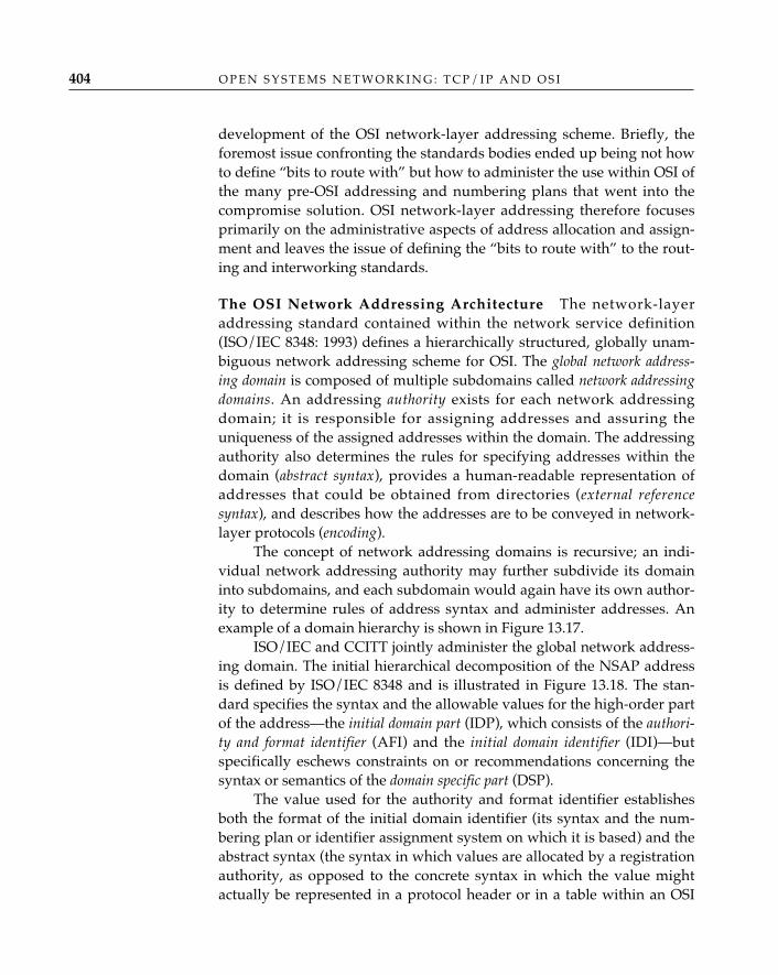
development of the OSI network-layer addressing scheme. Briefly, theforemost issue confronting the standards bodies ended up being not howto define “bits to route with” but how to administer the use within OSI ofthe many pre-OSI addressing and numbering plans that went into thecompromise solution. OSI network-layer addressing therefore focusesprimarily on the administrative aspects of address allocation and assign-ment and leaves the issue of defining the “bits to route with” to the rout-ing and interworking standards.
The OSI Network Addressing Architecture—The network-layeraddressing standard contained within the network service definition(ISO/IEC 8348: 1993) defines a hierarchically structured, globally unam-biguous network addressing scheme for OSI. The global network address-ing domain is composed of multiple subdomains called network addressingdomains. An addressing authority exists for each network addressingdomain; it is responsible for assigning addresses and assuring theuniqueness of the assigned addresses within the domain. The addressingauthority also determines the rules for specifying addresses within thedomain (abstract syntax), provides a human-readable representation ofaddresses that could be obtained from directories (external referencesyntax), and describes how the addresses are to be conveyed in network-layer protocols (encoding).
The concept of network addressing domains is recursive; an indi-vidual network addressing authority may further subdivide its domaininto subdomains, and each subdomain would again have its own author-ity to determine rules of address syntax and administer addresses. Anexample of a domain hierarchy is shown in Figure 13.17.
ISO/IEC and CCITT jointly administer the global network address-ing domain. The initial hierarchical decomposition of the NSAP addressis defined by ISO/IEC 8348 and is illustrated in Figure 13.18. The stan-dard specifies the syntax and the allowable values for the high-order partof the address—the initial domain part (IDP), which consists of the authori-ty and format identifier (AFI) and the initial domain identifier (IDI)—butspecifically eschews constraints on or recommendations concerning thesyntax or semantics of the domain specific part (DSP).
The value used for the authority and format identifier establishesboth the format of the initial domain identifier (its syntax and the num-bering plan or identifier assignment system on which it is based) and theabstract syntax (the syntax in which values are allocated by a registrationauthority, as opposed to the concrete syntax in which the value mightactually be represented in a protocol header or in a table within an OSI
O P E N S Y S T E M S N E T W O R K I N G : T C P / I P A N D O S I404
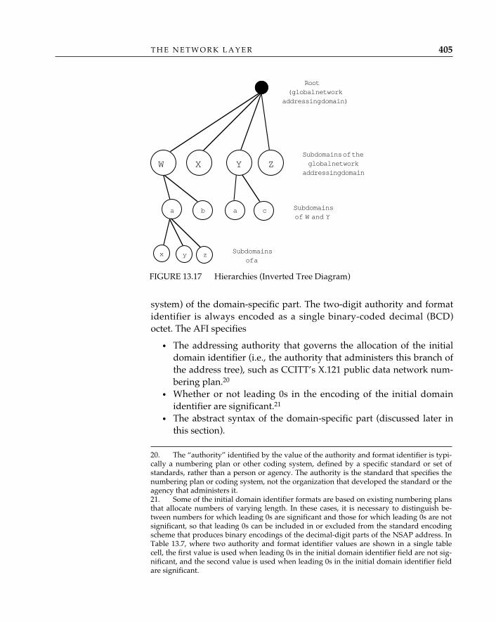
system) of the domain-specific part. The two-digit authority and formatidentifier is always encoded as a single binary-coded decimal (BCD)octet. The AFI specifies
• The addressing authority that governs the allocation of the initialdomain identifier (i.e., the authority that administers this branch ofthe address tree), such as CCITT’s X.121 public data network num-bering plan.20
• Whether or not leading 0s in the encoding of the initial domainidentifier are significant.21
• The abstract syntax of the domain-specific part (discussed later inthis section).
T H E N E T W O R K L A Y E R 405
20. The “authority” identified by the value of the authority and format identifier is typi-cally a numbering plan or other coding system, defined by a specific standard or set ofstandards, rather than a person or agency. The authority is the standard that specifies thenumbering plan or coding system, not the organization that developed the standard or theagency that administers it.21. Some of the initial domain identifier formats are based on existing numbering plansthat allocate numbers of varying length. In these cases, it is necessary to distinguish be-tween numbers for which leading 0s are significant and those for which leading 0s are notsignificant, so that leading 0s can be included in or excluded from the standard encodingscheme that produces binary encodings of the decimal-digit parts of the NSAP address. InTable 13.7, where two authority and format identifier values are shown in a single tablecell, the first value is used when leading 0s in the initial domain identifier field are not sig-nificant, and the second value is used when leading 0s in the initial domain identifier fieldare significant.
FIGURE 13.17 Hierarchies (Inverted Tree Diagram)
Root(global network
addressing domain)
W X Y ZSubdomains of theglobal network
addressing domain
a b a c Subdomainsof W and Y
x y z Subdomainsof a
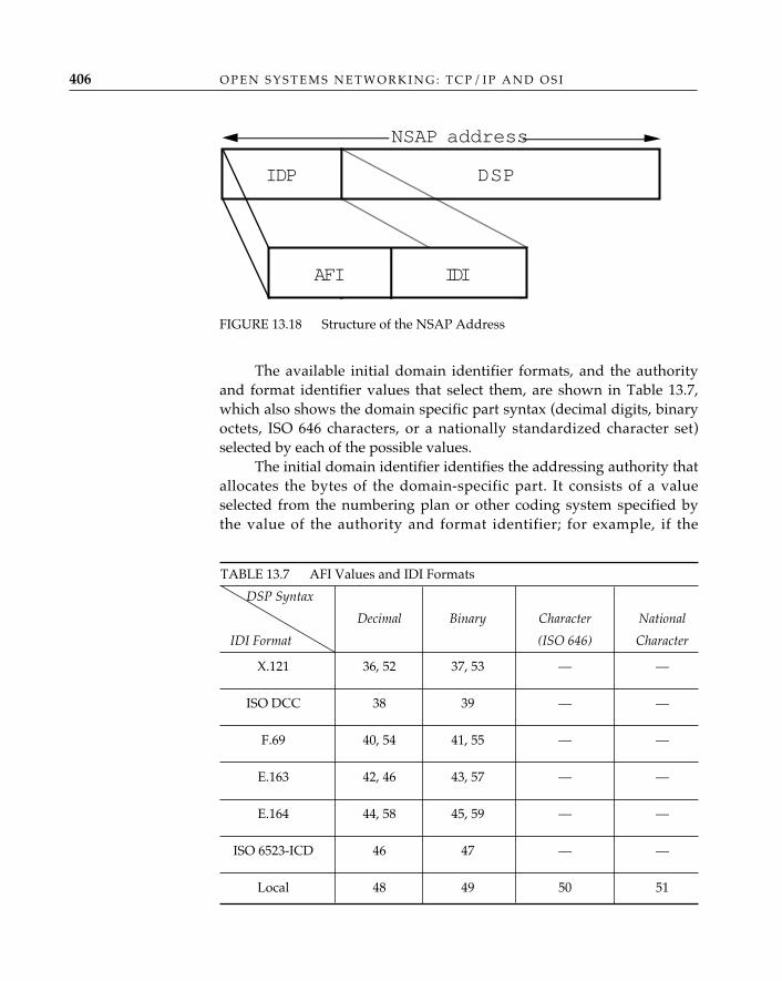
The available initial domain identifier formats, and the authorityand format identifier values that select them, are shown in Table 13.7,which also shows the domain specific part syntax (decimal digits, binaryoctets, ISO 646 characters, or a nationally standardized character set)selected by each of the possible values.
The initial domain identifier identifies the addressing authority thatallocates the bytes of the domain-specific part. It consists of a valueselected from the numbering plan or other coding system specified bythe value of the authority and format identifier; for example, if the
O P E N S Y S T E M S N E T W O R K I N G : T C P / I P A N D O S I406
FIGURE 13.18 Structure of the NSAP Address
DSPIDP
AFI IDI
NSAP address
AFI IDI
TABLE 13.7 AFI Values and IDI Formats
DSP Syntax
Decimal Binary Character National
IDI Format (ISO 646) Character
X.121 36, 52 37, 53 — —
ISO DCC 38 39 — —
F.69 40, 54 41, 55 — —
E.163 42, 46 43, 57 — —
E.164 44, 58 45, 59 — —
ISO 6523-ICD 46 47 — —
Local 48 49 50 51
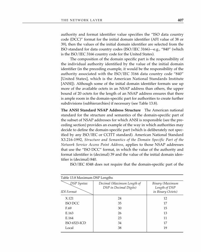
authority and format identifier value specifies the “ISO data countrycode (DCC)” format for the initial domain identifier (AFI value of 38 or39), then the values of the initial domain identifier are selected from theISO standard for data country codes (ISO/IEC 3166)—e.g., “840” (whichis the ISO/IEC 3166 country code for the United States).
The composition of the domain specific part is the responsibility ofthe individual authority identified by the value of the initial domainidentifier (in the preceding example, it would be the responsibility of theauthority associated with the ISO/IEC 3166 data country code “840”[United States], which is the American National Standards Institute[ANSI]). Although some of the initial domain identifier formats use upmore of the available octets in an NSAP address than others, the upperbound of 20 octets for the length of an NSAP address ensures that thereis ample room in the domain-specific part for authorities to create furthersubdivisions (subhierarchies) if necessary (see Table 13.8).
The ANSI Standard NSAP Address Structure—The American nationalstandard for the structure and semantics of the domain-specific part ofthe subset of NSAP addresses for which ANSI is responsible (see the pre-ceding section) provides an example of the way in which authorities maydecide to define the domain-specific part (which is deliberately not spec-ified by any ISO/IEC or CCITT standard). American National StandardX3.216-1992, Structure and Semantics of the Domain Specific Part of theNetwork Service Access Point Address, applies to those NSAP addressesthat use the “ISO DCC” format, in which the value of the authority andformat identifier is (decimal) 39 and the value of the initial domain iden-tifier is (decimal) 840.
ISO/IEC 8348 does not require that the domain-specific part of the
T H E N E T W O R K L A Y E R 407
Table 13.8 Maximum DSP Lengths
DSP Syntax Decimal (Maximum Length of Binary (Maximum DSP in Decimal Digits) Length of DSP
IDI Format in Binary Octets)
X.121 24 12ISO DCC 35 17F.69 30 15E.163 26 13E.164 23 11ISO 6523-ICD 34 17Local 38 19
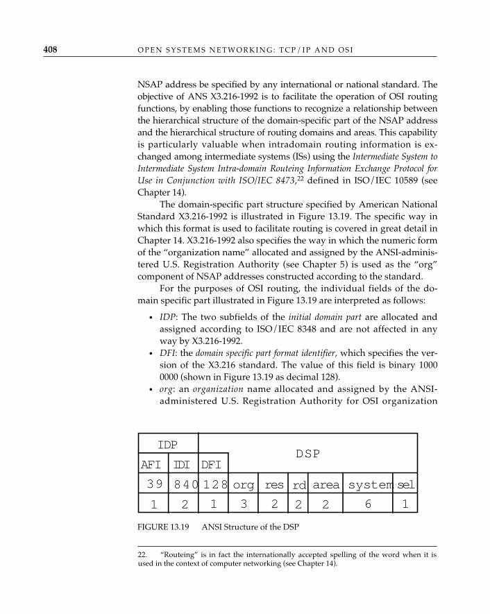
NSAP address be specified by any international or national standard. Theobjective of ANS X3.216-1992 is to facilitate the operation of OSI routingfunctions, by enabling those functions to recognize a relationship betweenthe hierarchical structure of the domain-specific part of the NSAP addressand the hierarchical structure of routing domains and areas. This capabilityis particularly valuable when intradomain routing information is ex-changed among intermediate systems (ISs) using the Intermediate System toIntermediate System Intra-domain Routeing Information Exchange Protocol forUse in Conjunction with ISO/IEC 8473,22 defined in ISO/IEC 10589 (seeChapter 14).
The domain-specific part structure specified by American NationalStandard X3.216-1992 is illustrated in Figure 13.19. The specific way inwhich this format is used to facilitate routing is covered in great detail inChapter 14. X3.216-1992 also specifies the way in which the numeric formof the “organization name” allocated and assigned by the ANSI-adminis-tered U.S. Registration Authority (see Chapter 5) is used as the “org”component of NSAP addresses constructed according to the standard.
For the purposes of OSI routing, the individual fields of the do-main specific part illustrated in Figure 13.19 are interpreted as follows:
• IDP: The two subfields of the initial domain part are allocated andassigned according to ISO/IEC 8348 and are not affected in anyway by X3.216-1992.
• DFI: the domain specific part format identifier, which specifies the ver-sion of the X3.216 standard. The value of this field is binary 10000000 (shown in Figure 13.19 as decimal 128).
• org: an organization name allocated and assigned by the ANSI-administered U.S. Registration Authority for OSI organization
O P E N S Y S T E M S N E T W O R K I N G : T C P / I P A N D O S I408
FIGURE 13.19 ANSI Structure of the DSP
IDPDSP
AFI IDI
39
1
840
2
DFI
1
org
3
res
2
area
2
sel
1
system
62
rd128
22. “Routeing” is in fact the internationally accepted spelling of the word when it isused in the context of computer networking (see Chapter 14).
names (see “The USA Registration Authority,” in Chapter 5). TheU.S. Registration Authority allocates numeric organization namesas decimal numeric values. The value of this field is the binaryvalue obtained by encoding the numeric organization name accord-ing to the “network address encoding” procedure defined inISO/IEC 8348.
• res: reserved. The value of this field is 0.• rd: the portion of the NSAP address up to and including the “rd”
(routing domain) field constitutes a routing domain prefix, whichsummarizes information about some or all of the area addresseswithin a routing domain. This enables the border intermediate sys-tems in a routing domain to advertise one or more prefixes, in lieuof an enumeration of the corresponding individual area addresses,for the purposes of interdomain routing information exchange (seeChapter 14).
• area: an identifier for the area within a routing domain to which theNSAP address belongs. The portion of the NSAP address up to andincluding the area field constitutes an area address in the sense inwhich the term is used (and defined) by ISO/IEC 10589. In theISO/IEC 10589 context, level-1 intermediate systems report onlyarea addresses, and level-2 intermediate systems exchange amongthemselves only area address information (and thus route only onthe basis of area addresses).
• system: an identifier for the individual end system (in the case of anNSAP address) or intermediate system (in the case of a network enti-ty title) with which the NSAP or network entity title is associated.The internal structure, value, and meaning of the system field arenot specified or constrained by X3.216-1992.
• sel: the “NSAP selector,” which serves to differentiate multipleNSAP addresses associated with the same network entity. Thevalue of the sel field in a network entity title is 0.
A Real-World Example of OSI NSAP Addresses—What in the realworld are NSAP addresses? In UNIX implementations, under a socketaddress family “ISO,” an NSAP address could be viewed as the equiva-lent of a TCP/IP “Internet address.” As described in Chapter 12, the Cdata structure sockaddr, OSI-style, looks like this (again, from ARGO 1.0RENO):
struct sockaddr {short sa_family; /* address family, ISO */char sa_data (14); /* space for the address */}
T H E N E T W O R K L A Y E R 409
struct sockaddr_iso {short siso_family; /* address family is iso */u_short siso_tsuffix; /* the TSAP Address */iso_addr siso_addr; /* the NSAP Address */char siso_zero[2]; /* unused */}
Many systems, especially routers, will find it necessary to accom-modate multiple NSAP address formats. These might be encoded in thefollowing manner:
struct iso_addr {u_char isoa_afi; /* authority/format identifier */union {
struct addr_37 addr_37; /* x.121 */struct addr_39 addr_ansi; /* ISO DCC IDI *struct addr_47 addr_6523icd; /* ISO 6523 ICD*/
}isoa_u; u_char
isoa_len; /* length */
in which “addr_ansi” from the earlier example would appear as follows:
struct addr_ansi {u_char ansi_dfi; /* DSP format identifier */char ansi_org (3); /* organization code */char reservd (2); /* not used yet */char domain (2); /* routing domain */char area (2); /* area within domain */char systemid (6); /* possibly a 48-bit
IEEE 802 MAC address */u_char NSAPsel; /* NSAP selector */
};
OSI NSAP Addresses in the Internet—With so many NSAP addressingformats to choose from, which should be used in a multiprotocol Internetsupporting (at least) OSI and TCP/IP? Guidelines for OSI NSAP Allocationin the Internet (RFC 1237) describes the administrative requirements forobtaining and allocating NSAP addresses and for distributing the assign-ment authority among the Internet’s backbone and midlevel networks. Italso explains how to construct and assign the various parts of the NSAPaddress to achieve efficient OSI and dual-stack (OSI and IP) routing andhow to apply NSAP addressing to achieve the OSI equivalents of existingIP topological entities—backbones, regionals, and site and campus net-works—in the Internet.
O P E N S Y S T E M S N E T W O R K I N G : T C P / I P A N D O S I410
ConclusionBecause of the inability of the OSI standards community to decide be-tween a network-centric or host-centric model of global networking, theOSI network layer is really several layers trying to look like one, as if forthe sake of architectural appearances. The Internal Organization of theNetwork Layer is a convenient fig leaf, but the international networkingcommunity would be much better served by a forthright recognition ofthe internet/subnet split within the network layer. The TCP/IP archi-tects avoided this problem entirely—their network layer is actuallycalled the “internet” layer, and it sits on top of clearly distinguished sub-networks (“network interfaces”).
Although this is often characterized as a “failure” on the partof the OSI standards developers, it is important to realize that
the host-centric/network-centric conflict was not played out in purely abstractterms. Network-centric arguments make more sense in the real-world context ofnational regulation, monopolistic common carriers, and the economics of publicdata networks and their tariffs. The host-centric argument has always been thatdiversity—in networks as in everything else— is an inescapable fact of life andthat no amount of regulating (or standards making) can or should limit therange of choices from the menu of networking technologies that makes internet-working essential. The conflict has by no means been resolved within OSI, butfew people today would bet on anything other than internetworking as the mostlikely model of the future global data network.
The apparent incompatibility of the connection-oriented and con-nectionless network services in OSI is not an interworking problem andwould not be solved by the invention of a magic gateway that could con-vert one type of service into the other. It is a fundamental architecturalproblem, reflecting two very different models for interconnecting aworld’s worth of networked hosts. The TCP/IP community has been for-tunate to avoid this issue long enough to firmly establish TCP/IP’s con-nectionless-internetworking architecture as the unchallenged centerpieceof the global Internet.
✧AHA✧
T H E N E T W O R K L A Y E R 411
“R—oo‘•ting” is what fans do at a football game, what pigs do for trufflesunder oak trees in the Vaucluse, and what nursery workers intent onpropagation do to cuttings from plants. “Rou´•ting” is how one creates abeveled edge on a tabletop or sends a corps of infantrymen into full-scale, disorganized retreat. Either pronunciation is correct for routing,which refers to the process of discovering, selecting, and employingpaths from one place to another (or to many others) in a network.
The British prefer the spelling routeing, perhaps to distin-guish what happens in networks from what happened to the
British in New Orleans in 1814. Since the Oxford English Dictionary ismuch heavier than any dictionary of American English, British English generallyprevails in the documents produced by ISO and CCITT; wherefore, most of theinternational standards for routing protocols use the routeing spelling. Sincethis spelling would be unfamiliar to many readers, we use routing in this book,with apologies to our friends in the British Standards Institute.
A simple definition of routing is “learning how to get from here tothere.”1 In some cases, the term routing is used in a very strict sense torefer only to the process of obtaining and distributing information (“learn-ing”), but not to the process of using that information to actually get
✧AHA✧
14 ROUTING
413
1. This is an application of the classic definition of a route by Schoch (see Chapter 5),augmented by Radia Perlman’s (1992a) very practical observation that routes are bothsource- and destination-dependent: knowing how to get there isn’t enough; you have toknow where you are starting from (“here”) as well as where you are going (“there”).
from one place to another (for which a different term, forwarding, is re-served). Since it is difficult to grasp the usefulness of information that isacquired but never used, this chapter employs the term routing to refer ingeneral to all the things that are done to discover and advertise pathsfrom here to there and to actually move packets from here to there whennecessary. The distinction between routing and forwarding is preservedin the formal discussion of the functions performed by OSI end systemsand intermediate systems, in which context the distinction is meaningful.
Source Routing and “Hop-by-Hop” RoutingThe routing operations of finding out how to get from here to there, andthen actually getting from here to there, can be done in two (very differ-ent) basic ways. In source routing, all the information about how to getfrom here to there is first collected at the source (“here”), which puts itinto the packets that it launches toward the destination (“there”). The jobof the intervening network (with its collection of links and intermediatesystems) is simply to read the routing information from the packets andact on it faithfully. In hop-by-hop routing, the source is not expected tohave all the information about how to get from here to there; it is suffi-cient for the source to know only how to get to the “next hop” (perhapsan intermediate system to which it has a working link), and for that sys-tem to know how to get to the next hop, and so on until the destination isreached. The job of the intervening network in this case is more compli-cated; it has only the address of the destination (rather than a completespecification of the route by the source) with which to figure out the best“next hop” for each packet.
Consider an example, in which “here” is your home in Hopkinton,Massachusetts (U.S.A.), and “there” is Blueberry Hill Inn in Goshen,Vermont. If you sit down at home with a set of road maps and figure outexactly which roads and highways connect Hopkinton and Goshen, plot-ting the route you will follow along this road to that interchange to thisjunction (etc.), and then get in your car and actually drive along preciselythat route to Blueberry Hill, you are performing source routing: if youwere a packet, an ordered list of identifiers for links (roads) and interme-diate systems (junctions and interchanges) would be encoded in yourprotocol header (see Chapter 13). If, on the other hand, you simply climbinto your car and begin driving, stopping at every intersection to ask di-rections or examine the signposts, you are performing hop-by-hop rout-ing: if you were a packet, the identification of your origin (Hopkinton)
O P E N S Y S T E M S N E T W O R K I N G : T C P / I P A N D O S I414
and final destination (Blueberry Hill) would be encoded in your protocolheader. In the first case, your ability to actually get to Blueberry Hilldepends on the accuracy of the maps you used and whether or not anyof the roads you have selected are closed for repairs; in the second case,it depends on finding enough information at every intersection to enableyou to pick the right road to follow to the next.
For the most part, routing in OSI and TCP/IP networks today ishop-by-hop. Source routing has recently emerged as an important com-ponent of a new set of routing capabilities (for both OSI and TCP/IP net-works) that support complex policies governing the paths that packets arepermitted to take when more than one organization owns or administersthe equipment and facilities that intervene between “here” and “there.”These issues are, however, beyond the scope of this chapter, which con-centrates on the current hop-by-hop architecture of OSI and TCP/IProuting, and which also omits the very different concerns of routing invirtual-circuit (connection-oriented) networks. For a detailed and com-prehensive description of the theory and practice of routing, includingthe topics that are beyond the scope of this book, readers are encouragedto consult Interconnections: Bridges and Routers (Perlman 1992a).
Routing PrinciplesThe principal criterion of successful routing is, of course, correctness (youdo in fact want to get to Blueberry Hill, not Cranberry Bog), but it is notthe only criterion. You might prefer to take the most direct route (the onethat takes the least time and uses the least fuel), the most reliable route(the one that is not likely to be closed by a heavy snowfall), the mostscenic route (the one that follows pleasant country roads rather thanbusy highways), the least expensive route (the one that follows freewaysrather than toll roads), or the safest route (the one that avoids the army’smissile testing range). In its most general form, optimal routing involvesforwarding a packet from source to destination using the “best” path.What constitutes the “best” path can, of course, become quite a compli-cated question, as this example shows; networks, like the highway sys-tem, have variable costs, transit restrictions, delay characteristics, andresidual error rates, and all of these can be more or less important in thedetermination of what “best” means for a particular source and destina-tion or for a particular packet.
The principal objective of an open systems routing architecture isnot, therefore, to achieve “optimal” routing—such a thing does not exist
R O U T I N G 415
in the abstract. Such an architecture must nevertheless be based on prin-ciples that account for what is happening in the real open systems worldof today and tomorrow, in which computers are being connected to net-works at a rate that more than doubles the number of systems connectedto the worldwide (OSI and TCP/IP) Internet each year. These computerswill be connected using a variety of local, metropolitan, and wide areanetworking technologies; the topology of interconnection will change ascomputers and the links between them are added and deleted; the net-works will cross every conceivable national and international boundary;and the computers and networks will be administered by different orga-nizations, both public and private, each of which may impose rules (poli-cies) governing (and safeguarding) their use.
These observations suggest that an open systems routing architec-ture should
• Scale well• Support many different subnetwork types and multiple qualities of
service• Adapt to topology changes quickly and efficiently (i.e., with mini-
mal overhead and complexity)• Provide controls that facilitate the “safe” interconnection of multi-
ple organizations
It is not likely that the manual administration of static routingtables (the earliest medium for the maintenance of internetwork routes,in which a complete set of fixed routes from each system to every othersystem was periodically—often no more frequently than once a week—loaded into a file on each system) will satisfy these objectives for a net-work connecting more than a few hundred systems. A routing schemefor a large-scale open systems network must be dynamic, adaptive, anddecentralized; be capable of supporting multiple paths offering differenttypes of service; and provide the means to establish “trust, firewalls, andsecurity” across multiple administrations (ISO/IEC TR 9575: 1990).
The architecture of routing in OSI is basically the same as the architectureof routing in other connectionless (datagram) networks, including TCP/IP. As usual, however, the conceptual framework and terminology of OSIare more highly elaborated than those of its roughly equivalent peers,and thus, it is the OSI routing architecture that gets the lion’s share ofattention in this chapter. Keep in mind that most of what is said aboutthe OSI routing architecture applies to hop-by-hop connectionless opensystems routing in general.
O P E N S Y S T E M S N E T W O R K I N G : T C P / I P A N D O S I416
OSI RoutingArchitecture
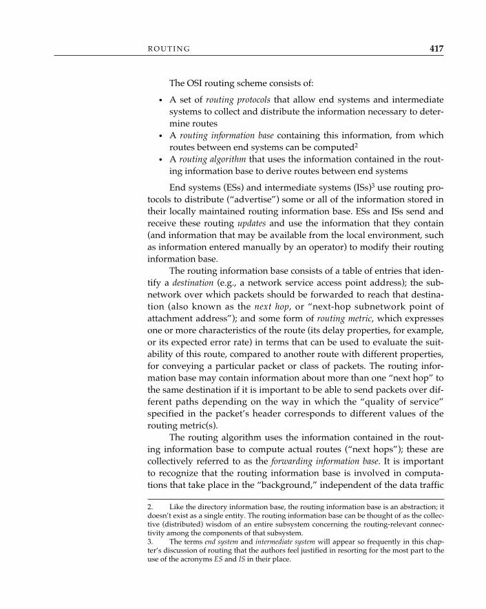
The OSI routing scheme consists of:
• A set of routing protocols that allow end systems and intermediatesystems to collect and distribute the information necessary to deter-mine routes
• A routing information base containing this information, from whichroutes between end systems can be computed2
• A routing algorithm that uses the information contained in the rout-ing information base to derive routes between end systems
End systems (ESs) and intermediate systems (ISs)3 use routing pro-tocols to distribute (“advertise”) some or all of the information stored intheir locally maintained routing information base. ESs and ISs send andreceive these routing updates and use the information that they contain(and information that may be available from the local environment, suchas information entered manually by an operator) to modify their routinginformation base.
The routing information base consists of a table of entries that iden-tify a destination (e.g., a network service access point address); the sub-network over which packets should be forwarded to reach that destina-tion (also known as the next hop, or “next-hop subnetwork point ofattachment address”); and some form of routing metric, which expressesone or more characteristics of the route (its delay properties, for example,or its expected error rate) in terms that can be used to evaluate the suit-ability of this route, compared to another route with different properties,for conveying a particular packet or class of packets. The routing infor-mation base may contain information about more than one “next hop” tothe same destination if it is important to be able to send packets over dif-ferent paths depending on the way in which the “quality of service”specified in the packet’s header corresponds to different values of therouting metric(s).
The routing algorithm uses the information contained in the rout-ing information base to compute actual routes (“next hops”); these arecollectively referred to as the forwarding information base. It is importantto recognize that the routing information base is involved in computa-tions that take place in the “background,” independent of the data traffic
R O U T I N G 417
2. Like the directory information base, the routing information base is an abstraction; itdoesn’t exist as a single entity. The routing information base can be thought of as the collec-tive (distributed) wisdom of an entire subsystem concerning the routing-relevant connec-tivity among the components of that subsystem.3. The terms end system and intermediate system will appear so frequently in this chap-ter’s discussion of routing that the authors feel justified in resorting for the most part to theuse of the acronyms ES and IS in their place.
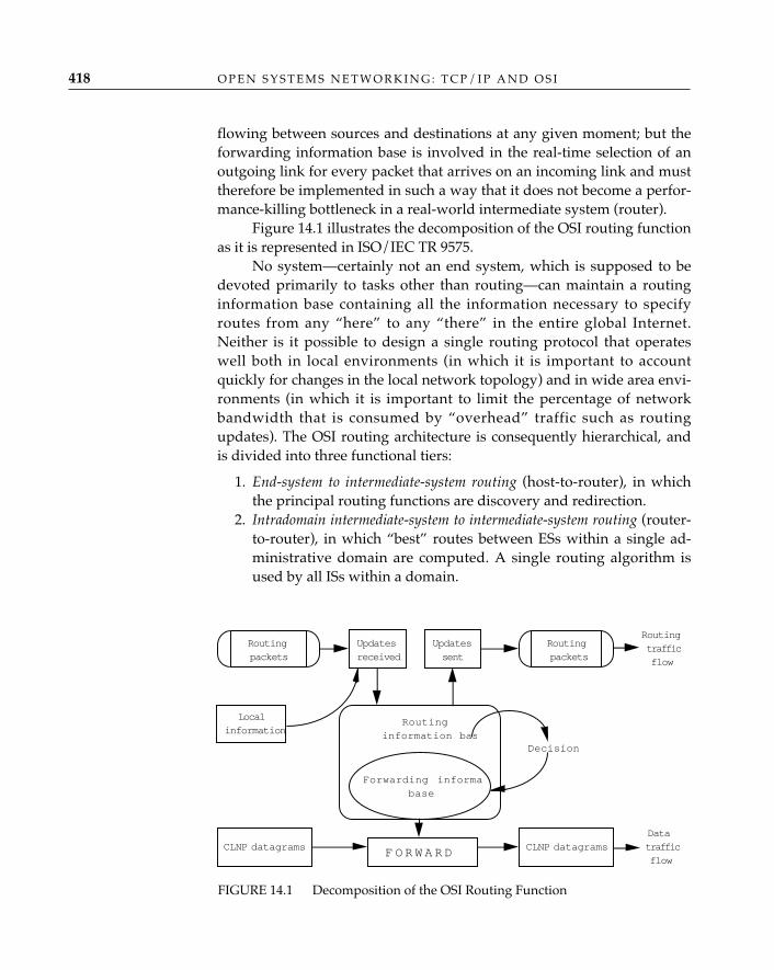
flowing between sources and destinations at any given moment; but theforwarding information base is involved in the real-time selection of anoutgoing link for every packet that arrives on an incoming link and musttherefore be implemented in such a way that it does not become a perfor-mance-killing bottleneck in a real-world intermediate system (router).
Figure 14.1 illustrates the decomposition of the OSI routing functionas it is represented in ISO/IEC TR 9575.
No system—certainly not an end system, which is supposed to bedevoted primarily to tasks other than routing—can maintain a routinginformation base containing all the information necessary to specifyroutes from any “here” to any “there” in the entire global Internet.Neither is it possible to design a single routing protocol that operateswell both in local environments (in which it is important to accountquickly for changes in the local network topology) and in wide area envi-ronments (in which it is important to limit the percentage of networkbandwidth that is consumed by “overhead” traffic such as routingupdates). The OSI routing architecture is consequently hierarchical, andis divided into three functional tiers:
1. End-system to intermediate-system routing (host-to-router), in whichthe principal routing functions are discovery and redirection.
2. Intradomain intermediate-system to intermediate-system routing (router-to-router), in which “best” routes between ESs within a single ad-ministrative domain are computed. A single routing algorithm isused by all ISs within a domain.
O P E N S Y S T E M S N E T W O R K I N G : T C P / I P A N D O S I418
FIGURE 14.1 Decomposition of the OSI Routing Function
Routingpackets
Updatesreceived
Routinginformation bas
Decision
Forwarding informabase
CLNP datagrams
Updatessent
Routingpackets
Localinformation
CLNP datagramsF O R W A R D
Routingtrafficflow
Datatrafficflow
3. Interdomain intermediate-system to intermediate-system routing (router-to-router), in which routes are computed between administrativedomains.
In Figure 14.2, end systems discover and communicate with theintermediate systems to which they are directly connected (by dedicatedor dial-up point-to-point links or by multiaccess local or metropolitanarea networks) in the outermost level of the hierarchy; intermediate sys-tems communicate with other intermediate systems within a single rout-ing domain in the levels of the hierarchy next closest to the center; and inthe center, intermediate systems communicate with other intermediatesystems across routing domain boundaries.
The decomposition illustrated in Figure 14.2 is not arbitrary. Ateach level of the hierarchy, a different set of imperatives governs thechoices that are available for routing algorithms and protocols. In theOSI routing architecture, end systems are not involved in the distribu-tion of routing information and the computation of routes, and hence,the participation of end systems in routing is limited to asking and an-swering the question “Who’s on this subnetwork with me?” (On broad-
R O U T I N G 419
FIGURE 14.2 OSI Routing Architecture
ES–IS
Inter-domain
Intra-domain
ES–IS
Otherdomains
Intra-domain
To other
routers
in this domain
Otherdomains
To other
routers
in this domain
cast subnetworks such as most local area networks, this inquiry typicallybegins with the more or less Cartesian assertion “I broadcast [multicast],therefore I am . . .”)
Within a single routing domain, the hegemony of a single adminis-tration (and a correspondingly consistent set of routing policies) arguesin favor of using a single routing protocol which provides every interme-diate system with complete knowledge of the topology of the routingdomain. (See “Intradomain Routing in OSI,” later in this chapter.)Between routing domains that may be controlled by different (possiblyeven antagonistic) administrations, issues of security (including controlover the extent to which information about the topology of one domain ispropagated to other domains) outweigh most others, and the argumentin favor of distributing complete topology information to all intermediatesystems, so compelling when selecting an intradomain routing protocol,misfires for the very reason that concealing or witholding information isoften as important as distributing it. It is important to recognize that theanalysis that leads to one conclusion in the intradomain context does notnecessarily hold when it is transplanted to the interdomain context.
Fortunately, with respect to routing, it has not been difficult torefute the simplistic argument that if link-state routing is the
best choice for the intradomain level of the routing hierarchy it must be the bestchoice for the interdomain level. Ten years ago, however, a similarly simplisticargument destroyed the opportunity for OSI to standardize one of the best fea-tures of the TCP/IP internetwork architecture—the combination of a connection-less (datagram) internetwork protocol (which could be operated efficiently overany underlying network technology, whether based on datagrams or virtual cir-cuits) with a connection-oriented end-to-end transport protocol (which madeeverything “come out even” at the hosts, or end systems). The OSI position atthat time was that a connection-oriented service at the transport layer “natural-ly” mapped to a connection-oriented service at the network layer, as if this weresomething inherent in the very architecture of a layered model. The OSI commu-nity wasted years dealing with this red herring, which was intended to divertattention from the fact that a large segment of the OSI community believed thatthe service provided by the network layer was an end-to-end transport service.The TCP/IP community, unencumbered by such nonsense, happily expanded tofill the resulting vacuum.
End System to Intermediate System Routing—“ES-IS” routing establishesconnectivity and reachability among ESs and ISs attached to the same(single) subnetwork. Limiting the scope of routing in this manner allows
✧AHA✧
O P E N S Y S T E M S N E T W O R K I N G : T C P / I P A N D O S I420
an ES to play a simple role in the overall routing process and leaves mostof the ES’s resources available to support end-user applications (whichis, presumably, the raison d’être of an ES). ESs are commonly attached tomultiaccess subnetworks, such as IEEE 802 local area networks (LANs) andmetropolitan area networks (MANs), creating topologies that are bothhighly connected and densely populated (with ESs); the protocols andalgorithms that are appropriate for routing in this environment are verydifferent from those that are appropriate for routing in the wide areaenvironments served by intermediate system to intermediate systemrouting.
At this level of routing, the two critical (closely related) concerns arediscovery (who is out there?) and reachability (with whom is it possibleto communicate?). Within a single subnetwork, an ES is one “hop” awayfrom any ES or IS connected to the same subnetwork, so the only infor-mation an ES needs in order to reach either destination ESs on the samesubnetwork or ISs that will forward packets to destination ESs on othersubnetworks is the “hardware interface” or subnetwork point of attachment(SNPA) addresses of the ESs and ISs attached to the subnetwork.
Intradomain Intermediate System to Intermediate System Routing—“IS-IS” routing establishes connectivity among intermediate systems withina single authority, the administrative domain. An administrative domain iscomposed of one or more routing domains. Each routing domain consistsof a set of ISs and ESs; ISs within a routing domain use the same routingprotocol, routing algorithm, and routing metrics.
At this level of routing, the critical concern is the selection andmaintenance of best paths among systems within the administrativedomain. ISs are concerned about route optimization with respect to avariety of metrics and about the trade-off between (1) the cost of distrib-uting and maintaining routing information (which increases as the gran-ularity of the information approaches “a separate route for every source/destination pair for every value of the routing metric[s]”) and (2) the costof actually sending data over a particular route (which increases if theavailable routing information causes data to be sent over a “suboptimal”route).
Interdomain Intermediate System to Intermediate System Routing—In-terdomain IS-IS routing establishes communication among differentadministrative domains, enabling them to control the exchange of infor-mation “across borders.” In most circumstances, it is common to think ofrouting as something that tries to make it “as easy as possible” for twosystems to communicate, regardless of what may lie between them. In-
R O U T I N G 421
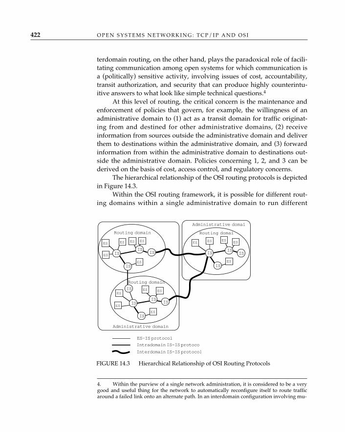
terdomain routing, on the other hand, plays the paradoxical role of facili-tating communication among open systems for which communication isa (politically) sensitive activity, involving issues of cost, accountability,transit authorization, and security that can produce highly counterintu-itive answers to what look like simple technical questions.4
At this level of routing, the critical concern is the maintenance andenforcement of policies that govern, for example, the willingness of anadministrative domain to (1) act as a transit domain for traffic originat-ing from and destined for other administrative domains, (2) receiveinformation from sources outside the administrative domain and deliverthem to destinations within the administrative domain, and (3) forwardinformation from within the administrative domain to destinations out-side the administrative domain. Policies concerning 1, 2, and 3 can bederived on the basis of cost, access control, and regulatory concerns.
The hierarchical relationship of the OSI routing protocols is depictedin Figure 14.3.
Within the OSI routing framework, it is possible for different rout-ing domains within a single administrative domain to run different
O P E N S Y S T E M S N E T W O R K I N G : T C P / I P A N D O S I422
FIGURE 14.3 Hierarchical Relationship of OSI Routing Protocols
4. Within the purview of a single network administration, it is considered to be a verygood and useful thing for the network to automatically reconfigure itself to route trafficaround a failed link onto an alternate path. In an interdomain configuration involving mu-
ES
ISIS
ES
ES ES ES
ES
Routing domain
IS
ES
ISIS
IS
ES
ES ES
ES
IS
ES
IS
IS
ES ES ES
ES
IS
Administrative domain
IS
IS
IS
Administrative domai
ES-IS protocol
Intradomain IS-IS protocol
Interdomain IS-IS protocol
Routing domain
Routing domain
intradomain routing protocols, and it is also possible to operate differentES-IS protocols within different areas of the same routing domain. Atpresent, however, OSI defines only one standard routing protocol foreach of the three levels of the hierarchy.
Through a process of evolution—in which some of the ideas that led tofeatures of the OSI routing architecture originated with TCP/IP, devel-oped into OSI standards, and returned to be adopted by the TCP/IP com-munity—the TCP/IP routing architecture today is almost identical to theOSI architecture. The TCP/IP world began with a single network (whichdidn’t require much in the way of routing), and grew into the “core”-based ARPANET, with individual networks connected to a single back-bone (composed of “core gateways”) as “stubs” (RFC 888; RFC 904).Multiple organizations began offering IP transit services, and for a time, itwas difficult to tell whether the Internet was a “mesh” of backbone net-works or a hierarchy. A three-tier hierarchy was gradually introduced asthe NSFnet5 grew and supplanted the ARPANET: the NSFnet served as anational backbone, and midlevel networks (or “regionals”) provided tran-sit services to and from the IP networks whose directly connected hostsserved as the sources and sinks of Internet traffic.
Today, the TCP/IP routing architecture looks very much like theOSI routing architecture. Hosts use a discovery protocol to obtain theidentification of gateways and other hosts attached to the same network(subnetwork). Gateways within autonomous systems (routing domains)operate an interior gateway protocol (intradomain IS-IS routing protocol),and between autonomous systems, they operate exterior or border gatewayprotocols (interdomain routing protocols). The details are different but theprinciples are the same.
R O U T I N G 423
TCP/IP RoutingArchitecture
tually suspicious network administrations, however, it may be the worst possible thing forthe network to switch traffic to an alternate path “automatically” without first clearing thechange with the legal departments of both parties. This conundrum has led one of theauthors to claim that the only large-scale interdomain routing protocol that is likely to bedeployed in the near future will be implemented as an army of lawyers on bicycles.5. The National Science Foundation network (NSFnet) is the principal wide area back-bone network for the Internet in the United States.
Routing ProtocolsOver the past two decades, there have been more than a dozen routingprotocols in operation in various parts of the Internet: HELLO, RIP (suc-ceeded by RIP II), EGP, GGP, and BGP (which has gone through severalversions, of which the most recent is BGP-4).6 This is largely due to thefact that the Internet has been so successful that it has encountered—more than once!—a fundamental (architectural) limit to the ability of itsprevailing routing technologies to cope with its increased size and extent.OSI benefited enormously from these years of experience with TCP/IPnetworks and can boast today that its routing protocols have been de-signed “from the beginning” to scale into the foreseeable future of bil-lion-node internets. The boast is empty, of course, since the same lessonshave been factored into a new generation of TCP/IP routing protocols; insome cases, in fact, the two communities are close to adopting the samerouting protocol (much to the dismay of protocol-stack isolationists, butmuch to the relief of network operators and users!).
It is impossible to cover each of the TCP/IP routing protocols indetail in this chapter. However, it is instructive to compare a single TCP/IP routing protocol at each level of the routing hierarchy with an equiva-lent OSI protocol. The remainder of the chapter considers each of thethree levels of the hierarchy (which is a common feature of both the OSIand the TCP/IP routing architectures) in turn, examining the OSI proto-col (for which there is just one at each level) in some detail and compar-ing with it the currently recommended TCP/IP counterpart.
In OSI, the discovery paradigm is announcement. An end system uses theend system hello message (ESH) of the ES-IS protocol (ISO/IEC 9542)7 toannounce its presence to intermediate systems (and end systems) con-nected to the same subnetwork. Any end or intermediate system that islistening for ES hello messages gets a copy; intermediate systems willstore the NSAP address and the corresponding subnetwork address pairin routing tables. ESs may do so if they wish, or they may wait to beinformed by intermediate systems when they need such information.
The announcement process is most effective when operated over a
O P E N S Y S T E M S N E T W O R K I N G : T C P / I P A N D O S I424
Reachability andDiscovery inOSI—The ES-ISProtocol
6. RIP: routing information protocol; EGP: exterior gateway protocol; GGP: gateway-to-gateway protocol; BGP: border gateway protocol.7. ISO often carries descriptive naming too far. The full title of the ES-IS standard isEnd System to Intermediate System Routeing Exchange Protocol for Use in Conjunction With theProtocol for Providing the Connectionless-mode Network Service (ISO 8473). No wonder every-one refers to it simply as “ES-IS”!
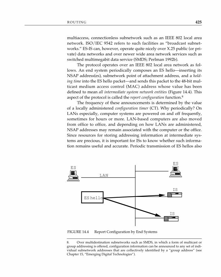
multiaccess, connectionless subnetwork such as an IEEE 802 local areanetwork. ISO/IEC 9542 refers to such facilities as “broadcast subnet-works.” ES-IS can, however, operate quite nicely over X.25 public (or pri-vate) data networks and over newer wide area network services such asswitched multimegabit data service (SMDS; Perlman 1992b).
The protocol operates over an IEEE 802 local area network as fol-lows. An end system periodically composes an ES hello—inserting itsNSAP address(es), subnetwork point of attachment address, and a hold-ing time into the ES hello packet—and sends this packet to the 48-bit mul-ticast medium access control (MAC) address whose value has beendefined to mean all intermediate system network entities (Figure 14.4). Thisaspect of the protocol is called the report configuration function.8
The frequency of these announcements is determined by the valueof a locally administered configuration timer (CT). Why periodically? OnLANs especially, computer systems are powered on and off frequently,sometimes for hours or more. LAN-based computers are also movedfrom office to office, and depending on how LANs are administered,NSAP addresses may remain associated with the computer or the office.Since resources for storing addressing information at intermediate sys-tems are precious, it is important for ISs to know whether such informa-tion remains useful and accurate. Periodic transmission of ES hellos also
R O U T I N G 425
FIGURE 14.4 Report Configuration by End Systems
8. Over multidestination subnetworks such as SMDS, in which a form of multicast orgroup addressing is offered, configuration information can be announced to any set of indi-vidual subnetwork addresses that are collectively identified by a “group address” (seeChapter 15, “Emerging Digital Technologies”).
ESES
IS
ES hello
IST / 2
T / 2
LAN
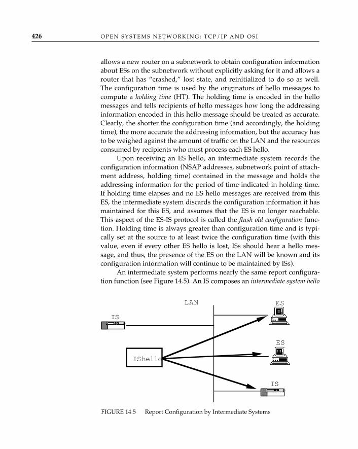
allows a new router on a subnetwork to obtain configuration informationabout ESs on the subnetwork without explicitly asking for it and allows arouter that has “crashed,” lost state, and reinitialized to do so as well.The configuration time is used by the originators of hello messages tocompute a holding time (HT). The holding time is encoded in the hellomessages and tells recipients of hello messages how long the addressinginformation encoded in this hello message should be treated as accurate.Clearly, the shorter the configuration time (and accordingly, the holdingtime), the more accurate the addressing information, but the accuracy hasto be weighed against the amount of traffic on the LAN and the resourcesconsumed by recipients who must process each ES hello.
Upon receiving an ES hello, an intermediate system records theconfiguration information (NSAP addresses, subnetwork point of attach-ment address, holding time) contained in the message and holds theaddressing information for the period of time indicated in holding time.If holding time elapses and no ES hello messages are received from thisES, the intermediate system discards the configuration information it hasmaintained for this ES, and assumes that the ES is no longer reachable.This aspect of the ES-IS protocol is called the flush old configuration func-tion. Holding time is always greater than configuration time and is typi-cally set at the source to at least twice the configuration time (with thisvalue, even if every other ES hello is lost, ISs should hear a hello mes-sage, and thus, the presence of the ES on the LAN will be known and itsconfiguration information will continue to be maintained by ISs).
An intermediate system performs nearly the same report configura-tion function (see Figure 14.5). An IS composes an intermediate system hello
O P E N S Y S T E M S N E T W O R K I N G : T C P / I P A N D O S I426
FIGURE 14.5 Report Configuration by Intermediate Systems
ES
ES
IS
IS hello
IST / 2
T / 2
LAN
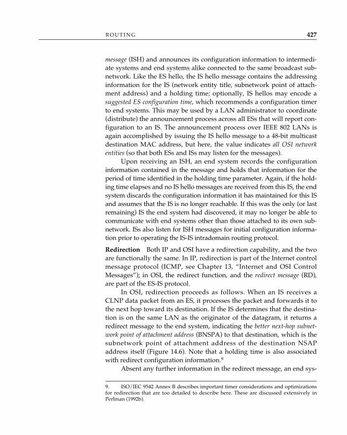
message (ISH) and announces its configuration information to intermedi-ate systems and end systems alike connected to the same broadcast sub-network. Like the ES hello, the IS hello message contains the addressinginformation for the IS (network entity title, subnetwork point of attach-ment address) and a holding time; optionally, IS hellos may encode asuggested ES configuration time, which recommends a configuration timerto end systems. This may be used by a LAN administrator to coordinate(distribute) the announcement process across all ESs that will report con-figuration to an IS. The announcement process over IEEE 802 LANs isagain accomplished by issuing the IS hello message to a 48-bit multicastdestination MAC address, but here, the value indicates all OSI networkentities (so that both ESs and ISs may listen for the messages).
Upon receiving an ISH, an end system records the configurationinformation contained in the message and holds that information for theperiod of time identified in the holding time parameter. Again, if the hold-ing time elapses and no IS hello messages are received from this IS, the endsystem discards the configuration information it has maintained for this ISand assumes that the IS is no longer reachable. If this was the only (or lastremaining) IS the end system had discovered, it may no longer be able tocommunicate with end systems other than those attached to its own sub-network. ISs also listen for ISH messages for initial configuration informa-tion prior to operating the IS-IS intradomain routing protocol.
Redirection—Both IP and OSI have a redirection capability, and the twoare functionally the same. In IP, redirection is part of the Internet controlmessage protocol (ICMP, see Chapter 13, “Internet and OSI ControlMessages”); in OSI, the redirect function, and the redirect message (RD),are part of the ES-IS protocol.
In OSI, redirection proceeds as follows. When an IS receives aCLNP data packet from an ES, it processes the packet and forwards it tothe next hop toward its destination. If the IS determines that the destina-tion is on the same LAN as the originator of the datagram, it returns aredirect message to the end system, indicating the better next-hop subnet-work point of attachment address (BNSPA) to that destination, which is thesubnetwork point of attachment address of the destination NSAPaddress itself (Figure 14.6). Note that a holding time is also associatedwith redirect configuration information.9
Absent any further information in the redirect message, an end sys-
R O U T I N G 427
9. ISO/IEC 9542 Annex B describes important timer considerations and optimizationsfor redirection that are too detailed to describe here. These are discussed extensively inPerlman (1992b).
tem can only conclude that a better path to a given destination NSAP ad-dress exists through an IS identified by the network entity title andBSNPA encoded in the redirect message. For those situations in whichthe identified IS provides a better route to a larger set of destinations—oras ISO/IEC 9542 says, “an equivalence class of NSAP addresses to whichthe same redirection information applies”—an IS can include an addressmask parameter, which indicates just how widely the redirection infor-mation can be applied. The address mask is composed from the destina-tion NSAP address that caused the redirection, with binary 1s identifyinghow much of the NSAP address is the mask. For example, the bits repre-senting the entire initial domain part and the first 16 bits of the domain-specific part of the mask might be set to binary 1s, and the remaining bitsof the domain-specific part set to binary 0s. This signals to the end sys-tem that any time it receives a request to send a data packet to a destina-tion that has the identical initial domain part and the same initial 16 bitsof domain-specific part as this NSAP address, it should forward thepacket to the IS identified in the redirect message.
One can’t help but notice the similarity between the actions ofESs and ISs in this protocol and the actions of the citizens of
Whoville in Dr. Seuss’s Horton Hears a Who, who, attempting to save their
✧AHA✧
O P E N S Y S T E M S N E T W O R K I N G : T C P / I P A N D O S I428
FIGURE 14.6 Redirection of One IS to Another IS
ES 1
IS A
DT PDU
RD PDU
IS B
ES 5
T / 2
DT PDU
T / 2
ES 2
LAN
(1)ES 1 sends
CLNP data packetto ES 5via IS A
(2)IS A forwardspacket to ES5
(3)IS A sends redirecmessage to ES 1containing ES 5's
SNPA
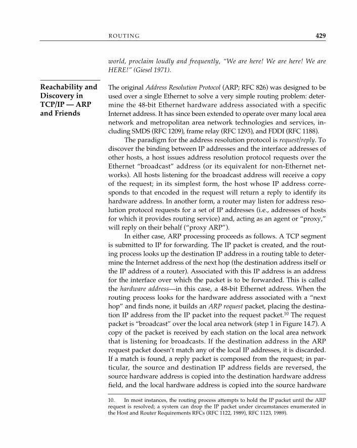
world, proclaim loudly and frequently, “We are here! We are here! We areHERE!” (Giesel 1971).
The original Address Resolution Protocol (ARP; RFC 826) was designed to beused over a single Ethernet to solve a very simple routing problem: deter-mine the 48-bit Ethernet hardware address associated with a specificInternet address. It has since been extended to operate over many local areanetwork and metropolitan area network technologies and services, in-cluding SMDS (RFC 1209), frame relay (RFC 1293), and FDDI (RFC 1188).
The paradigm for the address resolution protocol is request/reply. Todiscover the binding between IP addresses and the interface addresses ofother hosts, a host issues address resolution protocol requests over theEthernet “broadcast” address (or its equivalent for non-Ethernet net-works). All hosts listening for the broadcast address will receive a copyof the request; in its simplest form, the host whose IP address corre-sponds to that encoded in the request will return a reply to identify itshardware address. In another form, a router may listen for address reso-lution protocol requests for a set of IP addresses (i.e., addresses of hostsfor which it provides routing service) and, acting as an agent or “proxy,”will reply on their behalf (“proxy ARP”).
In either case, ARP processing proceeds as follows. A TCP segmentis submitted to IP for forwarding. The IP packet is created, and the rout-ing process looks up the destination IP address in a routing table to deter-mine the Internet address of the next hop (the destination address itself orthe IP address of a router). Associated with this IP address is an addressfor the interface over which the packet is to be forwarded. This is calledthe hardware address—in this case, a 48-bit Ethernet address. When therouting process looks for the hardware address associated with a “nexthop” and finds none, it builds an ARP request packet, placing the destina-tion IP address from the IP packet into the request packet.10 The requestpacket is “broadcast” over the local area network (step 1 in Figure 14.7). Acopy of the packet is received by each station on the local area networkthat is listening for broadcasts. If the destination address in the ARPrequest packet doesn’t match any of the local IP addresses, it is discarded.If a match is found, a reply packet is composed from the request; in par-ticular, the source and destination IP address fields are reversed, thesource hardware address is copied into the destination hardware addressfield, and the local hardware address is copied into the source hardware
R O U T I N G 429
Reachability andDiscovery inTCP/IP — ARPand Friends
10. In most instances, the routing process attempts to hold the IP packet until the ARPrequest is resolved; a system can drop the IP packet under circumstances enumerated inthe Host and Router Requirements RFCs (RFC 1122, 1989), RFC 1123, 1989).
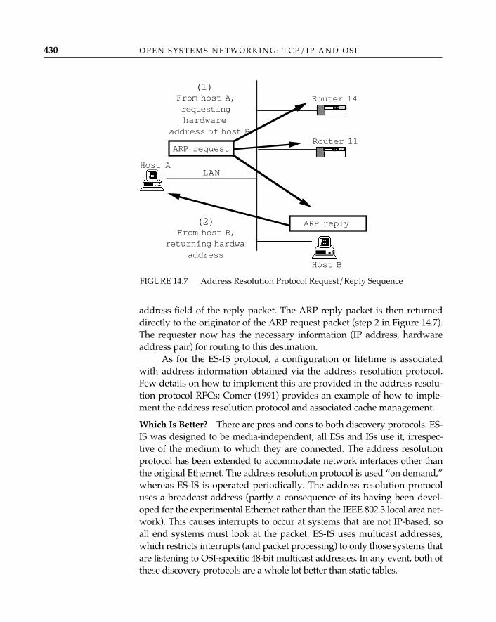
address field of the reply packet. The ARP reply packet is then returneddirectly to the originator of the ARP request packet (step 2 in Figure 14.7).The requester now has the necessary information (IP address, hardwareaddress pair) for routing to this destination.
As for the ES-IS protocol, a configuration or lifetime is associatedwith address information obtained via the address resolution protocol.Few details on how to implement this are provided in the address resolu-tion protocol RFCs; Comer (1991) provides an example of how to imple-ment the address resolution protocol and associated cache management.
Which Is Better?—There are pros and cons to both discovery protocols. ES-IS was designed to be media-independent; all ESs and ISs use it, irrespec-tive of the medium to which they are connected. The address resolutionprotocol has been extended to accommodate network interfaces other thanthe original Ethernet. The address resolution protocol is used “on demand,”whereas ES-IS is operated periodically. The address resolution protocoluses a broadcast address (partly a consequence of its having been devel-oped for the experimental Ethernet rather than the IEEE 802.3 local area net-work). This causes interrupts to occur at systems that are not IP-based, soall end systems must look at the packet. ES-IS uses multicast addresses,which restricts interrupts (and packet processing) to only those systems thatare listening to OSI-specific 48-bit multicast addresses. In any event, both ofthese discovery protocols are a whole lot better than static tables.
O P E N S Y S T E M S N E T W O R K I N G : T C P / I P A N D O S I430
FIGURE 14.7 Address Resolution Protocol Request/Reply Sequence
Host A
Router 11ARP request
Router 14From host A,requestinghardware
address of host B
T / 2
T / 2
LAN
ARP replyFrom host B,
returning hardwaraddress
Host B
(1)
(2)
The OSI intradomain IS-IS routing protocol (ISO/IEC 10589) operateswithin a routing domain to provide every IS with complete knowledgeof the topology of the routing domain. Generally speaking, within a sin-gle routing domain, small convergence time and simplicity of operationare more important than trust and fire walls. Thus, the main design goalsof IS-IS are to
• Accommodate large routing domains: IS-IS is designed to handle100,000 NSAP addresses and 10,000 ISs in a single routing domain.
• Converge quickly: When a change in topology in the routing domainoccurs, IS-IS converges to correct routes quickly and without oscil-lation.
• Provide operational “simplicity”: In the OSI routing architecture, therole of ESs in routing is extremely simple, and with IS-IS, the con-figuration and parameter tuning of ISs is also relatively simple. IS-IS is relatively simple to maintain as well.
• Support multiple subnetwork types: IS-IS is designed to operate overlocal area networks, metropolitan area networks, point-to-pointlinks, and X.25 networks. These subnetworks have widely differingdelay, bandwidth, and operational characteristics (e.g., some offerconnections, and some run datagrams), yet IS-IS is immune to thedifferences.
To accommodate large routing domains, IS-IS is organized as atwo-level hierarchy. The subdomains that comprise level 1 of the hierar-chy are called areas, and level-1 ISs within an area maintain routes only todestinations within their area. Routes to destination areas within thesame routing domain (and routes to areas in other routing domains ab-sent any policy restrictions—e.g., shortest paths to destination routingdomains) are maintained at the second level of the hierarchy, by level-2ISs (note that ISs designated as “level-2 ISs” maintain both level-1 andlevel-2 routes).
To converge quickly on the best (shortest) routes, IS-IS uses both alink-state routing algorithm based on the “new ARPANET” algorithmdeveloped by McQuillan, Richter, and Rosen (1980), and the fault-toler-ant broadcast mechanism developed by Radia Perlman (1983). IS-IS com-putes routes using the Dijkstra shortest path first (SPF) algorithm. Link-state routing avoids the “count-to-infinity,” oscillatory behavior exhibit-ed by many distance-vector algorithms such as the routing informationprotocol (RIP; RFC 1058, 1988). In a distance-vector routing environment,each router passes to its neighbors information about routes to destina-tions that the router has computed based on information it has received
R O U T I N G 431
IntradomainRouting in OSI
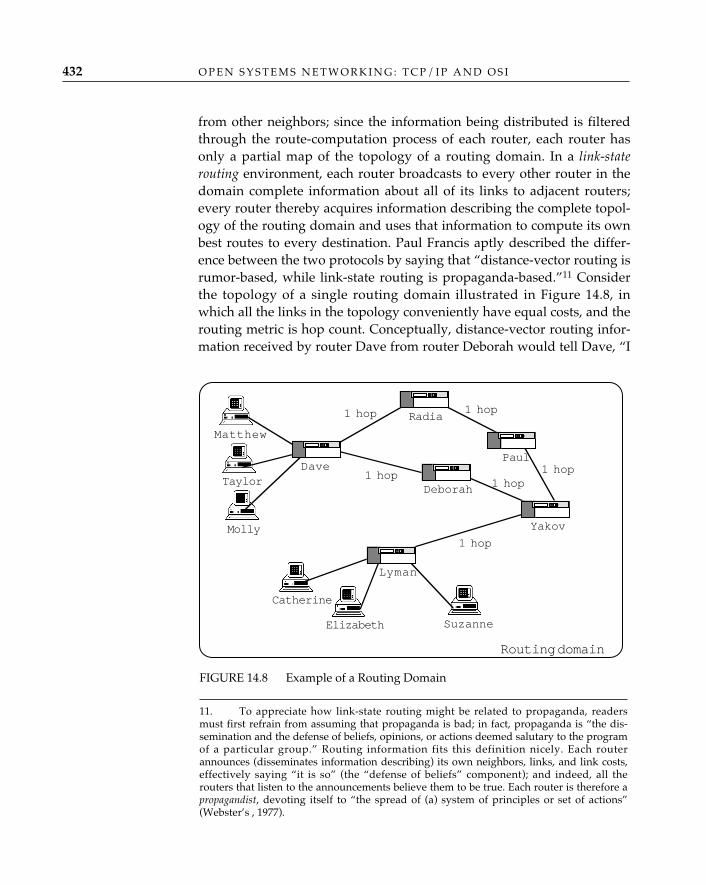
from other neighbors; since the information being distributed is filteredthrough the route-computation process of each router, each router hasonly a partial map of the topology of a routing domain. In a link-staterouting environment, each router broadcasts to every other router in thedomain complete information about all of its links to adjacent routers;every router thereby acquires information describing the complete topol-ogy of the routing domain and uses that information to compute its ownbest routes to every destination. Paul Francis aptly described the differ-ence between the two protocols by saying that “distance-vector routing isrumor-based, while link-state routing is propaganda-based.”11 Considerthe topology of a single routing domain illustrated in Figure 14.8, inwhich all the links in the topology conveniently have equal costs, and therouting metric is hop count. Conceptually, distance-vector routing infor-mation received by router Dave from router Deborah would tell Dave, “I
O P E N S Y S T E M S N E T W O R K I N G : T C P / I P A N D O S I432
11. To appreciate how link-state routing might be related to propaganda, readersmust first refrain from assuming that propaganda is bad; in fact, propaganda is “the dis-semination and the defense of beliefs, opinions, or actions deemed salutary to the programof a particular group.” Routing information fits this definition nicely. Each routerannounces (disseminates information describing) its own neighbors, links, and link costs,effectively saying “it is so” (the “defense of beliefs” component); and indeed, all therouters that listen to the announcements believe them to be true. Each router is therefore apropagandist, devoting itself to “the spread of (a) system of principles or set of actions”(Webster’s , 1977).
FIGURE 14.8 Example of a Routing Domain
Dave
Elizabeth
Catherine
Suzanne
Molly
Taylor
Matthew
Yakov
Deborah
Radia
Paul
1 hop1 hop
1 hop
1 hop 1 hop
1 hop
Routing domain
Lyman
(Deborah) hear that I can get to Lyman, so you can get to Lyman throughme, but it will cost you 2 hops”; the routing packet would be a bit moresuccinct, saying perhaps in this case that Deborah has a 2-hop route toLyman. Dave would add the cost of the link he shares with Deborah (1hop) and conclude that the cost of the path through Deborah to Lyman is3 hops. Dave, hearing from Radia that she hears she can reach Lyman in3 hops, would add the cost of the link he shares with Radia and concludethat the best path to Lyman is through Deborah (3 hops) rather thanthrough Radia (4 hops).
Link-state routing information is distributed quite differently, andpaints a very different conceptual picture of the topology. Deborahwould announce (“advertise”) a list of neighboring routers (Dave,Yakov) over each of her links; Yakov would announce his list (Deborah,Paul, Lyman), Radia her list (Dave, Paul), Paul his list (Radia, Yakov),and Lyman his list (Suzanne, Catherine, and Elizabeth—perhaps collec-tively referred to as “the Chapins”, and Yakov). Dutifully, Dave wouldannounce his list as well (Molly, Matthew, and Taylor—the “Piscitel-los”—Deborah, and Radia).12
This information is flooded through the entire routing domain;everyone hears about everyone else’s links, neighbors, and link costs.Dave waits until it’s quiet, then deduces from the collection of announce-ments that “I can get to Deborah (1 hop); Deborah can get to Yakov (1hop); Yakov can get to Lyman (1 hop); therefore I can get to Lyman overthe link to Deborah in 3 hops!” (Having the entire set of announcements,Dave also deduces that he can get to Lyman over the link to Radia in 4hops, and elects to use the path through Deborah; of course, since Radiawas kind enough to offer Dave an alternative path, he keeps this in theback of his mind—just in case Deborah goes away, or becomes verybusy).
The selection of a standard IS-IS protocol for OSI began in theUnited States in 1987 and is remembered as the “late, great,
OSI routing debate.” Two routing protocols were introduced as candidates—one from Digital Equipment Corporation and one from Burroughs (Unisys).Both protocols scaled well and offered hierarchical, multiple–quality of servicerouting with partition repair. The principal difference was that the DEC proto-col was a link-state or “new ARPANET” protocol, and the Burroughs protocol
✧AHA✧
R O U T I N G 433
12. Distance-vector and link-state routing share the notion of neighbor greetingsexchange, in which each router identifies itself to its neighbors when a link comes up or itsstatus changes.
was a distance-vector or “old ARPANET” protocol.The most damning fault of distance-vector routing is that it converges too
slowly following topology changes. The Burroughs protocol, based on the Bur-roughs Integrated Adaptive Routing Algorithm System (BIAS) used in theBurroughs Network Architecture (BNA) (Piscitello and Gruchevsky 1987;Rosenberg, Piscitello, and Gruchevsky 1987), incorporated many improvements(Jaffe and Moss 1982; Kamoun and Kleinrock 1977; Tajibnapis 1977) to theoriginal Bellman-Ford algorithm that dramatically reduced the seriousness of theproblem, but it could not converge as quickly as the DEC link state protocol, andthis difference proved to be the deciding factor.
A generic description of the IS-IS protocol follows. Initially, routersbegin by learning about other routers to which they share direct connec-tivity; i.e., a router X learns first about those routers that are attached tothe same subnetworks as X, often by using the IS hellos described earlier.This process is called neighbor greeting, or neighbor initialization. Eachrouter then constructs a link-state packet (LSP), which contains a list of thenames of its neighbors and its cost13 to reach each of those neighbors.Routers then distribute these link-state packets to all the other routers.When all the link-state packets have been propagated to all the routers,each router will have received a complete map of the network topologyin the form of link-state packets; each router uses these link-state packetsto compute routes to every “destination” in the network using Dijkstra’sshortest path first algorithm.14
All of the OSI NSAP address formats (see Chapter 13) can be usedwith the IS-IS routing protocol. For the purpose of computing routes, anNSAP address is always interpreted by IS-IS as having three fields: anarea address, a system identifier, and an NSAP selector. The area addressidentifies an area within a routing domain; the system identifier unam-biguously identifies a system or “host” within that area; and the NSAPselector identifies an entity within the system (a transport entity in an ESor a network entity in an IS; the NSAP selector is the OSI functional equi-valent of the protocol identifier in IP). The relationship between the gen-
O P E N S Y S T E M S N E T W O R K I N G : T C P / I P A N D O S I434
13. IS-IS uses non–traffic-based metrics to compute route costs. The metrics are insen-sitive to traffic, so IS-IS is able to avoid unnecessary recomputation of routes when trafficpatterns on links oscillate. The default metric is capacity (a measure roughly equal tobits per second); however, IS-IS computes routes based on transit delay, cost (incrementalexpense, such as a charge per packet), and error (a measure of the probability of undetect-ed errors on a circuit) so that CLNP datagrams originated with the QOS maintenance bitsset (see Chapter 13) can be forwarded as requested by the originator.14. Details of link-state packet distribution schemes and computation of Dijkstra’s SPFalgorithm as applied in IS-IS routing are described in Perlman (1992a).
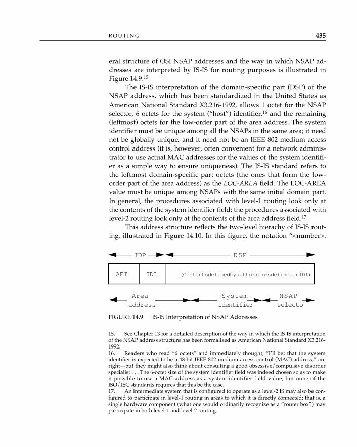
eral structure of OSI NSAP addresses and the way in which NSAP ad-dresses are interpreted by IS-IS for routing purposes is illustrated inFigure 14.9.15
The IS-IS interpretation of the domain-specific part (DSP) of theNSAP address, which has been standardized in the United States asAmerican National Standard X3.216-1992, allows 1 octet for the NSAPselector, 6 octets for the system (“host”) identifier,16 and the remaining(leftmost) octets for the low-order part of the area address. The systemidentifier must be unique among all the NSAPs in the same area; it neednot be globally unique, and it need not be an IEEE 802 medium accesscontrol address (it is, however, often convenient for a network adminis-trator to use actual MAC addresses for the values of the system identifi-er as a simple way to ensure uniqueness). The IS-IS standard refers tothe leftmost domain-specific part octets (the ones that form the low-order part of the area address) as the LOC-AREA field. The LOC-AREAvalue must be unique among NSAPs with the same initial domain part.In general, the procedures associated with level-1 routing look only atthe contents of the system identifier field; the procedures associated withlevel-2 routing look only at the contents of the area address field.17
This address structure reflects the two-level hierachy of IS-IS rout-ing, illustrated in Figure 14.10. In this figure, the notation “<number>.
R O U T I N G 435
15. See Chapter 13 for a detailed description of the way in which the IS-IS interpretationof the NSAP address structure has been formalized as American National Standard X3.216-1992.16. Readers who read “6 octets” and immediately thought, “I’ll bet that the systemidentifier is expected to be a 48-bit IEEE 802 medium access control (MAC) address,” areright—but they might also think about consulting a good obsessive/compulsive disorderspecialist . . . The 6-octet size of the system identifier field was indeed chosen so as to makeit possible to use a MAC address as a system identifier field value, but none of theISO/IEC standards requires that this be the case.17. An intermediate system that is configured to operate as a level-2 IS may also be con-figured to participate in level-1 routing in areas to which it is directly connected; that is, asingle hardware component (what one would ordinarily recognize as a “router box”) mayparticipate in both level-1 and level-2 routing.
FIGURE 14.9 IS-IS Interpretation of NSAP Addresses
AFI IDI (Contents defined by authorities defined in IDI)
IDP DSP
Areaaddress
Systemidentifier
NSAPselecto
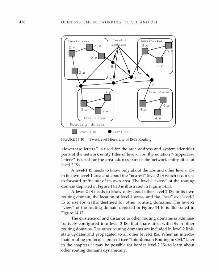
<lowercase letter>” is used for the area address and system identifierparts of the network entity titles of level-1 ISs; the notation “<uppercaseletter>” is used for the area address part of the network entity titles oflevel-2 ISs.
A level-1 IS needs to know only about the ESs and other level-1 ISsin its own level-1 area and about the “nearest” level-2 IS which it can useto forward traffic out of its own area. The level-1 “view” of the routingdomain depicted in Figure 14.10 is illustrated in Figure 14.11.
A level-2 IS needs to know only about other level-2 ISs in its ownrouting domain, the location of level-1 areas, and the “best” exit level-2IS to use for traffic destined for other routing domains. The level-2“view” of the routing domain depicted in Figure 14.10 is illustrated inFigure 14.12.
The existence of and distance to other routing domains is adminis-tratively configured into level-2 ISs that share links with ISs in otherrouting domains. The other routing domains are included in level-2 link-state updates and propagated to all other level-2 ISs. When an interdo-main routing protocol is present (see “Interdomain Routing in OSI,” laterin the chapter), it may be possible for border level-2 ISs to learn aboutother routing domains dynamically.
O P E N S Y S T E M S N E T W O R K I N G : T C P / I P A N D O S I436
FIGURE 14.10 Two-Level Hierarchy of IS-IS Routing
Level-1 IS
2.y
2.x
2.w
2.z
5.y
5.z
5.x
3.x
3.y
3.z4.x
4.z
4.yLevel-1 area
Level-1 area
Level-1 areaLevel-1 area
E
D
B
C
A
Routing domain
Level-2backbone
Level-2 IS
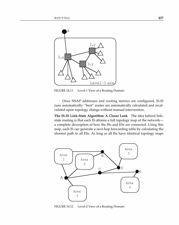
Once NSAP addresses and routing metrics are configured, IS-ISruns automatically: “best” routes are automatically calculated and recal-culated upon topology change without manual intervention.
The IS-IS Link-State Algorithm: A Closer Look—The idea behind link-state routing is that each IS obtains a full topology map of the network—a complete description of how the ISs and ESs are connected. Using thismap, each IS can generate a next-hop forwarding table by calculating theshortest path to all ESs. As long as all ISs have identical topology maps
R O U T I N G 437
FIGURE 14.12 Level-2 View of a Routing Domain
ED
B
C
A
Area1 Area
2
Area5
Area4
Area3
FIGURE 14.11 Level-1 View of a Routing Domain
3.x
3.y
3.z
Level-1 area
A
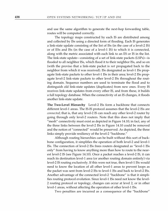
and use the same algorithm to generate the next-hop forwarding table,routes will be computed correctly.
The topology maps constructed by each IS are distributed amongand collected by ISs using a directed form of flooding. Each IS generatesa link-state update consisting of the list of ISs (in the case of a level-2 IS)or of ESs and ISs (in the case of a level-1 IS) to which it is connected,along with the metric associated with each link to an ES or IS in the list.The link-state update—consisting of a set of link-state packets (LSPs)—isflooded to all neighbor ISs, which flood it to their neighbor ISs, and so on(with the proviso that a link-state packet is not propagated back to theneighbor from which it was received). ISs designated as level-1 ISs prop-agate link-state packets to other level-1 ISs in their area; level-2 ISs prop-agate level-2 link-state packets to other level-2 ISs throughout the rout-ing domain. Sequence numbers are used to terminate the flood and todistinguish old link-state updates (duplicates) from new ones. Every ISreceives link-state updates from every other IS, and from these, it buildsa full topology database. When the connectivity of an IS changes, it floodsanother link-state update.
The Two-Level Hierarchy—Level-2 ISs form a backbone that connectsdifferent level-1 areas. The IS-IS protocol assumes that the level-2 ISs areconnected; that is, that any level-2 IS can reach any other level-2 router bygoing through only level-2 routers. Note that this does not imply that“mesh” connectivity must exist as depicted in Figure 14.10; in fact, any ofthe three links between the level-2 ISs in Figure 14.10 could be removedand the notion of “connected” would be preserved. As depicted, the threelinks simply provide resiliency of the level-2 “backbone.”
Although routing hierarchies can be built without this sort of back-bone configuration, it simplifies the operation of both level-2 and level-1ISs. The connection of level-2 ISs frees routers designated as “level-1 ISsonly” from having to know anything more than how to route to the near-est level-2 IS (see Figure 14.10). Once a packet reaches a level-2 IS, it canreach its destination level-1 area (or another routing domain entirely) vialevel-2 IS routing exclusively. If this were not true, then level-1 ISs wouldneed to know the location of all other level-1 areas to prevent loops asthe packet was sent from level-2 ISs to level-1 ISs and back to level-2 ISs.Another advantage of the connected level-2 “backbone” is that it simpli-fies routing protocol evolution. Since level-1 ISs need not know the level-2 routing protocol or topology, changes can occur at level 2, or in otherlevel-1 areas, without affecting the operation of other level-1 ISs.
Two penalties are incurred as a consequence of the “backbone”
O P E N S Y S T E M S N E T W O R K I N G : T C P / I P A N D O S I438
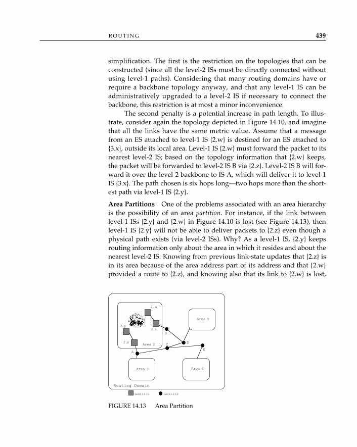
simplification. The first is the restriction on the topologies that can beconstructed (since all the level-2 ISs must be directly connected withoutusing level-1 paths). Considering that many routing domains have orrequire a backbone topology anyway, and that any level-1 IS can beadministratively upgraded to a level-2 IS if necessary to connect thebackbone, this restriction is at most a minor inconvenience.
The second penalty is a potential increase in path length. To illus-trate, consider again the topology depicted in Figure 14.10, and imaginethat all the links have the same metric value. Assume that a messagefrom an ES attached to level-1 IS {2.w} is destined for an ES attached to{3.x}, outside its local area. Level-1 IS {2.w} must forward the packet to itsnearest level-2 IS; based on the topology information that {2.w} keeps,the packet will be forwarded to level-2 IS B via {2.z}. Level-2 IS B will for-ward it over the level-2 backbone to IS A, which will deliver it to level-1IS {3.x}. The path chosen is six hops long—two hops more than the short-est path via level-1 IS {2.y}.
Area Partitions—One of the problems associated with an area hierarchyis the possibility of an area partition. For instance, if the link betweenlevel-1 ISs {2.y} and {2.w} in Figure 14.10 is lost (see Figure 14.13), thenlevel-1 IS {2.y} will not be able to deliver packets to {2.z} even though aphysical path exists (via level-2 ISs). Why? As a level-1 IS, {2.y} keepsrouting information only about the area in which it resides and about thenearest level-2 IS. Knowing from previous link-state updates that {2.z} isin its area because of the area address part of its address and that {2.w}provided a route to {2.z}, and knowing also that its link to {2.w} is lost,
R O U T I N G 439
FIGURE 14.13 Area Partition
Level 1 IS
2.y
2.x
2.w
2.z
Area 2
E
D
B
C
A
Routing Domain
Level 2 IS
Area 5
Area 4Area 3
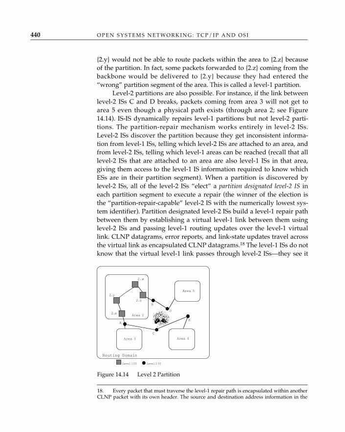
{2.y} would not be able to route packets within the area to {2.z} becauseof the partition. In fact, some packets forwarded to {2.z} coming from thebackbone would be delivered to {2.y} because they had entered the“wrong” partition segment of the area. This is called a level-1 partition.
Level-2 partitions are also possible. For instance, if the link betweenlevel-2 ISs C and D breaks, packets coming from area 3 will not get toarea 5 even though a physical path exists (through area 2; see Figure14.14). IS-IS dynamically repairs level-1 partitions but not level-2 parti-tions. The partition-repair mechanism works entirely in level-2 ISs.Level-2 ISs discover the partition because they get inconsistent informa-tion from level-1 ISs, telling which level-2 ISs are attached to an area, andfrom level-2 ISs, telling which level-1 areas can be reached (recall that alllevel-2 ISs that are attached to an area are also level-1 ISs in that area,giving them access to the level-1 IS information required to know whichESs are in their partition segment). When a partition is discovered bylevel-2 ISs, all of the level-2 ISs “elect” a partition designated level-2 IS ineach partition segment to execute a repair (the winner of the election isthe “partition-repair-capable” level-2 IS with the numerically lowest sys-tem identifier). Partition designated level-2 ISs build a level-1 repair pathbetween them by establishing a virtual level-1 link between them usinglevel-2 ISs and passing level-1 routing updates over the level-1 virtuallink. CLNP datagrams, error reports, and link-state updates travel acrossthe virtual link as encapsulated CLNP datagrams.18 The level-1 ISs do notknow that the virtual level-1 link passes through level-2 ISs—they see it
O P E N S Y S T E M S N E T W O R K I N G : T C P / I P A N D O S I440
Level 1 IS
2.y
2.x
2.w
2.z
Area 2
E
D
B
C
A
Routing Domain
Level 2 IS
Area 5
Area 4Area 3
Figure 14.14 Level 2 Partition
18. Every packet that must traverse the level-1 repair path is encapsulated within anotherCLNP packet with its own header. The source and destination address information in the
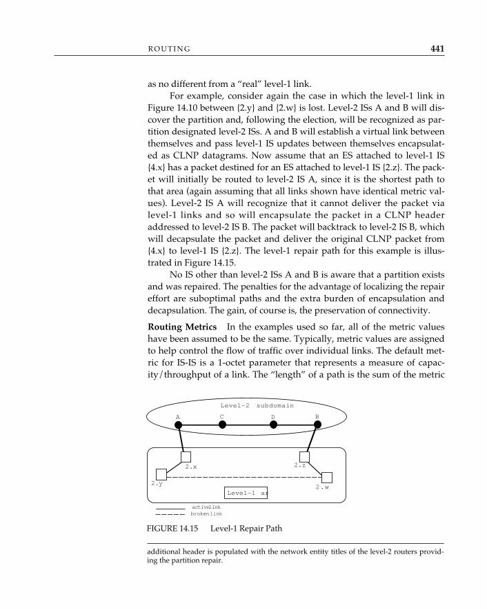
as no different from a “real” level-1 link.For example, consider again the case in which the level-1 link in
Figure 14.10 between {2.y} and {2.w} is lost. Level-2 ISs A and B will dis-cover the partition and, following the election, will be recognized as par-tition designated level-2 ISs. A and B will establish a virtual link betweenthemselves and pass level-1 IS updates between themselves encapsulat-ed as CLNP datagrams. Now assume that an ES attached to level-1 IS{4.x} has a packet destined for an ES attached to level-1 IS {2.z}. The pack-et will initially be routed to level-2 IS A, since it is the shortest path tothat area (again assuming that all links shown have identical metric val-ues). Level-2 IS A will recognize that it cannot deliver the packet vialevel-1 links and so will encapsulate the packet in a CLNP headeraddressed to level-2 IS B. The packet will backtrack to level-2 IS B, whichwill decapsulate the packet and deliver the original CLNP packet from{4.x} to level-1 IS {2.z}. The level-1 repair path for this example is illus-trated in Figure 14.15.
No IS other than level-2 ISs A and B is aware that a partition existsand was repaired. The penalties for the advantage of localizing the repaireffort are suboptimal paths and the extra burden of encapsulation anddecapsulation. The gain, of course is, the preservation of connectivity.
Routing Metrics In the examples used so far, all of the metric valueshave been assumed to be the same. Typically, metric values are assignedto help control the flow of traffic over individual links. The default met-ric for IS-IS is a 1-octet parameter that represents a measure of capac-ity/throughput of a link. The “length” of a path is the sum of the metric
R O U T I N G 441
FIGURE 14.15 Level-1 Repair Path
A B
2.y
2.x 2.z
2.w
C D
Level-2 subdomain
Level-1 are
active linkbroken link
additional header is populated with the network entity titles of the level-2 routers provid-ing the partition repair.
values for the links on that path. One octet was chosen because it givesadequate granularity and allows for an efficient implementation of theshortest-path-first route calculation—i.e., it allows ISs to generate the for-warding table from the topology map efficiently and quickly.19
IS-IS optionally computes routes based on metrics for transit delay,cost, and error rate, so that CLNP datagrams originated with the qualityof service maintenance bits set can be forwarded as requested by the orig-inator over appropriate routes. ISs that compute routes based on optionalmetrics report these metric values for links in link-state packets (in whicha separate octet is identified for each optional metric). ISs compute quali-ty of service routes by using only link-state packets that contain valuesfor a given metric; for example, to compute a “cost” route, an IS will runthe shortest-path-first algorithm using only those link-state updates thatindicate a value for the cost metric and only if the IS itself has a link witha cost metric associated with it.
Partial Routing Updates—Since the purpose of a routing protocol is toassist in directing traffic, and not to consume resources that might other-wise be employed to forward user data, it is always desirable to keeprouting updates small while still keeping track of which neighbors arereachable and which are not. IS-IS routing updates originally conveyedwhich neighbors were reachable by listing them and which neighborswere not reachable by not listing them; if a neighbor was listed in a pre-vious routing update but was not in the latest routing update, that neigh-bor was assumed to be unreachable. As a result, all existing neighborswere listed in all routing updates.
The more neighbors a router had, the larger its routing updates.Large updates had to be fragmented and reassembled by CLNP, whichslowed down the entire update process (since the fragments had to bereassembled at each hop during flooding). IS-IS now uses partial updatesto circumvent this problem.
With partial updates, the otherwise complete routing update is splitinto multiple updates, and each update indicates the numerical range ofneighbors that are covered by the update. This way, the semantics ofexplicitly listing reachable neighbors and implicitly listing unreachableneighbors is preserved. If a partial routing update does not list a neigh-bor that is in the range covered by the update, then it is assumed that theneighbor is unreachable. The various partial updates each maintain their
O P E N S Y S T E M S N E T W O R K I N G : T C P / I P A N D O S I442
19. An implementation of the shortest path first algorithm used by IS-IS is likely toassume that an IS maintains an intermediate table of entries, ordered by distance; by limit-ing distance values to 1 octet, this intermediate table is bounded to a reasonable size.
own sequence numbers. If the status of a neighbor changes, only the par-tial update covering that neighbor must be sent.
Pseudonodes—IS-IS defines another method of limiting the size of rout-ing updates for those configurations in which many ISs populate abroadcast subnetwork (such as a local area network). On these subnet-works, and using the general case principles, each IS is a neighbor of allthe other ISs attached to the same subnetwork. If each of the N ISs on abroadcast subnetwork were to send full routing updates, then N ISswould each send a routing update describing N – 1 neighbors, burdeningthe subnetwork with the exchange of order N(N–1) routing information.To prevent this, one IS on the subnetwork is elected as the pseudonode orLAN desigated router (see Perlman, 1992a). The pseudonode advertisesall the other ISs (including itself) as its neighbors, but all the other ISsadvertise only the pseudonode as their neighbor. With the pseudonode, alogical star configuration with N links is formed rather than the originalfully connected “mesh” configuration with N(N–1) links. To maintain thecorrect metric values, the metric value from the pseudonode to the (real)ISs is 0.
Operation over X.25 Subnetworks—When operating over an ISO/IEC8208 (X.25) subnetwork, IS-IS distinguishes virtual circuits established byadministrative procedure (static) from virtual circuits established becauseof the receipt of a CLNP packet (dynamically allocated, as described inthe CLNP standard). Among the dynamically allocated circuits, IS-IS alsodistinguishes those for which the NSAP addresses reachable via theneighbor are learned from routing updates from those for which theNSAP addresses reachable via the neighbor are locally administered. Thelatter case allows the use of X.25 subnetworks without requiring that thevirtual circuits be left open solely for the purpose of exchanging routingupdates. Depending on the tariffs associated with a particular X.25 net-work service, call duration may be an expensive proposition, and thisoptimization leaves such links open only when they are needed.
“Integrated IS-IS”—The OSI standard for IS-IS (ISO/IEC 10589: 1992)deals only with the provision of routing information to support the for-warding of CLNP packets. Internet RFC 1195 augments the base stan-dard by describing how IS-IS can be used to route both CLNP and IPdatagrams. RFC 1195 specifies how ISs distribute information about theTCP/IP destinations they can reach in addition to the OSI destinationsthey can reach, simply by adding more information to the IS-IS link-statepackets. The mechanism extends naturally to environments that includeother protocol stacks as well; for example, the techniques described in
R O U T I N G 443
RFC 1195 could be used to build routes to XNS/IPX20 destinations byadding IPX-specific information to link-state packets.
The term used to describe the operation of a single intradomainrouting protocol to support the forwarding of traffic associated with mul-tiple protocol stacks is integrated routing. The alternative to integratedrouting, of course, is to run a separate intradomain routing protocol foreach protocol stack (OSI, TCP/IP, XNS/IPX, etc.). Advocates of integrat-ed IS-IS cite the advantages of fewer protocols to operate, fewer re-sources devoted to the routing process, and simpler management.Advocates of the alternative (which is called “ships in the night,” or“S.I.N.,” by members of the Internet community) cite the advantages ofintradomain protocols that are custom-tailored to their correspondingprotocol stacks, noninterference of one protocol stack (and its routingconcerns) with others, and the ability to configure ISs with only thoseintradomain routing functions that are needed for the stack(s) that will besupported.
A variety of different intradomain routing protocols are operated in theInternet today. The most commonly used is the routing information proto-col (RIP; RFC 1058). RIP is the routing protocol “we love to hate”; itsmain problem is that today’s Internet is far too big and diverse for it tohandle. The routing information protocol operates as an application overthe user datagram protocol (UDP), computes routes using a distance-vec-tor algorithm, and uses a hop-count metric that reflects distance but notlink speed, efficiency, or congestion. The routing information protocol isvulnerable (as are all distance-vector routing protocols) to loops; to avoidthem, it uses a variety of more or less effective techniques, including amaximum hop count of 16 to indicate “no path” or “link down.” Thislimits the network diameter to a maximum of 15 hops, which is small bytoday’s standards.21
HELLO is another open routing protocol that has seen betterdays; but seriously, how can you hate something called “HELLO”?
It’s simply easier to rip RIP.
The new kid on the block is an intradomain routing protocol calledthe Open Shortest Path First Protocol (OSPF; RFC 1247). Open shortest path
✧AHA✧
O P E N S Y S T E M S N E T W O R K I N G : T C P / I P A N D O S I444
IntradomainRouting inTCP/IP
20. XNS: Xerox Network Systems; IPX: Internet packet exchange.21. A version 2 of RIP that deals with these and other limitations has been published asa proposed standard (RFC 1388).
first is a close relative of the OSI intradomain IS-IS routing protocol, tai-lored specifically for the TCP/IP (only) environment.
How is OSPF like IS-IS? Both OSPF and IS-IS are link-state routingprotocols that compute routes using Dijkstra’s shortest path first algo-rithm and distribute link-state information (OSPF calls this information“link-state advertisements,” or LSAs) using Perlman’s fault-tolerantbroadcast technique. OSPF has a two-level hierarchy: a backbone andattached areas. It is capable of providing multiple types of service rout-ing as indicated in the IP header. It handles area partitions and providespseudo-node (designated router) optimization over local area networks.
How does OSPF differ from IS-IS? Mostly, in the way in which someof the detailed operations of the protocol are performed. OSPF is encap-sulated in IP datagrams; IS-IS operates directly over the individualunderlying data link (or subnetwork) protocols. The two protocols alsodiffer in how they deal with link-state updates that are very large andmay require fragmentation. IS-IS puts all the link-state update informa-tion into a single link-state packet with a single header, and ISs fragmentthe link-state packet if it is too large, using a single fragment number toidentify and order the fragments of the link-state packet. OSPF buildsseparate link-state advertisements for each destination (i.e., multiplepackets) and combines these into a single IP datagram. The OSPF encod-ing is optimized for a scenario in which incremental updates may be fre-quent, and hence, the savings in link utilization will be great. The tradoffis an increased consumption of memory to accommodate the overheadof many separate link-state advertisements rather than one link-statepacket.
OSPF and IS-IS also differ in their philosophies of “route granularity.”OSPF propagates link-state advertisements between areas, so that alevel-1 IS can choose which level-2 IS offers the best path to destinationsoutside its own area. In the OSPF scheme, the advantage of having morerefined routes is traded off against the disadvantage of increased usageof memory and link resources. When used for routing CLNP packets, IS-IS has no way of telling ISs about addresses in other areas, and hence, itis assumed that IS-IS imposes a strict separation of area information.When integrated IS-IS is used, however, IP addresses look the same,regardless of whether they are from inside or outside the area, so thesame granularities can be achieved using either integrated IS-IS or OSPF.
OSPF and IS-IS also handle level-1 (area) partitions differently.Level-1 partitions are repaired automatically by IS-IS; they are not re-paired at all in OSPF, except by manual reconfiguration of OSPF’s level-2address summaries after a partition has occurred. IS-IS requires that
R O U T I N G 445
level-2 ISs be connected only through other level-2 ISs, and therefore,partition repair always involves encapsulation (tunneling). OSPF pro-vides network administrators with the ability to manually configureroutes or “virtual links” to circumvent level-2 partitions.
It is possible to debate the pros and cons of IS-IS and OSPF muchmore passionately than the authors have done here (see, for example,Coltun [1989]; Tsuchiya [1989]; Perlman [1991a, 1991b]; Medin [1991]).The fact that IS-IS can be used in both OSI-only and dual-stack roles inparts of the Internet may be important, perhaps increasingly so as CLNPdeployment increases and as the Internet community deals with scalingissues such as IP address exhaustion (see Chapter 16). However, a re-cently published Internet applicability statement22 (RFC 1370) specifiesthe use of OSPF for intradomain routing in TCP/IP-only domains of theInternet, leaving the future of “integrated IS-IS” in doubt. There is never-theless at least one thing on which the proponents of OSPF and the pro-ponents of IS-IS strongly agree—both of these protocols are better thantheir predecessors!
The OSI interdomain routing protocol (IDRP;23 ISO/IEC 10747) views theglobal OSI internetwork as an arbitrary interconnection of routingdomains (RDs) connected to each other by subnetworks and by “border”intermediate systems (BISs), which are located in routing domains andattached to these subnetworks. Each border IS resides in a single routingdomain and may simultaneously participate in both the interdomainrouting protocol and an intradomain routing protocol of the domain(e.g., IS-IS).
IDRP calculates interdomain routes as a sequence of path segments.A path segment consists of a pair of border ISs and a link that connectsthem. If a pair of border ISs are attached to a common subnetwork, thenthe link between them is called a real link. Links between border ISs indifferent routing domains are always real. Within a single routingdomain, however, a link that connects two border ISs may be constructedand maintained by intradomain routing protocol procedures; such links
O P E N S Y S T E M S N E T W O R K I N G : T C P / I P A N D O S I446
InterdomainRouting in OSI
22. Applicability statements are a type of Internet standard, distinct from technical specifi-cations in that they describe the way in which a protocol or mechanism shall be used in aparticular configuration or context, not the details of the protocol or mechanism itself; seeChapter 2.23. The curse of “acronymania” has fallen with particularly cruel force on the field ofinterdomain routing. Two very different interdomain routing protocols—the OSI interdo-main routing protocol (IDRP) and the Internet’s interdomain policy routing (IDPR) proto-col—are commonly referred to by their almost identical acronyms, neither of which is read-ily “pronounceable”!
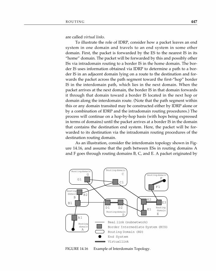
are called virtual links.To illustrate the role of IDRP, consider how a packet leaves an end
system in one domain and travels to an end system in some otherdomain. First, the packet is forwarded by the ES to the nearest IS in its“home” domain. The packet will be forwarded by this and possibly otherISs via intradomain routing to a border IS in the home domain. The bor-der IS uses information obtained via IDRP to determine a path to a bor-der IS in an adjacent domain lying on a route to the destination and for-wards the packet across the path segment toward the first-“hop” borderIS in the interdomain path, which lies in the next domain. When thepacket arrives at the next domain, the border IS in that domain forwardsit through that domain toward a border IS located in the next hop ordomain along the interdomain route. (Note that the path segment withinthis or any domain transited may be constructed either by IDRP alone orby a combination of IDRP and the intradomain routing procedures.) Theprocess will continue on a hop-by-hop basis (with hops being expressedin terms of domains) until the packet arrives at a border IS in the domainthat contains the destination end system. Here, the packet will be for-warded to its destination via the intradomain routing procedures of thedestination routing domain.
As an illustration, consider the interdomain topology shown in Fig-ure 14.16, and assume that the path between ESs in routing domains Aand F goes through routing domains B, C, and E. A packet originated by
R O U T I N G 447
FIGURE 14.16 Example of Interdomain Topology.
G C
B
D
A
E
F
B2
B1
A1
G1C1
D2D1
F1
E2
E1
E3
Real link (subnetwork)
Border Intermediate System (BIS)
Routing Domain (RD)
End System
Virtual link
Routing domain Routing domain
Routing domain
Routingdomain
Routingdomain
Routing domain
Routingdomain
an ES located in routing domain A and destined for an ES located inrouting domain F will first be routed by means of routing domain A’sintradomain routing procedures to border IS A1. Border IS A1 uses infor-mation obtained via IDRP to determine that the next border IS on thepath is B1, which is located in the next domain along the route. Since bor-der ISs A1 and B1 share a common subnetwork, border IS A1 can for-ward the packet directly to border IS B1 over a real link. Border IS B1uses information obtained via IDRP to select border IS B2 as the next bor-der IS along the path. (Note that the link between B1 and B2 is a virtuallink; hence, the forwarding of the packet along this link is accomplishedusing domain B’s intradomain routing procedures.) The process contin-ues through border ISs C1, E2, and E3, until the packet finally reachesborder IS F1, which is located in the routing domain (F) that contains thedestination end system. The packet is forwarded to the destination ESwithin routing domain F by means of domain F’s intradomain routingprocedures.
The IDRP Routing Algorithm—The routing algorithm employed by IDRPbears a certain resemblance to distance-vector (Bellman-Ford) routing.Each border IS advertises to its neighboring border ISs the destinationsthat it can reach. The IDRP routing algorithm augments the advertise-ment of reachable destinations with path attributes, information propagatedin IDRP routing control packets that describes various properties of thepaths to these destinations. To emphasize the tight coupling between thereachable destinations and the properties of the paths to these destina-tions, IDRP defines a route as a unit of information that consists of a pairingbetween a destination and the attributes of the path to that destination. Apath, expressed in terms of the domains that the routing information hastraversed so far, is carried in the RD_PATH attribute of the IDRP packetsthat distribute the routing information. Therefore, one may call IDRP apath-vector protocol, in which a border IS receives from each neighboringborder IS a vector that contains paths to a set of destinations.24
The IDRP routing algorithm is distributed: each border IS maintainspartial routing information, and routes are determined through the ex-change of information among border ISs and through local computationscarried out in each border IS. The IDRP routing algorithm assumes thateach routing domain has a globally unique routing domain identifier (RDI),which is simply a network entity title,25 and that the NSAP addresses
O P E N S Y S T E M S N E T W O R K I N G : T C P / I P A N D O S I448
24. The term path-vector protocol bears an intentional similarity to the term distance-vectorprotocol, in which a border IS receives from each of its neighbors a vector that contains dis-tances to a set of destinations.25. A routing domain identifier always identifies a particular domain for the purposes

assigned to ESs within the routing domains that participate in IDRP ex-changes are unique and unambiguous as well. Although this is a generalcharacteristic of NSAP addressing, and is also assumed by the OSI intra-domain routing protocol, it is mentioned explicitly here because IDRPhas no mechanism to enforce either of these two assumptions or even todetect whether they have been violated (which may result in incorrectprotocol operation).
Loop-free Routing in IDRP—IDRP is designed to ensure that, duringsteady-state operation (i.e., no interborder IS topological changes haveoccurred), routes computed by the border ISs participating in IDRP areloop-free. Since data packets flow in a direction opposite to the direction inwhich IDRP routing information flows, one way to satisfy this design ob-jective is to ensure that routing information does not loop. Because theRD_PATH attribute contains a list of routing domains expressed in termsof the routing domain identifiers of the domains that routing informationhas traversed so far, suppressing routing information looping is straight-forward: a border IS that receives a route must examine the RD_PATHattribute of the route and check whether the routing domain identifier ofthe border IS’s own routing domain is present in the attribute. If it is, theborder IS must not use this route.
As an illustration of how the loop-suppression mechanism works,consider a flow of routing information (route) that advertises reachabledestinations within routing domain F (see Figure 14.17). Assume thatroutes are selected in such a way that routing domain C prefers to reachdestinations in routing domain F via routing domain E, routing domain Bprefers to reach destinations in routing domain F via routing domain C(then via routing domain E), and routing domain D prefers to reach desti-nations in routing domain F via routing domain B (then via routingdomains C and E). Denote the routing domain identifiers of the participat-ing domains by B, X, �, E, and �. Border IS F1 originates the route andpropagates it to border IS E3. At this point, the RD_PATH attribute associ-ated with the route contains only one routing domain identifier—namely,the routing domain identifier of F (RD_PATH is < � >). Border IS E3 prop-agates this information to the other border ISs within its own domain—namely, E1 and E2. As E2 propagates the route to border IS C1, it updatesthe RD_PATH attribute by appending to it the routing domain identifierof its own routing domain (RD_PATH becomes < �, E >). Likewise, whenC1 propagates the route to border IS B2, it appends the routing domain
R O U T I N G 449
of IDRP but does not necessarily convey any information about the NSAP addresses of theend systems within the domain.
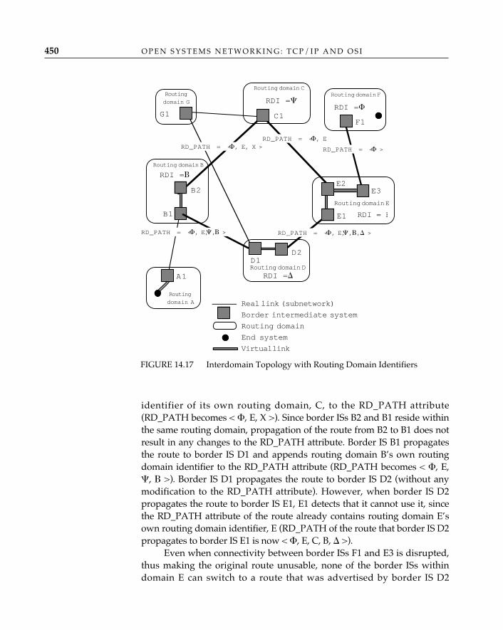
identifier of its own routing domain, C, to the RD_PATH attribute(RD_PATH becomes < �, E, X >). Since border ISs B2 and B1 reside withinthe same routing domain, propagation of the route from B2 to B1 does notresult in any changes to the RD_PATH attribute. Border IS B1 propagatesthe route to border IS D1 and appends routing domain B’s own routingdomain identifier to the RD_PATH attribute (RD_PATH becomes < �, E,�, � >). Border IS D1 propagates the route to border IS D2 (without anymodification to the RD_PATH attribute). However, when border IS D2propagates the route to border IS E1, E1 detects that it cannot use it, sincethe RD_PATH attribute of the route already contains routing domain E’sown routing domain identifier, E (RD_PATH of the route that border IS D2propagates to border IS E1 is now < �, E, C, B, � >).
Even when connectivity between border ISs F1 and E3 is disrupted,thus making the original route unusable, none of the border ISs withindomain E can switch to a route that was advertised by border IS D2
O P E N S Y S T E M S N E T W O R K I N G : T C P / I P A N D O S I450
FIGURE 14.17 Interdomain Topology with Routing Domain Identifiers
RD F
Routing domain C
Routing domain B
Routing domain D
Routing
domain A
Routing domain E
Routing domain F
B2
B1
A1
Routing
domain G
G1 C1
D2D1
F1
E2
E1
E3
Real link (subnetwork)
Border intermediate system
Routing domain
End system
Virtual link
RDI = E
RDI =�
RDI =�
RDI =�
RD_PATH = <� >
RD_PATH = <�, E RD_PATH = <�, E, X >
RD_PATH = <�, E,�, � > RD_PATH = <�, E,�,�,� >
RDI =�
(since such a route would involve routing information looping). (Notethat we have traced only one flow of routing information in this exam-ple. Readers are encouraged to trace other flows to acquire a feel for howthe routing process converges.)
Selecting an Optimal Route—IDRP does not require all routing do-mains to have identical criteria (policies) for route selection. IDRP doesnot even have a notion of a globally agreed upon metric that all thedomains must use for route selection. Moreover, the route-selection poli-cies used by one routing domain are not necessarily known to any otherrouting domain. To maintain the maximal degree of autonomy and inde-pendence among routing domains, each routing domain that participatesin IDRP may have its own view of what constitutes an optimal route.This view is based solely on local domain route-selection policies and theinformation carried in the path attributes of a route.
Note that when presented with exactly the same set of possibleroutes to a given destination, different routing domains may choose dif-ferent routes from the set. As an example, consider again the interdo-main topology shown in Figures 14.16 and 14.17 and assume that routingdomains C and D both have a route to destinations in routing domain F(both of which go through domain E). When routing domains C and Dadvertise this information to routing domains B and G, routing domain Bmay select the route offered by C, whereas routing domain G may selectthe route offered by D, despite the fact that C advertises exactly the sameroute to both B and G.
The following essential properties of the IDRP algorithm make itpossible to provide loop-free steady-state routing even in the presence ofindependent route-selection policies that need not be known outside adomain:
• Routing information distribution is preceded by the computationover the information.
• Only the results of the computation are distributed to other border ISs.• Suppression of routing information looping does not depend on the
presence of a globally agreed upon, monotonically increasing metric.
Thus, the only thing that is needed to provide consistent operationacross multiple routing domains is to standardize the mechanism usedto exchange the results of the route-selection procedure (the results ofthe route computation) while allowing the policies that affect route selec-tion to be of local significance only (nonstandard).26
R O U T I N G 451
26. This elegant and succinct observation was made by Ross Callon.
Restricting Transit Traffic—Providing ubiquitous connectivity withinthe global OSI internetwork implies that a domain may need to share itsown transmission and switching facilities (links, subnetworks, and ISs)with other domains, as well as rely on the willingness of other domainsto share theirs. Of course, once sharing exists, the ability to control itbecomes an important issue; there is always a cost associated with de-ploying and managing transmission and switching facilities, and the ad-ministrator responsible for these facilities must be able to control andaccount for their use, particularly by parties outside the scope of his orher own local user base.
One such control mechanism is the ability to restrict transit traffic,or prohibit it entirely, for a particular set of domains or for all other do-mains. In such cases, a domain is said to employ transit restrictions (transitpolicies) as a way of controlling the use of its facilities.27
Transit Policies Supported by IDRP—The fundamental technique usedby IDRP in support of transit policies is controlled distribution of routinginformation. This technique is based on a simple observation: when apacket’s flow is determined by the routing information present in borderISs, the direction of this flow is opposite to the direction of the routinginformation flow between the border ISs. Controlling routing informa-tion flows allows restriction of packet flows, which, in effect, imposestransit policies.28 (In the extreme case in which there are no routes overwhich a packet may be forwarded, the packet is discarded.)
Selective Advertisement of Routing Information—IDRP provides sev-eral mechanisms with various degrees of granularity and sophisticationthat allow a routing domain to control the distribution of routing infor-mation, thus providing control over its own transit traffic. The simplestmechanism is to have a border IS within a domain announce only a sub-set (or possibly none) of the routes that it uses to any border ISs in adja-cent domains. Note that a border IS may announce a different subset toborder ISs in different adjacent domains, so as to grant to some routingdomains a specific set of transit privileges and to others none.
To illustrate how this mechanism can be applied in the context ofthe topology illustrated in Figure 14.16, consider the following example.If border IS B1 has a route to destinations in routing domain F (which
O P E N S Y S T E M S N E T W O R K I N G : T C P / I P A N D O S I452
27. Examples of domains that rely heavily on transit policies are the backbone networkssponsored by agencies of the U.S. federal government, such as the Energy SciencesNetwork (ESnet), the NASA Science Internet (NSI), and the National Science FoundationNetwork (NSFnet).28. This technique was pioneered in the NSFnet backbone phase II (RFC 1104; RFC 1092).
may traverse, for example, routing domains C and E), but does not an-nounce this route to border IS A1, then no packets originated from an ESin routing domain A and destined for an ES in routing domain F will tra-verse the facilities that are under the control of routing domain B. Thisimposes a transit policy that prevents transit traffic from routing domainA to routing domain F from flowing through routing domain B. Thesame border IS B1 may, however, announce a route to destinations inrouting domain F to border IS D1, thus allowing transit traffic flowingbetween routing domains D and F to traverse routing domain B. Fur-thermore, by making the distribution of routing information depend onthe contents of the RD_PATH attribute, this mechanism may be extendedto take into account not only the origin and the destination of traffic butthe intervening path (in terms of routing domains) as well.
This mechanism works well if one wants to restrict transit trafficbetween sources that are within routing domains immediately adjacentto one’s own routing domain and destinations that are in some other (andnot necessarily adjacent) routing domain. However, to impose a moregeneral transit policy, IDRP provides another mechanism, one that ex-plicitly controls the distribution of routing information, thereby enablinga domain to restrict the scope of potential recipients of the routing infor-mation that flows through it. The scope may be specified by using a dis-tribution inclusion list (DIST_LIST_INCL) path attribute, which allows theenumeration of the potential recipients of the routing information (iden-tified by their routing domain identifiers), or a distribution exclusion list(DIST_LIST_EXCL) path attribute, which allows the enumeration of thedomains that shall be excluded from receiving the routing information.The mechanism provided by the DIST_LIST_INCL andDIST_LIST_EXCL path attributes imposes no restrictions on the relativeplacement of the source and destination domains of the transit traffic thatmust be restricted.
Referring again to Figure 14.16, suppose that routing domain C iswilling to carry transit traffic destined for any ES in routing domain F, aslong as the traffic does not originate from any of the ESs in routingdomain A. To impose such a transit policy, border IS C1 must attach aDIST_LIST_EXCL path attribute that contains A’s routing domain identi-fier to the route that it advertises to border IS B2 (DIST_LIST_EXCL ofthe advertised route shall be < A >). Border IS B2 will propagate thisroute, together with the DIST_LIST_EXCL attribute, to border IS B1.Although B1 may now propagate this route to border IS D1, it may notsend it to border IS A1, since A1 belongs to the routing domain A, whichis listed in the DIST_LIST_EXCL attribute of the route.
R O U T I N G 453
The ability to control the distribution of routing informationprovides an organization with corresponding control over the
way in which its resources may be used, while facilitating the interconnection ofmultiple organizations—thereby satisfying a major objective of OSI routing. Itremains to be seen whether the controls that are available in IDRP are sufficientor whether the deployment of a more elaborate control system, such as that pro-vided by the source-routed interdomain policy routing (IDPR) protocol, will benecessary.
Routing Domain Confederations—To achieve good scaling characteris-tics, IDRP provides a mechanism that allows a set of connected routingdomains to be grouped together and treated as a unit. Such a grouping ofdomains, called a routing domain confederation (RDC), is defined andestablished by means that are beyond the scope of IDRP.29 From the out-side, a routing domain confederation (hereafter, simply “confederation”)looks like a single routing domain: routing domains outside the confed-eration cannot tell whether the confederation is just a single domain or acollection of domains. This mechanism is inherently recursive, so that amember of a confederation may be either a routing domain or a set ofrouting domains that themselves form a confederation. Confederationsmay be nested, disjoint, or overlapped. The protocol does not place anytopological restrictions on the way in which confederation boundariesare defined, nor on the number of confederations to which a single do-main may belong.
Routing domain confederations are identified by routing domain con-federation identifiers that are taken from the same address space as therouting domain identifiers used to identify individual routing domains.The protocol assumes that all the border ISs that belong to a confedera-tion are statically preconfigured with both the routing domain identifierof their routing domain and the routing domain confederation identifierof the confederation. If a routing domain belongs to more than one con-federation, then the static information must include information aboutthe nested/disjoint/overlap relationships that exist between each pair ofconfederations. No other requirements are imposed on the confederationmembers. For example, different confederation members may advertisedifferent routes to a given destination—there is no need to have consis-tent route-selection policies for all the members of a confederation. Dif-ferent members may also impose different transit policies—there is no
✧AHA✧
O P E N S Y S T E M S N E T W O R K I N G : T C P / I P A N D O S I454
29. Specifically, IDRP does not suggest or recommend any principles, operating proce-dures, or policies that might be used by administrative domains which attempt to establishbilateral or multi-organizational routing relationships.
need for an a priori agreement on the transit policies that will be imposedby individual members.
Note that how one establishes a routing confederation is outside thescope of the protocol; however, the protocol explicitly recognizes a con-federation’s boundaries by taking specific actions when routing informa-tion enters and exits a confederation. Specifically, routing informationthat enters a confederation is marked by appending a special RD_PATHpath segment (either ENTRY_SET or ENTRY_SEQUENCE), followed bythe routing domain confederation identifier of the entered confederation,to the RD_PATH attribute.30 As routing information exits a confedera-tion, the RD_PATH attribute is scanned in the reverse direction: the pro-tocol searches for the ENTRY_SET or ENTRY_SEQUENCE path segmentthat contains the routing domain confederation identifier of the confed-eration that is about to be exited. Exiting a confederation results in removing all the domains within the confederation that the routinginformation traversed, leaving only the routing domain confederationidentifier, thereby reducing the amount of information carried in theRD_PATH attribute.
The ability to group routing domains into confederations providesa powerful mechanism for routing information aggregation and abstrac-tion, which, in turn, makes IDRP scalable to a practically unlimited num-ber of routing domains. The formation of confederations can keep theRD_PATH information from growing beyond a manageable size (andfrom preserving topological details that may be irrelevant in a very largeinternetwork). Similarly, transit policies may be expressed in terms ofconfederations rather than individual domains.
Using Confederations to Support Transit Policies—Relations betweenconfederations—expressed in terms of nesting, disjoint, or overlap—maybe used to impose certain types of transit policies that otherwise would bedifficult to support. Such policies are imposed via a “two-phase” rule thatstates that once routing information enters a confederation, it cannot exitthe confederation. To record the fact that routing information has entereda confederation, IDRP uses the HIERARCHICAL_RECORDING pathattribute. The distribution of the routing information is determined by thevalue of the attribute and by the flow of the information. Specifically, if a
R O U T I N G 455
30. Recall that the RD_PATH attribute is defined as a sequence of path segments. IDRPsupports four distinct types of path segments: RD_SEQ (an ordered set of domains or con-federations), RD_SET (an unordered set of domains or confederations), ENTRY_SEQ (anordered set of entered but not exited confederations), and ENTRY_SET (an unordered setof entered but not exited confederations).
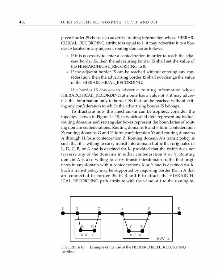
given border IS chooses to advertise routing information whose HIERAR-CHICAL_RECORDING attribute is equal to 1, it may advertise it to a bor-der IS located in any adjacent routing domain as follows:
• If it is necessary to enter a confederation in order to reach the adja-cent border IS, then the advertising border IS shall set the value ofthe HIERARCHICAL_RECORDING to 0.
• If the adjacent border IS can be reached without entering any con-federation, then the advertising border IS shall not change the valueof the HIERARCHICAL_RECORDING.
If a border IS chooses to advertise routing information whoseHIERARCHICAL_RECORDING attribute has a value of 0, it may adver-tise this information only to border ISs that can be reached without exit-ing any confederation to which the advertising border IS belongs.
To illustrate how this mechanism can be applied, consider thetopology shown in Figure 14.18, in which solid dots represent individualrouting domains and rectangular boxes represent the boundaries of rout-ing domain confederations. Routing domains E and F form confederationX; routing domains G and H form confederation Y; and routing domainsA through H form confederation Z. Routing domain A’s transit policy issuch that it is willing to carry transit interdomain traffic that originates inL, D, C, B, or A and is destined for K, provided that the traffic does nottraverse any of the domains in either confederation X or Y. Routingdomain A is also willing to carry transit interdomain traffic that origi-nates in any domain within confederations X or Y and is destined for K.Such a transit policy may be supported by requiring border ISs in A thatare connected to border ISs in B and E to attach the HIERARCH-ICAL_RECORDING path attribute with the value of 1 to the routing in-
O P E N S Y S T E M S N E T W O R K I N G : T C P / I P A N D O S I456
FIGURE 14.18 Example of the use of the HIERARCHICAL_RECORDINGAttribute
L D C B A K
RDC ZRDC XRDC Y
H G F E
formation that they receive from border ISs in K prior to propagatingthis information to border ISs in routing domains B or E. As a result,routing domain F would not be allowed to propagate routing informa-tion to routing domain B that traversed routing domains A and E.Likewise, routing domain H would not be allowed to propagate routinginformation to routing domain D that traversed routing domains A, B, C,and G. That leaves routing domain B with routing domain A as the onlypossible route to K, and leaves routing domain C as the only possiblechoice that goes via B and A, and routing domain D as the only possiblechoice that goes via C, B, and A.
Using the HIERARCHICAL_RECORDING path attribute in con-junction with the formation of routing domain confederations as a wayof implementing transit policies creates an environment that significantlyenhances an administrator’s ability to assess the effect of changes ininterdomain connectivity on interdomain routing. For example:
• Changes in the connectivity between domains that are located in aregion in which two or more routing domain confederations over-lap will not affect routing between domains outside the overlap.This is because border ISs located in routing domains within theoverlap cannot propagate routes between domains located outsidethe overlap.
• Changes in the connectivity between routing domains within a con-federation cannot affect routing between domains outside the con-federation, since routing domains that form a confederation cannotbe used for transit traffic between routing domains outside the con-federation.
• Changes in the connectivity between a border IS that belongs to adomain within a confederation and a border IS that belongs to adomain outside the confederation have no effect on routing be-tween the domain outside the confederation and any other domainoutside the confederation.
Handling Reachability Information—Recall that in the context of IDRP,a route is defined as a pairing between a set of reachable destinationsand the attributes of the path to those destinations. The set of reachabledestinations is called network layer reachability information (NLRI).
IDRP expresses network layer reachability information in terms ofNSAP address prefixes. Such an encoding provides a flexible and concisemechanism for describing a set of reachable destinations. A set coveredby an NSAP address prefix may be as small as a single end system or aslarge as a collection of all end systems within a confederation consisting
R O U T I N G 457
of multiple routing domains. If NSAP addresses are assigned in a hierar-chical fashion, and the address assignment hierarchy is congruent withinterdomain topology, the ability to express network layer reachabilityinformation in terms of NSAP address prefixes provides a powerful toolfor reducing the amount of reachability information that must be carriedand processed by the protocol. This reduction, accomplished by IDRP’sroute-aggregation procedures, allows IDRP to combine several routesinto a single route. Part of the route-aggregation procedure involves theaggregation of network layer reachability information, in which a set oflonger address prefixes is aggregated into a single shorter address prefix.
Supporting Multiple Routes to a Destination—IDRP allows a border ISto support multiple routes to a destination, based on the ability of CLNPto carry quality of service and security parameters (see Chapter 13). Apair of border ISs may exchange not one, but multiple “path vectors” tothe same destination, with each vector being tagged by its distinguishingpath attributes. This tagging allows a border IS to construct multiple for-warding tables, one for each set of distinguishing attributes associatedwith individual path vectors. When a border IS needs to forward a packet,it checks for the presence of quality of service or security parameters inthe packet and, if any are present, maps them into a corresponding set ofdistinguishing attributes. To determine the next hop on a path to a desti-nation, the border IS uses the forwarding table tagged with the appropri-ate distinguishing attributes. To ensure consistent forwarding across mul-tiple domains, IDRP standardizes on the mapping between quality ofsevice and security parameters supported in CLNP and the distinguish-ing attributes that are defined in IDRP.
Conceptually, one may think of a set of distinguishing attributes de-fined in IDRP as a set of “route colors.” Similarly, one may think of thequality of service and security parameters defined in CLNP as a set of“packet colors.” Tagging path vectors with appropriate distinguishingattributes may be viewed as “route coloring”; specifying quality of ser-vice or security parameters in CLNP packets may be viewed as “packetcoloring.” Consistent mapping between a route’s colors and a packet’scolors across domains ensures correct forwarding.
Like the quality of service and security parameters in CLNP—whichpermit the use of source-specific, destination-specific, and global parame-ter values—route and packet colors also have a scope. Specifically, themeaning of a color may be defined only within the scope of a source ordestination ES, or a color may have global significance. The scope of thesource- and destination-specific quality of service and security distin-
O P E N S Y S T E M S N E T W O R K I N G : T C P / I P A N D O S I458
guishing attributes in IDRP with respect to their significance for forward-ing is determined by the source addresses and destination addresses,respectively. The scope of such distinguishing attributes as cost, residualerror rate, and capacity is global; that is, their significance for forwardingdoes not depend on the source or destination addresses in the CLNPpackets.
IDRP requires all the border ISs within a single domain to agree onthe supported distinguishing attributes. However, the protocol does notrequire all the domains within the global OSI environment to supportthe same set of distinguishing attributes. In other words, the decision tosupport or not support a particular set of distinguishing attributes is leftto a domain’s local administration.
Having the ability to support multiple routes to a destination pro-vides IDRP with a flexible and powerful scheme for supporting variousforwarding granularities, including source- and destination-sensitive for-warding.
Support for multiple routes to a destination allows IDRP totake into account factors such as the cost or quality of service
associated with different routes; because “someone is paying,” support for suchfeatures is critical to interdomain routing.
Routing Information Exchange—IDRP packets (IDRP PDUs) are carriedin the data field of CLNP packets. A border IS that participates in IDRPexchanges routing information (routes) with its neighboring border ISsin the form of IDRP update packets.
The set of neighbors is partitioned into two categories: internal andexternal. The internal neighbors are the border ISs that belong to thesame routing domain as the local border IS. The external neighbors arethe border ISs that belong to different routing domains but share a com-mon subnetwork with the local border IS.
IDRP requires all border ISs within a domain to maintain pairwiseconnections with each other, in effect creating a complete mesh of bor-der-IS to border-IS connections. Although this appears to be a significantburden, careful analysis shows that such a mesh has no impact on over-head, other than maintaining state information for each of the border ISswithin a domain. This overhead will usually be negligible compared tothe amount of interdomain routing information that a border IS needs tohandle.
Routing information exchange in IDRP may be modeled as a two-phase procedure. A border IS first selects the best route among the routes
✧AHA✧
R O U T I N G 459
received from all its external neighbors and advertises this route to all itsinternal neighbors. In the second phase, a border IS selects the best routefrom all the routes received from all its neighbors, both external andinternal, and advertises this route to all its external neighbors (subject, ofcourse, to constraints on dissemination of routing information). To achieveconsistency between border ISs within a domain, a border IS that sends aroute to an internal neighbor attaches the ROUTE_SEPARATOR pathattribute to the route. This attribute carries the metric that the border ISassigns to that route. The receiving border IS may use this information tocheck whether its own route selection policies are consistent with the oneof the sending border IS.
The IDRP routing information dissemination algorithm that con-trols the exchange of routing information (update packets) between bor-der ISs is based on the technique of incremental updates, in which after aninitial exchange of complete routing information, a pair of border ISsexchange only changes to that information. This technique helps to con-serve a significant amount of resources (processor cycles and bandwidth),which is critical when dealing with an environment consisting of a largenumber of domains. Support for incremental updates requires reliableinformation exchange between participating border ISs. IDRP supportsthis reliability by a combination of sequence numbers assigned to updatepackets, explicit acknowledgments, and retransmission of unacknowl-edged update packets. In addition to incremental updates, IDRP pro-vides a mechanism to perform a complete update of the routing informa-tion in either solicited or unsolicited mode (this is done by using refreshpackets).
The IDRP routing information dissemination procedure is com-pletely event-driven and dynamic. The two possible events that may trig-ger the dissemination of (new) routing information are the establishmentof a new session with a neighboring border IS and the selection of newroutes by the local border IS as a result of either receiving an updatepacket from one of its neighbors or the deletion of all the routes receivedfrom a neighbor due to loss of the neighbor.
IDRP in Large Public and Private Data Networks—For domains thatemploy general mesh topology subnetwork technology, such as X.25 orSwitched Multimegabit Data Service networks (see Chapter 15), IDRPavoids the use of border ISs within such domains for packet forwardingaltogether; rather, IDRP uses border ISs solely as a mechanism to puttransit and route-selection policies in place. To accomplish this, a borderIS is allowed to pass a route to another border IS located in an adjacent
O P E N S Y S T E M S N E T W O R K I N G : T C P / I P A N D O S I460
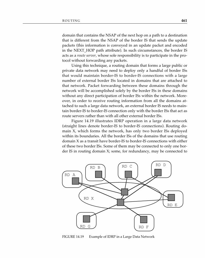
domain that contains the NSAP of the next hop on a path to a destinationthat is different from the NSAP of the border IS that sends the updatepackets (this information is conveyed in an update packet and encodedin the NEXT_HOP path attribute). In such circumstances, the border ISacts as a route server, whose sole responsibility is to participate in the pro-tocol without forwarding any packets.
Using this technique, a routing domain that forms a large public orprivate data network may need to deploy only a handful of border ISsthat would maintain border-IS to border-IS connections with a largenumber of external border ISs located in domains that are attached tothat network. Packet forwarding between these domains through thenetwork will be accomplished solely by the border ISs in these domainswithout any direct participation of border ISs within the network. More-over, in order to receive routing information from all the domains at-tached to such a large data network, an external border IS needs to main-tain border-IS to border-IS connection only with the border ISs that act asroute servers rather than with all other external border ISs.
Figure 14.19 illustrates IDRP operation in a large data network(straight lines denote border-IS to border-IS connections). Routing do-main X, which forms the network, has only two border ISs deployedwithin its boundaries. All the border ISs of the domains that use routingdomain X as a transit have border-IS to border-IS connections with eitherof these two border ISs. Some of them may be connected to only one bor-der IS in routing domain X; some, for redundancy, may be connected to
R O U T I N G 461
FIGURE 14.19 Example of IDRP in a Large Data Network
RD X
RD A
RD B RD C RD D
RD E
RD G RD F
both. If a border IS in routing domain A advertises to a border IS in rout-ing domain X a route to a destination, then the border IS in routingdomain X may readvertise this route to border ISs in other domains, suchas border ISs in routing domains C or G, with the NSAP of the border ISin routing domain A, rather than its own, as the next hop. Thus, whenthe border IS in routing domain G needs to forward a packet to that des-tination, it may send it directly to the border IS in routing domain A. Tofacilitate forwarding, the information about the next-hop NSAP may befurther augmented with the list of SNPAs associated with that NSAP.Observe that although border ISs in the domains attached to routingdomain X have sufficient routing information to send packets directly toeach other through routing domain X, distribution of this informationdoes not require these border ISs to have border-IS to border-IS connec-tions with each other. Instead, the distribution is accomplished as a resultof maintaining border-IS to border-IS connections with only border ISs inrouting domain X.
In the terminology of TCP/IP routing, “interdomain” routing becomes“interautonomous system” routing. The first exterior gateway protocol (RFC904) assumed a tree structure for the Internet: lots of midlevel networksbranching off the core or backbone autonomous system, and lots of net-works branching off the midlevel networks. In principle, leaf networksforwarded IP packets to midlevels if they didn’t know how to get to adestination, midlevels forwarded IP packets to the core if they didn’tknow how to get to a destination, and the omniscient core dealt with for-warding IP packets out through the branches to the leaves.
All well and good, right? Well, not exactly. First, the deployedInternet topology did not conform to the model: links were deployed andused to route packets between the leaf networks and between midlevels,and (horrors!) more backbones were introduced! (So much for the notionof a “core.”) Second, and equally disconcerting, the EGP model requiredthat the core know everything about the connectivity of the topology (amajor shortcoming of EGP was the fact that it functioned as both anintra- and interdomain routing protocol). EGP always distributed com-plete updates: as the Internet grew, the size of EGP “updates,” which aresent in single IP packets, became very large, and IP reassembly became abottleneck.31 EGP really didn’t address the issue of policy; “policies”were manually introduced by operators and applied as filters to EGP
O P E N S Y S T E M S N E T W O R K I N G : T C P / I P A N D O S I462
InterdomainRouting inTCP/IP
31. Recall that both OSPF and integrated IS-IS try to avoid IP fragmentation andreassembly by allowing incremental (partial) updates.
routing updates as they were received. Finally, and most damaging ofall, EGP couldn’t detect loops (it insisted that the topology have none). Inshort, EGP simply could not cope, nor could the network administratorsusing it.
Enter the border gateway protocol (first specified in RFC 1105; subse-quent versions, denoted BGP-1 through BGP-3, have appeared in RFC1163 and RFC 1267). Incrementally, versions of BGP have freed and willfree the Internet from the restrictive notion of a tree-based topology forinter-AS routing. BGP versions 3 and 4 (an RFC in preparation) offer asubset of the features for IP that IDRP offers for CLNP (not particularlysurprising, since it is the ancestor of the ISO IDRP [Rekhter 1991; Tsu-chiya 1991]). Like IDRP, BGP uses a path/distance-vector method ofroute computation and distribution: at start-up, BGP speakers (the equiva-lent of border ISs in IDRP) exchange their complete routing informationbases and subsequently distribute incremental updates of in-use auto-nomous system paths only. Like IDRP’s RD_PATH, which is composedof routing domain identifiers of real and virtual paths between borderISs, an autonomous system path, composed of Internet network numbers,may be real or virtual; however, the terms used in BGP are external orinternal paths. As BGP speakers distribute reachability information,including path attributes, they compose and forward a complete list ofautonomous systems that have already forwarded this routing informa-tion; like IDRP’s compilation of the RD_PATH, this is done to avoidlooping. Whereas IDRP operates point-to-point between border ISs overCLNP and supports reliability by a combination of sequence numbers,explicit acknowledgments, and retransmission of unacknowledgedupdate packets in IDRP proper, BGP speakers operate pairwise over TCPconnections and leave reliability to TCP.
Interdomain routing protocols like BGP and IDRP are fine for mostforms of traffic enforcement, especially those that can be generally ap-plied to a majority of users to facilitate routing domain interconnection;in such cases, the routing overhead—interdomain distribution and routecomputation—is more than justified, since these policies are widelyused. Both BGP-4 and IDRP are expected to scale well enough to accom-modate general needs for the foreseeable future.
There are other types of interdomain routes, however, that meritspecial consideration. For example, a research branch of one companymay collaborate with another, perhaps even a competitor, to advance aparticular technology. In cases such as these, it may be important to offerconnectivity between the research laboratories of the two companies, but
R O U T I N G 463
Final Commentson PolicyRouting
it remains equally important to both administrations that they retain theability to prohibit access to other parts of their enterprise networks.Another example is one in which a company maintains networks in sev-eral countries; quite often, international law frowns on such companies’providing intertransit services to third parties. In small doses, policiessuch as these can be managed by IDRP or BGP, but it is quite obviousthat dealing with every policy eccentricity of every interdomain pairingof communicating hosts with hop-by-hop routing will quickly tendtoward unmanageability; IDRP and BGP don’t scale that well! In otherwords, there is a need for “exception-case” interdomain routing.
The interdomain policy routing (IDPR) architecture and protocol (RFCsin preparation) provide the means whereby special restrictions on inter-domain routes may be specified or “demanded” at the source; hence, thename source-demand routing. The current version of IDPR uses link-staterouting to distribute interdomain reachability and policy informationbetween policy gateways, which, like IDRP’s border ISs and BGP’s speak-ers, are routers that are directly connected across administrative domains(here, the relationship is called a virtual gateway). The policy gateways ineach domain receive interdomain link-state advertisements and calculateroutes based on the topology map they have received according to what-ever policies the administration wishes to enforce. When a packet is to beforwarded with certain policy considerations, it is forwarded to a policygateway within the routing domain of that packet’s source. This “source”policy gateway calls upon a route server to assist in setting up a routedetermined by the source policy gateway; a route-setup packet thatdescribes the interdomain path selected by the source policy gateway isforwarded to all the policy gateways that must maintain the route in thetransit (and destination) routing domains. A path or flow identifier isassigned to this interdomain route, and all packets that are to be for-warded across this route are encapsulated in an IP datagram that carriesthe flow identifier as additional header information.
“Unified” Interdomain Routing—Note that these two different methodsof interdomain routing overlap, in the sense that nearly the same types ofcontrols can be imposed on interdomain traffic using either method (RFC1322, 1992). However, it is not necessary to choose between the two meth-ods of interdomain routing; rather, each has its respective merits. RFC1322, A Unified Approach to Inter-domain Routing, suggests that in a robustinterdomain routing architecture, these two methods are complementary.“Hop-by-hop” or node-routing interdomain protocols are importantbecause they allow administrations to set policies for the largest percent-
O P E N S Y S T E M S N E T W O R K I N G : T C P / I P A N D O S I464
age of interdomain traffic and from the largest number of sources; i.e.,policies for the masses. Of course, since the node-routing protocols areexpected to support the masses, they must maintain routes that are oper-ational and under some administrative control, and they must also beable to adapt to topology changes, to keep the interdomain traffic flow-ing in the face of failures (IDRP and BGP have these characteristics).
Source-demand routing protocols like IDPR are important becausethey allow administrations to build special routes that could be supportedby the “hop-by-hop” protocols, but at considerable routing expense/overhead. Having both methods available allows administrations to putin place policies that are generally needed while accommodating excep-tional circumstances. Balancing between the two is an important opera-tional matter. Since the routes maintained by source-demand routingprotocols are supposedly “special,” there is an assumption that they willbe used sparingly; indeed, if they become widely used, then the routinginformation should be distributed by node-routing protocols.
ConclusionThis chapter has discussed the routing principles, architecture, and pro-tocols of OSI and TCP/IP—in the process, illustrating how OSI routinghas benefited from what has been learned from the considerable experi-mentation and field experience with IP routing. The IP community hasdeveloped a hierarchy of routing functions and protocol in an evolution-ary fashion, by necessity (a consequence of its success) increasing therobustness and reach of its protocols and architecture to scale to millionsof hosts. The resulting IP routing architecture locates discovery and reach-ability among hosts and gateways in one functional tier, providing bestpaths between hosts within a single routing domain in a second tier, andproviding methods for routing between domains in a third tier. The OSIcommunity readily adopted this functional hierarchy, defining the threefunctional tiers of ES-IS, intradomain IS-IS, and interdomain IS-IS rout-ing. The benefit to the OSI community is that it won’t have to undergomany of the growing pains that have been endured by the IP communityand that it can support a routing environment that scales at least as wellas that of IP. The OSI community—and of course, the “tweeners”—haveattempted to return the favor by defining some useful improvements inOSI routing protocols that can be applied in IP-only or integrated rout-ing protocols as well.
R O U T I N G 465
Below the network layer, the architectural uniformity of the OSI refer-ence model partially breaks down. According to the OSI reference model,the role of the data link layer is to “provide for the control of the physicallayer, to detect and where possible, correct errors which may occur in aphysical connection established for bit transmission” (ISO/IEC 7498:1993). There is, however, a small problem: at the data link layer, thingsget very technology-specific. All sorts of technologies are used to connectcomputers, and there is an astonishingly large number of standards forthe data-link and physical layers that describe a trillion or so modem andelectrical interface standards. Some have been around for decades.Consider the venerable high level data link control (HDLC). Having pro-vided nearly two decades of wide-scale deployment and service overkilobit transmission facilities (the equally venerable V-series modems),HDLC is enjoying something of a rejuvenation in the form of frame relayservices.
Later technologies—notably, local area networks—improved on ear-lier technologies by introducing shared-medium, multipoint communica-tion; significantly higher bandwidth; low latency; and very low errorrates. Metropolitan area network (MAN) technologies, the asynchronoustransfer mode (ATM) platform for broadband integrated services, and thesynchronous optical network (SONET) technology are expected to furtherexpand the role of the data link layer, introducing constant bit rate andisochronous services (for voice and real-time video) and even greater(potentially gigabit) bandwidth.
This technology advance wreaked havoc on the poor souls respon-sible for providing service definitions for the data link and physical lay-
15 DATA LINK AND PHYSICAL LAYERS
467
ers of OSI (ISO/IEC 8886: 1992; ISO/IEC 10022: 1990). Ultimately, theparties involved quite literally threw their hands up in exasperation andprovided definitions that can be viewed as at best a “for completeness’ssake” effort. Truthfully, this is nothing to lose sleep over: given how fre-quently technologies are introduced, the data link and physical layer ser-vice definitions offer a snapshot of what these layers looked like at thetime of standardization, but they absolutely should not be interpreted asthe final word on what the data link and physical layers should be.
Some technologies—for example, point-to-point and HDLC-basedlinks—fit conveniently into the OSI reference model’s notion of a datalink. Advocates of local area networks, however, opined that LANs werericher in function than mere data links—they had globally uniqueaddressing, and it could even be argued that Medium Access Controlincluded routing functions. For a brief time, LANs led a truly schizo-phrenic existence: eventually, the “it’s a subnetwork technology” folkswere beaten into submission by the “it’s a data link” folks, and LANswere placed at the data link layer, along with point-to-point protocolslike ISO/IEC 7776, high level data link control, and CCITT Recommenda-tion X.21bis, Use on Public Data Networks of Data Terminal EquipmentDesigned for Interfacing to Synchronous V-series Modems. Metropolitan areanetworks—fiber distributed data interface (FDDI) and the distributedqueue dual bus (DQDB)—will undoubtedly share the same fate as LANs,and since politics will most certainly play a role in broadband integratedservices digital networks (BISDN), it is inevitable that one or more broad-band services will contend for roles in the network layer.
Not to worry: it will be possible to run IP and CLNP over all of them.
Taxonomy of Data Link StandardsConsistent with Tanenbaum’s (1988) taxonomy, data link and physicallayer standards for OSI generally fall into two categories:
1. Point-to-point connection standards describe the use of HDLC proce-dures (ISO/IEC 3309: 1991; ISO/IEC 4335: 1991; ISO/IEC 7809:1991) as a means of framing data for transmission over variousphysical media in single- and multilink configurations (ISO/IEC7478: 1984; ISO/IEC 7776: 1986).1
2. Multi access channel standards describe logical link control proce-
O P E N S Y S T E M S N E T W O R K I N G : T C P / I P A N D O S I468
1. There are more data link and physical layer standards that apply to OSI, to be
dures (ISO/IEC 8802-2: 1990) as well as physical access methodsand medium specifications for local and metropolitan area net-works: carrier sense multiple access with collision detection (CSMA/CD; ISO/IEC 8802-3: 1992), token-passing bus (ISO/IEC 8802-4:1990), and token ring (ISO/IEC 8802-5: 1990). Fiber distributed datainterface (ISO/IEC 9314-2: 1989) and distributed queue dual bus (IEEE802.6 1990) MAN complete the list.
These categories apply equally well to the Internet architecture.Although the nomenclature differs slighty—Internetters prefer the termnetwork interfaces over data link layer—the Internet community wiselyelected to treat anything and everything that IP could conceivably be runover as a network interface.
Point-to-Point Connection StandardsHDLC-based protocols remain the most common form of link-levelframing for point-to-point connection technologies; connection-orientedand datagram transmission (a.k.a. unnumbered information frames, or UI)are described among the HDLC classes of procedures. Both performerror detection using a 16- or 32-bit cyclic redundancy check.
Point-to-point subnetworks play an important role in both TCP/IPand OSI network connectivity. The standard for encapsulation ofInternet datagrams over point-to-point links is RFC 1331, the point-to-point protocol (PPP). RFC 1331 describes a convention for encapsulatingnetwork-layer protocols in full-duplex, asynchronous or synchronouslinks, using HDLC framing. The default 8-octet frame format defined inthe PPP (Figure 15.1) accommodates a maximum frame size of 1,500octets and specifies a 16-bit frame-check sequence. PPP uses an address-extension mechanism available in HDLC to specify a protocol field,which is used to identify network-layer protocols in a multiprotocol(OSI, TCP/IP, AppleTalk®, XNS/IPX, etc.) environment. PPP alsodescribes a link control protocol that can be used, for example, to negotiatemaximum receive frame size, to indicate that authentication must be per-formed using the specified authentication protocol, and to indicate to apeer that the link quality is to be monitored using the specified protocol.Finally, PPP provides a framework for the development of a set of net-
D A T A L I N K A N D P H Y S I C A L L A Y E R S 469
sure. Folts (1991) devotes entire volumes of a multivolume compendium of OSI standardsto the CCITT V-series and X-series recommendations. Halsall (1988) provides a college-text-level primer on these layers. And of course, there is always Tanenbaum (1988).
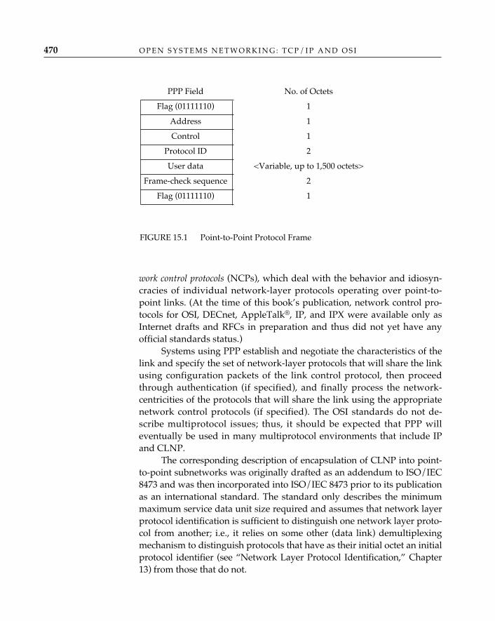
work control protocols (NCPs), which deal with the behavior and idiosyn-cracies of individual network-layer protocols operating over point-to-point links. (At the time of this book’s publication, network control pro-tocols for OSI, DECnet, AppleTalk®, IP, and IPX were available only asInternet drafts and RFCs in preparation and thus did not yet have anyofficial standards status.)
Systems using PPP establish and negotiate the characteristics of thelink and specify the set of network-layer protocols that will share the linkusing configuration packets of the link control protocol, then proceedthrough authentication (if specified), and finally process the network-centricities of the protocols that will share the link using the appropriatenetwork control protocols (if specified). The OSI standards do not de-scribe multiprotocol issues; thus, it should be expected that PPP willeventually be used in many multiprotocol environments that include IPand CLNP.
The corresponding description of encapsulation of CLNP into point-to-point subnetworks was originally drafted as an addendum to ISO/IEC8473 and was then incorporated into ISO/IEC 8473 prior to its publicationas an international standard. The standard only describes the minimummaximum service data unit size required and assumes that network layerprotocol identification is sufficient to distinguish one network layer proto-col from another; i.e., it relies on some other (data link) demultiplexingmechanism to distinguish protocols that have as their initial octet an initialprotocol identifier (see “Network Layer Protocol Identification,” Chapter13) from those that do not.
O P E N S Y S T E M S N E T W O R K I N G : T C P / I P A N D O S I470
PPP Field No. of Octets
Flag (01111110) 1
Address 1
Control 1
Protocol ID 2
User data <Variable, up to 1,500 octets>
Frame-check sequence 2
Flag (01111110) 1
FIGURE 15.1 Point-to-Point Protocol Frame
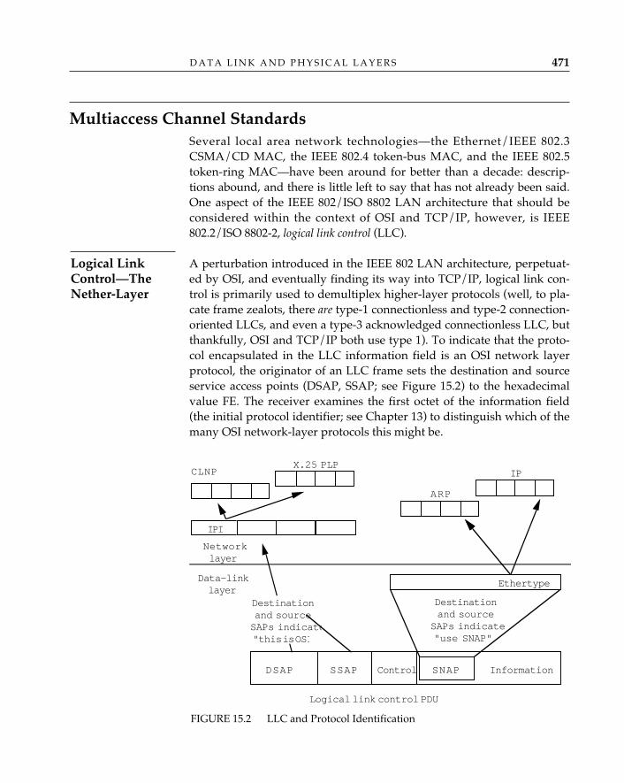
Multiaccess Channel StandardsSeveral local area network technologies—the Ethernet/IEEE 802.3CSMA/CD MAC, the IEEE 802.4 token-bus MAC, and the IEEE 802.5token-ring MAC—have been around for better than a decade: descrip-tions abound, and there is little left to say that has not already been said.One aspect of the IEEE 802/ISO 8802 LAN architecture that should beconsidered within the context of OSI and TCP/IP, however, is IEEE802.2/ISO 8802-2, logical link control (LLC).
A perturbation introduced in the IEEE 802 LAN architecture, perpetuat-ed by OSI, and eventually finding its way into TCP/IP, logical link con-trol is primarily used to demultiplex higher-layer protocols (well, to pla-cate frame zealots, there are type-1 connectionless and type-2 connection-oriented LLCs, and even a type-3 acknowledged connectionless LLC, butthankfully, OSI and TCP/IP both use type 1). To indicate that the proto-col encapsulated in the LLC information field is an OSI network layerprotocol, the originator of an LLC frame sets the destination and sourceservice access points (DSAP, SSAP; see Figure 15.2) to the hexadecimalvalue FE. The receiver examines the first octet of the information field(the initial protocol identifier; see Chapter 13) to distinguish which of themany OSI network-layer protocols this might be.
D A T A L I N K A N D P H Y S I C A L L A Y E R S 471
Logical LinkControl—TheNether-Layer
FIGURE 15.2 LLC and Protocol Identification
Data-linklayer
Networklayer
Information
Logical link control PDU
CLNP
SSAP ControlDSAP
IP
Destinationand sourceSAPs indicate"this is OSI
Destinationand source
SAPs indicate"use SNAP"
Ethertype
SNAP
ARP
IPI
X.25 PLP
When Ethernet was first developed, the last 2 octets of theMAC frame (the ethertype field) were used to identify higher-
layer protocols. When the technology was introduced into the IEEE 802 commit-tee so that it might become a standard LAN technology, the ethertype field of theMAC frame was abandoned in favor of a MAC frame-length field (ostensibly,the ethertype field was specific to Ethernet; given that the IEEE 802 committeewas attempting to standardize multiple MAC technologies, it seemed moreappropriate to have a MAC-independent means of identifying higher-layer pro-tocols—i.e., logical link control). The dual role of these octets would cause con-siderable difficulty if stations with IEEE 802.3 CSMA/CD and Ethernet MACswere to attempt to communicate if not for the fact that the values of the field arenonoverlapping: the maximum value of the length field in the IEEE 802.3 MACframe is slightly more than 1,500 octets, and the ethertype values are, conve-niently, integers greater than this value. Most implementations now recognizeboth techniques. Even though interoperability is accommodated, a rift wasformed between the Ethernet and IEEE 802 communities that persists today.
Initially, IEEE intended that values other than hexadecimal FEwould be assigned to deserving organizations; it didn’t take long, how-ever, to realize that a single octet (255 values) would not suffice to identifyall organizations requiring protocol/organization identifiers. Rather thanexpand the length of the LLC SAP fields, the IEEE 802.1 committeeadopted what is called the subnetwork access protocol (SNAP). The SNAPis itself identified by populating the destination and source service accesspoint fields with the hexadecimal value AA. This value indicates that anadditional 5 octets are appended to the 3-octet LLC type-1 frame to con-vey a 3-octet protocol identifier/organization identifier field and a 2-octetorganization-specific field. The existence of the SNAP doesn’t come closeto smoothing the feathers ruffled during the “ethertype versus IEEE802.3 frame length” debates; however, SNAP does have two redeemingvirtues:
1. For IP encapsulation in IEEE 802.x LANs (RFC 1042, 1988),switched multimegabit data service (RFC 1209, 1991), and fiber dis-tributed data interface (FDDI) (RFC 1188), the protocolidentifier/organization identifier field is set to 0, and the ethertypefield is conveyed in the remaining 2 bytes.
2. The addition of 5 octets to the 3-octet LLC type-1 field word-alignsthe header of the encapsulated network protocols for both 16- and32-bit machines.
✧AHA✧
O P E N S Y S T E M S N E T W O R K I N G : T C P / I P A N D O S I472
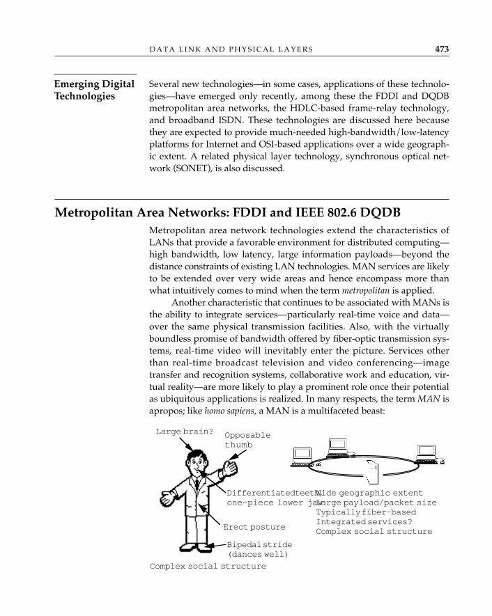
Several new technologies—in some cases, applications of these technolo-gies—have emerged only recently, among these the FDDI and DQDBmetropolitan area networks, the HDLC-based frame-relay technology,and broadband ISDN. These technologies are discussed here becausethey are expected to provide much-needed high-bandwidth/low-latencyplatforms for Internet and OSI-based applications over a wide geograph-ic extent. A related physical layer technology, synchronous optical net-work (SONET), is also discussed.
Metropolitan Area Networks: FDDI and IEEE 802.6 DQDBMetropolitan area network technologies extend the characteristics ofLANs that provide a favorable environment for distributed computing—high bandwidth, low latency, large information payloads—beyond thedistance constraints of existing LAN technologies. MAN services are likelyto be extended over very wide areas and hence encompass more thanwhat intuitively comes to mind when the term metropolitan is applied.
Another characteristic that continues to be associated with MANs isthe ability to integrate services—particularly real-time voice and data—over the same physical transmission facilities. Also, with the virtuallyboundless promise of bandwidth offered by fiber-optic transmission sys-tems, real-time video will inevitably enter the picture. Services otherthan real-time broadcast television and video conferencing—imagetransfer and recognition systems, collaborative work and education, vir-tual reality—are more likely to play a prominent role once their potentialas ubiquitous applications is realized. In many respects, the term MAN isapropos; like homo sapiens, a MAN is a multifaceted beast:
D A T A L I N K A N D P H Y S I C A L L A Y E R S 473
Emerging DigitalTechnologies
Large brain? Opposablethumb
Differentiated teeth,one-piece lower jaw
Wide geographic extentLarge payload/packet sizeTypically fiber-basedIntegrated services?Complex social structureErect posture
Bipedal stride(dances well)
Complex social structure
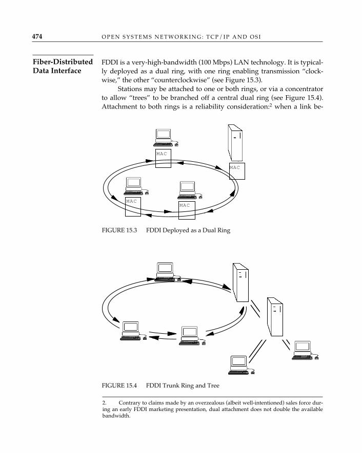
FDDI is a very-high-bandwidth (100 Mbps) LAN technology. It is typical-ly deployed as a dual ring, with one ring enabling transmission “clock-wise,” the other “counterclockwise” (see Figure 15.3).
Stations may be attached to one or both rings, or via a concentratorto allow “trees” to be branched off a central dual ring (see Figure 15.4).Attachment to both rings is a reliability consideration:2 when a link be-
O P E N S Y S T E M S N E T W O R K I N G : T C P / I P A N D O S I474
FIGURE 15.3 FDDI Deployed as a Dual Ring
Fiber-DistributedData Interface
MACMAC
MAC
MAC
2. Contrary to claims made by an overzealous (albeit well-intentioned) sales force dur-ing an early FDDI marketing presentation, dual attachment does not double the availablebandwidth.
FIGURE 15.4 FDDI Trunk Ring and Tree
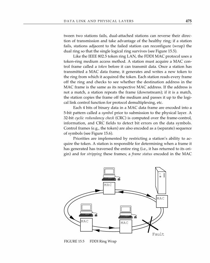
tween two stations fails, dual-attached stations can reverse their direc-tion of transmission and take advantage of the healthy ring; if a stationfails, stations adjacent to the failed station can reconfigure (wrap) thedual ring so that the single logical ring survives (see Figure 15.5).
Like the IEEE 802.5 token ring LAN, the FDDI MAC protocol uses atoken-ring medium access method. A station must acquire a MAC con-trol frame called a token before it can transmit data. Once a station hastransmitted a MAC data frame, it generates and writes a new token tothe ring from which it acquired the token. Each station reads every frameoff the ring and checks to see whether the destination address in theMAC frame is the same as its respective MAC address. If the address isnot a match, a station repeats the frame (downstream); if it is a match,the station copies the frame off the medium and passes it up to the logi-cal link control function for protocol demultiplexing, etc.
Each 4 bits of binary data in a MAC data frame are encoded into a5-bit pattern called a symbol prior to submission to the physical layer. A32-bit cyclic redundancy check (CRC) is computed over the frame-control,information, and CRC fields to detect bit errors on the data symbols.Control frames (e.g., the token) are also encoded as a (separate) sequenceof symbols (see Figure 15.6).
Priorities are implemented by restricting a station’s ability to ac-quire the token. A station is responsible for determining when a frame ithas generated has traversed the entire ring (i.e., it has returned to its ori-gin) and for stripping these frames; a frame status encoded in the MAC
D A T A L I N K A N D P H Y S I C A L L A Y E R S 475
FIGURE 15.5 FDDI Ring Wrap
Fault
MAC
MAC
MAC
MAC
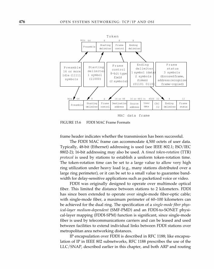
frame header indicates whether the transmission has been successful.The FDDI MAC frame can accommodate 4,500 octets of user data.
Typically, 48-bit (Ethernet) addressing is used (see IEEE 802.1; ISO/IEC8802-2); 16-bit addressing may also be used. A timed token-rotation (TTR)protocol is used by stations to establish a uniform token-rotation time.The token-rotation time can be set to a large value to allow very highring utilization under heavy load (e.g., many stations distributed over alarge ring perimeter), or it can be set to a small value to guarantee band-width for delay-sensitive applications such as packetized voice or video.
FDDI was originally designed to operate over multimode opticalfiber. This limited the distance between stations to 2 kilometers. FDDIhas since been extended to operate over single-mode fiber-optic cable;with single-mode fiber, a maximum perimeter of 60–100 kilometers canbe achieved for the dual ring. The specification of a single-mode fiber phys-ical-layer medium-dependent (SMF-PMD) and an FDDI-to-SONET physi-cal-layer mapping (FDDI-SPM) function is significant, since single-modefiber is used by telecommunications carriers and can be leased and usedbetween facilities to extend individual links between FDDI stations overmetropolitan area networking distances.
IP encapsulation over FDDI is described in RFC 1188; like encapsu-lation of IP in IEEE 802 subnetworks, RFC 1188 prescribes the use of theLLC/SNAP, described earlier in this chapter, and both ARP and routing
O P E N S Y S T E M S N E T W O R K I N G : T C P / I P A N D O S I476
FIGURE 15.6 FDDI MAC Frame Formats
Token
Preamble16 or moreidle (11111)symbols
Startingdelimiter1 symbol(11000)
Framecontrol8-bit typefield
(2 symbols)
Endingdelimiter
1 symbol (data)2 symbols(token)
(01101 01101)
PreambleStartingdelimiter
Framecontrol
Destinationaddress
Sourceaddress
Userdata
CRC32
Endingdelimiter
MAC data frame
PreambleStartingdelimiter
Framecontrol
Endingdelimiter
Bits 64 88 8
Framestatus
3 symbols(Errored frame,
address recognizedframe-copied)
Bits 64 8 8 16 or 48 16 or 48 32 4
Framestatus
120 <n 4500
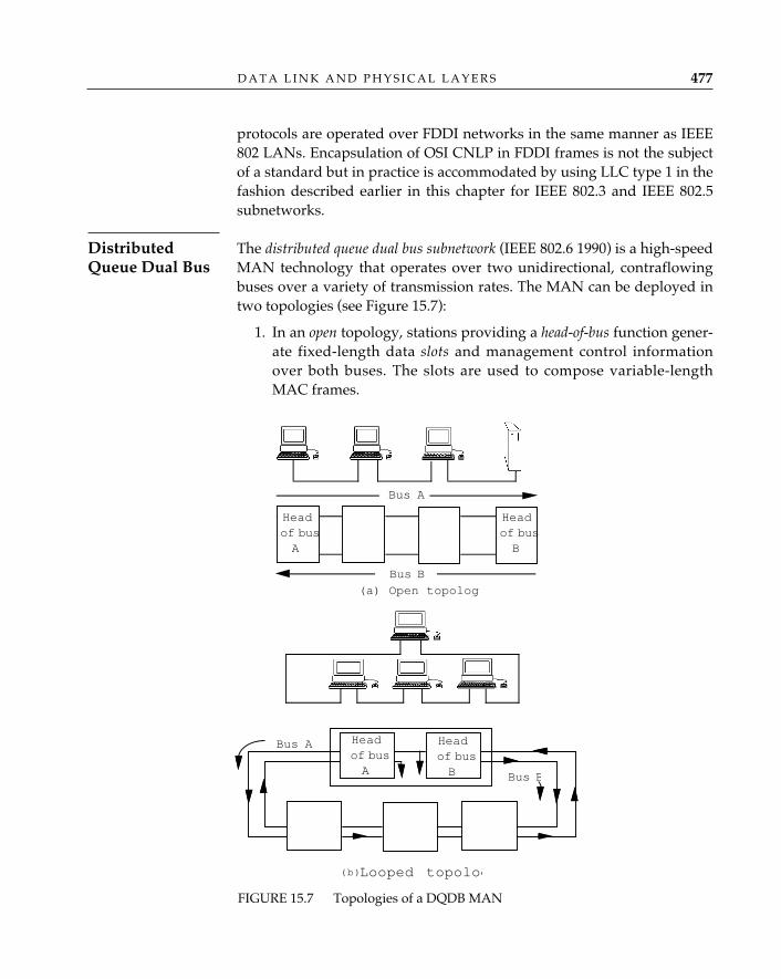
protocols are operated over FDDI networks in the same manner as IEEE802 LANs. Encapsulation of OSI CNLP in FDDI frames is not the subjectof a standard but in practice is accommodated by using LLC type 1 in thefashion described earlier in this chapter for IEEE 802.3 and IEEE 802.5subnetworks.
The distributed queue dual bus subnetwork (IEEE 802.6 1990) is a high-speedMAN technology that operates over two unidirectional, contraflowingbuses over a variety of transmission rates. The MAN can be deployed intwo topologies (see Figure 15.7):
1. In an open topology, stations providing a head-of-bus function gener-ate fixed-length data slots and management control informationover both buses. The slots are used to compose variable-lengthMAC frames.
D A T A L I N K A N D P H Y S I C A L L A Y E R S 477
DistributedQueue Dual Bus
Bus B
Headof busA
Headof busB
Headof busA
of BusB
(a) Open topology
Looped topolog
Bus A
Bus A
Bus B
Head
(b)
Headof busB
FIGURE 15.7 Topologies of a DQDB MAN
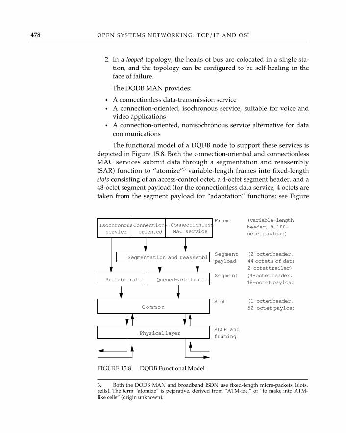
2. In a looped topology, the heads of bus are colocated in a single sta-tion, and the topology can be configured to be self-healing in theface of failure.
The DQDB MAN provides:
• A connectionless data-transmission service• A connection-oriented, isochronous service, suitable for voice and
video applications• A connection-oriented, nonisochronous service alternative for data
communications
The functional model of a DQDB node to support these services isdepicted in Figure 15.8. Both the connection-oriented and connectionlessMAC services submit data through a segmentation and reassembly(SAR) function to “atomize”3 variable-length frames into fixed-lengthslots consisting of an access-control octet, a 4-octet segment header, and a48-octet segment payload (for the connectionless data service, 4 octets aretaken from the segment payload for “adaptation” functions; see Figure
O P E N S Y S T E M S N E T W O R K I N G : T C P / I P A N D O S I478
FIGURE 15.8 DQDB Functional Model
Physical layer
Common
PLCP andframing
Slot (1-octet header,52-octet payload
Queued-arbitratedPrearbitratedSegment (4-octet header,
48-octet payload
ConnectionlessMAC service
Isochronousservice
Connection-oriented
Frame (variable-lengthheader, 9,188-octet payload)
Segmentation and reassemblSegmentpayload
(2-octet header,44 octets of data2-octet trailer)
3. Both the DQDB MAN and broadband ISDN use fixed-length micro-packets (slots,cells). The term “atomize” is pejorative, derived from “ATM-ize,” or “to make into ATM-like cells” (origin unknown).
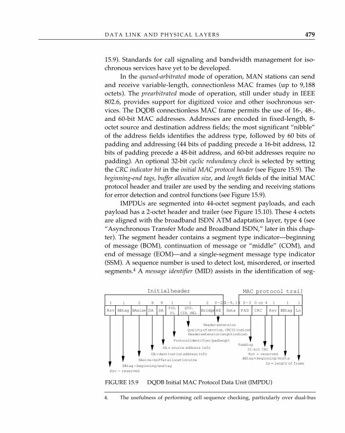
15.9). Standards for call signaling and bandwidth management for iso-chronous services have yet to be developed.
In the queued-arbitrated mode of operation, MAN stations can sendand receive variable-length, connectionless MAC frames (up to 9,188octets). The prearbitrated mode of operation, still under study in IEEE802.6, provides support for digitized voice and other isochronous ser-vices. The DQDB connectionless MAC frame permits the use of 16-, 48-,and 60-bit MAC addresses. Addresses are encoded in fixed-length, 8-octet source and destination address fields; the most significant “nibble”of the address fields identifies the address type, followed by 60 bits ofpadding and addressing (44 bits of padding precede a 16-bit address, 12bits of padding precede a 48-bit address, and 60-bit addresses require nopadding). An optional 32-bit cyclic redundancy check is selected by settingthe CRC indicator bit in the initial MAC protocol header (see Figure 15.9). Thebeginning-end tags, buffer allocation size, and length fields of the initial MACprotocol header and trailer are used by the sending and receiving stationsfor error detection and control functions (see Figure 15.9).
IMPDUs are segmented into 44-octet segment payloads, and eachpayload has a 2-octet header and trailer (see Figure 15.10). These 4 octetsare aligned with the broadband ISDN ATM adaptation layer, type 4 (see“Asynchronous Transfer Mode and Broadband ISDN,” later in this chap-ter). The segment header contains a segment type indicator—beginningof message (BOM), continuation of message or “middle” (COM), andend of message (EOM)—and a single-segment message type indicator(SSM). A sequence number is used to detect lost, misordered, or insertedsegments.4 A message identifier (MID) assists in the identification of seg-
D A T A L I N K A N D P H Y S I C A L L A Y E R S 479
FIGURE 15.9 DQDB Initial MAC Protocol Data Unit (IMPDU)
BEtag BAsize DA SA Bridge HE PAD CRCRsv Rsv BEtag Ln
1 1 2 8 1 1 2 0–20 0–3 0 or 4 1PID,
PL
QOS,
CIB, HEL
Rsv = reserved
BEtag = beginning/end tag
BAsize = buffer allocation size
DA = destination address info
SA = source address info
Protocol identifier/pad length
Quality of service, CRC32 indicatoHeader extension length indicato
Ln = length of frame
8
Data
1–9,18 1 1
Padding
Header extension
32-bit CRCRsv = reserved
BEtag = beginning/end tag
Initial header MAC protocol trail
4. The usefulness of performing cell sequence checking, particularly over dual-bus
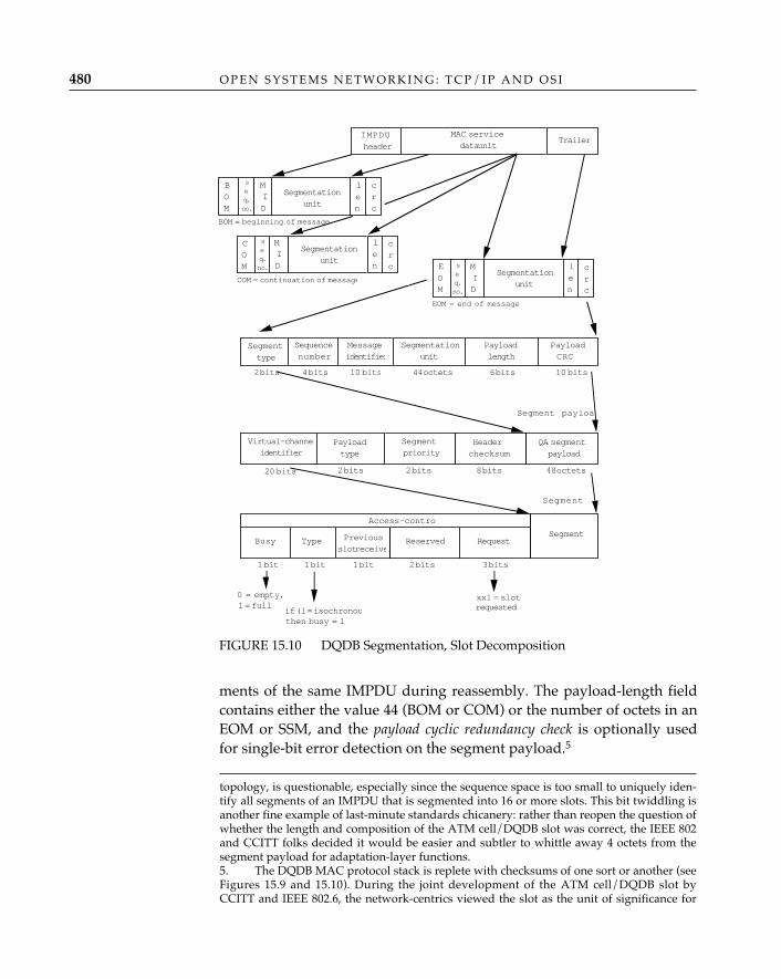
ments of the same IMPDU during reassembly. The payload-length fieldcontains either the value 44 (BOM or COM) or the number of octets in anEOM or SSM, and the payload cyclic redundancy check is optionally usedfor single-bit error detection on the segment payload.5
O P E N S Y S T E M S N E T W O R K I N G : T C P / I P A N D O S I480
topology, is questionable, especially since the sequence space is too small to uniquely iden-tify all segments of an IMPDU that is segmented into 16 or more slots. This bit twiddling is another fine example of last-minute standards chicanery: rather than reopen the question ofwhether the length and composition of the ATM cell/DQDB slot was correct, the IEEE 802and CCITT folks decided it would be easier and subtler to whittle away 4 octets from thesegment payload for adaptation-layer functions.5. The DQDB MAC protocol stack is replete with checksums of one sort or another (seeFigures 15.9 and 15.10). During the joint development of the ATM cell/DQDB slot byCCITT and IEEE 802.6, the network-centrics viewed the slot as the unit of significance for
FIGURE 15.10 DQDB Segmentation, Slot Decomposition
Segment payloa
Virtual-channelidentifier
Payloadtype
Segmentpriority
Headerchecksum
20 bits 2 bits 2 bits 8 bits
QA segmentpayload
48 octets
Segmenttype
Sequencenumber
Messageidentifier
Payloadlength
PayloadCRC
4 bits 10 bits 44 octets 6 bits 10 bits
Segmentationunit
2 bits
0 = empty,1 = full
if (1 = isochronouthen busy = 1
xx1 = slotrequested
1 bit 1 bit1 bit 2 bits 3 bits
Busy Type Previousslot receive
Reserved Request
Access-contro
Segment
Segment
IMPDUheader
MAC servicedata unit
Trailer
BOM
MID
Segmentationunit
len
crc
COM
BOM = beginning of message
COM = continuation of message
EOM = end of message
seq.no.
OM
eq# Unit
ID
Segmentationunit
seq.no.
MID
len
crc
OM
Segmentationunit
seq.no.
MID
len
crc
EOM
Connectionless MAC stations operate in what is called queued-arbi-trated (QA) mode. Heads of bus A and B continuously generate/forward53-octet queued-arbitrated slots on their respective buses, composed of a1-octet access control field (ACF) and a 52-octet payload (see Figure 15.10).The operation of the distributed queue access protocol is predicated on thevalues of two fields of the ACF: the busy bit indicates whether the slot isempty (available) or full (taken). The request bits indicate whether slotshave been queued for access (i.e., that a station has requested a slot).Each station maintains two request counters, one for each bus (logically,one for each direction of information flow). A station in the idle state(i.e., one with nothing to send) decrements the request counter for eachempty slot it sees on bus A and increments the same request counter by 1for each request bit set on bus B; i.e., it constantly checks how many slotshave been queued on bus A. In so doing, a station establishes its positionin the distributed queue, relative to other stations wishing to send on busA (a similar computation occurs simultaneously for bus B).
When a station wishes to send on bus A, it writes a request on busA; i.e., it writes a binary 1 to the request bit in the access-control field ofthe first slot that has not already been used by downstream stations torequest slots. The station copies the current value of the request counterfrom bus B into a countdown counter, then decrements the countdowncounter each time an empty slot passes by on bus A; i.e., a station waitsuntil all the stations that have queued requests to send on bus A ahead ofit have satisfied their requests (sort of like children in a classroom raisingtheir hands and waiting their turn). When the countdown counter reaches0, the station copies the next empty slot from bus A, fills the payloadwith user data, marks the slot busy, and writes it back to bus A. The pro-cess is the same if a station wishes to send a slot on bus B; here, the sta-tion queues a request on bus B, copies the current value of the requestcounter from bus A into the countdown counter, and waits until all thestations that have queued requests to send on bus B ahead of it have sat-isfied their requests.
The DQDB MAN MAC protocol was developed in a physical-trans-mission-facilities-independent fashion; i.e., the MAN can operate over avariety of physical transmission systems, including those currently used
D A T A L I N K A N D P H Y S I C A L L A Y E R S 481
all broadband services and insisted that error detection and recovery be performed on acell-by-cell basis. Host-centrics pointed to the IEEE 802.1a LAN architecture standard andclaimed that to be consistent with all the MACs that preceded IEEE 802.6, error detection—in the form of a 32-bit CRC—should be performed on the initial MAC protocol data unit.Who won? Everybody . . . sort of. There are optional error-detection functions for the entireIMPDU and optional error-correction functions for the slot header.
by telephony providers in the United States, throughout Europe, andAsia, as well as the emerging SONET transmission system, describedlater in this chapter. Borrowing (perhaps subliminally) from the princi-ples of convergence described in the Internal Organization of the NetworkLayer (see Chapter 13), physical layer convergence procedures (PLCPs) havebeen defined to describe how to map DQDB slots onto physical-layerframing provided by a variety of standard telephony transmission sys-tems (Brandwein, Cox, and Dahl 1990). PLCPs enable the DQDB MANMAC to operate over existing telephony digital transmission hierarchiesat rates of 1.544 Mbps (DS1) and 44.736 Mbps (DS3) in North Americaand at rates of 2.048 Mbps (E1), 34.368 Mbps (E3), and 139.264 Mbps (E4)in Europe and Asia, as well as over SONET (discussed later in this chap-ter). This, combined with the fact that the length and encoding of DQDBsegments is intentionally aligned with the ATM “cell” of the broadbandISDN under study in CCITT, makes IEEE 802.6 attractive for a public net-work service. Two such services are currently under trial and earlydeployment in the United States and several European countries:switched multimegabit data service (SMDS) and the European Telecom-munications Standards Institute’s MAN project (ETSI MAN).
Fast Packet Services and TechnologiesThe term “fast packet” has emerged from the telecommunications indus-ry as a way to collectively refer to transmission technologies that may beused in wide area network as well as local area network and campus con-figurations. These technologies may be operated over existing telecom-munications digital transmission facilities to provide public data net-working services that offer higher bandwidth and lower delay character-istics than their “narrowband” predecessors, ISDN and X.25. In the fol-lowing sections we describe the most prominent of these emerging“broadband” services—SMDS and its European cousin, ETSI MAN,frame relay, and ATM—and a relatively new and promising fiber-optictransport system, SONET.
SMDS is a public, packet-switched datagram service. The service is oftendescribed as “LAN-analogous” (Bellcore Technical Requirement TR-TSV-000772 1991), meaning that the features of the public service—high band-width, low delay, large packet sizes, multicasting, address screening/fil-tering—emulate characteristics of LANs. The interface protocol to thepublic network (SMDS interface protocol, or SIP) is based on the IEEE
O P E N S Y S T E M S N E T W O R K I N G : T C P / I P A N D O S I482
SwitchedMultimegabitData Service
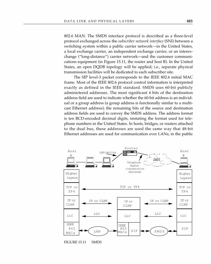
802.6 MAN. The SMDS interface protocol is described as a three-levelprotocol exchanged across the subscriber network interface (SNI) between aswitching system within a public carrier network—in the United States,a local exchange carrier, an independent exchange carrier, or an interex-change (“long-distance”) carrier network—and the customer communi-cations equipment (in Figure 15.11, the router and host B). In the UnitedStates, an open DQDB topology will be applied; i.e., separate physicaltransmission facilities will be dedicated to each subscriber site.
The SIP level-3 packet corresponds to the IEEE 802.6 initial MACframe. Most of the IEEE 802.6 protocol control information is interpretedexactly as defined in the IEEE standard. SMDS uses 60-bit publiclyadministered addresses. The most significant 4 bits of the destinationaddress field are used to indicate whether the 60-bit address is an individ-ual or a group address (a group address is functionally similar to a multi-cast Ethernet address); the remaining bits of the source and destinationaddress fields are used to convey the SMDS address. The address formatis ten BCD-encoded decimal digits, imitating the format used for tele-phone numbers in the United States. In hosts, bridges, or routers attachedto the dual bus, these addresses are used the same way that 48-bitEthernet addresses are used for communication over LANs; in the public
D A T A L I N K A N D P H Y S I C A L L A Y E R S 483
FIGURE 15.11 SMDS
IP orCLNP
LLC
IEEE802
MACs
TCP orTP4
Higherlayers
SIPSIPLAN SMDS
TCP or TP4
IP or CLNP IP or CLNP
LLC LLC
IP orCLNP
IEEE802
MACs
LLC
Higherlayers
TCP orTP4
IP orCLNP
LLC
HostA
HostB
RouterLAN cabling
Telephonedigital
transmissionfacilities
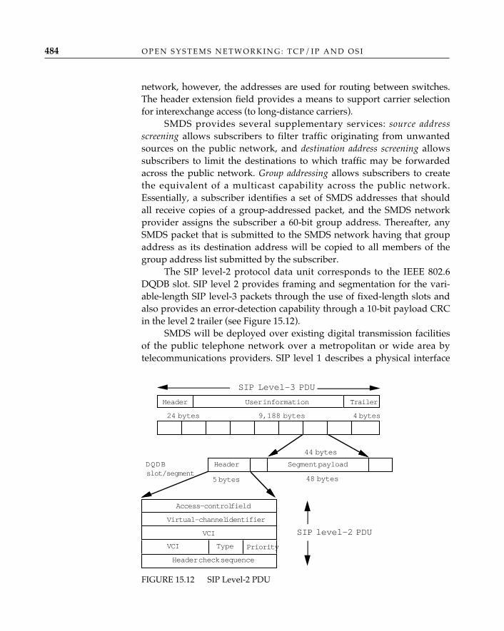
network, however, the addresses are used for routing between switches.The header extension field provides a means to support carrier selectionfor interexchange access (to long-distance carriers).
SMDS provides several supplementary services: source addressscreening allows subscribers to filter traffic originating from unwantedsources on the public network, and destination address screening allowssubscribers to limit the destinations to which traffic may be forwardedacross the public network. Group addressing allows subscribers to createthe equivalent of a multicast capability across the public network.Essentially, a subscriber identifies a set of SMDS addresses that shouldall receive copies of a group-addressed packet, and the SMDS networkprovider assigns the subscriber a 60-bit group address. Thereafter, anySMDS packet that is submitted to the SMDS network having that groupaddress as its destination address will be copied to all members of thegroup address list submitted by the subscriber.
The SIP level-2 protocol data unit corresponds to the IEEE 802.6DQDB slot. SIP level 2 provides framing and segmentation for the vari-able-length SIP level-3 packets through the use of fixed-length slots andalso provides an error-detection capability through a 10-bit payload CRCin the level 2 trailer (see Figure 15.12).
SMDS will be deployed over existing digital transmission facilitiesof the public telephone network over a metropolitan or wide area bytelecommunications providers. SIP level 1 describes a physical interface
O P E N S Y S T E M S N E T W O R K I N G : T C P / I P A N D O S I484
FIGURE 15.12 SIP Level-2 PDU
Virtual-channel identifier
48 bytes5 bytes
Access-control field
VCI Type Priority
Header check sequence
Header Segment payload
VCI
User informationHeader Trailer
24 bytes 9,188 bytes 4 bytes
DQDBslot/segment
44 bytes
SIP level-2 PDU
SIP Level-3 PDU
to the digital transmission network. Currently, two access rates are de-fined. A PLCP is defined for DS3, which provides a transfer rate of44.736 Mbps, and for DS1, which provides a transfer rate of 1.544 Mbps.The DS1 physical interface uses the extended superframe format (ESF).SMDS is described in a series of Bellcore Technical Requirements (TR-TSV-000772 1991; TR-TSV-000773 1991).
There will be a number of subscribers who may want to benefitfrom the low latency offered by the DS3 access for bursty data applica-tions but whose sustained information rates are expected to be muchlower than 45 megabits per second. Access classes allow customers to sub-scribe to what are essentially “fractions” of bandwidth for both burstyand sustained data transmission. The mechanism is straightforward. Acustomer selects an access class (separate access class tariffs are expectedfor sustained information rates of approximately 4, 10, 16, and 25 Mbps,accompanied by maximum burst rates of approximately 10, 13, 18, and34 Mbps, respectively). A credit manager monitors the rate at which SIPlevel-2 protocol data units are sent to the network. If the rate at whichthe subscriber sends SIP level-2 protocol data units into the networkexceeds either the subscribed-to sustained information rate or the maximumburst rate, the network provider will discard the excess (see BellcoreTechnical Requirement TR-TSV-000772 [1991] for more details on this“leaky bucket” or credit manager algorithm).
SMDS will be used primarily for local area network interconnec-tion. The unusual (unprecedented) combination of local area networkcharacteristics and telephony-style numbering in SMDS makes the ser-vice suitable for a number of interenterprise (multiorganizational) aswell as intraenterprise applications (this is touted as “any-to-any com-munication”). Early trial and field experience has demonstrated thatSMDS can be used as a “gathering net” for commercial IP networks (itmay also be used as part of the backbone network). In this scenario, thecommercial IP provider subscribes to “fat” DS3 SMDS pipes and recom-mends SMDS access at DS1 rates to its customers. The DS3 SMDS accessprovides an aggregation point for the IP provider and reduces the num-ber of interfaces the IP provider must manage and pay for.
SMDS can also be used by disaster recovery service providers (peo-ple who provide data center redundancy—i.e., exact duplicates of an or-ganization’s data-processing environment and database) to simplify andreduce the cost of cutover procedures following a catastrophic failure. Inthis scenario, the disaster recovery service provider recommends SMDSfor wide area service; if an earthquake destroys a company’s data center,cut-over to the duplicate data center is a matter of “entering a different
D A T A L I N K A N D P H Y S I C A L L A Y E R S 485
telephone number” in routing tables across the company’s internetwork.This is considerably simpler and faster than reprovisioning private linesand virtual-circuit services and cheaper than subscribing to additionalprivate lines to the disaster recovery service provider.
SMDS makes it convenient and economical for organizations tohave many temporary communications partners (commercial IP pro-viders do this as well, but incredible as it may seem, there are folks whodo not use them). For example, medical centers may routinely distributeX-ray, magnetic resonance, and positron tomography images to affiliatedmedical schools and attending physicians, but on occasion, they maywish to distribute them to specialist and other medical centers. In thesecircumstances, SMDS may offer an attractive alternative to constructingand operating a private network.
To accommodate those enterprises that want SMDS but cannot jus-tify the cost of DS1 access to all locations, frame-based access at 56 and 64Kbps—in many instances, on frame-relay interfaces—will be offered bylocal and interexchange carriers. In these configurations, the SMDS level-3 packet is encapsulated in an HDLC frame rather than segmented (atsuch low rates, the packetization into IEEE 802.6 slots is impractical).SMDS will eventually be offered over SONET interfaces (discussed laterin this chapter) and, as broadband switching is introduced into publicnetworks, over ATM as well.
Like SMDS in the United States, the ETSI MAN responds to the Euro-pean consumer demand for multimegabit communication services. Anenabling vehicle for broadband ISDN, ETSI MAN is slightly more ambi-tious than SMDS, encompassing
• A “packet-oriented” MAC service of ISO 8802 LANs, suitable forbursty data communications
• A connection-oriented isochronous service, suitable for voice andvideo applications
• A connection-oriented, nonisochronous service alternative for datacommunications
Like SMDS, ETSI MAN applies the DQDB MAN MAC protocol forthe connectionless MAC service. Because the regulatory environment inmany parts of Europe differs from that in the United States, single- ormultisubscriber access facilities may be provided, and both open andlooped topologies are anticipated. Two forms of interface are describedin the ETSI MAN architecture (“ETSI Metropolitan Area Network” 1991).The user MAN interface is similar to SMDS; the public network provides a
O P E N S Y S T E M S N E T W O R K I N G : T C P / I P A N D O S I486
ETSI MAN
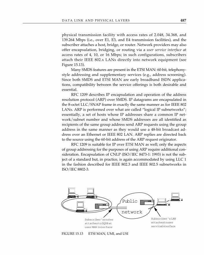
physical transmission facility with access rates of 2.048, 34.368, and139.264 Mbps (i.e., over E1, E3, and E4 transmission facilities), and thesubscriber attaches a host, bridge, or router. Network providers may alsooffer encapsulation, bridging, or routing via a user service interface ataccess rates of 4, 10, or 16 Mbps; in such configurations, subscribersattach their IEEE 802.x LANs directly into network equipment (seeFigure 15.13).
Many SMDS features are present in the ETSI MAN: 60-bit, telephony-style addressing and supplementary services (e.g., address screening).Since both SMDS and ETSI MAN are early broadband ISDN applica-tions, compatibility between the service offerings is both desirable andessential.
RFC 1209 describes IP encapsulation and operation of the addressresolution protocol (ARP) over SMDS. IP datagrams are encapsulated inthe 8-octet LLC/SNAP frame in exactly the same manner as for IEEE 802LANs. ARP is performed over what are called “logical IP subnetworks”;essentially, a set of hosts whose IP addresses share a common IP net-work/subnet number and whose SMDS addresses are all identified asrecipients of the same group address send ARP requests using the groupaddress in the same manner as they would use a 48-bit broadcast ad-dress over an Ethernet or IEEE 802 LAN. ARP replies are directed backto the source using the 60-bit address of the ARP request originator.
RFC 1209 is suitable for IP over ETSI MAN as well; only the aspectsof group addressing for the purposes of using ARP require additional con-sideration. Encapsulation of CNLP (ISO/IEC 8473-1: 1993) is not the sub-ject of a standard but, in practice, is again accommodated by using LLC 1in the fashion described for IEEE 802.3 and IEEE 802.5 subnetworks inISO/IEC 8802-3.
D A T A L I N K A N D P H Y S I C A L L A Y E R S 487
FIGURE 15.13 ETSI MAN, UMI, and USI
Public
Subscriber's LANattaches to userservice interface
Subscriber's routerattaches to DQDB atuser MAN interface
network
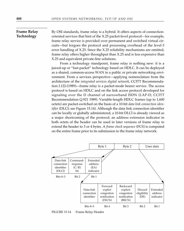
Bits 8–3 Bit 2 Bit 1
By OSI standards, frame relay is a hybrid. It offers aspects of connection-oriented services that hint of the X.25 packet-level protocol—for example,frame relay service is provided over permanent and switched virtual cir-cuits—but forgoes the protocol and processing overhead of the level-3error handling of X.25. Since the X.25 reliability mechanisms are omitted,frame relay offers higher throughput than X.25 and is less expensive thanX.25 and equivalent private-line solutions.
From a technology standpoint, frame relay is nothing new: it is ajuiced-up or “fast-packet” technology based on HDLC. It can be deployedas a shared, common-access WAN in a public or private networking envi-ronment. From a services perspective—applying nomenclature from thearchitecture of the integrated services digital network, CCITT Recommenda-tion I.122-(1989)—frame relay is a packet-mode bearer service. The accessprotocol is based on HDLC and on the link access protocol developed forsignaling over the D channel of narrowband ISDN (LAP-D; CCITTRecommendation Q.921 1989). Variable-length HDLC frames (up to 1,600octets) are packet-switched on the basis of a 10-bit data link connection iden-tifier (DLCI; see Figure 15.14). Although the data link connection identifiercan be locally or globally administered, a 10-bit DLCI is already viewed asa major shortcoming of the protocol; an address extension indicator inboth octets of the header can be used in later versions of frame relay toextend the header to 3 or 4 bytes. A frame check sequence (FCS) is computedon the entire frame prior to its submission to the frame relay network.
O P E N S Y S T E M S N E T W O R K I N G : T C P / I P A N D O S I488
Frame RelayTechnology
FIGURE 15.14 Frame Relay Header
Byte 1 Byte 2 User data
Data-link Command- Extendedconnection response addressidentifier (C/R) (EA)(DLCI) bit indicator
Forward BackwardData-link explict explicit Discard Extended
connection congestion congestion eligibility addressidentifier notification notification (DE) indicator
(FECN) (BECN)
Bits 8–5 Bit 4 Bit 3 Bit 2 Bit 1
Network (switch) processing of incoming frames is as follows. Ifthe frame check sequence check is successful, the data link connectionidentifier is used as an index into a table of trunks over which frames areforwarded (relayed) to (toward) their destinations. If the FCS check fails,the frame is discarded. At the ingress point, the DLCI encoded in theincoming frame indicates the destination; however, the DLCI is modifiedby the network prior to transmission across the egress link so that theDLCI in the outgoing frame contains the source (the switch thus recom-putes or adjusts the FCS as part of the processing of each frame).
Internal to frame relay networks, frame relay providers apply theconcepts of statistical multiplexing: every user is not expected to use all ofthe bandwidth subscribed to every minute of every day, so resources(switching equipment, trunk lines between switches) are allocated tohandle what is determined to be a reasonable load under normal condi-tions. As with highways, anticipated traffic loads can be exceeded, andcongestion can occur. In a frame relay network, congestion is alleviatedby discarding frames. Frame relay offers explicit congestion notification(ECN) mechanisms that are similar to that of OSI CLNP (see Chapter 13),but bidirectionally: forward and backward indications—FECNs andBECNs —are defined. Computers attached to frame relay circuits arethus notified that the network is discarding packets.
Frame relay provides another mechanism to maintain fairnessamong multiple senders. A discard eligibility indicator can be set by asender or the network to indicate that certain frames are sacrificial lambs;i.e., if frames must be discarded, throw away the frames that have theDE flag set.
In theory, the DE bit may be used to guarantee some level of ser-vice (especially, throughput) to individual data link connections; i.e., theDE bit might be set in all frames of a given data link connection, but notset in the frames sent over a second data link connection, effectivelyassigning a higher priority of service to the users of the second data linkconnection. Under an arrangement such as this, an IP or CLNP networkadministrator can bias much of the committed information rate negotiatedbetween the subscriber and network provider toward the (privileged)users of one data link connection. (Committed information rate is a sub-scription time parameter used by public frame relay providers that is anestimate of the user’s “normal” throughput needs and a measure of theamount of data the public network promises to deliver.)
The “features” of congestion notification and discard eligibilityare often promoted imprudently in frame relay marketing. As
✧AHA✧
D A T A L I N K A N D P H Y S I C A L L A Y E R S 489
an indicator in an end-to-end datagram network-layer protocol like CLNP, acongestion-experienced notification can be conveyed to the transport layer,where mechanisms exist to reduce the rate of traffic introduced into a network bya source end system. Beyond the obvious marketing value of being able to say,“We notify you of congestion,” the usefulness of these indicators in a data linkprotocol is questionable. Unless additional mechanisms are introduced in thenetwork layer protocol operating over a frame relay service to propagate conges-tion-status information of the frame relay link back to all sources—for example,mapping the value of a BECN/FECN received across a frame relay link into thecongestion-experienced bit of the CLNP header—the notification is an annoyingno-op. (Well, not quite; routers that have SNMP agents can now count thenumber of FECNs and BECNs received, so one at least knows whether the framerelay network is overworked). And unless transport protocol entities operatingat traffic sources “behave” and actually slow down the rate at which they intro-duce traffic, FECNs and BECNs have absolutely no effect on the rate of packetflow into the frame relay network. Finally, in multiprotocol environments (OSI,TCP/IP, etc.), relying on single-bit congestion notification can be dangerous:unless all network layer protocols propagate congestion notices, and all end sys-tem transport implementations react to this information by changing their ratesof transmission uniformly, it is quite possible that those end systems that behavewell will be penalized (they will slow down) and those that ignore the informa-tion will benefit (since others have slowed down, they may be able to continue attheir present rate without penalty).
It’s easy to sum up the “truthful” aspects of advertisement regarding dis-card eligibility: discard eligibility relies on cooperation on the part of all senders,all of whom will responsibly identify which of their data aren’t important.
Both CNLP and IP implementations will treat frame relay as apoint-to-point network. RFC 1294 describes IP encapsulation and opera-tion over frame relay as part of a multiprotocol identification and encap-sulation scheme. Each protocol that is to be transmitted across a framerelay circuit is identified using a 1-octet network layer protocol identifier(see Chapter 13), which must be the first octet encoded in the frame relayframe. Values assigned by ISO and CCITT distinguish among the OSInetwork layer protocols, and code points in the NLPID are also used toidentify the encapsulated protocol as IP and the IEEE 802.1 SNAP. TheNLPID value for SNAP is used for bridging purposes and also to indicatethat the ethertype value is to be used to distinguish among the protocolsthat do not have an NLPID assigned to them6 (see Assigned Numbers, RFC
O P E N S Y S T E M S N E T W O R K I N G : T C P / I P A N D O S I490
6. It seems that history is forever repeating itself. Standards makers, failing to heed the
1340). Encapsulation of CNLP over frame relay is not the subject of astandard, but in multiprotocol environments, it is expected that RFC1294 will be applied. RFC 1294 also prescribes maximum packet sizes forframe relay networks and describes a means of negotiating a maximumframe size, a retransmission timer, and a maximum number of outstand-ing information frames, using HDLC exchange identification (XID)frames. Some frame relay networks (the switches, actually) support amaximum frame size of only 262 octets; since this is much smaller thanthe default maximum IP segment size of 576 octets, RFC 1294 defines a“convergence protocol” that must be used to segment IP packets beforethey are forwarded across such networks.
Address resolution over frame relay networks is a matter of associ-ating a data link connection identifier with the IP address of a station on“the other side” of a permanent virtual circuit. The inverse address resolu-tion protocol (INARP; RFC 1293) proceeds as follows. An IP station per-forms address resolution by (1) constructing an ARP request packet, (2)encapsulating the packet in a frame relay packet, and (3) sending itdirectly to the target DLCI (note that there is no notion of broadcast orgroup addressing of ARP requests over frame relay). The INARP requestpacket is essentially the same format as other ARP requests: the source IPaddress is provided, and the target IP address field is 0-filled; however, inthe case of frame relay, the requesting station inserts DLCIs rather thanconventional 48-bit LAN addresses in the source and target hardwareaddress fields. Upon receiving an INARP request, the called, or target,station will typically place the requester’s {IP address, DLCI} mappinginto its ARP cache. The target station then composes an INARP replyusing the source DLCI and IP addresses from the INARP request as thetarget addresses for the INARP reply and using its own DLCI and IPaddresses to populate the source hardware and network protocol ad-dresses, respectively. When the requesting IP station receives the INARPreply, it uses the {IP address, DLCI} address information from the INARPreply to complete its ARP cache.
Like SMDS, frame relay will be used primarily for local area net-work interconnection. It is a direct and cheap replacement for privatelines. When switched virtual circuits are offered, frame relay will pro-vide the virtual-circuit equivalent of any-to-any connectivity; until then,it is best suited for intraenterprise topologies.
D A T A L I N K A N D P H Y S I C A L L A Y E R S 491
lessons from the service access point debacle of the logical link control, also made the OSINLPID a single-octet field and may again find themselves with insufficient code points toidentify all the protocols that might be identified using the NLPID demultiplexing scheme.

Frame relay allows companies to supplant existing private lineswith statistically multiplexed services at a lower cost per access line. Thisis attractive because it gives subscribers some interesting cost-perfor-mance trade-offs:
• Replace the existing private-line topology with correspondingframe relay permanent virtual circuits and reduce monthly commu-nications costs. In this scenario, a network administrator wouldreplace the private topology with permanent virtual circuits form-ing an identical virtual topology.
• Replace existing private lines with frame relay permanent virtualcircuits and use the savings to enrich the topology by adding per-manent virtual circuits. Frame relay tariffs often have an access-con-nection component, an information-transfer (switching) component,and per permanent virtual circuit charges. The permanent virtualcircuit charges are relatively low, so some or all of the savingsaccrued by converting to a switched service could be used to addpermanent virtual circuits between routers, especially betweenrouters where no private lines existed. They would improve overallnetwork performance by eliminating one hop.
• Replace existing private lines with frame relay permanent virtualcircuits and use the savings to enrich the topology by subscribing tohigher-rate access connections. The reduction in monthly communi-cations costs may be significant enough over a given topology tojustify the use of a DS1 facility (or fraction thereof) rather than a 56Kbps or 64 Kbps access connection.
Like SMDS, frame relay services are likely to be offered over in-creasingly higher-bandwidth access connections. If there is a market pullfor it, 45 Mbps frame relay access will undoubtedly be offered.
There are currently two schools of thought regarding the evolutionor migration of frame relay services to a broadband ISDN environment.School 1 recommends that the relatively straightforward process of map-ping data from one virtual circuit onto another be used. Here, an inter-working unit—a data link service bridge—will maintain a logical relation-ship between frame relay data link connection identifiers and broadbandISDN virtual circuit identifiers and will forward encapsulated data (e.g.,IP or CLNP packets) between the two networks. School 2 recommendsthat the frame relay bearer service operate on the asynchronous transfermode platform that supports all broadband ISDN services (see “Asynch-ronous Transfer Mode and Broadband ISDN,” later in this chapter). Here,frame relay frames operate over asynchronous transfer mode and even-
O P E N S Y S T E M S N E T W O R K I N G : T C P / I P A N D O S I492
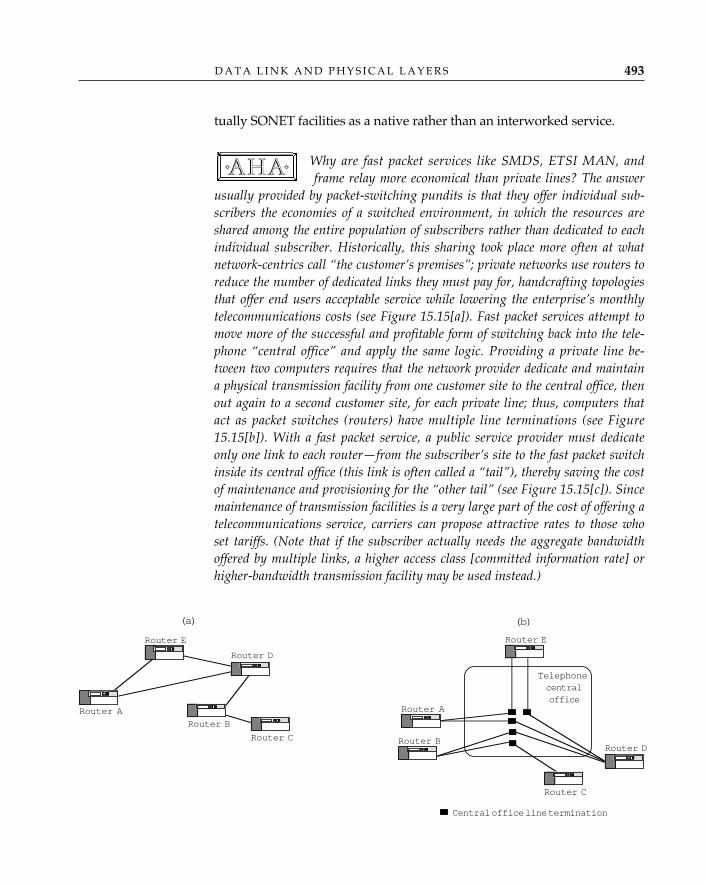
tually SONET facilities as a native rather than an interworked service.
Why are fast packet services like SMDS, ETSI MAN, andframe relay more economical than private lines? The answer
usually provided by packet-switching pundits is that they offer individual sub-scribers the economies of a switched environment, in which the resources areshared among the entire population of subscribers rather than dedicated to eachindividual subscriber. Historically, this sharing took place more often at whatnetwork-centrics call “the customer’s premises”; private networks use routers toreduce the number of dedicated links they must pay for, handcrafting topologiesthat offer end users acceptable service while lowering the enterprise’s monthlytelecommunications costs (see Figure 15.15[a]). Fast packet services attempt tomove more of the successful and profitable form of switching back into the tele-phone “central office” and apply the same logic. Providing a private line be-tween two computers requires that the network provider dedicate and maintaina physical transmission facility from one customer site to the central office, thenout again to a second customer site, for each private line; thus, computers thatact as packet switches (routers) have multiple line terminations (see Figure15.15[b]). With a fast packet service, a public service provider must dedicateonly one link to each router—from the subscriber’s site to the fast packet switchinside its central office (this link is often called a “tail”), thereby saving the costof maintenance and provisioning for the “other tail” (see Figure 15.15[c]). Sincemaintenance of transmission facilities is a very large part of the cost of offering atelecommunications service, carriers can propose attractive rates to those whoset tariffs. (Note that if the subscriber actually needs the aggregate bandwidthoffered by multiple links, a higher access class [committed information rate] orhigher-bandwidth transmission facility may be used instead.)
✧AHA✧
D A T A L I N K A N D P H Y S I C A L L A Y E R S 493
(a)
Router B
Router C
Router D
Router E
Router A
(b)
Telephonecentraloffice
Router A
Router E
Router DRouter B
Router C
Central office line termination
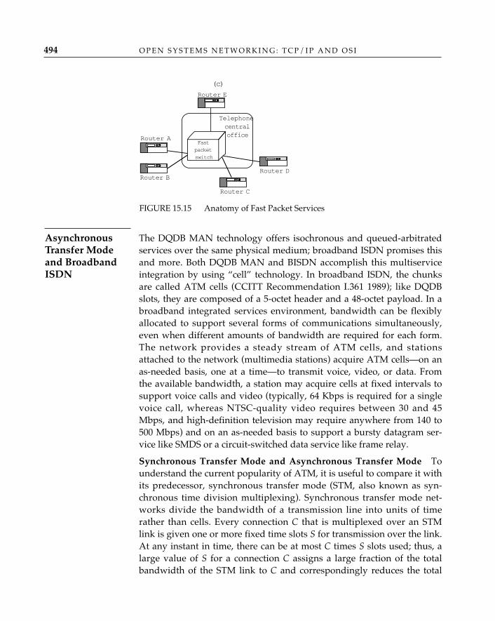
The DQDB MAN technology offers isochronous and queued-arbitratedservices over the same physical medium; broadband ISDN promises thisand more. Both DQDB MAN and BISDN accomplish this multiserviceintegration by using “cell” technology. In broadband ISDN, the chunksare called ATM cells (CCITT Recommendation I.361 1989); like DQDBslots, they are composed of a 5-octet header and a 48-octet payload. In abroadband integrated services environment, bandwidth can be flexiblyallocated to support several forms of communications simultaneously,even when different amounts of bandwidth are required for each form.The network provides a steady stream of ATM cells, and stationsattached to the network (multimedia stations) acquire ATM cells—on anas-needed basis, one at a time—to transmit voice, video, or data. Fromthe available bandwidth, a station may acquire cells at fixed intervals tosupport voice calls and video (typically, 64 Kbps is required for a singlevoice call, whereas NTSC-quality video requires between 30 and 45Mbps, and high-definition television may require anywhere from 140 to500 Mbps) and on an as-needed basis to support a bursty datagram ser-vice like SMDS or a circuit-switched data service like frame relay.
Synchronous Transfer Mode and Asynchronous Transfer Mode—Tounderstand the current popularity of ATM, it is useful to compare it withits predecessor, synchronous transfer mode (STM, also known as syn-chronous time division multiplexing). Synchronous transfer mode net-works divide the bandwidth of a transmission line into units of timerather than cells. Every connection C that is multiplexed over an STMlink is given one or more fixed time slots S for transmission over the link.At any instant in time, there can be at most C times S slots used; thus, alarge value of S for a connection C assigns a large fraction of the totalbandwidth of the STM link to C and correspondingly reduces the total
O P E N S Y S T E M S N E T W O R K I N G : T C P / I P A N D O S I494
(c)
TelephonecentralofficeRouter A
Router E
Router DRouter B
Router C
Fastpacketswitch
FIGURE 15.15 Anatomy of Fast Packet Services
AsynchronousTransfer Modeand BroadbandISDN
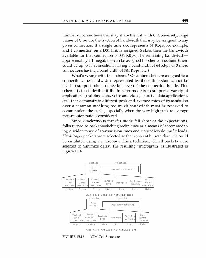
number of connections that may share the link with C. Conversely, largevalues of C reduce the fraction of bandwidth that may be assigned to anygiven connection. If a single time slot represents 64 Kbps, for example,and 1 connection on a DS1 link is assigned 6 slots, then the bandwidthavailable for that connection is 384 KBps. The remaining bandwidth—approximately 1.1 megabits—can be assigned to other connections (therecould be up to 17 connections having a bandwidth of 64 Kbps or 3 moreconnections having a bandwidth of 384 Kbps, etc.).
What’s wrong with this scheme? Once time slots are assigned to aconnection, the bandwidth represented by those time slots cannot beused to support other connections even if the connection is idle. Thisscheme is too inflexible if the transfer mode is to support a variety ofapplications (real-time data, voice and video, “bursty” data applications,etc.) that demonstrate different peak and average rates of transmissionover a common medium; too much bandwidth must be reserved toaccommodate the peaks, especially when the very high peak-to-averagetransmission ratio is considered.
Since synchronous transfer mode fell short of the expectations,folks turned to packet-switching techniques as a means of accommodat-ing a wider range of transmission rates and unpredictable traffic loads.Fixed-length packets were selected so that constant bit rate channels couldbe emulated using a packet-switching technique. Small packets wereselected to minimize delay. The resulting “microgram” is illustrated inFigure 15.16.
D A T A L I N K A N D P H Y S I C A L L A Y E R S 495
Genericflowcontrol
Virtualpath
identifier
Virtualchannelidentifier
Payloadtype Reserved
Cell-losspriority
Cellheader
checksum
4 bits 8 bits 16 bits 2 bits 1 bit 1 bit 8 bits
ATM cell—User-to-network inte
5 octets 48 octets
Cellheader Payload (user data)
5 octets 48 octets
Cellheader Payload (user data)
ReservedCell-losspriority
Virtualchannelidentifier
Payloadtype
ATM cell—Network-to-network int
12 bits 16 bits 2 bits 8 bits1 bit1 bit
Virtualpath
identifier
Cellheader
checksum
FIGURE 15.16 ATM Cell Structure
ATM Cell Structure—Actually, there are two forms of the microgram:the cell submitted by and delivered to customer communications equip-ment (i.e., across the user-to-network interface [UNI] and the cell that istransferred betwen ATM networks (i.e., across a network-to-network inter-face [NNI]). The initial field of the ATM user-to-network interface cell is ageneric flow indicator (4 bits), which will be used for end-to-end flow con-trol between ATM stations. A virtual-path identifier (8 bits) identifies thepath between a source and destination ATM station pair, and a virtual-channel identifier (16 bits) defines a connection within the virtual path. Apayload type (3 bits) identifies the contents of the payload (currently onlyone value, 0, for user information) and provides congestion notification.A cell loss priority (1 bit) is like the discard eligibility bit in frame relay. An8-bit cell header checksum can be used to detect and in some cases correcterrors in the cell header. The ATM network-to-network interface cell isidentical in all but one respect to the ATM user-to-network interface cell:the UNI generic flow indicator is not present in the NNI cell and the vir-tual-path identifier is extended an additional 4 bits.
To accommodate voice and perhaps real-time video withoutecho effects, the current wisdom is that fixed (or predictable)
delay between cells/slots must be maintained. After considerable debate overpacketization delay and packet length, CCITT, T1, and IEEE 802.6 converged ona chunk/cell/slot length of 53 octets (5 for the header, 48 for the payload). Thenumber 48 is notable because it is a fine example of the standards process inaction. There is little technological substance in the decision to use 48 octets; it isa compromise between the 64-octet payload originally specified in the DQDBMAN standard and the 32-octet payload preferred by CCITT and T1. “I like 32,you like 64. Let’s meet somewhere in the middle . . .”
ATM Adaptation Layers—Although they will be multiplexed/inter-leaved over the same cell/slot fabric, voice, video, and data services willuse fixed-length cells in different ways; for example, a data service likeSMDS could be implemented over a broadband ISDN platform andrequires an IMPDU-to-cell mapping and SAR functions similar to thoseprovided in the IEEE 802.6 architecture. The functions and protocols re-quired to provide these services to the MAC layer (and similar services forvoice and video) are placed at what is called the BISDN ATM adaptationlayer (AAL; CCITT Recommendation I.362-1989), and there are several(CCITT Recommendation I.363-1989): AAL1 is provided for voice, AAL2for video, AAL3 for mapping frame relay onto a cell fabric, and AAL4 isnearly identical to the IEEE 802.6 DQDB (see Figures 15.8 and 15.10). A
✧AHA✧
O P E N S Y S T E M S N E T W O R K I N G : T C P / I P A N D O S I496
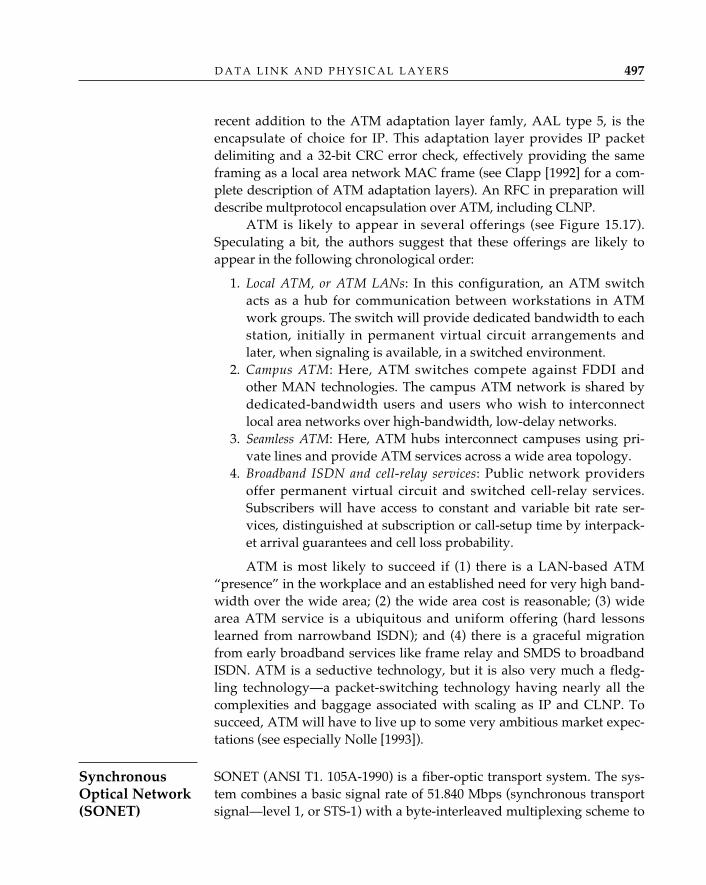
recent addition to the ATM adaptation layer famly, AAL type 5, is theencapsulate of choice for IP. This adaptation layer provides IP packetdelimiting and a 32-bit CRC error check, effectively providing the sameframing as a local area network MAC frame (see Clapp [1992] for a com-plete description of ATM adaptation layers). An RFC in preparation willdescribe multprotocol encapsulation over ATM, including CLNP.
ATM is likely to appear in several offerings (see Figure 15.17).Speculating a bit, the authors suggest that these offerings are likely toappear in the following chronological order:
1. Local ATM, or ATM LANs: In this configuration, an ATM switchacts as a hub for communication between workstations in ATMwork groups. The switch will provide dedicated bandwidth to eachstation, initially in permanent virtual circuit arrangements andlater, when signaling is available, in a switched environment.
2. Campus ATM: Here, ATM switches compete against FDDI andother MAN technologies. The campus ATM network is shared bydedicated-bandwidth users and users who wish to interconnectlocal area networks over high-bandwidth, low-delay networks.
3. Seamless ATM: Here, ATM hubs interconnect campuses using pri-vate lines and provide ATM services across a wide area topology.
4. Broadband ISDN and cell-relay services: Public network providersoffer permanent virtual circuit and switched cell-relay services.Subscribers will have access to constant and variable bit rate ser-vices, distinguished at subscription or call-setup time by interpack-et arrival guarantees and cell loss probability.
ATM is most likely to succeed if (1) there is a LAN-based ATM“presence” in the workplace and an established need for very high band-width over the wide area; (2) the wide area cost is reasonable; (3) widearea ATM service is a ubiquitous and uniform offering (hard lessonslearned from narrowband ISDN); and (4) there is a graceful migrationfrom early broadband services like frame relay and SMDS to broadbandISDN. ATM is a seductive technology, but it is also very much a fledg-ling technology—a packet-switching technology having nearly all thecomplexities and baggage associated with scaling as IP and CLNP. Tosucceed, ATM will have to live up to some very ambitious market expec-tations (see especially Nolle [1993]).
SONET (ANSI T1. 105A-1990) is a fiber-optic transport system. The sys-tem combines a basic signal rate of 51.840 Mbps (synchronous transportsignal—level 1, or STS-1) with a byte-interleaved multiplexing scheme to
D A T A L I N K A N D P H Y S I C A L L A Y E R S 497
SynchronousOptical Network(SONET)
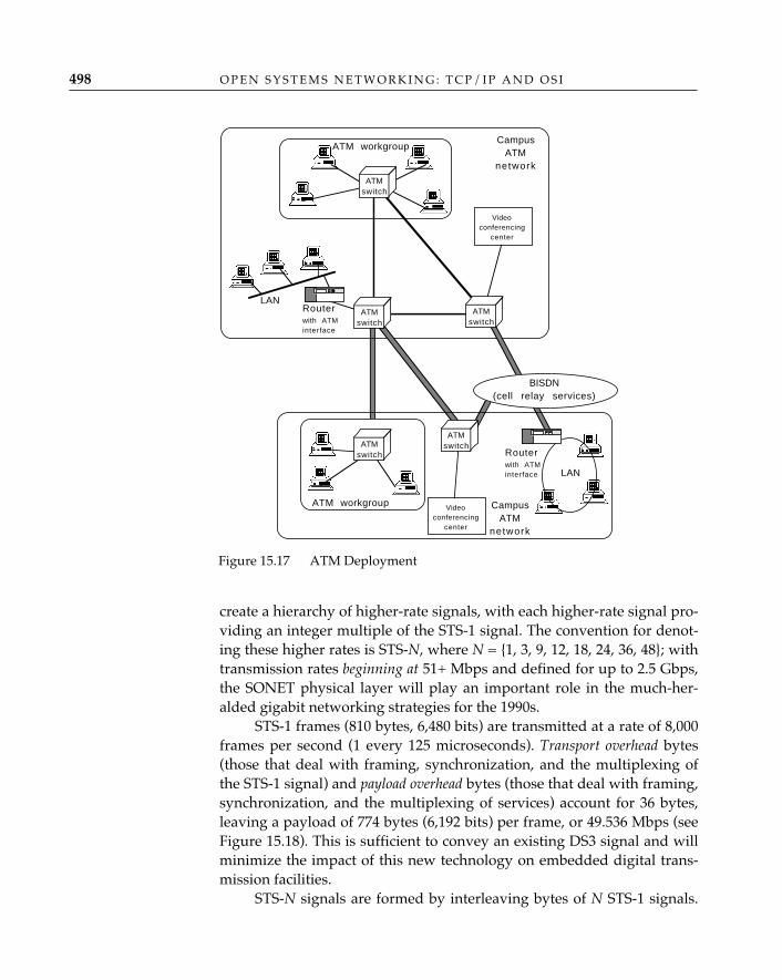
create a hierarchy of higher-rate signals, with each higher-rate signal pro-viding an integer multiple of the STS-1 signal. The convention for denot-ing these higher rates is STS-N, where N = {1, 3, 9, 12, 18, 24, 36, 48}; withtransmission rates beginning at 51+ Mbps and defined for up to 2.5 Gbps,the SONET physical layer will play an important role in the much-her-alded gigabit networking strategies for the 1990s.
STS-1 frames (810 bytes, 6,480 bits) are transmitted at a rate of 8,000frames per second (1 every 125 microseconds). Transport overhead bytes(those that deal with framing, synchronization, and the multiplexing ofthe STS-1 signal) and payload overhead bytes (those that deal with framing,synchronization, and the multiplexing of services) account for 36 bytes,leaving a payload of 774 bytes (6,192 bits) per frame, or 49.536 Mbps (seeFigure 15.18). This is sufficient to convey an existing DS3 signal and willminimize the impact of this new technology on embedded digital trans-mission facilities.
STS-N signals are formed by interleaving bytes of N STS-1 signals.
O P E N S Y S T E M S N E T W O R K I N G : T C P / I P A N D O S I498
ATM workgroup
ATMswitch
CampusATM
network
ATMswitch
Routerwith ATMinterface
BISDN(cell relay services)
ATMswitch Router
with ATMinterface LAN
LAN
ATM workgroup CampusATM
network
ATMswitch
Videoconferencing
center
Videoconferencing
center
ATMswitch
Figure 15.17 ATM Deployment
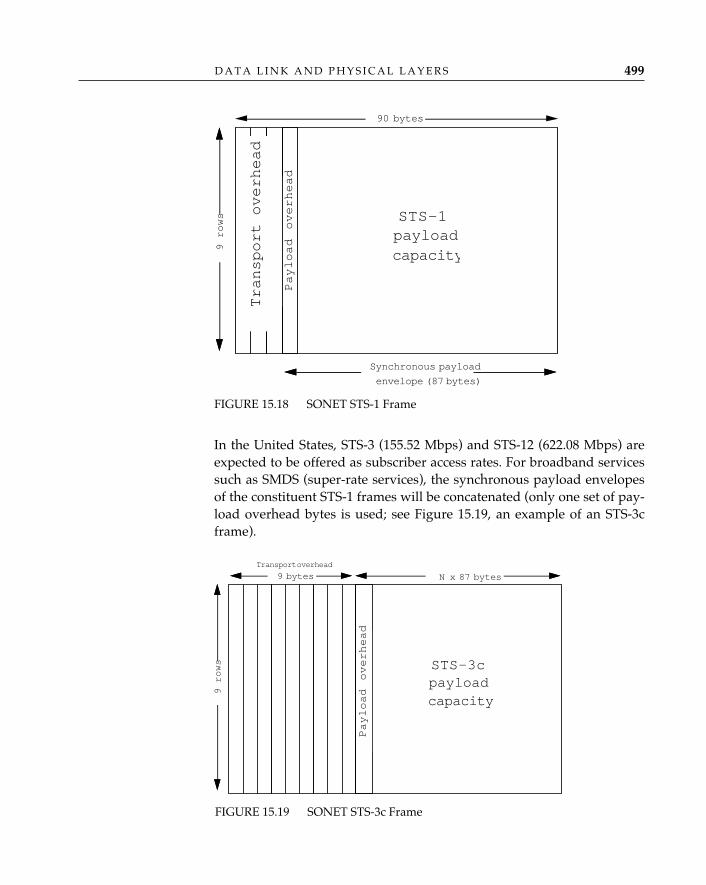
In the United States, STS-3 (155.52 Mbps) and STS-12 (622.08 Mbps) areexpected to be offered as subscriber access rates. For broadband servicessuch as SMDS (super-rate services), the synchronous payload envelopesof the constituent STS-1 frames will be concatenated (only one set of pay-load overhead bytes is used; see Figure 15.19, an example of an STS-3cframe).
D A T A L I N K A N D P H Y S I C A L L A Y E R S 499
FIGURE 15.18 SONET STS-1 Frame
90 bytes
Synchronous payload
envelope (87 bytes)
STS-1payloadcapacity
9 rows
Payload overhead
Transport overhead
STS-3cpayloadcapacity
N x 87 bytes
Transport overhead
9 bytes
9 rows
Payload overhead
FIGURE 15.19 SONET STS-3c Frame
The impact of SONET will be more economical than technological.The existence of a standard for optical transmission systems will eventu-ally make optical-to-electrical equipment a commodity, and commoditypricing will speed the deployment of fiber-based facilities by publictelecommunications providers.
Very High Bandwidth as an Enabling Vehicle for OSIIt is often suggested that the protocol overhead associated with OSI’supper layers is so great that very high bandwidth is needed simply toestablish an OSI application association; there are, for example, T-shirtsthat proclaim OSI to be “same-day service in a nanosecond world”.7
True, OSI’s upper layers have lots of header bits, and the ASN.1 syntaxhardly qualifies as a bit-economical form of data transfer, but (1) in amultimegabit environment, the overhead is not nearly so significant as itis in kilobit environments; (2) the flexibility introduced to the applicationwriter may be worth the overhead; and (3) end users care about the netresult of the application, not how it is encoded. And one simply cannotoverlook the fact that ATM itself is hardly the model for packetizing effi-ciency. The fact remains that if ATM technology succeeds at providingvery high bandwidth, and the cost is at or near the “willingness to pay,”ATM platforms offer the potential to remove some encumbrances fromdistributed applications; if “bandwidth on demand” becomes the trans-mission norm, full-color imaging, recorded and real-time video, andhigh-fidelity audio can be integrated into distributed applications. OSI’supper layers provide standard tools to develop such applications, overOSI and Internet transport services; ATM/SONET facilities provideenough transport that standard tools may be worth the overhead.
ConclusionNetwork architects sometimes imagine that networking happens fromthe “top down,” because that is how network architectures are often con-structed—the applications at the top are, after all, presumably the raisond’être of any network, so it makes sense to start with the requirements of
O P E N S Y S T E M S N E T W O R K I N G : T C P / I P A N D O S I500
7. Van Jacobson came up with this particular poke at OSI, which appears on the T-shirtjust below a graphic in which an elephant perches happily, if precariously, on a telephonewire stretched between sagging poles.
distributed applications and let those determine the functions that mustbe provided by successively lower layers. OSI demonstrates this ap-proach in its alternation of service definition and protocol specification ateach layer; in the OSI standards community, the generally accepted prac-tice has been for the group working on one layer to ask for ”require-ments” from the group working on the layer just above and to use thoserequirements to decide what should and should not be in the service def-inition for its layer. In the real world, however, things are not nearly sosimple.
The technologies that populate the data link and physical layers ofa network architecture do not arise in response to “requirements”expressed by standards developers working in the network layer. Theresearch and engineering that produce a new communications technolo-gy—fiber-optic transmission systems, for example, or token-ring localarea networks—are driven by a broad range of scientific and economicforces that are far stronger than the voices of standards developers (ornetwork architects) calling for the inclusion of a particular function in”the data link layer” or a particular feature in “the data link service”because it will help them to design network-layer protocol standards. Itis important, therefore to pay attention not just to what the service defin-itions for the two lower layers say ought to be provided but also to theactual capabilities of the link-level transmission technologies that havebeen and are constantly being applied to the construction of new datanetworks. In an open system standards context, the right question to askabout SMDS or ATM, for example, is not “Does it (or can it) provide theOSI data link service?” but “Could it be used as a subnetwork with anappropriate internetwork protocol?” No one who discovers a promisingnew data link transmission or switching scheme is likely to abandon itbecause “it doesn’t provide the OSI physical or data link service!” Thereal story of the data link and physical layers, therefore, is not how theyaccommodate “requirements” from above but how they embrace andexpress within a networking architecture the communication capabilitiesthat are perpetually welling up from the real world.
D A T A L I N K A N D P H Y S I C A L L A Y E R S 501
PA R T F I V E
THE FUTURE OF OPEN SYSTEMS NETWORKING
The world of open systems networking does not look the way industrypundits predicted it would less than a decade ago. The great open-sys-tem sirens of the eighties—homogeneity, uniformity, transition—are nowlargely silent; the new age of networking must embrace and accommo-date what appears to be a permanently heterogeneous mix of technolo-gies and standards. Having examined OSI and TCP/IP side by side andin some detail, it is instructive for us to discuss their present status in thereal world and to speculate on their future.
The Myth of “OSI Migration”By the mid-1980s, OSI was widely heralded as the gospel of a “new age”networking religion that would use the power of international standardsto achieve for data networks the same ubiquitous, multivendor connec-tivity that is enjoyed by users of the international telephone network.Even proprietary network architectures that explicitly eschew “open-ness” in favor of “optimal performance” began applying the language ofthe OSI reference model to describe the way in which their protocols andservices are organized (a favorite claim across the industry at that timewas, “Our architecture conforms to the OSI reference model”). Industrypundits of the eighties predicted that OSI would eventually dominate theworld of open systems networking, and the widely accepted inevitabilityof OSI at that time forced the issue of network evolution into a narrowbox: specifically, how to manage a “transition,” or “migration,” fromwhatever one currently had to OSI.
16 MULTIPROTOCOL OPEN SYSTEMS
505
Just as the evolution of a species is influenced by external condi-tions—climate, in particular—network evolution toward a single opensystems networking technology has been affected by the climate of theinformation-processing marketplace, which has too many networkingchoices. TCP/IP, DECnet, IPX, SNA, and AppleTalk are “durable, ifincompatible, and they just won’t die peacefully.”1 At the same time thatOSI was being touted as the networking technology of the future, networkadministrators were dealing with a major change in culture, as societyembraced electronic mail, distributed file service, and LAN operating sys-tems as part of its daily routine: networks were growing and the demandsof users were changing, and a wholesale shift to a new technology wasnot a high priority in the field. Vendors seized the opportunity to extendthe life cycle of existing technology rather than invest in a new one, andthe standards process provided them with a convenient excuse: “critical-path” standards—notably, routing and management—were not yet com-pleted, so many vendors decided to wait for closure before tackling OSI.Thus, the real networks of the world are running the bulk of their trafficover something other than OSI—SNA, DECnet, TCP/IP, or one of a hostof LAN protocols (often referred to as ”LAN operating systems”).
Many real networks are running something best described as “all ofthe above and then some.” In terms of deployment, the market presenceof TCP/IP dwarfs that of OSI and is likely to continue growing at a rapidpace for many years, no matter how many GOSIPs (government OSI pro-curement regulations) are adopted by national governments. TCP/IP isnow widely available and understood; it works; and it has benefitedenormously from decades of steady improvement in both the protocolsand their implementations. And it has carefully attended to the protec-tion of the installed base: more often than not, changes are introducedonly after lengthy evaluation of how those changes will affect TCP/IPnetworks already in operation.
The assertion that TCP/IP is fine for universities but will nevermake it in the commercial world—a myopic OSI bigot once called theInternet an “academic toy”—has been proved wrong: in 1990, 56 percentof the sales of TCP/IP-based networking equipment and software werein the traditional commercial market, and this figure is projected to riseto 77 percent by the end of 1993. It is important to recognize, too, that the
O P E N S Y S T E M S N E T W O R K I N G : T C P / I P A N D O S I506
1. A quote fron Dan Lynch, founder and chairman of Interop, Inc., and former mem-ber of the ARPANET team that assisted in the transition from NCP protocols to TCP/IP inthe early 1980s, found in Update: Interop ’92 Spring. If anyone would know about the diffi-culties of transitioning a network, it would be Dan.
strengths of OSI are for the most part also the strengths of TCP/IP; froma technical standpoint, the rationale for deployment of TCP/IP networksis no less compelling than the rationale for deployment of OSI networks.TCP/IP developers who recognize that there are useful lessons to belearned from the evolution of OSI (particularly in the upper layers) willbe building and selling TCP/IP networks long after OSI has establisheditself in the marketplace.
It is also important to recognize that the TCP/IP marketplace itselfis dwarfed by the cumulative share held by LAN operating systems suchas Novell Netware and Banyan Vines and that proprietary networkingsolutions continue to hold a formidable share as well. These alternativeswon’t die peacefully either. They play an important role in mainstreamdistributed processing and will continue to do so despite bureaucraticefforts to the contrary.
OSI Is an Alternative, Not a SubstituteAs a practical matter, perfect network homogeneity is no longer viewedas attainable or necessarily desirable. Marshall Rose’s “D-day conjec-ture” was anything but farfetched: TCP/IP-based networks already offerOSI application services alongside TCP applications (Rose 1990, 551).The change in climatic conditions now forces the issue of network evolu-tion onto an open field: the truly interesting issue is not how to provokeevery conceivable network architecture through a “transition to OSI” buthow to accommodate heterogeneity within a multiprotocol network archi-tecture. OSI is no longer the only alternative; it is one among many, andit will have to survive by the virtue of its own strengths.
So what are OSI’s strengths? Although it is often most harshlyattacked, one strength of OSI is its status as an international standard.This is of relatively small importance to a considerable proportion of theInternet community which tends to exclude the politics and diplomacyof international networking from its list of valid concerns; however, forothers, the imperatives driving the international acceptance of OSI were—and remain—impressive. OSI standards represent a powerful interna-tional alignment of computer vendor and telecommunication carrierinterests in market stability and predictability, augmented by the emer-gence of GOSIPs, which may ultimately have the political effect of mak-ing OSI the norm, rather than the exception, in many large contract bids.Whether networking technology should be determined by political fiat isnot at issue here; it is simply a fact that certain organizations will (per-
M U L T I P R O T O C O L O P E N S Y S T E M S 507
haps dogmatically) accept OSI because they feel they must. It should alsobe noted that a lucrative marketplace for OSI continues to exist amongcompanies that believe that OSI is a strategic imperative—for example,telecommunications equipment and service vendors, which constitute ahuge market for OSI to support public directory and message-handlingservices as well as internal “operations” (management services).
Another of OSI’s strengths is its applications infrastructure. From atechnical standpoint, the elaborate OSI upper-layer architecture—oftenmaligned as unnecessarily complex and a performance-stifling burden—will be increasingly important as sophisticated distributed-processingapplications enter the computing mainstream. Much of this is in evidencetoday, as the Internet community experiments with the OSI directory andmessage-handling applications over ISODE, RFC 1006, and TCP/IP. TheOSI Directory has become an increasingly important tool to the Internet;efforts to improve the response time for directory queries, complementedby efforts to reduce the overhead of directory user agents so that they canrun easily on desktop computers, will undoubtedly make the OSIDirectory a finer tool.
Because this book discusses OSI and TCP/IP together, it is in-evitable that the future of OSI will be highly colored with the perspectiveof “the future of OSI in the Internet.” But advocacy for OSI message-han-dling and directory services exists outside the Internet community to aneven greater extent than within. It is instructive to note that corporateinternets that have little or no connectivity to the Internet (due, in somecases, to a conscious effort to ensure complete privacy and security) andthat have, in some cases, little or no TCP/IP (especially environments inwhich PC and mainframe OSs are pervasive and UNIX is virtually non-existent) see OSI message-handling and directory services as providing awelcome reprieve from the proliferation of PC, proprietary, and home-brew mail gateways and directory services. Not surprisingly, the absenceof a single, dominant mail system like the Internet's SMTP and a univer-sal name system like the DNS in these environments has played to theadvantage of OSI.
OSI’s lower layers are also often treated with disdain, primarilybecause of the exaggerated “connections versus connectionless” inter-working problem, but also because of performance. Both of these criti-cisms will disappear over time. OSI’s strength in the lower layers is thatin architecture and implementation, it is very similar to TCP/IP. A verypositive side effect of GOSIPs is that they have forced system designers,implementers, and users to build and use “first-generation” OSI prod-ucts, if only to satisfy a checklist item on a “request for proposal” from a
O P E N S Y S T E M S N E T W O R K I N G : T C P / I P A N D O S I508
government agency. As a consequence of being coerced into implement-ing or, worse still, using OSI, implementers have begun to realize that thewidely advertised problems of performance and resource utilization arenot due to some inherently threatening “OSI baggage”; instead, they dis-cover that OSI’s lower layers can benefit from the experience and engi-neering expertise that have come gradually with TCP/IP. It is easy toforget that TCP/IP as it stands in 1993 is the result of nearly two decadesof improvement and refinement. And as with TCP/IP, experiments totrim fat from OSI will happen only after the fat has been distinguishedfrom the muscle. The process of improving OSI performance will acceler-ate as the expertise acquired by TCP/IP engineers is applied to theimplementation and refinement of OSI protocols—assuming, of course,that the TCP/IP engineers continue to overcome their initial disdain forOSI and that the OSI developers pay attention to what the TCP/IP engi-neers have to say.
It is a small matter of time and experience before improvements toOSI’s underlying transport service and solutions to the “connectionlessversus connection-oriented” interworking problem make these nonis-sues as well. Implementations of OSI’s transport class 4 have alreadybeen improved by the use of slow-start algorithms, dynamic window-adjustment mechanisms, and other forms of congestion avoidance andcontrol that are commonplace in TCP implementations. Implementersare also beginning to understand that in some cases—notably, the issueof efficiency in checksums—“apples are not being compared to apples”;the checksum used in TCP is faster, but the one used in TP4 is stronger.
The “connections versus connectionless” debate may also end soon.Although ISO has developed and adopted a technical report describing arecommended means of interworking between connection-oriented andconnectionless networks (ISO/IEC TR 10172: 1991), and the very finework of folks like Jeremy Onions has provided us with useful transportservice bridges, the authors speculate that attention to the “Tinkertoytransports and X.25” will wane as the decade closes, even among PTTsand public network providers, and that the application of TP4 over ISOCLNP as the recommended underlying transport service will be wide-spread. This speculation is based partly on the authors’ conviction thatthis is technically the right choice, also on the steadily increasing interestin IP and connectionless metropolitan-area network services throughoutEurope and North America.
In the minds of some, OSI will never be acceptable, in any form;and although it is unlikely ever to be the universal panacea for network-ing, it most certainly will do useful work for a sizable population. In the
M U L T I P R O T O C O L O P E N S Y S T E M S 509

Internet, it coexists alongside TCP/IP today and will continue to do sofor the forseeable future.
OSI and TCP/IP Coexistence: Networking DétenteIf integration, rather than migration, has become the issue, the questionremains “how to make it happen.” To date, several alternatives havebeen deployed with varying degrees of success. Some of these wereintroduced and discussed in Marshall Rose’s Open Book in the context of“transition to OSI”; here, the authors examine these alternatives with theluxury of hindsight, considering whether and how each has been appliedor extended and also placing the discussion in the context of “copingwith a multiprotocol environment.”
The simplest solution to the problem of multiple protocol architectures inthe Internet is to run each protocol “stack” independently in each system.Figure 16.1 illustrates how OSI and TCP/IP can be deployed as “dualstacks,” but the principle applies for multiple stacks as well. In the dual-stack approach, OSI and TCP/IP applications and protocols coexist butdo not interoperate—although they may be engineered to share the avail-
O P E N S Y S T E M S N E T W O R K I N G : T C P / I P A N D O S I510
Dual and“Multiple”Stacks
FIGURE 16.1 The Dual-Stack Approach
TCP/IPapplication
TCP/IPprotocolstack
OSI
internet
TCP/IP
internet
OSIapplication
OSIprotocolstack
TCP/IPapplication
TCP/IPprotocolstack
OSIapplication
OSIprotocolstack
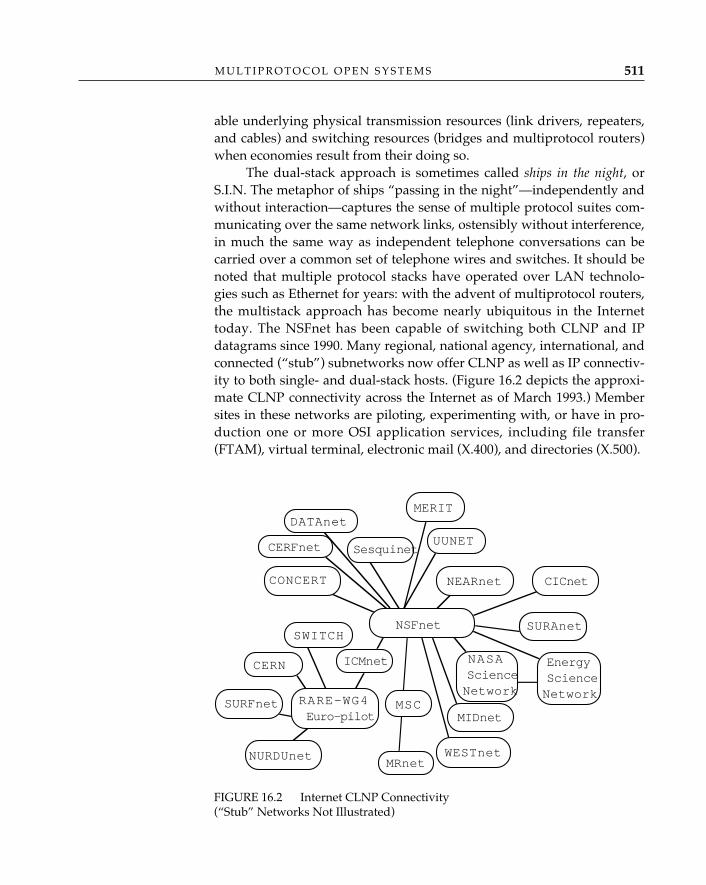
able underlying physical transmission resources (link drivers, repeaters,and cables) and switching resources (bridges and multiprotocol routers)when economies result from their doing so.
The dual-stack approach is sometimes called ships in the night, orS.I.N. The metaphor of ships “passing in the night”—independently andwithout interaction—captures the sense of multiple protocol suites com-municating over the same network links, ostensibly without interference,in much the same way as independent telephone conversations can becarried over a common set of telephone wires and switches. It should benoted that multiple protocol stacks have operated over LAN technolo-gies such as Ethernet for years: with the advent of multiprotocol routers,the multistack approach has become nearly ubiquitous in the Internettoday. The NSFnet has been capable of switching both CLNP and IPdatagrams since 1990. Many regional, national agency, international, andconnected (“stub”) subnetworks now offer CLNP as well as IP connectiv-ity to both single- and dual-stack hosts. (Figure 16.2 depicts the approxi-mate CLNP connectivity across the Internet as of March 1993.) Membersites in these networks are piloting, experimenting with, or have in pro-duction one or more OSI application services, including file transfer(FTAM), virtual terminal, electronic mail (X.400), and directories (X.500).
M U L T I P R O T O C O L O P E N S Y S T E M S 511
FIGURE 16.2 Internet CLNP Connectivity (“Stub” Networks Not Illustrated)
NSFnet
CERFnet
CERN
ICMNET
MIDnet
MERIT
RARE-WG4Euro-pilot
CERFnet
MSC
MRnet
Sesquinet
CERFnetDATAnetMERIT
CONCERT CICnet
SWITCH
SURFnet
NURDUnet
ICMnet
WESTnet
UUNET
NEARnet
SURAnet
NASAScienceNetwork
EnergyScienceNetwork
Dual (multiple) stacks are often the only way to accommodate morethan one protocol suite within a single system. However, the drawbacksdiscussed in the Open Book remain in evidence today:
• The dual-stack (multiple-stack) approach is expensive, since itrequires “two (many) of everything”: network management, soft-ware, protocol overhead, on-call systems-engineering expertise, andadministration of addresses, operation, software and equipmentupdates, and access control. This solution is expensive in the tradi-tional interpretation as well, as it often requires more CPU, morememory, and more storage to operate.
• It affects all systems. Hosts, in particular, must have two (many) ofeverything, and where multiprotocol switching systems (routers,bridges) cannot be deployed, parts of the infrastructure must beduplicated (multiplied).
• It often affects performance. Absent a perfect “memory and CPU arecheap” utopia, running two or more protocol stacks costs.
• It is difficult to achieve transparency. The UNIX socket() interfaceprovides access to both OSI and TCP/IP, but the services are dis-tinct. The same is true for the X/Open Transport Interface (XTI) andvarious application program interfaces (APIs); transparency is anelusive target.
• Unless all systems have dual (multiple) stacks, there will not becomplete interoperability.
Unless the protocol suites are implemented and deployed very care-fully, it may not be possible to avoid interference. When both protocolsuites are operated over the same transmission facilities, for example, andboth do not subscribe to the same philosophy of congestion avoidance, theeffectiveness of such feedback mechanisms as explicit “congestion-experi-enced bits” is compromised. Even when it is possible to prevent directinterference between two different protocol suites, the metaphorical shipscannot pass obliviously, as they must be subject to at least some form ofcommon system-management and resource-utilization arbitration.
The dual-stack (multiple-stack) approach typically accommodates diver-sity among protocol suites everywhere except at the very bottom of thestacks, where common physical interconnections among systems canoften be shared (this includes common data-link layer framing as well).Although this permits different protocol suites to share transmissionresources (with the constraints and compromises noted earlier), it doesnot provide for any interaction among them—although systems running
O P E N S Y S T E M S N E T W O R K I N G : T C P / I P A N D O S I512
ApplicationGateways
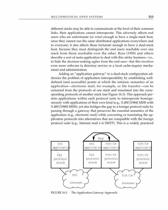
different stacks may be able to communicate at the level of their commonlinks, their applications cannot interoperate. This adversely affects endusers who are unfortunate (or wise) enough to have a single-stack host,since they cannot run the same distributed applications everywhere andto everyone; it also affects those fortunate enough to have a dual-stackhost, because they must distinguish the end users reachable over onestack from those reachable over the other. Rose (1990) and othersdescribe a sort of meta-application to deal with this sticky business—i.e.,to hide the decision-making uglies from the end user—but this involveseven more software (a directory service or a local cache-inquiry mecha-nism) and administration.
Adding an ”application gateway” to a dual-stack configuration ad-dresses the problem of application interoperability by establishing well-defined (and accessible) points at which the intrinsic semantics of anapplication—electronic mail, for example, or file transfer—can beextracted from the protocols of one stack and translated into the corre-sponding protocols of another stack (see Figure 16.3). This approach per-mits applications within each protocol suite to interoperate homoge-neously with applications of their own kind (e.g., X.400 [1984] MHS withX.400 [1988] MHS), yet also bridges the gap to a foreign protocol suite bypassing through a gateway that preserves the essential semantics of theapplication (e.g., electronic mail) while converting or translating the ap-plication protocols into alternatives that are compatible with the foreignprotocol suite (e.g., Internet mail à la SMTP). This is a widely practiced
M U L T I P R O T O C O L O P E N S Y S T E M S 513
FIGURE 16.3 The Application Gateway Approach
OSI
internet
TCP/IP
internet
OSIapplication
OSIprotocolstack
TCP/IPapplication
TCP/IPprotocolstack
TCP/IPapplication
TCP/IPprotocolstack
OSIapplication
OSIprotocolstack
Map
method of interconnecting users in the Internet today. Application gateways are natural for some applications, such as
store-and-forward electronic mail, that are designed to pass throughapplication-relay points in the normal course of events even in a homoge-neous environment. The results are much less satisfying for other distrib-uted applications—networked operating systems, file systems, distributeddatabase systems—where the paradigm for such distributed systems maydiffer radically: an application gateway situated between clients andservers of AT&T’s Remote File Service and Sun's Network File System isdecidedly more complicated than one involving X.400–to–RFC 822 mail;the entire paradigm for a distributed filestore differs more than onewould ever hope to reconcile in a gateway.
Application gateways also permit network managers to establishand monitor a strong administrative boundary between a local applica-tion environment (the campus mail network, for example) and the rest ofthe Internet; this is sometimes referred to as “outside-world contracep-tion.” And in some cases, of course, an application gateway is the onlyway to glue two otherwise oblivious environments together withoutchanging an operating system software in which the lower-layer protocolimplementations are embedded.
The unavoidable “least-common-denominator” effect of an applica-tion gateway is its worst drawback; users whose electronic mail traversesan X.400-1988–to–RFC 822 mail gateway, for example, may only be ableto send transparent ASCII text in the interpersonal message (and similar-ly, MIME users to X.400-1984 MHS). Users will generally have to bekeenly aware of the presence of the gateway (especially true when one isdealing with electronic mail addresses), and conduct their communica-tions accordingly, in order to achieve success. Every type of application,of course, requires its own special type of application gateway, and theproblem is exacerbated each time another stack is introduced—a separategateway or extension is then required for every pair of like applications(an X.400 MHS–to–RFC 822 mail gateway is a separate ordeal from anSMTP to PC LAN-based mail/messaging gateway); this is exactly the sit-uation in which many corporate internets having no “core” TCP/IP ser-vice find themselves.
Because the gateway must perform a fairly complicated transforma-tion on the data flowing through it, it often represents a performance bot-tleneck (for some applications, such as electronic mail, the performancedegradation is unobtrusive). Users must ensure that only one applicationgateway intervenes between the source and destination systems, since itis generally true that application gateways do not chain well. If an
O P E N S Y S T E M S N E T W O R K I N G : T C P / I P A N D O S I514
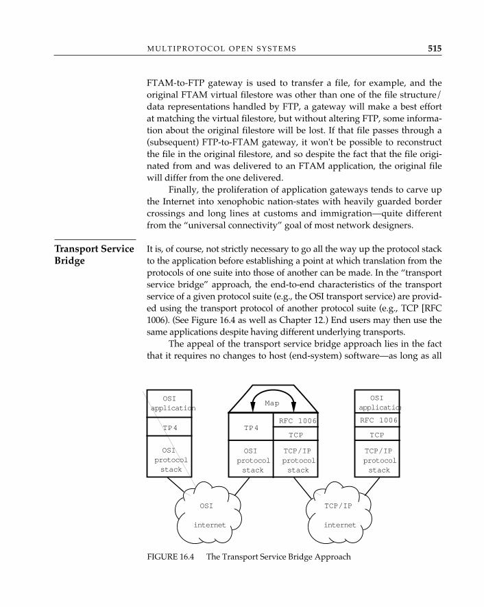
FTAM-to-FTP gateway is used to transfer a file, for example, and theoriginal FTAM virtual filestore was other than one of the file structure/data representations handled by FTP, a gateway will make a best effortat matching the virtual filestore, but without altering FTP, some informa-tion about the original filestore will be lost. If that file passes through a(subsequent) FTP-to-FTAM gateway, it won't be possible to reconstructthe file in the original filestore, and so despite the fact that the file origi-nated from and was delivered to an FTAM application, the original filewill differ from the one delivered.
Finally, the proliferation of application gateways tends to carve upthe Internet into xenophobic nation-states with heavily guarded bordercrossings and long lines at customs and immigration—quite differentfrom the “universal connectivity” goal of most network designers.
It is, of course, not strictly necessary to go all the way up the protocol stackto the application before establishing a point at which translation from theprotocols of one suite into those of another can be made. In the “transportservice bridge” approach, the end-to-end characteristics of the transportservice of a given protocol suite (e.g., the OSI transport service) are provid-ed using the transport protocol of another protocol suite (e.g., TCP [RFC1006). (See Figure 16.4 as well as Chapter 12.) End users may then use thesame applications despite having different underlying transports.
The appeal of the transport service bridge approach lies in the factthat it requires no changes to host (end-system) software—as long as all
M U L T I P R O T O C O L O P E N S Y S T E M S 515
Transport ServiceBridge
FIGURE 16.4 The Transport Service Bridge Approach
OSI
internet
TCP/IP
internet
OSIapplication
OSIprotocolstack
TCP/IPprotocolstack
TCP/IPprotocolstack
OSIprotocolstack
Map
TP4 TP4TCP
RFC 1006
TCP
RFC 1006
OSIapplication
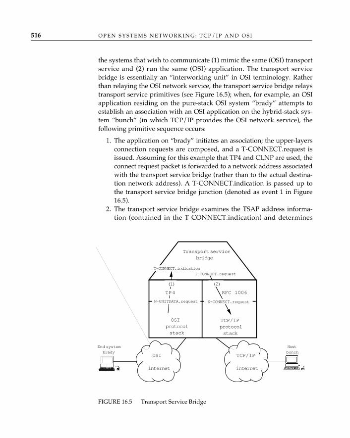
the systems that wish to communicate (1) mimic the same (OSI) transportservice and (2) run the same (OSI) application. The transport servicebridge is essentially an “interworking unit” in OSI terminology. Ratherthan relaying the OSI network service, the transport service bridge relaystransport service primitives (see Figure 16.5); when, for example, an OSIapplication residing on the pure-stack OSI system “brady” attempts toestablish an association with an OSI application on the hybrid-stack sys-tem “bunch” (in which TCP/IP provides the OSI network service), thefollowing primitive sequence occurs:
1. The application on “brady” initiates an association; the upper-layersconnection requests are composed, and a T-CONNECT.request isissued. Assuming for this example that TP4 and CLNP are used, theconnect request packet is forwarded to a network address associatedwith the transport service bridge (rather than to the actual destina-tion network address). A T-CONNECT.indication is passed up tothe transport service bridge junction (denoted as event 1 in Figure16.5).
2. The transport service bridge examines the TSAP address informa-tion (contained in the T-CONNECT.indication) and determines
O P E N S Y S T E M S N E T W O R K I N G : T C P / I P A N D O S I516
OSI
internet
TCP/IP
internet
TCP/IPprotocolstack
OSIprotocolstack
TP4
T-CONNECT.request
(1)
T-CONNECT.indication
RFC 1006
(2)
N-CONNECT.requestN-UNITDATA.request
End systembrady
Transport servicebridge
Hostbunch
FIGURE 16.5 Transport Service Bridge
from a local “transport-bridging table” that an RFC 1006 host is thetarget for this connection. Extracting the actual destination TSAPaddress, port, and IP number from the table, the transport servicebridge generates a T-CONNECT.request and attempts to establish atransport connection between itself and a transport server on “bunch”(denoted as event 2 in Figure 16.5).
3. Per RFC 1006, the T-CONNECT.request results in the establishmentof a transport connection between the transport server at “bunch”and the transport service bridge using a protocol functionally iden-tical to OSI transport protocol class 0 over TCP.
4. When the transport connection to “bunch” has been established,the transport service bridge confirms the establishment of the trans-port connection between itself and “brady.”
5. The upper-layer connection-establishment protocol packet is trans-ferred from “brady” to the transport service bridge in TP4 datapackets; at the bridge, the upper-layer protocol packet is forwardedover the TCP connection to “bunch” using the packetization schemedescribed in RFC 1006. The upper-layer connection-acceptance pro-tocol packet is returned over the reverse path. Following comple-tion of the upper-layer connection-establishment process, data ex-changes follow the same course.
The transport service boundary is often implemented as a program-matic interface between user programs and the host operating system.Chapter 12 describes how multiple transport stacks are accommodated inUNIX by extending the set of socket() types to include “sequenced packet”(seqpacket); other operating systems offering direct access to transportservices can apply similar extensions. The text description of the transportserver in RFC 1006 is a mere 8 pages; one might suspect that transportservice bridges similar to the one that makes use of RFC 1006 can easilybe defined for other non-OSI protocol architectures as well.
In fact, a transport service bridge offers a more attractive and sim-pler method of solving the problem of connection-oriented versus con-nectionless interworking in OSI than the transport relay described inISO/IEC TR 10172: 1991, since it easily accommodates scenarios in whichhosts using TP4 over CLNP wish to communicate with hosts using TP0over X.25. The transport service bridge approach today is a deployedand expedient choice for users who would like to introduce OSI applica-tions into an existing internet gradually and with little or no disruptionof day-to-day operations as well as users who have to cope with multipleOSI network services.
M U L T I P R O T O C O L O P E N S Y S T E M S 517
The transport service bridge approach succeeds more often than theapplication gateway approach in preserving not merely the essentialsemantics but all semantics of end-user applications. As one might expect,however, the transport service bridge approach is not without its prob-lems. The transport service bridge terminates the transport protocol oneither side, interrupting the end-to-end transport features of flow control,error detection and correction, and congestion avoidance (the latter usuallya collaboration with underlying network protocols). It also completelybreaks any security mechanisms that rely on cryptographic protection oftransport protocol header information (such as sequence numbers). Atransport service bridge represents a single point of failure in an other-wise dynamically adaptive internetwork. Also, because it must “spoof”the network addresses (so that each party thinks it is talking to the other,when in fact it is talking to the transport service bridge), it makes it muchmore difficult to diagnose routing problems in the internet.
Contrary to popular belief, the operation of a packetizationprotocol over TCP described in RFC 1006 is not the only (nor
the first) example of using a transport protocol to provide the OSI connection-oriented network service. In the mid-1980s, United Kingdom representatives toISO introduced a variation of OSI TP4 called “network protocol 4 (NP4)” andproposed it as an alternative to further modifying X.25 PLP for use in providingthe connection-oriented network service over connectionless local area networks.NP4 was a TP4 clone capable of conveying OSI NSAP addresses rather thanTSAP addresses and could run over CLNP or IEEE 802 LANs (encapsulated inlogical link control type 1 frames). NP4 would interwork at the network layer(between a private and public network) with the X.25 packet level protocol. Itfailed to catch on for the simple reason that it was not X.25, and not CLNP, andso had no natural constituency in the standards-development community.
The big win for transport service bridges (and transport relays, althoughwith greater complexity) is that they accommodate a “mix and match” ofapplications across multiple transport fabrics. In principle, and withappropriate transport service bridges, one can run OSI applications overTCP/IP, AppleTalk, etc. The transport service bridge most widely usedtoday is the OSI transport service bridge based on RFC 1006; however,with a transport service bridge designed to provide TCP’s stream service,one could certainly run TCP/IP applications over OSI transports.
✧AHA✧
O P E N S Y S T E M S N E T W O R K I N G : T C P / I P A N D O S I518
Hybrid Stacks
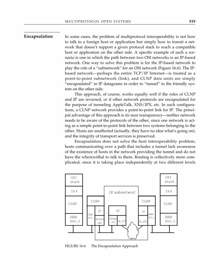
In some cases, the problem of multiprotocol interoperability is not howto talk to a foreign host or application but simply how to transit a net-work that doesn’t support a given protocol stack to reach a compatiblehost or application on the other side. A specific example of such a sce-nario is one in which the path between two OSI networks is an IP-basednetwork. One way to solve this problem is for the IP-based network toplay the role of a “subnetwork” for an OSI network (Figure 16.6). The IP-based network—perhaps the entire TCP/IP Internet—is treated as apoint-to-point subnetwork (link), and CLNP data units are simply“encapsulated” in IP datagrams in order to “tunnel” to the friendly sys-tem on the other side.
This approach, of course, works equally well if the roles of CLNPand IP are reversed, or if other network protocols are encapsulated forthe purpose of tunneling AppleTalk, XNS/IPX, etc. In such configura-tions, a CLNP network provides a point-to-point link for IP. The princi-pal advantage of this approach is its near transparency—neither networkneeds to be aware of the protocols of the other, since one network is act-ing as a simple point-to-point link between two systems belonging to theother. Hosts are unaffected (actually, they have no idea what’s going on),and the integrity of transport services is preserved.
Encapsulation does not solve the host interoperability problem;hosts communicating over a path that includes a tunnel lack awarenessof the existence of hosts in the network providing the tunnel and do nothave the wherewithal to talk to them. Routing is collectively more com-plicated, since it is taking place independently at two different levels
M U L T I P R O T O C O L O P E N S Y S T E M S 519
FIGURE 16.6 The Encapsulation Approach
OSIstack
TP4
CLNP
IEEE802.3
OSIstack
TP4
IEEE802.3
CLNP
IEEE
802.3
IP
Ether-net
Ether-
net
IP
CLNP
IEEE
802.3
X.25
IP
X.25
IP subnetwork
CLNP
Encapsulation
(network and “subnetwork”) for paths that include a tunnel (good newsfor router vendors). Over some paths—if one tunnels across the Internetusing the standard 576-octet IP datagram maximum segment size, forexample—link efficiency goes to hell in a handbasket.
At present, no standard exists for operating OSI’s connectionless net-work protocol (CLNP) over TCP/IP’s internetwork protocol. Althoughconceptually straightforward, details such as the identification of “encap-sulated” protocols, efficient route selection, the use of IP addresses as “sub-network addresses,” segmentation efficiency, and packet size negotiationmust be considered. Tunneling, however, is widely practiced across theInternet and is not restricted to the network layer; IBM SNA traffic is fre-quently encapsulated in TCP/IP packets, and AppleTalk traffic is con-veyed using IP encapsulation (and vice versa in AppleTalk networks).
Bringing OSI into a NetworkFor some, the question remains, “Given these alternatives, how do Ibring OSI into my network?” Here, then, is a practical scenario.
Step 1: Introduce OSI Applications in a “Hybrid-Stack” EnvironmentBring OSI applications to TCP/IP hosts by (1) using the RFC 1006 tech-niques to run the OSI upper layers over the TCP transport interface pro-vided by the host operating system software and (2) using applicationgateways (particularly for electronic mail) to tie together OSI and TCP/IP application environments that cannot be changed. The benefit of thismethod of introduction is that end users get to play with OSI applica-tions while the network infrastructure remains the same (see the networkadministrator smile). End users also don’t have to completely cut over tonew applications—the existing applications remain available. OSI appli-cations still don’t talk to TCP/IP applications, but needs in this area canbe satisfied with gateways. Note that by applying the RFC 1006 princi-ples, this strategy can be employed in corporate internets that have“core” transport services other than TCP/IP.
Step 2: Build TS Bridges—Use TS bridges to bring new OSI-only hostsinto the TCP/IP network as they become available. Dual-stack hosts maybe configured to use either transport service; the choice will depend onthe direction the “internet” is taking (e.g., if there is to be an eventualcutover to primarily OSI service, it might be desirable to bring dual-stackhosts onto the OSI backbone). Again, note that by applying the transportservice bridge principles, this strategy can be employed in corporate
O P E N S Y S T E M S N E T W O R K I N G : T C P / I P A N D O S I520
internets that have “core” transport services other than TCP/IP.
Step 3: Expand the Network Infrastructure to Include OSI—As OSI-onlyor multiprotocol routers (which can route both OSI and TCP/IP traffic)replace or complement IP-only routers in the network, begin to use OSItransport services as host operating system software with embedded OSItransport comes on line. If absolutely necessary, carry TCP/IP-only hostsalong with IP-over-CLNP encapsulation.
If homogeneity is an absolute must for a given enterprise network,and OSI is an imperative, routers initially placed to switch both CLNPand IP datagrams can be gradually configured to switch only CLNP dataunits, and traffic from TCP/IP hosts can be tunneled using CLNP. This isa highly unlikely scenario for the Internet; rather than solving interoper-ability problems, it merely swings the pendulum to the left rather thanthe right.
Step 4: Learn to Rely on Names, Not Numbers—Wherever possible, relyon a centrally administered (if operationally distributed) directory ser-vice to keep track of the mappings between names and the attributes as-sociated with them.
OSI has been—and continues to be—successfully introduced into partsof the existing Internet, alongside TCP/IP using steps 1 through 3 (step 4is coming). OSI applications appeared first in the Internet over ISODEand RFC 1006, and gateway experiments followed shortly thereafter.From the gateway experiences, the Internet community learned to appre-ciate the transport service bridge approach and has popularized it.
The evolution toward a “dual-stack” Internet (step 3) has proceededin the same fashion as ripples spreading out from a stone thrown into apond. The NSFnet staff introduced CLNP alongside IP in the backbonewhile most end users were busily going about their business runningapplications over IP, and others were experimenting with ISODE andOSI applications over RFC 1006. Several regional and commercial IP sub-networks are now proceeding with their introduction of CLNP in thesame manner, and the attached “stub” networks, encouraged by thepresence of backbone CLNP connectivity, are likely to follow suit. Ap-plications running on OSI and dual-stack hosts can reach IP-only hosts ofthe Internet via transport service bridges and application gateways.
M U L T I P R O T O C O L O P E N S Y S T E M S 521
Why Is This Scenario Practical?
Are the Instrumentation and Expertise Available to Operate OSINetworks?
Network administrators who remain skeptical or unconvinced will ask,“What problems can I expect to run into when I introduce OSI into mynetwork?” OSI demonstrations at Interop and continued OSI testingacross the Internet have revealed a great deal of what one can expectwhen integrating OSI alongside TCP/IP (Hares92, Connexions). Initially,there will be a limited pool of network operators and engineers familiarwith OSI protocols. Tools for diagnosing problems with OSI protocolsexist, but not for all products. Fortunately, the Network OSI Operations(NOOP) Working Group in the IETF, along with working groups in RIPEand RARE, are preparing the way for OSI operations staff in emergingOSI environments. There is, for example, an OSI equivalent to ping (RFC1139), which has been incorporated into the second edition of CLNP.There is also an OSI traceroute that uses increasing values of the CLNPlifetime field of the echo packet in the same manner as IP trace-route usestime-to-live. Implementations will gradually offer utilities such as rout-ing table dumps. Multiprotocol systems in particular may use TCP/IP'sSimple Network Management Protocol over OSI (RFC) to collect routinginformation from the CLNS management information base (RFC 1238),while purist-stack OSI implementations may use the OSI common man-agement information protocol (CMIP) to accomplish the same feats.
Many of these problems may all but disappear if the Network LayerOSI Operations working group of the IETF is successful in establishing apermanent, readily available OSI test bed within the Internet. The Inter-net community has benefited for years from the practice of using the re-sources of the community—the Internet protocols and applications—tounderstand how networks work, and the community has openly sharedits experiences conducting daily IP operations. There is no reason to as-sume that the same recipe should not succeed for OSI.
ConclusionThe Internet becomes more commercialized each day. The cost of
“Internet access” through electronic mail is in some places comparable tothe cost of plain old telephone service. Even “host access” is within reachof small-business and residential consumers. On-line information avail-able via the Internet is no longer confined to science, engineering, and
O P E N S Y S T E M S N E T W O R K I N G : T C P / I P A N D O S I522
technology, and information retrieval tools make navigating through the“maze of data” child’s play. You can even send electronic mail to theWhite House; more importantly, the White House can send electronicmail to Congress!
Whether any of the competing technologies now deployed through-out the Internet or in enterprise networks is “best” has become a largelyirrelevant question. The Internet is multiprotocol, and is likely to remainso for the forseeable future, if not forever. The application of gateways,hybrid stacks, service bridges, and tunneling described in this chapterwill inevitably grow as people who neither know nor care what protocolstack they use make the Internet as fundamental to their daily lives asthe telephone.
M U L T I P R O T O C O L O P E N S Y S T E M S 523
A common thread and an inherent weakness among the existing alterna-tives for bringing OSI and other protocols into the Internet is that theyapproach the problem in a patchwork fashion. A potential alternative tothe four methods described in Chapter 16 for accommodating multipleprotocols in the Internet has emerged from a series of workshops spon-sored by the Internet Architecture Board. Consideration of the way inwhich the concept of “the Internet” has evolved since its inception has ledto the formulation of a proposal that might be called “a new multiproto-col architecture for the Internet.” In this chaper, the authors present abrief and highly speculative look into the possible future of the Internet.1
What Is “the Internet”?It is very difficult to deal constructively with the issue of “the multipro-tocol Internet” without first determining what “the Internet” is (orshould be). In this context, it is important to distinguish the Internet (aset of communicating systems) from the Internet community (a group ofpeople and organizations). Most people would accept a loose definitionof the latter as “the group of people who regard themselves as being partof the Internet community”; however, no such “sociological” definitionof the Internet itself is likely to be useful.
17AN ARCHITECTURAL ALTERNATIVE FOR THE INTERNET
525
1. These ideas emerged at the Internet architecture workshop held at the San DiegoSupercomputer Center in June 1991. The participants in that workshop deserve much of thecredit—such as it may be—for the contents of this chapter; see RFC 1287.
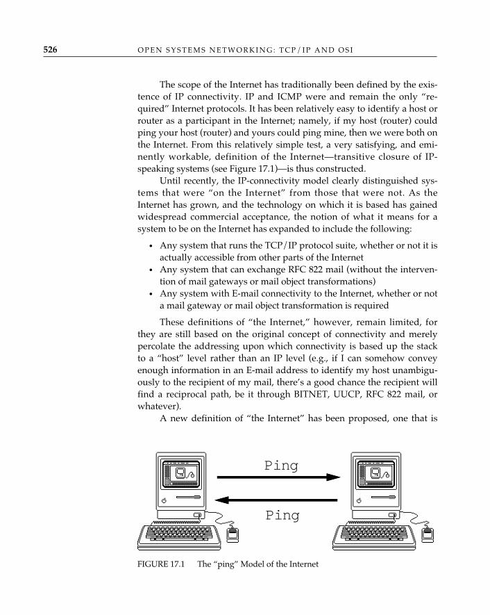
The scope of the Internet has traditionally been defined by the exis-tence of IP connectivity. IP and ICMP were and remain the only “re-quired” Internet protocols. It has been relatively easy to identify a host orrouter as a participant in the Internet; namely, if my host (router) couldping your host (router) and yours could ping mine, then we were both onthe Internet. From this relatively simple test, a very satisfying, and emi-nently workable, definition of the Internet—transitive closure of IP-speaking systems (see Figure 17.1)—is thus constructed.
Until recently, the IP-connectivity model clearly distinguished sys-tems that were “on the Internet” from those that were not. As theInternet has grown, and the technology on which it is based has gainedwidespread commercial acceptance, the notion of what it means for asystem to be on the Internet has expanded to include the following:
• Any system that runs the TCP/IP protocol suite, whether or not it isactually accessible from other parts of the Internet
• Any system that can exchange RFC 822 mail (without the interven-tion of mail gateways or mail object transformations)
• Any system with E-mail connectivity to the Internet, whether or nota mail gateway or mail object transformation is required
These definitions of “the Internet,” however, remain limited, forthey are still based on the original concept of connectivity and merelypercolate the addressing upon which connectivity is based up the stackto a “host” level rather than an IP level (e.g., if I can somehow conveyenough information in an E-mail address to identify my host unambigu-ously to the recipient of my mail, there’s a good chance the recipient willfind a reciprocal path, be it through BITNET, UUCP, RFC 822 mail, orwhatever).
A new definition of “the Internet” has been proposed, one that is
O P E N S Y S T E M S N E T W O R K I N G : T C P / I P A N D O S I526
FIGURE 17.1 The “ping” Model of the Internet
Ping
Ping
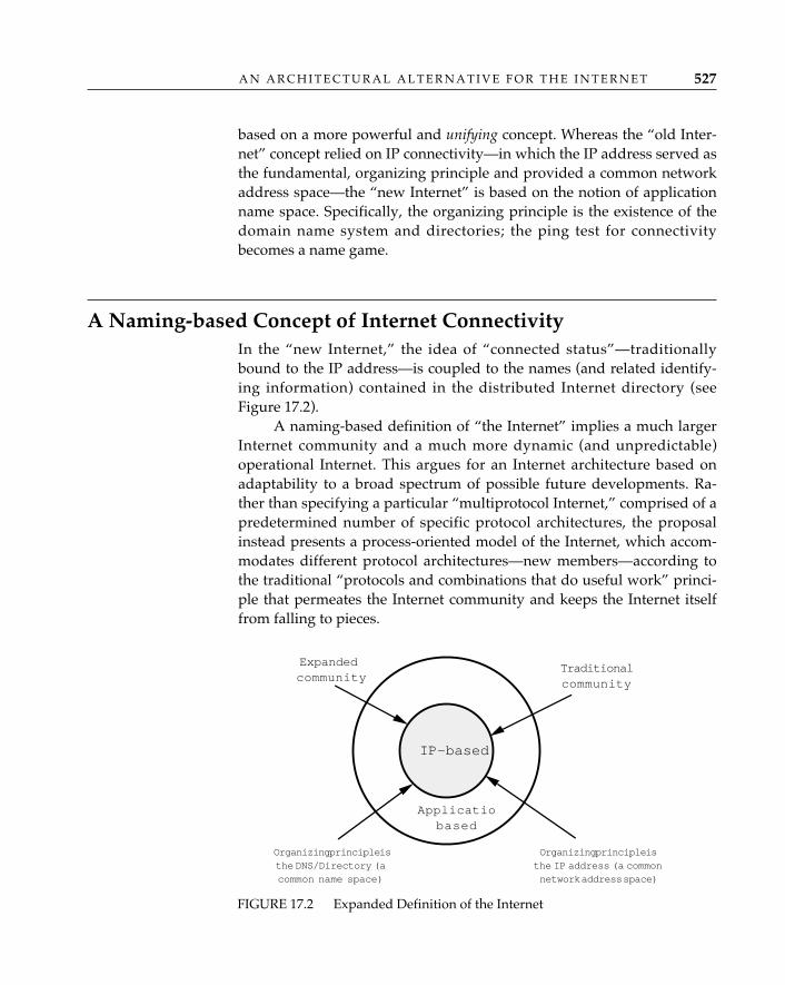
based on a more powerful and unifying concept. Whereas the “old Inter-net” concept relied on IP connectivity—in which the IP address served asthe fundamental, organizing principle and provided a common networkaddress space—the “new Internet” is based on the notion of applicationname space. Specifically, the organizing principle is the existence of thedomain name system and directories; the ping test for connectivitybecomes a name game.
A Naming-based Concept of Internet ConnectivityIn the “new Internet,” the idea of “connected status”—traditionallybound to the IP address—is coupled to the names (and related identify-ing information) contained in the distributed Internet directory (seeFigure 17.2).
A naming-based definition of “the Internet” implies a much largerInternet community and a much more dynamic (and unpredictable)operational Internet. This argues for an Internet architecture based onadaptability to a broad spectrum of possible future developments. Ra-ther than specifying a particular “multiprotocol Internet,” comprised of apredetermined number of specific protocol architectures, the proposalinstead presents a process-oriented model of the Internet, which accom-modates different protocol architectures—new members—according tothe traditional “protocols and combinations that do useful work” princi-ple that permeates the Internet community and keeps the Internet itselffrom falling to pieces.
A N A R C H I T E C T U R A L A L T E R N A T I V E F O R T H E I N T E R N E T 527
Traditionalcommunity
Expandedcommunity
IP-based
Applicatiobased
Organizing principle isthe IP address (a commonnetwork address space)
Organizing principle isthe DNS/Directory (acommon name space)
FIGURE 17.2 Expanded Definition of the Internet
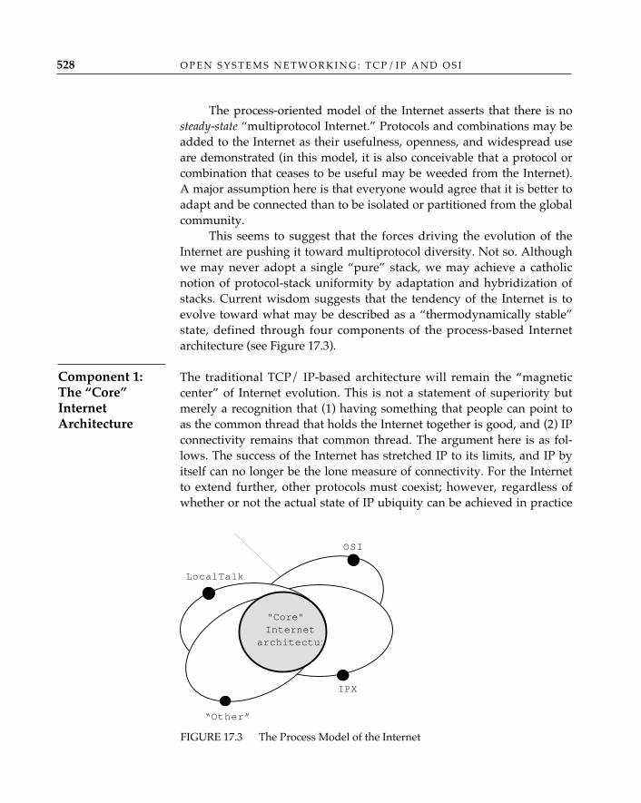
The process-oriented model of the Internet asserts that there is nosteady-state “multiprotocol Internet.” Protocols and combinations may beadded to the Internet as their usefulness, openness, and widespread useare demonstrated (in this model, it is also conceivable that a protocol orcombination that ceases to be useful may be weeded from the Internet).A major assumption here is that everyone would agree that it is better toadapt and be connected than to be isolated or partitioned from the globalcommunity.
This seems to suggest that the forces driving the evolution of theInternet are pushing it toward multiprotocol diversity. Not so. Althoughwe may never adopt a single “pure” stack, we may achieve a catholicnotion of protocol-stack uniformity by adaptation and hybridization ofstacks. Current wisdom suggests that the tendency of the Internet is toevolve toward what may be described as a “thermodynamically stable”state, defined through four components of the process-based Internetarchitecture (see Figure 17.3).
The traditional TCP/ IP-based architecture will remain the “magneticcenter” of Internet evolution. This is not a statement of superiority butmerely a recognition that (1) having something that people can point toas the common thread that holds the Internet together is good, and (2) IPconnectivity remains that common thread. The argument here is as fol-lows. The success of the Internet has stretched IP to its limits, and IP byitself can no longer be the lone measure of connectivity. For the Internetto extend further, other protocols must coexist; however, regardless ofwhether or not the actual state of IP ubiquity can be achieved in practice
O P E N S Y S T E M S N E T W O R K I N G : T C P / I P A N D O S I528
Component 1:The “Core”InternetArchitecture
OSI
IPX
"Core"Internet
architectur
LocalTalk
“Other”
FIGURE 17.3 The Process Model of the Internet
in a global operational Internet, it is generally recognized that “gettingthere using IP” is a good thing.
Two additional components of the new Internet architecture ex-press the ways in which the scope and extent of the Internet have beenexpanded.
Physical resources (transmission media, network interfaces) will be sharedby multiple, noninteracting protocol suites. The necessity and convenienceof coexistence at this level is not at issue; issues of how common resourcesare to be managed, how to minimize the degree to which protocol suitesinterfere with each other, and how to create “equal access” in real Internetsystems are critical to the continued success of the Internet. The Internetcannot grow without new controls or the means to extend existing controlsacross a multiprotocol platform; without these, prospects for a multiproto-col Internet would be grim.
What controls are needed and for what resources? Currently, thereare communities interested in providing type of service routing, effectiveimplementation of the notions of IP precedence, CLNP priority, and OSI’sembarrassingly vague QOS within the framework of the existing “best-effort delivery,” datagram environment of the Internet. There is a desireto introduce alongside these improvements an effective means of allocat-ing or reserving resources so that applications such as packet voice,video, and teleconferencing might be supported across the Internet. Theseimply capabilities that are not currently accommodated in the Internet(there is a tendency to conclude that applications such as these require“connections,” but it isn’t necessarily the case that these connections mustadhere to the traditional model of the “telephone call”).
Beyond these controls, there are additional levels of control that areequally important: policy, access control, and accounting must all be im-proved.
In those circumstances in which it is not possible to achieve interoper-ability among (all) the underlying protocol stacks, it is still possible toachieve application ubiquity, through the deployment of gateways. Theultimate role of the Internet is to serve as a basis for communicationamong applications. At a minimum, the Internet should enable commu-nities of end users sharing a common application “objective”—amongthese, the exchange of electronic mail, files, documents, images, andaccess to remote resources—but having diverse applications as “tools” tooperate and migrate from one underlying protocol suite to another with-out unacceptable loss of functionality.
A N A R C H I T E C T U R A L A L T E R N A T I V E F O R T H E I N T E R N E T 529
Component 2:“Link Sharing”
Component 3:ApplicationInteroperability
The scope of the Internet and the size of the Internet community areexpanded considerably by these changes, but at a cost. The Internet maybecome harder to administer from backbone to individual hosts. The costof multiprotocol hardware, software, and support and administrativestaff increases as well. Accounting, accountability, and security are nolonger merely important but essential. The changes are unavoidable, butthey are not painless, and each time functionality is lost, or additionalsystem complexity and costs are endured in order to expand the scope ofthe Internet, the decision to grow out from the “warm and comfy” worldof IP connectivity will be subjected to renewed harsh scrutiny. In a per-fect world, however, the Internet would evolve and expand withoutthese penalties; there is a tendency, therefore, for the Internet to evolve infavor of the homogeneous architecture represented by component 1, andaway from the compromised architectures of components 2 and 3.Component 4 expresses this tendency.
This component expresses the tendency of the Internet, as a system, toattempt to return to the original “state of grace” represented by the uni-form architecture of component 1. It is a force acting on the evolution ofthe Internet rather than a process whereby the Internet actually returns toa uniform state at some point in the future. Component 4 recognizes thedesirability of integrating similar elements from different Internet proto-col architectures to form hybrids that reduce the variability and complex-ity of the (central) Internet system. It also recognizes the desirability ofleveraging the existing Internet infrastructure to facilitate the absorptionof “new stuff” into the Internet, applying to “new stuff” the establishedInternet practice of test, evaluate, adopt.
The result is something akin to bombarding the nucleus of an atom withneutrons (the neutrons here being complementary or replacement proto-cols for the existing “core” stack). According to this dynamic model, run-ning X.400 mail over RFC 1006 on a TCP/IP stack, integrated IS-IS routing,transport bridges, and the development of a single common internetworkprotocol successor to IP and CLNP are all examples of “good things”2—they represent movement away from the nonuniformity of components 2and 3 in the direction of greater homogeneity, under the influence of the“magnetic field” asserted by component 1, following the hybridizationdynamic of component 4. Thus, homogeneity is accommodated not throughadoption of a single, “pure” stack but through widespread implementation
O P E N S Y S T E M S N E T W O R K I N G : T C P / I P A N D O S I530
Component 4:Hybridization/Integration
2. The authors wish to emphasize that these are merely examples and are not intend-ed to suggest that the very fine work done to produce MIME and OSPF should be set aside!
of the protocols and combinations that compose the “core.”What protocols and combinations will (initially) comprise the “core”
remains highly speculative. Certainly, the existing TCP/IP “stack” willremain in the core (including ARP, OSPF, and BGP-something); these arelikely to be complemented by CLNP and integrated IS-IS routing, theOSI directory and message-handling applications, and the RFC 1006transport service bridges. Because of its virtual ubiquity among IP-basedsystems, the simple network management protocol (SNMP) is likely toremain the fundamental management component; it now runs over anOSI stack, as will its heir apparent, SNMP version 2.
This is, of course, highly speculative and considers only the com-plementing items from OSI. Depending upon stakeholders’ interest inmaking other networking technologies “open,” and their willingness todo so, the “core” may be complemented by applications and services ofcurrent, proprietary, or de jure networking architectures.
A N A R C H I T E C T U R A L A L T E R N A T I V E F O R T H E I N T E R N E T 531

If a history of computer networking were to be written in the formand fashion of the King James Bible, the book of Genesis (Genebits . . .)might describe the final 40 years of the present millennium in this manner:
IInn tthhee bbeeggiinnnniinngg,, GGoodd ccrreeaatteedd tthhee hheeaavveennss aanndd tthheeeeaarrtthh.. HHee ppeerrffoorrmmeedd wwoonnddeerrss ooff eevveerryy ssoorrtt aanndd ccrreeaatteedd MMaanniinn HHiiss oowwnn iimmaaggee.. UUnnffoorrttuunnaatteellyy,, MMaann ssccrreewweedd uupp bbiigg ttiimmee,,aanndd GGoodd sseenntt hhiimm ppaacckkiinngg ((GGeenn.. 11,, 22)).. GGeenneerraattiioonnss ffoolllloowweeddggeenneerraattiioonnss ((GGeenn.. 33––1100)),, aanndd MMaann ffrreeqquueennttllyy ccrroosssseedd tthhee lliinneeaanndd GGoodd ddoolleedd oouutt ppuunniisshhmmeenntt aaccccoorrddiinnggllyy..
TThhrroouugghh tthheessee ggeenneerraattiioonnss,, aallll mmeenn uusseedd tthhee ssaammee llaanngguuaaggeeaanndd tthhee ssaammee wwoorrddss.. OOnnee ssuunnnnyy mmoorrnniinngg,, MMaann aassppiirreedd ttoorreeaacchh tthhee hheeaavveennss aanndd bbeeggaann ttoo bbuuiilldd ttoowweerrss aanndd ssuucchh.. GGooddssaaiidd,, ““NNoott!!,,”” ccoonnffuusseedd tthhee llaanngguuaaggee ooff tthhee wwhhoollee eeaarrtthh,, aannddttoowweerrss hhaavvee bbyy aanndd llaarrggee bbeeeenn mmooddeesstt eeffffoorrttss ssiinnccee tthheenn((GGeenn.. 1111))..
MMaann eevveerr aafftteerr ssoouugghhtt ttoo hhaavvee tthhee wwhhoollee eeaarrtthh uussee tthhee ssaammeellaanngguuaaggee aanndd tthhee ssaammee wwoorrddss.. HHee ssttrruugggglleedd aaggeess uuppoonn aaggeessuunnttiill hhee ddiissccoovveerreedd eelleeccttrriicciittyy aanndd mmiinneedd ccooppppeerr,, aanndd wweeddtthhee ttwwoo ttooggeetthheerr wwiitthh ddeevviicceess ooff aa ccuurriioouuss nnaattuurree,, aanndd ccoonn--dduucctteedd tthhee eelleeccttrriicciittyy oovveerr ccooppppeerr wwiirree iinn eevveerryy mmaannnneerr aannddkkiinndd uunnttiill ffiinnaallllyy MMaann ssaaiidd,, ““LLeett tthheerree bbee ccaarrrriieerr..””
AAnndd MMaann ssaaww tthhaatt ccaarrrriieerr wwaass ggoooodd aanndd tthhaatt ddiiggiittss ooff bbiinnaarryyccoouulldd rriiddee tthhee ccaarrrriieerr.. TThhee ““bbiittss”” wweerree ffoorrmmeedd iinnttoo wwoorrddss,,ffiirrsstt iinn tthhee llaanngguuaaggee ooff MMoorrssee aanndd llaatteerr ooff BBaauuddoott,, wwhhiicchh
18 A READING FROM THEBOOK OF GENEBITS
533

eennhhaanncceedd tthhee llaanngguuaaggee.. AAnndd tthhee ddeevviicceess wweerree tteelleexxeess aannddwwoonnddrroouuss iinnddeeeedd.. BBuutt tthhee llaanngguuaaggee wwaass ccoonnssttrraaiinniinngg,, tthheebbiittss nnuummbbeerriinngg oonnllyy 55,, aanndd MMaann ssaaww tthhaatt mmoorree bbiittss wweerreenneeeeddeedd aanndd ssaaww aallssoo tthhaatt tthhee bbiittss mmuusstt ttrraavveell ffaasstteerr..
BBuutt MMaann ssaaww aallssoo tthhaatt tthhee ccaarrrriieerr hhaadd nnoott tthhee ssttrreennggtthh,, ffoorrbbiittss wweerree iinnddeeeedd lloosstt oorr ddeessttrrooyyeedd aass tthheeyy ttrraavveelleedd oovveerr tthheeccooppppeerr wwiirree——vveerriillyy,, aatt tthhee ddiizzzzyyiinngg rraatteess ooff 330000––11,,220000 bbiittssppeerr sseeccoonndd——ssoo MMaann ggrroouuppeedd tthhee bbiittss iinnttoo 88,, aanndd ffrraammeedd tthheebbiittss ffiirrsstt wwiitthh ssttaarrtt bbiittss aanndd ssttoopp.. AAfftteerr aa ttiimmee,, tthhee 88--bbiitt bbyytteesstthheemmsseellvveess ffrraammeedd tthhee bbiittss ooff ggoooodd aanndd nnoobbllee uussee,, aanndd tthheeffrraammiinngg bbyytteess wweerree ccaalllleedd hheeaaddeerr aanndd tthhee nnoobbllee bbiittss uusseerr ddaattaa,,rreessppeeccttiivveellyy,, aanndd MMaann ssaaww tthhaatt tthhiiss,, ttoooo,, wwaass ggoooodd.. AAnndd tthheeddeevviicceess wweerree mmaaiinnffrraammeess aanndd wwoonnddrroouuss iinnddeeeedd.. NNooww ccooppppeerrccoonnnneecctteedd tthhee mmaaiinnffrraammeess,, ttwwoo bbyy ttwwoo,, aanndd tthhee wwhhoollee eeaarrtthhuusseedd vveerryy nneeaarrllyy tthhee ssaammee llaanngguuaaggee aanndd tthhee ssaammee wwoorrddss,, ffoorrtthhee mmaaiinnffrraammeess wweerree bbuutt eeiitthheerr bblluuee oorr ffrroomm tthhee BBUUNNCCHH..
AAnndd MMaann uusseedd tthhee llaanngguuaaggee,, aanndd tthhee llaanngguuaaggee ggrreeww aanndd yyeettmmoorree bbiittss wweerree nneeeeddeedd,, aanndd nnoo lloonnggeerr ccoouulldd tthhee mmaaiinnffrraammeessbbee ccoonnnneecctteedd ttwwoo bbyy ttwwoo,, ffoorr aammoonnggsstt tthhee ddeevviicceess wweerree nnoowwmmiinniiss aanndd mmiiccrrooss,, aanndd tthheeyy wweerree pplleennttiiffuull iinnddeeeedd,, aanndd tthheebbaannddwwiiddtthh ooff oonnee ccooppppeerr ppaaiirr wwaass iinnddeeeedd ttoooo ssmmaallll,, aanndd ccoopp--ppeerr ppaaiirrss ccoonnttiinnuueedd ttoo bbee aaddddeedd,, aanndd tthhee ccooppppeerr bbeeccaammee aarreeaall mmeesshh ((ssoorrrryy .. .. ..)),, aanndd aammoonngg MMeenn tthheerree wweerree ssoorrcceerreerrssaanndd aapppprreennttiicceess——RRoobbeerrttss,, CCeerrff,, PPoosstteell,, CCrroocckkeerr,, KKaahhnn,, aannddmmoorree——wwhhoo ccrreeaatteedd mmoorree hheeaaddeerr aanndd ccaauusseedd IIMMPPiisshh ddeevviicceess ttoosswwiittcchh,, aanndd tthhee ddeevviicceess aanndd tthhee ccooppppeerr wweerree oonnee aanndd tthhee oonneewwaass ccaalllleedd nneettwwoorrkk,, aanndd iitt wwaass wwoonnddrroouuss iinnddeeeedd.. NNooww aammoonnggtthhee ddeevviicceess,, tthheerree wweerree tthhoossee tthhaatt ccoommppuutteedd rroouutteess aannddsswwiittcchheedd ppaacckkeettss oorr cciirrccuuiittss ((ffoorr aammoonngg MMeenn,, tthheerree rreemmaaiinneeddtthhoossee wwhhoo tthhoouugghhtt cciirrccuuiittss wweerree bbeetttteerr,, bbuutt sswwiittcchhiinngg wwaassggeenneerraallllyy rreeccooggnniizzeedd aass aa ggoooodd tthhiinngg,, ssoo MMeenn aaggrreeeedd ttoo ddiiss--aaggrreeee ffoorr aa ttiimmee,, bbuutt tthhiiss wwaass nnoott aa ggoooodd iiddeeaa,, aass wwaass llaatteerrrreevveeaalleedd))..
AAnndd ssoo tthhee nneettwwoorrkkss ggrreeww.. BBuutt tthhee wwhhoollee eeaarrtthh nnoo lloonnggeerruusseedd tthhee ssaammee llaanngguuaaggee aanndd tthhee ssaammee wwoorrddss,, aanndd MMaann wwaassssaaddddeenneedd,, ddeeffllaatteedd,, bbuutt nnoott yyeett ddeeffeeaatteedd.. SSoo MMaann ccaauusseedd tthheerreettoo bbee iinntteerrccoonnnneeccttiioonn,, rreellaayy,, aanndd ttrraannssllaattiioonn aammoonngg tthhee nneett--wwoorrkkss iinn vvaarriioouuss,, ssuunnddrryy,, aanndd ooccccuulltt ffoorrmmss aanndd tthheerreebbyy ccoonn--cceeaalleedd tthhee ddiiffffeerreenncceess ffoorr aa ttiimmee ((wwhheerree MMaann ccoouulldd nnoott ccoonn--cceeaall tthhee ddiiffffeerreenncceess,, hhee mmaaddee tthheemm ttoolleerraabbllee)),, aanndd MMaann ssaawwtthhaatt tthhiiss wwaass nnoott aass ggoooodd aass hhee hhaadd hhooppeedd,, bbuutt iitt wwaass OOKK..
O P E N S Y S T E M S N E T W O R K I N G : T C P / I P A N D O S I534
AAnndd MMaann uusseedd tthhee llaanngguuaaggeess ffoorr mmoorree aanndd ddiivveerrssee ppuurrppoosseess,,aanndd tthhee ppuurrppoosseess wweerree ggoooodd ((mmoossttllyy)).. BBuutt tthhee bbiittss ooff nnoobblleeuussee bbeeccaammee lloosstt aanndd aarrrriivveedd oouutt ooff oorrddeerr,, aanndd tthhee uusseerrss ccoomm--ppllaaiinneedd.. NNooww mmoorree hheeaaddeerr wwaass aapppplliieedd,, aanndd aammoonngg MMeenn tthheerreennooww ccaammee ssoorrcceerreerrss——KKaarrnn,, NNaaggllee,, CCllaarrkk,, JJaaccoobbssoonn,, aannddmmoorree——wwhhoo bbrroouugghhtt wwiitthh tthheemm wwiinnddoowwss,, ttiimmeerrss,, aanndd ppoossii--ttiivvee aacckknnoowwlleeddggmmeennttss.. TThheessee wweerree aapppplliieedd eenndd--ttoo--eenndd aannddtthhee ttrraannssppoorrtt ooff bbiittss wwaass rreelliiaabbllee aanndd ssoouurrcceess wweerree qquueenncchheedd,,aanndd MMaann ssaaww tthhaatt tthhiiss,, ttoooo,, wwaass rreeaallllyy ggoooodd ((aalltthhoouugghh tthheerreerreemmaaiinneedd ssttiillll ppuurrppoosseess ffoorr wwhhiicchh tthhiiss wwaass nnoott aann iissssuuee,, aannddssoo MMaann aaggrreeeedd tthhaatt aalloonngg wwiitthh rreelliiaabbllee ttrraannssppoorrtt,, ddaattaaggrraammsssshhoouulldd bbee uunniivveerrssaall aanndd bbootthh wweerree iinnddeeeedd ggoooodd))..
AAbboovvee tthhee ttrraannssppoorrttss,, tthhee ppuurrppoosseess bbeeccaammee mmoorree ppootteennttiinnddeeeedd.. NNooww mmeessssaaggiinngg ggrreeww,, aanndd tthhee aapppplliiccaattiioonnss mmuullttii--pplliieedd aanndd bbeeccaammee ddiissttrriibbuutteedd.. TThhee ddeevviicceess wweerree nnooww PPCCssaanndd wwoorrkkssttaattiioonnss aanndd ttrraannssaaccttiioonn--pprroocceessssiinngg mmaacchhiinneess,, aannddtthheeyy wweerree mmoorree pplleennttiiffuull ssttiillll.. EEvveerr mmoorree bbaannddwwiiddtthh wwaassnneeeeddeedd aanndd ccooppppeerr yyiieellddeedd ttoo ffiibbeerr aanndd tthhee nneettwwoorrkk ggrreewwaanndd wwaass ddiivviiddeedd iinnttoo ooccccaassiioonnaallllyy mmaannaaggeeaabbllee aanndd aallwwaayyssaauuttoonnoommoouuss ppiieecceess ooff mmaannyy aanndd ddiivveerrssee nnaammeess,, aanndd MMaannuusseedd tthhee llaanngguuaaggeess,, aanndd tthhee llaanngguuaaggeess ggrreeww,, aanndd tthhee nneett--wwoorrkk bbeeccaammee aann iinntteerrccoonnnneecctteedd sseett ooff nneettwwoorrkkss,, aanndd iitt wwaassccaalllleedd ffiirrsstt aa ccaatteenneett aanndd llaatteerr aann iinntteerrnneett.. ((AAmmoonngg MMeenn,,tthheerree ppeerrssiisstteedd tthhoossee wwhhoo bbeelliieevveedd iinn cciirrccuuiittss,, aanndd tthheeiirr nneett--wwoorrkkss wweerree ppuubblliicc,, aanndd tthheessee,, ttoooo,, wweerree ssuubbssuummeedd wwiitthhiinn tthheeIInntteerrnneett,, aanndd tthhee rroollee tthheeyy ppllaayyeedd wwaass ggoooodd,, ffoorr tthheeyy ttoooowweerree lliinnkkss aammoonngg mmaannyy..))
YYeett MMaann aassppiirreedd ssttiillll ttoo hhaavvee tthhee wwhhoollee eeaarrtthh uussee tthhee ssaammeellaanngguuaaggee aanndd tthhee ssaammee wwoorrddss,, tthhoouugghh tthhee ddiiffffeerreenncceess iinn tthheellaanngguuaaggeess ooff tthhee nneettwwoorrkkss wweerree nnoott ssmmaallll.. CCaarrrriieedd aawwaayyoonnccee mmoorree,, MMaann pprrooccllaaiimmeedd,, ““LLeett uuss bbuuiilldd ffoorr oouurrsseellvveess aammooddeell aanndd aa ttoowweerr wwiitthh sseevveenn llaayyeerrss wwhhoossee ttoopp wwiillll rreeaacchhiinnttoo hheeaavveenn,, aanndd lleett uuss mmaakkee ffoorr oouurrsseellvveess aann ooppeenn nneettwwoorrkk,,lleesstt oouurr mmaaiill aanndd ffiilleess aanndd ddaattaabbaasseess bbee ssccaatttteerreedd aabbrrooaadd oovveerrtthhee ffaaccee ooff tthhee wwhhoollee eeaarrtthh”” ((GGeenn.. 1111::44)).. AAnndd tthhoossee aammoonnggMMeenn wwhhoo ssaaww tthhiiss ttoo bbee ggoooodd llaabboorreedd ttoo mmaakkee iitt ssoo,, ssoommeehhoonneessttllyy aanndd ssoommee nnoott,, ssiinnccee tthheerree rreemmaaiinneedd aammoonngg tthheemmMMeenn wwiitthh aaggeennddaaee oobbssccuurraa,, aanndd ppoolliiccyy aanndd ccoommpprroommiisseeoofftteenn bbuurrddeenneedd tthhee MMeenn ooff tteecchhnnoollooggyy.. TThhee llaabboorr ccoonnttiinnuueedd,,bbuutt tthhee pprrooggrreessss wwaass ssllooww,, iinnddeeeedd ssoo mmuucchh ssoo tthhaatt aammoonnggMMeenn,, mmaannyy ttuurrnneedd ttoo tthhee llaanngguuaaggee ooff DDAARRPPAA,, ffoorr iitt wwaass
A R E A D I N G F R O M T H E B O O K O F G E N E B I T S 535
ooppeenn ddee ffaaccttoo,, aanndd tthhee llaanngguuaaggee ooff PPAARRCC nneeaarrllyy eeqquuaallllyy ssoo,,ffoorr iitt wwaass nnoovveell ((ssoorrrryy .. .. ..)).. AAnndd ffoorr aa ppeerriioodd ooff ttiimmee,, tthheerreewwaass mmuucchh aaccrriimmoonnyy aanndd ccoonntteemmpptt,, wwhhiicchh ccaauusseedd mmuucchh ssaadd--nneessss iinnddeeeedd.. EEvveenn tthhoossee aammoonngg MMeenn wwhhoo ssttuuddiieedd nnoott rroocckkeettsscciieennccee ssaaww tthhaatt tthhiiss wwaass nnoott ggoooodd aatt aallll..
AAfftteerr aa ttiimmee,, iinntteelllleeccttuuaall ccuurriioossiittyy iinnffeecctteedd eevveenn tthhee mmoossttzzeeaalloouuss aanndd eexxttrreemmee ooff tthhee vvaarriieedd ccoommmmuunniittiieess ooff MMaann,, aannddaammoonngg MMeenn,, tthhoossee ccaalllleedd iimmpplleemmeenntteerrss bbeeggaann ttoo sshhaarree aannddccooooppeerraattee,, aanndd ggoossssiipp hhaadd lleessss eeffffeecctt oonn tthheessee tthhaann oonn ootthheerrss,,aanndd wwiitthh aabbaannddoonn,, tthheeyy iimmpplleemmeenntteedd ssoo tthhaatt tthheeyy ccoouulldd kknnoowwmmoorree.. TThheeyy ttooookk ffrroomm tthhee llaanngguuaaggee ooff tthhee ooppeenn nneettwwoorrkk oonneewwhhoossee ssyynnttaaxx wwaass aabbssttrraacctt,, aanndd aammoonngg tthheemm ccaammee FFoouurr wwhhooaasssseerrtteedd tthhaatt SSiimmppllee wwaass bbeetttteerr aanndd rreeppeettiittiioonn wwaass kkeeyy,, aannddssoo mmaaddee tthhee tteecchhnnoollooggyy ttrraaccttaabbllee rraatthheerr tthhaann ccoommmmoonn.. AAnnddnneettwwoorrkk ooppeerraattoorrss eemmbbrraacceedd tthhee ffrruuiitt ooff tthheeiirr eeffffoorrttss aannddmmaaddee tthhee tteecchhnnoollooggyy aavvaaiillaabbllee,, aanndd tthhee IInntteerrnneett ggrreeww aanndd tthheellaanngguuaaggeess bbeeccaammee ssttrroonngg.. NNooww ootthheerrss jjooiinneedd,, aanndd tthhee llaann--gguuaaggeess uusseedd wweerree bbootthh ppuurree aanndd hhyybbrriidd,, ffoorr tthhee wwoorrddss ooff oonneebbeeccaammee tthhee wwoorrddss ooff tthhee ootthheerrss,, eessppeecciiaallllyy tthhee ssiimmppllee oonneess..DDooiinngg uusseeffuull wwoorrkk ttooookk pprreecceeddeennccee eevveenn oovveerr ppuurriittyy ooff rreellii--ggiioonn,, aanndd ssoo tthhee llaanngguuaaggeess ggrreeww.. MMaann ssaaww tthhaatt tthhiiss wwaass aaccttuu--aallllyy ffaarr bbeetttteerr aaccrroossss tthhee wwhhoollee eeaarrtthh tthhaann oonnee llaanngguuaaggee aannddoonnee wwoorrdd,, aanndd aaggrreeeedd tthhaatt tthhee nneettwwoorrkk sshhoouulldd eemmbbrraaccee tthheemmaannyy aanndd uusseeffuull llaanngguuaaggeess,, aanndd tthhee nneettwwoorrkk sshhoouulldd bbee mmuull--ttiipprroottooccooll iinnddeeeedd..
AAmmoonngg MMeenn,, tthheerree aarree nnooww tthhoossee wwhhoo bbeelliieevvee tthhaatt tthhee wwhhoolleeeeaarrtthh ddooeessnn’’tt rreeaallllyy hhaavvee ttoo uussee tthhee ssaammee llaanngguuaaggee aanndd tthheessaammee wwoorrddss aafftteerr aallll;; tthheeyy mmuusstt mmeerreellyy sshhaarree oonnee wwoorrdd,, aannddtthhaatt wwoorrdd iiss ccooooppeerraattiioonn.. AAnndd tthhee LLoorrdd llooookkeedd uuppoonn MMaann aannddssaaiidd,, ““TTrruullyy,, tthhiiss iiss wwhhaatt tthheeyy bbeeggaann ttoo ddoo,, aanndd nnooww nnootthhiinnggwwhhiicchh tthheeyy pprrooppoossee ttoo ddoo wwiillll bbee iimmppoossssiibbllee ffoorr tthheemm”” ((GGeenn..1111::66))..
This historical account is, of course, allegorical and largely whimsi-cal. Much of the actual histories of OSI and TCP/IP are interrelated, andfor better or worse, their futures are now inextricably intertwined. It maybe that by the end of the millennium, we will all know just how farfetchedthe final verses of “Genebits” truly were. It will be our collective good for-tune if the future of open systems networking is guided by open-minded-ness, and one purpose of this book has been to contribute to that goal.
O P E N S Y S T E M S N E T W O R K I N G : T C P / I P A N D O S I536
AAL ATM adaptation layerAARNet Australian Academic Research NetworkACE advanced computing environmentACERLI Association Française des Centres d’Essais pour les
Reseaux Locaux IndustrielsACET Advisory Committee on Electronics and
Telecommunications (of IEC)ACID atomicity, consistency, isolation, durability (properties
of transaction processing)ACM Association for Computing MachineryACSE association-control service elementACSNET Australian Computer Science NetworkACTAS Alliance of Computer-based Telephony Application
SuppliersADAPSO Association of Data Processing Service Organizations
(superseded by ITAA)ADCCP advanced data communication control procedureADCU Association of Data Communications UsersADDMD administration directory-management domain (for
X.500 directory system)ADMD administration (public) management domain (of MHS)AE application entityAEF address extension facility (of X.25 [1984])AET application entity titleAFI authority and format identifier (of NSAP address)AFII Association for Font Information Interchange
A NETWORKING ACRONYMS
537
AFIPS American Federation of Information ProcessingSocieties
AFNOR Association Française de NormalisationAIA Aerospace Industries AssociationAIAG Automotive Industry Action GroupAIIM Association for Information and Image ManagementAIS alarm indication signal (of SONET)ANS Advanced Network and Services (Corporation)ANS American national standardANSI American National Standards InstituteAOSIP airline OSI profileAOWS Asia–Oceanic (OSI) WorkshopAP application processAPCC American Public Communications CouncilAPI application-program(ming) interfaceAPIA Application Programming Interface Association (for
X.400)APP applications (area of the IETF)ARGO A really good OSIARP address-resolution protocolARPA Advanced Research Projects Agency (of the
Department of Defense)AS autonomous systemASC ANSI-accredited standards committeeASCII American Standard Code for Information InterchangeASE application service elementASN.1 Abstract Syntax Notation OneASO application service objectASTM American Society for Testing MaterialsATM asynchronous transfer mode
BAS basic activity subset (of the OSI session service)BCD binary-coded decimalBCS basic combined subset (of the OSI session service)BDT Bureau of Telecommunications Development (of the
ITU)BECN backward explicit congestion notification (of frame
relay)BEITA Business Equipment and Information Technology
Association (U.K.)BER basic encoding rules (of ASN.1)
O P E N S Y S T E M S N E T W O R K I N G : T C P / I P A N D O S I538
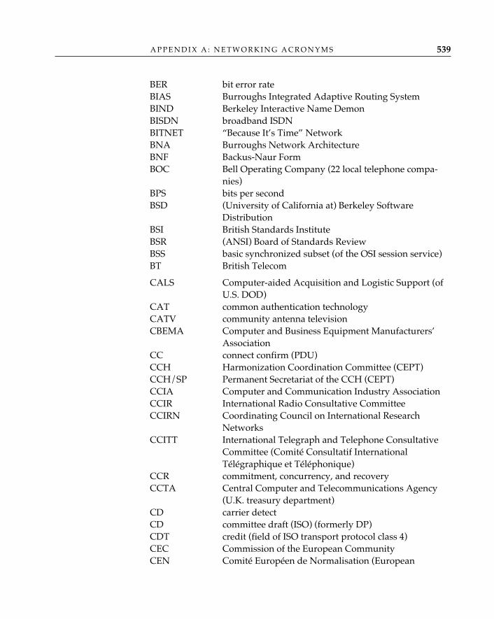
BER bit error rateBIAS Burroughs Integrated Adaptive Routing SystemBIND Berkeley Interactive Name DemonBISDN broadband ISDNBITNET “Because It’s Time” NetworkBNA Burroughs Network ArchitectureBNF Backus-Naur FormBOC Bell Operating Company (22 local telephone compa-
nies)BPS bits per secondBSD (University of California at) Berkeley Software
DistributionBSI British Standards InstituteBSR (ANSI) Board of Standards ReviewBSS basic synchronized subset (of the OSI session service)BT British Telecom
CALS Computer-aided Acquisition and Logistic Support (ofU.S. DOD)
CAT common authentication technologyCATV community antenna televisionCBEMA Computer and Business Equipment Manufacturers’
AssociationCC connect confirm (PDU)CCH Harmonization Coordination Committee (CEPT)CCH/SP Permanent Secretariat of the CCH (CEPT)CCIA Computer and Communication Industry AssociationCCIR International Radio Consultative CommitteeCCIRN Coordinating Council on International Research
NetworksCCITT International Telegraph and Telephone Consultative
Committee (Comité Consultatif InternationalTélégraphique et Téléphonique)
CCR commitment, concurrency, and recoveryCCTA Central Computer and Telecommunications Agency
(U.K. treasury department)CD carrier detectCD committee draft (ISO) (formerly DP)CDT credit (field of ISO transport protocol class 4)CEC Commission of the European CommunityCEN Comité Européen de Normalisation (European
A P P E N D I X A : N E T W O R K I N G A C R O N Y M S 539
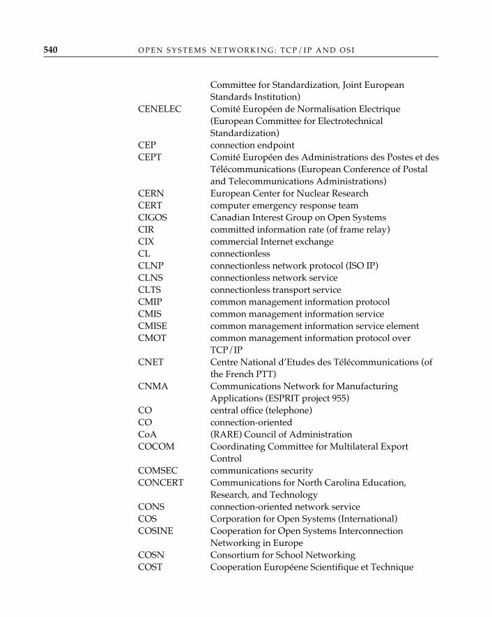
Committee for Standardization, Joint EuropeanStandards Institution)
CENELEC Comité Européen de Normalisation Electrique(European Committee for ElectrotechnicalStandardization)
CEP connection endpointCEPT Comité Européen des Administrations des Postes et des
Télécommunications (European Conference of Postaland Telecommunications Administrations)
CERN European Center for Nuclear ResearchCERT computer emergency response teamCIGOS Canadian Interest Group on Open SystemsCIR committed information rate (of frame relay)CIX commercial Internet exchangeCL connectionlessCLNP connectionless network protocol (ISO IP)CLNS connectionless network serviceCLTS connectionless transport serviceCMIP common management information protocolCMIS common management information serviceCMISE common management information service elementCMOT common management information protocol over
TCP/IPCNET Centre National d’Etudes des Télécommunications (of
the French PTT)CNMA Communications Network for Manufacturing
Applications (ESPRIT project 955)CO central office (telephone)CO connection-orientedCoA (RARE) Council of AdministrationCOCOM Coordinating Committee for Multilateral Export
ControlCOMSEC communications securityCONCERT Communications for North Carolina Education,
Research, and TechnologyCONS connection-oriented network serviceCOS Corporation for Open Systems (International)COSINE Cooperation for Open Systems Interconnection
Networking in EuropeCOSN Consortium for School NetworkingCOST Cooperation Européene Scientifique et Technique
O P E N S Y S T E M S N E T W O R K I N G : T C P / I P A N D O S I540
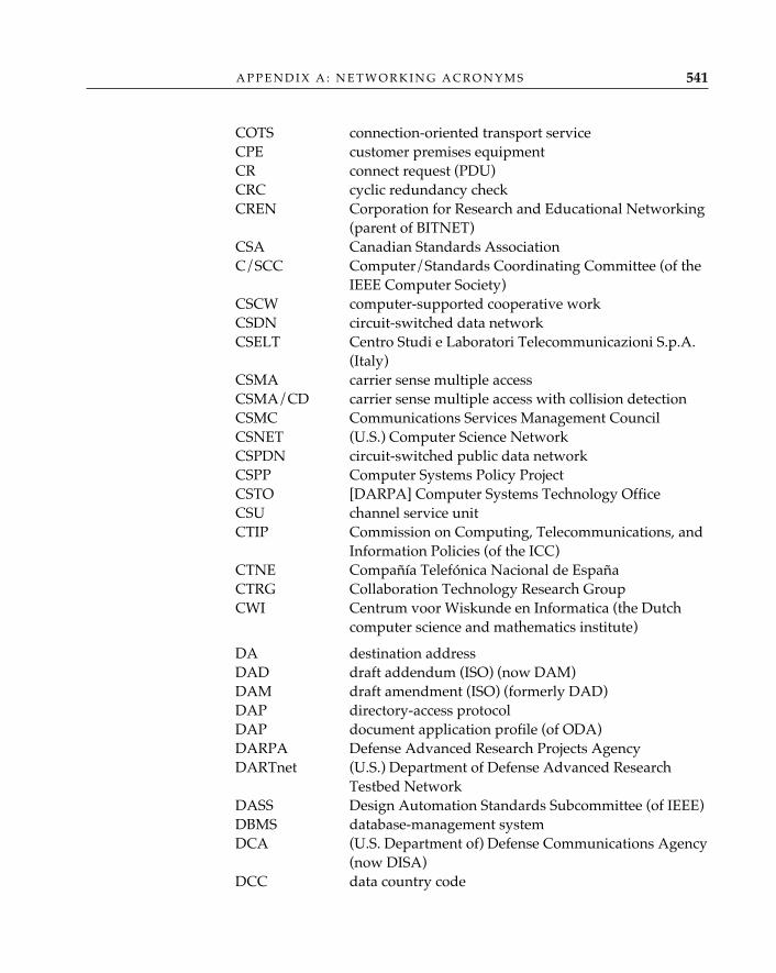
COTS connection-oriented transport serviceCPE customer premises equipmentCR connect request (PDU)CRC cyclic redundancy checkCREN Corporation for Research and Educational Networking
(parent of BITNET)CSA Canadian Standards AssociationC/SCC Computer/Standards Coordinating Committee (of the
IEEE Computer Society)CSCW computer-supported cooperative workCSDN circuit-switched data networkCSELT Centro Studi e Laboratori Telecommunicazioni S.p.A.
(Italy)CSMA carrier sense multiple accessCSMA/CD carrier sense multiple access with collision detectionCSMC Communications Services Management CouncilCSNET (U.S.) Computer Science NetworkCSPDN circuit-switched public data networkCSPP Computer Systems Policy ProjectCSTO [DARPA] Computer Systems Technology OfficeCSU channel service unitCTIP Commission on Computing, Telecommunications, and
Information Policies (of the ICC)CTNE Compañía Telefónica Nacional de EspañaCTRG Collaboration Technology Research GroupCWI Centrum voor Wiskunde en Informatica (the Dutch
computer science and mathematics institute)
DA destination addressDAD draft addendum (ISO) (now DAM)DAM draft amendment (ISO) (formerly DAD)DAP directory-access protocolDAP document application profile (of ODA)DARPA Defense Advanced Research Projects AgencyDARTnet (U.S.) Department of Defense Advanced Research
Testbed NetworkDASS Design Automation Standards Subcommittee (of IEEE)DBMS database-management systemDCA (U.S. Department of) Defense Communications Agency
(now DISA)DCC data country code
A P P E N D I X A : N E T W O R K I N G A C R O N Y M S 541

DCE data circuit-terminating equipmentDCE distributed computing environment (OSF)DCEC (U.S. Department of) Defense Communications
Engineering CenterDCS defined-context set (in presentation)DDN Defense Data NetworkDDP distributed data processingDDS digital data serviceDES data-encryption standard (FIPS PUB 46 1-15-77)DESIRE Directory of European Information Security Standards
RequirementsDFN Deutsches Forschungsnetz (German research network)DIB directory information baseDIGI Deutsche Interessengemeinschaft Internet (German
Internet users’ group)DIN Deutsches Institut für NormungDIS draft international standard (ISO)DISA (U.S. Department of) Defense Information Systems
Agency (formerly DCA)DISERF Data Interchange Standards Education and Research
FoundationDISN (U.S. Department of) Defense Information Systems
NetworkDISP draft international standardized profileDIT directory information treeDLCI data-link connection identifier (of LAP-D)DME distributed management environmentDMZ demilitarized zoneDN distinguished name (of X.500 directory service)DNA Digital Network Architecture (DEC)DNIC data network identification codeDNS domain name systemDOD (U.S.) Department of DefenseDOE (U.S.) Department of EnergyDP draft proposal (ISO) (now CD)dpANS draft proposed American national standardDQDB distributed queue dual bus (802.6 MAN)DS directory serviceDS0 digital signal level 0 (64 Kbps)DS1 digital signal level 1 (1.544 Mbps)DS3 digital signal level 3 (44.736 Mbps)
O P E N S Y S T E M S N E T W O R K I N G : T C P / I P A N D O S I542
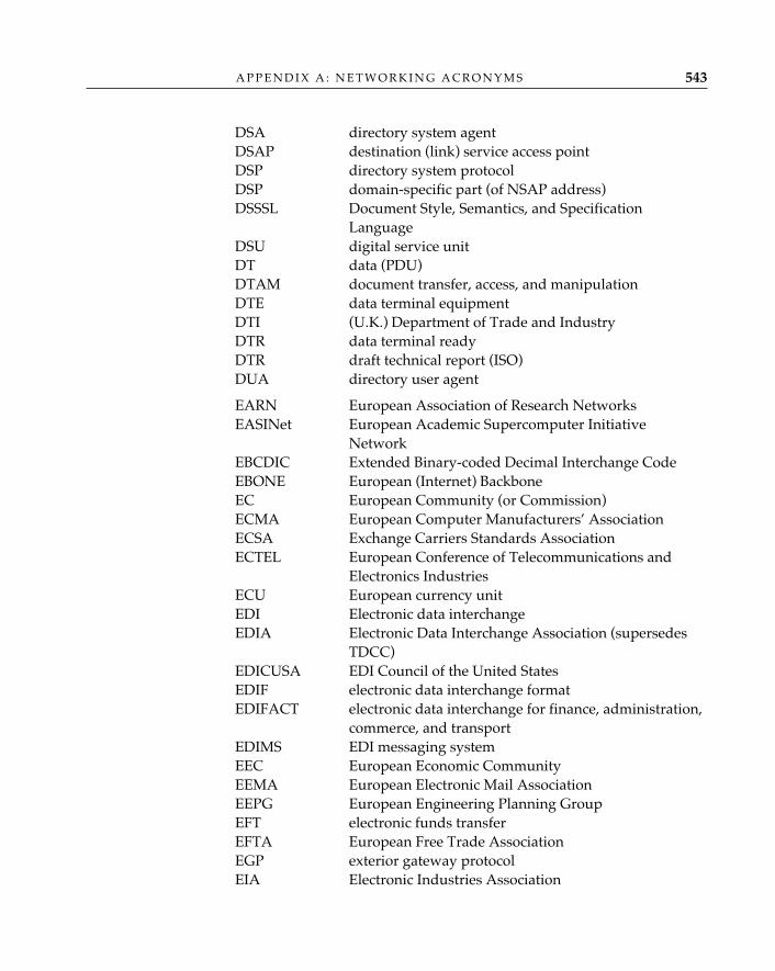
DSA directory system agentDSAP destination (link) service access pointDSP directory system protocolDSP domain-specific part (of NSAP address)DSSSL Document Style, Semantics, and Specification
LanguageDSU digital service unitDT data (PDU)DTAM document transfer, access, and manipulationDTE data terminal equipmentDTI (U.K.) Department of Trade and IndustryDTR data terminal readyDTR draft technical report (ISO)DUA directory user agent
EARN European Association of Research NetworksEASINet European Academic Supercomputer Initiative
NetworkEBCDIC Extended Binary-coded Decimal Interchange CodeEBONE European (Internet) BackboneEC European Community (or Commission)ECMA European Computer Manufacturers’ AssociationECSA Exchange Carriers Standards AssociationECTEL European Conference of Telecommunications and
Electronics IndustriesECU European currency unitEDI Electronic data interchangeEDIA Electronic Data Interchange Association (supersedes
TDCC)EDICUSA EDI Council of the United StatesEDIF electronic data interchange formatEDIFACT electronic data interchange for finance, administration,
commerce, and transportEDIMS EDI messaging systemEEC European Economic CommunityEEMA European Electronic Mail AssociationEEPG European Engineering Planning GroupEFT electronic funds transferEFTA European Free Trade AssociationEGP exterior gateway protocolEIA Electronic Industries Association
A P P E N D I X A : N E T W O R K I N G A C R O N Y M S 543
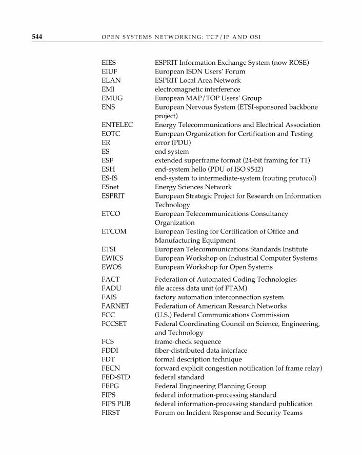
EIES ESPRIT Information Exchange System (now ROSE)EIUF European ISDN Users’ ForumELAN ESPRIT Local Area NetworkEMI electromagnetic interferenceEMUG European MAP/TOP Users’ GroupENS European Nervous System (ETSI-sponsored backbone
project)ENTELEC Energy Telecommunications and Electrical AssociationEOTC European Organization for Certification and TestingER error (PDU)ES end systemESF extended superframe format (24-bit framing for T1)ESH end-system hello (PDU of ISO 9542)ES-IS end-system to intermediate-system (routing protocol)ESnet Energy Sciences NetworkESPRIT European Strategic Project for Research on Information
TechnologyETCO European Telecommunications Consultancy
OrganizationETCOM European Testing for Certification of Office and
Manufacturing EquipmentETSI European Telecommunications Standards InstituteEWICS European Workshop on Industrial Computer SystemsEWOS European Workshop for Open Systems
FACT Federation of Automated Coding TechnologiesFADU file access data unit (of FTAM)FAIS factory automation interconnection systemFARNET Federation of American Research NetworksFCC (U.S.) Federal Communications CommissionFCCSET Federal Coordinating Council on Science, Engineering,
and TechnologyFCS frame-check sequenceFDDI fiber-distributed data interfaceFDT formal description techniqueFECN forward explicit congestion notification (of frame relay)FED-STD federal standardFEPG Federal Engineering Planning GroupFIPS federal information-processing standardFIPS PUB federal information-processing standard publicationFIRST Forum on Incident Response and Security Teams
O P E N S Y S T E M S N E T W O R K I N G : T C P / I P A N D O S I544
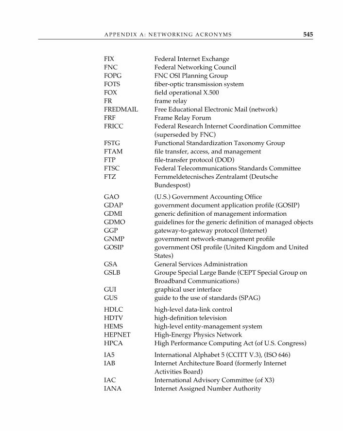
FIX Federal Internet ExchangeFNC Federal Networking CouncilFOPG FNC OSI Planning GroupFOTS fiber-optic transmission systemFOX field operational X.500FR frame relayFREDMAIL Free Educational Electronic Mail (network)FRF Frame Relay ForumFRICC Federal Research Internet Coordination Committee
(superseded by FNC)FSTG Functional Standardization Taxonomy GroupFTAM file transfer, access, and managementFTP file-transfer protocol (DOD)FTSC Federal Telecommunications Standards CommitteeFTZ Fernmeldetecnisches Zentralamt (Deutsche
Bundespost)
GAO (U.S.) Government Accounting OfficeGDAP government document application profile (GOSIP)GDMI generic definition of management informationGDMO guidelines for the generic definition of managed objectsGGP gateway-to-gateway protocol (Internet)GNMP government network-management profileGOSIP government OSI profile (United Kingdom and United
States)GSA General Services AdministrationGSLB Groupe Special Large Bande (CEPT Special Group on
Broadband Communications)GUI graphical user interfaceGUS guide to the use of standards (SPAG)
HDLC high-level data-link controlHDTV high-definition televisionHEMS high-level entity-management systemHEPNET High-Energy Physics NetworkHPCA High Performance Computing Act (of U.S. Congress)
IA5 International Alphabet 5 (CCITT V.3), (ISO 646)IAB Internet Architecture Board (formerly Internet
Activities Board)IAC International Advisory Committee (of X3)IANA Internet Assigned Number Authority
A P P E N D I X A : N E T W O R K I N G A C R O N Y M S 545
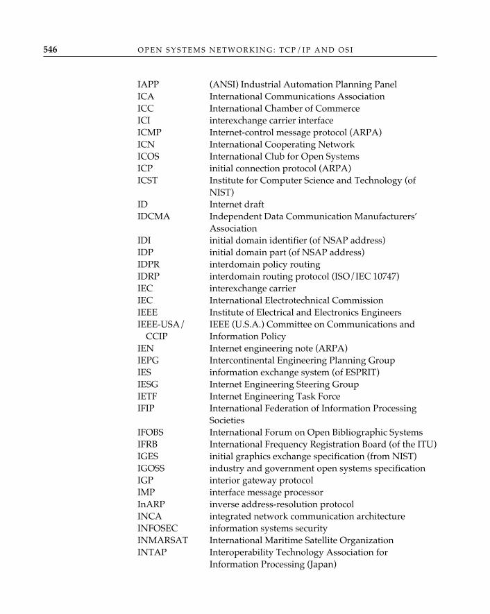
IAPP (ANSI) Industrial Automation Planning PanelICA International Communications AssociationICC International Chamber of CommerceICI interexchange carrier interfaceICMP Internet-control message protocol (ARPA)ICN International Cooperating NetworkICOS International Club for Open SystemsICP initial connection protocol (ARPA)ICST Institute for Computer Science and Technology (of
NIST)ID Internet draftIDCMA Independent Data Communication Manufacturers’
AssociationIDI initial domain identifier (of NSAP address)IDP initial domain part (of NSAP address)IDPR interdomain policy routingIDRP interdomain routing protocol (ISO/IEC 10747)IEC interexchange carrierIEC International Electrotechnical CommissionIEEE Institute of Electrical and Electronics EngineersIEEE-USA/ IEEE (U.S.A.) Committee on Communications and
CCIP Information PolicyIEN Internet engineering note (ARPA)IEPG Intercontinental Engineering Planning GroupIES information exchange system (of ESPRIT)IESG Internet Engineering Steering GroupIETF Internet Engineering Task ForceIFIP International Federation of Information Processing
SocietiesIFOBS International Forum on Open Bibliographic SystemsIFRB International Frequency Registration Board (of the ITU)IGES initial graphics exchange specification (from NIST)IGOSS industry and government open systems specificationIGP interior gateway protocolIMP interface message processorInARP inverse address-resolution protocolINCA integrated network communication architectureINFOSEC information systems securityINMARSAT International Maritime Satellite OrganizationINTAP Interoperability Technology Association for
Information Processing (Japan)
O P E N S Y S T E M S N E T W O R K I N G : T C P / I P A N D O S I546
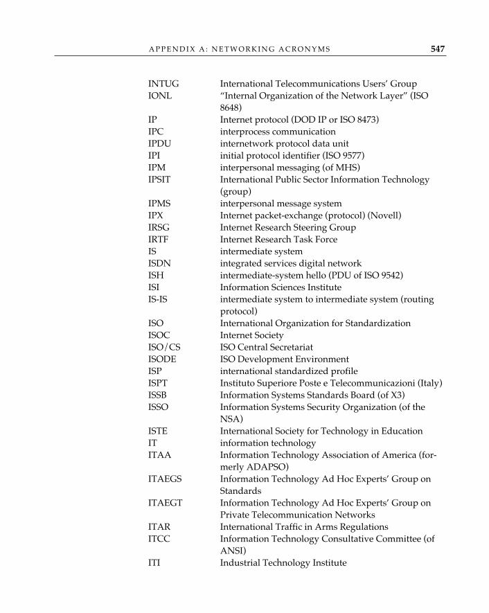
INTUG International Telecommunications Users’ GroupIONL “Internal Organization of the Network Layer” (ISO
8648)IP Internet protocol (DOD IP or ISO 8473)IPC interprocess communicationIPDU internetwork protocol data unitIPI initial protocol identifier (ISO 9577)IPM interpersonal messaging (of MHS)IPSIT International Public Sector Information Technology
(group)IPMS interpersonal message systemIPX Internet packet-exchange (protocol) (Novell)IRSG Internet Research Steering GroupIRTF Internet Research Task ForceIS intermediate systemISDN integrated services digital networkISH intermediate-system hello (PDU of ISO 9542)ISI Information Sciences InstituteIS-IS intermediate system to intermediate system (routing
protocol)ISO International Organization for StandardizationISOC Internet SocietyISO/CS ISO Central SecretariatISODE ISO Development EnvironmentISP international standardized profileISPT Instituto Superiore Poste e Telecommunicazioni (Italy)ISSB Information Systems Standards Board (of X3)ISSO Information Systems Security Organization (of the
NSA)ISTE International Society for Technology in EducationIT information technologyITAA Information Technology Association of America (for-
merly ADAPSO)ITAEGS Information Technology Ad Hoc Experts’ Group on
StandardsITAEGT Information Technology Ad Hoc Experts’ Group on
Private Telecommunication NetworksITAR International Traffic in Arms RegulationsITCC Information Technology Consultative Committee (of
ANSI)ITI Industrial Technology Institute
A P P E N D I X A : N E T W O R K I N G A C R O N Y M S 547
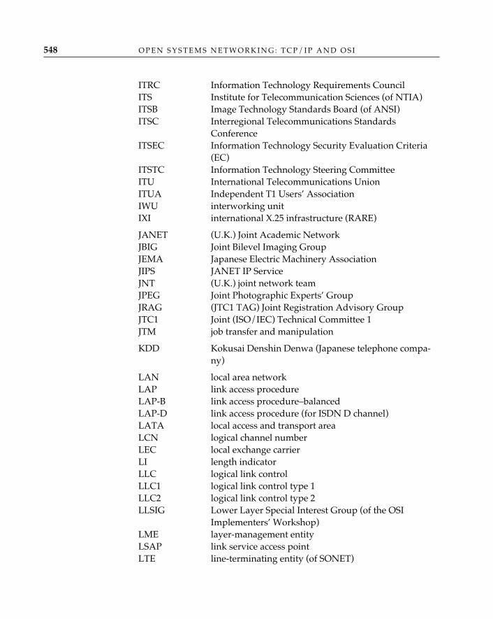
ITRC Information Technology Requirements CouncilITS Institute for Telecommunication Sciences (of NTIA)ITSB Image Technology Standards Board (of ANSI)ITSC Interregional Telecommunications Standards
ConferenceITSEC Information Technology Security Evaluation Criteria
(EC)ITSTC Information Technology Steering CommitteeITU International Telecommunications UnionITUA Independent T1 Users’ AssociationIWU interworking unitIXI international X.25 infrastructure (RARE)
JANET (U.K.) Joint Academic NetworkJBIG Joint Bilevel Imaging GroupJEMA Japanese Electric Machinery AssociationJIPS JANET IP ServiceJNT (U.K.) joint network teamJPEG Joint Photographic Experts’ GroupJRAG (JTC1 TAG) Joint Registration Advisory GroupJTC1 Joint (ISO/IEC) Technical Committee 1JTM job transfer and manipulation
KDD Kokusai Denshin Denwa (Japanese telephone compa-ny)
LAN local area networkLAP link access procedureLAP-B link access procedure–balancedLAP-D link access procedure (for ISDN D channel)LATA local access and transport areaLCN logical channel numberLEC local exchange carrierLI length indicatorLLC logical link controlLLC1 logical link control type 1LLC2 logical link control type 2LLSIG Lower Layer Special Interest Group (of the OSI
Implementers’ Workshop)LME layer-management entityLSAP link service access pointLTE line-terminating entity (of SONET)
O P E N S Y S T E M S N E T W O R K I N G : T C P / I P A N D O S I548
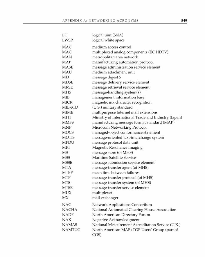
LU logical unit (SNA)LWSP logical white space
MAC medium access controlMAC multiplexed analog components (EC HDTV)MAN metropolitan area networkMAP manufacturing automation protocolMASE message administration service elementMAU medium attachment unitMD message digest 5MDSE message delivery service elementMRSE message retrieval service elementMHS message-handling system(s)MIB management information baseMICR magnetic ink character recognitionMIL-STD (U.S.) military standardMIME multipurpose Internet mail extensionsMITI Ministry of International Trade and Industry (Japan)MMFS manufacturing message format standard (MAP)MNP Microcom Networking ProtocolMOCS managed-object conformance statementMOTIS message-oriented text-interchange systemMPDU message protocol data unitMRI Magnetic Resonance ImagingMS message store (of MHS)MSS Maritime Satellite ServiceMSSE message submission service elementMTA message-transfer agent (of MHS)MTBF mean time between failuresMTP message-transfer protocol (of MHS)MTS message-transfer system (of MHS)MTSE message-transfer service elementMUX multiplexerMX mail exchanger
NAC Network Applications ConsortiumNACHA National Automated Clearing House AssociationNADF North American Directory ForumNAK Negative AcknowledgmentNAMAS National Measurement Accreditation Service (U.K.)NAMTUG North American MAP/TOP Users’ Group (part of
COS)
A P P E N D I X A : N E T W O R K I N G A C R O N Y M S 549
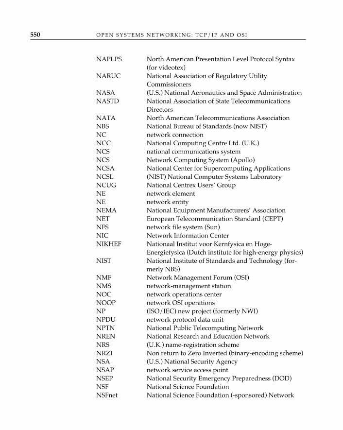
NAPLPS North American Presentation Level Protocol Syntax(for videotex)
NARUC National Association of Regulatory UtilityCommissioners
NASA (U.S.) National Aeronautics and Space AdministrationNASTD National Association of State Telecommunications
DirectorsNATA North American Telecommunications AssociationNBS National Bureau of Standards (now NIST)NC network connectionNCC National Computing Centre Ltd. (U.K.)NCS national communications systemNCS Network Computing System (Apollo)NCSA National Center for Supercomputing ApplicationsNCSL (NIST) National Computer Systems LaboratoryNCUG National Centrex Users’ GroupNE network elementNE network entityNEMA National Equipment Manufacturers’ AssociationNET European Telecommunication Standard (CEPT)NFS network file system (Sun)NIC Network Information CenterNIKHEF Nationaal Institut voor Kernfysica en Hoge-
Energiefysica (Dutch institute for high-energy physics)NIST National Institute of Standards and Technology (for-
merly NBS)NMF Network Management Forum (OSI)NMS network-management stationNOC network operations centerNOOP network OSI operationsNP (ISO/IEC) new project (formerly NWI)NPDU network protocol data unitNPTN National Public Telecomputing NetworkNREN National Research and Education NetworkNRS (U.K.) name-registration schemeNRZI Non return to Zero Inverted (binary-encoding scheme)NSA (U.S.) National Security AgencyNSAP network service access pointNSEP National Security Emergency Preparedness (DOD)NSF National Science FoundationNSFnet National Science Foundation (-sponsored) Network
O P E N S Y S T E M S N E T W O R K I N G : T C P / I P A N D O S I550
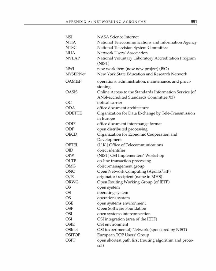
NSI NASA Science InternetNTIA National Telecommunications and Information AgencyNTSC National Television System CommitteeNUA Network Users’ AssociationNVLAP National Voluntary Laboratory Accreditation Program
(NIST)NWI new work item (now new project) (ISO)NYSERNet New York State Education and Research Network
OAM&P operations, administration, maintenance, and provi-sioning
OASIS Online Access to the Standards Information Service (ofANSI-accredited Standards Committee X3)
OC optical carrierODA office document architectureODETTE Organization for Data Exchange by Tele-Transmission
in EuropeODIF office document interchange formatODP open distributed processingOECD Organization for Economic Cooperation and
DevelopmentOFTEL (U.K.) Office of TelecommunicationsOID object identifierOIW (NIST) OSI Implementers’ WorkshopOLTP on-line transaction processingOMG object-management groupONC Open Network Computing (Apollo/HP)O/R originator/recipient (name in MHS)ORWG Open Routing Working Group (of IETF)OS open systemOS operating systemOS operations systemOSE open systems environmentOSF Open Software FoundationOSI open systems interconnectionOSI OSI integration (area of the IETF)OSIE OSI environmentOSInet OSI (experimental) Network (sponsored by NIST)OSITOP European TOP Users’ GroupOSPF open shortest path first (routing algorithm and proto-
col)
A P P E N D I X A : N E T W O R K I N G A C R O N Y M S 551
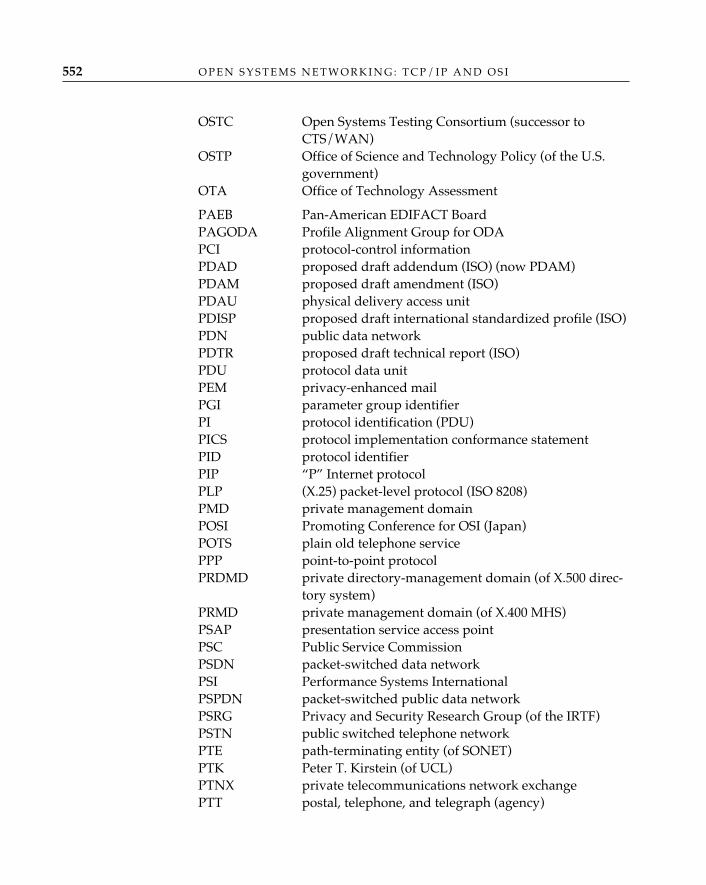
OSTC Open Systems Testing Consortium (successor toCTS/WAN)
OSTP Office of Science and Technology Policy (of the U.S.government)
OTA Office of Technology Assessment
PAEB Pan-American EDIFACT BoardPAGODA Profile Alignment Group for ODAPCI protocol-control informationPDAD proposed draft addendum (ISO) (now PDAM)PDAM proposed draft amendment (ISO)PDAU physical delivery access unitPDISP proposed draft international standardized profile (ISO)PDN public data networkPDTR proposed draft technical report (ISO)PDU protocol data unitPEM privacy-enhanced mailPGI parameter group identifierPI protocol identification (PDU)PICS protocol implementation conformance statementPID protocol identifierPIP “P” Internet protocolPLP (X.25) packet-level protocol (ISO 8208)PMD private management domainPOSI Promoting Conference for OSI (Japan)POTS plain old telephone servicePPP point-to-point protocolPRDMD private directory-management domain (of X.500 direc-
tory system)PRMD private management domain (of X.400 MHS)PSAP presentation service access pointPSC Public Service CommissionPSDN packet-switched data networkPSI Performance Systems InternationalPSPDN packet-switched public data networkPSRG Privacy and Security Research Group (of the IRTF)PSTN public switched telephone networkPTE path-terminating entity (of SONET)PTK Peter T. Kirstein (of UCL)PTNX private telecommunications network exchangePTT postal, telephone, and telegraph (agency)
O P E N S Y S T E M S N E T W O R K I N G : T C P / I P A N D O S I552
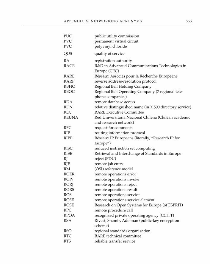
PUC public utility commissionPVC permanent virtual circuitPVC polyvinyl chloride
QOS quality of service
RA registration authorityRACE R&D in Advanced Communications Technologies in
Europe (CEC)RARE Réseaux Associés pour la Récherche EuropéeneRARP reverse address-resolution protocolRBHC Regional Bell Holding CompanyRBOC Regional Bell Operating Company (7 regional tele-
phone companies)RDA remote database accessRDN relative distinguished name (in X.500 directory service)REC RARE Executive CommitteeREUNA Red Universitaria Nacional Chilena (Chilean academic
and research network)RFC request for commentsRIP routing information protocolRIPE Réseaux IP Européens (literally, “Research IP for
Europe”)RISC reduced instruction set computingRISE Retrieval and Interchange of Standards in EuropeRJ reject (PDU)RJE remote job entryRM (OSI) reference modelROER remote operations errorROIV remote operations invokeRORJ remote operations rejectRORS remote operations resultROS remote operations serviceROSE remote operations service elementROSE Research on Open Systems for Europe (of ESPRIT)RPC remote procedure callRPOA recognized private operating agency (CCITT)RSA Rivest, Shamir, Adelman (public-key encryption
scheme)RSO regional standards organizationRTC RARE technical committeeRTS reliable transfer service
A P P E N D I X A : N E T W O R K I N G A C R O N Y M S 553
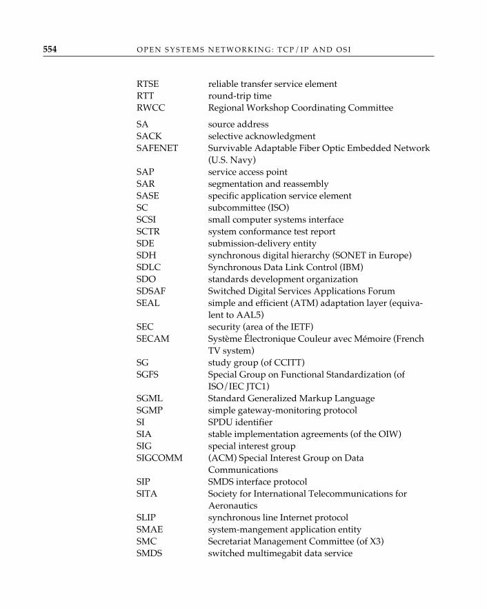
RTSE reliable transfer service elementRTT round-trip timeRWCC Regional Workshop Coordinating Committee
SA source addressSACK selective acknowledgmentSAFENET Survivable Adaptable Fiber Optic Embedded Network
(U.S. Navy)SAP service access pointSAR segmentation and reassemblySASE specific application service elementSC subcommittee (ISO)SCSI small computer systems interfaceSCTR system conformance test reportSDE submission-delivery entitySDH synchronous digital hierarchy (SONET in Europe)SDLC Synchronous Data Link Control (IBM)SDO standards development organizationSDSAF Switched Digital Services Applications ForumSEAL simple and efficient (ATM) adaptation layer (equiva-
lent to AAL5)SEC security (area of the IETF)SECAM Système Électronique Couleur avec Mémoire (French
TV system)SG study group (of CCITT)SGFS Special Group on Functional Standardization (of
ISO/IEC JTC1)SGML Standard Generalized Markup LanguageSGMP simple gateway-monitoring protocolSI SPDU identifierSIA stable implementation agreements (of the OIW)SIG special interest groupSIGCOMM (ACM) Special Interest Group on Data
CommunicationsSIP SMDS interface protocolSITA Society for International Telecommunications for
AeronauticsSLIP synchronous line Internet protocolSMAE system-mangement application entitySMC Secretariat Management Committee (of X3)SMDS switched multimegabit data service
O P E N S Y S T E M S N E T W O R K I N G : T C P / I P A N D O S I554
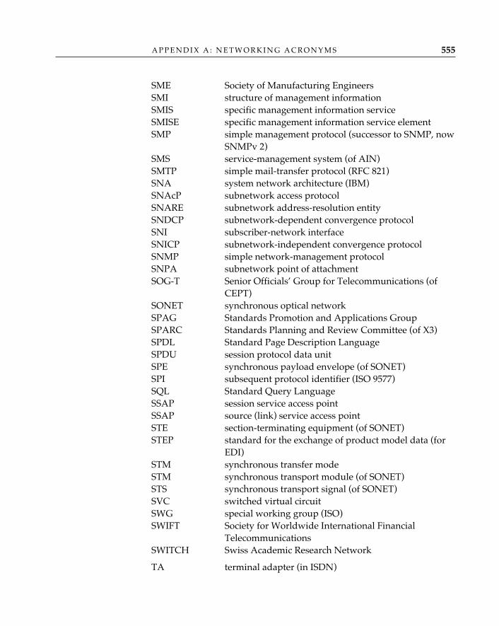
SME Society of Manufacturing EngineersSMI structure of management informationSMIS specific management information serviceSMISE specific management information service elementSMP simple management protocol (successor to SNMP, now
SNMPv 2)SMS service-management system (of AIN)SMTP simple mail-transfer protocol (RFC 821)SNA system network architecture (IBM)SNAcP subnetwork access protocolSNARE subnetwork address-resolution entitySNDCP subnetwork-dependent convergence protocolSNI subscriber-network interfaceSNICP subnetwork-independent convergence protocolSNMP simple network-management protocolSNPA subnetwork point of attachmentSOG-T Senior Officials’ Group for Telecommunications (of
CEPT)SONET synchronous optical networkSPAG Standards Promotion and Applications GroupSPARC Standards Planning and Review Committee (of X3)SPDL Standard Page Description LanguageSPDU session protocol data unitSPE synchronous payload envelope (of SONET)SPI subsequent protocol identifier (ISO 9577)SQL Standard Query LanguageSSAP session service access pointSSAP source (link) service access pointSTE section-terminating equipment (of SONET)STEP standard for the exchange of product model data (for
EDI)STM synchronous transfer modeSTM synchronous transport module (of SONET)STS synchronous transport signal (of SONET)SVC switched virtual circuitSWG special working group (ISO)SWIFT Society for Worldwide International Financial
TelecommunicationsSWITCH Swiss Academic Research Network
TA terminal adapter (in ISDN)
A P P E N D I X A : N E T W O R K I N G A C R O N Y M S 555
TAC terminal access controllerTAG technical advisory groupTC technical committeeTC transport connectionTCP transmission-control protocolTCSEC Trusted Computer System Evaluation Criteria (of the
U.S. Department of Defense)TDCC Transportation Data Coordinating Committee (super-
seded by EDIA)TDM time division multiplexingTDMA time division multiple accessTE terminal equipmentTELNET Internet virtual terminal protocolTERC Technology Education Research CenterTERC Telecommunications Equipment Remarketing CouncilTFTP trivial file-transfer protocolTG task groupTHEnet Texas Higher Education NetworkTIP terminal interface processorTLI transport-layer interfaceTLMA telematic access unitTLV type-length-value (format for parameter encoding in
PDUs)TMP test-management protocolTNIC transit network identification codeTOP technical and office protocolsTOS type of service (routing)TP transaction processingTP transport protocolTP0, TP1, etc. transport protocol (ISO/IEC 8073) class 0, class 1, etc.TPDU transport protocol data unitTPI transport protocol interface (streams) TR (Bellcore) technical referenceTR technical report (ISO)TRAC Technical Recommendation Application Committee (of
CEPT)TS transport serviceTSAP transport service access pointTTC Telecommunications Technology Council (of the
Japanese Ministry of Posts and Telecommunications)TTCN Tree and Tabular Combined Notation
O P E N S Y S T E M S N E T W O R K I N G : T C P / I P A N D O S I556
TT-CNMA Testing Technology for Communications Network forManufacturing Applications (ESPRIT II project)
TTL time to liveTWA two-way alternate (in session)TWS two-way simultaneous (in session)
UA user agent (in MHS)UAOS User Alliance for Open SystemsUCL University College, LondonUCS uniform communications standardUD UnitData (PDU)UDP user datagram protocol (ARPA)UI UNIX InternationalUI unnumbered information (frame)UKRA U.K. (United Kingdom) registration authorityUL Underwriters’ LaboratoriesULA upper-layer architectureULCC University of London Computing CentreULP upper-layer processUNI user-network interface (of ISDN)UPS uninterruptable power supplyUPT universal personal telecommunicationsUSITA United States Independent Telephone AssociationUSNC United States National CommitteeUSO UNIX software operationUSRA Universities Space Research AssociationUSV user services (area of the IETF)UTC universal time coordinateUUCP UNIX-to-UNIX copy
VADS value-added data servicesVAN value-added networkVC virtual circuitVCI virtual channel identifier (of SONET)VMTP versatile message transaction protocolVPI virtual path identifier (of SONET)VPN virtual private networkVT virtual terminalVT virtual tributary (of SONET)VTP virtual terminal protocol
WAIS wide area information service (or server)
A P P E N D I X A : N E T W O R K I N G A C R O N Y M S 557
WAN wide area networkWATS wide area telephone serviceWD working draftWG working groupWIN Wissenschaftsnetz (German scientific network)WINCS WWMCCS Intercomputer Network Communication
SubsystemWINDO Wide Information Network for Data Online (of U.S.
Government Printing Office)WINS warehouse information network standardWP working party (of CCITT study group)WWW World Wide WebWWMCCS Worldwide Military Command and Control System
(DOD)
XALS extended appliation-layer structureXDR external data representation (Sun)XID exchange identification (PDU)XMH X mail handlerXNS Xerox Network SystemsXPG X.400 Promotion GroupXPG X/Open Portability GuideXTP express transfer protocol
Readers will encounter many more acronyms and abbreviations inthis list than the authors dared use in the text. These are provided as ahedge against the inevitable; if you read further about open systems net-working, you will eventually encounter all of these acronyms, and manymore.
O P E N S Y S T E M S N E T W O R K I N G : T C P / I P A N D O S I558
How and Where to Obtain Useful InformationNo book, no matter how large, could possibly contain all the informationthat is available about open systems networking; even a casual interest inthe subject will sooner or later give rise to questions that either are notanswered in this book or are answered without the additional detail orcontext that the reader’s interest requires. Fortunately, the world of opensystems networking is, for the most part, genuinely “open” with respectto access to documentation; with few exceptions, any information aboutTCP/IP or OSI that is not found in this book can be obtained with littledifficulty from one of the sources listed in this appendix.
At the time this is being written, it is still the case that the primarysources of information about the TCP/IP architecture and protocol suiteare available at essentially no cost1 to anyone with any kind of access tothe Internet (including, for example, anyone with a commercial electronicmail account with MCI or CompuServe,2 in addition to those who arefortunate enough to have a direct connection to the Internet), but the pri-mary OSI sources—the ISO/IEC and CCITT standards—are not. Thestandards-development activities of the Internet are almost entirely sub-sidized by the United States government and (very recently) by the In-ternet Society; the standards-development activities of ISO/IEC and
B SOURCES
559
1. “Essentially” because even though there is no explicit charge for retrieving docu-ments by file transfer or electronic mail over the Internet, someone, somewhere is payingfor the network access that makes it possible.2. See the discussion of mail gateways later in this appendix for a list of some of theways in which electronic-mail access to Internet information can be obtained when nodirect Internet connection is available.
CCITT (and their associated national standards bodies in individualmember countries), on the other hand, are funded in large part by thesale of (printed) standards. This situation is likely to change soon, soreaders are advised to ask about alternative sources (particularly on-linearchives) for OSI standards before buying them.
Many people in the Internet community use the fact thatInternet documents are “free” and OSI documents are not as a
prime example of the superiority of the Internet way of doing things, notwith-standing the behind-the-scenes government largess that makes it possible.However, this is more than just a matter of smug satisfaction for members of onegroup at the other’s expense; the difficulty and expense of obtaining the OSIstandards and related documentation, particularly in light of the apparent easeand freedom with which similar documentation for the Internet standards can beobtained, has effectively blocked the widespread acceptance of OSI as the basis foropen systems networking. From a marketing perspective, the way in which theOSI standards community has packaged and promoted its products could nothave been better designed to ensure the success of the alternative (TCP/IP).TCP/IP information is free and is available (in electronic form, instantly, “overthe net”) everywhere; OSI information is absurdly expensive and can beobtained (by postal mail, on paper) only from a very small number of authorizedsources. If the success of a standards-development activity is the extent to whichits results (standards) are actually used, then it is not hard to conclude that inthe case of OSI, the ISO/IEC and CCITT standards bodies have actively—and itappears, successfully—labored mightily to ensure their own failure.
Information about TCP/IP and the InternetIn order to tap into the vast reservoir of information about the Internetand its technology3 that is available “on-line,” one must first figure out away to be “on-line” oneself. This can be accomplished in one of twoways: by connecting to the Internet directly or by connecting indirectlythrough an electronic-mail gateway.4
✧AHA✧
O P E N S Y S T E M S N E T W O R K I N G : T C P / I P A N D O S I560
3. There is also, of course, a wealth of information available through the Internet aboutthings other than the Internet itself; except for those people for whom the Internet itself isthe primary subject of interest, these other information resources are naturally much moreimportant and are ultimately the reason for having an Internet in the first place. They arenot, however, the point of this appendix.4. A wealth of additional information about the way in which networks around theworld are interconnected, and how to navigate the maze of different address formats and
Direct connection simply means that one’s computer system—per-sonal computer, workstation, time-sharing computer, etc.—is equippedwith the protocols (usually, TCP/IP) necessary to exchange informationdirectly with similarly equipped systems and that the local network towhich one’s system is attached (local area network, dial-up access net-work, etc.) is itself attached by communication links to other networks aspart of the worldwide Internet “network of networks.” If this is the case,and local policy constraints do not prohibit doing so,5 one can use theTCP/IP file-transfer protocol (FTP) to obtain files directly from sites thatmaintain “anonymous FTP” archives—“anonymous” because they allowanyone to log in to the site with the user name “anonymous” and anypassword.6 The way in which one uses FTP to do this varies from onesystem and software package to another; one must check with the localsystem or network administrator.
The information contained in many (but not all) Internet archivescan also be obtained by users who do not have a direct connection to theInternet but do have some sort of electronic-mail capability (such as MCI-mail, CompuServe, or BITNET). Mail gateways between the Internet andmany electronic-mail systems (including virtually every commercial mailsystem) allow messages to be sent from a system that is not directly con-nected to the Internet to an Internet archive and for that archive (if it isequipped to do so, as many are) to send back, in reply, one or more filesthat were named in the message. The two main drawbacks are that (1)one must know precisely which file or files one wants (so as to be able togive the precise file name in the request message), and (2) many mailgateways impose a limit on the size of mail messages that may passthrough them, which effectively denies access to files above a certainsize. Commonly used mail gateways include the BITNET/Internet gate-way at cunyvm.cuny.edu , the UUCP/Internet gateway atuunet.uu.net, and the MCImail gateway at mcimail.com.
Internet requests for comments (RFCs) and the working documents ofInternet Engineering Task Force (IETF) working groups (Internet drafts)are available from four primary (and many secondary) archives distrib-
A P P E N D I X B : S O U R C E S 561
RFCs andInternet Drafts
usage conventions, may be found in three excellent reference books: The Matrix: ComputerNetworks and Conferencing Systems Worldwide, by John S. Quarterman (1990); Users’ Directoryof Computer Networks, edited by Tracy L. LaQuey (1990); and !%@:: A Directory of ElectronicMail Addressing and Networks, by Donalynn Frey and Rick Adams (1989).5. Some sites, concerned about the security of their local networks, do not allow directaccess to the Internet, even though they are capable of providing it.6. In practice, many sites will ask that an anonymous user provide his or her electronic-mail name (e.g., “[email protected]”) as the password; other sites will accept any password.
uted around the world:
1. nic.ddn.mil (192.112.36.5), maintained by the InternetNetwork Information Center, on the East Coast of the United States
2. ftp.nisc.sri.com (192.33.33.22), maintained by theNetwork Information Services Center at SRI International, on theWest Coast of the United States
3. munnari.oz.au (128.250.1.21), maintained by the AustralianAcademic and Research Network (AARNet), in Australia
4. nic.nordu.net (192.36.148.17) , maintained by theNetwork Information Center of the Nordic Universities Network(NORDUnet), in Europe
RFCs and Internet drafts are also available by electronic mail. Theycan be obtained be sending a message to [email protected] and typing, in the body of the message
SEND <name of RFC or Internet draft>
For example, a copy of the Internet draft entitled “draft-iesg-roadplan-01.txt” can be obtained by sending a mail message containing the follow-ing line:
SEND draft-iesg-roadplan-01.txt
Additional information about even more ways to obtain RFCs andInternet drafts may be obtained by sending an electronic-mail message [email protected] containing, in the message body, the line “help:ways_to_get_rfcs.” To receive announcements of the posting of newRFCs, a mail message can be sent to [email protected].
Anyone may submit a document to the RFC editor and request thatit be published as an informational RFC. Prospective RFC authors shouldread RFC 1111, “Instructions to RFC Authors.” Submissions should besent to [email protected].
Whereas participation in the OSI standards-development communitygenerally requires that one attend meetings and collect reams of paper,participation in the Internet community is mediated largely by the ex-change of electronic mail. One of the first things that happens when anew Internet-based activity (including all standards-making activities) isbegun is the establishment of an electronic-mail distribution list to whichanyone who is interested in the topic may subscribe; mail messages sentto the distribution list are then copied to each of the subscribers automat-ically, creating a highly dynamic “community of interest.”
O P E N S Y S T E M S N E T W O R K I N G : T C P / I P A N D O S I562
Internet MailingLists
Some of the most important mailing lists are those that support theactivities of the IETF and its working groups. The most basic of these isthe ietf-announce list, to which the IETF Secretariat posts announcementsof IETF meetings and other activities, reports of administrative actions,and other messages of general interest. Interested parties can join the listby sending a mail message to [email protected]
SRI International publishes two useful guides for Internet users:Internet: Getting Started, edited by April Marine (1992), is (as its title sug-gests) a primer for beginners (and a handy reference for more experiencedInternet users); and Internet: Mailing Lists, edited by Edward Hardie andVivian Neou (1993), contains an extensive list of Internet mailing lists andbulletin boards (including a brief description of the purpose of each).
The assignment of IP network numbers and the registation of Internetdomain names is the formal responsibility of the Internet AssignedNumbers Authority, but the actual operations of assignment and regis-tration are carried out by the Internet Network Information Center,which is managed by Government Systems, Inc.:
Internet Network Information CenterGovernment Systems, Inc.14200 Park Meadow DriveSuite 200Chantilly, Va. 22021U.S.A.
+1 703 802 4535 (or 800 365 3642 within North America)+1 703 802 8376 (fax)electronic mail: [email protected]
In 1992, the Network Information Center began to distribute the jobof assigning and registering network numbers and domain names toorganizations outside of North America. The Network CoordinationCenter of the Réseaux IP Européens (RIPE) is responsible for those partsof the Internet that are located within Europe:
A P P E N D I X B : S O U R C E S 563
IP Network-Number andDomain NameRegistration
7. By the time this book is published, the mail address for the ietf-announce list mayhave been changed; if a message to the address given in the text is rejected, try [email protected] instead.
RIPE Network Coordination CenterNIKHEF (Nationaal Institut voor Kernfysica en Hoge-Energiefysica)Kruislaan 409NL-1098 SJ Amsterdam Netherlands
electronic mail: [email protected]
Information about OSIFrom modest (but never humble!) beginnings, the world of OSI stan-dards has grown to truly daunting proportions; very few corners of theinformation technology field have escaped the broad reach of OSI stan-dardization efforts. A comprehensive list of the current OSI standardspublished (or under development) by ISO/IEC and CCITT is publishedsemiannually by the Association for Computing Machinery’s SpecialInterest Group on Data Communication (ACM SIGCOMM) in its techni-cal journal Computer Communication Review. To find out how to join SIG-COMM8 or obtain a specific issue of Computer Communication Review,readers can send an electronic-mail message to [email protected] (from the Internet, or another mail network that is notpart of BITNET, messages can be addressed to sig-services%[email protected]) or contact the SIG Services department ofACM by mail, phone, or fax:
Association for Computing MachineryOffice of SIG Services1515 BroadwayNew York, NY 10036-9998
212 626 0500212 302 5826 (fax)
The ISO/IEC standards for OSI are most readily obtained from thenational standards bodies of the countries that participate in the informa-tion technology standardization activities of ISO/IEC Joint TechnicalCommittee 1 (JTC1). In the United States, for example, requests for OSI
O P E N S Y S T E M S N E T W O R K I N G : T C P / I P A N D O S I564
Obtaining OSIStandards
8. Membership in SIGCOMM, which includes a subscription to the quarterly ComputerCommunication Review, is by far the least expensive way to keep track of the status of OSIstandards!
standards documents (which are available either as printed documentsor in page-image format on CD-ROM) should be addressed to the Amer-ican National Standards Institute (ANSI):
American National Standards InstituteDocument Sales Department11 W. 42d St.New York, N.Y. 10036
212-642-4918212-302-1286 (fax)
ANSI, unfortunately, has no electronic-mail address to which re-quests for documents could be sent, nor does it have any automated(electronic) means of distributing them. This situation-—which, as theauthors have noted before, has done little to encourage the adoption ofOSI standards by potential users—may have changed (for the better!) bythe time this book is published.
CCITT recommendations can be ordered from the InternationalTelecommunications Union Secretariat in Geneva:
ITU SecretariatPlace des Nations1211 GenevaSwitzerland
+41 22 730 5338+41 22 730 5337 (fax)
In the United States, they can also be ordered from:
National Technical Information Service5285 Port Royal Rd.Springfield, Va. 22161
703-487-4600
and from:
United Nations BookstoreRoom GA 32BUnited Nations PlazaNew York, N.Y. 10017
The ITU has recently begun to make some of its documentationavailable on-line through the Teledoc document-distribution service. The
A P P E N D I X B : S O U R C E S C H A P T E R T I T L E 565
first available interface is the Teledoc Auto-answering Mailbox (TAM),an X.400-based document server. Electronic-mail messages can be sent tothe TAM at either the X.400 address S=teledoc;P=itu;A=arcom;C=ch or the Internet address [email protected]. Commands tothe TAM must be placed in the body of the mail message (not in the sub-ject field). The commands are simple; for example:
HELPLIST CCITTLIST CCITT/REC
will send the TAM HELP file and a list of the contents of the CCITT andCCITT Recommendations sections of the ITU database. The HELP filedescribes how to retrieve individual documents. A welcome feature ofTAM is its recognition that it is a robot and may not understand what ahuman user is trying to say to it. The command HUMAN, followed byany message, will cause TAM to stop processing commands and auto-matically forward the message to a human operator at the ITU. Forexample:
HUMANI am having trouble locating a document concerning standards forthe aromatic properties of madeleines. Could you please tell mewhere it is available?Thank you, Marcel
Additional information about Teledoc may be obtained from theTeledoc project coordinator, Robert Shaw, at the address and phonenumber listed earlier for the ITU Secretariat, or at the electronic-mailaddress [email protected] (Internet) or G=robert;S=shaw;P=itu;A=arcom;C=ch (X.400).
Authors’ Electronic Mail AddressesThe authors can be reached at the following Internet electronic-mail ad-dresses:
David Piscitello [email protected] Chapin [email protected]
O P E N S Y S T E M S N E T W O R K I N G : T C P / I P A N D O S I566
Alberi, J. L., and Pucci, M. F. 1987. “The DUNE Distributed Operating Sys-tem.” Piscataway, N.J.: Bell Communications Research (December).
ANS T1.105A-1990. “American National Standard for Telecommunica-tions: Digital Hierarchy—Optical Interface Rates and FormatsSpecification.”
ANS X3.216-1992. “American National Standard for Information Pro-cessing Systems: Data Communications—Structure and Semanticsof the Domain Specific Part (DSP) of the OSI Network ServiceAccess Point (NSAP) Address.”
ANS Z39.50-1988.“Information Retrieval Service Definition and ProtocolSpecification for Library Applications.”
Bellcore Technical Requirement TR-TSV-000772. 1991. “Generic Require-ments for Network Elements in Support of Switched Multi-megabitData Service” (May).
Bellcore Technical Requirement TR-TSV-000773. 1991. “Local AccessSystem Requirements in Support of Switched Multi-megabit DataService” (June).
Berrino, C., and Manuello, D. 1992. “Y-NET—The Esprit Pan-EuropeanCommunity OSI Network.” Computer Networks and ISDN Systems25: 554–560. Elsevier Science Publishing, North Holland.
Brandwein, R.; Cox, T.; and Dahl, J. 1990. “The IEEE 802.6 Physical LayerConvergence Procedures.” IEEE LCS Magazine (May): 29–34.
Brim, S. 1989. “IP Routing between U.S. Government Agency Backbonesand Other Networks” (on-line report). Ithaca, N.Y.: Cornell Univer-sity (December).
CCITT Recommendation E.163. 1985. “Numbering Plan for the Inter-
REFERENCES
567
national Telephone Service.” CCITT Red Book, Volume II, FascicleII.2. Geneva, Switzerland.
CCITT Recommendation E.164. 1985. “Numbering Plan for the ISDN Era.”CCITT Red Book, Volume II, Fascicle II.2. Geneva, Switzerland.
CCITT Recommendation F.69. 1985. “Plan for Telex Destination Codes.”CCITT Red Book, Volume II, Fascicle II.4. Geneva, Switzerland.
CCITT Recommendation I.122. 1989. “ISDN Architecture.” CCITT BlueBook, Volume III, Fascicle III.7. Geneva, Switzerland.
CCITT Recommendation I.361. 1989. “ATM.” CCITT Blue Book, VolumeIII, Fascicle III.8. Geneva, Switzerland.
CCITT Recommendation I.362. 1989. “B-ISDN ATM Adaptation Layer(AAL) Functional Description.” CCITT Blue Book, Volume III,Fascicle III.8. Geneva, Switzerland.
CCITT Recommendation I.363. 1989. “B-ISDN ATM Adaptation Layer(AAL) Specification.” CCITT Blue Book, Volume III, Fascicle III.8.Geneva, Switzerland.
CCITT Recommendation Q.921. 1989. “Link Access Protocol Developedfor Signalling over the D-Channel of Narrowband ISDN (LAP-D).”CCITT Blue Book, Volume VI, Fascicle VI.10. Geneva, Switzerland.
CCITT Recommendation Q.931. 1989. “ISDN User-Network InterfaceLayer 3 Specification for Basic Call Control.” CCITT Blue Book,Volume VI, Fascicle VI.11. Geneva, Switzerland.
CCITT Recommendation T.62. 1988. “Control Procedures for Teletex andGroup 4 Facsimile Services.” CCITT Blue Book, Volume VII, Fas-cicle VII.3. Geneva, Switzerland.
CCITT Recommendations X.1–X.32. 1989. “Data Communication Net-works: Services and Facilities, Interfaces” (Study Group VII). SeeRecommendations X.3, X.28, X.29. CCITT Blue Book, Volume VIII,Fascicle VIII.2. Geneva, Switzerland.
CCITT Recommendation X.25. 1981. “Interface between Data TerminalEquipment (DTE) and Data Circuit Terminating Equipment (DCE)for Terminals Operating in the Packet Mode and Connected toPublic Data Networks by Dedicated Circuit.” CCITT Yellow Book,Volume VIII, Fascicle VIII.2. Geneva, Switzerland.
CCITT Recommendation X.25. 1985. “Interface between Data TerminalEquipment (DTE) and Data Circuit Terminating Equipment (DCE)for Terminals Operating in the Packet Mode and Connected toPublic Data Networks by Dedicated Circuit.” CCITT Red Book, Vol-ume VIII, Fascicle VIII.3. Geneva, Switzerland.
CCITT Recommendation X.121. 1985. “Numbering Plan for Public DataNetworks.” CCITT Blue Book, Volume VIII, Fascicle VIII.3. Geneva,
O P E N S Y S T E M S N E T W O R K I N G : T C P / I P A N D O S I568
Switzerland.Cerf, V., and Cain, E. 1983. “The DOD Internet Architecture Model.”
Computer Networks and ISDN Systems 7, no. 10: 307–318.Chapin, A.L., and Piscitello, D., “TCP and TP4: Moving Forward.” 1990.
ConneXions: The Interoperability Report 4, no. 9 (September).Clapp, G., and Zeug, M. 1992. “Components of OSI: Asynchronous
Transfer Mode (ATM) and ATM Adaptation Layers.” ConneXions:The Interoperability Report 6, no. 4 (April): 22–29.
Clark, D. D.; Jacobson, V.; Romkey, J.; Salwen, H. 1989. “An Analysis ofTCP Processing Overhead.” IEEE Communications, June 1989, pp.23–29.
Cohen, D., and Postel, J. 1983. “The ISO Reference Model and OtherProtocol Architectures.” In Information Processing ’83: Proceedings ofthe 9th World Congress of the International Federation for InformationProcessing. Paris (September).
Coltun, R. 1989. “OSPF: An Internet Routing Protocol.” ConneXions: TheInteroperability Report 3, no. 8 (August): 19–25.
Comer, Douglas. 1991. Internetworking with TCP/IP. 2d ed. EnglewoodCliffs, N.J.: Prentice-Hall.
Craigie, J. A. I. 1988. “Migration Strategy for X.400(84) to X.400(88)/MOTIS: COSINE Specification Phase 8.2.” RARE (Réseaux Associéspour la Recherche Européene).
Day, J. 1992. “Finishing the Upper Layer(s) of the OSI Reference Model:Part 2 of the ULA Charter.” Author’s courtesy copy from BoltBeranek and Newman Communications Division (January 6).
Defense Communications Agency. 1983. “DDN X.25 Host InterfaceSpecification” (December).
Diffie, W., and Hellman, M. 1976. “New Directions in Cryptography.”IEEE Transactions on Information Theory IT-22, no. 6 (November).
ECMA 75. 1982. “Session Protocol Specification.” European ComputerManufacturers Association. Geneva, Switzerland.
ETSI MAN. 1991. “ETSI Metropolitan Area Network: Principles and Ar-chitecture.” European Telecommunications Standards Institute,ETSI NA5 WP MAN (February).
Fletcher, J. 1982. “An Arithmetic Checksum for Serial Transmission.”IEEE Transactions on Communications COM-30, no. 1 (January).
Folts, H., (ed.). 1991. “McGraw-Hill's Compilation of Open Systems Stan-dards,” 4th ed. Hightstown, NJ: McGraw-Hill.
Ford, P., and Katz, D., “TUBA: Replacing IP with CLNP.” 1993. IEEENetwork, May 1993 (no page numbers available).
Forum 006. 1992. “OMNIpoint 1 Definitions.” Network Management
R E F E R E N C E S 569
Forum, Forum Library, vol. 4, issue 1.0 (August). Frey, Donalynn, and Adams, Rick. 1989. !%@:: A Directory of Electronic
Mail Addressing and Networks. Newton, Mass.: O'Reilly and Associ-ates (August).
Giesel, Theodore (a.k.a. Dr. Seuss). 1971. Horton Hears a Who. New York:Random House. (unpaged)
Halsall, F. 1988. “Data Communications, Computer Networks and OSI.”2d ed. Wokingham, England: Addison-Wesley.
Hardcastle-Kille, S. 1992. “The QUIPU Directory Implementation.”ConneXions: The Interoperability Report 6, no. 9 (September): 10–15.
Hardie, Edward, and Neou, Vivian, eds. 1993. Internet: Mailing Lists.Englewood Cliffs, NJ: Prentice-Hall.
Hares, S. 1992. “Lessons Learned for OSI at INTEROP '91 Fall.” Con-neXions: The Interoperability Report 6, no. 3. (March).
Hemrick, C. 1984. “The Internal Organization of the OSI Network Layer:Concepts, Applications, and Issues.” Journal of TelecommunicationsNetworks 3, no. 3 (Fall): 222–232.
Hemrick, C. 1985. “The OSI Network Layer Addressing Scheme, ItsImplications, and Considerations for Implementation.” NTIA Re-port 85-186. Boulder, Colo.: National Telecommunications andInformation Administration (November).
IEEE 802.6. 1990. “Distributed Queue Dual Bus Metropolitan Area Net-work Standard.” Institute of Electrical and Electronic Engineers.
ISO/IEC 3166. 1988. “Codes for the Representation of Names of Coun-tries.” 3d ed.
ISO/IEC 3309. 1991. “Information Technology—Telecommunicationsand Information Exchange between Systems—High Level DataLink Control (HDLC): Frame Structure.” 4th ed. June 1, 1991.
ISO/IEC 4335. 1991. “Information Processing Systems—Data Commu-nications—HDLC: Consolidation of Elements of Procedures.” 4thed. Sept. 15, 1991.
ISO/IEC 6523. 1984. “Data Interchange—Structure for the Identificationof Organizations.” 1st ed.
ISO/IEC 7478. 1984. “Information Processing Systems—Data Communi-cations—Multi-link Procedures.” 3d ed. July 1, 1984.
ISO/IEC 7498-1. 1993. “Information Processing Systems—Open SystemsInterconnection—Basic Reference Model.” Also published as CCITTRecommendation X.200.
ISO/IEC 7498-3. 1989. “Information Processing Systems—Open SystemsInterconnection—Basic Reference Model, Part 3: Naming and Ad-dress-ing. Also published as CCITT Recommendation X.650. March 1, 1989.
O P E N S Y S T E M S N E T W O R K I N G : T C P / I P A N D O S I570
ISO/IEC 7498-4. 1989. “Information Processing Systems—Open SystemsInterconnection—Basic Reference Model, Part 4: ManagementFramework.” Also published as CCITT Recommendation X.700.Nov. 15, 1989.
ISO/IEC 7776. 1986. “Information Processing Systems—Data Communi-cations—HDLC—Description of the X.25 LAPB-compatible DTEData Link Procedures.” Dec. 15, 1992.
ISO/IEC 7809. 1991. “Information Processing Systems—Data Communi-cations—HDLC—Consolidation of Classes of Procedures.” 2d ed.(Sept. 15, 1991).
ISO/IEC 8072. 1993. “Information Processing Systems—Open SystemsInterconnection—Transport Service Definition.” Also published asCCITT Recommendation X.214.
ISO/IEC 8073. 1992. “Information Technology—Telecommunicationsand Information Exchange between Systems—Protocol for Provid-ing the Connection-mode Transport Service.” Also published asCCITT Recommendation X.224.
ISO/IEC 8208. 1993. “International Standards Organization—Data Com-munications—X.25 Packet Layer Protocol for Data TerminalEquipment.” 3d ed.
ISO/IEC 8326. 1987. “Information Processing Systems—Open SystemsInterconnection—Basic Connection Oriented Session Service Defi-nition.” (Aug. 15, 1987). Also published as CCITT RecommendationX.215.
ISO/IEC 8326 Addendum 1. 1987. “Information Processing Systems—Open Systems Interconnection—Addendum 1: Session SymmetricSynchronization.”
ISO/IEC 8326 Addendum 2. 1987. “Information Processing Systems—Open Systems Interconnection—Addendum 2: Incorporation ofUnlimited User Data.”
ISO/IEC 8327. 1987. “Information Processing Systems—Open SystemsInterconnection—Basic Connection Oriented Session Protocol Spe-cification.” Also published as CCITT Recommendation X.225.
ISO/IEC 8327 Addendum 1. 1987. “Information Processing Systems—Open Systems Interconnection—Addendum 1: Session SymmetricSynchronization.”
ISO/IEC 8327 Addendum 2. 1987. “Information Processing Systems—Open Systems Interconnection—Addendum 2: Incorporation ofUnlimited User Data.”
ISO/IEC 8348. 1993. “Information Processing Systems—Data Commu-nications—Network Service Definition.” Also published as CCITT
R E F E R E N C E S 571
Recommendation X.213.ISO/IEC 8473-1. 1993. “Information Technology—Protocol for Providing
the Connectionless-mode Network Service, Part 1 Protocol Specifi-cation.” Also published as CCITT Recommendation X.233.
ISO/IEC 8602. 1987. “Information Processing Systems—Open SystemsInterconnection—Protocol for Providing the Connectionless-modeTransport Service.” Dec. 15, 1987. Also published as CCITT Recom-medation X.234.
ISO/IEC 8613. 1989. “Text and Office Systems—Office Document Archi-tecture and Interchange Format.” (Sept. 1, 1989).
ISO/IEC 8648. 1987. “Information Processing Systems—Data Communi-cations—Internal Organization of the Network Layer.” (Feb. 15,1988).
ISO/IEC 8649. 1988. “Information Processing Systems—Open SystemsInterconnection—Service Definition for the Association Control Ser-vice Element.” (Dec. 15, 1988). Also published as CCITT Recom-mendation X.217.
ISO/IEC 8650. 1988. “Information Processing Systems—Open SystemsInterconnection—Protocol Specification for the Association ControlService Element.” (Dec. 15, 1988). Also published as CCITT Recom-mendation X.227.
ISO/IEC 8802-2. 1990. “Information Processing Systems—Data Commu-nications—Local Area Networks, Part 2: Logical Link Control.”(July 16, 1990).
ISO/IEC 8802-3. 1992. “Information Processing Systems—Data Com-munications—Local Area Networks, Part 3: Carrier Sense MultipleAccess with Collision Detection—Access Method and PhysicalLayer Specification.” 3d ed. (March 20, 1992).
ISO/IEC 8802-4. 1990. “Information Processing Systems—Data Com-munications—Local Area Networks, Part 4: Token-passing BusAccess Method and Physical Layer Specification.” (Aug. 17, 1990).
ISO/IEC 8802-5. 1990. “Information Processing Systems—Data Com-munications—Local Area Networks, Part 5: Token Ring AccessMethod and Physical Layer Specification.”
ISO/IEC 8822. 1988. “Information Processing Systems—Open SystemsInterconnection—Connection Oriented Presentation Service Defini-tion.” (Aug. 15, 1988). Also published as CCITT RecommendationX.216.
ISO/IEC 8823. 1988. “Information Processing Systems—Open SystemsInterconnection—Connection Oriented Presentation Protocol Spec-ification.” (Aug. 15, 1988). Also published as CCITT Recommenda-
O P E N S Y S T E M S N E T W O R K I N G : T C P / I P A N D O S I572
tion X.226. ISO/IEC 8824. 1990. “Information Processing Systems—Open Systems
Interconnection—Specification of Abstract Syntax Notation 1(ASN.1).” (Dec. 15, 1990). Also published as CCITT Recommenda-tion X.208.
ISO/IEC 8825. 1990. “Information Processing Systems—Open SystemsInterconnection—Specification of Basic Encoding Rules for AbstractSyntax Notation 1 (ASN.1).” (Dec. 15, 1990). Also published asCCITT Recommendation X.209.
ISO/IEC 8859. 1987. “Information Processing—8-Bit Single-Byte CodedGraphic Character Sets.”
ISO/IEC 8878. 1987. “Information Processing Systems—Data Communi-cations—Use of X.25 to Provide the OSI Connection OrientedNetwork Service.” (Sept. 1, 1987). Also published as CCITT Recom-mendation X.223.
ISO/IEC 8881. 1989. “Information Processing Systems—Data Communi-cations—Use of the X.25 Packet Level Protocol in Local AreaNetworks.” (Dec. 1, 1989).
ISO/IEC 8886. 1992. “Information Processing Systems—Data Communi-cations—Data Link Service Definition.” (June 15, 1992). Also pub-lished as CCITT Recommendation X.212.
ISO/IEC 9040. 1990. “Information Processing Systems—Virtual TerminalService: Basic Class.”
ISO/IEC 9041. 1990. “Information Processing Systems—Virtual TerminalProtocol: Basic Class.”
ISO/IEC 9066-1. 1989. “Information Processing Systems—Open SystemsInterconnection—Reliable Transfer, Part 1: Model and Service De-finition.” (Nov. 15, 1989). Also published as CCITT Recommenda-tion X.218.
ISO/IEC 9066-2. 1989. “Information Processing Systems—Open SystemsInterconnection—Reliable Transfer, Part 2: Protocol Specification.”(Nov. 15, 1989). Also published as CCITT Recommendation X.228.
ISO/IEC 9314-2. 1989. “Information Processing Systems—Data Commu-nications—Fiber Distributed Data Interface, Part 2: Medium AccessControl.” (May 1, 1989).
ISO/IEC 9542. 1988. “Information Technology—Telecommunicationsand Information Exchange between Systems—End System to Inter-mediate System Routeing Exchange Protocol for Use in Conjunc-tion with the Protocol for Providing the Connectionless-modeNetwork Service.” (Aug. 15, 1988).
ISO/IEC 9545. 1989. “Information Processing Systems—Open Systems
R E F E R E N C E S 573
Interconnection—Application Layer Structure.” (Dec. 15, 1989).Also published as CCITT Recommendation X.207.
ISO/IEC 9545 Amendment 1. 1993. “Extended Application LayerStructure.”
ISO/IEC TR 9575. 1990. “Information Processing Systems—Telecom-munications and Information Exchange between Systems—OSIRouteing Framework.” (June 1, 1990).
ISO/IEC TR 9577. 1993. “Information Technology—Telecommunicationsand Information Exchange between Systems—Protocol Identifica-tion in the OSI Network Layer.” 2d ed.
ISO/IEC 9579. 1993. “Information Technology—Database Languages—Remote Database Access, Part 1: General Model, Service andProtocol; Part 2: SQL Specialization.”
ISO/IEC 9594. 1990. “Information Technology—Open Systems Intercon-nection—The Directory, Part 1: Overview of Concepts, Models, andServices; Part 2: Models; Part 3: Abstract Service Definition; Part 4:Procedures for Distributed Operation; Part 5: Protocol Specifica-tions; Part 6: Selected Attribute Types; Part 7: Selected ObjectClasses; Part 8: Authentication Framework.” Also published asCCITT Recommendations X.500 (part 1), X.501 (part 2), X.511 (part3), X.518 (part 4), X.519 (part 5), X.520 (part 6), X.521 (part 7), andX.509 (part 8).
ISO/IEC 9595. 1991. “Information Technology—Open Systems Intercon-nection—Common Management Information Service Definition.(June 1, 1991). Also published as CCITT Recommendation X.710.
ISO/IEC 9596-1. 1991. “Information Technology—Open SystemsInterconnection—Common Management Information Protocol, Part1: Specification.” (June 1, 1991). Also published as CCITT Recom-mendation X.711.
ISO/IEC 9804. 1990. “Information Technology—Open Systems Intercon-nection—Service Definition for the Commitment, Concurrency, andRecovery Service Element.” Also published as CCITT Recommend-ation X.851.
ISO/IEC 9805. 1990. “Information Technology—Open Systems Intercon-nection—Protocol Specification for the Commitment, Concurrency,and Recovery Service Element.” Also published as CCITT Recom-mendation X.852.
ISO/IEC 9834. 1991. “Information Technology—Open Systems Intercon-nection—Procedures for the Operation of OSI Registration Author-ities.” Also published as CCITT Recommendation X.660.
ISO/IEC 10021. 1990. “Information Processing Systems—Open Systems
O P E N S Y S T E M S N E T W O R K I N G : T C P / I P A N D O S I574
Interconnection—Message-oriented Text Interchange System(MOTIS), Part 1: System and Service Overview; Part 2: Overall Archi-tecture; Part 3: Abstract Service Definition Conventions; Part 4:Message Transfer System—Abstract Service Definition and Proce-dures; Part 5: Message Store—Abstract Service Definition; Part 6:Protocol Specifications; Part 7: Interpersonal Messaging System.”Also published as CCITT Recommendations X.400 (part 1), X.402(part 2), X.407 (part 3), X.411 (part 4), X.413 (part 5), X.419 (part 6),and X.420 (part 7).
ISO/IEC 10022. 1990. “Information Technology—Telecommunicationsand Information Exchange between Systems—Physical Service De-finition.” (Aug. 1, 1990). Also published as CCITT Recommenda-tion X.211.
ISO/IEC 10026. 1992. “Information Technology—Open Systems Inter-connection—Distributed Transaction Processing, Part 1: Model;Part 2: Service Definition; Part 3: Transaction Processing ProtocolSpecification; Part 4: PICS Proforma; Part 5: Application ContextProforma and Guidelines When Using DSI TP; Part 6: UnstructuredData Transfer.” Also published as CCITT Recommendations X.860(part 1), X.861 (part 2), X.862 (part 3), and X.863 (part 4).
ISO/IEC 10026. 1992. “Information Technology—Open SystemsInterconnection—Distributed Transaction Processing, Part 1:Model; Part 2; Service; Part 3: Protocol.”
ISO/IEC 10040. 1992. “Information Technology—Open Systems Inter-connection—Systems Management Overview.” (Nov. 1, 1992). Alsopublished as CCITT Recommendation X.701.
ISO/IEC 10164. 1992. “Information Technology—Open Systems Inter-connection—Systems Management, Part 1: Object ManagementFunction; Part 2: State Management Function; Part 3: Attributes forRepresenting Relationships; Part 4: Alarm Reporting Function; Part5: Event Report Management Function; Part 6: Log ControlFunction; Part 7: Security Alarm Reporting Function; Part 8: Se-curity Audit Trail Function; Part 9: Objects and Attributes forAccess Control; Part 10: Accounting Meter Function; Part 11:Workload Monitoring Function; Part 12; Text Management Func-tion; Part 13: Measurement Summarization Function; Part 14:Confidence and Diagnostic Test Categories.” Also published asCCITT Recommendations X.730 (part 1), X.731 (part 2), X. 732 (part3), X.733 (part 4), X.734 (part 5), X.735 (part 6), X.736 (part 7), X.740(part 8), X.741 (part 9), X.742 (part 10), X.739 (part 11), X.745 (part12), X.738 (part 13), and X.737 (part 14).
R E F E R E N C E S 575
ISO/IEC 10165. 1992. “Information Technology—Open Systems Inter-connection—Structure of Management Information, Part 1: Man-agement Information Model; Part 2: Definition of ManagementInformation; Part 4: Guidelines for the Definition of Managed Ob-jects; Part 5: Generic Management Information; Part 6: Require-ments and Guidelines for Management Information ConformanceStatement Proformas.” Also published as CCITT RecommendationsX.720 (part 1), X.721 (part 2), X.722 (part 4), X.723 (part 5), and X. 724 (part 6).
ISO/IEC TR 10172. 1991. “Information Technology—Telecommunica-tions and Information Exchange between Systems—Network/ Trans-port Protocol Interworking Specification.” (Sept. 15, 1991).
ISO/IEC 10589. 1992. “Information Technology—Telecommunicationsand Information Exchange between Systems—Intermediate Systemto Intermediate System Intra-domain Routeing Information Ex-change Protocol for Use in Conjunction with the Protocol for Pro-viding the Connectionless-mode Network Service.” (June 15, 1992).
ISO/IEC 10733. 1993. “Information Technology—Telecommunicationsand Information Exchange between Systems—Specification of theElements of Management Information Relating to OSI NetworkLayer Standards.”
ISO/IEC 10737. 1993. “Information Technology—Telecommunicationsand Information Exchange between Systems—Specification of theElements of Management Information Relating to OSI TransportLayer Standards.”
ISO/IEC 10737-1. 1993. “Information Technology—Telecommunicationsand Information Exchange between Systems—Elements of Manage-ment Information Relating to OSI Transport Layer Standards.”
ISO/IEC 10747. 1993. “Protocol for Exchange of Inter-Domain RouteingInformation among Intermediate Systems to Support Forwarding ofISO 8473 PDUs.”
ISO/IEC ISP 11183-2. 1992. “Information Technology—InternationalStandardized Profiles AOMn—Management Communication Pro-tocols, Part 2: AOM12, Enhanced Management Communications”(September).
ISO/IEC ISP 11183-3. 1992. “Information Technology—InternationalStandardized Profiles AOMn—Management Communication Pro-tocols, Part 3: AOM11, Basic Management Communications” (Sep-tember).
ISO/IEC TR 13532. 1993. “Information Technology—Telecommunica-tions and Information Exchange between Systems—Provision of the
O P E N S Y S T E M S N E T W O R K I N G : T C P / I P A N D O S I576
OSI Network Service.”Jacobson, V. 1988. “Congestion Avoidance and Control.” Proceedings of
ACM SIGCOMM ‘88. Stanford, Calif. (August): 314–329.Jaffe, J., and Moss, M. 1982. “A Responsive Distributed Routing Algo-
rithm for Computer Networks.” IEEE Transactions on Communi-cations COM-30 (July): 1758–1762.
Jain, R. 1985. “CUTE: A Timeout-based Congestion Control Scheme forDigital Networking Architecture.”
———. 1986a. “Divergence of Timeout Algorithms for Packet Retrans-missions.” Proceedings of the Fifth IEEE Phoenix Conference onComputer Communications. Scottsdale, Ariz. (March): 174–179.
———. 1986b. “A Timeout-based Congestion Control Scheme for Win-dow Flow-Controlled Networks.” IEEE Journal on Selected Areas inCommunication SAC-4, no. 7 (October): 1162–1167.
———. 1990. “Congestion Control in Computer Networks: Issues andTrends.” IEEE Network 4, no. 3 (May): 24–30.
Kamoun, F., and Kleinrock, L. 1977. “Hierarchical Routing for LargeNetworks.” Computer Networks 1: 155–174.
Karn, P., and Partridge, C. 1987. “Improving Round-Trip Time Estimatesin Reliable Transport Protocols.” Proceedings of ACM SIGCOMM‘87. Stowe, Vt. (August): 2–7.
Kent, C. A., and Mogul, J. C. “Fragmentation Considered Harmful.” Pro-ceedings of ACM SIGCOMM ’87. Stowe, Vt. (August): 390–401.
Kille, S. E. 1984a. “Gatewaying between RFC 822 and JNT Mail.” JNTMailgroup Note 15 (May).
Kille, S. E., ed. 1984b. “JNT Mail Protocol (Revision 1.0).” London: JointNetwork Team, Rutherford Appleton Laboratory (March).
Kille, S., and Robbins, C. 1991. The ISO Development Environment: UsersManual (Version 7.0) (July). ISODE Consortium, P.O. Box 505,London SW11 1DX, United Kingdom.
Landweber, L. 1992. “International Connectivity.” Internet Society News 1,no. 3 (Summer): 40.
LaQuey, Tracy L., ed. 1990. Users’ Directory of Computer Networks.Bedford, Mass.: Digital Press (July).
McQuillan, J.; Richter, I.; Rosen, E. 1980. “The New Routing Algorithmfor the ARPANET.” IEEE Transactions on Communications (May):711–719.
Marine, April, ed. 1992. Internet: Getting Started. Menlo Park, Calif.: SRIInternational.
Martin, James. 1976. Telecommunications and the Computer. 2d ed.Englewood Cliffs, N.J.: Prentice-Hall.
R E F E R E N C E S 577
Medin, M. 1991. “The Great IGP Debate—Part Two: The Open ShortestPath First (OSPF) Routing Protocol.” ConneXions: The InteroperabilityReport 5, no. 10 (October): 53–61.
National Academy of Sciences Report. 1985. Transport Protocols forDepartment of Defense Data Networks: Report to the Department ofDefense and the National Bureau of Standards. Washington, D.C.:National Academy Press (February).
Nolle, T. 1993. “A Reality Check on ATM.” Business CommunicationsReview. (January): 55–59.
Partridge, C., and Trewitt, G. 1988. “High Level Entity ManagementSystem (HEMS).” IEEE Network 2, no. 2 (March).
Perlman, R. 1983. “Fault Tolerant Broadcast of Routing Information.”Computer Networks (December): 93–102.
Perlman, R. 1991a. “A Comparison between Two Routing Protocols:OSPF and IS-IS.” IEEE Network (September): 18–24.
———. 1991b. “The Great IGP Debate—Part One: IS-IS and IntegratedRouting.” ConneXions: The Interoperability Report 5, no. 10 (October):46–52.
———. 1992a. Interconnections: Bridges and Routers. Reading, Mass.:Addison-Wesley.
———. 1992b. “Specification for Implementation of Connectionless OSIover SMDS.” SMDS Interest Group Document TWG-1992/028(November).
Piscitello, D., and Chapin, L. 1984. “An International InternetworkingProtocol Standard.” Journal of Telecommunications Networks 3, no. 3(Fall): 210–221.
Piscitello, D., and Gruchevsky, S. 1987. “The Burroughs IntegratedAdaptive Routing System (BIAS).” ACM SIGCOMM Computer Com-munication Review (CCR) 17, nos. 1–2 (January–April): 18–34.
Plattner, B.; Lanz, C.; Lubich, H.; Muller, M.; and Walter, T. 1991. X.400Message Handling: Standards, Interworking, Applications. Wokingham,England: Addison-Wesley.
Postel, J. B.; Sunshine, C. A.; and Cohen, D. 1981. “The ARPA InternetProtocol.” Computer Networks 5: 261–271.
Quarterman, John S. 1990. The Matrix: Computer Networks and Conferenc-ing Systems Worldwide. Bedford, Mass.: Digital Press.
Radicati, S. 1992. “The 1992 Extensions to X.500.” ConneXions: The Inter-operability Report 6, no. 9 (September): 2–9.
Reijs, V. 1992. “RARE/COSINE Connectionless-mode Network ServicePilot.” Computer Networks and ISDN Systems 25: 426–430. ElsevierScience Publishing, North Holland.
O P E N S Y S T E M S N E T W O R K I N G : T C P / I P A N D O S I578
Rekhter, Y. 1991. “The Border Gateway Protocol.” ConneXions: The Inter-operability Report 5, no. 1 (January): 24–29.
RENO 4.3 UNIX Operating System. On-line help. RFC 123. 1971. Crocker, S. D. “Proffered Official ICP.” Internet Request
for Comments 123. (April).RFC 475. 1973. Bhushan, A. K. “FTP and Network Mail System.” Internet
Request for Comments 475. (March).RFC 768. 1980. Postel, J. B. “User Datagram Protocol.” Internet Request
for Comments 768. (August).RFC 780. 1981. Sluizer, S., and Postel, J. B. “Mail Transfer Protocol.”
Internet Request for Comments 780. (May).RFC 791. 1981. Postel, J. “Internet Protocol.” Internet Request for Com-
ments 791. (September).RFC 792. 1981. Postel, J. “Internet Control Message Protocol.” Internet
Request for Comments 792. (September).RFC 793. 1981. Postel, J. “Transmission Control Protocol.” Internet
Request for Comments 793. (September).RFC 815. 1982. Clark, D. D. “IP Datagram Reassembly Algorithms.”
Internet Request for Comments 815. (July).RFC 817. 1982. Clark, D. D. “Modularity and Efficiency in Protocol
Implementation.” Internet Request for Comments 817. (July).RFC 821. 1982. Postel, J. B. “Simple Mail Transfer Protocol.” Internet
Request for Comments 821. (August).RFC 822. 1982. Crocker, D. “Standard for the Format of ARPA Internet
Text Messages.” Internet Request for Comments 822. (August).RFC 826. 1982. Plummer, D. C. “A Standard for Transmission of IP
Datagrams over Ethernet Networks.” Internet Request for Com-ments 826. (November).
RFC 871. 1982. Padlipsky, M. A. “A Perspective on the Arpanet Refer-ence Model.” Internet request for Comments 871. (September).
RFC 877. 1983. Korb, J. T. “Standard for the Transmission of IP Data-grams over Public Data Networks.” Internet Request for Comments877. (September).
RFC 879. 1983. Postel, J. B. “TCP Maximum Segment Size and RelatedTopics.” Internet Request for Comments 879. (November).
RFC 882. 1983. Mockapetris, P. V. “Domain Names: Concepts andFacilities.” Internet Request for Comments 882. (November).
RFC 883. 1983. Mockapetris, P. V. “Domain Names: ImplementationSpecification.” Internet Request for Comments 883. (November).
RFC 888. 1984. Seamonson, L., and Rosen, E. C. “‘STUB’ Exterior Gate-way Protocol.” Internet Request for Comments 888. (January).
R E F E R E N C E S 579
RFC 889. 1983. Mills, D. L. “Internet Delay Experiments.” Internet Re-quest for Comments 889. (December).
RFC 894. 1984. Hornig, C. “Standard for the Transmission of IP Data-grams over Ethernet Networks.” Internet Request for Comments894. (April).
RFC 904. 1984. Mills, D. L. “Exterior Gateway Protocol Formal Specifica-tion.” Internet Request for Comments 904. (April).
RFC 950. 1985. Mogul, J. and Postel, J. “Internet Standard SubnettingProcedure.” Internet Request for Comments 950. (August).
RFC 954. 1985. Harrenstien, K.; Stahl, M. K.; and Feinler, E. J. “NIC-NAME/WHOIS.” Internet Request for Comments 954. (October).
RFC 987. 1986. Kille, S. E. “Mapping between X.400 and RFC 822.”Internet Request for Comments 987. (June).
RFC 1006. 1987. Rose, M. “ISO Transport Services on Top of the TCP.”Internet Request for Comments 1006. (May).
RFC 1009. 1987. Braden, R. and Postel, J. “Requirements for InternetGateways.” Internet Request for Comments 1009. (June).
RFC 1014. 1987. Sun Microsystems. “XDR: External Data RepresentationStandard.” Internet Request for Comments 1014. (June).
RFC 1021. 1987. Partridge, C., and Trewitt, G. “High-level Entity Man-agement System (HEMS).” Internet Request for Comments 1021.(October).
RFC 1022. 1987. Partridge, C., and Trewitt, G. “High-level Entity Man-agement Protocol (HEMP).” Internet Request for Comments 1022.(October).
RFC 1026. 1987. Kille, S. E. “Addendum to RFC 987 (‘Mapping betweenX.400 and RFC 822’).” Internet Request for Comments 1026.(September).
RFC 1034. 1987. Mockapetris, P. V. “Domain Names—Concepts andFacilities.” Internet Request for Comments 1034. (November).
RFC 1035. 1987. Mockapetris, P. V. “Domain Names—Implementationand Specification.” Internet Request for Comments 1035. (Nov-ember).
RFC 1042. 1988. Postel, J. B., and Reynolds, J. “Standard for the Trans-mission of IP Datagrams over IEEE 802 Networks.” Internet Re-quest for Comments 1042. (February).
RFC 1057. 1988. Sun Microsystems. “RPC: Remote Procedure Call Pro-tocol Specification: Version 2.” Internet Request for Comments1057. (June).
RFC 1058. 1988. Hedrick, C. “Routing Information Protocol.” InternetRequest for Comments 1058. (June).
O P E N S Y S T E M S N E T W O R K I N G : T C P / I P A N D O S I580
RFC 1071. 1988. Braden, R.; Borman, D.; and Partridge, C. “Computingthe Internet Checksum.” Internet Request for Comments 1071.(September).
RFC 1072. 1988. Jacobson, V., and Braden, R. T. “TCP Extensions forLong-delay Paths.” Internet Request for Comments 1072. (October).
RFC 1085. 1988. Rose, M. “ISO Presentation Services on Top of TCP/IP-based Internets.” Internet Request for Comments 1085. (December).
RFC 1092. 1989. Rekhter, J. “EGP and Policy-based Routing in the NewNSFNET Backbone.” Internet Request for Comments 1092. (Feb-ruary).
RFC 1094. 1989. Sun Microsystems. “NFS: Network File System ProtocolSpecification.” Internet Request for Comments 1094. (March).
RFC 1095. 1989. Warrier, U. S., and Besaw, L. “CMIP over TCP/IP(CMOT).” Request for Comments 1095. (April).
RFC 1102. 1989. Clark, D. D. “Policy Routing in Internet Protocols.”Internet Request for Comments 1102. (May).
RFC 1104. 1989. Braun, H. W. “Models of Policy-based Routing.” InternetRequest for Comments 1104. (June).
RFC 1113. 1989. Linn, J. “Privacy Enhancement for Internet ElectronicMail: Part I—Message Encipherment and Authentication Proce-dures.” Internet Request for Comments 1113. (August).
RFC 1114. 1989. Kent, S. T., and Linn, J. “Privacy Enhancement forInternet Electronic Mail: Part II—Certificate-based Key Manage-ment.” Internet Request for Comments 1114. (August).
RFC 1115. 1989. Linn, J. “Privacy Enhancement for Internet ElectronicMail: Part III—Algorithms, Modes, and Identifiers.” Internet Re-quest for Comments 1115. (August).
RFC 1118. 1989. Krol, E. “Hitchhiker’s Guide to the Internet.” InternetRequest for Comments 1118. (September).
RFC 1122. 1989. Braden, R. T., ed. “Requirements for Internet Hosts—Communication Layers.” Internet Request for Comments 1122.(October).
RFC 1123. 1989. Braden, R. T., ed. “Requirements for Internet Hosts—Application and Support.” Internet Request for Comments 1123.(October).
RFC 1125. 1989. Estrin, D. “Policy Requirements for Inter-administrativeDomain Routing.” Internet Request for Comments 1125. (Nov-ember).
RFC 1137. 1989. Kille, S. E. “Mapping between Full RFC 822 and RFC 822with Restricted Encoding.” Internet Request for Comments 1137.(October).
R E F E R E N C E S 581
RFC 1139. 1990. Hagens, R. A. “Echo Function for ISO 8473.” InternetRequest for Comments 1139. (January).
RFC 1141. 1990. Mallory, T., and Kullberg, A. “Incremental Updating ofthe Internet Checksum.” Internet Request for Comments 1141.(January).
RFC 1155. 1990. Rose, M., and McCloghrie, K. “Structure and Identifica-tion of Management Information for TCP/IP-based Internets.”Internet Request for Comments 1155. (May).
RFC 1157. 1990. Case, J.; Fedor, M.; Schoffstall, M.; and Davin, C. “SimpleNetwork Management Protocol.” Internet Request for Comments1157. (May).
RFC 1171. 1990. Perkins, D. “Point-to-Point Protocol for the Transmissionof Multi-protocol Datagrams over Point-to-Point Links.” InternetRequest for Comments 1171. (July).
RFC 1188. 1990. Katz, D. “Proposed Standard for the Transmission of IPDatagrams over FDDI Networks.” Internet Request for Comments1188. (October).
RFC 1189. 1991. Warrier, U. S.; LaBarre, L.; and Handspicker, B. D.“CMIP for the Internet.” Internet Request for Comments 1189.(October).
RFC 1209. 1991. Piscitello, D., and Lawrence, J. “Transmission of IPDatagrams over the SMDS Service.” Internet Request for Comments1209. (March).
RFC 1213. 1991. McCloghrie, K., and Rose, M. “Management InformationBase for Network Management of TCP/IP-based Internets: MIB II.”Internet Request for Comments 1213. (March).
RFC 1214. 1991. Labarre, L. “OSI Internet Management Information Base(OIM MIB-II).” Internet Request for Comments 1214. (April).
RFC 1226. 1991. Kantor, B. “Internet Protocol Encapsulation of X.25Frames.” Internet Request for Comments 1226. (May).
RFC 1232. 1991. Baker, F., and Kolb, C. P., eds. “Definitions of ManagedObjects for the DS1 Interface Type.” Internet Request for Comments1232. (May).
RFC 1233. 1991. Cox, T., and Tesink, K., eds. “Experimental Definitions ofManaged Objects for the DS3 Interface Type.” Internet Request forComments 1233. (May).
RFC 1237. 1991. Colella, R.; Gardner, E.; Callon, R. “Guidelines for OSINSAP Allocation in the Internet.” Internet Request for Comments1237. (July).
RFC 1238. 1991. Satz, G. “CLNS MIB for Use with Connectionless Net-work Protocol (ISO 8473) and End System to the Intermediate
O P E N S Y S T E M S N E T W O R K I N G : T C P / I P A N D O S I582
System (ISO 9542).” Internet Request for Comments 1238. (June).RFC 1247. 1991. Moy, J. “The Open Shortest Path First Protocol (OSPF)—
Version 2.” Internet Request for Comments 1247. (July).RFC 1267. 1991. Lougheed, K., and Rekhter, Y. “A Border Gateway
Protocol 3 (BGP-3).” Internet Request for Comments 1267. (October).RFC 1283. 1991. Rose, M. “SNMP over OSI.” Internet Request for Com-
ments 1283. (December).RFC 1287. 1991. Clark, P.; Chapin, L.; Cerf, V.; Braden, R.; and Hobby, R.
“Towards the Future Internet Architecture.” Internet request forComments 1287. (December).
RFC 1288. 1991. Zimmerman, D. “The Finger User Information Pro-tocol.” Internet Request for Comments 1288. (December).
RFC 1292. 1992. Lang, R., and Wright, R., eds. “A Catalog of AvailableX.500 Implementations.” Internet Request for Comments 1292.(January).
RFC 1293. 1992. Brown, C. “Inverse Address Resolution Protocol.” Inter-net Request for Comments 1293. (January).
RFC 1294. 1992. Bradley, T.; Brown, C.; and Malis, A. “Multiprotocol In-terconnect over Frame Relay.” Internet Request for Comments1294. (January).
RFC 1310. 1992. Chapin, L. “The Internet Standards Process.” InternetRequest for Comments 1310. (March).
RFC 1321. 1992. Rivest, R. “The MD5 Message-Digest Algorithm.”Internet Request for Comments 1321. (April).
RFC 1322. 1992. Estrin, D.; Rekhter, Y.; and Hotz, S. “A Unified Ap-proach to Inter-domain Routing.” Internet Request for Comments1322. (May).
RFC 1323. 1992. Jacobson, V.; Braden, R.; and Borman, D. “TCP Exten-sions for High Performance.” Internet Request for Comments 1323.(May).
RFC 1327. 1992. Kille, S. E. “Mapping between X.400(1988)/ISO 10021and RFC 822.” Internet Request for Comments 1327. (May).
RFC 1328. 1992. Hardcastle-Kille, S. E. “X.400 1988 to 1984 Downgrad-ing.” Internet Request for Comments 1328. (May).
RFC 1331. 1992. Simpson, W. “The Point-to-Point Protocol (PPP) for theTransmission of Multi-protocol Datagrams over Point-to-PointLinks.” Internet Request for Comments 1331. (May).
RFC 1340. 1992. Reynolds, J. K., and Postel, J. “Assigned Numbers.”Internet Request for Comments 1340. (July).
RFC 1341. 1992. Borenstein, N., and Freed, N. “MIME (MultipurposeInternet Mail Extensions) Mechanisms for Specifying and Describ-
R E F E R E N C E S 583
ing the Format of Internet Message Bodies.” Internet Request forComments 1341. (June).
RFC 1347. 1992. Callon, R. “TCP and UDP with Bigger Addresses (TUBA):A Simple Proposal for Internet Addressing and Routing.” InternetRequest for Comments 1347. (June).
RFC 1349. 1992. Almquist, P. “Type of Service in the Internet ProtocolSuite.” Internet Request for Comments 1349. (July).
RFC 1351. 1991. Davin, J.; Galvin, J.; and McCloghrie, K. “SNMP Admin-istrative Model.” Internet Request for Comments 1351. (December).
RFC 1352. 1991. Galvin, J.; McCloghrie, K.; and Davin, J. “SNMP SecurityProtocols.” Internet Request for Comments 1352. (December).
RFC 1353. 1992. McCloghrie, K.; Davin, J.; and Galvin, J. “Definitions ofManaged Objects for Administration of SNMP Parties.” InternetRequest for Comments 1353. (January).
RFC 1356. 1992. Malis, A.; Robinson D.; and Ullmann, R. “MultiprotocolInterconnect on X.25 and ISDN in the Packet Mode.” Internet Re-quest for Comments 1356. (August).
RFC 1360. 1992. Postel, J., ed. “IAB Official Protocol Standards.” InternetRequest for Comments 1360. (September).
RFC 1363. 1992. Partridge, C. “A Proposed Flow Specification,” InternetRequest for Comments 1363. (September).
RFC 1418. 1993. Rose, M. “SNMP over OSI.” Internet Request for Com-ments 1418. (March).
RFC 1422. 1993. Kent, S. “Privacy Enhancement for Internet ElectronicMail: Part II—Certificate-based Key Management.” Internet Re-quest for Comments 1422. (February).
RFC 1423. 1993. Balenson, D. “Privacy Enhancement for Internet Elec-tronic Mail: Part III—Algorithms, Modes, and Identifiers.” InternetRequest for Comments 1423. (February).
RFC 1424. 1993. Kaliski, B. “Privacy Enhancement for Internet ElectronicMail: Part IV—Key Certification and Related Services.” InternetRequest for Comments 1424. (February).
Rose, M. T. 1991. The Simple Book. Englewood Cliffs, N.J.: Prentice-Hall.Rose, Marshall. 1990. The Open Book. Englewood Cliffs, N.J.: Prentice-
Hall.Rosenberg, J.; Piscitello, D.; and Gruchevsky, S. 1987. “Adaptive Routing
in Burroughs Network Architecture.” Proceedings of ACM SIG-COMM ‘87. Stowe, Vt. (August). 173–184.
Ross, F.; Hamstra, J.; and Fink, B. 1990. “FDDI—A LAN among MANs.”ACM SIGCOMM Computer Communication Review 20, no. 3 (July):16–31.
O P E N S Y S T E M S N E T W O R K I N G : T C P / I P A N D O S I584
Sandberg, R. 1988. “The Sun Network File System: Design, Implementa-tion, and Experience.” Mountain View, Calif.: Sun Microsystems.
Schoch, J. 1978. “Inter-Network Naming, Addressing, and Routing.”Proceedings of IEEE COMPCON (Fall): 72–79.
Schoch, J.; Cohen, D.; and Taft, E. 1980. “Mutual Encapsulation of Inter-network Protocols.” IEEE Communications (July): 1–11.
Sklower, K. 1989. “Improving the Efficiency of the ISO ChecksumCalculation.” ACM SIGCOMM Computer Communication Review 18,no. 5 (October): 32–43.
Steedman, Douglas. 1990. Abstract Syntax Notation One (ASN.1): TheTutorial and Reference. Great Britain: Technology Appraisals, Ltd.
Steenstrup, M. 1991. “An Introduction to Policy Routing.” Connexions:The Interoperability Report 5, no. 1 (January): 2–29.
Stevens, W. Richard. 1990. UNIX® Network Programming. EnglewoodCliffs, N.J.: Prentice-Hall.
Tajibnapis, W. 1977. “A Correctness Proof of a Topology InformationMaintenance Protocol for Distributed Computer Networks.” Com-munications of the Association for Computing Machinery 20 (July):477–485.
Tanenbaum, Andrew. 1981. Computer Networks. Englewood Cliffs, N.J.:Prentice-Hall.
———. 1988. Computer Networks. Englewood Cliffs, N.J.: Prentice-Hall.Second edition.
Thatcher, A., and McQueen, A., eds. 1977. The New Webster EncyclopedicDictionary of the English Language. Chicago: Consolidated BookPublishers.
Tsuchiya, P. 1989. “Components of OSI: IS-IS Intra-domain Routing.”Connexions: The Interoperability Report 3, no. 8 (August): 40–45.
———. 1991. “Inter-Domain Routing in the Internet.” Connexions: TheInteroperability Report 5, no. 1 (January): 2–9.
U.S. Department of Commerce. 1987. “Codes for the Identification of theStates, the District of Columbia and Outlying Areas of the UnitedStates, and Associated Areas.” U.S. FIPS-5 (May 28).
Walden, D. C. 1975. “Host-to-Host Protocols.” Internal BBN paper.Cambridge, Mass.: Bolt Beranek and Newman.
Walker, B., et al. 1983. “The LOCUS Distributed Operating System”(June): 49–70.
Wallace, B. 1992. “OSI Migration.” Computer Networks and ISDN Systems25: 540–545. Elsevier Science Publishing, North Holland.
Watson, R. 1982. “An Overview of the Livermore Interactive NetworkCommunication System (LINCS) Architecture.” Lawrence Liver-
R E F E R E N C E S 585
more Laboratories Report UCID-19294 (April).Wisconsin ARGO 1.0 Kernel Programmer’s Guide for Academic Operating
Systems 4.3. On-line document, available from the ComputerScience Department, University of Wisconsin (Madison).
Xerox Corporation. 1981. “Internet Transport Protocols.” Xerox SystemIntegration Standard 028112 (December).
“X/Open Management Protocol API.” 1992. Draft 5. X/Open Company(May).
Zhang, L.; Shenker, S.; and Clark, D. 1991. “Observations on the Dynam-ics of a Congestion Control Algorithm.” Proceedings of ACM SIG-COMM ’91. Zurich, Switzerland. (September). 133–147.
O P E N S Y S T E M S N E T W O R K I N G : T C P / I P A N D O S I586
INDEX
-A-AARQ-apdu, 215, 218, 220A-ASSOCIATE, 215-16, 218-21Abort services
presentation layer and, 219, 248, 254session layer and, 276
Abstract syntax notation one (ASN.1)application entity titles and, 86background of, 68-69compilers, 75-76, 247data types and tags, 69-72directory entries, 125modules, 72-73ports, 130-32refinement macros, 133ROSE macros, 238-41transfer syntax/basic encoding rules,
67-68, 73-75Accredited Standards Committees (ASCs),
16, 17ACSE. See Association-control service elementActivity management, 262
functional units, 266-70Addresses
IP, 398-403in message-handling system, 155-58network layer, 398-410OSI, 403-10role of, 88
Addressing, transport, 300-301
587
Address mask, 428Address-resolution protocol (ARP), 429-30Administration management domain (ADMD),
155Administrative Directory Management Domain,
129Administrative domain, 421Advanced Research Projects Agency
(ARPA), 6, 33, 363Alberi, J. L., 233Allomorphism, 192American National Standards Institute
(ANSI), 14, 16, 565NSAP address structure, 407-9registration authority and, 90-91
Announcement, 424-25A-P-ABORT, 215, 221-22Applicability statements, 25Application-context name, 218Application entity (AE) titles
See also Distributed application servicesidentification of, 217-18innovation identifiers, 217-18OSI, 85-86, 102, 103-5, 215-16TCP/IP, 102-3, 105
Application gateways, 512-15Application process (AP), 102
identification of, 217-18qualifier, 217title, 217
O P E N S Y S T E M S N E T W O R K I N G : T C P / I P A N D O S I588
Applications (layer)See also Distributed application servicesOSI, 11TCP/IP, 11
Application service elements (ASEs), 103association-control service element,
213, 214-23reliable transfer service element, 213, 223-32remote operations service element,
214, 232-44Application service objects (ASOs), 285Archie, 108, 142Architecture
defining, 34-35layers, 37-45OSI Directory, 123-24OSI naming, 84-85Reference Model, 35, 36-37TCP/IP, 33-34, 35, 88wars, 37
Area address, 434A-RELEASE, 215, 219, 221ARGO, 293-94, 296-97ARPANET, 6, 24, 115, 423ASCII, 63Association-control service element (ACSE)
modes, 222-23role of, 213, 214-15service and protocol, 215-22
Association Franáaise du Normalisation(AFNOR), 14
Asynchronous communication, 297, 298-99Asynchronous operations, ROSE and, 234-35Asynchronous transfer mode (ATM), 467, 494-97
adaptation layers, 496-97cell structure, 496synchronous transfer mode and, 494-95
Atomicity, 244Attributes, 125-26Attribute value assertion (AVA), 126, 200A-U-ABORT, 215, 219, 221Authentication services, 134-35Authority and format identifier (AFI), 404-7
-B-Banyan Vines, 507Basic encoding rules (BER), 68
ASN.1, 73-75
Basic Reference Model of Open SystemsInterconnection, 33
Bellman-Ford algorithm, 434, 448Berkeley Interactive Name Demon (BIND), 116Berners-Lee, Tim, 143Blocking, 61, 291Bolt Beranek and Newman, 117Border gateway protocol (BGP), 424, 463, 464Brandwein, R., 482British Standards Institute (BSI), 14, 94Broadband, use of the term, 11n.6Broadband integrated services digital networks
(BISDN), 468Burroughs, 433, 434
network architecture (BNA), 364
-C-Cailliau, Robert, 143Cain, E., 34Call request, 366Call user data, 366Capability data transfer, 270Capability functional units, 266CCITT. See International Telegraph and
Telephone Consultative CommitteeCerf, V., 34Chaining, 132Chapin, Lyman, 52, 383Checkpointing, 223, 270 See also SynchronizationClark, D. D., 389Clients, 118, 119-21CMIP. See Common management information
protocolCMIS. See Common management information
serviceCohen, D., 34, 383Coltun, R., 446Comer, Douglas E., 3, 44, 430ComitÇ Consultatif International
TÇlÇgraphique et TÇlÇphonique. SeeInternational Telegraph and Telephone Consultative Committee
Commitment, concurrency, and recovery, 244Committee draft (CD), 17Common application service elements (CASE), 244Common management information protocol
(CMIP)description of, 178, 189-211
I N D E X 589
how to manage, 195-98management information model and GDMO,
191-95profiles, 204-5protocol suite and, 198-99remote operations and, 199-202
Common management information protocolover TCP/IP (CMOT), 205
Common management information service (CMIS)how to manage, 195-98services of, 196
Community string, 188Concatenation, 61, 279, 291, 334Concrete syntax, 66, 67Conditional packages, 193-94Configuration timer (CT), 425-26Conformance testing, 21Connection-establishment facilities, 248, 251-58Connection-establishment timers, 348Connectionless network protocol (CLNP), 367-68
compared with IP, 380, 383-96connections versus, 369-72
Connectionless network service (CLNS), 379-83Connectionless transport service (CLTS),
358-59Connection-oriented network service, 372-79Connection-oriented transport service (COTS)
OSI, 290-91TCP/IP, 291-92
Connection release/refusalOSI, 354-56TCP/IP, 356-57
Connectionsand connectionless models of communica
tion, 51-54datagrams versus, 371transport layer (OSI), 311-19transport layer (TCP/IP), 320-24versus connectionless, 369-72
Connection-termination facilities, 248Containment, 193
tree, 200Context-management facilities, 248Context set
definition, 247-48negotiation, 254, 257
Control messages, 393Corporation for National Research Initiatives, 117
Corporation for Open Systems (COS), 21Cox, T., 482Crocker, Stephen, 6
-D-Dahl, J., 482DARPA (Defense Advanced Research
Projects Agency), 21, 24, 33, 306Data-description language, 68Datagrams, 52, 53, 358-59, 371
in OSI, 379, 381in TCP/IP, 381-83
Data-link layer, 43asynchronous transfer mode (ATM), 467,
494-97distributed queue dual bus (DQDB),
468, 477-82European Telecommunications Standards
Institute (ETSI)-MAN, 486-87fiber distributed data interface
(FDDI), 468, 474-77frame-relay technology, 488-93metropolitan area networks, 467,
473-500multiaccess channel standards, 468-69,
471-72point-to-point connection standards,
468, 469-70role of, 467switched multimegabit data service
(SMDS), 482-86synchronous optical network (SONET),
482, 497-500taxonomy of standards, 468-69very high bandwidth needed, 500
Dataphony, use of term, 4n.1Data representation, 65-68Data retransmission timer, 348-49Data types, ASN.1, 69-72Day, J., 284DEC (Digital Equipment Corp.), 433, 434Defense Communications Agency (DCA), 96Defense Information Systems Agency
(DISA), 96Defined-context set (DCS), 248Definite form, 74Delegated authority, 116Demultiplexing, 61
O P E N S Y S T E M S N E T W O R K I N G : T C P / I P A N D O S I590
Deutsches Institut für Normung (DIN), 14Dialogue
control, 248, 262unit, 270
Diffie, W., 135Digital network architecture (DNA),
363-64Dijkstra’s shortest-path-first (SPF) algorithm,
431, 434Directories
Archie, 108, 142domain name system, 115-21, 145FINGER, 108, 140-41networked information retrieval,
141-42OSI, 115, 122-48principles, 113-14role of, 111-12telephone model, 112-13types of open system, 115WHOIS, 108, 140Wide Area Information Service, 108,
142-43WorldWideWeb, 108, 143-44
Directory access protocol (DAP), 134, 135Directory information base (DIB), 124-31Directory information tree (DIT), 124Directory management domain (DMD), 129Directory Service and Common Management
Information Service, 104Directory services, 107Directory system agents (DSAs), 129, 132-34Directory system protocol (DSP), 134, 135Directory user agents (DUAs), 128Discard-reporting function, 389-90Distance-vector routing, 431, 432, 448Distinguished name (DN), 127-28, 200Distributed application services
characteristics shared by OSI andTCP/IP, 101
communications component, 102comparison of OSI and TCP/IP, 105directory services, 107distributed file systems, 107electronic data interchange, 107electronic mail, 106local component, 101-2message-handling system, 106-7
network management, 107-8office document architecture
interchange, 107OSI construction of application
entities, 103-5remote database access, 108-9TCP/IP construction of application
entities, 102-3Distributed file systems, 107Distributed queue dual bus (DQDB), 468, 477-82Distributed transaction processing, 244Document transfer, access, and manipulation
(DTAM), 107Domain name system (DNS), 108, 145
background of, 115-16how it works, 118-21mail exchanger, 121names, 116-18resolvers/clients, 118, 119-21reverse lookups, 121servers/name servers, 118-19
Downgrading, 163Draft international standard (DIS), 17Dual stack approach, 510-12DUNE, 233
-E-Edmond, Winston, 370-71Electronic data interchange (EDI), 107Electronic Industries Association (EIA), 16-17Electronic mail (E-mail), 106, 147-48Encapsulation, 279-80, 519-20End-of-contents field, 75End system hello message (ESH), 424End systems (ESs), 417, 418-19, 420-21
reachability and discovery in OSI-ES-IS protocol, 424-29
End-to-end functionsCOTS, 291TCP/IP, 291-92
End user, 148Entities, 46-47
naming, 84-85Entities, application
OSI, 85-86, 102, 103-5TCP/IP, 102-3
Error detection and recovery, 291, 303, 305-7Error-reporting function, 389-90
I N D E X 591
ESPRIT, 139European Committee for Standardization/
European Committee for Electrotechnical Standardization (CEN/CENELEC), 19
European Telecommunications StandardsInstitute (ETSI), 486-87
Event-report, 203-4Exceptions functional unit, 273-75Expedited data transfer, 291, 340-41Expedited functional units, 266Extended application-layer structure (XALS), 285Exterior gateway protocol (EGP), 424, 462-63
-F-Fault-tolerance broadcast mechanism, 431-32Fiber distributed data interface (FDDI),
468, 474-77File transfer, access, and management (FTAM), 101,
103-4File-transfer application, 101File-transfer protocol (FTP), 101, 102Filtering, 201, 202FINGER, 108, 140-41Fletcher, J., 307, 386Flow control, 291, 326-28Flows, 371Flush old configuration, 426Forwarding, use of term, 413, 414Forwarding information base, 417-18Forward PDU function, 386FOX project, 140Fragmentation function, 387-89Frame-relay technology, 488-93Frozen references, 320, 324Full-duplex functional units, 264Functional standards, 19Functional units, 252
activity-management, 266-70exceptions, 273-75full-duplex, half-duplex, expedited,
and capability, 264, 266kernel, 262-64major and minor synchronization, 270-71negotiated release, 279-80resynchronize, 272-73symmetric synchronization, 271-72
-G-Gateway-to-gateway protocol (GGP), 424
GDMO (“Guidelines for the Definition ofManaged Objects”), 194-95
Genebits, 533-36Give-up timer, 351Government OSI profiles (GOSIPs), 19
registration authority, 94-95Government Systems, Inc. (GSI), 96Groff, Jean-Franáois, 143Gruchevsky, S., 434Gurzick, John, 52
-H-Half-duplex functional units, 264, 266Hardcastle-Kille, Steve, 139, 172, 283Hardware address, 429Header composition function, 383Header decomposition function, 383-84Header error-detection function, 386Header information, 57Hellman, M., 135HELLO, 424, 444Hemrick, C., 364, 403-4High-level data-link control (HDLC), 467
point-to-point connection standards,468, 469-70
High-level entity-management system(HEMS), 178
Hop-by-hop harmonization, 365-66Hop-by-hop/node routing, 414-15, 465Host centrics, 364, 366-67
-I-Implementers’ agreements, 20-21Implementers’ Workshops, 8, 20Implicit flow control, 327Inactivity timer, 352Indefinite form, 75Inheritance, 192Initial domain identifier (IDI), 404-7Institute of Electrical and Electronics Engineers
(IEEE), 17Institut National de la Recherche en Informatique
et Automatique (INRIA), 139Integrated Network Communication Architecture
(INCA), 139Integrated services digital network (ISDN),
broadband, 494-97Interdomain intermediate sytem, 418-19, 421-23
O P E N S Y S T E M S N E T W O R K I N G : T C P / I P A N D O S I592
in OSI, 446-62in TCP/IP, 462-63unified, 464-65
Interdomain policy routing (IDPR), 464Interdomain routing protocol (IDRP)(OSI)
example, 446-48loop-free routing in, 449-51network-layer reachability information,
457-58path segments, 446in public versus private data networks,
460-62real versus virtual links, 446–447restricting transit traffic, 452routing algorithm, 448-49routing domain confederations, 454-55routing information exchange, 459-60selecting an optimal route, 451selective advertisement of routing
information, 452-53supporting multiple routes to adestination, 458-59transit policies supported by, 452, 455-57
Intermediate systems (ISs), 417, 418-19, 420-21hello message (ISH), 426-27
Intermediate systems intradomain in OSI (IS-IS)area partitions, 439-41areas, 431fault-tolerance broadcast mechanism,
431-32generic description of, 434-37hierarchy levels of, 431, 435-37, 438-39integrated, 443-44link-state packet, 434link-state routing algorithm, 431,
432, 437-38metrics, 441-42operation over X.25 subnetworks, 443partial routing updates, 442pseudonodes, 443shortest-path-first algorithm, 431, 434
International Electrotechnical Commission (IEC), 16
International Organization for Standardization (ISO), Technical Committee 97 (TC 97), 13-14, 16
International standardized profiles (ISPs), 19, 204-5
International Telecommunications Union (ITU), 16
International Telegraph and TelephoneConsultative Committee (CCITT)
Directory/X.500 standards, 122-23Recommendation X.208, 68standards process for, 17-19standards with ISO, 14-16
InternetSee also Transmission-control protocol/
internet protocoldefining, 525-27infrastructure of, 8, 22, 23naming-based concept of connectivity,
527-31use of the term, xiv.2
Internet Activities Board (IAB), 21Internet Architecture Board (IAB), 21Internet Assigned Numbers Authority (IANA),
25, 95-96Internet Configuration Control Board
(ICCB), 21Internet-control message protocol (ICMP),
389-91, 393Internet Engineering Steering Group (IESG), 22Internet Engineering Task Force (IETF),
21-22, 24, 205Internet Network Information Center,
96, 115-16, 140, 563Internet protocol (IP)
addresses, 398-403CLNP compared to, 380, 383-96subnetting, 399-402
Internet Research Task Force (IRTF), 21Internetworking with TCP/IP (Comer), 44Interop, Inc., 8Interoperability Conferences and Exhibitions, 8Interpersonal messaging (IPM) protocol, 150-54Intradomain intermediate sytem, 418-19, 421
in OSI, 431-44in TCP/IP, 444-46
Inverse address resolution protocol (INARP), 491Invoke ID, 235ISODE, 283, 285
-J-Jacobson, V., 338Jaffe, J., 434
I N D E X 593
-K-Kahle, Brewster, 143Kamoun, F., 434Kent, C. A., 389Kernel functional units, 262-64Kille, Steve, 139, 172, 283Kleinrock, L., 434
-L-Languages
abstract syntax notation one, 68-79concrete syntax, 66, 67data representation, 65-68development of universal, 64-65importance of, 64-65TCP/IP community and, 76-78transfer syntax, 67-68, 73-75
Layerspurpose of, 37-38TCP/IP, 38-39, 44-45
Layers, OSI, 38application, 41application-oriented, 40-41communications-oriented, 41connections among, 281-84data-link, 43, 467-501future of upper, 284-86lower, 41network, 42, 361-411physical, 43, 467-501presentation, 41-42, 247-61session, 42, 261-81transport, 42, 289-359upper, 40-41, 284-86
Lifetime-control function, 384-86Link-state packet (LSP), 434Link-state routing algorithm, 431, 432,
437-38Livermore Interactive Network
Communication System (LINCS), 306Local area networks (LANs), 363-64, 468LOCUS, 233Logical link control (LLC), 365, 471-72Lynch, Dan, 8
-M-McGill University, 142McQuillan, J., 431
Mail exchanger (MX), 121Managed
entity, 179objects, 183-84, 191system, 192
Managed-object instance, 192, 193Management. See Network managementManagement domain (MD), 155Management information base (MIB)
OSI, 191TCP/IP, 179-80, 181-82use of the term, 194n.6
Management information model, 191-95Managing entity, 179MANs. See Metropolitan area networksMartin, James, 3Medin, M., 446Medium access control (MAC) protocols, 365Message-handling system (MHS), 104, 106-7
consumers and suppliers of, 158description of, 148-55expansion, 161extension fields, 159functional entities, 148interpersonal messaging, 150-54interworking between simple mail
transfer protocol and, 172-74interworking between versions of
X.400, 162-63names and addresses in, 155-58organization mapping-administration
of, 155OSI Directory/X.500 and, 135-37, 161-62refinements to-X.400 (1988), 158-61remote operations and reliable transfer
facilities, 162Message-handling system management domain
(MHSMD), 93Message-oriented text-interchange system
(MOTIS), 148Message-transfer agents (MTAs), 148Message-transfer system (MTS), 148Messaging
See also Message-handling system;Simple mail transfer protocol
electronic mail (E-mail), 106, 147-48Metropolitan area networks (MANs), 467,
473-500
O P E N S Y S T E M S N E T W O R K I N G : T C P / I P A N D O S I594
asynchronous transfer mode (ATM), 467,494-97
distributed queue dual bus (DQDB),468, 477-82
European Telecommunications StandardsInstitute (ETSI), 486-87
fiber distributed data interface (FDDI), 468, 474-77
frame-relay technology, 488-93switched multimegabit data service
(SMDS), 482-86synchronous optical network (SONET),
482, 497-500MHS. See Message-handling systemMilNET, 116MIME (multipurpose Internet mail extensions),
169-71Mockapetris, Paul, 116, 117Modules, ASN.1, 72-73Mogul, J. C., 389Moss, M., 434Multiaccess channel standards, 468-69, 471-72Multicasting, 133Multiple protocol architectures
application gateways, 512-15dual stack approach, 510-12encapsulation, 519-20hybrid stacks, 518multiple stack approach, 512transport service bridge, 515-18
Multiplexing, 61, 291, 304-5, 489
-N-Names
application entity titles, 85-86criteria for, 82domain, 116-18, 563hierarchy, 83-84importance of, 82in message-handling system, 155-58OSI, 84-85, 200OSI Directory/X.500, 126-27registration authorities, 88-96,
563-64system titles, 87TCP/IP, 88, 200
Name servers, 116, 118-19National Academy of Sciences, 310
National Institute of Standards and Technology (NIST), 20, 94
National Science Foundation network (NSFnet), 423
Negotiated release functional unit, 275-76Neighbor greeting/initialization, 434Network-control protocols (NCPs), 469-70Networked information retrieval, 141-42Network entity titles (NETs), 85Network file system (NFS), 76, 107, 108, 363Network Information Center (NIC), 96,
115-16, 140Network layer, 42, 361-411
addresses, 398-410comparison of internetworking protocols,
380, 383-96connectionless network service, 379-83connection-oriented network service,
372-79connections versus connectionless,
369-72hop-by-hop harmonization, 365-66host-centric view, 364, 366-67internal organization of, 362-72internetworking protocol approach, 366-69LANs versus wide area networks, 363-64network-centric view, 362protocol identification, 394-96selecting services, 361-62X.25 packet level protocol, 374-79
Network-layer reachability information (NLRI), 457-58
Network management, 107-8common management information
protocol, 178, 189-211dual-stack approach, 206-7future of, 208-11importance of, 177mix-and-match protocols, 205-6simple network-management protocol,
177-89, 205-11Network-management station (NMS), 179,
180, 208Network service access point (NSAP), 85
addressing, 408-16ANSI standard, 407-9IS-IS routing protocol and, 434-35selector, 434
I N D E X 595
Network Solutions, Inc., 96Next hop, 417North American Directory Association (NADA), 19Notations, 47Novell Netware, 507
-O-Object classes, 128, 191-92Object identifiers (OIDs), 70
application entity titles and, 86tree, 183-84what are, 96-97, 191-92
Office document architecture interchange(ODA/ODIF), 107
Onions, Jeremy, 509Open Book, The (Rose), xix, 510, 512Open shortest path first protocol (OSPF), 444-46Open systems interconnection (OSI)
addresses, 88application entity titles, 85-86, 102, 103-5application service elements, 11common management information
protocol, 178, 189-211connections and connectionless models
of communication, 51-54control messages, 393datagram service in, 379, 381differences between Internet standards
and, 26-29distributed application services, 106-9entities, 46-47future of, 505-22history of, xv, 8-9, 10impact of, on TCP/IP, xivintegration with TCP/IP, 510-20, 522layers, 38, 40-44, 247-86, 289-359, 361-411message-handling system, 104, 106-7,
135-37, 148-63, 172-74naming architecture, 84-85, 200Network Management Forum, 19notations, 47problems with terminology used by,
45-46profiles, implementers’ agreements,
and conformance testing, 19-21protocols, 54-55, 393-94queue model, 50-51Reference Model, 35, 36-37
registration authorities, 89-90relationship between service and
protocol, 58-59routing, 416-23, 424-29, 431-44, 446-62services, 47-49sorting PCI from user data, 57-58sources of information on, 564-66standards, 13-21, 26-27strengths of, 507-10time-sequence diagrams, 59-60
Open Systems interconnection Directory/X.500, 115
agent interaction, 132-34architecture, 123-24Directory Information Base (DIB),
124-31Directory Information Tree (DIT), 124entries and attributes, 125-26message-handling system and, 135-37,
161-62model, 129-30names, 126-28object classes, 128protocols, 134, 135role of, 128-29security, 135service, 130-32standards, 122-23in TCP/IP Internet, 137-39
Open systems networkingdefining, 4-5reasons for, 5-6
Operation class, 234Operations interface, 234Oran, Dave, 64Originator/recipient name (O/R name), 155-56OSI. See Open systems interconnection
-P-P-ALTER-CONTEXT, 248, 258PARADISE, 137-39Parameter groups, 277Parameter identifier, 277Partridge, C., 178, 371Pass-throughs, 248, 261P-CONNECT, 219, 248, 251-54Perlman, Radia, 415, 425, 431, 443, 446Permanence, naming schemes and, 82
O P E N S Y S T E M S N E T W O R K I N G : T C P / I P A N D O S I596
Physical layer, 43See also Data-link layerconvergence procedures (PLCPs), 482
Ping(), 209Piscitello, David, 383, 434Plattner, B., 161Point-to-point connection standards, 468, 469-70Polling, 180-81Port numbers, 301Ports, 130-32
chained service, 132Postel, Jon, 7, 34, 383P-P-ABORT, 248P-RELEASE, 219, 248, 254Presentation-context set definition, 247-48Presentation layer
connection establishment, 219, 248, 251-54context set negotiation, 254, 257data transformation to and from transfer
syntax, 258-59information transfer and dialogue
control, 259-61negotiation and renegotiation of
transfer syntax, 257-58presentation-context set definition, 247-48primitives and parameters, 249-50, 255-56release and abort services, 219, 248, 254role of, 42-43, 247services, 248-61
Private management domain (PRMD), 93, 155Profiles, OSI, 19Protocol-control information (PCI), 55Protocol data units (PDUs), 55Protocols, 54-55
See also under type ofassociation-control service element, 215-22combinations (OSI), 393-94combinations (TCP/IP), 394common management information, 178,
189-211identification, 394-96OSI Directory/X.500, 132, 135relationship between service and, 58-59remote operations service element, 236-38session layer, 276-81
P-U-ABORT, 219, 248, 254Pucci, M. F., 233Push, 292
-Q-Queue model, 50-51QUIPU, 139
-R-RARE (RÇseaux AssociÇs pour la Recherche
EuropÇene), 23, 24, 117Reassembly, 60Recombining, 61Redirection, 427-28Reference model, 35, 36-37
connections and connectionless modelsof communication, 51-54
References, frozen, 320, 324Reference timer, 353-54Registration authorities
GOSIP, 94-95Internet, 95-96procedures, 89-90role of, 88-89U.K., 94U.S., 90-94
Rekhter, Y., 463Relative distinguished name (RDN), 126-27, 200Release services
negotiated release functional unit insession layer, 275-76
presentation layer and, 219, 248, 254Reliable transfer facilities in message- handling
system, 162Reliable transfer service element (RTSE)
association establishment, 225-27retry, 230role of, 213, 223-25RT-CLOSE, 224, 230-32RT-OPEN, 224, 225, 226RT-TRANSFER, 224, 227-30turn/token management, 230
Remote database access, 108-9, 244Remote operations
CMIP and, 199-202reliable transfer facilities in message-
handling system and, 162Remote operations error (ROER), 238Remote operations invoke (ROIV), 237-38Remote operations reject (RORJ), 238Remote operations result (RORS), 238Remote operations service element (ROSE), 232-48
I N D E X 597
ASN.1 macros and, 238-41linked, 234, 240-41relationship to other services, 236role of, 214, 232-33services and protocol, 236-38synchronous and asynchronous operations,
234-35Report configuration function, 425Request for comments (RFCs), 24-25
message-handling system and, 163simple mail transfer protocol and,
164-65, 169-74TCP/IP architecture and terminology, 62
Resolvers/clients, 118, 119-21Resource records, 119, 120Resynchronization, OSI transport protocol and, 304Resynchronize functional unit, 272-73Retransmission timer, 331-32, 343-47Reverse lookups, 121Richter, I., 431RIPE (RÇseaux IP EuropÇens), 23, 117, 563-64Robbins, C., 283RO-ERROR, 237, 238RO-INVOKE, 236-37RO-REJECT, 237RO-RESULT, 237Rose, Marshall T., xix, 75, 180, 184, 186, 219, 280,
507, 510, 513ROSE. See Remote operations service elementRosen, E., 431Rosenberg, J., 434Route PDU function, 386Routing
algorithm, 417definition of, 413-14distance-vector, 431, 432domain confederations (RDCs), 454-55domain identifier (RDI), 448domains, 421end systems (ESs), 417, 418-19, 420-21forwarding information base, 417-18functional tiers of, 418-19hop-by-hop, 414-15, 465information base, 417information protocol (RIP), 424, 444interdomain intermediate sytem,
418-19, 421-23interdomain (OSI), 446-62
interdomain (TCP/IP), 462-63intermediate systems (ISs), 417,
418-19, 420-21intradomain intermediate sytem,
418-19, 421intradomain (OSI), 431-44intradomain (TCP/IP), 444-46metrics, 417, 441-42OSI, 416-23principles, 415-16protocols, 417, 424-65reachability and discovery in OSI-ES-
IS protocol, 424-29reachability and discovery in TCP/IP-
ARP protocol, 429-30source, 414-15, 464, 465TCP/IP, 423
RT-ABORT, 231RT-CLOSE, 224, 230-32RT-OPEN, 224, 225, 226RTSE. See Reliable transfer service elementRT-TRANSFER, 224, 227-30, 266
-S-Sandberg, R., 76, 103, 233, 363, 370Scale, naming schemes and, 82Schoch, John, 81Scope, naming schemes and, 82Scoping, 201, 202Security
OSI Directory/X.500 and, 135simple mail transfer protocol and,
171-72simple network-management protocol
and, 188-89Segmentation, 60, 291
function, 386-87Separation, 61Sequence control, 291Servers/name servers, 118-19Service(s)
access points (SAPs), 49, 84-85association-control service element,
213, 214-23confirmed, 51core capabilities, 213-14data, 49data units, 49

O P E N S Y S T E M S N E T W O R K I N G : T C P / I P A N D O S I598
description of OSI, 47-49primitives, 50-51provider, 49queue model, 50-51relationship between protocol and, 58-59reliable transfer service element, 213, 223-32remote operations service element,
214, 232-44unconfirmed, 51user, 48
Session layerabort services, 276activity-management functional units,
266-70exceptions functional unit, 277-75full-duplex, half-duplex, expedited,
and capability functional units, 264, 266kernel functional units, 262-64major and minor synchronization
functional units, 270-71negotiated release functional unit, 275-76protocol, 276-81resynchronize functional unit, 272-73role of, 42, 261-62services, 262-76symmetric synchronization, 271-72
Ships in the night (SIN), 511Shortest-path-first (SPF) algorithm, 431, 434Simple Book, The (Rose), 180Simple mail transfer protocol (SMTP), 108
commands and replies, 166-71description of, 164-71distribution lists, 169field names/bodies, 165-66hosts, 164interworking between message-handling
system and, 172-74mail addresses/mailbox, 169mail header, 165MIME (multipurpose Internet mail
extensions), 169-71security and, 171-72
Simple management protocol (SMP), 207Simple network-management protocol
(SNMP), 108-9ASN.1 and, 76-77description of, 177-89, 205-11how to manage in, 185-88
Management Information Base, 179-80,181-82
over Foo, 206parties, 189protocol stack and, 188security and, 188-89structure of management information,
183-85version 2, 207-8what is managed by, 179-81
Sliding window mechanism, 328SMTP. See Simple mail transfer protocolSNMP. See Simple network-management
protocolSocket interface for OSI transport service, 293-94,
296-97SONET. See Synchronous optical networkSource routing, 414-15, 464, 465Specific application service elements (SASE), 244Splitting, 61SRI International, 96Standards
differences between TCP/IP and OSI, 26-29OSI, 13-21TCP/IP, 21-26
Standards Promotion and Applications Group (SPAG), 21
State machine, 55Steedman, D., 75, 79Streams. See ConnectionsSubnetwork access protocol (SNAcP), 472, 365Subnetwork-dependent convergence
function (SNDCF), 368Subnetwork-dependent convergence protocol
(SNDCP), 366Subnetwork-independent convergence protocol
(SNICP), 367Subnetwork point of attachment (SNPA), 421Subsystems, 46Sunshine, C. A., 383Switched multimegabit data service (SMDS), 482-86Symmetric synchronization, 271-72Synchronization
communication, 297-98major and minor synchronization
functional units, 270-71parameter, 201
I N D E X 599
resynchronize functional unit, 272-79ROSE and synchronous and asynchronous
operations, 234-35session, 260symmetric, 271-72
Synchronize stream (SYN), 320-24Synchronous optical network (SONET), 482,
497-500Synchronous transfer mode (STM), 494-95System identifier, 434Systems-management functional areas
(SMFAs), 190Systems-management functions (SMFs),
190, 202-4Systems management overview, 190System titles, 87
-T-Tags, ASN.1, 70-72Tajibnopis, W., 434Tanenbaum, Andrew S., 3, 468TCP/IP. See Transmission-control protocol/
Internet protocolTelecommunications-computer technology
relationships, 3-4Telephone directories, 112-13TELNET, 138Thinking Machines Corp., 143Three-way handshake, 315-17, 322Timers, 342-43
backing off for subsequent retransmissions, 349-51
connection-establishment, 348data retransmission, 348-49give-up, 351inactivity, 352reference, 353-54retransmission, 331-32, 343-47window, 352-53
Time-sequence diagrams, 59-60TLV encoding, 73Tokens, 262, 264, 266, 475Traceroute(), 209, 522Transfer syntax, 67-68, 73-75, 247, 257-59Transmission-control protocol/Internet
protocol (TCP/IP), 290See also Internetaddresses, 88
applicability statements, 25application entity titles, 102-3, 105applications, 11architecture, 33-34, 35comparing TP4 to, 310-11connection-oriented transport service,
291-92connection release/refusal, 356-57connections, 320-24control messages, 393datagram service in, 381-83data transfer, 334-37differences between OSI standards and,
26-29domain name system, 115-21, 145drafts, 24-25future of, 505-22history of, xv-xvi, 6-8impact of, on OSI, xiii-xivintegration with OSI, 510-20, 522layers, 38-39, 43, 44-45, 361-411naming, 88, 200Network Information Center, 96,
115-16, 140, 563OSI Directory/X.500 in Internet, 137-39primitives, 294, 295protocol combinations, 394routing, 423, 429-30, 444-46, 462-63simple mail transfer protocol, 108,
164-75simple network-management protocol,
177-89, 205-11sources of information on, 560-64standards, 21-26timers, 342-54urgent data, 292, 341-42use of the term, 6n.3window considerations, 337-40X.25 and, 379
Transport layeraddressing, 300-301connection-oriented transport service
(OSI), 290-91connection-oriented transport service
(TCP), 291-92connection release/refusal (OSI), 354-56connection release/refusal (TCP), 356-57connections (OSI), 311-19
O P E N S Y S T E M S N E T W O R K I N G : T C P / I P A N D O S I600
connections (TCP), 320-24datagrams, 358-59data transfer (OSI) 325-28data transfer (TCP), 334-37expedited data, 291, 340-41frozen references, 320, 324primitives (TCP), 294, 295primitives and parameters (OSI), 291, 292role of, 42, 289-90socket interface for OSI service, 293-94,
296-97three-way handshake, 315-17, 322timers, 342-54UNIX system calls, 294, 295, 317-19urgent data, 292, 341-42window considerations, 337-40X/OPEN transport interface, 297-99
Transport layer protocol (OSI), classes of, 301choosing, 307-9Class 0: the simple class, 302-3Class 1: basic error recovery, 303Class 2: multiplexing, 304-5Class 3: error recovery and multiplexing, 305Class 4: error detection and recovery, 305-7comparing class 4 to TCP, 310-11connection release/refusal, 354-56data transfer in, 325-28reliability and class 4, 328-34timers, 342-54window considerations and class 4, 337-40
Transport protocol (TP) classes, 311, 315Transport service access point (TSAP), 49
identifiers, 300-301, 312Transport service bridge, 515-18Transport service data units (TSDUs), 49Trap-directed polling, 180-81, 187-88, 204Trap message, 180-81Traps, 179Trewitt, G., 178Tsuchiya, Paul, 432, 446, 463
-U-Unblocking, 61Unisys, 433United Kingdom registration authority (UKRA), 94
United StatesDefense Communications Agency, 310General Services Administration, 94registration authority, 90-94
University of California (Berkeley), 116University of London Computer Centre, 137UNIX, 116, 209, 294, 295, 317-19Urgent data, 292, 341-42User agent (UA), 148User data, 55User datagram protocol (UDP), 209, 290,
358-59User element, 104User-friendliness, naming schemes and, 82User-session-requirements, 260, 263-64
-V-Veenstra, Jack, 91
-W-Walker, B., 233Watson, R., 306WHOIS, 108, 140Wide Area Information Service (WAIS), 108, 142-43Window considerations, 337-40Window timer, 352-53Working documents, 17Working item, 17WorldWideWeb, 108, 143-44
-X-Xerox, 306
network systems (XNS), 363X.25 packet level protocol
interfaces, 374-76TCP/IP use of, 378-79used to provide a subnetwork servicein OSI, 376-78
X.410 (1984) mode, 222-23X.500. See OSI Directory/X.500X/OPEN transport interface, 297-99X Window System, 108
-Z-Zones, 118, 119