
Open-E DSS V7 Active-Active iSCSI Failover on Intel Server Systems
Upload
open-eCategory
view
148download
0
www.open-e.com 1
Step-by-Step Guide to configure
Open-E DSS V7 Active-Active iSCSI Failover on Intel Server Systems R2224GZ4GC4
Software Version: DSS ver. 7.00 up01
Presentation updated: April 2013
www.open-e.com 2
Open-E DSS V7 Active-Active iSCSI Failover
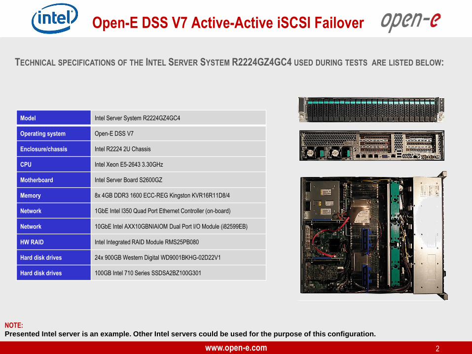
Model Intel Server System R2224GZ4GC4
Operating system Open-E DSS V7
Enclosure/chassis Intel R2224 2U Chassis
CPU Intel Xeon E5-2643 3.30GHz
Motherboard Intel Server Board S2600GZ
Memory 8x 4GB DDR3 1600 ECC-REG Kingston KVR16R11D8/4
Network 1GbE Intel I350 Quad Port Ethernet Controller (on-board)
Network 10GbE Intel AXX10GBNIAIOM Dual Port I/O Module (i82599EB)
HW RAID Intel Integrated RAID Module RMS25PB080
Hard disk drives 24x 900GB Western Digital WD9001BKHG-02D22V1
Hard disk drives 100GB Intel 710 Series SSDSA2BZ100G301
TECHNICAL SPECIFICATIONS OF THE INTEL SERVER SYSTEM R2224GZ4GC4 USED DURING TESTS ARE LISTED BELOW:
NOTE:
Presented Intel server is an example. Other Intel servers could be used for the purpose of this configuration.

www.open-e.com 3
Open-E DSS V7 Active-Active iSCSI Failover
TO SET UP ACTIVE-ACTIVE ISCSI FAILOVER ON INTEL SERVER
SYSTEMS R2224GZ4GC4, GO THROUGH THE FOLLOWING STEPS:
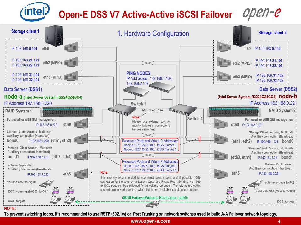
1. Hardware Configuration
2. Network Configuration
• Set server hostnames and Ethernet ports on both nodes (node-a, node-b)
3. Configure the node-b:
• Create a Volume Group, iSCSI Volume
• Configure Volume Replication mode (destination and source mode) – define remote mode of binding, create Volume Replication
task and start the replication task
4. Configure the node-a:
• Create a Volume Group, iSCSI Volume
• Configure Volume Replication mode (source and destination mode), create Volume Replication task and start the replication
task.
5. Create targets (node-a and node-b)
6. Configure Failover (node-a and node-b)
7. Start Failover Service
8. Test Failover Function
9. Run Failback Function
www.open-e.com 4
Open-E DSS V7 Active-Active iSCSI Failover
Data Server (DSS2)
node-b IP Address:192.168.0.221
Data Server (DSS1)
node-a (Intel Server System R2224GZ4GC4)
IP Address:192.168.0.220
Volume Groups (vg00) Volume Groups (vg00)
iSCSI Failover/Volume Replication (eth5) iSCSI targets
RAID System 1
PING NODES IP Addresses : 192.168.1.107,
192.168.2.107
Storage Client Access, Multipath
Auxiliary connection (Heartbeat)
bond1 IP:192.168.2.220 (eth3, eth4)
Switch 1
Switch 2
Storage Client Access, Multipath
Auxiliary connection (Heartbeat)
bond0 IP:192.168.1.220 (eth1, eth2)
Port used for WEB GUI management
IP:192.168.0.220 eth0 Port used for WEB GUI management
eth0 IP:192.168.0.221
Storage Client Access, Multipath,
Auxiliary connection (Heartbeat)
(eth3, eth4) IP:192.168.2.221 bond1
Storage Client Access, Multipath
Auxiliary connection (Heartbeat)
(eth1, eth2) IP:192.168.1.221 bond0
Storage client 1
IP:192.168.0.101 eth0
IP:192.168.21.101
IP:192.168.22.101
Volume Replication ,
Auxilliary connection (Heartbeat)
eth5 IP:192.168.5.221
Volume Replication,
Auxilliary connection (Heartbeat)
IP:192.168.5.220 eth5
iSCSI volumes (lv0000, lv0001)
iSCSI targets
iSCSI volumes (lv0000, lv0001)
Resources Pools and Virtual IP Addresses:
Node-a 192.168.31.100; iSCSI Target 0
Node-b 192.168.32.100; iSCSI Target 1
NOTE:
To prevent switching loops, it's recommended to use RSTP (802.1w) or Port Trunking on network switches used to build A-A Failover network topology.
IP:192.168.31.101
IP:192.168.32.101
eth2 (MPIO)
eth3 (MPIO)
RAID System 2
Note:
It is strongly recommended to use direct point-to-point and if possible 10Gb
connection for the volume replication. Optionally Round-Robin-Bonding with 1Gb
or 10Gb ports can be configured for the volume replication. The volume replication
connection can work over the switch, but the most reliable is a direct connection.
Storage client 2
eth0 IP:192.168.0.102
IP:192.168.21.102
IP:192.168.22.102
IP:192.168.31.102
IP:192.168.32.102
eth2 (MPIO)
eth3 (MPIO)
Note: Please use external tool to
monitor failures in connections
between switches.
RSTP/Port Trunk
Resources Pools and Virtual IP Addresses:
Node-a 192.168.21.100; iSCSI Target 0
Node-b 192.168.22.100; iSCSI Target 1
1. Hardware Configuration
(Intel Server System R2224GZ4GC4)
www.open-e.com 5
Open-E DSS V7 Active-Active iSCSI Failover
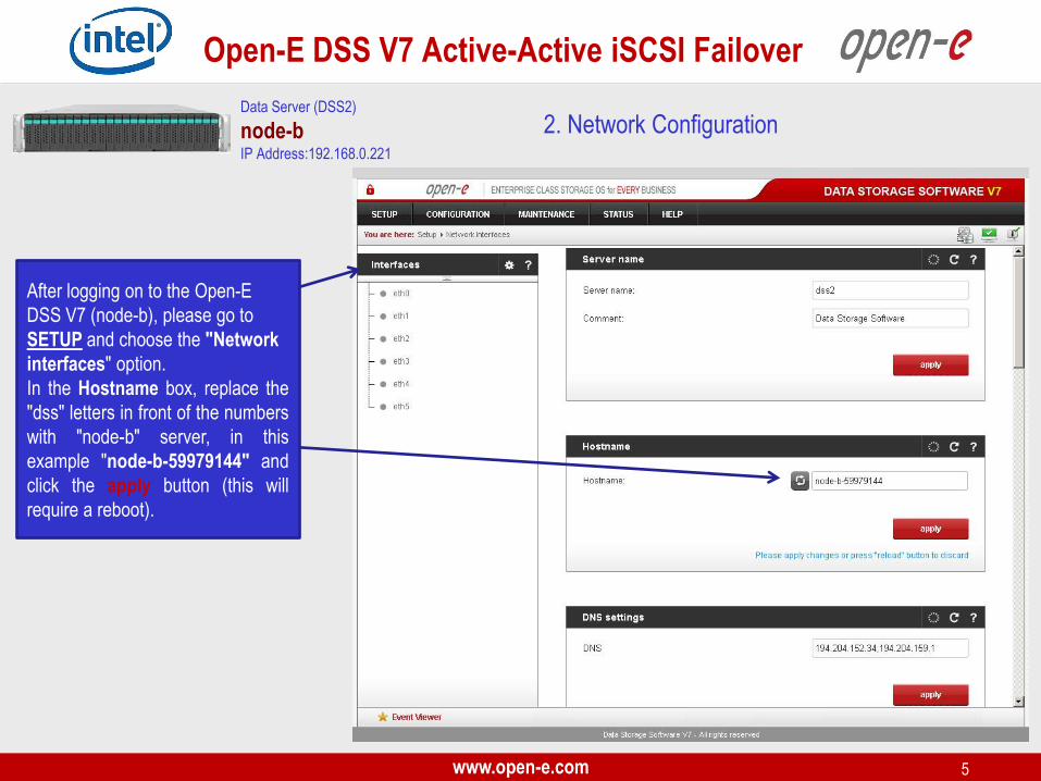
2. Network Configuration Data Server (DSS2)
node-b IP Address:192.168.0.221
After logging on to the Open-E
DSS V7 (node-b), please go to
SETUP and choose the "Network
interfaces" option.
In the Hostname box, replace the
"dss" letters in front of the numbers
with "node-b" server, in this
example "node-b-59979144" and
click the apply button (this will
require a reboot).
www.open-e.com 6
Open-E DSS V7 Active-Active iSCSI Failover
Data Server (DSS2)
node-b IP Address:192.168.0.221
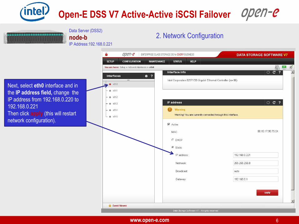
Next, select eth0 interface and in
the IP address field, change the
IP address from 192.168.0.220 to
192.168.0.221
Then click apply (this will restart
network configuration).
2. Network Configuration

www.open-e.com 7
Open-E DSS V7 Active-Active iSCSI Failover
Data Server (DSS2)
node-b IP Address:192.168.0.221
Once again, select Interfaces and
in the "Create new bond
interface" function, check two
boxes with eth1 and eth2. Next, in
the field Create select a bonding
mode. In this example select New
balance-alb.
Next, in the field Adress IP enter
192.168.1.221 and in the Netmask
field enter 255.255.255.0
Afterwards, click the create button
and confirm this action by clicking
the yes button.
2. Network Configuration

www.open-e.com 8
Open-E DSS V7 Active-Active iSCSI Failover
Data Server (DSS2)
node-b IP Address:192.168.0.221
Again, in the "Create new bond
interface" function check two
boxes with eth3 and eth4. Next, in
the field Create select a bonding
mode. In this example select New
balance-alb.
Next, in the field Adress IP enter
192.168.2.221 and in the Netmask
field enter 255.255.255.0
Afterwards, click the create button
and confirm this action by clicking
the yes button.
2. Network Configuration
www.open-e.com 9
Open-E DSS V7 Active-Active iSCSI Failover
Data Server (DSS2)
node-b IP Address:192.168.0.221
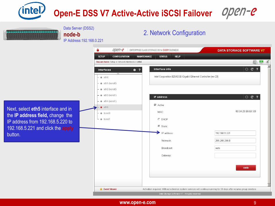
Next, select eth5 interface and in
the IP address field, change the
IP address from 192.168.5.220 to
192.168.5.221 and click the apply
button.
2. Network Configuration
www.open-e.com 10
Open-E DSS V7 Active-Active iSCSI Failover
Data Server (DSS1)
node-a IP Address:192.168.0.220
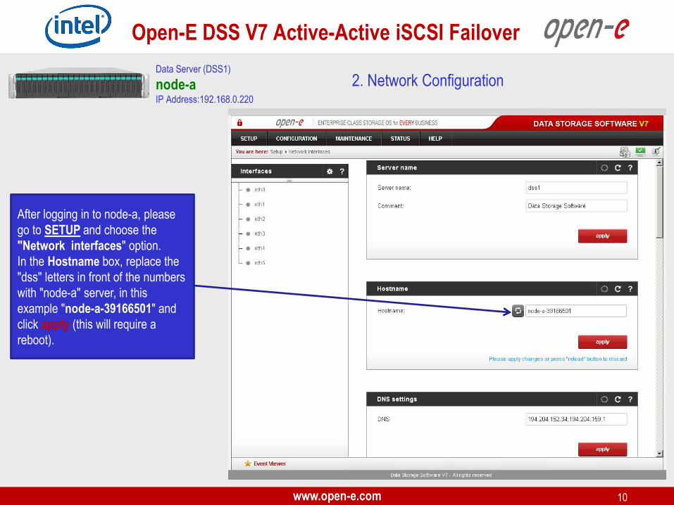
After logging in to node-a, please
go to SETUP and choose the
"Network interfaces" option.
In the Hostname box, replace the
"dss" letters in front of the numbers
with "node-a" server, in this
example "node-a-39166501" and
click apply (this will require a
reboot).
2. Network Configuration
www.open-e.com 11
Open-E DSS V7 Active-Active iSCSI Failover
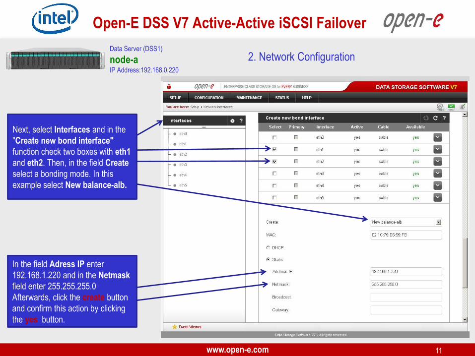
Next, select Interfaces and in the
"Create new bond interface"
function check two boxes with eth1
and eth2. Then, in the field Create
select a bonding mode. In this
example select New balance-alb.
In the field Adress IP enter
192.168.1.220 and in the Netmask
field enter 255.255.255.0
Afterwards, click the create button
and confirm this action by clicking
the yes button.
Data Server (DSS1)
node-a IP Address:192.168.0.220
2. Network Configuration
www.open-e.com 12
Open-E DSS V7 Active-Active iSCSI Failover
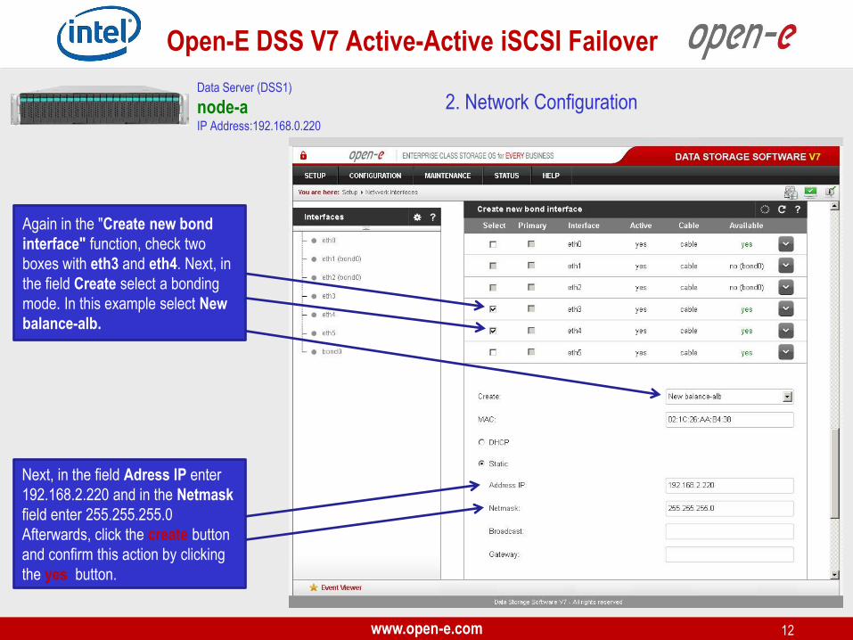
Again in the "Create new bond
interface" function, check two
boxes with eth3 and eth4. Next, in
the field Create select a bonding
mode. In this example select New
balance-alb.
Next, in the field Adress IP enter
192.168.2.220 and in the Netmask
field enter 255.255.255.0
Afterwards, click the create button
and confirm this action by clicking
the yes button.
Data Server (DSS1)
node-a IP Address:192.168.0.220
2. Network Configuration

www.open-e.com 13
Open-E DSS V7 Active-Active iSCSI Failover
3. Configure the node-b Data Server (DSS2)
node-b IP Address:192.168.0.221
In the Unit manager function
menu, add the selected physical
units (Unit MD0 or other) to create
a new volume group (in this case,
vg00) and click the apply button.
Under CONFIGURATION, select
"Volume manager", then click on
"Volume groups".
www.open-e.com 14
Open-E DSS V7 Active-Active iSCSI Failover
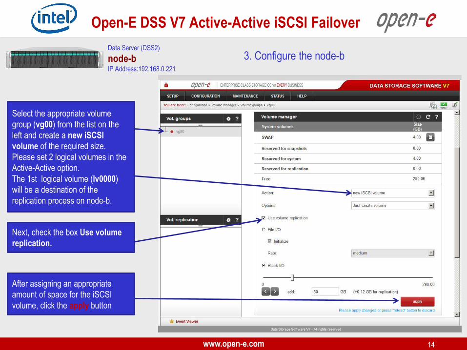
Select the appropriate volume
group (vg00) from the list on the
left and create a new iSCSI
volume of the required size.
Please set 2 logical volumes in the
Active-Active option.
The 1st logical volume (lv0000)
will be a destination of the
replication process on node-b.
After assigning an appropriate
amount of space for the iSCSI
volume, click the apply button
3. Configure the node-b
Next, check the box Use volume
replication.
Data Server (DSS2)
node-b IP Address:192.168.0.221
www.open-e.com 15
Open-E DSS V7 Active-Active iSCSI Failover
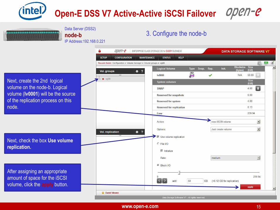
Next, create the 2nd logical
volume on the node-b. Logical
volume (lv0001) will be the source
of the replication process on this
node.
After assigning an appropriate
amount of space for the iSCSI
volume, click the apply button.
3. Configure the node-b
Next, check the box Use volume
replication.
Data Server (DSS2)
node-b IP Address:192.168.0.221
www.open-e.com 16
Open-E DSS V7 Active-Active iSCSI Failover
3. Configure the node-b
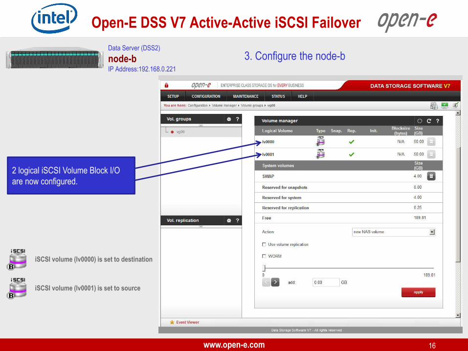
iSCSI volume (lv0000) is set to destination
Data Server (DSS2)
node-b IP Address:192.168.0.221
iSCSI volume (lv0001) is set to source
2 logical iSCSI Volume Block I/O
are now configured.
www.open-e.com 17
Open-E DSS V7 Active-Active iSCSI Failover
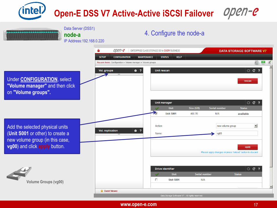
4. Configure the node-a
Volume Groups (vg00)
Add the selected physical units
(Unit S001 or other) to create a
new volume group (in this case,
vg00) and click apply button.
Data Server (DSS1)
node-a IP Address:192.168.0.220
Under CONFIGURATION, select
"Volume manager" and then click
on "Volume groups".
www.open-e.com 18
Open-E DSS V7 Active-Active iSCSI Failover
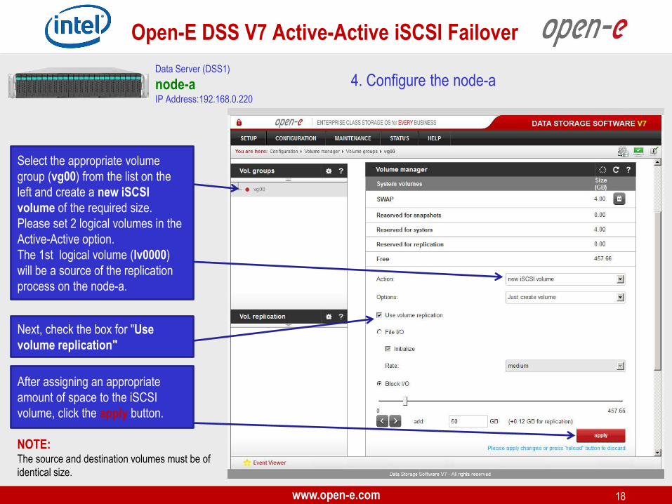
4. Configure the node-a
Select the appropriate volume
group (vg00) from the list on the
left and create a new iSCSI
volume of the required size.
Please set 2 logical volumes in the
Active-Active option.
The 1st logical volume (lv0000)
will be a source of the replication
process on the node-a.
NOTE: The source and destination volumes must be of
identical size.
Next, check the box for "Use
volume replication"
After assigning an appropriate
amount of space to the iSCSI
volume, click the apply button.
Data Server (DSS1)
node-a IP Address:192.168.0.220
www.open-e.com 19
Open-E DSS V7 Active-Active iSCSI Failover
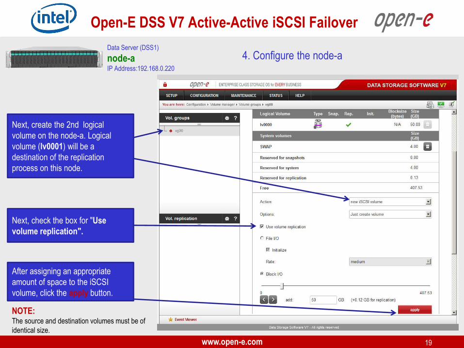
Next, create the 2nd logical
volume on the node-a. Logical
volume (lv0001) will be a
destination of the replication
process on this node.
4. Configure the node-a
Next, check the box for "Use
volume replication".
Data Server (DSS1)
node-a IP Address:192.168.0.220
NOTE: The source and destination volumes must be of
identical size.
After assigning an appropriate
amount of space to the iSCSI
volume, click the apply button.

www.open-e.com 20
Open-E DSS V7 Active-Active iSCSI Failover
4. Configure the node-a Data Server (DSS1)
node-a IP Address:192.168.0.220
iSCSI volume (lv0000) is set to source
iSCSI volume (lv0001) is set to destination
2 logical iSCSI Volume Blocks I/O
are now configured.
www.open-e.com 21
Open-E DSS V7 Active-Active iSCSI Failover
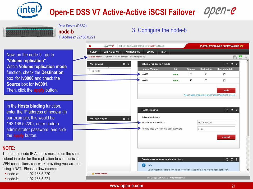
3. Configure the node-b
NOTE: The remote node IP Address must be on the same
subnet in order for the replication to communicate.
VPN connections can work providing you are not
using a NAT. Please follow example:
• node-a: 192.168.5.220
• node-b: 192.168.5.221
Data Server (DSS2)
node-b IP Address:192.168.0.221
Now, on the node-b, go to
"Volume replication".
Within Volume replication mode
function, check the Destination
box for lv0000 and check the
Source box for lv0001.
Then, click the apply button.
In the Hosts binding function,
enter the IP address of node-a (in
our example, this would be
192.168.5.220), enter node-a
administrator password and click
the apply button.
www.open-e.com 22
Open-E DSS V7 Active-Active iSCSI Failover
4. Configure the node-a Data Server (DSS1)
node-a IP Address:192.168.0.220
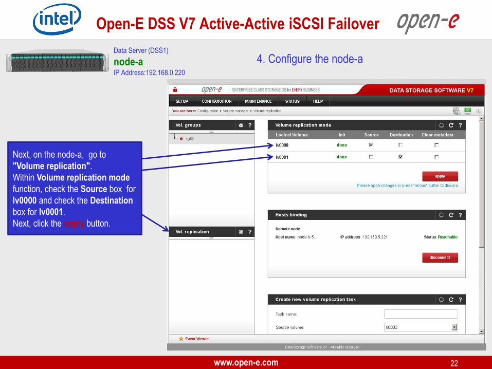
Next, on the node-a, go to
"Volume replication".
Within Volume replication mode
function, check the Source box for
lv0000 and check the Destination
box for lv0001.
Next, click the apply button.
www.open-e.com 23
Open-E DSS V7 Active-Active iSCSI Failover
4. Configure the node-a Data Server (DSS1)
node-a IP Address:192.168.0.220
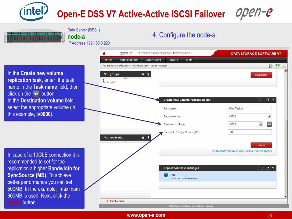
In the Create new volume
replication task, enter the task
name in the Task name field, then
click on the button.
In the Destination volume field,
select the appropriate volume (in
this example, lv0000).
In case of a 10GbE connection it is
recommended to set for the
replication a higher Bandwidth for
SyncSource (MB). To achieve
better performance you can set
500MB. In the example, maximum
600MB is used. Next, click the
create button.
www.open-e.com 24
Open-E DSS V7 Active-Active iSCSI Failover
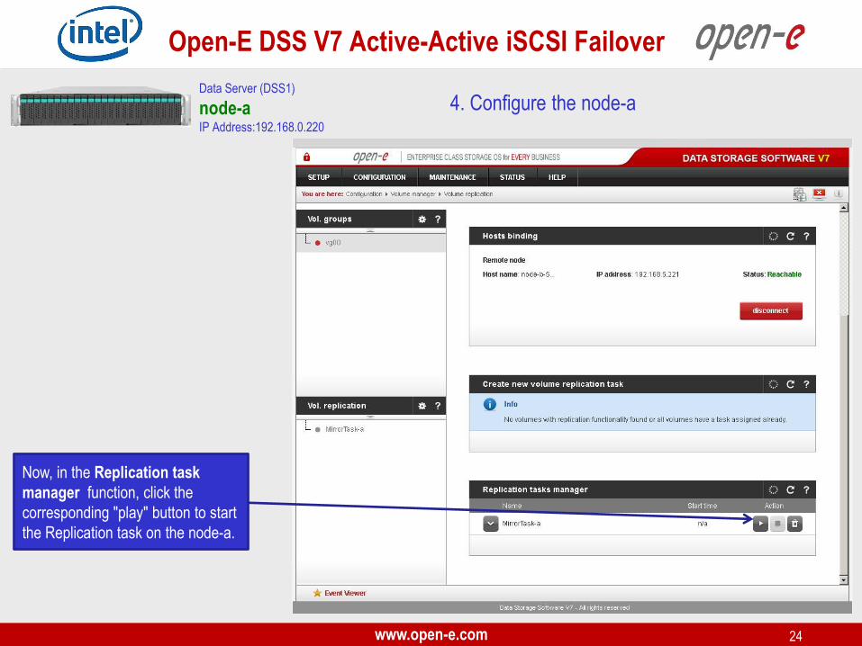
Now, in the Replication task
manager function, click the
corresponding "play" button to start
the Replication task on the node-a.
4. Configure the node-a Data Server (DSS1)
node-a IP Address:192.168.0.220
www.open-e.com 25
Open-E DSS V7 Active-Active iSCSI Failover
4. Configure the node-a
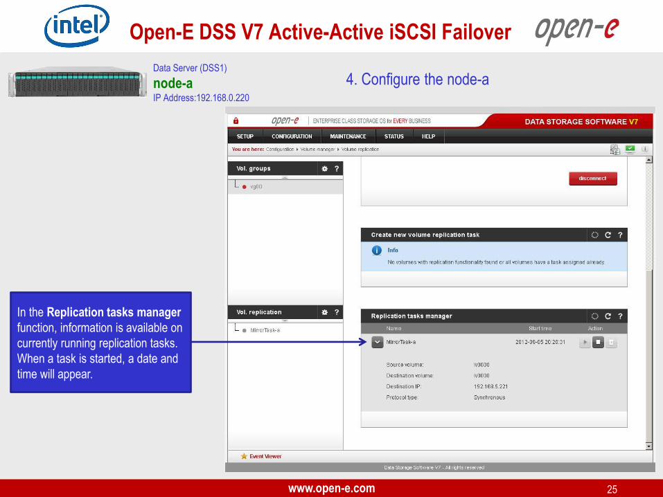
In the Replication tasks manager
function, information is available on
currently running replication tasks.
When a task is started, a date and
time will appear.
Data Server (DSS1)
node-a IP Address:192.168.0.220
www.open-e.com 26
Open-E DSS V7 Active-Active iSCSI Failover
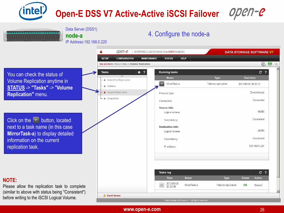
4. Configure the node-a
Click on the button, located
next to a task name (in this case
MirrorTask-a) to display detailed
information on the current
replication task.
You can check the status of
Volume Replication anytime in
STATUS -> "Tasks" -> "Volume
Replication" menu.
NOTE: Please allow the replication task to complete
(similar to above with status being "Consistent")
before writing to the iSCSI Logical Volume.
Data Server (DSS1)
node-a IP Address:192.168.0.220
www.open-e.com 27
Open-E DSS V7 Active-Active iSCSI Failover
3. Configure the node-b Data Server (DSS2)
node-b IP Address:192.168.0.221
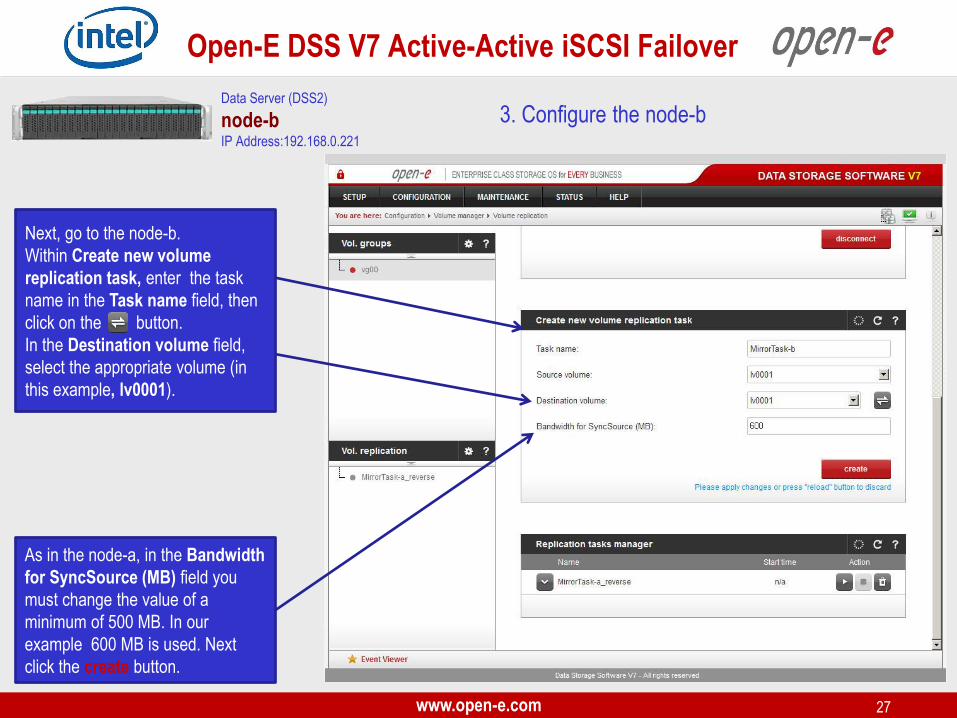
Next, go to the node-b.
Within Create new volume
replication task, enter the task
name in the Task name field, then
click on the button.
In the Destination volume field,
select the appropriate volume (in
this example, lv0001).
As in the node-a, in the Bandwidth
for SyncSource (MB) field you
must change the value of a
minimum of 500 MB. In our
example 600 MB is used. Next
click the create button.

www.open-e.com 28
Open-E DSS V7 Active-Active iSCSI Failover
3. Configure the node-b
In the Replication tasks manager
function, click the corresponding
"play" button to start the
Replication task on the node-b:
MirrorTask-b.
In this box you can find information
about currently running replication
tasks.
When a task is started a date and
time will appear.
Data Server (DSS2)
node-b IP Address:192.168.0.221

www.open-e.com 29
Open-E DSS V7 Active-Active iSCSI Failover
5. Create new target on the node-b
Choose CONFIGURATION, "iSCSI
target manager" and "Targets"
from the top menu.
NOTE: Both systems must have the same Target name.
iSCSI targets
In the Create new target function,
uncheck the box Target Default
Name.
In the Name field, enter a name for
the new target and click apply to
confirm.
Data Server (DSS2)
node-b IP Address:192.168.0.221
www.open-e.com 30
Open-E DSS V7 Active-Active iSCSI Failover
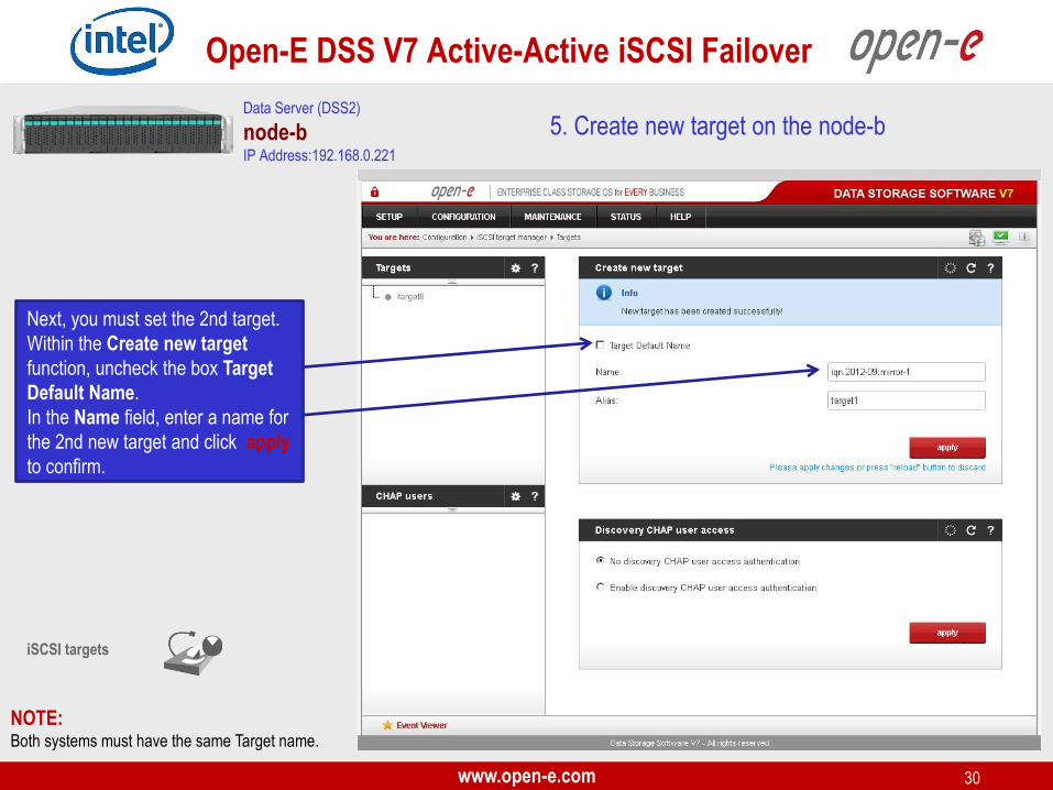
5. Create new target on the node-b
NOTE: Both systems must have the same Target name.
iSCSI targets
Next, you must set the 2nd target.
Within the Create new target
function, uncheck the box Target
Default Name.
In the Name field, enter a name for
the 2nd new target and click apply
to confirm.
Data Server (DSS2)
node-b IP Address:192.168.0.221

www.open-e.com 31
Open-E DSS V7 Active-Active iSCSI Failover
After that, select target0 within the
Targets field.
To assign appropriate volume to
the target (iqn.2012-09:mirror-0 ->
lv0000) and click the button
located under Action.
5. Create new target on the node-b
NOTE: Volumes on both sides must have the same SCSI ID and
LUN# for example: lv0000 SCSI ID on node-a = lv0000
on node-b.
WARNING: Please do not switch on the write back (WB) cache !
Data Server (DSS2)
node-b IP Address:192.168.0.221
www.open-e.com 32
Open-E DSS V7 Active-Active iSCSI Failover
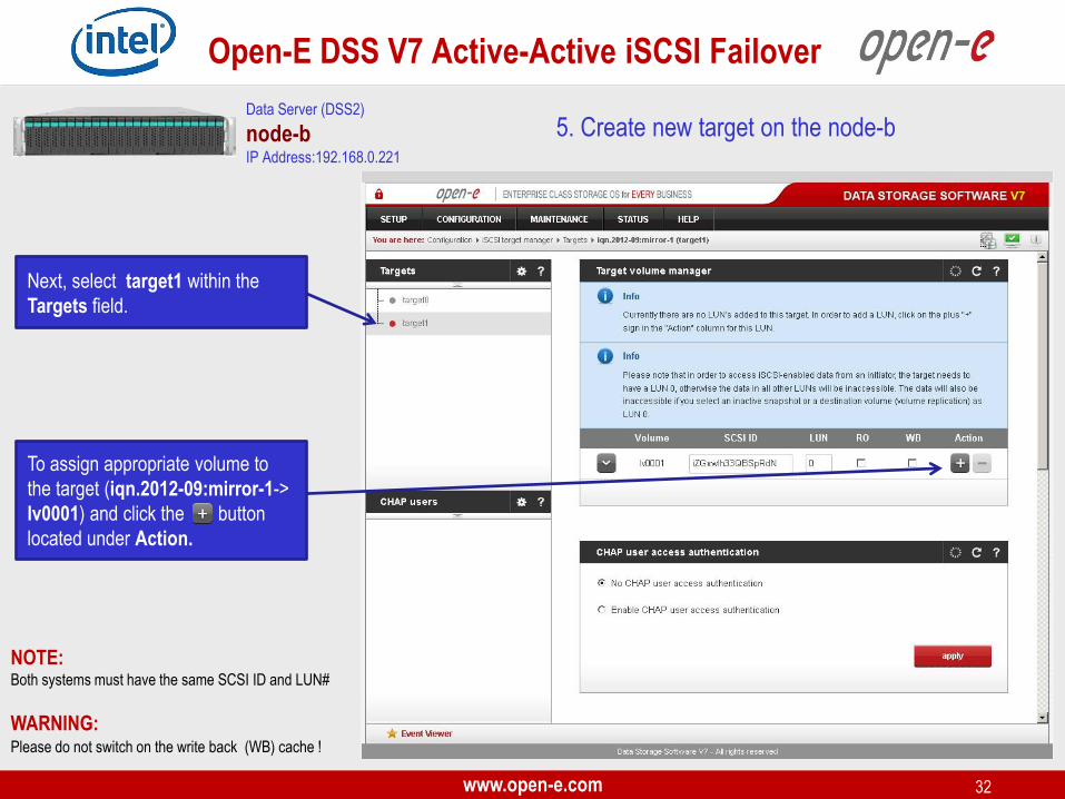
Next, select target1 within the
Targets field.
To assign appropriate volume to
the target (iqn.2012-09:mirror-1->
lv0001) and click the button
located under Action.
5. Create new target on the node-b
NOTE: Both systems must have the same SCSI ID and LUN#
WARNING: Please do not switch on the write back (WB) cache !
Data Server (DSS2)
node-b IP Address:192.168.0.221
www.open-e.com 33
Open-E DSS V7 Active-Active iSCSI Failover
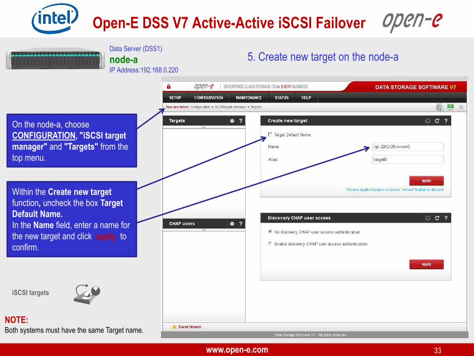
On the node-a, choose
CONFIGURATION, "iSCSI target
manager" and "Targets" from the
top menu.
NOTE: Both systems must have the same Target name.
iSCSI targets
5. Create new target on the node-a
Within the Create new target
function, uncheck the box Target
Default Name.
In the Name field, enter a name for
the new target and click apply to
confirm.
Data Server (DSS1)
node-a IP Address:192.168.0.220

www.open-e.com 34
Open-E DSS V7 Active-Active iSCSI Failover
iSCSI targets
Data Server (DSS1)
node-a IP Address:192.168.0.220
5. Create new target on the node-a
NOTE: Both systems must have the same Target name.
Next, you must set the 2nd target.
In the Create new target function,
uncheck the box Target Default
Name.
In the Name field, enter a name for
the 2nd new target and click apply
to confirm.

www.open-e.com 35
Open-E DSS V7 Active-Active iSCSI Failover
Select the target0 within the
Targets field.
To assign appropriate volume to
the target (iqn.2012-09:mirror-0 ->
lv0000) and click the button
located under Action.
5. Create new target on the node-a
WARNING: Please do not switch on the write back cache (WB) !
Data Server (DSS1)
node-a IP Address:192.168.0.220
NOTE: Before clicking the button again, please
copy & paste the SCSI ID and LUN#
from the node-b.
www.open-e.com 36
Open-E DSS V7 Active-Active iSCSI Failover
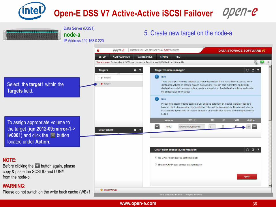
Select the target1 within the
Targets field.
To assign appropriate volume to
the target (iqn.2012-09:mirror-1->
lv0001) and click the button
located under Action.
5. Create new target on the node-a
WARNING: Please do not switch on the write back cache (WB) !
Data Server (DSS1)
node-a IP Address:192.168.0.220
NOTE: Before clicking the button again, please
copy & paste the SCSI ID and LUN#
from the node-b.

www.open-e.com 37
Open-E DSS V7 Active-Active iSCSI Failover
6. Configure Failover
On the node-a, go to SETUP and
select "Failover".
In the Auxiliary paths function,
select the 1st New auxiliary path
on the local and remote node and
click the add new auxiliary path
button.
Data Server (DSS1)
node-a IP Address:192.168.0.220

www.open-e.com 38
Open-E DSS V7 Active-Active iSCSI Failover
6. Configure Failover
In the Auxiliary paths function,
select the 2nd New auxiliary path
on the local and remote node and
click the add new auxiliary path
button.
Data Server (DSS1)
node-a IP Address:192.168.0.220
www.open-e.com 39
Open-E DSS V7 Active-Active iSCSI Failover
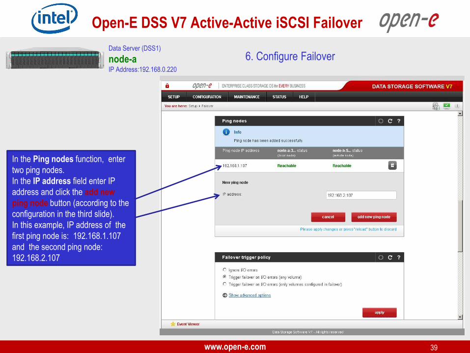
6. Configure Failover Data Server (DSS1)
node-a IP Address:192.168.0.220
In the Ping nodes function, enter
two ping nodes.
In the IP address field enter IP
address and click the add new
ping node button (according to the
configuration in the third slide).
In this example, IP address of the
first ping node is: 192.168.1.107
and the second ping node:
192.168.2.107
www.open-e.com 40
Open-E DSS V7 Active-Active iSCSI Failover
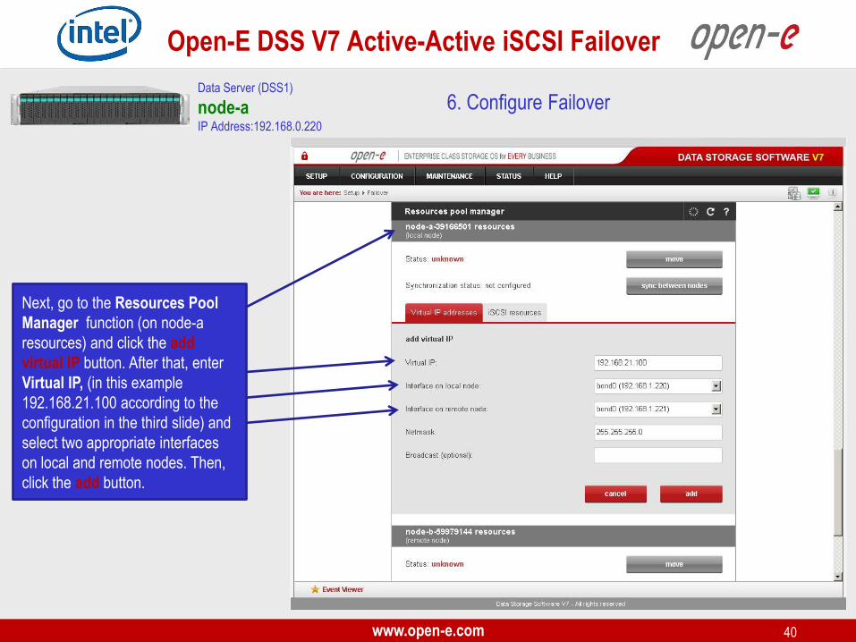
6. Configure Failover Data Server (DSS1)
node-a IP Address:192.168.0.220
Next, go to the Resources Pool
Manager function (on node-a
resources) and click the add
virtual IP button. After that, enter
Virtual IP, (in this example
192.168.21.100 according to the
configuration in the third slide) and
select two appropriate interfaces
on local and remote nodes. Then,
click the add button.
www.open-e.com 41
Open-E DSS V7 Active-Active iSCSI Failover
6. Configure Failover Data Server (DSS1)
node-a IP Address:192.168.0.220
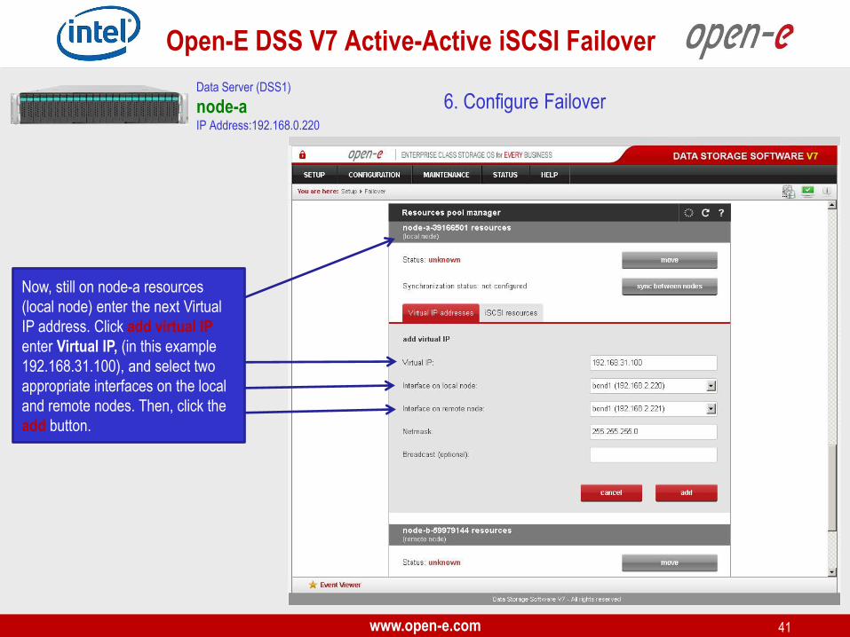
Now, still on node-a resources
(local node) enter the next Virtual
IP address. Click add virtual IP
enter Virtual IP, (in this example
192.168.31.100), and select two
appropriate interfaces on the local
and remote nodes. Then, click the
add button.
www.open-e.com 42
Open-E DSS V7 Active-Active iSCSI Failover
6. Configure Failover Data Server (DSS1)
node-a IP Address:192.168.0.220
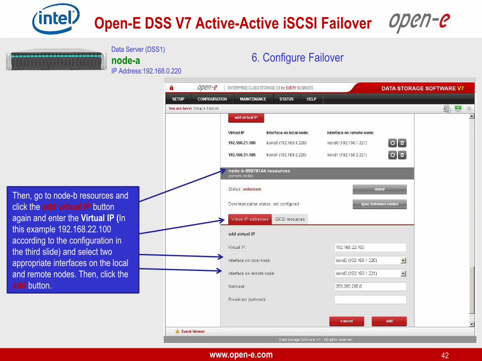
Then, go to node-b resources and
click the add virtual IP button
again and enter the Virtual IP (In
this example 192.168.22.100
according to the configuration in
the third slide) and select two
appropriate interfaces on the local
and remote nodes. Then, click the
add button.

www.open-e.com 43
Open-E DSS V7 Active-Active iSCSI Failover
6. Configure Failover Data Server (DSS1)
node-a IP Address:192.168.0.220
Now, still on node-b resources,
click the add virtual IP button and
enter the next Virtual IP, (in this
example 192.168.32.100,
according to the configuration in
the third slide) and select two
appropriate interfaces on the local
and remote nodes. Then, click the
add button.

www.open-e.com 44
Open-E DSS V7 Active-Active iSCSI Failover
6. Configure Failover Data Server (DSS1)
node-a IP Address:192.168.0.220
Now you have 4 Virtual IP
addresses configured on two
interfaces.
www.open-e.com 45
Open-E DSS V7 Active-Active iSCSI Failover
6. Configure Failover Data Server (DSS1)
node-a IP Address:192.168.0.220
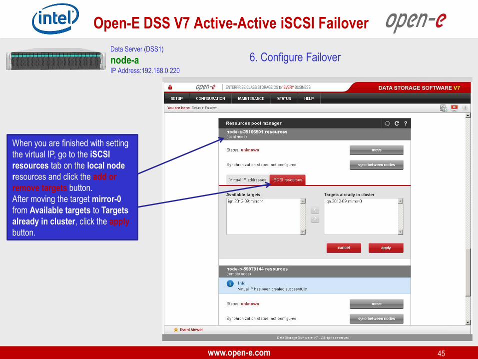
When you are finished with setting
the virtual IP, go to the iSCSI
resources tab on the local node
resources and click the add or
remove targets button.
After moving the target mirror-0
from Available targets to Targets
already in cluster, click the apply
button.
www.open-e.com 46
Open-E DSS V7 Active-Active iSCSI Failover
6. Configure Failover Data Server (DSS1)
node-a IP Address:192.168.0.220
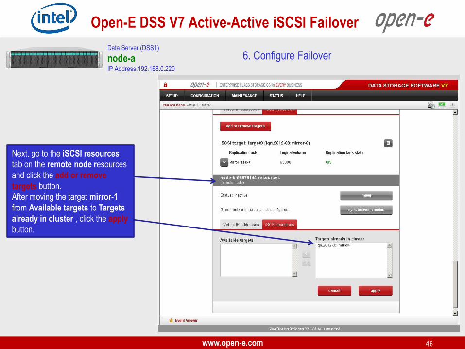
Next, go to the iSCSI resources
tab on the remote node resources
and click the add or remove
targets button.
After moving the target mirror-1
from Available targets to Targets
already in cluster , click the apply
button.

www.open-e.com 47
Open-E DSS V7 Active-Active iSCSI Failover
6. Configure Failover Data Server (DSS1)
node-a IP Address:192.168.0.220
After that, scroll to the top of the
Failover manager function.
At this point, both nodes are ready
to start the Failover.
In order to run the Failover service,
click the start button and confirm
this action by clicking the start
button again.
NOTE: If the start button is grayed out, the setup has not been
completed.
www.open-e.com 48
Open-E DSS V7 Active-Active iSCSI Failover
Data Server (DSS1)
node-a IP Address:192.168.0.220
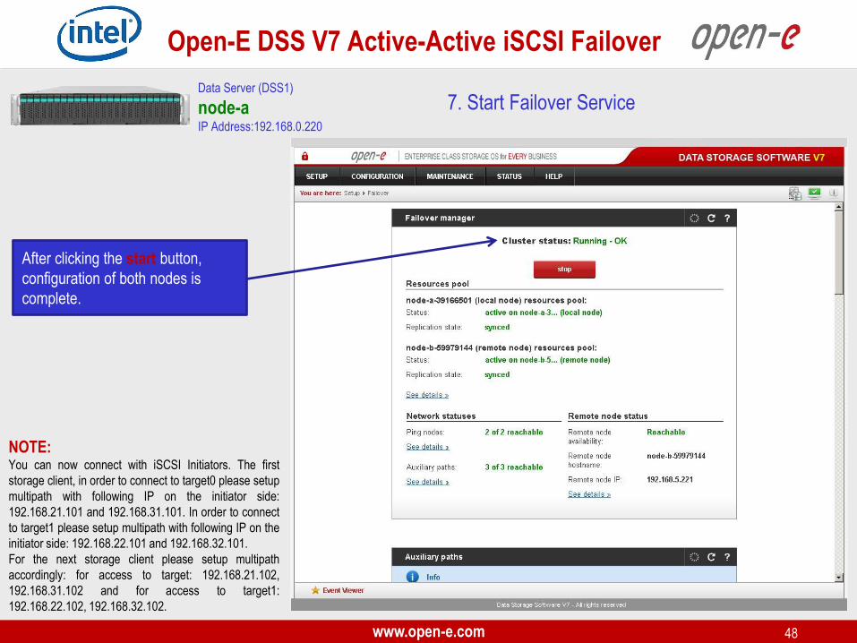
After clicking the start button,
configuration of both nodes is
complete.
NOTE: You can now connect with iSCSI Initiators. The first
storage client, in order to connect to target0 please setup
multipath with following IP on the initiator side:
192.168.21.101 and 192.168.31.101. In order to connect
to target1 please setup multipath with following IP on the
initiator side: 192.168.22.101 and 192.168.32.101.
For the next storage client please setup multipath
accordingly: for access to target: 192.168.21.102,
192.168.31.102 and for access to target1:
192.168.22.102, 192.168.32.102.
7. Start Failover Service
www.open-e.com 49
Open-E DSS V7 Active-Active iSCSI Failover
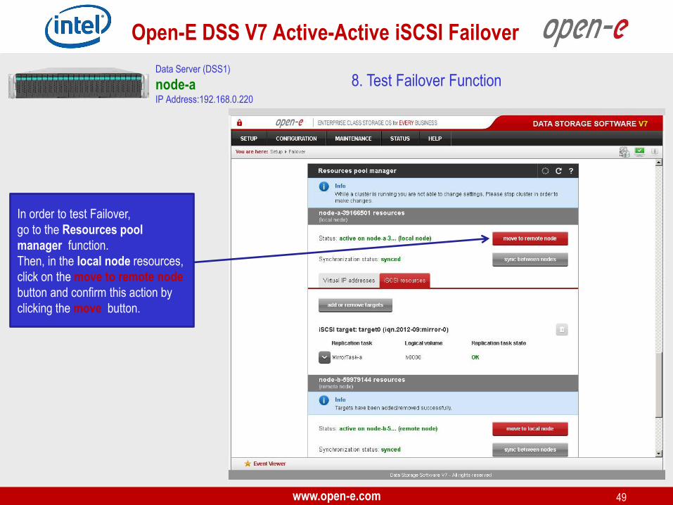
8. Test Failover Function
In order to test Failover,
go to the Resources pool
manager function.
Then, in the local node resources,
click on the move to remote node
button and confirm this action by
clicking the move button.
Data Server (DSS1)
node-a IP Address:192.168.0.220
www.open-e.com 50
Open-E DSS V7 Active-Active iSCSI Failover
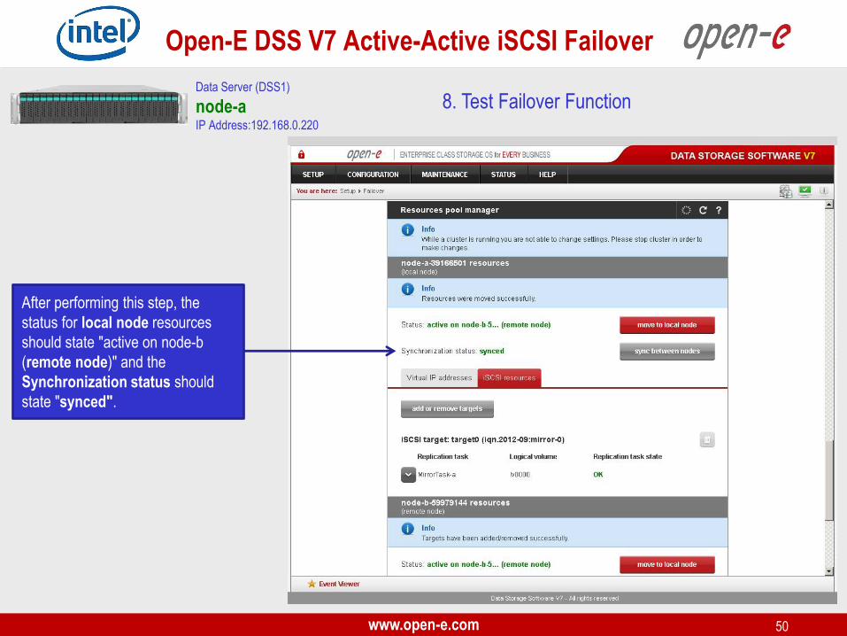
After performing this step, the
status for local node resources
should state "active on node-b
(remote node)" and the
Synchronization status should
state "synced".
8. Test Failover Function Data Server (DSS1)
node-a IP Address:192.168.0.220
www.open-e.com 51
Open-E DSS V7 Active-Active iSCSI Failover
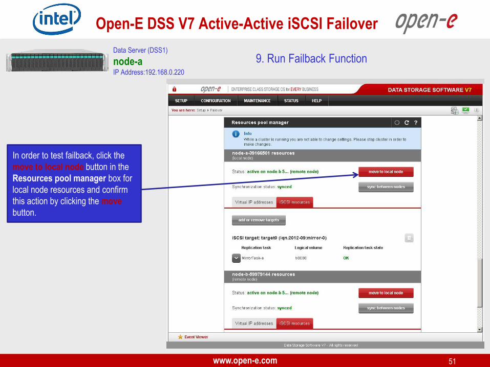
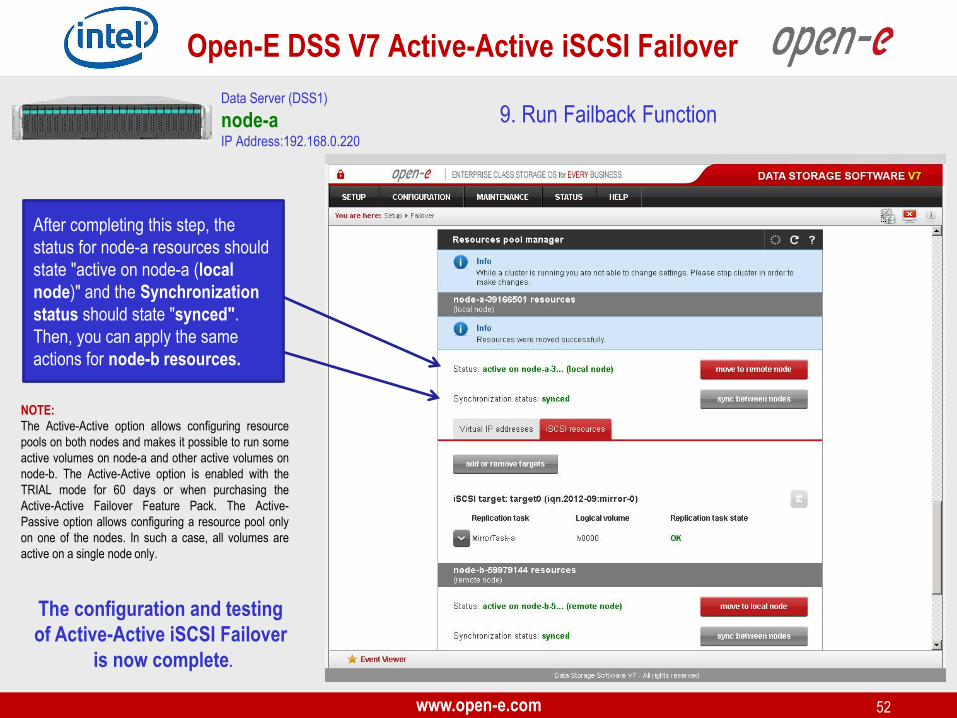
9. Run Failback Function
In order to test failback, click the
move to local node button in the
Resources pool manager box for
local node resources and confirm
this action by clicking the move
button.
Data Server (DSS1)
node-a IP Address:192.168.0.220
www.open-e.com 52
Open-E DSS V7 Active-Active iSCSI Failover
9. Run Failback Function Data Server (DSS1)
node-a IP Address:192.168.0.220
After completing this step, the
status for node-a resources should
state "active on node-a (local
node)" and the Synchronization
status should state "synced".
Then, you can apply the same
actions for node-b resources.
The configuration and testing
of Active-Active iSCSI Failover
is now complete.
NOTE:
The Active-Active option allows configuring resource
pools on both nodes and makes it possible to run some
active volumes on node-a and other active volumes on
node-b. The Active-Active option is enabled with the
TRIAL mode for 60 days or when purchasing the
Active-Active Failover Feature Pack. The Active-
Passive option allows configuring a resource pool only
on one of the nodes. In such a case, all volumes are
active on a single node only.
www.open-e.com 53
Open-E DSS V7 Active-Active iSCSI Failover
Follow Open-E:
Thank you!