OPC Risk Red Rev C v5 - Canada.ca€¦ · Seabridge Gold February 20, 2012 KSM Geohazards: OPC...
33
TM APPENDIX 9-C KSM GEOHAZARDS: OPC PRE-FEASIBILITY GEOHAZARDS RISK REDUCTION: REV C
Transcript of OPC Risk Red Rev C v5 - Canada.ca€¦ · Seabridge Gold February 20, 2012 KSM Geohazards: OPC...

TM
APPENDIX 9-C KSM GEOHAZARDS: OPC PRE-FEASIBILITY
GEOHAZARDS RISK REDUCTION: REV C

A p p e n d i x F 7
M i t c h e l l O P C G e o h a z a r d s R i s k R e d u c t i o n

Suite 500 - 1045 Howe Street, Vancouver, British Columbia, Canada. V6Z 2A9
Telephone (604) 684-5900 Fax (604) 684-5909
C:\Documents and Settings\astrouth\Desktop\KSM\41B. Ore Preparation Complex Geohazard Mitigation PFS Design\3. Reporting\OPC Risk Red Rev C_v5.docx
BGC ENGINEERING INC.
BGC Project Memorandum To: SEABRIDGE GOLD INC. Attention: Brent Murphy, Seabridge
Jim Smolik, Seabridge cc: Kris Holm
From: Alex Strouth, Brian Gould, Mark
Pritchard Date: February 20, 2012
Subject: KSM Geohazards: OPC Pre-feasibility Geohazards Risk Reduction – Rev. C
Project no: 0638-013-41
1.0 INTRODUCTION
1.1. General BGC Engineering Inc. (BGC) provided Seabridge Gold Inc. (Seabridge) with an April 21, 2011 memorandum (BGC, 2011b) describing pre-feasibility level design of landslide and snow avalanche geohazard risk reduction measures for the Ore Preparation Complex (OPC), located in Mitchell Valley. That OPC arrangement included grinding and HPGR buildings, electric rooms, an electric substation, a primary crusher, stock piles and fuel facilities. That same arrangement was assessed in BGC’s geohazard risk report (Rev B) dated August 24, 2011 (BGC, 2011c), which estimates the geohazard risk to proposed facilities, ranging from Very Low to Very High.
Since those reports, the OPC layout has changed to include only the primary crusher, coarse ore stockpile, Mitchell-Teigen tunnel (MTT) portals and a smaller electrical substation (Drawing_1). Also the platform containing the MTT portals was moved to a lower elevation (El. 820 m).
These facilities are located on two platforms near the base of the Mill Site and Haul Road Gullies1. Crushed ore will be conveyed from the coarse ore stockpile through the Mitchell-Teigen Tunnel (MTT) for further processing near the north tunnel entrance. In addition to the OPC layout changes, the North Haul Road across the slope above the OPC has been eliminated. The North Haul Road was relied on in the previous iteration to provide partial protection against snow avalanche and rock fall hazard to the OPC.
1 these names are informal and are used by BGC to avoid naming confusion, see Drawing 1.

Seabridge Gold February 20, 2012 KSM Geohazards: OPC Pre-feasibility Geohazards Risk Reduction – Rev. C Project No. 0638-013
OPC Risk Red Rev C_v5.docx Page 2
BGC ENGINEERING INC.
The current arrangement of the platforms, shown on Drawing 1, is based on a drawing provided by Moose Mountain Technical Services (MMTS) on February 3, 2012. Layout of the facilities, on top of the platforms, is based on Drawing 10-10-1715 (Rev N), received from MMTS on December 7, 2011.
The OPC is located in a high frequency snow avalanche zone in the Mitchell Valley. Relocation of the OPC outside of the avalanche hazard zone is the preferred option to reduce geohazard risk. However, BGC understands that relocation of the OPC is not considered viable. As such, geohazard protection measures are required.
This memorandum updates the geohazard protection measures proposed around the OPC to address the current facility arrangement (Rev N), at a pre-feasibility update level of design. This memorandum supersedes and replaces BGC (2011b). Geohazard protection measures are proposed that are expected to reduce High and Very High risk scenarios to a target residual risk not exceeding Moderate, as specified by KSM. The design basis for debris flow and rockfall risk reduction was prepared by BGC. The design basis for avalanche risk reduction and for recommended snow catchment area and pre-feasibility level structural design loads was prepared by Alpine Solutions.
1.2. Work Scope This memorandum provides the following information:
• A summary of the High and Very High geohazard risk scenarios at the OPC.
• A description of two potential geohazard risk management plans.
• The design basis for geohazards affecting the OPC.
• Drawings illustrating the arrangement of physical risk reduction measures.
• Geometric information for structures for preparation of cost estimates.
For convenience of discussion in this memorandum, the OPC is separated into two sections, or platforms (Drawing 1), including the:
• Central Platform, including the coarse ore stockpile, main electrical substation and MTT transportation and conveyor tunnel portals; and
• Eastern Platform, including the primary crusher facility; This memorandum only considers the facilities listed above. The location of the fuel storage facility and access roads between platforms have not been defined by the time of writing, and therefore have not been included in this scope of work.

Seabridge Gold February 20, 2012 KSM Geohazards: OPC Pre-feasibility Geohazards Risk Reduction – Rev. C Project No. 0638-013
OPC Risk Red Rev C_v5.docx Page 3
BGC ENGINEERING INC.
2.0 GEOHAZARD RISK SUMMARY
As noted in BGC (2011c), the Ore Preparation Complex is subject to:
• dry and wet snow avalanches;
• debris flows; and
• rock falls and other landslides.
Dry snow avalanches may affect the entire footprint. Wet snow avalanches and debris flows are confined to the Haul Road Gully, and Mill Site Gully (Drawing 1). Rock fall and other types of landslides may occur from natural slopes upslope of the footprint. Even though BGC’s work (2011c) related to naturally occurring geohazards, rock fall can occur from artificially created slopes as well. Geohazard risk levels estimated in BGC (2011c) are listed in Table 2-1. Changes to the layout since BGC (2011c) reduce the number of facilities exposed to these geohazards, but do not alter the geohazard risk scenarios or the risk rating provided in Table 2-1 for the remaining infrastructure.
Table 2-1 Geohazard risk scenarios for the Ore Preparation Complex (BGC, 2011c) Scenario
No. Process/Scenario Direct Consequence Risk Target Risk
1 Snow avalanche impact (Size 2-4) Damage/destruction of facilities Very High Moderate
2 Snow avalanche impact (Size 2-4) Single and multiple fatalities Very High Moderate
3 Debris flow impact (Size 3) Damage of facilities/single fatality High Moderate
4 Debris flow impact (Size 4)
Damage of facilities//multiple fatalities High Moderate
5 Rock fall impact Single fatality High Moderate Note: Does not include construction induced geohazards such as rock fall from cut slopes
The predominant (i.e. highest hazard intensity) geohazard affecting the Ore Preparation Complex is snow avalanches, at (unmitigated) frequencies of several per year at low magnitude (Size 2), once per year for medium (Size 3) avalanches, and perhaps once in 5-10 years for large avalanches (Size 4). If not mitigated, avalanches are likely to severely damage facilities and cause loss of life if personnel are present at the facilities. For reference, characteristics of these avalanche magnitudes are summarized in Table 2-2. Table 2-3 describes the size classification for debris flows.

Seabridge Gold February 20, 2012 KSM Geohazards: OPC Pre-feasibility Geohazards Risk Reduction – Rev. C Project No. 0638-013
OPC Risk Red Rev C_v5.docx Page 4
BGC ENGINEERING INC.
Table 2-2 Canadian Classification System for Avalanche Size (CAA, 2002)
Size Destructive Potential Typical Mass
(tonnes)
Typical Path Length
(m)
Typical Impact Pressure
(kPa)
1 Relatively harmless to people <10 10 1
2 Could bury, injure or kill a person. 100 100 10
3 Could bury a car, destroy a small building, or break a few trees 1,000 1,000 100
4 Could destroy a large truck, several buildings, or a forest with an area up to 4 hectares
10,000 2,000 500
5 Largest snow avalanches known. Could destroy a village or a 40 ha forest
100,000 3,000 1,000
Table 2-3 Definition of Size Classification for Debris Flows (after Jakob, 2005)
Size Class Volume Range (m3)
Discharge Range (m3/s) (Coarse-Grained Debris Flows)
0 < 101 n/a
1 < 102 < 5
2 102 - 103 5 – 30
3 103 – 104 30 – 200
4 104 – 105 200 – 1,500
5 105 – 106 1,500 – 12,000
6 106 – 107 n/a

Seabridge Gold February 20, 2012 KSM Geohazards: OPC Pre-feasibility Geohazards Risk Reduction – Rev. C Project No. 0638-013
OPC Risk Red Rev C_v5.docx Page 5
BGC ENGINEERING INC.
3.0 GEOHAZARD RISK REDUCTION CONCEPTUAL DESIGN
3.1. Overall Risk Reduction Strategy The OPC is a critical mine facility with processing equipment intended to operate 24 hours per day, 365 days per year. Furthermore, the facilities are frequented by people who will need to be protected from geohazards, particularly during construction but also during operations.
In general, geohazard risk can be reduced by reducing the:
• probability of events occurring;
• magnitude (volume, peak discharge) and thus intensity (runout distance, velocity, impact forces) of events;
• spatial probability of impact (likelihood that the geohazard will reach or impact the element at risk);
• temporal probability of impact (likelihood of workers being present in the zone subject to the hazard); and
• vulnerability (the degree of loss to a given element at risk within the area affected by the snow avalanche or landslide hazard).
As requested by the project team, two different general options are proposed to reduce personnel safety risk:
1. Protection of platforms and facilities with high barrier walls; or
2. Evacuation of platforms and facilities during periods of high avalanche hazard.
Both options are capable of reducing personnel safety risk to an acceptable level (moderate). The first option also reduces the risk of economic loss caused by facility shutdown or damage, but is a larger initial investment. The second option allows facilities to be impacted by avalanches, and the potential for economic loss during operation is higher. The following sections discuss these two options.
Avalanche risk is discussed first because snow avalanches are the dominant geohazard. Many risk mitigation strategies for design avalanches are also effective against the other hazards.
3.2. Avalanche Risk Mitigation and Event Assumptions
3.2.1. General
The overall concept of avalanche risk reduction is to avoid reliance on one system and create a multiple defense chain. This approach creates redundancy that addresses the uncertainty in estimation of the design event volumes and discharge, and allows for potential temporary compromise of one of the defense systems.
Potential hazard and risk reduction structures include:

Seabridge Gold February 20, 2012 KSM Geohazards: OPC Pre-feasibility Geohazards Risk Reduction – Rev. C Project No. 0638-013
OPC Risk Red Rev C_v5.docx Page 6
BGC ENGINEERING INC.
• snow supporting structures (snow fences or nets);
• fixed remote control explosive device installations for avalanche triggering;
• arrangement of the cut and fill platforms for the facilities to provide avalanche flow channels and storage at the outlets of the main gullies;
• portal extension protection for tunnel portals;
• unoccupied catchment space on the north side (cut slope side) of the platforms;
• facility design to resist avalanche impact damage; and/or
• free-standing walls on the OPC platforms to protect facilities and enclose avalanche catchment areas.
3.2.2. Dry Snow Avalanches
The magnitude and frequency of the design dry snow avalanche event reaching the OPC platforms depends on the avalanche risk reduction plan for the slopes above the OPC. For the purposes of this memorandum, the following up-slope avalanche management is assumed:
• Avalanche explosive control throughout the winter and spring season by incorporating numerous fixed remote-control exploders in avalanche starting zones above the OPC. These would be located where the resulting run out enters one of the principal gullies. These exploders would be initiated by experienced avalanche technicians numerous times during storm cycles to increase the frequency of avalanches, while concurrently reducing the chance of a large-magnitude dry snow avalanche.
• Snow supporting structures (snow nets or fences) constructed on the slope within initiation zones of avalanches that would potentially run-out onto an OPC platform. This will primarily be on the slopes between Mill Site Gully and Haul Road Gully above the Central Platform. These structures anchor snow to the slopes, thereby limiting avalanche initiation.
Conceptual design and quantities for fixed remote control explosive devices and up-slope snow support structure installations have been provided in Alpine Solutions (2011) as part of an overall assessment of these measures for the entire project area.
The proposed up-slope snow supporting structures (snow nets or fencing) and avalanche explosive control plan will not prevent snow avalanches from reaching the OPC. Dry snow avalanches are expected to runout onto the OPC platforms several times per year. The purpose of the up-slope avalanche management is to reduce the magnitude of snow avalanches that reach the OPC. This reduction of avalanche magnitude (volume and intensity) reduces the technical requirements for additional protection at the OPC platform elevation to a feasible level. Two general options are proposed to reduce risk associated with dry snow avalanches that reach the OPC platforms:

Seabridge Gold February 20, 2012 KSM Geohazards: OPC Pre-feasibility Geohazards Risk Reduction – Rev. C Project No. 0638-013
OPC Risk Red Rev C_v5.docx Page 7
BGC ENGINEERING INC.
Option1: Avalanche defense walls and catchment zones constructed as a line of avalanche defense on the upstream side (typically north side) of the OPC platforms. For the Central Platform, these measures would be designed to protect the tunnel portals and stockpile area from avalanches that initiate from the slopes that contain the snow support structures, and from the steep slopes below the support structures. For this platform, we understand that the electrical substation will be hardened to resist avalanches and rock fall, and will be accessed from inside the conveyor tunnel. For the Eastern Platform, these measures would be designed to protect the platform and primary crusher from avalanches that initiate on the slopes above the Mill Site gully that might run across the Mill Site gully. This might occur later in the avalanche season as the gully becomes full from accumulated released avalanches over the winter. The avalanche defense walls are an investment. They may be a costly capital expenditure, but in the long term avalanche defense walls will reduce:
o repair costs associated with infrastructure damage caused by avalanche and rock fall impacts;
o the occurrence and duration of facility evacuations and shutdowns; o risk of injury or death to workers on the platforms; and o uncertainty associated with estimation of rockfall and avalanche risk to
personnel and infrastructure. Option 2: Routine evacuation and access restrictions to platforms during periods of high avalanche hazard. Avalanche defense walls would be minimized or removed from the design. Safety risk to personnel would be managed by evacuating personnel from the OPC platforms, possibly several times per year for several days, when the on-site snow avalanche technician team identify high avalanche hazard. Shut down of the OPC facilities may be required during the personnel evacuations, unless the facilities can be controlled remotely. Shut down of the facilities may continue after avalanches occur if infrastructure is damaged, and while snow is removed to restore access to the facilities. The economic losses during operation associated with this option are likely higher than option_1, but are also highly uncertain. Economic risks can be reduced by designing facilities to resist avalanche impact forces, and designing the processing system to allow for routine shut down of the OPC facilities. For example, it may be possible to offset the impact of OPC shutdowns by providing for additional storage of crushed ore on the north side of the Mitchell-Teigen Tunnel. The economic risk associated with Option 2 has not been quantified because it depends heavily on facility design details which have not been provided at this stage. ‘Major’, ‘Severe’, or ‘Catastrophic’ economic consequences (resulting in ‘High’ or ‘Very High’ risk) could be caused by an avalanche that severely damages or destroys the primary crusher, or other critical structure. If walls are removed from the design, the designers must consider that the facilities themselves will be potentially impacted

Seabridge Gold February 20, 2012 KSM Geohazards: OPC Pre-feasibility Geohazards Risk Reduction – Rev. C Project No. 0638-013
OPC Risk Red Rev C_v5.docx Page 8
BGC ENGINEERING INC.
by avalanches several times in the same season, and the facilities could be impacted by an exceptional event (very rare) that exceeds the provided design impact forces.
3.2.3. Dry Snow Avalanche Design Event
The up-slope avalanche management program described in the previous section is expected to limit the size of dry snow avalanches that reach the OPC to Size 2 (see Table 2-2). However, we conservatively use Size 3 at this stage of study as a design basis for risk reduction structures for dry snow avalanche events. Design recommendations for avalanche defense walls and catchment zones consider that there may be periods of several days during a storm when multiple avalanches are triggered or occur and run into constructed catchment areas at the OPC. During such an event, clearing out the avalanche catchment may not be possible for safety reasons. As such, sizing of catchment area and barrier heights considers storage of multiple design events. If defense walls and catchment zones are not included in the design, then portions of the platform, or the entire platform, may be inaccessible to personnel during such a storm event.
3.2.4. Wet Snow Avalanches
The dry snow avalanche management plan will increase deposition of avalanche deposits in the principal gullies above the OPC, which creates a risk of larger wet snow avalanches in the principal gullies (Mill Site Gully, Haul Road Gully, Mid Slope Gully).
Wet snow avalanches could occur in one of the three principal gullies when a large snow mass that has accumulated from dry avalanche releases over the winter becomes isothermal (0°C throughout the snow profile) and loses cohesive properties.
The risk reduction plan for wet snow avalanche hazard is to funnel the wet-snow avalanches into designated channels and catchment areas between the OPC platforms. The plan allows for snow and/or debris accumulation and subsequent snow removal to preserve storage area for subsequent avalanches.
3.2.5. Wet Snow Avalanche Design Event
Wet snow avalanches in the major gullies are expected to occur once every three to five years, and they are more likely under a combination of conditions including:
• an extreme snowpack year with extensive avalanche snow deposits in the gullies;
• an isothermal snowpack with high pore-water pressures;
• weak structure at the base of the gully snowpack and avalanche debris;
• impervious or low permeability bedrock below the snowpack that causes a wet gliding layer to form; and
• a heavy rain event that promotes high rates of convective heat transfer into the snowpack.

Seabridge Gold February 20, 2012 KSM Geohazards: OPC Pre-feasibility Geohazards Risk Reduction – Rev. C Project No. 0638-013
OPC Risk Red Rev C_v5.docx Page 9
BGC ENGINEERING INC.
The quasi-simultaneous occurrence of these conditions, in varying degrees, could lead to an abrupt loss of cohesion and thus strength of the avalanche debris in gullies, resulting in a large wet snow avalanche or slush flow.
Characteristics of wet snow or slush avalanches for this site include:
• flow is readily deflected and follows terrain features such as existing gullies and constructed diversions;
• flow could entrain underlying loose debris;
• maximum possible velocity of flow would be approximately 25 m/s;
• flow can run up and super-elevate against obstacles in the channel and runout zone;
• flow is very dense snow (500 kg/m3); and
• flow may slow down and stop on slope inclines of 15° or less.
Design snow volumes for wet snow avalanches that originate in each of these three gullies are estimated by considering an extreme winter’s (approximately 100-year return period) snow accumulation, and calculating the entire volume in the start zone, track, and runout zone. Then, using established reduction factors (to estimate probable avalanche debris accumulation in the gullies throughout the winter), and assuming increased density of debris-snow (at 500 kg/m3), a design volume was estimated (Table 3-1). Expected peak discharge was estimated based on experience with these types of avalanches. At this stage of study, volume and peak discharge estimates are purposely chosen to be conservative due to:
• inherent uncertainty associated with the proposed accumulation of natural and artificially triggered avalanche deposits in the major gullies for an avalanche explosive control project of this scale;
• inherent uncertainty with estimates of peak flow velocity;
• limited historical observation at the site; and
• the high value of the proposed facilities at the OPC.
Estimates of snow volume and peak discharge for wet snow avalanches in gullies are provided in Table 3-1:
Table 3-1 Estimates of snow avalanche volume and peak discharge
Gully Maximum Expected Wet Snow Avalanche Volume
(m3)
Peak Discharge
(m3/s)
Min. Channel Cross Section Area Based on
15 m/s flow rate (m2)
Haul Road Gully 250,000 10,000 700
Mill Site Gully 400,000 5,000 350
Seabridge Gold February 20, 2012 KSM Geohazards: OPC Pre-feasibility Geohazards Risk Reduction – Rev. C Project No. 0638-013
OPC Risk Red Rev C_v5.docx Page 10
BGC ENGINEERING INC.
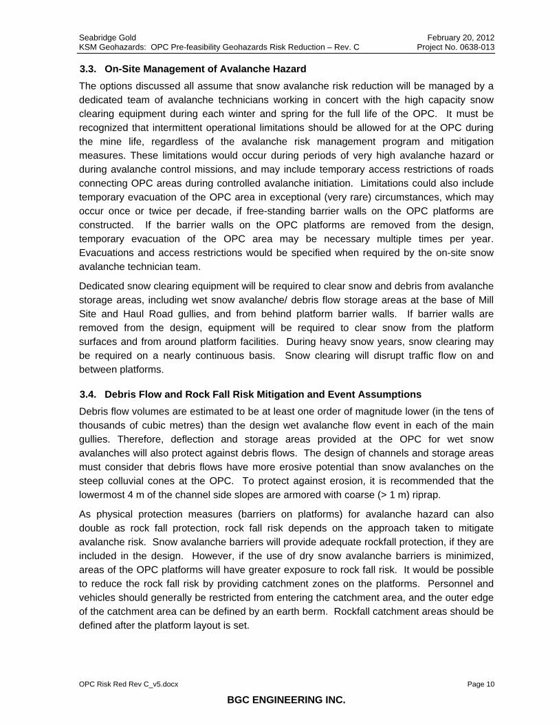
3.3. On-Site Management of Avalanche Hazard The options discussed all assume that snow avalanche risk reduction will be managed by a dedicated team of avalanche technicians working in concert with the high capacity snow clearing equipment during each winter and spring for the full life of the OPC. It must be recognized that intermittent operational limitations should be allowed for at the OPC during the mine life, regardless of the avalanche risk management program and mitigation measures. These limitations would occur during periods of very high avalanche hazard or during avalanche control missions, and may include temporary access restrictions of roads connecting OPC areas during controlled avalanche initiation. Limitations could also include temporary evacuation of the OPC area in exceptional (very rare) circumstances, which may occur once or twice per decade, if free-standing barrier walls on the OPC platforms are constructed. If the barrier walls on the OPC platforms are removed from the design, temporary evacuation of the OPC area may be necessary multiple times per year. Evacuations and access restrictions would be specified when required by the on-site snow avalanche technician team.
Dedicated snow clearing equipment will be required to clear snow and debris from avalanche storage areas, including wet snow avalanche/ debris flow storage areas at the base of Mill Site and Haul Road gullies, and from behind platform barrier walls. If barrier walls are removed from the design, equipment will be required to clear snow from the platform surfaces and from around platform facilities. During heavy snow years, snow clearing may be required on a nearly continuous basis. Snow clearing will disrupt traffic flow on and between platforms.
3.4. Debris Flow and Rock Fall Risk Mitigation and Event Assumptions Debris flow volumes are estimated to be at least one order of magnitude lower (in the tens of thousands of cubic metres) than the design wet avalanche flow event in each of the main gullies. Therefore, deflection and storage areas provided at the OPC for wet snow avalanches will also protect against debris flows. The design of channels and storage areas must consider that debris flows have more erosive potential than snow avalanches on the steep colluvial cones at the OPC. To protect against erosion, it is recommended that the lowermost 4 m of the channel side slopes are armored with coarse (> 1 m) riprap.
As physical protection measures (barriers on platforms) for avalanche hazard can also double as rock fall protection, rock fall risk depends on the approach taken to mitigate avalanche risk. Snow avalanche barriers will provide adequate rockfall protection, if they are included in the design. However, if the use of dry snow avalanche barriers is minimized, areas of the OPC platforms will have greater exposure to rock fall risk. It would be possible to reduce the rock fall risk by providing catchment zones on the platforms. Personnel and vehicles should generally be restricted from entering the catchment area, and the outer edge of the catchment area can be defined by an earth berm. Rockfall catchment areas should be defined after the platform layout is set.

Seabridge Gold February 20, 2012 KSM Geohazards: OPC Pre-feasibility Geohazards Risk Reduction – Rev. C Project No. 0638-013
OPC Risk Red Rev C_v5.docx Page 11
BGC ENGINEERING INC.
4.0 SITE SPECIFIC RISK REDUCTION DESIGN
4.1. General The following sections summarize site-specific pre-feasibility level risk reduction design information to facilitate cost estimation. Drawings 2 and 3 illustrate risk reduction options at each site. This information provides guidance to others who will incorporate the risk reduction structures into the design. BGC requests the opportunity to review the designs to confirm that the design meets the intent of our recommendations.
BGC’s current understanding of the design basis for each area is described, based on meetings and conversations held in February, 2012 involving BGC, Alpine Solutions, Moose Mountain Technical Services, and Bosche Ventures Ltd.
4.2. Primary Crusher Platform The project team has requested two options for geohazard risk reduction. The design decision should be based on a study that compares the capital costs, operating costs, uncertainty and risks associated with each option.
Option 1:
Wall 1 is constructed on the upper platform (elevation 840 m) to protect the Primary Crusher platform from dry snow avalanches and rock fall (Drawing 2). Over the winter, accumulated avalanche snow may fill Mill Site Gully, making it more likely that avalanches will flow over the gully and continue to the Primary Crusher platform. Wall 1 is designed to protect the crusher platform. This option will reduce the likelihood that evacuation of the primary crusher platform will be necessary during high avalanche hazard periods, and reduce the likelihood that the primary crusher or vehicles on the platform are impacted by an avalanche or rockfall.
Wall 1 design criteria are:
• 12 m total wall height.
• Wall designed to resist avalanche debris impact forces provided in Section 5.
• Wall offset 20 m from the cut slope to provide a snow and debris storage area.
• Wall offset 10 m from the fill slope crest to allow permanent access to the snow and debris storage area behind the wall for snow removal and cleaning.
Option 2:
No wall is constructed. Avalanche safety risk is managed by routine evacuation of the facility during periods of high avalanche hazard. It may be possible to design an avalanche-proof bunker within the facility that provides refuge to critical staff during high hazard periods. The design and operation plans should allow for the following:
• Evacuation and possible shutdown of the facility several times per year for several days each time. Shutdown may be caused by high avalanche hazard or during clean up and repair after an avalanche impacts the facility.

Seabridge Gold February 20, 2012 KSM Geohazards: OPC Pre-feasibility Geohazards Risk Reduction – Rev. C Project No. 0638-013
OPC Risk Red Rev C_v5.docx Page 12
BGC ENGINEERING INC.
• Design facilities to resist avalanche debris impact forces provided in Section 5.
• Provide 20 m width snow and rockfall catchment area at the toe of the cut slope.
• Provide a 2 m high earth berm at the limit of the catchment area (Drawing 3). The location of the berm should be approximately the same as ‘Wall 1’.
4.3. Mill Site Gully The Mill Site Gully is located between the Central Platform and Eastern Platform. The apex of Mill Site Gully fan is located between 40 m and 60 m (in elevation) above the platform elevations. It would be possible for a wet snow avalanche or debris flow to runout onto the platforms, particularly the Central Platform, unless a diversion structure is constructed. Additionally, the currently proposed Rock Storage Facility (RSF) fills in the basin between the platforms, which could redirect an avalanche or debris flow onto one of the platforms.
Two risk reduction measures are proposed at the Mill Site Gully, including an excavated, rip-rap protected channel to direct flows away from the platforms, and a snow / debris storage area that can contain the avalanche debris. The channel should be excavated into the native material that composes the fan, and the snow / debris storage area should be provided for in the RSF design. An example of the channel and storage area is shown on Drawing 2, although other configurations may also be acceptable.
The channel should be designed to meet the following criteria:
• Upper extent of channel located near elevation 920 m.
• Channel cross-section at upper extent should tie in to natural channel cross-section, which is about 10 m wide at the base, 50 m wide at the top, and 20 m deep.
• The lower extent of the channel should be at or below elevation 800, and where the slope angle is less than 20°.
• The channel cross-sectional area should be greater than or equal to 600 m2, which is approximately the sectional area of the natural channel.
• Minimum channel depth is 6 m (except at the transition to the channel outlet).
• Expected excavation depth is between 6 and 10 m.
• Lowermost 4 m of channel walls lined with coarse (> 1 m) rip rap for erosion protection for full channel length.
• Slope of channel should be greater than 20°.
• Channel should be constructed before or during platform earthworks construction, and the rip rap erosion protection should be placed as soon as possible.
The snow avalanche storage area should be designed to meet the following criteria:
• Minimum storage volume of 400,000 m3.
• Storage must be provided during all stages of construction and operation. All construction stages of the RSF should provide the required storage volume.

Seabridge Gold February 20, 2012 KSM Geohazards: OPC Pre-feasibility Geohazards Risk Reduction – Rev. C Project No. 0638-013
OPC Risk Red Rev C_v5.docx Page 13
BGC ENGINEERING INC.
• The base of the storage area must be at or below elevation 790 m (20 m below the Eastern Platform).
• The minimum relief should be 20 m between the base and top of the storage area at the perimeter.
• The perimeter of the storage area may be defined by berms that are built up above the surrounding topography or the storage area may be set down into the topography.
4.4. Main Electrical Substation The Main Electrical Substation is located on the northeast corner of the Central Platform. BGC understands from the project team that the substation will be designed to be impacted by rockfall and snow avalanches and buried by snow. Access to the facility while it is buried will be gained through a branch off of the conveyor tunnel. Access to the platform near the substation may be restricted during periods of high avalanche hazard. As such, no additional avalanche protection is required.
4.5. Coarse Ore Stockpile and Conveyors The coarse ore stockpile is located at the center of the Central Platform. A conveyor from the primary crusher drops ore on top of the pile from an elevation of greater than 35 m above the platform elevation. Reclaim tunnels below the stockpile, and below the platform, deliver ore to the conveyor tunnel. The stockpile may be impacted by snow avalanches and rockfall. BGC understands from the project team, that this is acceptable because there are no permanent installations around the stockpile that would be damaged. Snow avalanche risk to personnel and vehicles would be managed by evacuations and access restrictions to the north side of the stockpile during periods of high avalanche hazard.
It is considered unlikely that the conveyor that delivers ore to the top of the stockpile will be impacted by an avalanche due to its 35 m elevation above the platform. However the pillars that support the conveyor must be designed to resist the avalanche impact forces provided in Section 5.
4.6. Conveyor Tunnel Portal The MTT conveyor tunnel portal is located near the center of the Central Platform. This tunnel contains ore conveyors and provides access to the main electrical substation. BGC understands that the tunnel entrance needs to be protected from geohazards at all times, and the risk of the tunnel entrance being buried by snow avalanche debris should be minimized. As requested, two different geohazard protection options are provided that meet this design requirement:
Option 1:
Short tunnel portal protected by parapet wall (Drawing 2).
• 30 m extension of the tunnel portal onto the platform, beyond the cut slope.
Seabridge Gold February 20, 2012 KSM Geohazards: OPC Pre-feasibility Geohazards Risk Reduction – Rev. C Project No. 0638-013
OPC Risk Red Rev C_v5.docx Page 14
BGC ENGINEERING INC.
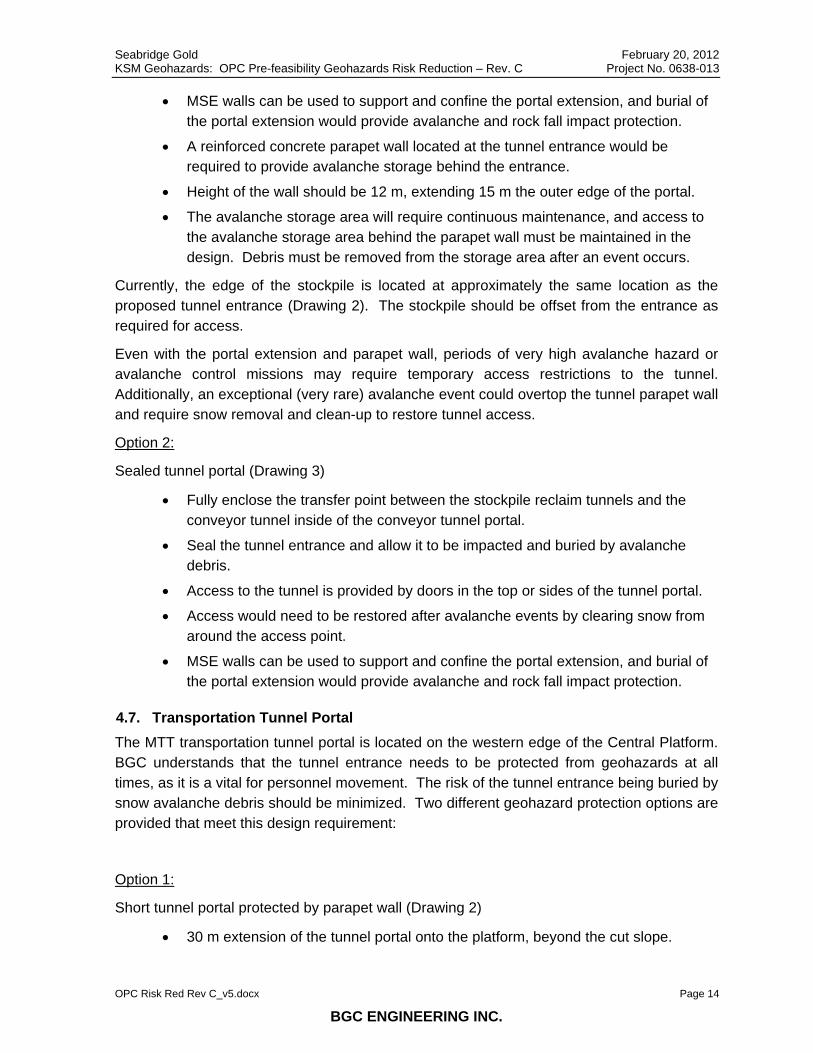
• MSE walls can be used to support and confine the portal extension, and burial of the portal extension would provide avalanche and rock fall impact protection.
• A reinforced concrete parapet wall located at the tunnel entrance would be required to provide avalanche storage behind the entrance.
• Height of the wall should be 12 m, extending 15 m the outer edge of the portal.
• The avalanche storage area will require continuous maintenance, and access to the avalanche storage area behind the parapet wall must be maintained in the design. Debris must be removed from the storage area after an event occurs.
Currently, the edge of the stockpile is located at approximately the same location as the proposed tunnel entrance (Drawing 2). The stockpile should be offset from the entrance as required for access.
Even with the portal extension and parapet wall, periods of very high avalanche hazard or avalanche control missions may require temporary access restrictions to the tunnel. Additionally, an exceptional (very rare) avalanche event could overtop the tunnel parapet wall and require snow removal and clean-up to restore tunnel access.
Option 2:
Sealed tunnel portal (Drawing 3)
• Fully enclose the transfer point between the stockpile reclaim tunnels and the conveyor tunnel inside of the conveyor tunnel portal.
• Seal the tunnel entrance and allow it to be impacted and buried by avalanche debris.
• Access to the tunnel is provided by doors in the top or sides of the tunnel portal.
• Access would need to be restored after avalanche events by clearing snow from around the access point.
• MSE walls can be used to support and confine the portal extension, and burial of the portal extension would provide avalanche and rock fall impact protection.
4.7. Transportation Tunnel Portal The MTT transportation tunnel portal is located on the western edge of the Central Platform. BGC understands that the tunnel entrance needs to be protected from geohazards at all times, as it is a vital for personnel movement. The risk of the tunnel entrance being buried by snow avalanche debris should be minimized. Two different geohazard protection options are provided that meet this design requirement:
Option 1:
Short tunnel portal protected by parapet wall (Drawing 2)
• 30 m extension of the tunnel portal onto the platform, beyond the cut slope.

Seabridge Gold February 20, 2012 KSM Geohazards: OPC Pre-feasibility Geohazards Risk Reduction – Rev. C Project No. 0638-013
OPC Risk Red Rev C_v5.docx Page 15
BGC ENGINEERING INC.
• MSE walls can be used to support and confine the portal extension, and burial of the portal extension would provide avalanche and rock fall impact protection.
• A reinforced concrete parapet wall located at the tunnel entrance would be required to provide avalanche storage behind the entrance.
• Height of the wall should be 12 m , extending 15 m the outer edge of the portal.
• The avalanche storage area will require continuous maintenance, and access to the avalanche storage area behind the parapet wall must be maintained in the design. Debris must be removed from the storage area after an event occurs.
Option 2:
Tunnel portal extension across platform (Drawing 3)
• Extend the tunnel portal approximately 100 m beyond the cut slope, across nearly the full width of the platform.
• Leave a minimum width for platform access between the south edge of the platform and the tunnel portal (assumed to be 10 m in Drawing 3).
• MSE walls can be used to support and confine the portal extension, and burial of the portal extension would provide avalanche and rock fall impact protection.
Periods of very high avalanche hazard or avalanche control missions may require temporary access restrictions to the tunnel, regardless of the chosen option. Additionally, an exceptional (very rare) avalanche event could overtop the tunnel parapet wall (Option 1) or runout beyond the portal extension (Option 2) and require snow removal and clean-up to restore tunnel access.
4.8. Haul Road Gully The Haul Road Gully is located west of the Central Platform. The Central Platform elevation (El 820 m) is approximately 40 m in elevation below the apex of the Haul Road Gully fan. Without a diversion structure it would be possible for wet snow avalanches and debris flows to flow onto the Central Platform. Additionally, the proposed ultimate toe of the Mitchell Rock Storage Facility (RSF) infills over and raises the elevation of the Haul Road Gully fan. The RSF could re-direct flows back onto the Central Platform, unless a snow / debris storage area is provided for in the RSF design.
Two risk reduction measures are proposed at the Haul Road Gully, including an excavated, rip-rap protected channel to direct flows away from the Central Platform, and a snow / debris storage area. The channel should be excavated into the native material that composes the fan, and the snow and debris storage area should be provided for in the RSF design. An example of the channel and storage area is shown on Drawing 2, although other configurations may also be acceptable.
The channel should be designed to meet the following criteria:
• Upper extent of channel located near elevation 870 m.
Seabridge Gold February 20, 2012 KSM Geohazards: OPC Pre-feasibility Geohazards Risk Reduction – Rev. C Project No. 0638-013
OPC Risk Red Rev C_v5.docx Page 16
BGC ENGINEERING INC.
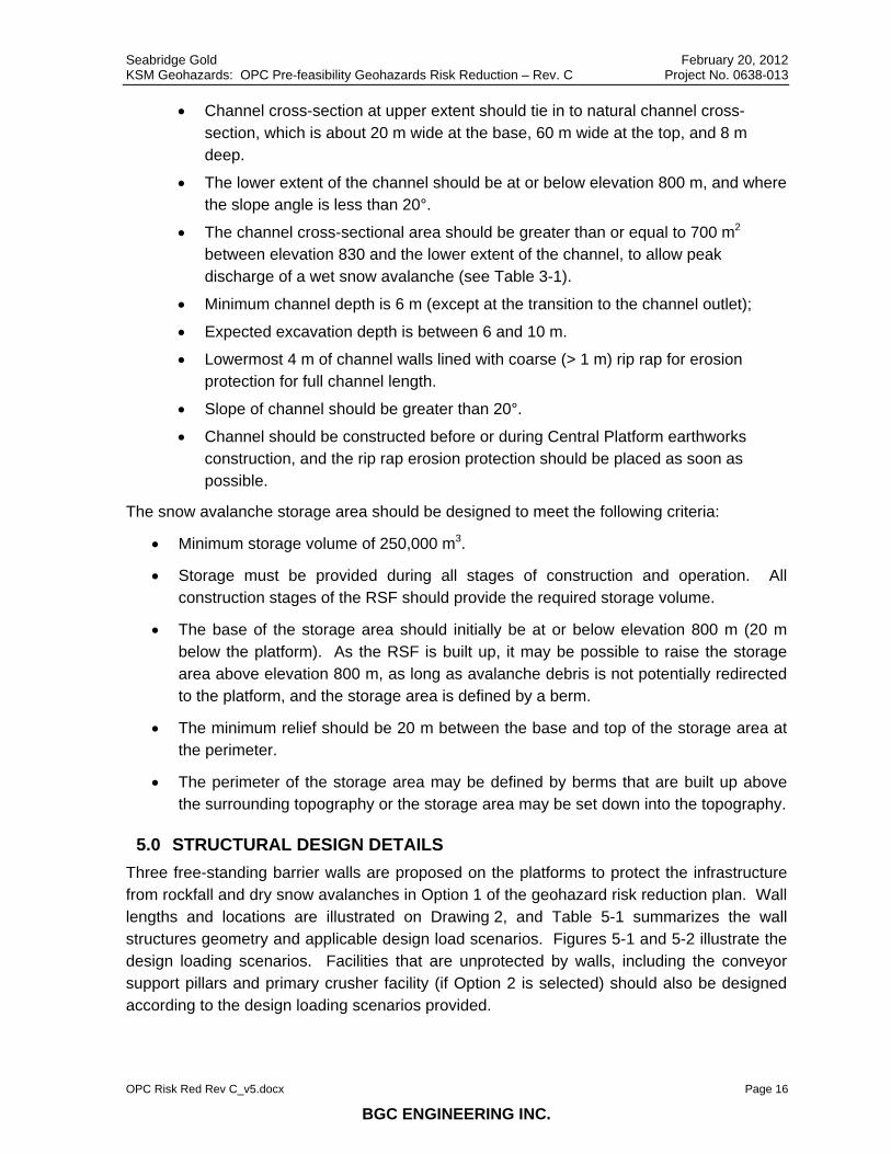
• Channel cross-section at upper extent should tie in to natural channel cross-section, which is about 20 m wide at the base, 60 m wide at the top, and 8 m deep.
• The lower extent of the channel should be at or below elevation 800 m, and where the slope angle is less than 20°.
• The channel cross-sectional area should be greater than or equal to 700 m2 between elevation 830 and the lower extent of the channel, to allow peak discharge of a wet snow avalanche (see Table 3-1).
• Minimum channel depth is 6 m (except at the transition to the channel outlet);
• Expected excavation depth is between 6 and 10 m.
• Lowermost 4 m of channel walls lined with coarse (> 1 m) rip rap for erosion protection for full channel length.
• Slope of channel should be greater than 20°.
• Channel should be constructed before or during Central Platform earthworks construction, and the rip rap erosion protection should be placed as soon as possible.
The snow avalanche storage area should be designed to meet the following criteria:
• Minimum storage volume of 250,000 m3.
• Storage must be provided during all stages of construction and operation. All construction stages of the RSF should provide the required storage volume.
• The base of the storage area should initially be at or below elevation 800 m (20 m below the platform). As the RSF is built up, it may be possible to raise the storage area above elevation 800 m, as long as avalanche debris is not potentially redirected to the platform, and the storage area is defined by a berm.
• The minimum relief should be 20 m between the base and top of the storage area at the perimeter.
• The perimeter of the storage area may be defined by berms that are built up above the surrounding topography or the storage area may be set down into the topography.
5.0 STRUCTURAL DESIGN DETAILS Three free-standing barrier walls are proposed on the platforms to protect the infrastructure from rockfall and dry snow avalanches in Option 1 of the geohazard risk reduction plan. Wall lengths and locations are illustrated on Drawing 2, and Table 5-1 summarizes the wall structures geometry and applicable design load scenarios. Figures 5-1 and 5-2 illustrate the design loading scenarios. Facilities that are unprotected by walls, including the conveyor support pillars and primary crusher facility (if Option 2 is selected) should also be designed according to the design loading scenarios provided.

Seabridge Gold February 20, 2012 KSM Geohazards: OPC Pre-feasibility Geohazards Risk Reduction – Rev. C Project No. 0638-013
OPC Risk Red Rev C_v5.docx Page 17
BGC ENGINEERING INC.
Avalanche barrier walls are typically constructed using reinforced concrete. A second option may be to construct the wall using geosynthetic reinforced soil (GRS). GRS uses layers of well compacted, granular soil, and closely spaced (typically on the order of 0.3 m spacing) bi-axial geosynthetic fabric or grid. The GRS forms a composite mass that behaves as a gravity retaining wall. The GRS barrier wall can have vertical sides. GRS would occupy a larger footprint on the platform than a reinforced concrete wall, but may be a less expensive alternative as it does not use concrete and would not require ground anchorage. Preliminary calculations show that the required width of the barrier is on the order of 9 m to resist sliding caused by the avalanche impact. Further work would be required to evaluate the feasibility of this option. BGC has used GRS on previous projects for rockfall and debris flow barriers, however using shorter wall heights and different loading conditions.
For dry avalanches, pressures are based on Size 3 avalanches impacting the walls according to two different load scenarios, depending on whether the storage area behind the wall has been filled partially with avalanche debris (or not). Load Scenario 1 considers an impact pressure from the leading edge at the base of the wall, and stagnation pressure for the trailing mass that climbs the wall after initial impact. Load Scenario 2 considers the condition when the storage area behind a wall is half full, and an additional avalanche occurs. This situation allows for static avalanche load on the lower half of the wall, and a short duration impact and stagnation load on the upper half of the wall. Snow and rock debris removal will require continuous availability of front end loaders and dump trucks throughout winter and spring.
It is possible that the impact forces associated with an exceptional event would exceed the forces provided in this section. Inclusion of barrier walls on the platforms (option 1) helps to mitigate the risks associated with an exceptional event, because the wall receives the direct impact and will likely prevent destruction of the facilities, even if the wall itself is severely damaged or destroyed. If barrier walls are removed from the platforms (option 2), the facilities themselves will receive the direct impact. As such, it is recommended that a relatively higher safety factor be applied to the facility design for avalanche impact where barrier walls are omitted.

SeabridKSM G
OPC Ris
Table
Wall
Wall 1
Wall 2
Wall 3
Notes: Hi = Hei
Pi = Initi
dge Gold Geohazards: O
sk Red Rev C_v
5-1 Summa
Ar
Primary C
Conveyor Parapet W
TransportaParapet W
ight of initial impa
ial impact pressu
PPP
PC Pre-feasibi
5.docx
ary of OPC G
rea Protected
Crusher, Uppe
Tunnel PortaWall
ation Tunnel Wall
act
ure
Figu
Pi = initial imPa = stagnatPa = 0.4 x P
ility Geohazard
BGC EN
Geohazard R
d Le
er Bench
al
Portal
re 5-1 – Aval
mpact pressution pressurei
ds Risk Reduct
NGINEERIN
Risk Reductio
ength (m)
He
300
60
95
lanche Impac
ure e
tion – Rev. C
NG INC.
on Wall Struc
ight (H) (m)
R
12
12
12
ct on Wall (N
P
ctures – Opt
Reference DeLoad Figur
3-1, 3-2
3-1, 3-2
3-1, 3-2
NTS)
Hi
H
February 20Project No. 063
P
ion 1
esign re
Hi
(m)
2
2
2
0, 2012 38-013
Page 18
Pi
(kPa)
200
200
200

Seabridge Gold February 20, 2012 KSM Geohazards: OPC Pre-feasibility Geohazards Risk Reduction – Rev. C Project No. 0638-013
OPC Risk Red Rev C_v5.docx Page 19
BGC ENGINEERING INC.
Figure 5-2 Avalanche Impact Overtop of Deposit (NTS)
H/2
Hi
Varies Pa
Pi
PT
PB
PB = 1.0 kPa x H /2 PT =0

Seabridge Gold February 20, 2012 KSM Geohazards: OPC Pre-feasibility Geohazards Risk Reduction – Rev. C Project No. 0638-013
OPC Risk Red Rev C_v5.docx Page 20
BGC ENGINEERING INC.
6.0 RISK REDUCTION COMPONENTS SUMMARY
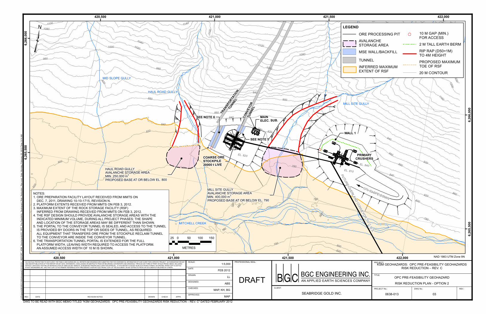
Table 6-1 is a summary of the elements at risk and the proposed risk reduction measures to reduce risk to ‘moderate’. The table compares two options that have been presented in previous sections of the report. Option 1 is illustrated on Drawing 2. Option 2 is illustrated on Drawing 3. One of the two options should be selected for each element at risk. It is acceptable to select option 1 for an element at risk, and option 2 for a different element at risk. Risk reduction measures in the ‘Safety’ category reduce the likelihood that personnel are injured or killed. Risk reduction measures in the ‘Economic’ category reduce the likelihood that facilities or equipment are damaged by the geohazards. Many of the risk reduction measures reduce both ‘Safety’ and ‘Economic’ risks. Economic risk from loss of production time caused by evacuation or event clean-up is not considered as it is assumed that the facility can operate with an ore stockpile at the processing plant so that short shut down of the crushing and transportation operation does not affect mine production.
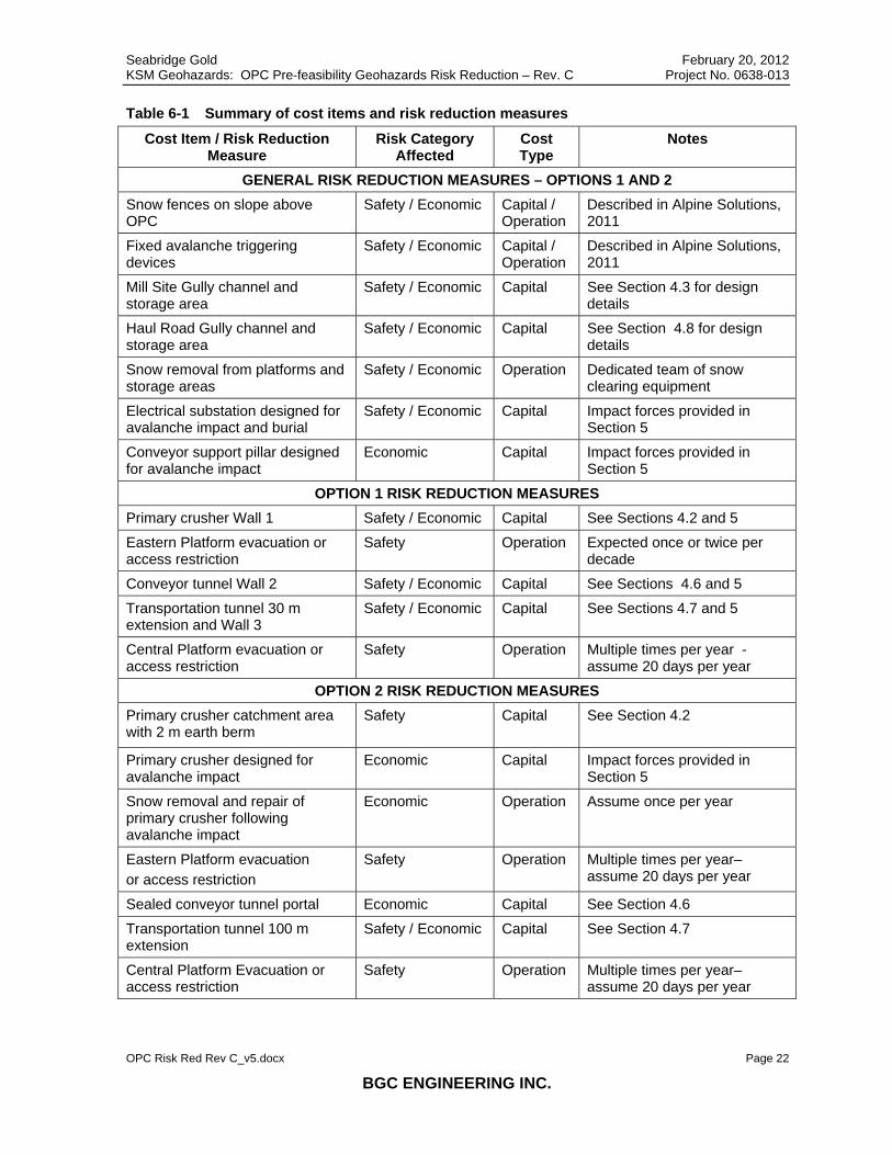
Table 6-2 is a summary of the risk reduction measures and cost items. It is intended to aid cost estimation. ‘Capital’ costs refer to the cost of infrastructure constructed concurrently with the OPC facilities. ‘Operational’ costs refer to annual cost of maintenance, and the costs associated with OPC facility shutdowns and infrastructure repairs caused by geohazards after the OPC is operating.

Seabridge Gold February 20, 2012 KSM Geohazards: OPC Pre-feasibility Geohazards Risk Reduction – Rev. C Project No. 0638-013
OPC Risk Red Rev C_v5.docx Page 21
BGC ENGINEERING INC.
Table 6-1 Summary of elements at risk and risk reduction options 1 and 2 Element at Risk Risk
Category Risk Reduction Measures:
Option 1 Risk Reduction Measures:
Option 2 All personnel and Infrastructure
Safety / Economic
Snow fences; fixed avalanche triggering; snow removal from storage areas; channels and storage areas at gully outlet
Snow fences; fixed avalanche triggering; snow removal from storage areas; channels and storage areas at gully outlet
Personnel on Eastern Platform
Safety Wall 1; evacuation during exceptional snow storm event
2 m earth berm and storage area; evacuation multiple times per year
Personnel on Central Platform
Safety evacuation multiple times per year during high avalanche hazard periods;
evacuation multiple times per year during high avalanche hazard periods;
Personnel at transportation tunnel entrance
Safety Wall 2; 30 m tunnel extension; evacuation during exceptional storm event
100 m tunnel extension; evacuation during exceptional storm event
Primary crusher facility and equipment
Economic Wall 1 2 m earth berm and storage area; facility and equipment designed for avalanche impact
Main electrical substation
Economic Designed for avalanche impact and burial; entrance through conveyor tunnel
Designed for avalanche impact and burial; entrance through conveyor tunnel
Coarse ore stockpile and conveyor
Economic Conveyor 35 m above platform; support pillars designed for avalanche impact
Conveyor 35 m above platform; support pillars designed for avalanche impact
Conveyor tunnel entrance
Economic Wall 3 Sealed conveyor tunnel portal with transfer equipment inside
Transportation tunnel entrance
Economic Wall 2; 30 m tunnel extension 100 m tunnel extension;
Seabridge Gold February 20, 2012 KSM Geohazards: OPC Pre-feasibility Geohazards Risk Reduction – Rev. C Project No. 0638-013
OPC Risk Red Rev C_v5.docx Page 22
BGC ENGINEERING INC.
Table 6-1 Summary of cost items and risk reduction measures
Cost Item / Risk Reduction Measure
Risk Category Affected
Cost Type
Notes
GENERAL RISK REDUCTION MEASURES – OPTIONS 1 AND 2 Snow fences on slope above OPC
Safety / Economic Capital / Operation
Described in Alpine Solutions, 2011
Fixed avalanche triggering devices
Safety / Economic Capital / Operation
Described in Alpine Solutions, 2011
Mill Site Gully channel and storage area
Safety / Economic Capital See Section 4.3 for design details
Haul Road Gully channel and storage area
Safety / Economic Capital See Section 4.8 for design details
Snow removal from platforms and storage areas
Safety / Economic Operation Dedicated team of snow clearing equipment
Electrical substation designed for avalanche impact and burial
Safety / Economic Capital Impact forces provided in Section 5
Conveyor support pillar designed for avalanche impact
Economic Capital Impact forces provided in Section 5
OPTION 1 RISK REDUCTION MEASURES Primary crusher Wall 1 Safety / Economic Capital See Sections 4.2 and 5
Eastern Platform evacuation or access restriction
Safety Operation Expected once or twice per decade
Conveyor tunnel Wall 2 Safety / Economic Capital See Sections 4.6 and 5
Transportation tunnel 30 m extension and Wall 3
Safety / Economic Capital See Sections 4.7 and 5
Central Platform evacuation or access restriction
Safety Operation Multiple times per year - assume 20 days per year
OPTION 2 RISK REDUCTION MEASURES Primary crusher catchment area with 2 m earth berm
Safety Capital See Section 4.2
Primary crusher designed for avalanche impact
Economic Capital Impact forces provided in Section 5
Snow removal and repair of primary crusher following avalanche impact
Economic Operation Assume once per year
Eastern Platform evacuation or access restriction
Safety Operation Multiple times per year– assume 20 days per year
Sealed conveyor tunnel portal Economic Capital See Section 4.6
Transportation tunnel 100 m extension
Safety / Economic Capital See Section 4.7
Central Platform Evacuation or access restriction
Safety Operation Multiple times per year– assume 20 days per year

Seabridge Gold February 20, 2012 KSM Geohazards: OPC Pre-feasibility Geohazards Risk Reduction – Rev. C Project No. 0638-013
OPC Risk Red Rev C_v5.docx Page 23
BGC ENGINEERING INC.
7.0 RECOMMENDATIONS
The estimated residual risk is based on the available, preliminary information. The risk estimate and risk reduction measures should be re-evaluated as more information becomes available in future design stages and during operation, including:
• additional information related to avalanche, rockfall, and debris flow intensity and frequency; and
• updates to the proposed OPC layout and layout changes that occur during different operation phases.
The design of avalanche protection measures at the OPC depends on the assessed design avalanche events, which is in turn dependent on the overall avalanche risk reduction plan for the slopes above the OPC. As this plan is adjusted, risk mitigation measures at the OPC should be revisited.
The economic risk associated with Option 2 (no barrier walls) has not been quantified because it depends heavily on details of the facility design and ore processing system design which have not been provided at this design stage. ‘Major’, ‘Severe’, or ‘Catastrophic’ economic consequences (resulting in ‘High’ or ‘Very High’ risk) could be caused by an avalanche that severely damages or destroys the primary crusher, or other critical structure. If walls are removed from the design, the designers must consider that the facilities themselves will be impacted by the full avalanche force, potentially several times in the same season. Also, the facilities may be impacted by an exceptional event (very rare) that exceeds the impact forces that have been provided in section 5.
An exceptional event (very rare) could exceed the impact forces provided in section 5. This should be accounted for in the design by using standard safety factors in the design of the barrier walls (option 1). Higher than standard safety factors should be applied to avalanche impact design at facilities where the barrier walls are omitted and avalanches are expected to have direct impact (option 2).
To protect worker safety and constructed works, construction schedule planning will need to integrate the construction plan and schedule for geohazard risk reduction measures. BGC and Alpine Solutions recommend that ongoing geohazard risk reduction input be retained as the project advances from pre-feasibility design, especially for the fixed avalanche explosive control program.
A cost comparison analysis of the two presented options is recommended. The cost comparison should consider the capital cost versus the operational costs, opportunity costs, and economic risks from OPC shutdowns, facility damage, and clean up associated with each option. The analysis should account for the uncertainty associated with each option.

Seabridge Gold February 20, 2012 KSM Geohazards: OPC Pre-feasibility Geohazards Risk Reduction – Rev. C Project No. 0638-013
OPC Risk Red Rev C_v5.docx Page 24
BGC ENGINEERING INC.
8.0 LIMITATIONS
This memorandum provides descriptions of conceptual risk reduction measures to reduce existing geohazard risk to the OPC. At the time of preparation of this memorandum, design magnitudes and frequencies for geohazards such as debris flows and avalanches reaching the OPC had only been examined at a preliminary level and estimates used in this work are therefore conservative. While considered sufficient for inclusion in pre-feasibility geometric layout of the OPC and for cost estimate allowances for these measures, further refinement of potential geohazard event magnitudes, frequencies, and design loads, as well as refinement of vulnerability criteria for infrastructure subject to geohazards, will be required for feasibility level design. As the project design advances, facility layout may change which will require re-evaluation or optimization of geohazard reduction options. Also, as up slope avalanche management plans develop, design events at the OPC may change, requiring re-assessment of risk reduction measures at the OPC.
The key in conceptualizing the risk reduction measures is to reach a confidence that High and Very High risks are reduced to Moderate and therefore constitute a risk level that has been considered tolerable by Seabridge. Complete elimination of risks cannot be achieved due to the inherent uncertainties in the geohazard processes discussed in this memorandum.
The following information is not provided in this memorandum:
• Detailed geometric design of proposed risk reduction measures.
• Prescriptions of earthworks, construction schedules and operation and maintenance issues.
• Detailed active avalanche management plan.
In addition, this memo does not address issues related to the timeline to build and install all fixed protection measures. These are important considering the requirement for all risk reduction measures to act together to provide an integrated risk reduction strategy for all parties working on aspects of the OPC and surrounding infrastructure. Previous experience with similar projects suggests:
• Snow clearing on the north side of OPC facilities is potentially a significant issue and will require careful planning to ensure adequate snow clearing equipment capacity is available and has sufficient access for their work. This is critical to the protection of OPC facilities.
• Careful integration of facility construction with geohazard protection measures construction will be required to minimize risk to personnel and facilities during construction.
• An integrated risk awareness program will be required in which all workers and supervisors are trained and site access is strictly controlled during avalanche season.

Seabridge Gold February 20, 2012 KSM Geohazards: OPC Pre-feasibility Geohazards Risk Reduction – Rev. C Project No. 0638-013
OPC Risk Red Rev C_v5.docx Page 25
BGC ENGINEERING INC.
• Complete build out of the numerous fixed avalanche exploders may take 5 years or more.
• Significant access limitations could occur during the winter months that could create delays to construction.
Skilled avalanche technicians with extensive experience will be essential for successful application of this integrated avalanche risk reduction strategy.

Seabridge Gold February 20, 2012 KSM Geohazards: OPC Pre-feasibility Geohazards Risk Reduction – Rev. C Project No. 0638-013
OPC Risk Red Rev C_v5.docx Page 26
BGC ENGINEERING INC.
9.0 CLOSURE
BGC and Alpine Solutions prepared this document for the account of Seabridge Gold. The material in it reflects the judgment of BGC and Alpine Solutions staff in light of the information available to BGC at the time of document preparation. Any use which a third party makes of this document or any reliance on decisions to be based on it is the responsibility of such third parties. BGC and Alpine Solutions accept no responsibility for damages, if any, suffered by any third party as a result of decisions made or actions based on this document.
As a mutual protection to our client, the public, and ourselves, all documents and drawings are submitted for the confidential information of our client for a specific project. Authorization for any use and/or publication of this document or any data, statements, conclusions or abstracts from or regarding our documents and drawings, through any form of print or electronic media, including without limitation, posting or reproduction of same on any website, is reserved pending BGC’s and Alpine Solutions written approval. If this document is issued in an electronic format, an original paper copy is on file at BGC and that copy is the primary reference with precedence over any electronic copy of the document, or any extracts from our documents published by others.
Yours sincerely,
BGC ENGINEERING INC. per:
Alex Strouth, M.A.Sc., P.E. Brian Gould, P.Eng. Geological Engineer (BGC Engineering) Senior Avalanche Specialist (Alpine Solutions)
Reviewed by:
Mark Pritchard, M.Sc., P.Eng. Senior Geotechnical Engineer (BGC Engineering)
Attach: Drawing 1 OPC Pre-feasibility Geohazards Risk Reduction – General Arrangement Drawing 2 OPC Pre-feasibility Geohazards Risk Reduction Plan – Option 1 Drawing 3 OPC Pre-feasibility Geohazards Risk Reduction Plan – Option 2

Seabridge Gold February 20, 2012 KSM Geohazards: OPC Pre-feasibility Geohazards Risk Reduction – Rev. C Project No. 0638-013
OPC Risk Red Rev C_v5.docx Page 27
BGC ENGINEERING INC.
REFERENCES Alpine Solutions, 2011. Active Avalanche Management Plan for the KSM Project. Project memorandum. Report prepared by Alpine Solutions Avalanche Services for BGC Engineering Inc. and Seabridge Gold, dated May 4, 2011.
BGC, 2010a. KSM Project Preliminary Geohazard and Risk Assessment. Final Draft Report. Report prepared by BGC Engineering Inc. for Seabridge Gold, dated December 10, 2010. 127 pp.
BGC, 2010b. Preliminary Geohazards Risk Reduction Concepts – DRAFT. Report prepared by BGC Engineering Inc. for Seabridge, issued December 24, 2010.
BGC, 2011a. KSM Geohazards: OPC Pre-feasibility Geohazards Risk Reduction – Rev. A. Report prepared by BGC Engineering Inc. for Seabridge, issued March 30, 2011.
BGC, 2011b. KSM Geohazards: OPC Pre-feasibility Geohazards Risk Reduction – Rev. B. Report prepared by BGC Engineering Inc. for Seabridge, issued April 21, 2011.
BGC, 2011c. KSM Project Geohazard and Risk Assessment. Revision B. Report prepared by BGC Engineering Inc. for Seabridge Gold, dated August 24, 2011.
Jakob, M. 2005. A Size Classification for Debris Flows. Engineering Geology: 79: 151-161.
McClung, D.M. and Schaerer, P.A, 2006. The Avalanche Handbook. Seattle, WA, The Mountaineers.
Mears, 1992, Snow-Avalanche Hazard Analysis for Land Use Planning and Engineering. Colorado Geological Survey Bulletin 49. Dept. of Natural Resources, Denver, Colorado
CAA 2002. Canadian Avalanche Association (CAA). 2002. Guidelines for Snow Avalanche Risk Determination and Mapping in Canada. McClung, D.M., Stethem, P. A. Schaerer, and J.B. Jamieson (eds.), Canadian Avalanche Association, 23 pp.

Seabridge Gold February 20, 2012 KSM Geohazards: OPC Pre-feasibility Geohazards Risk Reduction – Rev. C Project No. 0638-013
OPC Risk Red Rev C_v5.docx
BGC ENGINEERING INC.
DRAWINGS

TRANSP
ORTATIO
N TUNNEL
CONV
EYOR
TUNN
EL
FUTURE OVERLAND CONVEYOR TO C.O.S.
!
MAIN ELEC. SUB.
!
COARSE ORESTOCKPILE20000 t LIVE
PORTAL
HAUL ROAD GULLYMILL SITE GULLY
MID SLOPE GULLY
MITCHELL CREEK
EL. 820EL. 840EL. 810
!
PRIMARYCRUSHERS
11001200
1000
1300
1400
1500
900
1600
1700
700
1800
1900
1100
900
900
1000
900
900
419,500
419,500
420,000
420,000
420,500
420,500
421,000
421,000
421,500
421,500
422,000
422,000
422,500
422,500 423,000
423,0
00
6,265
,000
6,265
,500
6,265
,500
6,266
,000
6,266
,000
6,266
,500
6,266
,500
6,267,000
6,267
,000
100 0 100 200
METRES
PROJECT:
TITLE:
PROJECT No.: DWG No.: REV.:
KSM GEOHAZARDS: OPC PRE-FEASIBILITY GEOHAZARDSRISK REDUCTION – REV. C
OPC PRE-FEASIBILITY GEOHAZARDGENERAL ARANGEMENT
0638-013 01CLIENT:
SEABRIDGE GOLD INC.
B G C B G C E N G IN E E R IN G IN C .AN APPLIED EARTH SCIENCES COMPANY
SCALE:
DATE:
DRAWN:
DESIGNED:
CHECKED:
APPROVED:
PROFESSIONAL SEAL:1:10,000FEB 2012
LL
ABSMAP, KH, BG
MAP
DRAFTREV. DATE REVISION NOTES DRAWN CHECK APPR.
AS A MUTUAL PROTECTION TO OUR CLIENT, THE PUBLIC, AND OURSELVES, ALL REPORTS AND DRAWINGS ARE SUBMITTED FOR THE CONFIDENTIAL INFORMATION OF OUR CLIENT FOR A SPECIFIC PROJECT. AUTHORIZATION FOR ANYUSE AND/OR PUBLICATION OF THIS REPORT OR ANY DATA, STATEMENTS, CONCLUSIONS OR ABSTRACTS FROM OR REGARDING OUR REPORTS AND DRAWINGS, THROUGH ANY FORM OF PRINT OR ELECTRONIC MEDIA, INCLUDINGWITHOUT LIMITATION, POSTING OR REPRODUCTION OF SAME ON ANY WEBSITE, IS RESERVED PENDING BGC’S WRITTEN APPROVAL. IF THIS REPORT IS ISSUED IN AN ELECTRONIC FORMAT, AN ORIGINAL PAPER COPY IS ON FILEAT BGC ENGINEERING INC. AND THAT COPY IS THE PRIMARY REFERENCE WITH PRECEDENCE OVER ANY ELECTRONIC COPY OF THE DOCUMENT, OR ANY EXTRACTS FROM OUR DOCUMENTS PUBLISHED BY OTHERS.
X:\Pr
ojects
\0638
\013\W
orksp
ace\2
0120
131_
REPO
RT_K
SM_G
eoha
zards
\01_O
PC P
RE-FE
ASIBI
LILTY
_GEN
ERAL
ARAN
GEME
NT.m
xd D
ate: M
onda
y, Fe
bruary
20, 2
012 T
ime:
9:13 A
M
DWG TO BE READ WITH BGC MEMO TITLED "KSM GEOHAZARDS: OPC PRE-FEASIBILITY GEOHAZARDS RISK REDUCTION – REV. C" DATED FEBRUARY 2012
³
NAD 1983 UTM Zone 9N
100 0 100 200 30050
METRES
LEGENDORE PROCESSING PITAVALANCHE STORAGE AREAMSE WALL/BACKFILLTUNNELINFERRED MAXIMUM EXTENT OF RSF
BARRIER WALL(12 M HIGH)RIP RAP (D50=1M) TO 4M HEIGHTPROPOSED MAXIMUM TOE OF RSF100 M CONTOUR20 M CONTOUR
NOTES:1. ORE PREPARATION FACILITY LAYOUT RECEIVED FROM MMTS ON DEC. 7, 2011, DRAWING 10-10-1715, REVISION N.2. PLATFORM EXTENTS RECEIVED FROM MMTS ON FEB 3, 2012.3. MAXIMUM EXTENT OF THE ROCK STORAGE FACILITY (RSF) INFERRED FROM DRAWING RECEIVED FROM MMTS ON FEB 3, 2012.4. RISK REDUCTION PLAN OPTION 1 IS SHOWN (SEE DRAWING 2). OPTION 2 IS SHOWN ON DRAWING 3.

TRANSP
ORTATIO
N
TUNNEL
CONV
EYOR
TUNN
EL
FUTURE OVERLAND CONVEYOR TO C.O.S.
!
MAIN ELEC. SUB.
!
COARSE ORESTOCKPILE20000 t LIVE
10% SLOPE DOWN
PORTAL
PRIMARYCRUSHERS
HAUL ROAD GULLY
MILL SITE GULLY
MID SLOPE GULLY
MITCHELL CREEK
EL. 820
EL. 840EL. 810
!
WALL 1!
WALL 2
!
WALL 3
!
HAUL ROAD GULLYAVALANCHE STORAGE AREAMIN. 250,000 m3
PROPOSED BASE AT OR BELOW EL. 800
!
MILL SITE GULLYAVALANCHE STORAGE AREAMIN. 400,000 m3
PROPOSED BASE AT OR BELOW EL. 790
960
980
940
104010201000
920
900880
860
1060
760
1080
1100
1120
1140
1160
840
820
780
800
1180
1200
1220
740
1240
1260
940
780760
860
800
760
1220
820
920
1140
1200
760
880
780
840
840
820
820
780
760
760
800
760
1100
900
780
760
820
1080
820
760
800
420,500
420,500
421,000
421,000
421,500
421,500
422,000
422,000
6,265
,500
6,265
,500
6,266
,000
6,266
,000
100 0 100 200
METRES
PROJECT:
TITLE:
PROJECT No.: DWG No.: REV.:
KSM GEOHAZARDS: OPC PRE-FEASIBILITY GEOHAZARDSRISK REDUCTION – REV. C
OPC PRE-FEASIBILITY GEOHAZARDRISK REDUCTION PLAN - OPTION 1
0638-013 02CLIENT:
SEABRIDGE GOLD INC.
B G C B G C E N G IN E E R IN G IN C .AN APPLIED EARTH SCIENCES COMPANY
SCALE:
DATE:
DRAWN:
DESIGNED:
CHECKED:
APPROVED:
PROFESSIONAL SEAL:1:5,000FEB 2012
LL
ABSMAP, KH, BG
MAP
DRAFTREV. DATE REVISION NOTES DRAWN CHECK APPR.
AS A MUTUAL PROTECTION TO OUR CLIENT, THE PUBLIC, AND OURSELVES, ALL REPORTS AND DRAWINGS ARE SUBMITTED FOR THE CONFIDENTIAL INFORMATION OF OUR CLIENT FOR A SPECIFIC PROJECT. AUTHORIZATION FOR ANYUSE AND/OR PUBLICATION OF THIS REPORT OR ANY DATA, STATEMENTS, CONCLUSIONS OR ABSTRACTS FROM OR REGARDING OUR REPORTS AND DRAWINGS, THROUGH ANY FORM OF PRINT OR ELECTRONIC MEDIA, INCLUDINGWITHOUT LIMITATION, POSTING OR REPRODUCTION OF SAME ON ANY WEBSITE, IS RESERVED PENDING BGC’S WRITTEN APPROVAL. IF THIS REPORT IS ISSUED IN AN ELECTRONIC FORMAT, AN ORIGINAL PAPER COPY IS ON FILEAT BGC ENGINEERING INC. AND THAT COPY IS THE PRIMARY REFERENCE WITH PRECEDENCE OVER ANY ELECTRONIC COPY OF THE DOCUMENT, OR ANY EXTRACTS FROM OUR DOCUMENTS PUBLISHED BY OTHERS.
X:\Pr
ojects
\0638
\013\W
orksp
ace\2
0120
131_
REPO
RT_K
SM_G
eoha
zards
\02_O
PC_P
re-Fe
asibi
lity_G
eoha
zard_
Risk
_Red
uctio
n_Pla
n.mxd
Date
: Mon
day,
Febru
ary 20
, 201
2 Tim
e: 9:1
3 AM
DWG TO BE READ WITH BGC MEMO TITLED "KSM GEOHAZARDS: OPC PRE-FEASIBILITY GEOHAZARDS RISK REDUCTION – REV. C" DATED FEBRUARY 2012
³
NAD 1983 UTM Zone 9N
50 0 50 100 15025
METRES
LEGENDORE PROCESSING PITAVALANCHE STORAGE AREAMSE WALL/BACKFILLTUNNELINFERRED MAXIMUM EXTENT OF RSF
10 M GAP (MIN.) FOR ACCESS TO CLEANBARRIER WALL(12 M HIGH)RIP RAP (D50=1M) TO 4M HEIGHTPROPOSED MAXIMUM TOE OF RSF20 M CONTOUR
NOTES:1. ORE PREPARATION FACILITY LAYOUT RECEIVED FROM MMTS ON DEC. 7, 2011, DRAWING 10-10-1715, REVISION N.2. PLATFORM EXTENTS RECEIVED FROM MMTS ON FEB 3, 2012.3. WALLS 1, 2, AND 3 MAY BE REINFORCED CONCRETE OR REINFORCED SOIL.4. MAXIMUM EXTENT OF THE ROCK STORAGE FACILITY (RSF) INFERRED FROM DRAWING RECEIVED FROM MMTS ON FEB 3, 2012.5. THE RSF DESIGN SHOULD PROVIDE AVALANCHE STORAGE AREAS WITH THE INDICATED MINIMUM VOLUME, DURING ALL PROJECT PHASES; THE SHAPE AND LOCATION OF THE STORAGE AREAS MAY BE DIFFERENT THAN SHOWN.6. THE COARSE ORE STOCKPILE MAY NEED TO BE RELOCATED ON THE PLATFORM TO PROVIDE SUFFICIENT ACCESS WIDTH BETWEEN THE STOCKPILE AND TUNNEL PORTALS.
TRANSP
ORTATIO
N
TUNNEL
CONV
EYOR
TUNN
EL
FUTURE OVERLAND CONVEYOR TO C.O.S.
!
MAIN ELEC. SUB.
!
COARSE ORESTOCKPILE20000 t LIVE
10% SLOPE DOWN
PORTAL
PRIMARYCRUSHERS
HAUL ROAD GULLY
MILL SITE GULLY
MID SLOPE GULLY
MITCHELL CREEK
EL. 820
EL. 840EL. 810
!
WALL 1!
SEE NOTE 5
!
SEE NOTE 6
!
HAUL ROAD GULLYAVALANCHE STORAGE AREAMIN. 250,000 m3
PROPOSED BASE AT OR BELOW EL. 800
!
MILL SITE GULLYAVALANCHE STORAGE AREAMIN. 400,000 m3
PROPOSED BASE AT OR BELOW EL. 790
960
980
940
104010201000
920
900880
860
1060
760
1080
1100
1120
1140
1160
840
820
780
800
1180
1200
1220
740
1240
1260
940
780760
860
800
760
1220
820
920
1140
1200
760
880
780
840
840
820
820
780
760
760
800
760
1100
900
780
760
820
1080
820
760
800
420,500
420,500
421,000
421,000
421,500
421,500
422,000
422,000
6,265
,500
6,265
,500
6,266
,000
6,266
,000
100 0 100 200
METRES
PROJECT:
TITLE:
PROJECT No.: DWG No.: REV.:
KSM GEOHAZARDS: OPC PRE-FEASIBILITY GEOHAZARDSRISK REDUCTION – REV. C
OPC PRE-FEASIBILITY GEOHAZARDRISK REDUCTION PLAN - OPTION 2
0638-013 03CLIENT:
SEABRIDGE GOLD INC.
B G C B G C E N G IN E E R IN G IN C .AN APPLIED EARTH SCIENCES COMPANY
SCALE:
DATE:
DRAWN:
DESIGNED:
CHECKED:
APPROVED:
PROFESSIONAL SEAL:1:5,000FEB 2012
LL
ABSMAP, KH, BG
MAP
DRAFTREV. DATE REVISION NOTES DRAWN CHECK APPR.
AS A MUTUAL PROTECTION TO OUR CLIENT, THE PUBLIC, AND OURSELVES, ALL REPORTS AND DRAWINGS ARE SUBMITTED FOR THE CONFIDENTIAL INFORMATION OF OUR CLIENT FOR A SPECIFIC PROJECT. AUTHORIZATION FOR ANYUSE AND/OR PUBLICATION OF THIS REPORT OR ANY DATA, STATEMENTS, CONCLUSIONS OR ABSTRACTS FROM OR REGARDING OUR REPORTS AND DRAWINGS, THROUGH ANY FORM OF PRINT OR ELECTRONIC MEDIA, INCLUDINGWITHOUT LIMITATION, POSTING OR REPRODUCTION OF SAME ON ANY WEBSITE, IS RESERVED PENDING BGC’S WRITTEN APPROVAL. IF THIS REPORT IS ISSUED IN AN ELECTRONIC FORMAT, AN ORIGINAL PAPER COPY IS ON FILEAT BGC ENGINEERING INC. AND THAT COPY IS THE PRIMARY REFERENCE WITH PRECEDENCE OVER ANY ELECTRONIC COPY OF THE DOCUMENT, OR ANY EXTRACTS FROM OUR DOCUMENTS PUBLISHED BY OTHERS.
X:\Pr
ojects
\0638
\013\W
orksp
ace\2
0120
131_
REPO
RT_K
SM_G
eoha
zards
\03_O
PC_P
re-Fe
asibi
lity_G
eoha
zard_
Risk
_Red
uctio
n_Pla
n.mxd
Date
: Mon
day,
Febru
ary 20
, 201
2 Tim
e: 9:1
4 AM
DWG TO BE READ WITH BGC MEMO TITLED "KSM GEOHAZARDS: OPC PRE-FEASIBILITY GEOHAZARDS RISK REDUCTION – REV. C" DATED FEBRUARY 2012
³
NAD 1983 UTM Zone 9N
50 0 50 100 15025
METRES
LEGENDORE PROCESSING PITAVALANCHE STORAGE AREAMSE WALL/BACKFILLTUNNELINFERRED MAXIMUM EXTENT OF RSF
10 M GAP (MIN.) FOR ACCESS2 M TALL EARTH BERMRIP RAP (D50=1M) TO 4M HEIGHTPROPOSED MAXIMUM TOE OF RSF20 M CONTOUR
NOTES:1. ORE PREPARATION FACILITY LAYOUT RECEIVED FROM MMTS ON DEC. 7, 2011, DRAWING 10-10-1715, REVISION N.2. PLATFORM EXTENTS RECEIVED FROM MMTS ON FEB 3, 2012.3. MAXIMUM EXTENT OF THE ROCK STORAGE FACILITY (RSF) INFERRED FROM DRAWING RECEIVED FROM MMTS ON FEB 3, 2012.4. THE RSF DESIGN SHOULD PROVIDE AVALANCHE STORAGE AREAS WITH THE INDICATED MINIMUM VOLUME, DURING ALL PROJECT PHASES; THE SHAPE AND LOCATION OF THE STORAGE AREAS MAY BE DIFFERENT THAN SHOWN.5. THE PORTAL TO THE CONVEYOR TUNNEL IS SEALED, AND ACCESS TO THE TUNNEL IS PROVIDED BY DOORS IN THE TOP OR SIDES OF TUNNEL, AS REQUIRED. ALL EQUIPMENT THAT TRANSFERS ORE FROM THE STOCKPILE RECLAIM TUNNEL TO THE CONVEYOR ARE INSIDE THE CONVEYOR TUNNEL.6. THE TRANSPORTATION TUNNEL PORTAL IS EXTENDED FOR THE FULL PLATFORM WIDTH, LEAVING WIDTH REQUIRED TO ACCESS THE PLATFORM. AN ASSUMED ACCESS WIDTH OF 10 M IS SHOWN.