Ontologies for Modeling and Simulation: An Initial...
47
Ontologies for Modeling and Simulation: An Initial Framework JOHN A. MILLER , GREGORY T. BARAMIDZE , AMIT P. SHETH and GREGORY A. SILVER University of Georgia and PAUL A. FISHWICK University of Florida Many fields have or are developing ontologies for their subdomains. The Gene Ontology (GO) is now considered to be a great success in biology, a field that has already developed several ex- tensive ontologies. Similar advantages could accrue to the Modeling and Simulation community. Ontologies provide a way to establish common vocabularies and capture domain knowledge for or- ganizing the domain with a community-wide agreement. They can be used to provide significantly improved (semantic) search and browsing, integration of heterogeneous information sources, and improved analytics and knowledge discovery capabilities. In this paper, the design and develop- ment of a draft ontology for Modeling and Simulation called the Discrete-event Modeling Ontology (DeMO) are discussed, which can form a basis for achieving a broader community agreement and adoption. Relevant taxonomies and formal frameworks are reviewed and the design choices for the DeMO ontology are made explicit. Prototype applications that demonstrate various uses and benefits from such ontologies for the Modeling and Simulation community are also presented. Categories and Subject Descriptors: I.6.1 [Simulation and Modeling]: Simulation Theory— Model classification; I.6.8 [Types of Simulation]: Discrete event; I.6.5 [Model Development]: Modeling Methodologies; I.6.7 [Simulation Support Systems]: Environments; I.6.m [Miscel- laneous]: Discrete-event Modeling Ontology General Terms: Theory, Standardization, Languages, Design Additional Key Words and Phrases: Discrete-event modeling, ontology design, knowledge do- mains, ontology-driven modeling 1. INTRODUCTION One of the ways in which a field matures is through the generation of taxonomies and more recently ontologies. These reflect how words, phrases and concepts repre- Author’s address: J.A. Miller, Computer Science Department, University of Georgia, Athens, GA 30602, U.S.A. Permission to make digital/hard copy of all or part of this material without fee for personal or classroom use provided that the copies are not made or distributed for profit or commercial advantage, the ACM copyright/server notice, the title of the publication, and its date appear, and notice is given that copying is by permission of the ACM, Inc. To copy otherwise, to republish, to post on servers, or to redistribute to lists requires prior specific permission and/or a fee. c 20YY ACM 0000-0000/20YY/0000-0001 $5.00 ACM Journal Name, Vol. V, No. N, M 20YY, Pages 1–47.
Transcript of Ontologies for Modeling and Simulation: An Initial...

Ontologies for Modeling and Simulation: An InitialFramework
JOHN A. MILLER , GREGORY T. BARAMIDZE , AMIT P. SHETH and GREGORY
A. SILVER
University of Georgia
and
PAUL A. FISHWICK
University of Florida
Many fields have or are developing ontologies for their subdomains. The Gene Ontology (GO)is now considered to be a great success in biology, a field that has already developed several ex-tensive ontologies. Similar advantages could accrue to the Modeling and Simulation community.Ontologies provide a way to establish common vocabularies and capture domain knowledge for or-ganizing the domain with a community-wide agreement. They can be used to provide significantlyimproved (semantic) search and browsing, integration of heterogeneous information sources, andimproved analytics and knowledge discovery capabilities. In this paper, the design and develop-ment of a draft ontology for Modeling and Simulation called the Discrete-event Modeling Ontology(DeMO) are discussed, which can form a basis for achieving a broader community agreement andadoption. Relevant taxonomies and formal frameworks are reviewed and the design choices forthe DeMO ontology are made explicit. Prototype applications that demonstrate various uses andbenefits from such ontologies for the Modeling and Simulation community are also presented.
Categories and Subject Descriptors: I.6.1 [Simulation and Modeling]: Simulation Theory—Model classification; I.6.8 [Types of Simulation]: Discrete event; I.6.5 [Model Development]:Modeling Methodologies; I.6.7 [Simulation Support Systems]: Environments; I.6.m [Miscel-laneous]: Discrete-event Modeling Ontology
General Terms: Theory, Standardization, Languages, Design
Additional Key Words and Phrases: Discrete-event modeling, ontology design, knowledge do-mains, ontology-driven modeling
1. INTRODUCTION
One of the ways in which a field matures is through the generation of taxonomiesand more recently ontologies. These reflect how words, phrases and concepts repre-
Author’s address: J.A. Miller, Computer Science Department, University of Georgia, Athens, GA30602, U.S.A.Permission to make digital/hard copy of all or part of this material without fee for personalor classroom use provided that the copies are not made or distributed for profit or commercialadvantage, the ACM copyright/server notice, the title of the publication, and its date appear, andnotice is given that copying is by permission of the ACM, Inc. To copy otherwise, to republish,to post on servers, or to redistribute to lists requires prior specific permission and/or a fee.c© 20YY ACM 0000-0000/20YY/0000-0001 $5.00
ACM Journal Name, Vol. V, No. N, M 20YY, Pages 1–47.

2 · John A. Miller et al.
senting domain semantics can be grouped and interrelated. Modeling and Simula-tion (M&S) is not that different from other fields in computing, where taxonomiesexist on paper, but it is still rather difficult to connect what one research groupis doing in Activity Diagrams [Birtwistle 1979], for instance, with what anothergroup is doing in Event Graphs [Schruben 1983]. How do the components of differ-ent types of models relate? Up until recently, this was somewhat of an academicquestion since one might relate terms and phrases on paper, but this seems lessthan complete. What is needed is an efficient way of effecting links between con-cepts so that these connections can be subsequently employed in databases, queryengines, and human-computer interaction models. In addition, such organizationof knowledge within a field helps increase the interoperability, integration and reuseof simulation artifacts. In the Modeling and Simulation domain, such artifacts in-clude libraries, components, simulators, animators, simulation tools, and models.Associated with these artifacts are documents such as manuals, tutorials, papersand result repositories.
Important benefits to the Modeling and Simulation community can accrue throughthe use of new emerging Web technology, so that work may be done in more co-ordinated or cooperative ways. Prior such efforts included considerable work onWeb-Based Simulation [Fishwick 1996b; Nair et al. 1996; Page et al. 2000; Milleret al. 2001]. Web-based simulation began with the concept that the Web would havea profound influence on the way in which we do simulation. Much of this work wasfocused on infrastructure to support Web-based simulation. More recently, theExtensible Markup Language (XML) has resulted in researchers developing sim-ulations using XML applications and schemas [Fishwick 2002b; Kim et al. 2002].Although XML documents with their use of more meaningful tags carry some se-mantics (at least to humans), XML alone will not get the job done, as it does notprovide enough semantics to achieve the goals of discovery, interoperability, inte-gration and reuse. XML is meant for documents and data exchange. The structureof a group of related XML documents is specified using a schema language, such asXML Schema, which can provide some level of standardization in semantics.
A useful step forward is to provide a way to find and organize modeling andsimulation information, knowledge and artifacts. One could of course use a WebSearch Engine (e.g., Google www.google.com). If one is looking for a discrete-eventsimulator implementing the process-interaction world view, one could give Googlea set of keywords. For example, the search string
“discrete-event simulation” + “process-interaction”gave 803 hits. Manually, sifting through the 803 documents can be quite arduous.It is also frustrating to be looking for a software tool and get mainly papers fromthe search engine. Semantics allows the use of context to reduce such problems.
Current research and development into what some call the next generation ofthe Web, referred to as the Semantic Web [Berners-Lee et al. 2001], promise totransform the Web by providing machine-processable and meaningful descriptionsof Web resources. This can improve discovery, integration and use/reuse of Webresources, and we believe it also holds significant promise for the Simulation andModeling community [Lacy 2001].
This grand effort to transform the Web into something more meaningful involvesACM Journal Name, Vol. V, No. N, M 20YY.

Ontologies for Modeling and Simulation: An Initial Framework · 3
the creation of several XML-based Web languages and their supporting tools (seewww.w3.org). They should be sharable, independent of particular resources (e.g.,documents or applications), understandable by humans, processable in meaningfulways by computers, and as descriptive as possible for a domain. Essentially, theyshould describe the way things are for a particular domain. Meeting all these goalstakes one beyond database-like schemas into the field of knowledge representation.
Much of this work involves the use of ontologies [Gruber 1995] that define terms orconcepts in certain domains (narrow and deep ontologies). For a particular domain,types of things are defined as classes, which have properties and relationships. Themeaning of a concept is typically expressed in natural language. Meaning is alsocaptured via the class’s position within a taxonomy (subclass-of/is-a hierarchy)as well as its properties, relationships and restrictions. Unlike schemas or datamodels which are application or data, access oriented (i.e., the point is to get thejob at hand done) ontologies are meant to define a domain and to be shared andused by many [Denny 2004]. In a way, it provides semantics by agreement (we agreethat this term should mean this). Most useful ontologies are therefore created byexpert groups (e.g., GO at www.geneontology.org).1
A new wave of technology associated with the Semantic Web is emerging thatcould have an even greater impact than Web-based simulation [Miller et al. 2004;Fishwick and Miller 2004]. For the modeling and simulation community, one ofthe most important contributions of the Semantic Web is the creation of ontologiesfor specific domains. These can be viewed as Web-based knowledge repositories ofexplicit concepts pertaining to specific domains and relationships between them.
This paper develops an example of an ontology for Discrete-Event Modeling do-main and sketches the steps involved in creating such ontologies. In particular, weworked to identify the concepts that are most relevant for the Discrete-Event Mod-eling domain, the relationships between them, the overall architecture of, and someof the technical steps involved in creating, deploying and using such an ontology.
The paper also illustrates different ways in which such an ontology may be usedby the Modeling and Simulation community. It also argues that the creation ofontologies for Modeling and Simulation domain is a useful step in further devel-opment of the field and it will open new perspectives in the way Modeling andSimulation is being viewed. All steps of simulation model development cycle, aswell as, such long-standing goals of M&S community as model reuse, composition,modularity can benefit from such ontologies. We also argue that combining themodeling and simulation ontologies with different domain ontologies emerging inall branches of science and technology will facilitate streamlining of model develop-ment for specific scientific domains, interdisciplinary knowledge exchange, creationof model repositories, etc.
The rest of this paper is structured as follows. In Section 2, we consider languagessuitable for defining ontologies meant for the Semantic Web. We then briefly reviewprior taxonomies for modeling and simulation in Section 3.1. Section 3.2 discusses
1There are also efforts to define broad and shallow ontologies, called upper ontologies, such asthe Suggested Upper Merged Ontology (SUMO) at ontology.teknowledge.com or the StandardUpper Ontology (SUO) at suo.ieee.org, which can arguably facilitate the use and integration ofmultiple ontologies.
ACM Journal Name, Vol. V, No. N, M 20YY.

4 · John A. Miller et al.
existing discrete-event modeling frameworks and builds a backbone taxonomy forour proposed ontology expressed semi-formally in a combination of mathematicsand natural language. Section 4 discusses the steps in the development of ontolo-gies for discrete-event modeling. We present strategies and issues that came up aswe developed a prototype ontology called DeMO [Miller et al. 2004], the Discrete-event Modeling Ontology. DeMO is offered as an initial case study and impetusfor the formation of expert groups to create standard ontologies for discrete-eventmodeling. Section 5 discusses applications and benefits of the discrete-event model-ing ontology. The paper is wrapped up with conclusions and future work in Section6.
2. ONTOLOGIES FOR THE SEMANTIC WEB
Although ontology languages such the Knowledge Interchange Format were devel-oped in the 1990’s, the Semantic Web initiative has reinvigorated efforts to createa new ontology language which can have a wider appeal. The Knowledge Inter-change Format has the expressive power of First Order Logic (FOL) which enablescomplex concepts to be precisely described. The truth value of any FOL expres-sion can be effectively proved (FOL is sound), but it is not possible to generateall true statements (FOL is incomplete) – FOL is said to be semi-decidable [Godel1930; 1931]. For the Semantic Web, some researchers feel that a decidable lan-guage would be more appropriate, since limiting the language expressivity willimprove its computability/tractability. The Web Ontology Language (OWL) wasdesigned with this expressivity/complexity trade-off in mind and comes in threeflavors: OWL Lite, OWL DL (Description Logic) and OWL Full, with the first twobeing decidable. Still some simple expressions such x < y or z = x + 1 as wellas recursive definitions are beyond the capabilities of OWL. To fill the gap, theSemantic Web Rule Language (SWRL) (www.w3.org/Submission/SWRL/) is beingproposed which essentially combines OWL DL with a subset of RuleML (Horn-likerules)(www.ruleml.org). The current proposal will lead to a semi-decidable lan-guage, although there is active research ongoing to find decidable subsets that areuseful [Bechhofer et al. 2004]. From our experience, complex ontologies suitable formodeling and simulation will need the capabilities of SWRL or at least a significantsubset thereof. (In fact, a whole family of languages may be needed to represent a“spectra” of related ontologies that will vary in their expressiveness and usage.)
2.1 Structure of the Semantic Web
Before going into more detail about ontologies, we will give a brief overview of thearchitecture of the emerging Semantic Web. This will provide a better perspectiveon the work presented in this paper.
At the XML 2000 Conference, Berners-Lee presented his plan for the SemanticWeb Architecture [Berners-Lee 2000]. The XML language forms the base of thearchitecture and is proposed to be the basic syntax for documenting structuredinformation. Next in the architecture, the Resource Description Framework (RDF)and RDF Schema languages add semantics to the data model with machine pre-dictable tags. The ontology languages represented by OWL are more expressivethan RDF in that they are able to express more class relationships and propertyconstraints. This is the layer that serves as the basis for later logical inference.ACM Journal Name, Vol. V, No. N, M 20YY.
Ontologies for Modeling and Simulation: An Initial Framework · 5
Based on the information from the ontology layer, the logic languages may userules to make deductions about the facts and relations not explicitly stated in theontology. In the proof layer, automatic agents will be able to send and accept proofsnecessary for interchange. With proofs, trust can be built up among a communityof Web users [Berners-Lee et al. 2001].
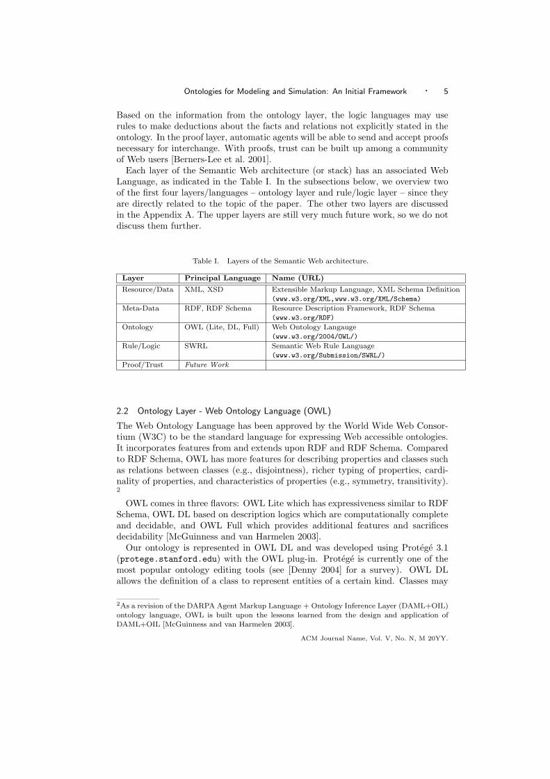
Each layer of the Semantic Web architecture (or stack) has an associated WebLanguage, as indicated in the Table I. In the subsections below, we overview twoof the first four layers/languages – ontology layer and rule/logic layer – since theyare directly related to the topic of the paper. The other two layers are discussedin the Appendix A. The upper layers are still very much future work, so we do notdiscuss them further.
Table I. Layers of the Semantic Web architecture.
Layer Principal Language Name (URL)
Resource/Data XML, XSD Extensible Markup Language, XML Schema Definition(www.w3.org/XML,www.w3.org/XML/Schema)
Meta-Data RDF, RDF Schema Resource Description Framework, RDF Schema(www.w3.org/RDF)
Ontology OWL (Lite, DL, Full) Web Ontology Langauge(www.w3.org/2004/OWL/)
Rule/Logic SWRL Semantic Web Rule Language(www.w3.org/Submission/SWRL/)
Proof/Trust Future Work
2.2 Ontology Layer - Web Ontology Language (OWL)
The Web Ontology Language has been approved by the World Wide Web Consor-tium (W3C) to be the standard language for expressing Web accessible ontologies.It incorporates features from and extends upon RDF and RDF Schema. Comparedto RDF Schema, OWL has more features for describing properties and classes suchas relations between classes (e.g., disjointness), richer typing of properties, cardi-nality of properties, and characteristics of properties (e.g., symmetry, transitivity).2
OWL comes in three flavors: OWL Lite which has expressiveness similar to RDFSchema, OWL DL based on description logics which are computationally completeand decidable, and OWL Full which provides additional features and sacrificesdecidability [McGuinness and van Harmelen 2003].
Our ontology is represented in OWL DL and was developed using Protege 3.1(protege.stanford.edu) with the OWL plug-in. Protege is currently one of themost popular ontology editing tools (see [Denny 2004] for a survey). OWL DLallows the definition of a class to represent entities of a certain kind. Classes may
2As a revision of the DARPA Agent Markup Language + Ontology Inference Layer (DAML+OIL)ontology language, OWL is built upon the lessons learned from the design and application ofDAML+OIL [McGuinness and van Harmelen 2003].
ACM Journal Name, Vol. V, No. N, M 20YY.

6 · John A. Miller et al.
(i) be divided into subclasses (ii) have properties/relationships, and (iii) have in-stances. Properties/relationships may have certain characteristics (e.g., transitive,symmetric, functional, inverse, cardinality). As such it shares much in commonwith Entity-Relationship Modeling and the Unified Modeling Language (UML).Entity-Relationship Modeling is intended for data modeling, UML is intended forsoftware modeling, and OWL is intended for ontology modeling and knowledgerepresentation that is consistent with the Web infrastructure. Compared to UMLClass Diagrams, OWL DL permits the creation of subproperties as well as moreways of restricting properties/relationships.
2.3 Rule/Logic Layer - Semantic Web Rule Language (SWRL)
There are some recent proposals for languages at the Rule/Logic Layer including theSemantic Web Rule Language (SWRL), which extends OWL DL with the ability towrite rules using a subset of RuleML. It also permits Horn logic rules to be added toOWL descriptions. This allows more complex predicates to be created and used formore precise definitions of concepts. It also has built-ins for basic arithmetic (e.g.,x+y) and comparisons (e.g., x < y). Since the rule/logic layer is in its preliminarystages of development, we plan to enhance DeMO using this layer in our futurework. An alternative to SWRL is RuleML which has a longer maturation horizon.
3. TAXONOMIES FOR DISCRETE EVENT MODELING
Models can be classified based on various characteristics: static vs. dynamic, time-varying vs. time invariant, continuous state vs. discrete state, time-driven vs.event-driven, descriptive vs. prescriptive, analytic vs. numeric [Zeigler 1976; Page1994]. Surveying existing taxonomies is a useful way to begin the developmentof an ontology, hence we first give a brief review of existing simulation modelingtaxonomies and then show how the existing discrete-event modeling formalisms canbe grouped together to serve as a backbone taxonomy for DeMO.
3.1 A review of existing taxonomies
Given a system evolving over time, a model of it can be viewed simply as an approx-imation that captures or mimics the essential features of the system. Commonly,models are classified according to how they deal with time (Static vs. Dynamic),state (Discrete vs. Continuous) and randomness (Deterministic vs. Stochastic).
There are two broad types of simulation modeling: continuous simulation anddiscrete-event simulation. The distinction is based on whether the state can changecontinuously (water level in a reservoir) or at discrete points in time (number of cus-tomers in a bank). Continuous changes are often modeled as differential equationsin which both state and time are continuous. Discrete-event simulation models arevery popular for modeling many types of real-world systems such as banks, hospi-tals, transportation systems, and computer networks so we will focus our attentionon them.
Within discrete-event modeling there are multiple ways to construct a taxonomy.The development/use of simulation programming languages led to the creation oftaxonomies for discrete-event simulation. These languages allowed developers to de-fine models using categories identified with a particular view of reality. DevelopersACM Journal Name, Vol. V, No. N, M 20YY.

Ontologies for Modeling and Simulation: An Initial Framework · 7
used the views implicit with the simulation languages when contemplating the sys-tem [Lackner 1962]. Kiviat’s [1969] discussion of simulation programming languageslead to the basic taxonomy for discrete-event simulation which includes the threeworld-views: event-scheduling, activity-scanning and process-interaction. This typeof taxonomy, in a more general context, which includes simulation, database andworkflow modeling, was discussed in [Miller et al. 1997] and a portion of it is dis-cussed below. Most of the diagrammatic simulation modeling techniques implicitlyor explicitly depict entities (e.g., bank customers) flowing through a system. Theclassification/taxonomy below mentions several popular general simulation model-ing techniques partitioned according to their principal world view.
Event-Scheduling (ES). These models focus on the events that can occur ina system. An event instantaneously transforms the state of the system and/orschedules future events. Future events are scheduled by placing them in a futureevent-list. Time is advanced by jumping to the time-stamp of the earliest event(imminent event) on the list and processing that event.
—Event Graphs (EG). In an event graph, nodes (or vertices) represent events, whiledirected edges represent causality [Schruben 1983]. Edges can be annotated withtime delays and conditions.
Activity-Scanning (AS). These models focus on activities and their precon-ditions (triggers). An activity consists of an event-pair (a start event and anend event). Activities are scheduled when their preconditions become true. TheThree-Phase (TP) approach may be considered to be a more efficient variantof Activity-Scanning or a hybrid of Activity-Scanning and Event-Scheduling. Effi-ciency is gained by putting unconditional events on a future-event list as in ES andstill triggering conditional events as in AS.
—Activity Cycle Diagrams (ACD). Activity Cycle Diagrams are graphs with twotypes of nodes (bipartite graphs), activities and wait states, where the arcs con-nect either activities to wait states or wait states to activities [Tocher 1963; Pidd1992]. These diagrams depict the life-cycles of interacting entities flowing througha system.
—Petri Nets (PN). Petri Nets are graphs with two types of nodes (bipartite graphs),transitions and places, where the arcs connect either transitions to places or placesto transitions [Petri 1962; Peterson 1977]. A place is a storage area for tokens(entities), while a transition takes input token(s) to produce output token(s).A transition will fire if there is a (or are enough) tokens at each of its inputplaces. In Timed Petri Nets, transitions have delays associated with them. InColored Petri Nets, tokens can have attributes. Both Activity Cycle Diagramsand Petri Nets models can be used to generate simulations following either theactivity-scanning or process-interaction world views.
Process-Interaction (PI). These models focus on processes and their interac-tion with resources. A process captures the behavior of an entity as it flows throughthe system, step by step.
—Activity Diagrams (AD). Activity diagrams are graphs consisting of a well de-fined set of functional nodes such as start, terminate, delay, engage resource and
ACM Journal Name, Vol. V, No. N, M 20YY.

8 · John A. Miller et al.
release resource [Birtwistle 1979]. The graph shows the flow of entities as well asresources through the system.
—Network Diagrams (ND). Network (or block) diagrams are used by many pop-ular commercial simulation packages (e.g., General Purpose Simulation System(GPSS) [Schriber 1974], Simulation Language for Alternative Modeling (SLAM)[Pritsker 1979] and SIMulation ANalysis (SIMAN) [Pegden et al. 1990]). Thesenetwork diagrams are similar to activity diagrams, but have more types of nodescorresponding to the underlying primitives supported in their associated simula-tion languages.
Besides these three classical world-views, there are other popular approaches: (i)State Transition Models (e.g., Markov models), (ii) Discrete Event System Specifi-cation (DEVS) models [Zeigler 1976; Zeigler et al. 2000] and (iii) Object-OrientatedSimulation (see Appendix D).
Most of the simulation taxonomies are based on execution characteristics ofmodels – scheduling events, scanning for activities, interacting processes. Fish-wick [1995; 1996a] suggests a different approach based on model “syntax.” Inparticular, he creates a taxonomy that conforms closely to the taxonomy of pro-gramming languages: declarative, functional, and constraint. By closely couplingsimulation models with programming paradigms, this taxonomic exposition high-lights the connections between models and programs. For example, declarative fi-nite state automata and Petri nets bear similar features to declarative programminglanguages based on rules and logic. Functional methods of simulation modeling arerelated to functional languages formalized with lambda calculus, such as Lisp.
Another useful way to build a taxonomy is based on subsumption relationshipsbetween the formalisms used (e.g., General Semi-Markov Processes (GSMPs) sub-sume Semi-Markov Processes (SMP), which subsume Markov Chains (MCs)). For-mal structures can also be compared using homomorphisms to show one modelingtechnique can do anything another technique can, or isomorphisms to show twotechniques are equivalent. This is the basic approach used to develop a backbonetaxonomy for the DeMO ontology.
Discrete event simulation models can be defined as abstract, dynamic, descriptive,numerical models [Page 1994]. Cassandras and Lafortune [1999] define discrete-event systems as discrete-state, event-driven, time-invariant, dynamic models. Withinthe class of discrete event models, further subclassification may be achieved by themeans of the following characteristics: stable vs. unstable models, steady-statevs. transient models, deterministic vs. stochastic, and autonomous (no input) vs.nonautonomous models [Page 1994]. Nance [1993] divides simulation models intothree main classes: Monte-Carlo, continuous, and discrete event. The InternationalCouncil on Systems Engineering maintains and updates a broad taxonomy for soft-ware tools including simulation tools [INCOSE 2002]. Schruben and Roeder [2003]propose a new way of organizing the highest levels a modeling taxonomy for discreteevent simulation based on a dichotomy between resident entity cycle modeling andtransient entity flow modeling as opposed to the classical three worldviews. Anontology is more than a taxonomy, and indeed may implicitly capture multipletaxonomies.
In Section 4 we will show and discuss some of the details of the Discrete-eventACM Journal Name, Vol. V, No. N, M 20YY.
Ontologies for Modeling and Simulation: An Initial Framework · 9
Modeling Ontology (DeMO). DeMO is an ontology for discrete-event modeling(system dynamics for discrete-event systems). In their essence, the models in theontology capture how state evolves over time, although they may focus on otherconcepts such as entity, event or place. The state space may be either discrete (finiteor countably infinite) or continuous, while time may be continuous (uncountable),although the number of state changes (via events) must be discrete. We considerboth stochastic models and deterministic models. It is hoped that the DeMO on-tology will be useful to researchers and practitioners of modeling and simulation.Such an ontology could find application in locating modeling and simulation soft-ware, particular modeling applications and modeling components. It also may helpin integrating different aspects of simulation and modeling in a robust and flexibleway, interdisciplinary model exchange, as well as facilitating meta-modeling andmulti-modeling [Fishwick and Zeigler 1992; Vangheluwe et al. 2002].
At present our ontology development has focused on the classical world views.Newer modeling paradigms such as object oriented and agent based while impor-tant are more focused on large scale model development which includes issues ofhierarchical modeling an model reuse. After developing the core ontology it wouldbe natural to pursue these in our future work.
3.2 Grouping Discrete-Event Modeling Formalisms — a Backbone Taxonomy for theOntology
As a first step in the development of the DeMO ontology, we start by composing ataxonomy of discrete-event modeling formalisms. We do this by combining existingformalisms into a backbone taxonomy on which the rest of the ontology is built.This is done so that we can collect the existing knowledge in an organized fashion.Although slight modifications to formalisms were made, our purpose was not tocreate a new unifying framework, but rather to create a useful stepping stone forproducing the ontology. A good review and evaluation of existing formal approachesin the field of discrete-event simulation is given in [Page 1994].
An alternative to creating a taxonomy for several existing formalisms is to create aunified general framework such as DEVS [Zeigler 1976; Zeigler et al. 2000]. ClassicalDEVS is given by a seven tuple that includes three sets (input, output, state)and four functions (time advance, internal transition, external transition, output).It also implicitly includes a set for time. Zeigler shows how to translate event-scheduling and activity-scanning models into classical DEVS. Process interaction isalso formalized with an extended structured model. These well defined formalismscould be used for ontological development (see [Silver et al. 2006] for an examplerelated to process interaction).
We use a series of top formalisms that differ from each other in their structuralprinciples motivated by their world-views and modeling power. The assumptionis that each of the top formalisms is general enough to serve as a formal basis fordiscrete-event systems modeling. Other modeling formalisms are added by plac-ing restrictions on higher formalisms (e.g., timed automata is a stochastic timedautomata with a deterministic clock structure, etc.).
The result is a hierarchical structure where objects are related through is-aor subclass-of (parent/child) relationships. This kind of taxonomy with corre-sponding links on the Web is easily browsed by humans and may serve as a good
ACM Journal Name, Vol. V, No. N, M 20YY.

10 · John A. Miller et al.
reference. However, more complex and meaningful knowledge can be captured inan ontology by using stronger semantic connections in the discrete-event simulationmodels. Links to other Web resources can be established as well.
To help develop the conceptual framework, rather than getting bogged down indetails related to simulation implementations, we will focus on modeling conceptsindependently of simulation/implementation details as well as observation frames.In order to have an appropriate level of precision with these concepts, we haveexamined many of the common modeling formalisms used in simulation.
Since we are initially aiming to create an ontology for discrete-event modelsdecoupled from model simulation and model observation paradigms, we want toconstruct taxonomy based on characteristics of models. We pick structural charac-teristics of the modeling formalisms as the basis for this classification.
Model formalisms are typically defined as n-tuples where the elements of a tupleare usually sets or functions. Given a certain type of model (e.g., Markov Chain,Timed Automata, Event Graph, Timed Petri Net, Activity Cycle Diagram, etc.)these elements are defined and a collection of them (an n-tuple) serves as a formaldefinition of the model. In lieu of having a well accepted formalism, standardterms and definitions [Schriber and Brunner 1996] may also be relied upon. Thisparticularly comes into play with process-oriented models, where there is a greatdeal of literature on terms and definitions, but comparatively little on formalisms[Zeigler 1976; Cota and Sargent 1992; Silver et al. 2006].
In building the taxonomy, we generally use the following strategy: the elementsare identified as independently as possible of any particular type of model and thenby grouping, restricting, and/or specializing these elements, the model types inthe taxonomy are produced. Care must be taken, since if too much generalizationand unification are done, the models lose their individual flavor and possibly theirusefulness.
In modeling and simulation, a model can be thought of as representing a mini-world that has its own structure (what does it look like) and behavior (what doesit do). In order to define a model’s mini-world, its structure and behavior need tobe defined. Sets and functions on these sets can be used to define the structureof the mini-world, while additional explanation is usually provided to define thebehavior. Since the behavior depends on the structure, we consider structure to bemore fundamental. Hence, we use structure for the first-level classification in ourtaxonomy.
In general, most useful dynamic models will have notions of time and space. Inspace and time, things happen to change the mini-world. In continuous models,change may be constantly occurring, while for discrete-event models, measurablechange occurs only at discrete points in time. Dynamic discrete-event models maytherefore be characterized by three primitive sets based on time, space and events.Although time may be abstract, it intuitively matches our notions of actual time.We refer to the corresponding set as the time set (T ). On the other hand, spacemay correspond to our notion of the three-dimensional world or it may be highlyabstract, essentially giving the state (complete current configuration of the mini-world). Thus, we refer to the corresponding set as the state space (S). Changes tothe model’s mini-world are caused by events, which in discrete-event models occurACM Journal Name, Vol. V, No. N, M 20YY.
Ontologies for Modeling and Simulation: An Initial Framework · 11
instantaneously. The types of changes that may occur (i.e., what can happen inthe model’s mini-world) define the event set (E).
Many of the models in this taxonomy will explicitly use these three primitivesets in their definitions, while others will use related sets (e.g., activity, place andentity) from which the primitive sets may be deduced.
Based on their structural characterization (i.e., the sets used to define the modelstructure), we use the following first-level classification.
—Discrete-Event Models - Time.—State-Oriented Models - State and Event.—Activity-Oriented Models - Activity and Place.—Event-Oriented Models - Event and State.—Process-Oriented Models - Process and State
Since a great deal of formal work has already been done for State-Oriented andActivity-Oriented models we first concentrate on these two model types and thencover Event-Oriented and Process-Oriented models more briefly.
3.2.1 State-Oriented Models. In the DeMO ontology, State-Oriented modelsmay be characterized by the three sets, S, E and T .
—State space (S) - A model changes over time from state to state. Its currentstate at a particular time is quantified by the values of a collection of indica-tors. Indicators record various properties of the model. The set of all possiblecombinations of indicators for this model is called the state space S.
—Event set (E) - An event characterizes a type of event instance that may occur.An event instance occurs instantaneously at a particular time and may cause astate change and/or future events. Event e ∈ E is enabled at time t1 and fires attime t2. The difference between these times is referred to as the event lifetime.The combination of the event and its firing time may be viewed as an eventoccurrence (e, t).
—Time set (T ) - A nonnegative number represents the passage of time. Time t ∈ Tis integer-valued (e.g., t ∈ Z+) for discrete-time models and real-valued (e.g.,t ∈ R+) for continuous time models (vector-valued time is also a possibility).
These three fundamental sets establish the type of world that is being modeled.We will consider models in which S is finite (finite state models), as well as, modelsin which S is countably infinite (infinite state models). The size of the set Eindicates the number of distinct types of events that can occur and must always befinite. Finally, the time set, T may be countably infinite (discrete time models) oruncountably infinite (continuous time models).
In addition to these three sets, three functions are needed to define the structureof the model (or drive the model). These driving functions will allow the definitionof many types of State-Oriented models including Generalized Semi-Markov Pro-cesses (GSMP). Other types of Markov models allow for simpler definitions, whichwe will indicate as restrictions on these functions. To provide a more intuitive feelfor these functions, we first define them as deterministic functions, although any orall of them may be stochastic.
ACM Journal Name, Vol. V, No. N, M 20YY.

12 · John A. Miller et al.
—Activation Function - a : S × E → {0, 1}The activation function a is a Boolean function indicating which events a stateenables. Enabling an event creates an instance of that event which is said to beactive until it fires or is cancelled. This function determines what can happen.
—Clock Function - c : S × E → TWhen each event instance is created, a clock timer is set and when it reacheszero, the event fires (or occurs), unless already cancelled. Other functional formsfor clock functions are also possible. We have chosen to make the clock settingdependent on the current state and the type of event. In Haas [2002], the clockfunction may also depend on the prior state as well as the combination of eventscausing the prior transition. This function determines when things happen. Note,in the implementation of simulators, the clocking or scheduling of events is typi-cally accomplished by using a future event list.
—State Transition (or Delta) Function - d : S × E → SThe occurrence of events drives the model to change over time. The elementalchanges from current state si to next state sj are determined by the state transi-tion function, i.e., sj = d(si, e). This function determines where to go in responseto something happening.
Note, these definitions assume a time-homogeneous model where the laws governingthe dynamics do not change over time; otherwise, time would need to be added tothe domain for these functions.
We could introduce additional functions to initialize the model. Alternatively,we could extend the domains of c and d to accept nil arguments, upon which cgives the starting time and d gives the starting state for the model.
The details of several existing formalisms for State-Oriented models are pre-sented in Appendix B. The Tables II and III summarize this discussion. Thesemodels include many popular Markov (e.g. Generalized Semi-Markov Processesand Continuous Time Markov Chains) models as well as classical automata (e.g.Deterministic Finite Automata).
Table II. Sets and functions for State-Oriented models.Symbol Name
S State Space
E Event Set
T Time Set
a Activation Function
c Clock Function
d Transition Function
3.2.2 Activity-Oriented Models. State-Oriented models utilize the concepts ofstate, time and event. Although state can be thought of as a location (where themodel is) it is really an indicator of the model’s configuration. One way to thinkabout it in terms of location is to imagine there is an entity (or token) movingaround in the models. The entity’s current location marks the current state (asone would do when creating an animation of a Markov model). Doing this is a firstACM Journal Name, Vol. V, No. N, M 20YY.

Ontologies for Modeling and Simulation: An Initial Framework · 13
Table III. State-Oriented models.Model Acronym Model Name Citation
GSMP+SE Generalized Semi-Markov Process [Haas and Shedler 1987](w/ Simultaneous Events)
GSMP-SE Generalized Semi-Markov Process [Glynn 1983](wo/ Simultaneous Events)
SMP Semi-Markov Process [Levy 1954; Smith 1955]
CTMC Continuous Time Markov Chain [Kolmogorov 1933]
DTMC Discrete Time Markov Chain [Markov 1913]
STA Stochastic Timed Automata [D’Argenio et al. 1995]
TA Timed Automata [Alur and Dill 1994]
SA State Automata [McCulloch and Pitts 1943]
DFA Deterministic Finite Automata [McCulloch and Pitts 1943]
step to filling state-time with entities and having the events move them around (orcreate or destroy them).
If multiple entities (or tokens) are introduced, the relationship between state,entity and location is no longer so simple. We need locations on all the entitiesand therefore the state must include all this information, e.g., in some type of statevector. One might try recording the locations of all entities currently in the model,however, since the number of entities varies in time, the state vectors would havevarying lengths. To make the vectors have fixed length, a given number of places(or stations) could be specified at which entities (or tokens) reside, until an event(or events) occurs to move them to other places. In this case, the state of modelcan be represented as a vector n
n(t) = (n1(t), ..., nk(t))
where np(t) ∈ Z+0 is the number entities located in place p ∈ P at time t.
For these types of models, it is also convenient to think of a more composite viewof action. For example, service at a station in a Queuing Network may be thoughof as an activity.
Therefore, for activity-based models, our fundamental group of sets will replaceS and E with P and A as defined below to yield (P , A, T ).
—Place Set (P ) - A place is a location within a positional space (e.g., a metric spaceor topological space) indicating where a token is. Place p is a location withinthe model (e.g., logically at a node in a graph or physically in an n-dimensionalcoordinate system).
—Activity Set (A) - An activity can be thought of as atomic behavior and itusually happens over a time interval, which is delimited by a start-event andan end-event. Activities cause entities to move (or using Petri Net terminology,transitions cause tokens to move from place to place).
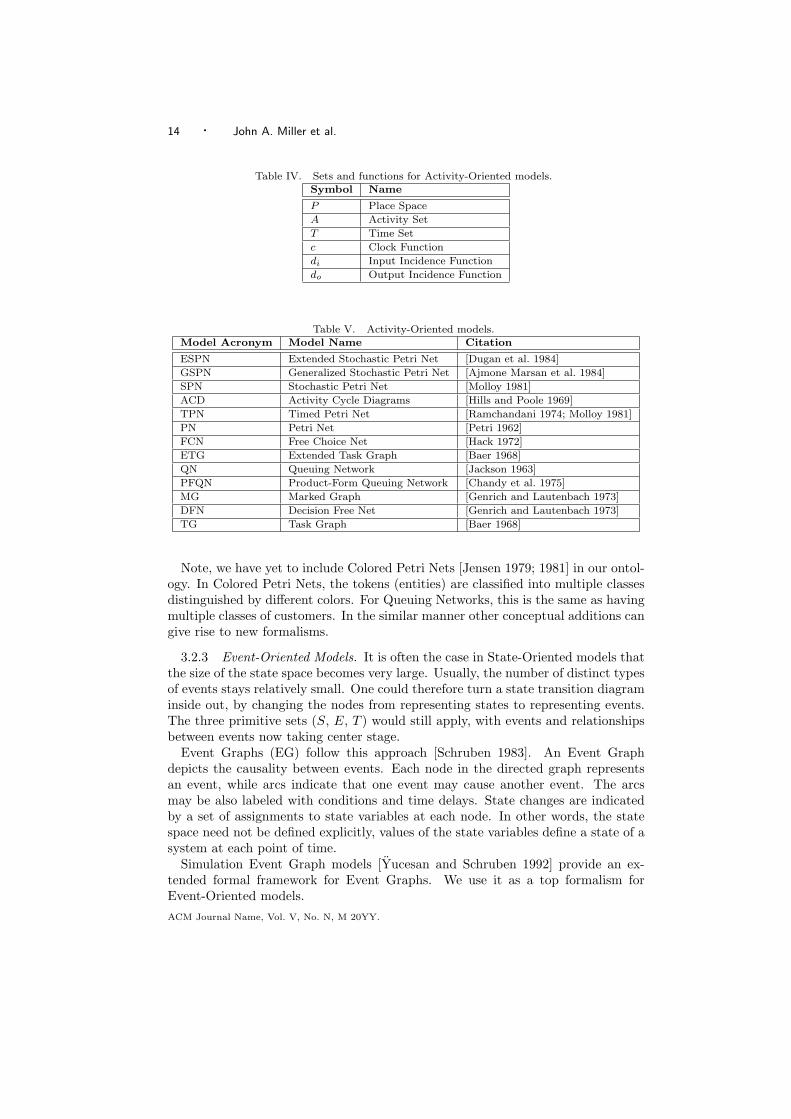
Appendix C presents the details of the formalisms for Activity-Oriented modelsincluding Extended Stochastic Petri Nets as well as Queueing Networks. OtherActivity-Oriented model formalisms in the taxonomy can be derived from it. TheTables IV and V summarize this discussion.
ACM Journal Name, Vol. V, No. N, M 20YY.
14 · John A. Miller et al.
Table IV. Sets and functions for Activity-Oriented models.Symbol Name
P Place Space
A Activity Set
T Time Set
c Clock Function
di Input Incidence Function
do Output Incidence Function
Table V. Activity-Oriented models.Model Acronym Model Name Citation
ESPN Extended Stochastic Petri Net [Dugan et al. 1984]
GSPN Generalized Stochastic Petri Net [Ajmone Marsan et al. 1984]
SPN Stochastic Petri Net [Molloy 1981]
ACD Activity Cycle Diagrams [Hills and Poole 1969]
TPN Timed Petri Net [Ramchandani 1974; Molloy 1981]
PN Petri Net [Petri 1962]
FCN Free Choice Net [Hack 1972]
ETG Extended Task Graph [Baer 1968]
QN Queuing Network [Jackson 1963]
PFQN Product-Form Queuing Network [Chandy et al. 1975]
MG Marked Graph [Genrich and Lautenbach 1973]
DFN Decision Free Net [Genrich and Lautenbach 1973]
TG Task Graph [Baer 1968]
Note, we have yet to include Colored Petri Nets [Jensen 1979; 1981] in our ontol-ogy. In Colored Petri Nets, the tokens (entities) are classified into multiple classesdistinguished by different colors. For Queuing Networks, this is the same as havingmultiple classes of customers. In the similar manner other conceptual additions cangive rise to new formalisms.
3.2.3 Event-Oriented Models. It is often the case in State-Oriented models thatthe size of the state space becomes very large. Usually, the number of distinct typesof events stays relatively small. One could therefore turn a state transition diagraminside out, by changing the nodes from representing states to representing events.The three primitive sets (S, E, T ) would still apply, with events and relationshipsbetween events now taking center stage.
Event Graphs (EG) follow this approach [Schruben 1983]. An Event Graphdepicts the causality between events. Each node in the directed graph representsan event, while arcs indicate that one event may cause another event. The arcsmay be also labeled with conditions and time delays. State changes are indicatedby a set of assignments to state variables at each node. In other words, the statespace need not be defined explicitly, values of the state variables define a state of asystem at each point of time.
Simulation Event Graph models [Yucesan and Schruben 1992] provide an ex-tended formal framework for Event Graphs. We use it as a top formalism forEvent-Oriented models.ACM Journal Name, Vol. V, No. N, M 20YY.

Ontologies for Modeling and Simulation: An Initial Framework · 15
The set of events (event types) is explicitly specified. This event set E is identicalin meaning to an event set in State-Oriented models. In Simulation Event Graphs,events correspond to nodes (vertices).
Instead of explicitly specifying the state space S of the system, however, statevariables are defined in Event-Oriented models. Each event has a set of state vari-able changes associated with it. Together with initialization of the state variables,this allows one to obtain the state of the system (as a combination of state variablevalues) at any point during the simulation of the model, but not to specify the statespace explicitly before running the model.
Sets of scheduling edges and canceling edges relate events to each other: if anevent e1 is connected to an event e2 with a scheduling/canceling edge, that meansthat the occurrence of event e1 prompts scheduling/canceling of event e2.
Our notion of clock function from the previous section corresponds to Yucesanand Schruben’s set of edge delay times, e.g., if occurrence of event A schedules anevent B, then the edge connecting A and B may have time delay τ associated withit (i.e., B is scheduled to occur τ units from occurrence of event A).
A transition function (how does the state change) can also be defined in a similarmanner, in order to determine how the next state is computed from the currentstate and current event.
Following the notation of Yucesan and Schruben’s, a set of edge conditions needsto be specified. This roughly corresponds to the activation function of a previoussection. The current event along with the current state, determine the next event.
In order to allow for tie breaking of the simultaneously occurring events the setof event priorities should be specified as well. It can be defined as a priority rankingfunction.
In the event-scheduling interpretation, the mechanics of the model will work thefollowing way. At the initialization event all the state variables are initialized.Then all the scheduling edges coming out of the initialization event are examined,their conditions checked and if they hold the corresponding events are scheduledaccording to the time delays and priority ranking function. The first event on theresulting event list then occurs. The process is now repeated with canceling edgesalso considered.
It is interesting to note that Simulation Graph Models can be transformed fromevent scheduling world view to activity scanning world view and vice versa [Schrubenand Yucesan 1989]. This sort of duality is important to keep in mind when con-structing an ontology.
Table VI. Event-Oriented models.Model Acronym Model Name Citation
EG Event Graph [Schruben 1983]
SGM Simulation Graph Models [Yucesan and Schruben 1992]
3.2.4 Process-Oriented Models. The process interaction world view is richer andmore widely varied than the other world views. Consequently, developing a conciseand adequate formalism is quite a challenge.
ACM Journal Name, Vol. V, No. N, M 20YY.

16 · John A. Miller et al.
There has been less work on formal definitions for the process interaction worldview than for the other world views. Zeigler [1976] describes a structured modelfor process interaction using elements of the DEVS formalism. Cota and Sargent[1992] modify the process interaction world view to support full encapsulation,while still allowing preemption of one process by another process. Schriber andBrunner [1996] provide terminology for the process interaction world view wherethey discuss the transaction flow approach to process interaction simulation. Theydescribe processes as transactions that are discrete units of traffic moving frompoint-to-point in a system, while competing with each other for scarce resources.Silver and others [2006] review the work of Zeigler, Cota and Sargent, and Schriberand Brunner as a basis for developing a process interaction ontology to be used inontology based representations of Process-Oriented models.
Following these ideas for the transaction flow approach to process-interactionworld-view, simulation models that conform to this world-view may be describedas having two types of components - active (processes) and passive (resources).Processes take actions which can change the state of the system, while resourcesare unable to directly take actions. A process can be thought of as being madeup of a set of descriptive variables, a time left in the current state, and a setof computation segments. Each of a process’ computation segments consists of acondition C under which the segment will be activated, an activation function fthat determines the actions to be taken when the segment is activated, and a labell which points to the first statement of the segment.
When a simulation begins, activation notices are placed onto a list known as aFuture Activations List (FAL). Each notice contains a process, the reactivation timeof the process, and label value representing the reactivation point of the process.The FAL is ordered by reactivation time. It is then processed in sequential orderby removing the first activation notice which contains the current process. Thesimulation clock is set to the current process’ reactivation time and execution ofthe process begins at the computation segment specified by the reactivation point.If the condition C associated with the segment evaluates to true, the segment’sactivation function f is applied. Among other things f may change the state of thesystem and schedule activation notices for the process or its influencees.
Components within the process-interaction simulation interact with one anotheras influencers and influencees. Influencers (components which influence other com-ponents) and influences (components that are influenced by other components) canbe represented using a graph where the nodes are components of the model andthe edges indicate which components influence other components. The state of in-fluencers may be used in the computations of influencees’ conditions and activationfunctions. Influencers’ functions may also change the state of influencees. A moredetailed treatment of process-interaction simulation is covered in [Silver et al. 2006].
Overall, there are two common approaches to process interaction simulation: thetransaction flow approach and the active server approach, with the former beingmore popular [Henrikson 1981; Carson 1993]. With the transaction flow approachthe focus of the model is on the actions taken by active processes (transactions orentities) on the systems passive resources (e.g., servers) [Cota and Sargent 1992].Entities are viewed as executing simulation logic as they pass through the systemACM Journal Name, Vol. V, No. N, M 20YY.

Ontologies for Modeling and Simulation: An Initial Framework · 17
Fig. 1. Portion of the DeMO’s backbone taxonomy.
which may be represented as a block diagram or a directed graph. The entities(processes) in this approach may be implemented using threads or coroutines. Theactive server approach differs from the transaction flow approach in that it focuseson the actions taken by the system’s resources. In this approach the entities areseen as passive and the resources are seen as active. In the active server approach,resources may be implemented using threads or coroutines that wait for the arrivalof entities and then execute logic to provide service for those entities [Pasquini andRego 1998].
Currently, DeMO includes a subset of the ontology in [Silver et al. 2006]. Thispart of DeMO, however, needs to be expanded and better integrated with the restof DeMO. Because of the complexity of the process-interaction world-view, this isno easy task.
4. DEMO ONTOLOGY
The previous section discussed a backbone taxonomy (see Figure 1) for discrete-event models to serve as a foundation for the development of the Discrete-eventModeling Ontology (DeMO). The choice of the structure of the taxonomy, as wellas the particular details of the model hierarchy may be open to debate and/or mod-ifications. In our opinion, the resulting backbone taxonomy must be a compromise
ACM Journal Name, Vol. V, No. N, M 20YY.

18 · John A. Miller et al.
between understandability, elegance, current practice and uniformity.As mentioned before, an ontology is more than a single taxonomy – it should
contain formal specifications of all concepts related to the knowledge domain inconsideration and the relationships between these concepts. It may indeed implic-itly capture multiple taxonomies. In fact, it is not absolutely necessary to have abackbone taxonomy in order to build an ontology. However, having a well-definedtaxonomy makes it easier to “grow” the ontology, to categorize the underlying con-cepts, and to recognize the existing relationships. In this section, we will put allthe pieces of the discrete-event modeling knowledge domain together and indicatehow they are mapped into the constructs provided by the Web Ontology Language(OWL).
It must be noted that we do not claim to have all possible discrete-event mod-eling techniques included in the DeMO ontology or to capture all the nuances ofthe modeling formalisms. Nor do we claim that the approach used in building thisontology is in some way the best. DeMO was designed as an OWL-based proto-type ontology whose purpose was to demonstrate the feasibility of this approachin general, as well as, to bring to the forefront potential benefits and pitfalls ofthe methods and principles used in its construction. Some of the decisions madein the process of building DeMO were not rigorously justified, but rather based onauthors’ intuition and sometimes directed by the limitations of the tools currentlyavailable. Further developments and research are anticipated before any finalizedversion of the modeling ontology will take shape. The eventual choice should bemade by consensus, as has been done in other fields that have developed ontologies.
4.1 How Much Knowledge Should DeMO Have?
When building DeMO, we are not focused on supporting any one particular appli-cation or usage (though some of the possible applications are discussed in Section5), rather it aims to be “generally useful”. It may seem, therefore, that our maingoal at the moment is to capture as much knowledge about discrete-event modelingdomain as possible, i.e., provide machine-processable formal specifications for allrelated concepts and their relationships (at least within the scope defined by ourbackbone taxonomy). This, of course, may prove to be a neverending task, sincemost concepts are based on other concepts, which, in turn, may be defined in termsof yet other concepts, and so on. The process may, in principle, go on foreverand thus a decision about cut-off points of conceptualization has to be made. Thecut-off points (in general, application specific) may serve as a set of axioms or baseconcepts on which the ontology is developed. Since we did not want to committo any particular application, our choices of base concepts were mostly dictatedby common sense and convenience (a compromise between the desire to include asmany details as possible and the increasing complexity of the expanding conceptspace).
To create any ontology with a high level of precision does require the definition ofmany base concepts. It is often the case, however, that some of these concepts comefrom different fields and it is better to have them formalized by experts in thesefields. The DeMO ontology, for example, may need some fundamental mathematicalconcepts to be included. One way to do this is to link the ontology to anotheralready developed ontology (sometimes called the upper ontology) such as SUMOACM Journal Name, Vol. V, No. N, M 20YY.
Ontologies for Modeling and Simulation: An Initial Framework · 19
ModelConcept
DeModel
ModelComponent ModelMechanism
has-Components has-Mechanisms
uses uses
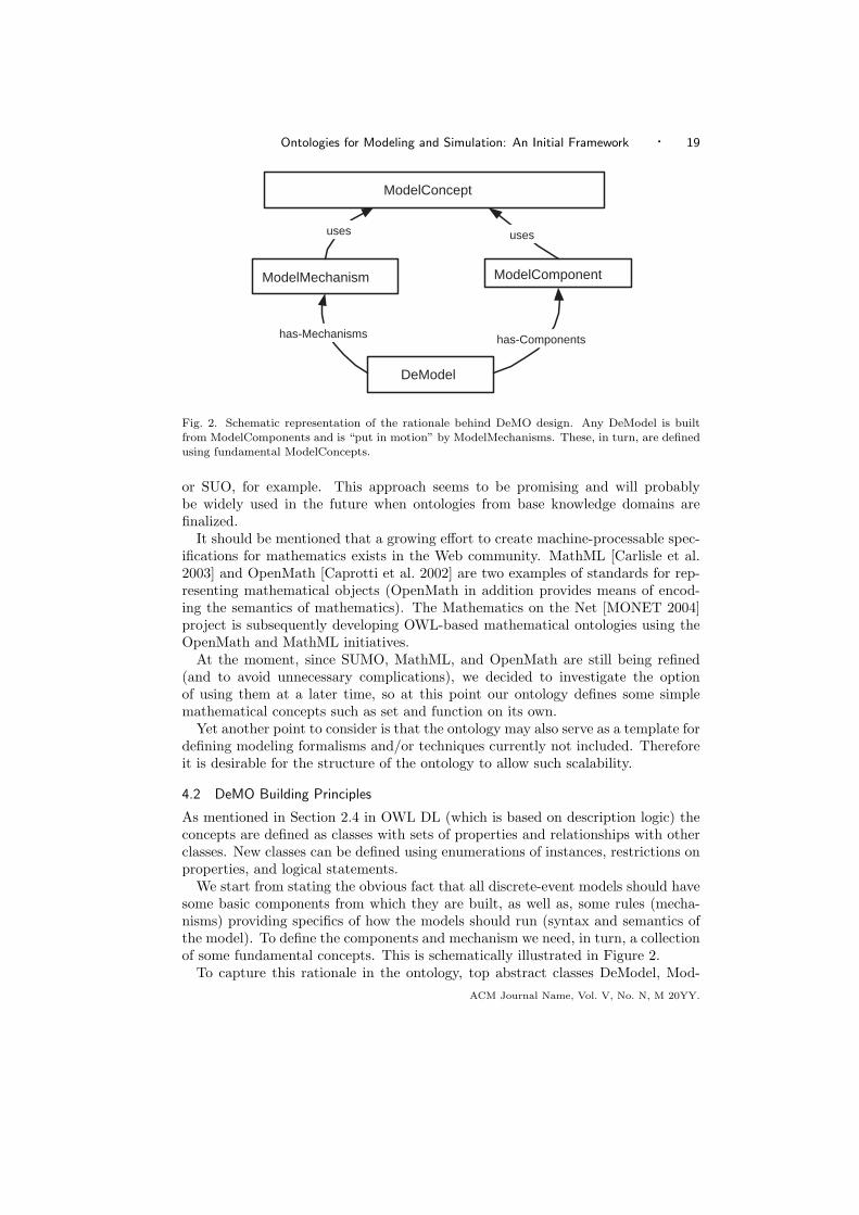
Fig. 2. Schematic representation of the rationale behind DeMO design. Any DeModel is builtfrom ModelComponents and is “put in motion” by ModelMechanisms. These, in turn, are definedusing fundamental ModelConcepts.
or SUO, for example. This approach seems to be promising and will probablybe widely used in the future when ontologies from base knowledge domains arefinalized.
It should be mentioned that a growing effort to create machine-processable spec-ifications for mathematics exists in the Web community. MathML [Carlisle et al.2003] and OpenMath [Caprotti et al. 2002] are two examples of standards for rep-resenting mathematical objects (OpenMath in addition provides means of encod-ing the semantics of mathematics). The Mathematics on the Net [MONET 2004]project is subsequently developing OWL-based mathematical ontologies using theOpenMath and MathML initiatives.
At the moment, since SUMO, MathML, and OpenMath are still being refined(and to avoid unnecessary complications), we decided to investigate the optionof using them at a later time, so at this point our ontology defines some simplemathematical concepts such as set and function on its own.
Yet another point to consider is that the ontology may also serve as a template fordefining modeling formalisms and/or techniques currently not included. Thereforeit is desirable for the structure of the ontology to allow such scalability.
4.2 DeMO Building Principles
As mentioned in Section 2.4 in OWL DL (which is based on description logic) theconcepts are defined as classes with sets of properties and relationships with otherclasses. New classes can be defined using enumerations of instances, restrictions onproperties, and logical statements.
We start from stating the obvious fact that all discrete-event models should havesome basic components from which they are built, as well as, some rules (mecha-nisms) providing specifics of how the models should run (syntax and semantics ofthe model). To define the components and mechanism we need, in turn, a collectionof some fundamental concepts. This is schematically illustrated in Figure 2.
To capture this rationale in the ontology, top abstract classes DeModel, Mod-ACM Journal Name, Vol. V, No. N, M 20YY.

20 · John A. Miller et al.
elComponent, ModelMechanism, and ModelConcepts are created. The subclassesof the class DeModel correspond to modeling techniques defined in our backbonetaxonomy, such as Markov Chains, Queuing Networks, Petri Nets, etc. The sub-classes of the class ModelComponent define the building blocks of the model. In ourapproach, they roughly correspond to the elements of the n-tuples used in formaldefinitions of the models. The subclasses of the class ModelMechanism define howthe components operate within the model. The class ModelConcept has subclassesrepresenting the most fundamental concepts pertaining to this knowledge domain.
In other words, in order to define the DeModel subclass within the ontologyone should define the appropriate subclasses of ModelComponent, place them inthe DeModel (i.e., relate the DeModel class with these components), define theappropriate subclasses of the ModelMechanism explaining how these componentswork, and relate the component classes to mechanisms. In our view, this approachwill “keep the door open” for other upper-level formalisms not yet included inDeMO.
The distinction between ModelComponents and ModelMechanisms seems to bea bit arbitrary - some models may be reformulated in such a way that a mechanismcan become a component and vice versa. However, it also seems that separatingthese two concepts provides for greater flexibility and usability of the model speci-fications. (More generally, this situation can be interpreted as defining a borderlinebetween the syntax and the semantics of the model. Having such an explicit bor-derline and being able to move it by redefining model formalisms may be very usefulwhen reasoning about the ontology).
Note that the subclasses of ModelComponent (as well as ModelMechanism) maythemselves form hierarchies and even be organized in taxonomies. These hierar-chies are inherited by the DeModel subclasses and give rise to natural taxonomies(hierarchies) within DeModel class different from our backbone taxonomy. We saythat these hierarchies are implicitly defined for the ontology. One may argue thatultimately a good ontology should seamlessly capture all (or most) of the naturallyexisting hierarchies within itself (something fundamentally different from a taxon-omy). That may include parts of the backbone taxonomy as well (even though wedefine it explicitly by enforcing a-subclass-of relations, it should still “emerge”as a natural hierarchy).
4.3 Defining the Base Terminology
ModelComponents and ModelMechanisms should be formally defined in terms ofthe subclasses of the abstract class ModelConcept which are the basic concepts ofthe DeMO ontology (such as state, event, time, etc.). This means that the sub-classes of ModelConcept are not defined in terms of other concepts (some basicconcepts may be defined it terms of each other though) and represent the cut-offin our categorization. If none of these fundamental concepts reflect the relationsto other non-basic classes in their definitions, then we can achieve a greater flexi-bility by placing ModelConcept in a separate ontology (a glossary of basic terms,if you like). This modular approach may prove useful if several different ontologiesoperating with the same glossary are considered.
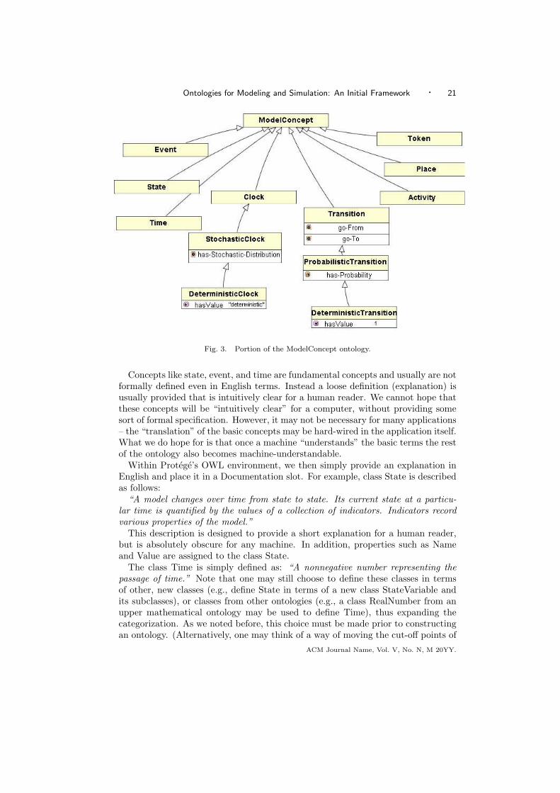
The subclasses of the ModelConcept are State, Event, Time, Transition, Activity,Place, Token, Entity, Process, Resource, Color and Clock (see Figure 3).ACM Journal Name, Vol. V, No. N, M 20YY.
Ontologies for Modeling and Simulation: An Initial Framework · 21
Fig. 3. Portion of the ModelConcept ontology.
Concepts like state, event, and time are fundamental concepts and usually are notformally defined even in English terms. Instead a loose definition (explanation) isusually provided that is intuitively clear for a human reader. We cannot hope thatthese concepts will be “intuitively clear” for a computer, without providing somesort of formal specification. However, it may not be necessary for many applications– the “translation” of the basic concepts may be hard-wired in the application itself.What we do hope for is that once a machine “understands” the basic terms the restof the ontology also becomes machine-understandable.
Within Protege’s OWL environment, we then simply provide an explanation inEnglish and place it in a Documentation slot. For example, class State is describedas follows:
“A model changes over time from state to state. Its current state at a particu-lar time is quantified by the values of a collection of indicators. Indicators recordvarious properties of the model.”
This description is designed to provide a short explanation for a human reader,but is absolutely obscure for any machine. In addition, properties such as Nameand Value are assigned to the class State.
The class Time is simply defined as: “A nonnegative number representing thepassage of time.” Note that one may still choose to define these classes in termsof other, new classes (e.g., define State in terms of a new class StateVariable andits subclasses), or classes from other ontologies (e.g., a class RealNumber from anupper mathematical ontology may be used to define Time), thus expanding thecategorization. As we noted before, this choice must be made prior to constructingan ontology. (Alternatively, one may think of a way of moving the cut-off points of
ACM Journal Name, Vol. V, No. N, M 20YY.

22 · John A. Miller et al.
the ontology, based on some control parameters. This will create a kind of multi-leveled ontology, where level 1, for example, has the class State as a basic concept,and level 2 has subclasses of StateVariable class as basic concepts.)
Some of the basic concepts are related to each other and that can be used toeffectively “define” one concept in terms of the others. For example, we may asso-ciate time with the occurrence of events. Thus the class Event will have a propertycanOccurAt-instance-of-class-Time.3 In other words we “define”, though incom-pletely, the class Event as the class having the aforementioned property.
Yet another possibility is to “define” the basic concepts in terms of their re-lations to other existing concepts, not in the ModelConcept class. Consider, forexample, the class Transition representing “a state change that is caused by oneor more events”. We have a pair of ModelMechanisms in DeMO that are associ-ated with the class Transition. A transition can be enabled using some instanceof a TransitionEnabling mechanism. It can also be triggered using an instance ofTransitionTriggering mechanism. There are a couple of ways to implement theserelationships. One is to assign a property to each of the two ModelMechanisms re-lating them to the class Transition. Say, isAppliedTo-instance-of-class-Transition.Another is to assign two properties to the class Transition: isEnabledBy and isTrig-geredBy. In the latter case, the class Transition is effectively defined as a class withthese two properties related to the two ModelMechanisms (i.e., in this case thetwo ModelMechanisms are, in fact, playing the role of the basic concepts). As inthe case of backbone taxonomy before, we can see that the “quality” assigned to acertain concept may becomes ephemeral with a slight difference in approaches.
It is hard to decide in general which approach is better in the case above. Onone hand, once we define a Transition in terms of ModelMechanisms it ceases tobe a basic concept (understood as being independent of concepts other than thebasic concepts). Then, placing a ModelConcept in a separate ontology makes nosense, since it is now “dependent” on another ontology, and we lose the structuralmodularity offered by the ontology separation. On the other hand the links fromModelConcepts to ModelMechanisms and/or other classes may turn out to be ben-eficial, allowing, for example, for more efficient inference of information. As usual,the answer probably depends on the application.
4.4 Adding the Backbone Taxonomy
Once we decided on the ontology building principles and defined the basic conceptsand the model components, we can recreate our backbone taxonomy of discrete-event modeling techniques. As stipulated in Section 4.2 the abstract class Discre-teEventModel (called here DeModel for short) splits into four first-level subclasses:
—State-Oriented Model,—Event-Oriented Model,—Activity-Oriented Model,
3Following Protege conventions for OWL we capitalize the first and remaining words in class nameswhile keeping the first word in small letters for properties and italicizing it. A property togetherwith its range is denoted using the words instance-of-class-SomeClassName e.g. canOccurAt-instance-of-class-Time. Class instances are denoted using typewriter font style with all wordscapitalized.
ACM Journal Name, Vol. V, No. N, M 20YY.

Ontologies for Modeling and Simulation: An Initial Framework · 23
—Process-Oriented Model.
This is a first-level classification. Each of these classes defines a top formalismfor the underlying subclasses in accordance with specifications discussed in Section3 and Appendices B and C. One way to implement it in OWL is to define thesubclasses of ModelComponent and ModelMechanism: State-OrientedComponent,State-OrientedMechanism, Event-OrientedComponents, etc. Then, obviously, anystate-oriented modeling technique (any subclass of State-OrientedModel) is de-fined by putting restrictions on the properties defined by subclasses of State-OrientedComponent and State-OrientedMechanism.
Let us look closer at the State-Oriented Models. The top abstract class (abstractclass has no instances) has the following properties4:
Property Name Property Range (Instance of)
has-StateSpace DiscreteStateSpace
has-EventSet FiniteEventSet
has-TimeSet TimeSet
has-ActivationFunction ActivationFunction
has-ClockFunction ClockFunction
has-InitialState InitialState
Note that while the StateSpace and the EventSet are presented by their restrictedsubclasses DiscreteEventSpace and FiniteEventSet, respectively, none of the func-tions is restricted. The rest of the State-Oriented Models are rooted in this class.
For the State-OrientedModel the top subclass is a Generalized Semi-Markov Pro-cess (GSMP) model; for the Event-OrientedModel the top subclass is SimulationEvent Graph (SGM); and for Activity-OrientedModel this is Extended StochasticPetri-Net (ESPN).
Consider, for example, the Generalized Semi-Markov Process (see Appendix B),the highest concrete class in the State-Oriented model formalism (Figure 4). It isdefined by placing the following restrictions on the properties presented above:
ClockFunction is restricted to StochasticClockFunctionTransitionFunction is restricted to ProbabilisticTransitionFunction
In addition it uses the following instances of subclasses of ModelMechanism:
Mechanism Name Value
TransitionTriggering MultipleEventTriggering mechanism
TransitionEnabling EventEnabling mechanism
EventScheduling StateMachineScheduling mechanism.
Here the MultipleEventTriggering mechanism is an instance of the Transition-Triggering mechanism, which allows simultaneous event occurrence to trigger atransition, the EventEnabling mechanism means that the transitions are enabledtogether with events, and the StateMachineScheduling mechanism determines theset of imminent events.
The restriction on the TransitionTriggering mechanism is the only difference be-tween GSMP and GSMP-SE. In Protege’s OWL, this is specified merely by over-riding this particular restriction:
4All has- properties are defined as subproperties of a more general has-a property.
ACM Journal Name, Vol. V, No. N, M 20YY.

24 · John A. Miller et al.
has-TransitionFunction
EventSchedulingMechanism
_StateMachineScheduling
Instance-of
Events-Scheduled-by
StochasticClockFunction
TransitionTriggeringMechanism
ProbabilisticTransitionFunction
has-ClockFunction
ClockFunction
is-a
TransitionFunction
is-a
Transitions-Triggered-by
_MultipleEventTriggering
Instance-of
TransitionEnablingMechanism
_EventEnabling
Instance-of
Transitions-Enabled-by
ModelMechanism
is-a is-a
Is-a
Generalized Semi- Markov Process
Fig. 4. Graphical Representation of GSMP Portion of the DeMO Ontology.
TransitionTriggering has value SingleEventTriggering mechanism,
where SingleEventTriggering mechanism is defined to allow only the single eventoccurrence to trigger the transition.
All other properties are inherited from GSMP and need not be redefined. Theclass StochasticTimedAutomata is defined exactly the same way and constitutes aACM Journal Name, Vol. V, No. N, M 20YY.

Ontologies for Modeling and Simulation: An Initial Framework · 25
class synonym of GSMP-SE.It is easy to see how other state-oriented models can be defined in the same
manner. StateAutomata is defined by restricting the ClockFunction to be No-Clock, and TransitionFunction to DeterministicTransitionFunction. Determinis-ticFiniteAutomata is defined by additionally restricting the property has-StateSpaceto be an instance of FiniteStateSpace.
An interesting phenomenon takes place in case of SemiMarkovProcess. Thisclass can be produced from GSMP by changing the method of scheduling events.In DeMO, that may correspond to forcing the EventScheduling mechanism to havean appropriate instance, say the MarkovianSheduling mechanism. On the otherhand, effectively the same model will be produced by putting restrictions on thecardinality of the EventSet, namely, setting it equal to one. (This ambiguity inderivation may not be desirable, but may also turn out to be unavoidable. Thisissue will be addressed with more attention in our future work.)
When considering Activity-Oriented models in general and Petri Nets in partic-ular, we need to define the properties that restrict the topologies of the underlyingPlace-Transition nets. Indeed a number of different classes of Petri Nets are de-fined by merely placing topological restrictions on the P-T nets. These types ofrestrictions are hard to define using OWL and currently (just as the subclassesof ModelMechanism) the topological restrictions are defined using English descrip-tions.
The resulting taxonomy of P-T nets can then be superimposed with other prop-erties of Activity-Oriented models, such as related to ClockFunction, for example.A number of new classes can be defined that way. This raises an interesting ques-tion: what do we do with modeling techniques that can be easily derived from thehigher formalism, but have no common name in the scientific literature? Do weinclude them in the ontology using some automatically generated names or do welump them together under the common general name? How do we differentiateFree-Choice Nets with stochastic timed transitions from the Free-Choice Nets withimmediate transitions? A related question is – what is the best way to deal with thenames of modeling formalisms that are used interchangeably in the literature? Listall the synonyms, or enforce a single standard? Ideally, we feel that the answers tothese questions should be sought by consensus.
4.5 Model Morphisms
Many formalisms can be mapped onto other formalisms, by some sort of transfor-mations. These transformations will take a model instance of one formalism to aninstance of another and can be defined in ontology as well. This can be done usingSWRL rules, for example, that will take model components and mechanisms of oneformalism and morph them in components and mechanisms of another. In somecases such morphisms are easily achieved, in some it may be nearly impossible,but it is most likely that there will be always at least an indirect “path” from oneformalism to another, through a series of such transformations. In other words, thetransformation graph (vertices – formalisms, edges – transformations) will mostlikely have one connected component.
Each such morphism can be defined as an ontological class and represent a prop-erty of a DeModel: formalism A maps to formalism B using morphism M. In fact,
ACM Journal Name, Vol. V, No. N, M 20YY.

26 · John A. Miller et al.
a formalism A may have several different morphisms to a formalism B.Model mapping can be approached from different directions. One approach is
to find some common formalism, that most other formalisms easily map to anduse it as a “mapping hub”. For example, Vangheluwe, proposes DEVS as a com-mon target for many formalism transformations [Vangheluwe 2000]. On the otherhand it may be more efficient to find direct mappings between different pairs offormalism whenever possible and use series of transformations between “distant”formalisms. (See also Caplat and Sourrouille [2002] on model mapping in modeldriven architecture.) Whatever the case, there is no reason why all of these shouldnot be eventually incorporated in the ontology.
Currently, morphisms are not included in DeMO, but the plans exist to do so,for they are envisioned to play key roles in some of the usages of the ontology.
4.6 Observable Models
A model is run to produce results. The results, typically, come from the outputproduced. The output could be very simple or quite complex. For example, fora DFA, an output of 1 means accept, while 0 means reject, thereby, allowing oneto check if a string is in a language. At the other end of the spectrum, a GSMPmay produce a set of sample paths that require statistical analysis to have anymeaningful results.
We have not defined the output for the models so far, since we view the modelas exhibiting behavior and then one may observe it in different ways to producedistinct kinds of output (e.g., DFA may give rise to both Moore machines in whichoutputs depend only on state information [Moore 1956] or Mealy machines in whichoutputs depend on both states and inputs [Mealy 1955]).
When talking about ontological description, it may be beneficial to decouple themodel dynamics (what is really happening as the model executes over time) fromhow it is observed [Miller and Baramidze 2005]. This way the same model canbe “observed” in many different ways. In the ontology it can be represented by“attaching” different output functions to the modeling formalism, allowing one tocapture more knowledge with a smaller ontology.
A “perfect” output function gives the observer a direct access to all dynamic vari-ables of the model. In general, however, the observation window may be restrictedto only certain aspects of a modeled system. This may be represented by an outputfunction that takes the “perfect” output to a more restricted form. This functionmay have stochastic behavior as well. In the case of Hidden Markov Models, forexample, we can imagine a regular Markov Chain formalism with a stochastic out-put function that probabilistically maps a current state of the system to one of theoutput symbols.
The DeMO ontology concentrates only on model specifications. Currently, outputfunction and related concepts are not represented in DeMO, and generally mayconstitute an extended ontology of their own, that, when combined with DeMO,will give rise to an Observable Model paradigm.
Similarly, the model can be decoupled from how it is simulated. Different sim-ulators may have vastly different implementation approaches for identical models.Just as with output functions, one can imagine “attaching” different simulators toobservable model formalisms.ACM Journal Name, Vol. V, No. N, M 20YY.
Ontologies for Modeling and Simulation: An Initial Framework · 27
5. PUTTING THE DEMO ONTOLOGY INTO PRACTICE
An ontology for discrete-event modeling and simulation, such as DeMO, ultimatelyshould be judged by the benefits it brings. Generally, an ontology may be looked atas a knowledge repository about a specific domain. The ontology for discrete-eventmodeling should therefore specify the concepts used in this domain and relationsbetween them. It must be emphasized that such an ontology should not be consid-ered as some sort of unifying superformalism for discrete-event models. Instead, itis a collection of explicit knowledge concepts about different existing formalisms.Any discrete-event modeling formalism may, in principle, be “inserted” in thisrepository and the relations to other formalisms and the underlying concepts maybe represented as well. Placing the ontology on the Web makes it a centralized,machine-readable knowledge repository that can be accessed and used by eithermodelers or computer applications in many different ways. The presence of thisexplicit knowledge on the Web organized in such a fashion is a useful step in theevolution of Web-based modeling and simulation. The ontology itself will grow andevolve through combined efforts of the entire modeling community. As a result,new, maybe unexpected, uses of and directions for DeMO ontology developmentwould emerge in time, driven by the needs of modelers and the demands of differentapplication domains.
5.1 Ontology Driven Modeling
One of the potentially useful applications of DeMO is ontology driven model con-struction and simulation modeling. Consider the entire process of model develop-ment. Usually a modeler is presented with a real-world problem and has to come upwith a model of a relevant system, which will imitate the system and facilitate thesolution of the original problem. This means that the model should allow the useof some readily available tools that can help to analyze or solve the original real-world problem. These tools may be simulators, analyzers, solvers, mathematicalformulas, etc. Thus the modeler’s task is to take the real-world problem, abstractand translate it to some formal model (explicitly or implicitly), and then find andapply relevant tool(s) to this model.
With this model-centric view in mind consider placing a modeling ontology (e.g.,DeMO) in the middle of this paradigm. We believe that this may greatly helpmapping from the application domain (real-world problem) to the modeling andsimulation domain and provide robustness and flexibility to the modeler.
5.1.1 Problem −→ Model. Let us restrict ourselves to discrete-event systemsmodeling. DeMO may serve as a middleman between the modeler/researcher andthe simulation and analysis tool. The knowledge expert in some particular fieldmay construct a logical model of the relevant system. The user can then map thislogical model to one or several formalisms in DeMO ontology (e.g. Stochastic PetriNets, or Markov Chains). Intermediate tools can be developed to facilitate thisstep.
In addition, we can argue that the modeler essentially “maps” her conceptualmodel on the portion of the ontology. Indeed, assuming that relationships betweendifferent formalisms are either explicitly represented in the ontology or discovered bysome inference engine, it is sufficient to map the conceptual model on only one of the
ACM Journal Name, Vol. V, No. N, M 20YY.

28 · John A. Miller et al.
formalisms and it will be automatically “remapped” to others. This is a sort of “top-down” approach. Alternatively, one can consider matching parts of the conceptualmodel with model components (building blocks of different modeling formalisms)present in the ontology, and then looking for the formalisms that contain thesecomponents – a “bottom-up” approach.
Traditional modeling approaches. One of the first and necessary steps in modelconstruction is the development of a conceptual model of the system in question.
For example, assume that the modeler already has a conceptual model of somesort in her head. It may be a clear and concise understanding of different entitiesinteracting within the system, or an explicit picture of a finite set of states that thesystem can go through, or the sorts of activities that can happen in the system andunder what circumstances. This itself can be represented diagrammatically, e.g.,a sketch of activities for a supply chain management, or a graph representation ofthe protein-protein interaction network, etc.
The next step is to translate this conceptual model into some formal modeldescription. Usually the modeler has to choose the modeling formalism (or, atleast, a class of formalisms) beforehand, and use an applicable model design toolfor this particular formalism. With DeMO in the middle, this step may instead turnin the process of matching the conceptual model with one or more of the modelingformalisms in DeMO.
Suppose now that the modeler is at the very first stages of the process, whenthe conceptual modeling is not finished yet. We argue that DeMO may be of useat this stage as well. A DeMO-based interface tool may assist the modeler withconstructing the conceptual model while simultaneously matching the DeMO termsto domain concepts.
One can imagine a knowledge-based system that tries to find more suitable for-malisms based on the user’s needs, assumptions, and preferences. For example,questions along the following lines may be asked: “What are the model inputsand outputs?”, “Does your system have any explicit entities?”, “Can you explicitlydefine the states of the system?”, “What types of events alter the state of your sys-tem?”, etc. Depending on her input, a modeler may be offered a set of formalismsto choose from. The modeler can then manually “tune up” her model instance.
Since model design is generally regarded as an art, these interactive processes(possibly with some degree of automatic inferencing) clearly can not be guaranteedto match the real-world problem to the best model instance or even the best mod-eling formalism. Much still depends on the skill of the modeler, but, in our view,using DeMO ontology may greatly enhance this step of model construction.
Case for markup languages. Many disciplines realized the need for a commonformat for model description. This often results in the development of XML-basedmarkup languages. Consider the problem of modeling biological systems. Thesemay include biochemical reactions, gene regulation, protein-protein interaction, var-ious cell processes, etc. In recent years a great deal of effort is geared towardsproperly understanding, representing and modeling these systems. Various waysto model biological systems have been employed (Ordinary Differential Equations(ODE), Boolean networks, Petri Nets, etc.).
Biological systems, especially after the genomic revolution, are characterized byACM Journal Name, Vol. V, No. N, M 20YY.
Ontologies for Modeling and Simulation: An Initial Framework · 29
incredible complexity and a vast amount of data that researchers have to deal with.This overwhelming amount of information that biologists have to deal with forcedthe biological community to find ways to represent this information in a machine-readable way. Various XML-based ontologies and markup languages have beencreated and successfully used for information exchange and knowledge discovery.
This also provides a novel and flexible way of representing biological systems formodeling purposes. Using markup languages (e.g., Systems Biology Markup Lan-guage (SBML), or CellML) researches can describe the system of interest withoutspecific applications in mind. Many SBML-compatible tools and applications al-ready exist (as of now more then 90 software systems are supporting SBML andmany more are being created). These tools can take a SBML description of a sys-tem as an input and produce various operation based on that. These may includemodel visualization, fast simulations, network analysis and many more. This ap-proach provides biologists access to a great variety of tools based only on SBMLdescription and facilitates exchange of biological models.
The use of markup languages in different domains can bring similar benefits.However, this means that specific tools should be created based on each markuplanguage which besides the extra effort also raises artificial barriers between variousknowledge domains.
We believe that modeling and simulation ontologies can also play a role of amediator between domain specific markup languages and modeling and simulationtools. Indeed, it may be sufficient to have a translator from a markup language toDeMO ontology in order to “map” a system described with the markup languageto one or more DeMO formalisms. For example, tools for translating SBML toPetri Net Markup Language (PNML) already exist. Applying Petri Nets to SystemsBiology Using XML Technologies [Shaw et al. 2004] gives an example of an approachthat allows one to translate Systems Biology Markup Language to Petri Net MarkupLanguage. In particular, they take a SBML description of Saccharomyces cerevisaeglycolysis pathway and construct a Petri Net model with PNML description. Intheir approach, each biochemical reaction is represented as a Petri Net transitionand reacting species are represented by places.
It must be noted that this approach is natural with biological systems and do-mains where the concepts are well defined and the logical/conceptual models arestraightforward to construct, but may not be as convenient or complete for otherdomains. Not every domain allows for a straightforward creation of a markup lan-guage and, obviously, there would always be a system to be modeled that does nothave an appropriate description in any existing markup language (let alone situa-tions when the modeler is simply not familiar with the domain markup languageand wants to skip the costly learning curve). DeMO can still be used as a mediatorbetween the application domain and the model as described above in a previoussubsection.
Case for domain ontologies. If the knowledge domain is well defined (here thisis equivalent to existence of a good domain ontology), the whole domain can be al-ready mapped on DeMO. Consider for example a small domain with relatively fewconcepts and relations. A small ontology can be used to represent the knowledgeabout this domain. These concepts may be directly linked to some model compo-
ACM Journal Name, Vol. V, No. N, M 20YY.
30 · John A. Miller et al.
nents in DeMO formalism. For example “Customer”-“Entity”, and/or “Customer”-“Process”, “Arrival”-“Event”, etc. These mappings may give a modeler a directchoice of one or more modeling formalisms, which she can choose from to modelsome system described by this domain ontology. This may be done once, and reusedby different researchers, from that point forward.
5.1.2 Model −→ Tool. Various tools can be “plugged” in DeMO from the otherside. These tools may include simulators, analytical programs, visualization toolsetc. Once the model is mapped onto DeMO, the user can define the instance ofthe model, which will then be automatically translated in the OWL instances ofDeMO formalisms. These instances, in turn, can be translated to XML formatssuitable for particular simulators. Here markup languages can also come into play.For example, the Petri Net Markup Language (PNML) is currently being usedby many Petri Net Simulators. Other markup languages also exist. TranslatingDeMO instances to one of these markup languages, is typically straightforward(using XSLT for example).
We can envision many different simulators “linked” to DeMO through XML-based interface, thus giving the modeler a choice of simulators that she may use.This approach, in fact, allows one to separate the user-model interface from the endapplication. Completely different interfaces can connect through DeMO to differenttools and the researchers are presented with a very powerful and flexible system.They can, for example, try to find the fastest simulator for their models or evenrun several Web-based tools simultaneously and compare the results.
Yet another dimension of flexibility emerges from the fact that modelers mayalso want to use some analytical tools to study, for example, the properties of theresulting nets or to estimate some parameters of the model (e.g.,in the case ofHidden Markov Model). Just as with simulation tools, appropriate XML basedanalytical tools and solvers may be “plugged in”. As an additional extension toDeMO, previously discovered analytical results related to existing formalisms canbe reflected in the ontology as well.
5.2 Ontology-based Knowledge Exchange and Reuse Between Different Domains
Another, potentially very powerful role of DeMO may become a facilitator of knowl-edge interchange between different scientific communities.
It is often the case that the shortage of modelers capable of designing discrete-event models and simulations results in the situation when many researchers andmanagers are not aware of the potential power of this approach. Discrete-eventmodeling ontology and attached interfacing tools may help to expose many more re-searches from other areas to discrete-event modeling. Through intermediary trans-lation tools they can even continue to use the language they are used to (e.g.,reaction rate for biochemistry, or service time for business management).
The use of a Web-accessible ontology allows one to store and reuse differentmodels and model parts. Moreover, these models may be mapped/translated toother knowledge domain dictionaries and reused by researchers in other areas aswell. If, for example, an extensive research and analysis is done on a particularmodel related to some business process, there is no need to not make these resultsavailable to the researchers in other areas. Translating the results into the languageACM Journal Name, Vol. V, No. N, M 20YY.

Ontologies for Modeling and Simulation: An Initial Framework · 31
Fig. 5. Ontology driven model development and use.
of DeMO makes them available for ecological modeling, for example, which verywell may have a compatible formalism underlying the description of the systemthey are studying.
Directly going from application domain to simulation tools, bypassing the mod-eling formalisms (modeling ontology), may raise artificial barriers between differentscientific domains. For example, Petri Nets may become increasingly successful andpopular in systems biology. If the community will then concentrate their efforts onbuilding tools directly taking systems biology descriptive language to Petri Net for-malisms, they, in a sense, separate themselves from other available formalisms andwhatever developments that may be happening with them. For example, supposea new formalism (let’s call it Amazing Nets) is being introduced by members of an-other modeling community (say financial modelers) and proves to be very efficientin solving certain types of problems. Suppose also that someone shows that thisformalism can be very successfully applied to certain biological systems as well.It may take years, however, for biologists to start using Amazing Nets, to writenew tools or rewrite old ones to translate their problems in the language of newformalism, let alone retraining biologists to use it. If, however, the systems biologymodeling process is wired through discrete-event modeling ontology as discussed in
ACM Journal Name, Vol. V, No. N, M 20YY.

32 · John A. Miller et al.
the previous section, and Amazing Nets are incorporated in the ontology as well,then the biologists would almost instantaneously gain access to all the tools relatedto Amazing Nets the moment they are “plugged” in the ontology.
5.3 Additional Benefits
We envisage several additional benefits or usages for modeling ontologies such asDeMO.
—Browsing. One could look at the concepts in the ontology and navigate to relatedconcepts. This can be done with Protege by expanding/contracting the class hi-erarchy tree. EzOWL and Jambalaya plug-ins provide GUI-oriented visualizationof the same hierarchy. Figure 6, for example, shows a screen-shot of a part ofDeMO ontology using the Jambalaya tool. Each node represents an ontologyclass, and each edge symbolizes a subclass relation. Other relations can also bevisualized in a similar manner. Also, there is some initial work on making OWLtools interoperate with UML tools.
—Querying. Query languages are being developed to provide powerful queryingcapabilities for one or more ontologies. Such languages and tools will augmenttoday’s search engines. There are many such languages under development (e.g.,RDQL, SPARQL, DQL, OWL-QL) and more work is required as the SemanticWeb stack gets fleshed out. Current work will soon establish the next layer,the rule/logic layer (e.g., SWRL) and query languages will follow (e.g., Hoo-let (http://owl.man.ac.uk/hoolet/)). Given such query capabilities, severaltypes of queries on DeMO would be useful. One could ask queries to find alist of software packages that run for instance discrete-event simulation, process-interaction models.
—Service Discovery. One could look for a Web service to perform a certain mod-eling task. For using Web services in simulation modeling see [Chandrasekaranet al. 2002].
—Components. By providing an ontology, we move towards creation of a Web-basedinfrastructure for storing and retrieving executable simulation model components.For example, consider ProbabilisticTransitionFunction in Figure 4. Codeimplementations of specific probability density functions can be attached directlyto this link, and they are made available to those searching for them. This typeof infrastructure can facilitate reuse and composabililty of simulation models.
—Hypothesis Testing. The LSDIS Lab is currently carrying out funded researchto allow hypothesis testing to be carried out using the Semantic Web. In thefuture, this capability could be used to pose challenging questions such as whichadaptive routing algorithm will work best on the evolving Internet.
—Research Support. Papers in the field of modeling and simulation may be linkedinto the ontology to help researchers find more relevant research papers morerapidly. These links can be added manually or through automatic extraction/classi-fications tools such as those provided by Semagix Corporation [Sheth et al. 2002].
—Facilitate Collaboration. By establishing a shared conceptual framework, op-portunities for increased collaboration between researchers are improved. Thisincludes interoperability of simulation tools, model reuse and data sharing.
ACM Journal Name, Vol. V, No. N, M 20YY.

Ontologies for Modeling and Simulation: An Initial Framework · 33
Fig. 6. Portion of the DeMO ontology visualized using Jambalaya Protege plug-in. In this radialview square nodes represent ontology classes (concepts) and edges symbolize subclass relations.Other relations between the concepts are not shown. The class names presented here representthe path from the root of the ontology to the FiniteStateAutomata node.
—Consistency Checking. Since OWL DL is based on Description Logic, there existreasoners or inference engines that can check the consistency of the concept def-initions (e.g., FaCT (http://www.cs.man.ac.uk/\verb"~"horrocks/FaCT/) orRacer [Haarslev and Moller 2001]).
6. CONCLUSIONS AND FUTURE WORK
This paper represents an initial effort to create an ontology for modeling and simu-lation. Such an ontology could contribute to increasing collaborative work in these
ACM Journal Name, Vol. V, No. N, M 20YY.

34 · John A. Miller et al.
areas as well as enhance the reusability of artifacts. Furthermore, ontology drivensimulation has a substantial, yet largely untapped, potential.
DeMO is intended to be a starting point for an eventual well-accepted ontologyfor Modeling and Simulation. One way for this to happen quickly is to start with acore set of papers on the subject and then form a group to study the issue and cometo an agreement on an ontology. Experience of groups such as the one that createdthe Gene Ontology (GO) should be considered [ The Gene Ontology Consortium.2000] in this endeavor.
Important issues to consider for future development include:
—Use of an Upper Ontology. When SUMO/SUO becomes a stable, useful andwell-accepted upper ontology, it should probably be used.
—Compatibility with Other Ontologies. It is expected that other related ontologieswill be developed in the near future. The most relevant to this work would be afuture Math ontology or a Simulation Analysis ontology.
—The DeMO ontology has focused on the fundamentals of discrete-event model-ing. In the future, it needs to be extended via related and linked ontologiesthat cover broader aspects of simulation. In this effort, the Body of Knowledgeof Modeling and Simulation (M&SBOK) being developed by Oren [2005] andbased upon his earlier development of taxonomies (http://www.site.uottawa.ca/~oren/pubsList/taxonomies.htm) would serve as a good guidepost due toits comprehensive nature.
—Breadth of the Ontology. If the domain ontology is too broad it may become toocomplex and disconnected. Ambiguities may be quite difficult to resolve. On theother hand, if it is too narrow, it is of limited use.
—Handling of Multiple Taxonomies. What is the best way to embed multipletaxonomies in the ontology? Should a principal taxonomy be picked as the back-bone (subsumption of modeling techniques was chosen in DeMO). The othertaxonomies then became secondary (e.g., determinacy, application area, etc.).
—Incorporate Network Diagram (ND) models for simulators such as SLAM, SIMANand GPSS into our ontology. As mentioned, there is little work on formalizationof ND models.
—Incorporate or link to Discrete Event System Specification (DEVS) models whichcould be viewed as a taxonomy/ontology of their own right [Sarjoughian et al.2001].
—Semantics in OWL ontologies often relies on the use of natural language to sup-ply meaning where OWL constructs cannot. Use of Rule/Logic layer languagessuch as SWRL will allow more of the semantics to be captured formally (andtherefore be more machine processable). As soon as this layer of the SemanticWeb stabilizes, we plan to use it to create a new version of DeMO.
—More precisely define the semantics related to model mechanisms. One way to dothis is to use operational semantics like it is done in [Birtwistle and Tofts 1997].An alternative we intend to explore is to use SWRL to define these mechanismsabstractly.
ACM Journal Name, Vol. V, No. N, M 20YY.

Ontologies for Modeling and Simulation: An Initial Framework · 35
ACKNOWLEDGMENTS
Paul Fishwick would like to thank his graduate students in the RUBE Project(Minho Park, Jinho Lee and Hyunju Shim), the National Science Foundation work-ing via grant EIA-0119532 and the Air Force Research Laboratory working viagrant F30602-01-1-05920119532.
John Miller would like to thank Congzhou He for her help in working on theDeMO ontology.
REFERENCES
Ajmone Marsan, M., Balbo, G., and Conte, G. 1984. A class of generalized stochastic petrinets for the performance evaluation of multiprocessor systems. ACM Transactions on ComputerSystems 2, 2, 93–122.
Alur, R. and Dill, D. L. 1994. A theory of timed automata. Theoretical Computer Science 126,183–235. (preliminary versions appeared in Proc. 17th ICALP, LNCS 443, 1990, and Real Time:Theory in Practice, LNCS 600, 1991).
Baer, J. L. 1968. Graph models of computations in computer systems. Ph.D. thesis, Dept. ofElect. Eng., UCLA, Los Angeles, CA.
Bechhofer, S., Horrocks, I., , and Pan, J. 2004. WonderWeb: Ontology infrastructure for theSemantic Web. http://wonderweb.man.ac.uk/deliverables/documents/D3.pdf.
Berners-Lee, T. 2000. Semantic Web – XML2000, keynote address. http://www.w3.org/2000/
Talks/1206-xml2k-tbl/.
Berners-Lee, T., Hendler, J., and Lassila, O. 2001. The Semantic Web. Scientific Ameri-can 284, 5, 34–43.
Birtwistle, G. and Tofts, C. 1997. Relating operational and denotational descriptions ofπDemos. Simulation Practice and Theory 5, 1–33.
Birtwistle, G. M. 1979. Discrete Event Modeling in SIMULA. MacMillian, London, England.
Caplat, G. and Sourrouille, J. L. 2002. Model mapping in MDA. In Workshop in SoftwareModel Engineering (WISME), J. Bezivin and R. France, Eds. Dresden, Germany.
Caprotti, O., Carlisle, D. P., and Cohen, A. M. 2002. The OpenMath standard. http:
//www.openmath.org/cocoon/openmath/standard/om11/omstd11.pdf.
Carlisle, D. et al. 2003. Mathematical Markup Language (MathML) Version 2.0. http:
//www.w3.org/TR/MathML.
Carson, J. 1993. Modeling and simulation worldviews. In Proceedings of the 1993 WinterSimulation Conference, G. Evans, M. Mollaghasemi, E. Russell, and W. Biles, Eds. IEEEPress, Piscataway, NJ, 18–23.
Cassandras, C. G. and Lafortune, S. 1999. Introduction to Discrete Event Systems. KluwerAcademic Publishers, Dordrecht, Holland.
Chandrasekaran, S., Silver, G., Miller, J. A., Cardoso, J., and Sheth, A. P. 2002. Webservice technologies and their synergy with simulation. In Proceedings of the 2002 WinterSimulation Conference, E. Yucesan, C.-H. Chen, J. L. Snowdon, and J. M. Charnes, Eds.IEEE Press, Piscataway, NJ, 606–615.
Chandy, K. M., Herzog, U., and Woo, L. 1975. Parametric analysis of queueing net. IBM J.Res. Dev. 19, 36–42.
Cota, B. A. and Sargent, R. G. 1992. A modification of the process interaction world view.ACM Transactions on Modeling and Computer Simulation 2, 2 (April), 109–129.
Cubert, R. M., Goktekin, T., and Fishwick, P. A. 1997. MOOSE: architecture of an object-oriented multimodeling simulation system. In In Proceedings of Enabling Technology for Sim-ulation Science, Part of SPIE AeroSense ’97 Conference. Orlando, FL, 78–88.
Dahl, O., Myhrhaug, B., and Nygaard, K. 1968. SIMULA 67 common base language. Norskregnesentral., Oslo, Norway.
ACM Journal Name, Vol. V, No. N, M 20YY.

36 · John A. Miller et al.
D’Argenio, P., Katoen, J., and Brinksma, E. 1995. A stochastic automata model and itsalgebraic approach. In Proceedings of the Fifth Process Algebras and Performance ModellingWorkshop. 1–16. University of Twente, Enschede. CTIT Technical Report 97–14, 1995.
Decker, S., Melnik, S., Harmelen, F. V., Fensel, D., Klein, M., Broekstra, J., Erdmann,M., and Horrocks, I. 2000. The semantic web: The roles of xml and rdf. IEEE InternetComputing 15, 3 (October), 63–74.
Denny, M. 2004. Ontology tools survey, revisited. http://www.xml.com/pub/a/2004/07/14/onto.html.
Dill, S., Eiron, N., Gibson, D., Gruhl, D., Guha, R., Jhingran, A., Kanungo, T., Ra-jagopalan, S., Tomkins, A., Tomlin, J. A., and Zien, J. Y. 2003. Semtag and seeker: Boot-strapping the semantic web via automated semantic annotation. In Proceedings of the 12thInternational WWW Conference (WWW 2003),Budapest, Hungary. ACM Press, New York,NY, 178–186.
Dugan, J. B., Trivedi, K. S., Geist, R. M., and Nicola, V. F. 1984. Extended stochasticpetri nets: Applications and analysis. In PERFORMANCE’84: Models of Comput. SystemPerformance, Proc. of the 10th Int. Symp., Paris, Gelenbe, E, Ed. Elsevier, Amsterdam, 507–519.
Fishwick, P. and Zeigler, B. 1992. A multimodel methodology for qualitative model engineer-ing. ACM Transactions on Modeling and Computer Simulation (TOMACS) 2, 1, 52–81.
Fishwick, P. A. 1995. Simulation Model Design and Execution: Building Digital Worlds.Prentice-Hall, Inc., Englewood Cliffs, NJ.
Fishwick, P. A. 1996a. A taxonomy for simulation modeling based on programming languageprinciples. IIE Transactions on IE Research 30, 811–820.
Fishwick, P. A. 1996b. Web-based simulation: Some personal observations. In Proceedings of the1996 Winter Simulation Conference, J. M. Charnes, D. J. Morrice, D. T. Brunner, and J. J.Swain, Eds. IEEE Press, Piscataway, NJ, 772–779.
Fishwick, P. A. 2002a. RUBE: An XML-based architecture for 3D process modeling and modelfusion. In Proceedings of Enabling Technology for Simulation Science, Part of SPIE Aerosense’02 Conference. SPIE Press, 330–335.
Fishwick, P. A. 2002b. Using XML for simulation modeling. In Proceedings of the 2002 WinterSimulation Conference, E. Yucesan, C.-H. Chen, J. L. Snowdon, and J. M. Charnes, Eds. IEEEPress, Piscataway, NJ, 616–622.
Fishwick, P. A., Lee, J., Park, M., and Shim, H. 2003. RUBE: A customized 2D and 3Dmodeling framework for simulation. In Proceedings of the 2003 Winter Simulation Conference,S. Chuck, P. J. Sanchez, and D. J. Morrice, Eds. IEEE Press, Piscataway, NJ, 755–762.
Fishwick, P. A. and Miller, J. A. 2004. Ontologies for modeling and simulation: Issues andapproaches. In Proceedings of the 2004 Winter Simulation Conference, R. G. Ingalls, M. D.Rossetti, J. S. Smith, and B. A. Peters, Eds. IEEE Press, Piscataway, NJ, 251–256.
The Gene Ontology Consortium. 2000. Gene ontology: Tool for the unification of biology. NaturalGenetics 25, 25–29.
Genrich, H. J. and Lautenbach, K. 1973. Synchronisationsgraphen. Acta Informatica 2, 143–161.
Glynn, P. 1983. On the role of generalized semi-Markov processes in simulation output anal-ysis. In Proceedings of the 1983 Winter Simulation Conference, S. Roberts, J. Banks, andB. Schmeiser, Eds. IEEE Press, Piscataway, NJ, 38–42.
Godel, K. 1930. Die vollstandigkeit der axiome des logischen funktionen-kalkuls. Monatsheftefur Mathematik und Physik 37, 349–360.
Godel, K. 1931. Uber formal unentscheidbare satze der principia mathematica und verwandtersysteme. Monatshefte fur Mathematik und Physik 38, 173–198.
Gruber, T. R. 1995. Toward principles for the design of ontologies used for knowledge sharing.Int. Journal of Human-Computer Studies 43, 907–928.
Haarslev, V. and Moller, R. 2001. Description of the racer system and its applications. InProceedings of the International Workshop on Description Logics (DL-2001). Springer-Verlag,Berlin/Heidelberg, Germany, 132–141.
ACM Journal Name, Vol. V, No. N, M 20YY.
Ontologies for Modeling and Simulation: An Initial Framework · 37
Haas, P. J. 2002. Stochastic Petri Nets: Modeling, Stability, Simulation. Springer Verlag, NewYork.
Haas, P. J. and Shedler, G. S. 1987. Regenerative generalized semi-markov processes. Com-munications in Statistics-Stochastic Models 3, 3, 409–438.
Hack, M. H. T. 1972. Analysis production schemata by Petri nets. M.S. thesis, MIT, Cambridge,Mass.
Hammond, B., Sheth, A. P., and Kochut, K. J. 2002. Semantic enhancement engine: A modulardocument enhancement platform for semantic applications over heterogeneous content. In RealWorld Semantic Web Applications, V. Kashyap and L. Shklar, Eds. IOS Press, Amsterdam,29–49.
Henrikson, J. 1981. GPSS-finding the appropriate world view. In Proceedings of the 1981 WinterSimulation Conference, T. I. Oren, C. Delfosse, and C. Shub, Eds. IEEE Press, Piscataway,NJ, 505–516.
Hills, B. R. and Poole, T. G. 1969. A method for simplifying the production of computersimulation models. In TIMS Tenth American Meeting in Atlanta, GA. Published in FlexibleManufacturing Systems in Practice: Design, Analysis, and Simulation in 1988, Marcel Dekker,Inc., New York, NY.
Hopkins, J. F. and Fishwick, P. A. 2002. The rube framework for personalized 3-d softwarevisualization. In Software Visualization. International Seminar, Dagstuhl Castle, Germany,May 20-25, 2001, Revised Lectures. Lecture Notes in Computer Science, vol. 2269. Springer-Verlag, Berlin, Germany, 368–380.
Huang, X. and Miller, J. A. 2001. Building a web-based federated simulation system with Jiniand XML. In Proceedings of the 34th Annual Simulation Symposium (ANSS’01). IEEE CSPress, Los Alamitos, CA, 143–150.
INCOSE 2002. SE tools taxonomy – simulation tools. http://www.incose.org/tools/tooltax/
simulation_tools.html.
Jackson, J. R. 1963. Jobshop-like queueing systems. Management Science 10, 1, 131–142.
Jensen, K. 1979. Coloured Petri Nets and the Invariant-Method. Aarhus University, ComputerScience Department, DAIMI PB-104.
Jensen, K. 1981. Coloured petri nets and the invariant-method. Theor. Comp. Science 14,317–336.
Joines, J. A., Jr., K. A. P., and Roberts, S. D. 1992. Object-oriented modeling and sim-ulation with C++. In Proceedings of the 1992 Winter Simulation Conference, J. J. Swain,D. Goldsman, R. C. Crain, and J. R. Wilson, Eds. IEEE Press, Piscataway, NJ, 145–153.
Kant, K. 1992. Introduction to computer system performance evaluation. McGraw-Hill, Inc.with contributions by M. M. Srinivasan.
Kim, T., Lee, J., and Fishwick, P. 2002. A two-stage modeling and simulation process forweb-based modeling and simulation. ACM Transactions on Modeling and Computer Simula-tion 12, 3 (July), 230–248.
Kim, T. G. 1995. DEVS formalism: Reusable model specification in an object-oriented framework.International Journal in Computer Simulation 5, 4, 397–416.
Kiviat, P. J. 1969. Digital computer simulation: Computer programming languages. RANDMemo. RM-5883-PR.
Kolmogorov, A. N. 1933. On the theory of continuous random processes. In Selected works ofA.N. Kolmogorov, A. N. Shiryayev, Ed. Vol. II. Kluwer Acad. Publ., 1992, 62–108.
Kreutzer, W. 1986. System Simulation: programming styles and languages. Addison-Wesley,Sydney.
Lackner, M. R. 1962. Toward a general simulation capability. In Proceedings of the AFIPSSpring Joint Computer Conference. AFIPS Press, Montvale, N.J., 1–14.
Laclaustra, J. C. 1990. Performance bounds for synchronized queueing networks. Ph.D. thesis,Departamento de Ingenierıa Electrica e Informatica, Universidad de Zaragoza, Spain. ResearchReport GISI-RR-90-20.
Lacy, L. 2001. Semantic web applications for modeling and simulation. http://www.daml.org/
2001/07/dmso-applications/semantic-web-071101.ppt.
ACM Journal Name, Vol. V, No. N, M 20YY.

38 · John A. Miller et al.
Levy, P. 1954. Processus Semi-Markoviens. In Proceedings of International Congress of Mathe-matics. Amsterdam.
Markov, A. A. 1913. Primer statisticheskogo issledovanija nad tekstom ‘Evgenija Onegina’illjustrirujuschij svjaz’ ispytanij v tsep (An example of statistical study on the text of ‘EugeneOnegin’ illustrating the linking of events to a chain). Izvestija Imp. Akademii nauk, serijaVI 3, 153–162.
McCulloch, W. S. and Pitts, W. H. 1943. A logical calculus of the ideas immanent in nervousactivity. Bulletin of Mathematical Biophysics 5, 115–133.
McGuinness, D. L. and van Harmelen, F. 2003. OWL Web Ontology Language overview.http://www.w3.org/TR/owl-features.
Mealy, G. H. 1955. A method for synthesizing sequential circuits. Bell System Tech. J. 34,1045–1079.
Miller, J. A. and Baramidze, G. T. 2005. Simulation and the semantic web. In Proceedingsof the 2005 Winter Simulation Conference, M. E. Kuhl, N. M. Steiger, F. B. Armstrong, andJ. A. Joines, Eds. IEEE Press, Piscataway, NJ, 2371–2377.
Miller, J. A., Baramidze, G. T., Fishwick, P. A., and Sheth, A. P. 2004. Investigatingontologies for simulation modeling. In Proceedings of the 37th Annual Simulation Symposium.IEEE CS Press, Los Alamitos, CA, 55–71.
Miller, J. A., Fishwick, P. A., Taylor, S. J. E., Benjamin, P., and Szymanski, B. 2001.Research and commercial opportunities in web-based simulation. Simulation Practice andTheory. Special Issue on Web-Based Simulation 9, 1-2 (October), 55–72.
Miller, J. A., Potter, W. D., Kochut, K. J., and Ramesh, D. 1997. Object-Oriented Sim-ulation. IEEE Press, Piscataway, NJ, Chapter Object-Oriented Simulation Languages andEnvironments: A Four-Level Architecture, 53–88.
Miller, J. A., Seila, A. F., and Tao, J. 2000. Finding a substrate for federated components onthe web. In Proceedings of the 2000 Winter Simulation Conference. IEEE Press, Piscataway,NJ, 1849–1854.
Miller, J. A., Sheth, A. P., and Kochut, K. J. 1997. Perspectives in modeling: Simulation,database and workflow. In Proceedings of the 16th International Conference on ConceptualModeling: Preconference Symposium, P. Chen, J. Akoka, H. Kangassalo, and B. Thalheim, Eds.Lecture Notes in Computer Science. Springer-Verlag, Berlin/Heidelberg, Germany, 154–167.
Molloy, M. K. 1981. On the integration of delay and throughput measures in distributedprocessing models. Ph.D. thesis, UCLA.
MONET 2004. The MONET Ontologies. http://monet.nag.co.uk/cocoon/monet/publicdocs/
monet_ontologies.html.
Moore, E. F. 1956. Gedanken-experiments on sequential machines. In Automata Studies, C. E.Shannon and J. McCarthy, Eds. Number 341 in Annals of Mathematics Studies. Princeton U.Press, Princeton, NJ, 129–153.
Nair, R., Miller, J. A., and Zhang, Z. 1996. A Java-based query driven simulation environment.In Proceedings of the 1996 Winter Simulation Conference. IEEE Press, Piscataway, NJ, 786–793.
Nance, R. E. 1993. A history of discrete event simulation programming languages. In Proceedingsof the Second ACM SIGPLAN History of Programming Languages Conference. Reprinted inACM SIGPLAN Notices, Vol. 28, No. 3. ACM Press, New York, NY, 149–175.
Oren, T. I. 2005. Toward the body of knowledge of modeling and simulation (invited tutorial).In Proceedings of the Interservice/Industry Training, Simulation and Education Conference(I/ITSEC). Orlando, FL, 1–19.
Page, Jr, E. H. 1994. Simulation modeling methodology: Principles and etiology of decision sup-port. Ph.D. thesis, Virginia Tech. http://www.thesimguy.com/ernie/papers/unref/dissert/
dw.html.
Page, Jr, E. H., Fishwick, P. A., Healy, K. J., Nance, R. E., and Paul, R. J. 2000. Web-based simulations: Revolution or evolution. ACM Transactions on Modeling and ComputerSimulation 10, 1, 3–17.
ACM Journal Name, Vol. V, No. N, M 20YY.
Ontologies for Modeling and Simulation: An Initial Framework · 39
Pasquini, R. and Rego, V. 1998. Efficient process interaction with threads in parallel discreteevent simulation. In Proceedings of the 1998 Winter Simulation Conference. IEEE Press,Piscataway, NJ, 451–458.
Pegden, C. D., Shannon, R. E., and Sadowski, R. P. 1990. Introduction to Simulation UsingSIMAN. McGraw-Hill, NY.
Peterson, J. L. 1977. Petri Nets. ACM Computing Surveys 9, 223–252.
Petri, C. A. 1962. Fundamentals of a theory of asynchronous information flow. In Proceedingsof IFIP Congress 62. North-Holland Pub. Co, Amsterdam, 386–390.
Pidd, M. 1992. Computer Simulation in Management Science, 3 ed. Wiley, Chichester, England.
Pritsker, A. A. B. 1979. Introduction to Simulation with SLAM. Wiley, New York, NY.
Ramchandani, C. 1974. Analysis of asynchronous concurrent systems by petri nets. Tech. rep.,MIT, Laboratory of Computer Science, Cambridge, Mass. February.
Sarjoughian, H. S., Cellier, F. E., and Zeigler, B. P., Eds. 2001. Discrete Event Modeling andSimulation Technologies: A Tapestry of Systems and AI-Based Theories and Methodologies: ATribute to the 60th Birthday of Bernard P. Zeigler. Springer-Verlag, Berlin/Heidelberg.
Schriber, T. J. 1974. Simulation Using GPSS. Wiley, NY.
Schriber, T. J. and Brunner, D. T. 1996. Inside simulation software: How it works and why itmatters. In Proceedings of the 1996 Winter Simulation Conference. IEEE Press, Piscataway,NJ, 23–30.
Schruben, L. 1983. Simulation modeling with event graphs. Communications of the ACM 26,957–963.
Schruben, L. and Roeder, T. 2003. Fast simulations of large-scale highly-congested systems.Simulation: Transactions of the Society for Modeling and Simulation International 79, 3, 1–11.
Schruben, L. and Yucesan, E. 1989. Simulation graph duality: A world view transformationfor simple queueing models. In Proceedings of the 21st conference on Winter simulation,E. MacNair, K. Musselman, and P. Heidelberger, Eds. IEEE Press, Piscataway, NJ, 738–745.
Schwetman, H. 1995. Object-oriented simulation modeling with c++/csim. In Proceedings of the1995 Winter Simulation Conference, C. Alexopoulos, K. Kang, W. Lilegdon, and D. Goldsman,Eds. IEEE Press, Piscataway, NJ, 529–533.
Shaw, O., Koelmans, A., Steggles, L., and Wipat, A. 2004. Applying Petri Nets to systemsbiology using XML technologies. Tech. Rep. CS-TR: 953, University of Newcastle upon Tyne.
Sheth, A., Bertram, C., Avant, D., Hammond, B., and K. Kochut, Y. W. 2002. Managingsemantic content for the web. IEEE Internet Computing 6, 4 (July/August), 80–87.
Silver, G. A., Lacy, L., and Miller, J. A. 2006. Ontology based representations of simula-tion models following the process interaction world view. In Proceedings of the 2006 WinterSimulation Conference. (To appear).
Smith, W. L. 1955. Regenerative stochastic processes. In Proc. of Roy. Soc. London, Ser. A.Vol. 232. London, 6–31.
Tocher, K. D. 1963. The Art of Simulation. Van Nostrand Company, Princeton, NJ.
Vangheluwe, H. L. 2000. DEVS as a common denominator for multi-formalism hybrid systemsmodelling. In IEEE International Symposium on Computer-Aided Control System Design.IEEE CS Press, Los Alamitos, CA, 129–134.
Vangheluwe, H. L., de Lara, J., and Mosterman, P. J. 2002. An introduction to multi-paradigm modelling and simulation. In Proceedings of the AIS’2002 Conference, F. Barros andN. Giambiasi, Eds. SCS International, San Diego, CA, 9–20.
Yucesan, E. and Schruben, L. 1992. Structural and behavioral equivalence of simulation models.ACM Transactions on Modeling and Computer Simulation (TOMACS) 2, 1, 82–103.
Zeigler, B. P. 1976. Theory of Modelling and Simulation. Wiley Interscience, New York, NY.
Zeigler, B. P. 1990. Object-Oriented Simulation with Hierarchical, Modular Models: IntelligentAgents and Endomorphic Systems. Academic Press, Boston, Mass.
Zeigler, B. P., Praehofer, H., and Kim, T. G. 2000. Theory of Modelling and Simulation.Integrating Discrete Event and Continuous Complex Dynamic Systems. Academic Press, SanDiego, CA.
ACM Journal Name, Vol. V, No. N, M 20YY.

40 · John A. Miller et al.
Appendix A- Lower Layers of the Semantic Web
Resource/Data Layer - Extensible Markup Languages (XML)
The initial Web was built using the Hyper-Text Markup Language (HTML) andthe Hyper-Text Transport Protocol (HTTP). The Extensible Markup Language(XML) later became popular since it was like HTML except that its tags are moremeaningful than those used for HTML, which are basically for formatting.
Although the Resource/Data Layer consists of multiple resource types, XML iscurrently one of the most widely used markup languages for structured documents.XML features extensible rather than predefined tags for self description of the dataand it can be syntactically validated. It is particularly useful for transmitting richlystructured data across platforms.
Putting Web data into XML documents makes the data more understandableand processable and is indeed a first step to making a Semantic Web.
Recently, the use of Extensible Markup Language (XML) in modeling and sim-ulation has been investigated as a medium for communication between simulationcomponents [Miller et al. 2000; Huang and Miller 2001] and in specifying simula-tion models [Fishwick 2002b; Kim et al. 2002]. This increases interoperability sinceXML is a language which is universally supported and platform independent.
Need for a markup language for specifying models in a programming languageindependent way led to the development of RUBE-XML [Hopkins and Fishwick2002; Fishwick 2002a; Kim et al. 2002; Fishwick et al. 2003]. RUBE is an imple-mentation using the Blender 3D interface, to explore the custom construction ofdynamic models in 3D. The dynamic models include finite state automata, Markovchains, Petri nets, System Dynamic models, and Ordinary Differential Equations(ODE). Most of these models have an XML schema associated with them, exceptfor the ODE, where MathML is used.
The RUBE interface works as follows. A user launches Blender, and is presentedwith a Python interface that is organized by “theme”. A theme suggests the typeof visual icons to be used. For example, a “factory theme” uses a machine objectfor a state and a belt transport for a state transition. The user picks the objects,which appear on the canvas, and can be further manipulated to achieve an opti-mal layout or design. Then, the user can simulate the system, which involves themodel structure being translated into two XML languages: MXL and DXL. MXL(Multimodeling eXchange Language) encodes the high level multimodel syntax,where a multimodel may be composed of several heterogeneous abstractions. DXL(Dynamics eXchange Language) encodes the multimodel as a single, homogeneousblock-based circuit-like language. DXL blocks are further translated into targetcode such as Java or Python.
The ontology aspects of RUBE are fairly new, and expanding, beginning witha RUBE-based ontology editor that uses OWL to encode the semantic network,containing links that connect the scene with its dynamic and geometric models.
In the long run, the community needs to develop an agreed upon XML markuplanguage (or languages) for the domain (e.g., a Modeling and Simulation MarkupLanguage (MSML)). As we have argued, such a markup language should be an-chored in an ontology, so that its tags are precisely defined (especially, in a machineprocessable fashion – not just in natural language).ACM Journal Name, Vol. V, No. N, M 20YY.

Ontologies for Modeling and Simulation: An Initial Framework · 41
As discussed in the Introduction, XML documents with their use of more mean-ingful tags carry some semantics to humans. However, XML is lacking in severalways: it does not support inheritance, named relationships, inferencing and interop-erability [Decker et al. 2000]. These are all useful to providing machine processablesemantics. Because of these limitations Berners-Lee and others proposed the upperlayers of the Semantic Web [Berners-Lee et al. 2001].
Meta-Data Layer - Resource Description Framework (RDF)
The Web is made up of documents (e.g., in HTML, XML, PDF, etc.) as well asapplications and services (e.g., servlets, and increasingly implemented as Web ser-vices). In general, these are referred to as Web resources which are uniquely identi-fied by a Uniform Resource Identifier (URI). The Resource Description Framework(RDF) is the primary language used to describe Web resources (although thereexist other more special-purpose languages such as the Web Services DescriptionLanguage (WSDL)). These descriptions may be further abstracted for more mean-ingful representation as meta-data (or data about Web resources). A key advantageof RDF is that it allows the descriptions to be processed and indexed, making thesearch for resources more precise.
Ontologies typically include some amount of instance data, much of which couldbe RDF meta-data. Some of this could be enterred by hand, but more usefulwould be the use of extractors and crawlers to keep the instance data automaticallyupdated, as demonstrated successfully by the Semagix [Hammond et al. 2002] andIBM [Dill et al. 2003].
Appendix B - State-Oriented Formalisms
Generalized Semi-Markov Processes
For simplicity, we have initially treated the three driving functions as deterministicfunctions. The simplest way to make these functions stochastic is to define asso-ciated probability mass functions (pmf’s) for them. However, since c may not bediscrete, we need to define an associated distribution function (df) Fc for it.
Activation Function - pa : S × E → [0, 1],
where pa(si, e) = Pr{a(si, e) = 1} is the probability that state si enables event e.
Clock Function - c : S × E → T according to Fc,
where the clock distribution function Fc(si, e; τ) = Pr{c(si, e) ≤ τ} is the proba-bility that from state si the clock for event e will be set to at most τ time units.
State Transition (or Delta) Function - pd : S × E × S → [0, 1],
where pd(si, e, sj) = Pr{d(si, e) = sj} is the probability that from state si whenevent e fires, there will be a transition to state sj .
Note, if the activation function a is deterministic, then it is possible to derive afrom the transition function d.
The mechanics of the model work as follows: Upon entering state si, each functionis evaluated in turn. All of this occurs without any advance of the current timet. From the set of candidate events ek, let the state holding time τ∗ to be theminimum of all the event clocks,
ACM Journal Name, Vol. V, No. N, M 20YY.

42 · John A. Miller et al.
τ∗ = min{c(si, ek) : pa(si, ek) ≥ rnk},where rnk ∈ (0, 1] are independent and identically distributed random numbers(Uniform(0, 1]). If a is deterministic simply replace rnk with 1. Determine the setof imminent events to be those that will occur when the time t advances τ∗ unitsforward, i.e., when t = t + τ∗,
e∗ = {ek : c(si, ek) = τ∗}.If e∗ is not a singleton set, there are several ways to proceed: randomly pick one of
the events, prioritize the events and take the highest priority, or provide a transitionfunction that can account for multiple simultaneous events, i.e., d : S×2E− > S asdone by [Haas and Shedler 1987] in their definition of GSMP. A simpler formulationof GSMP is by [Glynn 1983].
What happens to other events (those that have yet to fire)? GSMP will keepsuch events that are still compatible with the next state sj . This is common indiscrete-event simulators which keep such events on a future event list. However,to yield analytic solution, this non-Markovian behavior may be eliminated, so thatsuch events disappear. For a Glynn formulation of GSMP, this restriction producesa Semi-Markov Process (SMP).
Given a single imminent event e, when time advances to its occurrence time, theevent fires and the next state sj is determined by evaluating the state transitionfunction,
sj = d(si, e).
Note, since nothing happens between event occurrences, discrete-event simulatorstypically advance time from event occurrences to event occurrences in discontinuousjumps.
For deterministic models, these functions (a, c, d) may be, for example, imple-mented via table lookup using three matrices:
a(si, e) = A[si, e] = 1(si enables e), an enablement indicator,c(si, e) = C[si, e] = τ , a time increment,
d(si, e) = D[si, e] = sj , a state,
where A is the event activation matrix, C is the clock matrix and D is the statetransition matrix.
Since there are three functions (a, c, d), theoretically, there exist seven typesof stochastic models that could be defined (eight ways to assign deterministic vs.stochastic to the functions). Note also, that these definitions can be further gen-eralized to, for example, account for simultaneous events [Haas and Shedler 1987]and, if need be, for other extra features.
Semi-Markov Processes
If we restrict our attention to models in which state transitions are only dependenton the current state and not past history (Markov property), we enter the class ofSemi-Markov Processes (SMP). Further, if the time to the next event is independentof the time that has elapsed since the last event (memoryless property), we enterthe class of Markov Chains.ACM Journal Name, Vol. V, No. N, M 20YY.

Ontologies for Modeling and Simulation: An Initial Framework · 43
In order to develop an SMP model, one needs to specify the probabilities usinga transition probability matrix P,
pd(si, sj) = Pd[si, sj ].
In addition, a holding time distribution function Fc needs to be specified for eachstate si,
Fc(si; τ) = Pr{τ∗ ≤ τ},which is the probability that upon entering state si, the model stays there for atmost τ time units.
A Continuous Time Markov Chain (CTMC) model is a special type of SMPmodel, in which the state holding times follow exponential distributions,
Fc(si; τ) = 1− e−λiτ where τ ∈ R+.
From a GSMP point of view, the model uses Poisson clocks.A Discrete Time Markov Chain (DTMC) model is also a special type of SMP
model, in which the state holding times follow geometric distributions,
Fc(si; τ) = 1− {Pd[si, si]}τ , where τ ∈ Z+.
These two distributions (exponential and geometric) are special in that they arethe only ones to exhibit the memoryless property, in which the remaining holdingtime in a state is independent of how long the model has been in that state.
Stochastic Timed Automata
A simple restriction to Glynn’s GSMP definition will yield a Stochastic TimedAutomata (STA). Usually, one thinks of automata (state machines) as being drivenby external events (or input if you like), so the clock function would typically beindependent of state, i.e,
c : E → T according to Fc,Fc(e; τ) = Pr{c(e) ≤ τ}.
One can think of this mechanism as clocking in the next event (or symbol fromthe alphabet). Basically, the activation function a and transition function d remainthe same with a playing more of a checking role,
a : S × E → {0, 1},d : S × E → S,
pd(si, e, sj) = Pr{d(si, e) = sj}.One could also imagine driving the model from an input stream,
{ekl : k ∈ E and l ∈ Z+},where ekl is the lth event/input in the stream and is of type k. If ekl is the nextevent (input symbol) then the functions could be applied as follows:
τ = if a(si, ekl) then c(ekl) else throw exception,
sj = d(si, ekl) with probability pd(si, ekl, sj).ACM Journal Name, Vol. V, No. N, M 20YY.

44 · John A. Miller et al.
Rather than have very long (or infinite) input streams, the following alternativeinterpretation may be preferred. Imagine that there is a clock timer for everypossible type of event. It will run until it reaches zero causing the event to fire(i.e., the event shows up as the next input). The clocks then work as event/inputgenerators.
Just like GSMP, the clock and transition functions for STA are stochastic. If wemake both of them deterministic, we will end up with a Timed Automata (TA).Again, other possibilities exist, but we believe them to be of less practical use. Thethree functions now become the following:
a(si, e) = A[si, e] = 1(si enables e), an input checker,c(e) = c[e] = τ , a time increment,d(si, e) = D[si, e] = sj , a state,
where A is the event activation matrix, c is the clock vector and D is the statetransition matrix.
Finally, if we measure time by counting event occurrences (or equivalently thenumber of input symbols consumed), then we may define the clock setting for evente to be a positive integer indicating the number of event occurrences until event ereoccurs,
c(e) = c[e] = event reoccurrence time.
As time has been reduced to a counting role, one could even take it out of themodel. We do not do this for the sake of uniformity though. TA without time(or time reduced to a counting role) are referred to as State Automata (SA). Ifthe state space is finite, these are said to be Finite State Automata (FSA) of thedeterministic variety, i.e., Deterministic Finite Automata (DFA). 5
Appendix C - Activity-Oriented Formalisms
Extended Stochastic Petri Nets
In queuing networks, simple interactions between entities can be modeled (e.g., enti-ties competing with each other for service), but complex interactions/synchronizationscan not be modeled in a direct way. A more general modeling technique that sup-ports complex interactions of entities/tokens is provided by Petri Nets (PN).
In Petri Net literature, the state n(t) is referred to as a marking (a vector in-dicating the number of tokens in each place). A transition causes the marking tochange by moving tokens from place to place (or possibly by creating or destroyingtokens). Each transition has an implicit event when it is enabled.
In the Timed Petri Nets formalism transitions are timed. That means that oncea transition is enabled, after an interval of time, known as the firing time, an end-event occurs that transforms the state. Firing time essentially represents the timetaken by the corresponding activity (assuming non-atomic firing semantics [Kant1992]). Thus, Petri Net transitions may be associated with activities described inthe model.
5At this point in the development of the DeMO ontology we are not considering nondeterministicautomata such as Nondeterministic Finite Automata (NFA).
ACM Journal Name, Vol. V, No. N, M 20YY.
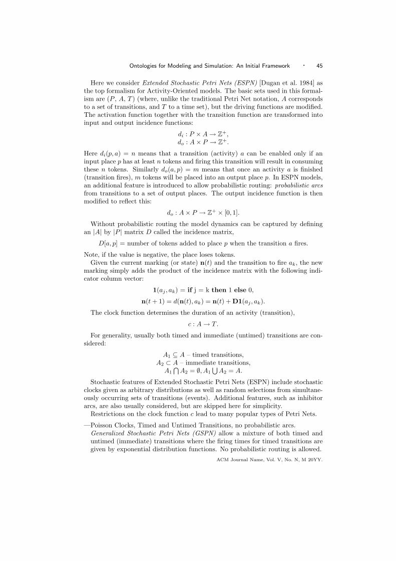
Ontologies for Modeling and Simulation: An Initial Framework · 45
Here we consider Extended Stochastic Petri Nets (ESPN) [Dugan et al. 1984] asthe top formalism for Activity-Oriented models. The basic sets used in this formal-ism are (P , A, T ) (where, unlike the traditional Petri Net notation, A correspondsto a set of transitions, and T to a time set), but the driving functions are modified.The activation function together with the transition function are transformed intoinput and output incidence functions:
di : P ×A → Z+,do : A× P → Z+.
Here di(p, a) = n means that a transition (activity) a can be enabled only if aninput place p has at least n tokens and firing this transition will result in consumingthese n tokens. Similarly do(a, p) = m means that once an activity a is finished(transition fires), m tokens will be placed into an output place p. In ESPN models,an additional feature is introduced to allow probabilistic routing: probabilistic arcsfrom transitions to a set of output places. The output incidence function is thenmodified to reflect this:
do : A× P → Z+ × [0, 1].
Without probabilistic routing the model dynamics can be captured by definingan |A| by |P | matrix D called the incidence matrix,
D[a, p] = number of tokens added to place p when the transition a fires.
Note, if the value is negative, the place loses tokens.Given the current marking (or state) n(t) and the transition to fire ak, the new
marking simply adds the product of the incidence matrix with the following indi-cator column vector:
1(aj , ak) = if j = k then 1 else 0,
n(t + 1) = d(n(t), ak) = n(t) + D1(aj , ak).
The clock function determines the duration of an activity (transition),
c : A → T .
For generality, usually both timed and immediate (untimed) transitions are con-sidered:
A1 ⊆ A – timed transitions,A2 ⊂ A – immediate transitions,
A1
⋂A2 = ∅, A1
⋃A2 = A.
Stochastic features of Extended Stochastic Petri Nets (ESPN) include stochasticclocks given as arbitrary distributions as well as random selections from simultane-ously occurring sets of transitions (events). Additional features, such as inhibitorarcs, are also usually considered, but are skipped here for simplicity.
Restrictions on the clock function c lead to many popular types of Petri Nets.
—Poisson Clocks, Timed and Untimed Transitions, no probabilistic arcs.Generalized Stochastic Petri Nets (GSPN) allow a mixture of both timed anduntimed (immediate) transitions where the firing times for timed transitions aregiven by exponential distribution functions. No probabilistic routing is allowed.
ACM Journal Name, Vol. V, No. N, M 20YY.

46 · John A. Miller et al.
—Poisson Clocks, Timed Transitions Only, no probabilistic arcs. If the transitionfiring times are given by exponential distribution function, we have a StochasticPetri Net (SPN).
—Deterministic Clocks. If the transition firing times are deterministic, we have aTimed Petri Net (TPN).
—Untimed Transitions Only. If all transitions are immediate (no time delay), wehave a classical Petri Net (PN).
One way to view the situation is to collect all the places coming into a transitionand imagine them as forming a queue. This will yield a Queuing Network (QN)view of the net. Such a net must allow probabilistic branching/routing. For a morecomplete discussion of the similarities and differences between QN and SPN see[Laclaustra 1990].
Activity Cycle Diagrams (ACD) [Tocher 1963; Hills and Poole 1969] can also beviewed as restricted versions of Stochastic Petri Nets (SPN). Timed transitions be-come activities and places become wait states (or queues). Topological restrictionsare imposed to make sure that the queues and activities alternate and the activitycycles are closed.
Appendix D - Object-Oriented Simulation
Object-Oriented Simulation (OOS) began quietly with Simula-67 in the 1960’s[Dahl et al. 1968]. As Smalltalk and more so C++ made object-oriented program-ming popular in the 1980’s, the 1990’s saw the reemergence of OOS in the 1990’swith numerous publications (e.g., [Joines et al. 1992; Zeigler 1990; Schwetman 1995;Cubert et al. 1997; Miller et al. 1997]). Unlike the traditional world-views, OOSalso relates to larger issues, such as model reuse, in the design of complex simulationmodels. As such, a simple self-contained formalism is not as straightforward as itis for the traditional world-views. Although there does not exist a clear and well-agreed upon definition of object-oriented simulation, in general, object-orientedprogramming can be used with any of the world-views. In particular, Kreutzer[1986] discusses how object-oriented programming techniques can be applied to theprocess-interaction world-view.
From a more formal point of view, Zeigler [1990] and Kim [Kim 1995] discuss howthe object-oriented paradigm fits with modular model specifications (which itself isbased on mathematical system theory). Modular system models can be adjustedto support encapsulation. Still, modular models have additional requirements thatgo beyond the object-oriented paradigm, such as providing a time base.
The key benefits of OOS come into play with the inheritance and aggregationhierarchies, which allow components or models to be combined or coupled (e.g.,coupled DEVS models). Although developing a comprehensive ontology for OOSwould be very useful, a full coverage should include topics that are closely related,such as agent-based simulation, component-based simulation, multi-modeling andmodular and hierarchical modeling. As this is a substantial undertaking, we leavea thorough treatment of OOS as future work. This is a natural division, since thecurrent work focuses on the basics of modeling, while the future work would addresshow multiple models are combined into complex simulation models.ACM Journal Name, Vol. V, No. N, M 20YY.

Ontologies for Modeling and Simulation: An Initial Framework · 47
Received Month Year; revised Month Year; accepted Month Year
ACM Journal Name, Vol. V, No. N, M 20YY.