ONT 400G CFP8 Modules - VIAVI Solutions
14
VIAVI Solutions Data Sheet VIAVI ONT 400G CFP8 Modules Introduction 400G technology is already being deployed under the emerging IEEE standard P802.3bs. With this innovation, test and measurement needs arise – from module development and validation, through hardware and IP integration to service deployment. The ONT 400G addresses all of these and provides a complete, scalable test solution for the whole 400G ecosystem which includes new modules, rates and technologies. This leading-edge instrument is ready for the 400G challenges today and future needs such as FlexO, FlexE and future OTN. The ONT 400G is based on the very latest IEEE 802.3 standards and industry MSA. Solution Highlights y Complete and comprehensive application coverage for troubleshooting physical layer and signal integrity issues through PCS/FEC to full Ethernet traffic. Real-world traffic applications allow full component validation in true application cases. No more limited and misleading unframed testing. y Helps quickly identify the root cause of errors, especially in the physical layer, with novel applications including advanced error analysis. Quickly identify operating margin with real FEC characteristics, no more blind guessing based on eye diagrams and raw BER. y Applications to cover complete IC and module validation – from unframed SERDES performance validation and diagnostics through to comprehensive coverage of complex IP blocks like FEC/PCS, packet throughput and QoS. y Integrated tools for complete CFP8 validation and turn up. Quickly validate operating margin and characteristics – accelerate testing and vendor selection. y Supports electrical access via 16 x NRZ Electrical Adapter, and PAM-4 via 8 x PAM-4 Electrical Adapter. y Ready to support future form factors like QSFPdd, OSFP etc. y Support for future flexible bandwidth needs such as FlexO and FlexE with the 5 x 100G QSFP28 ports dedicated to scalable bandwidth including bonding, subrating and channelization. Software options extend the applications addressed by ONT 400G, protecting your investment and help accelerate product development. Based on state- of-the art FPGA means quick updates to the latest test needs and standards. y Novel tools and accessories help troubleshoot the challenging areas of PAM-4 and FEC, core technologies which underpin 400G and future high-speed telecom and datacomm interfaces. Test grade adapters and accessories are perfectly matched to the ONT application, no more worries if 3rd party interconnects impact test results.
Transcript of ONT 400G CFP8 Modules - VIAVI Solutions
VIAVI SolutionsData Sheet
VIAVI ONT 400G CFP8 Modules
Introduction
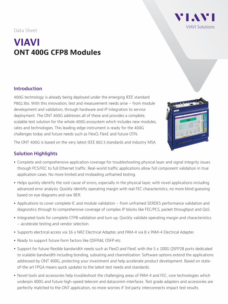
400G technology is already being deployed under the emerging IEEE standard P802.3bs. With this innovation, test and measurement needs arise – from module development and validation, through hardware and IP integration to service deployment. The ONT 400G addresses all of these and provides a complete, scalable test solution for the whole 400G ecosystem which includes new modules, rates and technologies. This leading-edge instrument is ready for the 400G challenges today and future needs such as FlexO, FlexE and future OTN.
The ONT 400G is based on the very latest IEEE 802.3 standards and industry MSA.
Solution Highlights
y Complete and comprehensive application coverage for troubleshooting physical layer and signal integrity issues through PCS/FEC to full Ethernet traffic. Real-world traffic applications allow full component validation in true application cases. No more limited and misleading unframed testing.
y Helps quickly identify the root cause of errors, especially in the physical layer, with novel applications including advanced error analysis. Quickly identify operating margin with real FEC characteristics, no more blind guessing based on eye diagrams and raw BER.
y Applications to cover complete IC and module validation – from unframed SERDES performance validation and diagnostics through to comprehensive coverage of complex IP blocks like FEC/PCS, packet throughput and QoS.
y Integrated tools for complete CFP8 validation and turn up. Quickly validate operating margin and characteristics – accelerate testing and vendor selection.
y Supports electrical access via 16 x NRZ Electrical Adapter, and PAM-4 via 8 x PAM-4 Electrical Adapter.
y Ready to support future form factors like QSFPdd, OSFP etc.
y Support for future flexible bandwidth needs such as FlexO and FlexE with the 5 x 100G QSFP28 ports dedicated to scalable bandwidth including bonding, subrating and channelization. Software options extend the applications addressed by ONT 400G, protecting your investment and help accelerate product development. Based on state-of-the art FPGA means quick updates to the latest test needs and standards.
y Novel tools and accessories help troubleshoot the challenging areas of PAM-4 and FEC, core technologies which underpin 400G and future high-speed telecom and datacomm interfaces. Test grade adapters and accessories are perfectly matched to the ONT application, no more worries if 3rd party interconnects impact test results.
2 ONT 400G CFP8 Modules
General Information
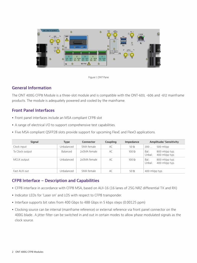
The ONT 400G CFP8 Module is a three-slot module and is compatible with the ONT-603, -606 and -612 mainframe products. The module is adequately powered and cooled by the mainframe.
Front Panel Interfaces
y Front panel interfaces include an MSA compliant CFP8 slot
y A range of electrical I/O to support comprehensive test capabilities.
y Five MSA compliant QSFP28 slots provide support for upcoming FlexE and FlexO applications.
Signal Type Connector Coupling Impedance Amplitude/ Sensitivity
Clock input Unbalanced SMA female AC 50 Ώ 200 … 500 mVpp
Tx Clock output Balanced 2xSMA female AC 100 Ώ Bal.: 800 mVpp typ.Unbal.: 400 mVpp typ.
MCLK output Unbalanced 2xSMA female AC 100 Ώ Bal.: 800 mVpp typ.Unbal.: 400 mVpp typ.
Fast AUX out Unbalanced SMA female AC 50 Ώ 400 mVpp typ.
CFP8 Interface – Description and Capabilities
y CFP8 interface in accordance with CFP8 MSA, based on AUI-16 (16 lanes of 25G NRZ differential TX and RX)
y Indicator LEDs for ‘Laser on’ and LOS with respect to CFP8 transponder.
y Interface supports bit rates from 400 Gbps to 488 Gbps in 5 kbps steps (0.00125 ppm)
y Clocking source can be internal (mainframe reference) or external reference via front panel connector on the 400G blade.. A jitter filter can be switched in and out in certain modes to allow phase modulated signals as the clock source.
Figure 1. ONT Pane
3 ONT 400G CFP8 Modules
Supported clocking modes:
Clock source mode (Default: Internal)Delta [ppm] Jitter
filter CommentRange Resolution
Internal +/- 500 0.01 N/A —
From Rx +/- 500 0.01 N/A —
Clock input“Direct Ref. In”
Jitter Filter Mode(Default: Low bandwidth)
Low bandwidth(BW ≤ 100 Hz)
+/- 500 0.01 N/A ONT 400G is clocked via jitter filter and synthesizer.
Jitter Filter Modes: Low (< 100 Hz), High
High bandwidth(BW ~ 1 MHz)
N/A N/A N/A Clock direct to ONT 400G. This setting allows for jitter modulation. Lowest intrinsic jitter.
Limitations:• No delta ppm possible.• User bit rate not supported.
Direct Clock Reference Input and Physical Layer Capabilities
Clock accuracy is directly linked to reference oscillator on mainframe or any user supplied clocking source.
Module power class – modules of up to 16 W can be powered and cooled in environments of up to 40º C ambient temperature. Modules up to 20 W can be supported if the airflow into the mainframe is unobstructed and temperature no more than 23º C ambient. The application GUI reports the current and power drawn by the module.
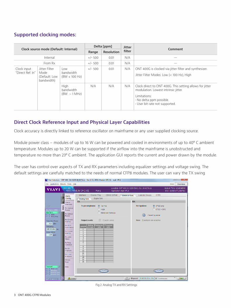
The user has control over aspects of TX and RX parameters including equalizer settings and voltage swing. The default settings are carefully matched to the needs of normal CFP8 modules. The user can vary the TX swing
Fig 2. Analog TX and RX Settings
4 ONT 400G CFP8 Modules
and pre-emphasis and address the RX equalizer DFE (Decision Feedback Equalizer) and CTLE (Continuous Time Linear Equalizer) mode (CTLE only, or CTLE + DFE). The settings can be applied to all 16 AUI lanes together or independently as required. Each individual AUI-16 lane can be independently inverted at both the RX and TX side.
y Module power supply voltage default is 3.3V as per MSA
y The ONT reports all core CFP8 parameters including both TX / RX clock offset and optical power (if supported by the CFP transponder & MDIO)
y Module supports transponder reference clocks of /40 and /160 rates with the default set to /160.
y For every clocking mode TX LTI (loss of timing information) clock status is provided.
y Module supports transponder TX output clocks of /40 and /160 rates with the default set to /40.
y TX and RX MCLK is supported in accordance with the CFP8 MSA.
y RX clock recovery is supported on all AUI-16 lanes — default is the lowest number lane with a valid clock content, user can manually select any desired lane.
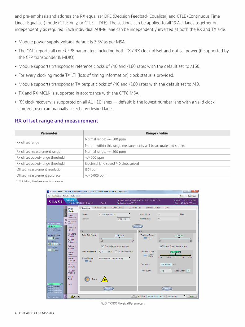
RX offset range and measurement
Parameter Range / value
Rx offset rangeNormal range: +/- 500 ppm
Note – within this range measurements will be accurate and stable.
Rx offset measurement range Normal range: +/- 500 ppm
Rx offset out-of-range threshold +/- 200 ppm
Rx offset out-of-range threshold Electrical lane speed /40 Unbalanced
Offset measurement resolution 0.01 ppm
Offset measurement accuracy +/- 0.005 ppm1
1. Not taking timebase error into account.
Fig 3. TX/RX Physical Parameters

5 ONT 400G CFP8 Modules
MDIO functions
MDIO modes
Normal (bus runs at set speeds and supports auto-increment read/write)
Relaxed (bus timing is gentler, every read/write is addressed and timing between commands is extended to support modules with limited capabilities)
Off (MDIO bus off – no MDIO commands; read, write, module RX and TX optical power reporting etc. not supported).
MDIO bus speed Default 4 MHz, “hardware validation” option supports 0.5, 0.8, 1.0, 1.333, 2.0, 2.29, 2.66, 3.2 and 4.0 MHz bus clocking
Unframed Testing
y Interface: AUI-16 NRZ
y Pattern modes: same pattern on all 16 lanes, user settable pattern per lane, pattern offset
y Patterns: PRBS31, PRBS23, PRBS15, PRBS13, PRBS9, PRBS7 and inverted, 8 Byte DW, SSPR Stress Pattern
y TX/RX lane modes: mute, invert, free lambda group lane mapping
y BER Estimation: per virtual lane, per lambda group
y Error Stress Test: Automatic test through all available test patterns / offset / skew values
Dynamic Skew Generation (Option 3076/97.32)
The optional dynamic skew application allows individual lanes to be skewed backward and forward. The dynamic skem generation is supported in higher layer applications including PCS/FEC and Ethernet.
Skew variation is supported for all Tx clocking modes.
Parameter Range / value
Range +/- 512 bit with respect to unskewed ‘reference’ lanes
Resolution 10 mUI
Slope 10 .… 10 000 mUI/s
Fig 4. Dynamic Skew Variation on selected lane(s)

6 ONT 400G CFP8 Modules
400GE Ethernet Testing
PCS Layer Specifications
Each lane is clocked from common clock
TX ignore link faults On/off
FEC Bypass Correction and Indication On/off
Lambda Groups assignment
TX/ alignment marker and RX reference alignment marker
Fully editable
RX Status Overview LOAMPS indication per lane, PCS Lane#, Lane Swap alarm, FEC correctable/uncorrectable, ITB, Errored Block, Link Down, L/R Fault
Fully flexible lane mapping
RX errors and alarms LOAMPS, LOA, Lane Swap, SER, Link down, FEC corr./uncorr. ones and zeroes
Full view of received alignment markers
Bit Error Rate Estimation for given confidence level (aggregate and per lane)
TX Alarm/Error insertion LOAMPS, SER, LF/RF
RX Block and FEC Error Statistics table and graphic format
Lane Skew static static up to 64,000 bits
Lane Skew dynamic (option) up to +/- 512 UI in 30 mUI steps
Fig 5. MAC/IP Traffic Generation
7 ONT 400G CFP8 Modules
MAC/IP Layer Specifications
Up to 256 flows , one user defined traffic profile, with IP and/or MPLS
Traffic profile Constant load, bursty, ramp, IMIX; bandwidth 0.1 ... 400,000,000 Mb/s, back to back frames
VLAN tags up to 2, VLAN tags user defined
MPLS labels up to 5, user defined
User defined payload up to 64 bytes, user defined preamble and SFD
Service Disruption measurementResolution frame
Result display number of frames, nanoseconds
Transfer Delay measurement with calibration capability
Resolution 0.1 ns
Throughput measurement and frame statistics
Alarm/Error insertion and analysis FCS, runt, oversized, invalid SFD, IP header error in single, burst and rate modes, per flow
TX Test Frame Errors Frame loss, mis-insertion, swap, duplication
Capture Modes direct, filtered; buffer size: 128 KByte; offline analysis with Wireshark
Auto Test Modes Preamble transparency, throughput
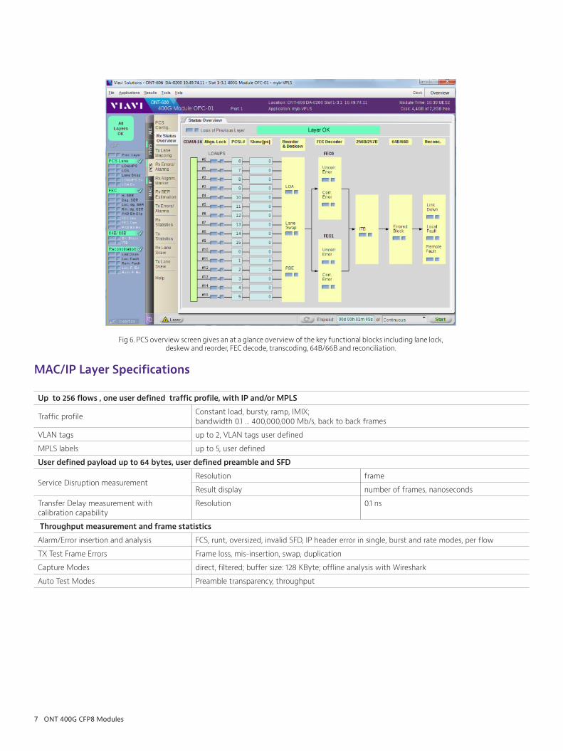
Fig 6. PCS overview screen gives an at a glance overview of the key functional blocks including lane lock, deskew and reorder, FEC decode, transcoding, 64B/66B and reconciliation.
8 ONT 400G CFP8 Modules
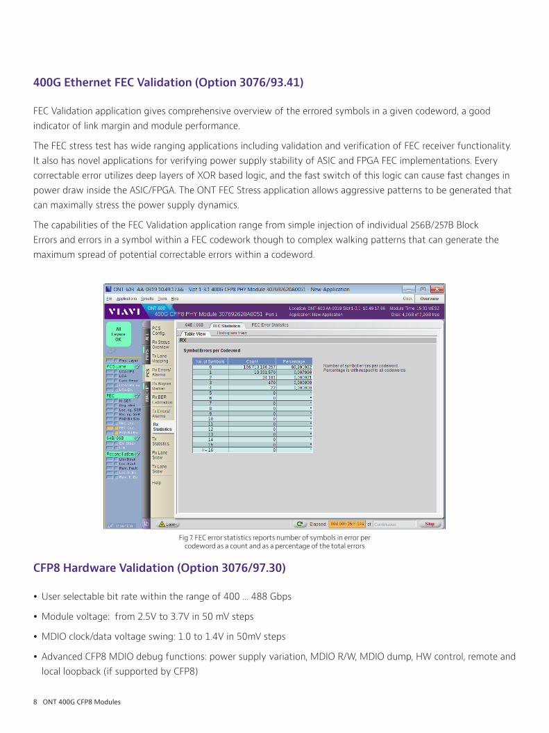
400G Ethernet FEC Validation (Option 3076/93.41)
FEC Validation application gives comprehensive overview of the errored symbols in a given codeword, a good indicator of link margin and module performance.
The FEC stress test has wide ranging applications including validation and verification of FEC receiver functionality. It also has novel applications for verifying power supply stability of ASIC and FPGA FEC implementations. Every correctable error utilizes deep layers of XOR based logic, and the fast switch of this logic can cause fast changes in power draw inside the ASIC/FPGA. The ONT FEC Stress application allows aggressive patterns to be generated that can maximally stress the power supply dynamics.
The capabilities of the FEC Validation application range from simple injection of individual 256B/257B Block Errors and errors in a symbol within a FEC codework though to complex walking patterns that can generate the maximum spread of potential correctable errors within a codeword.
CFP8 Hardware Validation (Option 3076/97.30)
y User selectable bit rate within the range of 400 ... 488 Gbps
y Module voltage: from 2.5V to 3.7V in 50 mV steps
y MDIO clock/data voltage swing: 1.0 to 1.4V in 50mV steps
y Advanced CFP8 MDIO debug functions: power supply variation, MDIO R/W, MDIO dump, HW control, remote and local loopback (if supported by CFP8)
Fig 7. FEC error statistics reports number of symbols in error per codeword as a count and as a percentage of the total errors
9 ONT 400G CFP8 Modules
Dynamic Skew Generation (Option 3076/97.32)
Unique feature to test signal integrity in the presence of phase variations between AUI-16 lanes, as they can occur in the network as a function of slight speed variations over temperature or other parameters.
This option allows to dynamically skew a selected AUI-16 NRZ lane over a wide range:
TX Dynamic Lane Skew
Maximum dynamic lane skew +/- 512 UI
Resolution 10 mUI
Slope 10 ... 10 000 mUI per second
Skew mode manual, triangleDynamic Skew is not supported for AUI-8 PAM4 signals
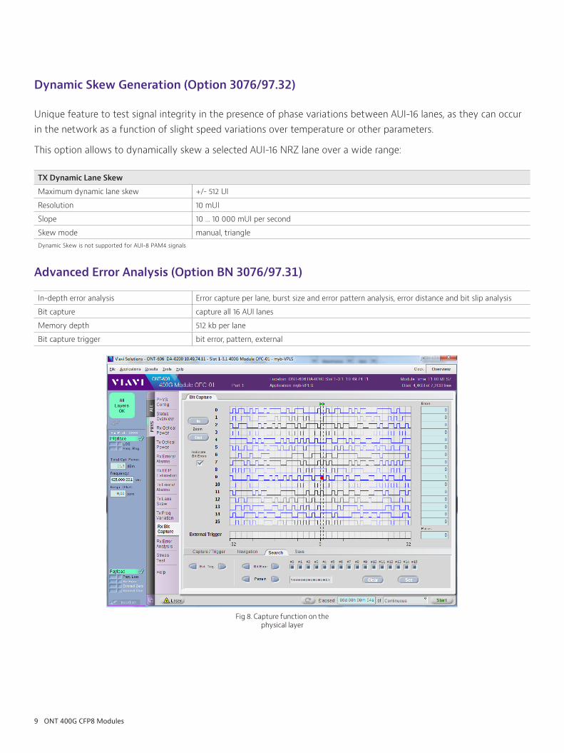
Advanced Error Analysis (Option BN 3076/97.31)
In-depth error analysis Error capture per lane, burst size and error pattern analysis, error distance and bit slip analysis
Bit capture capture all 16 AUI lanes
Memory depth 512 kb per lane
Bit capture trigger bit error, pattern, external
Fig 8. Capture function on the physical layer
10 ONT 400G CFP8 Modules
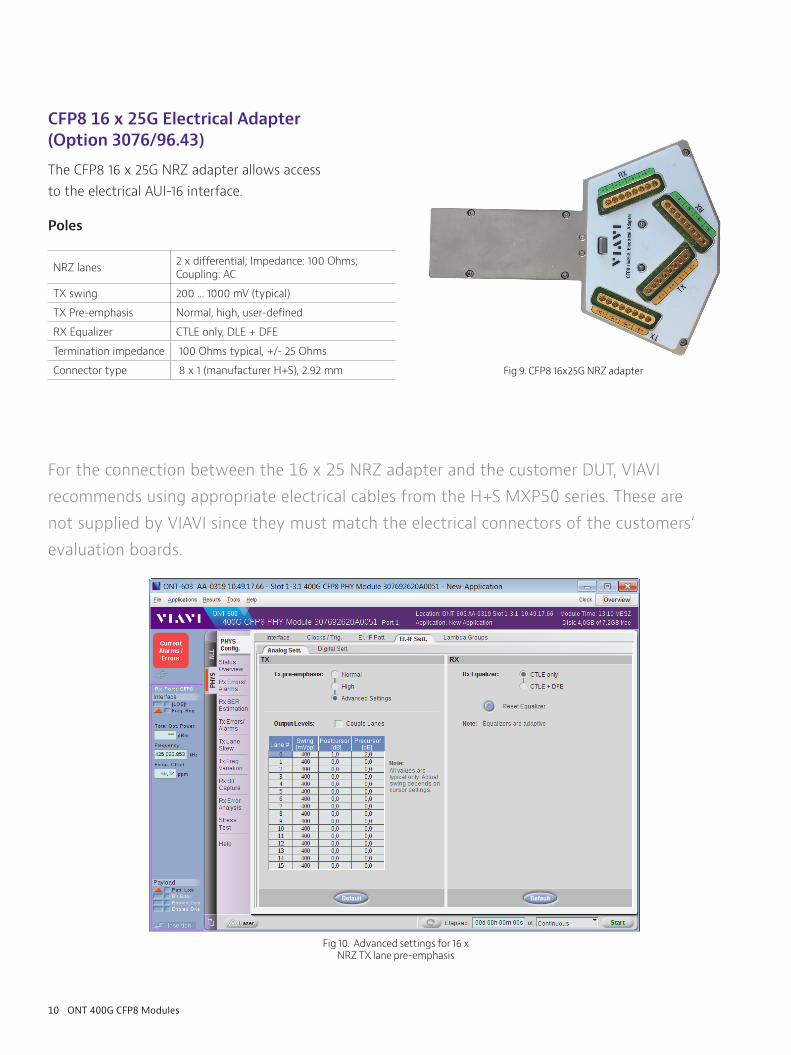
CFP8 16 x 25G Electrical Adapter (Option 3076/96.43)
The CFP8 16 x 25G NRZ adapter allows access to the electrical AUI-16 interface.
Poles
NRZ lanes 2 x differential; Impedance: 100 Ohms; Coupling: AC
TX swing 200 ... 1000 mV (typical)
TX Pre-emphasis Normal, high, user-defined
RX Equalizer CTLE only, DLE + DFE
Termination impedance 100 Ohms typical, +/- 25 Ohms
Connector type 8 x 1 (manufacturer H+S), 2.92 mm
For the connection between the 16 x 25 NRZ adapter and the customer DUT, VIAVI recommends using appropriate electrical cables from the H+S MXP50 series. These are not supplied by VIAVI since they must match the electrical connectors of the customers’ evaluation boards.
Fig 9. CFP8 16x25G NRZ adapter
Fig 10. Advanced settings for 16 x NRZ TX lane pre-emphasis
11 ONT 400G CFP8 Modules
Fig 13. Detailed view of TX pre-emphasis settings (per lane or “all lanes”)
Fig 11. CFP8 - 8 x 50G PAM-4 electrical adapter and calibration cables
Fig 12. (8 x 1) connector by H+S
Fig 12. Analogue settings for the PAM-4 adapter TX and RX
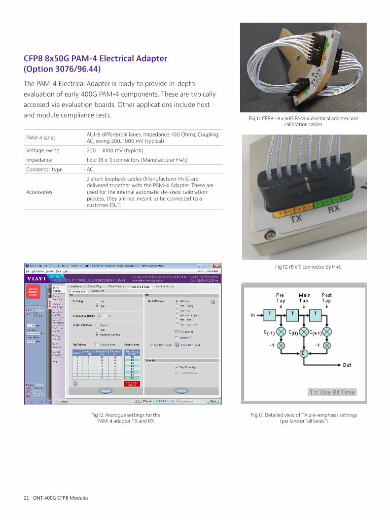
CFP8 8x50G PAM-4 Electrical Adapter (Option 3076/96.44)
The PAM-4 Electrical Adapter is ready to provide in-depth evaluation of early 400G PAM-4 components. These are typically accessed via evaluation boards. Other applications include host and module compliance tests.
PAM-4 lanes AUI-8 differential lanes; Impedance: 100 Ohms; Coupling: AC; swing 200...1000 mV (typical)
Voltage swing 200 ... 1000 mV (typical)
Impedance Four (8 x 1) connectors (Manufacturer H+S)
Connector type AC
Accessories
2 short loopback cables (Manufacturer H+S) are delivered together with the PAM-4 Adapter. These are used for the internal automatic de-skew calibration process, they are not meant to be connected to a customer DUT.
12 ONT 400G CFP8 Modules
PAM-4 TX Characteristics
The TX signal can be set to a standard default value that covers most practical cases. In addition, GUI allows access to advanced pre-emphasis values via the above dialogue. Output voltage will be in the range of 200 .... 1000 mVpp typical, depending on settings.
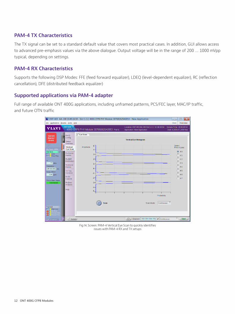
PAM-4 RX Characteristics
Supports the following DSP Modes: FFE (feed forward equalizer), LDEQ (level-dependent equalizer), RC (reflection cancellation), DFE (distributed feedback equalizer)
Supported applications via PAM-4 adapter
Full range of available ONT 400G applications, including unframed patterns, PCS/FEC layer, MAC/IP traffic, and future OTN traffic
Fig 14. Screen: PAM-4 Vertical Eye Scan to quickly identifies issues with PAM-4 RX and TX setups

13 ONT 400G CFP8 Modules
Advanced Error Analysis (Option 3076/97.31) can be used together with the PAM-4 adapter to quickly identify issues with areas like error burst length, critical for PAM-4 based interfaces with FEC:
Ordering Information:
400G Modules
3076/92.62 400G CFP8 Phy Module – CFP8 slot, 5 x QSFP28 slots, full physical layer test capabilities, 400G Ethernet SW
3076/92.64 400G CFP8 Data Module – CFP8 slot, 5 x QSFP28 slots, 400G Ethernet SW
3076/92.65 CFP8 QFlex Data Module – CFP8 slot, 5 x QSFP28 slots, to be combined with at least one SW option out of 3076/97.50 or 97.60 (under preparation)
3076/92.63 QFlex Data Module – 5 * QSFP28 slots, to be combined with at least one SW option out of FlexE or FlexO
Options and accessories
Options available on CFP8 QFlex Data Module and CFP8 Phy Module
3076/97.30 CFP8 Hardware Validation SW
3076/97.41 400G Ethernet FEC Validation SW
3076/96.43 CFP8 16x25G Electrical Adapter (limited functionality on Data Module)
Options available on CFP8 PHY Module only
3076/97.31 CFP8 Advanced Error Analysis SW
3076/97.32 CFP8 Dynamic Skew Generation SW
3076/96.43 CFP8 16x25G Electrical Adapter
3076/96.44 CFP8 8x50G PAM-4 Electrical Adapter
3076/96.45 CFP8 to QSFP-DD 8x50G PAM-4 Adapter (in preparation)
3076/96.46 CFP8 to OSFP 8x50G PAM-4 Adapter (in preparation)
3076/97.50 FlexE 100GBase-R SW with clients up to 100GE (in preparation)
3076/97.60 OTN FlexO OTUCn Bulk SW (in preparation)
Fig 15. Screen: PAM-4 Vertical Eye Scan to quickly identifies issues with PAM-4 RX and TX setups

© 2021 VIAVI Solutions Inc. Product specifications and descriptions in this document are subject to change without notice.Patented as described at viavisolutions.com/patents 400g-ds-opt-tm-ae30186280 902 0421
Contact Us +1 844 GO VIAVI (+1 844 468 4284)
To reach the VIAVI office nearest you, visit viavisolutions.com/contact
viavisolutions.com
VIAVI Solutions
Increase your productivity for up to 5 years with optional VIAVI Care Support Plans:
y Maximize your time with on-demand training, priority technical application support and rapid service. y Maintain your equipment for peak performance at a low, predictable cost.
Plan availability depends on product and region. Not all plans are available for each product or in every region. To find out which VIAVI Care Support Plan options are available for this product in your region, contact your local representative or visit: viavisolutions.com/viavicareplan
VIAVI Care Support Plans
Plan Objective Technical Assistance
Factory Repair
Priority Service
Self-paced Training
5 Year Battery and Bag
Coverage
Factory Calibration
Accessory Coverage
Express Loaner
BronzeCare
Technician Efficiency Premium
SilverCare
Maintenance & Measurement
AccuracyPremium *
MaxCare
High Availability Premium *
*5-year plans onlyFeatures


![400G+5G - img3.gelonghui.com · [Table_MainInfo][Table_Title] / 400G+5G [Table_Summary] 1 2 BAT 17% 40% ICP 3 400G 2019 2020 4 100G 400G (( ) 5G 1 4G 5G 6G/10G 25G 10G/100G 100G/200G/400G](https://static.fdocuments.us/doc/165x107/5e6c5d2df191f20be52e7612/400g5g-img3-tablemaininfotabletitle-400g5g-tablesummary-1-2-bat.jpg)