Online Shopping Mall
54
1 Project Report For Completion Of 4 th Semester Mini Project ONLINE SHOPPING for Department of Computer Applications, CUSAT Submitted By:- MAITREYEE 4 th semester,Reg No-95580020 DEPARTMENT OF COMPUTER APPLICATIONS, cusat
-
Upload
ankita-mukherjee -
Category
Documents
-
view
219 -
download
4
description
Documentation
Transcript of Online Shopping Mall

1
Project Report For Completion Of 4 th Semester Mini Project
ONLINE SHOPPING
for
Department of Computer Applications, CUSAT
Submitted By:-
MAITREYEE
4th semester,Reg No-95580020
DEPARTMENT OF COMPUTER APPLICATIONS,
cusat

2
CERTIFICATE
This is to certify that the project entitled
--ONLINE-SHOPPING-- submitted to Cochin University of Science
and Technology in partial fulfillment of the requirements for the
award of the degree of Master of Computer Applications is the
bona fide record of the project work
done by ----MAITREYEE-------------------- under our supervision
and guidance during ------------------- to -----------------.
Signature of Internal Guide Signature of External Guide
Name and Designation Name and Designation
Head of Department
Official Address
Internal Examiner External Examiner

3
ACKNOWLEDGEMENT
The satisfaction and euphoria that accompany the
successful completion of any task would be incomplete
without mentioning the names of people who made it possible, whose
constant guidance and encouragement crowns
all efforts with our success.
I extend my gratitude to Dr. K.V. Pramod,
Head- Department of Computer Applications, Cochin University
of Science and Technology, Kochi, Kerala for providing
me with excellent infrastructure and awesome environment
that laid potentially strong foundation for my professional life.
I would like to express my profound thanks to
Mr. A. SreeKumar, who guided me through out the project
tenure, provided me each and every details, references, and technical
helps without which it was impossible to complete
this project. I am also thankful to Professor Dr. B. Kannan, and
Mrs. S. Malathi for their help and guidance
throughout my project future.
Finally. I also wish to thank all guest faculties and non-teaching
staffs for supporting me during my whole project work.
SIGNATURE
4
SYNOPSIS: Title : ONLINE SHOPPING
Student’s Name : MAITREYEE
Venue of the Project : DCA, CUSAT
Duration : 4 months
Platform : Windows XP/Vista/7
Application Software
Front End : JSP
Back End : MYSQL

5
CONTENTS
1. Introduction
2. System Study
2.1 Existing System
2.2 Drawbacks in the Existing System
3. System Analysis
3.1 Proposed System
3.2 Scope
3.3 Need for the Proposed System
3.4 Feasibility Study
3.4.1 Technical Feasibility
3.4.2 Financial Feasibility
3.4.3 Operational Feasibility
4. Requirement Analysis
4.1 User Class and Characteristics
4.2 Functional Requirements
4.3 Performance Requirements
4.4 Non Functional Requirements
4.5 External Interfaces Requirements
4.6 General Constraints, Assumptions, Dependencies,
Guidelines

6
5. System Design Specification
5.1 Architectural Design
5.1.1 Data Flow Diagrams
5.1.2 Database Tables
5.1.3 User Case Diagrams
6. Testing
7. Software Quality Assurance Plan
8. Output Screen
Output of Pages
9. Conclusion
10. Scope for further development
11. Bibliography

7
1.INTRODUCTION
Online shopping is the process whereby consumers directly buy
goods, services etc. from a seller interactively in real-time without an
intermediary service over the internet.
Online shopping is the process of buying goods and services from
merchants who sell on the Internet. Since the emergence of the World
Wide Web, merchants have sought to sell their products to people who
surf the Internet. Shoppers can visit web stores from the comfort of their
homes and shop as they sit in front of the computer.Consumers buy a
variety of items from online stores. In fact, people can purchase just
about anything from companies that provide their products online.
Books, clothing, household appliances, toys, hardware, software, and
health insurance are just some of the hundreds of products consumers
can buy from an online store.
Many people choose to conduct shopping online because of the
convenience. For example, when a person shops at a brick-and-mortar
store, she has to drive to the store, find a parking place, and walk
throughout the store until she locates the products she needs. After
finding the items she wants to purchase, she may often need to stand in
long lines at the cash register.
Despite the convenience of online shopping, not everyone chooses to
purchase items and services online. Some people like the idea of
physically going to a store and experiencing the shopping process. They
like to touch the merchandise, try on clothing, and be around other
people. Online shopping doesn't permit shoppers to touch products or

8
have any social interaction. It also doesn't allow them to take the
merchandise home the same day they buy it.
Online shopping allows you to browse through endless possibilities, and
even offers merchandise that's unavailable in stores. If you're searching
for a niche product that may not be distributed locally, you're sure to
find what you're looking for on the internet. What's even more useful is
the ability to compare items, similar or not, online. You can search
through multiple stores at the same time, comparing material quality,
sizes and pricing simultaneously.
Shopping via the internet eliminates the need to sift through a store's
products with potential buys like pants, shirts, belts and shoes all slung
over one arm. Online shopping also eliminates the catchy, yet irritating
music, as well as the hundreds, if not thousands, of other like-minded
individuals who seem to have decided to shop on the same day.
Say 'goodbye' to the days when you stood in line waiting, and waiting,
and waiting some more for a store clerk to finally check out your items.
Online shopping transactions occur instantly-saving you time to get your
other errands done! Additionally, unlike a store, online shopping has
friendly customer service representatives available 24 hours a day, 7 days
a week to assist you with locating, purchasing and shipping your
merchandise.

9
2.SYSTEM STUDY Information systems projects’ originate from many reasons: to
achieve greater speed in processing data, better accuracy and improved
consistency, faster information retrieval, integration of business areas,
reduced cost and better security. The sources also vary project proposals
originate with department managers, senior executives and systems
analysis.
Sometimes the real origin is an outside source, such as a government
agency which stipulates a systems requiremetns the organisattion must
meet. When the request is made, the first systems activity, the
preliminary investigation, begins. The activity has three parts: request
clarification, feasibility study and request approval
2.1 Existing System:
The existing system was an automated system. But
It was found to be inefficient in meeting the growing demands
of population .
2.1.1 Drawbacks in the existing systems:
Disadvantage of the existing system:
Time Consuming
Expensive
Needed an agent
We have to out for that.

10
3.SYSTEM ANALYSIS
.
• This system is all about the converting the shopping
• system from manual to online.
• Customer can buy products online after login to the site.
• Administrator is adding product to database.
• Administrator can edit or delete the products
from the database.
• After buying and making payment the products are
send to customers address that he has given.
• Customer can write feedback for the product or services.
• Admin can see daily sell and feedback given by customer.
• Administrator is adding the delivery report to the
database.
• Both admin and customer can see the delivery report.
• 3.1 Purpose:
Online shopping tries to enhance access to care and
improve the continuity and efficiency of services. Depending on the
specific setting and locale, case managers are responsible for a
variety of tasks, ranging from linking clients to services to actually
providing intensive shopping and delivery services themselves
Main objective
• To shop wile in the comfort of your own home ,without having to step out of the door.
• sell at lower rate due to less over head. • provide home delivery free of cost. • No wait to see the products if someone else is taking that.

11
3.2 Scope:
This product has great future scope. Online shopping
Internet software developed on and for the Windows and later
versions environments and Linux OS. This project also provides
security with the use of Login-id and Password, so that any
unauthorized users can not use your account. The only Authorized
that will have proper access authority can access the software.
3.3 Need for the proposed system:
The online shopping (HOME SHOP) is an easy to maintain,
ready to run, scalable, affordable and reliable cost saving tool from
Software Associates suited for small, medium, and large shopping
complex and shopping malls.
Features and Benefits:
Providing security
Low cost
Basic computer knowledge required
Configurable and extensible application UI
design
The proposed system can be used even by the naïve users and it
does not require any educational level, experience, and technical
expertise in computer field but it will be of good use if the user has the
good knowledge of how to operate a computer.
3.4 Feasibility study:
A feasibility study is a short, focused study, which aims to
answer a number of questions:

12
Does the system contribute to the overall objectives of the
organizations?
Can the system be implemented using current technology and
within given cost and schedule constrains?
Can the system be integrated with systems which are already in
place?
3.4.1 Technical Feasibility:
Is the project feasibility within the limits of
current technology?
Does the technology exist at all?
Is it available within given resource constraints (i.e., budget,
schedule)?
3.4.2 Financial Feasibility:
Is the project possible, given resource constraints?
Are the benefits that will accrue from the new system worth
the costs?
What are the savings that will result from the system,
including tangible and intangible ones?
What are the development and operational costs?
3.4.3 Operational Feasibility:
Define the urgency of the problem and the acceptability
of any solution; if the system is developed, will it be used? Includes
people-oriented and social issues: internal issues, such as
manpower problems, labour objections, manager resistance,

13
organizational conflicts and policies; also external issues,
including social acceptability, legal aspects and government
regulations.
4. SYSTEM REQUIREMENTS SPECIFICATIONS
System requirements are expressed in a software
requirement document. The Software requirement specification
(SRS) is the official statement of what is required of the system
developers. This requirement document includes the requirements
definition and the requirement specification. The software
requirement document is not a design document. It should set out
what the system should do without specifying how it should be done.
The requirement set out in this document is complete and consistent.
The software specification document satisfies the following:-
1 It specifies the external system behaviors.
2 It specifies constraints on the implementation.
3 It is easy to change.
4 It serves as reference tool for system maintainers.
5 It record forethought about the life cycle of the system.
6 It characterizes acceptable response to undesired events.

14
4.1 User Class and Characteristics:
There are 3 types of user of this software-
1.General public
2. Customers 3.Administrator
1. General public can use the system to see the
product,their prices and quantity available. General user can not buy the products.
2. Customers are using for viewing and buying the
products. Customer can also write feedbacks for products and services
3. Administrators can add,edit & delete products.and provide services to the customer. Administrator can see the daily sell. Can also see the the feedback given by the customer. Administrator maintaining the deliveries.
4.2 Functional Requirements:
The System must provide following functionalities—
Keeping records of admission of customers.
keeping the records of products.

15
keeping the daily sell .
Storing the feedback given by the customer.
keeping details about the product it is delivered
or not. etc.
Storing the items selected by the customer in the
temporary storage.
4.3 Performance Requirements:
In order to maintain an acceptable speed at maximum
number of uploads allowed from a particular customer will be
any number of users can access the system at any time. Also
connections to the servers will be based on the criteria of
attributes of the user like his location, and server will be working
whole 24X 7 times.
4.4 Non Functional Requirements:
Following Non-functional requirements will be there in the
Insurance on internet:
i). Secure access of confidential data (customer’s
details).
ii). 24 X 7 availability.

16
iii). Better component design to get better performance
at
peak time.
iv). Flexible service based architecture will be highly
desirable for future extension Non functional
requirements define system properties and
constraints
It arise through user needs, because of budget
constraints or organizational policies, or due to the
external factors such as safety regulations, privacy
registration and so on.
Various other Non-functional requirements are:
1. Security
2. Reliability
3. Maintainability
4. Portability
5. Extensibility
6. Reusability
7. Application Affinity/Compatibility
8. Resource Utilization
4.5 External Interface Requirements:
4.5.1 User Interface:
User of the system will be provided with the Graphical user
interface, there is no command line interface for any functions of
the product. The user will get 2 pages
1. Login page followed by Password
17
4.5.2 Hardware Interface:
Hardware requirements for Insurance on internet will be same for
both the parties which are follows:
Processor: - Pentium I or above.
RAM: - 128 MB or above. HD: - 20 GB or above. NIC: - For each party
4.5.3 Software Interface:-
Software required to make working of product is:-
1. Operating System: Windows XP/vista/7 or later version,
Linux OS which supports networking.
2. JAVA development tool kit
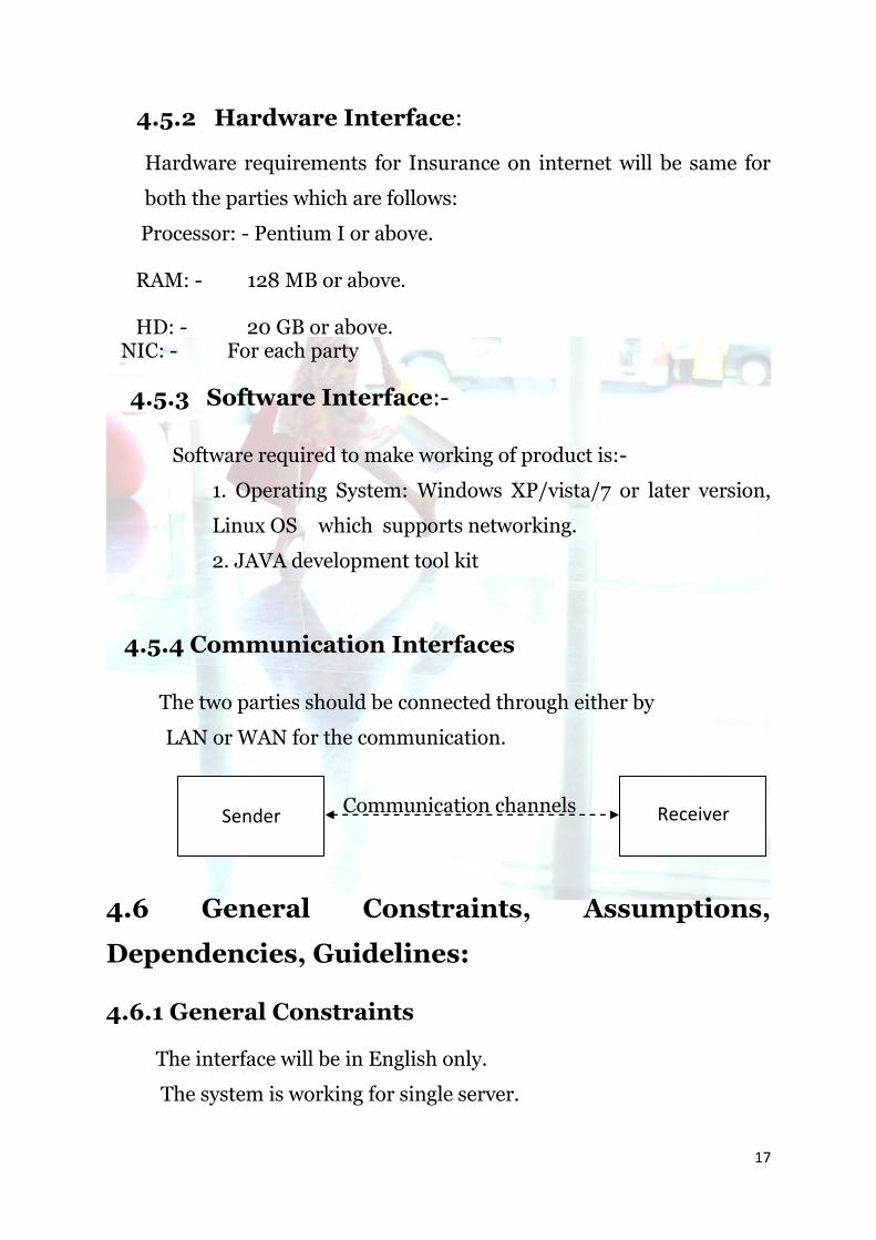
4.5.4 Communication Interfaces
The two parties should be connected through either by
LAN or WAN for the communication.
Communication channels
4.6 General Constraints, Assumptions,
Dependencies, Guidelines:
4.6.1 General Constraints
The interface will be in English only.
The system is working for single server.
Sender
Receiver

18
There is no maintainability or backup so availability will get
affected.
The system is a single user system.
GUI features available.
4.6.2 Assumptions and Dependencies
The product does require back-end database server MySQL
for storing the username and password for different types of
user of the system as well as various databases regarding
various insurance information.
Assumptions:
User must be trained for basic computer functionalities.
User must have the basic knowledge of English
The system must be able to respond to database software
within reasonable time.
Front-end (user interaction):
The product will require a computer with an application
program or with any other application program and an
communication channel.
The speed of the communication channel (if any) must be, at a
minimum 28.8 kbps in order to support message transfer in
reasonable time.

19
5. SYSTEM DESIGN SPECIFICATION
5.1 ARCHITECTURAL DESIGN
5.1.1 DATA FLOW DIAGRAMS:
Data flow diagrams (DFD) was first developed by
LARRY CONSTANTINE as way representing system
requirements in a graphical form; this lead to modular design.
A DFD describes what data flow (logical) rather than how they
are processed, so it does not depend on hardware, software,
data structure or file organization. It is also known as ‘bubble
chart’.
A Data Flow Diagrams is a structured analysis and design tool
that can be used for flowcharting in place of, or in association
with, information-oriented and process-oriented systems
flowcharts. A DFD is a network that describes the flow of data
and the processes that change, or transform, data throughout a
system. This network is constructed by using a set of symbols
that do not imply a physical implementation. It has the purpose
of clarifying system requirements and identifying major
transformations that will become programs in system design.
So it is the starting point of the design phase that functionality
decomposes the requirement specifications down to the lowest
level of detail.

20
The symbols used to prepare DFD do not imply a physical
implementation, a DFD can be considered to an abstract of the
logic of an information-oriented or a process-oriented system
flow-chart. For these reasons DFDs are often referred to as
logical data flow diagrams. The four basic symbols used to
construct data flow diagrams are shown below:
A rectangle represents a data source or
destination.
A directed line represents the flow of data
that
is data stream.
An enclosed figure, usually a circle or an
oval
bubble, represent a process that transforms
data streams.
An open-ended rectangle represents data
storage.
These are symbols that represent data flows, data sources, data
transformations and data storage. The points at which data are
transformed are represented by enclosed figures, usually
circles, which are called nodes. The principle processes that
take place at nodes are:

21
1. combining data streams
2. splitting data streams
3. modifying data streams.
CAD(CONTEXT ANALYSIS DIAGRAM)
ADMINONLINE
SHOPPING CUSTOMER
Gen.user
use
user
REQUESTS
ST DATA
BASE
SERVER
DATA BASE
REQUEST
ST DATA
BASE
customer
ADMIN.

22
1 LEVEL DFD FOR ADMIN
ADMINLOGIN
EDIT PRODUCTS
DELETE PRODUCTS
VIEW DAILY SELL
VIEW FEEDBACK
VIEW CUSTOMER
DETAIL
ADD PRODUCTS ADD
&VIEW DELIVERY REPORT
LOGIN TABLE
ID &PASSWORD
SELL TABLE FEEDBACK
USER TABLE
STORE TABLE
REJECTED IF NOT MACHED
PRODUCT DETAILS
DELIVERY DETAILS
CUSTOMER DETAILS
1 LEVEL DFD FOR CUSTOMER
CUSTOMERLOGIN
SEE SELECT
ED ITEMS
MAKE PAYMENT ADD
FEEDBACK
BUY PRODUCTS
VIEW DELIVERY REPORT
PRODUCT TABLE
LOGIN TABLE
ID &PASSWORD
ACCOUNT TABLE FEEDBACK
STORE TABLE
REJECTED IF NOT MACHED
DELIVERY DETAILS
TEMP TABLE

23
ER DIAGRAM
account
product
Buy product
make payment
user_name
email_id
Address
Sex
dob
user_id
prod_id
prod_name price
quantity
bank name
Customer details
acc no
phone no
write feedback
feedback
feedbacktype
feedback
comentpin no
STORE
ORDER_NO
REPORT

24
5.1. 2. DATABASE DESIGN:
A database design is a collection of stored data organized in such
a way that the data requirements are satisfied by the database. The
general objective is to make information access easy, quick, inexpensive
and flexible for the user. There are also some specific objectives like
controlled redundancy from failure, privacy, security and performance.
A collection of relative records make up a table. To design and store
data to the needed forms database tables are prepared. Two essential
settings for a database are:
Primary key: - The field that is unique for all the record
occurrences.
Foreign key: - The field used to set relation between
tables. Normalization is a technique to avoid
redundancy in the tables.

25
DATA BASE TABLE DESIGN:
Category table
Column name Data type Key constraint
Cat_id int Primary key not null
Cat_name Char(20) Not null
PRODUCT TABLE
Column name Data type Key constraints extra
Prod_id Int Primary key not null Auto_increment
Cat_id int Foriegn key Not null
Prod_name Char(20) Not null
Prod_descp Char(40) null
Price double Not null
Available int Not null
Add_date date Not null

26
Admin Login table
Column name Data type Key constraint
User_id int Primary key not null
password Char(20) Not null
Login table
Column name Data type Key constraint
User_id int Primary key not null
password Char(20) Not null

27
Store table
Column name Data type Key constraint
Order_no int Primary key not null
report Char(20) null
Temp table
Column name Data type Key constraint
Prod_id int Foriegn key not null
Prod_name Char(20) Not null
Price Double Not null
Items Int Not null
User_id Int Not null
Purchage_date Date Not null
Order_no Int null

28
User table
Column name Data type Key constraint extra
User_id int primary key not null
Auto_increment
Password Char(20) Not null
User_name Char(20) Not null
sex Char(6) Not null
Address Char(40) Not null
Date_of_birth date Not null
Date_of_register
date Not null
Phone_no Char(10) Not null
email Char(30) Not null
Feedback table
Column name Data type Key constraint
User_id int not null
type Char(10) Not null
feedback Char(10) Not null
comment Varchar(40) null
Feedback_date date Not null

29
Account table
Column name Data type Key constraint
Bank_name Char(20) not null
Account_no Char(20) not null
password Char(20) Not null
balance double Not null
Sell table
Column name Data type Key constraint
Prod_id Int not null
Prod_name Char(20) not null
price Double Not null
items Int Not null
User_id Int Not null
Purchage_date Date Not null
Order_no int Not null

30
5.1.3 USER CASE DIAGRAM:
User case diagrams are used to model the functional
interaction between users and system.
User1 Request to the
system
User2
(User Case Diagram)
Login Validate
User
Logout
Information
Perform
next task

31
6. TESTING Software Testing is an empirical investigation conducted
to provide stakeholders with information about the quality of the
product or service under test, with respect to the context in which
it is intended to operate. Software Testing also provides an
objective, independent view of the software to allow the business
to appreciate and understand the risks at implementation of the
software. Test techniques include, but are not limited to, the process
of executing a program or application with the intent of finding
software bugs. It can also be stated as the process of validating
and verifying that a software program/application/product meets
the business and technical requirements that guided its design
and development, so that it works as expected and can be implemented
with the same characteristics.
Software Testing, depending on the testing method employed,
can be implemented at any time in the development process, however
the most test effort is employed after the requirements have been
defined and coding process has been completed.

32
6.1 Unit Testing:
The primary goal of unit testing is to take the
smallest piece of testable software in the application, isolate
it from the remainder of the code, and determine whether it
behaves exactly as you expect. Each unit is tested separately before
integrating them into modules to test the interfaces between modules.
Unit testing has proven its value in that a large percentage of defects
are identified during its use.
Unit testing is a software verification and validation
method where the programmer gains confidence that individual
units of source code are fit for use. A unit is the smallest testable part of
an application. In procedural programming a unit may be an individual
program, function, procedure, etc., while in object-oriented
programming, the smallest unit is a class, which may belong to a
base/super class, abstract class or derived/child class.
Ideally, each test case is independent from the others:
substitutes like method stubs, mock objects, fakes and test harnesses can
be used to assist testing a module in isolation. Unit tests are typically
written and run by software developers to ensure that code meets its
design and behaves as intended. Its implementation can vary from
being very manual (pencil and paper) to being formalized as part of build
automation.

33
6.2 Integration Testing
Integration testing, also known as integration and testing
(I&T), is a software development process which program units are
combined and tested as groups in multiple ways. In this context, a unit is
defined as the smallest testable part of an application. Integration
testing can expose problems with the interfaces among program
components before trouble occurs in real-world program execution.
Integration testing is a component of Extreme Programming (XP), a
pragmatic method of software development that takes a meticulous
approach to building a product by means of continual testing and
revision.
There are two major ways of carrying out an
integration test, called the bottom-up method and the top-down
method. Bottom-up integration testing begins with unit testing,
followed by tests of progressively higher-level combinations of
units called modules or builds. In top-down integration testing,
the highest-level modules are tested first and progressively
lower-level modules are tested after that. In a comprehensive
software development environment, bottom-up testing is usually
done first, followed by top-down testing.
34
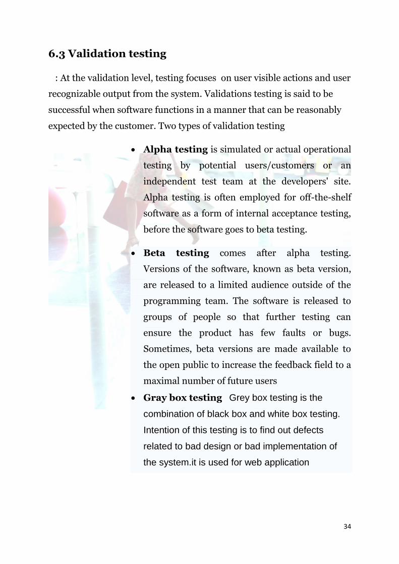
6.3 Validation testing
: At the validation level, testing focuses on user visible actions and user
recognizable output from the system. Validations testing is said to be
successful when software functions in a manner that can be reasonably
expected by the customer. Two types of validation testing
Alpha testing is simulated or actual operational
testing by potential users/customers or an
independent test team at the developers' site.
Alpha testing is often employed for off-the-shelf
software as a form of internal acceptance testing,
before the software goes to beta testing.
Beta testing comes after alpha testing.
Versions of the software, known as beta version,
are released to a limited audience outside of the
programming team. The software is released to
groups of people so that further testing can
ensure the product has few faults or bugs.
Sometimes, beta versions are made available to
the open public to increase the feedback field to a
maximal number of future users
Gray box testing Grey box testing is the
combination of black box and white box testing.
Intention of this testing is to find out defects
related to bad design or bad implementation of
the system.it is used for web application

35
7.Software Quality Assurance Plan
Each development and maintenance project should have a Software
Quality Assurance Plan that specifies its goals, the SQA tasks to be performed,
the standards against which the development work is to be measured, and the
procedures and organizational structure.
The IEEE Standards for the Software Quality Assurance Plans states that the
plan should contain the following sections:
1. Purpose
2. Reference documents
3. Management
4. Documentation
5. Standards, practices and conventions
6. Reviews and Audits
7. Configuration Management
8. Problem reporting and corrective action
9. Tools, techniques and methodologies
10. Code Control
11. Media Control
12. Supplier Control
13. Records collection, maintenance and retention.
1. Purpose, Scope and Overview:

36
The purpose of this Software Quality Assurance
(SQA) Plan is to establish the goals, processes, and responsibilities required to
implement effective quality assurance functions for the ONLINE SHOPPING.
The ONLINE SHOPPING Software Quality Assurance plan
provides the framework necessary to ensure a consistent approach to software
quality assurance throughout the project life cycle.
This plan establishes the SQA activities performed
throughout the life cycle of the ONLINE SHOPPING. Specifically, this SQA
Plan will show that the SQA function is in place for this project. It will show
that the SQA group has a reporting channel to senior management that is
independent of the project manager, the project’s software engineering group,
and software related groups that include Software Configuration Management
(SCM), System and Software Test, and Logistics.
The goal of the SQA program is to verify that all software and documentation to
be delivered meet all technical requirements.
2. Reference documents:
a. Software Quality Assurance, Principles and Practice: Nina S
Godbole.
3. Management:
An IEEE standard lays down three aspects that should be covered in the
Software Quality Assurance Plan:
Organization: The organization section includes the roles of the team
members, their hierarchy etc. It is important that the head of the Software
Quality Assurance (SQA) function in the organization has the adequate

37
authority to be able to perform independent verification that the processes
are adhered to.
The following describes the functional groups that influence and control
software quality.
a). Program Management/Line Management (Sponsor) is responsible for
the following items:
1. Identifying an individual or group independent from the
Project to audit and report on the project’s SQA function.
2. Identifying the quality factors to be implemented in the system
and software.
b). Project Management is responsible for:
1. Resolving and following-up on any quality issues raised by
SQA.
2. Identifying, developing and maintaining planning documents
Such as the Program Management Plan.
c). System Engineering is responsible for:
Implementing the engineering practices, processes, and procedures
as defined in program/project planning documents.
d). Software Design/Development is responsible for::
Identifying, implementing, and evaluating the quality factors to be
implemented in the software.
e). Software Test is responsible for:
Verifying, Implementing the software test practices, processes, and
procedures as defined in program/project planning documents.
f). System Test is responsible for:

38
Verifying the quality factors are implemented in the system
(software and hardware).
g). Logistics is responsible for:
1. Reviewing and commenting on the “” SQA Plan.
2. Implementing the quality program in accord ONLINE SHOPPING
assurance with this SQA Plan.
h). Software Configuration Management (SCM) is responsible for:
Implementing the SCM practices, processes, and procedures as
defined in reference and other program/project planning documents.
i). Independent Verification and Validation (IV& V) is responsible for:
Implementing the practices, processes, and procedures as defined
for IV&V in program/project planning documents.
j). Systems Engineering Process Office (SEPO) is responsible for:
1. Maintaining the SQA Process.
2. Ensuring SQA training availability.
3. Providing assistance in software process engineering and
software process improvement.
a) Tasks: An SQA task is performed in relationship to
what software development activities are taking place. One
or more SQA tasks can be performed concurrently until a
task is completed.
The following are the tasks of SQA plan:

39
Evaluate System Requirements Analysis Process
Evaluate System Design Process
Evaluate Software Requirements Analysis Process
Evaluate Software Design Process
Evaluate Software Tools
Evaluate Software Implementation and Unit Testing Process
Evaluate End-item delivery Process
Evaluate Configuration Management Process
b) Responsiblities: The project manager and
design/development teams have primary responsibility for
the quality controls applied during the development of the
software project.
The quality manager will:
Define the responsibilities of quality personnel in the form of quality
assurance procedures applicable to the project.
Agree to the quality plan with the project manager.
Approve the plan of the audits for the project which are to be carried out
by quality personnel.
Resolve any disagreement between the project manager and quality
personnel on matters relating to quality.
Review the activities performed by project personnel to ensure that the
requirements of the quality plan and quality procedures are being
satisfied.

40
Quality personnel will:
Carry out planned internal audits of the project to assess compliance with
quality objectives.
Agree on corrective action with the project manager for any
discrepancies, non-conformities found and ensure that corrective action is
taken.
Evaluate defect trends and take appropriate action.
4. Documentation:
The basic purpose of the documentation section of the Software Quality
Assurance Plan is to describe the documentation to be produced and how it is to
be reviewed. The documentation section normally includes the following:
Software Requirements Specification (SRS)
Software Design Description
Software Verification Plan
Software Verification report
Reference to Software Standards (ISO, CMM, IEEE etc) and procedures
mentioned and defined as in the Quality Manual and Quality
Management System
User guides, operators and programmers manual
Configuration Management Plan
Software Quality Objectives.
5. Standards, practices and conventions:

41
To verify the delivery of a fully conforming, high-quality product,
every individual assigned to the project will participate in quality assurance.
This section describes the procedures used by SQA to verify that the quality
assurance provisions of this SQA Plan and applicable standards, practices,
conventions, and metrics are met.
The following measurements will be made and used to determine the
cost and schedule status of the SQA activities: SQA milestone dates (planned)
a. SQA milestone dates (completed)
b. SQA work scheduled (planned)
c. SQA work completed (actual)
d. SQA effort expended (planned)
e. SQA effort expended (actual)
f. SQA funds expended (planned)
6. Reviews and Audits:
The review and audits sections of Software Quality Assurance Plan will state
which technical and managerial reviews will be undertaken and how they will
be carried out. The ANSI standard suggests that the following would be a
minimum set of reviews:
Software Requirements Specification Review: This review is held to
approve the document defining the software requirements specifications
and it aims to check the adequacy of the requirements.
Primary Design Review: The purpose of this review is to approve
formally, the software top-level design document.
42
Critical Design Review: The purpose of this review is to approve the
software detailed design document as a basis for further development
work.
Software Verification Review: The purpose of this review is to approve
the test plan. It is the evaluation of the adequacy and completeness of the
methods described.
Functional Audit: This is held to verify that all the requirements in the
software requirements specification have been met.
Physical Audit: This is held to verify that the software and its
documentation are internally consistent prior to delivery to the user.
In-Process Audit: In-Process audits of a sample design are held to verify
the consistency of the design.
7. Configuration Management:
This Configuration Management section of the Software Quality
Assurance Plan covers configuration identification, configuration control,
configuration status accounting, and configuration auditing.
8. Problem reporting and corrective action:
This section of the Software Quality Assurance plan describes the
system, which ensures that software problems are documented and resolved. It
should be a closed-loop system. All the problems should be promptly reported
at appropriate level, acted upon and resolved. Each problem should be analyzed
to determine its significance and causes and classified by category and each
problem must have severity level and a priority number.

43
For each problem, some corrective action and a target completion
date should be identified. The appropriate level of management should be made
aware of the problems and adverse trends. The corrective action taken will be
evaluated to ensure that it solved the problem without introducing any new
problems. Management should monitor the status of all unresolved problems.
9. Tools, techniques and methodologies:
Tools - SQA software tools include, but are not limited to,
operating system utilities, debugging aids, documentation aids, checklists,
structuring preprocessors, file comparators, structure analyzers, code analyzers,
standards auditors, simulators, execution analyzers, performance monitors,
statistical analysis packages, software development folder/files, software
traceability matrices, test drivers, test case generators, static or dynamic test
tools, and information engineering CASE tools.
Techniques - techniques include review of the use of standards,
software inspections, requirements tracing, requirements and design
verification, reliability measurements and assessments, and rigorous or formal
logic analysis.
Methodologies - methodologies are an integrated set of the above
tools and techniques. The methodologies should be well documented for
accomplishing the task or activity and provide a description of the process to be
used.
10. Code Control:
Code control includes the items listed below:
Identifying, labeling, and cataloging the software to be controlled
Identifying the physical location of the software under control
Identifying the location, maintenance, and use of backup copies

44
Distributing copies of the code
Identifying the documentation that is affected by a change
Establishing a new version
Regulating user access to the code.
11. Media Control:
The Media Control section of the Software Quality Assurance Plan
will describe how the media are to be protected from unauthorized access or
damage. Security threats to a software project come from the following
environmental factors:
Fire Damage
Water Damage
Energy Variations
Structural Damage
Pollution
Unauthorized Intrusion
Viruses and Worms
Misuse of Software, Data and Services.
12. Supplier Control:
Prior to any purchase of software to support the development
effort, SQA and project members will define and provide complete
requirements to the supplier/vendor. The Software Tool Evaluation Process
will be followed. Part of the evaluation process will require the supplier or
vendor to describe their technical support, handling of user questions and
problems, and software product upgrades.

45
13. Records collection, maintenance and retention:
SQA activities are documented by records and reports that
provide a history of product quality throughout the software life cycle.
Measurement data collected will be reviewed for trends and process
improvement. All SQA records will be collected and maintained in the
SDL or archival storage for the life cycle of the product.
8. SCREEN SHOTS

46
HOME PAGE
USER PAGE

47
LOGIN PAGE

48
ADMINSTRATOR PAGE
ADMINSTRATOR login

49
REGISTRATION PAGE

50
CUSTOMER DETAILS
PRODUCT PAGE

51
delivery report
FEEDBACK PAGE

52
9. CONCLUSION
This is to conclude that the project that I
undertook was worked upon with a sincere effort. Most of the
requirements have been fulfilled up to the mark and
the requirements which have been remaining, can be completed with a
short extension.
10. FUTURE SCOPE OF PROJECT
The project made here is just to ensure
that this product could be valid in today real challenging
world. Here all the facilities are made and tested. Currently the system works for limited number
of administrators to work. In near future it will be extended
for many types of insurance policies so that efficiency can be
improved.

53
11.BIBLIOGRAPHY
Books which I referred for the reference
Core Java 2 Volume I and II, by Cay S. Horstmann and
Gary Cornell
The Complete Reference JSP 2.0 by Hanna
Beginning JavaScript 2nd Edition, by Wilton
The Complete Reference MYSQL
The Complete Referance HTML.
Websites referred:-
http://www.google.co.in

54
THANK U