Distributed quantum computing utilizing multiple codes on ...

One-shot Entire Shape Scanning byUtilizing Multiple Projector-Camera Constraints of Grid Patterns
Nozomu KasuyaKagoshima University
Kagoshima, [email protected],jp
Ryusuke SagawaAIST
Tsukuba, [email protected]
Ryo FurukawaHIroshima City University
Hiroshima, [email protected]
Hiroshi KawasakiKagoshima University
Kagoshima, [email protected]
Abstract
This paper proposes a method to reconstruct the entireshape of moving objects by using multiple cameras andprojectors. The projectors simultaneously cast static gridpatterns of wave lines. Each of the projected patterns is asingle-colored pattern of either red, green, or blue. Thosepatterns can be decomposed stably, compared to multi-colored patterns. For the 3D reconstruction algorithm, one-shot reconstruction with wave grid pattern is extended forentire-shape acquisition, so that the correspondences be-tween the adjacent devices can be used as additional con-straints to reduce shape errors. Finally, multiple shapesobtained from the different views are merged into a singlepolygon mesh model using estimated normal informationfor each vertex.
1. Introduction
In recent years, as practical and reliable active 3D scan-ning devices develop rapidly, strong demands on captur-ing motions of humans or animals as a series of entire 3Dshapes is emerging [7]. Such 3D data can be applied to ges-ture recognition, markerless motion capture, digital fashion,and analysis of interaction between multiple humans or an-imals.
An important technical issue for the entire-shape scan ofa moving object is that a general 3D sensor can only cap-ture surfaces visible from one direction during one measure-ment; thus, acquiring an entire shape of an object is difficult.One approach that has been widely used is aligning a largenumber of cameras around the object, and reconstruct the3D shape with shape-from-silhouette [3, 13] . These pas-
sive measurement systems have achieved major successes;however, setting up those systems is complicated since theyneed a large number of cameras with broad networks andPCs, and the calculation time is huge.
Active entire-shape measurement systems could be al-ternatives to overcome the above problems of the passivemethods. However, since active methods use light sources,interferences between different illuminations become a ma-jor problem. Several methods that have been proposed un-til now can be largely separated into two types; one is touse different colors (i.e., wave-lengths), the other is high-frequency switching between multiple light sources withsynchronized camera capturing. Since the timing of captur-ing for multiple light sources are different, temporal inter-polation is needed for the integration of the shapes [20, 2],which may limit the extent of the applicability, the lattermethod is not suitable to scan fast-moving objects. There-fore, we take the former option in our method; however, theformer method also has problems.
If each of the light sources project a light pattern withmultiple colors, it is difficult to decompose the light pat-terns from the captured image in which multiple patternsare overlapped on a same surface; thus, devices that justuse single-colored pattern is suitable for the system, such asKinect. However, just aligning multiple devices with such aproperty also has problems, such as inconsistency betweenshapes measured by difference devices that come from cal-ibration errors of intrinsic or extrinsic parameters.
An approach to deal with this problem is using corre-spondences between multiple patterns projected from mul-tiple light projectors. As far as we know, there has been nomethod that performs this method with single-colored pat-terns. The method proposed by Furukawaetal. is related to
1

this approach [5]; however, it sometimes fails to decomposethe projected patterns because each pattern has two colors.
In this paper, we propose an active entire-shape mea-surement system in which single-colored patterns are pro-jected, and correspondences between multiple patterns areused. To achieve this, we extend one of the spatial-encodingmethods proposed by Sagawaetal. [17], which reconstructsshapes by projecting a static grid pattern of wave lines, toentire-shape acquisition. In the system, each projector emitsa single-colored waved-grid pattern with a color of eitherred, green, or blue, and the multiple grid-patterns are over-lapped. The target is captured from multiple cameras. Sim-ilarly to Sagawaet al. [17], the reconstruction is achievedby belief propagation (BP) on grid structure, except thatconsistencies between multiple devices to suppress errorsof the entire-shape are considered. The contributions of theproposed method is as follows:
• Decomposition of the pattern illuminated from differ-ent projectors becomes stable since single-colored pat-terns with RGB components are used.
• In the process of deciding stereo correspondences withgrid-based BP, correspondences between multiple pat-terns from different projectors captured from a singlecamera is used to stabilize the BP process.
• In the process of entire-shape reconstruction, corre-spondences between points on different depth im-ages generated with viewpoints of different projectorsare synthesized, and the errors for the correspondingpoints are minimized to improve the shape accuracy.
• Since the normal information for all the vertex is ob-tained simultaneously, a single and closed polygonmanifold mesh can be efficiently generated with Pois-son reconstruction methods(e.g., [10]).
From the above contributions, the complexity of the sys-tem is drastically reduced, the errors between multiple de-vices can be globally minimized to obtain consistent entire-shape, and dense and accurate reconstruction is achievedbecause errors of pattern decomposition is reduced.
2. Related Work
To capture the entire shape of moving objects, a silhou-ette based shape reconstruction method using a number ofcamera has been widely researched and developed [3]. Al-though the system have been constructed for various pur-poses over the world, there are several drawbacks that stillexist for the method, such as complicated and laborious taskfor the set-up and the calibration, low quality of silhouettebased reconstruction and huge computational cost.
One simple solution is to use an active light source todecrease the number of necessary devices. However, con-sidering the use of multiple lights for capturing the entireshape, several light sources are projected onto the same ob-ject and such severe interference of the multiple patternsmakes it impossible to reconstruct the shape with originalactive stereo algorithm. To solve the issue, two main ap-proaches are proposed. The first approach is quickly switch-ing the light sources and the other is using different wave-lengths or modulations for each light sources. In terms oflight switching approach, it is reported that 60 fps is real-ized for the fast moving human as a target [20, 2]. How-ever, since the technique essentially requires integration ofmultiple shapes to be captured at different times, applicableconditions are limited. Further, synchronous switching of anumber of light sources with multiple cameras is difficult.
For the technique using different wavelengths or modu-lations for each light source, if many wavelengths are over-lapped together at the same place, it is difficult to decom-pose them into the original component. Therefore, reducingthe number of wavelength for each light source is the key forthe approach. For example, since TOF method usually usesa laser with single wavelength, it is possible to use multipleof them to capture a wide range [11]. One problem is thatthe resolution of one-shot TOF scanner is low [14].
Another example is an active stereo method, which onlyuses a limited number of wavelength for scan [15]. In themethod, six sets of Kinect are used for capture the widerange of the scene. Since they use the same wavelength forall the devices, it sometimes fails to capture the object. Fur-ther, for both TOF and active stereo method, since shapesare reconstructed independently, there remains severe in-consistency during the integration of multiple shapes if cal-ibration has some errors.
To solve such inconsistency, instead of independent re-construction of each shape, simultaneous method for an en-tire shape scan is proposed [3]. In the method, multipleparallel lines are projected from each projector and eachcamera captures multiple patterns with their intersections.Since the intersection has some constraint on their originallines, the shape is reconstructed by using the constraints.One problem of the method is that it uses two colors foreach projector, and thus, it is overlapped on the same areaof the object surfaces, resulting in erroneous reconstruction.
Recently, active one-shot method is widely researchedand is being developed because of a strong demand to scanmoving objects [18, 21, 12, 1, 9, 16, 19]. Especially, single-color based one-shot scan is intensively researched since itis robust on image processing and can simplify the construc-tion of light source [1, 17]. In this paper, we extend thesingle color one-shot scanning technique for the purpose ofentire shape acquisition by using multiple sets of them.

Figure 1.The proposed system captures entire shape by using mul-tiple cameras and projectors.
Figure 2.An example of input images
3. Overview
The proposed system consists of multiple cameras andprojectors as shown in Fig.1. Each projector casts a staticwave-grid pattern proposed in [17]. The cameras captureimages synchronously, but no synchronization between acamera and projectors is required because the projected pat-tern does not change. A 3D shape at the moment of im-age acquisition is reconstructed from the single frame ofthe cameras.
The proposed method reconstructs a shape basically us-ing a pair of a camera and projector neighboring each other.Since a camera shares the field of view with multiple pro-jectors in the system, multiple patterns from different pro-jectors can be captured by a camera. In doing so, it is nec-essary to recognize the correspondence between projectorand detected pattern. While lines of multiple colors are pro-jected for reconstruction from each projector in [6], the re-construction with wave-grid pattern uses single-colored pat-tern for a projector. In this paper, we can therefore assigndifferent colors for the projectors. Because an off-the-shelfvideo projector can cast RGB colors, we locate the projec-tors so that neighboring projectors do not use the same col-ors as shown in Fig.1. Fig.2 shows an example of inputimages of the system with 6 cameras and 6 projectors. Thedetails of grid detection from the images are described inSec.4.
The second step is grid-based active stereo with multiplecameras and projectors, which finds the correspondence ofintersection points of the grid patterns (grid points) betweencameras and projectors. Our method is based on the methodproposed in [17], which uses one camera and one projec-
Orig
inal
com
pone
ntva
lues
Red
Blu
e
Com
pone
nts
afte
rsa
tura
tion
Red
Blu
e
Figure 3.The extraction of red and blue patterns is improved bysaturating the colors.
tor. If we use multiple cameras and projectors, additionalconstraints on the correspondence between two cameras, ortwo projectors can be introduced. The details of grid-basedstereo are explained in Sec.5.
The third step is optimization of correspondence by us-ing all pixels of cameras and projectors. The correspon-dence given by grid-based stereo is used as initial value andinterpolated by using all pixels to obtain dense 3D shape.The problem becomes multi-view stereo with cameras andprojectors, but it is simplified due to pattern projection be-cause initial guess and visibility check are given by grid-based stereo. The detail is described in Sec.6.
4. Detecting Grid Patterns from Multiple Pro-jectors
A grid pattern consists of wave lines of two directionsthat are perpendicular to each other. The projected patternsare first detected as curves in a captured image, and thegrid points are calculated from the intersection points of thecurves. Since the connection of grid points is used for find-ing correspondences, it is necessary to discriminate wavelines of different directions. We use the method of curvedetection based on belief propagation proposed by Sagawaet al. [16]. The method separately detects the lines of twodirections even if they have the same color.
Since multiple patterns are observed in a camera image,it is required to recognize which projector casts the pattern.
We use the colors for this purpose. The projected patterncan be red, green, or blue because commercial video projec-tors are used in our experimental system. The RGB spectraof both camera and projector usually overlap each other andit causes the crosstalk between the color components of thecaptured image. In Fig.3, we want to extract the patternsprojected as red and blue patterns from projectors in thisimage, while the projectors of green pattern are not usedbecause they are far from the camera to find its correspon-dence. If we detect lines by using red and blue componentsof the input image, the results are affected by the green pat-tern. The green lines are detected in the result of blue com-ponent at the side of the head (white circled).
To determine which projector a pattern is emitted from,we saturate the colors before grid detection as follows:
(h, s, v) = RGB2HSV(r, g, b)
(r′, g′, b′) = HSV2RGB(h, 1, v), (1)
where RGB2HSV and HSV2RGB are functions that con-verts between RGB and HSV color space, and colors arerepresented in the range of[0, 1]. By saturating the colors,minor components are suppressed. It is avoided that greenlines are detected in blue components.
5. Grid-based Active Multi-view Stereo
This section describes the proposed method of grid-based active stereo. It is based on a method proposed bySagawaet al. [17]. The basic system has a single projectorand a single camera (1C1P). If two cameras can be used, amethod that extends the basic method is proposed in [8] toimprove the robustness and accuracy by introducing addi-tional constraint between cameras. Since we have multiplecameras and projectors in this paper, more constraints canbe added to the scheme for finding correspondence on thegraph created by the grid patterns.
5.1. Finding Correspondence with Wave Grid Pat-tern between Camera and Projector
If the system is calibrated, the epipolar line in the projec-tor image that corresponds to a grid point in the camera im-age can be calculated. The true corresponding point of thegrid point on the projector image is the one from intersec-tion points on the epipolar line. First, the method collects allintersection points on the epipolar line as the candidates ofcorrespondence. Since the grid points are connected by thedetected curves, the grid points are regarded as nodes of agraph. The problem of finding correspondence becomes theone that chooses the best candidate assigned to each node.
Now, the grid graph detected in camerai consists ofnodespi ∈ Vi, edges by curve detection(pi, qi) ∈ Ui,wherepi andqi are grid points,Vi is the set of grid points,
grid graph
on camera i
Projec!on
to camera j
Epipolar line
of
Epipolar line
of
Projector
Camera i Camera j
: a candidate
: a candidate
: a node of
camera i
incorrect edge
edge between
cameras
edge between
to camera j
between
incorrect edge
cacameras
edge between
cameras
Object surface
: a node of
camera j
Search area of near
nodes from
grid graph
on camera j
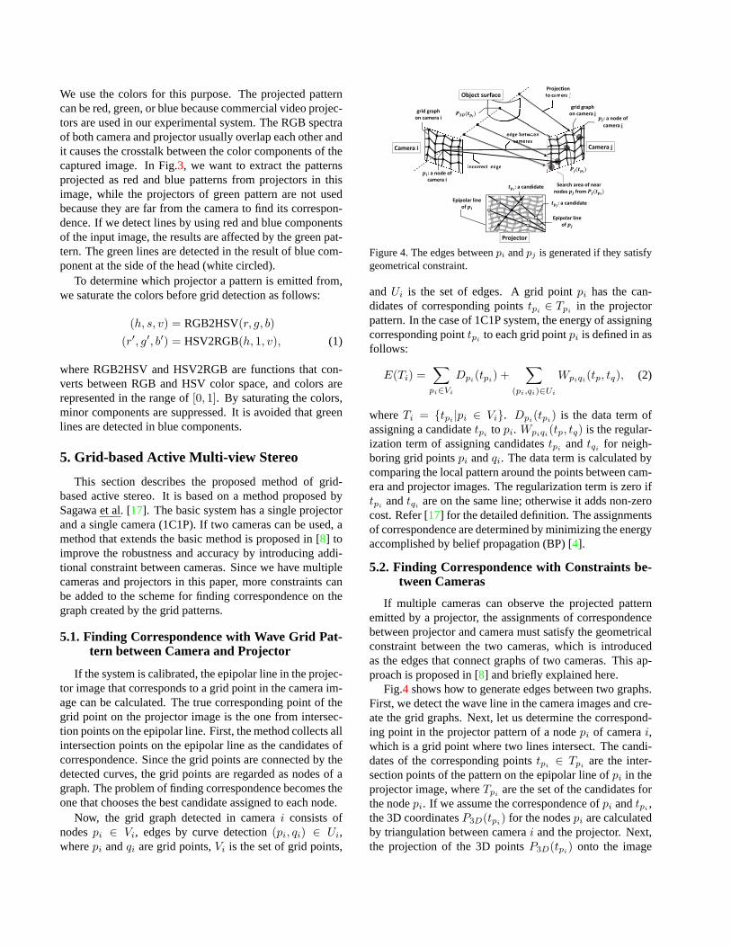
Figure 4.The edges betweenpi andpj is generated if they satisfygeometrical constraint.
andUi is the set of edges. A grid pointpi has the can-didates of corresponding pointstpi ∈ Tpi in the projectorpattern. In the case of 1C1P system, the energy of assigningcorresponding pointtpi to each grid pointpi is defined in asfollows:
E(Ti) =∑pi∈Vi
Dpi(tpi) +∑
(pi,qi)∈Ui
Wpiqi(tp, tq), (2)
whereTi = {tpi |pi ∈ Vi}. Dpi(tpi) is the data term ofassigning a candidatetpi to pi. Wpiqi(tp, tq) is the regular-ization term of assigning candidatestpi
andtqi for neigh-boring grid pointspi andqi. The data term is calculated bycomparing the local pattern around the points between cam-era and projector images. The regularization term is zero iftpi andtqi are on the same line; otherwise it adds non-zerocost. Refer [17] for the detailed definition. The assignmentsof correspondence are determined by minimizing the energyaccomplished by belief propagation (BP) [4].
5.2. Finding Correspondence with Constraints be-tween Cameras
If multiple cameras can observe the projected patternemitted by a projector, the assignments of correspondencebetween projector and camera must satisfy the geometricalconstraint between the two cameras, which is introducedas the edges that connect graphs of two cameras. This ap-proach is proposed in [8] and briefly explained here.
Fig.4 shows how to generate edges between two graphs.First, we detect the wave line in the camera images and cre-ate the grid graphs. Next, let us determine the correspond-ing point in the projector pattern of a nodepi of camerai,which is a grid point where two lines intersect. The candi-dates of the corresponding pointstpi ∈ Tpi are the inter-section points of the pattern on the epipolar line ofpi in theprojector image, whereTpi are the set of the candidates forthe nodepi. If we assume the correspondence ofpi andtpi
,the 3D coordinatesP3D(tpi) for the nodespi are calculatedby triangulation between camerai and the projector. Next,the projection of the 3D pointsP3D(tpi) onto the image

Correspondence is found
No correspondence for this node
pilpik
Pa!ern from projector lPa!ern from projector k
φ
Figure 5.The edges between two graphs in a camera image aregenerated.
of cameraj is Pj(tpi) as shown in Fig.4. If the nodepj ofcameraj is close toPj(tpi), pi andpj can be correspondingpoints. FourP3D(tpi) are projected onto cameraj in Fig.4.Since the leftmostPj(tpi) has no nodes in the search area,no candidate of correspondence is found. While the right-most one has a nodepj in the search area, the node does nothave the same candidatetpi in Tpj . Since the middle twoprojections satisfy the above condition, their nodes are con-nected topi. Once the edges between two cameras connecttheir graphs, they become a single graph, which enables usto simultaneously optimize the correspondences search oftwo cameras.
By using the constraint between cameras, the energy ofthe edges between cameras is defined as follows:
Xpipj (tpi , tpj ) =
{0 tpi = tpj
µ otherwise,(3)
whereµ is a user-defined constant.
5.3. Finding Correspondence with Constraints be-tween Projectors
The proposed system uses multiple projectors. If the pro-jected area overlapped with each other, the correspondencebetween projectors can be detected by using camera images.Fig.5 shows a situation that two patterns are overlapped ina camera images. If two grid points of different patternsare projected on the same pixel of the camera, it means thatthe two points of projectors corresponds each other. In thatcase, the two points have the same depth from the camera.Since it is not so frequent case that two points are projectedonto the exact same pixel, we determine the correspondingpoint pik ∈ Vik of camerai for the projectork the by find-ing pil ∈ Vil of of camerai for the projectorl that satisfythe following condition:
D(pik, pil) < ϕ, (4)
whereD(a, b) is the distance between pointsa andb, andϕis the radius of search area aroundpik.
The corresponding nodes of two graphs are connected asthe dotted lines shown in Fig.5. Therefore, the two graphsbecome one and the assignments are simultaneously opti-mized by minimizing the energy. The energy of the edgesof projector-projector correspondence is defined as follows:
Zpikpil(tpik
, tpil) = τ |di(P3D(tpik
))− di(P3D(tpil))|,
(5)wheredi(P3D) is the depth of the 3D pointP3D in the co-ordinate of camerai, andτ is a user-defined weight.
The total energy with multiple cameras and projectors isdefined by the following equation:
E(T ) =∑i
∑k∈Ap(i)
E(Tik) (6)
+∑k
∑i∈Ac(k),j∈Ac(k)
∑(pik,pjk)∈Sijk
Xpikpjk(tpik
, tpjk)
+∑i
∑k∈Ap(i),l∈Ap(i)
∑(pik,pil)∈Qikl
Zpikpil(tpik
, tpil)
,
whereAp(i) is the set of projectors that share the field ofview with camerai, Ac(k) is the set of cameras that sharethe field of view with projectork. Sijk is the set of edgesbetween camerasi andj given by the pattern of projectork. Qikl is the set of edges between projectorsk andl in theimage of camerai.
6. Generating Dense Shape by Integrating AllCameras and Projectors
The grid-based stereo in the previous section gives sparsecorrespondences for the grid points of projected patterns.The next step is to generate dense correspondences by us-ing all pixels and a single dense intricate shape by using allcameras and projectors. To integrate the information of allcameras, it is necessary to check the visibility of each 3Dpoints from cameras, which is a common problem of multi-view stereo. In our proposed system, however, the issue canbe simplified because the visibility from a projector is givenfrom the projected pattern.
The proposed integration consists of three steps. Thefirst step is to generate dense range images from the viewpoint of projectors. The second step is to optimize the rangeimages to minimize the errors with camera images and thediscrepancy between range images. Third, all range imagesare merged into a single mesh model.
6.1. Generating Range Image for Each Projector
Once a grid pattern is detected as that of the projectors,it is obvious that the detected points are visible from theprojector. Because the correspondence between camera and

Camera i
Camera j
Projector
mask i
mask j
Figure 6.The range image from the viewpoint of projector is gen-erated.
Projector kProjector l
Camera i
mask l
mask k
p3Dk
rl0
rl1
rl2
rk
p3Dkp3Dl0 p3Dl1
p3Dl2
Range data kRange data l
Figure 7.The difference between two range data is minimized byfinding the correspondence between projectors.
projector is roughly known by grid-based stereo, a rangeimage from the view point of the projector can be created.If the pattern from a projector is observed by multiple cam-eras, it is easy to merge the information as a range imagewithout considering the visibility. This approach is pro-posed in [8] and briefly explained here.
Fig.6 shows the situation that a grid pointtp of the pro-jector pattern has correspondences with points,pi andpj , ofboth two cameras. Two 3D points,p3Di andp3Dj , are cal-culated by the two correspondences, which usually do notcoincide due to the errors of image processing and calibra-tion. We integrate the depths,di anddj , from the viewpointof the projector by averaging them. To generate a denserange image, the depthdr for a pixel r is calculated byweighted average of depths of grid points inside the circleof radiusR aroundr. The mask image is created during thecalculation of the range image. The pixels inR is markedas valid for camerai.
6.2. Simultaneous Optimization of Multiple RangeImages
Next, we optimize the depths of all range images by min-imizing the energy. The energy proposed in [8] consists ofthe data term and regularization term. The data term is cal-culated by the difference of intensities between the cameraand the projector, and the regularization term is defined byusing the curvature around each vertex of the mesh model.Now, we have multiple range images and optimize them si-
(a) (b) (c) (d)Figure 8.3D reconstruction of two static objects:(a) input images,(b) grid-based reconstruction, (c) range data of multiple projectors,and (d) integrated shape.
multaneously. If two range images are overlapped with eachother, the shapes should coincide, which can be used addi-tional constraint to optimize the depths.
Fig.7 shows a situation that two range data of projectork andl overlap. A 3D pointp3Dk is calculated from a pointrk of projectork. The point overlaps with projectorl ifthe projection ofp3Dk is in the mask for projectorl. Then,p3Dk is projected onto the image of projectorl. If it is insideof a triangle formed by three points,rl0, rl1 andrl2, theybecome the corresponding points.
Now, the depth at a pointr is dr, and we consider∆dr,which is the small movement ofdr, which is used to up-date the depth during iterative minimization. The energy isdefined by using∆dr as follows:
E(∆D) =∑k
EI + α∑k
ES + β∑i
∑k,l∈Ap(i)
EP , (7)
EP =∑rk
∑rln∈G(rk)
(P3Dk(∆drk)− P3Dln(∆drln ))2,
where∆D is the set of∆dr. EI andES are the data andregularization terms, respectively. Refer [8] for the detailedexplanation. EP represents the constraint between rangeimages. G(rk) is the function to find the correspondingpoint rln of rk. P3D(∆dr) means the 3D point afterp3Dmoves∆dr along the line of sight.dr for each pixel is it-eratively updated by adding∆dr that minimizes the errorE(∆D) in non-linear minimization manner.
Finally, a single mesh model is created from the set ofmultiple range data. In this paper, we apply Poisson recon-struction proposed in [10] to merge range data.
7. Experiments
We have conducted experiments to confirm the effec-tiveness of the proposed method. The contribution of this

(a) (b) (c)Figure 9.The differences of the basic method (b) and the proposedmethod (c) from the reference shape (a) are shown by color.
Table 1.The numbers of incorrect correspondences are comparedby changing the constraint used in the grid-based stereo: (a) man-nequin, (b) plaster figure.
Total Incorrect matchesNum. Basic w/ X w/ Z w/ X,Z
(a) 4950 271 100 101 69(b) 2803 308 91 150 75
Table 2.The difference from the reference shape is evaluated bychanging the constraint used. The unit is millimeter.
Basic w/ X w/ X,Z w/ X,Z,Ep
2.960 2.867 2.694 2.686
paper is to improve robustness and accuracy by introduc-ing additional constraints to the framework of grid-basedstereo, and we show that the computational time is suffi-ciently low to process many frames as one of advantages ofusing the active approach. In the experiments, we used sixcameras of 1600× 1200 pixels that capture images at 30frames/second, and six liquid crystal projector 1024× 768pixels, which are placed around the target objects. The dis-tance of objects from cameras and projectors is about 2.0min the experimental system.
First, we captured static objects and evaluated the robust-ness and accuracy of finding correspondence. Fig.8 showsthe results of two static objects. (a) is one of input images.(b) is the result of grid-based stereo, and (c) is the denserange data after optimization. (d) is the merging result ofthe range data.
We evaluate the robustness of finding corresponding gridpoints by adding new constraints proposed in this paper.The number of incorrect matches is counted for the resultsobtained by changing the constraint used in the grid-basedstereo. Table1 shows the results of two objects shown inFig.8. The basic method does not use the both constraints,Xpikpjk
andZpikpilin Eq.(6). We tested to use eitherX
or Z to compare with the proposed method that uses thebothX andZ. The number of incorrect matches is clearlyreduced by the additional constraints. The number of incor-rect matches on the proposed method is about one fourth ofthe basic method.
Next, we evaluated the accuracy by calculating the dif-
Table 3.Computational time for reconstruction in seconds.Mannequin Plaster figure
Grid detection 2.518 2.463Grid-based stereo 0.517 0.381
Optimization 0.256 0.228Integration 4.205 4.159
Total 7.498 7.233
ference from the reference shape obtained by a close-range3D scanner, which is shown in Fig.9(a). The height of thefigure is about 0.6m. The differences are shown by colorin the basic method (b) and the proposed method (c). Thegreen area, which indicates that the difference is small, isincreased in (c) compared to (b). The average difference issummarized in Table2. Ep means the constraint used inEq.(7) of the optimization. The accuracy is improved byadding the constraints.
One of the advantage of the proposed method is thetwo-step approach for finding correspondence that roughestimation is done by grid-based stereo and dense shapeis obtained by optimization. Moreover, the algorithm iseasy to be parallelized by using GPU. The computationaltime for each step of the algorithm is summarized in Table3. We used a PC with Intel Xeon 3.07GHz and NVIDIAQuadro4000. The numbers of vertices of the reconstructedmodels are about 22K and 54K, respectively. Except for in-tegration, the computation is mostly accomplished by GPU.Since the time for a frame is less than 10 seconds, the mod-els for a long image sequence can be generated in a reason-able time. The major parts of the time are grid detectionand integration. Since the grid detection is calculated for 12pairs of camera and projector in the experiment, it is pos-sible to speed up by further parallelization. We used theimplementation provided by Kazhdan [10] for integration.One of future work is to develop a method of integrationspecialized to the proposed method to speed up.
Finally, Fig.10 shows an example of capturing a personin motion. They are eight frames out of 60 frames cap-tured at 30 frames/second. The entire shape of the person issuccessfully reconstructed, and it is sufficiently dense andaccurate to represent the details of the cloth.
8. Conclusion
In this paper, we proposed a one-shot active 3D recon-struction method for capturing the entire shapes of movingobjects. The system reconstructs the single shape, which isprojected by multiple projectors and is captured by multi-ple cameras. This is done by finding the correspondencesbetween the cameras and the projectors and applying ouroriginal simultaneous reconstruction algorithm. For stableand robust image processing, we use just single color foreach pattern, which acquires reliable decomposition frommultiple overlapped patterns on the same object. Anothercontribution of the paper is an efficient representation of thecorrespondences between multiple cameras and projectors

Figure 10.3D reconstruction of a jumping person.
using graph structure, which is suitable to apply state-of-the art optimization techniques, such as BP or GraphCut. Inthe experiments, consistent shapes are reconstructed withour technique, whereas independent reconstruction resultsshowed several gaps between shapes. In the future, we planto extend the proposed method to achieve real-time process-ing using GPU and reconstruct a single surface directly.
Acknowledgment
This work was supported in part by NEXT programNo.LR030 in Japan.
References[1] Artec. United States Patent Application 2009005924, 2007j.
2[2] Q. D. Chenglei Wu, Yebin Liu and B. Wilburn. Fusing multi-
view and photometric stereo for 3D reconstruction under un-calibrated illumination.IEEE Transactionson VisualizationandComputerGraphics, 17(8):1082–1095, 2011.1, 2
[3] G. K. M. Cheung, T. Kanade, J.-Y. Bouguet, and M. Holler.A real time system for robust 3D voxel reconstruction of hu-man motions. InCVPR’00, pages 2714–2720, 2000.1, 2
[4] P. Felzenszwalb and D. Huttenlocher. Efficient belief propa-gation for early vision.IJCV, 70:41–54, 2006.4
[5] R. Furukawa, R. Sagawa, H. Kawasaki, K. Sakashita,Y. Yagi, and N. Asada. One-shot entire shape acquisi-tion method using multiple projectors and cameras. In4thPacific-RimSymposiumon Imageand Video Technology,pages 107–114. IEEE Computer Society, 2010.2
[6] R. Furukawa, R. Sagawa, H. Kawasaki, K. Sakashita,Y. Yagi, and N. Asada. Entire shape acquisition techniqueusing multiple projectors and cameras with parallel pat-tern projection.IPSJTransactionson ComputerVision andApplications, 4:40–52, Mar. 2012.3
[7] J. Gall, C. Stoll, E. de Aguiar, C. Theobalt, B. Rosenhahn,and H.-P. Seidel. Motion capture using joint skeleton track-ing and surface estimation. In2009 IEEE ConferenceonComputerVision and PatternRecognition: CVPR 2009,pages 1746–1753, Miami, USA, 2009. IEEE.1
[8] N. Kasuya, R. Sagawa, R. Furukawa, and H. Kawasaki.Robust and accurate one-shot 3D reconstruction by 2C1Psystem with wave grid pattern. InProc. InternationalConferenceon3D Vision, Seattle, USA, June. 2013.4, 6
[9] H. Kawasaki, R. Furukawa, , R. Sagawa, and Y. Yagi. Dy-namic scene shape reconstruction using a single structuredlight pattern. InCVPR, pages 1–8, June 23-28 2008.2
[10] M. Kazhdan, M. Bolitho, and H. Hoppe. Poisson surfacereconstruction. InProceedingsof the fourth EurographicssymposiumonGeometryprocessing, SGP ’06, pages 61–70,2006.2, 6, 7
[11] Y. M. Kim, D. Chan, C. Theobalt, and S. Thrun. Design andcalibration of a multi-view TOF sensor fusion system. InComputerVision andPatternRecognitionWorkshops,2008.CVPRW’08. IEEEComputerSocietyConferenceon, pages1 –7, Jun. 2008.2
[12] M. Maruyama and S. Abe. Range sensing by projecting mul-tiple slits with random cuts. InSPIEOptics, Illumination,and ImageSensingfor MachineVision IV, volume 1194,pages 216–224, 1989.2
[13] T. Matsuyama, X. Wu, T. Takai, and S. Nobuhara. Real-time 3D shape reconstruction, dynamic 3D mesh deforma-tion, and high fidelity visualization for 3D video.Comput.Vis. ImageUnderst., 96(3):393–434, Dec. 2004.1
[14] Mesa Imaging AG. SwissRanger SR-4000, 2011.http://www.swissranger .ch/index.php.2
[15] M. Nakazawa, I. Mitsugami, Y. Makihara, H. Nakajima,H. Yamazoe, H. Habe, and Y. Yagi. Dynamic scene recon-struction using asynchronous multiple kinects. InThe 7thInt. Workshopon RobustComputerVision (IWRCV2013),Jan. 2013.2
[16] R. Sagawa, Y. Ota, Y. Yagi, R. Furukawa, N. Asada, andH. Kawasaki. Dense 3D reconstruction method using a sin-gle pattern for fast moving object. InIEEE InternationalConferenceonComputerVision (ICCV), 2009.2, 3
[17] R. Sagawa, K. Sakashita, N. Kasuya, H. Kawasaki, R. Fu-rukawa, and Y. Yagi. Grid-based active stereo with single-colored wave pattern for dense one-shot 3D scan. InProc.2012 SecondJoint 3DIM/3DPVT Conference, pages 363–370, Zurich, Switzerland, Oct. 2012.2, 3, 4
[18] J. Tajima and M. Iwakawa. 3-D data acquisition by rainbowrange finder. InICPR, pages 309–313, 1990.2
[19] A. O. Ulusoy, F. Calakli, and G. Taubin. One-shot scanningusing de bruijn spaced grids. InThe7th IEEE Conf.3DIM,pages 1786–1792, 2009.2
[20] D. Vlasic, P. Peers, I. Baran, P. Debevec, J. Popovi,S. Rusinkiewicz, and W. Matusik. Dynamic shape captureusing multi-view photometric stereo.ACM Trans.Graphics(Proc.SIGGRAPHAsia), 28(5), 2009.1, 2
[21] S. Zhang and P. Huang. High-resolution, real-time 3D shapeacquisition. InProc.Conferenceon ComputerVision andPatternRecognitionWorkshop, page 28, 2004.2