ONE MORE TIME VINYL - · PDF file16 Disabling the internal mute circuit ... The ONE MORE TIME...
41
R Operating Instructions ONE MORE TIME VINYL 21 GB To Purchase This Item, Visit BMI Gaming | www.bmigaming.com | (800) 746-2255 | +1.561.391.7200
Transcript of ONE MORE TIME VINYL - · PDF file16 Disabling the internal mute circuit ... The ONE MORE TIME...

R
Operating Instructions
ONE MORE TIME VINYL
21 GB
To Purchase This Item, Visit BMI Gaming | www.bmigaming.com | (800) 746-2255 | +1.561.391.7200

OMT VINYL – edition: 13.08.2007 1
1 Technical details OMT VINYL . . . . . . . . . . . . . . . . . . . . . . . . . . . . . . . . . . . . . . . . 31.1 Features . . . . . . . . . . . . . . . . . . . . . . . . . . . . . . . . . . . . . . . . . . . . . . . . . . . . . . . . . . . . . . . . . . . . . . . . . 3
1.2 Power supply . . . . . . . . . . . . . . . . . . . . . . . . . . . . . . . . . . . . . . . . . . . . . . . . . . . . . . . . . . . . . . . . . . . . . 3
1.3 Dimensions: . . . . . . . . . . . . . . . . . . . . . . . . . . . . . . . . . . . . . . . . . . . . . . . . . . . . . . . . . . . . . . . . . . . . . . 3
1.4 Optional . . . . . . . . . . . . . . . . . . . . . . . . . . . . . . . . . . . . . . . . . . . . . . . . . . . . . . . . . . . . . . . . . . . . . . . . . 3
2 Set up to play . . . . . . . . . . . . . . . . . . . . . . . . . . . . . . . . . . . . . . . . . . . . . . . . . . . . . 4
3 Component functions and adjustment . . . . . . . . . . . . . . . . . . . . . . . . . . . . . . . . . 43.1 Selection & Credit Computer (S&CC) . . . . . . . . . . . . . . . . . . . . . . . . . . . . . . . . . . . . . . . . . . . . . . . . . 4
3.2 Service programs . . . . . . . . . . . . . . . . . . . . . . . . . . . . . . . . . . . . . . . . . . . . . . . . . . . . . . . . . . . . . . . . . 53.2.1 How to call up service program . . . . . . . . . . . . . . . . . . . . . . . . . . . . . . . . . . . . . . . . . . . . . . . . . . . . . . . . 53.2.2 How to leave the service program . . . . . . . . . . . . . . . . . . . . . . . . . . . . . . . . . . . . . . . . . . . . . . . . . . . . . . 63.2.3 Memory ON/OFF . . . . . . . . . . . . . . . . . . . . . . . . . . . . . . . . . . . . . . . . . . . . . . . . . . . . . . . . . . . . . . . . . . . 6
3.3 Free play . . . . . . . . . . . . . . . . . . . . . . . . . . . . . . . . . . . . . . . . . . . . . . . . . . . . . . . . . . . . . . . . . . . . . . . . . 6
3.4 Playstimulator / continuous play . . . . . . . . . . . . . . . . . . . . . . . . . . . . . . . . . . . . . . . . . . . . . . . . . . . . . 7
3.5 Coin and credit programming . . . . . . . . . . . . . . . . . . . . . . . . . . . . . . . . . . . . . . . . . . . . . . . . . . . . . . . 8
4 Device description of the amplifier K99 . . . . . . . . . . . . . . . . . . . . . . . . . . . . . . . . 9
5 Technical data K99 . . . . . . . . . . . . . . . . . . . . . . . . . . . . . . . . . . . . . . . . . . . . . . . . . 9
6 Verification of power voltage. . . . . . . . . . . . . . . . . . . . . . . . . . . . . . . . . . . . . . . . 10
7 Position of fuses and plug connectors on the K99 . . . . . . . . . . . . . . . . . . . . . . 11
8 The first power ON . . . . . . . . . . . . . . . . . . . . . . . . . . . . . . . . . . . . . . . . . . . . . . . . 12
9 Volume control . . . . . . . . . . . . . . . . . . . . . . . . . . . . . . . . . . . . . . . . . . . . . . . . . . . 12
10 The infrared remote control . . . . . . . . . . . . . . . . . . . . . . . . . . . . . . . . . . . . . . . . . 13
11 Treble and bass control . . . . . . . . . . . . . . . . . . . . . . . . . . . . . . . . . . . . . . . . . . . . 14
12 Automatic volume correction . . . . . . . . . . . . . . . . . . . . . . . . . . . . . . . . . . . . . . . 14
13 Background Music - volume attenuation . . . . . . . . . . . . . . . . . . . . . . . . . . . . . . 14
14 External speaker connection . . . . . . . . . . . . . . . . . . . . . . . . . . . . . . . . . . . . . . . . 15
15 External amplifier connection . . . . . . . . . . . . . . . . . . . . . . . . . . . . . . . . . . . . . . . 16
16 Disabling the internal mute circuit . . . . . . . . . . . . . . . . . . . . . . . . . . . . . . . . . . . 17
17 Input selector . . . . . . . . . . . . . . . . . . . . . . . . . . . . . . . . . . . . . . . . . . . . . . . . . . . . 17
18 Trouble shooting chart. . . . . . . . . . . . . . . . . . . . . . . . . . . . . . . . . . . . . . . . . . . . . 1818.1 Failures of the illumination, lamps and power system generally . . . . . . . . . . . . . . . . . . . . . . . . . . 18
18.2 Fuses of the power supply - which one controls what circuit . . . . . . . . . . . . . . . . . . . . . . . . . . . . 19
18.3 Faults with the coin and credit system . . . . . . . . . . . . . . . . . . . . . . . . . . . . . . . . . . . . . . . . . . . . . . . 20
18.4 Faults with the selection system (Credit system is working) . . . . . . . . . . . . . . . . . . . . . . . . . . . . . 21
18.5 Repetitive play of records, selected or non-selected ones . . . . . . . . . . . . . . . . . . . . . . . . . . . . . . . 22
18.6 Failures of the record changer after properly completed selection . . . . . . . . . . . . . . . . . . . . . . . . 22
18.7 Failures with the tone arm or the tone system . . . . . . . . . . . . . . . . . . . . . . . . . . . . . . . . . . . . . . . . . 24
To Purchase This Item, Visit BMI Gaming | www.bmigaming.com | (800) 746-2255 | +1.561.391.7200

OMT VINYL – edition: 13.08.20072
18.8 Record not properly returned to carrier . . . . . . . . . . . . . . . . . . . . . . . . . . . . . . . . . . . . . . . . . . . . . . 24
18.9 Notes . . . . . . . . . . . . . . . . . . . . . . . . . . . . . . . . . . . . . . . . . . . . . . . . . . . . . . . . . . . . . . . . . . . . . . . . . . 2518.9.1 Note 1 . . . . . . . . . . . . . . . . . . . . . . . . . . . . . . . . . . . . . . . . . . . . . . . . . . . . . . . . . . . . . . . . . . . . . . . . . . 2518.9.2 Note 2 . . . . . . . . . . . . . . . . . . . . . . . . . . . . . . . . . . . . . . . . . . . . . . . . . . . . . . . . . . . . . . . . . . . . . . . . . . 2518.9.3 Note 3 A . . . . . . . . . . . . . . . . . . . . . . . . . . . . . . . . . . . . . . . . . . . . . . . . . . . . . . . . . . . . . . . . . . . . . . . . 2518.9.4 Note 3 B . . . . . . . . . . . . . . . . . . . . . . . . . . . . . . . . . . . . . . . . . . . . . . . . . . . . . . . . . . . . . . . . . . . . . . . . 2618.9.5 Note 3 C . . . . . . . . . . . . . . . . . . . . . . . . . . . . . . . . . . . . . . . . . . . . . . . . . . . . . . . . . . . . . . . . . . . . . . . . 2618.9.6 Note 4 . . . . . . . . . . . . . . . . . . . . . . . . . . . . . . . . . . . . . . . . . . . . . . . . . . . . . . . . . . . . . . . . . . . . . . . . . . 2618.9.7 Note 5 . . . . . . . . . . . . . . . . . . . . . . . . . . . . . . . . . . . . . . . . . . . . . . . . . . . . . . . . . . . . . . . . . . . . . . . . . . 2618.9.8 Note 6 . . . . . . . . . . . . . . . . . . . . . . . . . . . . . . . . . . . . . . . . . . . . . . . . . . . . . . . . . . . . . . . . . . . . . . . . . . 2618.9.9 Note 7 . . . . . . . . . . . . . . . . . . . . . . . . . . . . . . . . . . . . . . . . . . . . . . . . . . . . . . . . . . . . . . . . . . . . . . . . . . 2718.9.10 Note 8 . . . . . . . . . . . . . . . . . . . . . . . . . . . . . . . . . . . . . . . . . . . . . . . . . . . . . . . . . . . . . . . . . . . . . . . . . . 2718.9.11 Note 9 . . . . . . . . . . . . . . . . . . . . . . . . . . . . . . . . . . . . . . . . . . . . . . . . . . . . . . . . . . . . . . . . . . . . . . . . . . 2718.9.12 Note 10 . . . . . . . . . . . . . . . . . . . . . . . . . . . . . . . . . . . . . . . . . . . . . . . . . . . . . . . . . . . . . . . . . . . . . . . . . 27
19 Connection diagram . . . . . . . . . . . . . . . . . . . . . . . . . . . . . . . . . . . . . . . . . . . . . . . 28
20 Circuit diagram OMT VINYL chassis . . . . . . . . . . . . . . . . . . . . . . . . . . . . . . . . . . 29
21 Wiring diagram K99 - power supply . . . . . . . . . . . . . . . . . . . . . . . . . . . . . . . . . . 30
22 Wiring diagram K99 - power amp. . . . . . . . . . . . . . . . . . . . . . . . . . . . . . . . . . . . . 31
23 Wiring diagram K99 - pre amp . . . . . . . . . . . . . . . . . . . . . . . . . . . . . . . . . . . . . . . 32
24 Wiring diagram K99 - sound controler . . . . . . . . . . . . . . . . . . . . . . . . . . . . . . . . 33
25 Wiring diagram K99 - port A . . . . . . . . . . . . . . . . . . . . . . . . . . . . . . . . . . . . . . . . . 34
26 Wiring diagram K99 - mute . . . . . . . . . . . . . . . . . . . . . . . . . . . . . . . . . . . . . . . . . . 35
27 Wiring diagram K99 - power supply Euro 230V . . . . . . . . . . . . . . . . . . . . . . . . . 36
28 Connection diagram IR remote control/amplifier K99 . . . . . . . . . . . . . . . . . . . . 38
To Purchase This Item, Visit BMI Gaming | www.bmigaming.com | (800) 746-2255 | +1.561.391.7200

Features
OMT VINYL – edition: 13.08.2007 3
1 Technical details OMT VINYL
1.1 Features
! Stereo amplifier with automatic level control and electronic overload protection, power 2 x 55wRMS
! 3 way stereo loudspeaker system with 6 speakers
! 100 selections (50 records) played by a high quality Tonar Magnetic System
! Microprocessor controlling all functions including credit and bonus steps as well as record playsand automatic memory of the top tunes
! Playstimulator playing a record in intervals between 1 and 98 minutes automatically
! An LED display presents playing record or credit available
! Integrated volume control which can also be used as wired remote control
! Connections for additional amplifier, external loudspeakers, microphone kit and outputtransformer
1.2 Power supply
100 - 240v, 50/60cps
1.3 Dimensions:
Height 1520mm / 60.0inch
Width 815mm / 32.0inch
Depth 640mm / 25.25inch
Weight 157kg / 346lbs
1.4 Optional
! Infrared remote control with selection buttons
! Output transformer
! Microphone kit
! External speakers: Model LS 1212 way speaker system, floor standing or wall mounting, cabinet with wooden pattern or black highpolish surface.Dimensions:Height 520mm / 20.5inchWidth 320mm / 12.6inchDepth 250mm / 9.8inchMusical power 120w, 8ohms
To Purchase This Item, Visit BMI Gaming | www.bmigaming.com | (800) 746-2255 | +1.561.391.7200
Selection & Credit Computer (S&CC)
OMT VINYL – edition: 13.08.20074
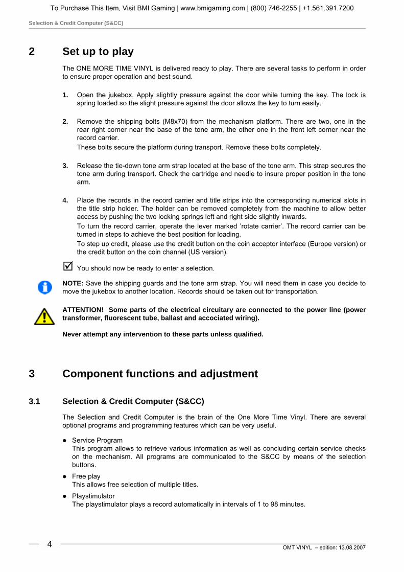
2 Set up to playThe ONE MORE TIME VINYL is delivered ready to play. There are several tasks to perform in orderto ensure proper operation and best sound.
1. Open the jukebox. Apply slightly pressure against the door while turning the key. The lock isspring loaded so the slight pressure against the door allows the key to turn easily.
2. Remove the shipping bolts (M8x70) from the mechanism platform. There are two, one in therear right corner near the base of the tone arm, the other one in the front left corner near therecord carrier.These bolts secure the platform during transport. Remove these bolts completely.
3. Release the tie-down tone arm strap located at the base of the tone arm. This strap secures thetone arm during transport. Check the cartridge and needle to insure proper position in the tonearm.
4. Place the records in the record carrier and title strips into the corresponding numerical slots inthe title strip holder. The holder can be removed completely from the machine to allow betteraccess by pushing the two locking springs left and right side slightly inwards.To turn the record carrier, operate the lever marked ’rotate carrier’. The record carrier can beturned in steps to achieve the best position for loading.To step up credit, please use the credit button on the coin acceptor interface (Europe version) orthe credit button on the coin channel (US version).
" You should now be ready to enter a selection.
NOTE: Save the shipping guards and the tone arm strap. You will need them in case you decide tomove the jukebox to another location. Records should be taken out for transportation.
ATTENTION! Some parts of the electrical circuitary are connected to the power line (powertransformer, fluorescent tube, ballast and accociated wiring).
Never attempt any intervention to these parts unless qualified.
3 Component functions and adjustment
3.1 Selection & Credit Computer (S&CC)
The Selection and Credit Computer is the brain of the One More Time Vinyl. There are severaloptional programs and programming features which can be very useful.
! Service ProgramThis program allows to retrieve various information as well as concluding certain service checkson the mechanism. All programs are communicated to the S&CC by means of the selectionbuttons.
! Free playThis allows free selection of multiple titles.
! PlaystimulatorThe playstimulator plays a record automatically in intervals of 1 to 98 minutes.
To Purchase This Item, Visit BMI Gaming | www.bmigaming.com | (800) 746-2255 | +1.561.391.7200

Service programs
OMT VINYL – edition: 13.08.2007 5
3.2 Service programs
3.2.1 How to call up service program
1. Set slide switch ’SERVICE’ (1) to ’ON’.
2. Press ’LT’ button (2) once.
Button 0 - least popular titles (flops)Pressing button 0 once indicates the leastpopular record. Pressing button 0 againshows the record with second lowest numberof plays. Press button 0 again shows thethird lowest etc..Press button ’R’ (RESET) to terminate the’flop’ call.
Button 1 - Top TunesShows the record which was played most frequently followed by the number of plays (Max. 99). Ifone record was played more often than 99 times, the counter remains in this position. Pressingbutton 1 again shows the second popular record, etc.Press button ’R’ RESET to terminate the ’Top Tune’ call.
Button 2 - cash box contentsShows the cash box contents in basic units; basic units being the value of the lowest coin, resp. coinvalue of coin output 1 on the S&CC.
Example (lowest coin 25ct): display readout: 0 4 5 = 45 x 25ct = $ 11.25
Press button ’R’ RESET to terminate the ’cash box contents’ call.
Button 3 - clear memoryPress and hold down button 3, then press button ’R’ RESET. All counters are reset to zero.
Button 4 - display check and program number versionWhen you press button 4 the digital display automatically indicates the number 8 on all three digits.Successivly ’Record Playing’, ’Hit of the House’, ’Error’ and ’Credit’ will light and the program versionnumber will appear, e.g. 7.01 or higher.
Button 5 - PlaystimulatorThe playstimulator is playing a random record automatically after a programmed time period. It isprogrammable between 1 and 98 minutes. For programming please refer to chapter 3.4, on page 7.
0047971
1245T1
1020T
+B
M LT
MemoryON
ST1ST2
ST3
OFF
Selection &Credit Computer
100 - 160 - 200
K
Z
ONOFF
M3 M6 M C
Service
GP BS B4 B3 B2 B1KorbLocation
0 02
3
4
5
6
2
3
4
5
6
F
2
3
4
5
6
1
0
2
3
4
5
6
1
0
2
3
4
5
6
1
0
7T.T.+2+3
GP+6
ACHTUNG:
ATTENTION:
A :TTENTION
MEMORY-Stecker von OFFauf ON umstecken, wennTop Tunes, Popularitätszähleroder Kassenzähler arbeiten soll.Move MEMORY Plug from OFFto ON if Top tunes, Pop Meter orCash Box Content Registrationis required.Placer la prise MEMORY enposition ON de la position OFFsi le Top Tunes, le compteur depopularité et le contenu de lacaisse sont demandés.
1 2
To Purchase This Item, Visit BMI Gaming | www.bmigaming.com | (800) 746-2255 | +1.561.391.7200

Free play
OMT VINYL – edition: 13.08.20076
Button 6 - A-side solenoidWhen you press button 6 the display shows 6 - 1, relay M6 of the S&CC and the A-side solenoidshould be activated while the display shows 6 - 2.
Button 7 - check of gear box motorWhen you press button 7 relay M should be activated and the changer plays the B-side of the record.Display shows 7 - 4.After the record has been played, it will be returned into the carrier.
Button 8 - check of record carrierWhen you press button 8 relay M3 is activated and the record carrier turns as long as button 8 ispressed. The gripper arm must be in rest position. The display shows 8 - 0.
Button 9 - gripper arm positionPress button 9, test of the gripper arm position. Display shows 9 - 0 if the gripper arm is in restposition, 9 - 1 if the gripper arm is in play position.
3.2.2 How to leave the service program
1. Set slide switch ’SERVICE’ to ’OFF’.
1. Press ’LT’ button. The record carrier turns to position 101.
3.2.3 Memory ON/OFF
ATTENTION! Statistic read outs(service programs 0 - 2) are onlyvalid if the internal memorybattery is connected to MemoryON (plug on upper pin) asshown.With Memory OFF (plug on lowerpin) counters are reset when thejukebox is switched off.
3.3 Free play
Connect jumper wire on ’GP’ between0 and F on the S&CC. Press ’LT’button.
Free play now allows free selections.
0047971
1
2
4
5
T1
10
20T
+B
M LT
MemoryON
ST
1S
T2
ST
3
OFF
Selection &Credit Computer
100 - 160 - 200
K
Z
ONOFF
M3 M6 M C
Service
GP BS B4 B3 B2 B1KorbLocation
0 02
3
4
5
6
2
3
4
5
6
F
2
3
4
5
6
1
0
2
3
4
5
6
1
0
2
3
4
5
6
1
0
7T.T.+2+3
GP+6
ACHTUNG:
ATTENTION:
A :TTENTION
MEMORY-Stecker von OFFauf ON umstecken, wennTop Tunes, Popularitätszähleroder Kassenzähler arbeiten soll.
Move MEMORY Plug from OFFto ON if Top tunes, Pop Meter orCash Box Content Registrationis required.
Placer la prise MEMORY enposition ON de la position OFFsi le Top Tunes, le compteur depopularité et le contenu de lacaisse sont demandés.
M LTON
OFFGP BS B4 B3 B2 B1Korb
Location
0 02
3
4
5
6
2
3
4
5
6
F
2
3
4
5
6
1
0
2
3
4
5
6
1
0
2
3
4
5
6
1
0
7T.T.+2+3
GP+6
To Purchase This Item, Visit BMI Gaming | www.bmigaming.com | (800) 746-2255 | +1.561.391.7200

Playstimulator / continuous play
OMT VINYL – edition: 13.08.2007 7
3.4 Playstimulator / continuous play
The playstimulator may be programmed to random selection of a title in periods of 1 to 98 minutes.(Factory preset is 99 for continuous play). Therefore:
1. Call up service program (slide switch SERVICE in position ON, press ’LT’ button once).
2. Press button 5.
3. Press button 9, display shows 9 _ _.
4. Enter number of minutes required for the interval between play# 01 = 1 minute# 02 = 2 minutes etc.# 00 = playstimulator is switched OFF# 99 = continuous play
5. Press button ’R’ RESET.
6. Set slide switch SERVICE to position OFF.
7. Press ’LT’ button.
NOTE: If the jukebox is equipped witha continuous play switch, you onlyhave to set the slide switch to positionON to activate the playstimulator/continuous play.
Continuous
Play
onoff
0047971
1245T1
1020T
+B
M LT
MemoryON
ST1ST2
ST3
OFF
Selection &Credit Computer
100 - 160 - 200
K
Z
ONOFF
M3 M6 M C
Service
GP BS B4 B3 B2 B1KorbLocation
0 02
3
4
5
6
2
3
4
5
6
F
2
3
4
5
6
1
0
2
3
4
5
6
1
0
2
3
4
5
6
1
0
7T.T.+2+3
GP+6
ACHTUNG:
ATTENTION:
A :TTENTION
MEMORY-Stecker von OFFauf ON umstecken, wennTop Tunes, Popularitätszähleroder Kassenzähler arbeiten soll.Move MEMORY Plug from OFFto ON if Top tunes, Pop Meter orCash Box Content Registrationis required.Placer la prise MEMORY enposition ON de la position OFFsi le Top Tunes, le compteur depopularité et le contenu de lacaisse sont demandés.
To Purchase This Item, Visit BMI Gaming | www.bmigaming.com | (800) 746-2255 | +1.561.391.7200

Coin and credit programming
OMT VINYL – edition: 13.08.20078
3.5 Coin and credit programming
The price per play is set by jumper wires on the S&CC as shown in the examples. After havingchanged wire links press ’LT’ button to confirm new settings.
NRI
G13
1 play for 50 cts3 plays for $ 1.0021 plays for $ 5.00
0,25 blue
1 $ greyorangeyellow
whitebrown
25cts $ 1.00
GP BS B4 B3 B2 B1
TT+2+3
:
::::
::
:
::::
::
:
::::
::
:
::::
::
:
::::
::
:
::::
::
:
::::
::
LT23456
0
F
23456
0
7 1245
T11020
+B^
6543210
6543210
6543210
GP+6
KorbLocation
PRICE OF SELECTION
Select 222 for 8 Top Ten
Coinco
mech.
GP BS B4 B3 B2 B1KorbLocation
GP+6
T.T.+2+3
:
::::
::
:
::::
::
:
::::
::
:
::::
::
:
::::
::
:
::::
::
:
::::
::
LT23456
0
F
23456
0
7 1245
T11020
+B
6543210
6543210
6543210
2 plays - 0,55 plays - 1,-11 plays - 2,-
0,5 1,- 2,- 0,5 red.1,0 brown
grey
greenviolet
2,0 white
T
Credit buttonon interface
US (example)
Europe (example)
To Purchase This Item, Visit BMI Gaming | www.bmigaming.com | (800) 746-2255 | +1.561.391.7200

Coin and credit programming
OMT VINYL – edition: 13.08.2007 9
4 Device description of the amplifier K99The amplifier K99 is optimised for universal use in Deutsche Wurlitzer GmbH jukeboxes. Greatimportance had been attached for an easy handling and stand alone function without the S&CC unit.The output power is designed for the standard used internal speakers of Deutsche Wurlitzer GmbHjukeboxes.
DETAILS:Standard equipment:
! Hybrid power stage technology, short circuit and over temperature protected
! 2 inputs (stereo): CD and tape
! 1 mono input for optional microphone kit
! Volume control with 2 pots onboard
! Volume control possible with pots and / or IR at the same time. The pot used at last determinesthe volume.
! The wired remote box is accessible from the machine rear wall with 2 volume control pots, canceland mute button (mute with toggle function).
! Bass and treble control with pots
! BGM volume reduction, controllable with pot
! Automatic volume correction (AVC), switchable
! 2 channel operation switchable, RH = internal speakers, LH = external speakers
! Status display with 7segment display
! Independent controllable RCA output to connect external amplifiers
! For use with the old and the new changer mechanism.
!
Optional:
! Remote control with large distance range. Functions: track selection / volume chan. 1 / volumechan. 2 / mute (toggle) / cancel
! 70v output transformer
! Microphone kit
5 Technical data K99General USA / Canada
Supply 100v - 240v 117v
Mains frequency 50cps - 60cps 60cps
Input voltage CD typ. 1.2v typ. 1.2v
Input voltage tape 300mv 300mv
Output voltage pre amplifier <=1veff <=1veff
Output power 2 x 55w (rms) 2 x 55w (rms)
Output impedance min. 4ohm min. 4ohm
Transmission range 20cps - 20,000cps 20cps - 20,000cps
Distorsion factor < 1% < 1%
Noise level Depending on the adjusted volume of the jukebox noise levels of more than 70 dB(A) can be reached.
To Purchase This Item, Visit BMI Gaming | www.bmigaming.com | (800) 746-2255 | +1.561.391.7200

Coin and credit programming
OMT VINYL – edition: 13.08.200710
6 Verification of power voltageThe voltage settings are marked onthe cover plate of the mainstransformer. Machines for USA areset to 117v. They have a specialtransformer according to UL standardwhich is not adjustable. Jukeboxes“UNI-Pack” are shipped with 230vsetting. Mains voltage is indicated onthe label of the transformer cover. Themains fuse (T3.15A/230v F6A/117v)is located on the left bottom side in-between the three terminals for the billacceptor, the external mains switchand the fluorescent lamps.
Loosen the four screws to remove thecover plate (small arrows) to getaccess to the mains transformer.
ATTENTION! Always remove power plug before opening transformer cover plate. Neverattempt any intervention to these parts unless qualified!
The position of the two plug connectors on the transformer terminals 1 to 9 (primary side) indicatesthe current voltage setting. The following combinations are possible:
240v = 1 - 9
230v = 1 - 8
220v = 2 - 9
210v = 2 - 8
117v = 1 - 6
100v = 2 - 6
Notice that these settings cannot bemade on machines producedaccording to UL standard (USversion).
NOTE: Never connect the fluorescentsupply to other contact.
If you intend to change the powervoltage to a higher voltage (e.g. from117v to 230v) it is recommended touse a subtransformer for thefluorescent lamps or change theballast according to the used voltage(e.g. for 230v).
NetzsicherungMains Fuse210-240V - T 4A100-117V - F 6A
LeuchtstofflampenFluorescent Lamps
230V / 117V
Vers
tärk
erAm
plifi
er
Externer HauptschalterExternal Mains switch
Schein-annehmerBill-acceptor
AchtungVor A nahme er appe en Netzsteckerziehen
arningShock hazar o not open
ur Beachtung Nur Sicherungen mitgleicher r e un gleichem erterwen en, um Schä en zu ermei en
aution To re uce the risk of firereplace onl with same t p an rating fuses
Netzspannung50/60 Hz
Mains Voltage50/60 cps
240230220210117100
Netzsicherung/Mains Fuse210-240V - T3,15A100-117V - F6A
1 - 8 = 230V
Mains voltage-Netzspannung
240V = 1 - 9230V = 1 - 8
220V = 2 - 9210V = 2 - 8
117V = 1 - 6
100V = 2 - 6
Temperaturwächter
thermalfuse= 2 - 4
Deutsche Wurlitzer GmbHArt.-Nr. 0058498 K99 210VA
VDE 0551/ EN 60742 50/60Hz12
34
56
78
9 1011
1213
1415
1617
18
gy
br
y/r
wt
wt/r
bk
bl
bk
amplifier
mains
fluorescentlamps
To Purchase This Item, Visit BMI Gaming | www.bmigaming.com | (800) 746-2255 | +1.561.391.7200

Coin and credit programming
OMT VINYL – edition: 13.08.2007 11
7 Position of fuses and plug connectors on the K99Fuses used on the amplifier boardare DIN41571 5x20 slow blow ormedium blow in the US version6x32 slow blow.Value of used fuses is printed onthe amplifier cover. Please replaceonly with same type and ratingfuses.
The fuse holders on the amplifierP.C.B. are capable to hold fuses of6x32mm or 5x20mm size.
You will find the fuses behind theamplifier cover plate. To removethe plate first unplug the cablecoming from the mains transformerand cable to the IR remote control.Next lose slightly both nuts on topof the amplifier accessible throughthe holes in the cover plate(arrows). To remove the plate first take the bottom side out of its hinges and then the top side.
Connection plan of the plug terminals:! 1P09 - mechanism, SCC unit! 1P06A - option! 1P06B - RIAA decoder! 2LP04 - external speakers, LH! 2P04 - external speakers, ground! 2RP04 - external speakers, RH! 2P12 - Internal speakers! 1P03 - bubble tubes
Fuse FailureMain fuse T 3.15 resp. F6 A for 110/117 V. No illumination, machine completely dead.
Fuse F1: T4A supply 30V ~ Credit circuit via LED M is interrupted. If credits are still in memory or free play is programmed.
Fuse F2: T4A supply 26V ~Fuse F3: T4A supply 26V ~
The colour tubes of the One More Time do not rotate, the heating of the bubble tubes is off - no bubbles will appear. Possibly defect of the power stage of the amplifier.
Fuse F4: T4A supply +12 V= SCC unit dead - digital display dark (except red LED M still lighting up on coin insertion). The LED’s K and Z on the SCC unit are dark. No initialisations run after power ON. The status display on the amplifier is dark.
CAUTIONTO REDUCETHE RISKOF FIRE REPLACE ONLYWITH SAMETYPE ANDRATING FUSE
Bass Treble BGM
M
S
ONO
TEREO
ANAL HANNEL
TEREO
2-K / 2-C
S
SF
ICHERUNG
USEF1 - F4
100-240V50Hz/60Hz
117 V60Hz
3,0 AMP250 V ACSLOW BLOW
T 4 A
30V~AC
F1
26V~AC
F2
26V~AC
F3
12V=DC
F4
I LNTERNER AUTSPRECHER
NTERNAL PEAKERI S
OP
TIO
N
OP
TIO
N
RL
EL
ES
8/
80
W
XT
ER
NE
RA
UT
SP
RE
CH
ER
XT
ER
NA
LP
EA
KE
R
W
CD-TCD-T
RAFO
RANSFORMER
B -TUBBLE UBES
NT
ETZTRAFO
RANSFORMER
EERWEITERUNG
XTENSIONF
R CERNREGLER
EMOTE- ONTROL
RS
23
2
BG
M
IR
IR
NF
RA
RO
T-E
GL
ER
NF
RA
RE
D-
EM
OT
E
A OL
R
US
GA
NG
UT
PU
T
EC
DI
CD
LR
ING
AN
G
NP
UT
EE
30
0m
VX
TR
A
XT
RAE
30
0m
VI
LR
ING
AN
G
NP
UT
MM
IKR
OF
ON
ICR
OP
HO
NE
MECHANIK
MECHANISM
D AR C
ECKEL BNEHMEN
EMOVE OVER
D AR C
ECKEL BNEHMEN
EMOVE OVER
IC 1
ntern
hannel
EC
xtern
hannel 2
Verstärker K 99 0056041
Amplifier K 99 C-UL 00584841P09
1P06B
2P04
2LP04
2RP04
2P12
1P04
1P03
1P06A
AVC
RS232MICRO
TAPE
MUTE
A / DNZEIGE ISPLAY
BGM
ok.
S / SCHALTER WITCHES
A /OUS FF
A /OUS FF
E /OIN N
E /OIN N
A
A
VC
VC
MODESTEREO 2-K /2CANAL HANNEL
INPUTCD TAPE
BGM
1
1
3
5
2
2
4
6
SEPARATE
NORMAL
AUTO
VOLUME
RS232
MUTE
HIGH LOW
PARALLEL
SERVICE
AUS/OFF
To Purchase This Item, Visit BMI Gaming | www.bmigaming.com | (800) 746-2255 | +1.561.391.7200

Coin and credit programming
OMT VINYL – edition: 13.08.200712
8 The first power ONThe mains switch is located at the rearside of the jukebox. Wallboxes areequipped with an external mainsswitch accessible from the side. Inposition ‘I’ jukebox and amplifier areswitched on.
Up to approx. 1 sec. after power onrandom segments of the status displaywill light. Followed by displaying theversion number of the amplifiersoftware (1.0, or higher). Then thebottom segment for “ok.” and theupper segment for MUTE will light.The amplifier is now in STANDBYMODE. Depending on other enabledoptions more segments may light aswell (e.g. AVC).
9 Volume controlYou can control the volume of thejukebox from different points at thesame time:
! With the pots Channel 1 andChannel 2 on the amplifier.
! With an optional available IRremote control.
! With the pots of the control box atthe rear side of the jukebox.
The device from which the volume ischanged determines it.
The volume control box can be takenout and be used as a remote control.Its cable may be extended as requiredwith any kind of wire. The voltages of the control wires are max. 5v DC.
The control box has two volume knobs (Intern / Channel 1 and Extern / Channel 2). In position”Stereo” the knob “Intern / Channel 1” is effective for the internal speakers. The knob Extern /Channel 2 is controlling the volume of the RCA outputs for an optional external amplifier. In DIPswitch position ”2 Channel”, channel1 (RH) and 2 (LH) are controlled separately.
ATTENTION! The pots Channel 1 and Channel 2 on the amplifier are not effective if the wirecontrol box is connected.
CAUTIONTO REDUCETHE RISKOF FIRE REPLACE ONLYWITH SAMETYPE ANDRATING FUSE Bass Treble BGM
M
S
ONO
TEREO
ANAL HANNEL
TEREO
2-K / 2-C
S
SF
ICHERUNGUSE
F1 - F4
100-240V50Hz/60Hz
117 V60Hz
3,0 AMP250 V ACSLOW BLOW
T 4 A
30V~AC
F1
26V~AC
F2
26V~AC
F3
12V=DC
F4
I LNTERNER AUTSPRECHERNTERNAL PEAKERI S
OP
TIO
N
OP
TIO
N
RL
EL
ES
8/8
0W
XTE
RN
ER
AUTS
PR
EC
HE
RX
TER
NA
LP
EA
KE
RW
CD-TCD-T
RAFORANSFORMER
B -TUBBLE UBES
NT
ETZTRAFORANSFORMER
EERWEITERUNG
XTENSION FR C
ERNREGLEREMOTE- ONTROL
RS
232
BG
M
IR
IR
NFR
ARO
T-E
GLE
RN
FRA
RE
D-
EM
OTE
A OL
R
US
GA
NG
UTP
UT
EC
DI
CD
LR
ING
AN
GN
PU
TE
E30
0mV
XTR
AX
TRAE
300m
VI
LR
ING
AN
GN
PU
TM M
IKRO
FON
ICRO
PH
ON
E
MECHANIKMECHANISM
D AR C
ECKEL BNEHMENEMOVE OVER
D AR C
ECKEL BNEHMENEMOVE OVER
S / SCHALTER WITCHES
A /OUS FF
A /OUS FF
E /OIN N
E /OIN N
AVCMODESTEREO 2-K /2CANAL HANNEL
INPUTCD TAPE
BGM
1
1
3
5
2
2
4
6
IC 1
nternhannel
EC
xternhannel 2
Verstärker K 99 0056041Amplifier K 99 C-UL 0058484
A / DNZEIGE ISPLAY
AVCRS232
MICRO
TAPE
MUTE
BGMok.
AVCS232MICRO
TAPE
MUTE
BGMok.
CAUTIONTO REDUCETHE RISKOF FIRE REPLACE ONLYWITH SAMETYPE ANDRATING FUSE
Bass Treble BGM
M
S
ONO
TEREO
ANAL HANNEL
TEREO
2-K / 2-C
S
SF
ICHERUNG
USEF1 - F4
100-240V50Hz/60Hz
117 V60Hz
3,0 AMP250 V ACSLOW BLOW
T 4 A
30V~AC
F1
26V~AC
F2
26V~AC
F3
12V=DC
F4
I LNTERNER AUTSPRECHER
NTERNAL PEAKERI S
OP
TIO
N
OP
TIO
N
RL
EL
ES
8/
80
W
XT
ER
NE
RA
UT
SP
RE
CH
ER
XT
ER
NA
LP
EA
KE
R
W
CD-TCD-T
RAFO
RANSFORMER
B -TUBBLE UBES
NT
ETZTRAFO
RANSFORMER
EERWEITERUNG
XTENSIONF
R CERNREGLER
EMOTE- ONTROL
RS
23
2
BG
M
IR
IR
NF
RA
RO
T-E
GLE
R
NF
RA
RE
D-
EM
OT
E
A OL
R
US
GA
NG
UT
PU
T
EC
DI
CD
LR
ING
AN
G
NP
UT
EE
30
0m
VX
TR
A
XT
RAE
30
0m
VI
LR
ING
AN
G
NP
UT
MM
IKR
OF
ON
ICR
OP
HO
NE
MECHANIK
MECHANISM
D AR C
ECKEL BNEHMEN
EMOVE OVER
D AR C
ECKEL BNEHMEN
EMOVE OVER
IC 1
ntern
hannel
EC 2
xtern
hannel
Verstärker K 99
Amplifier K 99 C-UL
AVC
RS232MICRO
TAPE
MUTE
A / DNZEIGE ISPLAY
BGM
ok.
S / SCHALTER WITCHES
A /OUS FF
A /OUS FF
E /OIN N
E /OIN N
A
A
VC
VC
MODESTEREO 2-K /2CANAL HANNEL
INPUTCD TAPE
BGM
1
1
3
5
2
2
4
6
SEPARATE
NORMAL
AUTO
VOLUME
RS232
MUTE
HIGH LOW
PARALLEL
SERVICE
AUS/OFF
To Purchase This Item, Visit BMI Gaming | www.bmigaming.com | (800) 746-2255 | +1.561.391.7200

Coin and credit programming
OMT VINYL – edition: 13.08.2007 13
10 The infrared remote controlAn infrared remote control is installed from factoryor can be delivered as conversion kit (part no.0058809). If it has been installed the handtransmitter is located in the cash box.
If credit is given or free play is programmed arecord can be selected with the buttons 0 to 9 andR.
Double button functions as required in the serviceprograms (i.e. press button 5 -hold down- andpress button R), are impossible. For this you canonly use the keyboard of the jukebox.
You can control the volume by means of thebuttons + and -. In stereo mode the internal +/-buttons control the volume of the internal speakers.The external +/- buttons control the volume of theK99 RCA jacks for an optional external amplifier. In2-channel mode these buttons control the volumeof the external speakers connected to the amplifier.
The power-on volume level is always set by thechannel 1 and 2 pots on the amplifier or on theexternal volume control box.
Batteries are included: 4 micro cells type LR03(AAA).
To open the battery compartment move the coverlike shown in the picture.
Type and position of the batteries are also shownin the drawing.
Part no. of the hand transmitter: 0059745.
RCS-K
No.: 0059745
SELECTION
1 2 3
4 5 6 RESET
POWER
OPTION
7 8 9
0
- +
- +
BATTERY:
IEC LR03(AAA)
+
+
+
+
CANCEL MUTE
VOLUME
INTERNCHANNEL 1
EXTERNCHANNEL 2
selection buttons
music control buttons
battery type LR03 (AAA)
position ofthe batteries
To Purchase This Item, Visit BMI Gaming | www.bmigaming.com | (800) 746-2255 | +1.561.391.7200

Coin and credit programming
OMT VINYL – edition: 13.08.200714
11 Treble and bass controlSound control can be made by the bass andtreble pots on the amplifier.
12 Automatic volume correctionThe AVC sets records with different volume levels to anequal level. The level of records with a high level will bereduced; the level of low-levelled records will beincreased. This control works rather slow to save thedynamic range of the track.
You can enable the correction with the DIP switch “AVC”(the 3rd switch of the 6 sw. group) on the amplifier board.Factory preset is AVC disabled.
With the second DIP switch of the 6 sw. group you canreduce the intensity of volume correction.
13 Background Music - volume attenuationComplete function is only available for CD models.
You can switch on “BGM” by means of the DIP switch“BGM”. The RH bottom segment of the status display onthe amplifier indicates “BGM active”. You can adjust thevolume attenuation with the pot “BGM”, as long it isactive.
This function can be used to limit the maximum outputvolume.
CAUTIONTO REDUCETHE RISKOF FIRE REPLACE ONLYWITH SAMETYPE ANDRATING FUSE
Bass Treble BGM
M
S
ONO
TEREO
ANAL HANNEL
TEREO
2-K / 2-C
S
SF
ICHERUNG
USEF1 - F4
100-240V50Hz/60Hz
117 V60Hz
3,0 AMP250 V ACSLOW BLOW
T 4 A
30V~AC
F1
26V~AC
F2
26V~AC
F3
12V=DC
F4
I LNTERNER AUTSPRECHER
NTERNAL PEAKERI S
OP
TIO
N
OP
TIO
N
RL
EL
ES
8/
80
W
XT
ER
NE
RA
UT
SP
RE
CH
ER
XT
ER
NA
LP
EA
KE
R
W
CD-TCD-T
RAFO
RANSFORMER
B -TUBBLE UBES
NT
ETZTRAFO
RANSFORMER
FR C
ERNREGLER
EMOTE- ONTROL
RS
23
2
BG
M
IR
IR
NF
RA
RO
T-E
GLE
R
NF
RA
RE
D-
EM
OT
E
A OL
R
US
GA
NG
UT
PU
T
EC
DI
CD
LR
ING
AN
G
NP
UT
EE
30
0m
VX
TR
A
XT
RAE
30
0m
VI
LR
ING
AN
G
NP
UT
MM
IKR
OF
ON
ICR
OP
HO
NE
MECHANIK
MECHANISM
D AR C
ECKEL BNEHMEN
EMOVE OVER
D AR C
ECKEL BNEHMEN
EMOVE OVER
IC 1
ntern
hannel
EC 2
xtern
hannel
Verstärker K 99
Amplifier K 99 C-UL
AVC
RS232MICRO
TAPE
MUTE
A / DNZEIGE ISPLAY
BGM
ok.
S / SCHALTER WITCHES
A /OUS FF
A /OUS FF
E /OIN N
E /OIN N
A
A
VC
VC
MODESTEREO 2-K /2CANAL HANNEL
INPUTCD TAPE
BGM
1
1
3
5
2
2
4
6
SEPARATE
NORMAL
AUTO
VOLUME
RS232
MUTE
HIGH LOW
PARALLEL
SERVICE
AUS/OFF
ERWEITERUNG
EERWEITERUNG
XTENSION
Bass Treble BGM
FR C
ERNREGLEREMOTE- ONTROL
RS
232
IR
IR
NF
RA
RO
T-E
GLE
RN
FR
AR
ED
-E
MO
TE
IC 1
ntern
hannel
EC
xtern
hannel 2
AVC
RS232MICRO
TAPE
MUTE
A / DNZEIGE ISPLAY
BGM
ok.
S / SCHALTER WITCHES
A /OUS FF
A /OUS FF
E /OIN N
E /OIN N
A
A
VC
VC
MODESTEREO 2-K /2CANAL HANNEL
INPUTCD TAPE
BGM
1
1
3
5
2
2
4
6
SEPARATE
NORMAL
AUTO
VOLUME
RS232
MUTE
HIGH LOW
PARALLEL
SERVICE
AUS/OFF
EERWEITERUNG
XTENSION
Bass Treble BGM
EERWEITERUNG
XTENSIONF
R CERNREGLER
EMOTE- ONTROL
RS
232
IR
IR
NF
RA
RO
T-E
GLE
RN
FR
AR
ED
-E
MO
TE
IC 1
ntern
hannel
EC
xtern
hannel 2
AVC
RS232MICRO
TAPE
MUTE
A / DNZEIGE ISPLAY
BGM
ok.
S / SCHALTER WITCHES
A /OUS FF
A /OUS FF
E /OIN N
E /OIN N
A
A
VC
VC
MODESTEREO 2-K /2CANAL HANNEL
INPUTCD TAPE
BGM
1
1
3
5
2
2
4
6
SEPARATE
NORMAL
AUTO
VOLUME
RS232
MUTE
HIGH LOW
PARALLEL
SERVICE
AUS/OFF
To Purchase This Item, Visit BMI Gaming | www.bmigaming.com | (800) 746-2255 | +1.561.391.7200

Coin and credit programming
OMT VINYL – edition: 13.08.2007 15
14 External speaker connectionThe amplifier can operate in twodifferent modes. The normal operationmode reproduces the music in normalstereo sound. So external speakerscan be added to each channel.
The so-called 2-Channel mode usesboth stereo channels like separatemono amplifiers so that the sound canbe reproduced in different rooms butthen in mono only.
The amplifier may not be loaded withmore than 4 ohms per channel (lessohms means more load!). On anoverload it switches itself off. After acertain cool down time it switchesitself on. So if you do not eliminate thereason for the overload the amplifierproduces continuously volume drop-outs.
The impedance of all external speakers per channel in ”Stereo” mode should not be less than 8ohms, because the internal speakers represent a load of already 8 ohms per channel. If the amplifieris operating in 2-Channel mode, the internal speakers are all connected to the RH channel (Channel1); the LH channel (Channel 2) now applying to the screw terminals ”Externer Lautsprecher -External speakers” may be loaded with max. 4 ohms.
The output power of the amplifier is approx. 55 watts (rms on max. 1% dist.) on a 4 ohms speakerper channel, 18 watts to a 12 ohms speaker and approx. 9 watts to a 24 ohms speaker. That means,that e.g., a 12 ohms speaker connected to the external channel at Dual Channel operation must be atype of at least 18 Watts, otherwise the speaker is in danger of destruction at higher volumes. Notethat speaker groups like in hi-fi boxes may have, at certain frequencies, impedance much lower thantheir rating. Make sure that all speakers are connected in correct polarity.
Position of the Stereo - Mono DIP switch (1), themode switch (2), the stereo - 2 channel switch (3)and external speaker terminals (4).
CAUTIONTO REDUCETHE RISKOF FIRE REPLACE ONLYWITH SAMETYPE ANDRATING FUSE
Bass Treble BGM
M
S
ONO
TEREO
ANAL HANNEL
TEREO
2-K / 2-C
S
SF
ICHERUNG
USEF1 - F4
100-240V50Hz/60Hz
117 V60Hz
3,0 AMP250 V ACSLOW BLOW
T 4 A
30V~AC
F1
26V~AC
F2
26V~AC
F3
12V=DC
F4
I LNTERNER AUTSPRECHER
NTERNAL PEAKERI S
O O
PT
ION
PT
ION
RL
EL
ES
8/
80
W
XT
ER
NE
RA
UT
SP
RE
CH
ER
XT
ER
NA
LP
EA
KE
R
W
CD-TCD-T
RAFO
RANSFORMER
B -TUBBLE UBES
NT
ETZTRAFO
RANSFORMER
EERWEITERUNG
XTENSIONF
R CERNREGLER
EMOTE- ONTROL
RS
23
2
BG
M
IR
IR
NF
RA
RO
T-E
GLE
R
NF
RA
RE
D-
EM
OT
E
A OL
R
US
GA
NG
UT
PU
T
EC
DI
CD
LR
ING
AN
G
NP
UT
EE
30
0m
VX
TR
A
XT
RAE
30
0m
VI
LR
ING
AN
G
NP
UT
MM
IKR
OF
ON
ICR
OP
HO
NE
MM
ECHANIK
ECHANISM
D AR C
ECKEL BNEHMEN
EMOVE OVER
D AR C
ECKEL BNEHMEN
EMOVE OVER
AVC
RS232MICRO
TAPE
MUTE
A / DNZEIGE ISPLAY
BGM
ok.
S / SCHALTER WITCHES
A /OUS FF
A /OUS FF
E /OIN N
E /OIN N
A
A
VC
VC
MODESTEREO 2-K /2CANAL HANNEL
INPUTCD TAPE
BGM
1
1
3
5
2
2
4
6
IC 1
ntern
hannel
EC
xtern
hannel2
Verstärker K 99 0056041
Amplifier K 99 C-UL 0058484
1
3
4
2
SEPARATE
NORMAL
AUTO
VOLUME
RS232
MUTE
HIGH LOW
PARALLEL
SERVICE
AUS/OFF
To Purchase This Item, Visit BMI Gaming | www.bmigaming.com | (800) 746-2255 | +1.561.391.7200

Coin and credit programming
OMT VINYL – edition: 13.08.200716
NOTE: Connect external speakers to the screw terminals on the LH amplifier in 2-Channel modeonly!
15 External amplifier connectionThe RCA terminals “Ausgang -Output” can be connected to a lineinput of an external amplifier. InStereo mode the output level isnormally controlled by means of thepot for the 2nd channel. Alternativelyyou can set the first DIP switch (1) toON to couple this output to the normalvolume control knobs (1st channel), sothat both amplifiers can be controlledtogether.
Connecting an external amplifier in 2-channel mode is not useful.
To avoid hum- (earth-) loops try to usean external amplifier with ground lift; it has no earth contacts. If it is impossible (e.g. receivers withcable supply) you can separate both amps by means of the ground isolator part no. 0053300.
The signal of the RCA terminals is also controlled by the settings of bass, treble, BGM, AVC andMute.
NetzsicherungMains Fuse210-240V - T 4A100-117V - F 6A
LeuchtstofflampenFluorescent Lamps
230V / 117V
Vers
tärk
erA
mpl
ifier
Externer HauptschalterExternal Mains switch
Schein-annehmerBill-acceptor
Achtung!Vor Abnahme der Kappe den Netzsteckerziehen!
Warning!Shock hazard! Do not open!
Zur Beachtung: Nur Sicherungen mitgleicher Größe und gleichem Wertverwenden, um Schäden zu vermeiden.
Caution: To reduce the risk of firereplace only with same typ and rating fuses.
Netzspannung50/60 Hz
Mains Voltage50/60 cps
240230220210117100
CAUTIONTO REDUCETHE RISKOF FIRE REPLACE ONLYWITH SAMETYPE ANDRATING FUSE Bass Treble BGM
M
S
ONO
TEREO
ANAL HANNEL
TEREO
2-K / 2-C
S
SF
ICHERUNGUSE
F1 - F4
100-240V50Hz/60Hz
117 V60Hz
3,0 AMP250 V ACSLOW BLOW
T 4 A
30V~AC
F1
26V~AC
F2
26V~AC
F3
12V=DC
F4
I LNTERNER AUTSPRECHERNTERNAL PEAKERI S
OP
TIO
N
OP
TIO
N
RL
EL
ES
8/8
0W
XTE
RN
ER
AUTS
PR
EC
HE
RX
TER
NA
LP
EA
KE
RW
CD-TCD-T
RAFORANSFORMER
B -TUBBLE UBES
NT
ETZTRAFORANSFORMER
EERWEITERUNG
XTENSION FR C
ERNREGLEREMOTE- ONTROL
RS
232
BG
M
IR
IR
NFR
ARO
T-E
GLE
RN
FRA
RE
D-
EM
OTE
A OL
R
US
GA
NG
UTP
UT
EC
DI
CD
LR
ING
AN
GN
PU
TE
E30
0mV
XTR
AX
TRAE
300m
VI
LR
ING
AN
GN
PU
TM M
IKRO
FON
ICRO
PH
ON
E
MECHANIKMECHANISM
D AR C
ECKEL BNEHMENEMOVE OVER
D AR C
ECKEL BNEHMENEMOVE OVER
AVCRS232
MICRO
TAPE
MUTE
A / DNZEIGE ISPLAY
BGMok.
S / SCHALTER WITCHES
A /OUS FF
A /OUS FF
E /OIN N
E /OIN N
AVCMODESTEREO 2-K /2CANAL HANNEL
INPUTCD TAPE
BGM
1
1
3
5
2
2
4
6
IC 1
nternhannel
EC
xternhannel 2
Verstärker K 99 0056041Amplifier K 99 C-UL 0058484
NetzsicherungMains Fuse210-240V - T 4A100-117V - F 6A
LeuchtstofflampenFluorescent Lamps
230V / 117V
Vers
tärk
erA
mpl
ifier
Externer HauptschalterExternal Mains switch
Schein-annehmerBill-acceptor
Achtung!Vor Abnahme der Kappe den Netzsteckerziehen!
Warning!Shock hazard! Do not open!
Zur Beachtung: Nur Sicherungen mitgleicher Größe und gleichem Wertverwenden, um Schäden zu vermeiden.
Caution: To reduce the risk of firereplace only with same typ and rating fuses.
Netzspannung50/60 Hz
Mains Voltage50/60 cps
240230220210117100
CAUTIONTO REDUCETHE RISKOF FIRE REPLACE ONLYWITH SAMETYPE ANDRATING FUSE Bass Treble BGM
M
S
ONO
TEREO
ANAL HANNEL
TEREO
2-K / 2-C
S
SF
ICHERUNGUSE
F1 - F4
100-240V50Hz/60Hz
117 V60Hz
3,0 AMP250V ACSLOW BLOW
T 4 A
30V~AC
F1
26V~AC
F2
26V~AC
F3
12V=DC
F4
I LNTERNER AUTSPRECHERNTERNAL PEAKERI S
OP
TIO
N
OP
TIO
N
RL
EL
ES
8/8
0W
XTE
RN
ER
AUTS
PR
EC
HE
RX
TER
NA
LP
EA
KE
RW
CD-TCD-T
RAFORANSFORMER
B -TUBBLE UBES
NT
ETZTRAFORANSFORMER
EERWEITERUNG
XTENSIONF
R CERNREGLER
EMOTE- ONTROL
RS
232
BG
M
IR
IR
NFR
ARO
T-E
GLE
RN
FRA
RE
D-
EM
OTE
A OL
R
US
GA
NG
UTP
UT
EC
DI
CD
LR
ING
AN
GN
PU
TE
E30
0mV
XTR
AX
TRAE
300m
VI
LR
ING
AN
GN
PU
TM M
IKR
OFO
NIC
ROP
HO
NE
MECHANIKMECHANISM
D AR C
ECKEL BNEHMENEMOVE OVER
D AR C
ECKEL BNEHMENEMOVE OVER
AVCRS232
MICRO
TAPE
MUTE
A / DNZEIGE ISPLAY
BGMok.
S / SCHALTER WITCHES
A /OUS FF
A /OUS FF
E /OIN N
E /OIN N
AVCMODESTEREO 2-K /2CANAL HANNEL
INPUTCD TAPEBGM
1
1
3
5
2
2
4
6
IC 1
nternhannel
EC
xternhannel 2
Verstärker K 99 0056041Amplifier K 99 C-UL 0058484
+
+
+
++
+
+
+++
In Stereo mode do not connect a singlespeaker with less than 8ohm to eachchannel.
Two speakers of 4ohm (serie) alsorepresent total impedance of 8ohm.
8Ω 8Ω 4Ω 4Ω
4Ω4Ω
CAUTIONTO REDUCETHE RISKOF FIRE REPLACE ONLYWITH SAMETYPE ANDRATING FUSE
Bass Treble BGM
M
S
ONO
TEREO
ANAL HANNEL
TEREO
2-K / 2-C
S
SF
ICHERUNG
USEF1 - F4
100-240V50Hz/60Hz
117 V60Hz
3,0 AMP250 V ACSLOW BLOW
T 4 A
30V~AC
F1
26V~AC
F2
26V~AC
F3
12V=DC
F4
I LNTERNER AUTSPRECHER
NTERNAL PEAKERI S
O O
PT
ION
PT
ION
RL
EL
ES
8/
80
W
XT
ER
NE
RA
UT
SP
RE
CH
ER
XT
ER
NA
LP
EA
KE
R
W
CD-TCD-T
RAFO
RANSFORMER
B -TUBBLE UBES
NT
ETZTRAFO
RANSFORMER
FR C
ERNREGLER
EMOTE- ONTROL
RS
23
2
BG
M
IR
IR
NF
RA
RO
T-E
GLE
R
NF
RA
RE
D-
EM
OT
E
A OL
R
US
GA
NG
UT
PU
T
EC
DI
CD
LR
ING
AN
G
NP
UT
EE
30
0m
VX
TR
A
XT
RAE
30
0m
VI
LR
ING
AN
G
NP
UT
MM
IKR
OF
ON
ICR
OP
HO
NE
MM
ECHANIK
ECHANISM
D AR C
ECKEL BNEHMEN
EMOVE OVER
D AR C
ECKEL BNEHMEN
EMOVE OVER
IC 1
ntern
hannel
EC
xtern
hannel2
Verstärker K 99 0056041
Amplifier K 99 C-UL 0058484
AVC
RS232MICRO
TAPE
MUTE
A / DNZEIGE ISPLAY
BGM
ok.
S / SCHALTER WITCHES
A /OUS FF
A /OUS FF
E /OIN N
E /OIN N
A
A
VC
VC
MODESTEREO 2-K /2CANAL HANNEL
INPUTCD TAPE
BGM
1
1
3
5
2
2
4
6
SEPARATE
NORMAL
AUTO
VOLUME
RS232
MUTE
HIGH LOW
PARALLEL
SERVICE
AUS/OFF
EERWEITERUNG
XTENSION
To Purchase This Item, Visit BMI Gaming | www.bmigaming.com | (800) 746-2255 | +1.561.391.7200

Coin and credit programming
OMT VINYL – edition: 13.08.2007 17
16 Disabling the internal mute circuitWith the optional BGM-Connector (partno. 0048130) you can connect anexternal source to the jukebox withautomatic switch over. In this case theamplifier should not be muted duringstandby of the jukebox.
To reach this disable the internal mutecircuit by setting the first DIP switch (1)“Mute” to OFF.
For more information about the BGMconnector please order the DeutscheWurlitzer GmbH technical informationleaflets TI-MA-116.
17 Input selectorWith DIP switch (1) you can set either CDor tape input as active.
AVC
RS232MICRO
TAPE
MUTE
A / DNZEIGE ISPLAY
BGM
ok.
S / SCHALTER WITCHES
A /OUS FF
A /OUS FF
E /OIN N
E /OIN N
A
A
VC
VC
MODESTEREO 2-K /2CANAL HANNEL
INPUTCD TAPE
BGM
1
1
3
5
2
2
4
6
SEPARATE
NORMAL
AUTO
VOLUME
RS232
MUTE
HIGH LOW
PARALLEL
SERVICE
AUS/OFF
ERWEITERUNG
AVC
RS232MICRO
TAPE
MUTE
A / DNZEIGE ISPLAY
BGM
ok.
S / SCHALTER WITCHES
A /OUS FF
A /OUS FF
E /OIN N
E /OIN N
A
A
VC
VC
MODESTEREO 2-K /2CANAL HANNEL
INPUTCD TAPE
BGM
1
1
3
5
2
2
4
6
SEPARATE
NORMAL
AUTO
VOLUME
RS232
MUTE
HIGH LOW
PARALLEL
SERVICE
AUS/OFF
EERWEITERUNG
XTENSION
To Purchase This Item, Visit BMI Gaming | www.bmigaming.com | (800) 746-2255 | +1.561.391.7200

Failures of the illumination, lamps and power system generally
OMT VINYL – edition: 13.08.200718
18 Trouble shooting chart
18.1 Failures of the illumination, lamps and power system generally
Symptom Cause Possible faults! No light, jukebox not working
at all! No power at wall socket! Open primary circuit
! House fuse blown. ! Mains switch off or defective.! Fuse of the jukebox Si1 blown, refer to
chapter 18.2, on page 19! Defective power cord or plug
! Fluorescent tubes do not light, jukebox working
! defective circuit, refer to chapter 18.9.1, on page 25
! Lamps circuit plug not in light socket at amplifier
! Tube not properly seated in holder! Defective starter, defective tube
! One or more of the lights of the display do not light up, jukebox working
! Lamps’ circuit open ! Bulb defective! Defective lamp socket! Defective plug BROWN or its wiring
resp.! Defect inside the S&CC, e.g. lamp
driver transistor
! All lights of the display are dark, jukebox working
! Supply or common return of lamps’ circuit open
! Plug to the digital lights! Wire +30v broken (plug BROWN, pole
6, white line)! External short in lamps circuit has
tripped T5 (inside S&CC), this disables IC14 to protect lamp driver transistors
! Lamps of too high current rating! No 30VAC S&CC supply via pole 1,
plug RED, 30v rectifier D7 defective (this, however, disables the coin acceptance also)
! Digital display remains dark, jukebox working
! Display signal circuit interrupted
! 14-pole D.I.L. plug not in place or wrong way round
! Digital display shows nonsens figures
! Signal lines interchanged ! 14-pole D.I.L. plug to display displaced not in line with base
! S&CC defective, e.g. IC23
! Digital display shows incomplete figures (missing segment)The fault is the same with all three digits.
! Signal for one (or more) segments missing
! One (or more) of 14-pole plug(s) broken off
! One (or more) wire(s) of flat cable broken
! Broken connection at display PC-board! S&CC defective, e.g. IC23
! Digital display shows incomplete figures (missing segment)The fault, however, occurs with one of the three digits only
! Segment signal does not reach this digit
! Cracked conductor on display PC-board! Defective display unit (3 identical one-
digit units)
! One of the digits of the display completely off
! Multiplex signal missing ! Defective plug to display or broken wire (A1, A2, A3)
! S&CC defective (T6, T7, T8)! Defective display element
To Purchase This Item, Visit BMI Gaming | www.bmigaming.com | (800) 746-2255 | +1.561.391.7200

Fuses of the power supply - which one controls what circuit
OMT VINYL – edition: 13.08.2007 19
18.2 Fuses of the power supply - which one controls what circuit
The fuse holders on all boards are captable to hold either 5x20mm fuses of DIN41571 standard orfuses of 6x32mm size.
The mains fuse holder will hold either 5x20 or 6x32mm fuse depending on the screw cap used.
ATTENTION! Please replace fuses only with same type and rating!
Symptoms, if blown! Mains fuse ! (in-screw cap holder in chassis
pan apron) T 3.15 (F6.3 in U.S. version)
! No illumination, jukebox completely dead
! Fuse F2 or F3 ! 30v negative supply ! Amplifier distorting on both channels, green LED 1 not lit
! With the changer, solenoid M3 (carrier latch) and M6 (a-side) not working
! Fuse F2 or F3 ! 30v positive supply ! Amplifier silent! Gear motor not working
! Fuse F4 ! 12v positive supply ! S&CC dead (except red LED-M still lighting up on coin insertion)
! Fuse F1 ! 30v AC supply ! Record carrier motor and turntable motor PM both not working
! S&CC not registering coins (red LED-M not lighting up)
! Fuses on interface front door ! 25v AC supply ! Both rotating cylinders not turning, bubble tubes not heating, lamp in grill not lighting
To Purchase This Item, Visit BMI Gaming | www.bmigaming.com | (800) 746-2255 | +1.561.391.7200

Faults with the coin and credit system
OMT VINYL – edition: 13.08.200720
18.3 Faults with the coin and credit system
The jukebox, however, normally operates with credits established with the Free Credit button(located above the coin switches) resp. on the coin acceptor interface or by inserting coins.
The function of the coin system can be checked by observing the LED ’M’ at the S&CC, whichshould light up with every coin accepted as well as every time Free Credit button is actuated.
Symptom Cause Possible faults! All coins are rejected ! Disabled coin acceptor ! Missing power supply (green LED on
interface is OFF)! Dirt, oil, an odd article in the rejector,
rejector maladjusted or defective! Binding reject rod assembly holding
rejector gate open! Rejector or entire jukebox not leveled
! Wrong credits (or none) with one type of coin
! Coin actuates the wrong coin switch (US version)
! Coin pulse does not reach the S&CC
! Slug rejector not properly positioned, leading the coin into the wrong switch paddle or bypassing it (US version)
! One line of the Coin-Switches-to-S&CC cable broken, disconnected at either end or wrongly set at S&CC connector
! S&CC defective (IC17 - IC19, diodes D14 - D24)
! Permanent credit, display shows 01 permanently, free selections
! Jumper is set from 0 to F (free play)
! Play prices not according to installed label
! Programming mistake ! Wire jumper not in right position, refer to the examples
! Programming jumper making poor contact (such can change pricing only after the unit had been switched off or the ’LT’ button had been actuated
! No credit although coins are properly accepted
! Free play, with GP jumper 0-F still possible
! All coin input lines disabled (LED does not light up)
! Connect coin input lines to S&CC according to credit programming see chapt. 3.5 on page 8.
! S&CC defective (e.g. diode 1 interrupted)
! No credit although coins are registered (LED-M lights up)
! Even no free play credit with GP jumper set 0 to F
! S&CC out of operation ! No power supplied to the S&CC, check fuse F4, see also chapter 18.2, on page 19
! S&CC defective
To Purchase This Item, Visit BMI Gaming | www.bmigaming.com | (800) 746-2255 | +1.561.391.7200

Faults with the selection system (Credit system is working)
OMT VINYL – edition: 13.08.2007 21
18.4 Faults with the selection system (Credit system is working)
Symptom Cause Possible faults! No selections, number of
actuated keys not displayed (credits available)
! Open or shorted circuits in the keyboard wiring
! Plug YELLOW displaced or not deep enough inserted
! Key RESET permanently closed or shortened to ground (pole 12, brown, plug YELLOW)
! No selections. After insertion of coins a number appears in the LH (hundreds) digit, but selection keys are disabled. With insertion of further coins credits are displayed properly.
! Permanent signal from the selection key which number appears in the dsiplay
! Jammed key, permanently closed key contact
! Wire of this key shortened to ground
! No response from one (or more) key(s)
! Open circuit with this key(s) ! Malfunction of the key contact! Broken wire to keyboard! Plug YELLOW not correctly seated! S&CC defective
! The record played is not the one selected. The selection was properly displayed, and the ’RECORD PLAYING’ display is the same
! Improper counting of the record carriers’ position
! Wrong adjustment of light control gates (refer to chapter 18.9.3 and chapter 18.9.4, on page 26)
! Interference pulses counted as carrier pulses
! Illumination light affecting the Z light gate, reflections at the edges of carrier base plate
! The record played is not the one selected. The selection was properly displayed, and the ’RECORD PLAYING’ display is showing the actually playing record
! Record carrier does not stop in the correct porsition
! Record carrier latch delayed by mechanical friction
! Record carrier latch too wide (latching to late)
! Light control gate Z retarded, refer to chapter 18.9.3 and chapter 18.9.4, on page 26 for proper adjustment
! The selected record will not be played. Instead the record carrier rotates contiuously, however, it stops if ’BLUE’ plug is pulled at the S&CC
! Light gate signal Z (counting) or K (carrier position 1) or both missing
! Lamp of light gate defective! Broken line in the wire to plug BLACK! See notes of chapter 18.9.3 and
chapter 18.9.4, on page 26
To Purchase This Item, Visit BMI Gaming | www.bmigaming.com | (800) 746-2255 | +1.561.391.7200

Repetitive play of records, selected or non-selected ones
OMT VINYL – edition: 13.08.200722
18.5 Repetitive play of records, selected or non-selected ones
18.6 Failures of the record changer after properly completed selection
Symptom Cause Possible faults! Repetitive play of one record
with the record carrier not making a rotation between plays. This continues even if ’BLUE’ plug is disconnected at the S&CC.
! Main cam motor not stopping at the end of the play cycle
! Braking resistor R10 (47ohms) at motor MM open
! Wiper switch K6 maladjusted
! Repetitive play of one record, discontinued after plug ’BLUE’ is pulled at the S&CC
! S&CC running out of program ! S&CC out of program routine, possibly caused by an interference pulse (cut power to the S&CC for a restart of program)
! S&CC defective
! Gripper moves a record continuously (without having the record actually played)
! Motor MM has a permanent ground return
! Line blue to pole 2 of plug ’BLUE’ shorted to ground
! Wiper K6 shorted to ground! S&CC defective (Relay 2-M-
permanently on, pull plug ’BLUE’ to test this. Try service program, button 7 and observe relay 2 through hole M)
Symptom Cause Possible faults! Record carrier continuously
rotating, even after plug ’BLUE’ is pulled.
! If a selection is made the carrier will be jammed when the gripper arm tries to grip a record
! Stop pawl arm permanently open
! Carrier latch or its solenoid jammed
! Record carrier continuously rotating
! If a selection is made the record played is one placed about 10 compartments behind the selected one
! Stop pawl arm solenoid permanently switched on
! Grey line from M3 to pole 4 of plug ’BLUE’ shorted to ground (= fault does persist if plug ’BLUE’ is pulled)
! Relay 4 of the S&CC jammed or permanently switched on (= carrier stops as soon as plug ’BLUE’ is pulled)
! Carrier does not start after a properly completed selection
! Stop pawl arm does not open
! Stop pawl arm not activated ! DC supply -30v missing (fuse F2 or F3)! Coil of latch solenoid M3 open! Grey line from M3 to pole 4 or green
line to pole 1 (relays common), plug ’BLUE’ interrupted
! S&CC defective. Go to service program, key 8, to check relay 2 -M3-. Test machine with a programming jumper from pole 1 (green) to pole 4 (grey) (refer to chapter 18.9.12, on page 27)
To Purchase This Item, Visit BMI Gaming | www.bmigaming.com | (800) 746-2255 | +1.561.391.7200

Failures of the record changer after properly completed selection
OMT VINYL – edition: 13.08.2007 23
! Record carrier does not rotate although the carrier latch opens after a selection
! Carrier motor KM disabled ! Microswitch M3 (at carrier latch) maladjusted or defective)
! Microswitch K8 (at gripper arm) maladjusted or gripper arm not full in rest position (refer to chapter 18.9.6, on page 26)
! Defective motor KM, broken wiring
! A-side selections (odd numbers) are not played but the B-side of selected record is played instead
! M6 shift solenoid and/or shift rod not working
! M6 coil open, M6 circuit open (refer to chapter 18.9.7, on page 26)
! Pole 3 (violet wire) of plug ’BLUE’ not making contact. To check this, plull plug ’BLUE’ and insert a jumper wire (programming jumper of the S&CC) from pole 1 (green) to pole 3 (violet). If M6 is energized now, the fault is inside the S&CC (e.g. relay 3 -M6- is not working)
! Gripper arm does not move to take the record out of the carrier although the carrier has stopped at the correct position. After approx. 3 seconds the carrier moves to the next selection if further selections have been made
! Main cam motor MM does not start
! Motor MM defective, resistor R15 (18ohms) open, no DC +30v to the motor (fuse Si4), interruption with the blue line from amplifier to motor
! Short within the motor or with capacitor C5 (in these cases R15 gets rather hot!) Pull plug ’BLUE’ and set a jumper from pole 1 (green) to pole 2 (blue): if motor MM runs, the fault is within the S&CC
! Relay 2 -MM- not working: go to service program and test with key 7
! Tone arm not moving to play record, selected record was properly brought to the turntable
! Main cam motor MM switched off too early
! Mechanical fault with the tone arms’ tracking linkage
! Wiper switch K6 defective or maladjusted (refer to chapter 18.9.9, on page 27)
! Tone arm loose on shaft (two worm screws M3x4)
! Linkage to tone arm control cam broken
! Turntable does not rotate, record to be played is properly brought to the turntable
! Turntable motor PM disabled, transmission disabled
! Transmission O-ring from motor to turntable broken or fallen off
! Pulley freewheeling on motor shaft (worm screw M3x4)
! Microswitch K8 not making contact after being released by record clamp
! Defective turntable motor, open phase shift capacitor C18
! Record on turntable returned to carrier before play has commenced
! Main cam motor MM not resting when system is in play position
! Cancel button at amplifier jammed in ’cancel’ position, same with cancel button of a remote control, shorted remote control cable
! Tone arm trip switch K3 defective (jammed in trip position)
! Resistor R10 at motor MM open (refer to chapter 18.9.6, on page 26)
To Purchase This Item, Visit BMI Gaming | www.bmigaming.com | (800) 746-2255 | +1.561.391.7200

Failures with the tone arm or the tone system
OMT VINYL – edition: 13.08.200724
18.7 Failures with the tone arm or the tone system
18.8 Record not properly returned to carrier
Symptom Cause Possible faults! First second of music missing
because pick-up jumps off starting groove
! Tone arm release lever and bushing assembly opening too late
! Tone arm release adjusting screw not far enough in
! Starting point of pick-up floating (varies from record to record)
! Tone arm release lever and bushing assembly opening too early or tone arm loose on shaft
! Tone arm release adjusting screw not far enough in. 2 worm screws M3x4 not tight
! Record not played completely - tone arm lifts off too early
! Main cam motor restarted too early by tone arm trip switch K3
! Tone arm trip switch K3 maladjusted. Remove adjusting screw to have play time extended
! Record playing but no sound from the speakers
! Defect in the system pick-up - amplifier - speakers
! Pick-up connector or speaker plug not set at amplifier
! Fuse Si4 open (= +30vDC missing. This, however, would also disable motor MM)
! Grey line (pole) of amplifier-to-changer cable broken off wiper K1 but shorted to ground
Symptom Cause Possible faults! Gripper arm does not move to
take the record home! Main cam motor MM not
starting! Tone arm trip switch K3 not making,
maladjusted or open circuited. Refer to chapter 18.7, on page 24 for faults if symptom could have developed while a record was playing
! Retuned record not properly unclamped (not freed) in the carrier
! Main cam motor MM switched off too early
! Wiper switch K6 wrongly adjusted (compare with symptom 4 in chapter 18.6, on page 22 and chapter 18.9.6, on page 26.
! Record missing in compartment is found in other compartment or somewhere about the chassis
! Gripper arm delayed and retarded by record binding with the turntable (refer to chapter 18.9.11, on page 27)
! Gripper arm generally moving too fast
! Maladjusted turntable chassis linkage! Burr at the turntable pilot or at the
records’ centerring hole! Series resistor R15 (with motor MM)
shorted
To Purchase This Item, Visit BMI Gaming | www.bmigaming.com | (800) 746-2255 | +1.561.391.7200

Notes
OMT VINYL – edition: 13.08.2007 25
18.9 Notes
18.9.1 Note 1The fluorescent lamps’ circuit is based on 230v. Except with certain ’UL’ models, there are always230v at the lamps’ socket on the amplifier panel independent to the factory set mains voltage! Lamp,starter and ballast is a matched group, never use replacements of other wattage! Check for adefective starter before you check for a defective lamp.
18.9.2 Note 2Some actual low tension power readings (averages). Numbers left of/are effective (R.M.S.) values,read with a moving iron instrument. Numbers right of/are mean integrated values, read with amoving coil instrument.
18.9.3 Note 3 AA selected record can be located properly only as long as the light gate is working properly. Thecounting pulses can be checked easily by observing the LED indicator Z which has to light uprhythmically when the carrier is rotating (unlock the carrier latch manually for a check).LED Z is dark whenever the carrier stops but has to light up as soon as a tooth tip of the carriers’base plate has passed the carrier latchs’ front edge for about 1 - 2mm. For a check lift the carrier offits friction drive wheel a little, unlock the carrier latch with the other hand and advance the carrierslowly manually.
Changer & S&CC idling
Record carrier searching
Gripper arm towards A-side
title*
Gripper arm towards B-side
title*
Record playing at minimum
volume
-30v 33.0 / 31.5 29.7 / 27.5 31.0 / 29.5 33.0 / 30.5 33.0 / 28.5**
+30v 33.0 / 31.5 30.5 / 29.5 31.5 / 29.0 32.0 / 30.0 33.0 / 28.5**
+12v, read at fuse F4
10.0 / 12.5 9.5 / 11.5 10.0 / 12.0 10.0 / 12.0 10.0 / 12.0
30v AC, read at fuse F1
31.5 / 29.5 29.5 / 27.5 31.0 / 29.5 31.0 / 29.5 31.5 / 29.5
All readings rounded for nearest full or half volt.
* Readings made while gripper arm is on the way from carrier towards turntable.
** At full volume these readings are around 1 volt lower.
Voltage readings directly at the S&CC against its chassisPlug BROWN pin 6 (brown) +40v DC voltage to indicator lamps
Plug RED pin 1 (black) 30v AC supply for S&CC
Plug RED pin 2 (brown) 11v AC supply for S&CC
Plug RED pin 3 (red) Zero V ground & center for pin 1 and 2
Plug RED pin 4 (orange) 11v AC supply for S&CC
To Purchase This Item, Visit BMI Gaming | www.bmigaming.com | (800) 746-2255 | +1.561.391.7200

Notes
OMT VINYL – edition: 13.08.200726
18.9.4 Note 3 BThe locating pulse ’101’ can be checked with the LED indicator K. For a check bring the recordpreceding 101 beneath the gripper arm. Both K and Z then have to be dark. Do not mind if K is litwhen the carrier rests with 101/102 beneath the gripper arm. Then advance the carrier slowly (lift offthe drive as explained in note 3 A): K now has to light up by all means before Z but a very littleadvance in time is sufficient and K must still be alight when Z lights up. Which LED then goes darkfirst does not matter but K by all means must be out before Z lights up again for the next recordapproaching the gripper arm.If K lights up behind Z, the S&CC cannot find its starting position and the record to be located willnever be found, the carrier then rotates permanently. If K is still alight when Z lights up for 103/4, theS&CC will consider this one as 101 and any record located will be that one ’behind’ the one actuallyselected.The light gate assembly can be shifted for about 1mm to find a proper timing.
Four K-signals in succession without a selection played in between causes a memory erase same asif the LT button is actuated. Therefore, rotation checks with the carrier should be terminated with anactuation of LT to prevent complaints raised by the first patron making a selection after the service,that he lost his money because his selection led to the fourth K-signal in succession!
18.9.5 Note 3 CThe lamp of the light gates is one of 24volts, 3watts. The actual used voltage is reduced to about12volts by a series resistor, or commencing with serial no. 6511 9514, by the 12volts regulator of theamplifier. The Phonotransistors of the light gates can be checked with an ohmmeter at plug BLACKwhen disconnected. Read between poles 3 and 5 for the gate K and between poles 2 and 3 for gateZ. Results will be obtained only if poles 2 or 5 resp. are positive to 3, hence, interchange the polesfor a test. With an open light gate the ohms reading should be below kilo-ohms and with the lightbroken it should be above 2 meg-ohms.
18.9.6 Note 4Microswitch K8 is actuated by the large record clamp of the gripper arm. If this switch is maladjustedor if the main cam and gear box stops before this record clamp is fully reacted, K8 will not beactuated. This disables the changer for the next search run and keeps the turntable running all time(please also see 4th symptom in chapter 18.6, on page 22.The same situation, however, can be produced by a main cam and gear box running the proper restpositions and stopping finally at a time when K8 is released again (please also see 2nd symptom inchapter 18.8, on page 24.
To test, actuate K8 manually and run the changer through some play cycles. The record clamp hasto actuate K8 before it reaches the most retracted position and has come to rest before it has passedthis position; compare the adjustment instructions.
If the system overruns the most retracted position with a K6 switch of proper adjustment, check R10,the braking resistor parallel to (and located at) the motor, it should not read more than 55ohms.
18.9.7 Note 5The A-side solenoid M6 is in circuit for an A-side selection for about 3 seconds only, counted fromthe moment the carrier has stopped with the selected record beneath the gripper arm. Well withinthese 3 seconds the shift rod is locked in its A-side position by the holdout cam already. The shift rodis free to be moved manually at the time the changer is in idling position.
18.9.8 Note 6With a dead motor MM check the carbon brushes. Used up brushes are not likely before some yearsof service, however, a lack of contact pressure is feasible (binding brush holder). Watch for theinsulation ring at one end of brushs’ tension spring. Without this ring the motor is shorted and resistorR15 will burn-out.
To Purchase This Item, Visit BMI Gaming | www.bmigaming.com | (800) 746-2255 | +1.561.391.7200

Notes
OMT VINYL – edition: 13.08.2007 27
18.9.9 Note 7A detail of circuit timing: Main cam motor MM is started by relay 2 of the S&CC for about 3 seconds.After this the transfer switch K6 should have made well within these 3 seconds. If K6 is maladjustedor defective, the main gripper arm is about half between the record carrier and the turntable.
18.9.10 Note 8The amplifier muting is governed by an electronic circuit by transistor Tr2 and controlled by switch K1via the grey line, pole 8, amplifier-to-changer cable. The amplifier is mute as long as this line isgrounded, hence, the amplifier works outside the jukebox with microphone kit adapter without anyneed to alter the mute circuit.
18.9.11 Note 9The gripper arm is linked with the cam & gear shaft by a two-way spring clutch. If the record is lockedsomehow with the turntable and the arm is unable to take it off, the gear box still does advance andload the clutch spring. Finally, the spring at a certain tension will free the record and then the armflips to catch up. Then the record is thrown about and may land in a wrong compartment oranywhere.
A maladjusted turntable chassis linkage may force the turntable too far to the right, thus ’pinching’the record between the turntable pilot and the arms’ upper clamp, especially if this is positioneddeeper than the plane of the record. Such a situation may lock the system turntable (at pilot) - record- gripper arm.
With a main cam & gear unit generally moving too fast, the arm may run the returning record into theneighbour compartment or even loose it. A complete gear cycle normally takes about 12 seconds,never permit time shorter than 10 seconds. To check time, make a selection and hold the cancelbutton (amplifier) down all the time the arm moves. Time is counted from the moment the recordcarrier stops until the homed record is unclamped and microswitch K8 is actuated.
If there is a second record in one compartment and the original record is selected, there is a 50%chance that the wrong one will be played. The service call to be expected in such case will be likelyone of a ’wrong selection’.
When taking two records the gripper arm may lose the one of the smaller diameter and that may bethe original one. This counts for the strange situation that a record is found laying about with anotherone found in that record compartment - a remote chance anyhow.
18.9.12 Note 10Transistor T22 pulls its collector to L as soon as the negative supply of the changer appears at theswitch of relay 4 thus indication that the record just been played is back now in the carrier. If thiscircuit is defective the S&CC does not sense this but ’thinks’ the record is still playing. Hence it willnot start a new search run although it has accepted coins and selections properly.
For a start short the collector of T22 to ground momentarily. An external test can be made via theservice program, button 9. Typical for this fault is that a selection accepted will be played after theS&CC was switched off for a second or two.
To Purchase This Item, Visit BMI Gaming | www.bmigaming.com | (800) 746-2255 | +1.561.391.7200

OMT VINYL – edition: 13.08.200728
19 Connection diagram
A1
A2
A3
f
g a
bc
d
e
12
34
56
78
910
1112
1314
rtsw
grbl
gert
swbn
orgn
viw
sbn
or
fg
ab
cd
eA
1A
2A
3
Digitalanzeige
DigitalD
isplay
VorverstärkerP
re-Am
plifier
KM
m3
M3
K7
Lightgate
RS
Output
Input
13579
24680
R
1bn
GN
D
2rt
Taste0
3or
Taste14
geTaste2
5gn
Taste36
blTaste4
7vi
Taste58
grTaste6
9ws
Taste710
swTaste8
11bn
Taste9
12rt
TasteR
TastaturK
eyboard
Selection
&C
reditCom
puter100-160-200
M3
M6
MC
00
47
97
1M
-BO
X7
.1
P6
P5
P8 1245T1
10
20T
+B
br rtgegnvi gr
wt
f
GP
BS
B4
B3
B2
B1
Ko
rbL
oc
atio
n
SE
RV
ICE
T.T
.+
2+
3
MK
Z
ON
OF
F
GP+6
Continuous
Play
onoff
EM
P-Interface
10pol.
1234
gnblvigr
1234
brrtorge
1 2 3
sw
123456789101112
gn br rtbl
or ge swwßgrvirtbr1 2 3 4 5
br rt orswsw
gn brrtorgebl 123456
braun/brownrot/redblau/bluegrün/green weiß/white
schwarz/black
gelb/yellow
ws
Elektronischer
Münzprüfer
Electronic
Coin
acceptor
NR
IG13
Netzsicherung
Mains
Fuse210-240V
-T
4A100-117V
-F
6A
Leuchtstofflampen
FluorescentLam
ps230V
/117V
VerstärkerAmplifier
Externer
Hauptschalter
External
Mains
switch
Schein-
annehmer
Bill-
acceptor
Ac
htu
ng
!V
or
Ab
nah
me
der
Kap
pe
den
Netz
ste
cker
zie
hen
!
Wa
rnin
g!
Sh
ock
hazard
!D
on
ot
op
en
!
Zu
rB
ea
ch
tun
g:
Nu
rS
ich
eru
ng
en
mit
gle
ich
er
Grö
ße
un
dg
leic
he
mW
ert
ve
rwe
nd
en
,u
mS
ch
äd
en
zu
ve
rme
ide
n.
Ca
utio
n:
To
red
uc
eth
eris
ko
ffire
rep
lac
eo
nly
with
sa
me
typ
an
dra
ting
fus
es
.
Netz
sp
an
nu
ng
50/6
0H
z
Main
sV
olta
ge
50/6
0cp
s
240
230
220
210
117
100
CA
UT
ION
TOR
ED
UC
ETH
ER
ISK
OF
FIRE
RE
PLA
CE
ON
LYW
ITHS
AM
ETY
PE
AN
DR
ATING
FUS
EB
assT
rebleB
GM
M
S
ON
O
TER
EO
AN
AL
HA
NN
EL
TER
EO
2-K/2-C
S
SFIC
HE
RU
NG
US
EF1
-F4
100-240V
50Hz/60H
z117
V60H
z
3,0A
MP
250V
AC
SLO
WB
LOW
T4
A
30V~
AC
F1
26V~
ACF2
26V~
ACF3
12V=
DCF4
IL
NTE
RN
ER
AU
TSP
RE
CH
ER
NTE
RN
AL
PE
AK
ER
IS
OPTION
OPTION
R LE L
E S8W / 80 W
XTERNER AUTSPRECHERXTERNAL PEAKER
CD
-TC
D-T
RA
FOR
AN
SFO
RM
ER
B-T
UB
BLE
UB
ES
NT
ETZTR
AFO
RA
NS
FOR
ME
R
EE R
WE
ITER
UN
GX
TEN
SIO
NF
RC
ER
NR
EG
LER
EM
OTE
-O
NTR
OL
RS 232
BGM
I RI RNFRAROT- EGLERNFRARED- EMOTE
AO
L R
USGANGUTPUT
E CDI CD
L R
INGANGNPUT
EE 300mVXTRA
XTRAE 300mV
IL R
INGANGNPUTM
MIKROFON
ICROPHONE
ME
CH
AN
IKM
EC
HA
NIS
M DA
RC
EC
KE
LB
NE
HM
EN
EM
OV
EO
VE
R
DA
RC
EC
KE
LB
NE
HM
EN
EM
OV
EO
VE
R
AVC
RS
232M
ICR
O
TA
PE
MU
TE
A/D
NZE
IGE
ISP
LAY
BG
Mok.
S/S
CH
ALTE
RW
ITCH
ES
A/O
US
FF
A/O
US
FF
E/O
INN
E/O
INN
AVC
MO
DE
STE
RE
O2-K
/2CA
NA
LH
AN
NE
L
INP
UT
CD
TA
PE
BG
M
1135 2246
IC
1ntern
hannelE
Cxtern
hannel 2
Vers
tärk
er
K99
0056041A
mp
lifier
K99
C-U
L0058484
M6
FLUO
RE
SC
EN
TLA
MP
S
Bubble Tubes androtating cylinders
PM
Speaker-System
Anschlussplan
Connection
diagramO
MT
VIN
YL
K99
4302-GR
To Purchase This Item, Visit BMI Gaming | www.bmigaming.com | (800) 746-2255 | +1.561.391.7200

OMT VINYL – edition: 13.08.2007 29
20 Circuit diagram OMT VINYL chassis
KZ
KM
PM
C18
VD
RV
DR
m3
ye gnK8
K1
K3
K6
1
bl
rdbk
bk
vio
gr
32
RS
wt
wt
bkbl
blLa
- +MM
RO
TR
ED
GR
ÜN
GR
EE
NB
LAU
BLU
ES
CH
WA
RZ
BLA
CK
Mut
eS
tum
m Can
cel
SC
ye
Di7
M3
K7
~30V+12VGND+12V
CounterCancel
13
24
65
87
9br
orrd
ybl
gnvi
gr
~30V+12V
T
T
SCC+12Vmech
+30V-30V
CancelMute
K-pulseGNDGND
GNDZ-pulse
53
14
2bk
brbk
rdor
gnbl
vigr
13
24
13
24
GNDMotorMM
M6Magnet3
brrd
yeor
12
bkwh
F1F4
F2/F
3
Fuse
s
M6
D11
D9
Verd
raht
ungs
plan
OM
TV
INY
LC
hass
isC
ircui
tdia
gram
OM
TV
INY
Lch
assi
s
D7/
D9/
D11
Sili
con
diod
e20
0V1A
(1N
4001
)K
Pho
totr
ansi
stor
sens
ing
"01"
K1
K6
Tran
sfer
switc
hfo
rMot
orM
MP
lay
switc
h(c
onta
ctw
iper
)
K7
M3
isol
atin
gsw
itch
K8
Grip
pera
rmsw
itch
KM
Car
rierm
otor
LaLi
ghtg
ate
lam
p24
V-3
WM
3C
arrie
rlat
chso
leno
id16
Ohm
sm
3S
witc
hat
M3
latc
hso
leno
id
Gea
r-m
otor
Turn
tabl
e-m
otor
MM
PM PTC
PTC
-The
rmis
tor
54V,
1.5A
RS
Rep
airs
witc
h(g
earm
otor
)S
i3A
mpl
ifier
fuse
for-
30V
DC
circ
uit
Si4
Am
plifi
erfu
sefo
r+30
VD
Cci
rcui
tS
i5A
mpl
ifier
fuse
for
+12V
DC
circ
uit
Si6
Am
plifi
erfu
sefo
r30
V~
AC
circ
uit
VD
RV
DR
-Res
isto
r35
Vrm
sZ
Pho
totr
ansi
stor
coun
ting
gate
4302
-GR
To Purchase This Item, Visit BMI Gaming | www.bmigaming.com | (800) 746-2255 | +1.561.391.7200

OMT VINYL – edition: 13.08.200730
21 Wiring diagram K99 - power supply
To Purchase This Item, Visit BMI Gaming | www.bmigaming.com | (800) 746-2255 | +1.561.391.7200

OMT VINYL – edition: 13.08.2007 31
22 Wiring diagram K99 - power amp
To Purchase This Item, Visit BMI Gaming | www.bmigaming.com | (800) 746-2255 | +1.561.391.7200

OMT VINYL – edition: 13.08.200732
23 Wiring diagram K99 - pre amp
+ -
+
+
+
+ -
++
+ -
+ -
+ -
+ -
+ -
+ -
Ve
rstärke
rK
99
(3)-
Vo
rve
rstärke
r
Am
plifie
rK
99
(3)-
Pre
am
p
Sc
ha
ltpla
n
Wirin
gd
iag
ram
01.2000
1k
1k
100k
1M
4(6)
3C30
3D47
3R70
3R45
3D443D45
3D46
3R40
AV
C
100µF
BAT42 220K
470R
1N44481N4448
1N4448
+5V
RIG
HTO
4,5(6)
2(6)
2(6)
6(6)
3LOP
02
3RO
P02
SD
A
LEF
TO
RIG
HT
IA
LEF
TIA
GN
D
GN
D MV
Left
Right
Am
plifierE
xternalO
utput
1 342930 32
3C42
3C47
3C48
3C46
3C45
3C44
3R59
3R60
3R61
3R63
3R62
SC
L
5n6F
470nF
10nF
470nF
470nF
470nF
100R
1k1k
47k
47k
211 1314 15 1617 18 1920 2122 31
56
78
910
12
2324
2526
27
14
Selector
Source
Supply
Pow
er
LOG
ICI2C
BU
S
Fader
Front
Fader
Front
Fader
Rear
Fader
Rear
Balance
Balance
Balance
Balance
Volum
eII
Volum
eII
Volum
eII
Volum
eII
Detector
Zero
Cross
Function
Mute
Right
Treble
LeftT
reble
Right
Bass
LeftB
ass
Right
LeftLoudness
Loudness
Volum
eI
Volum
eI
3IC1
3R55
3S1
3R56
3C36
3C34
3R57
3R58
3C41
3C50
3C51
3R36
3R26
3C38
470R
470R
220nF
8n2F18k
2k2
33nF
100µF
47µF
+8.3V
1k
1k
+8.3V
/2
+8.3V
/2
220nF
28
3C40
3C43
3R53
3R54
3C33 3C
35
3C37
33nF
TE
A6320
5n6F
2k2
18k8n2F
220nF
220nF
+8.3V
765
411
123
411
8910
411
141312
411
3IC3
3C32
3R43
3D42
3R48
3D43
3R42
3IC3
3R47
3R41
3D41
3IC3
3D40
3R44
3IC3
3R52
LM324
100nF
1M
1N4448
1k
1N4448
+8.3V
3k3
LM324
1k3k3
+8.3V
1N4448
LM324
1N4448
1M
+8.3V
LM324
47k
1k1
0R1k
+8.3V
4
4
123
4 11
3RIV
P02
3R33
3C23
3R32
3R30
3R34
3C27
3IC2
3R35
RIG
HT
IVG
ND
+8.3V
1%-0.6W
-R10
47uF
100pF
+8.3V
TL074
+8.3V
680pF
1k/1M0R
/100k
8910
11 4
141312
11
3R513C31
3C21
3IC2
3R31
3R22
3IC2
3R49 3R50
3C25
3C28
Right
47k100nF
470nFT
L074
100k
+8.3V
100k
TL074
+8.3V
1k
+8.3V
/268pF
NC
/750pF100pF
/3n3F
765
11
3LIVP
02
3C24
3R20
3R21
3C22
3R23
3R25 3C
26
3R24
3C29
3IC2
3C20
LEF
TIV
GN
DLeft
680pF
1k
+8.3V
100k
47µF1%
-0.6W-R
101k1
1k 100pF
0R
68pF
TL074
+8.3V
+8.3V
470nF
Norm
al/Option
Tape/Vinyl
NC
/750pF100pF
/3n3F
1k/1M0R
/100k
5(6)
3R11
+ 1µF
3C11
3C10
3R13
3R12
3R10
3CIC
1
MIC
3LICD
P02
LEFTIC
DG
ND
3RIC
DP
02RIG
HTICDG
ND
Mono
Stereo
Tape/Vinyl
Input
Right
Left
InputCD
+ 1µF
47k
NC3k3
47kNC
3k3
100nF+
8.3V
10k
10k
To Purchase This Item, Visit BMI Gaming | www.bmigaming.com | (800) 746-2255 | +1.561.391.7200
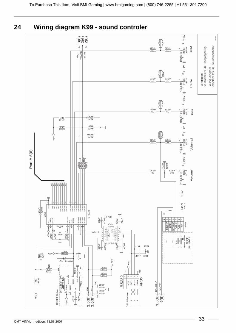
OMT VINYL – edition: 13.08.2007 33
24 Wiring diagram K99 - sound controler
To Purchase This Item, Visit BMI Gaming | www.bmigaming.com | (800) 746-2255 | +1.561.391.7200

OMT VINYL – edition: 13.08.200734
25 Wiring diagram K99 - port A
To Purchase This Item, Visit BMI Gaming | www.bmigaming.com | (800) 746-2255 | +1.561.391.7200

OMT VINYL – edition: 13.08.2007 35
26 Wiring diagram K99 - mute
To Purchase This Item, Visit BMI Gaming | www.bmigaming.com | (800) 746-2255 | +1.561.391.7200

OMT VINYL – edition: 13.08.200736
27 Wiring diagram K99 - power supply Euro 230V
To Purchase This Item, Visit BMI Gaming | www.bmigaming.com | (800) 746-2255 | +1.561.391.7200

OMT VINYL – edition: 13.08.2007 37
Wiring diagram K99 - power supply UL/USA 117V
To Purchase This Item, Visit BMI Gaming | www.bmigaming.com | (800) 746-2255 | +1.561.391.7200

OMT VINYL – edition: 13.08.200738
28 Connection diagram IR remote control/amplifier K99
CAUTIONTO REDUCE THE RISKOF FIRE REPLACE ONLYWITH SAME TYPE ANDRATING FUSE Bass Treble BGM
M
S
ONO
TEREO
ANAL HANNEL
TEREO
2-K / 2-C
S
SF
ICHERUNG
USEF1 - F4
100-240 V50Hz/60Hz
117 V60Hz
3,0 AMP250 V ACSLOW BLOW
T 4 A
30V~AC
F1
26V~AC
F2
26V~AC
F3
12V=DC
F4
I LNTERNER AUTSPRECHER
NTERNAL PEAKERI S
OP
TIO
N
OP
TIO
N
RL
EL
ES
8W
/80
W
XT
ER
NE
RA
UT
SP
RE
CH
ER
XT
ER
NA
LP
EA
KE
R
CD-TCD-T
RAFO
RANSFORMER
B -TUBBLE UBES
NT
ETZTRAFO
RANSFORMER
EERWEITERUNG
XTENSIONF
R CERNREGLER
EMOTE- ONTROL
RS
232
BG
M
IR
IR
NF
RA
RO
T-
EG
LE
R
NF
RA
RE
D-
EM
OT
E
Anschluss: INFRAROT-REGLER am VerstärkerTerminal INFRARED-REMOTE on the amplifier
A OL
R
US
GA
NG
UT
PU
T
EC
DI
CD
LR
ING
AN
G
NP
UT
EE
300m
VX
TR
A
XT
RAE
300m
VI
LR
ING
AN
G
NP
UT
MM
IKR
OF
ON
ICR
OP
HO
NE
MECHANIK
MECHANISM
D AR C
ECKEL BNEHMEN
EMOVE OVER
D AR C
ECKEL BNEHMEN
EMOVE OVER
IC 1
ntern
hannel
EC 2
xtern
hannel
Verstärker K 99
Amplifier K 99 C-UL
IR-EmpfängerIR-Receiver0060038
IR-Decoder0060039
HandsenderTransmitter0059745
Tastatur:
Keyboard:
Tastaturkabel vom Selection & CreditComputer abziehen und auf den Decoderstecken. Kabel vom Decoder auf
Unplug 12pole keyboard cable from
Selection& Credit Computer stecken.
Selection& Credit Computer and plug in the IR decoderboard.Plug cable comming from the IR decoderon the Selection & Credit Computer.
sw / bk
br
zum Münzinterfaceto the coin interface
rt / r
1br
2rt
3or4ge5gn6bl
7vi8gr
10sw11br
12rt
9ws
GND
button0
button1
button2
button3
button4
button5
button6
button8
button9
buttonR
button7
1
3
5
7
9
2
4
6
8
0
R< >
1 GND
2 Taste0
3 Taste1
4 Taste2
5 Taste3
6 Taste4
7 Taste5
8 Taste6
10 Taste8
11 Taste9
12 TasteR
9
br
rt
or
ge
gn
bl
vi
gr
sw
br
rt
ws
brrtorgegnblvigrswbrrt ws
Taste7
1
RCS-K
No.: 0059745
SELECTION
VOLUME
1 2 3
4 5 6 RESET
POWER
OPTION
7 8 9
0
- +
- +
CANCEL MUTE
INTERNCHANNEL 1
EXTERNCHANNEL 2
OP
TIO
N
OP
TIO
N
IMP
ULS
CR
ED
IT
TO
GG
LE
CO
NT.P
LA
YT
P4
P2
P5
X7
A
P1
0
P3
STA
ND
BY
OPTION:DAUERSPIELCONTINUOUSPLAY
RC
-SO
De
co
de
rN
o.:
0060039
0008942
0061262
0040441
0003877
0044117
Anschlussplan für Infrarot-Fernregleran den Verstärker K99
Connection diagram for infrared remote controlto the amplifier K99
4412-rs
0047971
1
2
4
5
T1
10
20T
+B
M LT
MemoryON
ST
1S
T2
ST
3
OFF
Selection &Credit Computer
100 - 160 - 200
K
Z
ONOFF
M3 M6 M C
Service
GP BS B4 B3 B2 B1KorbLocation
0 02
3
4
5
6
2
3
4
5
6
F
2
3
4
5
6
1
0
2
3
4
5
6
1
0
2
3
4
5
6
1
0
7T.T.+2+3
GP+6
ACHTUNG:
ATTENTION:
A :TTENTION
MEMORY-Stecker von OFFauf ON umstecken, wennTop Tunes, Popularitätszähleroder Kassenzähler arbeiten soll.
Move MEMORY Plug from OFFto ON if Top tunes, Pop Meter orCash Box Content Registrationis required.
Placer la prise MEMORY enposition ON de la position OFFsi le Top Tunes, le compteur depopularité et le contenu de lacaisse sont demandés.
P8
AVC
RS232MICRO
TAPE
MUTE
A / DNZEIGE ISPLAY
BGM
ok.
S / SCHALTER WITCHES
A /OUS FF
A /OUS FF
E /OIN N
E /OIN N
A
A
VC
VC
MODESTEREO 2-K /2CANAL HANNEL
INPUTCD TAPE
BGM
1
1
3
5
2
2
4
6
SEPARATE
NORMAL
AUTO
VOLUME
RS232
MUTE
HIGH LOW
PARALLEL
SERVICE
AUS/OFF
To Purchase This Item, Visit BMI Gaming | www.bmigaming.com | (800) 746-2255 | +1.561.391.7200

To Purchase This Item, Visit BMI Gaming | www.bmigaming.com | (800) 746-2255 | +1.561.391.7200

GermanyDeutsche Wurlitzer GmbHWurlitzerstraße 6D-32609 HüllhorstTel.: +49 (0) 57 44 - 941-0Fax: +49 (0) 57 44 - 941 [email protected]
Part no.: 0071119Wurlitzer® A Registered Trademark of the Gibson Guitar Corporation Edition 4708
R
To Purchase This Item, Visit BMI Gaming | www.bmigaming.com | (800) 746-2255 | +1.561.391.7200
David
Text Box