
Onan DKD Service Manual - RDR Reliable Diesel...
71
Caution: This document contains mixed page sizes (8.5 x 11 or 11 x 17), which may affect printing. Please adjust your printer settings according to the size of each page you wish to print. Redistribution or publication of this document by any means, is strictly prohibited.
Transcript of Onan DKD Service Manual - RDR Reliable Diesel...
Caution: This document contains mixed page sizes (8.5 x 11 or 11 x 17), which may affect printing. Please adjust your printer settings
according to the size of each page you wish to print. Redistribution or publication of this documentby any means, is strictly prohibited.

~ . ~ - . . . . _r ,. ,.- _.. . . , .
DKC, DKD MDKC, MDKD
Printed in U.S.A. 981 -0502 3-94
Redistribution or publication of this documentby any means, is strictly prohibited.

Before operating the generator set, read this manual and become familiar with it and the equipment. Safe and efficient operation can be achieved only if the unit is properly operated and maintained. Many accidents are caused by failure to follow fundamental rules and precautions. The following symbols, found throughout this manual, alert you to potentially dangerous conditions to the opera- tor, service personnel, or the equipment.
This symbol warns of immediate hazards which will result in severe personal injury or death. IQWARP(ING1 This symbol refers to a hazard or unsafe practice which can result in severe personal injury or death. b-1 This symbol refers to a hazard or unsafe practice which can result in personal injury or product or propetty damage. Read and observe each of the following safety precautions.
FUEL AND FUMES ARE FLAMMABLE Fire, explosion, and personal injury can result from im- proper practices. 0 Do not smoke or allow an open flame or spark-produc-
ing equipment near the generator set or fuel tank. Inspect the fuel lines and connections daily for leaks per the maintenance schedule.
EXHAUST GASES ARE DEADLY 0 Never sleep in the vehicle with the generator set
running unless vehicle is equipped with an operating carbon monoxide detector.
0 Inspect exhaust system daily for leaks per the maintenance schedule. Do not use engine cooling air to heat a compartment.
0 Never operate the generator set inside a building or in an area where exhaust gases could accumulate, such as near a wall or snow bank, or in high grass. When parking, make sure the exhaust outlet is not obstructed. Make sure the generator set is well ventilated.
ELECTRICAL SHOCK CAN CAUSE SEVERE PERSONAL INJURY OR DEATH
Disconnect the negative (-) cable at the starting battery before removing protective shields or touching electrical equipment. Use rubber insulative mats placed on dry wood platforms on the ground or over floors that are metal or concrete when around electrical equipment. Do not wear damp clothing (particularly wet shoes) or allow skin surfaces to be damp when handling electrical equipment.
0 Use extreme caution when working on electrical com- ponents. High voltages can cause injury or death.
0 Tag remote or open switches to avoid accidental clo- sure or starting.
0 DO NOT CONNECT GENERATOR SET DIRECTLY TO ANY BUILDING ELECTRICAL SYSTEM. Hazardous voltages can flow from the generator set into the utility line. This creates a potential for electrocution or property damage. Connect only through an approved device and after building main switch is open. Consult an electrician in regard to emergency power use.
MOVING PARTS CAN CAUSE SEVERE PERSONAL INJURY OR DEATH
0 Before starting work on the generator set, disconnect negative (-) cable at the battery. This will prevent accidental arcing or starting.
0 Keep your hands away from moving parts. 0 Make sure that fasteners on the generator set are se-
cure. lighten supports and clamps, keep guards in po- sition over fans, etc.
0 Do not wear loose clothing or jewelry while working on generator sets, because they can become caught in moving parts. Jewelry can short out electrical contacts and cause shock or burning.
0 If adjustment must be made while the unit is running, use extreme caution around hot manifolds, moving parts, etc.
GENERAL SAFETY PRECAUTIONS 0 Wear safety glasses and protective clothing when
servicing batteries. DO NOT SMOKE while servicing batteries. Lead-acid batteries emit a highly explosive hydrogen gas that can be ignited by electrical arcing or by smoking.
0 Have a fire extinguisher rated ABC nearby. Maintain extinguisher properly and become familiar with its use.
0 Benzene and lead, found in some gasoline, have been identified by some state and federal agencies as causing cancgr or reproductive toxicity. When checking, draining or adding gasoline, take care not to ingest, breathe the fumes, or contact gasoline.
0 Used engine oils have been identified by some state or federal agencies as causing cancer or reproductive toxicity. When checking or changing engine oil, take care not to ingest, breathe the fumes, or contact used oil. Remove all unnecessary grease and oil from the unit. Accumulated grease and oil can cause overheating and engine damage, which presents a potential fire hazard. Do not store anything in the generator set compad- ment such as oil or gas cans, oily rags, chains, wooden blocks, portable propane cylinders, etc. Afire could re- sult or the generator set operation (cooling, noise and vibration) may be adversely affected. Keep the com- partment floor clean and dry. Do not work on this equipment when mentally or physically .fatigued, or after consuming any alcohol o- drug that makes the operation of equipment unsafe.
.I
, ,
RGA-OP'
Redistribution or publication of this documentby any means, is strictly prohibited.

Table of Contents
SECTION TITLE PAGE SAFETY PRECAUTIONS ............................... Inside Cover
1 INTRODUCTION ............................................ 1-1 About this Manual ......................................... 1-1 How to Obtain Assistance .................................... 1-1 Test Equipment ........................................... 1-1 Safety Considerations ....................................... 1-1 Set Removal .............................................. 1-2
2
3
4
5
MARINE ENGINE CONTROL ................................... 2-1 General ................................................. 2-1 Control Description ........................................ 2.1 Control Operation .......................................... 2-3 Control Troubleshooting ..................................... 2-5
General ................................................. 3-1 Electric Start Control ....................................... 3-1 Remote Start Control ....................................... 3-7
STANDBY ENGINE CONTROL .................................. 3.1
ENGINE CONTROL SERVICE .................................. 4.1 General ................................................. 4-1 (A) BatteryCheck .......................................... 4-1 (B) Battery Cable Check ..................................... 4.1 (C) Battery Charging Check .................................. 4.1 (D) Solenoid Check ....................................... -4-1 (E) Relay Check ........................................... 4.1 (F) Fuel Solenoid Check ..................................... 4.2 (G) Switchcheck .......................................... 4-2 (H) Solenoid Check ....................................... -4-2
GENERATOR AND VOLTAGE REGULATOR ....................... 5-1 Generator Description ...................................... 5-1 Generator Operation ........................................ 5-2 Voltage Regulator .......................................... 5-3 Generator Service ......................................... 5-5
i Redistribution or publication of this documentby any means, is strictly prohibited.
Table Of COIltentS (Continued)
SECTION TITLE PAGE GENERATOR/REGULATOR TROUBLESHOOTING .................. 6-1
General ................................................. 6-1 Troubleshooting Procedures ................................. 6-2 (A) NO AC OUTPUT VOLTAGE AT RATED ENGINE RPM
(B) NO AC OUTPUT VOLTAGE AT RATED ENGINE RPM
(C) UNSTABLE OUTPUT VOLTAGE. ENGINE SPEED STABLE
(D) OUTPUT VOLTAGE TOO HIGH OR TOO LOW
(E) OUTPUT VOLTAGE TOO HIGH. TOO LOW. OR UNSTABLE
(F) FIELD BREAKER (CB21) TRIPS
(G) UNBALANCED GENERATOR OUTPUT VOLTAGE
(ELECTRONIC VOLTAGE REGULATOR) ...................... 6.3
(TRANSFORMER VOLTAGE REGULATOR) .................... 6-4
(ELECTRONIC VOLTAGE REGULATOR) ...................... 6-5
(ELECTRONIC VOLTAGE REGUMTOR) ...................... 6-5
(TRANSFORMER VOLTAGE REGULATOR) .................... 6-6
(ELECTRONIC VOLTAGE REGULATOR) ...................... 6.7
(TRANSFORMER OR ELECTRONIC VOLTAGE REGULATOR) ...... 6-7
7 GENERATOR/REGULATOR TESTS .............................. 7-1 General ................................................. 7-1 (A) Testing AC Residual Voltage ............................... 7-1 (B) Testing Commutating Reactor .............................. 7.1 (C) Testing Rectifier Bridge CR21 and Suppressor RV21 ............. 7-1 (D) Flashing the Field ....................................... 7-2 (E) Testing Reference Transformer ............................. 7-2 (F) VR21 Replacement ...................................... 7-2 (G) Testing Rotating Rectifiers ................................ 7-3 (H) Testing Exciter Stator .................................... 7-3 (J) Testing Exciter Rotor ..................................... 7-4 (K) Testing Generator Stator .................................. 7-5 (L) Testing Generator Rotor .................................. 7-6 (M) Wiring Harness Check ................................... 7-7 (N) Testing Regulating Transformer T21 ......................... 7-7 (P) Voltage Adjustment ...................................... 7-8 (a) Reconnection .......................................... 7-8
8 WIRING DIAGRAMS ......................................... 8-1
ii Redistribution or publication of this documentby any means, is strictly prohibited.

Section 1 Introduction
ABOUT THIS MANUAL For servicing purposes, the generator set can be divided into three basic parts: the engine, the generator, and the control. This manual contains troubleshooting and repair information for the generator and the control. Refer to the Engine Service Manual (981 -0501) when servicing the engine.
Study this manual carefully and observe all the warn- ings and cautions throughout the manual. Knowing the generator set, using it properly, and following a regular maintenance schedule can result in longer unit life, better performance and safer operation.
Information for printed circuit board repair is limited because it is more efficient to replace the boards in the field and repair them at the factory. Application of meters or hot soldering irons to printed circuit boards by other than qualified service personnel can cause unneces- sary and expensive damage.
This manual contains basic wiring diagrams and sche- matics that are included to help in troubleshooting. Ser- vice personnel should use the actual wiring diagram and schematic shipped with each unit. The wiring dia- grams and schematics that are maintained with the unit should be updated when modifications are made to the unit.
HOW TO OBTAIN ASSISTANCE Always give the complete model number and serial number as shown on the Onan nameplate when seek- ing additional service information or replacement parts.
TEST EQUIPMENT Most of the test procedures in this manual can be per- formed with a multimeter such as the Simpson Model 260 VOM or with a digital VOM. Additional instruments used to service generator sets that should be available are:
AC Voltmeter DC Voltmeter Frequency Meter Jumper Leads Load Test Panel Megger or Insulation Resistance Meter Frequency Meter or Strobotach Variac Wheatstone Bridge or Digital Ohmmeter
Incorrect service or replacement of lZCEHE4 parts can result in severe personal injury, death, and /or equipment damage. Service per- sonnel must be qualified to perform electrical and mechanical service.
SAFETY CONSIDERATIONS Always consider the safety aspects of any service procedure. Generator sets present several safety hazards that the service person must be aware of to safely complete the job. Read through the safety precau- tions listed on the inside cover and familiarize yourself with the hazards shown in Table 1-1. Once the hazards are known, approach the job with a safety conscious attitude. Being safety conscious is the most effective way to avoid injury to yourself or others. Reduce the chance that an accident will occur by adopting the following safeguards.
Safeguards to Avoid Hazards Use personal protection - Protect your body by wearing the appropriate safety equipment. Protec- tive clothing includes safety shoes, gloves, safety glasses, and hard hats. Leave rings and jewelry off and do not wear loose clothing that might get caught on equipment.
0 Work to Reduce the Hazard - The workshop area and all pieces of equipment used can contribute to reducing the hazard potential. Keep guards and shields in place on machinery and maintain equip- ment in good working order. Store flammable liq- uids in approved containers awayfrom open flame, spark, pilot light, cigarette, or other ignition source. Keep the workshop clean and well-lighted, and provide adequate ventilation. Keep fire extinguisher and safety equipment nearby and be prepared to respond to an emergency.
0 Develop Safe Work Habits - Unsafe actions are identified as the source of most accidents involving the use of tools and machines. Be familiar with the equipment and know how to use it safely. Use the correct tool for the job and check its condition before starting. Observe the warnings and cautions in this manual and take special precautions when working around electrical equipment. Do not work alone if possible and do not take risks.
1-1 Redistribution or publication of this documentby any means, is strictly prohibited.

TABLE 1-1. HAZARDS AND THEIR SOURCE
0 Fire and Explosions -Leaking or spilled fuel -Hydrogen gas from battery -Oily rags improperly stored -Flammable liquids improperly stored
0 Burns -Hot exhaust pipes -Hot engine and generator surfaces -Electrical short in DC wiring system
-Carbon monoxide from faulty exhaust pipes, joints or hangers
-Operating generator set where exhaust gases can accumulate
Poisonous Gases
0 Electrical Shock (AC) -Improper generator set load connections -Faulty load circuit -Faulty electrical appliance -Faulty generator set wiring -Working in damp conditions -Jewelry touching electrical components
-Jewelry or loose clothing catching in moving parts
-Leaking or spilled oil
Rotating Machinery
0 Slippery Surfaces
0 Heavy Objects -Removing generator set from RV -Removing heavy components
Be prepared if an accident does occur. Numerous agencies such as the Red Cross and local police and fire departments offer basic courses in first aid, CPR, and fire control. Take advantage of these offerings so you are ready to respond when an accident occurs. Learn to be safety conscious and make safe practices a part of your work routine. Do not work when tired or after consuming any alcohol or drug that makes the opera- tion of equipment unsafe.
SET REMOVAL Some service procedures will require removing the generator set from a vehicle or boat. Because of the wide variety of generator set installations, it is not possi- ble to specify the exact removal procedures for each generator set. If, after examining the installation, a satis- factory method for removing the set cannot be deter- mined, contact the vehicle or boat manufacturer or the generator set installer to obtain their recommendations.
Generator sets are heavy and they lZEEEl can cause severe personal injury or death if dropped during removal. Use adequate lifting devices to provide sufficient support for the set. Keep hands and feet clear while lifting the generator set.
Disconnecting Generator Set Systems Some installations may require partial removal of the set to gain access to the battery cable, fuel line, and other connections. Read this entire section before starting set removal. The following steps are a general guideline for set removal.
Leakage of fuel in or around the [BWARNINGI generator set compartment presents the hazard of fire or explosion that can cause severe personalinjury or death. Do not disconnect or connect battery cables if fuel vapors are present. Ventilate the compartment thoroughly, use bilge blowers or power exhausters in boats, and park vehicles outdoors in a well ventilated area.
1. Disconnect the generator set negative (-) battery
2. Disconnect the generator set positive (+) battery
cable at the battery terminal.
cable from the wire harness.
3. Disconnect the remote control plug wire from the generator set, if applicable.
4. Disconnect the generator load wires and tag for identification when reconnecting.
5. Disconnect the exhaust system and support brackets or hangers to allow set removal.
6. Disconnect the fuel line at the generator set hous- ing. Securely plug the end of the fuel line to prevent fuel leakage or an accumulation of explosive gaso- line vapor.
7. Verify that the generator set is adequately sup- ported before loosening any of the mounting bolts or support members.
1 -2 Redistribution or publication of this documentby any means, is strictly prohibited.

Leakage of fuel presents fhe hazard @!@!!%I of fire or explosion that can cause severe personal injury or death. Make certain all fuel line openings are plugged to prevent gasoline vapor from accumulating. Before disconnecting the fuel line, be certain there are no ignition sources such as flame, spark, pilot light, cigareite, etc., near the generator set. Keep an ABC type fire extinguisher nearby.
When reinstalling the generator set, be sure all mount- ing hardware, and electrical, exhaust, and fuel system componentsare connected exactly as they were before removal. Refer to the appropriate installation manual during reinstallation for important safety precautions.
Check for oil and fuel leaks. Check exhaust system audibly and visually with the generator set running. Repair any leaks immediately. Replace worn, damaged, or corroded exhaust and fuel line components before leaks occur.
1-3 Redistribution or publication of this documentby any means, is strictly prohibited.

Redistribution or publication of this documentby any means, is strictly prohibited.

Section 2. Marine Engine Control
GENERAL The marine engine control system includesall thefunc- tions that relate to the operation of the engine. This includes starting and stopping, instrumentation, moni- toring for fault conditions, and battery charging. This section covers a description of the controls and shows where they are located, describes how the control operates, and provides basic troubleshooting pro- cedures.
CONTROL DESCRIPTION Gauges/Meters and Switches Oil Pressure Gauge (0ptional):Shows engine lubricat- ing oil pressure. The gauge hasa range of 0 to 100 psi (0 to 700 kPa) and is connected to an engine sensor. See Figure 2-1.
Coolant Temperafure Gauge (Optional): The water temperature should be in the range of 165OF to 195°F (74°C to 91 "C) depending on the load and the ambient temperature.
TRANSFORMER REGULATOR
DC Voltmeter (Optional): Normal battery B+ voltage dur- ing operation should be 13.5 to 15 volts on a 12-volt system; 27 to 30 volts on a 24-volt system.
Starf/Stop Switch S77:Starts and stopsthe unit locally. Unit may be operated from an optional remote switch wired to the control panel. Preheat added to stop posi- tion on later production sets.
Preheat Switch S72: Activates heater relay K13 to con- nect battery B+ to the engine glow plugs prior to starting the engine. S12 is not used on later production sets.
Fault Reset:A manual reset breakerthat shuts down the engine for low oil pressure, high coolant temperature, high exhaust temperature, and overspeed (option).
Emergency Stop DC Control Breaker: A 15-ampere breaker providing protection to the control box wiring and remote wiring from short circuits or overload. Also serves as an emergency stop switch.
EL ECTR 0 N I C REGULATOR BOARD
/\
Redistribution or publication of this documentby any means, is strictly prohibited.

Control Components The following describes the basic engine control com- ponents and how they function.
Engine Monitor Circuit Board; A printed circuit board that monitors engine control system functions. This includes starting, stopping, and fault system operation. A terminal board is included for making remote connec- tions. See Figure 2-1.
K71 Start Solenoid: Located over the engine monitor circuit board. It connects the battery B+ to the starter solenoid B1 during cranking.
K73 HeaterRelay: Located On the relay mounting tray. It C O m ~ ~ t s t h e battery B+to the engine glow Plugs Prior to and during cranking. It is energized by the Preheat Switch (S12 early production/Sll late production) and the start switch S11 during start sequence.
Two relays are soldered to the circuit board that are not serviceable. Power Relay K12 connects and maintains battery B+ to the control meters and fuel solenoid during operation. Starter Protection Relay K15 is an AC oper- ated relay. When the start switch is actuated, B+ is connected to the K11 start solenoid through K15 NC contacts until the generator output reaches 90 volts AC. K15 activates and disconnects the starter.
F7 In l ine Fuse: A 30-ampere fuse is located in afuse- holder connected to the B+ terminal of the starter. This fuse connects B+ to the control and it will open if ashort or overload should occur.
K7 Fue/So/enoid:Opens the fuel control valve when the start/stop switch is placed in the Start position.
K74 Fuel Solenoid Relay: Located on the relay mount- ing tray. It is energized only during cranking and con- nects B+ to the fuel solenoid K1, fuel pump E5, and fault breaker CB12 circuits.
K76 Start Disconnect Relay: Located on the relay mounting tray. It is connected through CRl l to the 12- volt battery charging alternator. The relay actuates at 5.5 to 7.5 volts DC. The K16 relay and CRl l diode are not used on later production sets and were disconnected on some sets (refer to Product Support Bulletin 450).
Engine Sensors The following briefly describes the engine mounted sensors and switches, and how they protect the engine from adverse operating conditions.
OPTIONAL OIL PRESSURE CONTROL
OPTIONAL COOLANT TEMPERATURE SENDER
E2 BREAKER
CB12
OPTIONAL OVERSPEED
SWITCH s4
FIGURE 2-2. MDKClMDKD FAULT SENSOR LOCATION ES-1445-2
2-2 Redistribution or publication of this documentby any means, is strictly prohibited.

All safety sensors (switches) close to ground if abnormal operating conditions exist and trip the fault breaker CB12 to stop the engine. See Figure 2-2.
Resistance units and switches in the monitoring and shutdown systems are sealed units and are not repair- able. When replacing a sensor, do not use a substitute item since resistance units are matched to the gauge they supply. Cutoff switches are close tolerance parts made for a specific application.
Oil Pressure Monitors Refer to Figure 2-2 for the location of the oil pressure sensors.
Oil Pressure Sender E l (Optional): The sender resist- ance changes with oil pressure and results in a reading on the oil pressure meter. The meter range is 0 to 100 psi (0 to 700 kPa).
Low Oil Pressure Switch S1: This switch closes if oil pressure drops to 9 psi (62 kPa), activating the fault breaker and stopping the engine.
Control PowerLafch S6:This oil pressure switch closes at 5 psi (34 kPa) and provides a latch function for the control circuits. When closed, the switch supplies a ground path for relay K12 on the engine monitor board.
Overspeed Switch (Optional) The mechanical overspeed switch is mounted on the front of the engine crankshaft as shown in Figure 2-3. It is factory adjusted to close and shut down 60 hertz units at 2200 r/min +/- 90 rimin; 50 hertz unitsat 1900 rimin t/- 90 r/min. An overspeed condition grounds the shutdown circuit on the Engine Monitor Board and trips the fault breaker. After the problem is corrected, starting will not occur until the breaker is reset.
If necessary, the speed trip point can be corrected by turning the adjusting screw, to adjust the magnetic air gap (see Figure 2-3). An accurate tachometer or strob- otach is needed to check the overspeed trip point after adjustment is made. The air gap must not be less than 0.005 inch (0.13 mm).
Engine Temperature Monitors Refer to Figure 2-2 for the location of the engine temperature sensors.
Coolant Temperature Sender €2 (0ptional):The resist- ance of the sender unit changes with theengine coolant temperature and causes a reading of the Water Temp Meter. The meter range is 100OF to 25OOF (4OOC to 121OC).
High Coolant Temperature Switch S2: This switch closes if the coolant temperature rises to 222OF (1 OSOC), activating the fault breaker and stopping the engine.
High Exhaust Temperature Switch S5: This switch is mounted on the exhaust elbow and it closes on temper- ature rise above 23OOF (llO°C), activating the fault breaker and stopping the engine. It will open again when the temperature reaches about 190°F (88°C).
High exhaust elbow temperature is caused by insuffi- cient or lack of sea water flow. Sea water flow at the exhaust outlet should be about 3 gal/min (1 1 litre/min).
SWITCH CONT
ES-1514
FIGURE 2-3. OPTIONAL OVERSPEED SWITCH
CONTROL OPERATION Trouble-free operation of the control system should be the major concern of generator set service personnel. Service personnel must thoroughly understand how the controls operate, know how to make the proper adjust- ments, replacements, or repairs in a reasonableamount of time.
The following section covers the control operation. The schematic diagram shown in Figure 2-4 can be used to help follow the circuit description. Always refer to the specific wiring diagram that corresponds to the model and specification number of the generator set when troubleshooting. Relay contact references normally open (NO) and normally closed (NC) refer to the position of the contacts with the unit at rest (not energized).
Priorto starting the generator set, Check the fuel supply, engine oil level, and battery connections for loose or broken wires. Check the entire exhaust system for worn or corroded parts. Replace defective parts before leaks occur.
2-3 Redistribution or publication of this documentby any means, is strictly prohibited.
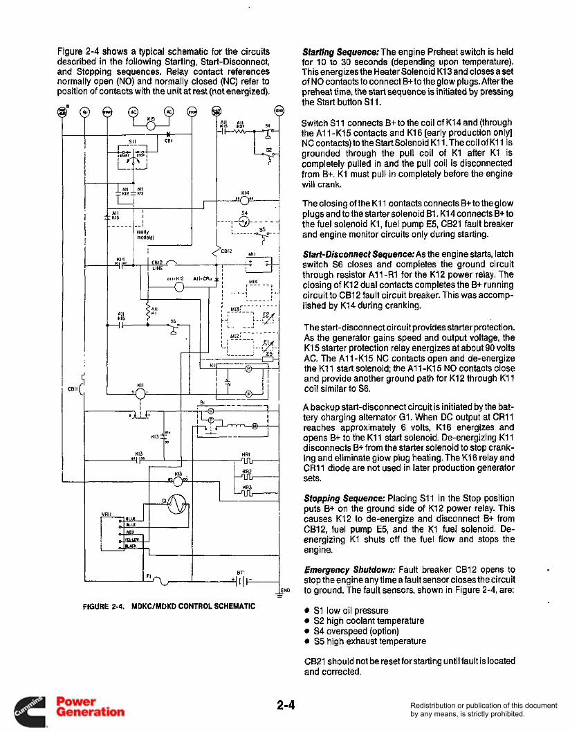
Figure 2-4 shows a typical schematic for the circuits described in the following Starting, Start-Disconnect, and Stopping sequences. Relay contact references normally open (NO) and normally closed (NC) refer to position of contacts with the unit at rest (not energized).
! I
I i
JND - - FIGURE 2-4. MDKWMDKD CONTROL SCHEMATIC
Starting Sequence: The engine Preheat switch is held for 10 to 30 seconds (depending upon temperature). This energizes the Heater Solenoid K13 and closes aset of NO contacts to connect B+ to the glow plugs. After the preheat time, the start sequence is initiated by pressing the Start button Sl l .
Switch S11 connects B+ to the coil of K14 and (through the A1 1 -K15 contacts and K16 [early production only] NC contacts) to the Start Solenoid K1 1. The coil of K11 is grounded through the pull coil of K1 after K1 is completely pulled in and the pull coil is disconnected from B+. K1 must pull in completely before the engine will crank.
The closing of the K11 contacts connects B+ to the glow plugs and to the starter solenoid B1. K14 connects B+ to the fuel solenoid K1, fuel pump E5, CB21 fault breaker and engine monitor circuits only during starting.
Start-Disconnect Sequence:As the engine starts, latch switch S6 closes and completes the ground circuit through resistor A l l -R1 for the K12 power relay. The closing of K12 dual contacts completes the B+ running circuit to CB12 fault circuit breaker. This was accomp- lished by K14 during cranking.
The start-disconnect circuit provides starter protection. As the generator gains speed and output voltage, the K15 starter protection relay energizes at about 90 volts AC. The A1 1 -K15 NC contacts open and de-energize the K11 start solenoid; the A1 1-K15 NO contacts close and provide another ground path for K12 through K11 coil similar to S6.
A backup start-disconnect circuit is initiated by the bat- tery charging alternator G1. When DC output at CR11 reaches approximately 6 volts, K16 energizes and opens B+ to the K11 start solenoid. De-energizing K11 disconnects B+ from the starter solenoid to stop crank- ing and eliminate glow plug heating. The K16 relay and CR11 diode are not used in later production generator sets.
Stopping Sequence: Placing S11 in the Stop position puts B+ on the ground side of K12 power relay. This causes K12 to de-energize and disconnect B+ from CB12, fuel pump E5, and the K1 fuel solenoid. De- energizing Kl shuts off the fuel flow and stops the engine.
Emergency Shutdown: Fault breaker CB12 opens to stop the engine any time afault sensor closes the circuit to ground. The fault sensors, shown in Figure 2-4, are:
0 S1 low oil pressure 0 S2 high coolant temperature 0 S4 overspeed (option) 0 S5 high exhaust temperature
CB21 should not be reset for starting until fault is located and corrected.
Redistribution or publication of this documentby any means, is strictly prohibited.
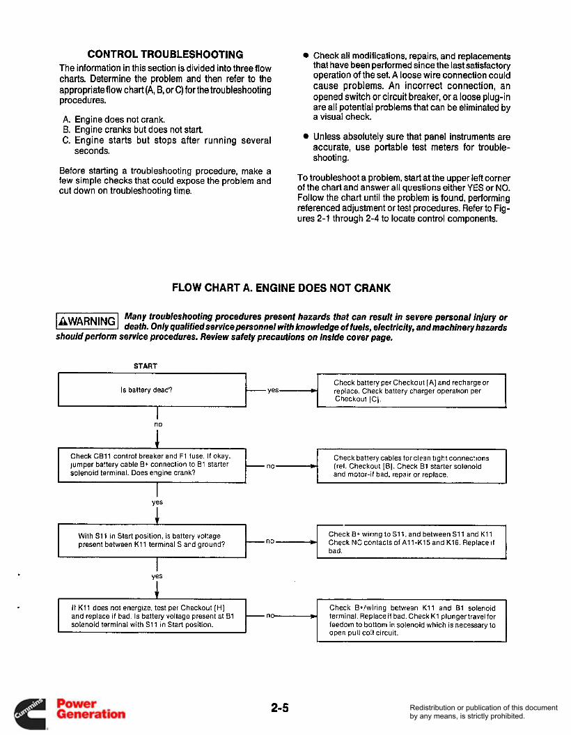
CONTROL TROUBLESHOOTING The information in this section is divided into three flow charts. Determine the problem and then refer to the appropriate flow chart (A, B, or C) for the troubleshooting procedures.
Check all modifications, repairs, and replacements that have been performed since the last satisfactory operation of the set. A loose wire connection could cause problems. An incorrect connection, an opened switch or circuit breaker, or a loose plug-in are all potential problems that can be eliminated by
With S11 in Start position, is battery voltage present between K11 terminal S and ground? no W
A. B. C.
Check B+ wiring toSl1. and betweenS11 and K11 Check NC contacts of A11-Kl5 and K16. Replace 11 bad.
Engine does not crank. a visual check.
I t K11 does not energize, test per Checkout [HI and replace if bad. Is battery voltage present at B1 solenoid terminal with S11 in Start position.
Engine cranks but does not start. Engine starts but stops after running several seconds.
Unless absolutely sure that panel instruments are accurate, use portable test meters for trouble- shooting.
Check Btlwiring between K11 and B1 solenoid terminal. Replaceif bad. Check K1 plungertravel for feedom to bottom in solenoid which is necessary to
nn
Before starting a troubleshooting procedure, make a few simple checks that could expose the problem and cut down on troubleshooting time.
Totroubleshoot a problem, Start at the upper left corner of the chart and answer all questions either YES or NO. Follow the chart until the problem is found, performing referenced adjustment or test procedures. Refer to Fig- ures 2-1 through 2-4 to locate control components.
FLOW CHART A. ENGINE DOES NOT CRANK
Many troubleshooting procedures present hazards that can result in severe personal injury or b@!%l death. Only qualified service personnel with knowledge of fuels, electricity, and machinery hazards should perform service procedures. Review safety precautions on inside cover page.
START
Check batteryper Checkout [A ] and rechargeor replace. Check battery charger operation per Checkout [Cl.
Is battery dead?
no
1 Check C B l l control breaker and F1 fuse. If okay. jumper battery cable B+ connection to E1 starter silenoid terminal. Does engine crank?
Check battery cables for clean tight connections (rel. Checkout [B]. Check B1 starter solenoid and motor-if bad. repair or replace.
ves
1
1
2-5 Redistribution or publication of this documentby any means, is strictly prohibited.

FLOW CHART B. ENGINE CRANKS BUT DOES NOT START
Is engine getting fuel? Exhaust smoke should be blue-white and fuel flow steady from fuel return line.
Many troubleshooting procedures present hazards that can result in severe personal injury or k!@%@l death. Only qualified service personnel with knowledge of fuels, electricity, andmachinery hazards should perform service procedures. Review safety precautions on inside cover page.
Check fuel system: fuel tank level, shut-off valves, fuel lines and connections, fuel filters, fuel pump and injection pump. Okay?
START I 1
Does K1 fuel solenoid energize when S11 is in Start position?
r
Is a fault condition indicated by fault breaker CB12 on control panel.
Check for a possible fault condition. If none,
breaker CB12 for improper wiring. Yes * check fault monitors S1 through S5 and fault
1
Does latching relay K12 energize and contacts close when generator set comes up to operating speed?
no *
Is battery B+ applied to glow plug heaters when Preheat Switch is closed?
Check for closing of S6 power latch switch. If okay, replace engine monitor PC board.
3
Yes 5 Does DC control breaker trip when the generator set is started?
Check all B+ wiring for shorts to ground.
1
I Check B+ circuit through S11. Test S11 per Checkout [GI. Test K1 per Checkout [F]. I
I no
yes I 1 Incorrect fuel? See Operator’s Manual recommendations.
Check Preheat switch and heater relay K13 per Checkouts [GI and [a. Check heater wiring.
FLOW CHART C. ENGINE STARTS BUT STOPS AFTER RUNNING SEVERAL SECONDS
Many troubleshooting procedures present hazards that can result in severe personal injury or death. Only qualified service personnel with knowledge of fuels, electricity, and machinery hazards
should perform service procedures. Review safety precautions on inside cover page.
2-6 Redistribution or publication of this documentby any means, is strictly prohibited.
Section 3. Standby Engine Controls
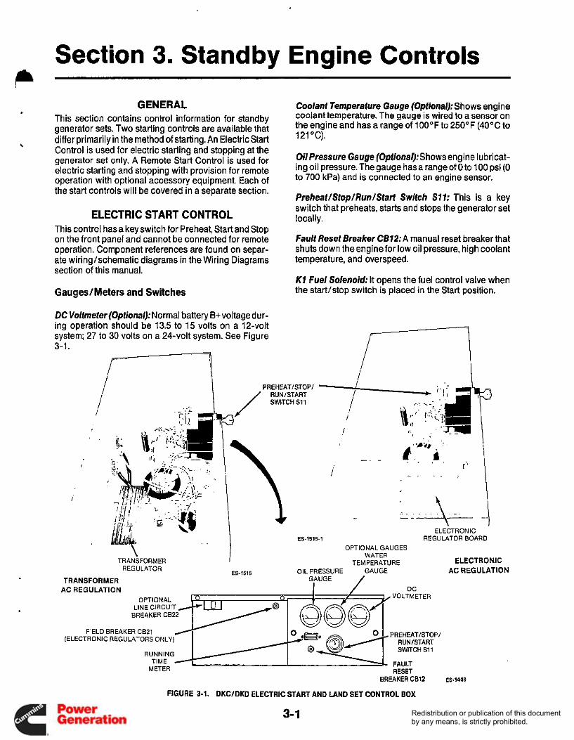
GENERAL This section contains control information for standby generator sets. Two starting controls are available that differ primarily in the method of starting. An Electric Start Control is used for electric starting and stopping at the generator set only. A Remote Start Control is used for electric starting and stopping with provision for remote operation with optional accessory equipment. Each of the start controls will be covered in a separate section.
b
ELECTRIC START CONTROL This control has a key switch for Preheat, Start and Stop on the front panel and cannot be connected for remote operation. Component references are found on separ- ate wiringlschematic diagrams in the Wiring Diagrams section of this manual.
GaugesIMeters and Switches
.
DC Voltmeter(0ptional)~Normal battery B+ voltage dur- ing operation should be 13.5 to 15 volts on a 12-volt system; 27 to 30 volts on a 24-volt system. See Figure 3-1.
Coolant Temperature Gauge (Optional): Shows engine coolant temperature. The gauge is wired to a sensor on the engine and has a range of 100°F to 250°F (40°C to 121 "C).
Oil Pressure Gauge (Optional): Shows engine I u b r i cat- ing oil pressure. The gauge has a range of 0 to 100 psi (0 to 700 kPa) and is connected to an engine sensor.
frelreat/Stop/Run/Start Switch S77: This is a key switch that preheats, starts and stops the generator set locally.
fault Reset Breaker C612: A manual reset breaker that shuts down the engine for low oil pressure, high coolant temperature, and overspeed.
K1 fuel Solenoid: It opens the fuel control valve when the start/stop switch is placed in the Start position.
I
WATER TEMPERATURE ELECTRONIC
AC REGULATION TRANSFORMER I
REGULATOR ES-1515 OIL PRESSURE GAUGE TRANSFORMER
AC REGULATION DC VOLTMETER
PREHEATISTOPI RUNISTART SWITCH S11
FIELD BREAKER CB21 (ELECTRONIC REGULATORS ONLY)
FAULT RESET
TIME / METER
BREAKER C812 ES-1448
FIGURE 3-1. DKCIDKD ELECTRIC START AND LAND SET CONTROL BOX
3-1 Redistribution or publication of this documentby any means, is strictly prohibited.

F7 I n l i n e Fuse: A 30-ampere fuse is located in a fuse holder connected to the B+ terminal of the starter. This fuse connects B+ to the control and opens if a short or overload should occur.
Resistance units and switches in the monitoring and shutdown systems are sealed units and are not repaira- ble. When replacing a sensor, do not use a substitute item since resistance units are matched to the gauge they supply. Cutoff switches are close tolerance parts made for a specific application. ,
Oil Pressure Monitors Refer to Figure 3-2 for the location of the oil pressure sensors.
Oil Pressure Sender E7 (Optional): The sender resist- ance changes with oil pressure and results in a reading on the oil pressure meter. The meter range is 0 to 100 psi (0 to 700 kPa).
Low Oil Pressure Switch S7: This switch closes if oil pressure drops to 9 psi (62 kPa), activating the fault breaker and stopping the engine.
LOW OIL PRESSURE
OIL PRESSURE SENDER E l
HIGH COOLANT TEMP SWITCH-
52
F1 FUSEH
Engine Temperature Monitors Refer to Figure 3-2 for the location of the engine temperature sensors.
Coolant Temperature SenderE2 (0ptional):The resist- ance of thesender unit changes with theengine coolant temperature and causes a reading on the Water Temp rneter.Themeterrangeis100" to25O0F(4O0 to121"C).
High Coolant Temperature Switch S2: This switch closes if the coolant temperature rises to250"F (121 "C), activating the fault breaker CB12 and stopping the engine.
I
OPTIONAL COOLANT TEMPEFWTU,RE SENDER E2
FIGURE 3-2. DKCIDKD ELECTRIC START FAULT SENSOR LOCATION
3-2 Redistribution or publication of this documentby any means, is strictly prohibited.

Overspeed Switch (Optional) The mechanical overspeed switch is mounted on the front of the engine crankshaft as shown in Figure 3-3. It is factory adjusted to close and shut down 60 hertz units at2200+/-90r/min;50hertzunitsat1900r/min+/-90 r/min. An overspeed condition grounds the shutdown circuit on the Engine Monitor Board and trips the fault breaker. After the problem is corrected, starting will not occur until the fault breaker is reset.
S co
ES-1514
FIGURE 3-3. OPTIONAL OVERSPEED SWITCH
If necessary, the speed range can be corrected by turn- ing the adjusting screw, thereby changing the magnetic air gap. An accurate tachometer or strobotach is needed to check the overspeed trip point after adjust- ment is made. The air gap must not be less than 0.005 inch (0.1 3 mm).
Control Operation Trouble-free operation of the control system should be the major concern of generator set service personnel. Service personnel must thoroughly understand how the controls operate, know how to make the proper adjust- ments, replacements, or repairs in a reasonable amount of time.
Prior to starting the generator set, check the fuel supply, engine oil level, and all battery connections for loose or broken wires.
Figure 3-4 shows a schematic diagram for the circuits described in the following Starting, Start-Disconnect and Stopping sequences. Relay contact references normally open (NO) and normally closed (NC) refer to position of contacts with the unit at rest (not energized).
Starting Sequence: When the control key switch S11 is in the Preheat position, contacts 1-2 connects B+ to the glow plug heaters. See Figure 3-4.
In the Start position, S11 contacts 1-2, 3-4 and 5-6 close. Contacts 1-2 energize the glow plugs during cranking; contacts 3-4 connect B+ to CB12 Fault breaker, K1 fuel solenoid, S4 overspeed switch and VR11 battery charging voltage regulator; contacts 5-6 connect B+ to the starter solenoid B1.
In the Run position, S11 contacts 3-4 and 7-8 close. Contacts 3-4 remain closed and maintain B+ to CB12, K1, S4 and VR11. Contacts 7-8 connect B+ to the engine fault sensors S1 and S2. Contacts 1-2 open the glow plug heater circuit, and contacts 5-6 open the starter solenoid circuit
Start-Disconnect Sequence: This function is completed manually when keyswitch S11 is released from the Start position opening Si1 contacts 5-6 for the starter sole- noid B1.
Stopping Sequence: This function is completed manu- ally when key switch S i 1 is turned to the Stop position. This opens all switch contacts and removes B+from the fuel solenoid K1. De-energizing K1 shuts off the fuel flow and stops the engine.
Emergency Shutdown: Fault breaker CB12 opens and disconnects B+from the fuel solenoid K1 anytime a fault sensor closes the circuit to ground. The fault sensors are:
S1 low oil pressure 0 S2 high engine temperature 0 S4 overspeed
CB12 should not be reset for starting until fault is located and corrected.
.
3-3 Redistribution or publication of this documentby any means, is strictly prohibited.

--. !tl I _c 4 t i
HRI -+
Control Troubleshooting The information in this section is divided into three flow charts. Determine the problem and then refer to the appropriate flow chart (A,B, or C) for the troubleshooting procedures.
A. Engine does not crank. B. Engine cranks but does not start. C. Engine starts but stops after running several
seconds.
Before starting a troubleshooting procedure, make a few simple checks that may expose the problem and cut down on troubleshooting time.
Check all modifications, repairs, and replacements performed since last satisfactory operation of set. A loose wire connection overlooked when installing a replacement part could cause problems. An incor- rect connection, an opened switch or circuit breaker, or a loose plug-in are all potential prob- lems that can be eliminated by a visual check.
Unless absolutely sure that panel instruments are accurate, use portable test meters for trouble- shooting.
To troubleshoot a problem, start at the upper-left corner of chart and answer all questions either YES or NO. Follow the chart until the problem is found, performing referenced adjustments or test procedures. Refer to Figures 3-1 through 3-4 for locating control compo- nents, leads, terminals and other check points.
FIGURE 3-4. ELECTRIC START CONTROL SCHEMATIC DIAGRAM
3-. 4 Redistribution or publication of this documentby any means, is strictly prohibited.
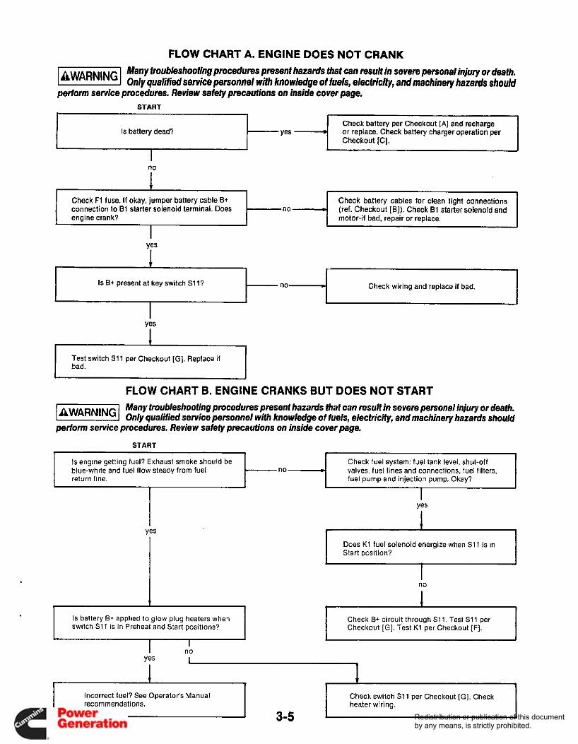
FLOW CHART A. ENGINE DOES NOT CRANK Many tmubleshootingpmcedures present hazards that can resutf in severe personalinjury or death. lliEEEl only qualijiec, service personnel with knowidge of fuels, electricity, and machinery /manis should
perform service procedures. Review safefy precautions on inside cover page.
Is battery dead? Check battery per Checkout [A] and recharge or replace. Check battery charger operation per Checkout IC].
yes
no w engine crank?
I Does K1 fuel solenoid energize when S11 is in Start position? I
Check battery cables for clean tight connections (ref. Checkout [B]). Check 81 starter solenoid and motor-if bad, repair or replace.
no * Is B+ present at key switch S l l ? Check wiring and replace if bad,
I s engine getting fuel? Exhaust smoke should be blue-white and fuel flow steady from fuel return line.
Check fuel system: fuel tank level, shut-off valves, fuel lines and connections, fuel filters, fuel pump and injection pump. Okay?
&
IS battery B+ applied to glow plug heaters when switch S11 is in Preheat and Start positions?
Check B+ circuit through S11. Test S11 per Checkout (GI. Test K1 per Checkout [F].
Incorrect fuel? See Operator's Manual 1
Check switch 311 per Checkout [GI. Check
Redistribution or publication of this documentby any means, is strictly prohibited.

FLOW CHART C. ENGINE STARTS BUT STOPS AFTER RUNNING SEVERAL SECONDS
Many troubleshooting procedures present hazards that can result in severe personal injury or 1aWAR"Gl death. Only qualified service personnel with knowledge oi fuels, electricity, andmachinery hazards should perform service procedures. Review safety precautions on inside cover page.
START
Is a fault condition indicated by fault breaker CB12 on control panel?
Check for a possible fault condition. If none, check fault monitors S1, S2, S4 and fault breaker CB12 for improper wiring.
no
Test key switch S11 per Checkout [GI. Check wiring. Check fuel system. I
3-6 Redistribution or publication of this documentby any means, is strictly prohibited.
REMOTE START CONTROL This control can provide starting and stopping from remote locations when connected to optional acces- sory equipment. The following text explains control conponents function, control operation and trouble- shooting.
OilPressure Gauge (0ptional):Shows engine lubricat- ing oil pressure. The gauge has a range of 0 to 100 psi (0 to 700 kPa) and is connected to an engine sensor. See Figures 3-5 and 3-6.
Coolant Temperature Gauge (Optional): The water temperature should be in the range of 165OF to 195OF (74°C to 91OC) depending on the load and ambient temperature.
DC Voltmeter(0ptional): Normal battery B+ voltage dur- ing operation should be 13.5 to 15 volts on a 12-volt system; 27 to 30 volts on a 24-volt system.
Preheat Switch S72:Activates heater relay K13 to con- nect battery B+ to the engine glow plugs prior to starting the engine.
Start-Stop Switch: Starts and stops the unit locally. When released, unit may be operated from a remote switch wired to the control panel.
DC Control Breaker CB7 7:A 1 5 ampere breaker provid- ing protection to the control box wiring and remote wiring from short circuits or overload. Also serves as an emergency stop switch.
Fault Reset Breaker CB72:A manual reset breaker that shuts down the engine for low oil pressure, high coolant temperature, high exhaust temperature and overspeed.
Battery Charge Breaker CB13 (RV Generator sets): A 15-ampere breaker protecting the DCvoltage regulator, alternator and wiring from short circuits or overload.
In-Line Fuse F7 (Land Generator sets): A 30 ampere fuse is located in a fuseholder connected to the B+ terminal of the starter. This fuse connects B+ to the control and opens if a short or overload should occur.
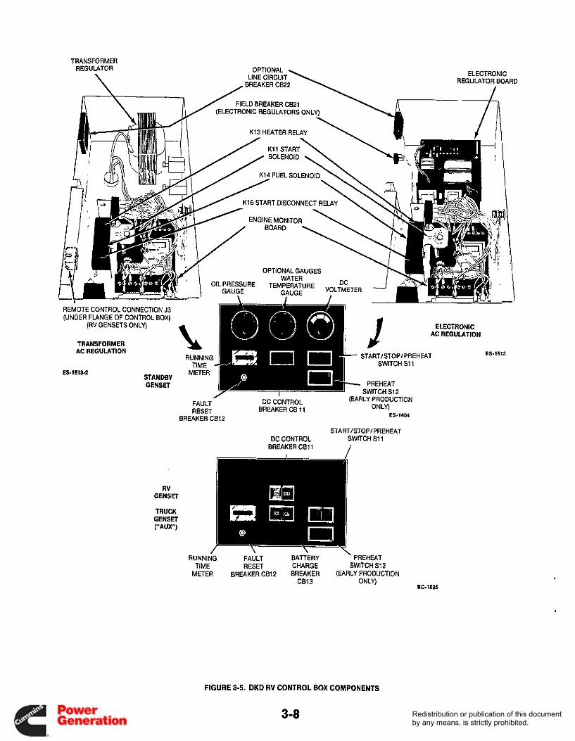
Engine Monitor Circuit Board: A printed circuit board that monitors engine control system functions. This includes starting, stopping, and fault system operations. A terminal board is included for making remote connec- tions. See Figure 3-5.
Two relays are soldered to the circuit board and are not serviceable. Power relay K12 connects and maintains battery B+ to the control meters and fuel solenoid during operation. Starter protection relay, K15 energizes at about 90 volts AC. The A1 1 -K15 NC contacts open and de-energize the K11 start solenoid; the A11-Kl5 NO contacts closeand provideanother ground path for K12 through K11 coil similar to S6.
K1 fuelSolenoid:Opens the fuel control valve when the start/stop switch is placed in the Start position.
K71 Start Solenoid: Located over the engine monitor circuit board. It connects battery B+ to the starter sole- noid B1 during cranking.
K13 Hoaror Relay:Located on the relay mounting tray. It connects battery B+ to the engine glow plugs prior to cranking. It is energized by S12 preheat switch.
K74 Fuel Solenoid Relay: Located on the relay mount- ing tray. It is energized only during cranking and con- nects B+ to the fuel solenoid K1, fuel pump E5 and fault breaker CB12 circuits.
K16 Start Disconnect Relay: Located on the relay mounting tray. It is connected through CRl l to the 12- volt battery charging alternator. The relay actuates at about 6 volts DC. The K16 and C R l l diode are not used on later production sets and were disconnected on some sets (refer to Product Support Bulletin 450).
3-7 Redistribution or publication of this documentby any means, is strictly prohibited.
TRANSFORMER REGUIATOR
\ OPTIONAL
LINE CIRCUIT ELECTRONIC REGULATOR BOARD
/ FIELD BREAKER CB21 (ELECTRONIC REGULATORS ONLY)
-\ I I K13 HEATER RELAY \
REMOTE CONTROL CONNECTION J3 (UNDER FLANGE OF CONTROL BOX)
(RV GENSETS ONLY)
TRANSFORMER AC REGULATION
STANDBY GENSET
ES-1513-2
I RUNNING
TIME METER
I
ELECTRONIC AC REGULATION
STARTISTOP I PREH EAT ES-1513
SWITCH S11
PREHEAT SWITCH S12
UCTION ~
(EARLY PROD1 ONLY)
FAULT DC CONTROL BREAKER CB 11 RESET
BREAKER CB12 ES-1404
STARTISTOPIPREHEAT DC CONTROL SWITCH S11
BREAKER C B l l
RUNNING FAULT BAlTERY . PREHEAT TIME RESET CHARGE SWITCH S12
METER BREAKER CB12 BREAKER (EARLY PRODUCTION ONLY)
IC1525 CB13
FIGURE 3-5. DKD RV CONTROL BOX COMPONENTS
3-a Redistribution or publication of this documentby any means, is strictly prohibited.

S11 START-STOP-
CB13 DC CHARGING BREAKER
FRONT
" 1 J2CONNECTOR ------B (ENGINE MONITORS) I \
J1 CONNECTOR (AC CONTROL BOX)
REAR
K13 RELAY K14 RELAY
K11 START SOLENOID
A l l ENGINE MONITOR BOARD
\ - CR2 RECTIFIER
FIGURE Ma. DKD DC CONTROL BOX
3-8a Redistribution or publication of this documentby any means, is strictly prohibited.

GROUNDING RV21 SUPPRESSOR
ASSEMBLY /
TB3 TERMINAL BLOCK \
5 FIGURE 35b. DKD AC CONTROL ASSEMBLY
AC HARNESS (TO DC CONTROL BOX)
3-8b Redistribution or publication of this documentby any means, is strictly prohibited.
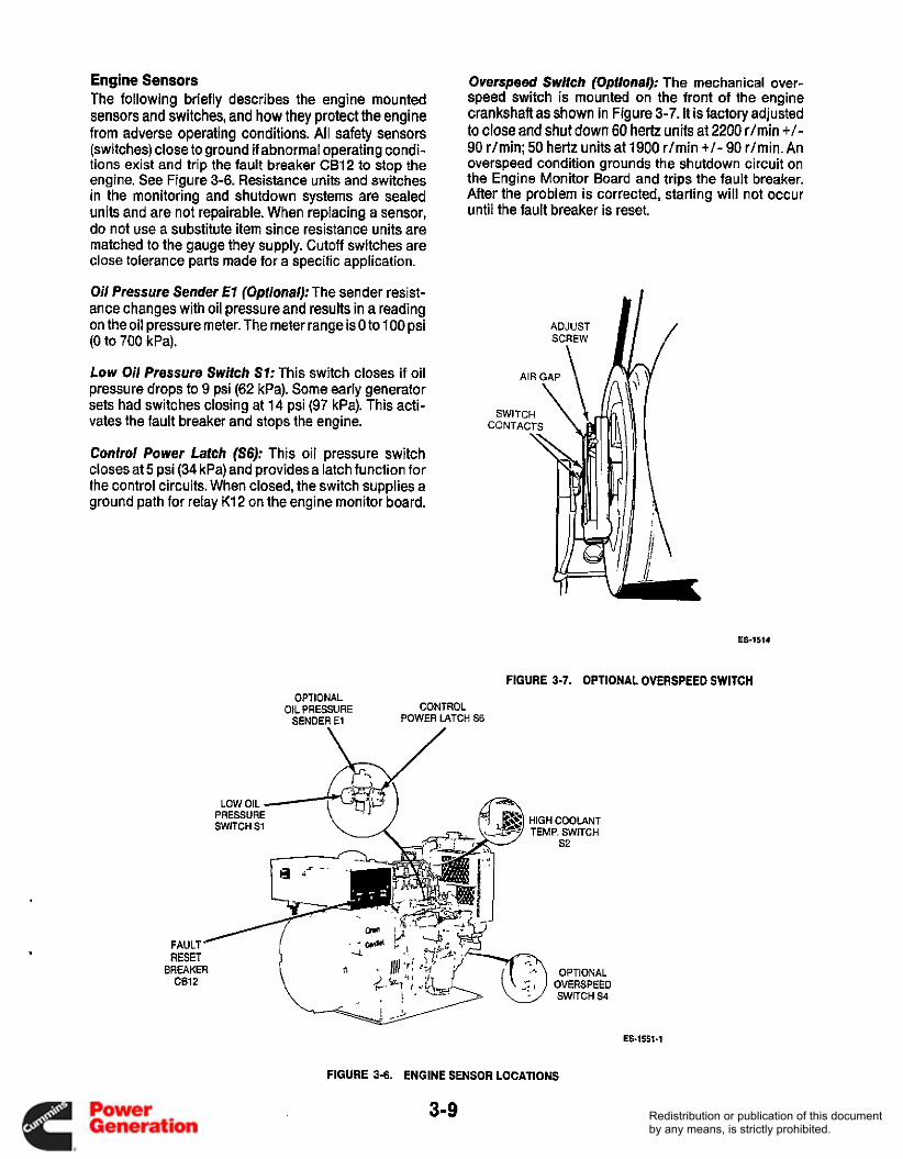
Engine Sensors The following briefly describes the engine mounted sensors and switches, and how they protect the engine from adverse operating conditions. All safety sensors (switches) close to ground if abnormal operating condi- tions exist and trip the fault breaker CB12 to stop the engine. See Figure 3-6. Resistance units and switches in the monitoring and shutdown systems are sealed units and are not repairable. When replacing a sensor, do not use a substitute item since resistance units are matched to the gauge they supply. Cutoff switches are close tolerance parts made for a specific application.
Oil Pressure Sender €7 (Optional): The sender resist- ance changes with oil pressure and results in a reading on the oil pressure meter. The meter range is 0 to 100 psi (0 to 700 kPa).
Low Oil Pressure Switch S7: This switch closes if oil pressure drops to 9 psi (62 kPa). Some early generator sets had switches closing at 14 psi (97 kPa). This acti- vates the fault breaker and stops the engine.
Control Power Latch (S6): This oil pressure switch closes at 5 psi (34 kPa) and provides a latch function for the control circuits. When closed, the switch supplies a ground path for relay K12 on the engine monitor board.
Overspeed Switcl, (Optional’; The mechanical over- speed switch is mounted on the front of the engine crankshaft as shown in Figure 3-7. It is factory adjusted to close and shut down 60 hertz units at 2200 r/min +/- 90 r/min; 50 hertz units at 1900 r/min +/- 90 r/min. An overspeed condition grounds the shutdown circuit on the Engine Monitor Board and trips the fault breaker. After the problem is corrected, starting will not occur until the fault breaker is reset.
S co
1.
ES-1514
FIGURE 3-7. OPTIONAL OVERSPEED SWITCH OPTIONAL
SENDER El POWER LATCH S6 OIL PRESSURE CONTROL
HIGH COOLANT TEMP. SWITCH
FAULT RESET
BREAKER CB12
ES-1551-1
FIGURE 3-6. ENGINE SENSOR LOCATIONS
Redistribution or publication of this documentby any means, is strictly prohibited.

If necessary, the speed trip point can be corrected by turning the adjusting screw, thereby changing the mag- netic air gap. An accurate tachometer or strobotach is needed to check the overspeed trip point after adjust- ment is made. The air gap must not be less than 0.005 inch (0.13 rnm).
Coolant Temperature Sender E2 (0pfional):The resist- ance of the sender unit changes with the engine coolant temperature and causes a reading on the Water Temp meter. The meter range is 100" to 250°F (40" to 121 "C).
High Coolant Temperature Switch S2: This switch closes if the coolant temperature rises to 222°F (1 06"C), activating the fault breaker and stopping the engine.
Control Operation Trouble free operation of the control system should be the major concern of generator set service personnel. Service personnel must thoroughly understand how the controls operate, know how to check for troubles, and know how to make the proper adjustments, replace- ments, or repairs in a reasonable amount of time.
Figure 3-8 shows a typical schematic for the circuits described in the following Starting, Start-Disconnect and Stopping sequences. Relay contact references normally open (NO) and normally closed (NC) refer to position of contacts with the unit at rest (not energized).
Starling Sequence: The engine Preheat switch S12 is held for 10 to 30 seconds (depending upon tempera- ture). This energizes the K13 heater solenoid which closes a NO set of contacts to connect B+ to the glow plugs. After preheat time, the start sequence is initiated by pressing the Start button S1 1 .
Switch S11 contacts B+ to the coil of K14 and (through the A1 1 -K15 contacts and K16 NC contacts) to the Start Solenoid K l l . The coil of K11 is grounded through the pull coil of K1 after K1 is completely pulled in and the pull coil is disconnected from B+. K1 must pull in completely or the engine will not crank.
The closing of K11 contacts connects B+ to the glow plugs and B1 starter solenoid. K14 connects Bt to K1 fuel solenoid, K5 fuel pump, CB12 fault breaker and engine monitor circuits only during starting.
Start-Disconnect Sequence: As the engine starts, latch relay S6 closes and completes the ground circuit through resistor A11-R1 for the K12 power relay. The closing of K12 dual contacts completes the Bt running circuit to CB12 fault circuit breaker.
c
I
CBII( t c I
i
t
i
FIGURE 3-8. TYPICAL CONTROL SCHEMATIC
The start-disconnect circuit provides starter protection. As the generator gains speed and output voltage, the K15 starter protection relay energizes at about 90 volts AC. The A1 1 -K15 NC contacts open and de-energize the K11 start solenoid; the A1 1 -K15 NO contacts close and provide another ground path for K12 through K11 coil similar to S6.
3-1 0 Redistribution or publication of this documentby any means, is strictly prohibited.

A backup start-disconnect circuit is initiated bythe bat- tery charging alternator G1. When DC output at CR11 reaches approximately 6 volts, K16 energizes and opens B+ to the K11 start solenoid. De-energizing K11 disconnects B+ from the starter solenoid to stop crank- ing and eliminate glow plug heating. The K16 relay and CR11 diode are not used in later production generator sets.
Is battery dead?
Stopping Sequence: Placing Si 1 in the Stop position puts B+ on the ground side of K12 power relay. This causes K12 to de-energize and disconnect B+ from CB12, fuel pump E5 and the K1 fuel solenoid. De- energizing K1 shuts off the fuel flow and stops the engine.
Emergency Shutdown: Fault breaker CB12 opens to stop the engine anytime afault sensor closes the circuit to ground. The fault sensors as shown in Figure 3-8 are:
0 S1 low oil pressure 0 S2 high coolant temperature 0 S4 overspeed
Check battery per Checkout [A) and rechargeor replace Check battery charger operation per
CB12 should not be reset for starting until fault is located and corrected.
It K11 does not energize, test per Checkout [HI and replace i f bad. Is battery voltage present at I31 solenoid terminal with S11 in Start position.
Control Troubleshooting The information in this section is divided into three flow charts. Determine the problem and then refer to the appropriate flow chart (A, B, or C) forthe troubleshooting procedures.
Check B+/wiring between K11 and 81 solenoid terminal. Replaceif bad. Check K1 plunger travel for feedom to bottom in solenoid which i s necessary to
nc
A. Engine does not crank. B. Engine cranks but does not start. C. Engine starts but stops after running several seconds.
Before starting a troubleshooting procedure, make a few simple checks that may expose the problem and cut down on troubleshooting time.
Check all modifications, repairs, and replacements performed since the last satisfactory operation of set A loose wire connection could cause problems. An incorrect connection, an opened switch or cir- cuit breaker, or a loose plug-in are all potential problems that can be eliminated by a visual check.
Unless absolutely sure that panel instruments are accurate, use portable test meters for trouble- shooting.
To troubleshoot a problem, start at the upper-lef! corner of chart and answer all questions either YES or NO. Follow the chart until the problem is found, performing reference adjustment or test procedures. Refer to Figures 3-5 through 3-8 for locating control components, leads, terminals and other check points.
FLOW CHART A. ENGINE DOES NOT CRANK Many troubleshooting procedures present hazards fhat can resulr in severe personal injury or death. Only qualifi~servicepersonnel with knowledge of fuels, electricity, andmachinery hazards
should perform service procedures. Review safety precautions on inside cover page.
1 Check battery cables for clean tight connections (re1 Checkout [BI. Check B1 starter solenoid and motor-if bad. repair or replace
jumper oattery cable B+ connection to B1 starter salenoid terminal. Does engine crank?
Yes
Check B+ wiring to S11. and between S11 and K11. Check NC contacts of All-K15 and K16 Replace if I-"+ bad
With S11 in Start position. is battery voltage present between K11 terminal S and ground?
I I I 1
1
3-1 1 I I
Redistribution or publication of this documentby any means, is strictly prohibited.

FLOW CHART B. ENGINE CRANKS BUT DOES NOT START Many troubleshooting procedures present hazards that can result in severe personal injury or death. Only qualifiedservice personnel with knowledge of fuels, electricity, and machinery hazards
should perlorm service procedures. Review safety precautions on inside cover page.
START
Check fuel system: fuel tank level, shut-off valves, fuel lines and connections, fuel filters, fuel pump and injection pump. Okay?
blue-white, and fuel flow steady from fuel return line.
I
Does K1 fuel solenoid and E5 fuel pump energize when S11 is in Start position?
I 1
no
I Is battery B+ applied to glow plug heaters when Preheat Switch is closed? I Check B+ circuit to K14 coil. Test relay K14 per I Checkout [E]. Test K1 fuel solenoid per Checkout [F].
I
no I yes t
I 1 i
I Incorrect fuel? See Operator’s Manual I recommendations. K13 per Checkouts [GI and [E]. Check heater wiring.
FLOW CHART C. ENGINE STARTS BUT STOPS AFTER RUNNING SEVERAL SECONDS. Many troubleshooting procedures present hazards that can result in severe personal injury or death. On/y qualified service personnel with knowledge of fuels, electricity, and machinery hazards
should perform service procedures. Review safety precautions on inside cover page.
START
Check for a possible fault condition. If none, check fault monitors S1 through S4 and fault breaker CB12 for improper wiring.
Is a fault condition indicated by fault breaker CB12 on control panel.
no
Check for closing of S6 power latch switch. If okay. replace engine monitor PC board.
Does latching relay A1 1-K12 energize and contacts close when generator set comes up Ino to operating speed?
yes
. I 1 I 3
I Check all B+ wiring for shorts to ground. Fyes-i Does DC control breaker trip after generator set is started? I
I 1 I I
3-1 2 Redistribution or publication of this documentby any means, is strictly prohibited.

Section 4. Engine Control Service
GENERAL The following component checks are referenced in the Control Troubleshooting flow charts. They are an aid to isolating circuit problems caused by faulty engine con- trol components. Disconnect leads before testing components.
Many troubleshooting procedures JQWAR"GJ present hazards that can result in severe personal injury or deafh. Only qualiiied service personnel with knowledge of fuels, electricity, and machinery hazards should perform service procedures. Review safety precautions on inside cover page.
[AI BATTERY CHECK
Battery electrolyte can cause severe JQWAR"G1 eye damage and burns to the skin. Wear goggles, rubber gloves and a protective apron when working wifh batteries.
Check charge condition of the battery with a hydrome- ter. The electrolyte specific gravity should be about 1.260 for a fully charged battery at 80°F (27OC). If not, add distilled waterto keep electrolyte at proper level and recharge the battery. If battery will not recharge, replace it.
If battery loses excess water, the charge rate may be too high. i f battery state of charge is not maintained, the charge rate may be too low.
BATTERY CABLE CHECK With the starter motor operating, check the voltage drops (1) from the battery negative post (not the cable clamp) to the cylinder block, (2)from the battery positive post to the battery terminal stud on the solenoid. Nor- mally, each of theseshould be lessthan 0.3 volts. If extra long battery cables are used, slightly higher voltage drops may result. Thoroughly clean all connections in any part of the circuit showing excessive voltage drop.
[CI BATTERY CHARGING CHECK
With the engine running, check the DC voltmeter (con- trol option).A 12-voltsystem should be 13.5to 15volts; a 24-volt system should be 27 to 30 volts.
The power source is a belt driven alternator. The charge rateholtage is determined by voltage regulator VR11. On marine sets VR11 is located on the bottom of the control box saddle and it is located inside the control box on land sets.
Improper output may be caused by a loose drive belt, poor terminal connections, broken wires, bad regulator or alternator. Checkout procedures for the regulator and alternator are found in Section 5 of the engine service manual. The charge circuit on RVseries genera- tor sets is protected by a circuit breaker CB13.
If the output voltage is high (over 15 volts), check for loose or corroded voltage regulator leads. If this does not correct the problem, the regulator is probably shorted and should be replaced. With remote start Kubota powered sets, exhibiting overcharging symp- toms, refer to Product Support Bulletin 450.
1.
2.
3.
1.
2.
3.
SOLENOID CHECK
Apply battery positive(B+) to the terminal marked S.
Connect a ground wire to the solenoid mounting bracket. Solenoid should activate.
If the contacts are good, battery voltage should be read between terminal 1 and ground. The voltage drop measured across the contacts should never exceed one volt in circuit application.
RELAY CHECK
Connect relay coil voltage across relay coil termi- nals. Relay should activate if coil is okay.
Connect voltage source to one side of relay contacts.
Connect a voltmeter to other side of relay contact and voltage source. If voltage appears when relay energizes, contact is okay. The voltage reading appears in reverse order when checking normally closed (NC) contacts.
4-1 Redistribution or publication of this documentby any means, is strictly prohibited.

FUEL SOLENOID CHECK SOLENOID CHECK If there is fuel to the injection pump, but no fuel at injection nozzle, the fuel solenoid may be defective.
To check solenoid operation, watch for solenoid actua- tion when B+ is applied (start switch in start or run position). If there is no actuation when B+ is applied, the fuel solenoid must be replaced. When B+ is removed, the solenoid must de-activate.
1. Apply battery positive (B+) to the terminal marked S.
2. Connect a ground wire to the terminal marked 1.
3. Continuity should be read across the two large ter-
Solenoid should activate.
minals while solenoid is activated.
SWITCH CHECK
1. Remove battery B+ cable.
2. Place ohmmeter leads across switch.
3. Open and close switch whileobserving theohmme- ter. A normally open (NO) switch should indicate infinite resistance when open and continuity when closed. A normally closed (NC) switch should indi- cate continuity when closed and infinite resistance when open.
4. Replace switch if defective.
4-2 Redistribution or publication of this documentby any means, is strictly prohibited.

Section 5. Generator/Voltage Regulator
GENERAL DESCRIPTION The YD generator (Figure 5-1) is a four-pole, revolving field, brushless exciter design with drip-proof construc- tion. Single and three phase generators are available for both 50 and 60 hertz models.
The generator rotor is directly coupled to the engine flywheel with a flexible drive disc (engine speed deter- mines generator output voltage and frequency). A cen- trifugal blower on the drive disc circulates generator cooling air which is drawn in through the end bell and discharged through an outlet in the blower end.
DRIVE BLOWER DISC /
A ball bearing in the end bell supports the outer end of the rotor shaft. The end bell is attached with four studs that thread into the generator adapter casting. The brushless exciter stator mounts in the end bell while the exciter rotor and its rotating diode assemblies mount on the generator rotor shaft. Leads F1 (+) and F2 (-)from the exciter stator winding are connected to the output ter- minals of the voltage regulator.
The composite illustration in Figure 5-2 shows the generator output and control/meter leads for the var- ious voltage options. Voltage reconnection diagrams appear in Section 7. Generator/Regu/ator Tests, and in Section 8, Wiring Diagrams.
ROTOR
END BELL
1 BRUSHLESS / EXCITER ROTOR
END BEARING
' ROTATING DIODE
ASSEMBLIES (NOT SHOWN)
\ RUSHL LESS
EXCITER STATOR
XG-1201
FIGURE 5-1. TYPICAL YD SERIES GENERATOR
5-1 Redistribution or publication of this documentby any means, is strictly prohibited.

CONTROL LEADS GENERATOR OPERATION Power generation involves the generator components shown in Figure 5-3. These componentsare italicized in the following text. A permanent magnetembedded in an exciterstatorfield pole begins the voltage build-up pro- cess as the generator set starts. Single-phase AC volt- age, taken from a main stator winding, is connected to the voltage regulator as a reference for regulating the generator output voltage. The regulator DC output is coupled to the exciter stator.
ROTOR MAIN FIELO
,
18 8 518 THREE-PHASE
I I ROTATING
EXCITER STATOR
TO VOLTAGE REGULATOR --
ES-1489.2
# - NOT USED ON 1 0 GENSETS WITH ELECTRONIC REGULATION 5 - NOT USED ON 1 0 GENSETS WITH TRANSFORMER
REGULATION
FIGURE 5-2. SINGLE AND THREE PHASE GENERATOR SCHEMATIC (COMPOSITE)
The exciterrotorproduces three-phase AC voltage that is converted to DC by the full wave rotating rectifier assemblies. The DC voltage excites the rotor main field winding to produce main stator AC for the load.
Generator sets without control panel AC meters are shipped from the factory with the AC output leads separated in the control box. Generator sets with AC meters have the AC output leads wired as specified on the customer’s purchase order to deliver the voltage specified.
EXCTIER ROTOR MAIN FIELD
- -0- DC
-J3- - - -----
I I I I
e3 ROTOR
EXCITER 1 I
MAIN FIELD
- - - - - _ _
VOLTAGE LOAD REGULATOR
ES-1322-2
FIGURE 5-3. EXCITATION BLOCK DIAGRAM
5-2 Redistribution or publication of this documentby any means, is strictly prohibited.

VOLTAGE REGULATOR Thevoltage regulator controls the output of the genera- tor so that a constant voltage is maintained under vary- ing load conditions. There are two types of voltage regu- lators used on these sets: transformer and electronic (solid state). The description and operation of each type is covered separately.
Transformer Voltage Regulator The transformer voltage regulator is standard equip- ment on all single-phase generator sets. It is located inside the generator set control box. A typical trans- former and a schematic showing circuit application is shown in Figure 5-4. The transformer provides a feed- back loop from the output of the generator to the exciter stator.
The number of primary windings and secondary taps will change for 50 hertz and different model applica- tions. See individual model wiring diagrams in the back of this manual.
The transformer primary is connected in series with the generator output leads making it a current boost wind- ing for the secondary. Separate coils in the primary allows the generator to be reconnected for other vol- tages without causing an output voltage unbalance.
The transformer secondary is in the exciter circuit and is connected through a diode bridge. The diode bridge converts AC to DC for the exciter. Thus the exciter DC boost current is dependent upon the primary/load cur- rent.
ES1491
FIGURE 5-4. TYPICAL TRANSFORMER AND CIRCUIT APPLICATION
5-3 Redistribution or publication of this documentby any means, is strictly prohibited.
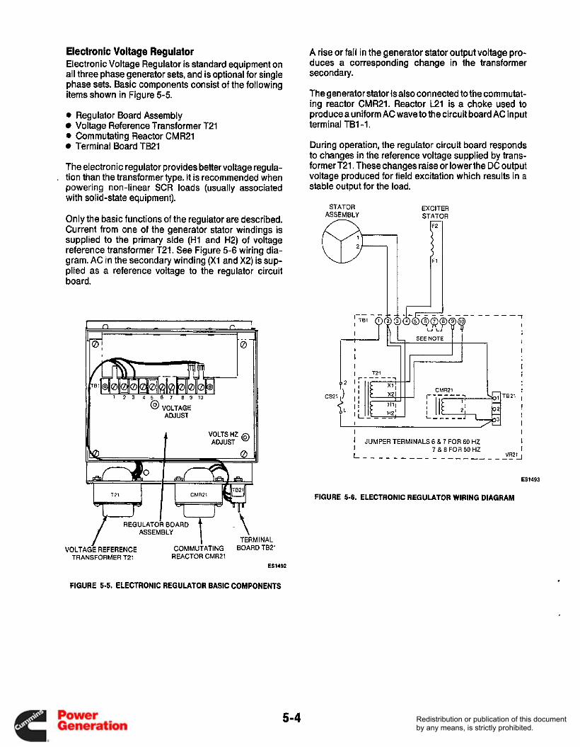
Electronic Voltage Regulator Electronic Voltage Regulator is standard equipment on all three phase generator sets, and is optional for single phase sets. Basic components consist of the following items shown in Figure 5-5.
0 Regulator Board Assembly Voltage Reference Transformer T21
0 Commutating Reactor CMR21 Terminal Board TB21
The electronic regulator provides better voltage regula- , tion than the transformer type. It is recommended when
powering non-linear SCR loads (usually associated with sol id -state equipment).
Only the basic functions of the regulator are described. Current from one of the generator stator windings is supplied to the primary side (H1 and H2) of voltage reference transformer T21. See Figure 5-6 wiring dia- gram. AC in the secondary winding (X1 and X2) is sup- plied as a reference voltage to the regulator circuit board.
@ VOLTAGE ADJUST
TERMINAL VOLTAGE REFERENCE COMMUTATING BOARD TB21
TRANSFORMER T21 REACTOR CMR2l ES1492
A rise or fall in the generator stator output voltage pro- duces a corresponding change in the transformer secondary.
Thegenerator stator isalso connected to thecommutat- ing reactor CMR21. Reactor E 1 is a choke used to producea uniform AC wave to the circuit board AC input terminal TB1-1.
During operation, the regulator circuit board responds to changes in the reference voltage supplied by trans- former T21. These changes raise or lower the DC output voltage produced for field excitation which results in a stable output for the load.
STATOR EXCITER ASSEMBLY STATOR
--1 I
i
I
I 5621 I
! ! I
I I I JUMPER TERMINALS 6 & 7 FOR 60 HZ I I 7 & 8 FOR 50 HZ I L - - - - - - - - - - - - - - - - _ _ _ _ V R 2 1 j
ES1493
FIGURE 5-6. ELECTRONIC REGULATOR WIRING DIAGRAM
FIGURE 5-5. ELECTRONIC REGULATOR BASIC COMPONENTS
5-4 Redistribution or publication of this documentby any means, is strictly prohibited.

.
GENERATOR SERVICE The following sections describe the disassembly and reassembly procedures for the generator.
Generator components are heavy @@@%I and can cause severepersonalinjury if dropped during service. Be careful, keep hands and feet clear during service, and use the recommended service procedures.
Disassembly
1. Disconnect the negative (-) battery cable from the battery to prevent accidental starting of the genera- tor set while servicing.
Accidenfal starting of the set LiiESEl can cause severe personal injury or death. Disconnect the baffery cables, negative (-) lead first, when repairs are made to the engine, controls or generator.
2. Remove cover from the control box and disconnect all stator leads. If control has load circuit breakers, disconnect leads at breaker. If lead markings do not clearly identify reconnection, mark leads with tape.
3. Remove end bell cover and remove field leads F1 and F2.
4. Remove load wiresand flexible conduit from control box.
5. Remove leads from the plug of the DC voltage regu- lator mounted on the bottom of saddle.
6. Remove capscrews securing the control box mounting saddle to the stator. The control box and saddle are removed as an assembly.
7. Pull stator leads through opening in bottom of con- trol box and saddle as they are lifted free from stator. Do not disconnect any engine DC control wires in the control box.
8. Set control box and saddle on top of engine.
9. Remove the end bell stud nuts and slide off the end bell and exciter stator. It may be necessary to pry or jar the assembly loose from the main stator assembly.
10. Use a hoist and safe lifting device (stator handling tongs, nylon lifting strap or chain and lift hooks) to support the stator assembly. A support must be placed under the engine before removing stator from the vibration mounts.
11. Remove stator assembly being careful not to touch or drag it on the rotor. Place stator on its side in the horizontal position.
12. Using a hoist and sling to supportthe rotor, carefully remove the capscrews that attach the drive disc to the engine flywheel (Figure 5-8).
13. Remove the rotor assembly and place upon wood block in the horizontal position. The drive disc and fan should not be resting on anything or distortion may occur.
14. Remove bolts that hold the drive disc and fan to the rotor shaft. Remove bolts holding drive disc to the fan.
15. Use a gear puller to remove the end bearing from the rotor shaft (Figure 5-7).
The end bearing will be dam- - aged if pulled on the outer race. If reused, the bearing musf be pulled on fhe inner race.
16. Clamp the rotor in a fixed position and remove the exciter rotor lock nut.
17. Remove the generator field leads from the exciter rotor and slide the exciter off the rotor shaft.
ES1495
FIGURE 5-7. END BEARING REMOVAL
5-5 Redistribution or publication of this documentby any means, is strictly prohibited.

DRIVE DISK
EXCITER ROTOR
RECTIFIER ASSEMBLIES
6-1158.2
FIGURE 5-8. GENERATOR ASSEMBLY
5-6 Redistribution or publication of this documentby any means, is strictly prohibited.

Reassembly
1. Slide the exciter rotor over the generator shaft and woodruff key. Install the exciter nut and apply torque values shown in Figure 5-9.
2. Connect generator field leads to F1+ and F2- termi- nals on exciter assembly. Torque to values shown.
3. Press the end bearing onto the rotor shaft.
4. Assemble rotor fan and drive disc to the engine flywheel. Use a hoist and sling to support rotor. Be sure the drive disc is assembled with the chamfer on the flywheel side. Apply torque values shown in Figure 5-9.
5. Install air baffle.
6. Using a hoist and safe lifting device, carefully move the stator into position over the rotor. The leads should be in the top position. Apply a thin film of Molykote grease to mating surfaces of end bearing and hole in the end bell.
7. Install the end bell stud bolts through the stator and
8, Install end bell assembly on the stator with the
into the generator adapter.
generator lead opening at top position.
9. Torque end bell stud nuts to 20 ft Ibs (27 Nom).
10. Using a lead hammer tap the end bell at the horizon- tal and vertical to relieve stress. Torque end bell stud nuts.
11. Feed stator and control leads through opening in control box and saddle and secure saddle to the generator.
ASSEMBLE DRIVE DISK WITH CHAMFER THIS SIDE
WOODRUFF
“i SEE DETAIL A 3
(
TORQUETO 130-150 FT LBS (176-203 N*m)
20-22 FT LBS (27-30 Nom)
12. Connect all applicable control leads (Fl, F2, battery charging, etc.) and verify that all connections are secure.
13. Connect leads to the plug of the DC voltage regula- tor mounted on the bottom of saddle. Figure 5-1 0.
14. Install the end bell cover.
15. Connect the stator wires to the load wires.
16. Connect the negative (-) battery cable and test generator operation.
BLUE -
BLACK -
BLUE -
ES1497
FIGURE 5-10. DC REGULATOR PLUG CONNECTIONS
TORQUE TO
(SEE DETAIL 8) (2.6-2.9 NDm)
23-26 INCH LES
FLATWASHER
DETAIL A
DETAIL B
ES-1496-3
FIGURE 5-9. ROTOR ASSEMBLY AND TORQUE VALUES
5-7 Redistribution or publication of this documentby any means, is strictly prohibited.

Redistribution or publication of this documentby any means, is strictly prohibited.

Section 6. Generator/Regulator I- Troubleshooting
GENERAL This section contains service information for single and three phase generator sets with transformer or elec- tronic voltage regulators. Make the following visual checks prior to starting the troubleshooting procedures.
1 I
I
I I
i I
L
0 Check any modification or repair that has been per- formed since the last satisfactory operation of the set to see that they are installed properly.
.
(-011 f i JUMPER TERMINALS 6 & 7 FOR 60 HZ
6,7,& 8 FOR 50 HZ
ELECTRONIC REGULATION
0 Check to see that generator leads are connected correctly. Also check the circuit board connectors. A loose, contaminated, or misplaced wire connec- tion will cause problems that can be detected by close inspection.
Check for an open circuit breaker. If the breaker is open, check for an overloaded circuit and correct load problems before resetting circuit breaker.
. . I I
TRANSFORMER REGULATION
FIGURE 6-1. ELECTRONIC AND TRANSFORMER REGULATION WPlCAL SCHEMATICS)
6-1 Redistribution or publication of this documentby any means, is strictly prohibited.
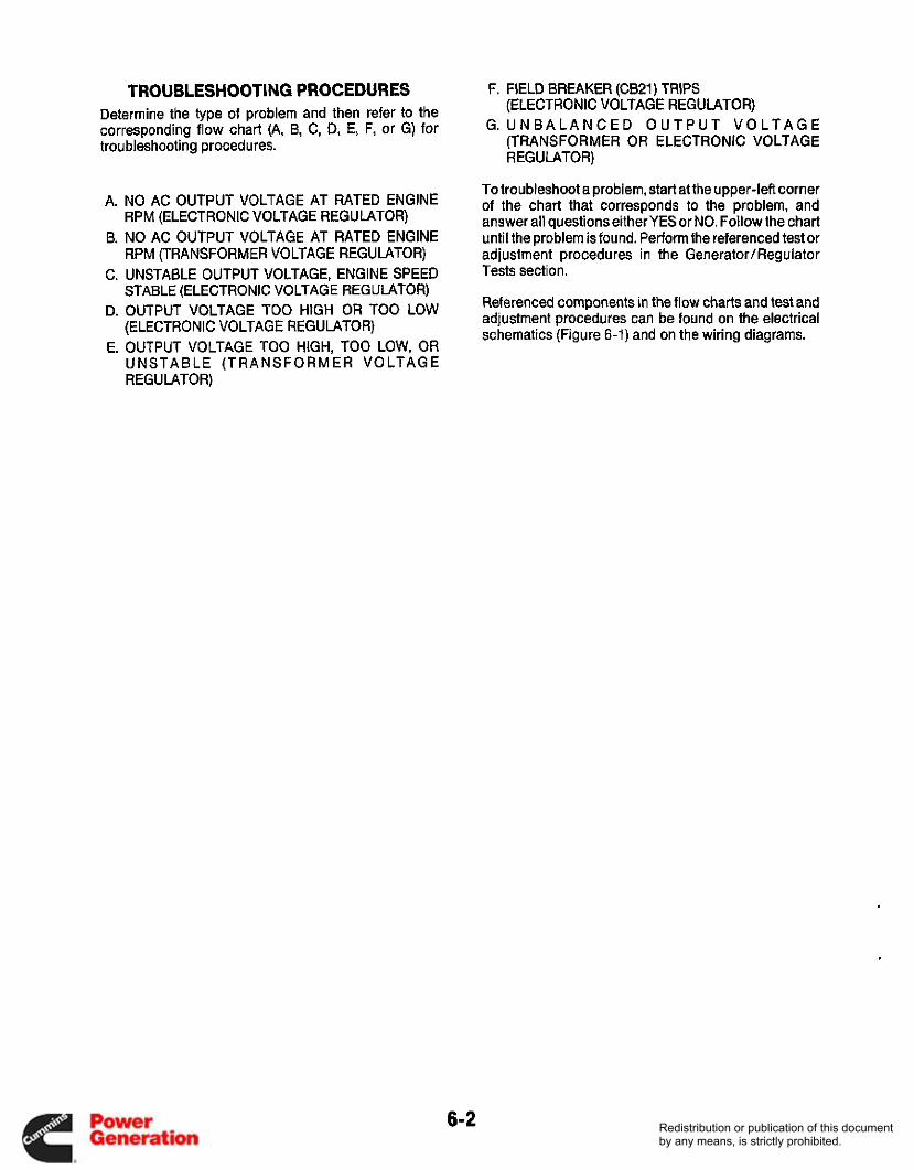
TROUBLESHOOTING PROCEDURES Determine the type of problem and then refer to the corresponding flow chart (A, B, C, D, E, F, or G) for troubleshooting procedures.
A. NO AC OUTPUT VOLTAGE AT RATED ENGINE RPM (ELECTRONIC VOLTAGE REGULATOR)
B. NO AC OUTPUT VOLTAGE AT RATED ENGINE RPM (TRANSFORMER VOLTAGE REGULATOR)
C. UNSTABLE OUTPUT VOLTAGE, ENGINE SPEED STABLE (ELECTRONIC VOLTAGE REGULATOR)
D. OUTPUT VOLTAGE TOO HIGH OR TOO LOW (ELECTRON IC VOLTAGE REGUMTOR)
E. OUTPUT VOLTAGE TOO HIGH, TOO LOW, OR UNSTABLE (TRANSFORMER VOLTAGE REGULATOR)
F. FIELD BREAKER (CB21) TRIPS (ELECTRONIC VOLTAGE REGULATOR)
G. U N B A L A N C E D O U T P U T V O L T A G E (TRANSFORMER OR ELECTRONIC VOLTAGE REGULATOR)
To troubleshoot a problem, start at the upper-left corner of the chart that corresponds to the problem, and answer all questions either YES or NO. Follow the chart until the problem is found. Perform the referenced test or adjustment procedures in the GeneratorIRegulator Tests section.
Referenced components in the flow charts and test and adjustment procedures can be found on the electrical schematics (Figure 6-1) and on the wiring diagrams.
6-2 Redistribution or publication of this documentby any means, is strictly prohibited.
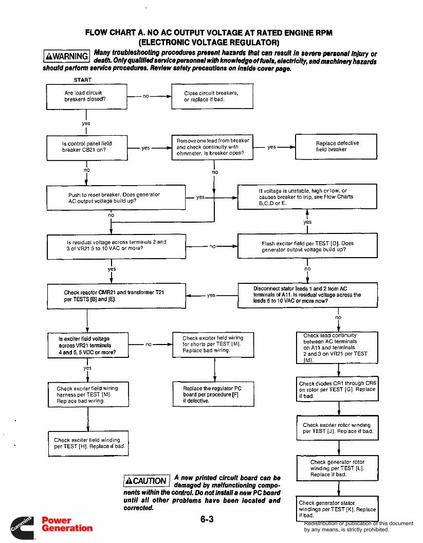
FLOW CHART A. NO AC OUTPUT VOLTAGE AT RATED ENGINE RPM (ELECTRONIC VOLTAGE REGULATOR)
Many troubleshootlng procedures present hazards that can result in severe personal i@v or laWAR"Gl death. Only qualitliedsefflce personnel with knowledge of tuels, electricity, and machinery hazards should perform service procedures. Review safety precautions on inside cover page.
Are load circuit breakers closed?
Close circuit breakers, or replace if bad.
Yes
Remove one lead from breaker and check continuity with ohmmeter. Is breaker open?
Replace defective field breaker
Is control panel field breaker CB21 on?
I no
If voltage is unstable, high or low. or causes breaker to trip, see Flow Charts 6.C.D or E.
Push to reset breaker. Does generator AC output voltage build up?
no
Is residual voltage across terminals 2 and 3 of VR21 5 to 10 VAC or more?
Flash exciter field per TEST [D]. Does generator output voltage build up?
I
Disconnect stator leads 1 and 2 from AC terminals of A l l . Is residual voltage across the Check reactor CMR21 and transformer T21
per TESTS [B] and 14.
for shorts per TEST [MI. Replace bad wiring.
across VR21 terminals 4 and 5,5 VDC or more?
harness per TEST [MI . Replace bad wiring. i f defective.
board per procedure [F]
Check exciter field winding per TEST [HI. Replace if bad. I
A new printed circuit board can be /BcAuTIoNJ damaged by malfunctioning compo- nents within the control. Do not Install a new PC board until all other problems have been located and corrected.
6-3
Check lead continuity between AC terminals on A1 1 and terminals 2 and 3 on VR21 per TEST P I .
I
1
Check diodes CR1 through CR6 on rotor per TEST [GI. Replace i f bad.
I Check exciter rotor winding per TEST [J]. Replace i f bad.
winding per TEST [L]. Replace if bad.
Check generator stator windings per TEST [K] . Replace if bad.
Redistribution or publication of this documentby any means, is strictly prohibited.
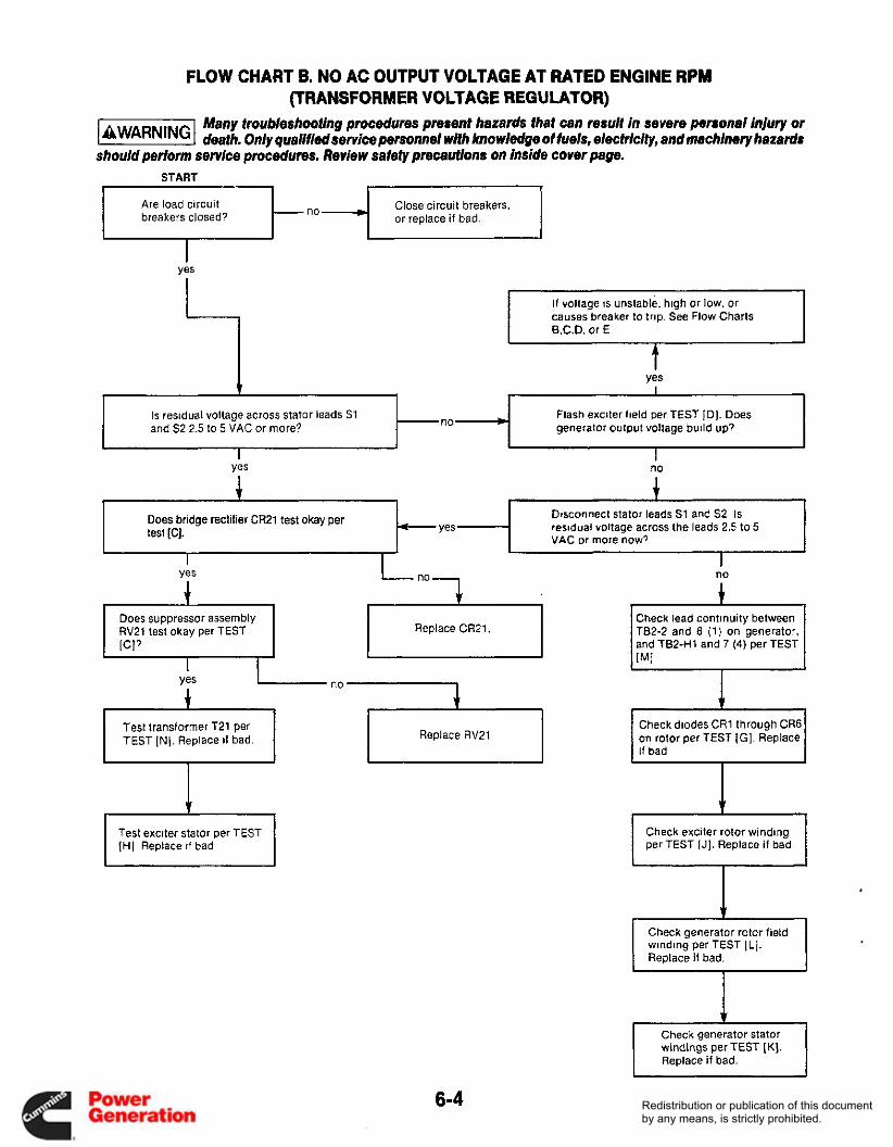
FLOW CHART B. NO AC OUTPUT VOLTAGE AT RATED ENGINE RPM (TRANSFORMER VOLTAGE REGULATOR)
Many froubleshooting procedures present hazards fhaf can result in severe personal injury or 1-1 deafh. Only quallfledservice personnel with knowledge ot fuels, electrlclfy, and machinery hazards should perform service procedures. Review safefy precautions on inside cover page.
START
TEST IN]. Replace i f bad.
Close circuit breakers, or replace if bad. t Are load circuit
breakers closed? I
Heplace HV21
I 1
yes
I f voltage is unstable. high or low. or causes breaker to trip See Flow Charts B.C.D. or E
t Is residual voltage across stator leads S1 and 52 2.5 to 5 VAC or more'?
Flash exciter field per TEST [D]. Does generator output voltage build up7
yes
J no
.c I 1 1 1
Dwonnect stator leads S1 and S2. Is residual voltage across the leads 2.5 to 5 VAC or more now?
Does bridge rectifier CR21 test okay per test IC].
Does suppressor assembly RV21 test okay per TEST Replace CR21.
Check lead continuity between TB2-2 and 8 (1) on generator, and TB2-H1 and 7 (4) per TEST
1 Yes - "0
4 1 ,
I Test exciter stator per TEST I [HI Replace i f bad
1 Check diodes CR1 through CR6 on rotor per TEST [GI. Replace if bad
+ Check exciter rotor winding per TEST [J]. Replace i f bad.
I
6-4 Redistribution or publication of this documentby any means, is strictly prohibited.
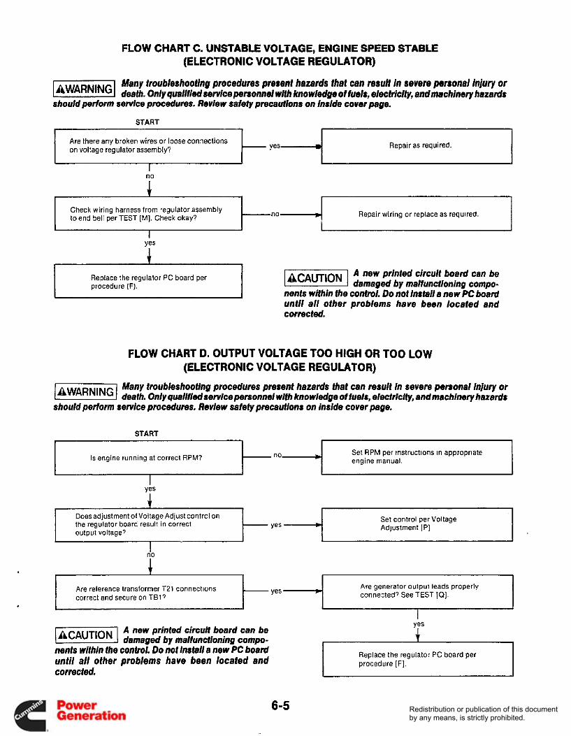
FLOW CHART C. UNSTABLE VOLTAGE, ENGINE SPEED STABLE (ELECTRONIC VOLTAGE REGULATOR)
Are there any broken wires or loose connections on voltage regulator assembly?
Many troubleshooting procedures prerenf hazards that can result in severe personal injury or jawnR"c( death. Only qualifiedservice personnel with knowiedge of fuels, electricity, and machinery hazads should perlorm service procedures. Review safety precautions on inside cover page.
Repair as required.
A
Repair wiring or replace as required. Check wiring harness from regulator assembly to end bell per TEST [MI. Check okay? Ino yes
Replace the regulator PC board per procedure (F). I A new printed circuit board can be k@%!@!l damaged by malfunctioning compo-
nents within the control. Do not Install 8 new PC board until ai/ other problems have been located and corrected.
FLOW CHART D. OUTPUT VOLTAGE TOO HIGH OR TOO LOW (ELECTRONIC VOLTAGE REGULATOR)
Many troubleshoofing procedures present hazards that can result in severe personal injury or death. On/y qualifiedservice personnei wHh knowiedge of fuels, electricity, andmachinery hazards
should perform service procedures. Review safefy precautions on inside cover page.
START I 1 I i
Is engine running at correct RPM? Set RPM per instructions in appropriate t- engine manual.
--I I I
Does adjustment of Voltage Adjust control on the regulator board result in correct output voltage?
Set control per Voltage Adjustment [PI
1 I
I I I 1 t- Are reference transformer T21 connections correct and secure on TI317
Are generator output leads properly connected? See TEST [Q].
~
1 I I
Replace the regulator PC board per procedure [F].
A new printed circuit board can be @!%!@I damaged by malfunctioning compo- nents within the conhi. Do not install a new PC board until all other problems have been located and corrected.
6-5 Redistribution or publication of this documentby any means, is strictly prohibited.

FLOW CHART E. OUTPUT VOLTAGE TOO HIGH, TOO LOW, OR UNSTABLE (TRANSFORMER VOLTAGE REGULATOR)
Apply load to generator and then remove. Is voltage across generator leads S1 and S2 60 VAC 25 percent?
Many iroubieshooting procedures present hazards that can resuit in severe personal injury or b!!!%l death. Only qualified senice personnel witt, knowledge of fuels, eieciricity, and macbimry hazads should perform service procedures. Review safety precautions on inside cover page.
* Test stator assembly per TEST [K]. Replace if bad. no
START
Is engine running stable and at Set r/min per instructions in correct r/min? appropriate engine manual.
1 I
Are there broken wires or loose connections to any AC regulator components?
+ Repair as required.
Test transformer T21 per TEST [N]. Replace if bad.
,
Test exciter stator per TEST [HI Replace if bad,
1 Test rotor assembly per TEST [J]. Replace i f bad.
6-6 Redistribution or publication of this documentby any means, is strictly prohibited.

FLOW CHART F. FIELD BREAKER TRIPS (ELECTRONIC VOLTAGE REGULATOR)
Many troubleshootlng procedures present hazards that cen result in severe personel injury or li5EEEI death. Only qua/ i~i~servicepe~onne/ wm knowledge offue/s, electric&, andmachinery hasanis should pertorm service procedures. Review safety precauHons on inside cover page.
Remove load at generator terminals. lsoutput still unbalanced?
Check for any loose or broken wires or connections on VR21 assembly. Does AC output voltage build up to 150% or
more of rated voltage before breaker trips?
Check lor correct grounding of generator and load.
no
no * Are generator leads connected and grounded properly' See Test [a].
1
Correct as necessary.
I Check exciter stator winding per TEST [HI. Replace if bad. I
Is generator stator winding continuous per TEST [ K ]
Check reference transformer T21 per TEST [E]. Replace i f bad.
Replace stator assembly.
A new printed circuit board can be damaged by malfunctioning compo-
nents within the control. Do not installa new PC board until all other problems have been located and corrected.
Replace the regulator PC board per procedure [F].
FLOW CHART G. UNBALANCED GENERATOR OUTPUT VOLTAGE (TRANSFORMER OR ELECTRONIC VOLTAGE REGULATOR)
Many troubleshooting procedures present hazards that can result in severe pmonal injury or deafh. Only quallfiadservice personnel w/fh knowledge of fuels, electrichy, andmachlnery hazards
should perform service procedures. Review safety precaufions on inside cover page.
1 Check load lor ground faults and correct as necessary.
6-7 Redistribution or publication of this documentby any means, is strictly prohibited.

Redistribution or publication of this documentby any means, is strictly prohibited.

Section 7. Generator/Regulator Tests
GENERAL The following tests and adjustments can be performed without disassembly of the generator. These proce- dures should be used for testing the generator compo- nents and the regulator in conjunction with theTrouble- shooting Flow Charts in the Generator/RegulatorTrouble- shooting section.
Many troubleshooting procedures 1-1 present hazards that can result in severe personal injuq or death. Only qualified service personnel with knowledge of fuels, electricity, and machinery hazards should perform service pro- cedures. Review safety precautions on inside cover page.
[AI TESTING AC RESIDUAL VOLTAGE
Test for residual AC voltage if there is no AC power output from the generator. Check between generator leads 1 and 2 (electronic regulation controls); between S1 and S2 (transformer regulation controls). See Figure 6-1. Residual voltage should be as follows:
Electronic Regulation 5 to 10 VAC minimum. Trans- former Regulation 2.5 to 5 VAC minimum.
TESTING COMMUTATING REACTOR The commutating reactor is shown in Figure 7-1. It is referenced CMR21 on schematics. Only one winding of the reactor (leads 1 and 2) is used. Remove reactor leads from terminal board for testing.
Resistance across 1 and 2 should be 330 to 390 milli- ohms at 77°F (25'C). Resistance between winding and the reactor frame should be infinity.
ES1500
FIGURE 7-1. COMMUTATING REACTOR
[CI TESTING RECTIFIER BRIDGE CR21
AND SUPPRESSOR RV21 The rectifier bridge and suppressor are located within the control box of transformer regulated sets. The bridge contains four diodes as shown in Figure 7-2. They are encapsulated within a hermetically sealed block, and failure of any diode requires replacement of the entire bridge.
Disconnect wires from the bridge prior to testing. Check forward resistance with an ohmmeter on the R x 1 scale; reverse resistance on the R x 1 OKscale. Forward resist- ance should be 6 to 50 ohms, and reverse resistance infinity.
If CR21 is defective, the suppressor RV21 should also be replaced. RV21 should have infinite ohmmeter readings in both directions.
RV21
' ELECTRICAL SCHEMATIC '
ES1501
FIGURE 7-2. RECTIFIER BRIDGE, SUPPRESSOR ASSEMBLY
7-1 Redistribution or publication of this documentby any means, is strictly prohibited.

FLASHING THE FIELD If output voltage does not build up it may be necessary to restore residual magnetism by flashing the field. This requires a 12-volt storage battery, 1 0-amp fuse, momentary-on switch, and diode assembled as shown in Figure 7-3.
(-1 lncorrect flashing procedure can damage the voltage regulator. Do not
keep excitation circuitry connected longer than 5 seconds.
[El TESTING REFERENCE TRANSFORMER
The reference transformer has four leads; two primary marked H1 and H2 and two secondary leads marked X1 and X2. See Figure 7-4. Resistance readings are made with leads disconnected. The resistance of either coil should b e l lOohms+/-10%at77"F (25°C). Resistance between leads and transformer frame should be infinity.
Start the generator set and operate at normal speed. Connect the positive lead to the F1(+) exciter stator lead, and the negative lead to the F2 (-)exciter lead. Close the switch just long enough for the generator output voltage to build up, but not longer than 5 seconds.
Check the output voltage, then shut down the generator set. Restart the generator set and operate at no load. Output voltage must build-up without field flashing. If not, shut down the generator set and perform continuity check of all related wiring. 1 F2- 0
MOMENTARY-ON SWITCH
F1+ 0 12-AMP 300 V
DIODE
10-AMP FUSE
ES-1658.2
FIGURE 7-3 FIELD FLASHING CIRCUIT
(PRIMARY)
"' w HZ
WINDING SCHEMATIC
ES1502
FIGURE 7.4. REFERENCE TRANSFORMER
VOLTAGE REGULATOR VR21 REPLACEMENT
Use the following procedure for replacing the voltage regulator PC board or VR chassis.
1. Stop the generator set and disconnect the starting battery leads, negative (-) lead first.
2. Disconnect (and label if necessary) the wires from voltage regulator. Refer to the AC control wiring diagram.
3. Remove mounting screwsfrom the old voltage regu- lator, then install new regulator.
4. Reconnect wires removed in Step 2 to the proper terminals.
5. Set voltage as outlined in test [PI Voltage Adjustment.
7-2 Redistribution or publication of this documentby any means, is strictly prohibited.

'
TESTING ROTATING RECTIFIERS Two different rectifier assemblies make up the rotating rectifier bridge assembly (Figure 7-5). Using an ohmme- ter, test each CR rectifier using negative (-) and positive (t) polarities. Use the following procedure.
1. Disconnect all leads from assembly to be tested. 2. Connect one ohmmeter test lead to F1+ stud and
connect the other lead to CRl, CR2 and CR3 in turn; record resistance value of each rectifier.
3. Connect one lead to F2- stud and connect other lead to CR4, CR5, and CR6 in turn; record resistance value of each rectifier.
4. Reverse ohmmeter leads from steps 2 and 3 and record resistancevalue of each rectifier F1+ to CR1, CR2 and CR3 and F2- to CR4, CR5 and CR6.
5. All the resistance readings should be high in one test and low in theother test If any reading is high or low in both tests, rectifier assembly is defective.
6. Replace defective rectifier assembly with new iden- tical part.
Use 23 to 26 inch Ibs (2.6 to 2.9 Nom) torque when replacing nuts of F1t and F2-, CR1, CR2, CR3, CR4, CR5 and CR6.
OHMMETER
CR5
CA-1010-9
FIGURE 7-5. TESTING ROTATING RECTIFIERS
[HI TESTING EXCITER STATOR
Test the exciter stator (Figure 7-6) for open or shorted windings and grounds as follows:
Testing for Open or Shorted Windings Use a Wheatstone Bridge or digital ohmmeter for this test. Disconnect F1+ and F2- exciter field leads from terminal block in generator end bell. The resistance between field leads should be 11.16 to 13.64 ohms at 77°F (25°C).
Testing for Grounds Connect a megger or insulation resistance meter that applies 500 VDC or more between either field lead and the exciter stator lamination. Be sure both exciter leads are disconnected from the terminal block. Reading should be 1,000,000 ohms or greater. If not, the exciter stator is questionable and may require removal for oven drying and retest. A shorted stator must be replaced.
F1. F2 LEADS
CA-1010-10
WHEATSTONE BRIDGE OR
DIGITAL OHMMETER
TESTING FOR OPEN OR SHORTED WINDING
F1. F2 STATOR LEADS
LAMINATIONS J
MEGGER OR INSULATION RESISTANCE
METER
TESTING FOR GROUND TO LAMINATION
CA-1010-11
FIGURE 7-6. TESTING EXCITER STATOR
7-3 Redistribution or publication of this documentby any means, is strictly prohibited.

[JI TESTING EXCITER ROTOR
Test the exciter rotor (Figure 7-7) for open or shorted windings or grounds as follows:
Testing for Open or Shorted Windings Use a Wheatstone Bridge or digital ohmmeter for this test. Disconnect main rotor field leads that connect to rotating rectifier assemblies at F1+ and F2-. Disconnect lead wires from diodes CR1 , CR2, CR3, CR4, CR5, and CR6. Test between exciter lead pairs T1 -T2, T2-T3 and T1 -T3. Resistance at 77OF (25OC) should be 486 to 594 milliohms.
EXCITER ROTOR ASSEMBLY
Testing for Grounds Test with an insulation resistance meter or Megger that applies at least 5OOvolts to the test leads. With all gener- ator leads disconnected from rotating rectifiers CR1 through CR6, apply test leads between any CR lead and the rotor laminations. Reading should be 1,000,000 ohms or higher. If not, the exciter rotor is questionable and may require removal for oven drying and retest. A shorted rotor must be replaced.
Use 23 to 26 inch pounds (2.6 to 2.9 Nom) torque when replacing nuts of F1+ and F2- leads, CR1, CR2, CR3, CR4, CR5, and CR6.
R
WHEATSTONE BRIDGE OR
DIGITAL OHMMETER
. .
MEGGER OR INSULATION RESISTANCE
METER
TESTING WINDING FOR GROUNDS TESTING WINDING RESISTANCE
CR3
C W
CONNECTION DIAGRAM ES-1794
FIGURE 7-7. TESTING EXCITER ROTOR
7-4 Redistribution or publication of this documentby any means, is strictly prohibited.

TESTING GENERATOR STATOR Using proper test equipment, check the stator for grounds, opens, and shorts in the windings.
50 Hertz
3.5 DKC/MDKC
Testing for Grounds Some generators have ground connections to the frame. Check wiring diagram. All stator leads must be isolated for testing.
60 Hertz 30 30 10 10 4.OMDKCiMDKC 920 1010 290 380
Use a megger or insulation resistance meter which app- lies 500 VDC or more to the test leads (Figure 7-9). Test each stator winding for short to laminations. A reading less than 1,000,000 ohms indicates a questionable sta- tor. Oven dry the stator and retest.
6.0 DKD
6.5 MDKD
Testing for Open or Shorted Windings Test for continuity between coil leads shown in Figure 7-8; all pairs should have equal resistance. Use an accurate instrument for this test such as a Wheatstone Bridge. Resistance values at 77OF (25OC) are given in Table 7-1.
7.5 DKD 460 498 190 260
8.0 MDKD 460 498 190 260
If a winding is shorted, open or grounded, replace the stator assembly. Before replacing the assembly, check the leads for broken wires or insulation.
TESTING WINDING RESISTANCE - TESTING WINDING FOR GROUNDS -
MEGGER OR 1 1 1 INSULATION RESISTANCE
METER
-- Ill -- 11 / /A y THREE PHASE MODELS
TEST BETWEEN WIRE PAIRS Tl-T4 T7-Tl0 T3-T6 i & @
J - T9-Tl2 T2-TS TB-T11 WHEATSToNE
SINGLE PHASE MODELS TEST BETWEEN WIRE PAIRS
BRIDGE
Tl-T2 T3-T4
ES-1795
FIGURE 7-8. TESTING STATOR WINDINGS
TABLE 7-1. STATOR RESISTANCE VALUES IN MILLIOHMS*
I kWRATlNGANDMODEL I 60HZ I 50Hz 1 60HZ I 50HZ I
*Resistance in ohms @ 77OF (25OC) f10%
7-5 Redistribution or publication of this documentby any means, is strictly prohibited.

[LI TESTING GENERATOR ROTOR
For these tests, use a megger or insulation resistance meter which applies 500VDC or more to the test leads.
Model
Testing for Grounds Check for grounds between each rotor lead and the rotor shaft, Figure 7-9. Use a Megger or insulation resistance meter which applies 500 VDC or more at the test leads. Perform test as follows:
Ohms Resistance*
Remove rotor leads F1+ and F2- from the rotating rectifier assemblies. Connect test leads between F1 t and rotor shaft, then between F2- and rotor shaft. Meter should register 1,000,000 ohms or greater. If less than 1,000,000 ohms, rotor is questionable. Oven dry the rotor and retest. Replace a grounded rotor with a new identical part.
DKC/ M DKC 1 DKD/MDKD
Testing for Open or Shorted Windings Perform this test with an accurate meter such as a digital ohmmeter.
2.50 2.82
1. Remove rotor leads F1+ and F2- from rotating recti-
2. Using ohmmeter, check resistance between F1 and fier assemblies.
F2 leads, Figure 7-10.
MEGGER OR INSULATION RESISTANCE
METER
CA-1010-12
TESTING WINDING FOR GROUNDS
FIGURE 7-9. TESTING ROTOR FOR GROUNDS
DIGITAL f l --_ OHMMETER
MAIN ROTOR LEADS F1+, F2-
CA-1010-8 -
TESTING WINDING RESISTANCE
FIGURE 7-10. TESTING ROTOR FOR AN OPEN CIRCUIT
*Resistance in ohms @ 7 7 O F (25OC) f10%
7-6 Redistribution or publication of this documentby any means, is strictly prohibited.

[MI
31 5-0572
.003 f .0005
.003 f .0005 N.A. N.A. N.A.
1.15 -f .01 1.11 .01 .019 * .01
a WIRING HARNESS CHECK
31 5-0582 315-0583
.007 f .0005 -007 f .0005 .003 f .0005
1.44 * .1 1.33 f .1 1.21 f .1 .04 f .01 .02 * .01
.004 f .0005
.004 f .OM5
.002 f .0005 1.37 f .1 1.35 -f .1 1.24 k .1 .04 f -01 .02 f .01
H1 THROUGH H4
Carefully check wiring harness as follows:
1. Inspect all wires for breaks, loose connections, and reversed connections. Refer to applicable wiring diagram.
2. Remove wires from terminals at each end and with an ohmmeter, check each wire end to end for conti- nuity or opens.
3. Using an ohmmeter, check each wire to other wires and to ground for possible shorts or insulation breaks under areas covered by wrapping material.
4. Reconnect or replace wires/ harness according to applicable wiring diagram.
TEST1 NG REGULATING TRANSFORMER T21
TRANSFORMER WINDING
SCHEMATIC
x2 H2
x3
H4 PRIMARY SECONDARY
ES-1510
FIGURE 7-11. TYPICAL REGULATING TRANSFORMER
Regulating transformer 121 is used only on single phase generators. It consists of a multi-coil primary and a multi-tapped secondary. Figure 7-1 1 shows a typical transformer. Some transformers may have up to three coils in the primary and six taps on the secondary.
DC resistance of windings at 77OF (25OC) are shown in Table 7-3. Resistance between primary and secondary and the transformer frame should be over 100,000 ohms when measured with a megger or insulation meter.
TABLE 7-3. TRANSFORMER RESISTANCE VALUES IN OHMS
Primary H1 -H2
Secondary X1 -X6 x1 -x5 x1 -x4 x1 -x3 x1 -x2
H3-H4 H5-H6
315-0571
.007 f .0005
.007 f .OM5 N.A. N.A. N.A.
1.29 f -01 1.24 f .01 .019 f .01
N.A. (Not applicable)
7-7 Redistribution or publication of this documentby any means, is strictly prohibited.

[PI VOLTAGE ADJUSTMENT
This section supplies information for adjusting the trans- former and electronic regulators. When checking output voltage, be sure the generator set has stabilized and is running at the correct speed (frequency). Adjusting the transformer regulator is done with the set stopped. The electronic regulator is adjusted with the set running.
Accidental starting of the set can l3iEGEI cause severe personal injury or death. Disconnectbofh battery cables, negative (-1 cable first, when repairs are made to the engine, controls, or generator.
Transformer Voltage Regulator The transformer regulator circuit supplies a feedback voltage (dependent on load) to the exciter stator. Voltage adjustment is made by changing tap connections on the transformer. When replacement is necessary, install leads to the same terminals on the new transformer. To change voltage, refer to the model wiring diagram or the generator reconnection diagrams in Test [Q].
Electronic Voltage Regulator
Contact with high voltage can cause severe personal injury or death. Do
not touch any exposed wiring or components with any pari of the body, clothing, tool or jewelry. Do nor use non-insulated tools inside the control. Stand on an insulating mat or dry wood platform when the control doors are open.
With the generator set running, set the Voltage Adjust potentiometer on the regulator board assembly for cor- rect voltage. See Figure 7-12.
Do not adjust the other potentiometer l2iCEEI po/ts/Hz Adjust) as it can be impos- sible to reset for proper operation. It is factory set using special calibration equipment.
-
ES-1388
FIGURE 7-12. ELECTRONIC REGULATOR BOARD
[Ql RECONNECTION
Generator reconnection is dependent upon the name- plate code. Figure 7-13 shows reconnection possibilities. Information is also found on the individual model wiring diagrams in Section 8 of this manual.
7-8 Redistribution or publication of this documentby any means, is strictly prohibited.

Transformer Regulation
. . . . . . . . . . . . . . . . . . . . . . . . . . . . . .
, -: I -
_ . . .- - -. .... a .
. . e . . . . . . . . . . - .. . .
..-: - ...... . . . -: ........ -. . e .
... 5 -: - _ .
. . . . . . . ?;,. . -
. . . . . . . . . ._ .: . . . e . ..... ..
60 Hz
120-240 V A C
---;-*- L ' LI
* L 2
H4 H3 H4 H3 RECONNECTION T3Tl TZT4
RECONNECTION DIAGRAM
SHOWN FOR 120 240 V 60 H Z 11Sf230 V 50 H2 ----
LYE J
t CWl
To Adjust OUtpLit Voltage. Move Taps on T21 According to Following Charts
LI L2
DKD ,MOUE
I
I
5rC uw:
1:& I 1 2 , I 4
I IO 14
NOTES
I IN ALL VOLTAGE CONNECTIONSl5OAflD60H~~ LEAVE TIPNOT4
2FDRM)Hz USES2LEADlFROMCENIDN TAPSXI-2
3 FDR50Hz USES2LEADlFROMGENIONTAPS XI.3
D FOR IIOI2X)VANDllOVCONNECT H2 TO H6.
CONNECTEDTOHI ANDH4 RESPECTIVELY
I 4 l A P S I USE 1XLEADONTAPSX3-4
16TAPS1 USETXLEADONTAPS 14.6
FOo9 l l O V COHNECTH5 T O T I l L I l A H D H 3 T D T Z l L 2 1 FOR 11012ZOV USE H I FORLIINOH3FORLZITZ ANOT3AREGHO
Electronic Regulation .
- Codes IC 60 HI Code 53C SO HI - mw ~ a m - m w
. . . . . ... . a,.
. **
. . . _- . . . .*
. 5Qnz : : 5QHL ., . mw .... . . . .... ... ... .- * .- A .. a 1 .
. -.. - . . - - . . . M W . . . - .. .. ..
I..
FIGURE 7-13. GENERATOR RECONNECTION DIAGRAMS
7-9 Redistribution or publication of this documentby any means, is strictly prohibited.

Redistribution or publication of this documentby any means, is strictly prohibited.
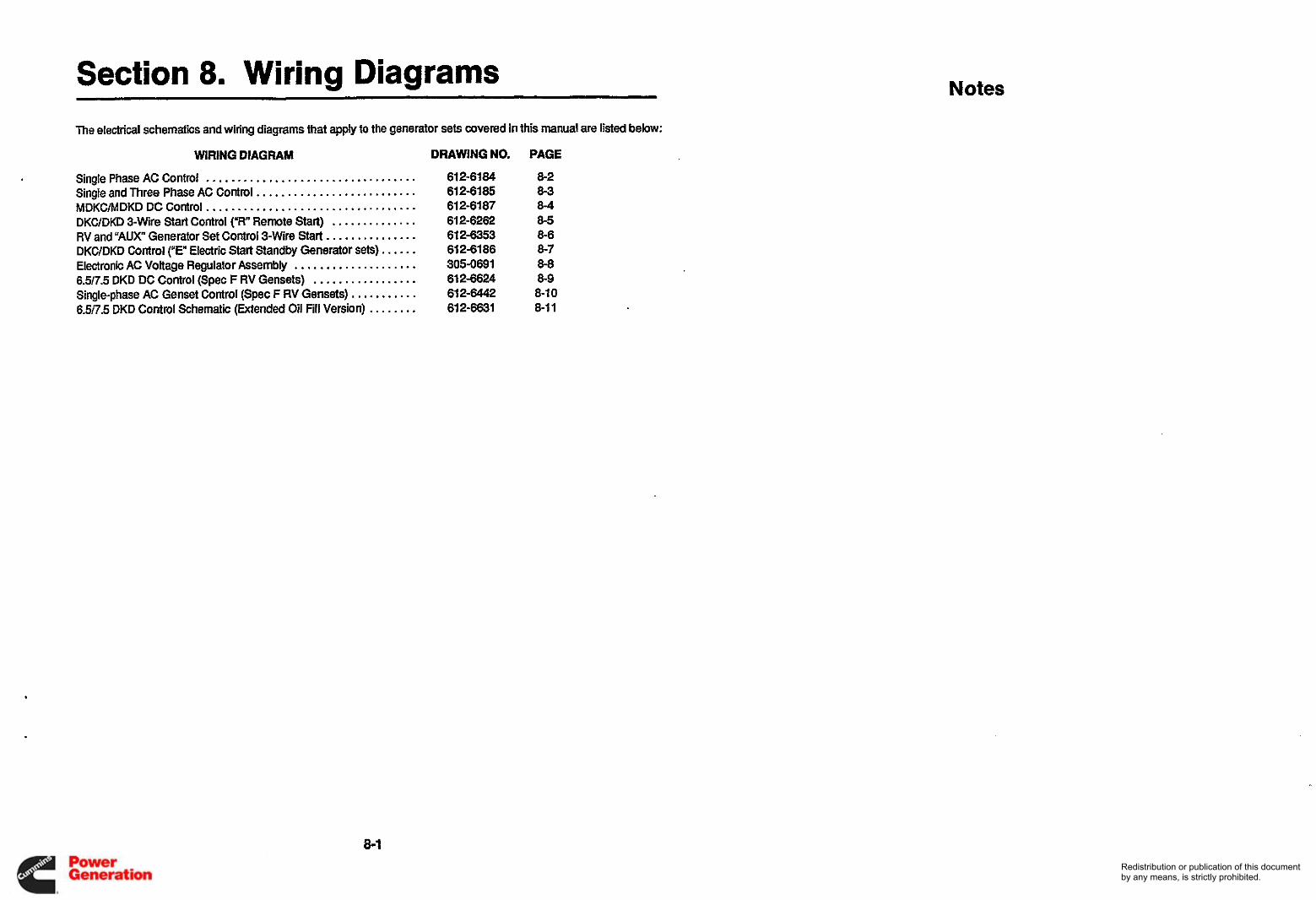
Section 8 . Wiring Diagrams The electrical schematics and wiring diagrams that apply to the generator sets covered in this manual are listed below:
WIRING DIAGRAM DRAWING NO . PAGE
Single Phase AC Control .................................. 61 2-61 84 61 2-61 85
MDKC/MDKD DC Control .................................. 61 2-61 87 DKC/DKD 3-Wire Start Control ("R" Remote Start) .............. 61 2-6262 RV and "AUX" Generator Set Control 3-wire Start ............... 61 2-6353 DKC/DKD Control ("E" Electric Start Standby Generator sets) ...... 61 2-61 86
305-0691 65/73 DKD DC Control (Spec F RV Gensets) ................. 61 2-6624 Single-phase AC Genset Control (Spec F RV Gensets) 61 2-6442 6 W . 5 DKD Control Schematic (Extended Oil Fill Version) 612-6631
Single and Three Phase AC Control ..........................
Electronic AC Voltage Regulator Assembly .................... ...........
........
Notes
8-2 8-3 8-4 8-5 8-6 8-7 8-8 8-9 8-10 8-11
8-1 Redistribution or publication of this documentby any means, is strictly prohibited.

AC SCHEMATIC SINGLE PHASE TRANSFORMER REG
EXCITER
\G21
I I I A l l ,-l-l-,
IAC AC I I I I I
I I
I I I I L---..J
I ! I
I 1- 1 1 L2 LI
NOTED TO ADJUST OvlpvT VOLTAGE. WVETLR MI TZI ACCOROlffi TO TABLES.
1 IN K L WLTAGE COHHECllOHS~5OOAHOW H).LEAVE TI ANDT4
Z F O R 6OtW USE SZ L E L D t W GENI Cn Tu19 X I 4 CWNECTED TO HI AN0 H4 REWXTlVEJY.
(.)TIPS) USE ?X L U D O H T B X3-4
(6 TAR?) USE Tx LEAD On T Y S X4-6 a FOR I lOlZZOV uy) l lOV CCnNECT HZ TO tt6.
LRR 115/230V*ND I I J V INSULATE H I AND H 6 (HOT USED) c . M 120/240V &IO 12OV CDlHECT HZ TO HS.
DE-EI(ERGISD posnii.
M llOV CONNECT HJ TOTS(LI1 A W H 3 TOTZ(L-2). FOR 110122OV USE H 5 FOR LI ANOH3 FOR LZ(TZAH)T3AILGRD)
RR 12OV CWHHECT H6 TO T3 t LI' H I T O R (LZJ FOR126/24OV USE Hb FORLI AH) H3FCRLZ~Z'MDT3APFGRD)
4. UNLESS OTHER NOTED ALL COIPOHENTS ARE sim m M
J. & A l l DASHED CWNECTIOM llwEs IKnUm ON-xR,.-S3CRMoDLLS m a USED. MILY. @ INSUIATE LuDl On -%E. -5XE YODELS.
I LO CB
W 0
W n
B
SOHI (-021 IM,110/220V I I I 5 , I I m v 1120.120/240v
DKC OKC
L -I. I I
FROM PANEL (REAR VIEW)
x4 .
CONTROL BOX(DC SECTION) I
SINGLE PHASE AC CONTROL
8-2 Redistribution or publication of this documentby any means, is strictly prohibited.

F-": ' 8 .m 6 I 5 I 4 I 3 I 2 1 - ._ . 612-6185 101 -
AC WIRING DIAERCIM - ELECTRONlC R'S2ULATION 18, 518, 36,532 m t f T EXCITER NOTES '
I. CUT LEADS 384 mtm ~ 2 1 . n i ~ 9
ARE SHOWN m DE-ENERGIZED FWMIN.
W A R E NCr rwm.
2s 2s 2s
2. UNLESS O M R W I S E NOTED.ALL COMPONENTS
F I 3. DASHED LINES HDICAlE CONNECTrONS
WHEN USED.
ONLY. FOR-3CE,-53CE;18E,-5l8E MODELS CONNECT LEADS 182 DIRECTLY TO VR21.
WILL NOT BE USED. INSULATE ANDLEAVE IN CONTROL BOX.
-EN TERMINALS 788 FOR 50 Hz.(-02)
@ 4 A l l CONNECTIONS ON-3CR;J?ICR,-I8R;SI8R H D E L S
5. mR 10 GENERATOR r 3 c ANDBC) LEADS SIAN~SZ
A 6. JUMPER TERMINALS 6a.7 FOR 60 Hr.(-OI).ADD JUMPER
W SEE E RECONNECTION DIAGRAM k
FRONT PANEL (REAR VIEW 1
I I 18 8 518
COMROL BOX (AC SECTION) y-- VR21
J r
I I 1 I
I
1 I -- * -- I---
AC SCHEMATiC - ELECTRGXIC REG VOLTAGE CODES (IBBS!3,3C&5X)
r .. RECONNECTION MAGRAM
I I L2 13
SINGLE AND THREE PHASE AC CONTROL
8-3 Redistribution or publication of this documentby any means, is strictly prohibited.

SCH E MAT IC
--- -r i :
i I . J
A l l K I L
REMOTE
I I !-
IA CB12 -! I- PANEL INSERT
-'I I
CC'NTROL -i OF JS- FEMALE CONNECTOR R E M VIEW
I I
HRI I +--
-1 E--- - I I
I
VIEW OF WIRING FOR VRI I PLUG j- BTI
MDKCIMDKD DC CONTROL
8-4 Redistribution or publication of this documentby any means, is strictly prohibited.

SCHEMATIC
CB'? Y! I I
I
+ I l a I MI4 I '-----I
r- I I r-----. - . - 1 /
AI I I REAR VIEW OF REMOTE PAREL I I-----
CBl l (
t HRI -
~ I I
aLuc
KLLW
I VIEW OF WIRING FOR VHll PLUG
ND L -
W" I" Cupl - . l . . r
I REAR VIEW OF FRONT PANEL
DKC/DKD &WIRE START CONTROL (,,R' REMOTE START)
8-5 Redistribution or publication of this documentby any means, is strictly prohibited.

I
612-6353 1.1 WIRING DIAGRAM LuW, -. - --
I f
--- REAR VIEW $E*--
I
___f I
PANEL INSERT -
BLACK (ELLOW
GREEN I I
VIEW OF WIRING FOR VRll PLUG
RED
r---- - -1
I W
I -J
"&,-I?;,-
&I L U C
BT t I '1III-
RV AND "AUX' GENERATOR SET CONTROL, 3-WIRE START
8-6 Redistribution or publication of this documentby any means, is strictly prohibited.

SI I
VIEWOF WIRING FOR VRll PLUG
t
RI
I
CB12
Llwl
I
REAR VIEW W-WT PANEL
_ _ _ _ _ .
DKClDKD CONTROL (“E” ELECTRIC START STANDBY GENERATOR SEIS)
8-7 Redistribution or publication of this documentby any means, is strictly prohibited.
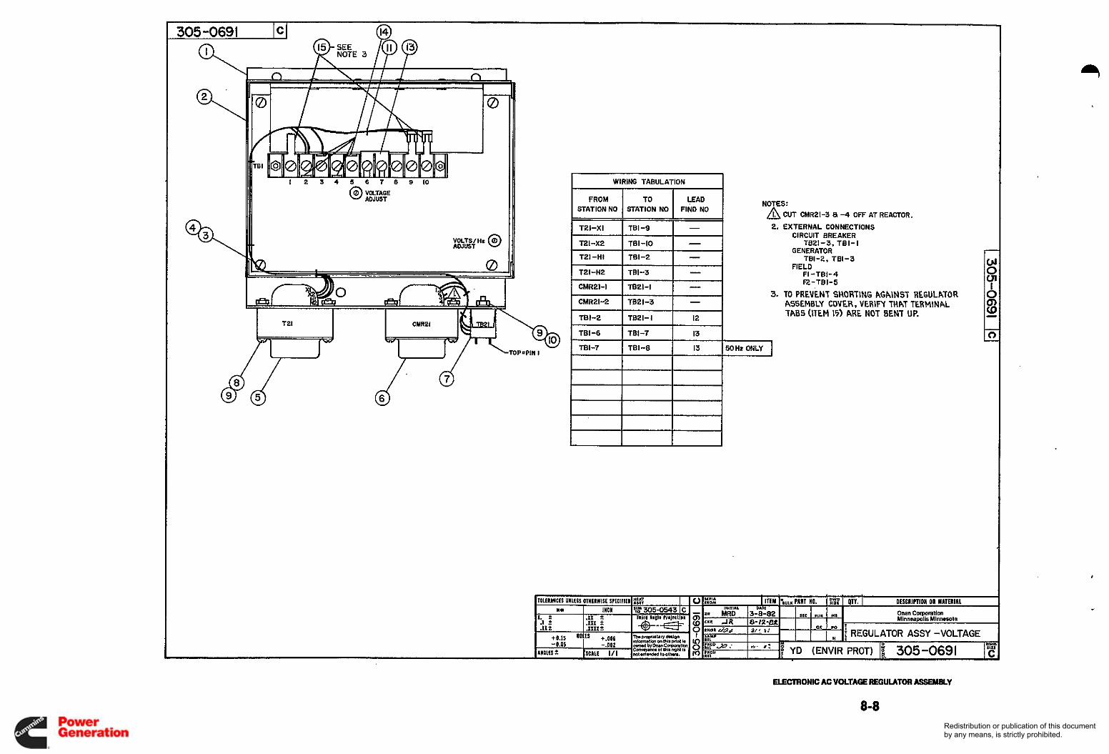
0 VOLTAGE 0 ADJUST
VOLTWHr @ ADJUST
WIRING TABULATION
FROM TO F A D STATION NO STATION NO FIND NO
I T21-XI I TBI-9 I - I TZI-XZ 781-10 - TLI-HI TBI-2 - TZI-HZ TBI-3 - CMR21-I TB21-I - CMR21-2 TB21-3
TB 1-2 TB21- I 12
-
NOTES: A CUT CMR21-3 a -4 OFF AT REACTOR. 2. EXTERNAL CONNECTIONS
CIRCUIT BREAKER TB21-3, TBI- l
GENERATOR TBI-2, TBI-3
FIELD FI-TBI-4 FZ-TBI-5
3. TO PREVENT SHORTING AGAINST REGULATOR ASSEMBLY COVER, VERIFY THAT TERMINAL TABS (ITEM 15) ARE NOT BENT UP.
I
ELECTRONIC AC VOLTAGE REGULATOR ASSEMWY
8-8 Redistribution or publication of this documentby any means, is strictly prohibited.
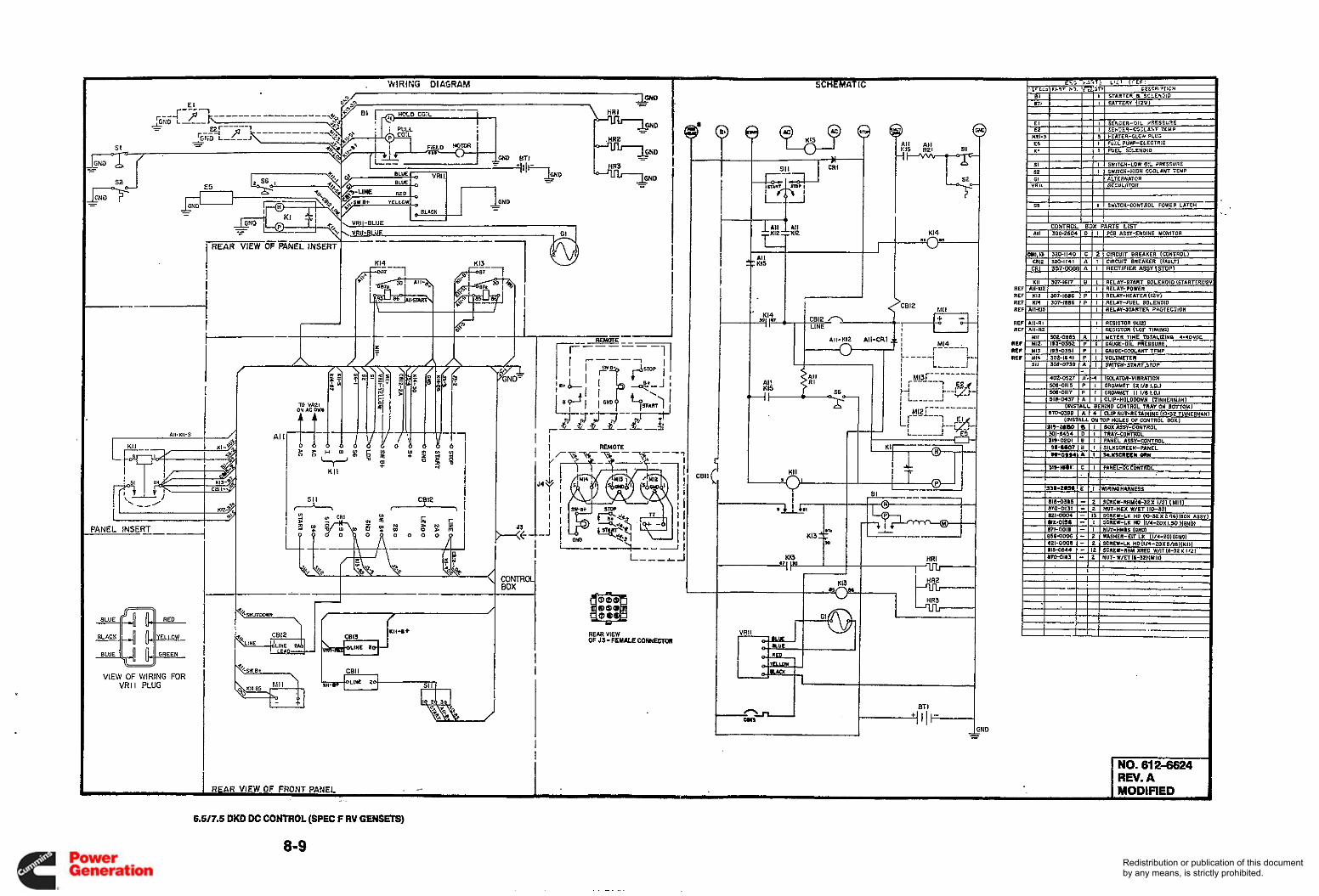
._ K14
v scn15
_I 1 . I t
All-KII-5 I
1 I I !
I I I I I J
I
I i i d KI I
I s : ' I A I
PANEL INSERT
I----,
CONlRWl BOX I I I
1 I 3w BLACK 4 a- YELLOW OF REM 53-FEMALECOWECTOII VIEW
BLUE l u GREEN
VIEW OF WIRING FOR VRI I PLUG
I - I MODIFIED , RFAR VIEW OF FRONT PANEL . - - -.
6.5/7.5 DKD DC CONTROL (SPEC F RV GENSEXS)
8-9 Redistribution or publication of this documentby any means, is strictly prohibited.
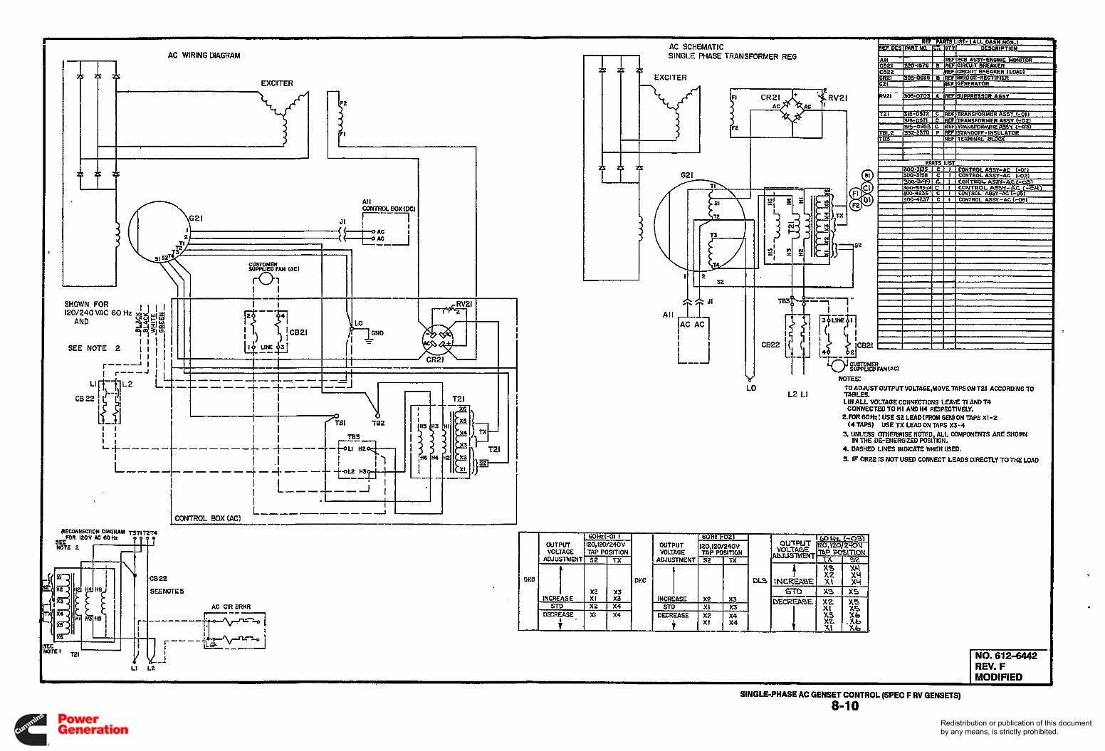
AC SCHEMATIC AC WIRING DIAGRAM m t
SINGLE PI-IASE TRANSFORMER REG
EXCITER I I l l IxH-0703 I A I R E F l S U P P R F m ASSY RV21
I n A \G21 JI f I
I
i U
All
2 s2 I ' I I I I J
I 1 1 I l l
CUSTOMER SUPPLIED FAN (AC)
W E S : TO AOJUST OUTPUTVOLTAGE,MOVE TAPSON 121 ACCORDING TO
LIN ALL VOLTAGE CONNECTIONS LEA'/€ ll AND 14
Z F O R ~ ~ H Z : U S E S2LEAD(FROMGEN)ONTAPSXI-2
3. UNLESS OTHERWISE NOTED ALL COMPONENTS ARE SHOWN IN M E UE-ENERGIZED POSIiION.
4. DASHED LINES INOICAE WHEN USU). (I. IF CE22 IS NOT USED CONNECT LEADS DIRECTLY TOTHE LOAD
L2 LI TABCES. LO
CONNECTED TO HI AND H4 RESPECTIVELY.
(4TAFS) USETX LEAqONTAPS X3-4
1 MODIFIED
SINGLE-PHASE AC GENSET CONTROL (SPEC F RV GENSETS)
8-1 0 Redistribution or publication of this documentby any means, is strictly prohibited.

M= WIRING DIAGRAM El i
d
SI I!
0 JI FRONT VIEU
SCHEMATIC
K13 I
cB12 - I A l l ' CRI
SI b 1- M I A l l ti6 R2
s2
K14
I%--*)
CONTROL BOX PARTS LIST -01. -02 I737 1 0 1 1 I . 1-M
I ! I I I I , I
NO. 612-6631 REV. A I MODIFIED __
6.5!73 kW DKD CONTROL SCHEMATIC (EXTENDED OIL FILL VERSION)
8-1 I Redistribution or publication of this documentby any means, is strictly prohibited.

Redistribution or publication of this documentby any means, is strictly prohibited.

Redistribution or publication of this documentby any means, is strictly prohibited.

Cummins Power Generation 1400 73rd Avenue N.E. Minneapolis, MN 55432
Fax: 763-574-8087 763-574-5000
Cummins and Onan are registered trademark of Cummins Inc. Redistribution or publication of this documentby any means, is strictly prohibited.


![DKD and ISO calibration of temperature sensors. Fluid ...3-point DKD calibration ZC0013 Measurement points [ C] 65, 85,123 Measurement uncertainty [K] 0.1 5-point DKD calibration 20,](https://static.fdocuments.us/doc/165x107/611b11cf3846564b00111d67/dkd-and-iso-calibration-of-temperature-sensors-fluid-3-point-dkd-calibration.jpg)


