ON THE SUBJECT OF HIGH-SPEED...
44
ON THE SUBJECT OF HIGH-SPEED MONOHULLS By Daniel Savitsky * Presented to the Greek Section Of the Society Of Naval Architects and Marine Engineers Athens, Greece. October 2, 2003 Abstract This presentation discusses the hydrodynamic evolution of the three basic monohull forms; describes their upper limits of non-dimensional speeds; defines their relative transport efficiencies and useful load fractions; and finally defines the geometric and operational characteristics of a unique displacement type hull that has a maximum speed of 50 knots ,a transport efficiency nearly twice that of existing 50 knot craft and meets the suggested operational requirements for a high-speed sea- lift ship. Most of this presentation is based upon first principles of naval architecture. Also, since high speed and high sea state usually have an adversarial relationship, the results of recent model studies at the Davidson Laboratory, Stevens Institute of Technology, will be presented that demonstrate the beneficial effects of active controls in making these conditions compatible. Again, this discussion will be based upon first principles of dynamics. Introduction The title of this presentation should immediately raise at least two questions ---first, what is meant by high- speed? Second, is why restrict this talk to monohulls?. I’ll try to answer these questions. I recently became aware of a study entitled “Small, High Speed Vessels”. My first reaction was that this was a study of small, fast, planing recreational craft or racing boats. I soon discovered that this was not at all the case since the paper dealt with relatively large boats having displacements greater that 500 tons and “high” speeds defined to be approximately 25-30 knots –clearly not what conventional wisdom would have lead me to believe, Perhaps I shouldn’t have been surprised since the title did refer to “vessels” which are usually larger than planing hulls. In fact, these were semi- displacement vessels whose hulls shapes are distinctly different than planing hull forms. It is usually accepted that the high speed of semi-displacement hulls or displacement hulls are considered to be low- speed for planng hulls. This conclusion, however, is not necessarily absolute but raises the question—what is meant by high speed? While it is usually accepted that, the greater the boat speed, the greater the cost to buy and operate, and the smaller the payload- it will be shown that the same value of high speed can be designed into all monohull hull shapes, (not necessarily just small vessels) without compromising their hydrodynamic efficiency, provided that their dimensions are appropriately selected. * Professor Emeritus, Davidson Laboratory, Stevens Institute of Technology
-
Upload
dinhnguyet -
Category
Documents
-
view
217 -
download
2
Transcript of ON THE SUBJECT OF HIGH-SPEED...
ON THE SUBJECT OF HIGH-SPEED MONOHULLS By Daniel Savitsky * Presented to the Greek Section Of the Society Of Naval Architects and Marine Engineers Athens, Greece. October 2, 2003 Abstract This presentation discusses the hydrodynamic evolution of the three basic monohull forms; describes their upper limits of non-dimensional speeds; defines their relative transport efficiencies and useful load fractions; and finally defines the geometric and operational characteristics of a unique displacement type hull that has a maximum speed of 50 knots ,a transport efficiency nearly twice that of existing 50 knot craft and meets the suggested operational requirements for a high-speed sea- lift ship. Most of this presentation is based upon first principles of naval architecture. Also, since high speed and high sea state usually have an adversarial relationship, the results of recent model studies at the Davidson Laboratory, Stevens Institute of Technology, will be presented that demonstrate the beneficial effects of active controls in making these conditions compatible. Again, this discussion will be based upon first principles of dynamics. Introduction The title of this presentation should immediately raise at least two questions ---first, what is meant by high- speed? Second, is why restrict this talk to monohulls?. I’ll try to answer these questions. I recently became aware of a study entitled “Small, High Speed Vessels”. My first reaction was that this was a study of small, fast, planing recreational craft or racing boats. I soon discovered that this was not at all the case since the paper dealt with relatively large boats having displacements greater that 500 tons and “high” speeds defined to be approximately 25-30 knots –clearly not what conventional wisdom would have lead me to believe, Perhaps I shouldn’t have been surprised since the title did refer to “vessels” which are usually larger than planing hulls. In fact, these were semi-displacement vessels whose hulls shapes are distinctly different than planing hull forms. It is usually accepted that the high speed of semi-displacement hulls or displacement hulls are considered to be low- speed for planng hulls. This conclusion, however, is not necessarily absolute but raises the question—what is meant by high speed? While it is usually accepted that, the greater the boat speed, the greater the cost to buy and operate, and the smaller the payload- it will be shown that the same value of high speed can be designed into all monohull hull shapes, (not necessarily just small vessels) without compromising their hydrodynamic efficiency, provided that their dimensions are appropriately selected. * Professor Emeritus, Davidson Laboratory, Stevens Institute of Technology
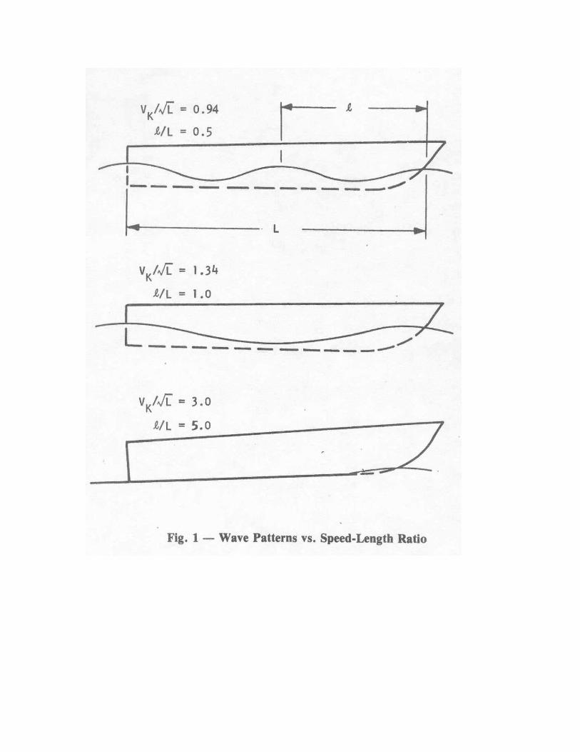
My talk today will discuss the hydrodynamic evolution of the three basic monohull forms; describe their upper limits of non-dimensional speeds; define their relative transport efficiencies and useful load fractions, and finally define the geometric and operational characteristics of a unique displacement type hull having a maximum speed of 50 kts. that meets the suggested operational requirements for an intercontinental high speed sea lift ship. Most of the presentation is based upon first principles of naval architecture that must be familiar to this audience. Also, since high speed and high sea state usually have an adversarial relationship, the results of recent experimental studies at the Davidson Laboratory, Stevens Institute of Technology will be presented which demonstrate the beneficial effects of active controls in making these conditions compatible. Again this discussion will be based on first principles of dynamics. Relative to restricting this talk only to monohull forms, it is because this hull form is ubiquitous; the shipbuilding industry has extensive experience in building these hulls; monohulls are less expensive; have acceptable growth potential; and have an excellent record of operational reliability. Certainly, other hull forms such as catamarans, SWATH, air cushion craft, etc also have their own advantages –perhaps these can be addressed at a future time. Significance of Speed/Length Ratio (SLR) Based on calm water resistance considerations, the appropriate selection of a particular type of hull form is mainly dependent upon its operational speed/length ratio (SLR). As you all know, this is defined as the speed in knots (Vk) divided by the square root of the load water line length (LWL) in feet. Thus, SLR = Vk/√LWL The following paragraphs present a very brief description of the hydrodynamic phenomenon associated with increasing SLR and how they influence the geometric configuration of the hull form. Hull Generated Waves: A marine craft moving thorough the water surface generates a transverse wave system having a velocity (Ck) equal to the boat speed (Vk). This self- generated wave system represents an irrecoverable expenditure of propulsive energy that is a consequence of the “wave-making” resistance of the hull. As a first order approximation, the characteristics of this transverse wave can be likened to sine waves where the length of the wave, Lw (feet), is related to its celerity, Ck, (apparent velocity in kts) by the following equation: Ck = 1.3√ Lw Interestingly, the SLR of every wave is thus equal to 1.3 regardless of its length.. The SLR of a ship is however very much dependent upon hull length and speed in deep water. Since Ck = Vk, the following relation exists between the wavelength generated by the ship (Lw) and its load water line length (LWL) as a function of SLR

Lw/LWL = SLR2 / 1.80 Tabulating this result: SLR Lw/LWL
0.94 0.50 1.10 0.67 1.16 0.75 1.34 1.00 1.90 2.00
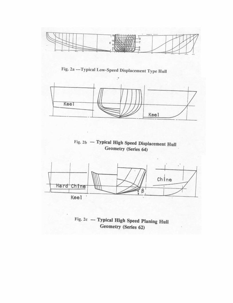
Thus, as the ship speed (or SLR) increases, the length of its generated transverse wave increases until at a SLR =1.34, the wavelength is equal to the hull LWL. At SLR > 1.34, the wavelength is larger than the ship length. This is illustrated in Figure 1. The significance of this ratio of Lw vs. LWL as related to each hull type will be discussed subsequently. Negative Pressures on Convex Surfaces: One other major hydrodynamic phenomenon associated with high speed itself is the generation of negative pressures along convex surfaces of the hull i.e. convex longitudinal buttock lines or convex curvatures in the transverse plane—particularly in the bilge area. The influence of this effect on hull form selection is also discussed subsequently. The existence of these negative pressures can be easily demonstrated by allowing a spoon to pivot at its upper end and slowly moving the convex face of its lower bowl into the vertical water stream flowing from an open faucet. It surprises some people to see how rapidly the spoon is drawn into the stream rather that be repelled by it. Hull Form Dependence on Speed-Length Ratio Having described the two major hydrodynamic effects of increasing water speed, the dependence of hull form as a function of increasing SLR can now be discussed. Displacement Hulls: Lines drawing for a typical displacement hull form are shown in Figure 2(a). The principal geometric characteristics are:
Fine water-line entrance angle. Longitudinally convex buttock lines-particularly in the stern
region. A narrow stern (in plan view) Convex curvature of bilges, usually of constant radius.
The displacement ship is entirely supported by buoyancy forces. The convex shape of the waterlines, buttock lines, and bilges are required to prevent flow separation -especially at the stern and so minimize the residual drag component of the hull. At the normal operating speeds of displacement hulls the negative pressures on these convex surfaces are relatively small and have a minor effect on hull performance. This is no longer the case if the speed of the displacement hull is substantially larger than its proper design speed.
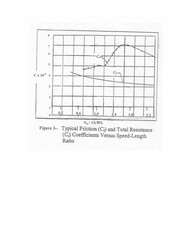
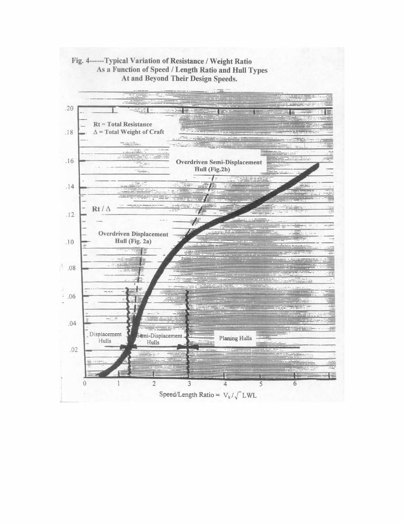
Referring to Figure 1 it is seen that, at Vk / LWL > 0.94, the hull spans two or more wave crests. There is a small sinkage of the hull and a slight increase in hull trim. At V k / LWL > 1.3, the wavelength is larger than the hull length and the hull begins to squat and trim down by the stern. The ship is literally climbing up the back of its own bow wave. At these speeds the flow along the convex geometry of the hull bottom develops large suction pressures that further increase the squat and trim of the vessel. The result is that, for Vk/ LWL > 1.3, the hull resistance begins to increase dramatically and thereby becomes a practical barrier to further increases in speed. Figure 3 is a plot of total resistance coefficient versus speed/length ratio. It clearly demonstrates this “wall of resistance” at a speed-length ratio equal to 1.34. Figure 4 is a typical plot of the resistance/weight ratio vs. SLR for a displacement hull. The very sharp increase in resistance at SLR > 1.25 is most obvious. When towing tank models of displacement type hull forms are driven at speeds substantially in excess of SLR = 1.3, the visual evidence of the excessive resistance is dramatic. The model squats and trims by stern to the extent that the stern deck is nearly underwater. In addition, the transverse flow around the bilges clings to the side of the model and becomes a nearly vertical spray sheet that completely obliterates a view of the model. Thus the upper limit of application of a displacement hull form is at a SLR which is approximately equal to 1.3. Most displacement type hulls actually operate at SLR > 1.0. In order to operate satisfactorily at higher SLR the displacement ship hull form must be replaced by a configuration that is compatible with the hydrodynamic phenomenon associated with higher speeds. This leads to the so-called "semi-displacement" hull form. Semi-Displacement Hulls: These hulls are designed to avoid the large squat and trim angles associated with displacement hulls operating at SLR > 1.3. At these speeds, the length of the bow-generated waves will always be larger than the hull length. Thus regardless of hull form, the vessel will always be advancing up the oncoming flank of its own bow wave. Hence the major objectives in configuring a suitable hull geometry are to avoid suction forces along the aft longitudinal buttock lines and to reduce the running trim angle. This is accomplished by using straight buttock lines aft that terminate at a sharp, partially submerged transom whose width is somewhat larger than the narrow width of a displacement hull. This configuration develops positive dynamic pressures (rather than the suction pressures associated with convex buttock lines) that tend to lift the stern, raise the hull slightly, and reduce the trim. These positive dynamic bottom pressures are not very large so that the vessel is not a planing hull but instead is identified as “semi-displacement” or “semi-planing”. A typical lines drawing for a semi-displacement hull is shown in Figure 2(b). It is characterized by:
Water entry lines that are fine, and straight buttock lines in the afterbody with a slight steady rise aft. These terminate at a sharp wide transom that is partially submerged.

Round bilges along the entire hull -although some designers may prefer a combination of sharp chine aft with round chine forward or vice-versa. Straight, Vee-formed cross-sections in the forebody.
The characteristic behavior of semi-displacement hull form with increasing speed-length ratio is as follows: 0< SLR < 0.9: With increasing speed the flow separates from the transom so that is completely ventilated to the atmosphere. The hull squats slightly and trims up slightly. 0.9< SLR < 2.0: The hull attains its maximum squat (substantially less that for a displacement hull) and maximum trim (approximately 2 degrees). There is some evidence that the transverse flow from the bottom is clinging to the round bilges due to the negative pressures in this area. In this speed range however there is only a small effect on hull resistance. 2.0 < SLR <3.0: The hull rises to essentially its original static draft and the trim angle decreases with increasing speed. The round bilges develop a spray formation that rises rapidly with increasing speed. This spray climbs up on the sides of the hull and can reach to the deck level at SLR approaching 3.0. For further increases in speed, the trim is further reduced, the spray is intensified and the total wetted area becomes significantly larger that the static wetted area. For SLR > 3, the resistance of the hull usually increases very rapidly. Although properly designed spray rails can attenuate the bow spray there is insufficient dynamic lift for the craft to plane. Figure 4 compares the typical values of resistance/weight ratio for semi-displacement hulls with those for displacement hull as a function of SLR. It is seen that the semi-displacement hull easily passes through the so-called resistance barrier for a displacement hull (SLR=1.3). However, at SLR equal to approximately 3.0, the resistance of the semi-displacement hull increases very rapidly and thus defines a practical upper limit for the operational speed of such hulls. In summary, the semi-displacement hull form is recommended for operation in the region of SLR between approximately 1.3 and 3.0. For higher speed the hard chine planing hull form is required. Hard-Chine Planing Hulls: The hard-chine planning hull is configured to develop positive dynamic bottom pressures at high speed. These positive pressures actually lift the hull and thereby reduce the buoyant component of hull support. As a consequence the wetted bottom area, when planning, is substantially smaller than the static wetted area. Unfortunately, the addition of induced drag associated with the development of dynamic lift results in a total resistance- weight ratio that is substantially greater than those for a displacement or semi-displacement vessel at their design speeds. A typical lines drawing for a planing hull is shown on Figure 2(c). The following geometric features are evident:
Complete avoidance of convex surfaces (except for the bow area which is out of the water at planing speeds) to avoid the development of bottom suction pressures. Sharp edge chines at the intersection of the bottom and sides to insure
complete separation of the transverse flow component from the bottom. A deeply submerged wide transom with a sharp trailing edge to insure
complete separation of the longitudinal flow from the bottom- thus insuring that the entire transom is ventilated to the atmosphere. Straight horizontal buttock lines at the aft end. Vee-bottom transverse sections with the deadrise increasing towards
the bow. The deadrise is required to reduce the wave impact loads in a seaway and to provide lateral wetted surface required for course-keeping stability and maneuvering.
Although intended for high SLR operation, the planing hull must pass through the entire range of SLR prior to attaining its design speed.. The planing hull has somewhat larger resistance that the displacement or semi-displacement hulls up to a SLR of approximately 3 (pre-planing speed). This is attributed primarily to the sharp chines and submerged wide and sharp transom that promote flow separation and hence increase the form drag component of the hull. The planing hull easily passes through the speed “barriers” for a displacement ship (SLR = 1.3), and the limit for a semi-displacement hull (SLR = 3.0) In contrast to the other hulls, the performance of a planing hull is very dependent upon the longitudinal location of the center-of-gravity that controls the trim angle of the craft when planning. The trim angle in turn has a major effect upon the resistance/weight ratio. Typically, the resistance of a planing hull is a minimum at trim angles between 3-4 degrees and increases for both higher and lower values of trim. If the center of gravity for a given hull cannot be varied, then transom flaps or transom interceptors can be used to change the trim. Analytical methods are available for evaluating the effect of center-of-gravity position or transom flap design on the equilibrium running trim angle. In conclusion, hard-chine planing hulls are the recommended hull form when operating at SLR > 3.0. Summary: In summary, referring to Figure 4, it is seen that displacement hulls operating at their design speed have the lowest value of resistance/weight ratio. In fact commercial vessels operate at SLR of approximately 0.9 that is well below the limiting value of 1.3. Semi-displacement vessels and high- speed catamaran hulls operating at their design SLR have a resistance/weight ratio that is nearly 10 times larger than for the displacement ship. Planing craft have a resistance/weight ratio that is approximately 20 times larger than the displacement type hull. Thus if small craft are intended to run at high speed, they will require the largest thrust per pound of displacement. The recommended operational regimes for each of the hull types are also indicated on Figure 4.

Comparison of Power Requirements for Various Hull Types It is of interest to compare the expected horsepower for displacement craft, semi-displacement hulls and planing craft at their maximum values of speed/length ratio as defined on Figure 4. For this illustration, estimates are made for a 70ft LWL hull having a displacement ∆ = 30LT. This combination of length and displacement results in a slenderness ratio (LWL/∇1/3) = 6.9 which is a most favorable. value The symbol ∇ represents the displaced volume. To estimate the relative power requirements of each craft type the following assumptions are made: Bare Hull Resistance: Obviously, the resistance of any hull is dependent upon its precise hull shape, loading, and speed. There are published analytical methods and hull series data obtained from systematic model tests that can be used to accurately estimate resistance for a given configuration. It is not the intention of this talk to examine specific hulls but rather to discuss the relative magnitude of the powering requirements as related to the three basic monohull forms previously defined.. For this simplistic objective, the curve of hydrodynamic resistance/weight ratio vs. speed/length ratio plotted in Figure 4 has been used to estimate the bare hull resistances. Appendage and Aerodynamic Resistance: For the purposes of this illustration their combined resistances will be taken to be 10% for a low-speed displacement hull and 20% of the bare hull resistance for a high speed planing craft. These are typical values but, if desired, these resistance components can be calculated for a specific hull using published analytical methods. Overall Propulsive Coefficients (OPC): These include components such as thrust deduction, wake fraction, open-water propeller efficiency, and propeller relative rotative efficiency. Obviously, each is dependent upon hull form, type of propulsor, and speed. Again for the purposes of this simple illustration, the OPC will assumed to be 0.60 for all hulls and speeds. Estimate of Shaft Horsepower (SHP) For Each Monohull Form Since each monohull form can operate over a range of acceptable speed/length ratios, a value was selected towards the high end of acceptable values of SLR. Recalling that each hull has a water-line length of 70 ft and a displacement of 30LT and using the values of added resistance components and OPC provided above, the following estimates are provided for the SHP of each monohull form when operating at its maximum acceptable value of speed/length ratio (see Figure 4) . Hull Type Vk/√LWL Vk Rh /∆ Rh Rapp+air Rt OPC SHP Displacement 1.2 10.1 .018 1,210lb 120lb 1,330lb 0.60 70 Semi-Displacement 2.8 23.0 .095 6,400 770 7,170 0.60 840 Planing 6.0 50.0 .147 9,990 2,000 11,990 0.60 3,070 Where: SHP = Rt x Vk x 1.69 OPC x 550
The obvious conclusion is that, for a given length and displacement of a boat, and using the hull geometry consistent with its operational speed/length ratio, the required shaft horsepower increases very rapidly with speed. In fact, the 70 ft. planing hull, driven at 50 knots,will require nearly 44 times the horsepower that the displacement hull requires at 10 knots even though the speed was increased by a factor of 5. The direct result is that, in addition to the high initial and operating costs of high-speed planing boats, the machinery, fuel weight and space requirements for these boat are increased substantially resulting in a significant reduction in payload. These are the costs of high-speed planing boats which begs the question—is faster better and can it be justified? I will now discuss the reduction in useful load associated with high-speed, relatively small, boats. Useful Load Fractions For Various Hull Types Useful load fraction is defined as the sum of the weights of the payload, fuel, crew, and potable water. It represents the difference between the total displacement of the craft and the light-ship weight. The light ship weight is the sum of the following major components: Ws = weight of hull and super-structure. Wp = weight of propulsion system. Wo+a = weight of outfit and auxiliary systems For the purposes of this illustration estimates are made of the useful load for each of the monohull types previously described. It will be recalled that each craft type had an LWL = 70 ft and a total displacement ∆ = 30LT (67,200 lbs). It is further assumed that all craft are constructed of aluminum and are powered by diesel engines. Obviously, somewhat different results will be obtained if other materials or power plants are used. However I believe that the general conclusions related to the relative values of useful load fractions will remain unchanged. Weight of Hull and Super-Structure (Ws): The hydrodynamic loads resulting from operation in waves govern the design and hence the weight of the structure. These loads become more severe with increasing speed and sea-state. The structural weight of any boat is best estimated by a detailed design of its hull structure—but this is beyond the intent of my talk. However based upon trends for typical mono-hulls the structural weight fractions (Ws/∆) for various types of 30-ton mono-hulls are taken to be as follows: Displacement Craft-------------- Ws/∆ ≅ 0.23 Semi-Displacement Craft------- Ws/∆ ≅ 0.26 Planing Craft---------------------- Ws/∆ ≅ 0.30 It is again emphasized that these structural weight fractions are estimates to be used only for the present illustration and should not be freely applied.

Weight of Propulsion System(Wp): This includes the engines, reduction gear, propellers, shafts, support struts, etc. Based upon a review of typical propulsion system installations, it is estimated that the weight of the total propulsion system is approximately 25% greater than the weight of the engine alone. Also, a review of published engine weight data indicates that the average weight of diesel engines is approximately 6.5 lbs/hp. Thus; Wp/∆ = 6.5x1.25 x SHP = 8.13 SHP/∆ Where SHP for the three 70 ft. mono-hull types, each having a displacement of 30 LT, are given in the previous tabulation. Thus; Hull Type Vk (max) SHP Wp/ ∆ Displacement 10 kts 70 0.01 Semi-Displacement 23 840 0.10 Planing 50 3,070 0.36 Weight of Outfit and Auxiliary Systems (Wo+a): The outfit weight fraction is assumed to be the same for the three mono-hull types. A typical value of the outfit and auxiliary weight fraction is taken to be: Wo+a /∆ ≅ 0.12 Comparative Useful Load Fractions: Using the various weight fraction estimates given above, a typical useful load fraction for each mono-hull type is now summarized: Hull Type Vk/√LWL Ws/∆ Wp/∆ W(o+a)/∆ Wls/∆ Wul/∆ Displacement 1.2 0.23 0.01 0.12 0.36 0.64 Semi-Displacement 2.8 0.25 0.10 0.12 0.52 0.53 Planing 6.0 0.30 0.36 0.12 0.78 0.22 Where: Wls = light-ship weight Wul = useful load Summary It is seen that the 50 kt planing version of the 70 ft-30 LT mono-hull has only 34% of the useful load of a comparative 10 kt displacement form. Also, the useful load of the 23 kt semi-displacement hull version of the 70 ft-30 LT monohull has 83 % of the useful load of the displacement hull but nearly twice that of the planing hull. These differences are mainly attributed to the large resistance of the 50 kt planing hull. The weight of the propulsion system of boats designed for high speed-length ratio (these are usually relatively small planing craft) becomes a most significant component of the empty weight. In conclusion high speed/length ratio craft are very costly in both their reduced useful load capacity and, of course, in their increased acquisition and operating costs. These features are compromised for the sake of high speed. An operator or boat
owner must surely develop convincing arguments to justify high speed-length ratio planing boats! In fact most existing “high-speed’ commercial and military vessels are not of the planing type but rather are of lower speed length ratio, such as the semi-planing type, where their high useful load fractions make these vessels profitable to operate. A Concept for a 50-Knot Displacement Hull The combination of 50 knots with a hull operating in the displacement mode may seem, at first glance, to be a contradiction of capabilities. This conclusion follows from the conventional wisdom that a displacement type hull is a relatively low speed ship while 50 knots is usually associated with planing hulls. If we revert to the earlier discussions in this talk you will recall that the speed/length ratio was shown to be the dominant factor in selecting a suitable hull shape for a given application and each monhull type was identified to have a maximum value of speed/length ratio above which it will experience sudden large increases in resistance/displacement ratio. Further, it was shown that the horsepower per ton within the range of speed / length ratios suitable for a hull in the displacement mode was impressively smaller than those for the speed / length ratios suitable for semi-planing or planing hulls. I thus became curious as to whether a 50 kt displacement ship was viable and if there was a possible application for such a ship. The following discussions describe the possible application and requirements of this unique ship; its powering requirements; its performance in calm water and waves; and finally its weight fractions including structure, propulsion system, payload, fuel load, and range. A complete analysis of this ship was given in Reference 1. Operational Requirements The motivation for even considering this ship was the rather ambitious requirements for a high- speed sealift ship as identified by the US military. The broad operational requirements were stated to be: Maximum speed----------------------------50knots Payload------------------------------------12, 000 LT Range-------------------------------------- 9,000 nm SHP/ Displacement-------------------≈ 1/2 that of exiting 50 knot craft. While 50 kt. hulls do exist, they are of modest size, require very large horsepower per ton of displacement, and cannot transport large payloads over intercontinental routes. These include hull forms such as SES, ACV, Catamarans, Planing monohulls ,Semi-displacement, etc. They all operate at speed/length rations greater than 1.3. Let us first identify and then examine the Transport Factors ( efficiency) of some existing and projected high speed hull designs.
Transport Factors (Efficiency) of High –Speed Marine Vehicles: Various definitions of Transport Factor (TF) have been used in past studies. The definition used in this talk is chosen to be consistent with recently published data presented by the US Navy’s David Taylor Model Basin (Ref 2). The Transport Factor is there defined as: TF = Displacement x Speed = ∆ x V / SHP x 550 Installed Horsepower x 550 or: TF = ∆ x V x OPC Rt x V Where: Rt = total resistance, lbs V = ship speed, ft/sec SHP = shaft horsepower = Rt x V/OPC
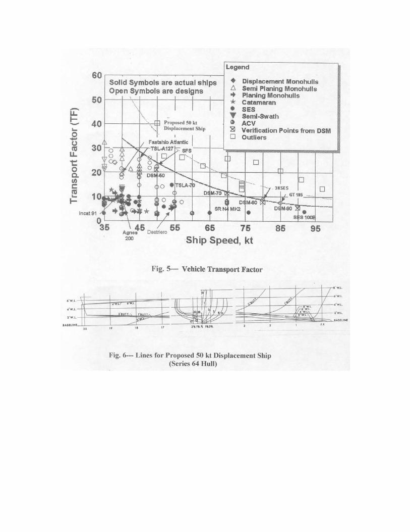
∆ = total ship displacement, lbs OPC = overall propulsive coefficient Thus, TF = (∆ / Rt) x OPC The term ∆/Rt is the “lift-drag’ ratio of the ship and is associated directly with the hydrodynamic efficiency of the hull. Figure 5, taken from Ref.2, provides TF data for a wide range of high- speed vehicle types for speeds between 35 and 90 kts. It is seen that the envelope of maximum values of TF decreases rapidly with increasing speed. At 50 kts the maximum value of TF is approximately 20. Thus the objective of the present study was to define a hull that has a TF equal to approximately 40! Selection of Hull form: In 1961, MARAD sponsored model tests at the Davidson Laboratory to define the calm water resistance and sea keeping characteristics of high-speed displacement hulls. (Ref. 3). In 1965, the David Taylor Model Basin also conducted resistance tests on a series of high-speed displacement hulls forms referred to as Series 64. (Ref. 4). These tests were conducted over a speed/length ratio range from 1.0 to 5.0. Both hull series had high length/beam ratios and hull forms that were very fine and narrow; had low block coefficients; low displacement/length ratios; and very fine water line entrance angles. These geometric characteristics are especially compatible with the desire to drive displacement hulls at high speed. Hence a comprehensive set of model test data was available upon which to undertake this study of a 50 kt displacement hull.
It will be recalled from the earlier discussions, that the maximum speed/length ratio, SLR, of a displacement hull should not exceed the value of 1.3. If this SLR is combined with the 50 kt speed requirement, the water-line length of the ship will be 1480 ft.! Although this is an impressive size, it would not be the longest ship ever built. In 1979, the Sumitoma Shipyard in Japan, actually launched a 1500 ft long tanker (named the Happy Giant) for a Norwegian company, but its speed was only 13 kts. This ship was classed by Lloyds. Just last year Bureau Veritas described the design of an Ultra Large Container Vessel having a length of over 1300 ft. and a speed of 25 knots. Maybe 1480 ft. is not out of the question. Non-Dimensional Hull Characteristics: A block coefficient of 0.43 was assumed since fine waterlines would be consistent with high speeds. Further, a displacement /length ratio of 20 was selected since the residual resistance/displacement ratio is smallest at this loading. Model No. 4804 of Series 64 was selected for this study since it most closely matched the desired hull particulars. Figure 6 shows the lines for this hull. The stern is wide and flat below the design waterline, the buttocks are straight lines at the afterbody, and the transom is immersed with sharp cutoff at the end. Because of the contemplated 50 kt speed, it is expected that the afterbody will have a hard chine or knuckle. This will avoid the development of negative pressures in the bilge area. The following is a tabulation of its principal non-dimensional characteristics: Cb 0.43 LWL/B 12.7 B/H 4.0 ∆/(0.01 LWL)3 20 S/(∇ x LWL)1/2 16.6 1/2ε 5.2 deg where: 1/2 ε = Waterline entrance half angle H = Draft at full load S = Wetted surface area of hull at full load B = Waterline beam at full load LWL = Waterline length at full load Cb = Block coefficient at full load ∆ = Full load displacement, LT Final Dimensions of Notional 50 kt Hull Design: Using the above parameters, the following principal dimensions of the notional 50 kt displacement hull were established: LWL = 1480 ft. B = 117 ft H = 30 ft ∆ = 63,800 LT S = 161,300 ft2 1/2ε = 5.2 deg Cb = 0.43
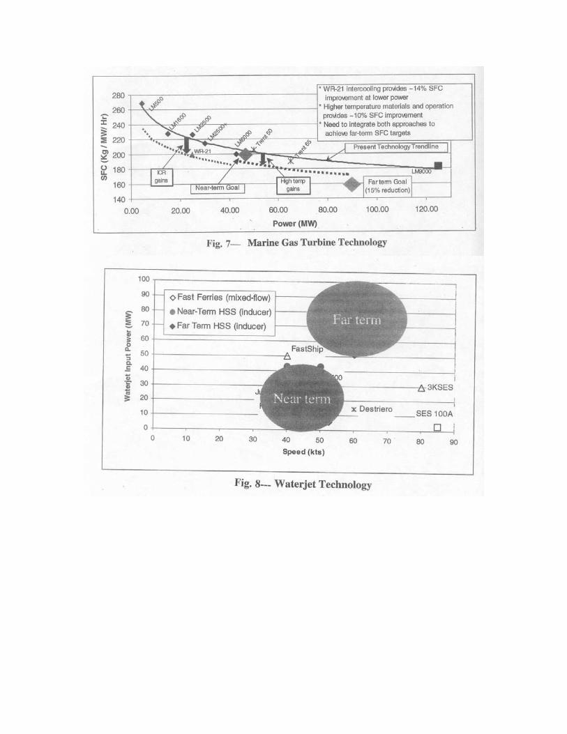
Estimated Hydrodynamic Resistance and Powering: Using the above values of non-dimensional coefficients with the data presented in Ref.4, the estimate for the residual resistance/displacement ratio of this hull is : Rr / ∆ = 15 lb/ LT, so that Rr = 15 x 63,800 = 957,000 lb Using the wetted surface area listed above and the appropriate Reynolds number and associated friction coefficient, the frictional resistance is estimated to be: Rf = 1,353,000 lb Therefore, the total resistance at 50 kts is Rt = 957,000 + 1,353,000 = 2,310,000 lb Estimated Shaft Horsepower (SHP) at 50 knots: EHP = Rt x Vk x 1.69 / 550 = 354,900 hp OPC = 0.60 (estimated) SHP = EHP/OPC = 591,000 hp Allowing for a 10% margin , the total installed shaft horsepower is 650,000 hp. Transport Factor For 1480 ft LWL Displacement Ship at 50 kts. Using the above calculated Rt and a displacement of 63,800 LT, the transport factor TF is calculated to be: TF = ∆ x OPC = 63,800 x 2240 x 0.60 = 34 Rt 2,310,000 x 1.10 This value is plotted on Figure 5 and clearly demonstrates the significantly greater efficiency of a very long displacement ship compared to other hull forms when operating at 50 kt.. Thus one of the operational requirements postulated for a high- speed sealift ship is attained. Possible Propulsion Systems: Prime Movers: It is believed that gas turbines will be the preferred engines for high- speed, sea- lift ships. This is due primarily to their lightweight, compactness, fuel efficiency, and their potential to develop large power. Fortunately, the gas turbine industry continues to pursue the development of lighter, more powerful, and more fuel efficient engines. These anticipated future results will be essential for the successful design of a 50 kt displacement ship. Figure 7, taken from Ref. 5, shows the specific fuel consumption rate and power of existing and developmental gas turbines in terms of near and far time goals. Of particular interest is the LM9000 gas turbine which is being developed by General Electric with support from the US Department of Energy. This turbine has a projected
maximum power of 125 MW (167,000 bhp) and a fuel consumption nearly 15% less that the existing LM6000 , 40MW (54,000 bhp) turbine. Rolls Royce is developing the 47.5 MW (65,000 bhp) turbine for possible use on the FastShip Atlantic project. Four LM 9000 turbines would easily power the proposed displacement hull at 50 kts. Propulsors: Both waterjets and propellers should be considered as possible producers of the very large thrust required for the present 50 kt ship. ( total resistance equal to 2,310,000lbs). Waterjets: Waterjet propulsion appears to be the present day preferred propulsion system for high-speed vessels. Unfortunately, large 50 kt ocean going displacement ships require very large amounts of power to be transmitted to the waterjets for propulsion. The largest near term waterjet that is currently being designed is the KaMeWa 325 (inlet diameter = 10.7 ft) which is expected to absorb 49 MW ( 66,000 bhp). Thus for the present application, nine such waterjets, each combined with a Rolls Royce 325 turbine, will provide the required thrust. The installation of nine waterjets will be difficult but can be accomplished. Certainly, in the far term, it is expected that larger capacity waterjets will be developed . Figure 8, taken from Ref.5, demonstrates the power rating and design speed of existing and developmental waterjets. It is to be noted that the far term powering objectives, 100MW (134,000 bhp) very much exceed the power absorption of existing waterjets. If these objectives are indeed achieved, they will facilitate the design of this 50 kt ship. Some of the disadvantages of waterjet propulsion include the cutting of many large holes through the transom to accommodate the exit nozzles; the loss of displacement in the aft region of the hull due to containment of large masses of water in the watejet ducts; and aeration of the waterjet inlet can result in a sudden reduction in shaft torque which can damage the propulsion machinery. Nevertheless, waterjet propulsion should be considered to be an option in the present design. The other option for providing thrust is to use propellers and this is now discussed. Propellers: Propellers are reliable thrust producers and have a long history of success. However, a common first reaction to considering propellers for 50 kt ships is that cavitation will be a problem; the added resistance of propeller shafts and their support struts can be significant; and the effective draft of the ship due to the propeller will be increased. Consequently, since the waterjet minimizes these effects, it has been widely accepted for ship speeds of 50 kts or greater. For the present 50 kt displacement ship, its particular dimensions and geometric form substantially overcome the so-called limitations of a propeller installation. Further, an existing well documented propeller series can be used immediately to design a trancavitating propeller that produces much greater thrust that the largest waterjet that is being considered for future designs. In fact four such propellers

will provide the total thrust required to propeller this 50 kt ship. Compare this with the nine waterjets (yet to be developed) required to propel this ship. Let us consider the so-called limitations of a propeller installation and how the present large ship substantially overcomes them; Cavitation: Recall that the cavitation number ,σ, is defined as: σ = Po + Ph - Pv (1/2) ρ V2 large values of the cavitation number indicate less tendency for the propeller to cavitate and vice-versa. Where: Po = atmospheric pressure, lbs/ft2 = 14.7 x 144 = 2120 lbs/ft2 Ph = static water pressure, lbs/ft2 = ρgh Pv =vapor pressure of water, lbs/ft2 h = depth of propeller centerline below water surface at rest , ft. ρ = mass density of water, lbs-sec2 / ft4 V = ship speed, ft/sec In the present ship, the draft of the transom is approximately 10 ft. and the draft at mid-ship is 30 ft. Thus, if a 20 ft. diameter propeller is used, it will not extend below the ship base line. Also, the propeller shafts will be horizontal and penetrate the hull 10 ft. above the base line. Recall that this is a concept design and hence the dimensions are approximate. The quantity, h, is thus 20 ft and Ph =20 x 64.4 = 1290 lbs / ft2. Hence, neglecting the small value of the water vapor pressure, the cavitation number at depth is: σ = 2120 + 1290 = 0.48 (1/2ρ) (50x1.69)2
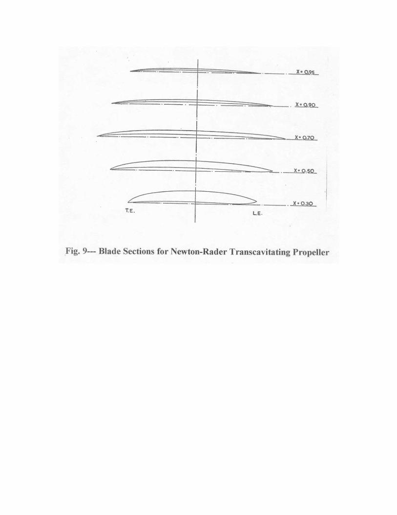
Notice that the large static water pressure at the deeply submerged propeller centerline results in an increase in cavitation number by 3410/2120 = 60 %. This in turn increases the vessel speed by 27 %-- for the same cavitation number = 0.48. Propeller Series: Conventional subcavitating propellers, such as the Gawn-Burrill (G/B) series (Ref.6) have been installed on planing craft operating at speeds up to approximately 38 kts . At higher speeds these propellers experience severe cavitation erosion problems and thrust breakdown. Fortunately, there is a developed series that can accommodate cavitation without the serious performance deterioration associated with the G/B series. This is the Newton-Rader (N/R) series (Ref.7) where the propeller develops a cavity over more than 85% of the blade surface which terminates beyond the trailing edge. (Fig.9) They are frequently referred to as transcavitating propellers. At typical values of advance coefficient, (J = 0.8), and a cavitation number of 0.50, the N/R propellers demonstrate a gain in efficiency of
approximately 20% compared with the G/B series. Full- scale experience with the N/R propeller on planing boats has shown minimal blade erosion at speeds up to 55 kts. Recommended Propeller for 50kt Displacement Ship: Using the Newton-Rader series, the following propeller was selected to meet the thrust requirements of the present design. Number of Blades----------------------------3 Diameter---------------------------------------20 ft Pitch/Diameter-------------------------------1.05 Blade Area Ratio-----------------------------1.15 RPM--------------------------------------------275 (1-w)= 0.94 (1-t)=0.90 ηrr = 0.97 ηo-----------------------------------------------0.63 Thrust/propeller = Rtx1.10= 642,000 lbs SHP x 1.10 = 171,000 hp Use 4 propellers: Total Ship Thrust = 2,568,000 lbs SHP x 1.10 = 686,000 hp The design of these propellers is based upon a well documented propeller series and they are certainly capable of being delivered in the present time frame with a minimum of research and development. This is in sharp contrast with the large development efforts involved in delivering suitable waterjets for this application. Estimated Seakeeping Charcteristics----Head Seas In addition to the desirable low resistance per ton of displacement for this 50 kt hull, its long length also has inherently excellent seakeeping characteristics. This conclusion follows from the fundamental observation that, for wave lengths shorter than 0.75 LWL, there is very little ship response at any speed. As stated in Ref..8, for these waves, “the exciting forces and moments are too small to cause appreciable motion so that the likelihood of deck wetness, high accelerations, and slamming is also small”. Consider the present 1480 ft LWL ship running in head seas having a significant wave height H1/3 = 30 ft.—this can be considered to be a relatively severe operating environment. Using the Pierson-Moskowitz sea spectrum relations, the following major properties of this 30 ft seaway are defined: Tmodal-(period of maximum wave energy)---------------15.1 sec. Lmodal- (wave length of maximum energy)---------------1170 ft Lmodal/LWL----------------------------------------------------0.79 Ranges of wave lengths which contain measurable energy: 155 ft ≤ Lw ≤ 1550 ft 0.10 ≤ Lw ≤ 1.05 LWL
It is seen that the wave length of maximum wave energy is only 0.79 LWL. Thus there will be relatively little response to this wave at any speed. Considering the dynamics of ship response, it is estimated that the natural pitch and heave periods of the ship are approximately 7.3 sec. Also, at 50 kts, the period of encounter with the 1170 ft. modal wave is 7.2 sec. Thus, although the ship is in a resonant condition, the wave forcing function is small so that only small ship motions are expected. The largest wave in the spectrum that has measurable energy has a length of 1550 ft and is 1.05 x LWL. Although this wave length would be expected to induce ship motions, its energy content in this sea state is very small so that only minimal ship motions are expected to occur. These qualitative conclusions were confirmed by seakeeping tests of the MARAD hull series conducted at the Davidson Laboratory in 1961.( Ref.3) A model of essentially similar proportions and loading was tested in a sea state having a significant wave height, H1/3 = 35.4 ft.. The following is a summary of some of the more important test results obtained at a simulated full-scale speed of 50 kts. Deck Wetness: With normal freeboard, there was no water shipped over the decks. Bow Immersion: It was found that the wave rise at the bow (relative to the static waterline) was only 20% to 25% of the bow freeboard. This is consistent with the lack of deck wetness. 1/10 Highest Bow Acceleration This was approximately 0.20g. Although not measured, the center of gravity accelerations will be < 0.20g. Slamming Impacts: One moderate slam in 37 cycles. Tranverse Stability in Beam Seas The metacentric height (GM) of the ship was estimated to be approximately 14 ft. This is approximately 12% of the ship beam (117 ft.) and is substantially larger than that for most commercial vessels. Thus adequate roll stability is implied. Considering an 80 kt. beam wind, and a reasonable ship profile area, the maximum roll angle is estimated to be 2.0 deg. Considering a beam sea with a significant wave height of 30 ft. and estimating the natural roll period to be 13.8 sec. and a roll damping factor = 0.20 critical, the significant roll angle is estimated to be 23 deg. This is considered to be acceptable. Seakeeping—Summary It has been shown that, primarily because of it’s long length, this 1480 ft. LWL ship will have excellent seakeeping characteristics in a seaway whose significant wave height is as much as 35 ft!
Estimated Weight Breakdown and Performance The structural weight estimate is based upon the application of a specially modified version of the American Bureau of Shipping’s SafeHull program. SafeHull is normally applied to conventional size hull forms but was modified by ABS to apply to the present long ship. They estimated that the structural weight would be approximately 24,000 LT. The propulsion system is expected to be one LM9000 gas turbine to drive each of the four 20 ft. diameter Newton- Rader propellers.. It will be recalled that this future gas turbine is expected to develop 167,000 hp so that it is a good match for the 171,00 hp required for each 20 ft. diameter propeller. The total weight of the propulsion system (including reduction gears, propellers, shaft, etc) were estimated using several unpublished sources and with contributions from Band, Lavis & Associates , Naval Architects. It was estimated that the weight of the propulsion system is 5,300 LT. The weight of the auxiliaries, including electric plant, electronics outfitting etc were estimated by Band Lavis & Associates to be approximately 5,000 LT. The light ship weight is thus equal to 24,000 +5,300 + 5,000 =34,300LT and the useful load is equal to 63,800 – 34,300 = 29,500 LT.or, 46% of the full load displacement. Performance According to Figure 8, the fuel consumption for the future LM9000 turbine is projected to be 0.30 lbs/hp/hr. Thus, for a range of 9,000 nm at a speed of 50 kts, where the horsepower ( including the 10% margin) is 686,000 hp, the required fuel weight is.16,500 LT. Hence, the payload will be 29,500 -16,500 = 13,000LT Summary of Estimated Performance of 50 kt Displacement Ship . Design Speed--------------50kts Displacement-----------63,800 LT Range----------------------9,000 nm Payload-------------------13,000 LT Transport Factor--------------35 In conclusion, this 1480 ft long displacement ship operating at 50 kts is expected to meet the operational requirements proposed for a high-speed logistic sea lift ship. This will be the longest ship ever built; will have substantially larger installed power that any other ship; and will have a maximum speed nearly twice as large as any existing seagoing transport.. This is the only ship concept that can meet the postulated requirements for large high- speed intercontinental maritime transport. If these ship dimensions appear to be overwhelming, serious consideration must be given to redefining the sea- lift requirements.

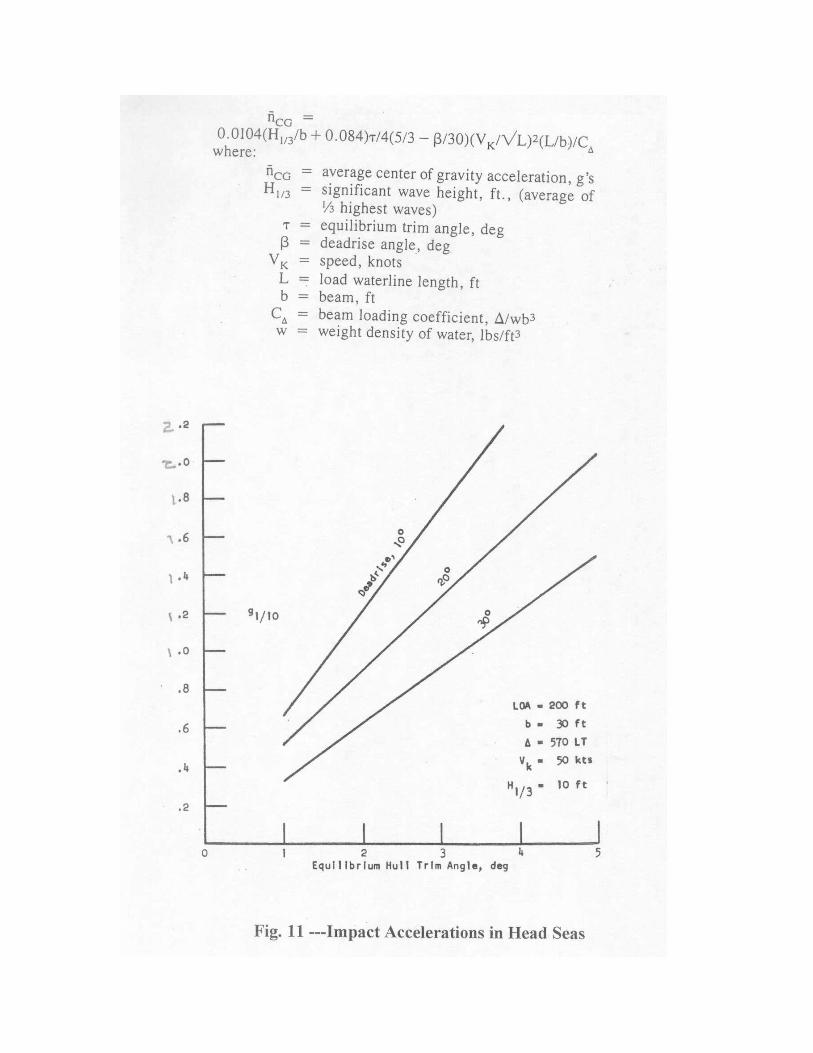
Potential of Active Flap Control in Improving Seakeeping Characteristics of High-Speed Planing Hulls. Perhaps the most important deficiency of high-speed planing hulls is their perceived inability to comfortably negotiate even a moderate sea state at high speed. I use the word “perceived” since, for many years, planing hulls were designed to achieve high speed in calm water without regard to their seakeeping ability. As a consequence the earlier hull forms were notoriously bad “seakeepers” and this impression has existed with the general public even to this date. There are many young boating enthusiasts who consider rough riding characteristics in a seaway to be an asset. They enjoy the “thrill” of being airborne when flying off the flank of one wave, then impacting against the flank of an oncoming wave, while being surrounded by large sheets of spray. The very popular jet-ski planing craft configurations (referred to as personal water craft) are notorious wave jumpers –to the great satisfaction of their owners. This does make for an exciting photograph (Fig.10) but, unfortunately, this is the image of high speed planing hulls that remains. Fortunately, for the vast majority of owners of high speed craft who prefer a civilized ride, research to improve the seakeeping of planing hulls has been most rewarding. Today, designers have the knowledge and tools to optimize the hull for both smooth and rough water performance. This research continues so that on- going improvements in the ability of high speed planing craft to operate in a seaway are expected. Current efforts in this regard involve the use of active transom flaps to attenuate the motions and accelerations of the craft in a seaway. I will now present some model test results of the effectiveness of active transom flaps that were recently obtained at the theDavidson Laboratory. It would be of interest however to first discuss existing ways to reduce the motions and accelerations of planing boats in a seaway. These include incorporation of the following design parameters. Existing Ways To Improve Seakeeping Behavior. Use of high deadrise hulls: Many of the early designs of planing craft had a very low bottom deadrise angle (less than 10 deg.) in order to achieve low resistance in calm water. This resulted in boats with very poor seakeeping qualities and were primarily responsible for the negative opinions associated with planing hulls. Today, it is well recognized that high deadrise angles (greater than 20 deg.) will improve seakeeping substantially. The use of deep-vee hulls (deadrise angles up to 30 deg.) is now quite common. Despite the fact that high deadrise angles increase the smooth water resistance, the improvement in seakeeking totally justifies their use. Fig.11 illustrates the powerful effect of high deadrise in reducing wave impact accelerations. Operation at small trim angles: The wave impact accelerations are now recognized to be linearly dependent upon the equilibrium running trim angle. The lower the trim angle the lower the impact accelerations. Fig. 11 clearly demonstrates the linear dependence of impact acceleration upon trim angle. A reduction in trim angle is readily achieved by forward transfer of ballast or by deflection of transom flaps or interceptors located on the transom.
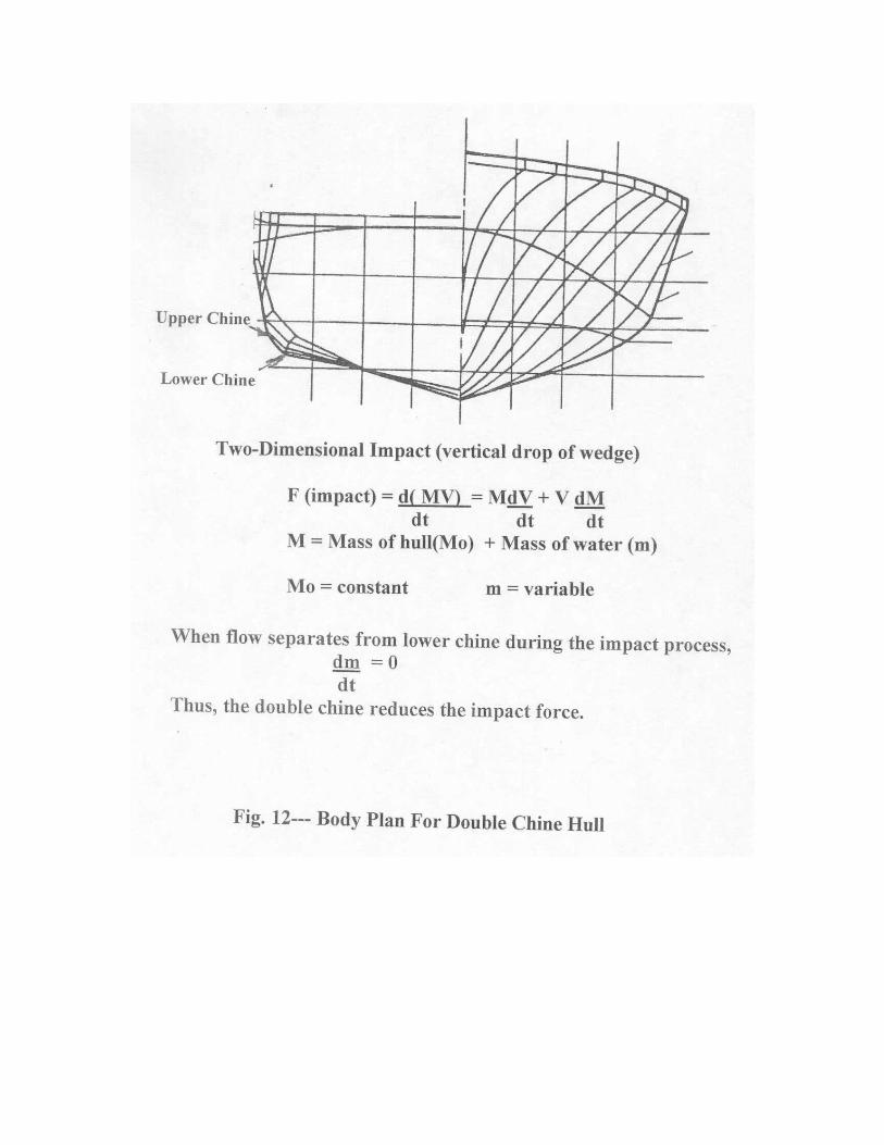
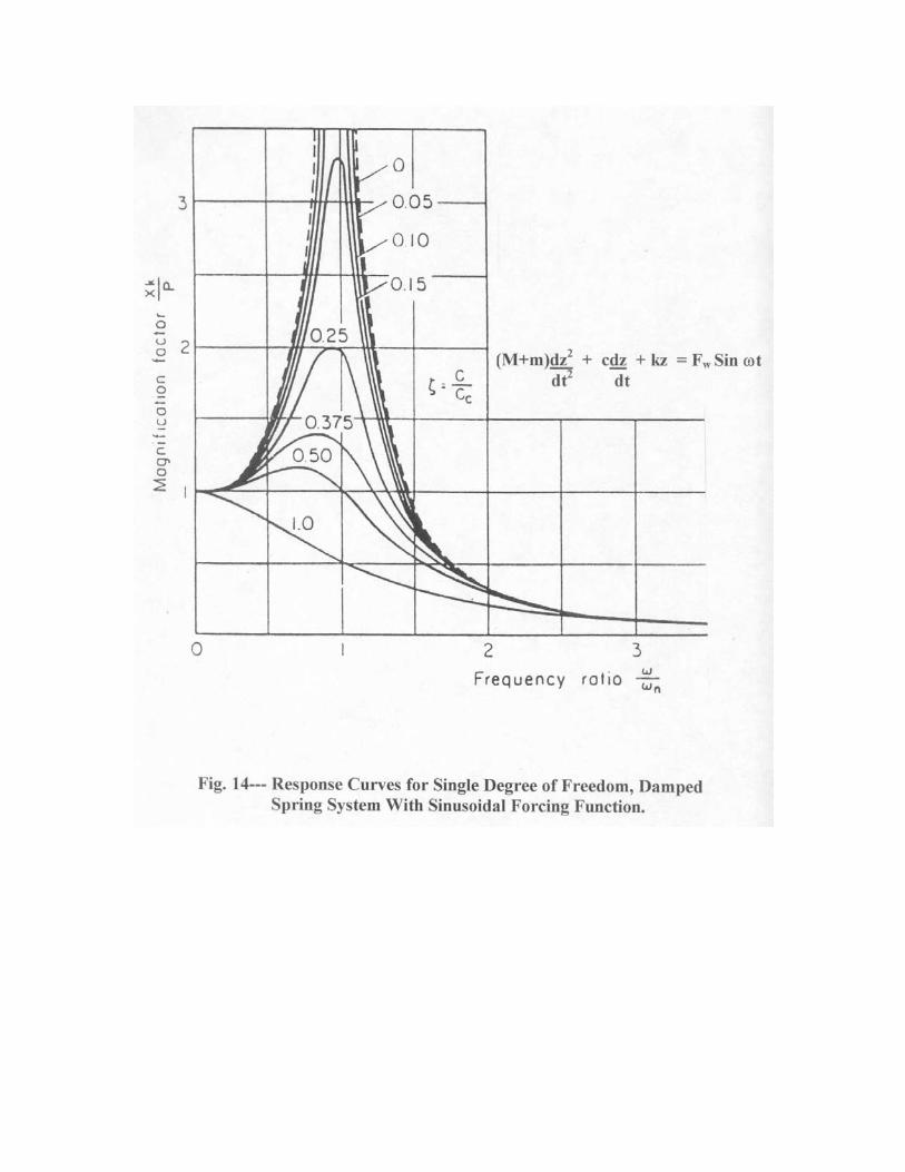
Reduction in beam of craft:: It has been well established both by analytical means and by full-scale and model tests that impact accelerations in waves vary inversely with increased beam loading coefficient C∆ = ∆/wb3 , where ∆ is the load on the water; w is the weight density of water, and b is the beam of the craft.. Thus, even a 10 % reduction in beam of the boat is expected to reduce the wave impact accelerations by nearly 30 %. The double chine hull form, Fig. 12, was developed by recognition of this relationship. The upper chine provides the beam necessary for roll stability at low speed and the lower chine, which causes flow separation during the impact process, provides the reduction in beam desirable for reduction in impact loads. The excellent seakeeping performance of the double chine hull has been demonstrated by the US Navy in full scale trials with a 95 ft. long 45 kt planing hull . Further, the Greek government is presently developing a hull series based upon the double chine concept. Use of Controllable Transom Flaps: Active control systems to attenuate the motions of high speed ferries in a seaway are in wide use today. However, their application to high speed planing hulls is just coming along even though, nearly 20 years ago, Wang Long-Wen of Delft University in The Netherlands published a theoretical and experimental report (Ref.9) demonstrating the beneficial effects of controllable flaps. These results, plus the long interest of the Davidson Laboratory in the seakeeping of planing hulls, motivated us to perform a simplified analysis and a brief series of model tests on a planing hull with transom mounted active control flaps. Descriptive Behavior of Planing Hulls in Head Seas: A planing hull running into waves can be considered to be a coupled 3 degree of freedom (heave, pitch and surge) dynamic system wherein the hull is acted upon by a forcing function generated by the waves it encounters. The dynamic properties of the hull are represented by the acceleration forces due to its physical and added mass and moments of inertia; the force and moment acting on the hull due to a unit displacement in heave or pitch (the so-called spring constants of the hull); and the force and moment acting on the hull due to its heave or pitch velocity (the so-called damping forces). The forcing function acting on the hull at a given speed is due to the interaction of the encountered wave properties (height, orbital velocities, accelerations, etc.) and the physical geometry of the hull. As expected, this is a complex non-linear mathematical system even without the force and moment inputs due to an active control system. For the purpose of illustration only, consider a linear one degree of freedom, (heave), damped, dynamic system subjected to a sinusoidal forcing function. This can be is represented by the following equation. (Fig.13) (M+m) dz2 + cdz + kz = Fw Sinϖt dt2 dt The first term is the force acting on the system due to acceleration of the physical mass, M, and the added mass, m; the second term is the force due to damping of the system taken to be linearly dependent upon the normal velocity of the hull and the damping coefficient, c; the third term is the force due to displacement where k is the effective
spring constant of the hull. The term on the right hand side is the wave force assumed to be acting on the system in a sinusoidal fashion at a frequency of ϖ. The hull also has natural pitch and heave periods of oscillation Neglecting the small effect of damping, the natural period of the hull, say in heave, is : ϖ =√ k/(M+m) An analogous expression can be derived for the natural pitch period of the hull but is not necessary for the purposes of this simplified presentation. These equations must be familiar to most of you since they were probably introduced to you during your first classes in physics. I am using them in this talk since they contain the essential basic ingredients that describe the motions of a damped, forced oscillatory system without the complications associated with the equations for a non-linear, coupled, controlled system. Also, the solution provides results that are easily understood and can be used to guide the design of the more complex active motion control system The solution of the above equation of motion is contained in all references dealing with the analysis of dynamic systems and so will not be repeated here. Fortunately, the results have been presented in the form of a classic plot that readily quantifies the response of a dynamic system to a sinusoidal forcing function. This classic plot is shown in Fig.14.---I’m certain you’ve all familiar with it. To summarize, this is a plot of amplification factor vs. ratio of applied frequency of forcing function /natural frequency of the dynamic system as a function of the damping ratio of the system. In terms of ship motion terminology, the magnification factor can be likened to the response amplitude operator (RAO), i.e. considering heave motion, the RAO is the ratio of the magnitude of heave of the craft to the height of the wave that caused this heave motion. Likewise this RAO can also represent the ratio of craft pitch amplitude to the slope of the wave that caused the craft to pitch. There is a separate curve for different values of damping ratio. It is noticed that the RAO decreases rapidly with increasing damping ratio particularly at resonance (ϖ =ϖn ). At super-critical damping ratios ξ < 0.70, the RAO is < 1.0 so that the heave and pitch motions will actually be less that the disturbing wave height or wave slope. Of course the maximum RAO occurs at all damping ratios when the frequency of wave encounter is equal to the natural frequency of the craft (so-called resonant condition). Because of the simplicity of these analytical results, I was curious to explore their possible applicability to planing craft operating free to trim and heave in regular head waves. Fortunately, there was a complete set of both analytical and model test results presented in Ref.9 for such a planing condition. The analytical equations of motion given in that reference represented heave and trim coupling with and without a transom flap control system. The magnitude of the flap deflection was made proportional to the angular velocity of the hull and hence effectively increased the pitch damping coefficient. Both sets of results were presented as ROA plots. The LOA of the test model was 1.5m; its average beam was 0.37m; the deadrise angle was 24 deg; and the model weighed 27.34kg. There was a full span flap that had a chord of 12% beam. Most tests
were run at a speed of 4.5 m/sec in regular waves having lengths between 1 and 6 times the hull length. The wave height was 0.055 times the beam. Fig. 15, taken from Fig. 28 of Ref.9, compares the calculated and experimental pitch motions of Ref. 9 for both the uncontrolled model and with the model having various amounts of flap deflection sensitivity to pitch velocity. The agreement between theory and experiment in both cases is excellent. To evaluate the potential applicability of applying single degree of freedom response curves (Fig.14) to estimate the pitch motions of this two-degree of freedom model, the pitch damping ratio for the uncontrolled model was estimated to be ξ =0.375. Superposing the ξ= 0.375 curve of Fig.14 on the curve and data of Fig. 15 shows quite good agreement between the simple single degree of freedom results and the two degree of freedom system. Of course this may be an entirely fortuitous result even though I have since applied this approach to other data obtained at the Davidson Laboratory and found similar good agreement. The limited success of this simplified approach of course depends upon things other than just the selection of a realistic value of ξ. It is not at all suggested that single degree of freedom solutions will always be applicable to each component of a coupled system. Much further study is required to understand and rationalize the nature of the present agreement. Fig. 16 presents the heave motion data for the coupled heave and trim model. As with the pitch, the agreement between analytical and experimental results are quite good. Superposed on this plot is the RAO for the single degree of freedom system taken from Fig. 14. In this case, the heave damping ratio, ξh was ,estimated to be 0..375. Again, the results of the simple single degree of freedom system seem to represent the two-degree of freedom results reasonably well. Of particular interest in examining Figures 15 and 16, is that both pitch and heave motions can be reduced significantly if the damping ratios are increased. Hence, the guidance for the design of an active control system to reduce the motions was that it increases the damping of the system. This resulted in an actively controlled transom flap whose deflections were dependent upon the pitch velocities. Thus; δf = k dφ dt where: δf = flap deflection, deg k = constant dφ = angular velocity, deg/sec dt The model was tested with an installed rate gyro that measured its pitch velocity. This signal was sent to a controller that then deflected the transom mounted flap in accordance with the above equation. Various values of k were used during the tests and the results are shown in Fig, 15 and 16 The value KCM = 0 represents the uncontrolled model. It is estimated that the value KCM = 2.0 represents a controlled model with critical pitch damping. As shown in Fig.15, the effectiveness of increased damping in reducing the pitch motions is indeed impressive. Superposed on these plots is the RAO taken from Fig.14 for a single degree of freedom system having value of critical damping ratio
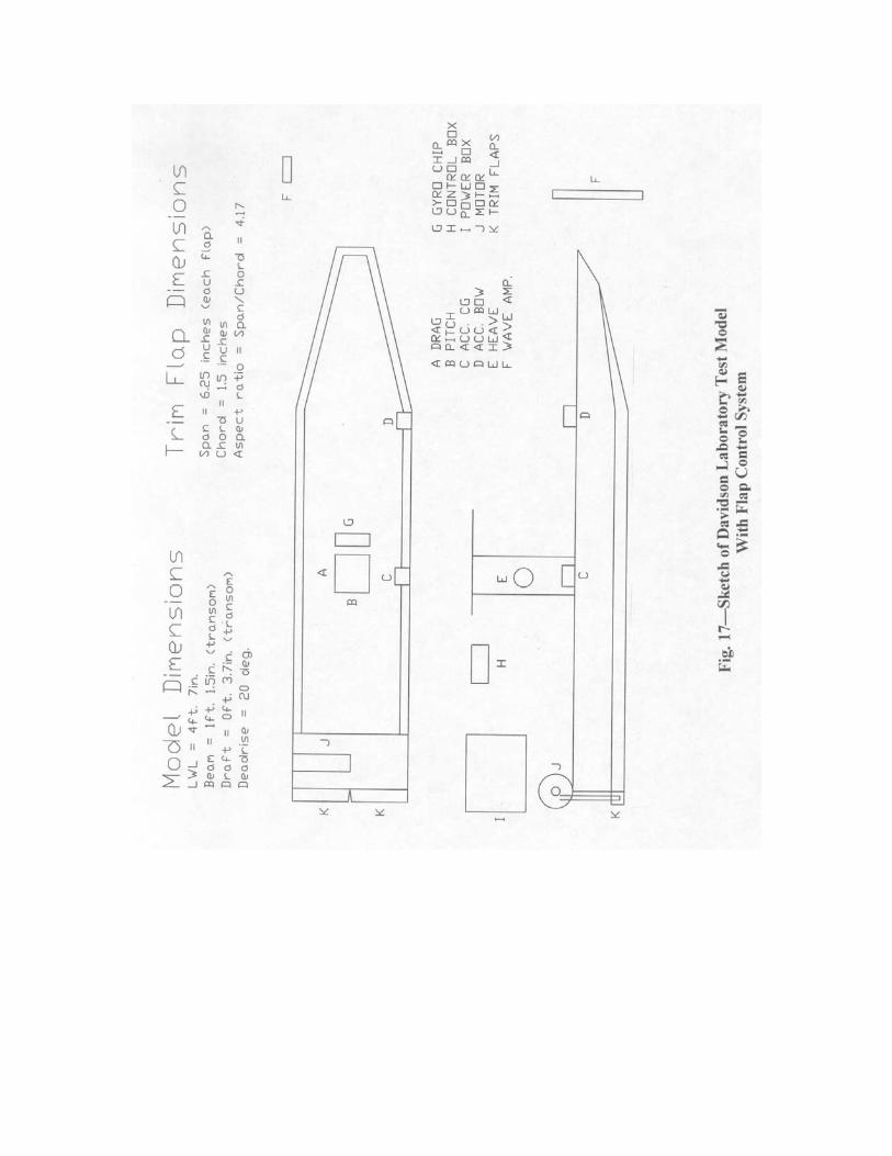
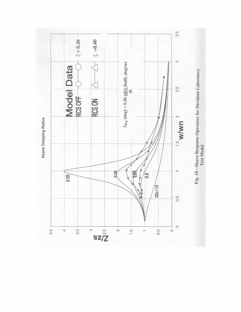
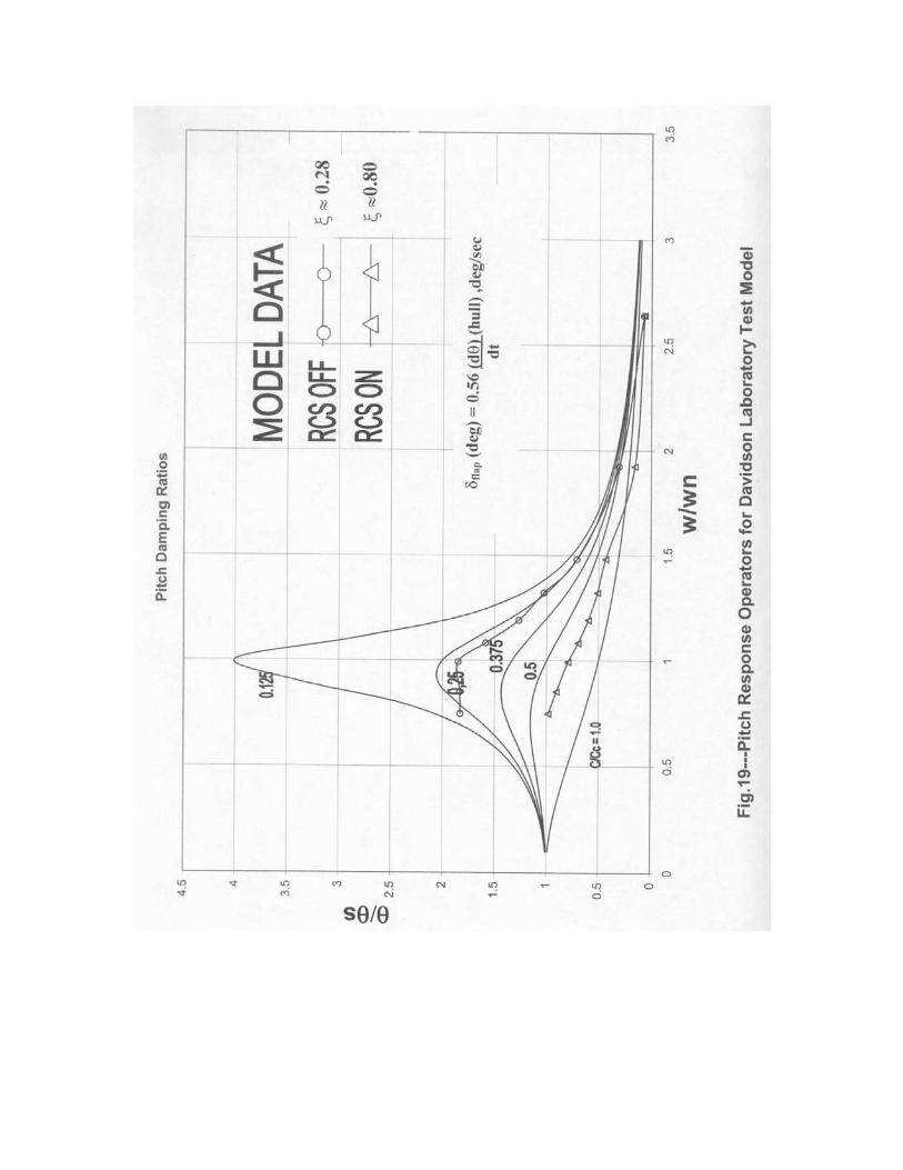
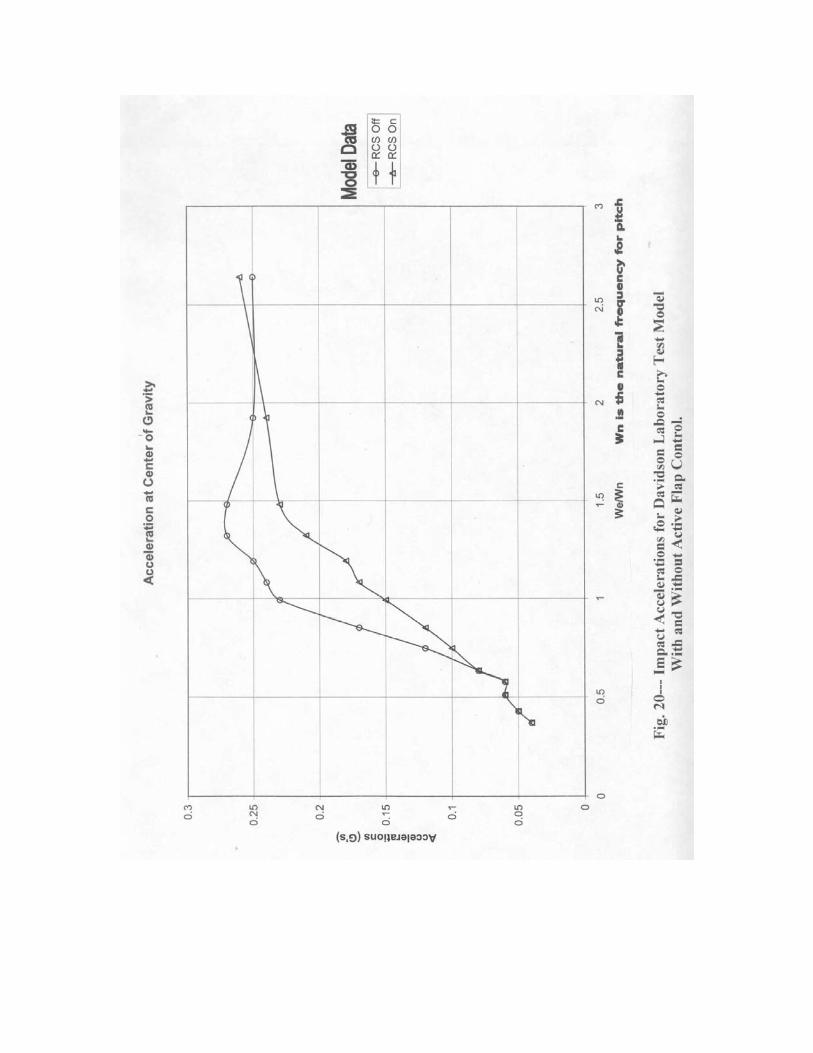
ξ = 1.00. The agreement between these simplistic results and the pitch data for the coupled motion, flap controlled planing hull is again reasonably good. Similar conclusions are observed in Fig.16 for the heave motions with active flap control. In this case the active flap appeared to increase the heave damping ratio to ξ = 0.75. The curve from Figure 14 for ξ = 0.75 is also plotted on Fig. 16. It seems to represent the data quite well These observations are to be taken merely as interesting results and, for the time being, should not be generalized in their potential application. Davidson Laboratory Model Tests of Active Flap Controlled Planing Craft The Davidson Laboratory recently conducted model tests to determine the effectiveness of active transom flaps in attenuating the motions and accelerations of planing hulls in head waves. The tests were not unlike those described in Ref.9 where the magnitude of flap deflection was linearly dependant upon the angular pitch velocity of the model. As stated previously such a control system increases the pitch damping of the hull that, in turn, attenuates the motions of the hull in waves. A sketch of the test model is shown in Fig.17. The principal dimensions are : LWL------------------4.58 ft. Transom Beam------1.12 ft. Deadrise Angle------20 deg. Displacement--------52 lbs. Natural pitch period--0.65 sec. Natural heave period—0.64 sec The transom flaps (one on each side of deadrise bottom) were full span; had a chord of .05 ft; were pivoted at their leading edges that were located at the aft end of the hull transom; and had a range of deflections equal to ± 10 deg. An electric motor, mounted in the hull model, rotated a cam that, in turn, oscillated a rod attached to each flap. The rod motions caused the flaps to deflect up or down as directed by the signal from the angular rate gyro. This gyro was located in the forward part of the hull. Its output signal was amplified, sent to a signal conditioner, and then to the flap drive motor.( Fig. 17) The gain of the amplifier was adjusted to deflect the transom flaps 0.56 deg. for 1.0 deg./sec of angular velocity. All tests were conducted at a speed of 16 ft./sec in regular waves having a height of 1.5 in. and periods that varied from 1 to 4 seconds. Tests were made without and then with the control system activated. Measurements were made of the drag; time histories of the pitch, heave, angular rate gyro, flap deflection, accelerations at the LCG and bow, and encountered wave height. The data were reduced to RAO’s (heave amplitude/wave amplitude; and model pitch angle/wave slope) and presented in Figures 18 and 19 as a function of the ratio of wave encounter frequency/ natural frequency of model. Data are plotted for the controlled and uncontrolled conditions. The RMS CG acceleration data are presented in Fig. 20 for both the controlled and uncontrolled conditions. It is evident that, at the resonant condition, the pitch motions with active flap control are approximately 50% of those for the uncontrolled hull. The heave motions
with active control are nearly 70% of the values without control. Comparing these RAOs with the single degree of freedom response curves taken from Fig. 14. The following observations are made: Pitch Motions:. Assuming a pitch damping ratio of ξ≈ 0.28 for the uncontrolled model, it is seen that the present model data essentially agree with the RAOs obtained from the single degree of freedom results plotted in Fig.14.for a pitch damping ratio ξ ≈ 0.28. The RAOs for the active flap controlled model have all the characteristics of a critical damping where ξ ≈ 0.80. Heave Motions: The uncontrolled model heave RAOs are compared with the single of freedom results taken from Figure 14. It appeared that the heave damping ratio for this configuration was ξ ≈ 0.30. The active flap control increases the effective heave damping to a value of ζ ≈ 0.40. Hence, the pitch velocity control of the flap has a greater beneficial effect on pitch motions than on heave motions.. Accelerations: Fig. 20 plots the RMS acceleration data as a function of the ratio of wave encounter frequency to natural frequency. It is seen, that at resonant frequency, the accelerations are reduce by approximately 65 % when the control system is activated. Resistance in Waves: While these data are not included in this presentation, it was observed that the hull resistance in waves was slightly decreased when the flap control was activated. This is consistent with the reduction in motions achieved with the control system activated. Conclusions
An active transom mounted flap control system is most effective in reducing the motions and accelerations of planing craft operating in head waves. Using the output from a pitch angular velocity sensor to control the
flap deflection is shown to be a very effective and simple way to reduce hull motions and accelerations. This control system increases the effective pitch damping of the system. Surprisingly, it appears that, if the natural frequencies and damping
ratios are known, the motions of a damped, linear, single degree of freedom dynamic system subjected to a sinusoidal forcing will provide results which are representative of the motions of a two degree of freedom, controlled, dynamic system. It is cautioned that this result is not yet to be generally applied.
REFERENCES
1. Savitsky, Daniel; Bagnell, Daniel; Basu, Roger: “Viability of Large High-Speed Displacement Hulls” March, 2000. Presented at 23rd Meeting of the U.S.-Japan Marine Facilities Panel of U.S. Japan Cooperative Program in Natural Resources. Tokyo, Japan. May 17 &18, 2000.
2. Ritter, Owen K. and Templeman, Michael T: “High-Speed Sea lift Technology “ Volume 1. NSRDC, Carderock Division. CDNSWC-SD-98. August,1998.
3. Van Mater, Paul R. Jr.; Zubaly, Robert, B.; and Beys, Petros, M.; “Hydrodynamics of High-Speed Ships” Davidson Laboratory, Stevens Institute of Technology Report No.876. October, 1961. 4. Yeh. Hugh, Y.H. “On High-Speed Displacement Forms” SNAME “Marine Technology, July,1965. 5. Carderock Division, NSWC, Bethesda MD. “High–Speed Sealift Technology Development Plan” NSWCCCD-20-TR-2002/06 May 2002. 6. Gawn,R.W.L. and Burrill, L.C., “The Effects of Cavitation on the Performance of a Series of 16 Inch Model Propellers” Trans. INA, Vol. 99,1957. 7. Newton, R.N. and Rader,H.P. “Performance Data of Propellers for High-Speed Craft”. Trans. RINA Vol. 103, 1961. 8. “Principles of Naval Architecture” SNAME, Vol. 3, 1989. 9. Wang Long-Wen. “A Study on Motions of High-Speed Planing Boats with
Controllable Flaps in Regular Waves” International Shipbuilding Progress. Marine Technology Monthly. Vol. 32, No. 365, Jan. 1985 .