On the Road to 10G - Converged Access Platform for HFC ...
16
© 2021, SCTE ® CableLabs ® and NCTA. All rights reserved. 1 On the Road to 10G - Converged Access Platform for HFC & Ultra Long (60+ km) NGPON2 A Technical Paper Prepared for SCTE by Harj Ghuman Principal COX Communications 6305 Peachtree Dunwoody Road, Atlanta, GA, 30328 404-449-4711 [email protected]
Transcript of On the Road to 10G - Converged Access Platform for HFC ...

© 2021, SCTE® CableLabs® and NCTA. All rights reserved. 1
On the Road to 10G - Converged Access Platform for HFC & Ultra Long (60+ km) NGPON2
A Technical Paper Prepared for SCTE by
Harj Ghuman Principal
COX Communications 6305 Peachtree Dunwoody Road, Atlanta, GA, 30328
404-449-4711 [email protected]

© 2021, SCTE® CableLabs® and NCTA. All rights reserved. 2
Table of Contents Title Page Number
1. Introduction .......................................................................................................................................... 3 2. Data Projections .................................................................................................................................. 3 3. ROCML Drivers ................................................................................................................................... 4 4. Raman Optical Communications Module (ROCML) Overview ........................................................... 5
4.1. Optical Wavelengths .............................................................................................................. 6 4.2. ROCML – RMDM Loss Budget .............................................................................................. 7
4.2.1. Optical Amplification .............................................................................................. 7 4.3. Dispersion Management ........................................................................................................ 8
5. COX PON Architecture ..................................................................................................................... 10 5.1. Current COX PON network .................................................................................................. 10 5.2. Proposed COX Next Gen PON network .............................................................................. 10
6. 25G PON ........................................................................................................................................... 11 6.1. 25 Gigabit Symmetric Passive Optical Network (25GS-PON) ............................................. 11 6.2. 25G PON Over ROCML ....................................................................................................... 12
7. Access Network Topology ................................................................................................................. 12 7.1. DOCSIS 4.0 ESD 1.8 GHz Network .................................................................................... 13 7.2. Fiber To The Home (FTTH) Network ................................................................................... 13
8. Conclusion ......................................................................................................................................... 14
Abbreviations .............................................................................................................................................. 15
Bibliography & References.......................................................................................................................... 16
List of Figures
Title Page Number Figure 1 - Twenty Year Downstream Data Projections ................................................................................. 4 Figure 4 - ROCML Optical Wavelengths ....................................................................................................... 6 Figure 5 - ROCML RMDM Loss Budget ....................................................................................................... 7 Figure 6 - Raman Gain Profile ...................................................................................................................... 8 Figure 7 - Pulse Broadening Due to Dispersion............................................................................................ 9 Figure 8 - Max link vs Data Rate ................................................................................................................... 9 Figure 9 - COX XGS-PON Network ............................................................................................................ 10 Figure 10 - ROCML 10G PON Network ...................................................................................................... 11 Figure 11 - 25GS-PON Network ................................................................................................................. 12 Figure 12 - 25G PON Over ROCML Network ............................................................................................. 12 Figure 13 - DOCSIS 4.0 ESD 1.8 GHz Network ......................................................................................... 13 Figure 14 - FTTH ROCML PON Network ................................................................................................... 14

© 2021, SCTE® CableLabs® and NCTA. All rights reserved. 3
1. Introduction As the Cable industry investigates solutions for 10 Gigabits per second (Gbps) subscriber bandwidths and beyond, the convergence of the two main Multiple System Operator (MSO) network topologies in use today, Hybrid Fiber Coax (HFC) and Passive Optical Network (PON), becomes highly desirable. COX’s current access platform, the Optical Communications Module Link Extender (OCML)1, supports protected bi-directional transport of 10G Dense Wavelength Division Multiplexing (DWDM) optics over dual 5 to 60 km fiber links for Remote PHY Devices (RPDs), remote Optical Line Terminal (OLT) uplinks and business services. This paper describes COX’s next generation converged access platform, the ROCML (Raman OCML), that is targeted for 10 Gbps subscriber bandwidth utilizing Data over Cable Service Interface Specification (DOCSIS 4.0) and/or long distance (60+ km) multi-wavelength 10 Gbps Next-Generation Passive Optical Network 2 (NGPON2). Extended Spectrum DOCSIS 4.0 (ESD) usage of a full 1.8GHz Radio Frequency (RF) spectrum requires 25 Gbps optical interfaces at the Remote PHY Device/Remote MAC-PHY Device (RPD/RMD). The ROCML’s innovative combination of Raman, semiconductor and erbium doped fiber amplification (EDFA) transports both multi-wavelength NGPON2 and 25G DWDM optics over 60+ km optical links from the same integrated platform. It provides scalability to meet future bandwidth requirements such as multiwavelength 25G PON and Distributed Access Architectures (DAA) requiring >25G optical signals to RPDs/RMDs. The solution stays in line with COX’s preferred methodology of keeping the outside plant passive. Hitherto, deploying PON over optical links >20 km has been a challenge requiring COX to deploy outside plant remote OLTs, either in cabinets or in clamshell enclosures.
The ROCML’s long distance NGPON2 capability allows OLTs to remain in centralized indoor hub locations, creating a truly passive long distance PON, vastly improving reliability while reducing Op Ex and capital equipment costs. The ROCML’s scalability to multi-wavelength 25G PON ensures a path to a future all Fiber to the home (FTTH network); it also allows for the transport of high capacity Coherent 100G - 400G optical signals, providing a powerful multi-purpose optical access platform for today’s networks and tomorrow’s requirements.
2. Data Projections Figure 1 provides the twenty-year downstream data projections based on a 25 to 30% YoY CAGR. It shows the aggregate link usage for both DOCSIS 4.0 (D4.0) and 10G PON. Current COX RPD node size is approximately 350 homes passed, which with a 60% penetration rate gives approximately 200 subscribers per RPD. 10 Gigabit Symmetrical (XGS) PON deployments utilize 1:64 split (64 homes passed) per PON port, which using an average 60% penetration rates gives approximately 40 subscribers per link. For D4.0 to meet future data growth, node sizes can be reduced, or spectrum added such as in a 2x2 RPD, both requiring upgrades to the plant. 10G PON can meet projected data demand well into the future, with 25G PON meeting demand for the next twenty years. The maximum speed available to subscribers on either D4.0 or PON will be limited to half the link capacity, so with current D4.0 at 200 subscribers per link, maximum available speed will be 5 Gbps till 2027 and beyond that node sizes can be reduced, or spectrum added (2x2 RPD). On the other hand, 10G PON can support 5 Gbps till 2032 and beyond that a transition to 25G PON can be implemented to meet capacity requirements.

© 2021, SCTE® CableLabs® and NCTA. All rights reserved. 4
Figure 1 - Twenty Year Downstream Data Projections
3. ROCML Drivers Some of the main drivers in developing the ROCML concept are given below:
• Long distance 60+ km 10G NGPON2, scalable to 25G PON • 25 Gbps DWDM optical link for ESD 1.8GHz • Optical transport over dual fiber links, switchable from primary to a backup fiber • High system OSNR platform • Coherent Capability 100G - 400G
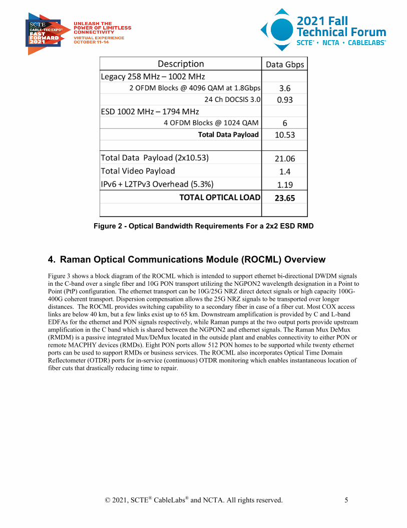
The main challenge was in developing a solution which would provide long reach PON capability over 60 km and the inherent OSNR required to enable this. Since 25G DWDM was also an important requirement, dispersion management became an important factor given the inherent increased dispersion at high data rates. A move from 10 Gbps to 25 Gbps in Distributed Access Architectures (DAA) will be required in the next few years to meet projected subscriber demand. DOCSIS 4.0 ESD 1.8 GHz allows HFC networks to provide much higher bandwidths than current DOCSIS 3.1 which supports only 10 Gbps downstream and 1.5 Gbps upstream. ESD usage up to 1.8 GHz in DOCSIS 4.0 shows downstream rates exceeding 12 Gbps for a 1x1 node and 24 Gbps for a 2x2 node, hence a 25 Gbps optical input to RPDs will be needed. Next generation RMDs supporting ESD 1.8/3 GHz and 25 Gbps optical interfaces could meet projected bandwidth demand for the next decade. 25 Gbps DWDM direct detect Non-return-to-zero (NRZ) is planned to be used over 70 km links in the COX access network with the ROCML, with the assumption that RMDs will be able to support 25 Gbps optical interfaces. Figure 2 provides a breakdown of optical bandwidth requirements for DOCSIS 4.0 ESD 1.8 GHz.
© 2021, SCTE® CableLabs® and NCTA. All rights reserved. 5
Figure 2 - Optical Bandwidth Requirements For a 2x2 ESD RMD
4. Raman Optical Communications Module (ROCML) Overview Figure 3 shows a block diagram of the ROCML which is intended to support ethernet bi-directional DWDM signals in the C-band over a single fiber and 10G PON transport utilizing the NGPON2 wavelength designation in a Point to Point (PtP) configuration. The ethernet transport can be 10G/25G NRZ direct detect signals or high capacity 100G-400G coherent transport. Dispersion compensation allows the 25G NRZ signals to be transported over longer distances. The ROCML provides switching capability to a secondary fiber in case of a fiber cut. Most COX access links are below 40 km, but a few links exist up to 65 km. Downstream amplification is provided by C and L-band EDFAs for the ethernet and PON signals respectively, while Raman pumps at the two output ports provide upstream amplification in the C band which is shared between the NGPON2 and ethernet signals. The Raman Mux DeMux (RMDM) is a passive integrated Mux/DeMux located in the outside plant and enables connectivity to either PON or remote MACPHY devices (RMDs). Eight PON ports allow 512 PON homes to be supported while twenty ethernet ports can be used to support RMDs or business services. The ROCML also incorporates Optical Time Domain Reflectometer (OTDR) ports for in-service (continuous) OTDR monitoring which enables instantaneous location of fiber cuts that drastically reducing time to repair.

© 2021, SCTE® CableLabs® and NCTA. All rights reserved. 6
C Band
DWDM
2 x 2Splitter
C/LBand
DWDM
WDM
WDM
DWDM
Ethernet & NGPON2 UP
SW
OTDR
20 DS CHs
20 US CHs
Primary
Secondary
RMDM
5 to 70km
ROCML
NGPON2 DSNGPON2 DS
NGPON2 UP
10G-PON λmOLT
MUX
WDM
DS
L Band EDFA
C Band EDFAEthernet DS
Raman Pump
RMD25G
10G-PON λmOLT
25G100/400G
1: 64 PON
OTDR
Raman PumpDS
DispersionManagement
100/400G Coherent
1:64 PON
Figure 3 - ROCML Block Diagram
4.1. Optical Wavelengths The ROCML - RMDM is designed for bi-directional transport over a single fiber and the wavelengths utilized are given in Figure 2 below. C-band DWDM is utilized for ethernet transport in both the downstream (DS) and upstream (UP) directions. For the NGPON2 signals, L-band is used in the DS and C-band for the UP signals.
Figure 2 - ROCML Optical Wavelengths
© 2021, SCTE® CableLabs® and NCTA. All rights reserved. 7
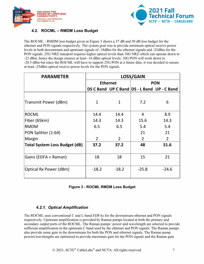
4.2. ROCML – RMDM Loss Budget The ROCML - RMDM loss budget given in Figure 3 shows a 37 dB and 50 dB loss budget for the ethernet and PON signals respectively. The system goal was to provide minimum optical receive power levels in both downstream and upstream signals of -18dBm for the ethernet signals and -25dBm for the PON signals. 25G NRZ transport requires higher optical levels than 10G NRZ which can operate down to -22 dBm, hence the design ensures at least -18 dBm optical levels. 10G PON will work down to -28.5 dBm but since the ROCML will have to support 25G PON at a future date, it was decided to ensure at least -25dBm optical receive power levels for the PON signals.
Figure 3 - ROCML RMDM Loss Budget
4.2.1. Optical Amplification
The ROCML uses conventional C and L-band EDFAs for the downstream ethernet and PON signals respectively. Upstream amplification is provided by Raman pumps located at both the primary and secondary output ports of the ROCML. The Raman pumps’ power and wavelength are selected to provide sufficient amplification in the upstream C band used by the ethernet and PON signals. The Raman pumps also provide some gain in the downstream for both the PON and ethernet signals. The Raman pump powers/wavelengths are optimized to provide maximum gain for the PON signals and the Raman gain
PARAMETER
DS C Band UP C Band DS - L Band UP - C Band
Transmit Power (dBm) 1 1 7.2 6
ROCML 14.4 14.4 4 8.9Fiber (65km) 14.3 14.3 15.6 14.3RMDM 6.5 6.5 5.4 5.4PON Splitter (1:64) 21 21Margin 2 2 2 2Total System Loss Budget (dB) 37.2 37.2 48 51.6
Gains (EDFA + Raman) 18 18 15 21
Optical Rx Power (dBm) -18.2 -18.2 -25.8 -24.6
LOSS/GAINEthernet PON

© 2021, SCTE® CableLabs® and NCTA. All rights reserved. 8
profile for a 70 km link is given in Figure 4. This shows 21 dB upstream gain for the PON signals which is required to increase the PON loss budget from a typical 29 dB to 50 dB. An 18 dB gain for the upstream ethernet is sufficient to meet the loss budgets given in Figure 3. The Raman pumps also provide downstream gains of 7.5 dB and 5 dB for the ethernet and PON signals respectively.
Figure 4 - Raman Gain Profile
4.3. Dispersion Management
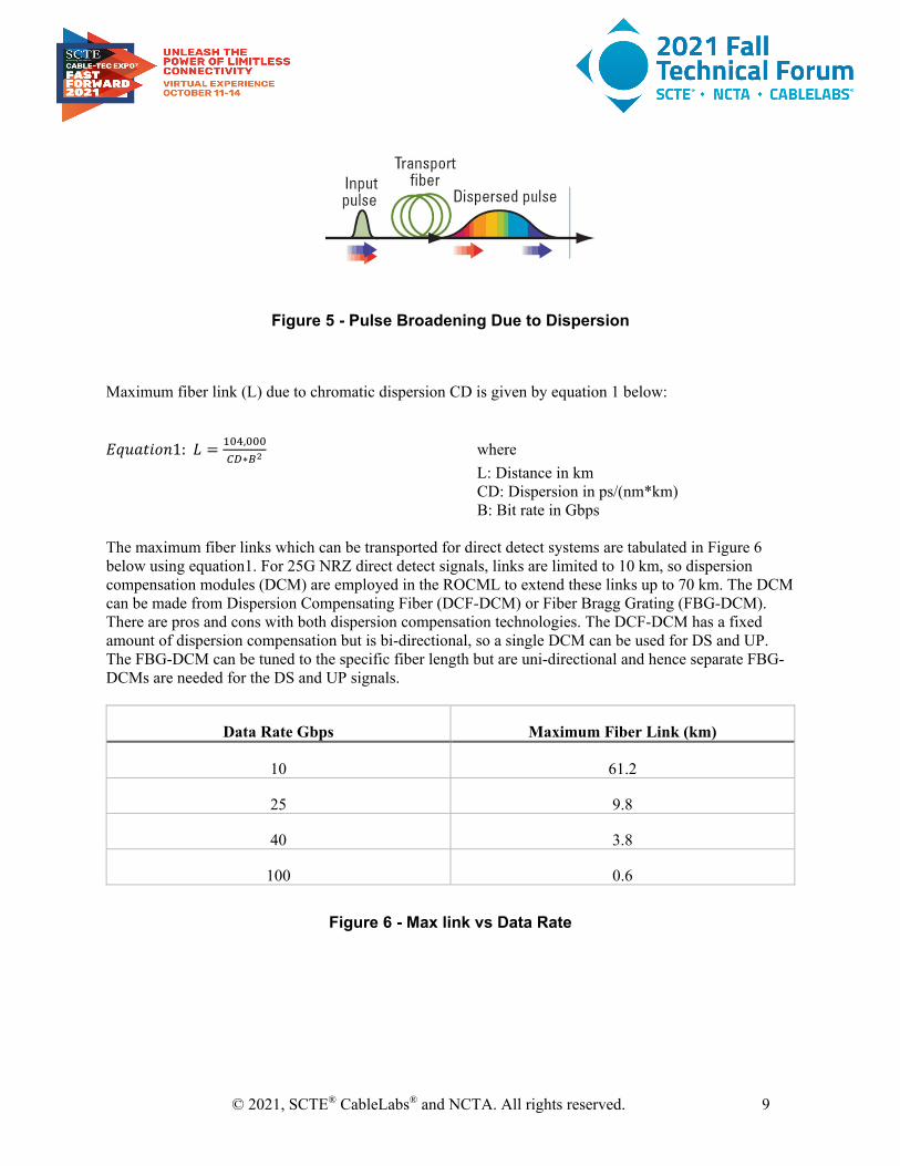
Chromatic dispersion (CD) can cause laser pulses traveling down fibers to spread until they become unrecognizable as depicted in Figure 5. It occurs because different optical wavelengths/frequencies launched from the Tx light source travel at different velocities in a propagating dispersive medium, with the longer wavelengths traveling faster. Chromatic dispersion degrades the transmission quality and limits link distance and hence Dispersion Compensation Modules (DCMs) are added for Intensity Modulated Direct Detect (IM-DD) systems.
© 2021, SCTE® CableLabs® and NCTA. All rights reserved. 9
Figure 5 - Pulse Broadening Due to Dispersion
Maximum fiber link (L) due to chromatic dispersion CD is given by equation 1 below:
𝐸𝐸𝐸𝐸𝐸𝐸𝐸𝐸𝐸𝐸𝐸𝐸𝐸𝐸𝐸𝐸1: 𝐿𝐿 = 104,000
𝐶𝐶𝐶𝐶∗𝐵𝐵2 where
L: Distance in km CD: Dispersion in ps/(nm*km) B: Bit rate in Gbps The maximum fiber links which can be transported for direct detect systems are tabulated in Figure 6 below using equation1. For 25G NRZ direct detect signals, links are limited to 10 km, so dispersion compensation modules (DCM) are employed in the ROCML to extend these links up to 70 km. The DCM can be made from Dispersion Compensating Fiber (DCF-DCM) or Fiber Bragg Grating (FBG-DCM). There are pros and cons with both dispersion compensation technologies. The DCF-DCM has a fixed amount of dispersion compensation but is bi-directional, so a single DCM can be used for DS and UP. The FBG-DCM can be tuned to the specific fiber length but are uni-directional and hence separate FBG-DCMs are needed for the DS and UP signals.
Data Rate Gbps Maximum Fiber Link (km)
10 61.2
25 9.8
40 3.8
100 0.6
Figure 6 - Max link vs Data Rate

© 2021, SCTE® CableLabs® and NCTA. All rights reserved. 10
5. COX PON Architecture COX current PON deployments utilize XGS-PON which is limited to fiber links of 20 km. XGS-PON utilizes L band downstream (1575-1580 nm) and O-band upstream (1260-1280 nm). The upstream wavelengths used have a minimum dispersion which is required since the Optical Network Unit (ONU) uses low-cost direct modulation and the resulting chirp combined with fiber dispersion fiber would cause performance degradation. The ROCML’s innovative design manages fiber dispersion in the upstream, hence C band transmission as defined in the NGPON2 standard can be utilized over longer distances.
5.1. Current COX PON network
The current COX PON architecture (Figure 7) utilizes 10G ethernet uplinks from the current COX access platform OCML1 to feed remote OLTs which are environmentally hardened, passively cooled, strand-mount devices. The OLTs can be mounted in a pedestal or on aerial strand and must be provided with plant power. A distribution split ratio of 1:64 is used which can be dropped to 1:32 to reduce contention.
Figure 7 - COX XGS-PON Network
5.2. Proposed COX Next Gen PON network The proposed PON network with the ROCML is shown in Figure 8, which shows centralized OLTs transported over a primary and back up secondary fiber which could be up to 70 km. Eight C/L band ports on the passive Mux/DeMux (RMDM) located in the outside plant can each support 64 subscribers for a total of 512. Larger split ratio of 1:128 can also be used over shorter links of 40 km (most COX networks) for a total of 1024 subscribers. This network creates a true passive optical network with all active components inside the headend, vastly improving reliability, network downtime and reducing OPEx.

© 2021, SCTE® CableLabs® and NCTA. All rights reserved. 11
Figure 8 - ROCML 10G PON Network
6. 25G PON 25G PON is the next step in PON evolution driven by concrete demand and use cases, including 5th generation mobile network (5G), advanced enterprise applications, and wholesaling services. As shown in Figure 1, COX would need to move to 25 Gbps PON, possibly within this decade to meet projected data demand, especially if 10 Gbps were to be offered to subscribers. 25G PON Delivers a 250% increase in capacity over today’s 10 Gbps XGS-PON and can deliver true 10 Gbps symmetrical services. It leverages mature, high-volume data center optical technology.
6.1. 25 Gigabit Symmetric Passive Optical Network (25GS-PON)
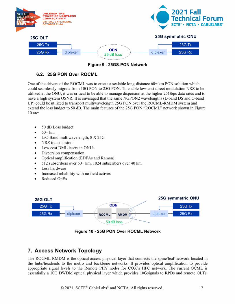
25-Gigabit-capable symmetric passive optical network (25GS-PON) is an optical access network for residential, business, mobile back/mid-haul, and other applications, operating over a point-to-multipoint infrastructure at 25 Gbps downstream and 10 or 25 Gbps upstream. The main features of the 25G PON network shown in Figure 9 are:
• 29 dB loss budget • 20 km maximum fiber link • O-band single wavelength • NRZ transmission • Low cost Directly Modulated Laser diode (DML) in ONUs • No dispersion compensation • No optical amplification
This solution would require remote OLTs as in the current COX XGS-PON deployments with high capacity ethernet uplinks.
© 2021, SCTE® CableLabs® and NCTA. All rights reserved. 12
Figure 9 - 25GS-PON Network
6.2. 25G PON Over ROCML
One of the drivers of the ROCML was to create a scalable long-distance 60+ km PON solution which could seamlessly migrate from 10G PON to 25G PON. To enable low-cost direct modulation NRZ to be utilized at the ONU, it was critical to be able to manage dispersion at the higher 25Gbps data rates and to have a high system OSNR. It is envisaged that the same NGPON2 wavelengths (L-band DS and C-band UP) could be utilized to transport multiwavelength 25G PON over the ROCML-RMDM system and extend the loss budget to 50 dB. The main features of the 25G PON “ROCML” network shown in Figure 10 are:
• 50 dB Loss budget • 60+ km • L/C-Band multiwavelength, 8 X 25G • NRZ transmission • Low cost DML lasers in ONUs • Dispersion compensation • Optical amplification (EDFAs and Raman) • 512 subscribers over 60+ km, 1024 subscribers over 40 km • Less hardware • Increased reliability with no field actives • Reduced OpEx
Figure 10 - 25G PON Over ROCML Network
7. Access Network Topology The ROCML-RMDM is the optical access physical layer that connects the spine/leaf network located in the hubs/headends to the metro and backbone networks. It provides optical amplification to provide appropriate signal levels to the Remote PHY nodes for COX’s HFC network. The current OCML is essentially a 10G DWDM optical physical layer which provides 10Gsignals to RPDs and remote OLTs.

© 2021, SCTE® CableLabs® and NCTA. All rights reserved. 13
The ROCML will transport 25G DWDM signals to Remote MACPHY nodes in a DOCSIS 4.0 ESD 1.8 GHz network and multi-wavelength 10G PON signals which can be transported over extended fiber links of 60+ km, obviating the need for remote OLTs in the outside plant.
7.1. DOCSIS 4.0 ESD 1.8 GHz Network Figure 11 depicts a high level DOCSIS 4.0 ESD (1.8 GHz) network in the COX access networks in a node + x environment. Many devices will need to be upgraded and Figure 11 provides approximate numbers. To get further to an all-Internet Protocol (IP), DOCSIS4.0 10G network, the following need to be upgraded:
• Converged Cable Access Platform (CCAP) to Virtual Controller (or v mac manager) • Converged Interconnect Network (CIN) to 25 Gbps network aggregation (via ROCML) • Nodes need to be upgraded to Remote MAC Devices (RMDs). • Nodes and amps need upgrades to ultra-high-split 1.8 GHz • Taps need to be upgraded to 1.8 GHz (or better) • D4.0 cable modems and gateways capable of ultra-high-split and 1.8 GHz
Figure 11 - DOCSIS 4.0 ESD 1.8 GHz Network
7.2. Fiber To The Home (FTTH) Network
Figure 12 shows how the ROCML - MDM can be utilized to create a true passive PON network and transport 10G signals to subscribers. The biggest Capex in a FTTH network will be trenching fiber to subscriber homes and some upgrades such as:
• CIN needs upgrade to ROCML • Centralized OLTs • ONUs at the subscriber
However, this is a one-time cost and future upgrades such as higher capacity 25G PON will only require changing equipment at the access fiber end points such as OLTs in the headends and ONUs at the subscriber homes. Such a true FTTH network requires less hardware, has no field actives, significantly improves reliability while reducing OPEx.

© 2021, SCTE® CableLabs® and NCTA. All rights reserved. 14
Figure 12 - FTTH ROCML PON Network
8. Conclusion The ROCML - RMDM is a true universal access platform for the foreseeable future. It’s a single integrated optical communication module which can be used for DOCSIS 4.0, long distance symmetrical 10G PON (scalable to 25G PON), 5G and enterprise services. Its innovative design allows for a 10G/25G DWDM direct detect transport over 60+ km fiber links to support RPDs or RMDs and its long-distance 60+ km PON capability creates a true passive optical network. The ROCML will allow COX to seamlessly transition from a DOCSIS 4.0 ESD 1.8 GHz network to an eventual FTTH network.
© 2021, SCTE® CableLabs® and NCTA. All rights reserved. 15
Abbreviations
5G 5th Generation Mobile Network 10G 10 Gbps 25G 25 Gbps 25GS-PON 25 Gigabit Symmetric Passive Optical Network 100G 100 Gbps 400G 400 Gbps bps bits per second CCAP Converged Cable Access Platform CD Chromatic Dispersion CIN Converged Interconnect Network DAA Distributed Access Architectures DCM Dispersion Compensation Module DCF-DCM Dispersion Compensating Fiber DCM DML Directly Modulated Laser diode DS Downstream FBG-DCM Fiber Bragg Grating DCM FTTH Fiber to The Home DOCSIS 3.0 Data Over Cable Service Interface Specifications Version 3.0 DOCSIS 3.1 Data Over Cable Service Interface Specifications Version 3.1 DOCSIS 4.0 Data Over Cable Service Interface Specifications Version 4.0 D4.0 DOCSIS 4.0 DWDM Dense Wavelength Division Multiplexing EDFA Erbium Doped Fiber Amplification ESD Extended Spectrum DOCSIS FTTH Fiber to the Home Gbps Gigabits per second GHz Gigahertz HFC Hybrid Fiber-Coax Hz Hertz IM-DD Intensity Modulated Direct Detect IP Internet Protocol IPv6 Internet Protocol Version 6 L2TPv3 Layer 2 Tunnelling Protocol Version 3 MDM Mux DeMux MSO Multiple System Operator NGPON2 Next-Generation Passive Optical Network 2 NRZ Non-Return-to-Zero OCML Optical Communications Module Link Extender ODN Optical Distribution Network OFDM Orthogonal Frequency-Division Multiplexing OLT Optical Line Terminal OLM Optical-Layer Management ONU Optical Network Unit Op Ex Operating Expenses OSNR Optical to Signal Noise Ratio

© 2021, SCTE® CableLabs® and NCTA. All rights reserved. 16
OTDR Optical Time Domain Reflectometer PON Passive Optical Network PtP Point to Point QAM Quadrature Amplitude Modulation RF Radio Frequency RMD Remote MACPHY Device RMDM Raman Mux DeMux ROCML Raman Optical Communications Module RPD Remote-PHY Device SCTE Society of Cable Telecommunications Engineers UP Upstream XGS 10 Gigabit Symmetrical
Bibliography & References 1. Harj Ghuman, 2017. DWDM Access For Remote-PHY Networks Integrated Optical
Communications Module (OCML). SCTE 2. Harj Ghuman, David Job, 2018. Coherent Access Applications for MSOs. SCTE 3. Harj Ghuman, 2020. Next Gen 25G Access. LightReading Cable Next-Gen Technologies &
Strategies 4. Claudio DeSanti, et al, 2020. Super-PON: An evolution for access networks. Journal of Optical
Communications & Networking 5. Zhengxuan Li, et.al, 2014. Symmetric 40-Gb/s, 100-km Passive Reach TWDM-PON with 53-dB
Loss Budget. Journal of Lightwave Technology