On the Development of the Agile Eye - IEEE Robotics...
9
On the Development of the Agile Eye ..................................................................................... The “Agile Eye” is a high-performance mechanism capable of orienting a camera within a workspace larger than that of a human eye and with velocities and accelerations larger than those of the human eye. The mechanical design, control issues, and experimental results are presented. Keywords: Parallel mechanisms, dynamic control, camera-orienting devices, active vision, kinematic optimization ..................................................................................... amera-orienting devices have been proposed in the recent C years, mainly for use in the field of active vision (see for instance: [1,2,3,4,5,6,7,8]). An account of the main projects addressing the design of robotic heads as well as a good description of the problems to be considered is provided in [9]. In [7] it has been pointed out that, in order to combine images of two cameras in a stereo pair, three degrees of free- dom are required for the orientation of each of the cameras. Indeed, a small range of torsion of each of the cameras about its optical axis is necessary. This motion is accomplished, for example, by the human eyes [7]. Although the prototypes of camera-orienting devices introduced so far have allowed the demonstration of the vision principles and have been used to implement tracking schemes [3], they have mostly been based on classical serial mechanical architectures, which has limit- ed their performance. Hence, the objective of this project was to develop a high- performance camera-orienting device based on a spherical three-degree-of-freedom parallel mechanical architecture. Parallel mechanical architectures have first been introduced in tire testing and motion simulation applications [lo] and later on in robotics (see for instance [11,12]). Parallel mechanisms are character- ized by the fact that the end- effector is connected to the base via multiple kinematic chains and that all the actuators can be located on or close to the base. This leads to high stiffness and load-carrying capaci- ty and to very good dynamic properties since the inertia of the moving parts is considerably reduced. Among other architec- tures, spherical parallel manipulators have received some attention [ 13,14,15]. More recently, families of isotropic spherical parallel manipulators have been obtained through a detailed kinematic analysis [ 161 and the design of the manipu- lator presented here [17] is based on an optimization of these families of mechanisms. This article is arranged as follows: first, the kinematic analysis and optimization of spherical parallel manipulators is reviewed and the optimum architecture presented in [17] is introduced. The mechanical design of the manipulator is then presented and its main properties are described. The dynamic models developed for the manipulator [18] are then discussed and simulation results are presented. Control issues are then introduced and the controller of the agile eye is briefly described. Finally, experimental results are report- ed and analyzed. The mechanism described here aims at orienting a cam- era at high speed. Although the applications for such a device are mainly associat- ed with the tracking of fast objects using a camera, the mechanism could also be December 1996 1070-9932/96/$5.00 0 1996 IEEE IEEE Robotics &Automation Magazine 29
Transcript of On the Development of the Agile Eye - IEEE Robotics...
On the Development of the Agile Eye
..................................................................................... The “Agile Eye” is a high-performance mechanism capable of orienting
a camera within a workspace larger than that of a human eye and with velocities and accelerations larger than those of the human eye. The mechanical design, control issues, and experimental results are presented.
Keywords: Parallel mechanisms, dynamic control, camera-orienting devices, active vision, kinematic optimization .....................................................................................
amera-orienting devices have been proposed in the recent C years, mainly for use in the field of active vision (see for instance: [1,2,3,4,5,6,7,8]). An account of the main projects addressing the design of robotic heads as well as a good description of the problems to be considered is provided in [9].
In [7] it has been pointed out that, in order to combine images of two cameras in a stereo pair, three degrees of free- dom are required for the orientation of each of the cameras. Indeed, a small range of torsion of each of the cameras about its optical axis is necessary. This motion is accomplished, for example, by the human eyes [7]. Although the prototypes of camera-orienting devices introduced so far have allowed the demonstration of the vision principles and have been used to implement tracking schemes [3], they have mostly been based on classical serial mechanical architectures, which has limit- ed their performance.
Hence, the objective of this project was to develop a high- performance camera-orienting device based on a spherical three-degree-of-freedom parallel mechanical architecture. Parallel mechanical architectures have first been introduced in tire testing and motion simulation applications [ lo ] and later on in robotics (see for instance [11,12]). Parallel mechanisms are character- ized by the fact that the end- effector is connected to the base via multiple kinematic
chains and that all the actuators can be located on or close to the base. This leads to high stiffness and load-carrying capaci- ty and to very good dynamic properties since the inertia of the moving parts is considerably reduced. Among other architec- tures, spherical parallel manipulators have received some attention [ 13,14,15]. More recently, families of isotropic spherical parallel manipulators have been obtained through a detailed kinematic analysis [ 161 and the design of the manipu- lator presented here [17] is based on an optimization of these families of mechanisms.
This article is arranged as follows: first, the kinematic analysis and optimization of spherical parallel manipulators is reviewed and the optimum architecture presented in [17] is introduced. The mechanical design of the manipulator is then presented and its main properties are described. The dynamic models developed for the manipulator [18] are then discussed and simulation results are presented. Control issues are then introduced and the controller of the agile eye is briefly described. Finally, experimental results are report- ed and analyzed.
The mechanism described here aims at orienting a cam- era at high speed. Although the applications for such a device are mainly associat- ed with the tracking of fast objects using a camera, the mechanism could also be
December 1996 1070-9932/96/$5.00 0 1996 IEEE IEEE Robotics &Automation Magazine 29

used to control the orientation of mirrors, lasers or any device to be oriented precisely at high speed.
KINEMATIC ANALYSIS AND OPTIMIZATION OF SPHERICAL PARALLEL MECHANISMS The kinematic analysis of a spherical three-degree-of-freedom parallel manipulator and the solution of the inverse kinematic problem associated with this manipulator have been addressed in [14,15]. In [19], polynomial solutions to the direct kinematic problem have been derived. It has been shown in the latter references that this problem leads to a polynomial of degree 8, that expressions can be found for the coefficients of the polynomial and that the maximum number of real solutions to the problem is 8.
The architecture of a general spherical three-degree- of-freedom parallel manipulator is represented schematical- ly in Fig. 1.
The architecture of the manipulator is such that the axes
Figure 1. General architectwe of a spherical three-degree-of-freedorn parallel manipulator and geome fric parame fers.
of all nine revolute joints intersect at one common point which is the center ofrotation of the device. The three motors of the manipulator are fixed to the base. The unit vectors directed along the axes of the actuators are referred to as vec- tors ui, i=1,2,3 while the unit vectors directed along the axes of the revolute joints on the end-effector are referred to as vectors v,, i=1,2,3. Moreover, the orientation of the end-effec- tor with respect to the base is given by a rotation matrix Q and the actuator angles are noted 0 , i = 1,2,3. The link angles of the manipulator are assumed to be the same on each of the legs connecting the end-effector to the base and are noted a, and a,. This is represented in Fig. 1 together with angle y, which is the angle between the axes of the revolute joints on the base and on the end-effector. The base and the end-effec- tor are assumed to be symmetric, i.e., the angle between each of the axes of the revolute joints is the same. Finally, unit vec- tors directed along the axis of the intermediate revolute joint of each of the legs are noted w,, i=1,2,3.
As shown in [14,15], the solution of the inverse kinematic problem of this manipulator is straightforward and leads to a maximum of 8 solutions. The derivation of the solution to
this problem is now briefly recalled. First, a fixed reference frame is defined such that its Z axis makes the same angle with each of vectors U[, i=1,2,3, and such that vector uI is located in the XZ plane. Vectors U,, i=1,2,3, can then be written as
(1) U, = [cosqlsinf3, sinq,sinp, -cosf3]T, i = 1,2,3
where
qi = 2(i-l)d3,i = 1,2,3 ( 2 )
and where p is an angle comprised between 0 and n / 2 defined as
(3)
From Fig.1, it is clear that the following equations hold,
(4) w, e v , =cosa, , i=1,2,3
Expressions of vectors v, can be obtained from matrix Q . Indeed, if a given orientation Q is specified, vectors v, can be computed as
(5) v , = Qv,,,i = 1,2,3
where vr0 is the orientation assumed by vector v, when the end-effector is in its reference orientation. The latter expres- sions of vectors v, as functions of the orientation of the end- effector and expressions of vectors w, as functions of the actuated joint coordinates are then substituted in eqs.(4). This leads to three equations which can be written as
( 6 ) A,T,' +2B,T, +C, = 0, i = 1,2,3
with T, =tan(@, /2) , i=1,2,3 and where the coefficients A,, B, and C, are given, for i=1,2,3, as
Ai = cos a, sin COS qpjx + sin qjvfq)- cos a, cos pui, - sin a, (cos qivi, - sin qivix) - cos a2 (7)
(8) Bi = sin a, [cos P(sin qiuiy + cos q,v, + sin pvjz)]
C, = cos a, sin p(sin qiuiy)- cos a, cos Dui, + sin a, (cos qiuiy - sin qiuix) - cos a2 (9)
in which vj,?, vjy and viz stand for the components of vector vi. Hence, 2 solutions for each of the angles Bi are obtained from eqs. (6) which lead to 8 solutions for the inverse kine- matic problem. Moreover, the different solutions are easily identified by considering the different branches of the 3 quadratic equations.
Equations (4) can then be differentiated with respect to time in order to obtain the velocity equations. As shown in [15], this leads to an equation of the form
30 /€E€ Robotics &Automation Magazine December 1996
where CO is the angular velocity of the end-effector and where vector 6 is the joint velocity vector defined as
Matrices J and K are referred to as the Jacobian matrices of the manipulator [15] and can be written, in invariant form, as
and
(13) K=diag(w, xul.v,,w, xu,.v,,w, X U , . ~ , )
In a landmark paper, Salisbury and Craig [20] have defined the dexterity of a robotic manipulator as the kinematic accu- racy associated with it. Mathematically, they defined the dex- terity as the condition number of the Jacobian matrix of the robot. From the above velocity equation, the dexterity of the spherical three-degree-of-freedom parallel manipulator, noted K, can then be written as
(14) K = ~I-K-' J I ~ ~ I - J - ' 41
where 11*1( denotes the Euclidean norm of its matrix argu- ment, which is defined as
with n the dimension of the square matrix A and with 1 the nx n identity matrix. Moreover, one has
and hence, the reciprocal of the condition number-noted 5 and referred to here as the dexterity of the manipulator-is used instead. One has
1 <=-; k 01<11
Since indices K and 5 are functions of the Jacobian matri- ces, they vary with the configuration of the robot and with the geometric parameters of the robot. A value of 5 equal or close to 1 corresponds to a configuration with a very good kinematic accuracy while a value of 5 equal to 0 is obtained when the manipulator is in a singular configuration. Manipu- lators which can attain at least one configuration where 5 is equal to 1 are referred to as isotropic manipulators and the corresponding configurations are termed isotropic configurations [20].
Since dexterity is a local criterion, i.e., a performance
index which varies with the configuration of the manipulator, a global conditioning index has also been proposed in [21]. This index, noted q, is defined
q=- I, <dW
I, dW (18)
where Wdenotes the workspace of the manipulator. The glob- al conditioning index represents a measure of the overall kinematic performance of the manipulator and is a function of the architecture only.
In [ 161, families of isotropic spherical parallel manipulators
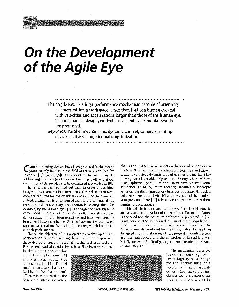
Table 1. Some of the most promising architectures of isotropic spherical three-degree-of-freedom parallel manipulators. Architecture y(deg.) addeg.) ccz(deg.)
A 90 90 90 B 120 120 90 C 105 90 105 D 83 90 90
Table 2. Global conditioning and minimum dexterity over the target workspace (pointing only) for architectures A and D.
Architecture rl Gnu" A 0.81 0.51 D 0.76 0.37
have been obtained using the above expressions of the Jaco- bian matrices and the definition of the dexterity. In other words, isotropic loci in the design space of the robot-i.e., a space defined by the geometric parameters-have been obtained. This has allowed the identification of several isotrop- ic architectures and the most promising of these architectures, which are listed in Table 1, have been investigated here.
First, a workspace analysis has shown that all the architec- tures listed in Table 1 can provide a workspace which satisfies the design constraints, i.e., pointing within a cone of 140" opening with +30° in torsion. Then, computer programs have been written to investigate singularities and global condition- ing. It has been shown that architecture C has a singularity when pointing in the reference direction with an angle of tor- sion of 20". Hence, this architecture was eliminated. Physical dimensions have then been considered. Indeed, it is of utmost importance to avoid mechanical interference of the links throughout the workspace of the manipulator. Moreover, the dimensions of the manipulator should be kept as small as pos- sible in order to minimize the inertia of the moving parts. Because of the link angles associated with them, architectures A and D can be built as two concentric spheres, one for the proximal links of each of the legs and one for the distal links. However, the longer link angles of the proximal links of archi- tecture B do not allow such a simplification and require that all the links be located on concentric spheres. This would result in a larger prototype. Architecture B was therefore also eliminated. Finally, the global conditioning index and the minimum dexterity over the workspace have been considered. The results are given in Table 2 for architectures A and D for
December 1996 IEEE Robotics &Automation Magazine 31
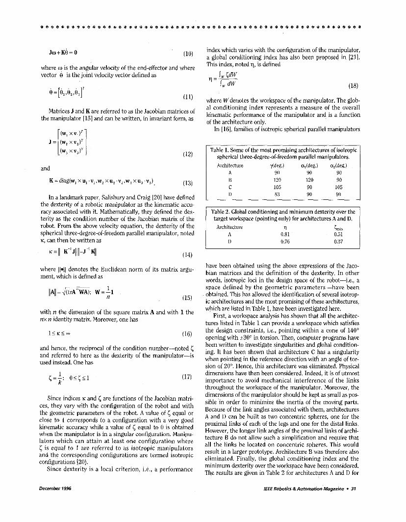
dexterity
Figure 2. Dexterity o f the agile eye over the pointing workspace with zero torsion. The longitude is the angle around the pointing cone while the latitude is the angle measured from the central axis of the cone.
pointing only. Since architecture A has a better global condi- tioning and a larger minimum dexterity, it has been selected as the final kinematic architecture for the prototype. The dexterity of the mechanism is represented graphically as a function of the two pointing angles on the plot shown in Fig. 2 for a torsion angle of zero degree. It can be readily seen that the kinematic accuracy of the mechanism is excellent all over the workspace.
It is also pointed out that, with no torsion, the worst con- figuration in the useful workspace leads to a conditioning of 0.51, which corresponds to a well-conditioned configuration. Undesirable configurations are therefore completely eliminat- ed from the workspace. Moreover, the inverse kinematic prob- lem associated with this architecture is simplified. Indeed, the general solution given in eq.(6) can be written, in this partic- ular case, as
Finally, an additional property of the architecture chosen here has been discussed in [22] . Indeed, with this special architecture (all angles at 90 degrees), the direct kinematic problem simplifies drastically and a simple closed-form solu- tion is obtained. This is useful since this solution can easily be implemented in a controller.
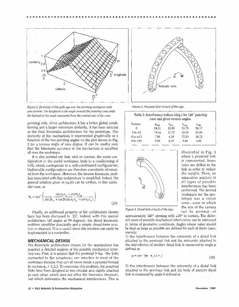
MECHANICAL DESIGN The kinematic architecture chosen for the manipulator has required a detailed analysis of the possible mechanical inter- ferences. First, it is noticed that the proximal links-the links connected to the actuators-can interfere in most of the workspace because they can all move inside a pyramid formed by vectors U,, i=1,2,3. To overcome this problem, the proximal links have been designed as two circular arcs rigidly attached to each other, which does not affect the kinematic structure, but which minimizes the mechanical interferences. This is
Figure 3. Proximal link of each of the legs.
Table 3. Interference indices (deg.) for 140" pointing cone and given torsion angles.
Torsion Pmm Frnm hmm ~ r n m 0 24.31 15.80 35.79 26.07
0 to t 5 18.84 11.37 32.96 23.09 0 to c15 7.88 4.38 25.35 16.72 0 to k 3 0 0.00 0.00 6.46 5.85
illustrated in Fig. 3 where a proximal link is represented. Some holes are drilled in the link in order to reduce the weight. Then, an exhaustive analysis of all types of possible interferences has been performed. The desired workspace for the pro- totype was a vision cone-cone in which
I ' the axis of the camera can be pointed-of Figure 4. Disfal link of each of fhe legs.
approximately 140" opening with c30" in torsion. The differ- ent cases of possible mechanical interference can be expressed in terms of geometric conditions. Angles whose value should be kept as large as possible are defined for each of these cases, namely: 1) the interference between the extremity of a distal link attached to the proximal link and the extremity attached to the end-effector of another distal link is measured by angle p defined as
2) the interference between the extremity of a distal link attached to the proximal link and the body of another distal link is measured by angle 6 defined as
32 0 IEEE Robotics &Automation Magazine December 1996
3) the interference between the vectors defined along the rigid joint connecting the two arcs composing a proximal link, for two different proximal links is measured by angle h defined as
4) finally, the interference between the axis of the camera and the vector along the joint of the two arcs composing a proxi- mal link-which does not represent a mechanical interfer- ence but rather a case in which the links would appear in the cone of vision of the camera-can be measured by angle E, defined as
e = cos-'[(v, +v, +v3).(ut x WJ]
where one has, in each of the above conditions, i,j=1,2,3. A computer program has been written to compute the
above quantities and to determine the configuration in which they are minimal. Some results are given in Table 3 . As shown in this table, maximum torsion cannot always be obtained near the boundary of the pointing workspace.
The most critical configurations obtained from the inter- ference analysis have been studied which led to the design of the distal links. It was found that reducing the width of these links improved the workspace by reducing mechanical inter- ferences. The resulting distal link is illustrated in Fig. 4.
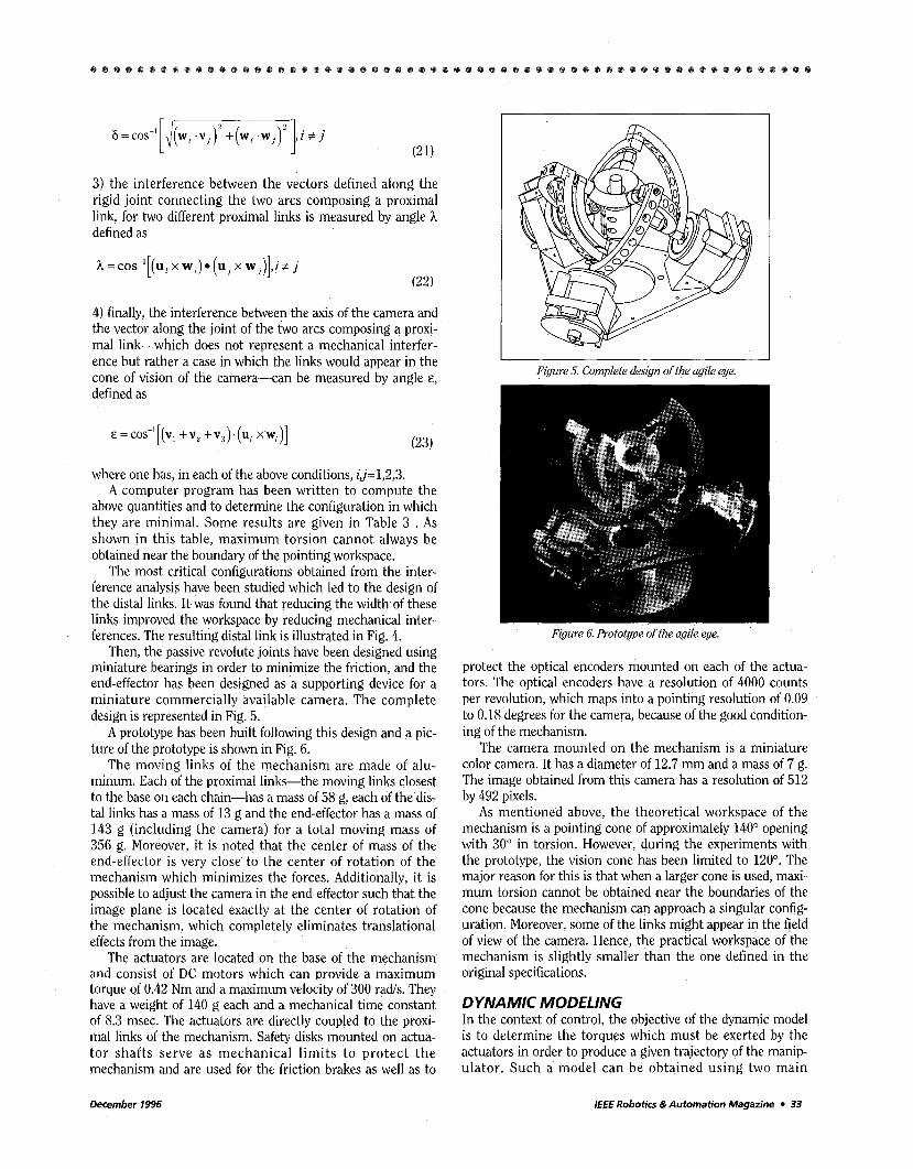
Then, the passive revolute joints have been designed using miniature bearings in order to minimize the friction, and the end-effector has been designed as a supporting device for a miniature commercially available camera. The complete design is represented in Fig. 5.
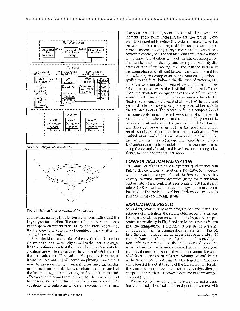
A prototype has been built following this design and a pic- ture of the prototype is shown in Fig. 6.
The moving links of the mechanism are made of alu- minum. Each of the proximal links-the moving links closest to the base on each chain-has a mass of 58 g, each of the dis- tal links has a mass of 13 g and the end-effector has a mass of 143 g (including the camera) for a total moving mass of 356 g. Moreover, it is noted that the center of mass of the end-effector is very close to the center of rotation of the mechanism which minimizes the forces. Additionally, it is possible to adjust the camera in the end-effector such that the image plane is located exactly at the center of rotation of the mechanism, which completely eliminates translational effects from the image.
The actuators are located on the base of the mechanism and consist of DC motors which can provide a maximum torque of 0.42 Nm and a maximum velocity of 300 rads. They have a weight of 140 g each and a mechanical time constant of 8.3 msec. The actuators are directly coupled to the proxi- mal links of the mechanism. Safety disks mounted on actua- tor shafts serve as mechanical limits to protect the mechanism and are used for the friction brakes as well as to
I
Figure 5. Complete design of the agile eye.
Figure 6. Prototype of the agile eye.
protect the optical encoders mounted on each of the actua- tors. The optical encoders have a resolution of 4000 counts per revolution, which maps into a pointing resolution of 0.09 to 0.18 degrees for the camera, because of the good condition- ing of the mechanism.
The camera mounted on the mechanism is a miniature color camera. It has a diameter of 12.7 mm and a mass of 7 g. The image obtained from this camera has a resolution of 512 by 492 pixels.
As mentioned above, the theoretical workspace of the mechanism is a pointing cone of approximately 140" opening with 30" in torsion. However, during the experiments with the prototype, the vision cone has been limited to 120". The major reason for this is that when a larger cone is used, maxi- mum torsion cannot be obtained near the boundaries of the cone because the mechanism can approach a singular config- uration. Moreover, some of the links might appear in the field of view of the camera. Hence, the practical workspace of the mechanism is slightly smaller than the one defined in the original specifications.
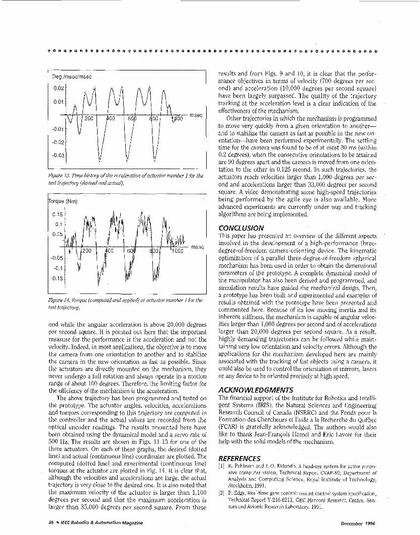
DYNAMIC MODELING In the context of control, the objective of the dynamic model is to determine the torques which must be exerted by the actuators in order to produce a given trajectory of the manip- ulator. Such a model can be obtained using two main
December 1996 IEEE Robotics &Automation Magazine 33
I I I I I I I I 1 I I I I I I I
VME Master VME Slave Analog Power Amplifier I C40 Motherboard And Diaital 110 Board And Diqital Interface
I I I I I I I I I I I
Axis 1 DC Motor Encoder -
Brake .-
Axis 2 j Encoder - I
Brake - I DC Motor- j
I
Figure Z Controller of the agile eye.
Ezgure 8. Schematic representation of the trajectory.
approaches, namely, the Newton-Euler formulation and the Lagrangian formulation. The former is used here-similarly to the approach presented in [14] for the static model-i.e., the Newton-Euler equations of equilibrium are written for each of the moving links.
First, the kinematic model of the manipulator is used to determine the angular velocity as well as the linear and angu- lar accelerations of each of the links. Then, the Newton-Euler equations are written for each of the 7 moving rigid bodies of the kinematic chain. This leads to 42 equations. However, as it was pointed out in [14], some simplifying assumptions must be made on the non-working forces since the mecha- nism is overconstrained. The assumptions used here are that the free-rotating joints connecting the distal links to the end- effector cannot transmit torques, i.e., that they are equivalent to spherical joints. This finally leads to a linear system of 42 equations in 42 unknowns which is, however, rather sparse.
The solution of this system leads to all the forces and moments at the joints, including the actuator torques. How- ever, it is important to reduce this system of equations so that the computation of the actuated joint torques can be per- formed without inverting a large linear system. Indeed, in a context of control, only the actuated joint torques are relevant and computational efficiency is of the utmost importance. This can be accomplished by considering the free-body dia- grams of each of the moving links. For instance, because of the assumption of a ball joint between the distal link and the end-effector, the component of the moment equation- applied to the distal link-in the direction of vector w, will allow the determination of one of the components of the interaction force between the distal link and the end-effector. Then, the Newton-Euler equations of the end-effector can be solved directly since only 6 unknowns remain. Finally, the Newton-Euler equations associated with each of the distal and proximal links are easily solved, in sequence, which leads to the actuator torques. The procedure for the computation of the complete dynamic model is thereby completed. It is worth mentioning that, when compared to the initial system of 42 equations in 42 unknowns, the procedure outlined above- and described in detail in [18]-is far more efficient. It requires only 36 trigonometric function evaluations, 790 multiplications and 13 divisions. Moreover, it has been imple- mented and tested using independent models based on a Lagrangian approach. Simulations have been performed using the dynamical model and have been used, among other things, to choose appropriate actuators.
CONTROL AND IMPLEMENTATION The controller of the agile eye is represented schematically in Fig. 7. The controller is based on a TMS320-C40 processor which allows the computation of the inverse kinematics, velocity inversion, inverse dynamics (using the formulation outlined above) and control at a servo rate of 500 Hz. A servo rate of 1000 Hz can also be used if the dynamic model is not included in the control algorithm. Both modes are readily available in the experimental set-up.
EXPERIMENTAL RESULTS Several trajectories have been programmed and tested. For purposes of illustration, the results obtained for one particu- lar trajectory will be presented here. This trajectory is repre- sented schematically in Fig. 8 and can be described as follows [23] (the manipulator is originally at rest in the reference configuration, i.e., the configuration represented in Fig. 5): first, the pointing axis of the camera is tilted at an angle of 40 degrees from the reference configuration and stopped (por- tion 1 of the trajectory). Then, the pointing axis of the camera is rotated around the reference pointing axis and three com- plete revolutions are performed while maintaining the angle of 40 degrees between the reference pointing axis and the axis of the camera (portions 2 , 3 and 4 of the trajectory). The cam- era is brought to rest at the end of the last revolution. Finally, the camera is brought back to the reference configuration and stopped. The complete trajectory is executed in approximately 1 second (1.025 s).
For each of the portions of the trajectory, the angles defin- ing the latitude, longitude and torsion of the camera with
34 * IEEE Robotics &Automation Magazine December 1996

IO00
800
600
400
200
time (s)
(deg/s/s)
0 0.2 0.4 0.6 0.8 1 time (s)
Figure 9. Magnitude of the angular velocity vector of the camera for the test trajectory. the test trajectory.
Figure 10. Magnitude of the angular acceleration vector of the camera for
Degrees
msec
I Deg./msec
I
Figure 11. Time history of the position of actuator number 1 for the test trajectory (desired and actual).
Figure 12. Time history of the velocity of actuator number 1 for the test tra- jectory (desired and actual).
respect to the reference configuration are interpolated using a polynomial of degree 5 defined as follows:
where @(f) represents the evolution of angle on the given portion of the trajectory, 4j and $are the initial and final val- ues of the angle for this portion, t is the real time and T is the duration of the portion of the trajectory. FunctionsftlT) is the polynomial of degree 5 written as
(25) S ( X ) = ax5 + bx4 + C X ~ + bX2 + e ~
with
(26)
(27)
(28)
a=6-3(i1 +S,)+1/2(S, - S I )
b=-15+8S, +7S, +3/2S, -S,
~ = 1 0 - 6 ~ , -4S, -3 /2S, +1/2S,
d = 1/ 2S,
where k, and ,3.’, are the normalized velocity and accelera- tion at the beginning of the given portion of the trajectory while i f and i f are the normalized velocity and accelera- tion at the end of the portion of the trajectory. In terms of the real initial and final velocity and acceleration, one has
where 4 l and 4, are the initial and final velocities and s , = - - - L .. T 2 & s - T26,
f -- (a, - a t ) ’ (af -a r ) (32)
where& and &are the initial and final accelerations. The polynomial described above is used in order to provide
continuity of the angles as well as their velocities and acceler- ations. The same equations are applied to the longitude, lati- tude and torsion angles, generically referred to as 4 in the above equations. In the test trajectory presented here, torsion was kept at zero degrees during the whole trajectory.
In order to give an idea of the resulting trajectory for the camera, the magnitude of the angular velocity vector and of the angular acceleration vector of the camera are plotted in Figs. 9 and 10. For most of the trajectory, the magnitude of the angular velocity is in the order of 1,000 degrees per sec-
December 1996 lEEE Robotics &Automation Magazine 35
Degimsecimsec I
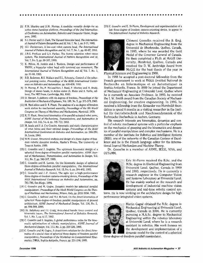
Figure 13. Time history of the acceleration o f actuator number 1 for the test trajectory (desired and actual).
orque (Nm) I
Figure 14. Torque (computed and applied) at actuator number 1 for the test trajectory.
ond while the angular acceleration is above 20,000 degrees per second square. It is pointed out here that the important measure for the performance is the acceleration and not the velocity. Indeed, in most applications, the objective is to move the camera from one orientation to another and to stabilize the camera in the new orientation as fast as possible. Since the actuators are directly mounted on the mechanism, they never undergo a full rotation and always operate in a motion range of about 100 degrees. Therefore, the limiting factor for the efficiency of the mechanism is the acceleration.
The above trajectory has been programmed and tested on the prototype. The actuator angles, velocities, accelerations and torques corresponding to this trajectory are computed in the controller and the actual values are recorded from the optical encoder readings. The results presented here have been obtained using the dynamical model and a servo rate of 500 Hz. The results are shown in Figs. 11-13 for one of the three actuators. On each of these graphs, the desired (dotted line) and actual (continuous line) coordinates are plotted. The computed (dotted line) and experimental (continuous line) torques at the actuator are plotted in Fig. 14. It is clear that, although the velocities and accelerations are large, the actual trajectory is very close to the desired one. It is also noted that the maximum velocity of the actuator is larger than 1,100 degrees per second and that the maximum acceleration is larger than 35,000 degrees per second square. From these
results and from Figs. 9 and 10, it is clear that the perfor- mance objectives in terms of velocity (700 degrees per sec- ond) and acceleration (10,000 degrees per second square) have been largely surpassed. The quality of' the trajectory tracking at the acceleration level is a clear indication of the effectiveness of the mechanism.
Other trajectories in which the mechanism is programmed to move very quickly from a given orientation to another- and to stabilize the camera as fast as possible in the new ori- entation-have been performed experimentally. The settling time for the camera was found to be of at most 30 ms (within 0.2 degrees), when the consecutive orientations to be attained are 90 degrees apart and the camera is moved from one orien- tation to the other in 0.125 second. In such trajectories, the actuators reach velocities larger than 1,000 degrees per sec- ond and accelerations larger than 33,000 degrees per second square. A video demonstrating some high-speed trajectories being performed by the agile eye is also available. More advanced experiments are currently under way and tracking algorithms are being implemented.
CONCLUSlON This paper has presented an overview of the different aspects involved in the development of a high-performance three- degree-of-freedom camera-orienting device. The kinematic optimization of a parallel three-degree-of-freedom spherical mechanism has been used in order to obtain the dimensional parameters of the prototype. A complete dynamical model of the manipulator has also been derived and programmed, and simulation results have guided the mechanical design. Then, a prototype has been built and experimented and examples of results obtained with the prototype have been presented and commented here. Because of its low moving inertia and its inherent stiffness, the mechanism is capable of angular veloc- ities larger than 1,000 degrees per second and of accelerations larger than 20,000 degrees per second square. As a result, highly demanding trajectories can be followed while main- taining very low orientation and velocity errors. Although the applications for the mechanism developed here are mainly associated with the tracking of fast objects using a camera, it could also be used to control the orientation of mirrors, lasers or any device to be oriented precisely at high speed.
ACKNOWLEDGMENTS The financial support of the Institute for Robotics and Intelli- gent Systems (IRIS), the Natural Sciences and Engineering Research Council of Canada (NSERC) and the Fonds pour la Formation des Chercheurs et l'aide a la Recherche du Qukbec (FCAR) is gratefully acknowledged. The authors would also like to thank Jean-Franqois Hamel and Eric Lavoie for their help with the solid models of the mechanism.
REFERENCES [I] K. Pahlavan and J.-0. Eklundh, A head-eye system for active purpo-
sive computer vision, Technical Report CVAP-80, Department of Analysis and Computing Science, Royal Institute of Technology, Stockholm, 1991.
[2] P. Edge, Real-time gaze control: mount control system specification, Technical Report Y-216-6211, GEC Marconi Research Centre, Sen- sors and Avionic Research Laboratory, 1991.
36 IEEE Robotics &Automation Magazine December 1996
[3] P.M. Sharkey and D.W. Murray, A modular versatile design for an active stereo hand/eye platform, Proceedings of the 2nd Internation- al Conference on Automation, Robotics and Computer Vision, Singa- pore, 1992.
[4] N.J. Ferrier and J.J. Clark, The Harvard binocular head, Thelnternation- alJournalofPattern Recognition andAI, Vol. 7, No. 1, pp. 9-31,1993.
[5] H.I. Christensen, A low-cost robot camera head, The International JournalofPattern Recognition and&, Vol. 7, No. 1, pp. 69-87, 1993.
[6] J.R.G. Pretlove and G.A. Parker, The Surrey attentive robot vision system, The International Journal of Pattern Recognition and AI,
[7] E. Milios, M. Jenkin and J. Tsotsos, Design and performance of TRISH, a binocular robot head with torsional eye movement, The International Journal of Pattern Recognition and AI, Vol. 7, No. 1,
[8] B.B. Bederson, R.S. Wallace and E.L. Schwartz, Control of the spher- ical pointing motor, Proceedings of the ZEEE International Confer- ence on Robotics andilutornation, pp. 630-636,1993.
[9] D. Murray, F. Du, P. McLauchlan, I. Reed, P. Sharkey and M. Brady, Design of stereo heads, in Active vision (A. Blake and A. Yuille, edi- tors), The MIT Press, Cambridge, MA, 1992.
[lo] D. Stewart, A platform with six degrees of freedom, Proceedings of the Institution ofMechanica1 Engineers, Vol. 180, No. 5, pp. 371-378,1965.
[ll] H. Maccallion and D. T. Pham, The analysis of a six degree of freedom work station for mechanised assembly, Proceedings of fhe 5th World Congress on Theory ofMachines andMechanisms, MontrCal, 1979.
[12] K. H. Hunt, Structural kinematics of in-parallel-actuated robot arms, ASME Journal of Mechanisms, Transmissions, and Automation in Design, Vol. 105, No. 4, pp. 705-712,1983.
[13] H. Asada and J. A. Cro Granito, Kinematic and static characterization of wrist joints and their optimal design, Proceedings of the IEEE International Conference,on Robotics and Automation, pp. 244-250, St. Louis, 1985.
[ 141 W.M. Craver, Structural analysis and design of a three-degree-of-free- dom robotic shoulder module, Master's Thesis, The University of Texas at Austin, 1989.
[15] C. Gosselin and J. Angeles, The optimum kinematic design of a spherical three-degree-of-freedom parallel manipulator, ASME Jour- nal of Mechanisms, Transmissions, and Automation in Des&, Vol.
[16] C. Gosselin and E. Lavoie, On the kinematic design of spherical three-degree-of-freedom parallel manipulators, The International Journal ofRobotics Research, Vol. 12, No. 4, pp. 394-402, 1993.
[17] C. Gosselin and J.-F. Hamel, The agile eye: a high-performance three-degree-of-freedom camera-orienting device, Proceedings of the IEEE International Conference on Robotics and Automation, pp. 781-786, San Diego, 1994.
[18] C. Gosselin and M. Gagne, Dynamic models for spherical parallel manipulators', Proceedings of the Ninth World Congress on the Theo- ry ofMachines andMechanisms, Milano, Italy, pp. 2032-2036, 1995.
[19] C. Gosselin, J. Sefrioui and M.J. Richard, On the direct kinematics of spherical three-degree-of-freedom parallel manipulators of general architecture, ASME Journal OfMechanicaZ Design, Vol. 116, No. 2,
[ZO] J.K. Salisbury and J.J. Craig, Articulated hands: force control and kinematic issues, The International Journal of Robotics Research,
[21] C. Gosselin and J. Angeles, A global performance index for the kine- matic optimization of robotic manipulators, ASME Journal o f MechanicalDesign, Vol. 113, No. 3, pp. 220-226,1991.
(22) C. Gosselin and M. Gagne, A closed-form solution for the direct kine- matics of a special class of spherical three-degree-of-freedom parallel manipulators, Proceedings of the Workshop on Computational Kine- matics, INRIA, Sophia-Antipolis, France, pp. 231-240, 1995.
Vol. 7, NO. 1, pp. 89-107, 1993.
pp. 51-68, 1993.
111, NO. 2, pp. 202-207,1989.
pp. 594-598,1994.
Vol. 1, NO. 1, pp. 4-17, 1982.
[23] C. Gosselin and E. St-Pierre, Development and experimentation of a fast three-degree-of-freedom camera-orienting device, to appear in The International Journal ofRobotics Research.
ClCment Gosselin received the B. Eng. degree in Mechanical Engineering from the Universiti de Sherbrooke, Quibec, Canada, in 1985, where he was awarded the Gold Medal of the Governor General of Canada. He then completed a Ph.D. at McGill Uni- versity, Montrbal, QuCbec, Canada and received the D. W. Ambridge Award from McGill for the best thesis of the year in
Physical Sciences and Engineering in 1988. In 1988 he accepted a post-doctoral fellowship from the
French government to work at INRIA (Institut National de Recherche en Informatique e t en Automatique) in Sophia-Antipolis, France. In 1989 he joined the Department of Mechanical Engineering at UniversitC Laval, QuCbec where he is currently an Associate Professor. In 1993, he received the I. W. Smith award from the Canadian Society of Mechani- cal Engineering, for creative engineering. In 1995, he received a fellowship from the Alexander von Humboldt foun- dation to spend 6 months as a visiting researcher in the Insti- tu t fur Getriebetechnik und Maschinendynamik of the Technische Hochschule in Aachen, Germany.
His research interests are kinematics, dynamics and con- trol of robotic mechanical systems with a particular emphasis on the mechanics of grasping and the kinematics and dynam- ics of parallel manipulators and complex mechanisms. He is a member of the Institute for Robotics and Intelligent Systems (IRIS), one of the networks of the Canadian Centres of Excel- lence and he is the French language editor for the Interna- tional Journal Mechanism undMuchine Theory.
Dr. Gosselin is a member of ASME, IEEE, AIAA, and CCToMM.
Eric St-Pierre received the B.Sc. and the M.Sc. degree in Electrical Engineering from UniversitC Laval, QuCbec, Canada in 1990 and 1993, respectively. He is currently a research engineer in the Computer Vision and Systems Laboratory at UniversitC Laval. He has mainly worked on the research and development of industrial machine vision systems and real-time robotic control sys-
tems. He is now working on the architecture design for high performance integrated vision systems.
Martin Gagni obtained the B.Sc. degree in Mechanical Engineering at UniversitC Laval, Quebec, Canada in 1996. He is currently pursuing a M.A.Sc. degree in Mechanical Engineering within the robotics laboratory at Universitd Laval, where he is a research assistant in robotics. His work focuses on the development and implementation of a dynamic model for the control of a spherical
three-degree-of-freedom parallel manipulator.
December 1996 IEEE Robotics &Automation Magazine 37