On-Road Development of John Deere 6081 Natural Gas Engine · September 2001 • NREL/SR-540-30163...
54
September 2001 • NREL/SR-540-30163 D.L. McCaw and W.A. Horrell Deere & Company John Deere Power Systems 3800 Ridgeway Ave. Waterloo, IA 50704-8000 On-Road Development of John Deere 6081 Natural Gas Engine Final Technical Report July 1999—January 2001 National Renewable Energy Laboratory 1617 Cole Boulevard Golden, Colorado 80401-3393 NREL is a U.S. Department of Energy Laboratory Operated by Midwest Research Institute • Battelle • Bechtel Contract No. DE-AC36-99-GO10337
-
Upload
duongkhanh -
Category
Documents
-
view
223 -
download
0
Transcript of On-Road Development of John Deere 6081 Natural Gas Engine · September 2001 • NREL/SR-540-30163...
September 2001 • NREL/SR-540-30163
D.L. McCaw and W.A. Horrell
Deere & CompanyJohn Deere Power Systems3800 Ridgeway Ave.Waterloo, IA 50704-8000
On-Road Development of JohnDeere 6081 Natural Gas Engine
Final Technical Report
July 1999—January 2001
National Renewable Energy Laboratory1617 Cole BoulevardGolden, Colorado 80401-3393NREL is a U.S. Department of Energy LaboratoryOperated by Midwest Research Institute •••• Battelle •••• Bechtel
Contract No. DE-AC36-99-GO10337
September 2001 • NREL/SR-540-30163
On-Road Development of JohnDeere 6081 Natural Gas Engine
Final Technical Report
July 1999—January 2001
D.L. McCaw and W.A. Horrell
Deere & CompanyJohn Deere Power Systems3800 Ridgeway Ave.Waterloo, IA 50704-8000
NREL Technical Monitor: Mike FraileyPrepared under Subcontract No. XCI-9-18055-03
National Renewable Energy Laboratory1617 Cole BoulevardGolden, Colorado 80401-3393NREL is a U.S. Department of Energy LaboratoryOperated by Midwest Research Institute •••• Battelle •••• Bechtel
Contract No. DE-AC36-99-GO10337

NOTICE
This report was prepared as an account of work sponsored by an agency of the United Statesgovernment. Neither the United States government nor any agency thereof, nor any of their employees,makes any warranty, express or implied, or assumes any legal liability or responsibility for the accuracy,completeness, or usefulness of any information, apparatus, product, or process disclosed, or representsthat its use would not infringe privately owned rights. Reference herein to any specific commercialproduct, process, or service by trade name, trademark, manufacturer, or otherwise does not necessarilyconstitute or imply its endorsement, recommendation, or favoring by the United States government or anyagency thereof. The views and opinions of authors expressed herein do not necessarily state or reflectthose of the United States government or any agency thereof.
Available electronically at http://www.osti.gov/bridge
Available for a processing fee to U.S. Department of Energyand its contractors, in paper, from:
U.S. Department of EnergyOffice of Scientific and Technical InformationP.O. Box 62Oak Ridge, TN 37831-0062phone: 865.576.8401fax: 865.576.5728email: [email protected]
Available for sale to the public, in paper, from:U.S. Department of CommerceNational Technical Information Service5285 Port Royal RoadSpringfield, VA 22161phone: 800.553.6847fax: 703.605.6900email: [email protected] ordering: http://www.ntis.gov/ordering.htm
Printed on paper containing at least 50% wastepaper, including 20% postconsumer waste

i
Table of Contents
1.0. Executive Summary ................................................................................................................. 12.0. Introduction .............................................................................................................................. 3
2.1 Project Participants ................................................................................................................ 32.2 Project Objectives ................................................................................................................. 42.3 Fleet Description & Duty Cycle ............................................................................................ 42.4 Reporting Period ................................................................................................................... 4
3.0. Completion of Laboratory Engine Development (Task #1)..................................................... 53.1 Performance and Emissions Development ............................................................................ 53.2 Durability Testing ................................................................................................................. 5
4.0. Procurement of Prototype Engines (Task #2) .......................................................................... 75.0. Installation of Engines and Fuel Systems (Task #3) ................................................................ 8
5.1 Initial Driveability.................................................................................................................. 86.0. Fleet Operations (Task #4)..................................................................................................... 11
6.1 Mileage Accumulation and Utilization................................................................................ 126.2 Fuel Consumption and Efficiency ....................................................................................... 136.3 Average Speed ..................................................................................................................... 156.4 Fueling Data Collection ...................................................................................................... 156.5 Refuse Hauler Maintenance and Costs ............................................................................... 166.6 Refuse Hauler Fueling Costs ............................................................................................... 196.7 Deere Engine and CNG Fuel System Repairs ..................................................................... 196.8 Driveability and Performance .............................................................................................. 20
7.0. Development of Prototype Engines in Service (Task #5) ...................................................... 228.0. Commercial Engine Configuration and FTP Test (Task #6) ................................................. 23
8.1 Test Preparations.................................................................................................................. 238.2 Performance Results: ........................................................................................................... 24
8.2.1 Emissions Results With Catalytic Aftertreatment:........................................................ 258.2.2 Emissions Results Without Catalytic Aftertreatment.................................................... 26
8.3 Conclusions......................................................................................................................... 288.4 Certification Results............................................................................................................. 28
9.0. Environmental, Safety, and Health Compliance (Task #7).................................................... 2910.0. Future Plans.......................................................................................................................... 29
ii
List of Tables:
Table 6-1. Cumulative Hubodometer Mileage Comparison .......................................................12Table 6-2. Cumulative Engine Hour Comparison.......................................................................12Table 6-3. Comparison of Time in Service for CNG and Diesel Tractors..................................13Table 6-4. WMI CNG Truck Cumulative Fuel Consumption and Economy Data......................13Table 6-5. Maintenance Costs Associated with Repairs ..............................................................16Table 6-6. Maintenance Performed by NGV Ecotrans on CNG Refuse Haulers ........................18Table 6-7. Fuel Cost Calculations ................................................................................................19Table 8-1. Emissions Targets for Development...........................................................................23Table 8-2. Fuel Used for Emissions Testing ................................................................................23Table 8-3. Performance Results from Power Validation .............................................................24
List of Figures:
Figure 6-1. Cumulative Fuel Economy Summary .......................................................................14Figure 6-2. Cumulative Average Speed Summary.......................................................................15Figure 8-1. Torque Curve for 280 Hp John Deere 8.1L Natural Gas Engine ..............................24Figure 8-2. Composite Emissions Results for Engine Equipped with an Oxidation Catalyst .....26Figure 8-3. Composite Emissions Results for the Engine without an Oxidation Catalyst...........27
List of Photos:
Photo 2.1 - Durability Test Engine Installation.............................................................................6Photos 4-1 & 4-2. L.H & R.H views of the John Deere 8.1L Natural Gas Engine........................7Photos 5-1 & 5-2. L.H. & R.H. views of the John Deere 8.1L NG Engine in chassis...................9Photos 5-3 & 5-4. L.H. & R.H. views of CNG Tanks installed on the P320 trash truck chassis
owned by Waste Management chassis ....................................................................................9Photo 5-5. L.H. view of Waste Management trash truck following the retrofit with a 280 HP
John Deere 8.1L CNG engine................................................................................................10
Attachments
Attachment 1. Vehicle Specifications #203Attachment 2. Vehicle Specifications #267Attachment 3. Vehicle Specifications #269Attachment 4. Vehicle Specifications #274

iii
List of Acronyms:
AFUP Alternate Fuels Utilization ProgramBTU British thermal unitCARB California Air Resources BoardCFF clean fuel fleetCFFV clean fuel fleet vehicleCFR Code of Federal RegulationsCITT curb idle transmission torqueCNG compressed natural gasCO carbon monoxideDF deterioration factorDGE diesel gallon equivalentDOE U. S. Department of EnergyDPSG Deere Power Systems GroupEPA Environmental Protection AgencyFTP federal test procedure (for emissions compliance)hp horsepowerHPR high pressure regulatorLEV low emission vehicleLHV lower heating valuempg miles per gallonmph miles per hourNGV natural gas vehicleNMHC non methane hydrocarbonNREL National Renewable Energy LabNOx nitrogen oxideOEM original equipment manufacturerPEC product engineering centerPM particulate matterrpm revolutions per minutescf standard cubic feetSwRI Southwest Research InstituteWMI Waste Management of Irvine

iv
This page intentionally left blank

1
1.0. Executive SummaryThe National Renewable Energy Laboratory (NREL) is the field manager for the U.S.Department of Energy (DOE) Alternative Fuels Utilization Program (AFUP). As a result of acompetitive solicitation, NREL awarded a contract to John Deere and teamed with them to sharethe costs of the field development of a heavy-duty natural gas engine.
The field test was conducted in the California South Coast Air Basin, using four enginesoperating in trash trucks that are part of the Waste Management (WMI) fleet in Orange County.As part of the project, NGV Ecotrans converted four existing trash packers with Peterbilt 320chassis for compressed natural gas (CNG) fuel systems, and re-powered the trucks with Deere’sprototype, spark-ignited 280-hp 8.1 L CNG engines. Two 1999 Volvo trucks with mechanicallycontrolled diesel engines served as diesel control vehicles. These vehicles were field tested byWMI for approximately 12 months in front-loader trash collection in Southern California. Thisvocation subjects the engine to severe service, which is useful for comprehensively testing theengine’s design and validating the engine’s performance against a market-leading diesel enginemodel.
This field development served as a useful step toward commercializing the engine for heavy-duty trucking applications. The core objectives of this program were met or exceeded as follows:
1) The contract called for a minimum of 250 hours durability testing. After meeting the contractrequirements, John Deere continued durability testing for an additional 750 hours at theirexpense.
2) The John Deere 6081 engine power was successfully increased from 250 to 280 HP.
3) The contract called for an engine that could be certified to the 2.5 gm-NOx standard. The JohnDeere engine was successfully certified to the lower 2.0 gm-NOx standard @ 280 HP during thisprogram as follows:
California Air Resources Board (CARB)-Executive Order A-108-22 dated 13 September 2000certifying to the Optional Low NOx 2.0 gm standard- The emission standard and certificationexhaust emission values for this engine family in grams per brake horsepower-hour under theFederal Test Procedure (“FTP”) are:

2
Non-MethaneHydrocarbons
Carbon Monoxide Nitrogen Oxides Particulate Matter
Standard 1.2 15.5 2.0 0.05Certification 0.2 1.0 1.8 0.01
Environmental Protection Agency (EPA) - Certificate Number JDX-CFF LEV -01-01 dated 7September 2000 certifying to:
NOx + NMHC 3.8 gm Clean Fuel Fleet LEV standard - Federal FuelNOx + NMHC 3.5 gm Clean Fuel Fleet LEV standard - California Fuel
The above results were obtained using an oxidation catalyst.
4) Four 1994 Peterbilt trucks owned by WMI were successfully retrofitted with John Deerenatural gas engines.
5) The four retrofitted refuse trucks successfully completed 12 months of in-service fleet use.
6) Three months of mileage and fuel data were gathered for the in-service operations of the fourretrofitted trucks and two control diesel trucks in the same fleet. Over the 3-month datacollection period for which reliable data was collected, the CNG refuse haulers accumulated anaverage of 3,205 miles while operating an average of 442 engine hours. The CNG refuse haulersaveraged 2.90 miles per diesel equivalent gallon (mi/DGE), compared to an average of 2.68mi/DGE exhibited by the diesel controls.
John Deere has now released the newly certified engine for full commercial production, makingit available for original equipment manufacturers (OEM) use for on-highway applications.Additionally, the successful development of a high horsepower, high efficiency, low emissionCNG 6081 Deere engine will provide the basis for further enhancements, such as loweremissions or improved efficiency, and for new programs, like incorporating ion sensingtechnology, speciation of the exhaust constituents, or new market applications.
3
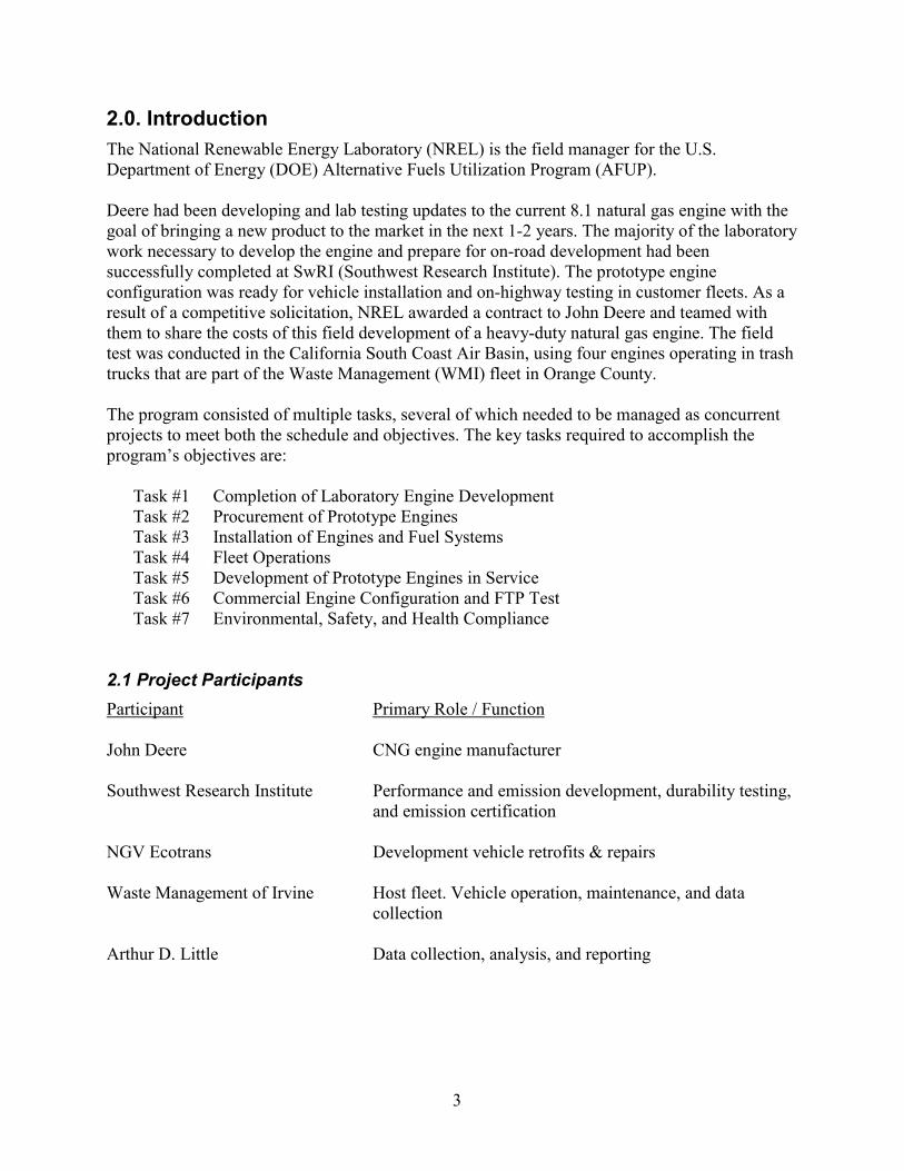
2.0. IntroductionThe National Renewable Energy Laboratory (NREL) is the field manager for the U.S.Department of Energy (DOE) Alternative Fuels Utilization Program (AFUP).
Deere had been developing and lab testing updates to the current 8.1 natural gas engine with thegoal of bringing a new product to the market in the next 1-2 years. The majority of the laboratorywork necessary to develop the engine and prepare for on-road development had beensuccessfully completed at SwRI (Southwest Research Institute). The prototype engineconfiguration was ready for vehicle installation and on-highway testing in customer fleets. As aresult of a competitive solicitation, NREL awarded a contract to John Deere and teamed withthem to share the costs of this field development of a heavy-duty natural gas engine. The fieldtest was conducted in the California South Coast Air Basin, using four engines operating in trashtrucks that are part of the Waste Management (WMI) fleet in Orange County.
The program consisted of multiple tasks, several of which needed to be managed as concurrentprojects to meet both the schedule and objectives. The key tasks required to accomplish theprogram’s objectives are:
Task #1 Completion of Laboratory Engine DevelopmentTask #2 Procurement of Prototype EnginesTask #3 Installation of Engines and Fuel SystemsTask #4 Fleet OperationsTask #5 Development of Prototype Engines in ServiceTask #6 Commercial Engine Configuration and FTP TestTask #7 Environmental, Safety, and Health Compliance
2.1 Project ParticipantsParticipant Primary Role / Function
John Deere CNG engine manufacturer
Southwest Research Institute Performance and emission development, durability testing,and emission certification
NGV Ecotrans Development vehicle retrofits & repairs
Waste Management of Irvine Host fleet. Vehicle operation, maintenance, and datacollection
Arthur D. Little Data collection, analysis, and reporting
4
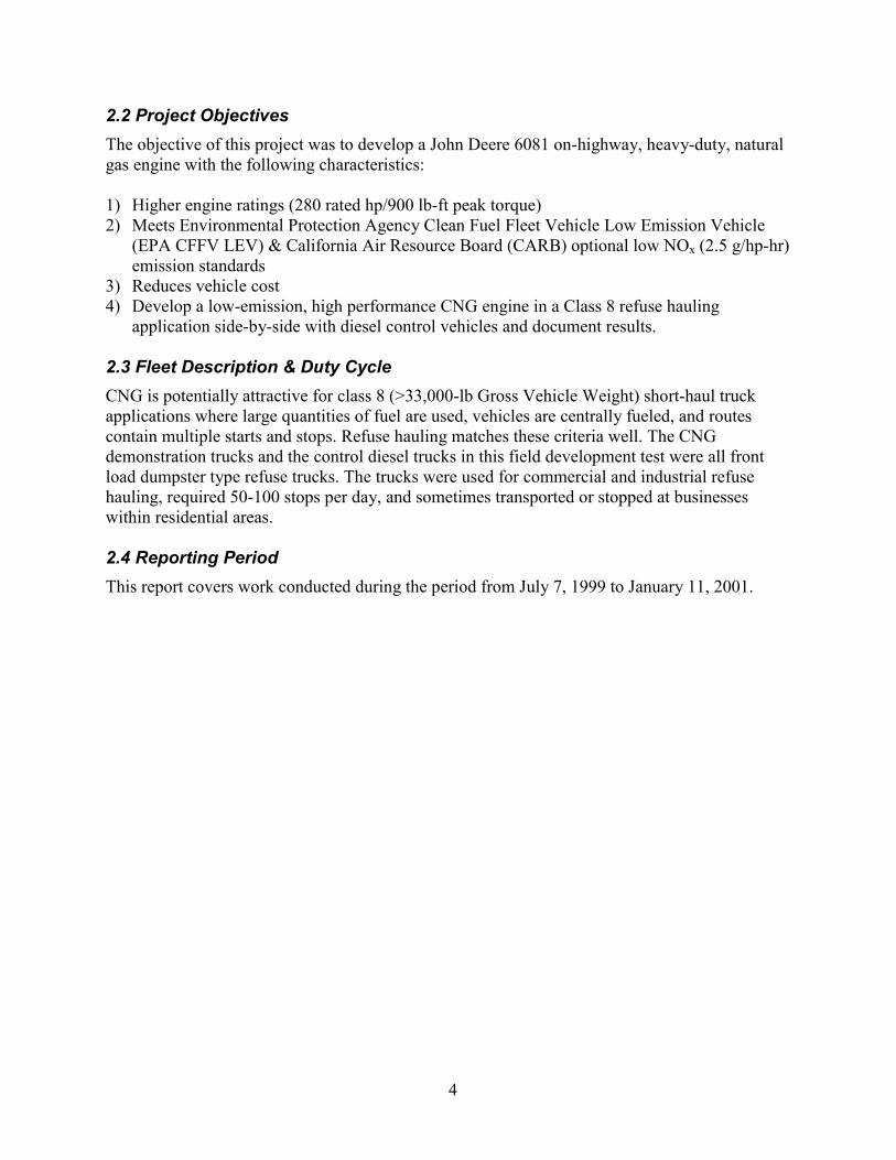
2.2 Project ObjectivesThe objective of this project was to develop a John Deere 6081 on-highway, heavy-duty, naturalgas engine with the following characteristics:
1) Higher engine ratings (280 rated hp/900 lb-ft peak torque)2) Meets Environmental Protection Agency Clean Fuel Fleet Vehicle Low Emission Vehicle
(EPA CFFV LEV) & California Air Resource Board (CARB) optional low NOx (2.5 g/hp-hr)emission standards
3) Reduces vehicle cost4) Develop a low-emission, high performance CNG engine in a Class 8 refuse hauling
application side-by-side with diesel control vehicles and document results.
2.3 Fleet Description & Duty CycleCNG is potentially attractive for class 8 (>33,000-lb Gross Vehicle Weight) short-haul truckapplications where large quantities of fuel are used, vehicles are centrally fueled, and routescontain multiple starts and stops. Refuse hauling matches these criteria well. The CNGdemonstration trucks and the control diesel trucks in this field development test were all frontload dumpster type refuse trucks. The trucks were used for commercial and industrial refusehauling, required 50-100 stops per day, and sometimes transported or stopped at businesseswithin residential areas.
2.4 Reporting PeriodThis report covers work conducted during the period from July 7, 1999 to January 11, 2001.

5
3.0. Completion of Laboratory Engine Development (Task #1)John Deere contracted SwRI to assist in further development and durability testing of the JohnDeere PowerTech 8.1L natural gas engine to meet the goals of the Natural Gas (NG) EngineProgram. John Deere 8.1 L NG engine serial number RG6081H000237 was used for 250 hoursof life testing at SwRI, which was included in this contract. This testing is further described insection 3.2.
3.1 Performance and Emissions DevelopmentIn previous work, several pistons with a range of compression ratios were tested to determine thebest tradeoff in terms of power and efficiency. That work was carried over to this program. Dynowork was performed on the engine to modify the shape of the full load torque curve for the truckapplication. In particular, the torque curve was changed to increase the torque levels at speedsbelow 1600 rpm. This work involved an iterative process of adjusting the fuel-air equivalenceratio, spark timing, and boost pressure control set-points to provide the desired torque output.Emissions measurements were also made to ensure the NOx at the higher torque levels wouldmeet or exceed the 2.5 g/bhp-hr standard requirements.
Dyno work was also conducted to further improve the engine calibration. The boost control tablewas finalized for the desired torque curve, and the waste-gate control table was modified toensure that the engine torque response was proportional to the throttle input across the operatingrange of the engine. The humidity compensation tables were revised for proper operation overthe full range of humidity conditions to prevent misfire tendency. Knock testing was conductedand revised gains for the knock control system were developed as a short-term safeguard againstengine damage from poor quality gas. The commercial engine will include all of these features.
Woodward Governor Co, Fort Collins, CO, manufactures and supplies natural gas engine controlsystems for John Deere. Woodward incorporates the specific calibrations developed by JohnDeere/SwRI for the Deere CNG engines into the control files. Woodward provided the updatedfiles for the previously mentioned revisions in the latest calibration information. Those updatedfiles were then tested at SwRI and found to have the proper correction values.
With the steady state laboratory calibration complete, the next step was to test driveability.Verification of the calibration under transient conditions in an actual vehicle was necessary totruly optimize the calibration. SwRI used a school bus with an updated 8.1 John Deere CNGengine as the driveability vehicle. The initial driveability results were good and this calibrationwas established as the starting point for testing the refuse fleet.
3.2 Durability TestingThe John Deere 8.1L NG engine serial number RG6081H000237 was used for the life testing atSwRI.

6
Photo 2.1 - Durability Test Engine Installation
A photograph of the durability test engine as installed in the test cell is shown in Photo 2.1. Theengine was instrumented to measure power and fuel flow as well as pertinent temperatures andpressures.
The durability test was started on November 15, 1999. A few minor problems were experiencedduring the first 100 hours. At 36 test hours, the waste-gate actuator failed. The actuator wasreplaced and no further problems were noted. At 51 test hours, the exhaust manifold gasket oncylinder #1 was found to be leaking. No damage to the manifold or head was found, so thegasket was replaced and the test continued. At 54 test hours, a slight misfire was noted. Thecause was determined to be a poor connection between the ignition coil and the spark plug boot.This was corrected and no further misfires were noted. The spark plugs were examined, valverecession measurements were conducted, and no significant wear was noted.
The John Deere 8.1L NG engine serial number RG6081H000237 completed the 250 hours of lifetesting without further problems. In addition to the 250 hours that were required and co-fundedas part of this program, this engine was run for another 750 hours of life testing at John Deere’sexpense. Following the 1,000 hours of testing, it was then returned to the John Deere ProductEngineering Center for a complete tear down and final inspection. The tear down and inspectionof the durability engine following 1,000 hours of life testing found it to be in excellent condition.No major problems of any type were found during tear down inspection or during the suppliers’inspection of the key components from this engine.
7
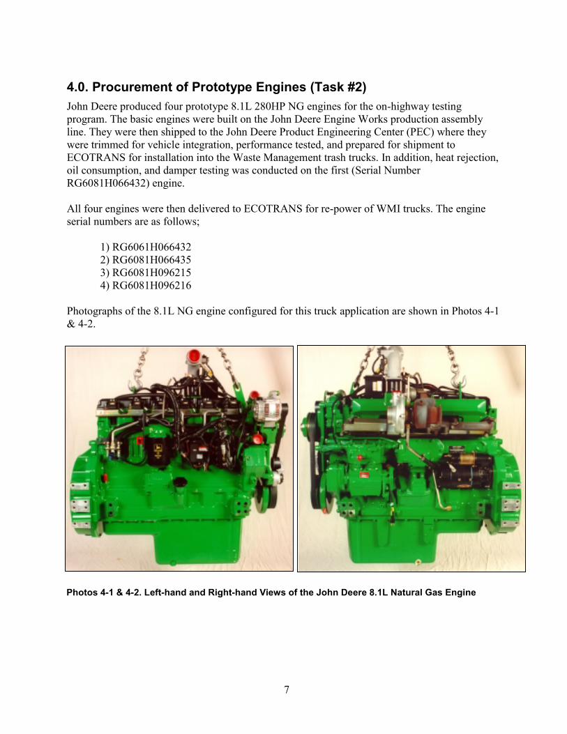
4.0. Procurement of Prototype Engines (Task #2)John Deere produced four prototype 8.1L 280HP NG engines for the on-highway testingprogram. The basic engines were built on the John Deere Engine Works production assemblyline. They were then shipped to the John Deere Product Engineering Center (PEC) where theywere trimmed for vehicle integration, performance tested, and prepared for shipment toECOTRANS for installation into the Waste Management trash trucks. In addition, heat rejection,oil consumption, and damper testing was conducted on the first (Serial NumberRG6081H066432) engine.
All four engines were then delivered to ECOTRANS for re-power of WMI trucks. The engineserial numbers are as follows;
1) RG6061H066432 2) RG6081H066435
3) RG6081H0962154) RG6081H096216
Photographs of the 8.1L NG engine configured for this truck application are shown in Photos 4-1& 4-2.
Photos 4-1 & 4-2. Left-hand and Right-hand Views of the John Deere 8.1L Natural Gas Engine
8
5.0. Installation of Engines and Fuel Systems (Task #3)NGV Ecotrans Group in Los Angles, California was contracted by John Deere to retrofit the fouron-highway test vehicles.
During August 1999, Ecotrans installed a John Deere natural gas engine S/N RG6081H066432into the first of four Peterbilt P320 trash truck chassis owned by WMI. The truck was a 1994model year with 127,853 miles on it. The replaced engine was a Cummins 8.3 L diesel. Inaddition, Ecotrans fitted this vehicle with four natural gas tanks, modified the Allisontransmission to handle higher torque, recored the radiator, and fabricated new engine mounts.Ecotrans also adapted various vehicle systems such as: exhaust, inlet air, and electrical systemsto interface with the new engine.
5.1 Initial DriveabilityThe initial start up of the first vehicle occurred in late August. There were various issuesaddressed at initial start up. Some slight adjustments to the calibration were completed. Thesechanges minimized the high-speed governor surge, and minor fueling changes were made toimprove the tip-in smoothness. After completing these changes, the driveability was consideredto be satisfactory, except in the following areas: 1) The acceleration was not quite what the WMIfleet was looking for, and 2) The transmission shifted late.
During September, Ecotrans and John Deere worked together to resolve the vehicle performanceissues identified during the initial shake-down of the first WMI vehicle. During this process, itwas found that the engine misfired at low vehicle speeds. The problem was found to be due tothe placement of the exhaust exit very close to the engine air intake. The exhaust system wasrevised to prevent re-circulation and the engine ran fine.
Investigation of the transmission performance issue found two separate problems: 1) thetransmission shifted too late, and 2) the transmission "slipped" during the gear three to four shift.A speed sensor on the transmission was found to be disconnected which solved the late shiftproblem, and a loose contact for the lock-up torque converter was found which resolved the"slipping" problem. The transmission then operated properly.
In a continuing effort to increase the low speed performance of the engine, John Deere opted toincorporate a different turbocharger. The development of the new turbocharger and enginecontrol calibrations continued during fleet operation. The details of this work are covered inSection 7.0 of this report.
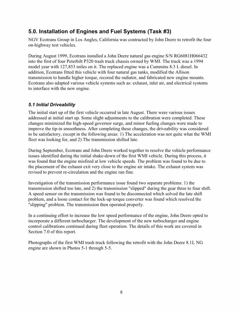
Photographs of the first WMI trash truck following the retrofit with the John Deere 8.1L NGengine are shown in Photos 5-1 through 5-5.

9
Photos 5-1 & 5-2. Left hand and Right hand Views of the John Deere 8.1L NG Engine in Chassis.
Photos 5-3 & 5-4. Left-hand and Right-hand Views of CNG Tanks Installed on the P320 Trash TruckChassis Owned by WMI.
10
Photo 5-5. Left-hand View of WMI Trash Truck Following the Retrofit with a 280 HP John Deere8.1L CNG Engine
After completing all the checks and changes, the results of the driveability test were considered tobe satisfactory. The first vehicle was then delivered to WMI for use in fleet operation. Once thedriveability of the first truck was deemed satisfactory by WMI, the remaining three trucks werescheduled for retrofitting at Ecotrans. All of the trucks were Peterbilt P320 chassis with between125,000 and 135,000 miles on the odometer. Retrofitting of the last truck was completed in March2000.
Installation of all four engines into trucks was completed by Ecotrans on the Peterbilt P320 trucksowned by WMI, as follows:
Started Service in WMI Fleet Engine serial numbers WMI Fleet numbers VIN Numbers
12 Oct 99 RG6061H066432 Truck #269 1XPZL79X1RD706468
31 Jan 00 RG6081H066435 Truck #203 1XPZX70X4SD708612
19 Feb 00 RG6081H096215 Truck #267 1XPZL79XXRD706467
22 Mar 00 RG6081H096216 Truck #274 1XPZX70X0SD708610
The complete Vehicle Specifications sheets for the four trucks are provided as Attachments 1through 4.
11
6.0. Fleet Operations (Task #4)A formal field testing agreement was established between WMI and John Deere. This agreementdefined that ownership of these Pre-certification engines stays with John Deere during the 12-month testing period. It further defined the responsibilities of each party during the testing periodfor parts, repairs, maintenance, and data reports.
A lower tier-subcontract was signed between Arthur D. Little and John Deere for third party datacollection and evaluation. Once all the trucks were retrofitted and full fleet operations began,Arthur D. Little collected data on the four John Deere powered vehicles, and on two similardiesel powered vehicles in the WMI fleet. The two diesel control trucks were 1999 Volvo modelWXLL64 with Volvo VED7300 mechanically controlled engines.
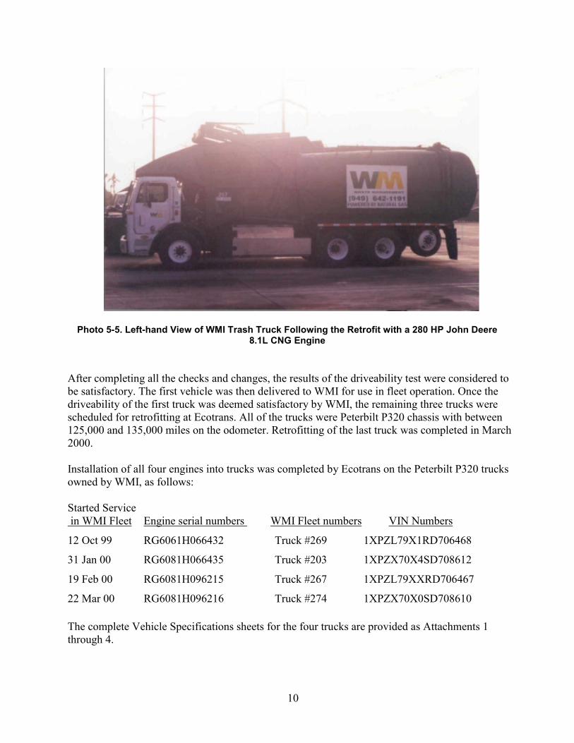
A product support plan was established for the John Deere test vehicles in the WMI fleet. The planwas to have the customer contact DPSG Service directly when problems occurred. This kept theinformation and communication at one common point. Deere Service then analyzed each situationto determine if the problem could be handled by the local Deere dealer or if Ecotrans or DeereEngineering needed to be involved. A flow chart for the product support plan follows:
Customer (WM)
DPSG Service - Tim FrancisToll Free # - Cell Phone - Etc
EngineeringTreptow
Deere DealerCoastline Equip.
Ecotrans
Data entered inDTAC
Arcadis (DataCollection Co.)

12
The following sections present operating data and performance calculations for the programperiod. This data was independently collected and tabulated by Arthur D. Little, Inc.
6.1 Mileage Accumulation and UtilizationThe number of miles and engine hours logged by the trucks differed between CNG and dieseltrucks. This was largely a result of various problems with the re-power process and the use ofolder vehicles and subsequent downtime for the CNG powered vehicles. In general, the CNG anddiesel refuse haulers ran similar routes in terms of duty-cycle and mileage. However, beginningin September 2000, CNG truck #203 ran a route to the City of Mission Viejo, resulting in highermileage and higher average speeds (due to increased highway travel). As of December 4, 2000,WMI entered into an agreement with the City of Mission Viejo to provide refuse removal usingonly CNG-powered haulers. After December 4, 2000, all available CNG trucks were used inMission Viejo, thereby achieving duty-cycle parity among CNG vehicles. The diesel controltrucks operated in Irvine at slightly lower average speeds.
Tables 6-1and 6-2 present comparisons of cumulative hubodometer and engine hour meterreadings for the period of October 5, 2000 to January 11, 2001. It is this time span for whichhubodometer and engine hour data was recorded by Arthur D. Little personnel, and CNG fuelingdata were provided by Pickens Fueling Reports.
Table 6-1. Cumulative Hubodometer Mileage Comparison(5 October 2000–11 January 2001)
WMI Fleet No. #203 #2671 #269 #274 #231 #232
Hubodometer Mileage 3,785 2,332 3,068 3,633 4,865 5,053Percentage of Diesel2 76% 47% 62% 73% NA NA
Table 6-2. Cumulative Engine Hour Comparison(5 October 2000–11 January 2001)
WMI Fleet No. #203 #2671 #269 #274 #231 #232
Engine Hours 438 427 452 452 745 769Percentage of Diesel2 59% 56% 60% 60% NA NA
Table 6-3 presents a comparison of availability between CNG and diesel trucks. This comparisonis based upon data received over the period between October 5, 2000 and January 11, 2001, andutilizes a count of all days for which miles/engine hours were logged, or fueling events wererecorded. The CNG trucks were available for use roughly half of the time that the diesel truckswere utilized. The primary problems with the CNG trucks included transmission overheating and
1 For truck #267, cumulative hubodometer, engine hour, and average speed data are for the cumulative period 5October 2000 – 11 January 2001. Fuel consumption and economy calculations are based upon the period 5 October2000 – 30 November 2000.
2 Based upon comparison to average of two diesel values.
3 Based upon the period 5 October 2000 to 11 January 2001 only.
13
shifting, hydraulic failures, chassis electrical problems, a trash fire in one of the trucks, and ashortage of drivers. Only a small percent to the downtime was related to CNG problems or CNGdevelopment application revisions. A complete listing of the failures is provided in section 6.5 inthis report
Table 6-3. Comparison of Time in Service for CNG and Diesel TractorsWMI Fleet No. #203 #267 #269 #274 #231 #232
Days in Service3 39 35 42 41 77 76Percentage of Diesel2 51% 46% 55% 54% NA NA
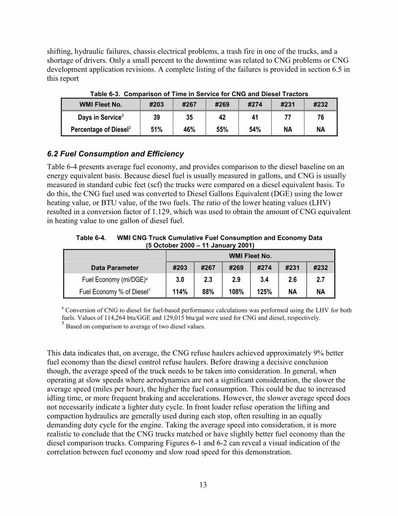
6.2 Fuel Consumption and EfficiencyTable 6-4 presents average fuel economy, and provides comparison to the diesel baseline on anenergy equivalent basis. Because diesel fuel is usually measured in gallons, and CNG is usuallymeasured in standard cubic feet (scf) the trucks were compared on a diesel equivalent basis. Todo this, the CNG fuel used was converted to Diesel Gallons Equivalent (DGE) using the lowerheating value, or BTU value, of the two fuels. The ratio of the lower heating values (LHV)resulted in a conversion factor of 1.129, which was used to obtain the amount of CNG equivalentin heating value to one gallon of diesel fuel.
Table 6-4. WMI CNG Truck Cumulative Fuel Consumption and Economy Data (5 October 2000 – 11 January 2001)
WMI Fleet No.
Data Parameter #203 #267 #269 #274 #231 #232
Fuel Economy (mi/DGE)4 3.0 2.3 2.9 3.4 2.6 2.7Fuel Economy % of Diesel5 114% 88% 108% 125% NA NA
4 Conversion of CNG to diesel for fuel-based performance calculations was performed using the LHV for bothfuels. Values of 114,264 btu/GGE and 129,015 btu/gal were used for CNG and diesel, respectively.5 Based on comparison to average of two diesel values.
This data indicates that, on average, the CNG refuse haulers achieved approximately 9% betterfuel economy than the diesel control refuse haulers. Before drawing a decisive conclusionthough, the average speed of the truck needs to be taken into consideration. In general, whenoperating at slow speeds where aerodynamics are not a significant consideration, the slower theaverage speed (miles per hour), the higher the fuel consumption. This could be due to increasedidling time, or more frequent braking and accelerations. However, the slower average speed doesnot necessarily indicate a lighter duty cycle. In front loader refuse operation the lifting andcompaction hydraulics are generally used during each stop, often resulting in an equallydemanding duty cycle for the engine. Taking the average speed into consideration, it is morerealistic to conclude that the CNG trucks matched or have slightly better fuel economy than thediesel comparison trucks. Comparing Figures 6-1 and 6-2 can reveal a visual indication of thecorrelation between fuel economy and slow road speed for this demonstration.
14
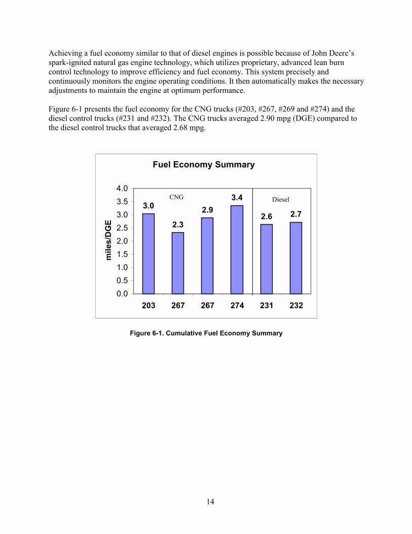
Achieving a fuel economy similar to that of diesel engines is possible because of John Deere’sspark-ignited natural gas engine technology, which utilizes proprietary, advanced lean burncontrol technology to improve efficiency and fuel economy. This system precisely andcontinuously monitors the engine operating conditions. It then automatically makes the necessaryadjustments to maintain the engine at optimum performance.
Figure 6-1 presents the fuel economy for the CNG trucks (#203, #267, #269 and #274) and thediesel control trucks (#231 and #232). The CNG trucks averaged 2.90 mpg (DGE) compared tothe diesel control trucks that averaged 2.68 mpg.
Fuel Economy Summary
3.0
2.3
2.93.4
2.6 2.7
0.00.51.01.52.02.53.03.54.0
203 267 267 274 231 232
mile
s/D
GE
CNG Diesel
Figure 6-1. Cumulative Fuel Economy Summary

15
6.3 Average SpeedFigure 6-2 presents average speed calculations for the CNG trucks and the diesel control trucks,on a cumulative basis. Averaging the data reveals the CNG units averaged 7.2 mph and the dieselcontrol units averaged 6.6 mph.
Average Speed Summary
8.6
5.1
6.88.0
6.5 6.6
0.01.02.03.04.05.06.07.08.09.0
10.0
203 267 267 274 231 232
mile
s pe
r hou
r
Figure 6-2. Cumulative Average Speed Summary
6.4 Fueling Data CollectionCNG Trucks:Early in the demonstration, a lack of driver training/input led to improper fueling practices andincomplete fills. Prior to September 2000, it appeared that about 30%–40% of the CNG fills hadgone unrecorded. The WMI fleet manager said that this was mainly a result of driversunderfilling the CNG units and then returning for unrecorded “topoff” fills. Drivers had beenshuttling the CNG trucks to the City of Irvine CNG station. This light-duty automotive stationhas a low fill rate, resulting in long (20-30 min.) fill times. Since drivers often work long days(11-13 hrs) and are not given overtime to fill the CNG trucks, incomplete fuel fills often resulted.The trucks then run low on fuel partway through the service day, requiring a trip back to thefueling station. These mid-day fills usually went unrecorded.
An improvement was found when Pickens Fuel Corporation programmed the fueling cardreaders to accept four-digit hubodometer values. After a period of driver training, hubodometerdata capture began at the CNG fueling station. The performance calculations in this report arebased on a combination of data collected by Arthur D. Little during WMI site visits, and the fuelreports provided by Pickens.
CNG Diesel

16
Diesel Trucks:Diesel fuel is dispensed at the WMI facility, and tracked using metered reports. These reports arekept on file at WMI, and were provided to Arthur D. Little upon request.
6.5 Refuse Hauler Maintenance and CostsAccording to the August 1999 Testing Agreement between Deere and WMI, WMI wasresponsible for all non-engine and fuel system repairs on the CNG trucks. However, nomaintenance records were provided to this end by WMI. The maintenance data in this report wasprovided by Ecotrans.
Diesel Trucks:Two diesel powered trucks served as diesel comparison units. The diesel trucks were production1999 Volvo units with mechanically controlled engines. No maintenance records were receivedfrom WMI for inclusion in this report. The shop at WMI presumably handled Dieselmaintenance in-house. Due to the lack of diesel maintenance information, no cost comparisoncan be made with that performed on CNG refuse haulers.
CNG Trucks:The CNG trucks were 4-5 years older than the diesel control trucks, and would presumably needmore maintenance. Also more maintenance might be required because of the experimentalnature of the CNG engine. WMI shop staff indicated that very little, if any, maintenance wasperformed on the CNG trucks by WMI. NGV Ecotrans provided records of work performed onthe CNG trucks at their Los Angeles facility. These maintenance and repair events extendedwell beyond engine and fuel system adjustments and replacements.
Table 6-5 presents maintenance costs associated with repair of both engine and fuel-system-related problems and those that were related to other systems.
Table 6-5. Maintenance Costs Associated with Repairs
CNG System Related Other Total
Total Repairs 1 15 16% TotalRepairs
6.7% 93.3% 100%
Cost $834 $20,380 $21,214% Total Cost 3.9% 96.1% 100%
A maintenance situation surfaced at WMI that is typical of new users of the John Deere CNGengine. The WMI service schedule for oil changes has been established by years of experiencewith diesel engines. When the recommendation of changing the oil at four times the normallyestablished interval was suggested (25,000 miles for this CNG engine), it is not taken seriously.In an effort to illustrate the need for a longer oil change interval, a cooperative oil analysis

17
program was established where the maintenance supervisor had access to the results. Once thecustomer saw that the oil was still “healthy,” the longer oil change intervals were adopted atWMI. This change eliminated three out of four of their scheduled oil changes and resulted in costsavings.
Table 6-6 summarizes the work performed by NGV Ecotrans. An inspection reveals that most ofthe work performed was not engine or fuel system related.
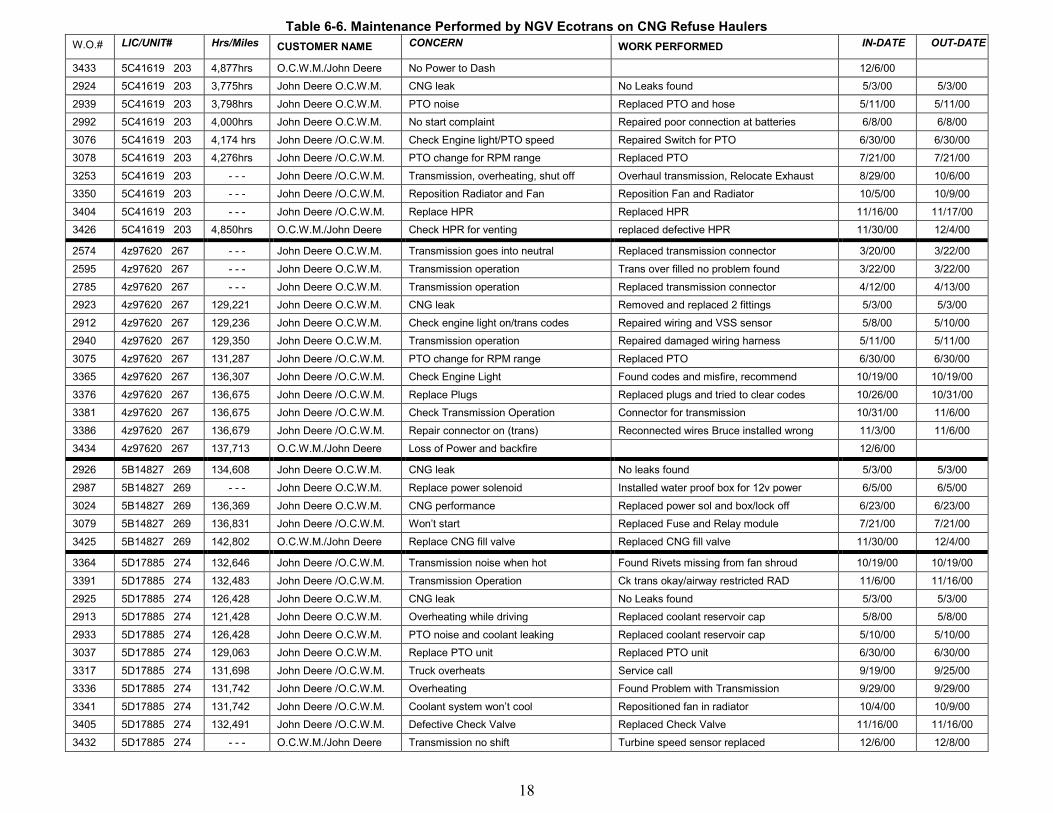
18
Table 6-6. Maintenance Performed by NGV Ecotrans on CNG Refuse HaulersW.O.# LIC/UNIT# Hrs/Miles CUSTOMER NAME CONCERN WORK PERFORMED IN-DATE OUT-DATE
3433 5C41619 203 4,877hrs O.C.W.M./John Deere No Power to Dash 12/6/002924 5C41619 203 3,775hrs John Deere O.C.W.M. CNG leak No Leaks found 5/3/00 5/3/002939 5C41619 203 3,798hrs John Deere O.C.W.M. PTO noise Replaced PTO and hose 5/11/00 5/11/002992 5C41619 203 4,000hrs John Deere O.C.W.M. No start complaint Repaired poor connection at batteries 6/8/00 6/8/003076 5C41619 203 4,174 hrs John Deere /O.C.W.M. Check Engine light/PTO speed Repaired Switch for PTO 6/30/00 6/30/003078 5C41619 203 4,276hrs John Deere /O.C.W.M. PTO change for RPM range Replaced PTO 7/21/00 7/21/003253 5C41619 203 - - - John Deere /O.C.W.M. Transmission, overheating, shut off Overhaul transmission, Relocate Exhaust 8/29/00 10/6/003350 5C41619 203 - - - John Deere /O.C.W.M. Reposition Radiator and Fan Reposition Fan and Radiator 10/5/00 10/9/003404 5C41619 203 - - - John Deere /O.C.W.M. Replace HPR Replaced HPR 11/16/00 11/17/003426 5C41619 203 4,850hrs O.C.W.M./John Deere Check HPR for venting replaced defective HPR 11/30/00 12/4/00
2574 4z97620 267 - - - John Deere O.C.W.M. Transmission goes into neutral Replaced transmission connector 3/20/00 3/22/002595 4z97620 267 - - - John Deere O.C.W.M. Transmission operation Trans over filled no problem found 3/22/00 3/22/002785 4z97620 267 - - - John Deere O.C.W.M. Transmission operation Replaced transmission connector 4/12/00 4/13/002923 4z97620 267 129,221 John Deere O.C.W.M. CNG leak Removed and replaced 2 fittings 5/3/00 5/3/002912 4z97620 267 129,236 John Deere O.C.W.M. Check engine light on/trans codes Repaired wiring and VSS sensor 5/8/00 5/10/002940 4z97620 267 129,350 John Deere O.C.W.M. Transmission operation Repaired damaged wiring harness 5/11/00 5/11/003075 4z97620 267 131,287 John Deere /O.C.W.M. PTO change for RPM range Replaced PTO 6/30/00 6/30/003365 4z97620 267 136,307 John Deere /O.C.W.M. Check Engine Light Found codes and misfire, recommend 10/19/00 10/19/003376 4z97620 267 136,675 John Deere /O.C.W.M. Replace Plugs Replaced plugs and tried to clear codes 10/26/00 10/31/003381 4z97620 267 136,675 John Deere /O.C.W.M. Check Transmission Operation Connector for transmission 10/31/00 11/6/003386 4z97620 267 136,679 John Deere /O.C.W.M. Repair connector on (trans) Reconnected wires Bruce installed wrong 11/3/00 11/6/003434 4z97620 267 137,713 O.C.W.M./John Deere Loss of Power and backfire 12/6/00
2926 5B14827 269 134,608 John Deere O.C.W.M. CNG leak No leaks found 5/3/00 5/3/002987 5B14827 269 - - - John Deere O.C.W.M. Replace power solenoid Installed water proof box for 12v power 6/5/00 6/5/003024 5B14827 269 136,369 John Deere O.C.W.M. CNG performance Replaced power sol and box/lock off 6/23/00 6/23/003079 5B14827 269 136,831 John Deere /O.C.W.M. Won’t start Replaced Fuse and Relay module 7/21/00 7/21/003425 5B14827 269 142,802 O.C.W.M./John Deere Replace CNG fill valve Replaced CNG fill valve 11/30/00 12/4/00
3364 5D17885 274 132,646 John Deere /O.C.W.M. Transmission noise when hot Found Rivets missing from fan shroud 10/19/00 10/19/003391 5D17885 274 132,483 John Deere /O.C.W.M. Transmission Operation Ck trans okay/airway restricted RAD 11/6/00 11/16/002925 5D17885 274 126,428 John Deere O.C.W.M. CNG leak No Leaks found 5/3/00 5/3/002913 5D17885 274 121,428 John Deere O.C.W.M. Overheating while driving Replaced coolant reservoir cap 5/8/00 5/8/002933 5D17885 274 126,428 John Deere O.C.W.M. PTO noise and coolant leaking Replaced coolant reservoir cap 5/10/00 5/10/003037 5D17885 274 129,063 John Deere O.C.W.M. Replace PTO unit Replaced PTO unit 6/30/00 6/30/003317 5D17885 274 131,698 John Deere /O.C.W.M. Truck overheats Service call 9/19/00 9/25/003336 5D17885 274 131,742 John Deere /O.C.W.M. Overheating Found Problem with Transmission 9/29/00 9/29/003341 5D17885 274 131,742 John Deere /O.C.W.M. Coolant system won’t cool Repositioned fan in radiator 10/4/00 10/9/003405 5D17885 274 132,491 John Deere /O.C.W.M. Defective Check Valve Replaced Check Valve 11/16/00 11/16/003432 5D17885 274 - - - O.C.W.M./John Deere Transmission no shift Turbine speed sensor replaced 12/6/00 12/8/00
19
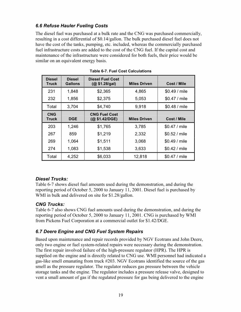
6.6 Refuse Hauler Fueling CostsThe diesel fuel was purchased at a bulk rate and the CNG was purchased commercially,resulting in a cost differential of $0.14/gallon. The bulk purchased diesel fuel does nothave the cost of the tanks, pumping, etc. included, whereas the commercially purchasedfuel infrastructure costs are added to the cost of the CNG fuel. If the capital cost andmaintenance of the infrastructure were considered for both fuels, their price would besimilar on an equivalent energy basis.
Table 6-7. Fuel Cost Calculations
Diesel Trucks:Table 6-7 shows diesel fuel amounts used during the demonstration, and during thereporting period of October 5, 2000 to January 11, 2001. Diesel fuel is purchased byWMI in bulk and delivered on site for $1.28/gallon.
CNG Trucks:Table 6-7 also shows CNG fuel amounts used during the demonstration, and during thereporting period of October 5, 2000 to January 11, 2001. CNG is purchased by WMIfrom Pickens Fuel Corporation at a commercial outlet for $1.42/DGE.
6.7 Deere Engine and CNG Fuel System RepairsBased upon maintenance and repair records provided by NGV Ecotrans and John Deere,only two engine or fuel system-related repairs were necessary during the demonstration.The first repair involved failure of the high-pressure regulator (HPR). The HPR issupplied on the engine and is directly related to CNG use. WMI personnel had indicated agas-like smell emanating from truck #203. NGV Ecotrans identified the source of the gassmell as the pressure regulator. The regulator reduces gas pressure between the vehiclestorage tanks and the engine. The regulator includes a pressure release valve, designed tovent a small amount of gas if the regulated pressure for gas being delivered to the engine
DieselTruck
DieselGallons
Diesel Fuel Cost(@ $1.28/gal) Miles Driven Cost / Mile
231 1,848 $2,365 4,865 $0.49 / mile232 1,856 $2,375 5,053 $0.47 / mile
Total 3,704 $4,740 9,918 $0.48 / mile
CNGTruck DGE
CNG Fuel Cost(@ $1.42/DGE) Miles Driven Cost / Mile
203 1,246 $1,765 3,785 $0.47 / mile267 859 $1,219 2,332 $0.52 / mile269 1,064 $1,511 3,068 $0.49 / mile274 1,083 $1,538 3,633 $0.42 / mile
Total 4,252 $6,033 12,818 $0.47 / mile

20
becomes excessive. This maintains the correct operating pressure required by the engine,but produces the gas smell noticed by WMI personnel. The problem with the regulatorwas traced to contamination in the relief valve seat, which resulted in gas seepage.
Unrelated to this problem, a higher performance gas regulator was already planned forinstallation on the WMI trucks. Therefore, Ecotrans replaced the pressure regulator withthe new boost-biased pressure regulator. Ecotrans installed a tap in the air intake(downstream of the turbo) that connected to the regulator. One advantage of the new styleregulator is that as boost pressure builds with additional power requirements, theregulator increases the gas pressure to provide the necessary fuel for that load. In otherwords, under boost conditions more fuel can be supplied via the regulator.
The second problem involved what was first believed to be blown head gasket on truck#267 but was found to be improper intake air filtration. In December, Ecotrans reportedwhite smoke coming from the exhaust and an engine misfire. They also noticed smokeand oil between the cylinder head and engine block on the driver's side of the engine. Theengine was removed and sent to John Deere Engine Works to be disassembled andinspected. The inspection showed no signs of a head gasket failure. There was severeknock damage to piston #1, debris damage to the compressor of the turbocharger,abnormal wear on the top compression rings and cylinder liners, and fine particle debrisin the air intake system. Based on the inspection, it appears that the intake air was notproperly filtered. The resulting debris caused damage to the compressor wheel of theturbocharger and caused the cylinder liners and top compression rings to wearabnormally. The excessive wear of rings and liners caused high oil consumption, whichled to a knock condition. The engine controller in this vehicle did not have the knocksensing capabilities of the production controller, so it was not able to retard the sparktiming or set an engine fault code. There was also no record indicating drivers takingcorrective action for knocking conditions. This allowed knocking to occur, causingsevere damage to piston #1 and a significant decrease in cylinder pressure, misfire, andwhite smoke as reported by Ecotrans. Improper intake air filtration would have causedthe same result with a diesel engine, therefore it was not charged as a CNG specificfailure in this report. The cause of this failure was improper maintenance and was notCNG related.
The oil and smoke coming from the driver's side of the engine was most likely due to afailed exhaust manifold gasket combined with high oil consumption and misfire. Asimilar exhaust manifold gasket failure occurred on the life test engine. This gasketproblem has been corrected by changing the fastener material.
6.8 Driveability and PerformanceOne key factor in assessing the commercial viability for CNG-fueled refuse haulers is howdrivers perceive their performance compared to the diesel vehicle they normally operate.Driver input is also important because drivers are usually the first to detect a problem in thesystem. The general practice by WMI is to assign multiple drivers to its various diesel-fueled refuse haulers. For the CNG refuse hauler demonstration, a different system was setup. In the interest of minimizing variability and maximizing safety and data collection
21
effectiveness, WMI assigned a select few drivers to operate the CNG refuse haulers. Forthe most part, one particular driver exclusively operated a particular CNG refuse hauler.
The WMI drivers were satisfied with the driveability and performance of the CNG trucks.One change they requested was for the compactor speed to be matched to that of theconventional, diesel-fueled haulers.

22
7.0. Development of Prototype Engines in Service (Task #5)Once the on-highway testing was underway, John Deere worked with the trucking fleet toovercome any performance, reliability, or durability problems that were experienced. SwRIwas sub-contracted to assist John Deere with any engine calibration work needed to resolvefield problems.
To address the problem related to slower than desired acceleration for the first 1-2 secondsand improve torque at lower engine speeds, a new Garrett turbocharger was selected. Aprototype of this new turbocharger configuration was first run on a lab engine at SwRI toverify design expectations. This change improved the low-end torque of the engine. At thesame time, by increasing the airflow at low speeds, the calibration could be modified tooperate the engine at leaner air/fuel ratios. The result was an engine with slightly loweremissions due to leaner operation. In the vehicle, the new turbocharger greatly reduced thelag but did not totally eliminate it during acceleration from a complete stop.
To see how the performance was affected in the truck, new control calibrations wereinstalled on the truck engines. These calibrations modified the shape of the full load torquecurve on the engine at lower operating speeds. In particular, the torque curve was changedto increase the torque levels at speeds below peak torque. The actual torque increase variedwith engine speed, but at engine speeds below 1600 rpm the torque increased from 2%to16%.
WMI had requested that the hydraulic pump speed for the compactor be matched to that ofthe conventional, diesel-fueled haulers. Improved operation of the trucks was obtained byraising the engine’s optional idle speed from 1100 rpm to 1300 rpm. The engine controllersoftware was reprogrammed for that revision. This change increased the hydraulic pumpspeed to a more acceptable level, but not quite to the expectations of the operators based onprevious experience.

23
8.0. Commercial Engine Configuration and FTP Test (Task #6)One objective of the demonstration program was to have a production engine certified tothe 2.5 g/bhp-hr Optional Low NOx emissions standard for CARB. During initial enginedevelopment results were close enough to a lower target that further research was justifiedto actually reach the lower target. The following paragraphs describe the process involvedand the final certification to the 2.0 g/bhp-hr Optional Low NOx emissions standard.
The development emissions targets as well as the CARB Low NOx standards are shown inTable 8-1. These development targets were calculated based on the standards requirements,deterioration factors, and a margin for engine build variability.
Table 8-1. Emissions Targets for Development (units in g/bhp-hr)Pollutant Abbreviation Development
TargetCARB Low NOx
StandardNitrogen oxides NOx 1.840 2.5
Nonmethane hydrocarbons NMHC 1.080 1.2Carbon monoxide CO 2.800 15.5Particulate matter PM 0.045 0.05
8.1 Test PreparationsThe transient emissions tests were conducted according to the EPA Federal TestProcedure (FTP), as specified in the Code of Federal Regulations (CFR), Title 40, Part86, Subpart N. For all tests, the curb idle transmission torque (CITT) was set to 70 lb-ft.The test fuel used for emissions testing was blended to meet the CARB specifications fora certification fuel blend. The composition of the blended fuel, as measured by gaschromatographic analysis, is shown in Table 8-2.
Table 8-2. Fuel Used for Emissions TestingComponent Concentration
(%)C1 (Methane) 90.69C2 (Ethane + Ethylene) 3.74C3+ (Propane) 1.96Inerts (Nitrogen) 3.61
The engine was equipped with a Woodward Governor Company gas engine managementsystem. The latest revision of the John Deere 280 hp software from Woodward GovernorCompany was downloaded into flash memory of the controller. This software was usedwithout modification for all the test runs for emissions certification purposes. The enginewas also equipped with an oxidation catalyst, except where noted.

24
8.2 Performance Results:Power validation runs were conducted to verify that the engine was operating correctlyand to ensure that all the test cell conditions, such as inlet and exhaust restrictions, etc.were correct. A summary of parameters measured during the power validation is listed inTable 8-3.
Table 8-3. Performance Results from Power ValidationParameter Rated Power Peak TorqueSpeed rpm 2200 1600Torque lb-ft 681 929Power bhp 285 283Fuel Flow lb/hr 94.1 89.3Intake Restriction in. H2O -8.00 -7.10Exhaust Restriction in. Hg 2.00 1.83Intake Air Temperature °F 72 69Intake Air Dew Point °F 61.9 61.2∆P across Intercooler in. H2O 27.20 12.24
A torque map was generated by operating the engine at wide-open throttle from 600 rpmto 2400 rpm. A plot of the full load torque curve for the test engine is shown below inFigure 8-1.
0
100
200
300
400
500
600
700
800
900
1000
600 900 1200 1500 1800 2100 2400
Engine Speed (rpm)
Torque CurveJohn Deere 280 hp 8.1L CNG Engine
S/N 6081H096224
Figure 8-1. Torque Curve for 280 Hp John Deere 8.1L Natural Gas Engine
Following completion of the torque map, several practice cycles were conducted to tune thetest cell controller so that the engine would pass cycle statistics reliably and to verify thatthe engine was operating correctly.
25
8.2.1 Emissions Results With Catalytic Aftertreatment
Transient emissions testing of the 280 hp certification test engine was completed at SwRIafter the development work was complete. Calibration work was conducted to achieve thetarget NOx level of 1.84 g/bhp-hr out of the engine in order to have compliance with the 2.5emissions standard. The engine was equipped with an oxidation catalyst and operated on aCARB CNG certification fuel blend. A cold start/hot start test sequence was conducted.The engine’s actual performance enabled Deere to certify to 2.0 g NOx rather that theoriginal target of 2.5 g NOx.
The composite test results for this configuration are shown in Figure 8-2. Results for NOx,CO, nonmethane hydrocarbons (NMHC), and particulate matter (PM) are shown. Thecomposite test results are a weighted average, with the cold start weighting factor equal to1/7 and the hot-start weighting factor equal to 6/7. Note that the bars in the graph are scaledfor graphical clarity, i.e., the CO emissions bar is divided by a factor of 10 and theparticulate emissions bar is multiplied by a factor of 10. For comparison purposes, a datatable is included in Figure 8-2 that shows some reference emissions values in addition tothe actual measured value; the numbers in the data table are not scaled.
The first reference value is the emissions limit as dictated by the appropriate CARBoptional 2.5 Low NOx standard development target. The second reference value is the limitlevel adjusted to reflect the effect of the 2900 hour useful life deterioration factor (DF). Thethird reference value is the calibration target for certification. This number is a percentageof the DF-adjusted value and provides a margin to account for engine variability. As can beseen in Figure 8-2, the actual engine emissions easily meet the development target levelsand are significantly lower than the 2.5 Low NOx standard. As expected, NOx had theclosest margin. For the other emissions (CO, PM, and NMHC), the actual levels weresignificantly lower than the target values.

26
Emissions Test Results ComparisonJohn Deere 280 hp 8.1L CNG Engine
S/N 6081H096224Oxidation Catalyst Used
0.00
0.50
1.00
1.50
2.00
2.50
3.00
Emissions(g/bhp-hr)
Standard 2.50 15.5 0.050 1.20DF-Adj. 2.05 3.1 0.050 1.20Target 1.84 2.8 0.045 1.08Actual 1.51 0.2 0.014 0.25
NOx CO / 10 PM x 10 NMHC
Figure 8-2. Composite Emissions Results for Engine Equippedwith an Oxidation Catalyst
8.2.2 Emissions Results Without Catalytic Aftertreatment
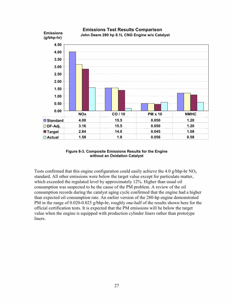
Following the successful completion of these tests, the catalyst was removed from theengine for additional testing with no aftertreatment. The same calibration developed for thecatalyst-equipped engine was used, since it was anticipated that the calibration developedfor this application also allowed the engine to meet the EPA 4.0 g/bhp-hr NOx on-highwaytruck standard. The exhaust restriction was adjusted at rated conditions to provideequivalent backpressure to that obtained with the catalyst. A cold start/hot start testsequence was subsequently conducted. Composite test results for these tests were plottedrelative to the EPA Heavy Duty Diesel Engine standards for trucks and urban buses and areshown in Figure 8-3.
27
Emissions Test Results ComparisonJohn Deere 280 hp 8.1L CNG Engine w/o Catalyst
0.00
0.50
1.00
1.50
2.00
2.50
3.00
3.50
4.00
4.50
Emissions(g/bhp-hr)
Standard 4.00 15.5 0.050 1.20DF-Adj. 3.16 15.5 0.050 1.20Target 2.84 14.0 0.045 1.08Actual 1.58 1.8 0.056 0.58
NOx CO / 10 PM x 10 NMHC
Figure 8-3. Composite Emissions Results for the Enginewithout an Oxidation Catalyst
Tests confirmed that this engine configuration could easily achieve the 4.0 g/bhp-hr NOxstandard. All other emissions were below the target value except for particulate matter,which exceeded the regulated level by approximately 12%. Higher than usual oilconsumption was suspected to be the cause of the PM problem. A review of the oilconsumption records during the catalyst aging cycle confirmed that the engine had a higherthan expected oil consumption rate. An earlier version of the 280-hp engine demonstratedPM in the range of 0.020-0.025 g/bhp-hr, roughly one-half of the results shown here for theofficial certification tests. It is expected that the PM emissions will be below the targetvalue when the engine is equipped with production cylinder liners rather than prototypeliners.
28
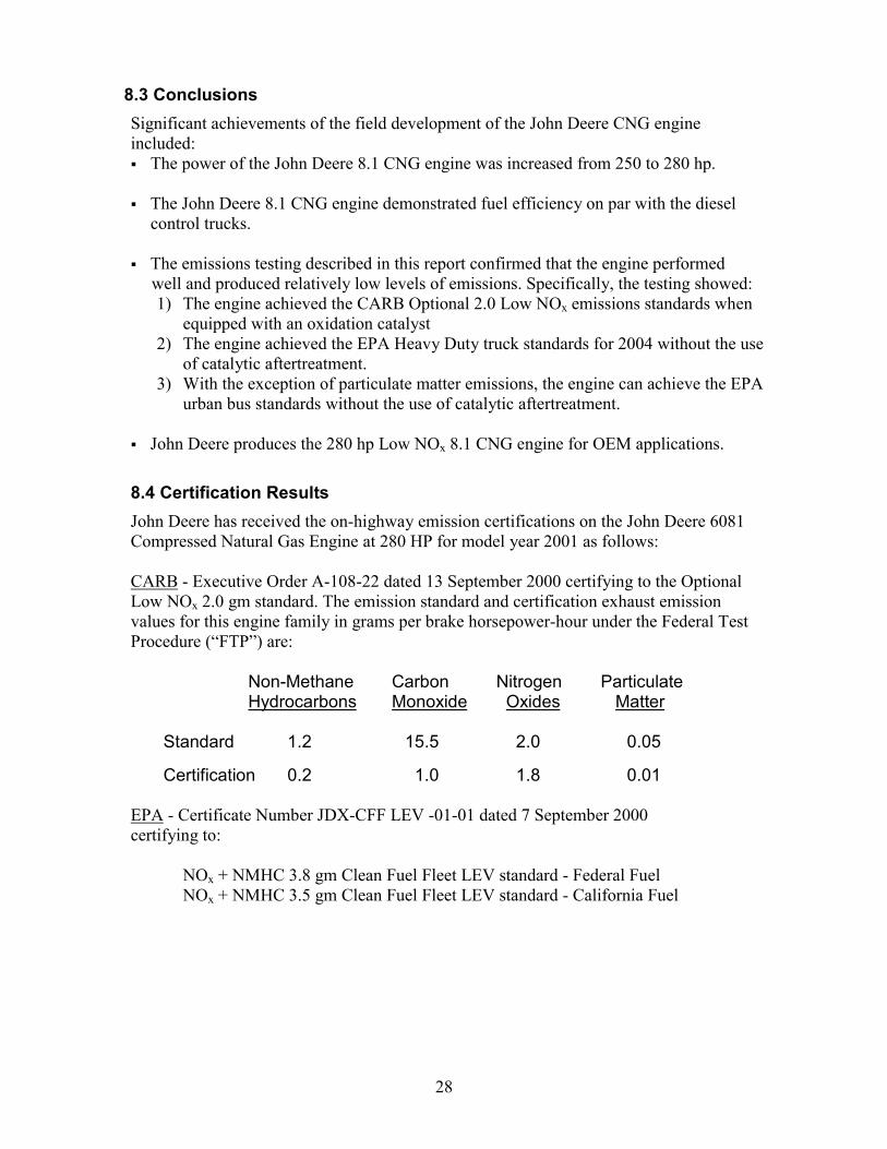
8.3 ConclusionsSignificant achievements of the field development of the John Deere CNG engineincluded:� The power of the John Deere 8.1 CNG engine was increased from 250 to 280 hp.
� The John Deere 8.1 CNG engine demonstrated fuel efficiency on par with the dieselcontrol trucks.
� The emissions testing described in this report confirmed that the engine performedwell and produced relatively low levels of emissions. Specifically, the testing showed:1) The engine achieved the CARB Optional 2.0 Low NOx emissions standards when
equipped with an oxidation catalyst2) The engine achieved the EPA Heavy Duty truck standards for 2004 without the use
of catalytic aftertreatment.3) With the exception of particulate matter emissions, the engine can achieve the EPA
urban bus standards without the use of catalytic aftertreatment.
� John Deere produces the 280 hp Low NOx 8.1 CNG engine for OEM applications.
8.4 Certification ResultsJohn Deere has received the on-highway emission certifications on the John Deere 6081Compressed Natural Gas Engine at 280 HP for model year 2001 as follows:
CARB - Executive Order A-108-22 dated 13 September 2000 certifying to the OptionalLow NOx 2.0 gm standard. The emission standard and certification exhaust emissionvalues for this engine family in grams per brake horsepower-hour under the Federal TestProcedure (“FTP”) are:
Non-Methane Carbon Nitrogen ParticulateHydrocarbons Monoxide Oxides Matter
Standard 1.2 15.5 2.0 0.05
Certification 0.2 1.0 1.8 0.01
EPA - Certificate Number JDX-CFF LEV -01-01 dated 7 September 2000certifying to:
NOx + NMHC 3.8 gm Clean Fuel Fleet LEV standard - Federal FuelNOx + NMHC 3.5 gm Clean Fuel Fleet LEV standard - California Fuel
29
9.0. Environmental, Safety, and Health Compliance (Task #7)All work performed on this project has been conducted in ways that conform withapplicable federal, state, and local environmental, safety, and health codes andregulations.
Truck #274 had a fire in trash compaction unit on morning of August 3, 2000. The truckwas parked over night in the WMI lot with a full load of compacted trash. The fire isbelieved to have started in the trash due to spontaneous combustion. The fire was put outquickly and damage was limited to the body of the compaction unit. The paint on thecargo body was badly damaged and truck was out of service for stripping & re-painting.There was no damage to the engine, fuel systems, controls, or CNG fuel tanks.
10.0. Future PlansJohn Deere has released the newly certified engine for full commercial production,making it available for OEM on-highway applications. In addition, the successdemonstrated and the knowledge gained during this program has demonstrated thefeasibility of proceeding with future programs to pursue further reductions in natural gasengine emission levels.
Improvement of the oil consumption rate will be required to reduce the particulate matteremissions below 0.050 g/bhp-hr. Similar John Deere CNG engines produce significantlylower levels of PM, so a detailed study of the differences in oil control hardware betweenthe production engine, the earlier development 280 hp engine, and the current production280 hp will be made. Additional emissions testing of an engine with improved oil controlsystems are planned in the near future. This will allow certification of the engine to thelowest possible PM standards.

30
Attachment # 1
31
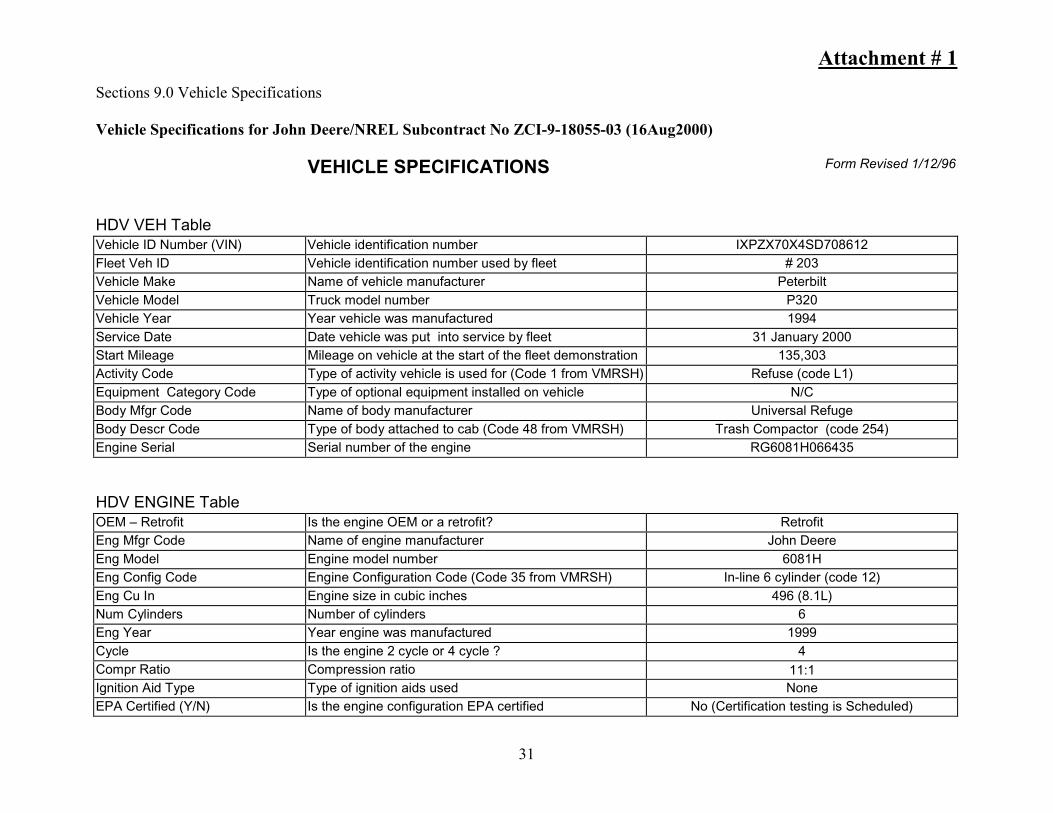
Sections 9.0 Vehicle Specifications
Vehicle Specifications for John Deere/NREL Subcontract No ZCI-9-18055-03 (16Aug2000)
VEHICLE SPECIFICATIONS Form Revised 1/12/96
HDV VEH TableVehicle ID Number (VIN) Vehicle identification number IXPZX70X4SD708612Fleet Veh ID Vehicle identification number used by fleet # 203Vehicle Make Name of vehicle manufacturer PeterbiltVehicle Model Truck model number P320Vehicle Year Year vehicle was manufactured 1994Service Date Date vehicle was put into service by fleet 31 January 2000Start Mileage Mileage on vehicle at the start of the fleet demonstration 135,303Activity Code Type of activity vehicle is used for (Code 1 from VMRSH) Refuse (code L1)Equipment Category Code Type of optional equipment installed on vehicle N/CBody Mfgr Code Name of body manufacturer Universal RefugeBody Descr Code Type of body attached to cab (Code 48 from VMRSH) Trash Compactor (code 254)Engine Serial Serial number of the engine RG6081H066435
HDV ENGINE TableOEM – Retrofit Is the engine OEM or a retrofit? RetrofitEng Mfgr Code Name of engine manufacturer John DeereEng Model Engine model number 6081HEng Config Code Engine Configuration Code (Code 35 from VMRSH) In-line 6 cylinder (code 12)Eng Cu In Engine size in cubic inches 496 (8.1L)Num Cylinders Number of cylinders 6Eng Year Year engine was manufactured 1999Cycle Is the engine 2 cycle or 4 cycle ? 4Compr Ratio Compression ratio 11:1Ignition Aid Type Type of ignition aids used NoneEPA Certified (Y/N) Is the engine configuration EPA certified No (Certification testing is Scheduled)

32
Maximum bHp Rated maximum brake horsepower of engine 280Rpm of Max bHp Rpm at rated maximum brake horsepower 2200Maximum Torque (ft-lbs) Rated maximum torque of engine 900 lb-ftRpm of Max Torque Rpm at rated maximum torque 1600Oil Capacity (qts) Oil capacity in quarts 24Blower? (Y/N) Does the engine have a blower? NoTurbocharger? (Y/N) Does the engine have a turbocharger? Yes
HDV FUEL SYSTEMS TableFuel Type Code What type of fuel is engine designed for? CNGDiesel Additives Type of additives used in diesel fuel NAAlt Fuel Additives Type of additives used in alternative fuel NoneMech Elec For liquid fuel engines, are the injectors mechanically or
electronically controlled?NA
Injector Mfr Name of liquid fuel injector manufacturer NAInj Model Liquid fuel injector model number NANum of Injectors Number of liquid fuel injectors NALiq-Fuel Filter Mfr Name of liquid fuel filter manufacturer NALiq-Fuel Filter Model Liquid fuel filter model number NAFuel Induction For gaseous fuel engines, is it injection or fumigation? InjectionAir Intake Throttle (Y/N) Does the engine use an air intake throttle YesGas Equip (OEM/Retrofit) Is the gas fuel system OEM or retrofit? Engine OEM, vehicle tanks RetrofitNumber of Alt Fuel Tanks Number of alternative fuel tanks 4Number of Diesel Tanks Number of diesel tanks NAAF Max Work Press (psi) Alternative fuel maximum working pressure in psi 3500Amount of Useable AF Total useful alternative fuel in tank(s) 7,148 SCF @ 3600 psiAlt Fuel Units Units used for alternative fuel tank(s) useful volume SCF + standard cubic feetAmount of Useable Diesel Total useful diesel fuel in tank(s) NADiesel Fuel Units Units used for diesel fuel tank(s) useful volume NAAF Tank Manufacturer Name of alternative fuel tank(s) manufacturer Lincoln (2) 18.4” x 78”, SCI (2) 12” X 60”Diesel Tank Manufacturer Name of diesel fuel tank(s) manufacturer NAAlt Fuel Tank Model Alternative fuel tank(s) model number Lincoln (R240057-113), SCI (CS12.06036)Diesel Tank Model Diesel fuel tank(s) model number NA
33
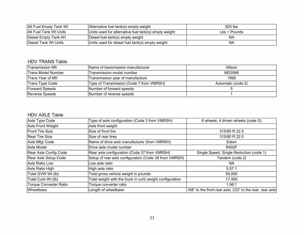
Alt Fuel Empty Tank Wt Alternative fuel tank(s) empty weight 820 lbsAlt Fuel Tank Wt Units Units used for alternative fuel tank(s) empty weight Lbs = PoundsDiesel Empty Tank Wt Diesel fuel tank(s) empty weight NADiesel Tank Wt Units Units used for diesel fuel tank(s) empty weight NA
HDV TRANS TableTransmission Mfr Name of transmission manufacturer AllisonTrans Model Number Transmission model number MD3066Trans Year of Mfr Transmission year of manufacture 1999Trans Type Code Type of Transmission (Code 7 from VMRSH) Automatic (code 2)Forward Speeds Number of forward speeds 5Reverse Speeds Number of reverse speeds 1
HDV AXLE TableAxle Type Code Type of axle configuration (Code 3 from VMRSH) 8 wheels, 4 driven wheels (code G)Axle Front Weight Axle front weightFront Tire Size Size of front tire 315/80 R 22.5Rear Tire Size Size of rear tires 315/80 R 22.5Axle Mfgr Code Name of drive axle manufacturer (from VMRSH) EatonAxle Model Drive axle model number R402FRear Axle Config Code Rear axle configuration (Code 37 from VMRSH) Single Speed, Single Reduction (code 1)Rear Axle Setup Code Setup of rear axle configuration (Code 38 from VMRSH) Tandem (code 2)Axle Ratio Low Low axle ratio NAAxle Ratio High High axle ratio 5.57:1Total GVW Wt (lb) Total gross vehicle weight in pounds 50,000Total Curb Wt (lb) Total weight with the truck in curb weight configuration 17,460Torque Converter Ratio Torque converter ratio 1.98:1Wheelbase Length of wheelbase 168” to the front rear axle, 233” to the rear, rear axle

34
HDV EMISSION TableCat Conv Does the vehicle have a catalytic converter? Y or N NoCat Conv Mfg Name of catalytic converter manufacturer. NACat Conv Model Model number of the catalytic converter. NADsl Prt Trap Does the vehicle have a diesel particulate trap? Y or N NATrap Mfg Name of the particulate trap manufacturer. NATrap Model Model number of the particulate trap. NATrap Regen_Type Type of trap regeneration process NATrap Conf Particulate trap configuration NANum Trap Ele Number of particulate trap elements NATrap Sys Wt Weight of the particulate trap system NA

Attachment # 2
35
Sections 9.0 Vehicle Specifications
Vehicle Specifications for John Deere/NREL Subcontract No ZCI-9-18055-03 (16Aug2000)
VEHICLE SPECIFICATIONS Form Revised 1/12/96
HDV VEH TableVehicle ID Number (VIN) Vehicle identification number IXPZL79XXRD706467Fleet Veh ID Vehicle identification number used by fleet # 267Vehicle Make Name of vehicle manufacturer PeterbiltVehicle Model Truck model number P320Vehicle Year Year vehicle was manufactured 1994Service Date Date vehicle was put into service by fleet 19 February 2000Start Mileage Mileage on vehicle at the start of the fleet demonstration 127,857Activity Code Type of activity vehicle is used for (Code 1 from VMRSH) Refuse (code L1)Equipment Category Code Type of optional equipment installed on vehicle N/CBody Mfgr Code Name of body manufacturer Universal RefugeBody Descr Code Type of body attached to cab (Code 48 from VMRSH) Trash Compactor (code 254)Engine Serial Serial number of the engine RG6081H096215
HDV ENGINE TableOEM – Retrofit Is the engine OEM or a retrofit? RetrofitEng Mfgr Code Name of engine manufacturer John DeereEng Model Engine model number 6081HEng Config Code Engine Configuration Code (Code 35 from VMRSH) In-line 6 cylinder (code 12)Eng Cu In Engine size in cubic inches 496 (8.1L)Num Cylinders Number of cylinders 6Eng Year Year engine was manufactured 1999Cycle Is the engine 2 cycle or 4 cycle ? 4Compr Ratio Compression ratio 11:1Ignition Aid Type Type of ignition aids used None

36
EPA Certified (Y/N) Is the engine configuration EPA certified No (Certification testing is Scheduled)Maximum bHp Rated maximum brake horsepower of engine 280Rpm of Max bHp Rpm at rated maximum brake horsepower 2200Maximum Torque (ft-lbs) Rated maximum torque of engine 900 lb-ftRpm of Max Torque Rpm at rated maximum torque 1600Oil Capacity (qts) Oil capacity in quarts 24Blower? (Y/N) Does the engine have a blower? NoTurbocharger? (Y/N) Does the engine have a turbocharger? Yes
HDV FUEL SYSTEMS TableFuel Type Code What type of fuel is engine designed for? CNGDiesel Additives Type of additives used in diesel fuel NAAlt Fuel Additives Type of additives used in alternative fuel NoneMech Elec For liquid fuel engines, are the injectors mechanically or
electronically controlled?NA
Injector Mfr Name of liquid fuel injector manufacturer NAInj Model Liquid fuel injector model number NANum of Injectors Number of liquid fuel injectors NALiq-Fuel Filter Mfr Name of liquid fuel filter manufacturer NALiq-Fuel Filter Model Liquid fuel filter model number NAFuel Induction For gaseous fuel engines, is it injection or fumigation? InjectionAir Intake Throttle (Y/N) Does the engine use an air intake throttle YesGas Equip (OEM/Retrofit) Is the gas fuel system OEM or retrofit? Engine OEM, vehicle tanks RetrofitNumber of Alt Fuel Tanks Number of alternative fuel tanks 4Number of Diesel Tanks Number of diesel tanks NAAF Max Work Press (psi) Alternative fuel maximum working pressure in psi 3500Amount of Useable AF Total useful alternative fuel in tank(s) 7,148 SCF @ 3600 psiAlt Fuel Units Units used for alternative fuel tank(s) useful volume SCF + standard cubic feetAmount of Useable Diesel Total useful diesel fuel in tank(s) NADiesel Fuel Units Units used for diesel fuel tank(s) useful volume NAAF Tank Manufacturer Name of alternative fuel tank(s) manufacturer Lincoln (2) 18.4” x 78”, SCI (2) 12” X 60”Diesel Tank Manufacturer Name of diesel fuel tank(s) manufacturer NAAlt Fuel Tank Model Alternative fuel tank(s) model number Lincoln (R240057-113), SCI (CS12.06036)
37
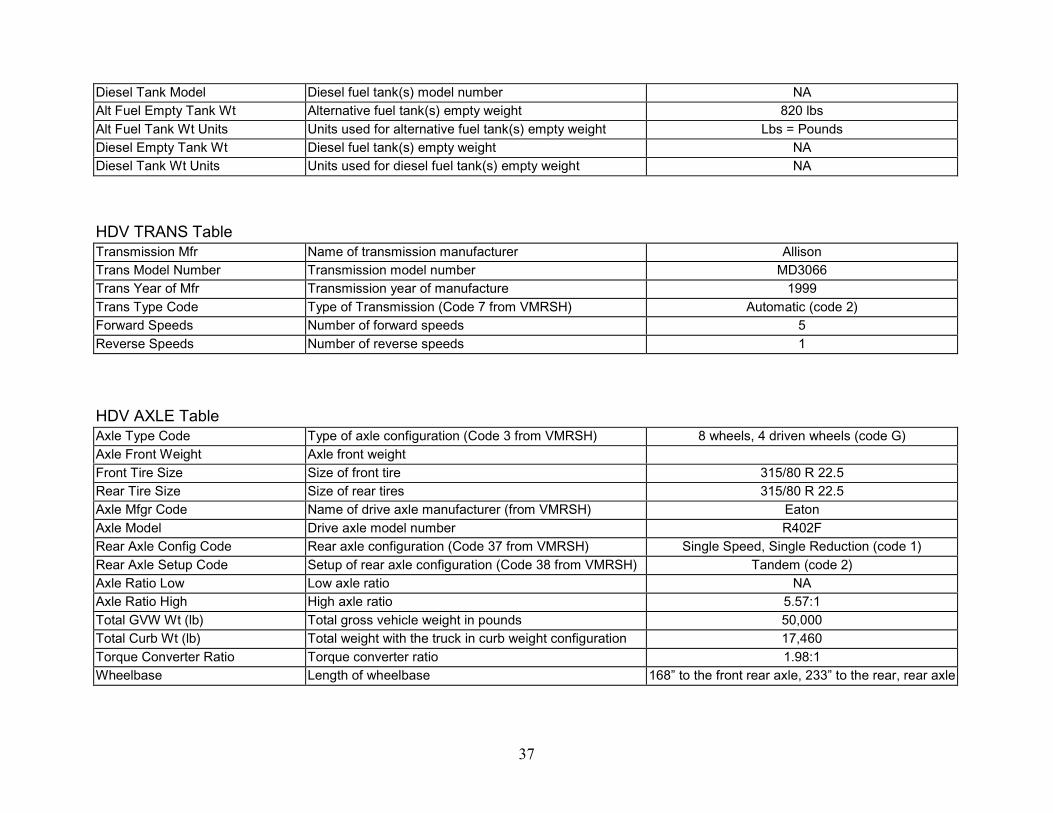
Diesel Tank Model Diesel fuel tank(s) model number NAAlt Fuel Empty Tank Wt Alternative fuel tank(s) empty weight 820 lbsAlt Fuel Tank Wt Units Units used for alternative fuel tank(s) empty weight Lbs = PoundsDiesel Empty Tank Wt Diesel fuel tank(s) empty weight NADiesel Tank Wt Units Units used for diesel fuel tank(s) empty weight NA
HDV TRANS TableTransmission Mfr Name of transmission manufacturer AllisonTrans Model Number Transmission model number MD3066Trans Year of Mfr Transmission year of manufacture 1999Trans Type Code Type of Transmission (Code 7 from VMRSH) Automatic (code 2)Forward Speeds Number of forward speeds 5Reverse Speeds Number of reverse speeds 1
HDV AXLE TableAxle Type Code Type of axle configuration (Code 3 from VMRSH) 8 wheels, 4 driven wheels (code G)Axle Front Weight Axle front weightFront Tire Size Size of front tire 315/80 R 22.5Rear Tire Size Size of rear tires 315/80 R 22.5Axle Mfgr Code Name of drive axle manufacturer (from VMRSH) EatonAxle Model Drive axle model number R402FRear Axle Config Code Rear axle configuration (Code 37 from VMRSH) Single Speed, Single Reduction (code 1)Rear Axle Setup Code Setup of rear axle configuration (Code 38 from VMRSH) Tandem (code 2)Axle Ratio Low Low axle ratio NAAxle Ratio High High axle ratio 5.57:1Total GVW Wt (lb) Total gross vehicle weight in pounds 50,000Total Curb Wt (lb) Total weight with the truck in curb weight configuration 17,460Torque Converter Ratio Torque converter ratio 1.98:1Wheelbase Length of wheelbase 168” to the front rear axle, 233” to the rear, rear axle

38
HDV EMISSION TableCat Conv Does the vehicle have a catalytic converter? Y or N NoCat Conv Mfg Name of catalytic converter manufacturer. NACat Conv Model Model number of the catalytic converter. NADsl Prt Trap Does the vehicle have a diesel particulate trap? Y or N NATrap Mfg Name of the particulate trap manufacturer. NATrap Model Model number of the particulate trap. NATrap Regen_Type Type of trap regeneration process NATrap Conf Particulate trap configuration NANum Trap Ele Number of particulate trap elements NATrap Sys Wt Weight of the particulate trap system NA

Attachment # 3
39
Sections 9.0 Vehicle Specifications
Vehicle Specifications for John Deere/NREL Subcontract No ZCI-9-18055-03 (16 Nov 1999)
VEHICLE SPECIFICATIONS Form Revised 1/12/96
HDV VEH TableVehicle ID Number (VIN) Vehicle identification number IXPZL79X1RD706468Fleet Veh ID Vehicle identification number used by fleet # 269Vehicle Make Name of vehicle manufacturer PeterbiltVehicle Model Truck model number P320Vehicle Year Year vehicle was manufactured 1994Service Date Date vehicle was put into service by fleet 12 October 1999Start Mileage Mileage on vehicle at the start of the fleet demonstration 127,853Activity Code Type of activity vehicle is used for (Code 1 from VMRSH) Refuse (code L1)Equipment Category Code Type of optional equipment installed on vehicle N/CBody Mfgr Code Name of body manufacturer Universal RefugeBody Descr Code Type of body attached to cab (Code 48 from VMRSH) Trash Compactor (code 254)Engine Serial Serial number of the engine RG6081H066432
HDV ENGINE TableOEM – Retrofit Is the engine OEM or a retrofit? RetrofitEng Mfgr Code Name of engine manufacturer John DeereEng Model Engine model number 6081HEng Config Code Engine Configuration Code (Code 35 from VMRSH) In-line 6 cylinder (code 12)Eng Cu In Engine size in cubic inches 496 (8.1L)Num Cylinders Number of cylinders 6Eng Year Year engine was manufactured 1999Cycle Is the engine 2 cycle or 4 cycle ? 4Compr Ratio Compression ratio 11:1Ignition Aid Type Type of ignition aids used NoneEPA Certified (Y/N) Is the engine configuration EPA certified No (Certification testing is Scheduled)

40
Maximum bHp Rated maximum brake horsepower of engine 280Rpm of Max bHp Rpm at rated maximum brake horsepower 2200Maximum Torque (ft-lbs) Rated maximum torque of engine 900 lb-ftRpm of Max Torque Rpm at rated maximum torque 1600Oil Capacity (qts) Oil capacity in quarts 24Blower? (Y/N) Does the engine have a blower? NoTurbocharger? (Y/N) Does the engine have a turbocharger? Yes
HDV FUEL SYSTEMS TableFuel Type Code What type of fuel is engine designed for? CNGDiesel Additives Type of additives used in diesel fuel NAAlt Fuel Additives Type of additives used in alternative fuel NoneMech Elec For liquid fuel engines, are the injectors mechanically or
electronically controlled?NA
Injector Mfr Name of liquid fuel injector manufacturer NAInj Model Liquid fuel injector model number NANum of Injectors Number of liquid fuel injectors NALiq-Fuel Filter Mfr Name of liquid fuel filter manufacturer NALiq-Fuel Filter Model Liquid fuel filter model number NAFuel Induction For gaseous fuel engines, is it injection or fumigation? InjectionAir Intake Throttle (Y/N) Does the engine use an air intake throttle YesGas Equip (OEM/Retrofit) Is the gas fuel system OEM or retrofit? Engine OEM, vehicle tanks RetrofitNumber of Alt Fuel Tanks Number of alternative fuel tanks 4Number of Diesel Tanks Number of diesel tanks NAAF Max Work Press (psi) Alternative fuel maximum working pressure in psi 3500Amount of Useable AF Total useful alternative fuel in tank(s) 7,148 SCF @ 3600 psiAlt Fuel Units Units used for alternative fuel tank(s) useful volume SCF + standard cubic feetAmount of Useable Diesel Total useful diesel fuel in tank(s) NADiesel Fuel Units Units used for diesel fuel tank(s) useful volume NAAF Tank Manufacturer Name of alternative fuel tank(s) manufacturer Lincoln (2) 18.4” x 78”, SCI (2) 12” X 60”Diesel Tank Manufacturer Name of diesel fuel tank(s) manufacturer NAAlt Fuel Tank Model Alternative fuel tank(s) model number Lincoln (R240057-113), SCI (CS12.06036)Diesel Tank Model Diesel fuel tank(s) model number NA

41
Alt Fuel Empty Tank Wt Alternative fuel tank(s) empty weight 820 lbsAlt Fuel Tank Wt Units Units used for alternative fuel tank(s) empty weight Lbs = PoundsDiesel Empty Tank Wt Diesel fuel tank(s) empty weight NADiesel Tank Wt Units Units used for diesel fuel tank(s) empty weight NA
HDV TRANS TableTransmission Mfr Name of transmission manufacturer AllisonTrans Model Number Transmission model number MD3066Trans Year of Mfr Transmission year of manufacture 1999Trans Type Code Type of Transmission (Code 7 from VMRSH) Automatic (code 2)Forward Speeds Number of forward speeds 5Reverse Speeds Number of reverse speeds 1
HDV AXLE TableAxle Type Code Type of axle configuration (Code 3 from VMRSH) 8 wheels, 4 driven wheels (code G)Axle Front Weight Axle front weightFront Tire Size Size of front tire 315/80 R 22.5Rear Tire Size Size of rear tires 315/80 R 22.5Axle Mfgr Code Name of drive axle manufacturer (from VMRSH) EatonAxle Model Drive axle model number R402FRear Axle Config Code Rear axle configuration (Code 37 from VMRSH) Single Speed, Single Reduction (code 1)Rear Axle Setup Code Setup of rear axle configuration (Code 38 from VMRSH) Tandem (code 2)Axle Ratio Low Low axle ratio NAAxle Ratio High High axle ratio 5.57:1Total GVW Wt (lb) Total gross vehicle weight in pounds 50,000Total Curb Wt (lb) Total weight with the truck in curb weight configuration 17,460Torque Converter Ratio Torque converter ratio 1.98:1Wheelbase Length of wheelbase 168” to the front rear axle, 233” to the rear, rear axle
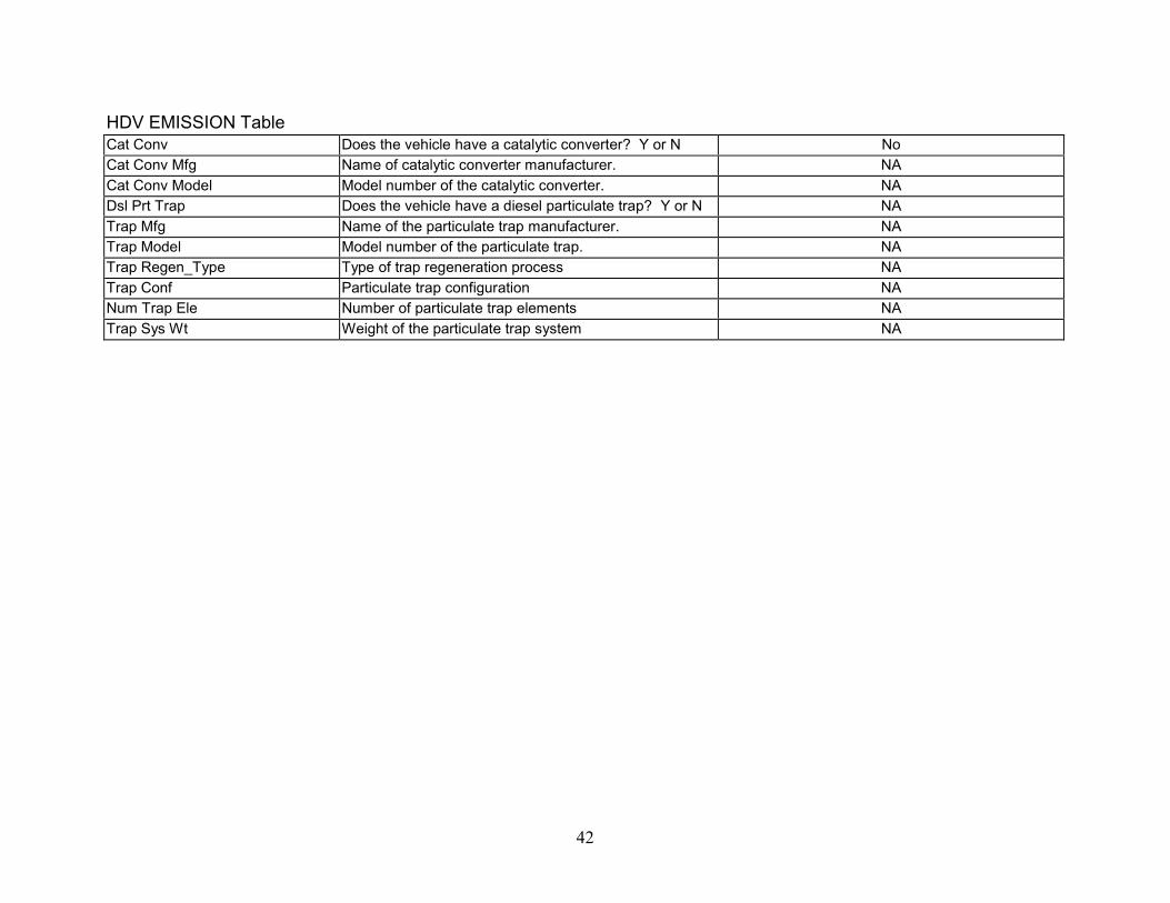
42
HDV EMISSION TableCat Conv Does the vehicle have a catalytic converter? Y or N NoCat Conv Mfg Name of catalytic converter manufacturer. NACat Conv Model Model number of the catalytic converter. NADsl Prt Trap Does the vehicle have a diesel particulate trap? Y or N NATrap Mfg Name of the particulate trap manufacturer. NATrap Model Model number of the particulate trap. NATrap Regen_Type Type of trap regeneration process NATrap Conf Particulate trap configuration NANum Trap Ele Number of particulate trap elements NATrap Sys Wt Weight of the particulate trap system NA

Attachment # 4
43
Sections 9.0 Vehicle Specifications
Vehicle Specifications for John Deere/NREL Subcontract No ZCI-9-18055-03 (16Aug2000)
VEHICLE SPECIFICATIONS Form Revised 1/12/96
HDV VEH TableVehicle ID Number (VIN) Vehicle identification number IXPZX70X0SD708610Fleet Veh ID Vehicle identification number used by fleet # 274Vehicle Make Name of vehicle manufacturer PeterbiltVehicle Model Truck model number P320Vehicle Year Year vehicle was manufactured 1994Service Date Date vehicle was put into service by fleet 22 March 2000Start Mileage Mileage on vehicle at the start of the fleet demonstration 125,670Activity Code Type of activity vehicle is used for (Code 1 from VMRSH) Refuse (code L1)Equipment Category Code Type of optional equipment installed on vehicle N/CBody Mfgr Code Name of body manufacturer Universal RefugeBody Descr Code Type of body attached to cab (Code 48 from VMRSH) Trash Compactor (code 254)Engine Serial Serial number of the engine RG6081H096216
HDV ENGINE TableOEM – Retrofit Is the engine OEM or a retrofit? RetrofitEng Mfgr Code Name of engine manufacturer John DeereEng Model Engine model number 6081HEng Config Code Engine Configuration Code (Code 35 from VMRSH) In-line 6 cylinder (code 12)Eng Cu In Engine size in cubic inches 496 (8.1L)Num Cylinders Number of cylinders 6Eng Year Year engine was manufactured 1999Cycle Is the engine 2 cycle or 4 cycle ? 4Compr Ratio Compression ratio 11:1Ignition Aid Type Type of ignition aids used NoneEPA Certified (Y/N) Is the engine configuration EPA certified No (Certification testing is Scheduled)

44
Maximum bHp Rated maximum brake horsepower of engine 280Rpm of Max bHp Rpm at rated maximum brake horsepower 2200Maximum Torque (ft-lbs) Rated maximum torque of engine 900 lb-ftRpm of Max Torque Rpm at rated maximum torque 1600Oil Capacity (qts) Oil capacity in quarts 24Blower? (Y/N) Does the engine have a blower? NoTurbocharger? (Y/N) Does the engine have a turbocharger? Yes
HDV FUEL SYSTEMS TableFuel Type Code What type of fuel is engine designed for? CNGDiesel Additives Type of additives used in diesel fuel NAAlt Fuel Additives Type of additives used in alternative fuel NoneMech Elec For liquid fuel engines, are the injectors mechanically or
electronically controlled?NA
Injector Mfr Name of liquid fuel injector manufacturer NAInj Model Liquid fuel injector model number NANum of Injectors Number of liquid fuel injectors NALiq-Fuel Filter Mfr Name of liquid fuel filter manufacturer NALiq-Fuel Filter Model Liquid fuel filter model number NAFuel Induction For gaseous fuel engines, is it injection or fumigation? InjectionAir Intake Throttle (Y/N) Does the engine use an air intake throttle YesGas Equip (OEM/Retrofit) Is the gas fuel system OEM or retrofit? Engine OEM, vehicle tanks RetrofitNumber of Alt Fuel Tanks Number of alternative fuel tanks 4Number of Diesel Tanks Number of diesel tanks NAAF Max Work Press (psi) Alternative fuel maximum working pressure in psi 3500Amount of Useable AF Total useful alternative fuel in tank(s) 7,148 SCF @ 3600 psiAlt Fuel Units Units used for alternative fuel tank(s) useful volume SCF + standard cubic feetAmount of Useable Diesel Total useful diesel fuel in tank(s) NADiesel Fuel Units Units used for diesel fuel tank(s) useful volume NAAF Tank Manufacturer Name of alternative fuel tank(s) manufacturer Lincoln (2) 18.4” x 78”, SCI (2) 12” X 60”Diesel Tank Manufacturer Name of diesel fuel tank(s) manufacturer NAAlt Fuel Tank Model Alternative fuel tank(s) model number Lincoln (R240057-113), SCI (CS12.06036)Diesel Tank Model Diesel fuel tank(s) model number NA

45
Alt Fuel Empty Tank Wt Alternative fuel tank(s) empty weight 820 lbsAlt Fuel Tank Wt Units Units used for alternative fuel tank(s) empty weight Lbs = PoundsDiesel Empty Tank Wt Diesel fuel tank(s) empty weight NADiesel Tank Wt Units Units used for diesel fuel tank(s) empty weight NA
HDV TRANS TableTransmission Mfr Name of transmission manufacturer AllisonTrans Model Number Transmission model number MD3066Trans Year of Mfr Transmission year of manufacture 1999Trans Type Code Type of Transmission (Code 7 from VMRSH) Automatic (code 2)Forward Speeds Number of forward speeds 5Reverse Speeds Number of reverse speeds 1
HDV AXLE TableAxle Type Code Type of axle configuration (Code 3 from VMRSH) 8 wheels, 4 driven wheels (code G)Axle Front Weight Axle front weightFront Tire Size Size of front tire 315/80 R 22.5Rear Tire Size Size of rear tires 315/80 R 22.5Axle Mfgr Code Name of drive axle manufacturer (from VMRSH) EatonAxle Model Drive axle model number R402FRear Axle Config Code Rear axle configuration (Code 37 from VMRSH) Single Speed, Single Reduction (code 1)Rear Axle Setup Code Setup of rear axle configuration (Code 38 from VMRSH) Tandem (code 2)Axle Ratio Low Low axle ratio NAAxle Ratio High High axle ratio 5.57:1Total GVW Wt (lb) Total gross vehicle weight in pounds 50,000Total Curb Wt (lb) Total weight with the truck in curb weight configuration 17,460Torque Converter Ratio Torque converter ratio 1.98:1Wheelbase Length of wheelbase 168” to the front rear axle, 233” to the rear, rear axle

46
HDV EMISSION TableCat Conv Does the vehicle have a catalytic converter? Y or N NoCat Conv Mfg Name of catalytic converter manufacturer. NACat Conv Model Model number of the catalytic converter. NADsl Prt Trap Does the vehicle have a diesel particulate trap? Y or N NATrap Mfg Name of the particulate trap manufacturer. NATrap Model Model number of the particulate trap. NATrap Regen_Type Type of trap regeneration process NATrap Conf Particulate trap configuration NANum Trap Ele Number of particulate trap elements NATrap Sys Wt Weight of the particulate trap system NA

REPORT DOCUMENTATION PAGE Form ApprovedOMB NO. 0704-0188
Public reporting burden for this collection of information is estimated to average 1 hour per response, including the time for reviewing instructions, searching existing data sources,gathering and maintaining the data needed, and completing and reviewing the collection of information. Send comments regarding this burden estimate or any other aspect of thiscollection of information, including suggestions for reducing this burden, to Washington Headquarters Services, Directorate for Information Operations and Reports, 1215 JeffersonDavis Highway, Suite 1204, Arlington, VA 22202-4302, and to the Office of Management and Budget, Paperwork Reduction Project (0704-0188), Washington, DC 20503.
1. AGENCY USE ONLY (Leave blank) 2. REPORT DATESeptember 2001
3. REPORT TYPE AND DATES COVEREDSubcontract report July 1999-January 2001
4. TITLE AND SUBTITLEOn-Road Development of John Deere 6081 Natural Gas Engine
6. AUTHOR(S)D.L. McCaw, W.A. Horrell
5. FUNDING NUMBERSC: XCI-9-18055-03T: FU133351
7. PERFORMING ORGANIZATION NAME(S) AND ADDRESS(ES)Deere and Company; John Deer Power Systms, 3800 Ridgeway Ave., Waterloo, IA50704-8000
8. PERFORMING ORGANIZATIONREPORT NUMBER
9. SPONSORING/MONITORING AGENCY NAME(S) AND ADDRESS(ES)National Renewable Energy Laboratory1617 Cole Blvd.Golden, CO 80401-3393
10. SPONSORING/MONITORINGAGENCY REPORT NUMBERNREL/SR-540-30163
11. SUPPLEMENTARY NOTES
NREL Technical Monitor: Mike Frailey12a. DISTRIBUTION/AVAILABILITY STATEMENT
National Technical Information ServiceU.S. Department of Commerce5285 Port Royal RoadSpringfield, VA 22161
12b. DISTRIBUTION CODE
13. ABSTRACT (Maximum 200 words)Report that discusses John Deere's field development of a heavy-duty natural gas engine. As part of the field developmentproject, Waste Management of Orange County, California refitted four existing trash packers with John Deere's prototypespark ignited 280-hp 8.1 L CNG engines. This report describes the project and also contains information about engineperformance, emissions, and driveability.
15. NUMBER OF PAGES14. SUBJECT TERMSDeere, Waste Management, heavy-duty, Peterbilt, durability testing, 6081 engine, trashtrucks, compressed natural gas, CNG 16. PRICE CODE
17. SECURITY CLASSIFICATIONOF REPORTUnclassified
18. SECURITY CLASSIFICATIONOF THIS PAGEUnclassified
19. SECURITY CLASSIFICATIONOF ABSTRACTUnclassified
20. LIMITATION OF ABSTRACT
UL
NSN 7540-01-280-5500 Standard Form 298 (Rev. 2-89)Prescribed by ANSI Std. Z39-18
298-102